electric motor thermal management r&d end winding . rotor . ... • the rate of decrease in the...
TRANSCRIPT

NREL is a national laboratory of the U.S. Department of Energy, Office of Energy Efficiency and Renewable Energy, operated by the Alliance for Sustainable Energy, LLC.
Electric Motor Thermal Management R&D
Kevin Bennion Organization: NREL Email: [email protected] Phone: 303-275-4447 Team members/collaborators: Justin Cousineau, Charlie King, Gilbert Moreno, Caitlin Stack (NREL) Tim Burress, Andy Wereszczak (ORNL)
DOE Vehicle Technologies Office Electric Drive Technologies FY15 Kickoff Meeting
Oak Ridge National Laboratory Oak Ridge, Tennessee November 18 – 20, 2014
This presentation does not contain any proprietary or confidential information.
NREL/PR-5400-63004
2
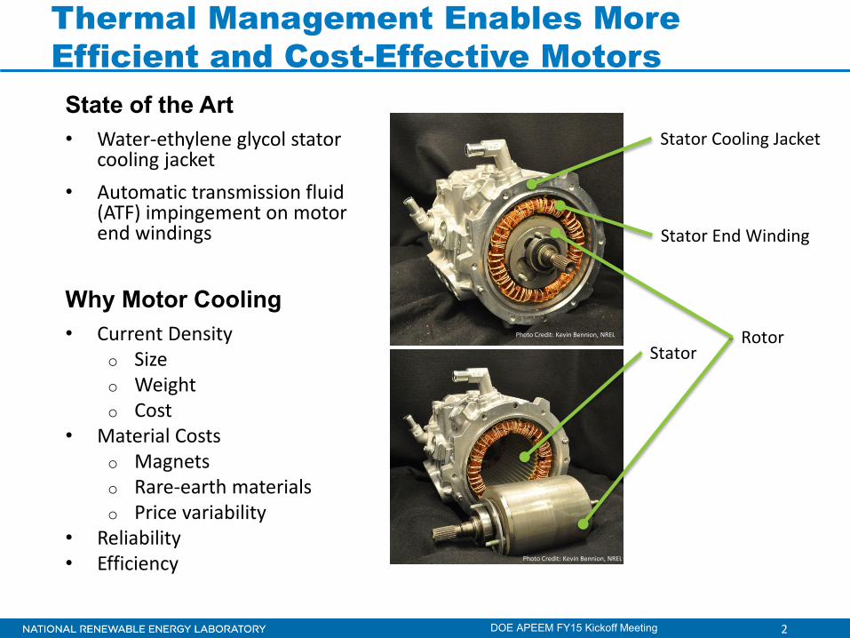
Thermal Management Enables More Efficient and Cost-Effective Motors
DOE APEEM FY15 Kickoff Meeting
State of the Art • Water-ethylene glycol stator
cooling jacket • Automatic transmission fluid
(ATF) impingement on motor end windings
Why Motor Cooling • Current Density
o Size o Weight o Cost
• Material Costs o Magnets o Rare-earth materials o Price variability
• Reliability • Efficiency
Stator Cooling Jacket
Stator End Winding
Rotor Stator
Photo Credit: Kevin Bennion, NREL
Photo Credit: Kevin Bennion, NREL
3
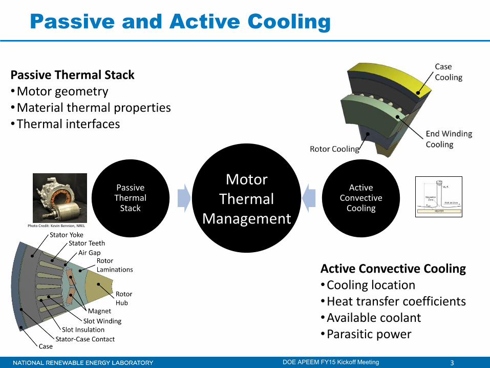
Passive and Active Cooling
DOE APEEM FY15 Kickoff Meeting
Passive Thermal
Stack
Active Convective
Cooling
Motor Thermal
Management
Passive Thermal Stack •Motor geometry •Material thermal properties •Thermal interfaces
Active Convective Cooling •Cooling location •Heat transfer coefficients •Available coolant •Parasitic power
Photo Credit: Kevin Bennion, NREL
4
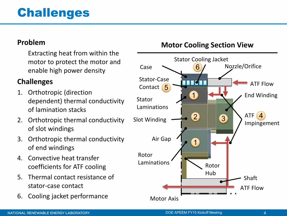
Challenges
DOE APEEM FY15 Kickoff Meeting
Stator Laminations
Slot Winding
Rotor Laminations Rotor
Hub
Case
Air Gap
Stator-Case Contact
Nozzle/Orifice
ATF Impingement
Shaft ATF Flow
ATF Flow
Stator Cooling Jacket
End Winding
Motor Axis
Motor Cooling Section View
4
1
1
2 3
5
6
Problem Extracting heat from within the motor to protect the motor and enable high power density
Challenges 1. Orthotropic (direction
dependent) thermal conductivity of lamination stacks
2. Orthotropic thermal conductivity of slot windings
3. Orthotropic thermal conductivity of end windings
4. Convective heat transfer coefficients for ATF cooling
5. Thermal contact resistance of stator-case contact
6. Cooling jacket performance

5
Proposed Research Objectives
DOE APEEM FY15 Kickoff Meeting
Problem
Core Thermal Capabilities and Research Tasks
Objective Support broad industry demand for data, analysis methods, and experimental techniques to improve and better understand motor thermal management
Stator Laminations
Slot Winding
Rotor Laminations Rotor
Hub
Case
Air Gap
Stator-Case Contact
Nozzle/Orifice
ATF Impingement
Shaft ATF Flow
ATF Flow
Stator Cooling Jacket
End Winding
Motor Axis
Motor Cooling Section View
6
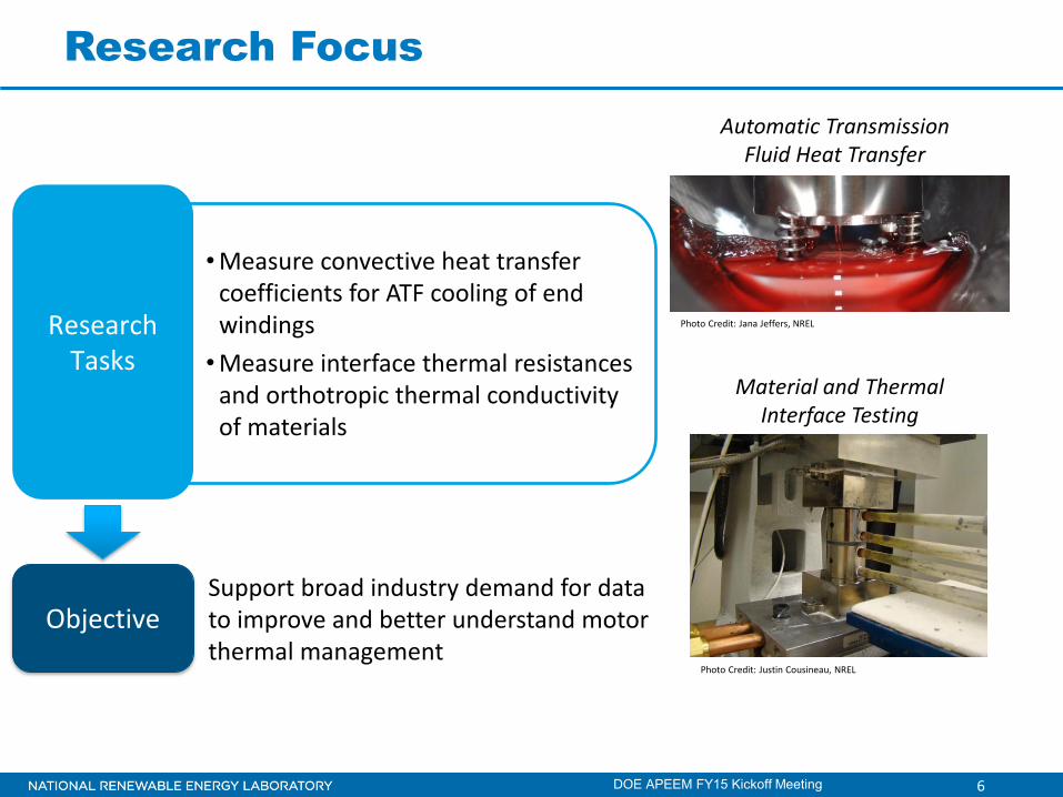
Research Focus
DOE APEEM FY15 Kickoff Meeting
•Measure convective heat transfer coefficients for ATF cooling of end windings •Measure interface thermal resistances
and orthotropic thermal conductivity of materials
Support broad industry demand for data to improve and better understand motor thermal management
Objective
Research Tasks
Automatic Transmission Fluid Heat Transfer
Material and Thermal Interface Testing
Photo Credit: Jana Jeffers, NREL
Photo Credit: Justin Cousineau, NREL
7
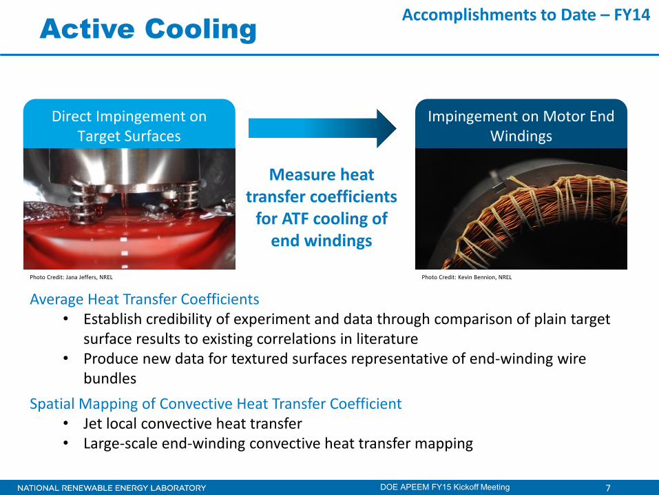
Active Cooling
DOE APEEM FY15 Kickoff Meeting
Measure heat transfer coefficients
for ATF cooling of end windings
Direct Impingement on Target Surfaces
Impingement on Motor End Windings
Average Heat Transfer Coefficients • Establish credibility of experiment and data through comparison of plain target
surface results to existing correlations in literature • Produce new data for textured surfaces representative of end-winding wire
bundles Spatial Mapping of Convective Heat Transfer Coefficient
• Jet local convective heat transfer • Large-scale end-winding convective heat transfer mapping
Photo Credit: Jana Jeffers, NREL Photo Credit: Kevin Bennion, NREL
Accomplishments to Date – FY14
8
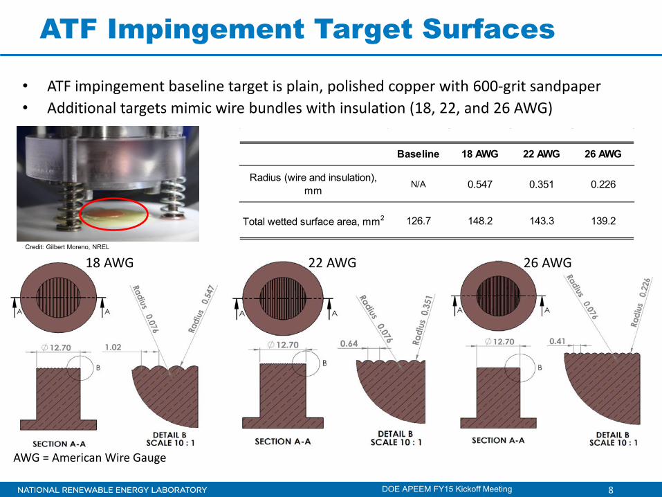
ATF Impingement Target Surfaces
DOE APEEM FY15 Kickoff Meeting
Baseline 18 AWG 22 AWG 26 AWG
Radius (wire and insulation), mm
N/A 0.547 0.351 0.226
Total wetted surface area, mm2 126.7 148.2 143.3 139.2
• ATF impingement baseline target is plain, polished copper with 600-grit sandpaper • Additional targets mimic wire bundles with insulation (18, 22, and 26 AWG)
AWG = American Wire Gauge
18 AWG 22 AWG 26 AWG Credit: Gilbert Moreno, NREL
9
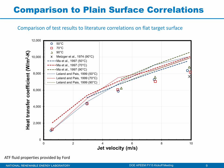
Comparison to Plain Surface Correlations
0
2,000
4,000
6,000
8,000
10,000
12,000
0 2 4 6 8 10
Hea
t tra
nsfe
r coe
ffici
ent (
W/m
2 -K
)
Jet velocity (m/s)
50°C70°C90°CMetzger et al., 1974 (90°C)Ma et al., 1997 (50°C)Ma et al., 1997 (70°C)Ma et al., 1997 (90°C)Leland and Pais, 1999 (50°C)Leland and Pais, 1999 (70°C)Leland and Pais, 1999 (90°C)
DOE APEEM FY15 Kickoff Meeting
Comparison of test results to literature correlations on flat target surface
ATF fluid properties provided by Ford
10
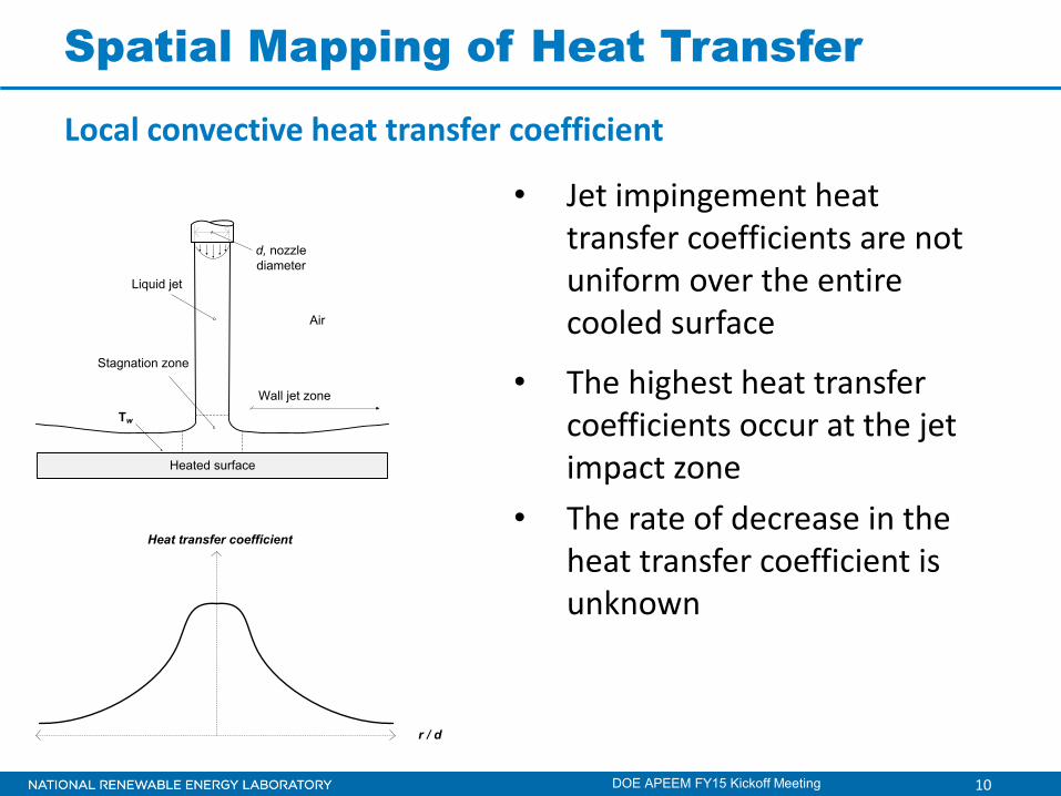
Spatial Mapping of Heat Transfer
DOE APEEM FY15 Kickoff Meeting
• Jet impingement heat transfer coefficients are not uniform over the entire cooled surface
• The highest heat transfer coefficients occur at the jet impact zone
• The rate of decrease in the heat transfer coefficient is unknown
Heated surface
Stagnation zone
Wall jet zone
d, nozzle diameter
Tw
Liquid jet
Air
r / d
Heat transfer coefficient
Local convective heat transfer coefficient
11
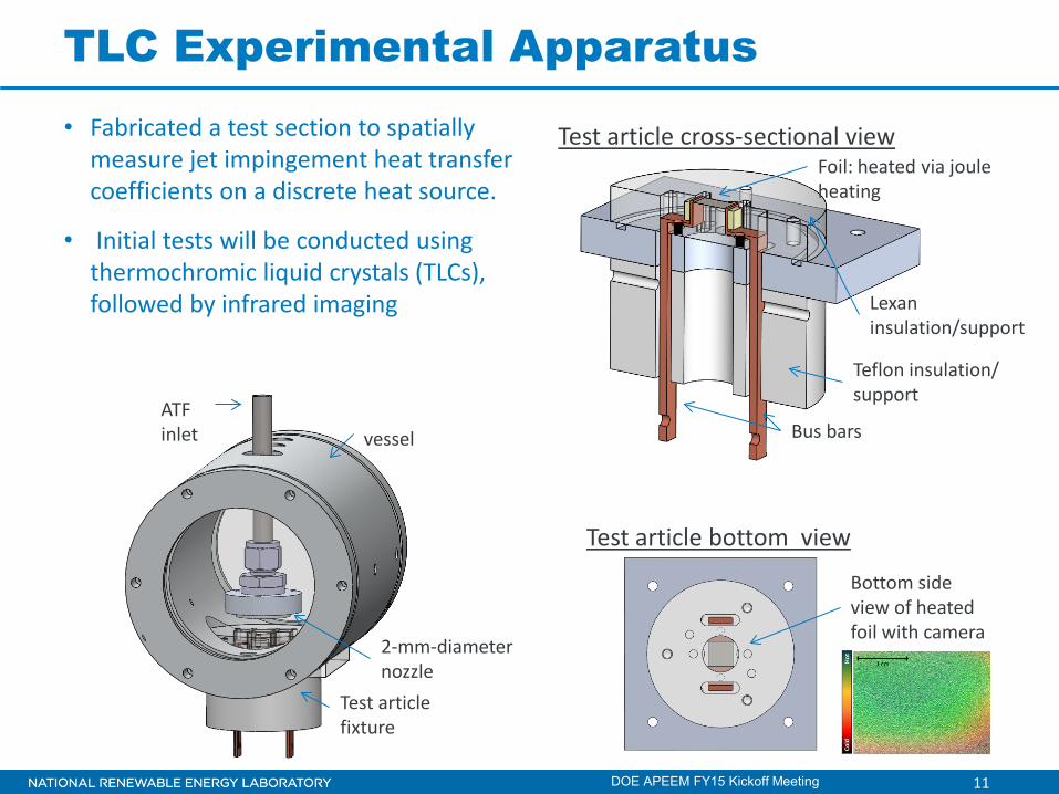
TLC Experimental Apparatus • Fabricated a test section to spatially
measure jet impingement heat transfer coefficients on a discrete heat source.
• Initial tests will be conducted using thermochromic liquid crystals (TLCs), followed by infrared imaging
DOE APEEM FY15 Kickoff Meeting
vessel ATF inlet
2-mm-diameter nozzle
Test article fixture
Foil: heated via joule heating
Lexan insulation/support
Bus bars
Test article cross-sectional view
Teflon insulation/ support
Test article bottom view
Bottom side view of heated foil with camera
12
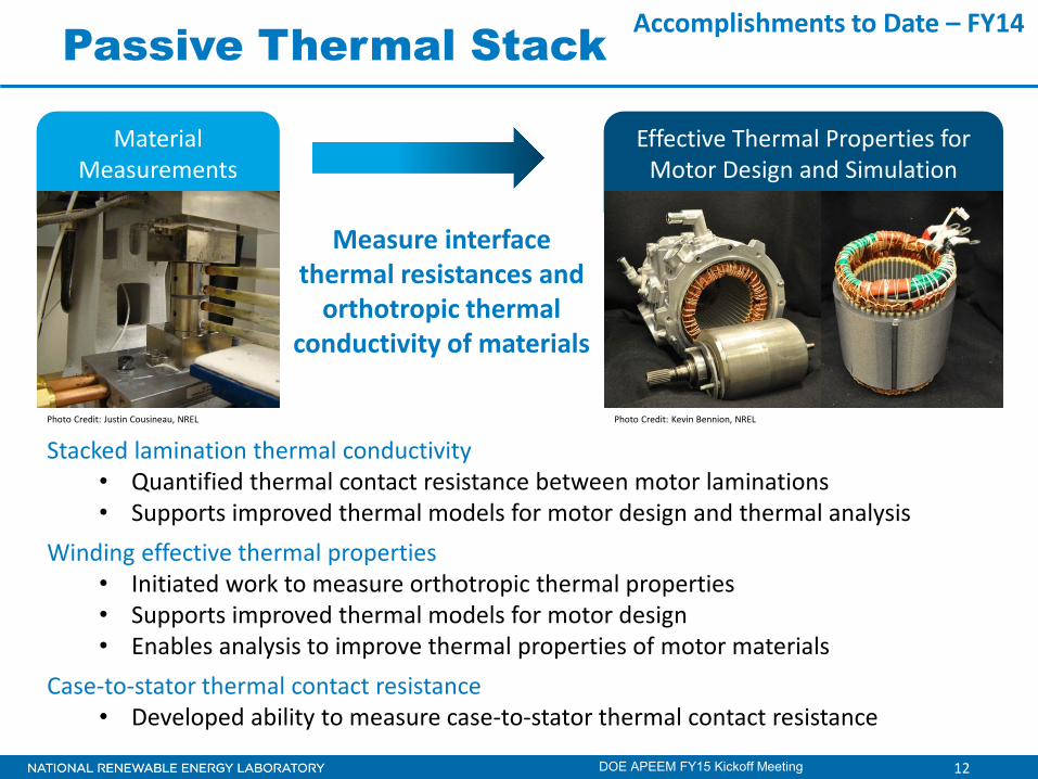
Passive Thermal Stack
Measure interface thermal resistances and
orthotropic thermal conductivity of materials
DOE APEEM FY15 Kickoff Meeting
Material Measurements
Effective Thermal Properties for Motor Design and Simulation
Stacked lamination thermal conductivity • Quantified thermal contact resistance between motor laminations • Supports improved thermal models for motor design and thermal analysis
Winding effective thermal properties • Initiated work to measure orthotropic thermal properties • Supports improved thermal models for motor design • Enables analysis to improve thermal properties of motor materials
Case-to-stator thermal contact resistance • Developed ability to measure case-to-stator thermal contact resistance
Photo Credit: Kevin Bennion, NREL Photo Credit: Justin Cousineau, NREL
Accomplishments to Date – FY14
13
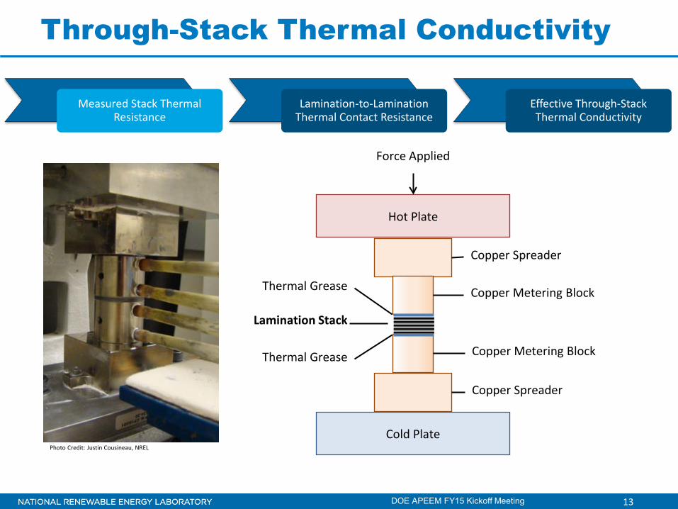
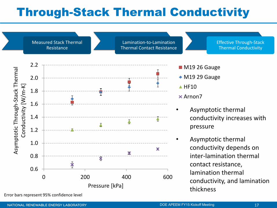
Through-Stack Thermal Conductivity
DOE APEEM FY15 Kickoff Meeting
Measured Stack Thermal Resistance
Lamination-to-Lamination Thermal Contact Resistance
Effective Through-Stack Thermal Conductivity
Cold Plate
Hot Plate
Copper Spreader
Copper Spreader
Copper Metering Block
Copper Metering Block
Lamination Stack
Thermal Grease
Thermal Grease
Force Applied
Photo Credit: Justin Cousineau, NREL

14
Through-Stack Thermal Conductivity
Measured Stack Thermal Resistance
Lamination-to-Lamination Thermal Contact Resistance
Effective Through-Stack Thermal Conductivity
0
500
1000
1500
2000
2500
0 2 4 6 8 10
Mea
sure
d La
min
atio
n St
ack
Ther
mal
Res
istan
ce (m
m²-
K/W
]
Number of Contacts
M19 29 Gauge, 138 kPa Data
Data with Systematic Error
Weighted Curve Fit
• Lamination-to-lamination thermal contact resistance calculated from slope of weighted curve fit
Cold Plate
Hot Plate
Copper Spreader
Copper Spreader
Copper Metering Block
Copper Metering Block
Lamination Stack
Thermal Grease
Thermal Grease
Force Applied
Error bars represent 95% confidence level 14
DOE APEEM FY15 Kickoff Meeting

15
Through-Stack Thermal Conductivity
• The lamination-to-lamination thermal contact resistance is affected by the surface topography and contact pressure
0
50
100
150
200
250
300
350
138 276 414 552
Lam
inat
ion-
to-L
amin
atio
n Th
erm
al C
onta
ct R
esist
ance
[m
m²-
K/W
]
Pressure [kPa]
M19 26 Gauge
M19 29 Gauge
HF10
Arnon7
Error bars represent 95% confidence level 15
Measured Stack Thermal Resistance
Lamination-to-Lamination Thermal Contact Resistance
Effective Through-Stack Thermal Conductivity
DOE APEEM FY15 Kickoff Meeting
16
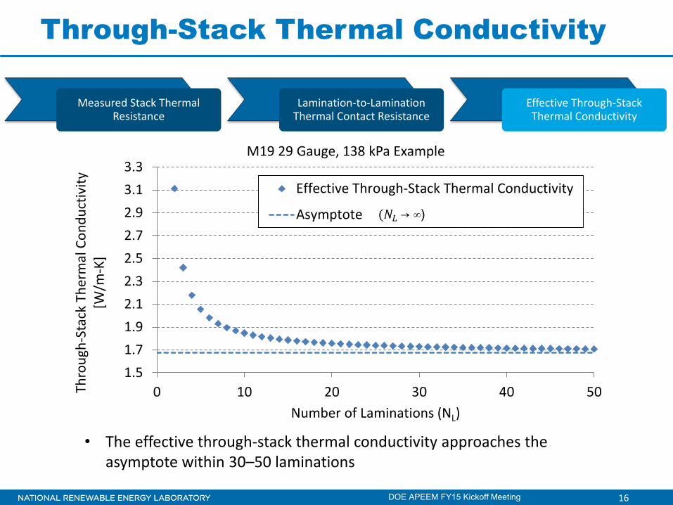
Through-Stack Thermal Conductivity
1.51.71.92.12.32.52.72.93.13.3
0 10 20 30 40 50Thro
ugh-
Stac
k Th
erm
al C
ondu
ctiv
ity
[W/m
-K]
Number of Laminations (NL)
M19 29 Gauge, 138 kPa Example
Effective Through-Stack Thermal Conductivity
Asymptote (𝑁𝑁𝐿𝐿 → ∞)
• The effective through-stack thermal conductivity approaches the asymptote within 30–50 laminations
16
Measured Stack Thermal Resistance
Lamination-to-Lamination Thermal Contact Resistance
Effective Through-Stack Thermal Conductivity
DOE APEEM FY15 Kickoff Meeting
17
Through-Stack Thermal Conductivity
DOE APEEM FY15 Kickoff Meeting 17
0.6
0.8
1.0
1.2
1.4
1.6
1.8
2.0
2.2
0 200 400 600
Asym
ptot
ic T
hrou
gh-S
tack
The
rmal
Co
nduc
tivity
[W/m
-K]
Pressure [kPa]
M19 26 Gauge
M19 29 Gauge
HF10
Arnon7
Error bars represent 95% confidence level
Measured Stack Thermal Resistance
Lamination-to-Lamination Thermal Contact Resistance
Effective Through-Stack Thermal Conductivity
• Asymptotic thermal conductivity increases with pressure
• Asymptotic thermal conductivity depends on inter-lamination thermal contact resistance, lamination thermal conductivity, and lamination thickness

18
In-Plane Lamination Thermal Conductivity
DOE APEEM FY15 Kickoff Meeting
1. Based on measured thermal conductivity of similar material 2. Calculated assuming 99% stacking factor 3. Average of measured orthotropic property in setup shown in figure
21.9 21.7 21.8
0.0
5.0
10.0
15.0
20.0
25.0
BulkMaterial
CalculatedValue
Measured
In-P
lane
The
rmal
Con
duct
ivity
[W/m
-K]
M19 29 Gauge Laminations
1 2
3
Photo Credit: Justin Cousineau, NREL
• Confirmed in-plane thermal conductivity is close to bulk material thermal conductivity

19
FY15 Tasks to Achieve Key Deliverable
DOE APEEM FY15 Kickoff Meeting
2014
Oct
Nov
Dec
2015
Jan
Feb
Mar
Apr
May
Jun
Jul
Aug
Sep
ATF impingement experiments to measure variation in local convective heat transfer coefficients
Deliverable
Publications for End-
Winding Heat Transfer
Go/ No-Go
Select passive thermal materials for bench-level testing in partnership with ORNL
End-winding spatial mapping of ATF convective heat transfer coefficients on end-winding features
Thermal measurements of passive thermal stack elements in collaboration with Oak Ridge National Laboratory (ORNL) • Winding thermal properties • Contact interfaces • Thermal analysis support in collaboration with ORNL
motor research

20
Local ATF Jet Heat Transfer Mapping
111°C
64°C
Bottom view of test article Heated foil temperature distribution
Thermal-electrical finite element analysis (FEA) reveals edge effects mostly associated with copper bus bars • ∆T across foil 47°C (most of heat loss to copper bars) • 85% of foil heater power dissipated by jet
DOE APEEM FY15 Kickoff Meeting
Spatially measure jet impingement heat transfer coefficients on a discrete heat source.
21
Local ATF Jet Heat Transfer Mapping
Bottom view of test article Heated foil temperature distribution
Use of guard heaters minimize edge effects through the use of guard heaters • ∆T across foil 7°C (heat loss to copper decreased) • 98% of foil heater power dissipated by jet
Guard heaters 112°C
105°C
DOE APEEM FY15 Kickoff Meeting
Spatially measure jet impingement heat transfer coefficients on a discrete heat source.

22
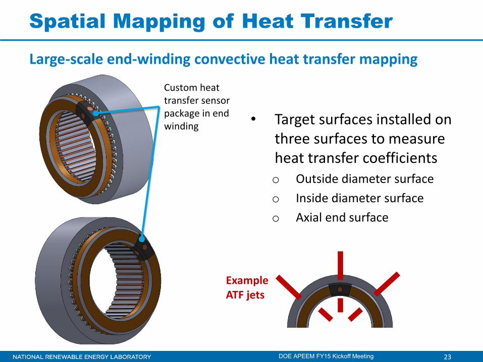
Spatial Mapping of Heat Transfer
• Map the large-scale spatial distribution of the heat transfer coefficients over motor end windings
• Study effects of
o Oil jet placement
o ATF free flow over end-winding surfaces
o Jet interactions
Large-scale end-winding convective heat transfer mapping
Photo Credit: Kevin Bennion, NREL
DOE APEEM FY15 Kickoff Meeting
23
Spatial Mapping of Heat Transfer
• Target surfaces installed on three surfaces to measure heat transfer coefficients o Outside diameter surface o Inside diameter surface o Axial end surface
Custom heat transfer sensor package in end winding
Large-scale end-winding convective heat transfer mapping
Example ATF jets
DOE APEEM FY15 Kickoff Meeting
24
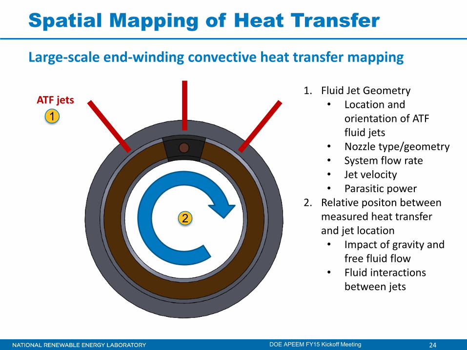
Spatial Mapping of Heat Transfer
DOE APEEM FY15 Kickoff Meeting
ATF jets
2
1
Large-scale end-winding convective heat transfer mapping
1. Fluid Jet Geometry • Location and
orientation of ATF fluid jets
• Nozzle type/geometry • System flow rate • Jet velocity • Parasitic power
2. Relative positon between measured heat transfer and jet location • Impact of gravity and
free fluid flow • Fluid interactions
between jets
25
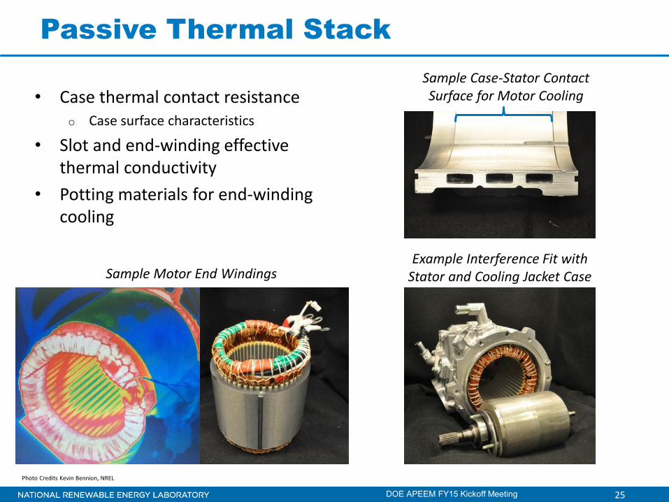
Passive Thermal Stack
DOE APEEM FY15 Kickoff Meeting
• Case thermal contact resistance o Case surface characteristics
• Slot and end-winding effective thermal conductivity
• Potting materials for end-winding cooling
Sample Case-Stator Contact Surface for Motor Cooling
Example Interference Fit with Stator and Cooling Jacket Case Sample Motor End Windings
Photo Credits Kevin Bennion, NREL
26
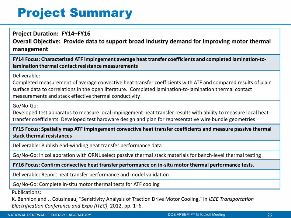
Publications: K. Bennion and J. Cousineau, “Sensitivity Analysis of Traction Drive Motor Cooling,” in IEEE Transportation Electrification Conference and Expo (ITEC), 2012, pp. 1–6.
Project Summary
DOE APEEM FY15 Kickoff Meeting
Project Duration: FY14–FY16 Overall Objective: Provide data to support broad Industry demand for improving motor thermal management FY14 Focus: Characterized ATF impingement average heat transfer coefficients and completed lamination-to-lamination thermal contact resistance measurements
Deliverable: Completed measurement of average convective heat transfer coefficients with ATF and compared results of plain surface data to correlations in the open literature. Completed lamination-to-lamination thermal contact measurements and stack effective thermal conductivity
Go/No-Go: Developed test apparatus to measure local impingement heat transfer results with ability to measure local heat transfer coefficients. Developed test hardware design and plan for representative wire bundle geometries
FY15 Focus: Spatially map ATF impingement convective heat transfer coefficients and measure passive thermal stack thermal resistances
Deliverable: Publish end-winding heat transfer performance data
Go/No-Go: In collaboration with ORNL select passive thermal stack materials for bench-level thermal testing
FY16 Focus: Confirm convective heat transfer performance on in-situ motor thermal performance tests.
Deliverable: Report heat transfer performance and model validation
Go/No-Go: Complete in-situ motor thermal tests for ATF cooling
27
Technology-to-Market Plan
DOE APEEM FY15 Kickoff Meeting
• This research impacts industry needs because … o The heat flow, temperature distribution, and fluid dynamics for motor
thermal management are complex problems o Data on cooling convective heat transfer coefficients and heat spreading
within the motor are needed to improve motor performance within cost, efficiency, and reliability constraints
• This research is on the path to commercialization because … o The research is reviewed by and shared with industry experts o The data are used by industry experts in the analysis and design of electric
motors
28
Partners/Collaborators
DOE APEEM FY15 Kickoff Meeting
• Industry o Motor industry suppliers, end users, and researchers
– Input on research and test plans – Sharing of experimental data, modeling results, and analysis methods – Companies providing research input, requesting data, or supplying data
include: Ford, Chrysler, GM, Tesla, UQM Technologies, Remy, Magna, John Deere, Oshkosh
• Other Government Laboratories o ORNL
– Support from benchmarking activities – Collaboration on motor designs to reduce or eliminate rare-earth
materials – Collaboration on materials with improved thermal properties
Potting materials for end windings for improved heat transfer Slot winding materials

NREL is a national laboratory of the U.S. Department of Energy, Office of Energy Efficiency and Renewable Energy, operated by the Alliance for Sustainable Energy, LLC.
For more information, contact:
Principal Investigator Kevin Bennion [email protected] Phone: (303)275-4447 APEEM Task Leader: Sreekant Narumanchi [email protected] Phone: (303)275-4062
Acknowledgments:
Susan Rogers and Steven Boyd U.S. Department of Energy
Team Members:
Justin Cousineau Charlie King Gilbert Moreno Caitlin Stack Tim Burress (ORNL) Andy Wereszczak (ORNL)