electric relays: principles and applications
TRANSCRIPT

Electric RelaysPrinciples and Applications
DK884X_half-series-title 10/19/05 10:45 AM Page A
© 2006 by Taylor & Francis Group, LLC
ELECTRICAL AND COMPUTER ENGINEERINGA Series of Reference Books and Textbooks
FOUNDING EDITOR
Marlin O. ThurstonDepartment of Electrical Engineering
The Ohio State UniversityColumbus, Ohio
1. Rational Fault Analysis, edited by Richard Saeks and S. R. Liberty
2. Nonparametric Methods in Communications, edited by P. Papantoni-Kazakos and Dimitri Kazakos
3. Interactive Pattern Recognition, Yi-tzuu Chien4. Solid-State Electronics, Lawrence E. Murr5. Electronic, Magnetic, and Thermal Properties of Solid
Materials, Klaus Schröder6. Magnetic-Bubble Memory Technology, Hsu Chang7. Transformer and Inductor Design Handbook,
Colonel Wm. T. McLyman8. Electromagnetics: Classical and Modern Theory
and Applications, Samuel Seely and Alexander D. Poularikas9. One-Dimensional Digital Signal Processing, Chi-Tsong Chen10. Interconnected Dynamical Systems, Raymond A. DeCarlo
and Richard Saeks11. Modern Digital Control Systems, Raymond G. Jacquot12. Hybrid Circuit Design and Manufacture, Roydn D. Jones13. Magnetic Core Selection for Transformers and Inductors:
A User’s Guide to Practice and Specification, Colonel Wm. T. McLyman
14. Static and Rotating Electromagnetic Devices, Richard H. Engelmann
15. Energy-Efficient Electric Motors: Selection and Application, John C. Andreas
16. Electromagnetic Compossibility, Heinz M. Schlicke17. Electronics: Models, Analysis, and Systems,
James G. Gottling18. Digital Filter Design Handbook, Fred J. Taylor19. Multivariable Control: An Introduction, P. K. Sinha20. Flexible Circuits: Design and Applications, Steve Gurley,
with contributions by Carl A. Edstrom, Jr., Ray D. Greenway, and William P. Kelly
DK884X_half-series-title 10/19/05 10:45 AM Page B
© 2006 by Taylor & Francis Group, LLC
21. Circuit Interruption: Theory and Techniques, Thomas E. Browne, Jr.
22. Switch Mode Power Conversion: Basic Theory and Design, K. Kit Sum
23. Pattern Recognition: Applications to Large Data-SetProblems, Sing-Tze Bow
24. Custom-Specific Integrated Circuits: Design and Fabrication,Stanley L. Hurst
25. Digital Circuits: Logic and Design, Ronald C. Emery26. Large-Scale Control Systems: Theories and Techniques,
Magdi S. Mahmoud, Mohamed F. Hassan, and Mohamed G. Darwish
27. Microprocessor Software Project Management, Eli T. Fathi and Cedric V. W. Armstrong (Sponsored by Ontario Centre for Microelectronics)
28. Low Frequency Electromagnetic Design, Michael P. Perry29. Multidimensional Systems: Techniques and Applications,
edited by Spyros G. Tzafestas30. AC Motors for High-Performance Applications: Analysis
and Control, Sakae Yamamura31. Ceramic Motors for Electronics: Processing, Properties,
and Applications, edited by Relva C. Buchanan32. Microcomputer Bus Structures and Bus Interface Design,
Arthur L. Dexter33. End User’s Guide to Innovative Flexible Circuit Packaging,
Jay J. Miniet34. Reliability Engineering for Electronic Design,
Norman B. Fuqua35. Design Fundamentals for Low-Voltage Distribution
and Control, Frank W. Kussy and Jack L. Warren36. Encapsulation of Electronic Devices and Components,
Edward R. Salmon37. Protective Relaying: Principles and Applications,
J. Lewis Blackburn38. Testing Active and Passive Electronic Components,
Richard F. Powell39. Adaptive Control Systems: Techniques and Applications,
V. V. Chalam40. Computer-Aided Analysis of Power Electronic Systems,
Venkatachari Rajagopalan41. Integrated Circuit Quality and Reliability, Eugene R. Hnatek42. Systolic Signal Processing Systems, edited by
Earl E. Swartzlander, Jr.43. Adaptive Digital Filters and Signal Analysis,
Maurice G. Bellanger44. Electronic Ceramics: Properties, Configuration,
and Applications, edited by Lionel M. Levinson
DK884X_half-series-title 10/19/05 10:45 AM Page C
© 2006 by Taylor & Francis Group, LLC
45. Computer Systems Engineering Management, Robert S. Alford
46. Systems Modeling and Computer Simulation, edited by Naim A. Kheir
47. Rigid-Flex Printed Wiring Design for Production Readiness, Walter S. Rigling
48. Analog Methods for Computer-Aided Circuit Analysis and Diagnosis, edited by Takao Ozawa
49. Transformer and Inductor Design Handbook: Second Edition,Revised and Expanded, Colonel Wm. T. McLyman
50. Power System Grounding and Transients: An Introduction, A. P. Sakis Meliopoulos
51. Signal Processing Handbook, edited by C. H. Chen52. Electronic Product Design for Automated Manufacturing,
H. Richard Stillwell53. Dynamic Models and Discrete Event Simulation,
William Delaney and Erminia Vaccari54. FET Technology and Application: An Introduction,
Edwin S. Oxner55. Digital Speech Processing, Synthesis, and Recognition,
Sadaoki Furui56. VLSI RISC Architecture and Organization, Stephen B. Furber57. Surface Mount and Related Technologies, Gerald Ginsberg58. Uninterruptible Power Supplies: Power Conditioners
for Critical Equipment, David C. Griffith59. Polyphase Induction Motors: Analysis, Design,
and Application, Paul L. Cochran60. Battery Technology Handbook, edited by H. A. Kiehne61. Network Modeling, Simulation, and Analysis, edited by
Ricardo F. Garzia and Mario R. Garzia62. Linear Circuits, Systems, and Signal Processing:
Advanced Theory and Applications, edited by Nobuo Nagai63. High-Voltage Engineering: Theory and Practice, edited by
M. Khalifa64. Large-Scale Systems Control and Decision Making,
edited by Hiroyuki Tamura and Tsuneo Yoshikawa65. Industrial Power Distribution and Illuminating Systems,
Kao Chen66. Distributed Computer Control for Industrial Automation,
Dobrivoje Popovic and Vijay P. Bhatkar67. Computer-Aided Analysis of Active Circuits, Adrian Ioinovici68. Designing with Analog Switches, Steve Moore69. Contamination Effects on Electronic Products,
Carl J. Tautscher70. Computer-Operated Systems Control, Magdi S. Mahmoud71. Integrated Microwave Circuits, edited by Yoshihiro Konishi
DK884X_half-series-title 10/19/05 10:45 AM Page D
© 2006 by Taylor & Francis Group, LLC
72. Ceramic Materials for Electronics: Processing, Properties, and Applications, Second Edition, Revised and Expanded, edited by Relva C. Buchanan
73. Electromagnetic Compatibility: Principles and Applications, David A. Weston
74. Intelligent Robotic Systems, edited by Spyros G. Tzafestas75. Switching Phenomena in High-Voltage Circuit Breakers,
edited by Kunio Nakanishi76. Advances in Speech Signal Processing, edited by
Sadaoki Furui and M. Mohan Sondhi77. Pattern Recognition and Image Preprocessing, Sing-Tze Bow78. Energy-Efficient Electric Motors: Selection and Application,
Second Edition, John C. Andreas79. Stochastic Large-Scale Engineering Systems, edited by
Spyros G. Tzafestas and Keigo Watanabe80. Two-Dimensional Digital Filters, Wu-Sheng Lu
and Andreas Antoniou 81. Computer-Aided Analysis and Design of Switch-Mode
Power Supplies, Yim-Shu Lee82. Placement and Routing of Electronic Modules,
edited by Michael Pecht83. Applied Control: Current Trends and Modern Methodologies,
edited by Spyros G. Tzafestas84. Algorithms for Computer-Aided Design of Multivariable
Control Systems, Stanoje Bingulac and Hugh F. VanLandingham
85. Symmetrical Components for Power Systems Engineering, J. Lewis Blackburn
86. Advanced Digital Signal Processing: Theory and Applications, Glenn Zelniker and Fred J. Taylor
87. Neural Networks and Simulation Methods, Jian-Kang Wu88. Power Distribution Engineering: Fundamentals
and Applications, James J. Burke89. Modern Digital Control Systems: Second Edition,
Raymond G. Jacquot90. Adaptive IIR Filtering in Signal Processing and Control,
Phillip A. Regalia91. Integrated Circuit Quality and Reliability: Second Edition,
Revised and Expanded, Eugene R. Hnatek92. Handbook of Electric Motors, edited by
Richard H. Engelmann and William H. Middendorf93. Power-Switching Converters, Simon S. Ang94. Systems Modeling and Computer Simulation:
Second Edition, Naim A. Kheir95. EMI Filter Design, Richard Lee Ozenbaugh96. Power Hybrid Circuit Design and Manufacture,
Haim Taraseiskey
DK884X_half-series-title 10/19/05 10:45 AM Page E
© 2006 by Taylor & Francis Group, LLC
97. Robust Control System Design: Advanced State SpaceTechniques, Chia-Chi Tsui
98. Spatial Electric Load Forecasting, H. Lee Willis99. Permanent Magnet Motor Technology: Design
and Applications, Jacek F. Gieras and Mitchell Wing100. High Voltage Circuit Breakers: Design and Applications,
Ruben D. Garzon101. Integrating Electrical Heating Elements in Appliance Design,
Thor Hegbom102. Magnetic Core Selection for Transformers and Inductors:
A User’s Guide to Practice and Specification, Second Edition,Colonel Wm. T. McLyman
103. Statistical Methods in Control and Signal Processing, edited by Tohru Katayama and Sueo Sugimoto
104. Radio Receiver Design, Robert C. Dixon105. Electrical Contacts: Principles and Applications,
edited by Paul G. Slade106. Handbook of Electrical Engineering Calculations,
edited by Arun G. Phadke107. Reliability Control for Electronic Systems,
Donald J. LaCombe108. Embedded Systems Design with 8051 Microcontrollers:
Hardware and Software, Zdravko Karakehayov, Knud Smed Christensen, and Ole Winther
109. Pilot Protective Relaying, edited by Walter A. Elmore110. High-Voltage Engineering: Theory and Practice, Second
Edition, Revised and Expanded, Mazen Abdel-Salam,Hussein Anis, Ahdab El-Morshedy, and Roshdy Radwan
111. EMI Filter Design: Second Edition, Revised and Expanded, Richard Lee Ozenbaugh
112. Electromagnetic Compatibility: Principles and Applications,Second Edition, Revised and Expanded, David Weston
113. Permanent Magnet Motor Technology: Design andApplications, Second Edition, Revised and Expanded, Jacek F. Gieras and Mitchell Wing
114. High Voltage Circuit Breakers: Design and Applications, Second Edition, Revised and Expanded, Ruben D. Garzon
115. High Reliability Magnetic Devices: Design and Fabrication,Colonel Wm. T. McLyman
116. Practical Reliability of Electronic Equipment and Products,Eugene R. Hnatek
117. Electromagnetic Modeling by Finite Element Methods,João Pedro A. Bastos and Nelson Sadowski
118. Battery Technology Handbook, Second Edition, edited by H. A. Kiehne
119. Power Converter Circuits, William Shepherd and Li Zhang
DK884X_half-series-title 10/19/05 10:45 AM Page F
© 2006 by Taylor & Francis Group, LLC
120. Handbook of Electric Motors: Second Edition, Revised and Expanded, edited by Hamid A. Toliyat and Gerald B. Kliman
121. Transformer and Inductor Design Handbook, Colonel Wm T. McLyman
122. Energy Efficient Electric Motors: Selection and Application, Third Edition, Revised and Expanded, Ali Emadi
123. Power-Switching Converters, Second Edition, Simon Ang and Alejandro Oliva
124. Process Imaging For Automatic Control, edited by David M. Scott and Hugh McCann
125. Handbook of Automotive Power Electronics and MotorDrives, Ali Emadi
126. Adaptive Antennas and Receivers, edited by Melvin M. Weiner
127. SPICE for Power Electronics and Electric Power, Second Edition, Muhammad H. Rashid and Hasan M. Rashid
128. Gaseous Electronics: Theory and Practice, Gorur G. Raju129. Noise of Polyphase Electric Motors, Jacek F. Gieras,
Chong Wang and Joseph Cho Lai130. Electric Relays: Principles and Applications,
Vladimir Gurevich
DK884X_half-series-title 10/19/05 10:45 AM Page G
© 2006 by Taylor & Francis Group, LLC

Electric RelaysPrinciples and Applications
Vladimir GurevichIsrael Electric Corporation
Haifa, Israel
A CRC title, part of the Taylor & Francis imprint, a member of theTaylor & Francis Group, the academic division of T&F Informa plc.
Boca Raton London New York
DK884X_half-series-title 10/19/05 10:45 AM Page i
© 2006 by Taylor & Francis Group, LLC

Published in 2006 byCRC PressTaylor & Francis Group 6000 Broken Sound Parkway NW, Suite 300Boca Raton, FL 33487-2742
© 2006 by Taylor & Francis Group, LLCCRC Press is an imprint of Taylor & Francis Group
No claim to original U.S. Government worksPrinted in the United States of America on acid-free paper10 9 8 7 6 5 4 3 2 1
International Standard Book Number-10: 0-8493-4188-4 (Hardcover) International Standard Book Number-13: 978-0-8493-4188-5 (Hardcover) Library of Congress Card Number 2005049392
This book contains information obtained from authentic and highly regarded sources. Reprinted material is quoted withpermission, and sources are indicated. A wide variety of references are listed. Reasonable efforts have been made to publishreliable data and information, but the author and the publisher cannot assume responsibility for the validity of all materialsor for the consequences of their use.
No part of this book may be reprinted, reproduced, transmitted, or utilized in any form by any electronic, mechanical, orother means, now known or hereafter invented, including photocopying, microfilming, and recording, or in any informationstorage or retrieval system, without written permission from the publishers.
01923, 978-750-8400. CCC is a not-for-profit organization that provides licenses and registration for a variety of users. For
Trademark Notice: Product or corporate names may be trademarks or registered trademarks, and are used only foridentification and explanation without intent to infringe.
Library of Congress Cataloging-in-Publication Data
Gurevich, Vladimir, 1956-Electric relays : principles and applications / Vladimir Gurevich.
p. cm.Includes bibliographical references and index.ISBN 0-8493-4188-4 (alk. paper)1. Electric relays. I. Title.
TK7872.R38.G87 2005621.31’7--dc22 2005049392
Visit the Taylor & Francis Web site at http://www.taylorandfrancis.com
and the CRC Press Web site at http://www.crcpress.com
Taylor & Francis Group is the Academic Division of Informa plc.
DK884X_Discl.fm Page 1 Wednesday, November 2, 2005 3:01 PM
© 2006 by Taylor & Francis Group, LLC
For permission to photocopy or use material electronically from this work, please access www.copyright.com
organizations that have been granted a photocopy license by the CCC, a separate system of payment has been arranged.
(http://www.copyright.com/) or contact the Copyright Clearance Center, Inc. (CCC) 222 Rosewood Drive, Danvers, MA

In memory of my beloved father Igor Gurevich who tragicallyperished in January 2003
GUREVICH / Electric Relays: Principles and Practises DK884X_prelims Final Proof page xi 9.11.2005 7:56pm
© 2006 by Taylor & Francis Group, LLC

If we do not find anything very pleasant,at least we shall find something new
Voltaire
GUREVICH / Electric Relays: Principles and Practises DK884X_prelims Final Proof page xiii 9.11.2005 7:56pm
© 2006 by Taylor & Francis Group, LLC
Introduction
This book contains a description of electrical relays, their principles of operation, andapplications for all basic types, for as widespread as knowledge of the subject is, it is stillnot abundant.
The scope of this book is very broad and unique in the sense that this book representsthe first illustrated encyclopedia of electrical relays.
The historical background of the design of many different types of relays, not alwaysknown even to specialists, has been included and given much attention not only becauseit is interesting, but more importantly because of the frequent need for a display ofexpertise on the subject, enhancing the perception of competency of the specialist.
In describing some of the complicated types of relays (for example, electronic relays),the related issues of design and principles of operation of the relay components arediscussed too (in our case vacuum, gas discharge, and semiconductor devices), whichallows the reader to better understand the principles of operation of the described relays,without having to refer to additional information sources.
The book is written in a clear and easy-to-understand language, without mathematicaltreatment, and includes numerous illustrations, making it attractive not only for special-ists in relays, but also for a wide range of engineers, technicians, and students interestedin extending their knowledge in electric relays. Lecturers and university teachers will alsofind a lot of valuable material for their lectures in the book.
GUREVICH / Electric Relays: Principles and Practises DK884X_prelims Final Proof page xv 9.11.2005 7:56pm
© 2006 by Taylor & Francis Group, LLC
Acknowledgments
I wish to thank Mary Malinkovich for her enormous assistance in translating this manu-script to English and Haim Ron for reading and editing the final manuscript.
Acknowledgment is also made to the following firms and organizations for their kindpermission to allow me to use various information and illustrations:
ABB OyABB Switzerland Ltd — SemiconductorsAirpax Corp.AutomationDirectBehlke Electronic GmbHCIGRE Central OfficeComus Group CompaniesDowetron GmbHEaton Corp.EHG Elektroholding GmbH (AEG)General Electric Co.GigavacGruner AGHermetic Switch, Inc.Instrumentation & Control System, Inc.Jennigs TechnologyLeach InternationalLEM ComponentsMagnecraft & Struthers-DunnMaxim Integrated Products, Inc.MoellerNxtPhase Corp.Olympic Controls Corp.OPTEK TechnologyPhoenix Contact GmbH & Co. KGPowerex, Inc.Precision Timer Co., Inc.Rockwell AutomationRoss Engineering Corp.Siemens AGSmithsonian Institution Archives (Joseph Henry Papers)Teledyne TechnologiesTexas InstrumentsToshiba Corp.Tyco ElectronicsYaskawa Electric America
Finally and most important, my utmost thanks and appreciation to my wife Tatiana,who has endured the writing of this (my third!) book, for her never-ending patience.
GUREVICH / Electric Relays: Principles and Practises DK884X_prelims Final Proof page xvii 9.11.2005 7:56pm
© 2006 by Taylor & Francis Group, LLC
Preface
The electric relay is one of the most frequently used devices in modern technologicalsystems. It can be found in cars, washing machines, microwave ovens, and medicalequipment, as well as in tanks, aircraft, and ships. Practically no industry would functionwithout relays. In some complex automatic control systems in industry, the number ofrelays is estimated in hundreds and even thousands. In the power-generation industry,no power device is allowed to operate without special protection relays. Certain electricalequipment, such as power transformers, may be protected by several different kinds ofrelays, each controlling different functions.
Because relays are so widely used and there are so many types, the broad population ofengineers is unfamiliar with most of them. Generally speaking, engineers in a specifictechnical field are usually only familiar with relays that are applicable for specific devices.The same is true of specialists involved in the design and production of relays. Therefore,obtaining information on relays is a problem both for students whose future professioninvolves relay application, and for teachers in technical colleges or extension courses, whoneed up-to-date information about relays for their students.
Where can we find extensive publications that equally meet the needs of engineers,teachers, and students?
Various publications and books about relays currently on the market can be dividedinto two groups. One is generally called ‘‘Low Power Relays’’ or ‘‘Power Relays’’ (bothterms mean the same, that is, a low-power electromagnetic relay with a switching currentnot exceeding 30 A). The second group is ‘‘Protective Relaying’’ (protective relays forprotection of power networks), where the emphasis is placed not on a description of theprinciples and construction of relays, but on schematic principles of protection of elec-trical networks and calculation of their operating modes.
On the one hand, dividing the entire ‘‘world of electric relays’’ into two groupsexcludes some important relay implementations, for example relays with a switchingcurrent of hundreds of amperes, high-voltage relays, mercury relays, reed switch relays,solid-state relays, electric thermal relays, time-delay relays, safety relays, and manyothers. On the other hand, such an artificial division within the same field frequentlyresults in separate treatment of common questions regarding relays which may be ofdifferent kinds, but are actually related and should be dealt with together. Experienceaccumulated for one type of relay is not always taken into account regarding other typesof relays, even if the analogy is obvious. Moreover, modern protection relays usuallycontain electromagnetic, reed switch, or solid-state relays as output elements and expertsin relay protection must be aware of their idiosyncrasies. In addition, in many particularlypowerful and high-voltage modern electronic systems (power supplies, powerful lasers,radars, etc.) experts face challenges of providing protection against emergency states(overload, overcurrent, etc.), similar to challenges encountered by specialists in relayprotection.
Another disadvantage of current publications is that they rarely meet the full range ofengineering requirements. Some are intended mainly for experts and are abundant inequations and calculations for relays; others emphasize standards, methods of qualitycontrol, and other issues concerning production of relays; and still others are for engineersand technicians who are not experts in relays but only use relays in their equipment. Most
GUREVICH / Electric Relays: Principles and Practises DK884X_prelims Final Proof page xix 9.11.2005 7:56pm
© 2006 by Taylor & Francis Group, LLC
of these publications provide the information in such a simplified and limited way thatthey are of little practical benefit, as they do not give simple and understandable answersto many questions concerning the implementation of relays, such as the following:
. Is it possible to switch on an electric light bulb having a nominal current of 0.3Awith the assistance of a reed switch relay with a nominal switching current of1 A? (The correct answer is NO!)
. Why does a relay, which has worked well for a year, begin to drone and tomalfunction? (The reason is that the relay has been incorrectly installed withrespect to the vertical line.)
. Why does the ground fault relay (‘‘residual current device’’) malfunction? Doesit mean that the relay is out of order? (Not necessarily. Most often the reason ischanges in insulation resistance of the equipment under exposure to moisture orhigh temperature.)
To answer these questions, it is essential to have a clear understanding of how relaysfunction. That brings us to the question of what is necessary for effective study of the basicprinciples of relays of certain types. Is it enough just to analyze the specific construction ofa certain relay? The author is convinced that it is not. The reason is that when a relay of asimilar type but with a different construction is next encountered, the learning processmust begin all over again.
For each type of relay, this book includes descriptions of several types of relay con-structions, each functioning on a different basis. Moreover, readers will find full coveragehere of the historical development of relay construction — from the earliest to moderntimes. The author is convinced that only such an approach can ensure understanding ofprinciples applicable of all types of relays.
The author aimed to write a comprehensive book about relays without the disadvan-tages of other books and publications listed above. This book covers the diversity of the‘‘world of electric relays’’ and reveals the dynamics of their development — from theearliest ideas to modern constructions and applications. In order to make the bookunderstandable, not only for experts but also for laymen, the author utilizes the ‘‘pic-ture-instead-of-formula’’ principle. Such an approach enables engineers, technicians,teachers, and students who are interested in relay construction to use the book as anencyclopedia of electric relays.
Furthermore, general readers who are interested in the history of engineering willdiscover many interesting historical facts about the invention of relays. Inquisitive readerswill be able to enrich their knowledge in the field of electronics by reading the chaptersdevoted to electronic relays.
It is for the readers to decide whether the author has succeeded in attaining hisobjective.
This book consists of 16 chapters. The first four chapters cover the basic principles ofrelay construction and its major functional parts, such as contact systems, magneticsystems, etc. The following 12 chapters are devoted to various specific types of relays.Each of these chapters includes a description of the principles of relay functioning andconstruction as well as features of several different relays belonging to a certain type, butoperating on different principles and developed at different times.
The information in the book is arranged such that the reader can work with anyspecific part without having to refer to another part of the book. It is also structured tofunction as an encyclopedia of relays by facilitating consultation when the need arises. Ithelps the reader find answers to particular questions, and avoids the pitfall of forcing
GUREVICH / Electric Relays: Principles and Practises DK884X_prelims Final Proof page xx 9.11.2005 7:56pm
xx Preface
© 2006 by Taylor & Francis Group, LLC

the reader to read the whole book even though certain parts may be of only marginalinterest.
The author will be grateful for any suggestions and remarks aimed towards improve-ment of the book. Please send all comments to the publisher.
Vladimir Gurevich, Ph.D.
GUREVICH / Electric Relays: Principles and Practises DK884X_prelims Final Proof page xxi 9.11.2005 7:56pm
Preface xxi
© 2006 by Taylor & Francis Group, LLC
Contents
Introduction ................................................................................................................................. xvAcknowledgments ....................................................................................................................xviiPreface .......................................................................................................................................... xix
1 History........................................................................................................................................11.1 Relays and Horses .........................................................................................................11.2 From Oersted to Henry.................................................................................................21.3 Art Professor Samuel Morse ........................................................................................81.4 Edison’s Relay ..............................................................................................................131.5 The First Industrial Relays in Russia........................................................................14
2 Magnetic Systems of Relays................................................................................................212.1 Basic Components of and Electromagnetic Relay..................................................212.2 Hysteresis and Coercitive Force................................................................................222.3 Types of Magnetic Systems........................................................................................24
2.3.1 The Clapper-Type (Attracted-Armature) Magnetic System.................... 242.3.2 Systems with a Balanced Armature............................................................. 262.3.3 Direct Motion (Solenoid-Type) Systems and Their Peculiarities............ 30
2.4 Differences between AC and DC Relays .................................................................342.5 Some Auxiliary Elements Improving the Relay Operation..................................372.6 What Happens When a Relay Is Energized............................................................392.7 Windings of Relays: Types and Design Features...................................................42
3 Contact Systems .....................................................................................................................493.1 Designs of Basic Types of Contacts ..........................................................................493.2 Silver, Gold, Platinum.................................................................................................523.3 Contacts with Two-Stage Commutation..................................................................543.4 What is the Purpose of ‘‘Contact Pressure?’’ ..........................................................553.5 Self-Cleaning Contacts ................................................................................................563.6 Self-Adjusting Contacts ..............................................................................................583.7 When Power Does Not Equal Multiplication by Current and Voltage..............583.8 Split, Make-Before-Break, High-Frequency Contacts ............................................653.9 Compensation for Shock and Electro-dynamic Forces in Contacts ....................683.10 Sparking Contacts and Their Control.......................................................................723.11 High-Power Contact Systems ....................................................................................783.12 Mercury Displacement Relays...................................................................................85
4 External Design of Relays....................................................................................................914.1 Environmental Impact on Relays..............................................................................914.2 Wood and Cardboard: First Protection Shield for Relays ....................................924.3 Is a Sealed Relay Always Better Than an Open One?...........................................964.4 Outlets, Terminal Sockets and ‘‘Containers’’ for Relays.......................................994.5 Indicators of Operation and Test Buttons .............................................................1104.6 Relays That Do Not Look Like Relays at All ........................................................110
GUREVICH / Electric Relays: Principles and Practises DK884X_prelims Final Proof page xxiii 9.11.2005 7:56pm
© 2006 by Taylor & Francis Group, LLC
5 Reed Switches and Reed Relays ......................................................................................1175.1 Who Invented a ‘‘Reed Switch?’’ ............................................................................1175.2 Coruscation of Ideas and Constructions................................................................1215.3 High-Power Reed Switches......................................................................................1305.4 Membrane Reed Switches ........................................................................................1365.5 Mercury Reed Switches ............................................................................................1395.6 High-Voltage Reed Switches....................................................................................1435.7 Reed Switches with Liquid Filling..........................................................................1455.8 Polarized and Memory Reed Switches ..................................................................1465.9 Reed Switch Relays ...................................................................................................1525.10 Mercury Reed Relays ................................................................................................1605.11 Winding-Free Relays .................................................................................................161
6 High-Voltage Relays ...........................................................................................................1656.1 What is a ‘‘High-Voltage Relay?’’ ...........................................................................1656.2 Open Relays for High-Voltage Switching .............................................................1656.3 Vacuum and Gas-Filled High-Voltage Low Power Relays ................................1696.4 High Power Vacuum Relays and Contactors .......................................................1746.5 High-Voltage Reed Relays .......................................................................................1786.6 High-Voltage Interface Relays .................................................................................182
7 Electronic Relays ..................................................................................................................1937.1 Was It Thomas A. Edison Who Invented a Vacuum
Light Lamp?................................................................................................................1937.2 Lee De Forest Radio Valve: From Its First Appearance
Until Today.................................................................................................................1967.3 How a Vacuum Tube Works? .................................................................................2007.4 Relays with Vacuum Tubes .....................................................................................2027.5 Gas-Tubes with Relay Characteristics....................................................................2047.6 Power Mercury Valves .............................................................................................2077.7 Electron-Beam Switching Tubes..............................................................................2107.8 Semiconductor Relays ...............................................................................................211
7.8.1 First Experiments and Early Semiconductor Devices............................ 2117.8.2 Semiconducting Materials and P-N-Junction.......................................... 2167.8.3 Diode Switch of Electric Circuits............................................................... 2217.8.4 The Transistor: A Piece of Silicon with Three Wires That
Has Changed the World ............................................................................. 2237.8.5 Bipolar . . . Unijunction . . . Field................................................................... 2267.8.6 From Micromodules to Microchips .......................................................... 2347.8.7 Transistor Devices with Relay Characteristics ........................................ 2387.8.8 Thyristors....................................................................................................... 244
7.8.8.1 Control of Thyristors on Direct Current ....................................2527.8.8.2 Control of Thyristors on Alternating Current ..........................2547.8.8.3 Diac, Triac, Quadrac......................................................................256
7.9 Optoelectronic Relays................................................................................................2617.10 Super-Power Electronic Relays................................................................................2677.11 Hybrid Relays.............................................................................................................269
8 Time Relays...........................................................................................................................2778.l Electromagnetic Time Relays....................................................................................2778.2 Capacitor Time Relays ..............................................................................................281
GUREVICH / Electric Relays: Principles and Practises DK884X_prelims Final Proof page xxiv 9.11.2005 7:56pm
xxiv Contents
© 2006 by Taylor & Francis Group, LLC
8.3 Relays with Clockwork...........................................................................................2828.4 Pneumatic and Hydraulic Time-Delay Relays ...................................................2898.5 Electronic Time-Delay Relays ................................................................................2928.6 Attachments to Standard Electromagnetic Relays .............................................3038.7 Microprocessor-Based Time-Delay Relays ..........................................................3058.8 Accelerated (Forced) Relays...................................................................................308
9 Thermal Relays.....................................................................................................................3119.1 Relays Based on a Bimetal Thermal Element .....................................................3119.2 Protective Thermal Relays......................................................................................3169.3 Automatic Circuit Breakers with Thermal Elements.........................................3219.4 Dilatometer Relays...................................................................................................3269.5 Manometric Thermal Relays..................................................................................3279.6 Mercury Thermal Relays ........................................................................................3289.7 Thermal Relays with Reed Switches ....................................................................3299.8 Semiconductor Thermal Elements and Thermal Relays ...................................330
10 Protective Current and Voltage Relays .........................................................................33910.1 What Are ‘‘Protective Relays’’...............................................................................33910.2 Current and Voltage Transformers.......................................................................33910.3 Instantaneous Current and Voltage Relays.........................................................360
10.3.1 Protective Relays of the Electromagnetic Type ................................... 36010.3.2 Electronic Current and Voltage Relays ................................................. 37510.3.3 Reed Switch Current Relays ................................................................... 379
10.4 Current Relays with Independent ‘‘Time-Delays’’ ............................................38510.4.1 Relays with Integrated Clockwork ........................................................ 38510.4.2 Current Relays with Electronic Time-Delay......................................... 39110.4.3 Electronic Current Relays with Independent Time-Delay................. 392
10.5 Current Relays with Dependent Time-Delays....................................................39510.5.1 Relays with a Liquid Time-Delay Element .......................................... 39610.5.2 Induction Relays: Design and Characteristics ..................................... 39710.5.3 Electronic Current Relays with Dependent Characteristics .............. 410
10.6 Harmonic and Voltage Restraint Relays..............................................................41410.7 Pulse Current Relays...............................................................................................418
11 Power and Power Directional Relays ............................................................................42311.1 Induction-Type Relays ............................................................................................42311.2 Characteristics of Power Direction Relays ..........................................................42511.3 Electro-Dynamic-Type Relays ...............................................................................42811.4 Electronic Analogs of Power Direction Relays ...................................................430
12 Differential Relays ............................................................................................................43712.1 Principles of Differential Protection .....................................................................43712.2 High-Impedance Differential Relays ....................................................................44012.3 Biased Differential Relays ......................................................................................44612.4 Electromagnetic Percentage Differential Relay...................................................44912.5 Induction-Type Differential Relays.......................................................................45312.6 Harmonic Restraint Differential Relays ...............................................................45512.7 Pilot-Wire Relays .....................................................................................................460
GUREVICH / Electric Relays: Principles and Practises DK884X_prelims Final Proof page xxv 9.11.2005 7:56pm
Contents xxv
© 2006 by Taylor & Francis Group, LLC
13 Distance Relays ..................................................................................................................47113.1 Principles and Basic Characteristics of Distance Protection.............................47113.2 System Swing ...........................................................................................................47713.3 Principles of Distance Relays Construction.........................................................48013.4 Why do Distance Relays Need ‘‘Memory?’’ .......................................................48613.5 Distance Relays with Higher Performance..........................................................48813.6 Electronic Analogs of Impedance Relays ............................................................495
14 Frequency Relay.................................................................................................................50514.1 Why Is It Necessary to Control Frequency in Electric Networks?................50514.2 Charles Steinmetz — Inventor of the Frequency Relay ..................................50514.3 Induction Frequency Relays.................................................................................50714.4 Resonance Relays...................................................................................................51214.5 Electronic Frequency Relays ................................................................................513
15 Microprocessor-Based Relays: Prospects and Challenges ........................................52315.1 Is It a Relay at All? ................................................................................................52315.2 Advantages of Microprocessor-Based ‘‘Relays’’...............................................52615.3 Disadvantages of Microprocessor-Based ‘‘Relays’’..........................................53315.4 Summing Up ..........................................................................................................544
16 Special Relays.....................................................................................................................54716.1 Polarized Relays.....................................................................................................54716.2 Latching Relays ......................................................................................................55216.3 Sequence Relays .....................................................................................................56516.4 Rotary Relays..........................................................................................................57016.5 Moving-Coil Relays ...............................................................................................57316.6 Amplifier-Driven Relays.......................................................................................57816.7 Magneto-Hydro-Dynamic Relays .......................................................................58216.8 Annunciator Target Relays ..................................................................................58516.9 Flashing-Light Relays............................................................................................58916.10 Buchholz Relays .....................................................................................................59516.11 Safety Relays...........................................................................................................60116.12 Ground Fault Relays .............................................................................................60816.13 Supervision Relays ................................................................................................61716.14 Hydraulic-Magnetic Circuit Breakers.................................................................628
Basic Relay Terms and Definitions — Glossary.................................................................631References....................................................................................................................................659
GUREVICH / Electric Relays: Principles and Practises DK884X_prelims Final Proof page xxvi 9.11.2005 7:56pm
xxvi Contents
© 2006 by Taylor & Francis Group, LLC
1History
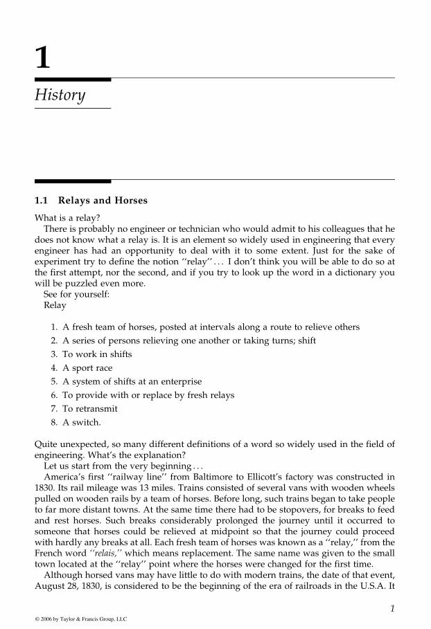
1.1 Relays and Horses
What is a relay?There is probably no engineer or technician who would admit to his colleagues that he
does not know what a relay is. It is an element so widely used in engineering that everyengineer has had an opportunity to deal with it to some extent. Just for the sake ofexperiment try to define the notion ‘‘relay’’ . . . I don’t think you will be able to do so atthe first attempt, nor the second, and if you try to look up the word in a dictionary youwill be puzzled even more.
See for yourself:Relay
1. A fresh team of horses, posted at intervals along a route to relieve others
2. A series of persons relieving one another or taking turns; shift
3. To work in shifts
4. A sport race
5. A system of shifts at an enterprise
6. To provide with or replace by fresh relays
7. To retransmit
8. A switch.
Quite unexpected, so many different definitions of a word so widely used in the field ofengineering. What’s the explanation?
Let us start from the very beginning . . .America’s first ‘‘railway line’’ from Baltimore to Ellicott’s factory was constructed in
1830. Its rail mileage was 13 miles. Trains consisted of several vans with wooden wheelspulled on wooden rails by a team of horses. Before long, such trains began to take peopleto far more distant towns. At the same time there had to be stopovers, for breaks to feedand rest horses. Such breaks considerably prolonged the journey until it occurred tosomeone that horses could be relieved at midpoint so that the journey could proceedwith hardly any breaks at all. Each fresh team of horses was known as a ‘‘relay,’’ from theFrench word ‘‘relais,’’ which means replacement. The same name was given to the smalltown located at the ‘‘relay’’ point where the horses were changed for the first time.
Although horsed vans may have little to do with modern trains, the date of that event,August 28, 1830, is considered to be the beginning of the era of railroads in the U.S.A. It
GUREVICH / Electric Relays: Principles and Practises DK884X_c001 Final Proof page 1 29.10.2005 10:55pm
1© 2006 by Taylor & Francis Group, LLC
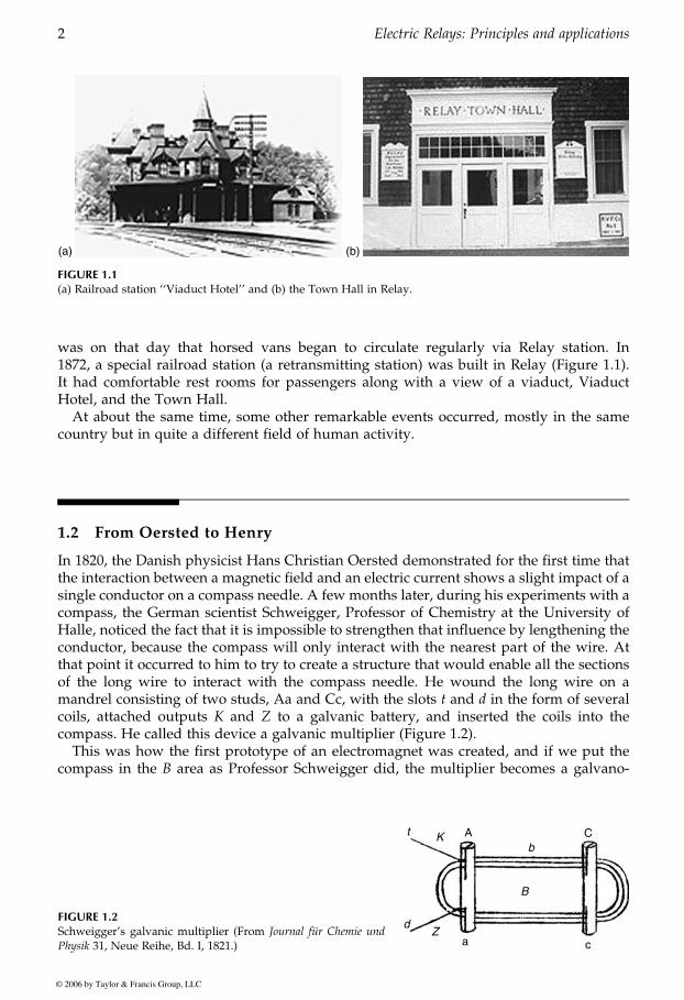
was on that day that horsed vans began to circulate regularly via Relay station. In1872, a special railroad station (a retransmitting station) was built in Relay (Figure 1.1).It had comfortable rest rooms for passengers along with a view of a viaduct, ViaductHotel, and the Town Hall.
At about the same time, some other remarkable events occurred, mostly in the samecountry but in quite a different field of human activity.
1.2 From Oersted to Henry
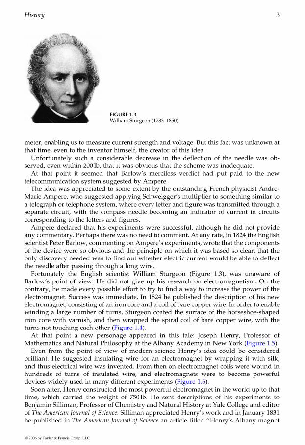
In 1820, the Danish physicist Hans Christian Oersted demonstrated for the first time thatthe interaction between a magnetic field and an electric current shows a slight impact of asingle conductor on a compass needle. A few months later, during his experiments with acompass, the German scientist Schweigger, Professor of Chemistry at the University ofHalle, noticed the fact that it is impossible to strengthen that influence by lengthening theconductor, because the compass will only interact with the nearest part of the wire. Atthat point it occurred to him to try to create a structure that would enable all the sectionsof the long wire to interact with the compass needle. He wound the long wire on amandrel consisting of two studs, Aa and Cc, with the slots t and d in the form of severalcoils, attached outputs K and Z to a galvanic battery, and inserted the coils into thecompass. He called this device a galvanic multiplier (Figure 1.2).
This was how the first prototype of an electromagnet was created, and if we put thecompass in the B area as Professor Schweigger did, the multiplier becomes a galvano-
(a) (b)
FIGURE 1.1(a) Railroad station ‘‘Viaduct Hotel’’ and (b) the Town Hall in Relay.
FIGURE 1.2Schweigger’s galvanic multiplier (From Journal fur Chemie und
Physik 31, Neue Reihe, Bd. I, 1821.)
t K A
B
dZ
a c
Cb
GUREVICH / Electric Relays: Principles and Practises DK884X_c001 Final Proof page 2 29.10.2005 10:55pm
2 Electric Relays: Principles and applications
© 2006 by Taylor & Francis Group, LLC
meter, enabling us to measure current strength and voltage. But this fact was unknown atthat time, even to the inventor himself, the creator of this idea.
Unfortunately such a considerable decrease in the deflection of the needle was ob-served, even within 200 lb, that it was obvious that the scheme was inadequate.
At that point it seemed that Barlow’s merciless verdict had put paid to the newtelecommunication system suggested by Ampere.
The idea was appreciated to some extent by the outstanding French physicist Andre-Marie Ampere, who suggested applying Schweigger’s multiplier to something similar toa telegraph or telephone system, where every letter and figure was transmitted through aseparate circuit, with the compass needle becoming an indicator of current in circuitscorresponding to the letters and figures.
Ampere declared that his experiments were successful, although he did not provideany commentary. Perhaps there was no need to comment. At any rate, in 1824 the Englishscientist Peter Barlow, commenting on Ampere’s experiments, wrote that the componentsof the device were so obvious and the principle on which it was based so clear, that theonly discovery needed was to find out whether electric current would be able to deflectthe needle after passing through a long wire.
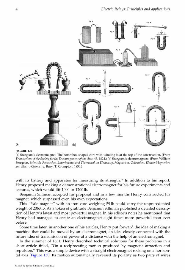
Fortunately the English scientist William Sturgeon (Figure 1.3), was unaware ofBarlow’s point of view. He did not give up his research on electromagnetism. On thecontrary, he made every possible effort to try to find a way to increase the power of theelectromagnet. Success was immediate. In 1824 he published the description of his newelectromagnet, consisting of an iron core and a coil of bare copper wire. In order to enablewinding a large number of turns, Sturgeon coated the surface of the horseshoe-shapediron core with varnish, and then wrapped the spiral coil of bare copper wire, with the
At that point a new personage appeared in this tale: Joseph Henry, Professor of
Even from the point of view of modern science Henry’s idea could be consideredbrilliant. He suggested insulating wire for an electromagnet by wrapping it with silk,and thus electrical wire was invented. From then on electromagnet coils were wound inhundreds of turns of insulated wire, and electromagnets were to become powerful
Soon after, Henry constructed the most powerful electromagnet in the world up to thattime, which carried the weight of 750 lb. He sent descriptions of his experiments toBenjamin Silliman, Professor of Chemistry and Natural History at Yale College and editorof The American Journal of Science. Silliman appreciated Henry’s work and in January 1831he published in The American Journal of Science an article titled ‘‘Henry’s Albany magnet
FIGURE 1.3William Sturgeon (1783–1850).
GUREVICH / Electric Relays: Principles and Practises DK884X_c001 Final Proof page 3 29.10.2005 10:55pm
History 3
© 2006 by Taylor & Francis Group, LLC
turns not touching each other (Figure 1.4).
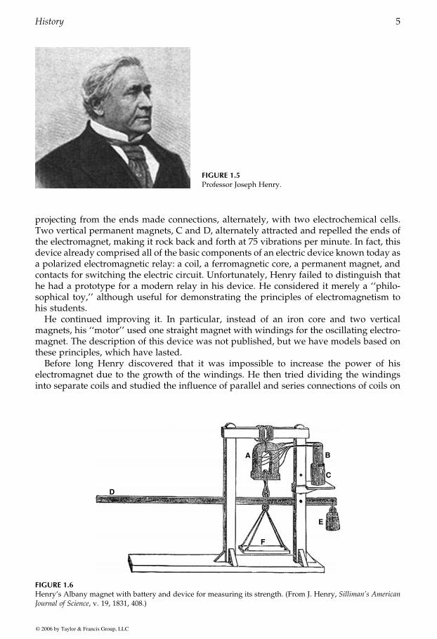
Mathematics and Natural Philosophy at the Albany Academy in New York (Figure 1.5).
devices widely used in many different experiments (Figure 1.6).
with its battery and apparatus for measuring its strength.’’ In addition to his report,Henry proposed making a demonstrational electromagnet for his future experiments andlectures, which would lift 1000 or 1200 lb.
Benjamin Silliman accepted his proposal and in a few months Henry constructed hismagnet, which surpassed even his own expectations.
This ‘‘Yale magnet’’ with an iron core weighing 59 lb could carry the unprecedentedweight of 2063 lb. As a token of gratitude Benjamin Silliman published a detailed descrip-tion of Henry’s latest and most powerful magnet. In his editor’s notes he mentioned thatHenry had managed to create an electromagnet eight times more powerful than everbefore.
Some time later, in another one of his articles, Henry put forward the idea of making amachine that could be moved by an electromagnet, an idea closely connected with thefuture idea of transmission of power at a distance with the help of an electromagnet.
In the summer of 1831, Henry described technical solutions for these problems in ashort article titled, ‘‘On a reciprocating motion produced by magnetic attraction andrepulsion.’’ This was a simple device with a straight electromagnet rocking on a horizon-
(b)
d
(a)
FIGURE 1.4(a) Sturgeon’s electromagnet. The horseshoe-shaped core with winding is at the top of the construction. (FromTransactions of the Society for the Encouragement of the Arts, 43, 1824.) (b) Sturgeon’s electromagnets. (FromWilliamSturgeon, Scientific Researches, Experimental and Theoretical, in Electricity, Magnetism, Galvanism, Electro-Magnetismand Electro-Chemistry, Bury, T. Crompton, 1850.)
GUREVICH / Electric Relays: Principles and Practises DK884X_c001 Final Proof page 4 29.10.2005 10:55pm
4 Electric Relays: Principles and applications
© 2006 by Taylor & Francis Group, LLC
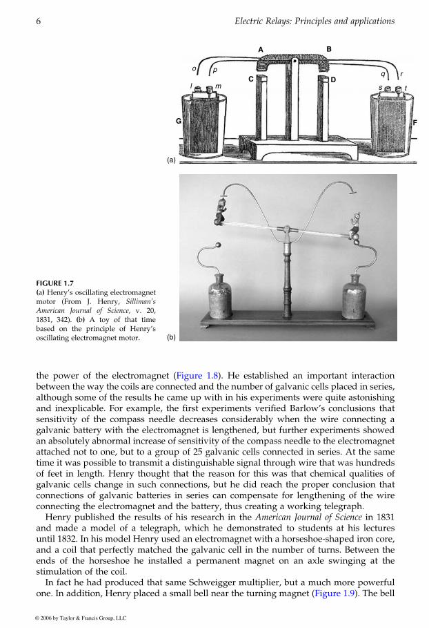
tal axis (Figure 1.7). Its motion automatically reversed its polarity as two pairs of wires
projecting from the ends made connections, alternately, with two electrochemical cells.Two vertical permanent magnets, C and D, alternately attracted and repelled the ends ofthe electromagnet, making it rock back and forth at 75 vibrations per minute. In fact, thisdevice already comprised all of the basic components of an electric device known today asa polarized electromagnetic relay: a coil, a ferromagnetic core, a permanent magnet, andcontacts for switching the electric circuit. Unfortunately, Henry failed to distinguish thathe had a prototype for a modern relay in his device. He considered it merely a ‘‘philo-sophical toy,’’ although useful for demonstrating the principles of electromagnetism tohis students.
He continued improving it. In particular, instead of an iron core and two verticalmagnets, his ‘‘motor’’ used one straight magnet with windings for the oscillating electro-magnet. The description of this device was not published, but we have models based onthese principles, which have lasted.
Before long Henry discovered that it was impossible to increase the power of hiselectromagnet due to the growth of the windings. He then tried dividing the windingsinto separate coils and studied the influence of parallel and series connections of coils on
FIGURE 1.5Professor Joseph Henry.
D
A B
C
E
F
FIGURE 1.6Henry’s Albany magnet with battery and device for measuring its strength. (From J. Henry, Silliman’s American
Journal of Science, v. 19, 1831, 408.)
GUREVICH / Electric Relays: Principles and Practises DK884X_c001 Final Proof page 5 29.10.2005 10:55pm
History 5
© 2006 by Taylor & Francis Group, LLC
between the way the coils are connected and the number of galvanic cells placed in series,although some of the results he came up with in his experiments were quite astonishingand inexplicable. For example, the first experiments verified Barlow’s conclusions thatsensitivity of the compass needle decreases considerably when the wire connecting agalvanic battery with the electromagnet is lengthened, but further experiments showedan absolutely abnormal increase of sensitivity of the compass needle to the electromagnetattached not to one, but to a group of 25 galvanic cells connected in series. At the sametime it was possible to transmit a distinguishable signal through wire that was hundredsof feet in length. Henry thought that the reason for this was that chemical qualities ofgalvanic cells change in such connections, but he did reach the proper conclusion thatconnections of galvanic batteries in series can compensate for lengthening of the wireconnecting the electromagnet and the battery, thus creating a working telegraph.
Henry published the results of his research in the American Journal of Science in 1831and made a model of a telegraph, which he demonstrated to students at his lecturesuntil 1832. In his model Henry used an electromagnet with a horseshoe-shaped iron core,and a coil that perfectly matched the galvanic cell in the number of turns. Between theends of the horseshoe he installed a permanent magnet on an axle swinging at thestimulation of the coil.
In fact he had produced that same Schweigger multiplier, but a much more powerful
FIGURE 1.7(a) Henry’s oscillating electromagnetmotor (From J. Henry, Silliman’s
American Journal of Science, v. 20,1831, 342). (b) A toy of that timebased on the principle of Henry’soscillating electromagnet motor.
C Dq r
s t
o p
ml
G F
A B
(a)
(b)
GUREVICH / Electric Relays: Principles and Practises DK884X_c001 Final Proof page 6 29.10.2005 10:55pm
6 Electric Relays: Principles and applications
© 2006 by Taylor & Francis Group, LLC
the power of the electromagnet (Figure 1.8). He established an important interaction
one. In addition, Henry placed a small bell near the turning magnet (Figure 1.9). The bell

rang every time the magnet hit it. The electromagnet was attached to the battery with thehelp of copper wire about a mile in length, which was drawn through the lecture hall.
Joseph Henry became more and more popular in the American scientific community. In1832 he was named Professor of Natural Philosophy at Princeton College. He restored hismodel of the telegraph, but this time the wire was drawn not in a lecture hall, but betweencampuses. Considering his teaching as foremost to conducting research, Henry createdmore and more new models for his lectures.
In 1835 he decided to combine his sensitive telegraph electromagnet. Working from aremote battery his superpower magnet lifted a record weight supplied by a powerfulbattery. In this new construction, instead of using a bell as in his telegraph, a permanentturning magnet closed contacts and connected the powerful electromagnet into thecircuit.
As you may have guessed, this was the very first relay in the world. But neither Henry northe others knew that it was a relay. Professor Henry enthusiastically demonstrated hisnew ‘‘toy’’ to his students: first he would turn on the whole system and fix a heavy weighton the electromagnet, then he turned it off from a long distance by means of the sensitivetelegraph electromagnet. The turning electromagnet broke the supply circuit of thepowerful electromagnet and the heavy weight came hurtling down followed by students’enthusiastic exclamations. Being far from practical, Professor Henry told students aboutprospects of his new device to be used for remote control of bells in churches, but it wasnot only his students who knew about his advances. Some famous and less famous
FIGURE 1.8Henry’s electromagnet with separate windings connected in series orparallel.
(a) (b)
FIGURE 1.9(a) A demonstrational model and (b) a later model of the receiving apparatus of Henry’s telegraph, constructedin 1831.
GUREVICH / Electric Relays: Principles and Practises DK884X_c001 Final Proof page 7 29.10.2005 10:55pm
History 7
© 2006 by Taylor & Francis Group, LLC
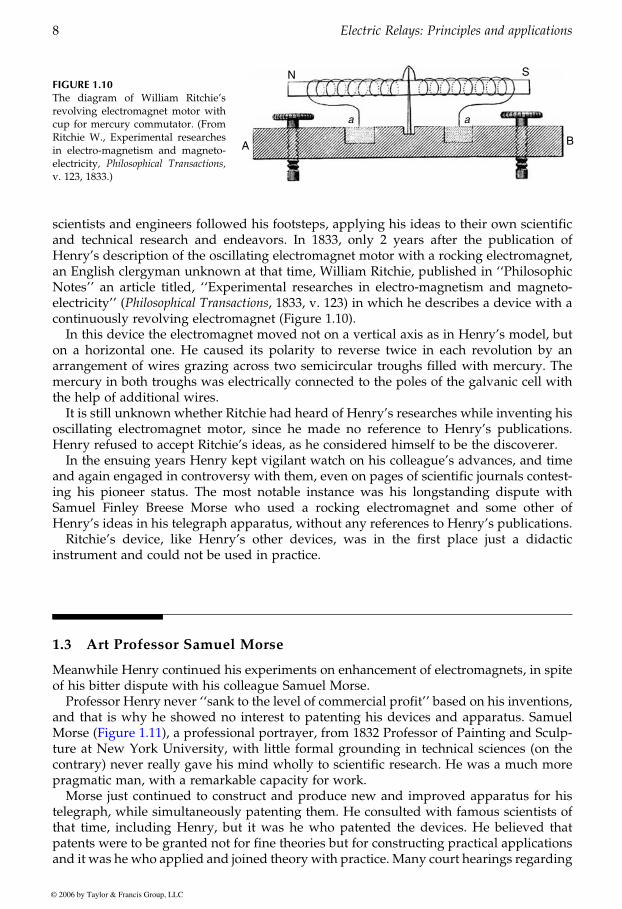
scientists and engineers followed his footsteps, applying his ideas to their own scientificand technical research and endeavors. In 1833, only 2 years after the publication ofHenry’s description of the oscillating electromagnet motor with a rocking electromagnet,an English clergyman unknown at that time, William Ritchie, published in ‘‘PhilosophicNotes’’ an article titled, ‘‘Experimental researches in electro-magnetism and magneto-electricity’’ (Philosophical Transactions, 1833, v. 123) in which he describes a device with acontinuously revolving electromagnet (Figure 1.10).
In this device the electromagnet moved not on a vertical axis as in Henry’s model, buton a horizontal one. He caused its polarity to reverse twice in each revolution by anarrangement of wires grazing across two semicircular troughs filled with mercury. Themercury in both troughs was electrically connected to the poles of the galvanic cell withthe help of additional wires.
It is still unknown whether Ritchie had heard of Henry’s researches while inventing hisoscillating electromagnet motor, since he made no reference to Henry’s publications.Henry refused to accept Ritchie’s ideas, as he considered himself to be the discoverer.
In the ensuing years Henry kept vigilant watch on his colleague’s advances, and timeand again engaged in controversy with them, even on pages of scientific journals contest-ing his pioneer status. The most notable instance was his longstanding dispute withSamuel Finley Breese Morse who used a rocking electromagnet and some other ofHenry’s ideas in his telegraph apparatus, without any references to Henry’s publications.
Ritchie’s device, like Henry’s other devices, was in the first place just a didacticinstrument and could not be used in practice.
1.3 Art Professor Samuel Morse
Meanwhile Henry continued his experiments on enhancement of electromagnets, in spiteof his bitter dispute with his colleague Samuel Morse.
Professor Henry never ‘‘sank to the level of commercial profit’’ based on his inventions,and that is why he showed no interest to patenting his devices and apparatus. Samuel
ture at New York University, with little formal grounding in technical sciences (on thecontrary) never really gave his mind wholly to scientific research. He was a much morepragmatic man, with a remarkable capacity for work.
Morse just continued to construct and produce new and improved apparatus for histelegraph, while simultaneously patenting them. He consulted with famous scientists ofthat time, including Henry, but it was he who patented the devices. He believed thatpatents were to be granted not for fine theories but for constructing practical applicationsand it was he who applied and joined theory with practice. Many court hearings regarding
FIGURE 1.10The diagram of William Ritchie’srevolving electromagnet motor withcup for mercury commutator. (FromRitchie W., Experimental researchesin electro-magnetism and magneto-electricity, Philosophical Transactions,v. 123, 1833.)
a a
GUREVICH / Electric Relays: Principles and Practises DK884X_c001 Final Proof page 8 29.10.2005 10:55pm
8 Electric Relays: Principles and applications
© 2006 by Taylor & Francis Group, LLC
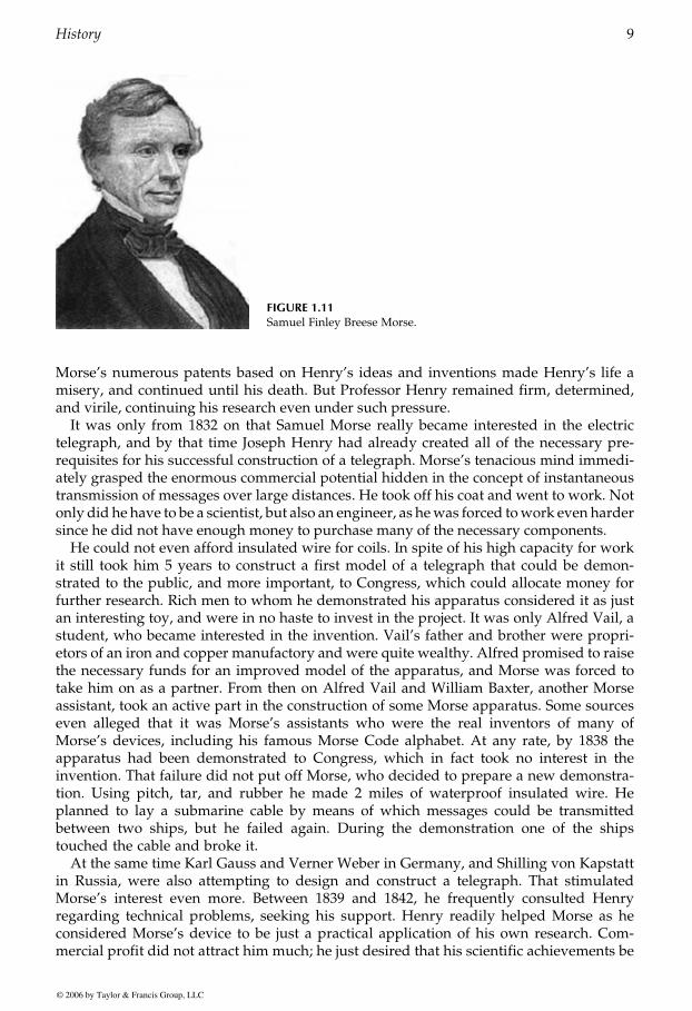
Morse (Figure 1.11), a professional portrayer, from 1832 Professor of Painting and Sculp-
Morse’s numerous patents based on Henry’s ideas and inventions made Henry’s life amisery, and continued until his death. But Professor Henry remained firm, determined,and virile, continuing his research even under such pressure.
It was only from 1832 on that Samuel Morse really became interested in the electrictelegraph, and by that time Joseph Henry had already created all of the necessary pre-requisites for his successful construction of a telegraph. Morse’s tenacious mind immedi-ately grasped the enormous commercial potential hidden in the concept of instantaneoustransmission of messages over large distances. He took off his coat and went to work. Notonly did he have to be a scientist, but also an engineer, as hewas forced towork even hardersince he did not have enough money to purchase many of the necessary components.
He could not even afford insulated wire for coils. In spite of his high capacity for workit still took him 5 years to construct a first model of a telegraph that could be demon-strated to the public, and more important, to Congress, which could allocate money forfurther research. Rich men to whom he demonstrated his apparatus considered it as justan interesting toy, and were in no haste to invest in the project. It was only Alfred Vail, astudent, who became interested in the invention. Vail’s father and brother were propri-etors of an iron and copper manufactory and were quite wealthy. Alfred promised to raisethe necessary funds for an improved model of the apparatus, and Morse was forced totake him on as a partner. From then on Alfred Vail and William Baxter, another Morseassistant, took an active part in the construction of some Morse apparatus. Some sourceseven alleged that it was Morse’s assistants who were the real inventors of many ofMorse’s devices, including his famous Morse Code alphabet. At any rate, by 1838 theapparatus had been demonstrated to Congress, which in fact took no interest in theinvention. That failure did not put off Morse, who decided to prepare a new demonstra-tion. Using pitch, tar, and rubber he made 2 miles of waterproof insulated wire. Heplanned to lay a submarine cable by means of which messages could be transmittedbetween two ships, but he failed again. During the demonstration one of the shipstouched the cable and broke it.
At the same time Karl Gauss and Verner Weber in Germany, and Shilling von Kapstattin Russia, were also attempting to design and construct a telegraph. That stimulatedMorse’s interest even more. Between 1839 and 1842, he frequently consulted Henryregarding technical problems, seeking his support. Henry readily helped Morse as heconsidered Morse’s device to be just a practical application of his own research. Com-mercial profit did not attract him much; he just desired that his scientific achievements be
FIGURE 1.11Samuel Finley Breese Morse.
GUREVICH / Electric Relays: Principles and Practises DK884X_c001 Final Proof page 9 29.10.2005 10:56pm
History 9
© 2006 by Taylor & Francis Group, LLC
implemented in practice and that is what he expected from Morse. In February 1842,making use of his reputation and influence, he appealed to Congress to assist Morse infunding his project.
Later on that same year (1842), after Henry’s appeal, Morse succeeded in gaining thesupport of Congress and was able to obtain $30,000. In May 1844, he successfullydemonstrated his telegraph to the public. ‘‘What hath God wrought?’’ was the firstmessage officially transmitted by telegraph. The daughter of the Head of the PatentAuthority had chosen that message.
Twelve years of hard work were crowned with triumph and international fame, andMorse was acknowledged as the inventor of this new means of communication. Unfor-tunately, he did not acknowledge Henry’s contribution to the invention in his publica-tions and patents, and this greatly soured the relations between them.
As a result, Morse and Henry became involved in a long series of litigations, and wereto continue struggling for what each considered his rights, until their deaths.
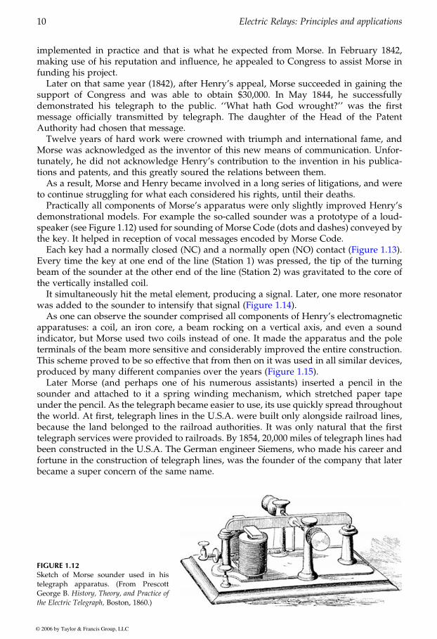
Practically all components of Morse’s apparatus were only slightly improved Henry’sdemonstrational models. For example the so-called sounder was a prototype of a loud-speaker (see Figure 1.12) used for sounding of Morse Code (dots and dashes) conveyed bythe key. It helped in reception of vocal messages encoded by Morse Code.
Every time the key at one end of the line (Station 1) was pressed, the tip of the turningbeam of the sounder at the other end of the line (Station 2) was gravitated to the core ofthe vertically installed coil.
It simultaneously hit the metal element, producing a signal. Later, one more resonator
As one can observe the sounder comprised all components of Henry’s electromagneticapparatuses: a coil, an iron core, a beam rocking on a vertical axis, and even a soundindicator, but Morse used two coils instead of one. It made the apparatus and the poleterminals of the beam more sensitive and considerably improved the entire construction.This scheme proved to be so effective that from then on it was used in all similar devices,
Later Morse (and perhaps one of his numerous assistants) inserted a pencil in thesounder and attached to it a spring winding mechanism, which stretched paper tapeunder the pencil. As the telegraph became easier to use, its use quickly spread throughoutthe world. At first, telegraph lines in the U.S.A. were built only alongside railroad lines,because the land belonged to the railroad authorities. It was only natural that the firsttelegraph services were provided to railroads. By 1854, 20,000 miles of telegraph lines hadbeen constructed in the U.S.A. The German engineer Siemens, who made his career andfortune in the construction of telegraph lines, was the founder of the company that laterbecame a super concern of the same name.
FIGURE 1.12Sketch of Morse sounder used in histelegraph apparatus. (From PrescottGeorge B. History, Theory, and Practice of
the Electric Telegraph, Boston, 1860.)
GUREVICH / Electric Relays: Principles and Practises DK884X_c001 Final Proof page 10 29.10.2005 10:56pm
10 Electric Relays: Principles and applications
© 2006 by Taylor & Francis Group, LLC
Each key had a normally closed (NC) and a normally open (NO) contact (Figure 1.13).
was added to the sounder to intensify that signal (Figure 1.14).
produced by many different companies over the years (Figure 1.15).
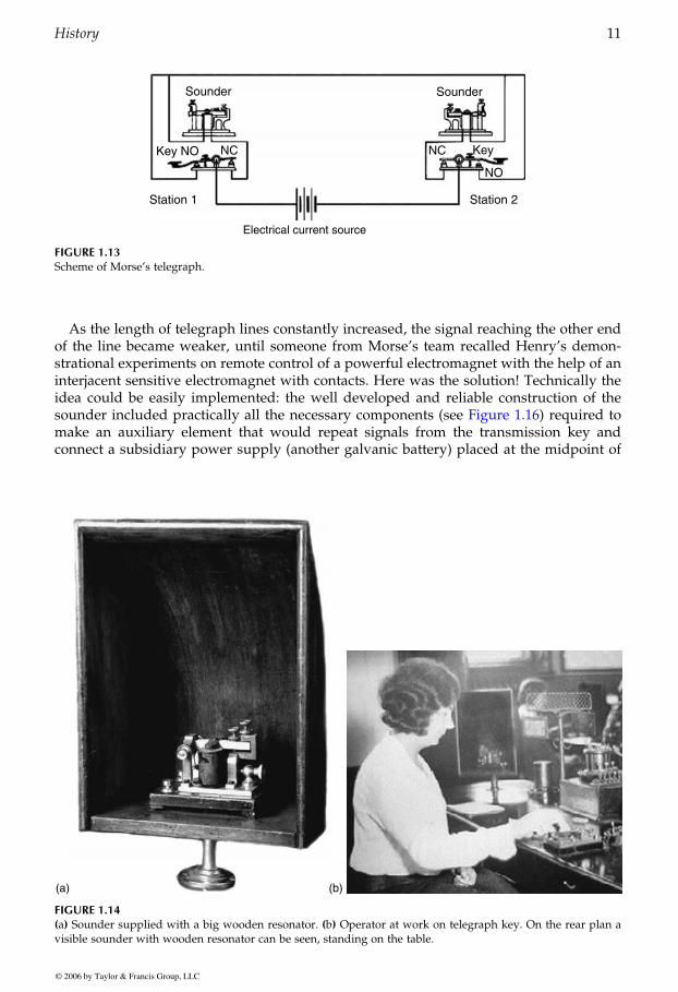
As the length of telegraph lines constantly increased, the signal reaching the other endof the line became weaker, until someone from Morse’s team recalled Henry’s demon-strational experiments on remote control of a powerful electromagnet with the help of aninterjacent sensitive electromagnet with contacts. Here was the solution! Technically theidea could be easily implemented: the well developed and reliable construction of the
make an auxiliary element that would repeat signals from the transmission key andconnect a subsidiary power supply (another galvanic battery) placed at the midpoint of
Electrical current source
FIGURE 1.13Scheme of Morse’s telegraph.
(a) (b)
FIGURE 1.14(a) Sounder supplied with a big wooden resonator. (b) Operator at work on telegraph key. On the rear plan avisible sounder with wooden resonator can be seen, standing on the table.
GUREVICH / Electric Relays: Principles and Practises DK884X_c001 Final Proof page 11 29.10.2005 10:56pm
History 11
© 2006 by Taylor & Francis Group, LLC
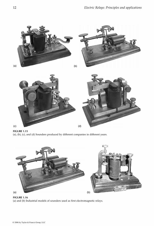
sounder included practically all the necessary components (see Figure 1.16) required to
(a) (b)
(c) (d)
FIGURE 1.15(a), (b), (c), and (d) Sounders produced by different companies in different years.
(a) (b)
FIGURE 1.16(a) and (b) Industrial models of sounders used as first electromagnetic relays.
GUREVICH / Electric Relays: Principles and Practises DK884X_c001 Final Proof page 12 29.10.2005 10:56pm
12 Electric Relays: Principles and applications
© 2006 by Taylor & Francis Group, LLC
the line, in time with the signals. Long distances between transmitting and receivingstations were no longer a problem as one or even several repeaters of the signal with‘‘full’’ batteries could be installed on different telegraph stations.
At first such devices were called ‘‘repeaters’’ and ‘‘registers’’ but then someone noticedthat the functions of such devices in the telegraph were similar to those of ‘‘relay stations’’where horses were relieved. Such devices replaced a weak signal (run-down horses) witha more powerful one, connecting a ‘‘full’’ battery (another horse) at the midpoint of theline. As the term ‘‘relay’’ gradually caught on, it replaced all of the previously used terms.
Relays began to develop rapidly. New brands appeared, multiplying like clones. Moreand more companies began to specialize in the construction and production of relays
1.4 Edison’s Relay
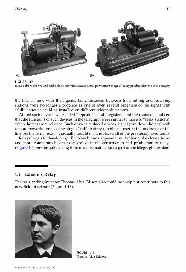
The outstanding inventor Thomas Alva Edison also could not help but contribute to thisnew field of science (Figure 1.18).
(a) (b)
FIGURE 1.17(a) and (b)Multi-wound andpolarized (with an additional permanentmagnet) relay produced in the 19th century.
FIGURE 1.18Thomas Alva Edison.
GUREVICH / Electric Relays: Principles and Practises DK884X_c001 Final Proof page 13 29.10.2005 10:56pm
History 13
© 2006 by Taylor & Francis Group, LLC
(Figure 1.7) but for quite a long time relays remained just a part of the telegraphic system.
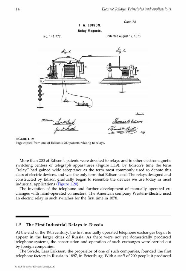
More than 200 of Edison’s patents were devoted to relays and to other electromagneticswitching centers of telegraph apparatuses (Figure 1.19). By Edison’s time the term‘‘relay’’ had gained wide acceptance as the term most commonly used to denote thisclass of electric devices, and was the only term that Edison used. The relays designed andconstructed by Edison gradually began to resemble the devices we use today in most
The invention of the telephone and further development of manually operated ex-changes with hand-operated connectors; The American company Western-Electric usedan electric relay in such switches for the first time in 1878.
1.5 The First Industrial Relays in Russia
At the end of the 19th century, the first manually operated telephone exchanges began toappear in the larger cities of Russia. As there were not yet domestically producedtelephone systems, the construction and operation of such exchanges were carried outby foreign companies.
The Swede, Lars Eriksson, the proprietor of one of such companies, founded the firsttelephone factory in Russia in 1897, in Petersburg. With a staff of 200 people it produced
No. 141,777. Patented August 12, 1873.
T. A. EDISON.
Relay Magnets.
Case 73.
FIGURE 1.19Page copied from one of Edison’s 200 patents relating to relays.
GUREVICH / Electric Relays: Principles and Practises DK884X_c001 Final Proof page 14 29.10.2005 10:56pm
14 Electric Relays: Principles and applications
© 2006 by Taylor & Francis Group, LLC
industrial applications (Figure 1.20).
12,000 telephone sets and about 100 switches over a period of 4 years. Later on it increasedits capacity to produce over 60,000 telephone sets and a few hundreds of switchesannually.
During the Russian–Japanese war the factory first began to produce military goods:field stations with phonic calls and outpost telephones. On January 1, 1905, it wasrenamed ‘‘The Russian Incorporated Company, L. Eriksson and Co.’’
When the First World War broke out, two more departments — naval and technical —were opened there for scientific and technical research. By 1915 the factory had evolvedinto a large plant, with a staff of more than 3000 people. The plant used mostly Swedishcomponents for assembly of the various items it produced, among which were also relays.
In 1919, the plant was nationalized and transferred to the state-owned enterprises ofweak-current electric industry. In 1922 the plant was renamed the Petrograd Telephoneplant ‘‘Krasnaya Zarya’’ and joined the State Trust of weak-current electric plants (calledthe 9th Central Administrative Board of Ministry of Communication Industry in theclosing stages of the Soviet Union), which also included the other 11 companies of theU.S.S.R. This marked the beginning of production of telephone relays in Russia.
The first models of relays, produced by ‘‘Krasnaya Zarya’’ until 1925, were of the
(a) (b)
(c)
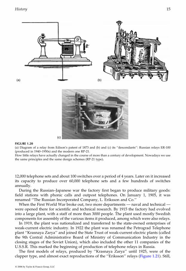
FIGURE 1.20(a) Diagram of a relay from Edison’s patent of 1873 and (b) and (c) its ‘‘descendants’’: Russian relays ER-100(produced in 1940–1950s) and the modern one RP-21.How little relays have actually changed in the course of more than a century of development. Nowadays we usethe same principles and the same design schemes (RP-21 type).
GUREVICH / Electric Relays: Principles and Practises DK884X_c001 Final Proof page 15 29.10.2005 10:56pm
History 15
© 2006 by Taylor & Francis Group, LLC
clapper type, and almost exact reproductions of the ‘‘Eriksson’’ relays (Figure 1.21). Still,
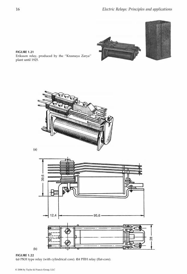
FIGURE 1.21Eriksson relay, produced by the ‘‘Krasnaya Zarya’’plant until 1925.
(a)
(b)
FIGURE 1.22(a) PKH type relay (with cylindrical core). (b) PPH relay (flat-core).
GUREVICH / Electric Relays: Principles and Practises DK884X_c001 Final Proof page 16 29.10.2005 10:56pm
16 Electric Relays: Principles and applications
© 2006 by Taylor & Francis Group, LLC

they were produced manually, in small series, and the materials for their production camefrom abroad.
Due to their lack of experience, Russian scientists at first attempted to obtain generalknowledge and experience regarding the most common relay designs in use at that timearound the world.
In 1934, Professor Matov of The Moscow Institute of Energy published the bookTelephone Relays, their Construction and Design, which was the first Russian publication topresent general knowledge and experience from around the world in the design ofelectromagnetic relays.
Being aware of Russia’s technological gap, and realizing the importance of develop-ment of relay devices for modern communication and automation systems, the People’sCommissariat of the Defense Industry created the Scientific-Research Institute of Electro-mechanics.
One of its main tasks was the invention and development of new types of relays fordifferent fields of application, including defense technology. The Head of research was B.Sotskov. At the same time, in 1928, the Kharkov Electromechanical Plant began toproduce relays for the power-generation industry and the electric drive industry. In afew years it was able to produce several different types of such relays, though stillreproducing the best examples of foreign equipment. That policy lasted many longyears. Copies of new German relays taken from captured German V-2 rockets were
millions since 1946 were only copies of German and English relays.It is interesting to note that although those relays were not used in telephone and
telecommunication equipment, they ‘‘were revived’’ in systems of relay protectionof electric networks. One of the biggest and most famous concerns producing allkinds of technical equipment for the power-generation industry still produces and utili-zes analogs of RKH relays Of course these relays are made todayusing new materials (they have a winding for 220 V of continuous current and contain99,000 turns of 0.056 mm wire with a coil resistance of 39 kV). Also, today’s model comeswith a nice-looking transparent case, but that does not change the fact that it is still quitean ancient device.
The number of relay plants grew rapidly. Weak-current relays were then produced inKharkov (by the production association ‘‘Radiorele’’), S. Petersburg (by the research-and-production association ‘‘Severnaya zarya’’), Irkutsk, Alatyr, Porhov, Krasnodon, Penza,and in many other cities.
About that same time there were many plants producing larger industrial relays (theelectric equipment plant in Cheboksary, the production association of ‘‘Automation andRelays’’ in Kiev, the production association of electric equipment in Tiraspol, electricequipment plants in Moscow and Yerevan, etc.) and some plants that produced aircraft
FIGURE 1.23The modern relay RXMA-1 produced by the concernABB, one of the world leaders in the relay field, is apractically identical copy of the PKH type relay and its‘‘predecessors.’’
GUREVICH / Electric Relays: Principles and Practises DK884X_c001 Final Proof page 17 29.10.2005 10:56pm
History 17
© 2006 by Taylor & Francis Group, LLC
especially popular at that time. PKH and PPH type relays (Figure 1.22) produced in
1.23).(Figure
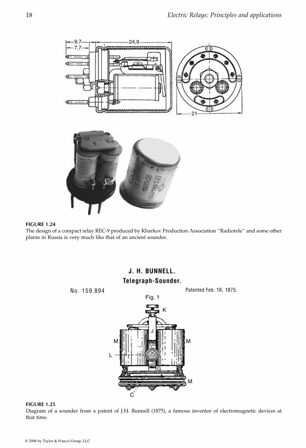
FIGURE 1.24The design of a compact relay REC-9 produced by Kharkov Production Association ‘‘Radiorele’’ and some otherplants in Russia is very much like that of an ancient sounder.
FIGURE 1.25Diagram of a sounder from a patent of J.H. Bunnell (1875), a famous inventor of electromagnetic devices atthat time.
GUREVICH / Electric Relays: Principles and Practises DK884X_c001 Final Proof page 18 29.10.2005 10:56pm
18 Electric Relays: Principles and applications
© 2006 by Taylor & Francis Group, LLC

switching equipment. In order to coordinate scientific activities in the field and to supportthe production of relays, the Scientific Research Institute of Switching Equipment, spe-cializing in weak-current relays, was created in Leningrad, the All-Union ScientificResearch Institute of the Relay Construction specializing in industrial automation relaysand protective relays for the power-generation industry, in Cheboksary, and the CentralScientific Research Institute Number-22, coordinating researches in relay equipment fordefense industry in Mytishi, situated near Moscow.
In the final stages of the U.S.S.R., relays were produced by dozens of big plantsbelonging to three Ministries: the Ministry of Communication Industry, the Ministry ofElectrical Industry, and the Ministry of Aircraft Industry.
Today the range of types of electromagnetic relays produced by plants of the formerSoviet Union is quite wide. It is possible, for instance, to come across REC-9 type relays,which used to be regularly produced by Kharkov Production Association ‘‘Radiorele’’
relay, applied in all fields of engineering. The author even happened to come across suchrelays in a reentry missile vehicle 9K21, fitting all types of charges.
The Irkutsk Relay Plant still continues producing such ‘‘veteran’’ relay devices, as theMKU-48 (Figure 1.26), which are in fact to be placed in a museum of technical equipmenthistory.
Today Russian plants also produce many quite up-to-date relays, corresponding totheir foreign analogs (Figure 1.27).
FIGURE 1.26Out-of-date MKU-48 type relay for automation industrysystems still produced by the Irkutsk Relay Plant.
FIGURE 1.27Modern Russian relays.
GUREVICH / Electric Relays: Principles and Practises DK884X_c001 Final Proof page 19 29.10.2005 10:56pm
History 19
© 2006 by Taylor & Francis Group, LLC
(Figure 1.24). The magnetic system of this two-coil relay is quite similar to many ancientsounders of the 19th century (Figure 1.25). Nevertheless, it was quite a reliable universal

2Magnetic Systems of Relays
2.1 Basic Components of an Electromagnetic Relay
An electromagnetic neutral relay is the simplest, most ancient, and widespread type ofrelay. What are its basic elements? As a rule, most people asked this question wouldprobably name the following: a winding, a magnetic core, an armature, a spring, andcontacts.
This all is true of course, but if you begin to analyze how a relay works, it might occur toyou that something is missing. What is the purpose of a magnetic system? Apparently it isused to transform input electric current to the mechanical power needed for contactclosure. And what does a contact system do? It transforms the imparted mechanicalpower back to an electric signal.
Don’t you think that something is wrong here?Everything will become more obvious if the list of basic components of a relay includes
one more element, which is not so obvious from the point of view of the construction of arelay, for example, a coil or contacts. Very often, it is not just one element, but severalsmall parts, that escape our attention. Such parts are often omitted on diagrams illustrat-ing the principle of relay operation (Figure 2.1). I am referring to an insulation systemproviding galvanic isolation of the input circuit (winding) from output one (contacts). Ifwe take such an insulation system into account, it becomes clear that an input signal at therelay input and the output signal at the relay output are not the same. They are twodifferent signals that are completely insulated from each other electrically. Note that ifyou use Figure 2.1, which is often used to illustrate principles of relay operation, as the
� �
d
FIGURE 2.1Construction of a simple electromagnetic relay.1 — springs; 2 — contacts; 3 — armature; 4 — core;5 — winding; 6 — magnetic core; 7 — insulator.
GUREVICH / Electric Relays: Principles and Practises DK884X_c002 Final Proof page 21 31.10.2005 8:37am
21© 2006 by Taylor & Francis Group, LLC
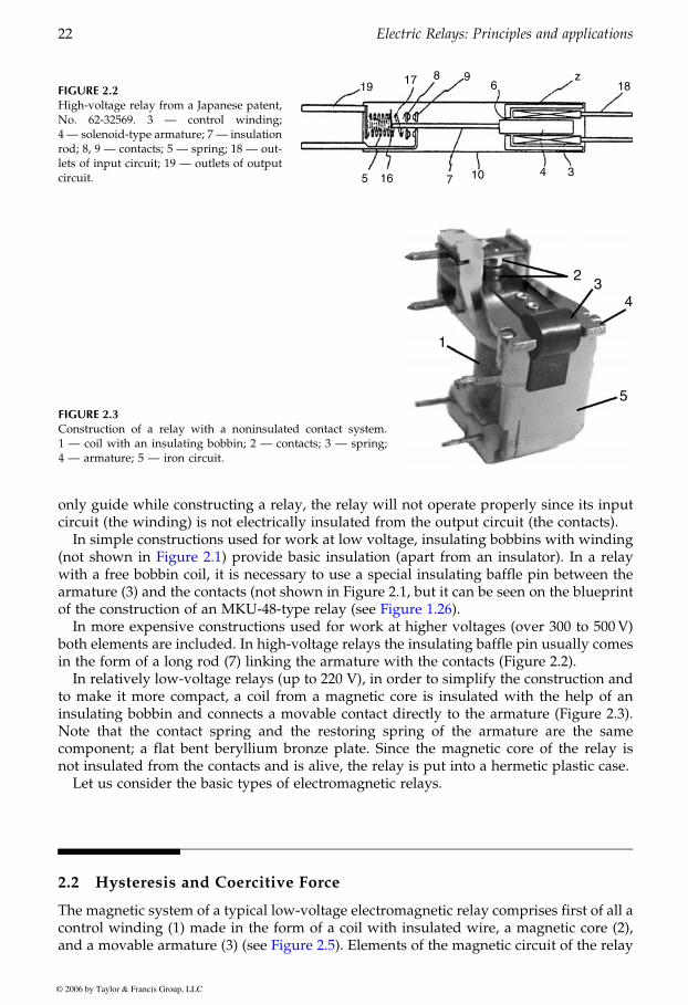
only guide while constructing a relay, the relay will not operate properly since its inputcircuit (the winding) is not electrically insulated from the output circuit (the contacts).
In simple constructions used for work at low voltage, insulating bobbins with winding
with a free bobbin coil, it is necessary to use a special insulating baffle pin between thearmature (3) and the contacts (not shown in Figure 2.1, but it can be seen on the blueprint
In more expensive constructions used for work at higher voltages (over 300 to 500V)both elements are included. In high-voltage relays the insulating baffle pin usually comesin the form of a long rod (7) linking the armature with the contacts (Figure 2.2).
In relatively low-voltage relays (up to 220 V), in order to simplify the construction andto make it more compact, a coil from a magnetic core is insulated with the help of aninsulating bobbin and connects a movable contact directly to the armature (Figure 2.3).Note that the contact spring and the restoring spring of the armature are the samecomponent; a flat bent beryllium bronze plate. Since the magnetic core of the relay isnot insulated from the contacts and is alive, the relay is put into a hermetic plastic case.
Let us consider the basic types of electromagnetic relays.
2.2 Hysteresis and Coercitive Force
The magnetic system of a typical low-voltage electromagnetic relay comprises first of all acontrol winding (1) made in the form of a coil with insulated wire, a magnetic core (2),
FIGURE 2.2High-voltage relay from a Japanese patent,No. 62-32569. 3 — control winding;4 — solenoid-type armature; 7 — insulationrod; 8, 9 — contacts; 5 — spring; 18 — out-lets of input circuit; 19 — outlets of outputcircuit.
FIGURE 2.3Construction of a relay with a noninsulated contact system.1 — coil with an insulating bobbin; 2 — contacts; 3 — spring;4 — armature; 5 — iron circuit.
GUREVICH / Electric Relays: Principles and Practises DK884X_c002 Final Proof page 22 31.10.2005 8:37am
22 Electric Relays: Principles and applications
© 2006 by Taylor & Francis Group, LLC
(not shown in Figure 2.1) provide basic insulation (apart from an insulator). In a relay
of the construction of an MKU-48-type relay (see Figure 1.26).
and a movable armature (3) (see Figure 2.5). Elements of the magnetic circuit of the relay
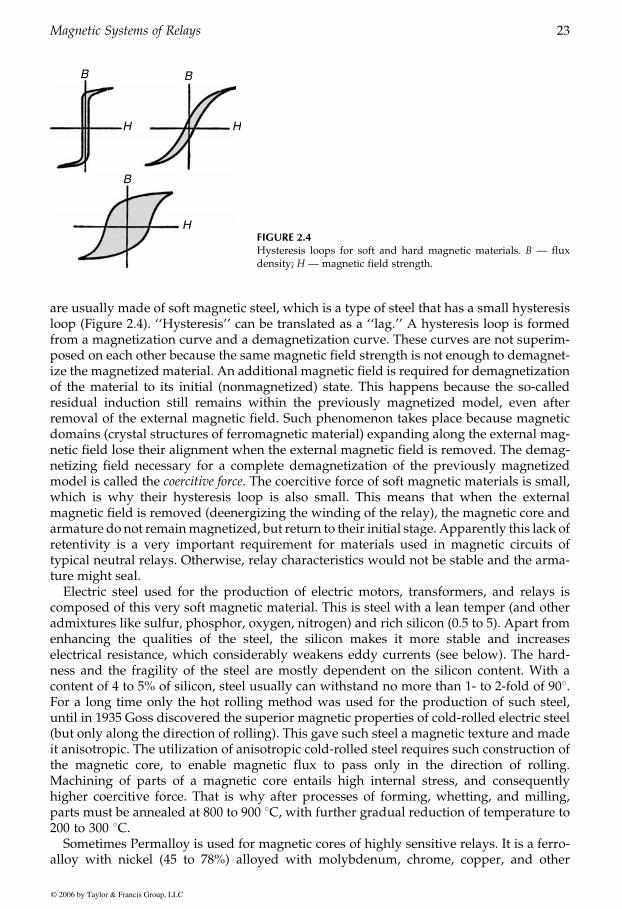
are usually made of soft magnetic steel, which is a type of steel that has a small hysteresisloop (Figure 2.4). ‘‘Hysteresis’’ can be translated as a ‘‘lag.’’ A hysteresis loop is formedfrom a magnetization curve and a demagnetization curve. These curves are not superim-posed on each other because the same magnetic field strength is not enough to demagnet-ize the magnetized material. An additional magnetic field is required for demagnetizationof the material to its initial (nonmagnetized) state. This happens because the so-calledresidual induction still remains within the previously magnetized model, even afterremoval of the external magnetic field. Such phenomenon takes place because magneticdomains (crystal structures of ferromagnetic material) expanding along the external mag-netic field lose their alignment when the external magnetic field is removed. The demag-netizing field necessary for a complete demagnetization of the previously magnetizedmodel is called the coercitive force. The coercitive force of soft magnetic materials is small,which is why their hysteresis loop is also small. This means that when the externalmagnetic field is removed (deenergizing the winding of the relay), the magnetic core andarmature do not remainmagnetized, but return to their initial stage. Apparently this lack ofretentivity is a very important requirement for materials used in magnetic circuits oftypical neutral relays. Otherwise, relay characteristics would not be stable and the arma-ture might seal.
Electric steel used for the production of electric motors, transformers, and relays iscomposed of this very soft magnetic material. This is steel with a lean temper (and otheradmixtures like sulfur, phosphor, oxygen, nitrogen) and rich silicon (0.5 to 5). Apart fromenhancing the qualities of the steel, the silicon makes it more stable and increaseselectrical resistance, which considerably weakens eddy currents (see below). The hard-ness and the fragility of the steel are mostly dependent on the silicon content. With acontent of 4 to 5% of silicon, steel usually can withstand no more than 1- to 2-fold of 908.For a long time only the hot rolling method was used for the production of such steel,until in 1935 Goss discovered the superior magnetic properties of cold-rolled electric steel(but only along the direction of rolling). This gave such steel a magnetic texture and madeit anisotropic. The utilization of anisotropic cold-rolled steel requires such construction ofthe magnetic core, to enable magnetic flux to pass only in the direction of rolling.Machining of parts of a magnetic core entails high internal stress, and consequentlyhigher coercitive force. That is why after processes of forming, whetting, and milling,parts must be annealed at 800 to 900 8C, with further gradual reduction of temperature to200 to 300 8C.
Sometimes Permalloy is used for magnetic cores of highly sensitive relays. It is a ferro-alloy with nickel (45 to 78%) alloyed with molybdenum, chrome, copper, and other
B B
B
H H
HFIGURE 2.4Hysteresis loops for soft and hard magnetic materials. B — fluxdensity; H — magnetic field strength.
GUREVICH / Electric Relays: Principles and Practises DK884X_c002 Final Proof page 23 31.10.2005 8:37am
Magnetic Systems of Relays 23
© 2006 by Taylor & Francis Group, LLC
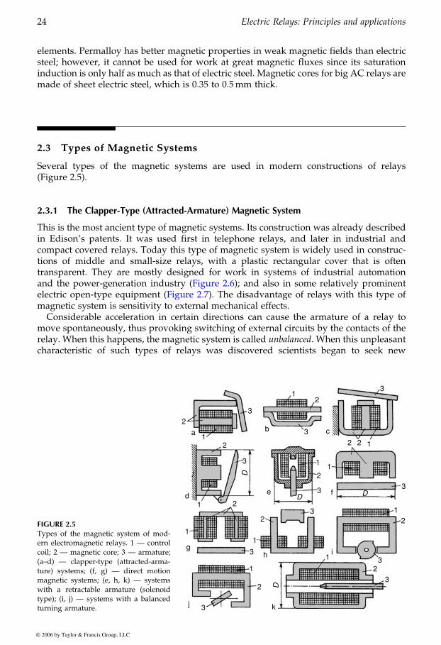
elements. Permalloy has better magnetic properties in weak magnetic fields than electricsteel; however, it cannot be used for work at great magnetic fluxes since its saturationinduction is only half as much as that of electric steel. Magnetic cores for big AC relays aremade of sheet electric steel, which is 0.35 to 0.5mm thick.
2.3 Types of Magnetic Systems
Several types of the magnetic systems are used in modern constructions of relays(Figure 2.5).
2.3.1 The Clapper-Type (Attracted-Armature) Magnetic System
This is the most ancient type of magnetic systems. Its construction was already describedin Edison’s patents. It was used first in telephone relays, and later in industrial andcompact covered relays. Today this type of magnetic system is widely used in construc-tions of middle and small-size relays, with a plastic rectangular cover that is oftentransparent. They are mostly designed for work in systems of industrial automation
magnetic system is sensitivity to external mechanical effects.
move spontaneously, thus provoking switching of external circuits by the contacts of therelay. When this happens, the magnetic system is called unbalanced. When this unpleasantcharacteristic of such types of relays was discovered scientists began to seek new
FIGURE 2.5Types of the magnetic system of mod-ern electromagnetic relays. 1 — controlcoil; 2 — magnetic core; 3 — armature;(a–d) — clapper-type (attracted-arma-ture) systems; (f, g) — direct motionmagnetic systems; (e, h, k) — systemswith a retractable armature (solenoidtype); (i, j) — systems with a balancedturning armature.
2
2
2
2
2
2
2
2
2
2
2
3
3
3
3
3
3
3
3
3
3
31
1
1
1
11
1
1
1
1
1
a b
d
gh
j k
i
e f DD
D
D
c
GUREVICH / Electric Relays: Principles and Practises DK884X_c002 Final Proof page 24 31.10.2005 8:37am
24 Electric Relays: Principles and applications
© 2006 by Taylor & Francis Group, LLC
and the power-generation industry (Figure 2.6); and also in some relatively prominent
Considerable acceleration in certain directions can cause the armature of a relay to
electric open-type equipment (Figure 2.7). The disadvantage of relays with this type of

technological solutions, which would enable the relay to work correctly within transport-able equipment (mostly military equipment).
At first they tried the so-called ‘‘frontal solution’’: if there is some unbalanced weight itshould be balanced, but how? The obvious solution: with the help of an additional weight
FIGURE 2.6Modern attracted-armature relays with a transparent plastic rectangular cover for industrial usages.
FIGURE 2.7Large open relay (of REV-300 type) withclapper-type magnetic system. 1 — U-shaped magnetic core; 2 — flat arma-ture rotating on the prism; 3 — winding(in this instance current windingwound by copper wire); 4 — fasteningpins; 5— spring; 6— screw-nut regulat-ing spring constrictor; 7 — insulatingplate; 8 — movable contact; 9, 10 — sta-tionary contacts; 11 — contact outlet;12 — flexible copper conductor linkingthe contact with the outlet.
GUREVICH / Electric Relays: Principles and Practises DK884X_c002 Final Proof page 25 31.10.2005 8:37am
Magnetic Systems of Relays 25
© 2006 by Taylor & Francis Group, LLC
— a counterweight placed in a certain position (Figure 2.8).
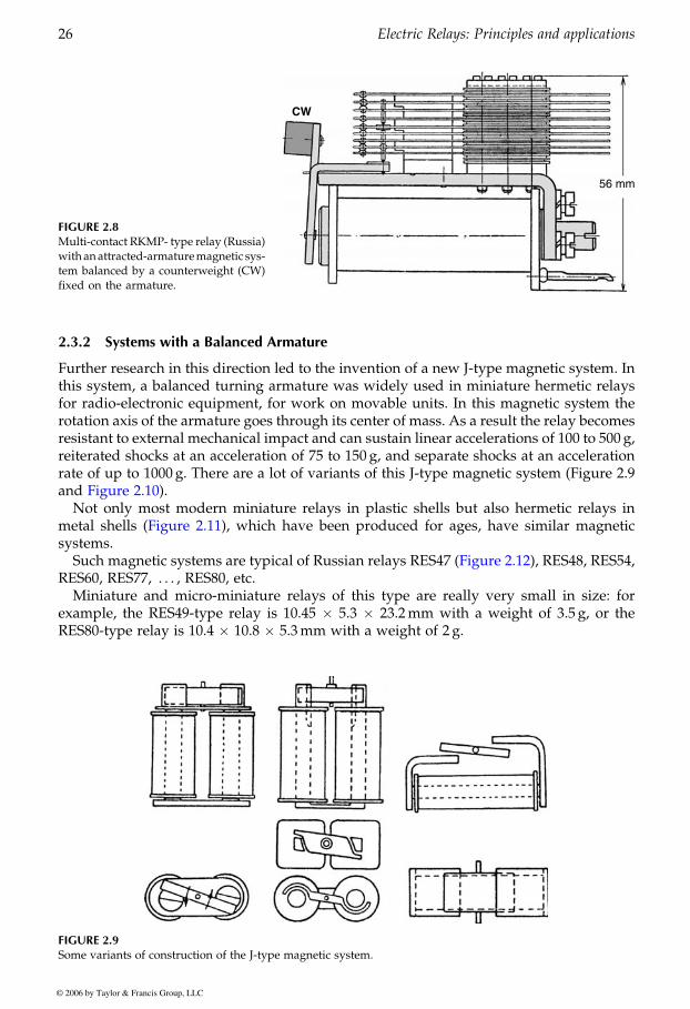
2.3.2 Systems with a Balanced Armature
Further research in this direction led to the invention of a new J-type magnetic system. Inthis system, a balanced turning armature was widely used in miniature hermetic relaysfor radio-electronic equipment, for work on movable units. In this magnetic system therotation axis of the armature goes through its center of mass. As a result the relay becomesresistant to external mechanical impact and can sustain linear accelerations of 100 to 500 g,reiterated shocks at an acceleration of 75 to 150 g, and separate shocks at an accelerationrate of up to 1000 g. There are a lot of variants of this J-type magnetic system (Figure 2.9
Not only most modern miniature relays in plastic shells but also hermetic relays in
systems.
RES60, RES77, . . . , RES80, etc.Miniature and micro-miniature relays of this type are really very small in size: for
example, the RES49-type relay is 10.45 � 5.3 � 23.2mm with a weight of 3.5 g, or theRES80-type relay is 10.4 � 10.8 � 5.3mm with a weight of 2 g.
FIGURE 2.8Multi-contact RKMP- type relay (Russia)withanattracted-armaturemagnetic sys-tem balanced by a counterweight (CW)fixed on the armature.
FIGURE 2.9Some variants of construction of the J-type magnetic system.
GUREVICH / Electric Relays: Principles and Practises DK884X_c002 Final Proof page 26 31.10.2005 8:37am
26 Electric Relays: Principles and applications
© 2006 by Taylor & Francis Group, LLC
and Figure 2.10).
metal shells (Figure 2.11), which have been produced for ages, have similar magnetic
Such magnetic systems are typical of Russian relays RES47 (Figure 2.12), RES48, RES54,
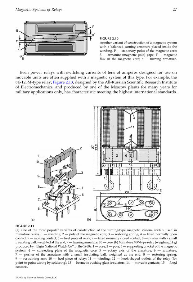
Even power relays with switching currents of tens of amperes designed for use onmovable units are often supplied with a magnetic system of this type. For example, the
of Electromechanics, and produced by one of the Moscow plants for many years formilitary applications only, has characteristic meeting the highest international standards.
F
5
s′
s′
P′
P
E
FIGURE 2.10Another variant of construction of a magnetic systemwith a balanced turning armature placed inside thewinding. P — stationary poles of the magnetic core;S — armature (magnetic pole) gape; F — magneticflux in the magnetic core; 5 — turning armature.
1
10
2
3
4
5
6
7
8
9
(a)
1
2 6 8
15
13
133
15149,
122
,227
10
1220,2
14 9
57
11
4
(b)
FIGURE 2.11(a) One of the most popular variants of construction of the turning-type magnetic system, widely used inminiature relays. 1 — winding; 2 — pole of the magnetic core; 3 — restoring spring; 4 — fixed normally opencontact; 5 —moving contact; 6 — heel piece of relay; 7 — fixed normally closed contact; 8 — pusher with a smallinsulating ball, weighted at the end; 9— turning armature; 10— core. (b)MiniatureMV-type relay (weighing 14 g)produced by ‘‘Elgin National Watch Co’’ in the 1960s. 1— core; 2 — pole; 3 — supporting bracket of the magneticsystem; 4 — connecting plate of the magnetic core; 5 — rotary axis of the armature; 6 — armature;7 — pusher of the armature with a small insulating ball, weighted at the end; 8 — restoring spring;9 — restraining arm; 10 — heel piece of relay; 11 — winding; 12 — hook-shaped outlets of the relay (forpoint-to-point wiring by soldering); 13 — hermetic bushing glass insulators; 14 — movable contacts; 15 — fixedcontacts.
GUREVICH / Electric Relays: Principles and Practises DK884X_c002 Final Proof page 27 31.10.2005 8:37am
Magnetic Systems of Relays 27
© 2006 by Taylor & Francis Group, LLC
8E-123M-type relay, Figure 2.13, designed by the All-Russian Scientific Research Institute
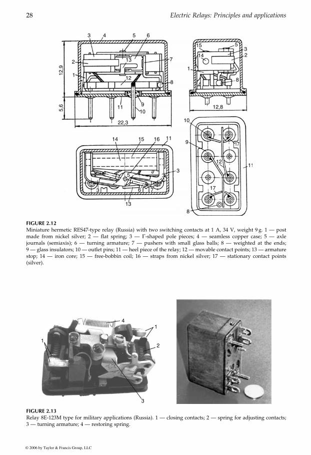
FIGURE 2.12Miniature hermetic RES47-type relay (Russia) with two switching contacts at 1 A, 34 V, weight 9 g. 1 — postmade from nickel silver; 2 — flat spring; 3 — G-shaped pole pieces; 4 — seamless copper case; 5 — axlejournals (semiaxis); 6 — turning armature; 7 — pushers with small glass balls; 8 — weighted at the ends;9 — glass insulators; 10 — outlet pins; 11 — heel piece of the relay; 12 — movable contact points; 13 — armaturestop; 14 — iron core; 15 — free-bobbin coil; 16 — straps from nickel silver; 17 — stationary contact points(silver).
1
1
2
3
4
FIGURE 2.13Relay 8E-123M type for military applications (Russia). 1 — closing contacts; 2 — spring for adjusting contacts;3 — turning armature; 4 — restoring spring.
GUREVICH / Electric Relays: Principles and Practises DK884X_c002 Final Proof page 28 31.10.2005 8:37am
28 Electric Relays: Principles and applications
© 2006 by Taylor & Francis Group, LLC
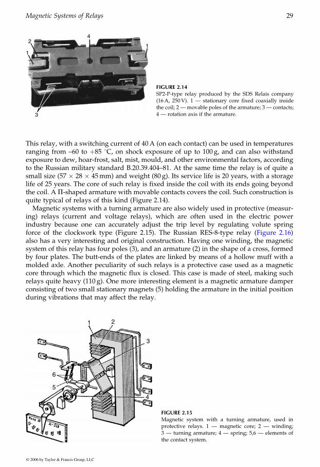
This relay, with a switching current of 40A (on each contact) can be used in temperaturesranging from –60 to þ85 8C, on shock exposure of up to 100 g, and can also withstandexposure to dew, hoar-frost, salt, mist, mould, and other environmental factors, accordingto the Russian military standard B.20.39.404–81. At the same time the relay is of quite asmall size (57 � 28 � 45mm) and weight (80 g). Its service life is 20 years, with a storagelife of 25 years. The core of such relay is fixed inside the coil with its ends going beyondthe coil. A P-shaped armature with movable contacts covers the coil. Such construction isquite typical of relays of this kind (Figure 2.14).
Magnetic systems with a turning armature are also widely used in protective (measur-ing) relays (current and voltage relays), which are often used in the electric powerindustry because one can accurately adjust the trip level by regulating volute spring
also has a very interesting and original construction. Having one winding, the magneticsystem of this relay has four poles (3), and an armature (2) in the shape of a cross, formedby four plates. The butt-ends of the plates are linked by means of a hollow muff with amolded axle. Another peculiarity of such relays is a protective case used as a magneticcore through which the magnetic flux is closed. This case is made of steel, making suchrelays quite heavy (110 g). One more interesting element is a magnetic armature damperconsisting of two small stationary magnets (5) holding the armature in the initial positionduring vibrations that may affect the relay.
FIGURE 2.14SP2-P-type relay produced by the SDS Relais company(16A, 250V). 1 — stationary core fixed coaxially insidethe coil; 2 — movable poles of the armature; 3 — contacts;4 — rotation axis if the armature.
FIGURE 2.15Magnetic system with a turning armature, used inprotective relays. 1 — magnetic core; 2 — winding;3 — turning armature; 4 — spring; 5,6 — elements ofthe contact system.
GUREVICH / Electric Relays: Principles and Practises DK884X_c002 Final Proof page 29 31.10.2005 8:37am
Magnetic Systems of Relays 29
© 2006 by Taylor & Francis Group, LLC
force of the clockwork type (Figure 2.15). The Russian RES-8-type relay (Figure 2.16)
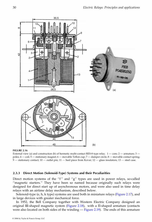
2.3.3 Direct Motion (Solenoid-Type) Systems and their Peculiarities
Direct motion systems of the ‘‘f ’’ and ‘‘g’’ types are used in power relays, so-called‘‘magnetic starters.’’ They have been so named because originally such relays weredesigned for direct start up of asynchronous motors, and were also used in time delayrelays with an airtime delay mechanism, described below.
in large devices with greater mechanical force.In 1952, the Bell Company together with Western Electric Company designed an
with a P-shaped armature (contactsThe ends of this armature
30,5
10 10
12
13
28,5
11842
9
76
3
2
4
5
54
40
49 (b)
13
3
3
3
3
2
2
1
2
(a)
FIGURE 2.16External view (a) and construction (b) of hermetic multi-contact RES-8 type relay. 1 — core; 2 — armature; 3 —poles; 4 — coil; 5 — stationary magnet; 6 —movable Teflon cup; 7 — damper circle; 8 —movable contact spring;9 — stationary contact; 10 — outlet pin; 11 — heel piece from Kovar; 12 — glass insulators; 13 — steel case.
GUREVICH / Electric Relays: Principles and Practises DK884X_c002 Final Proof page 30 31.10.2005 8:37am
30 Electric Relays: Principles and applications
© 2006 by Taylor & Francis Group, LLC
Solenoid-type (e, h, k type) systems are used both in miniature relays (Figure 2.17), and
original I-shaped magnetic system (Figure 2.18),were also located on both sides of the winding — Figure 2.19).

were fixed on the free ends of a P-shaped flat spring. The core of the relay wasI-shaped,its middle rod inside the coil and the outward ones outside of it. When the relay isenergized, the P-shaped core lies level on the outward rods and the end of the internalrod sticks out of the winding, closing the magnetic circuit.
The advantages of this magnetic system are simplicity of production and a very slightmagnetic resistance due to the absence of joints, the wide coupling surfaces of thearmature and the core, which are the poles of this magnetic system. This relay wasquite large, measuring 48.4 � 37.2 � 115mm. (The year 2004 marks 52 years since itwas invented.) It is all the more surprising to come across the descendant of this relay in aprinted circuit card on a modern electric device. This is an A2440-type relay produced by
FIGURE 2.17Miniature Mark-II-type relay produced by ‘‘Electro TechCo.’’ and an exact replica RES-39-type relay (Russia)with a retractable solenoid-type armature. 1 — heelpiece; 2 — core; 3 — steel case; 4 — steel cup; 5 — guidebrass tube; 6 — hollow retractable armature with a glass-shaped conical stopper; 7 — iron body; 8 — nonmagneticbushing; 9 — movable contact springs; 10 — small pin;12 — glass insulator; 13 — stationary contacts;14 — cylindrical spiral spring; 15 — rod; 16 — unionthrough which the relay is filled with dry air and sealed;17 — pusher; 18 — steel posts with the magnetic systemfixed.
GUREVICH / Electric Relays: Principles and Practises DK884X_c002 Final Proof page 31 31.10.2005 8:38am
Magnetic Systems of Relays 31
© 2006 by Taylor & Francis Group, LLC
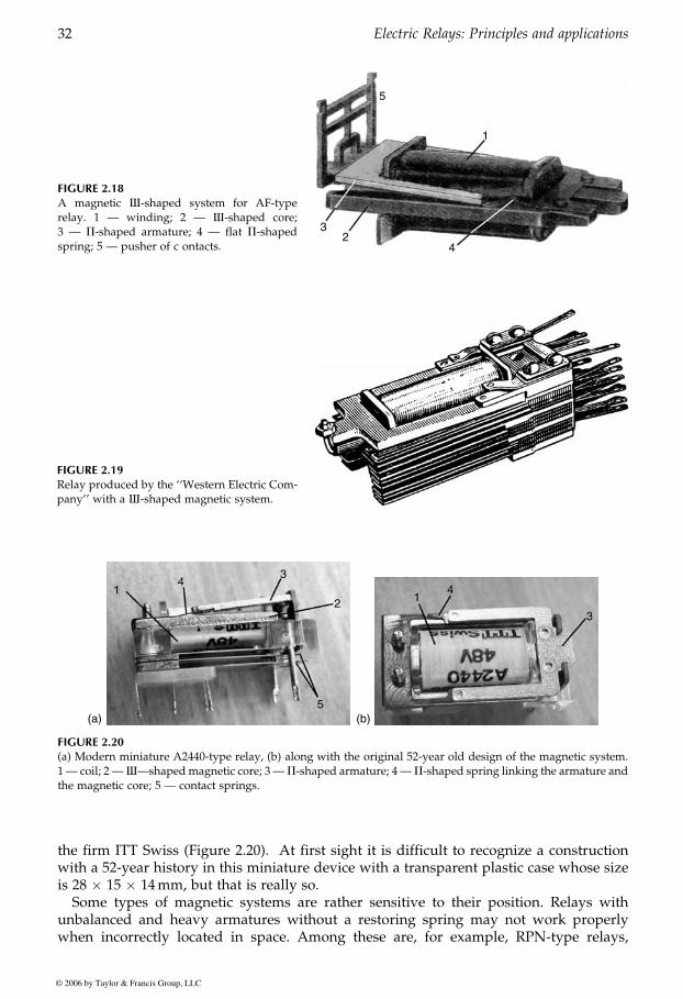
the firm ITT Swiss (Figure 2.20). At first sight it is difficult to recognize a constructionwith a 52-year history in this miniature device with a transparent plastic case whose sizeis 28 � 15 � 14mm, but that is really so.
Some types of magnetic systems are rather sensitive to their position. Relays withunbalanced and heavy armatures without a restoring spring may not work properlywhen incorrectly located in space. Among these are, for example, RPN-type relays,
FIGURE 2.18A magnetic I-shaped system for AF-typerelay. 1 — winding; 2 — I-shaped core;3 — P-shaped armature; 4 — flat P-shapedspring; 5 — pusher of c ontacts.
FIGURE 2.19Relay produced by the ‘‘Western Electric Com-pany’’ with a I-shaped magnetic system.
14
3
2
5(a)
3
14
(b)
FIGURE 2.20(a) Modern miniature A2440-type relay, (b) along with the original 52-year old design of the magnetic system.1 — coil; 2 —I—shapedmagnetic core; 3 —P-shaped armature; 4 —P-shaped spring linking the armature andthe magnetic core; 5 — contact springs.
GUREVICH / Electric Relays: Principles and Practises DK884X_c002 Final Proof page 32 31.10.2005 8:38am
32 Electric Relays: Principles and applications
© 2006 by Taylor & Francis Group, LLC
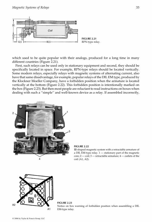
which used to be quite popular with their analogs, produced for a long time in manydifferent countries (Figure 2.21).
First, such relays can be used only in stationary equipment and second, they should bespecifically located in space. For example, RPN-type relays should be located vertically.Some modern relays, especially relays with magnetic systems of alternating current, alsohave that same disadvantage, for example, popular relays of theDIL EM type, produced bythe Klockner Moeller Company, have a forbidden position when the armature is locatedvertically at the bottom (Figure 2.22). This forbidden position is intentionally marked onthe box (Figure 2.23). But thenmost people are reluctant to read instructions on boxeswhendealing with such a ‘‘simple’’ and well-known device as a relay. If assembled incorrectly,
FIGURE 2.21RPN-type relay.
2 1
3
4
FIGURE 2.22I-shapedmagnetic systemwith a retractable armature ofa DIL EM-type relay. 1 — stationary part of the magneticcore; 2 — coil; 3 — retractable armature; 4 — outlets of thecoil (A1, A2).
A2
A1
FIGURE 2.23Notice on box warning of forbidden position when assembling a DILEM-type relay.
GUREVICH / Electric Relays: Principles and Practises DK884X_c002 Final Proof page 33 31.10.2005 8:38am
Magnetic Systems of Relays 33
© 2006 by Taylor & Francis Group, LLC
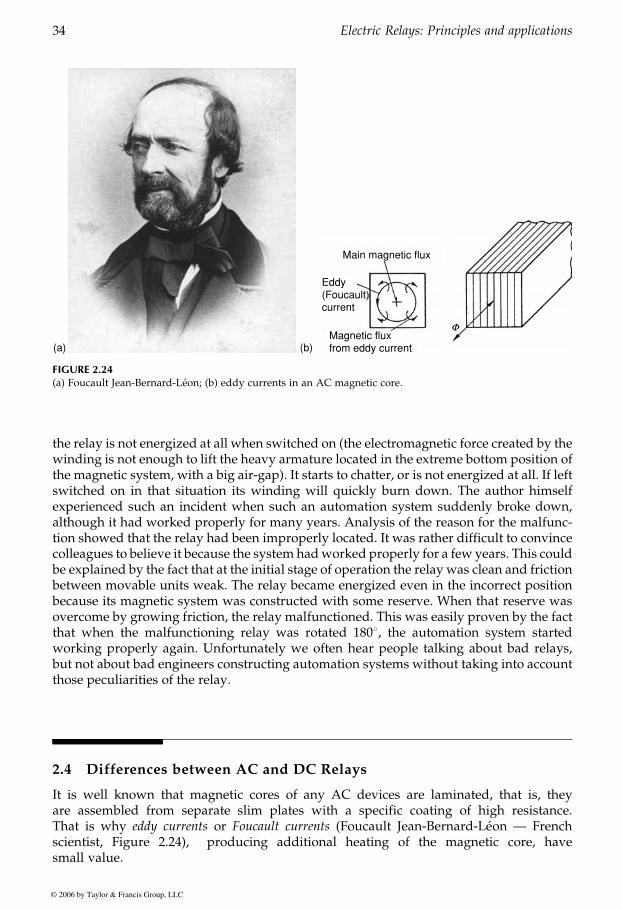
the relay is not energized at all when switched on (the electromagnetic force created by thewinding is not enough to lift the heavy armature located in the extreme bottom position ofthe magnetic system, with a big air-gap). It starts to chatter, or is not energized at all. If leftswitched on in that situation its winding will quickly burn down. The author himselfexperienced such an incident when such an automation system suddenly broke down,although it had worked properly for many years. Analysis of the reason for the malfunc-tion showed that the relay had been improperly located. It was rather difficult to convincecolleagues to believe it because the system hadworked properly for a few years. This couldbe explained by the fact that at the initial stage of operation the relay was clean and frictionbetween movable units weak. The relay became energized even in the incorrect positionbecause its magnetic system was constructed with some reserve. When that reserve wasovercome by growing friction, the relay malfunctioned. This was easily proven by the factthat when the malfunctioning relay was rotated 1808, the automation system startedworking properly again. Unfortunately we often hear people talking about bad relays,but not about bad engineers constructing automation systems without taking into accountthose peculiarities of the relay.
2.4 Differences between AC and DC Relays
It is well known that magnetic cores of any AC devices are laminated, that is, theyare assembled from separate slim plates with a specific coating of high resistance.That is why eddy currents or Foucault currents (Foucault Jean-Bernard-Leon — Frenchscientist, Figure 2.24), producing additional heating of the magnetic core, havesmall value.
(a) (b)
Main magnetic flux
Eddy(Foucault)current
Magnetic fluxfrom eddy current
F
FIGURE 2.24(a) Foucault Jean-Bernard-Leon; (b) eddy currents in an AC magnetic core.
GUREVICH / Electric Relays: Principles and Practises DK884X_c002 Final Proof page 34 31.10.2005 8:38am
34 Electric Relays: Principles and applications
© 2006 by Taylor & Francis Group, LLC
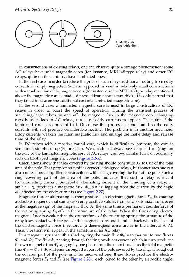
In constructions of existing relays, one can observe quite a strange phenomenon: someAC relays have solid magnetic cores (for instance, MKU-48-type relay) and other DCrelays, quite on the contrary, have laminated ones.
In the first case, in order to reduce the price of such relays additional heating from eddycurrents is simply neglected. Such an approach is used in relatively small constructionswith a small section of themagnetic core (for instance, in theMKU-48-type relaymentionedabove the magnetic core is made of pressed iron about 4mm thick. It is only natural thatthey failed to take on the additional cost of a laminated magnetic core).
In the second case, a laminated magnetic core is used in large constructions of DCrelays in order to boost the speed of operation. During the transient process ofswitching large relays on and off, the magnetic flux in the magnetic core, changingrapidly as it does in AC relays, can cause eddy currents to appear. The point of thelaminated core is to prevent that. Of course this process is time-bound so the eddycurrents will not produce considerable heating. The problem is in another area here.Eddy currents weaken the main magnetic flux and enlarge the make delay and releasetime of the relay.
In DC relays with a massive round core, which is difficult to laminate, the core issometimes simply cut up (Figure 2.25). We can almost always see a copper turn (ring) onthe pole of the laminated magnetic core of AC relays, and two similar turns on boundary
Calculations show that area covered by the ring should constitute 0.7 to 0.85 of the totalarea of the pole. That proportion typifies correctly designed relays, but sometimes one canalso come across simplified constructions with a ring covering the half of the pole. Such aring, covering part of the area of the pole, indicates that such a relay is meantfor alternating current. Sinusoidal alternating current in the winding of a relay, Imsin(vt þ t), produces a magnetic flux, Fm sin vt, lagging from the current by the anglewm
Magnetic flux of alternating current produces an electromagnetic force Fm fluctuatingat double frequency that can take on only positive values, from zero to its maximum, evenat the negative sign of the magnetic flux. At the same time a permanent counterforce ofthe restoring spring FS affects the armature of the relay. When the fluctuating electro-magnetic force is weaker than the counterforce of the restoring spring, the armature of therelay loses contact with the pole of the magnetic core, and is pulled back when the level ofthe electromagnetic force is restored (a deenergized armature is in the interval A–A).Thus, vibration will appear in the armature of an AC relay.
In a magnetic system with a shading ring the main flux F0 branches out to two fluxesF1 and F2. The flux F2 passing through the ring produces current which in turn producesits ownmagnetic fluxFr lagging by one phase from the main flux. Thus the total magneticfluxFS ¼ F2 þFr will pass through that part of the pole covered by the ring. Throughoutthe covered part of the pole, and the uncovered one, these fluxes produce the electro-magnetic forces F1 and F2 each joined to the other by a specific angle.
FIGURE 2.25Core with slits.
GUREVICH / Electric Relays: Principles and Practises DK884X_c002 Final Proof page 35 31.10.2005 8:38am
Magnetic Systems of Relays 35
© 2006 by Taylor & Francis Group, LLC
rods on I-shaped magnetic cores (Figure 2.26c).
affected by the eddy currents (see Figure 2.27).
(see Figure 2.28),
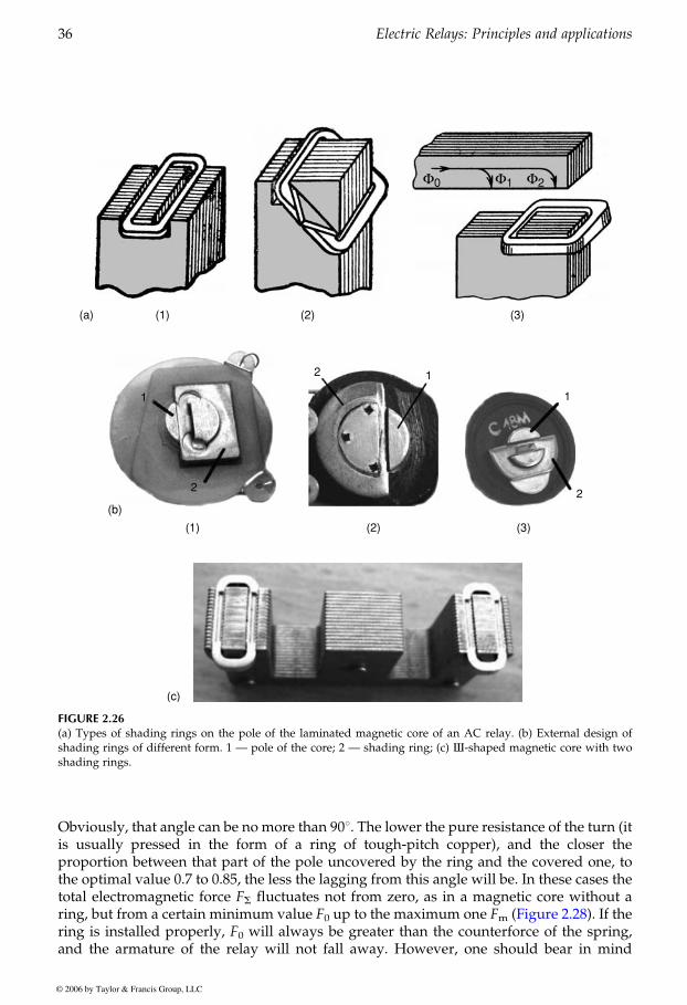
Obviously, that angle can be no more than 908. The lower the pure resistance of the turn (itis usually pressed in the form of a ring of tough-pitch copper), and the closer theproportion between that part of the pole uncovered by the ring and the covered one, tothe optimal value 0.7 to 0.85, the less the lagging from this angle will be. In these cases thetotal electromagnetic force FS fluctuates not from zero, as in a magnetic core without aring, but from a certain minimum value F0 up to the maximum one Fmring is installed properly, F0 will always be greater than the counterforce of the spring,and the armature of the relay will not fall away. However, one should bear in mind
(1) (2) (3)
Φ0 Φ1 Φ2
(a)
2 1
2
11
2
(b)
(1) (2) (3)
(c)
FIGURE 2.26(a) Types of shading rings on the pole of the laminated magnetic core of an AC relay. (b) External design ofshading rings of different form. 1 — pole of the core; 2 — shading ring; (c) I-shaped magnetic core with twoshading rings.
GUREVICH / Electric Relays: Principles and Practises DK884X_c002 Final Proof page 36 31.10.2005 8:38am
36 Electric Relays: Principles and applications
© 2006 by Taylor & Francis Group, LLC
(Figure 2.28). If the
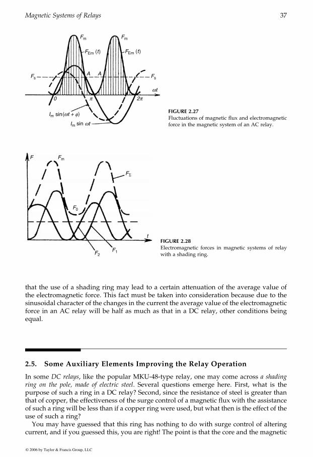
that the use of a shading ring may lead to a certain attenuation of the average value ofthe electromagnetic force. This fact must be taken into consideration because due to thesinusoidal character of the changes in the current the average value of the electromagneticforce in an AC relay will be half as much as that in a DC relay, other conditions beingequal.
2.5. Some Auxiliary Elements Improving the Relay Operation
In some DC relays, like the popular MKU-48-type relay, one may come across a shadingring on the pole, made of electric steel. Several questions emerge here. First, what is thepurpose of such a ring in a DC relay? Second, since the resistance of steel is greater thanthat of copper, the effectiveness of the surge control of a magnetic flux with the assistanceof such a ring will be less than if a copper ring were used, but what then is the effect of theuse of such a ring?
You may have guessed that this ring has nothing to do with surge control of alteringcurrent, and if you guessed this, you are right! The point is that the core and the magnetic
f
Fm Fm
FEm (t) FEm (t)
Fs Fs
m
m ( ) FIGURE 2.27Fluctuations of magnetic flux and electromagneticforce in the magnetic system of an AC relay.
m
Σ
0
21
FIGURE 2.28Electromagnetic forces in magnetic systems of relaywith a shading ring.
GUREVICH / Electric Relays: Principles and Practises DK884X_c002 Final Proof page 37 31.10.2005 8:38am
Magnetic Systems of Relays 37
© 2006 by Taylor & Francis Group, LLC
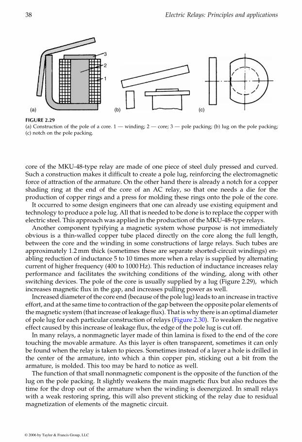
core of the MKU-48-type relay are made of one piece of steel duly pressed and curved.Such a construction makes it difficult to create a pole lug, reinforcing the electromagneticforce of attraction of the armature. On the other hand there is already a notch for a coppershading ring at the end of the core of an AC relay, so that one needs a die for theproduction of copper rings and a press for molding these rings onto the pole of the core.
It occurred to some design engineers that one can already use existing equipment andtechnology to produce a pole lug. All that is needed to be done is to replace the copper withelectric steel. This approach was applied in the production of theMKU-48-type relays.
Another component typifying a magnetic system whose purpose is not immediatelyobvious is a thin-walled copper tube placed directly on the core along the full length,between the core and the winding in some constructions of large relays. Such tubes areapproximately 1.2mm thick (sometimes these are separate shorted-circuit windings) en-abling reduction of inductance 5 to 10 times more when a relay is supplied by alternatingcurrent of higher frequency (400 to 1000Hz). This reduction of inductance increases relayperformance and facilitates the switching conditions of the winding, along with otherswitching devices. The pole of the core is usually supplied by a lug (Figure 2.29), whichincreases magnetic flux in the gap, and increases pulling power as well.
Increaseddiameter of the core end (because of the pole lug) leads to an increase in tractiveeffort, and at the same time to contraction of the gap between the opposite polar elements ofthemagnetic system (that increase of leakage flux). That iswhy there is an optimal diameter
effect caused by this increase of leakage flux, the edge of the pole lug is cut off.In many relays, a nonmagnetic layer made of thin lamina is fixed to the end of the core
touching the movable armature. As this layer is often transparent, sometimes it can onlybe found when the relay is taken to pieces. Sometimes instead of a layer a hole is drilled inthe center of the armature, into which a thin copper pin, sticking out a bit from thearmature, is molded. This too may be hard to notice as well.
The function of that small nonmagnetic component is the opposite of the function of thelug on the pole packing. It slightly weakens the main magnetic flux but also reduces thetime for the drop out of the armature when the winding is deenergized. In small relayswith a weak restoring spring, this will also prevent sticking of the relay due to residualmagnetization of elements of the magnetic circuit.
3
2
1
(a) (b) (c)
FIGURE 2.29(a) Construction of the pole of a core. 1 — winding; 2 — core; 3 — pole packing; (b) lug on the pole packing;(c) notch on the pole packing.
GUREVICH / Electric Relays: Principles and Practises DK884X_c002 Final Proof page 38 31.10.2005 8:38am
38 Electric Relays: Principles and applications
© 2006 by Taylor & Francis Group, LLC
of pole lug for each particular construction of relays (Figure 2.30). To weaken the negative
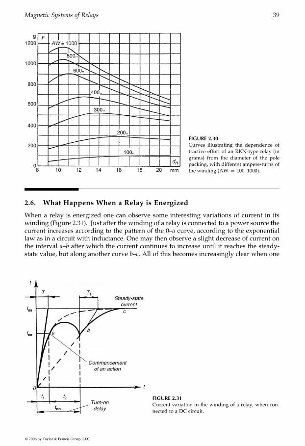
2.6. What Happens When a Relay is Energized
When a relay is energized one can observe some interesting variations of current in itswinding (Figure 2.31). Just after the winding of a relay is connected to a power source thecurrent increases according to the pattern of the 0–a curve, according to the exponentiallaw as in a circuit with inductance. One may then observe a slight decrease of current onthe interval a–b after which the current continues to increase until it reaches the steady-state value, but along another curve b–c. All of this becomes increasingly clear when one
g1200
FAW = 1000
800’’
600’’
400’’
300’’
200’’
100’’dn
1000
800
600
400
200
08 10 12 14 16 18 20 mm
FIGURE 2.30Curves illustrating the dependence oftractive effort of an RKN-type relay (ingrams) from the diameter of the polepacking, with different ampere-turns ofthe winding (AW ¼ 100–1000).
I
0
a b
c
Steady-statecurrent
Commencementof an action
Turn-ondelay
T1
t1 t2
t
T
Iss
ton
Ica
FIGURE 2.31Current variation in the winding of a relay, when con-nected to a DC circuit.
GUREVICH / Electric Relays: Principles and Practises DK884X_c002 Final Proof page 39 31.10.2005 8:38am
Magnetic Systems of Relays 39
© 2006 by Taylor & Francis Group, LLC
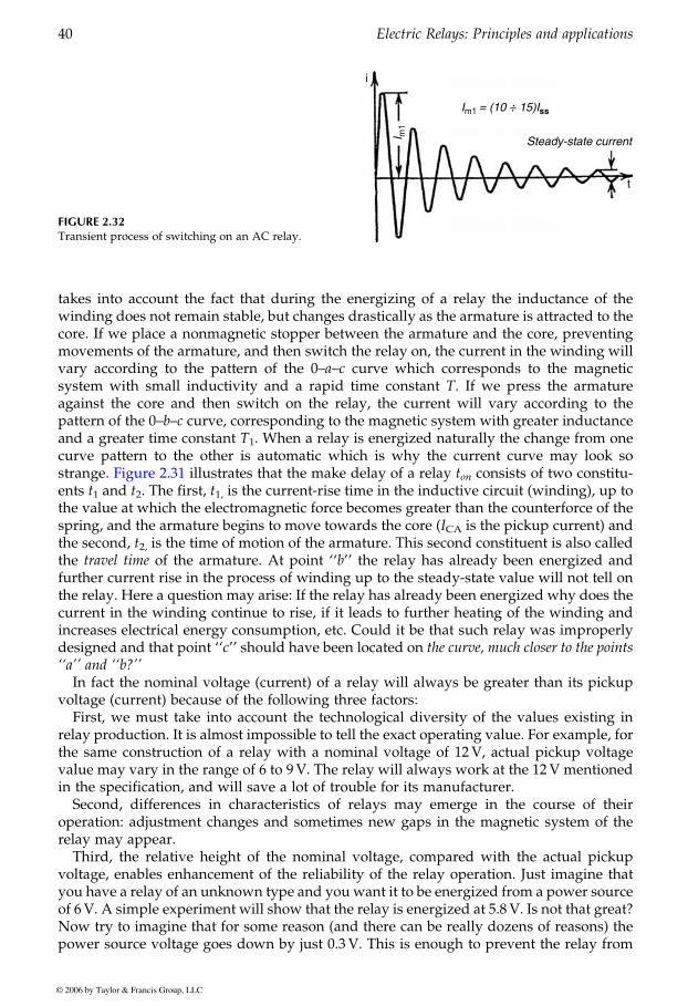
takes into account the fact that during the energizing of a relay the inductance of thewinding does not remain stable, but changes drastically as the armature is attracted to thecore. If we place a nonmagnetic stopper between the armature and the core, preventingmovements of the armature, and then switch the relay on, the current in the winding willvary according to the pattern of the 0–a–c curve which corresponds to the magneticsystem with small inductivity and a rapid time constant T. If we press the armatureagainst the core and then switch on the relay, the current will vary according to thepattern of the 0–b–c curve, corresponding to the magnetic system with greater inductanceand a greater time constant T1. When a relay is energized naturally the change from onecurve pattern to the other is automatic which is why the current curve may look so
on consists of two constitu-ents t1 and t2. The first, t1, is the current-rise time in the inductive circuit (winding), up tothe value at which the electromagnetic force becomes greater than the counterforce of thespring, and the armature begins to move towards the core (ICA is the pickup current) andthe second, t2, is the time of motion of the armature. This second constituent is also calledthe travel time of the armature. At point ‘‘b’’ the relay has already been energized andfurther current rise in the process of winding up to the steady-state value will not tell onthe relay. Here a question may arise: If the relay has already been energized why does thecurrent in the winding continue to rise, if it leads to further heating of the winding andincreases electrical energy consumption, etc. Could it be that such relay was improperlydesigned and that point ‘‘c’’ should have been located on the curve, much closer to the points‘‘a’’ and ‘‘b?’’
In fact the nominal voltage (current) of a relay will always be greater than its pickupvoltage (current) because of the following three factors:
First, we must take into account the technological diversity of the values existing inrelay production. It is almost impossible to tell the exact operating value. For example, forthe same construction of a relay with a nominal voltage of 12V, actual pickup voltagevalue may vary in the range of 6 to 9V. The relay will always work at the 12V mentionedin the specification, and will save a lot of trouble for its manufacturer.
Second, differences in characteristics of relays may emerge in the course of theiroperation: adjustment changes and sometimes new gaps in the magnetic system of therelay may appear.
Third, the relative height of the nominal voltage, compared with the actual pickupvoltage, enables enhancement of the reliability of the relay operation. Just imagine thatyou have a relay of an unknown type and you want it to be energized from a power sourceof 6V. A simple experiment will show that the relay is energized at 5.8 V. Is not that great?Now try to imagine that for some reason (and there can be really dozens of reasons) thepower source voltage goes down by just 0.3 V. This is enough to prevent the relay from
FIGURE 2.32Transient process of switching on an AC relay.
i
t
I m1
Im1 = (10 ÷ 15)Iss
Steady-state current
GUREVICH / Electric Relays: Principles and Practises DK884X_c002 Final Proof page 40 31.10.2005 8:38am
40 Electric Relays: Principles and applications
© 2006 by Taylor & Francis Group, LLC
strange. Figure 2.31 illustrates that the make delay of a relay t
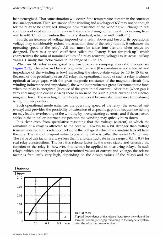
being energized. That same situation will occur if the temperature goes up in the course ofits usual operation. Then, resistance of the winding and a voltage of 6Vmay not be enoughfor the relay to be energized. Imagine how resistance of the winding will change in realconditions of exploitation of a relay in the standard range of temperatures varying from�20 to þ40 8C (not to mention the military standard, which is �60 to þ85 8C).
Fourth, an increase of voltage imposed on a relay above and beyond its operationalvoltage may considerably reduce the actuation time of the relay (that is, it enhances theoperating speed of the relay). All this must be taken into account when relays aredesigned. There is a special coefficient called the ‘‘safety factor for pick-up’’ whichcharacterizes the ratio of nominal values of a relay (current, voltage) to its actual pickupvalues. Usually this factor varies in the range of 1.2 to 1.8.
When an AC relay is energized one can observe a damping aperiodic process (seecharacterized by a strong initial current (the armature is not attracted and
impedance of the winding is low) exceeding the steady-state value by 10 to 15 times.Because of this peculiarity of an AC relay, the operational mode of such a relay is almostoptimal: at large gaps, with the great magnetic resistance of the magnetic circuit (lowwinding inductance and impedance), the winding produces a great electromagnetic forcewhen the relay is energized (because of the great initial current). After that (when gap iszero and magnetic circuit closed) there is no need for such a great current and electro-magnetic force. The winding automatically reduces it because its inductance (impedance)is high in this position.
Such operational mode enhances the operating speed of the relay (the so-called self-forcing) and provides the possibility of extension of a specific gap, but frequent switchingon may lead to overheating of the winding by strong starting currents, and if the armaturesticks in the initial or intermediate position the winding may quickly burn down.
It is clear even from speculative reasoning that the voltage (current) at which thearmature of a relay is attracted to the core will always be a bit stronger than voltage(current) needed for its retention, let alone the voltage at which the armature falls off fromthe core. The ratio of dropout value to operating value is called the release factor of relay.The value of this factor is always less than 1 and can fluctuate in the range of 0.1 to 0.99 forreal relay constructions. The less this release factor is, the more stable and effective thefunction of the relay is; however, this cannot be applied to measuring relays. In suchrelays, which are energized at predetermined values of current and voltage, the releasefactor is frequently very high, depending on the design values of the relays and the
0.10
Urelease
Unom
0.08
0.06
0.04
0.02
00.1 0.2 0.3
δ
mm
FIGURE 2.33Typical dependence of the release factor from the value of theterminal nonmagnetic gap remaining in the magnetic system,after the relay has been energized.
GUREVICH / Electric Relays: Principles and Practises DK884X_c002 Final Proof page 41 31.10.2005 8:38am
Magnetic Systems of Relays 41
© 2006 by Taylor & Francis Group, LLC
Figure 2.32),
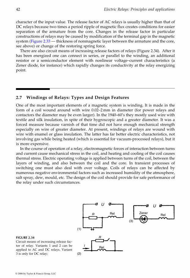
character of the input value. The release factor of AC relays is usually higher than that ofDC relays because two times a period ripple of magnetic flux creates conditions for easierseparation of the armature from the core. Changes in the release factor in particularconstructions of relays may be caused by modification of the terminal gap in the magnetic
see above) or change of the restoring spring force.There are also circuit means of increasing release factors of relays (Figure 2.34). After it
has been energized one can connect in series, or parallel to the winding, an additionalresistor or a semiconductor element with nonlinear voltage–current characteristics (aZener diode, for instance) which rapidly changes its conductivity at the relay energizingpoint.
2.7 Windings of Relays: Types and Design Features
One of the most important elements of a magnetic system is winding. It is made in theform of a coil wound around with wire 0.02–2mm in diameter (for power relays andcontactors the diameter may be even larger). In the 1940–60’s they mostly used wire withtextile and silk insulation, in spite of their hygroscopic and a greater diameter. It was aforced measure because varnish of that time did not have enough mechanical strengthespecially on wire of greater diameter. At present, windings of relays are wound withwire with enamel or glass insulation. The latter has far better electric characteristics, notinvolving gas while being heated (which is essential for vacuum-processed relays), but itis more expensive.
In the course of operation of a relay, electromagnetic forces of interaction between turnsand current cause mechanical stress in the coil, and heating and cooling of the coil causesthermal stress. Electric operating voltage is applied between turns of the coil, between thelayers of winding, and also between the coil and the core. In transient processes ofswitching one must also deal with over voltage. Coils of relays can be affected bynumerous negative environmental factors such as increased humidity of the atmosphere,salt spray, dew, mould, etc. The design of the coil should provide for safe performance ofthe relay under such circumstances.
FIGURE 2.34Circuit means of increasing release fac-tor of relay. Variants 1 and 2 can beapplied to AC and DC relays. Variant3 is only for DC relay;
R Rel
Rel
RelZener
R
I
U U
(1)
(2)
(3)
GUREVICH / Electric Relays: Principles and Practises DK884X_c002 Final Proof page 42 31.10.2005 8:38am
42 Electric Relays: Principles and applications
© 2006 by Taylor & Francis Group, LLC
system (Figure 2.33 — thickness of nonmagnetic layer between the armature and the core,
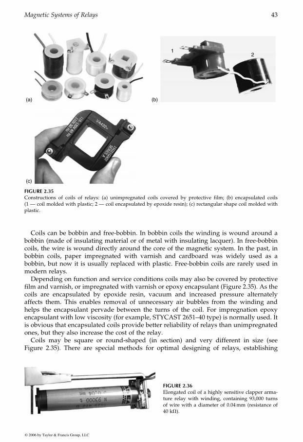
Coils can be bobbin and free-bobbin. In bobbin coils the winding is wound around abobbin (made of insulating material or of metal with insulating lacquer). In free-bobbincoils, the wire is wound directly around the core of the magnetic system. In the past, inbobbin coils, paper impregnated with varnish and cardboard was widely used as abobbin, but now it is usually replaced with plastic. Free-bobbin coils are rarely used inmodern relays.
Depending on function and service conditions coils may also be covered by protectivefilm and varnish, or impregnated with varnish or epoxy encapsulant (Figure 2.35). As thecoils are encapsulated by epoxide resin, vacuum and increased pressure alternatelyaffects them. This enables removal of unnecessary air bubbles from the winding andhelps the encapsulant pervade between the turns of the coil. For impregnation epoxyencapsulant with low viscosity (for example, STYCAST 2651–40 type) is normally used. Itis obvious that encapsulated coils provide better reliability of relays than unimpregnatedones, but they also increase the cost of the relay.
Coils may be square or round-shaped (in section) and very different in size (seeFigure 2.35). There are special methods for optimal designing of relays, establishing
(a)
12
(b)
(c)
FIGURE 2.35Constructions of coils of relays: (a) unimpregnated coils covered by protective film; (b) encapsulated coils(1 — coil molded with plastic; 2 — coil encapsulated by epoxide resin); (c) rectangular shape coil molded withplastic.
FIGURE 2.36Elongated coil of a highly sensitive clapper arma-ture relay with winding, containing 93,000 turnsof wire with a diameter of 0.04mm (resistance of40 kV).
GUREVICH / Electric Relays: Principles and Practises DK884X_c002 Final Proof page 43 31.10.2005 8:38am
Magnetic Systems of Relays 43
© 2006 by Taylor & Francis Group, LLC
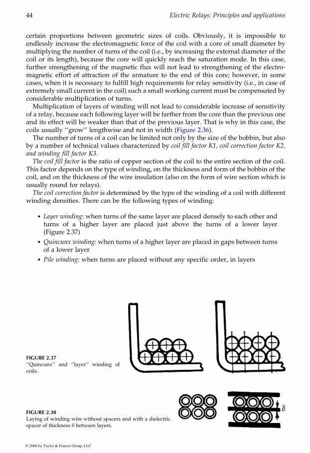
certain proportions between geometric sizes of coils. Obviously, it is impossible toendlessly increase the electromagnetic force of the coil with a core of small diameter bymultiplying the number of turns of the coil (i.e., by increasing the external diameter of thecoil or its length), because the core will quickly reach the saturation mode. In this case,further strengthening of the magnetic flux will not lead to strengthening of the electro-magnetic effort of attraction of the armature to the end of this core; however, in somecases, when it is necessary to fulfill high requirements for relay sensitivity (i.e., in case ofextremely small current in the coil) such a small working current must be compensated byconsiderable multiplication of turns.
Multiplication of layers of winding will not lead to considerable increase of sensitivityof a relay, because each following layer will be farther from the core than the previous oneand its effect will be weaker than that of the previous layer. That is why in this case, the
The number of turns of a coil can be limited not only by the size of the bobbin, but alsoby a number of technical values characterized by coil fill factor K1, coil correction factor K2,and winding fill factor K3.
The coil fill factor is the ratio of copper section of the coil to the entire section of the coil.This factor depends on the type of winding, on the thickness and form of the bobbin of thecoil, and on the thickness of the wire insulation (also on the form of wire section which isusually round for relays).
The coil correction factor is determined by the type of the winding of a coil with differentwinding densities. There can be the following types of winding:
. Layer winding: when turns of the same layer are placed densely to each other andturns of a higher layer are placed just above the turns of a lower layer(Figure 2.37)
. Quincunx winding: when turns of a higher layer are placed in gaps between turnsof a lower layer
. Pile winding: when turns are placed without any specific order, in layers
FIGURE 2.37‘‘Quincunx’’ and ‘‘layer’’ winding ofcoils.
FIGURE 2.38Laying of winding wire without spacers and with a dielectricspacer of thickness d between layers.
GUREVICH / Electric Relays: Principles and Practises DK884X_c002 Final Proof page 44 31.10.2005 8:38am
44 Electric Relays: Principles and applications
© 2006 by Taylor & Francis Group, LLC
coils usually ‘‘grow’’ lengthwise and not in width (Figure 2.36).
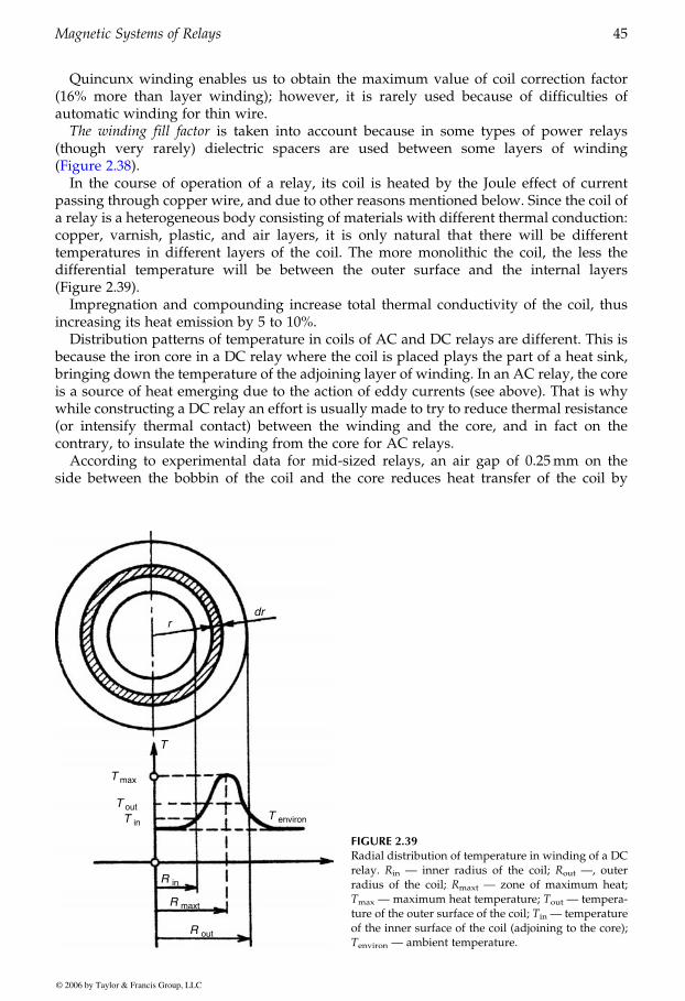
Quincunx winding enables us to obtain the maximum value of coil correction factor(16% more than layer winding); however, it is rarely used because of difficulties ofautomatic winding for thin wire.
The winding fill factor is taken into account because in some types of power relays(though very rarely) dielectric spacers are used between some layers of winding
In the course of operation of a relay, its coil is heated by the Joule effect of currentpassing through copper wire, and due to other reasons mentioned below. Since the coil ofa relay is a heterogeneous body consisting of materials with different thermal conduction:copper, varnish, plastic, and air layers, it is only natural that there will be differenttemperatures in different layers of the coil. The more monolithic the coil, the less thedifferential temperature will be between the outer surface and the internal layers(Figure 2.39).
Impregnation and compounding increase total thermal conductivity of the coil, thusincreasing its heat emission by 5 to 10%.
Distribution patterns of temperature in coils of AC and DC relays are different. This isbecause the iron core in a DC relay where the coil is placed plays the part of a heat sink,bringing down the temperature of the adjoining layer of winding. In an AC relay, the coreis a source of heat emerging due to the action of eddy currents (see above). That is whywhile constructing a DC relay an effort is usually made to try to reduce thermal resistance(or intensify thermal contact) between the winding and the core, and in fact on thecontrary, to insulate the winding from the core for AC relays.
According to experimental data for mid-sized relays, an air gap of 0.25mm on theside between the bobbin of the coil and the core reduces heat transfer of the coil by
rdr
T
T max
T outT in
R maxt
R out
R in
T environ
FIGURE 2.39Radial distribution of temperature in winding of a DCrelay. Rin — inner radius of the coil; Rout —, outerradius of the coil; Rmaxt — zone of maximum heat;Tmax — maximum heat temperature; Tout — tempera-ture of the outer surface of the coil; Tin — temperatureof the inner surface of the coil (adjoining to the core);Tenviron — ambient temperature.
GUREVICH / Electric Relays: Principles and Practises DK884X_c002 Final Proof page 45 31.10.2005 8:38am
Magnetic Systems of Relays 45
© 2006 by Taylor & Francis Group, LLC
(Figure 2.38).
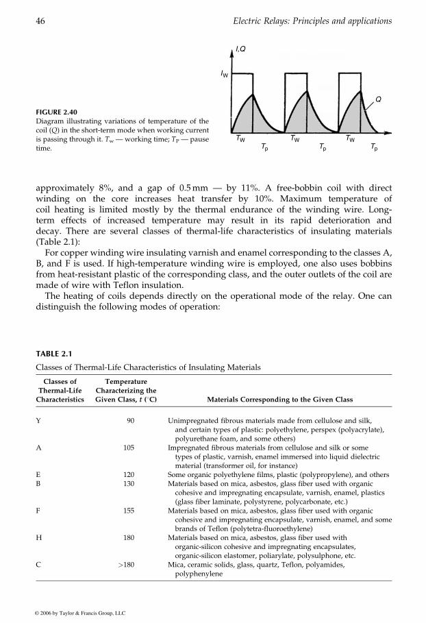
approximately 8%, and a gap of 0.5mm — by 11%. A free-bobbin coil with directwinding on the core increases heat transfer by 10%. Maximum temperature ofcoil heating is limited mostly by the thermal endurance of the winding wire. Long-term effects of increased temperature may result in its rapid deterioration anddecay. There are several classes of thermal-life characteristics of insulating materials(Table 2.1):
For copper winding wire insulating varnish and enamel corresponding to the classes A,B, and F is used. If high-temperature winding wire is employed, one also uses bobbinsfrom heat-resistant plastic of the corresponding class, and the outer outlets of the coil aremade of wire with Teflon insulation.
The heating of coils depends directly on the operational mode of the relay. One candistinguish the following modes of operation:
TABLE 2.1
Classes of Thermal-Life Characteristics of Insulating Materials
Classes of
Thermal-Life
Characteristics
Temperature
Characterizing the
Given Class, t (8C) Materials Corresponding to the Given Class
Y 90 Unimpregnated fibrous materials made from cellulose and silk,and certain types of plastic: polyethylene, perspex (polyacrylate),polyurethane foam, and some others)
A 105 Impregnated fibrous materials from cellulose and silk or sometypes of plastic, varnish, enamel immersed into liquid dielectricmaterial (transformer oil, for instance)
E 120 Some organic polyethylene films, plastic (polypropylene), and othersB 130 Materials based on mica, asbestos, glass fiber used with organic
cohesive and impregnating encapsulate, varnish, enamel, plastics(glass fiber laminate, polystyrene, polycarbonate, etc.)
F 155 Materials based on mica, asbestos, glass fiber used with organiccohesive and impregnating encapsulate, varnish, enamel, and somebrands of Teflon (polytetra-fluoroethylene)
H 180 Materials based on mica, asbestos, glass fiber used withorganic-silicon cohesive and impregnating encapsulates,organic-silicon elastomer, poliarylate, polysulphone, etc.
C >180 Mica, ceramic solids, glass, quartz, Teflon, polyamides,polyphenylene
FIGURE 2.40Diagram illustrating variations of temperature of thecoil (Q) in the short-term mode when working currentis passing through it. Tw — working time; TP — pausetime.
I,Q
IW
TW TW TWTp Tp Tp
Q
GUREVICH / Electric Relays: Principles and Practises DK884X_c002 Final Proof page 46 31.10.2005 8:38am
46 Electric Relays: Principles and applications
© 2006 by Taylor & Francis Group, LLC
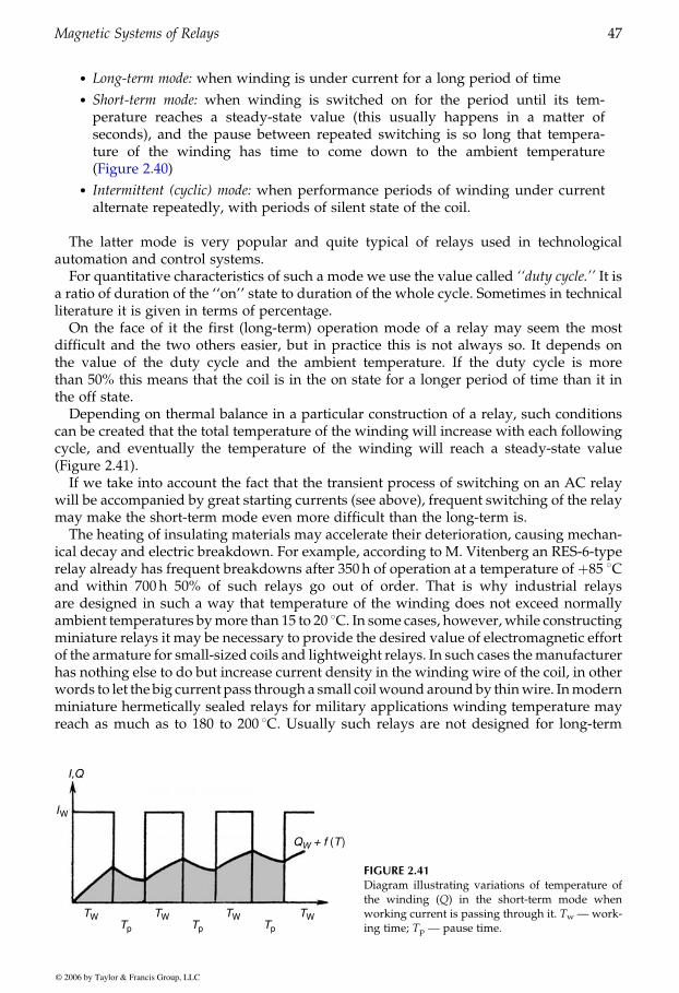
. Long-term mode: when winding is under current for a long period of time
. Short-term mode: when winding is switched on for the period until its tem-perature reaches a steady-state value (this usually happens in a matter ofseconds), and the pause between repeated switching is so long that tempera-ture of the winding has time to come down to the ambient temperature
. Intermittent (cyclic) mode: when performance periods of winding under currentalternate repeatedly, with periods of silent state of the coil.
The latter mode is very popular and quite typical of relays used in technologicalautomation and control systems.
For quantitative characteristics of such a mode we use the value called ‘‘duty cycle.’’ It isa ratio of duration of the ‘‘on’’ state to duration of the whole cycle. Sometimes in technicalliterature it is given in terms of percentage.
On the face of it the first (long-term) operation mode of a relay may seem the mostdifficult and the two others easier, but in practice this is not always so. It depends onthe value of the duty cycle and the ambient temperature. If the duty cycle is morethan 50% this means that the coil is in the on state for a longer period of time than it inthe off state.
Depending on thermal balance in a particular construction of a relay, such conditionscan be created that the total temperature of the winding will increase with each followingcycle, and eventually the temperature of the winding will reach a steady-state value(Figure 2.41).
If we take into account the fact that the transient process of switching on an AC relaywill be accompanied by great starting currents (see above), frequent switching of the relaymay make the short-term mode even more difficult than the long-term is.
The heating of insulating materials may accelerate their deterioration, causing mechan-ical decay and electric breakdown. For example, according to M. Vitenberg an RES-6-typerelay already has frequent breakdowns after 350 h of operation at a temperature of þ85 8Cand within 700 h 50% of such relays go out of order. That is why industrial relaysare designed in such a way that temperature of the winding does not exceed normallyambient temperatures bymore than 15 to 20 8C. In some cases, however, while constructingminiature relays it may be necessary to provide the desired value of electromagnetic effortof the armature for small-sized coils and lightweight relays. In such cases themanufacturerhas nothing else to do but increase current density in the winding wire of the coil, in otherwords to let the big current pass through a small coilwound around by thinwire. Inmodernminiature hermetically sealed relays for military applications winding temperature mayreach as much as to 180 to 200 8C. Usually such relays are not designed for long-term
I,Q
IW
TW TW TW TWTp Tp Tp
QW + f (T)
FIGURE 2.41Diagram illustrating variations of temperature ofthe winding (Q) in the short-term mode whenworking current is passing through it. Tw — work-ing time; Tp — pause time.
GUREVICH / Electric Relays: Principles and Practises DK884X_c002 Final Proof page 47 31.10.2005 8:38am
Magnetic Systems of Relays 47
© 2006 by Taylor & Francis Group, LLC
(Figure 2.40)

energization, and are used in on-board systems of single-missionweapons such asmissiles,torpedoes, etc.
When browsing through specifications of such relays (only for relays produced inRussia) one may come across a value called ‘‘continuous (or total) time of a relay underworking voltage (current) at working ambient temperature.’’ For some types of light-weight miniature hermetic relays this time may only be some hundreds of hours. Unfor-tunately, most of the western relay manufacturers do not usually mark this parameter intheir catalogs.
GUREVICH / Electric Relays: Principles and Practises DK884X_c002 Final Proof page 48 31.10.2005 8:38am
48 Electric Relays: Principles and applications
© 2006 by Taylor & Francis Group, LLC
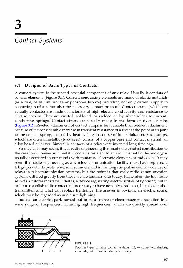
3Contact Systems
3.1 Designs of Basic Types of Contacts
A contact system is the second essential component of any relay. Usually it consists ofseveral elements (Figure 3.1). Current-conducting elements are made of elastic materials(as a rule, beryllium bronze or phosphor bronze) providing not only current supply tocontacting surfaces but also the necessary contact pressure. Contact straps (which areactually contacts) are made of materials of high electric conductivity and resistance toelectric erosion. They are riveted, soldered, or welded on by silver solder to current-conducting springs. Contact straps are usually made in the form of rivets or pins
because of the considerable increase in transient resistance of a rivet at the point of its jointto the contact spring, caused by heat cycling in course of its exploitation. Such straps,which are often bimetallic (two-layer), consist of a copper base and contact material, analloy based on silver. Bimetallic contacts of a relay were invented long time ago.
Strange as it may seem, it was radio engineering that made the greatest contribution tothe creation of powerful bimetallic contacts resistant to an arc. This field of technology isusually associated in our minds with miniature electronic elements or radio sets. It mayseem that radio engineering as a wireless communication facility must have replaced atelegraph with its posts, wire, and sounders and in the long run put an end to wide use ofrelays in telecommunication systems, but the point is that early radio communicationsystems differed greatly from those we are familiar with today. Remember, the first radioset was a ‘‘storm indicator,’’ that is, a device registering electric strikes of lightning, but inorder to establish radio contact it is necessary to have not only a radio set, but also a radio-transmitter, and what can replace lightning? The answer is obvious: an electric spark,which may be regarded as miniature lightning.
Indeed, an electric spark turned out to be a source of electromagnetic radiation in awide range of frequencies, including high frequencies, which are quickly spread over
5
1 2 3 4
FIGURE 3.1Popular types of relay contact systems. 1,2, — current-conductingelements; 3,4 — contact straps; 5 — stop.
GUREVICH / Electric Relays: Principles and Practises DK884X_c003 Final Proof page 49 29.10.2005 11:05pm
49© 2006 by Taylor & Francis Group, LLC
(Figure 3.2). Riveted attachment of contact straps is less reliable than welded attachment,
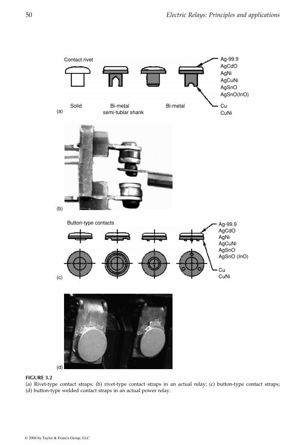
Contact rivet
Solid Bi-metalBi-metal semi-tublar shank
Ag-99.9AgCdOAgNiAgCuNiAgSnOAgSnO(InO)
CuCuNi(a)
(b)
Button-type contacts Ag-99.9AgCdOAgNiAgCuNiAgSnOAgSnO (InO)
CuCuNi(c)
(d)
FIGURE 3.2(a) Rivet-type contact straps; (b) rivet-type contact straps in an actual relay; (c) button-type contact straps;(d) button-type welded contact straps in an actual power relay.
GUREVICH / Electric Relays: Principles and Practises DK884X_c003 Final Proof page 50 29.10.2005 11:05pm
50 Electric Relays: Principles and applications
© 2006 by Taylor & Francis Group, LLC

long distances. A continuous pulsating arc strikes an electric circuit consisting of a coil, acapacitor, active resistance, an DC power source, and two carbon electrodes (Figure 3.3),and is a power source of radio waves.
The first development of the oscillating arc was done by the Danish scientist, ValdemarPoulsen. Australian born and Stanford educated Cyril Elwell came across Poulsen’sexperiments and at once realized their commercial potential. In 1909, with the supportof investors, he founded Federal Telegraph in San Francisco, in order to commerciallyexploit arc technology.
One technical drawback of that type of arc transmitter was that it was impossible toconnect a Morse key directly to the circuit of the electric arc in order to receive acontrolled (modulated) radio-signal, because the arc ran continuously and it was impos-sible to switch high powers (tens and hundreds of kilowatts) by means of a manualswitch.
Here a relay came in useful. Being connected to a DC source, its winding was also inseries with a Morse key. Referring to the schematic, note that the arc, denoted by ‘‘X,’’ isswitched by relay contacts, ‘‘K,’’ between the antenna circuit and the dummy load tunedto the same frequency as the antenna circuit (Figure 3.4).
In 1913 Elwell developed and demonstrated this technology to the US Navy. By 1921,80% of all commercial and military transmitters were of the arc variety. The capacity ofsuch transmitters was continuously growing and eventually reached one million watt
G
KA
B
C
L
–
+ FIGURE 3.3An oscillatory circuit with an arc is a power source of radiowaves.
A
L2
L1
K
C
R
FIGURE 3.4Schematic illustrating basic principles of operation of an arc transmitter of the early 19th century. X — arc;K — contacts of a modulator.
GUREVICH / Electric Relays: Principles and Practises DK884X_c003 Final Proof page 51 29.10.2005 11:06pm
Contact Systems 51
© 2006 by Taylor & Francis Group, LLC
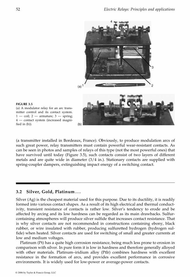
(a transmitter installed in Bordeaux, France). Obviously, to produce modulation arcs ofsuch great power, relay transmitters must contain powerful wear-resistant contacts. Ascan be seen in photos and samples of relays of this type (not the most powerful ones) thathave survived until today (Figure 3.5), such contacts consist of two layers of differentmetals and are quite wide in diameter (3/4 in.). Stationary contacts are supplied withspring-coupler dampers, extinguishing impact energy of a switching contact.
3.2 Silver, Gold, Platinum . . .
Silver (Ag) is the cheapest material used for this purpose. Due to its ductility, it is readilyformed into various contact shapes. As a result of its high electrical and thermal conduct-ivity, transient resistance of contacts is rather low. Silver’s tendency to erode and beaffected by arcing and its low hardness can be regarded as its main drawbacks. Sulfur-containing atmospheres will produce silver sulfide that increases contact resistance. Thatis why silver contacts are not recommended in constructions containing ebony, blackrubber, or wire insulated with rubber, producing sulfuretted hydrogen (hydrogen sul-fide) when heated. Silver contacts are used for switching of small and greater currents atlow and medium voltages.
Platinum (Pt) has a quite high corrosion resistance, being much less prone to erosion incomparison with silver. In pure form it is low in hardness and therefore generally alloyedwith other materials. Platinum–iridium alloy (PtIr) combines hardness with excellentresistance in the formation of arcs, and provides excellent performance in corrosiveenvironments. It is widely used for low-power or average-power contacts.
FIGURE 3.5(a) A modulator relay for an arc trans-mitter control and its contact system.1 — coil; 2 — armature; 3 — spring;4 — contact system (increased magni-fied in (b)). (b)
1 2
3
4
(a)
GUREVICH / Electric Relays: Principles and Practises DK884X_c003 Final Proof page 52 29.10.2005 11:06pm
52 Electric Relays: Principles and applications
© 2006 by Taylor & Francis Group, LLC
Tungsten is a very hard and refractory material. It is resistant to mechanical wear andwelding, but as a result of its tendency to form thick oxide surface films it also requireshigh contact forces. Its high resistance limits its area of application. Tungsten is usuallyused as an auxiliary contact in contact systems containing both main and auxiliary(arcing) contacts.
Silver–tungsten alloy (AgW) is hard, with high resistance to contact welding and ahigh melting temperature. Its drawbacks are a tendency to oxidation and elevatedresistance.
Silver–nickel alloy (AgNi) possesses good arc extinguishing properties and low oxida-tion, as well as high electrical conductivity similar to silver; however, it tends to formsulfide surface films. It is widely used for average-power contacts.
Silver–copper alloy (AgCu3) possesses high resistance to mechanical wear and a weakertendency to welding when compared to silver. Contact resistance is higher than that ofsilver.
Silver–palladium (AgPd) has quite high corrosion and sulfitation resistance, and is notprone to contact welding. Among its drawbacks is a tendency to absorb organic gases andto form a polymeric surface film. To prevent this it should be overlaid with gold, which isquite expensive.
Gold–silver (AuAg) possesses quite low and stable contact resistance, even with lowcurrents and voltages and low resistance to welding; therefore, this alloy is used forcontacts of measuring circuits with low currents and voltages.
Silver–cadmium oxide (AgCdO) is not an alloy, but rather a ceramic–metal compos-ition. Contacts are pressed from powder, then heated to high temperatures for sintering ofthe components, calibrated by additional swaging in molds and then annealed for relief ofwork hardening. This material possesses high resistance to arcing and to mechanical wearand is prone to welding. It has stable properties but its resistance is higher than that ofpure silver and it tends to form sulfide surface films. It is widely used for average andpower contacts.
Silver–tin oxide (AgSnO) has come to be considered a good alternative to the AgCdOcontacts described above. Over the past years the use of cadmium in contacts as well as inbatteries has been restricted in many areas of the world; therefore, tin oxide contacts (10%)which are about 15% harder than AgCdO are a good alternative. Also, the above contactsare good for high inrush loads, like tungsten lamps, where the steady-state current is low.
To save space in micro-miniature relays with gaps of hundredths of a millimeter,contacts are formed by pressing-out protrusions on the ends of a flat spring. Sometimesslightly deflected ends of such springs also serve as contacts. Obviously in such casescontact springs should be made of specific materials. As a rule those materials arecomplex alloys based on silver with admixtures of magnesium (0.15 to 0.3%), nickel (0.1to 0.25%), gold (1.5 to 2%), or zirconium (0.1 to 0.4%). Specific resistance of such alloys ishalf as much as that of typical contact springs with a beryllium bronze base, and that iswhy they can pass greater current. It is very essential when working with micro-mini-ature relays, to take into account the small size of their springs.
To enhance surface behavior of contacts, they are sometimes covered by gold orrhodium. Gold cover provides a clean surface, low resistance, and high stability ofweak-current contacts. Rhodium cover is much heavier than gold and provides higherresistance to mechanical wear, but due to its tendency to absorb gases and form polymericsurface films it can only be used in hermetic relays.
Contacts with a thin cover are not reliable because the thinnest layer protecting acontact from oxidation can easily be damaged in the course of exploitation, when contactsare stripped. Stripping without cover may be expedient only in cases of considerablesurface erosion. Stripping of unworn contacts with the help of a file or sandpaper only
GUREVICH / Electric Relays: Principles and Practises DK884X_c003 Final Proof page 53 29.10.2005 11:06pm
Contact Systems 53
© 2006 by Taylor & Francis Group, LLC
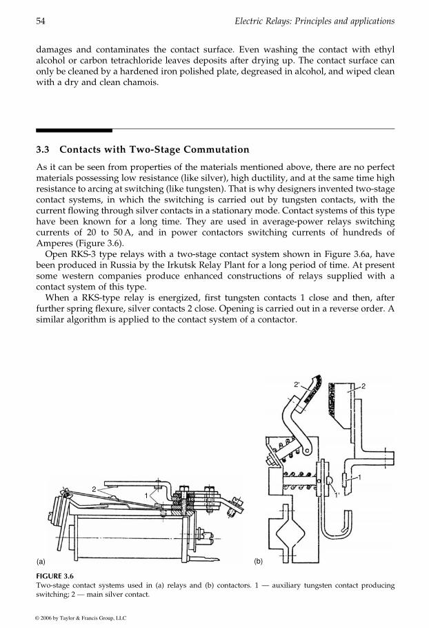
damages and contaminates the contact surface. Even washing the contact with ethylalcohol or carbon tetrachloride leaves deposits after drying up. The contact surface canonly be cleaned by a hardened iron polished plate, degreased in alcohol, and wiped cleanwith a dry and clean chamois.
3.3 Contacts with Two-Stage Commutation
As it can be seen from properties of the materials mentioned above, there are no perfectmaterials possessing low resistance (like silver), high ductility, and at the same time highresistance to arcing at switching (like tungsten). That is why designers invented two-stagecontact systems, in which the switching is carried out by tungsten contacts, with thecurrent flowing through silver contacts in a stationary mode. Contact systems of this typehave been known for a long time. They are used in average-power relays switchingcurrents of 20 to 50A, and in power contactors switching currents of hundreds ofAmperes (Figure 3.6).
Open RKS-3 type relays with a two-stage contact system shown in Figure 3.6a, havebeen produced in Russia by the Irkutsk Relay Plant for a long period of time. At presentsome western companies produce enhanced constructions of relays supplied with acontact system of this type.
When a RKS-type relay is energized, first tungsten contacts 1 close and then, afterfurther spring flexure, silver contacts 2 close. Opening is carried out in a reverse order. Asimilar algorithm is applied to the contact system of a contactor.
2
(a)
1 1'
2' 2
1
(b)
FIGURE 3.6Two-stage contact systems used in (a) relays and (b) contactors. 1 — auxiliary tungsten contact producingswitching; 2 — main silver contact.
GUREVICH / Electric Relays: Principles and Practises DK884X_c003 Final Proof page 54 29.10.2005 11:06pm
54 Electric Relays: Principles and applications
© 2006 by Taylor & Francis Group, LLC
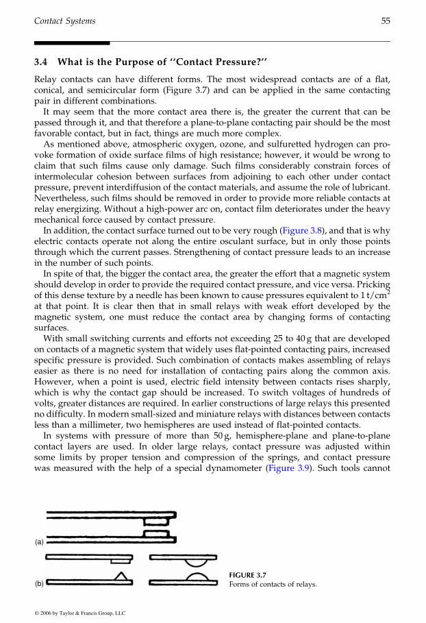
3.4 What is the Purpose of ‘‘Contact Pressure?’’
Relay contacts can have different forms. The most widespread contacts are of a flat,conical, and semicircular form (Figure 3.7) and can be applied in the same contactingpair in different combinations.
It may seem that the more contact area there is, the greater the current that can bepassed through it, and that therefore a plane-to-plane contacting pair should be the mostfavorable contact, but in fact, things are much more complex.
As mentioned above, atmospheric oxygen, ozone, and sulfuretted hydrogen can pro-voke formation of oxide surface films of high resistance; however, it would be wrong toclaim that such films cause only damage. Such films considerably constrain forces ofintermolecular cohesion between surfaces from adjoining to each other under contactpressure, prevent interdiffusion of the contact materials, and assume the role of lubricant.Nevertheless, such films should be removed in order to provide more reliable contacts atrelay energizing. Without a high-power arc on, contact film deteriorates under the heavymechanical force caused by contact pressure.
electric contacts operate not along the entire osculant surface, but in only those pointsthrough which the current passes. Strengthening of contact pressure leads to an increasein the number of such points.
In spite of that, the bigger the contact area, the greater the effort that a magnetic systemshould develop in order to provide the required contact pressure, and vice versa. Prickingof this dense texture by a needle has been known to cause pressures equivalent to 1 t/cm2
at that point. It is clear then that in small relays with weak effort developed by themagnetic system, one must reduce the contact area by changing forms of contactingsurfaces.
With small switching currents and efforts not exceeding 25 to 40 g that are developedon contacts of a magnetic system that widely uses flat-pointed contacting pairs, increasedspecific pressure is provided. Such combination of contacts makes assembling of relayseasier as there is no need for installation of contacting pairs along the common axis.However, when a point is used, electric field intensity between contacts rises sharply,which is why the contact gap should be increased. To switch voltages of hundreds ofvolts, greater distances are required. In earlier constructions of large relays this presentedno difficulty. In modern small-sized and miniature relays with distances between contactsless than a millimeter, two hemispheres are used instead of flat-pointed contacts.
In systems with pressure of more than 50 g, hemisphere-plane and plane-to-planecontact layers are used. In older large relays, contact pressure was adjusted withinsome limits by proper tension and compression of the springs, and contact pressure
(a)
(b)FIGURE 3.7Forms of contacts of relays.
GUREVICH / Electric Relays: Principles and Practises DK884X_c003 Final Proof page 55 29.10.2005 11:06pm
Contact Systems 55
© 2006 by Taylor & Francis Group, LLC
In addition, the contact surface turned out to be very rough (Figure 3.8), and that is why
was measured with the help of a special dynamometer (Figure 3.9). Such tools cannot
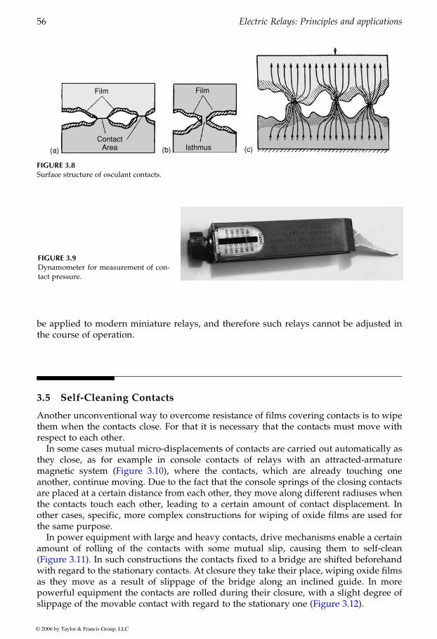
be applied to modern miniature relays, and therefore such relays cannot be adjusted inthe course of operation.
3.5 Self-Cleaning Contacts
Another unconventional way to overcome resistance of films covering contacts is to wipethem when the contacts close. For that it is necessary that the contacts must move withrespect to each other.
In some cases mutual micro-displacements of contacts are carried out automatically asthey close, as for example in console contacts of relays with an attracted-armaturemagnetic system the contacts, which are already touching one
are placed at a certain distance from each other, they move along different radiuses whenthe contacts touch each other, leading to a certain amount of contact displacement. Inother cases, specific, more complex constructions for wiping of oxide films are used forthe same purpose.
In power equipment with large and heavy contacts, drive mechanisms enable a certainamount of rolling of the contacts with some mutual slip, causing them to self-clean
with regard to the stationary contacts. At closure they take their place, wiping oxide films
powerful equipment the contacts are rolled during their closure, with a slight degree of
Film
ContactArea(a)
Film
Isthmus(b) (c)
FIGURE 3.8Surface structure of osculant contacts.
FIGURE 3.9Dynamometer for measurement of con-tact pressure.
GUREVICH / Electric Relays: Principles and Practises DK884X_c003 Final Proof page 56 29.10.2005 11:06pm
56 Electric Relays: Principles and applications
© 2006 by Taylor & Francis Group, LLC
(Figure whereanother, continue moving. Due to the fact that the console springs of the closing contacts
as they move as a result of slippage of the bridge along an inclined guide. In more
3.10),
(Figure 3.11). In such constructions the contacts fixed to a bridge are shifted beforehand
slippage of the movable contact with regard to the stationary one (Figure 3.12).
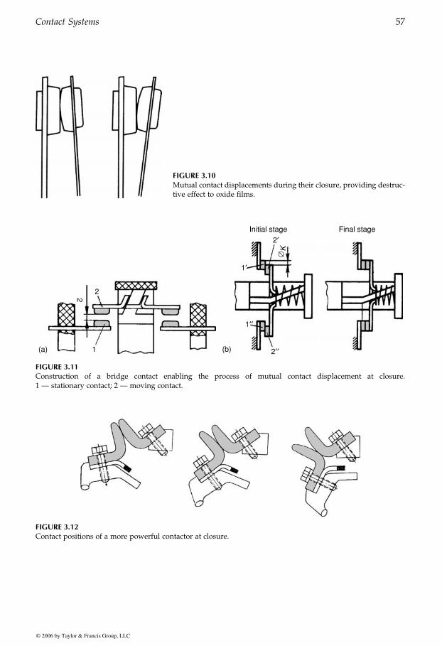
FIGURE 3.10Mutual contact displacements during their closure, providing destruc-tive effect to oxide films.
22
1(a)
Initial stage
2′
1′
1′′
2′′
Final stage
(b)
∅K
FIGURE 3.11Construction of a bridge contact enabling the process of mutual contact displacement at closure.1 — stationary contact; 2 — moving contact.
FIGURE 3.12Contact positions of a more powerful contactor at closure.
GUREVICH / Electric Relays: Principles and Practises DK884X_c003 Final Proof page 57 29.10.2005 11:06pm
Contact Systems 57
© 2006 by Taylor & Francis Group, LLC

Depending on the type of contacting surfaces, different kinds of contacts are used indifferent relays: point contacts, plane contacts, and line contacts (Figure 3.13). Each ofthese contact types is implemented in different construction diagrams of a contact system
3.6 Self-Adjusting Contacts
In order to enhance the switching capability of the relay, the contact system is made in the
serial contact gaps. In this case an open relay of quite a small size (49 � 36 � 41mm)switches current up to 30A, voltage up to 600V, and power up to 1 kW.
Unlike contacts fixed on long and flexible console springs, a bridge contact is a hardcomponent and requires additional elements to provide for reliable compression of themovable contact into the stationary one, for compensation of shock at closure, and also forautomatic installation of the bridge in case there are technological variations of sizes,assembling inaccuracies and additional gaps emerging in the course of exploitation of therelay. All of these requirements are in fact fulfilled in the simplest constructions by means
In some constructions of power relays designed in the 1950s and 1960s, self-installingbridge contacts were made as separate modules of a single-contact (Figure 3.17b) or multi-contact (Figure 3.17c) relay system. Despite the fact that the relays shown in Figure 3.17band c look quite big and seemingly old-fashioned, General Electric Co., continues toproduce them and include them in some types of power equipment it supplies today.The author came across relays of this type, for example, on a new gas-turbine powerstation still in the running-in process in 2004.
3.7 When Power does not Equal Multiplication by Current and Voltage
If on the miniature relay it is written: 250V, 5A it yet does not mean, that this relay is ableto switch load 1250W, that is, 250V � 5A 6¼ 1250W. Why? Because 250V in our sample isthe maximal switching voltage and 5A is the maximal switching current. It has not been
(a)
(b)
(c)
FIGURE 3.13Various types of contacts used in relays. 1 — point contacts (for currents up to 20–40A); 2 — line contacts;3 — plane contacts.
GUREVICH / Electric Relays: Principles and Practises DK884X_c003 Final Proof page 58 29.10.2005 11:06pm
58 Electric Relays: Principles and applications
© 2006 by Taylor & Francis Group, LLC
(Figure 3.14). In sensitive polarized relays (referred to below) a contact system usuallylooks as it appears in Figure 3.15.
form of a bridge (Figure 3.16). Power, partitioned by the contact, is shared by the two
of a spring abutting from the central part of the bridge (Figure 3.17).
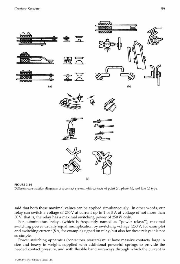
said that both these maximal values can be applied simultaneously. In other words, ourrelay can switch a voltage of 250V at current up to 1 or 5A at voltage of not more than50V, that is, the relay has a maximal switching power of 250W only.
For subminiature relays (which is frequently named as ‘‘power relays’’), maximalswitching power usually equal multiplication by switching voltage (250V, for example)and switching current (8A, for example) signed on relay, but also for these relays it is notso simple.
Power switching apparatus (contactors, starters) must have massive contacts, large insize and heavy in weight, supplied with additional powerful springs to provide theneeded contact pressure, and with flexible band wireways through which the current is
(a) (b)
(c)
FIGURE 3.14Different construction diagrams of a contact system with contacts of point (a), plane (b), and line (c) type.
GUREVICH / Electric Relays: Principles and Practises DK884X_c003 Final Proof page 59 29.10.2005 11:06pm
Contact Systems 59
© 2006 by Taylor & Francis Group, LLC
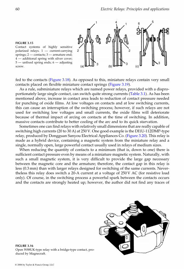
As a rule, subminiature relays which are named power relays, provided with a dispro-
mentioned above, increase in contact area leads to reduction of contact pressure neededfor punching of oxide films. At low voltages on contacts and at low switching currents,this can cause an interruption of the switching process; however, if such relays are notused for switching low voltages and small currents, the oxide films will deterioratebecause of thermal impact of arcing on contacts at the time of switching. In addition,massive contacts contribute to better cooling of the arc and to its quick starvation.
switching high currents (20 to 30A) at 250V. One good example is the DI1U-112DMP-type
made as a hybrid device, containing a magnetic system from the miniature relay and asingle, normally open, large powerful contact usually used in relays of medium sizes.
When reducing the quantity of contacts to a minimum (that is, down to one) there issufficient contact pressure even by means of a miniature magnetic system. Naturally, withsuch a small magnetic system, it is very difficult to provide the large gap necessarybetween the magnetic core and the armature; therefore, the contact gap in this relay isless (0.3mm) than with larger relays designed for switching of the same currents. Never-theless this relay does switch a 20-A current at a voltage of 250V AC (for resistive loadonly). Of course, in the switching process a powerful spark between the contacts occursand the contacts are strongly heated up; however, the author did not find any traces of
FIGURE 3.15Contact systems of highly sensitivepolarized relays. 1 — current-carryingsprings; 2 — contacts; 3 — armature end;4 — additional spring with silver cover;5 — unfixed spring ends; 6 — adjustingscrew.
1
2
3 3
2
14 6 5
3(a) (b) (c)
FIGURE 3.16Open W88UK-type relay with a bridge-type contact, pro-duced by Magnecraft.
GUREVICH / Electric Relays: Principles and Practises DK884X_c003 Final Proof page 60 29.10.2005 11:06pm
60 Electric Relays: Principles and applications
© 2006 by Taylor & Francis Group, LLC
portionately large single contact, can switch quite strong currents (Table 3.1). As has been
fed to the contacts (Figure 3.18). As opposed to this, miniature relays contain very small
Sometimes one can find relayswith relatively small dimensions that are really capable of
contacts placed on flexible miniature contact springs (Figure 3.19).
relay, produced by Dongguan Sanyou Electrical Appliances Co. (Figure 3.20). This relay is
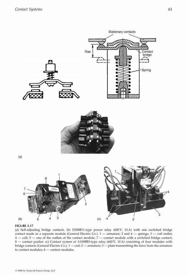
Gap
Stationary contacts
Contactbridge
Spring
(a)
18
7
5
6
4 3
2
(b)
1
4 2
3
4
(c)
FIGURE 3.17(a) Self-adjusting bridge contacts. (b) D300B11-type power relay (600V, 10A) with one switched bridgecontact made as a separate module (General Electric Co.). 1 — armature; 2 and 6 — springs; 3 — coil outlet;4 — coil; 5 — one of the outlets of the contact module; 7 — contact module with a switched bridge contact;8 — contact pusher. (c) Contact system of A100BB3-type relay (600V, 10A) consisting of four modules withbridge contacts (General Electric Co.). 1 — coil; 2 — armature; 3 — plate transmitting the force from the armatureto contact modules; 4 — contact modules.
GUREVICH / Electric Relays: Principles and Practises DK884X_c003 Final Proof page 61 29.10.2005 11:06pm
Contact Systems 61
© 2006 by Taylor & Francis Group, LLC
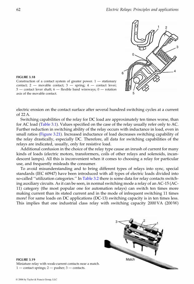
electric erosion on the contact surface after several hundred switching cycles at a currentof 22A.
Switching capabilities of the relay for DC load are approximately ten times worse, than
Further reduction in switching ability of the relay occurs with inductance in load, even in
the relay drastically, especially DC. Therefore, all data for switching capabilities of therelays are indicated, usually, only for resistive load.
Additional confusion in the choice of the relay type cause an inrush of current for manykinds of loads (electric motors, transformers, coils of other relays and solenoids, incan-descent lamps). All this is inconvenient when it comes to choosing a relay for particularuse, and frequently misleads the consumer.
To avoid misunderstanding and to bring different types of relays into sync, specialstandards (IEC 60947) have been introduced with all types of electric loads divided into
ing auxiliary circuits. As it can be seen, in normal switchingmode a relay of an AC-15 (AC-11) category (the most popular one for automation relays) can switch ten times moremaking current than its stated current and in the mode of infrequent switching 11 timesmore! For same loads on DC applications (DC-13) switching capacity is in ten times less.This implies that one industrial class relay with switching capacity 2000VA (200W)
FIGURE 3.18Construction of a contact system of greater power. 1 — stationarycontact; 2 — movable contact; 3 — spring; 4 — contact lever;5 — contact lever shaft; 6 — flexible band wireways; 0 — rotationaxis of the movable contact.
1 2
3
4
5
6
0
FIGURE 3.19Miniature relay with weak-current contacts near a match.1 — contact springs; 2 — pusher; 3 — contacts.
3 21
Match
GUREVICH / Electric Relays: Principles and Practises DK884X_c003 Final Proof page 62 29.10.2005 11:06pm
62 Electric Relays: Principles and applications
© 2006 by Taylor & Francis Group, LLC
for AC load (Table 3.1). Values specified on the case of the relay usually refer only to AC.
so-called ‘‘utilization categories.’’ In Table 3.2 there is some data for relay contacts switch-
small ratios (Figure 3.21). Increased inductance of load decreases switching capability of
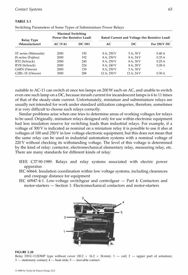
suitable to AC-11 can switch at once ten lamps on 200W each on AC, and unable to switcheven one such lamp on aDC, because inrush current for incandescent lamps is 6 to 11 timesof that of the steady-state current. Unfortunately, miniature and subminiature relays areusually not intended for work under standard utilization categories, therefore, sometimesit is very difficult to choose such relays correctly.
Similar problems arise when one tries to determine areas of working voltages for relaysto be used. Originally, miniature relays designed only for use within electronic equipmenthad less insulation reserve for switching loads than industrial relays. For example, if avoltage of 300V is indicated as nominal on a miniature relay it is possible to use it also atvoltages of 100 and 250V in low voltage electronic equipment, but this does not mean thatthe same relay can be used in industrial automation systems with a nominal voltage of220V without checking its withstanding voltage. The level of this voltage is determinedby the kind of relay: contactor, electromechanical elementary relay, measuring relay, etc.There are many standards for different kinds of relay:
IEEE C37.90-1989. Relays and relay systems associated with electric powerapparatus
IEC 60664. Insulation coordination within low voltage systems, including clearancesand creepage distance for equipment
IEC 60947-4-1. Low-voltage switchgear and controlgear — Part 4: Contactors andmotor-starters — Section 1: Electromechanical contactors and motor-starters
TABLE 3.1
Switching Parameters of Some Types of Subminiature Power Relays
Relay Type
Maximal Switching
Power (for Resistive Load) Rated Current and Voltage (for Resistive Load)
(Manufacturer) AC (VA) DC (W) AC DC For 250V DC
ST series (Matsusita) 2000 150 8A; 250V 5A; 30V 0.40AJS series (Fujitsu) 2000 192 8A; 250V 8A; 24V 0.35ART2 (Schrack) 2000 240 8A; 250V 8A; 30V 0.25ARYII (Schrack) 2000 224 8A; 240V 8A; 28V 0.28AG6RN (Omron) 2000 150 8A; 250V 5A; 30V –G2RL-1E (Omron) 3000 288 12A; 250V 12A; 24V 0.30A
4
5
3
2
1
FIGURE 3.20Relay DI1U-112DMP type without cover (30.2 � 16.2 � 26mm). 1 — coil; 2 — upper part of armature;3 — stationary contact; 4 — heat sink; 5 — movable contact.
GUREVICH / Electric Relays: Principles and Practises DK884X_c003 Final Proof page 63 29.10.2005 11:06pm
Contact Systems 63
© 2006 by Taylor & Francis Group, LLC
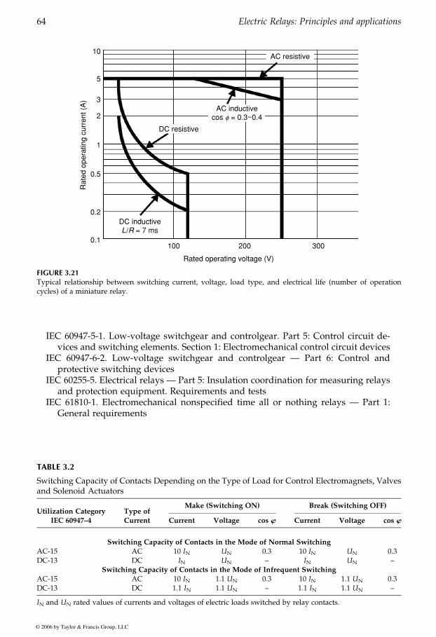
IEC 60947-5-1. Low-voltage switchgear and controlgear. Part 5: Control circuit de-vices and switching elements. Section 1: Electromechanical control circuit devices
IEC 60947-6-2. Low-voltage switchgear and controlgear — Part 6: Control andprotective switching devices
IEC 60255-5. Electrical relays — Part 5: Insulation coordination for measuring relaysand protection equipment. Requirements and tests
IEC 61810-1. Electromechanical nonspecified time all or nothing relays — Part 1:General requirements
10
5
3
2
1
0.5
0.2
0.1100 200 300
Rated operating voltage (V)
Rat
ed o
pera
ting
curr
ent (
A)
AC resistive
AC inductivecos f = 0.3~0.4
DC resistive
DC inductiveL/R = 7 ms
FIGURE 3.21Typical relationship between switching current, voltage, load type, and electrical life (number of operationcycles) of a miniature relay.
TABLE 3.2
Switching Capacity of Contacts Depending on the Type of Load for Control Electromagnets, Valvesand Solenoid Actuators
Utilization Category
IEC 60947–4
Type of
Current
Make (Switching ON) Break (Switching OFF)
Current Voltage cos w Current Voltage cos w
Switching Capacity of Contacts in the Mode of Normal Switching
AC-15 AC 10 IN UN 0.3 10 IN UN 0.3DC-13 DC IN UN – IN UN –
Switching Capacity of Contacts in the Mode of Infrequent Switching
AC-15 AC 10 IN 1.1 UN 0.3 10 IN 1.1 UN 0.3DC-13 DC 1.1 IN 1.1 UN – 1.1 IN 1.1 UN –
IN and UN rated values of currents and voltages of electric loads switched by relay contacts.
GUREVICH / Electric Relays: Principles and Practises DK884X_c003 Final Proof page 64 29.10.2005 11:06pm
64 Electric Relays: Principles and applications
© 2006 by Taylor & Francis Group, LLC
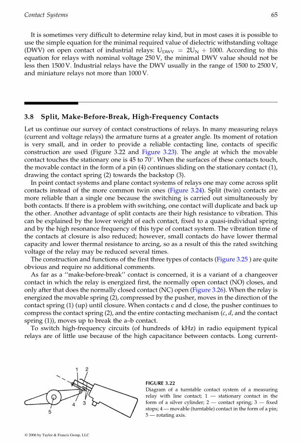
It is sometimes very difficult to determine relay kind, but in most cases it is possible touse the simple equation for the minimal required value of dielectric withstanding voltage(DWV) on open contact of industrial relays: UDWV ¼ 2UN þ 1000. According to thisequation for relays with nominal voltage 250V, the minimal DWV value should not beless then 1500V. Industrial relays have the DWV usually in the range of 1500 to 2500V,and miniature relays not more than 1000V.
3.8 Split, Make-Before-Break, High-Frequency Contacts
Let us continue our survey of contact constructions of relays. In many measuring relays(current and voltage relays) the armature turns at a greater angle. Its moment of rotationis very small, and in order to provide a reliable contacting line, contacts of specific
contact touches the stationary one is 45 to 708. When the surfaces of these contacts touch,the movable contact in the form of a pin (4) continues sliding on the stationary contact (1),drawing the contact spring (2) towards the backstop (3).
In point contact systems and plane contact systems of relays one may come across split
more reliable than a single one because the switching is carried out simultaneously byboth contacts. If there is a problem with switching, one contact will duplicate and back upthe other. Another advantage of split contacts are their high resistance to vibration. Thiscan be explained by the lower weight of each contact, fixed to a quasi-individual springand by the high resonance frequency of this type of contact system. The vibration time ofthe contacts at closure is also reduced; however, small contacts do have lower thermalcapacity and lower thermal resistance to arcing, so as a result of this the rated switchingvoltage of the relay may be reduced several times.
obvious and require no additional comments.As far as a ‘‘make-before-break’’ contact is concerned, it is a variant of a changeover
contact in which the relay is energized first, the normally open contact (NO) closes, and
energized the movable spring (2), compressed by the pusher, moves in the direction of thecontact spring (1) (up) until closure. When contacts c and d close, the pusher continues tocompress the contact spring (2), and the entire contacting mechanism (c, d, and the contactspring (1)), moves up to break the a–b contact.
To switch high-frequency circuits (of hundreds of kHz) in radio equipment typicalrelays are of little use because of the high capacitance between contacts. Long current-
1 2
4 3
5
FIGURE 3.22Diagram of a turntable contact system of a measuringrelay with line contact; 1 — stationary contact in theform of a silver cylinder; 2 — contact spring; 3 — fixedstops; 4 —movable (turntable) contact in the form of a pin;5 — rotating axis.
GUREVICH / Electric Relays: Principles and Practises DK884X_c003 Final Proof page 65 29.10.2005 11:06pm
Contact Systems 65
© 2006 by Taylor & Francis Group, LLC
construction are used (Figure 3.22 and Figure 3.23). The angle at which the movable
contacts instead of the more common twin ones (Figure 3.24). Split (twin) contacts are
The construction and functions of the first three types of contacts (Figure 3.25 ) are quite
only after that does the normally closed contact (NC) open (Figure 3.26). When the relay is
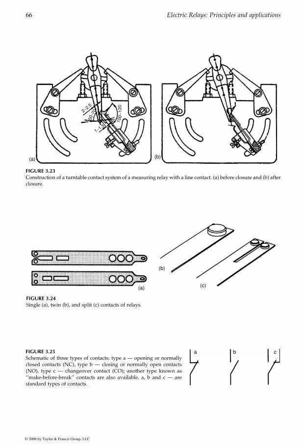
2−2.5
100
− 120
50−7
0
1−1.5
(a) (b)
FIGURE 3.23Construction of a turntable contact system of a measuring relay with a line contact. (a) before closure and (b) afterclosure.
(b)
(a) (c)
FIGURE 3.24Single (a), twin (b), and split (c) contacts of relays.
FIGURE 3.25Schematic of three types of contacts: type a — opening or normallyclosed contacts (NC), type b — closing or normally open contacts(NO), type c — changeover contact (CO); another type known as‘‘make-before-break’’ contacts are also available. a, b and c — arestandard types of contacts.
a b c
GUREVICH / Electric Relays: Principles and Practises DK884X_c003 Final Proof page 66 29.10.2005 11:06pm
66 Electric Relays: Principles and applications
© 2006 by Taylor & Francis Group, LLC
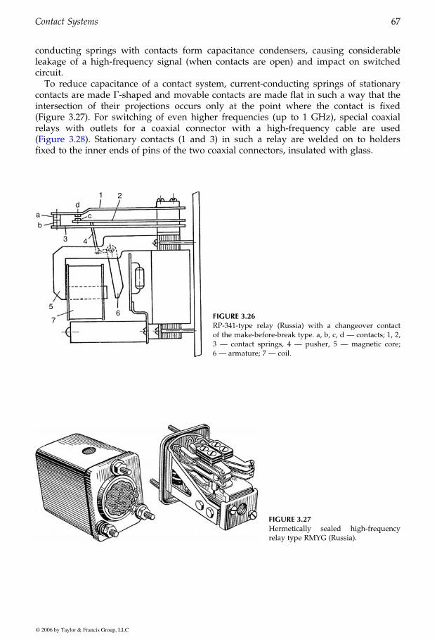
conducting springs with contacts form capacitance condensers, causing considerableleakage of a high-frequency signal (when contacts are open) and impact on switchedcircuit.
To reduce capacitance of a contact system, current-conducting springs of stationarycontacts are made G-shaped and movable contacts are made flat in such a way that theintersection of their projections occurs only at the point where the contact is fixed(Figure 3.27). For switching of even higher frequencies (up to 1 GHz), special coaxialrelays with outlets for a coaxial connector with a high-frequency cable are used
fixed to the inner ends of pins of the two coaxial connectors, insulated with glass.
1 2d
ab
3 4
5
76
c
FIGURE 3.26RP-341-type relay (Russia) with a changeover contactof the make-before-break type. a, b, c, d — contacts; 1, 2,3 — contact springs, 4 — pusher, 5 — magnetic core;6 — armature; 7 — coil.
FIGURE 3.27Hermetically sealed high-frequencyrelay type RMYG (Russia).
GUREVICH / Electric Relays: Principles and Practises DK884X_c003 Final Proof page 67 29.10.2005 11:06pm
Contact Systems 67
© 2006 by Taylor & Francis Group, LLC
(Figure 3.28). Stationary contacts (1 and 3) in such a relay are welded on to holders
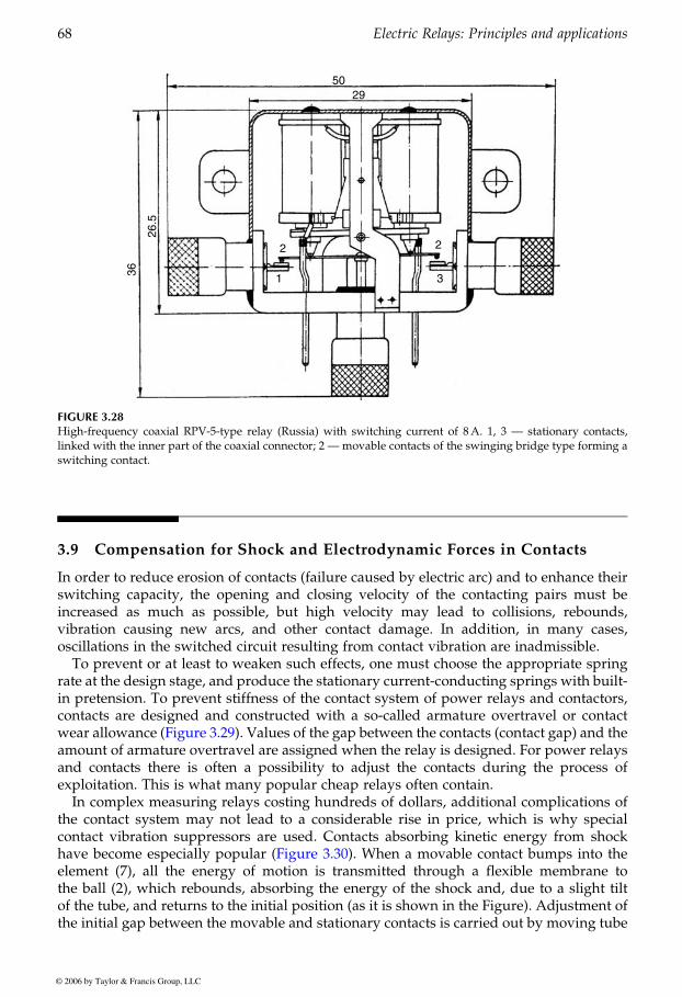
3.9 Compensation for Shock and Electrodynamic Forces in Contacts
In order to reduce erosion of contacts (failure caused by electric arc) and to enhance theirswitching capacity, the opening and closing velocity of the contacting pairs must beincreased as much as possible, but high velocity may lead to collisions, rebounds,vibration causing new arcs, and other contact damage. In addition, in many cases,oscillations in the switched circuit resulting from contact vibration are inadmissible.
To prevent or at least to weaken such effects, one must choose the appropriate springrate at the design stage, and produce the stationary current-conducting springs with built-in pretension. To prevent stiffness of the contact system of power relays and contactors,contacts are designed and constructed with a so-called armature overtravel or contact
amount of armature overtravel are assigned when the relay is designed. For power relaysand contacts there is often a possibility to adjust the contacts during the process ofexploitation. This is what many popular cheap relays often contain.
In complex measuring relays costing hundreds of dollars, additional complications ofthe contact system may not lead to a considerable rise in price, which is why specialcontact vibration suppressors are used. Contacts absorbing kinetic energy from shock
element (7), all the energy of motion is transmitted through a flexible membrane tothe ball (2), which rebounds, absorbing the energy of the shock and, due to a slight tiltof the tube, and returns to the initial position (as it is shown in the Figure). Adjustment ofthe initial gap between the movable and stationary contacts is carried out by moving tube
50
36
26.5
29
2
1 3
2
FIGURE 3.28High-frequency coaxial RPV-5-type relay (Russia) with switching current of 8A. 1, 3 — stationary contacts,linked with the inner part of the coaxial connector; 2 — movable contacts of the swinging bridge type forming aswitching contact.
GUREVICH / Electric Relays: Principles and Practises DK884X_c003 Final Proof page 68 29.10.2005 11:06pm
68 Electric Relays: Principles and applications
© 2006 by Taylor & Francis Group, LLC
wear allowance (Figure 3.29). Values of the gap between the contacts (contact gap) and the
have become especially popular (Figure 3.30). When a movable contact bumps into the
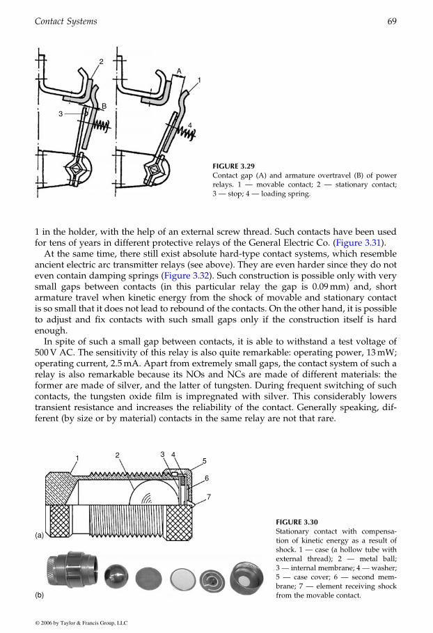
1 in the holder, with the help of an external screw thread. Such contacts have been used
At the same time, there still exist absolute hard-type contact systems, which resembleancient electric arc transmitter relays (see above). They are even harder since they do not
small gaps between contacts (in this particular relay the gap is 0.09mm) and, shortarmature travel when kinetic energy from the shock of movable and stationary contactis so small that it does not lead to rebound of the contacts. On the other hand, it is possibleto adjust and fix contacts with such small gaps only if the construction itself is hardenough.
In spite of such a small gap between contacts, it is able to withstand a test voltage of500V AC. The sensitivity of this relay is also quite remarkable: operating power, 13mW;operating current, 2.5mA. Apart from extremely small gaps, the contact system of such arelay is also remarkable because its NOs and NCs are made of different materials: theformer are made of silver, and the latter of tungsten. During frequent switching of suchcontacts, the tungsten oxide film is impregnated with silver. This considerably lowerstransient resistance and increases the reliability of the contact. Generally speaking, dif-ferent (by size or by material) contacts in the same relay are not that rare.
2
3B
A1
4
FIGURE 3.29Contact gap (A) and armature overtravel (B) of powerrelays. 1 — movable contact; 2 — stationary contact;3 — stop; 4 — loading spring.
1 2 3 45
6
7
(a)
(b)
FIGURE 3.30Stationary contact with compensa-tion of kinetic energy as a result ofshock. 1 — case (a hollow tube withexternal thread); 2 — metal ball;3 — internal membrane; 4 — washer;5 — case cover; 6 — second mem-brane; 7 — element receiving shockfrom the movable contact.
GUREVICH / Electric Relays: Principles and Practises DK884X_c003 Final Proof page 69 29.10.2005 11:07pm
Contact Systems 69
© 2006 by Taylor & Francis Group, LLC
for tens of years in different protective relays of the General Electric Co. (Figure 3.31).
even contain damping springs (Figure 3.32). Such construction is possible only with very
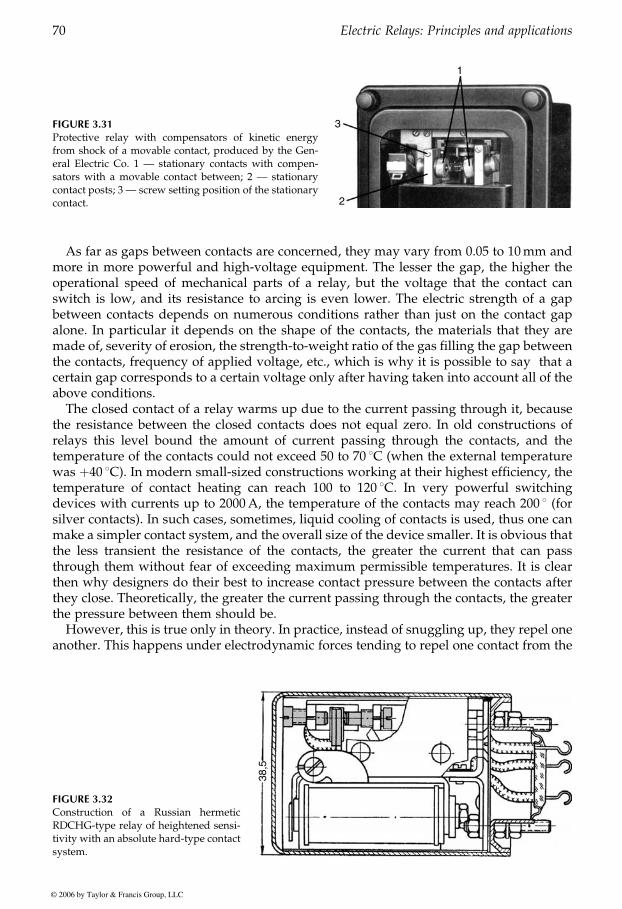
As far as gaps between contacts are concerned, they may vary from 0.05 to 10mm andmore in more powerful and high-voltage equipment. The lesser the gap, the higher theoperational speed of mechanical parts of a relay, but the voltage that the contact canswitch is low, and its resistance to arcing is even lower. The electric strength of a gapbetween contacts depends on numerous conditions rather than just on the contact gapalone. In particular it depends on the shape of the contacts, the materials that they aremade of, severity of erosion, the strength-to-weight ratio of the gas filling the gap betweenthe contacts, frequency of applied voltage, etc., which is why it is possible to say that acertain gap corresponds to a certain voltage only after having taken into account all of theabove conditions.
The closed contact of a relay warms up due to the current passing through it, becausethe resistance between the closed contacts does not equal zero. In old constructions ofrelays this level bound the amount of current passing through the contacts, and thetemperature of the contacts could not exceed 50 to 70 8C (when the external temperaturewas þ40 8C). In modern small-sized constructions working at their highest efficiency, thetemperature of contact heating can reach 100 to 120 8C. In very powerful switchingdevices with currents up to 2000A, the temperature of the contacts may reach 200 8 (forsilver contacts). In such cases, sometimes, liquid cooling of contacts is used, thus one canmake a simpler contact system, and the overall size of the device smaller. It is obvious thatthe less transient the resistance of the contacts, the greater the current that can passthrough them without fear of exceeding maximum permissible temperatures. It is clearthen why designers do their best to increase contact pressure between the contacts afterthey close. Theoretically, the greater the current passing through the contacts, the greaterthe pressure between them should be.
However, this is true only in theory. In practice, instead of snuggling up, they repel oneanother. This happens under electrodynamic forces tending to repel one contact from the
FIGURE 3.31Protective relay with compensators of kinetic energyfrom shock of a movable contact, produced by the Gen-eral Electric Co. 1 — stationary contacts with compen-sators with a movable contact between; 2 — stationarycontact posts; 3 — screw setting position of the stationarycontact.
1
3
2
FIGURE 3.32Construction of a Russian hermeticRDCHG-type relay of heightened sensi-tivity with an absolute hard-type contactsystem.
38,5
GUREVICH / Electric Relays: Principles and Practises DK884X_c003 Final Proof page 70 29.10.2005 11:07pm
70 Electric Relays: Principles and applications
© 2006 by Taylor & Francis Group, LLC
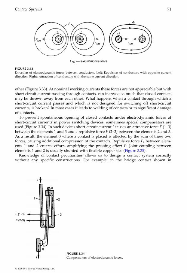
other (Figure 3.33). At nominal working currents these forces are not appreciable but withshort-circuit current passing through contacts, can increase so much that closed contactsmay be thrown away from each other. What happens when a contact through which ashort-circuit current passes and which is not designed for switching off short-circuitcurrents, is broken? In most cases it leads to welding of contacts or to significant damageof contacts.
To prevent spontaneous opening of closed contacts under electrodynamic forces ofshort-circuit currents in power switching devices, sometimes special compensators areused (Figure 3.34). In such devices short-circuit current I causes an attractive force F (1–3)between the elements 1 and 3 and a repulsive force F (2–3) between the elements 2 and 3.As a result, the element 3 where a contact is placed is affected by the sum of these twoforces, causing additional compression of the contacts. Repulsive force F2 between elem-ents 1 and 2 creates efforts amplifying the pressing effort P. Joint coupling between
Knowledge of contact peculiarities allows us to design a contact system correctlywithout any specific constructions. For example, in the bridge contact shown in
+I --I +I --I
FEM
FEMFEM
FEM −− electromotive force
Φ Φ
FIGURE 3.33Direction of electrodynamic forces between conductors. Left: Repulsion of conductors with opposite currentdirection. Right: Attraction of conductors with the same current direction.
F (1-3)
1
0
2
3
K
I
I
F (2-3)
FIGURE 3.34Compensators of electrodynamic forces.
GUREVICH / Electric Relays: Principles and Practises DK884X_c003 Final Proof page 71 29.10.2005 11:07pm
Contact Systems 71
© 2006 by Taylor & Francis Group, LLC
elements 1 and 2 is usually shunted with flexible copper ties (Figure 3.35).

Figure 3.36 it is enough just to put the bridge form in a lower position relative to the top sothat electrodynamic force P2 can change the direction of its impact on the contacts. In thefirst case (Figure 3.36, left), this force is subtracted from force P of contact pressureprovided by the springs, while in the second case (Figure 3.36, right) this force is addedto the force P increased by the springs.
Moreover, due to the additional effort P2, one can select a pressing spring with a smallerforce leading to a diminution of the coil size and to facilitation of the magnetic system.
3.10 Sparking Contacts and their Control
As contacts to which working load voltage is applied close, they draw closer to each other.When the minimum distance (hundredth parts of a millimeter for low-voltage relays) isreached, electric breakdown of the gap between the contacts takes place. Discharge arisingfrom that does not pass to an arc because a movable contact can pass distances of hun-dredth parts of a millimeter very quickly, and when the contacts open, the dischargedisappears. However, the process of closing does not come to an end at this stage. Elasticcollision of the contacts is accompanied by rebounding,with repeated closings, followed byadditional rebounding and closing. Sparking contacts entail transfer of material from onecontact to the other (the so-called electric erosion). As continuous current of certain polarity
The direction of erosion depends on the type of discharge and current value.However, due to the high speed of contact attraction the period of existence of this
discharge is very short (up to the moment the contacts touch each other). When contactsopen, contact pressure decreases, transient resistance proportionally rises and the tem-perature of the points of contact touch goes up considerably. At the moment of openingthe contacts may be heated to melting point (if the amount of current in the circuit is great
FIGURE 3.35One of the practical constructions of compensators.
2
1
F2
F1
P
FIGURE 3.36The effect of a bridge arrangement onthe distribution of forces, which areoperational on contact.
i
i P
P
P1 P1
P1 P1
P2 P2
i i
i
i
GUREVICH / Electric Relays: Principles and Practises DK884X_c003 Final Proof page 72 29.10.2005 11:07pm
72 Electric Relays: Principles and applications
© 2006 by Taylor & Francis Group, LLC
is switched, a bulge arises on one of the contacts and a crater on the other one (Figure 3.37).
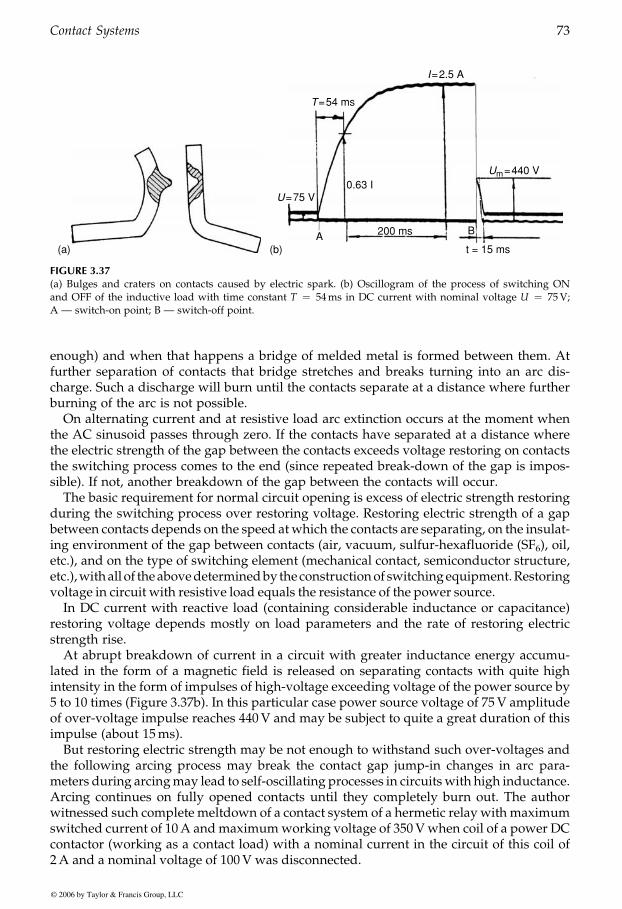
enough) and when that happens a bridge of melded metal is formed between them. Atfurther separation of contacts that bridge stretches and breaks turning into an arc dis-charge. Such a discharge will burn until the contacts separate at a distance where furtherburning of the arc is not possible.
On alternating current and at resistive load arc extinction occurs at the moment whenthe AC sinusoid passes through zero. If the contacts have separated at a distance wherethe electric strength of the gap between the contacts exceeds voltage restoring on contactsthe switching process comes to the end (since repeated break-down of the gap is impos-sible). If not, another breakdown of the gap between the contacts will occur.
The basic requirement for normal circuit opening is excess of electric strength restoringduring the switching process over restoring voltage. Restoring electric strength of a gapbetween contacts depends on the speed at which the contacts are separating, on the insulat-ing environment of the gap between contacts (air, vacuum, sulfur-hexafluoride (SF6), oil,etc.), and on the type of switching element (mechanical contact, semiconductor structure,etc.),withall of theabovedeterminedby theconstructionof switchingequipment.Restoringvoltage in circuit with resistive load equals the resistance of the power source.
In DC current with reactive load (containing considerable inductance or capacitance)restoring voltage depends mostly on load parameters and the rate of restoring electricstrength rise.
At abrupt breakdown of current in a circuit with greater inductance energy accumu-lated in the form of a magnetic field is released on separating contacts with quite highintensity in the form of impulses of high-voltage exceeding voltage of the power source by5 to 10 times (Figure 3.37b). In this particular case power source voltage of 75V amplitudeof over-voltage impulse reaches 440V and may be subject to quite a great duration of thisimpulse (about 15ms).
But restoring electric strength may be not enough to withstand such over-voltages andthe following arcing process may break the contact gap jump-in changes in arc para-meters during arcingmay lead to self-oscillating processes in circuits with high inductance.Arcing continues on fully opened contacts until they completely burn out. The authorwitnessed such complete meltdown of a contact system of a hermetic relay with maximumswitched current of 10A andmaximumworking voltage of 350Vwhen coil of a power DCcontactor (working as a contact load) with a nominal current in the circuit of this coil of2A and a nominal voltage of 100V was disconnected.
(a)A 200 ms
0.63 IU=75 V
T=54 ms
I=2.5 A
Um=440 V
t = 15 ms
B
(b)
FIGURE 3.37(a) Bulges and craters on contacts caused by electric spark. (b) Oscillogram of the process of switching ONand OFF of the inductive load with time constant T ¼ 54ms in DC current with nominal voltage U ¼ 75V;A — switch-on point; B — switch-off point.
GUREVICH / Electric Relays: Principles and Practises DK884X_c003 Final Proof page 73 29.10.2005 11:07pm
Contact Systems 73
© 2006 by Taylor & Francis Group, LLC
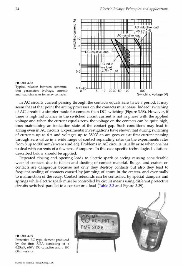
In AC circuits current passing through the contacts equals zero twice a period. It mayseem that at that point the arcing processes on the contacts must cease. Indeed, switchingof AC circuit is a simpler mode for contacts than DC switching (Figure 3.38). However, ifthere is high inductance in the switched circuit current is not in phase with the appliedvoltage and when the current equals zero, the voltage on the contacts can be quite high,thus maintaining an ionization state of the contact gap. Such conditions may lead toarcing even in AC circuits. Experimental investigations have shown that during switchingof currents up to 6A and voltages up to 380V an arc goes out at first current passingthrough zero value in a wide range of contact separating rates (in the experiments ratesfrom 8 up to 280mm/s were studied). Problems in AC circuits usually arise when one hasto deal with currents of a few tens of amperes. In this case specific technological solutionsdescribed below should be applied.
Repeated closing and opening leads to electric spark or arcing causing considerablewear of contacts due to fusion and dusting of contact material. Bulges and craters oncontacts are dangerous because not only they destroy contacts but also they lead tofrequent sealing of contacts caused by jamming of spurs in the craters, and eventuallyto malfunction of the relay. Contact rebounds can be controlled by special dampers andsprings while electric spark must be controlled by circuit means using different protective
FIGURE 3.38Typical relation between commuta-tion parameters (voltage, current)and load character for relay contacts.
DC resistive load
10
0.5
0.10 5 10 20 30 50 100 500
Switching voltage (V)
Sw
itchi
ng c
urre
nt (
A)
5
1 DC induc-
AC inductive load(cosf = 0.4)
tive load(L /R = 7 ms)
AC resistive load
FIGURE 3.39Protective RC type element producedby the firm RIFA consisting of a0.25mF, 630V DC capacitor and a 100Ohm resistor.
GUREVICH / Electric Relays: Principles and Practises DK884X_c003 Final Proof page 74 29.10.2005 11:07pm
74 Electric Relays: Principles and applications
© 2006 by Taylor & Francis Group, LLC
circuits switched parallel to a contact or a load (Table 3.3 and Figure 3.39).
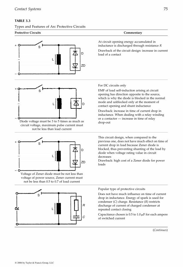
TABLE 3.3
Types and Features of Arc Protective Circuits
Protective Circuits Commentary
S+
–
– L
D
ZD
At circuit opening energy accumulated ininductance is discharged through resistance R
Drawback of the circuit design: increase in currentload of a contact
+
–
–
S
L D
Diode voltage must be 3 to 5 times as much ascircuit voltage, maximum pulse current must
not be less than load current
For DC circuits only
EMF of load self-induction arising at circuitopening has direction opposite to the source,which is why the diode is blocked in the normalmode and unblocked only at the moment ofcontact opening and shunt inductance
Drawback: increase in time of current drop ininductance. When dealing with a relay windingor a contactor — increase in time of relaydrop-out
S+
–
– L
D
ZD
Voltage of Zener diode must be not less thanvoltage of power source, Zener current mustnot be less than 0.5 to 0.7 of load current
This circuit design, when compared to theprevious one, does not have much effect on time ofcurrent drop in load because Zener diode isblocked, thus preventing shunting of the load bydiode when voltage rating value in circuitdecreasesDrawback: high cost of a Zener diode for powerloads
S
LR
C
Popular type of protective circuits
Does not have much influence on time of currentdrop in inductance. Energy of spark is used forcondenser (C) charge. Resistance (R) restrictsdischarge of current of charged condenser atrepeated contact closing
Capacitance chosen is 0.5 to 1.0mF for each ampereof switched current
(Continues)
GUREVICH / Electric Relays: Principles and Practises DK884X_c003 Final Proof page 75 29.10.2005 11:07pm
Contact Systems 75
© 2006 by Taylor & Francis Group, LLC
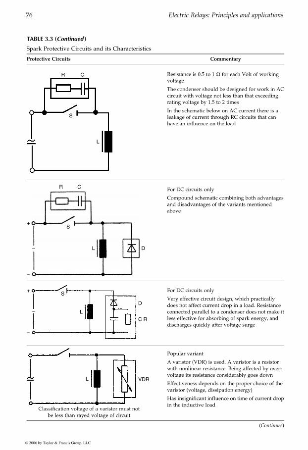
TABLE 3.3 (Continued )
Spark Protective Circuits and its Characteristics
Protective Circuits Commentary
L
S
R C Resistance is 0.5 to 1 V for each Volt of workingvoltage
The condenser should be designed for work in ACcircuit with voltage not less than that exceedingrating voltage by 1.5 to 2 times
In the schematic below on AC current there is aleakage of current through RC circuits that canhave an influence on the load
R
S
DL
+
–
–
C For DC circuits only
Compound schematic combining both advantagesand disadvantages of the variants mentionedabove
S
L
D
C R
+
–
–
For DC circuits only
Very effective circuit design, which practicallydoes not affect current drop in a load. Resistanceconnected parallel to a condenser does not make itless effective for absorbing of spark energy, anddischarges quickly after voltage surge
L VDR
Classification voltage of a varistor must notbe less than rayed voltage of circuit
Popular variant
A varistor (VDR) is used. A varistor is a resistorwith nonlinear resistance. Being affected by over-voltage its resistance considerably goes down
Effectiveness depends on the proper choice of thevaristor (voltage, dissipation energy)
Has insignificant influence on time of current dropin the inductive load
(Continues)
GUREVICH / Electric Relays: Principles and Practises DK884X_c003 Final Proof page 76 29.10.2005 11:07pm
76 Electric Relays: Principles and applications
© 2006 by Taylor & Francis Group, LLC
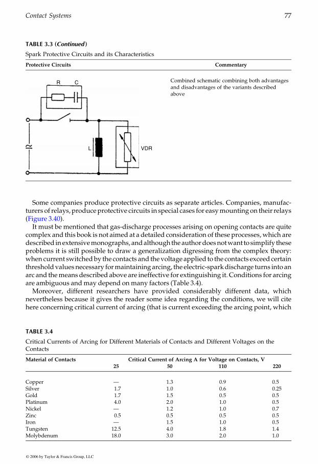
Some companies produce protective circuits as separate articles. Companies, manufac-turers of relays, produceprotective circuits in special cases for easymountingon their relays
It must be mentioned that gas-discharge processes arising on opening contacts are quitecomplex and this book is not aimed at a detailed consideration of these processes,which aredescribed inextensivemonographs, andalthough theauthordoesnotwant tosimplify theseproblems it is still possible to draw a generalization digressing from the complex theory:when current switchedby the contacts and thevoltage applied to the contacts exceed certainthresholdvalues necessary formaintaining arcing, the electric-sparkdischarge turns into anarc and themeansdescribed above are ineffective for extinguishing it. Conditions for arcingare ambiguous andmay depend onmany factors (Table 3.4).
Moreover, different researchers have provided considerably different data, whichnevertheless because it gives the reader some idea regarding the conditions, we will citehere concerning critical current of arcing (that is current exceeding the arcing point, which
TABLE 3.3 (Continued )
Spark Protective Circuits and its Characteristics
Protective Circuits Commentary
R
VDRL
C Combined schematic combining both advantagesand disadvantages of the variants describedabove
TABLE 3.4
Critical Currents of Arcing for Different Materials of Contacts and Different Voltages on theContacts
Material of Contacts Critical Current of Arcing A for Voltage on Contacts, V
25 50 110 220
Copper — 1.3 0.9 0.5Silver 1.7 1.0 0.6 0.25Gold 1.7 1.5 0.5 0.5Platinum 4.0 2.0 1.0 0.5Nickel — 1.2 1.0 0.7Zinc 0.5 0.5 0.5 0.5Iron — 1.5 1.0 0.5Tungsten 12.5 4.0 1.8 1.4Molybdenum 18.0 3.0 2.0 1.0
GUREVICH / Electric Relays: Principles and Practises DK884X_c003 Final Proof page 77 29.10.2005 11:07pm
Contact Systems 77
© 2006 by Taylor & Francis Group, LLC
(Figure 3.40).
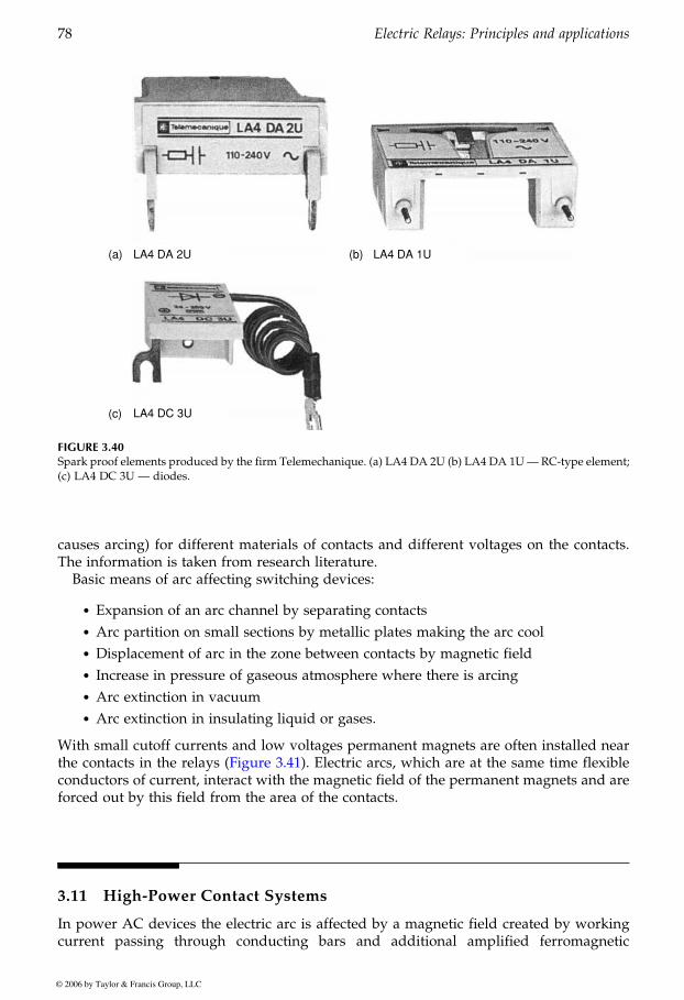
causes arcing) for different materials of contacts and different voltages on the contacts.The information is taken from research literature.
Basic means of arc affecting switching devices:
. Expansion of an arc channel by separating contacts
. Arc partition on small sections by metallic plates making the arc cool
. Displacement of arc in the zone between contacts by magnetic field
. Increase in pressure of gaseous atmosphere where there is arcing
. Arc extinction in vacuum
. Arc extinction in insulating liquid or gases.
With small cutoff currents and low voltages permanent magnets are often installed near
conductors of current, interact with the magnetic field of the permanent magnets and areforced out by this field from the area of the contacts.
3.11 High-Power Contact Systems
In power AC devices the electric arc is affected by a magnetic field created by workingcurrent passing through conducting bars and additional amplified ferromagnetic
(a) LA4 DA 2U
(c) LA4 DC 3U
(b) LA4 DA 1U
FIGURE 3.40Spark proof elements produced by the firm Telemechanique. (a) LA4 DA 2U (b) LA4 DA 1U— RC-type element;(c) LA4 DC 3U — diodes.
GUREVICH / Electric Relays: Principles and Practises DK884X_c003 Final Proof page 78 29.10.2005 11:07pm
78 Electric Relays: Principles and applications
© 2006 by Taylor & Francis Group, LLC
the contacts in the relays (Figure 3.41). Electric arcs, which are at the same time flexible
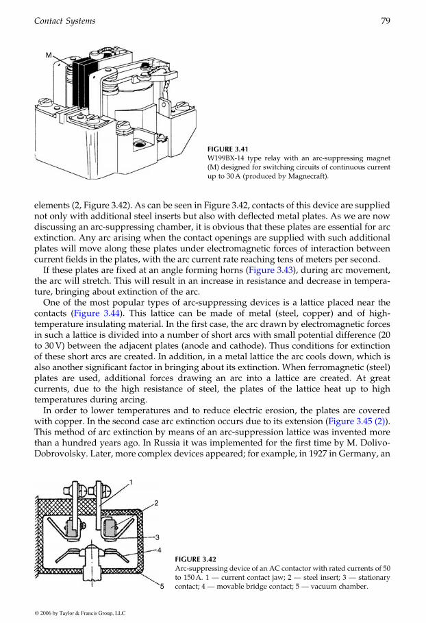
elements (2, Figure 3.42). As can be seen in Figure 3.42, contacts of this device are suppliednot only with additional steel inserts but also with deflected metal plates. As we are nowdiscussing an arc-suppressing chamber, it is obvious that these plates are essential for arcextinction. Any arc arising when the contact openings are supplied with such additionalplates will move along these plates under electromagnetic forces of interaction betweencurrent fields in the plates, with the arc current rate reaching tens of meters per second.
the arc will stretch. This will result in an increase in resistance and decrease in tempera-ture, bringing about extinction of the arc.
One of the most popular types of arc-suppressing devices is a lattice placed near the
temperature insulating material. In the first case, the arc drawn by electromagnetic forcesin such a lattice is divided into a number of short arcs with small potential difference (20to 30V) between the adjacent plates (anode and cathode). Thus conditions for extinctionof these short arcs are created. In addition, in a metal lattice the arc cools down, which isalso another significant factor in bringing about its extinction. When ferromagnetic (steel)plates are used, additional forces drawing an arc into a lattice are created. At greatcurrents, due to the high resistance of steel, the plates of the lattice heat up to hightemperatures during arcing.
In order to lower temperatures and to reduce electric erosion, the plates are covered
This method of arc extinction by means of an arc-suppression lattice was invented morethan a hundred years ago. In Russia it was implemented for the first time by M. Dolivo-Dobrovolsky. Later, more complex devices appeared; for example, in 1927 in Germany, an
M
FIGURE 3.41W199BX-14 type relay with an arc-suppressing magnet(M) designed for switching circuits of continuous currentup to 30A (produced by Magnecraft).
1
2
3
4
5
FIGURE 3.42Arc-suppressing device of an AC contactor with rated currents of 50to 150A. 1 — current contact jaw; 2 — steel insert; 3 — stationarycontact; 4 — movable bridge contact; 5 — vacuum chamber.
GUREVICH / Electric Relays: Principles and Practises DK884X_c003 Final Proof page 79 29.10.2005 11:07pm
Contact Systems 79
© 2006 by Taylor & Francis Group, LLC
If these plates are fixed at an angle forming horns (Figure 3.43), during arc movement,
contacts (Figure 3.44). This lattice can be made of metal (steel, copper) and of high-
with copper. In the second case arc extinction occurs due to its extension (Figure 3.45 (2)).
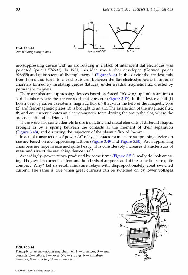
arc-suppressing device with an arc rotating in a stack of interjacent flat electrodes waspatented (patent 576932). In 1951, this idea was further developed (German patent
from horns and turns to a grid. Sub arcs between the flat electrodes rotate in annularchannels formed by insulating guides (lattices) under a radial magnetic flux, created bypermanent magnets.
There are also arc-suppressing devices based on forced ‘‘blowing up’’ of an arc into a
flown over by current creates a magnetic flux (F) that with the help of the magnetic core(2) and ferromagnetic plates (3) is brought to an arc. The interaction of the magnetic flux,F, and arc current creates an electromagnetic force driving the arc to the slot, where thearc cools off and is deionized.
There were also some attempts to use insulating and metal elements of different shapes,brought in by a spring between the contacts at the moment of their separation
In actual constructions of power AC relays (contactors) most arc-suppressing devices in
chambers are large in size and quite heavy. This considerably increases characteristics ofmass and size of the switching device itself.
ing. They switch currents of tens and hundreds of amperes and at the same time are quitecompact. Why? Let us recall miniature relays with disproportionately great switchedcurrent. The same is true when great currents can be switched on by lower voltages
FIGURE 3.43Arc moving along plates.
I I I I
i1 = i2 = const i1
< i2
uH
u0 u0
uH
i1i1
i2i2
FIGURE 3.44Principle of an arc-suppressing chamber. 1 — chamber; 3 — maincontacts; 2 — lattice; 4 — lever; 5,7, — springs; 6 — armature;8 — core; 9 — winding; 10 — wireways.
10
9
8
7
65
4
3
2
1
I
I
Arc
GUREVICH / Electric Relays: Principles and Practises DK884X_c003 Final Proof page 80 29.10.2005 11:07pm
80 Electric Relays: Principles and applications
© 2006 by Taylor & Francis Group, LLC
928655) and quite successfully implemented (Figure 3.46). In this device the arc descends
slot chamber where the arc cools off and goes out (Figure 3.47). In this device a coil (1)
(Figure 3.48), and distorting the trajectory of the plasmic flux of the arc.
Accordingly, power relays produced by some firms (Figure 3.51), really do look amaz-
use are based on arc-suppressing lattices (Figure 3.49 and Figure 3.50). Arc-suppressing
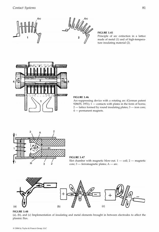
Arc Arc
1 2
FIGURE 3.45Principle of arc extinction in a latticemade of metal (1) and of high-tempera-ture insulating material (2).
1
3
2
4 4SN NS
FIGURE 3.46Arc-suppressing device with a rotating arc (German patent928655, 1951); 1 — contacts with plates in the form of horns;2 — lattice formed by round insulating plates; 3 — iron core;4 — permanent magnets.
3
1
3i
i
F
A 2
2
FIGURE 3.47Slot chamber with magnetic blow-out. 1 — coil; 2 — magneticcore; 3 — ferromagnetic plates; A — arc.
(a) (b) (c)
FIGURE 3.48(a), (b), and (c) Implementation of insulating and metal elements brought in between electrodes to affect theplasmic flux.
GUREVICH / Electric Relays: Principles and Practises DK884X_c003 Final Proof page 81 29.10.2005 11:07pm
Contact Systems 81
© 2006 by Taylor & Francis Group, LLC
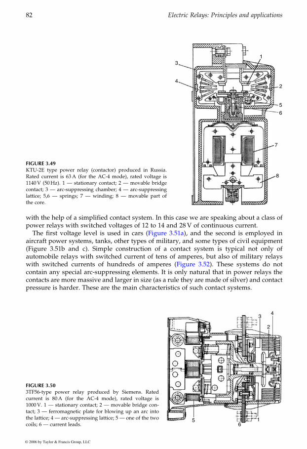
with the help of a simplified contact system. In this case we are speaking about a class ofpower relays with switched voltages of 12 to 14 and 28V of continuous current.
aircraft power systems, tanks, other types of military, and some types of civil equipment(Figure 3.51b and c). Simple construction of a contact system is typical not only ofautomobile relays with switched current of tens of amperes, but also of military relays
contain any special arc-suppressing elements. It is only natural that in power relays thecontacts are more massive and larger in size (as a rule they are made of silver) and contactpressure is harder. These are the main characteristics of such contact systems.
FIGURE 3.49KTU-2E type power relay (contactor) produced in Russia.Rated current is 63A (for the AC-4 mode), rated voltage is1140V (50Hz). 1 — stationary contact; 2 — movable bridgecontact; 3 — arc-suppressing chamber; 4 — arc-suppressinglattice; 5,6 — springs; 7 — winding; 8 — movable part ofthe core.
3
4
1
2
5
6
7
8
FIGURE 3.503TF56-type power relay produced by Siemens. Ratedcurrent is 80A (for the AC-4 mode), rated voltage is1000V. 1 — stationary contact; 2 — movable bridge con-tact; 3 — ferromagnetic plate for blowing up an arc intothe lattice; 4 — arc-suppressing lattice; 5 — one of the twocoils; 6 — current leads.
56
1
2
34
GUREVICH / Electric Relays: Principles and Practises DK884X_c003 Final Proof page 82 29.10.2005 11:07pm
82 Electric Relays: Principles and applications
© 2006 by Taylor & Francis Group, LLC
The first voltage level is used in cars (Figure 3.51a), and the second is employed in
with switched currents of hundreds of amperes (Figure 3.52). These systems do not
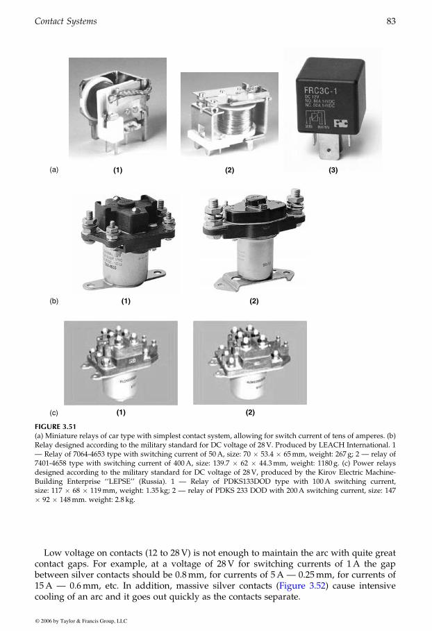
Low voltage on contacts (12 to 28V) is not enough to maintain the arc with quite greatcontact gaps. For example, at a voltage of 28V for switching currents of 1A the gapbetween silver contacts should be 0.8mm, for currents of 5A — 0.25mm, for currents of
cooling of an arc and it goes out quickly as the contacts separate.
(1) (2) (3)(a)
(b) (1) (2)
(1) (2)(c)
FIGURE 3.51(a) Miniature relays of car type with simplest contact system, allowing for switch current of tens of amperes. (b)Relay designed according to the military standard for DC voltage of 28V. Produced by LEACH International. 1— Relay of 7064-4653 type with switching current of 50A, size: 70 � 53.4 � 65mm, weight: 267 g; 2 — relay of7401-4658 type with switching current of 400A, size: 139.7 � 62 � 44.3mm, weight: 1180 g. (c) Power relaysdesigned according to the military standard for DC voltage of 28V, produced by the Kirov Electric Machine-Building Enterprise ‘‘LEPSE’’ (Russia). 1 — Relay of PDKS133DOD type with 100A switching current,size: 117 � 68 � 119mm, weight: 1.35 kg; 2 — relay of PDKS 233 DOD with 200A switching current, size: 147� 92 � 148mm. weight: 2.8 kg.
GUREVICH / Electric Relays: Principles and Practises DK884X_c003 Final Proof page 83 29.10.2005 11:07pm
Contact Systems 83
© 2006 by Taylor & Francis Group, LLC
15A — 0.6mm, etc. In addition, massive silver contacts (Figure 3.52) cause intensive
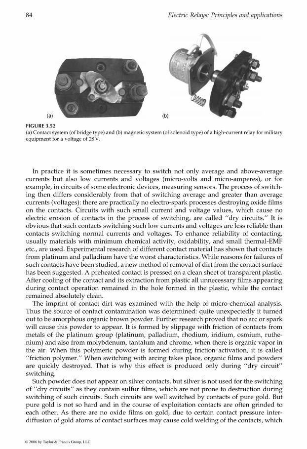
In practice it is sometimes necessary to switch not only average and above-averagecurrents but also low currents and voltages (micro-volts and micro-amperes), or forexample, in circuits of some electronic devices, measuring sensors. The process of switch-ing then differs considerably from that of switching average and greater than averagecurrents (voltages): there are practically no electro-spark processes destroying oxide filmson the contacts. Circuits with such small current and voltage values, which cause noelectric erosion of contacts in the process of switching, are called ‘‘dry circuits.’’ It isobvious that such contacts switching such low currents and voltages are less reliable thancontacts switching normal currents and voltages. To enhance reliability of contacting,usually materials with minimum chemical activity, oxidability, and small thermal-EMFetc., are used. Experimental research of different contact material has shown that contactsfrom platinum and palladium have the worst characteristics. While reasons for failures ofsuch contacts have been studied, a newmethod of removal of dirt from the contact surfacehas been suggested. A preheated contact is pressed on a clean sheet of transparent plastic.After cooling of the contact and its extraction from plastic all unnecessary films appearingduring contact operation remained in the hole formed in the plastic, while the contactremained absolutely clean.
The imprint of contact dirt was examined with the help of micro-chemical analysis.Thus the source of contact contamination was determined: quite unexpectedly it turnedout to be amorphous organic brown powder. Further research proved that no arc or sparkwill cause this powder to appear. It is formed by slippage with friction of contacts frommetals of the platinum group (platinum, palladium, rhodium, iridium, osmium, ruthe-nium) and also from molybdenum, tantalum and chrome, when there is organic vapor inthe air. When this polymeric powder is formed during friction activation, it is called‘‘friction polymer.’’ When switching with arcing takes place, organic films and powdersare quickly destroyed. That is why this effect is produced only during ‘‘dry circuit’’switching.
Such powder does not appear on silver contacts, but silver is not used for the switchingof ‘‘dry circuits’’ as they contain sulfur films, which are not prone to destruction duringswitching of such circuits. Such circuits are well switched by contacts of pure gold. Butpure gold is not so hard and in the course of exploitation contacts are often grinded toeach other. As there are no oxide films on gold, due to certain contact pressure inter-diffusion of gold atoms of contact surfaces may cause cold welding of the contacts, which
(a) (b)
FIGURE 3.52(a) Contact system (of bridge type) and (b) magnetic system (of solenoid type) of a high-current relay for militaryequipment for a voltage of 28V.
GUREVICH / Electric Relays: Principles and Practises DK884X_c003 Final Proof page 84 29.10.2005 11:08pm
84 Electric Relays: Principles and applications
© 2006 by Taylor & Francis Group, LLC
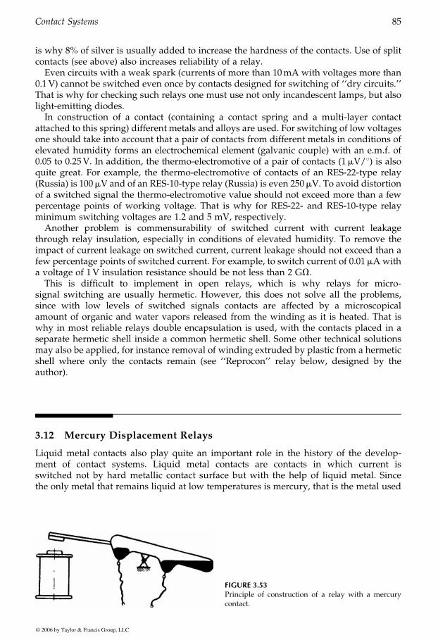
is why 8% of silver is usually added to increase the hardness of the contacts. Use of splitcontacts (see above) also increases reliability of a relay.
Even circuits with a weak spark (currents of more than 10mA with voltages more than0.1V) cannot be switched even once by contacts designed for switching of ‘‘dry circuits.’’That is why for checking such relays one must use not only incandescent lamps, but alsolight-emitting diodes.
In construction of a contact (containing a contact spring and a multi-layer contactattached to this spring) different metals and alloys are used. For switching of low voltagesone should take into account that a pair of contacts from different metals in conditions ofelevated humidity forms an electrochemical element (galvanic couple) with an e.m.f. of0.05 to 0.25V. In addition, the thermo-electromotive of a pair of contacts (1mV/8) is alsoquite great. For example, the thermo-electromotive of contacts of an RES-22-type relay(Russia) is 100mV and of an RES-10-type relay (Russia) is even 250mV. To avoid distortionof a switched signal the thermo-electromotive value should not exceed more than a fewpercentage points of working voltage. That is why for RES-22- and RES-10-type relayminimum switching voltages are 1.2 and 5 mV, respectively.
Another problem is commensurability of switched current with current leakagethrough relay insulation, especially in conditions of elevated humidity. To remove theimpact of current leakage on switched current, current leakage should not exceed than afew percentage points of switched current. For example, to switch current of 0.01mA witha voltage of 1V insulation resistance should be not less than 2 GV.
This is difficult to implement in open relays, which is why relays for micro-signal switching are usually hermetic. However, this does not solve all the problems,since with low levels of switched signals contacts are affected by a microscopicalamount of organic and water vapors released from the winding as it is heated. That iswhy in most reliable relays double encapsulation is used, with the contacts placed in aseparate hermetic shell inside a common hermetic shell. Some other technical solutionsmay also be applied, for instance removal of winding extruded by plastic from a hermeticshell where only the contacts remain (see ‘‘Reprocon’’ relay below, designed by theauthor).
3.12 Mercury Displacement Relays
Liquid metal contacts also play quite an important role in the history of the develop-ment of contact systems. Liquid metal contacts are contacts in which current isswitched not by hard metallic contact surface but with the help of liquid metal. Sincethe only metal that remains liquid at low temperatures is mercury, that is the metal used
FIGURE 3.53Principle of construction of a relay with a mercurycontact.
GUREVICH / Electric Relays: Principles and Practises DK884X_c003 Final Proof page 85 29.10.2005 11:08pm
Contact Systems 85
© 2006 by Taylor & Francis Group, LLC
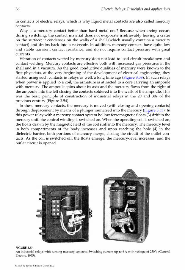
in contacts of electric relays, which is why liquid metal contacts are also called mercurycontacts.
Why is a mercury contact better than hard metal one? Because when arcing occursduring switching, the contact material does not evaporate irretrievably leaving a crateron the surface; it condenses on the walls of a shell (which usually contains a mercurycontact) and drains back into a reservoir. In addition, mercury contacts have quite lowand stable transient contact resistance, and do not require contact pressure with greatcurrents.
Vibration of contacts wetted by mercury does not lead to load circuit breakdown andcontact welding. Mercury contacts are effective both with increased gas pressures in theshell and in a vacuum. As the good conductive qualities of mercury were known to thefirst physicists, at the very beginning of the development of electrical engineering, they
when power is applied to a coil, the armature is attracted to a core carrying an ampoulewith mercury. The ampoule spins about its axis and the mercury flows from the right ofthe ampoule into the left closing the contacts soldered into the walls of the ampoule. Thiswas the basic principle of construction of industrial relays in the 20 and 30s of theprevious century (Figure 3.54).
In these mercury contacts, the mercury is moved (with closing and opening contacts)
this power relay with a mercury contact system hollow ferromagnetic floats (3) drift in themercury until the control winding is switched on. When the operating coil is switched on,the floats drawn by the magnetic field of the coil sink into the mercury. The mercury levelin both compartments of the body increases and upon reaching the hole (4) in thedielectric barrier, both portions of mercury merge, closing the circuit of the outlet con-tacts. As the coil is switched off, the floats emerge, the mercury-level increases, and theoutlet circuit is opened.
FIGURE 3.54An industrial relays with turning mercury contacts. Switching current up to 6A with voltage of 250V (GeneralElectric, 1935).
GUREVICH / Electric Relays: Principles and Practises DK884X_c003 Final Proof page 86 29.10.2005 11:08pm
86 Electric Relays: Principles and applications
© 2006 by Taylor & Francis Group, LLC
started using such contacts in relays as well, a long time ago (Figure 3.53). In such relays
through displacement by means of a plunger immersed into the mercury (Figure 3.55). In
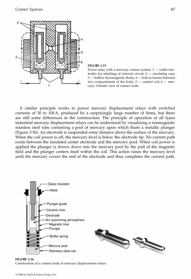
A similar principle works in power mercury displacement relays with switchedcurrents of 30 to 100A, produced by a surprisingly large number of firms, but thereare still some differences in the construction. The principle of operation of all typesindustrial mercury displacement relays can be understood by visualizing a nonmagneticstainless steel tube containing a pool of mercury upon which floats a metallic plunger(Figure 3.56). An electrode is suspended some distance above the surface of the mercury.When the coil power is off, the mercury level is below the electrode tip. No current pathexists between the insulated center electrode and the mercury pool. When coil power isapplied the plunger is drawn down into the mercury pool by the pull of the magneticfield and the plunger centers itself within the coil. This action raises the mercury leveluntil the mercury covers the end of the electrode and thus completes the current path.
3
2
4
5
6
1ii
FIGURE 3.55Power relay with a mercury contact system. 1 — outlet elec-trodes for attaching of external circuit; 2 — insulating case;3 — hollow ferromagnetic floats; 4 — hole in barrier betweentwo compartments of the body; 5 — control coil; 6 — mer-cury. Outside view of contact node.
Glass insulator
Plunger guide
Ceramic liner
ElectrodeArc quenching atmosphere
Magnetic linerPlunger
Buffer spring
Mercury pool
Stainless steel can
Weld
FIGURE 3.56Construction of a contact node of mercury displacement relays.
GUREVICH / Electric Relays: Principles and Practises DK884X_c003 Final Proof page 87 29.10.2005 11:08pm
Contact Systems 87
© 2006 by Taylor & Francis Group, LLC
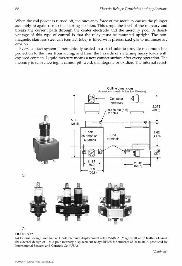
When the coil power is turned off, the buoyancy force of the mercury causes the plungerassembly to again rise to the starting position. This drops the level of the mercury andbreaks the current path through the center electrode and the mercury pool. A disad-vantage of this type of control is that the relay must be mounted upright. The non-magnetic stainless steel can (contact tube) is filled with pressurized gas to minimize arcerosion.
Every contact system is hermetically sealed in a steel tube to provide maximum life,protection to the user from arcing, and from the hazards of switching heavy loads withexposed contacts. Liquid mercury means a new contact surface after every operation. Themercury is self-renewing; it cannot pit, weld, disintegrate or oxidize. The internal resist-
Contactor
Coil1 pole
35 amps or60 amps
terminals
terminals
0.180 dia (4.6)2.375(60.3)
1.62(41.3)
5.06(128.5)
1.187(30.2)
2.0(50.8)
2.312(58.7)
1.05(27)
2 holes
Outline dimensionsdimensions shown in inches & (millimeters).
(a)
(b)
FIGURE 3.57(a) External design and size of 1 pole mercury displacement relay WM60A (Magnecraft and Struthers-Dunn);(b) external design of 1 to 3 pole mercury displacement relays BFL35 for currents of 30 to 100A produced byInternational Sensors and Controls Co. (USA).
(Continues)
GUREVICH / Electric Relays: Principles and Practises DK884X_c003 Final Proof page 88 29.10.2005 11:08pm
88 Electric Relays: Principles and applications
© 2006 by Taylor & Francis Group, LLC
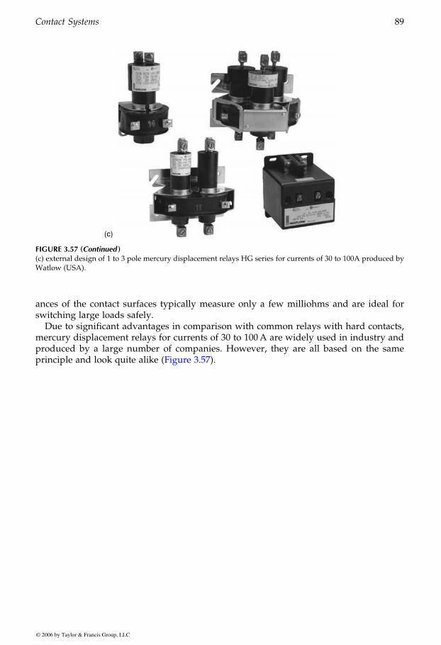
ances of the contact surfaces typically measure only a few milliohms and are ideal forswitching large loads safely.
Due to significant advantages in comparison with common relays with hard contacts,mercury displacement relays for currents of 30 to 100A are widely used in industry andproduced by a large number of companies. However, they are all based on the same
(c)
FIGURE 3.57 (Continued )(c) external design of 1 to 3 pole mercury displacement relays HG series for currents of 30 to 100A produced byWatlow (USA).
GUREVICH / Electric Relays: Principles and Practises DK884X_c003 Final Proof page 89 29.10.2005 11:08pm
Contact Systems 89
© 2006 by Taylor & Francis Group, LLC
principle and look quite alike (Figure 3.57).
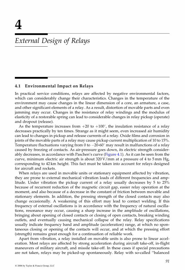
4External Design of Relays
4.1 Environmental Impact on Relays
In practical service conditions, relays are affected by negative environmental factors,which can considerably change their characteristics. Changes in the temperature of theenvironment may cause changes in the linear dimension of a core, an armature, a case,and other significant elements of a relay. As a result, distortion of movable parts and evenjamming may occur. Changes in the resistance of relay windings and the modulus ofelasticity of a restorable spring can lead to considerable changes in relay pickup (operate)and dropout (release).
As the temperature increases from þ20 to þ1008, the insulation resistance of a relaydecreases practically by ten times. Strange as it might seem, even increased air humiditycan lead to changes in pickup and release currents of a relay. Oxide films and corrosion injoints of the movable parts of a relay may cause pickup current multiplication of 10 to 15%.Temperature fluctuations varying from 0 to �20-608 may result in malfunctions of a relaycaused by freezing of contacts. As air-pressure goes down, its electric strength consider-
curve, minimum electric air strength is about 320V/mm at a pressure of 4 to 5mm Hg,corresponding to 42 km height. This fact must be taken into account for relays designedfor aircraft and rockets.
When relays are used in movable units or stationary equipment affected by vibration,they are prone to external mechanical vibration loads of different frequencies and amp-litude. Under vibration the pickup current of a relay usually decreases by 5 to 25%because of recurrent reduction of the magnetic circuit gap, easier relay operation at themoment, and also because of a decrease in the constant of friction between movable andstationary elements. In addition, the pressing strength of the closed contacts may alsochange occasionally. A weakening of this effort may lead to contact welding. If thisfrequency of external oscillations is in accordance with the frequency of natural oscilla-tions, resonance may occur, causing a sharp increase in the amplitude of oscillations,bringing about opening of closed contacts or closing of open contacts, breaking windingoutlets, and eventually causing mechanical collapse of the relay. Relay specificationsusually indicate frequency band and amplitude (acceleration) range, at which no spon-taneous closing or opening of the contacts will occur, and at which the pressing effort(strength) remains great enough for a continuation of reliable work.
Apart from vibration, a relay installed on movable units is also prone to linear accel-eration. Most relays are affected by strong acceleration during aircraft take-off, in-flightmaneuvers of military aircraft, and missile take-off. In these cases if special precautionsare not taken, relays may be picked-up spontaneously. Relay with so-called ‘‘balanced
GUREVICH / Electric Relays: Principles and Practises DK884X_c004 Final Proof page 91 29.10.2005 11:15pm
91© 2006 by Taylor & Francis Group, LLC
ably decreases, in accordance with Paschen’s curve (Figure 4.1). As it can be seen from the
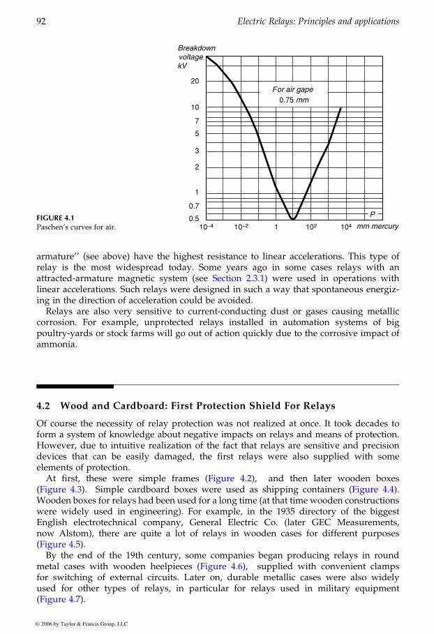
armature’’ (see above) have the highest resistance to linear accelerations. This type ofrelay is the most widespread today. Some years ago in some cases relays with an
linear accelerations. Such relays were designed in such a way that spontaneous energiz-ing in the direction of acceleration could be avoided.
Relays are also very sensitive to current-conducting dust or gases causing metalliccorrosion. For example, unprotected relays installed in automation systems of bigpoultry-yards or stock farms will go out of action quickly due to the corrosive impact ofammonia.
4.2 Wood and Cardboard: First Protection Shield For Relays
Of course the necessity of relay protection was not realized at once. It took decades toform a system of knowledge about negative impacts on relays and means of protection.However, due to intuitive realization of the fact that relays are sensitive and precisiondevices that can be easily damaged, the first relays were also supplied with someelements of protection.
At first, these were simple frames and then later wooden boxes
Wooden boxes for relays had been used for a long time (at that time wooden constructionswere widely used in engineering). For example, in the 1935 directory of the biggestEnglish electrotechnical company, General Electric Co. (later GEC Measurements,now Alstom), there are quite a lot of relays in wooden cases for different purposes
By the end of the 19th century, some companies began producing relays in roundmetal cases with wooden heelpieces supplied with convenient clampsfor switching of external circuits. Later on, durable metallic cases were also widelyused for other types of relays, in particular for used in military equipment
FIGURE 4.1Paschen’s curves for air.
v
F0.75
0.5
0.7
1
2
3
5
7
10
20
10−4 10−2 102 1041
GUREVICH / Electric Relays: Principles and Practises DK884X_c004 Final Proof page 92 29.10.2005 11:15pm
92 Electric Relays: Principles and applications
© 2006 by Taylor & Francis Group, LLC
(Figure 4.2),(Figure 4.3). Simple cardboard boxes were used as shipping containers (Figure 4.4).
(Figure 4.5).
(Figure 4.7).
(Figure
relays
4.6),
attracted-armature magnetic system (see Section 2.3.1) were used in operations with
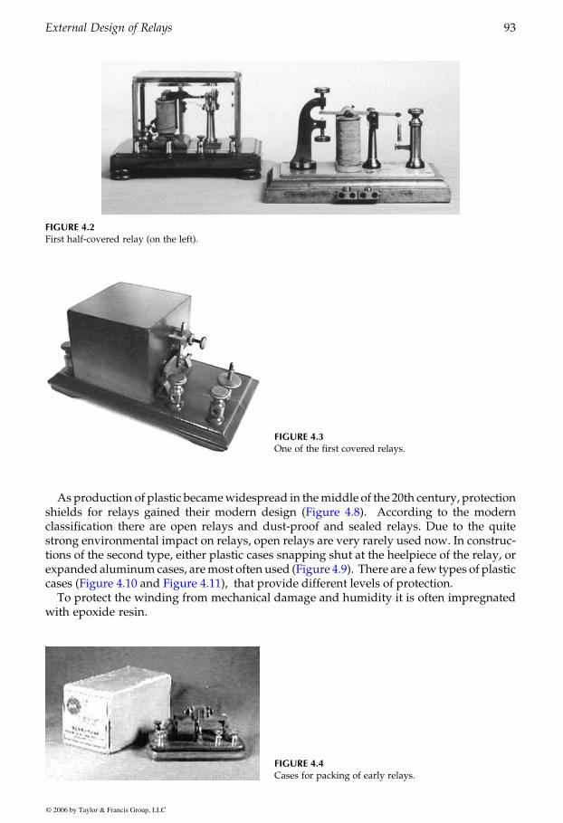
Asproduction of plastic becamewidespread in themiddle of the 20th century, protectionAccording to the modern
classification there are open relays and dust-proof and sealed relays. Due to the quitestrong environmental impact on relays, open relays are very rarely used now. In construc-tions of the second type, either plastic cases snapping shut at the heelpiece of the relay, or
To protect the winding from mechanical damage and humidity it is often impregnated
FIGURE 4.2First half-covered relay (on the left).
FIGURE 4.3One of the first covered relays.
FIGURE 4.4Cases for packing of early relays.
GUREVICH / Electric Relays: Principles and Practises DK884X_c004 Final Proof page 93 29.10.2005 11:15pm
External Design of Relays 93
© 2006 by Taylor & Francis Group, LLC
shields for relays gained their modern design (Figure 4.8).
expanded aluminum cases, aremost often used (Figure 4.9). There are a few types of plastic
with epoxide resin.
cases (Figure 4.10 and Figure 4.11), that provide different levels of protection.
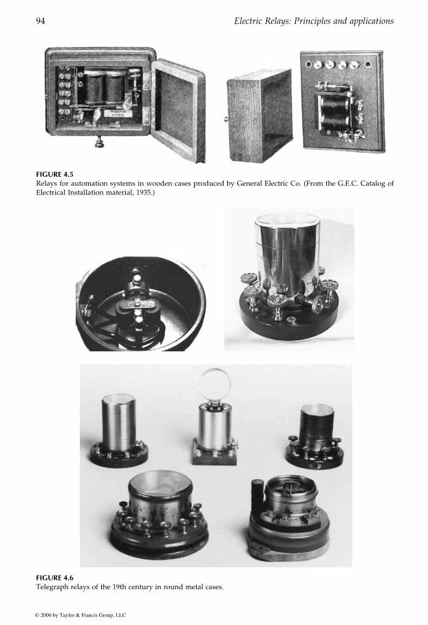
FIGURE 4.5Relays for automation systems in wooden cases produced by General Electric Co. (From the G.E.C. Catalog ofElectrical Installation material, 1935.)
FIGURE 4.6Telegraph relays of the 19th century in round metal cases.
GUREVICH / Electric Relays: Principles and Practises DK884X_c004 Final Proof page 94 29.10.2005 11:15pm
94 Electric Relays: Principles and applications
© 2006 by Taylor & Francis Group, LLC
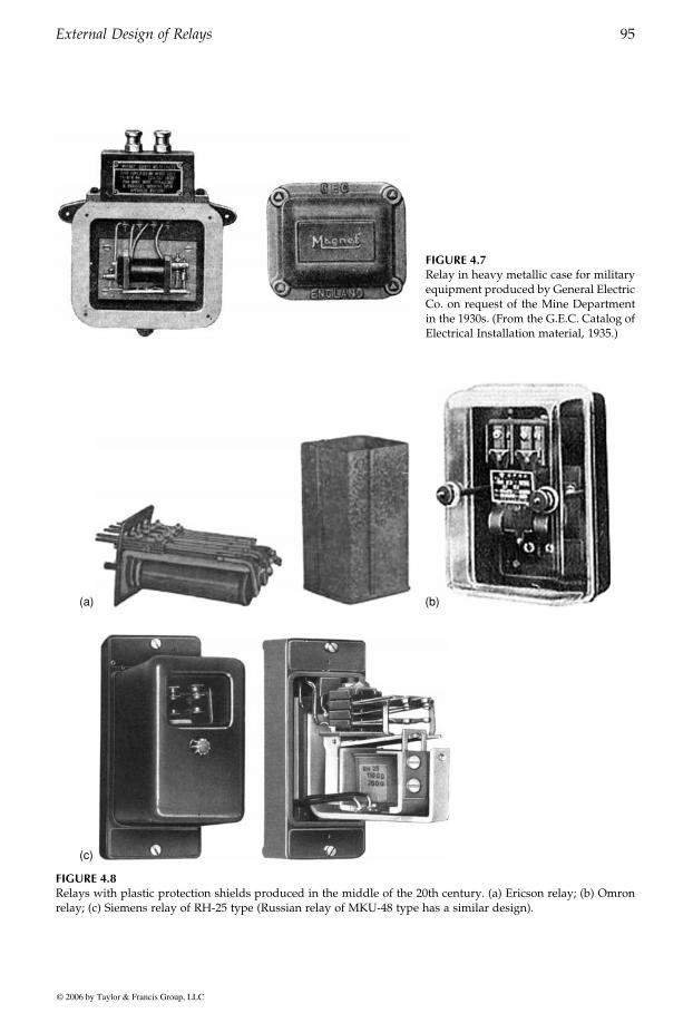
FIGURE 4.7Relay in heavy metallic case for militaryequipment produced by General ElectricCo. on request of the Mine Departmentin the 1930s. (From the G.E.C. Catalog ofElectrical Installation material, 1935.)
(a)
(c)
(b)
FIGURE 4.8Relays with plastic protection shields produced in the middle of the 20th century. (a) Ericson relay; (b) Omronrelay; (c) Siemens relay of RH-25 type (Russian relay of MKU-48 type has a similar design).
GUREVICH / Electric Relays: Principles and Practises DK884X_c004 Final Proof page 95 29.10.2005 11:15pm
External Design of Relays 95
© 2006 by Taylor & Francis Group, LLC
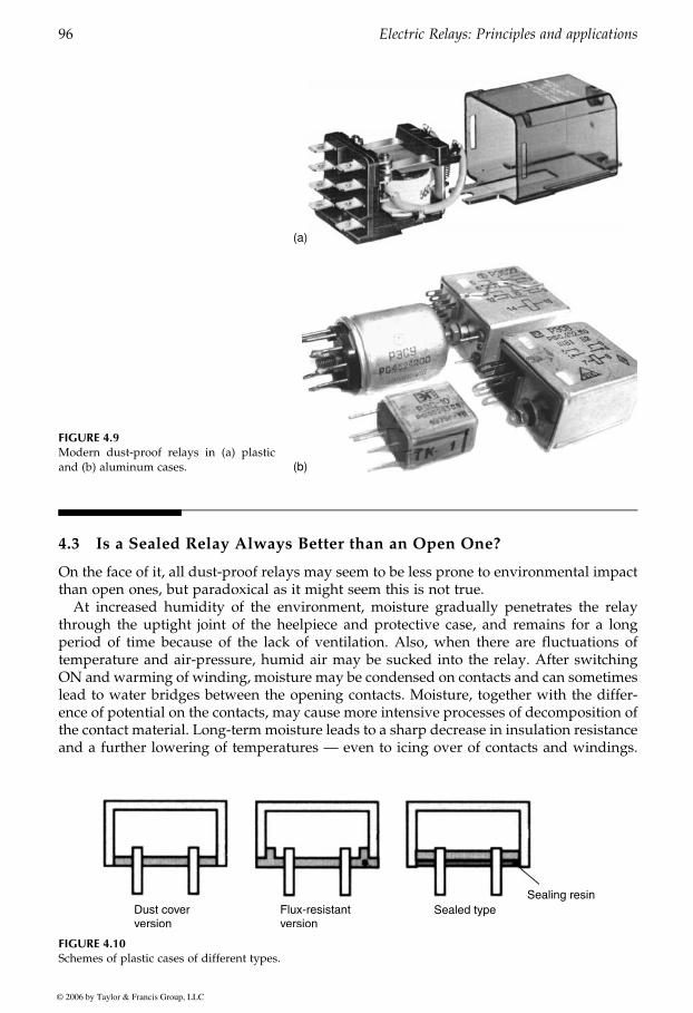
4.3 Is a Sealed Relay Always Better than an Open One?
On the face of it, all dust-proof relays may seem to be less prone to environmental impactthan open ones, but paradoxical as it might seem this is not true.
At increased humidity of the environment, moisture gradually penetrates the relaythrough the uptight joint of the heelpiece and protective case, and remains for a longperiod of time because of the lack of ventilation. Also, when there are fluctuations oftemperature and air-pressure, humid air may be sucked into the relay. After switchingON and warming of winding, moisture may be condensed on contacts and can sometimeslead to water bridges between the opening contacts. Moisture, together with the differ-ence of potential on the contacts, may cause more intensive processes of decomposition ofthe contact material. Long-term moisture leads to a sharp decrease in insulation resistanceand a further lowering of temperatures — even to icing over of contacts and windings.
FIGURE 4.9Modern dust-proof relays in (a) plasticand (b) aluminum cases.
(a)
(b)
FIGURE 4.10Schemes of plastic cases of different types.
GUREVICH / Electric Relays: Principles and Practises DK884X_c004 Final Proof page 96 29.10.2005 11:15pm
96 Electric Relays: Principles and applications
© 2006 by Taylor & Francis Group, LLC
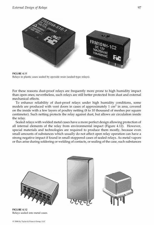
For these reasons dust-proof relays are frequently more prone to high humidity impactthan open ones; nevertheless, such relays are still better protected from dust and externalmechanical effects.
To enhance reliability of dust-proof relays under high humidity conditions, somemodels are produced with vent doors in cases of approximately 1 cm2 in area, coveredon the inside with a few layers of poultry netting (8 to 10 thousand of meshes per squarecentimeter). Such netting protects the relay against dust, but allows air circulation insidethe relay.
Sealed relays with weldedmetal cases have amore perfect design allowing protection ofall internal elements of the relay from environmental impact (Figure 4.12). However,special materials and technologies are required to produce them mostly, because evensmall amounts of substances which usually do not affect open relay operation can have astrong negative impact if found in small stoppered cases of sealed relays. As metal vaporsor flux arise during soldering or welding of contacts, or sealing of the case, such substances
FIGURE 4.11Relays in plastic cases sealed by epoxide resin (sealed-type relays).
FIGURE 4.12Relays sealed into metal cases.
GUREVICH / Electric Relays: Principles and Practises DK884X_c004 Final Proof page 97 29.10.2005 11:15pm
External Design of Relays 97
© 2006 by Taylor & Francis Group, LLC
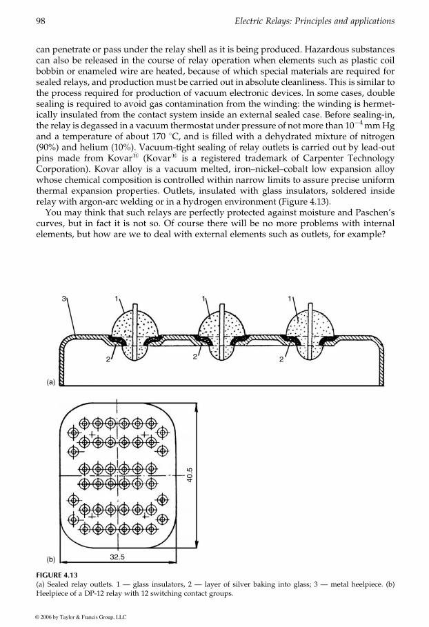
can penetrate or pass under the relay shell as it is being produced. Hazardous substancescan also be released in the course of relay operation when elements such as plastic coilbobbin or enameled wire are heated, because of which special materials are required forsealed relays, and production must be carried out in absolute cleanliness. This is similar tothe process required for production of vacuum electronic devices. In some cases, doublesealing is required to avoid gas contamination from the winding: the winding is hermet-ically insulated from the contact system inside an external sealed case. Before sealing-in,the relay is degassed in a vacuum thermostat under pressure of not more than 10�4mmHgand a temperature of about 170 8C, and is filled with a dehydrated mixture of nitrogen(90%) and helium (10%). Vacuum-tight sealing of relay outlets is carried out by lead-outpins made from Kovar1 (Kovar1 is a registered trademark of Carpenter TechnologyCorporation). Kovar alloy is a vacuum melted, iron–nickel–cobalt low expansion alloywhose chemical composition is controlled within narrow limits to assure precise uniformthermal expansion properties. Outlets, insulated with glass insulators, soldered insiderelay with argon-arc welding or in a hydrogen environment (Figure 4.13).
You may think that such relays are perfectly protected against moisture and Paschen’scurves, but in fact it is not so. Of course there will be no more problems with internalelements, but how are we to deal with external elements such as outlets, for example?
(a)
(b)
FIGURE 4.13(a) Sealed relay outlets. 1 — glass insulators, 2 — layer of silver baking into glass; 3 — metal heelpiece. (b)Heelpiece of a DP-12 relay with 12 switching contact groups.
GUREVICH / Electric Relays: Principles and Practises DK884X_c004 Final Proof page 98 29.10.2005 11:15pm
98 Electric Relays: Principles and applications
© 2006 by Taylor & Francis Group, LLC
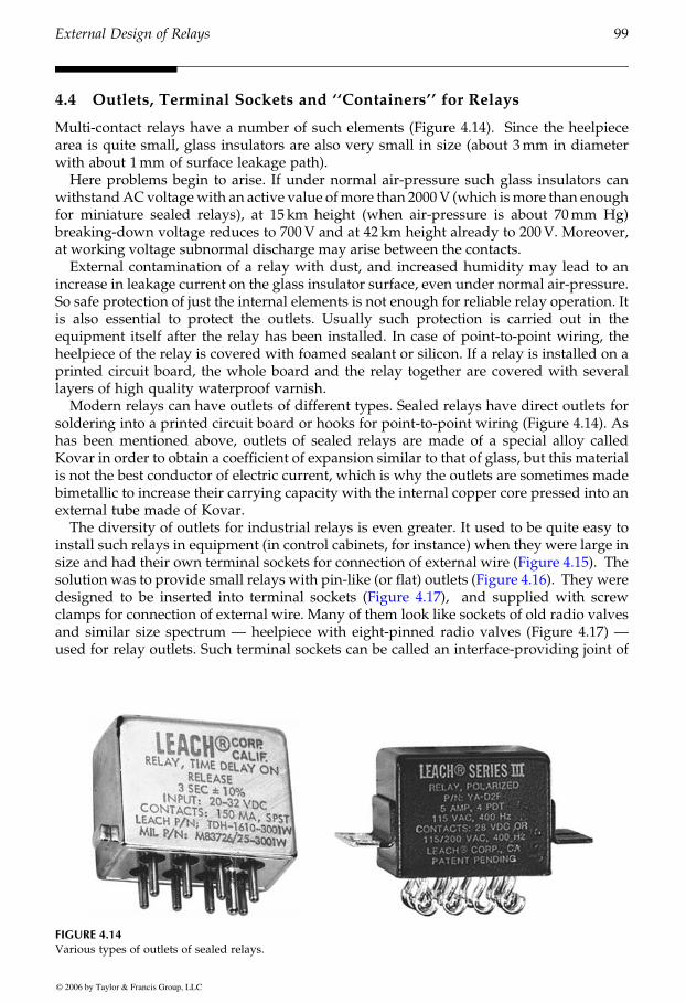
4.4 Outlets, Terminal Sockets and ‘‘Containers’’ for Relays
Multi-contact relays have a number of such elements (Figure 4.14). Since the heelpiecearea is quite small, glass insulators are also very small in size (about 3mm in diameterwith about 1mm of surface leakage path).
Here problems begin to arise. If under normal air-pressure such glass insulators canwithstandACvoltagewith an active value ofmore than 2000V (which ismore than enoughfor miniature sealed relays), at 15 km height (when air-pressure is about 70mm Hg)breaking-down voltage reduces to 700V and at 42 km height already to 200V. Moreover,at working voltage subnormal discharge may arise between the contacts.
External contamination of a relay with dust, and increased humidity may lead to anincrease in leakage current on the glass insulator surface, even under normal air-pressure.So safe protection of just the internal elements is not enough for reliable relay operation. Itis also essential to protect the outlets. Usually such protection is carried out in theequipment itself after the relay has been installed. In case of point-to-point wiring, theheelpiece of the relay is covered with foamed sealant or silicon. If a relay is installed on aprinted circuit board, the whole board and the relay together are covered with severallayers of high quality waterproof varnish.
Modern relays can have outlets of different types. Sealed relays have direct outlets forsoldering into a printed circuit board or hooks for point-to-point wiring (Figure 4.14). Ashas been mentioned above, outlets of sealed relays are made of a special alloy calledKovar in order to obtain a coefficient of expansion similar to that of glass, but this materialis not the best conductor of electric current, which is why the outlets are sometimes madebimetallic to increase their carrying capacity with the internal copper core pressed into anexternal tube made of Kovar.
The diversity of outlets for industrial relays is even greater. It used to be quite easy toinstall such relays in equipment (in control cabinets, for instance) when they were large in
The
and supplied with screwclamps for connection of external wire. Many of them look like sockets of old radio valvesand similar size spectrum — heelpiece with eight-pinned radio valves (Figure 4.17) —
FIGURE 4.14Various types of outlets of sealed relays.
GUREVICH / Electric Relays: Principles and Practises DK884X_c004 Final Proof page 99 29.10.2005 11:15pm
External Design of Relays 99
© 2006 by Taylor & Francis Group, LLC
size and had their own terminal sockets for connection of external wire (Figure 4.15).
used for relay outlets. Such terminal sockets can be called an interface-providing joint of
designed to be inserted into terminal sockets (Figure 4.17),solution was to provide small relays with pin-like (or flat) outlets (Figure 4.16). They were
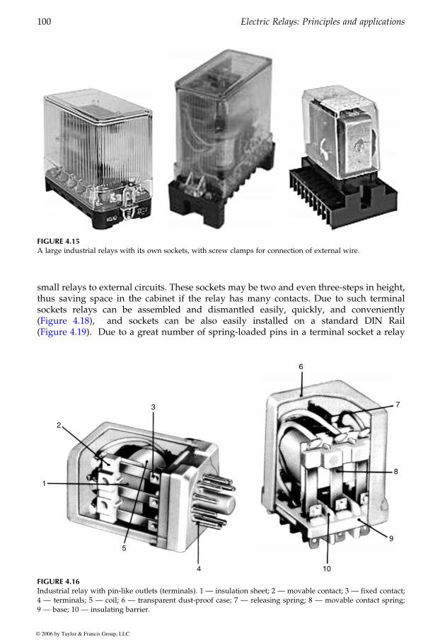
small relays to external circuits. These sockets may be two and even three-steps in height,thus saving space in the cabinet if the relay has many contacts. Due to such terminalsockets relays can be assembled and dismantled easily, quickly, and conveniently
and sockets can be also easily installed on a standard DIN RailDue to a great number of spring-loaded pins in a terminal socket a relay
FIGURE 4.15A large industrial relays with its own sockets, with screw clamps for connection of external wire.
FIGURE 4.16Industrial relay with pin-like outlets (terminals). 1 — insulation sheet; 2 — movable contact; 3 — fixed contact;4 — terminals; 5 — coil; 6 — transparent dust-proof case; 7 — releasing spring; 8 — movable contact spring;9 — base; 10 — insulating barrier.
GUREVICH / Electric Relays: Principles and Practises DK884X_c004 Final Proof page 100 29.10.2005 11:15pm
100 Electric Relays: Principles and applications
© 2006 by Taylor & Francis Group, LLC
(Figure 4.18),(Figure 4.19).
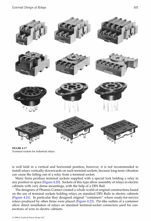
is well held in a vertical and horizontal position, however, it is not recommended toinstall relays vertically downwards on such terminal sockets, because long-term vibrationcan cause the falling out of a relay from a terminal socket.
Many firms produce terminal sockets supplied with a special lock holding a relay in
cabinets with very dense mountings, with the help of a DIN Rail.The designers of Phoenix Contact created a whole world of original constructions based
on the use of terminal sockets holding relays on standard DIN Rails in electric cabinetsIn particular they designed original ‘‘containers’’ where ready-for-service
Pin-like outlets of a containerallow direct installation of relays on standard terminal-socket connectors used for con-nections of wire in electric cabinets.
FIGURE 4.17Terminal sockets for industrial relays.
GUREVICH / Electric Relays: Principles and Practises DK884X_c004 Final Proof page 101 29.10.2005 11:15pm
External Design of Relays 101
© 2006 by Taylor & Francis Group, LLC
any position in space (Figure 4.20). Sockets of this type allow assembly of relays in electric
(Figure 4.21).relays produced by other firms were placed (Figure 4.22).
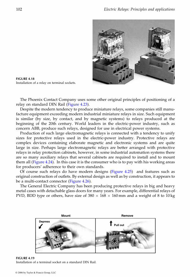
The Phoenix Contact Company uses some other original principles of positioning of a
Despite the modern tendency to produce miniature relays, some companies still manu-facture equipment exceeding modern industrial miniature relays in size. Such equipmentis similar (by size, by contact, and by magnetic systems) to relays produced at thebeginning of the 20th century. World leaders in the electric-power industry, such asconcern ABB, produce such relays, designed for use in electrical power systems.
Production of such large electromagnetic relays is connected with a tendency to unifysizes for protective relays used in the electric-power industry. Protective relays arecomplex devices containing elaborate magnetic and electronic systems and are quitelarge in size. Perhaps large electromagnetic relays are better arranged with protectiverelays in relay protection cabinets, however, in some industrial automation systems thereare so many auxiliary relays that several cabinets are required to install and to mount
for producers’ adherence to their own standards.and features such as
original construction of outlets. By external design as well as by construction, it appears to
The General Electric Company has been producing protective relays in big and heavymetal cases with detachable glass doors for many years. For example, differential relays ofPVD, BDD type or others, have size of 380 � 168 � 160mm and a weight of 8 to 10 kg
FIGURE 4.18Installation of a relay on terminal sockets.
FIGURE 4.19Installation of a terminal socket on a standard DIN Rail.
GUREVICH / Electric Relays: Principles and Practises DK884X_c004 Final Proof page 102 29.10.2005 11:15pm
102 Electric Relays: Principles and applications
© 2006 by Taylor & Francis Group, LLC
relay on standard DIN Rail (Figure 4.23).
them all (Figure 4.24). In this case it is the consumer who is to pay with his working areas
Of course such relays do have modern designs (Figure 4.25)
be a multi-contact connector (Figure 4.26).
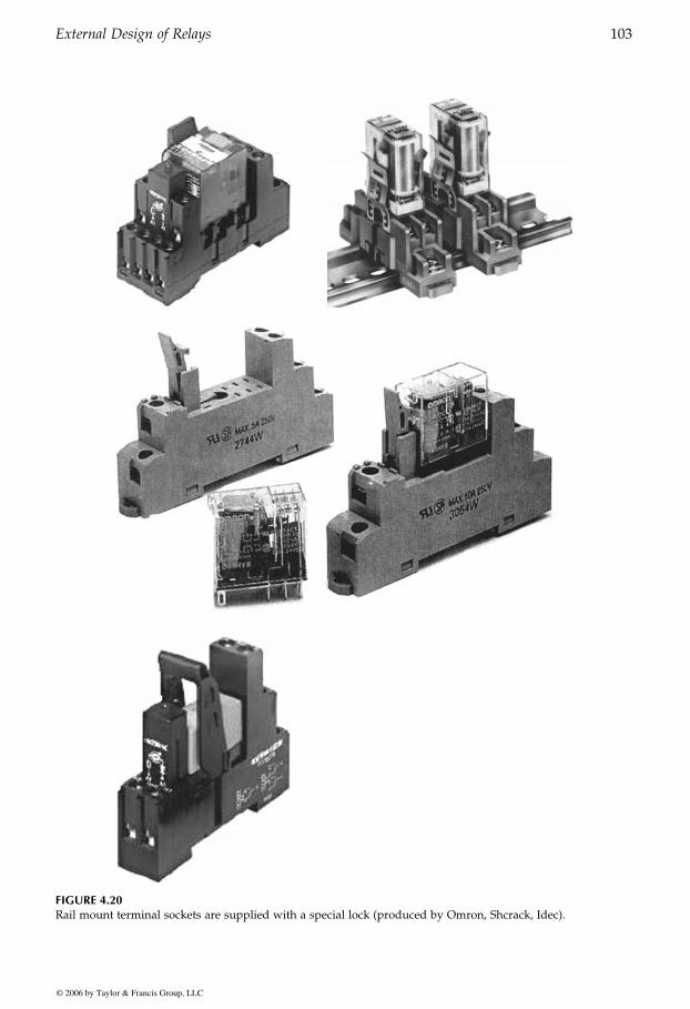
FIGURE 4.20Rail mount terminal sockets are supplied with a special lock (produced by Omron, Shcrack, Idec).
GUREVICH / Electric Relays: Principles and Practises DK884X_c004 Final Proof page 103 29.10.2005 11:15pm
External Design of Relays 103
© 2006 by Taylor & Francis Group, LLC
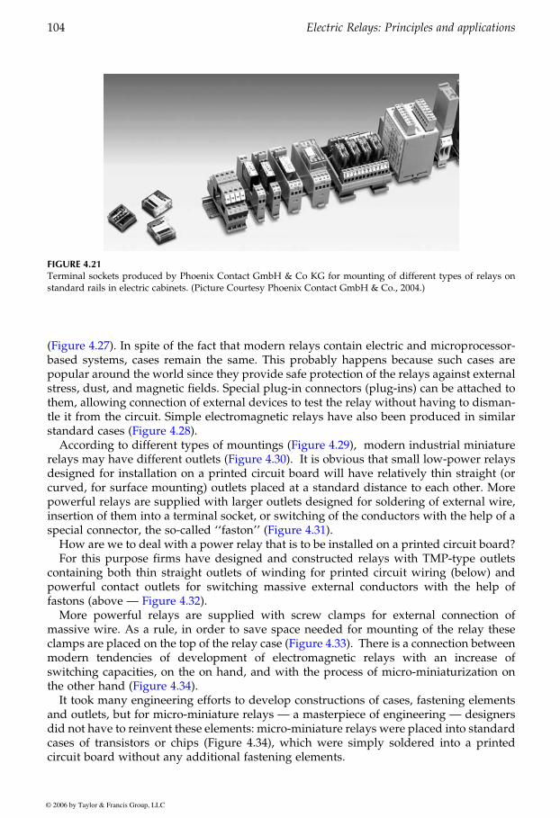
based systems, cases remain the same. This probably happens because such cases arepopular around the world since they provide safe protection of the relays against externalstress, dust, and magnetic fields. Special plug-in connectors (plug-ins) can be attached tothem, allowing connection of external devices to test the relay without having to disman-tle it from the circuit. Simple electromagnetic relays have also been produced in similar
modern industrial miniatureIt is obvious that small low-power relays
designed for installation on a printed circuit board will have relatively thin straight (orcurved, for surface mounting) outlets placed at a standard distance to each other. Morepowerful relays are supplied with larger outlets designed for soldering of external wire,
How are we to deal with a power relay that is to be installed on a printed circuit board?For this purpose firms have designed and constructed relays with TMP-type outlets
containing both thin straight outlets of winding for printed circuit wiring (below) andpowerful contact outlets for switching massive external conductors with the help of
More powerful relays are supplied with screw clamps for external connection ofmassive wire. As a rule, in order to save space needed for mounting of the relay these
modern tendencies of development of electromagnetic relays with an increase ofswitching capacities, on the on hand, and with the process of micro-miniaturization on
It took many engineering efforts to develop constructions of cases, fastening elementsand outlets, but for micro-miniature relays — a masterpiece of engineering — designersdid not have to reinvent these elements: micro-miniature relays were placed into standardcases of transistors or chips (Figure 4.34), which were simply soldered into a printedcircuit board without any additional fastening elements.
FIGURE 4.21Terminal sockets produced by Phoenix Contact GmbH & Co KG for mounting of different types of relays onstandard rails in electric cabinets. (Picture Courtesy Phoenix Contact GmbH & Co., 2004.)
GUREVICH / Electric Relays: Principles and Practises DK884X_c004 Final Proof page 104 29.10.2005 11:15pm
104 Electric Relays: Principles and applications
© 2006 by Taylor & Francis Group, LLC
(Figure 4.27). In spite of the fact that modern relays contain electric and microprocessor-
standard cases (Figure 4.28).According to different types of mountings (Figure 4.29),
insertion of them into a terminal socket, or switching of the conductors with the help of a
relays may have different outlets (Figure 4.30).
special connector, the so-called ‘‘faston’’ (Figure 4.31).
fastons (above — Figure 4.32).
clamps are placed on the top of the relay case (Figure 4.33). There is a connection between
the other hand (Figure 4.34).

(a)
(b)
(c)
FIGURE 4.22(a) Construction of a container with a relay installed inside. Produced by Phoenix Contact GmbH & Co KG.1 — ready-assembled electric relay; 2 — plastic case of the relay; 3 — container with pin-like outlets produced byPhoenix Contact; 4 — plastic case of the container. (b) Installation of containers with electromagnetic relays onmounting terminal sockets (Phoenix Contact). (c) Construction of a cell of a mounting terminal socket producedby Phoenix Contact. (Picture Courtesy Phoenix Contact GmbH & Co., 2005.)
GUREVICH / Electric Relays: Principles and Practises DK884X_c004 Final Proof page 105 29.10.2005 11:16pm
External Design of Relays 105
© 2006 by Taylor & Francis Group, LLC
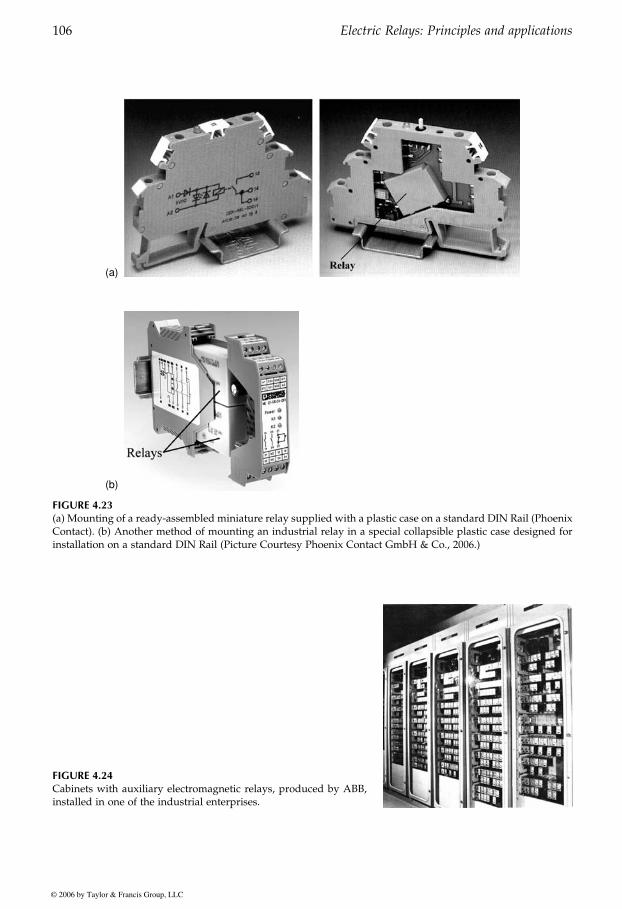
(a)
(b)
FIGURE 4.23(a) Mounting of a ready-assembled miniature relay supplied with a plastic case on a standard DIN Rail (PhoenixContact). (b) Another method of mounting an industrial relay in a special collapsible plastic case designed forinstallation on a standard DIN Rail (Picture Courtesy Phoenix Contact GmbH & Co., 2006.)
FIGURE 4.24Cabinets with auxiliary electromagnetic relays, produced by ABB,installed in one of the industrial enterprises.
GUREVICH / Electric Relays: Principles and Practises DK884X_c004 Final Proof page 106 29.10.2005 11:16pm
106 Electric Relays: Principles and applications
© 2006 by Taylor & Francis Group, LLC

(a) (b)
FIGURE 4.25(a) Modern electro-magnetic relay of RXMA-1 type used in cabinets of relay protection as an auxiliary relay(produced by ABB). (b) Terminal socket of RXMA-1 relay. (From ASEA Relays, Buyers Guide B03-00011E.)
FIGURE 4.26Peculiarities of mounting and elements of construction of a relay socket produced by ABB. (From ASEA Relays,Buyers Guide B03-00011E.)
FIGURE 4.27Relays of differential protection produced by General Electric
GUREVICH / Electric Relays: Principles and Practises DK884X_c004 Final Proof page 107 29.10.2005 11:16pm
External Design of Relays 107
© 2006 by Taylor & Francis Group, LLC
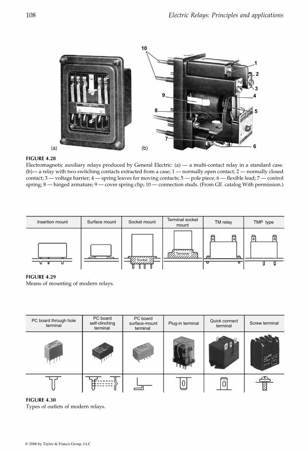
(a) (b)
FIGURE 4.28Electromagnetic auxiliary relays produced by General Electric: (a) — a multi-contact relay in a standard case.(b)— a relay with two switching contacts extracted from a case; 1 — normally open contact; 2 — normally closedcontact; 3 — voltage barrier; 4 — spring leaves for moving contacts; 5 — pole piece; 6 — flexible lead; 7 — controlspring; 8 — hinged armature; 9 — cover spring clip; 10 — connection studs. (From GE. catalog With permission.)
FIGURE 4.29Means of mounting of modern relays.
FIGURE 4.30Types of outlets of modern relays.
GUREVICH / Electric Relays: Principles and Practises DK884X_c004 Final Proof page 108 29.10.2005 11:16pm
108 Electric Relays: Principles and applications
© 2006 by Taylor & Francis Group, LLC

FIGURE 4.31Faston-type connectors and their use for relay connection
FIGURE 4.32Relays with hybrid outlets.
GUREVICH / Electric Relays: Principles and Practises DK884X_c004 Final Proof page 109 29.10.2005 11:16pm
External Design of Relays 109
© 2006 by Taylor & Francis Group, LLC
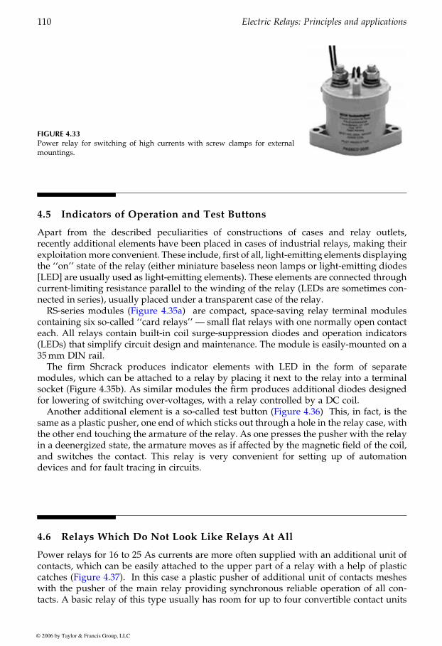
4.5 Indicators of Operation and Test Buttons
Apart from the described peculiarities of constructions of cases and relay outlets,recently additional elements have been placed in cases of industrial relays, making theirexploitationmore convenient. These include, first of all, light-emitting elements displayingthe ‘‘on’’ state of the relay (either miniature baseless neon lamps or light-emitting diodes[LED] are usually used as light-emitting elements). These elements are connected throughcurrent-limiting resistance parallel to the winding of the relay (LEDs are sometimes con-nected in series), usually placed under a transparent case of the relay.
are compact, space-saving relay terminal modulescontaining six so-called ‘‘card relays’’ — small flat relays with one normally open contacteach. All relays contain built-in coil surge-suppression diodes and operation indicators(LEDs) that simplify circuit design and maintenance. The module is easily-mounted on a35mm DIN rail.
The firm Shcrack produces indicator elements with LED in the form of separatemodules, which can be attached to a relay by placing it next to the relay into a terminalsocket (Figure 4.35b). As similar modules the firm produces additional diodes designedfor lowering of switching over-voltages, with a relay controlled by a DC coil.
This, in fact, is thesame as a plastic pusher, one end of which sticks out through a hole in the relay case, withthe other end touching the armature of the relay. As one presses the pusher with the relayin a deenergized state, the armature moves as if affected by the magnetic field of the coil,and switches the contact. This relay is very convenient for setting up of automationdevices and for fault tracing in circuits.
4.6 Relays Which Do Not Look Like Relays At All
Power relays for 16 to 25 As currents are more often supplied with an additional unit ofcontacts, which can be easily attached to the upper part of a relay with a help of plastic
In this case a plastic pusher of additional unit of contacts mesheswith the pusher of the main relay providing synchronous reliable operation of all con-tacts. A basic relay of this type usually has room for up to four convertible contact units
FIGURE 4.33Power relay for switching of high currents with screw clamps for externalmountings.
GUREVICH / Electric Relays: Principles and Practises DK884X_c004 Final Proof page 110 29.10.2005 11:16pm
110 Electric Relays: Principles and applications
© 2006 by Taylor & Francis Group, LLC
RS-series modules (Figure 4.35a)
Another additional element is a so-called test button (Figure 4.36)
catches (Figure 4.37).
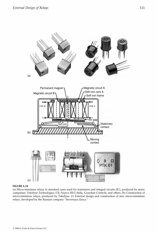
Permanent magnet
Magnetic circuit B
Soft ironarmature
Magnetic circuit A
Soft iron core ASoft iron frame
Air gap
Stationarycontact
Movingcontact
(a)
(b)
(c)
FIGURE 4.34(a) Micro-miniature relays in standard cases used for transistors and integral circuits (IC), produced by manycompanies: Teledyne Technologies, CII, Nuova HI-G Italia, Guardian Controls, and others. (b) Construction ofmicro-miniature relays, produced by Teledyne. (c) External design and construction of new micro-miniaturerelays, developed by the Russian company ‘‘Severnaya Zarya.’’
GUREVICH / Electric Relays: Principles and Practises DK884X_c004 Final Proof page 111 29.10.2005 11:16pm
External Design of Relays 111
© 2006 by Taylor & Francis Group, LLC
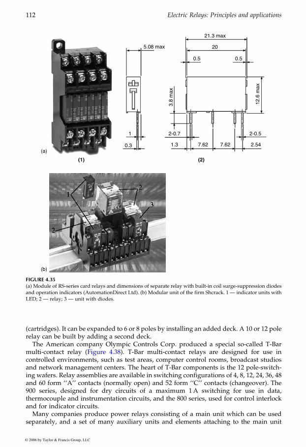
(cartridges). It can be expanded to 6 or 8 poles by installing an added deck. A 10 or 12 polerelay can be built by adding a second deck.
The American company Olympic Controls Corp. produced a special so-called T-Barmulti-contact relay T-Bar multi-contact relays are designed for use incontrolled environments, such as test areas, computer control rooms, broadcast studiosand network management centers. The heart of T-Bar components is the 12 pole-switch-ing wafers. Relay assemblies are available in switching configurations of 4, 8, 12, 24, 36, 48and 60 form ‘‘A’’ contacts (normally open) and 52 form ‘‘C’’ contacts (changeover). The900 series, designed for dry circuits of a maximum 1A switching for use in data,thermocouple and instrumentation circuits, and the 800 series, used for control interlockand for indicator circuits.
Many companies produce power relays consisting of a main unit which can be usedseparately, and a set of many auxiliary units and elements attaching to the main unit
(a)
(b)
FIGURE 4.35(a) Module of RS-series card relays and dimensions of separate relay with built-in coil surge-suppression diodesand operation indicators (AutomationDirect Ltd). (b) Modular unit of the firm Shcrack. 1 — indicator units withLED; 2 — relay; 3 — unit with diodes.
GUREVICH / Electric Relays: Principles and Practises DK884X_c004 Final Proof page 112 29.10.2005 11:16pm
112 Electric Relays: Principles and applications
© 2006 by Taylor & Francis Group, LLC
(Figure 4.38).

FIGURE 4.36Relays with test buttons.
(a)
(b)
FIGURE 4.37Power relays modular construction with attached units of additional contacts. (a — Telemechanique;b — Square-D).
GUREVICH / Electric Relays: Principles and Practises DK884X_c004 Final Proof page 113 29.10.2005 11:16pm
External Design of Relays 113
© 2006 by Taylor & Francis Group, LLC
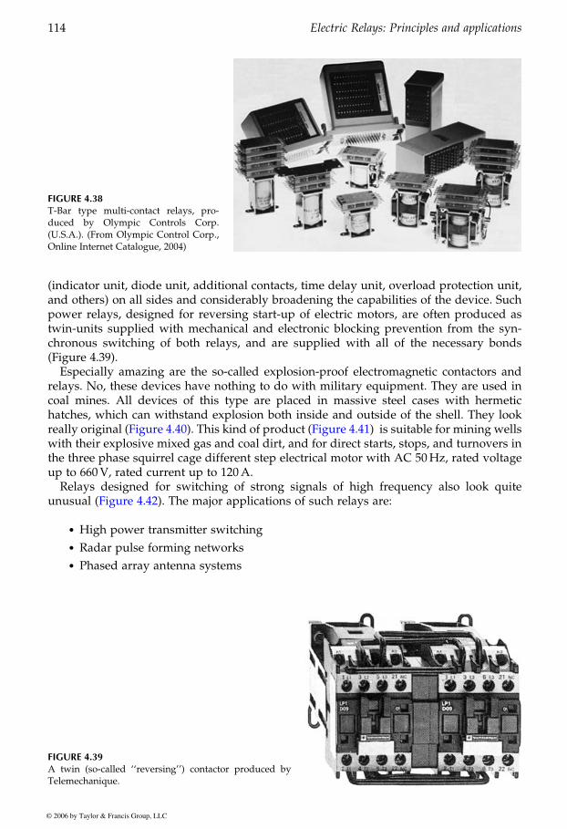
(indicator unit, diode unit, additional contacts, time delay unit, overload protection unit,and others) on all sides and considerably broadening the capabilities of the device. Suchpower relays, designed for reversing start-up of electric motors, are often produced astwin-units supplied with mechanical and electronic blocking prevention from the syn-chronous switching of both relays, and are supplied with all of the necessary bonds(Figure 4.39).
Especially amazing are the so-called explosion-proof electromagnetic contactors andrelays. No, these devices have nothing to do with military equipment. They are used incoal mines. All devices of this type are placed in massive steel cases with hermetichatches, which can withstand explosion both inside and outside of the shell. They look
with their explosive mixed gas and coal dirt, and for direct starts, stops, and turnovers inthe three phase squirrel cage different step electrical motor with AC 50Hz, rated voltageup to 660V, rated current up to 120A.
Relays designed for switching of strong signals of high frequency also look quite
. High power transmitter switching
. Radar pulse forming networks
. Phased array antenna systems
FIGURE 4.38T-Bar type multi-contact relays, pro-duced by Olympic Controls Corp.(U.S.A.). (From Olympic Control Corp.,Online Internet Catalogue, 2004)
FIGURE 4.39A twin (so-called ‘‘reversing’’) contactor produced byTelemechanique.
GUREVICH / Electric Relays: Principles and Practises DK884X_c004 Final Proof page 114 29.10.2005 11:16pm
114 Electric Relays: Principles and applications
© 2006 by Taylor & Francis Group, LLC
really original (Figure 4.40). This kind of product (Figure 4.41) is suitable for mining wells
unusual (Figure 4.42). The major applications of such relays are:
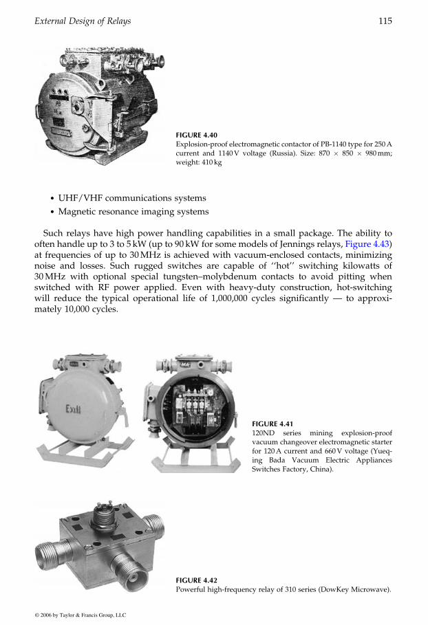
. UHF/VHF communications systems
. Magnetic resonance imaging systems
Such relays have high power handling capabilities in a small package. The ability to
at frequencies of up to 30MHz is achieved with vacuum-enclosed contacts, minimizingnoise and losses. Such rugged switches are capable of ‘‘hot’’ switching kilowatts of30MHz with optional special tungsten–molybdenum contacts to avoid pitting whenswitched with RF power applied. Even with heavy-duty construction, hot-switchingwill reduce the typical operational life of 1,000,000 cycles significantly — to approxi-mately 10,000 cycles.
FIGURE 4.40Explosion-proof electromagnetic contactor of PB-1140 type for 250Acurrent and 1140V voltage (Russia). Size: 870 � 850 � 980mm;weight: 410 kg
FIGURE 4.41120ND series mining explosion-proofvacuum changeover electromagnetic starterfor 120A current and 660V voltage (Yueq-ing Bada Vacuum Electric AppliancesSwitches Factory, China).
FIGURE 4.42Powerful high-frequency relay of 310 series (DowKey Microwave).
GUREVICH / Electric Relays: Principles and Practises DK884X_c004 Final Proof page 115 29.10.2005 11:16pm
External Design of Relays 115
© 2006 by Taylor & Francis Group, LLC
often handle up to 3 to 5 kW (up to 90 kW for some models of Jennings relays, Figure 4.43)
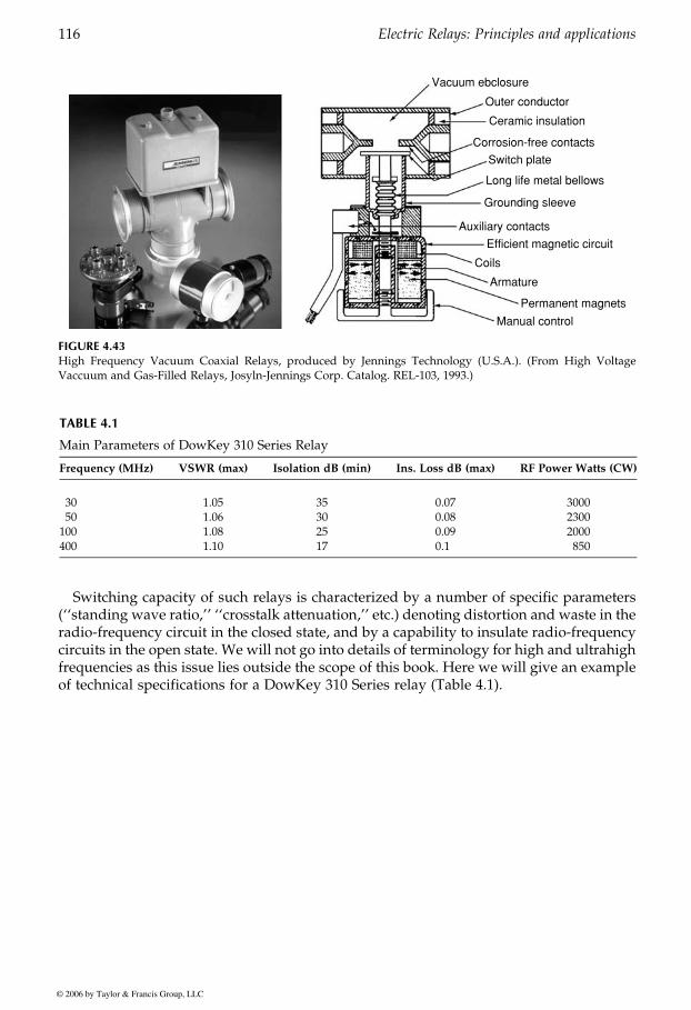
Switching capacity of such relays is characterized by a number of specific parameters(‘‘standing wave ratio,’’ ‘‘crosstalk attenuation,’’ etc.) denoting distortion and waste in theradio-frequency circuit in the closed state, and by a capability to insulate radio-frequencycircuits in the open state. We will not go into details of terminology for high and ultrahighfrequencies as this issue lies outside the scope of this book. Here we will give an exampleof technical specifications for a DowKey 310 Series relay (Table 4.1).
Vacuum ebclosure
Outer conductor
Ceramic insulation
Corrosion-free contacts
Switch plate
Long life metal bellows
Grounding sleeve
Auxiliary contacts
Efficient magnetic circuit
Coils
Armature
Permanent magnets
Manual control
FIGURE 4.43High Frequency Vacuum Coaxial Relays, produced by Jennings Technology (U.S.A.). (From High VoltageVaccuum and Gas-Filled Relays, Josyln-Jennings Corp. Catalog. REL-103, 1993.)
TABLE 4.1
Main Parameters of DowKey 310 Series Relay
Frequency (MHz) VSWR (max) Isolation dB (min) Ins. Loss dB (max) RF Power Watts (CW)
30 1.05 35 0.07 300050 1.06 30 0.08 2300100 1.08 25 0.09 2000400 1.10 17 0.1 850
GUREVICH / Electric Relays: Principles and Practises DK884X_c004 Final Proof page 116 29.10.2005 11:16pm
116 Electric Relays: Principles and applications
© 2006 by Taylor & Francis Group, LLC