electrical and ignition - Мotorka.org - моторные...
TRANSCRIPT

2B-–190-831996R1 JUNE 1996 ELECTRICAL AND IGNITION
ELECTRICAL ANDIGNITION
CDM IGNITION
2
B

2B-0 90-831996R1 JUNE 1996ELECTRICAL AND IGNITION
Table Of ContentsPage Page
Special Tools Required 2B-1. . . . . . . . . . . . . . . . . . . General 2B-1. . . . . . . . . . . . . . . . . . . . . . . . . . . . . . . . . Principles of Operation 2B-1. . . . . . . . . . . . . . . . . . . . Test Procedures 2B-1. . . . . . . . . . . . . . . . . . . . . . . . .
Testing For Spark 2B-2. . . . . . . . . . . . . . . . . . . . . Ignition Diagnostic Procedures 2B-3. . . . . . . . . . . . .
Testing Voltage Output to CDM 2B-3. . . . . . . . . Testing Stator Resistance - 95/120 HP 2B-5. . .
Trigger - 95/120 2B-5. . . . . . . . . . . . . . . . . . . Capacitor discharge Module 2B-6. . . . . . . .
Ignition Components Removaland Installation 2B-7. . . . . . . . . . . . . . . . . . . . . . .
Removing Flywheel 2B-8. . . . . . . . . . . . . . . . . . . . . . Installing Flywheel 2B-9. . . . . . . . . . . . . . . . . . . . . . . . Removing Stator 2B-9. . . . . . . . . . . . . . . . . . . . . . . . . Installing Stator 2B-9. . . . . . . . . . . . . . . . . . . . . . . . . . Removing Trigger 2B-9. . . . . . . . . . . . . . . . . . . . . . . . Installing Trigger 2B-10. . . . . . . . . . . . . . . . . . . . . . . . Removing CDM 2B-10. . . . . . . . . . . . . . . . . . . . . . . . . Installing CDM 2B-10. . . . . . . . . . . . . . . . . . . . . . . . . . Wiring Diagram 95 HP 2B-12. . . . . . . . . . . . . . . . . . . Wiring Diagram 120 HP 2B-13. . . . . . . . . . . . . . . . . .

2B-190-831996R1 JUNE 1996 ELECTRICAL AND IGNITION
Special Tools RequiredMultimeter/ DVA Tester 91-99750
Spark Tester 91-850439
55117
Ignition Test Harness 84-825207A2
GeneralThe ignition system is self-energizing (creates it’sown power for ignition) and has proven reliability.Should testing be required it is important to check allcomponents in the order outlined.
IMPORTANT: Read the entire procedure before at-tempting to test components.
The procedures in this section are designed to testthe complete ignition system. In an actual situation,test only the components that control the misfiring cyl-inder(s).
WARNINGWhen testing or servicing the ignition systemhigh voltage is present; be extremely cautious!DO NOT TOUCH OR DISCONNECT any ignitioncomponents while engine is cranking or running.
Principles of OperationCapacitor Discharge Module (CDM)Ignition SystemThe ignition system is alternator driven with distribu-torless capacitor discharge. Major components of theignition system are the flywheel, stator, trigger, capac-itor discharge module, and spark plugs.
The stator assembly is mounted stationary below theflywheel and has one capacitor charging coil.
The flywheel is fitted with permanent magnets insidethe outer rim. As the flywheel rotates the permanentmagnets pass the capacitor charging coil. Thiscauses the capacitor charging coils to produce ACvoltage. The AC voltage is conducted to the CDM(Capacitor Discharge Module) where it is rectified andstored in a capacitor.
The trigger assembly (also mounted under the fly-wheel) has one coil for each cylinder. The flywheelhas a second set of permanent magnets locatedaround the center hub. As the flywheel rotates thesecond set of magnets pass the trigger coils. Thiscauses the trigger coils, in turn, to produce an AC volt-age that is conducted to an electronic switch (SCR)in the CDM.
The SCR switch discharges the capacitor voltage intothe primary side of the ignition coil.
The ignition coil multiplies this voltage to a value highenough to jump the gap at the spark plug.
The preceding sequence occurs once per engine rev-olution for each cylinder.
Spark timing is changed (advanced/retarded) by ro-tating the trigger assembly which changes each trig-ger coil position in relation to the permanent magnetson the flywheel hub.
Test Procedures
Failure to comply with the following items mayresult in damage to the ignition system.
CAUTION
� DO NOT reverse battery cable connections. Thebattery negative cable is (–) ground. DO NOT“spark” battery terminals with battery cable con-nections to check polarity.
� DO NOT disconnect battery cables while engineis running.
Before troubleshooting the ignition system:

2B-2 90-831996R1 JUNE 1996ELECTRICAL AND IGNITION
� Check that plug-in connectors are fully engagedand free of corrosion (trigger connectors are lo-cated behind the ignition plate).
� Check that electrical components are groundedto the ignition plate and that ignition plate isgrounded to the engine block.
� Check for disconnected wires, short and opencircuits.
Testing For Spark1. Adjust spark tester to a 7/16” gap setting.
7/16 in.
2. Secure spark tester to a good engine ground.
3. Remove leads from spark plugs.
4. Connect spark plug leads to corresponding sparktester leads.
5. Remove spark plugs.
6. Turn the ignition key to the “on” position.
7. Crank motor.
NOTE: Battery voltage must be a minimum of 10 voltsat the starter solenoid to adequately crank the en-gine.
Results: Action Required:
Spark jumps 7/16” gap(all cylinders)
Ignition system opera-tional - If required,check timing & setup.
No spark Go to next step.
No spark on 1 or 2 cylin-ders
Go to Ignition Diagnos-tic Procedures.
8. Disconnect all CDM plugs and verify that eachground lead has continuity to engine ground.
a
a - Each CDM ground wire is labeled “A”.
9. Re-connect all CDMs.

2B-390-831996R1 JUNE 1996 ELECTRICAL AND IGNITION
10. Check that safety stop switch lanyard is in place.If safety lanyard is NOT in place, spark plugs willnot fire.
11. Sport Jet Models Only: Isolate the rev limiter bydisconnecting the black/yellow lead to the rev lim-iter. Tape back the black/yellow lead. Re-test forspark. If all cylinders spark, replace rev limiter. Nospark: continue with next step.
12. Isolate the stop circuit by disconnecting black/yellow bullet connector located on the ignitionplate wire bundle.
IMPORTANT: Be sure this lead is not grounded.
13. Crank motor.
Results: Action Required:
All cylinders spark nor-mally
Repair stop circuit: igni-tion key switch and/orboat wiring.
No spark (all cylinders) Go to Ignition Diagnos-tic Procedures.
14. Re-connect rev limiter and/or stop circuit.
95 HP
IMPORTANT: The voltage return path for #1 CDM isthrough either #2 or #3 CDM. The return path for #2and #3 is through #1 CDM. If the #1 CDM is discon-nected the engine will loose fire on all cylinders asthe capacitors cannot be charged.
#1
#2#3
NOTE: Each CDM is grounded through the engine wir-ing harness via the connector plug. It is not necessaryto have the CDM mounted on the ignition plate for test-ing.
120 HP
IMPORTANT: The voltage return path for #1 and #2CDM is through either #3 or #4 CDM. The returnpath for #3 and #4 is through either #1 or #2 CDM.
#1
#3#4
#2
Ignition DiagnosticProcedures
PROBLEM CORRECTION
1. No spark on one cylin-der
1. Plug in a CDM that isknown to be good. Ifspark returns, replacebad CDM.
2. No change: go to Test-ing Voltage Output toCDM.
3. No spark on all cylin-ders
Go to Testing VoltageOutput - Test all CDMs.
Testing Voltage Output to CDM
CAUTIONTo protect against meter and/or component dam-age, observe the following precautions:
� INSURE that the Positive (+) meter lead is con-nected to the DVA receptacle on the meter.
� DO NOT CHANGE meter selector switch positionwhile engine is running and/or being “cranked”.
NOTE: Each CDM is grounded through the engine wir-ing harness via the connector plug. It is not necessaryto have the CDM mounted on the ignition plate for test-ing.

2B-4 90-831996R1 JUNE 1996ELECTRICAL AND IGNITION
1. Make sure all CDMs are plugged in.
2. Test Stator and Trigger voltage to CDM:
a. Install test harness between Ignition Harnessand CDM.
bac
a - Stator/Trigger Harnessb - Test Harnessc - Capacitor Discharge Module
b. Perform the following tests:
CRANKING ENGINE:
Test each CDM.
Stator Output Test 400 DVA Scale
Positive MeterLead (+)
NegativeMeter Lead (–)
DVAReading
Connect toGreen TestHarness Lead
Connect toBlack Test Har-ness Lead
100 - 350
If only one CDM stator reading is below specifications,replace that CDM. If all CDM stator voltage readingsare low, go to Testing Stator Resistance.
GR
N BLK
Test each CDM.
Trigger Output Test 2 DVA Scale
Positive MeterLead (+)
NegativeMeter Lead (–)
DVAReading
White Test Har-ness Lead
Black Test Har-ness Lead 0.2 - 2.0
If reading is below specifications replace trigger. If read-ing is above specifications check CDM.
NOTE: If voltage remains low after installing a new trig-ger, replaced CDM.
WHT
BLK
ENGINE RUNNING AT IDLE:
It is not necessary to perform this test if the voltage out-put was tested in the previous step CRANKING EN-GINE.
Stator Output Test 400 DVA Scale
Positive MeterLead (+)
NegativeMeter Lead (–)
DVAReading
Connect toGreen TestHarness Lead
Connect toBlack Test Har-ness Lead
200 - 350
If stator output is low, go to Testing Stator Resistance.
Trigger Output Test 20 DVA Scale
Positive MeterLead (+)
NegativeMeter Lead (–)
DVAReading
White Test Har-ness Lead
Black Test Har-ness Lead 2 - 8 Volts
If reading is below specifications replace trigger. If read-ing is above specifications check CDM.
NOTE: If voltage remains low after installing a new trig-ger, replaced CDM.
http://motorka.org

2B-590-831996R1 JUNE 1996 ELECTRICAL AND IGNITION
Testing Stator Resistance - 95/120 HPDisconnect stator leads.
Stator Resistance TestR x 10 Ohms
Positive MeterLead (+)
NegativeMeter Lead (–)
R x 10 OhmsScale
Connect toWhite/Greenstator lead
Connect toGreen/Whitestator lead
500 - 600± 10%
Connect toWhite/Greenstator lead
Connect to en-gine ground No continuity
Connect toGreen/Whitestator lead
Connect to en-gine ground No continuity
IMPORTANT: If all CDM stator output voltage is lowand stator resistance tests are within specifica-tions, then each CDM (one at a time) must be re-placed with a CDM known to be good until statoroutput voltage returns to proper levels. This pro-cess of elimination will reveal a defective CDM.
RX10
TRIGGER - 95/120A resistance test is not used on the trigger. Test triggeras outlined under “Testing Voltage Output to CDM”.

2B-6 90-831996R1 JUNE 1996ELECTRICAL AND IGNITION
CAPACITOR DISCHARGE MODULE
A B C D
A - GroundB - Black/YellowC - Trigger ConnectionD - Stator Connection
IMPORTANT: Spark plug wires arescrewed into CDM.
A resistance check, although not necessary for any troubleshooting procedure, can be made of the CDM as fol-lows:
NOTE: This test can be performed using the test harness (p/n 84-825207A2). Do Not connect the test harnessplug to the stator/trigger engine wire harness.
CAPACITOR DISCHARGE MODULE
Connect Positive (+)Meter Lead To:
Connect Negative (–)Meter Lead To:
OhmsScale
Results:
Ground Pin (A)/ or Blacktest harness lead
White (C)/ or White testharness lead
R x 100 1250 � 100 Ohms
Green (D)/ or Green testharness lead
Ground Pin (A)/ or Blacktest harness lead
R x 1Diode Reading*
Continuity
Ground Pin (A) or Blacktest harness lead
Green (D)/ or Green testharness lead
R x 1Diode Reading*
No Continuity
Green (D)/ or Green testharness lead
Black/Yellow (B)/ or Black/Yellow test harness lead
R x 1Diode Reading*
No Continuity
Black/Yellow (B)/ or Black/Yellow test harness lead
Green (D)/ or Green testharness lead
R x 1Diode Reading*
Continuity
Spark Plug Terminal(At Spark Plug Boot)
Ground Pin (A) or Blacktest harness lead
R x 10 1050 � 150 Ohms
*Diode Readings: Due to the differences in test meters, results other than specified may be obtained. In such acase, reverse meter leads and re-test. If test results then read as specified CDM is O.K.. The diode measurementsabove will be opposite if using a Fluke equivalent multimeter.
b
a
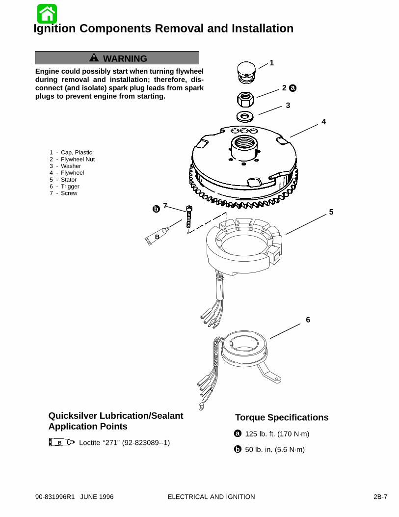
50 lb. in. (5.6 N·m)
Torque SpecificationsQuicksilver Lubrication/SealantApplication Points
a
b
B
B Loctite “271” (92-823089--1)
1
2
3
4
5
6
1 - Cap, Plastic2 - Flywheel Nut3 - Washer4 - Flywheel5 - Stator6 - Trigger7 - Screw
125 lb. ft. (170 N·m)
7
2B-790-831996R1 JUNE 1996 ELECTRICAL AND IGNITION
Ignition Components Removal and Installation
WARNINGEngine could possibly start when turning flywheelduring removal and installation; therefore, dis-connect (and isolate) spark plug leads from sparkplugs to prevent engine from starting.

1
3
1 - CDM (Capacitor Discharge Module)2 - Voltage Regulator3 - 20 Ampere Fuse4 - CDM Wire Harness5 - Engine Wire Harness6 - Ignition Plate7 - Rev Limiter
6
2
4
5
7
2B-8 90-831996R1 JUNE 1996ELECTRICAL AND IGNITION
Ignition Components Removal and Installation(4 - Cylinder Shown)
2B-990-831996R1 JUNE 1996 ELECTRICAL AND IGNITION
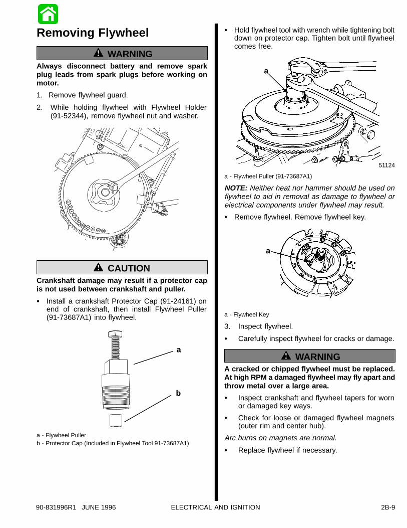
Removing Flywheel
WARNINGAlways disconnect battery and remove spar kplug leads from spark plugs before working onmotor.
1. Remove flywheel guard.
2. While holding flywheel with Flywheel Holder(91-52344), remove flywheel nut and washer.
Crankshaft damage may result if a protector capis not used between crankshaft and puller.
CAUTION
� Install a crankshaft Protector Cap (91-24161) onend of crankshaft, then install Flywheel Puller(91-73687A1) into flywheel.
a
b
a - Flywheel Pullerb - Protector Cap (Included in Flywheel Tool 91-73687A1)
� Hold flywheel tool with wrench while tightening boltdown on protector cap. Tighten bolt until flywheelcomes free.
51124
a
a - Flywheel Puller (91-73687A1)
NOTE: Neither heat nor hammer should be used onflywheel to aid in removal as damage to flywheel orelectrical components under flywheel may result.
� Remove flywheel. Remove flywheel key.
a
a - Flywheel Key
3. Inspect flywheel.
� Carefully inspect flywheel for cracks or damage.
WARNINGA cracked or chipped flywheel must be replaced.At high RPM a damaged flywheel may fly apart andthrow metal over a large area.
� Inspect crankshaft and flywheel tapers for wornor damaged key ways.
� Check for loose or damaged flywheel magnets(outer rim and center hub).
Arc burns on magnets are normal.
� Replace flywheel if necessary.

2B-10 90-831996R1 JUNE 1996ELECTRICAL AND IGNITION
Installing Flywheel1. Clean tapered surfaces of flywheel and crank-
shaft with solvent.
� Blow dry tapered surfaces with compressed air.
If the flywheel key appears damaged in any way re-place it.
2. Install flywheel key in crankshaft slot with outeredge of key parallel to center line of crankshaft.
a
a - Flywheel Key
3. Install flywheel.
� Place flywheel down over crankshaft.
� Install flywheel nut.
� Torque flywheel nut to 125 lb. ft. (169.5 N·m).
Removing Stator1. Remove flywheel.
SEE “REMOVING FLYWHEEL” IN THIS SECTION.
2. Remove yellow stator leads from rectifier/regula-tor leads.
3. Disconnect all stator leads from CDM wire har-ness.
Removal of ignition plate may be necessary to gainaccess to stator leads.
4. Remove screws and lift stator off bearing cage.
a
a
a - Stator Screws
Installing Stator1. Set stator on bearing cage. Secure with screws.
IMPORTANT: Be sure the stator is positioned sothe wire harness is on the port side of the motor.
2. Connect yellow stator leads to yellow voltageregulator leads.
3. Connect all stator leads to corresponding CDMwire harness.
4. Install flywheel.
Removing Trigger1. Remove flywheel.
SEE “REMOVING FLYWHEEL” IN THIS SECTION.
2. Remove stator.
SEE “REMOVING STATOR” IN THIS SECTION.
3. Disconnect trigger leads from CDM wire harness.
4. Disconnect spark control link from tower shaft.
2B-1190-831996R1 JUNE 1996 ELECTRICAL AND IGNITION
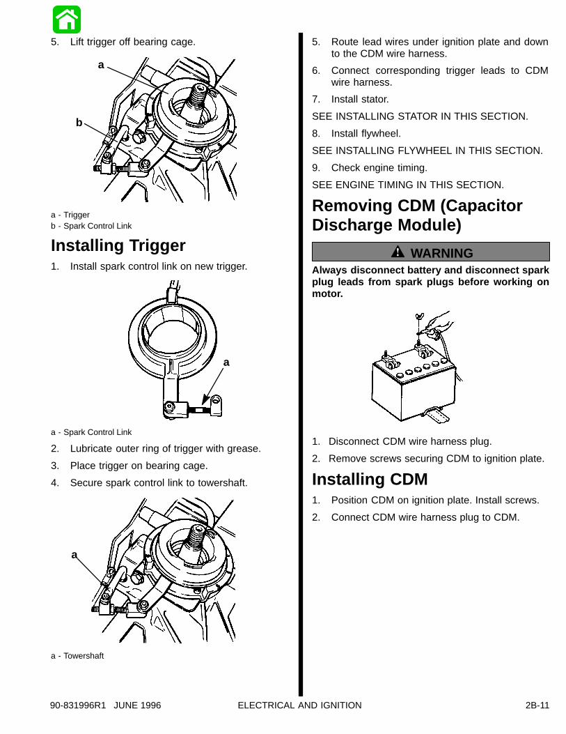
5. Lift trigger off bearing cage.
a
b
a - Triggerb - Spark Control Link
Installing Trigger1. Install spark control link on new trigger.
a
a - Spark Control Link
2. Lubricate outer ring of trigger with grease.
3. Place trigger on bearing cage.
4. Secure spark control link to towershaft.
a
a - Towershaft
5. Route lead wires under ignition plate and downto the CDM wire harness.
6. Connect corresponding trigger leads to CDMwire harness.
7. Install stator.
SEE INSTALLING STATOR IN THIS SECTION.
8. Install flywheel.
SEE INSTALLING FLYWHEEL IN THIS SECTION.
9. Check engine timing.
SEE ENGINE TIMING IN THIS SECTION.
Removing CDM (CapacitorDischarge Module)
WARNINGAlways disconnect battery and disconnect spar kplug leads from spark plugs before working onmotor.
1. Disconnect CDM wire harness plug.
2. Remove screws securing CDM to ignition plate.
Installing CDM1. Position CDM on ignition plate. Install screws.
2. Connect CDM wire harness plug to CDM.
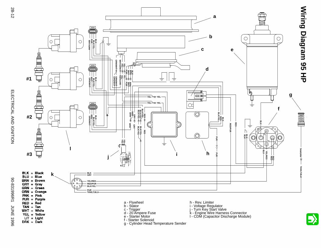
a - Flywheelb - Statorc - Triggerd - 20 Ampere Fusee - Starter Motorf - Starter Solenoidg - Cylinder Head Temperature Sender
h - Rev. Limiteri - Voltage Regulatorj - Turn Key Start Valvek - Engine Wire Harness Connectorl - CDM (Capacitor Discharge Module)
12345 6 7
8
BLKGRY
YEL/REDRED/PURBLK/YEL
PURTAN/LT.BLU
GR
N/W
HT
WH
T/G
RN
YE
L
BR
N
BLK
/YE
L
YEL
YEL
GR
Y
BLK
/YE
L
YEL
YEL
GR
Y
GR
N/W
HT W
HT
/GR
N
BR
N
RE
D/P
UR
RE
D
BLK
B
LKY
EL/R
ED
RE
DR
ED
BLK
WH
TW
HT
GR
N/W
HT
PU
R
RE
DR
ED
BLK
BLK
WH
T/G
RN
PU
R
BLKB
LK/Y
EL
PU
RP
UR
BLK
/YE
L
GR
N/W
HT
WH
TB
LK/Y
EL
BLK
GR
N/W
HT
BR
N BLK
/YE
LB
LK
TAN
/LT.BLU
TAN
/GR
N
BLK
BLK
/YE
LB
RN
PU
R
BR
NB
RN B
RN
BLK
/YE
LB
LK/Y
EL
a
b
c
d
e
f
g
hij
l
k
#3
#2
#1
YE
LY
EL
YE
LY
EL
YE
L
2B-12
90-831996R1 JU
NE
1996E
LEC
TR
ICA
L AN
D IG
NIT
ION
Wiring D
iagram 95 H
P

#4
#3
#2
#1
a
b
c
12345 6 7
8
BLKGRY
YEL/REDRED/PURBLK/YEL
PURTAN/LT.BLU
GR
N/W
HT
WH
T/G
RN
YE
LY
EL
BR
N
BLK
/YE
L
YEL
YEL
BLK
/YE
L
YEL
YEL
GR
N/W
HT
WH
T/G
RN
BR
N
RE
D/P
UR
RE
D
BLK
B
LKY
EL/R
ED
RE
DR
ED
BLK
WH
TW
HT
GR
N/W
HT
PU
R
RE
DR
ED B
LKB
LK
WH
T/G
RN
PU
R
BLK
BLK
/YE
L
PU
RP
UR
BLK
/YE
L
WH
T/G
RN
WH
TB
LK/Y
EL
BLK
GR
N/W
HT
BR
NB
LK/Y
EL
BLK
TAN
/LT.BLU
TAN
/GR
N
BLK
BLK
/YE
LB
RN
PU
R
BR
NB
RN
BR
N
YE
LY
EL
BLK
/YE
LB
LK/Y
EL
YE
LY
EL
GR
N/W
HT
DR
K.B
LUB
LK/Y
EL
BLK
WH
T/G
RN
GR
YG
RY
BLU
DR
K.B
LU
d
f
g
hi
j
k
l
e
a - Flywheelb - Statorc - Triggerd - 20 Ampere Fusee - Starter Motorf - Starter Solenoidg - Cylinder Head Temperature Sender
h - Rev. Limiteri - Voltage Regulatorj - Turn Key Start Valvek - Engine Wire Harness Connectorl - CDM (Capacitor Discharge Module)
2B-13
90-831996R1 JU
NE
1996E
LEC
TR
ICA
L AN
D IG
NIT
ION
Wiring D
iagram 120 H
P