electrical building services - cad-detaildrafting...
TRANSCRIPT

C-DD012 Edition 3
CAD & Detail Drafting Granville TAFE
Electrical Building Services
7771AG
7771AG Electrical Building Services Student Workbook
31/01/08 Page 2 Engineering Drafting – Granville TAFE
First Published February 2002 by Engineering Drafting Granville TAFE William Street Granville NSW 2164 This work is copyright. Any inquiries about the use of this material Should be directed to the publisher. TAFE New South Wales Technical and Further Education Commission 2002 1st Edition January 2002 2nd Edition July 2007 3rd Edition January 2008 National Library of Australia Publication Number:

7771AG Electrical Building Services Student Workbook
31/01/08 Page 3 Engineering Drafting – Granville TAFE
Conditions of Use: Module Resource Manuals National Metals and Engineering Courses This Student’s Manual has been developed by the Teaching Staff of the CAD & Detail Drafting Staff at Granville College of TAFE for use in the National Metals and Engineering Courses. It is supplied to you with the following conditions:
it may not be re-sold.
it may be freely used and reproduced by TAFE authorities for their internal use.
The NSW TAFE Commission holds copyright on behalf of the Crown.
The course of study outlined in this manual may not be delivered on a fee-for-service or income-generation basis without first contacting the Senior Head Teacher of CAD & Detail Drafting at Granville College of TAFE.
If you do not agree to these conditions of ownership and use, then please return this copy of the manual immediately. For any queries about these conditions or if you wish to discuss and aspect further, please contact the Senior Head Teacher of CAD & Detail Drafting at Granville College of TAFE.
Phone: 02-9682-0304 Fax: 02-9682-0229
Any breach of these conditions will be acted upon to prevent loss of rights to NSW TAFE and CAD & Detail Drafting at Granville TAFE.
7771AG Electrical Building Services Student Workbook
31/01/08 Page 4 Engineering Drafting – Granville TAFE
CONTENTS Conditions of Use:............................................................................................................................................ 3
CONTENTS ..................................................................................................................................................... 4
FEEDBACK:.................................................................................................................................................... 6
ACKNOWLEDGEMENTS ............................................................................................................................ 6
SUGGESTED LESSON PROGRAM ............................................................................................................ 7
O.H.& S. ISSUES: ........................................................................................................................................... 8 Step 1 - The Chair For Computer Operation............................................................................................. 8 Step 2 - Adjusting The Chair: .................................................................................................................... 8 Step 3 - Sitting At the Desk: ....................................................................................................................... 9 Step 4 - Positioning The Monitor: ............................................................................................................. 9 Step 5 - Organising Your Work-Space:...................................................................................................... 9 Step 6 - Keyboard Basics:.......................................................................................................................... 9 Step 7 - Mouse Basics:............................................................................................................................. 10 Step 8 - Eye Basics: ................................................................................................................................. 11 Step 9 – Exercises:................................................................................................................................... 12 Step 10 – Micro-Breaks: .......................................................................................................................... 13
TERMINOLOGY.......................................................................................................................................... 14
LESSON 1 - Lighting Diagrams & Symbols ............................................................................................... 15 Learning Outcomes:..................................................................................................................................... 15 General Information:.................................................................................................................................... 15 Australian Standards:................................................................................................................................... 15 Symbols: ...................................................................................................................................................... 15 Symbol Sizes: .............................................................................................................................................. 16 Line Construction & Pen Thicknesses:........................................................................................................ 17 Lighting Diagrams: ...................................................................................................................................... 17 Minimum Lighting Requirements: .............................................................................................................. 18 Types of Controls: ....................................................................................................................................... 19 Examples of Lights & Switches:.................................................................................................................. 19 Skill Practice Exercise: 7771AG-SP-01................................................................................................... 20
LESSON 2 - Power Diagrams & Symbols ................................................................................................... 21 Learning Outcomes:..................................................................................................................................... 21 Symbols: ...................................................................................................................................................... 21 Symbol Sizes: .............................................................................................................................................. 22 Power Outlets in Domestic Installations:..................................................................................................... 23 Types of Controls: ....................................................................................................................................... 24 Examples of Fittings: ................................................................................................................................... 24 Skill Practice Exercise: 7771AG-SP-01 (extension)................................................................................ 25
Lesson 3 - Telecommunication Symbols ...................................................................................................... 26 Learning Outcomes:..................................................................................................................................... 26 Outline: ........................................................................................................................................................ 26 Symbols: ...................................................................................................................................................... 26 Symbol Sizes: .............................................................................................................................................. 27 Examples of Telecommunication Fittings: .................................................................................................. 27 Skill Practice Exercise: 7771AG-SP-01 (extension)................................................................................ 29
LESSON 4 – Electrical Schedules ................................................................................................................ 30 Learning Outcomes:..................................................................................................................................... 30

7771AG Electrical Building Services Student Workbook
31/01/08 Page 5 Engineering Drafting – Granville TAFE
Electrical Schedules:.................................................................................................................................... 30 Properties of Electrical Schedules: .............................................................................................................. 30 Skill Practice Exercise: 7771AG-SP-02................................................................................................... 31 Skill Practice Exercise: 7771AG-SP-03................................................................................................... 32 Skill Practice Exercise: 7771AG-SP-04................................................................................................... 33
LESSON 5 ...................................................................................................................................................... 35 Assessment Test 1: ...................................................................................................................................... 35 Exercise ....................................................................................................................................................... 35
LESSON 6 - Riser Diagrams......................................................................................................................... 36 Learning Outcomes:..................................................................................................................................... 36 Riser Diagrams: ........................................................................................................................................... 36
Incoming Mains: ...................................................................................................................................... 36 Sub-mains System: ................................................................................................................................... 36 Electrical Installation:............................................................................................................................. 36
Pen Thicknesses & Line Construction:........................................................................................................ 37 Typical Abbreviations: ................................................................................................................................ 37 Skill Practice Exercise: 7771AG-SP-05................................................................................................... 38 Skill Practice Exercise 7771AG-SP-06................................................................................................... 38
LESSON 7 - Switchboard Layouts............................................................................................................... 40 Learning Outcomes:..................................................................................................................................... 40 Meter Boxes & Distribution Boards: ........................................................................................................... 40 Types of Switchboards: ............................................................................................................................... 40
Domestic Types:....................................................................................................................................... 40 Typical Dimensions of Switchboard Equipment: ........................................................................................ 43
Commercial and Industrial Types: .......................................................................................................... 44 Skill Practice Exercise 7771AG-SP-07................................................................................................... 46 Skill Practice Exercise 7771AG-SP-08................................................................................................... 46
LESSON 8 - Busway Systems ....................................................................................................................... 47 Learning Outcomes:..................................................................................................................................... 47 Overview: .................................................................................................................................................... 47 Pen Thicknesses & Line Construction:........................................................................................................ 48 Skill Practice Exercise 7771AG-SP-09:.................................................................................................. 49 Skill Practice Exercise 7771AG-SP-10:.................................................................................................. 49
LESSON 9 ...................................................................................................................................................... 50 Assessment Test 2: ...................................................................................................................................... 50 Exercise ....................................................................................................................................................... 50

7771AG Electrical Building Services Student Workbook
31/01/08 Page 6 Engineering Drafting – Granville TAFE
FEEDBACK: Your feedback is essential for improving the quality of these manuals. Please advise the appropriate industry specialist of any changes, additions, deletions or anything else you believe would improve the quality of this Student Workbook. Don’t assume that someone else will do it. Your comments can be made by photocopying the relevant pages and including your comments or suggestions. Forward your comments to:
CAD & Detail Drafting Granville TAFE William Street Granville NSW 2142
ACKNOWLEDGEMENTS This Student Workbook was produced by Warren Blackadder, CAD & Detail Drafting Granville TAFE, with the assistance from Mr. Brian Quinn of K.R. Sheather Northern Electrical Engineers and Contractors and Derek Page of Granville TAFE.
7771AG Electrical Building Services Student Workbook
31/01/08 Page 7 Engineering Drafting – Granville TAFE
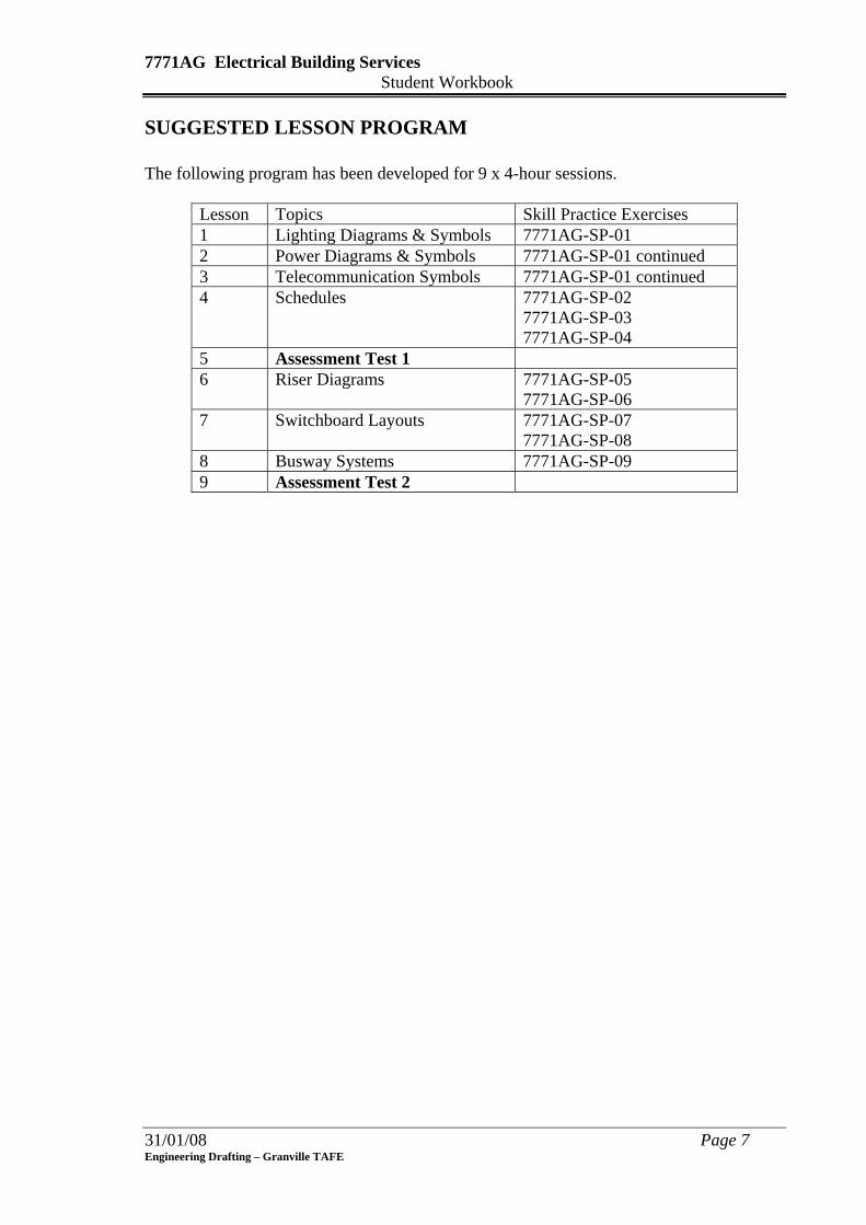
SUGGESTED LESSON PROGRAM The following program has been developed for 9 x 4-hour sessions.
Lesson Topics Skill Practice Exercises 1 Lighting Diagrams & Symbols 7771AG-SP-01 2 Power Diagrams & Symbols 7771AG-SP-01 continued 3 Telecommunication Symbols 7771AG-SP-01 continued 4 Schedules 7771AG-SP-02
7771AG-SP-03 7771AG-SP-04
5 Assessment Test 1 6 Riser Diagrams 7771AG-SP-05
7771AG-SP-06 7 Switchboard Layouts 7771AG-SP-07
7771AG-SP-08 8 Busway Systems 7771AG-SP-09 9 Assessment Test 2
7771AG Electrical Building Services Student Workbook
O.H.& S. ISSUES: Occupational Health and Safety is an important workplace issue; each year thousands of
workers suffer injuries that can be eliminated by adhering to basic good working practices
and postures. The main injuries that can occur while working at a computer are repetitive
strain injuries sustained maintaining the same position for hours on end without taking
breaks or stretching. Other injuries occur through not sitting correctly on chairs and
eyestrain.
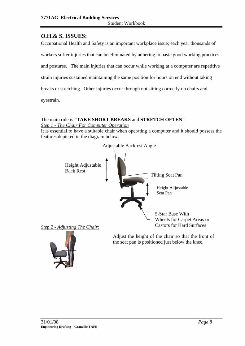
The main rule is “TAKE SHORT BREAKS and STRETCH OFTEN”. Step 1 - The Chair For Computer Operation It is essential to have a suitable chair when operating a computer and it should possess the features depicted in the diagram below.
31/01/08 Page 8 Engineering Drafting – Granville TAFE
Tilting Seat Pan
Height Adjustable
Adjustable Backrest Angle
Back Rest
Height Adjustable Seat Pan
Step 2 - Adjusting The Chair:
Adjust the height of the chair so that the front of the seat pan is positioned just below the knee.
5-Star Base With Wheels for Carpet Areas or Castors for Hard Surfaces
7771AG Electrical Building Services Student Workbook
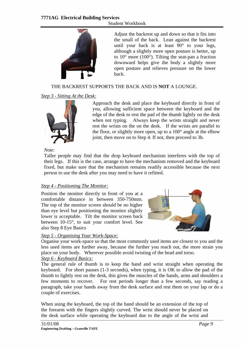
Adjust the backrest up and down so that it fits into the small of the back. Lean against the backrest until your back is at least 90° to your legs, although a slightly more open posture is better, up to 10° more (100°). Tilting the seat-pan a fraction downward helps give the body a slightly more open posture and relieves pressure on the lower back.
THE BACKREST SUPPORTS THE BACK AND IS NOT A LOUNGE.
Step 3 - Sitting At the Desk:
Approach the desk and place the keyboard directly in front of you, allowing sufficient space between the keyboard and the edge of the desk to rest the pad of the thumb lightly on the desk when not typing. Always keep the wrists straight and never rest the wrists on the on the desk. If the wrists are parallel to the floor, or slightly more open, up to a 100° angle at the elbow joint, then move on to Step 4. If not, then proceed to 3b.
Note: Taller people may find that the drop keyboard mechanism interferes with the top of their legs. If this is the case, arrange to have the mechanism removed and the keyboard fixed, but make sure that the mechanism remains readily accessible because the next person to use the desk after you may need to have it refitted.
Step 4 - Positioning The Monitor: Position the monitor directly in front of you at a comfortable distance in between 350-750mm. The top of the monitor screen should be no higher than eye level but positioning the monitor slightly lower is acceptable. Tilt the monitor screen back between 10-15°, to suit your comfort level. See also Step 8 Eye Basics Step 5 - Organising Your Work-Space: Organise your work-space so that the most commonly used items are closest to you and the less used items are further away, because the further you reach out, the more strain you place on your body. Wherever possible avoid twisting of the head and torso. Step 6 - Keyboard Basics: The general rule of thumb is to keep the hand and wrist straight when operating the keyboard. For short pauses (1-3 seconds), when typing, it is OK to allow the pad of the thumb to lightly rest on the desk, this gives the muscles of the hands, arms and shoulders a few moments to recover. For rest periods longer than a few seconds, say reading a paragraph, take your hands away from the desk surface and rest them on your lap or do a couple of exercises. When using the keyboard, the top of the hand should be an extension of the top of the forearm with the fingers slightly curved. The wrist should never be placed on the desk surface while operating the keyboard due to the angle of the wrist and
31/01/08 Page 9 Engineering Drafting – Granville TAFE
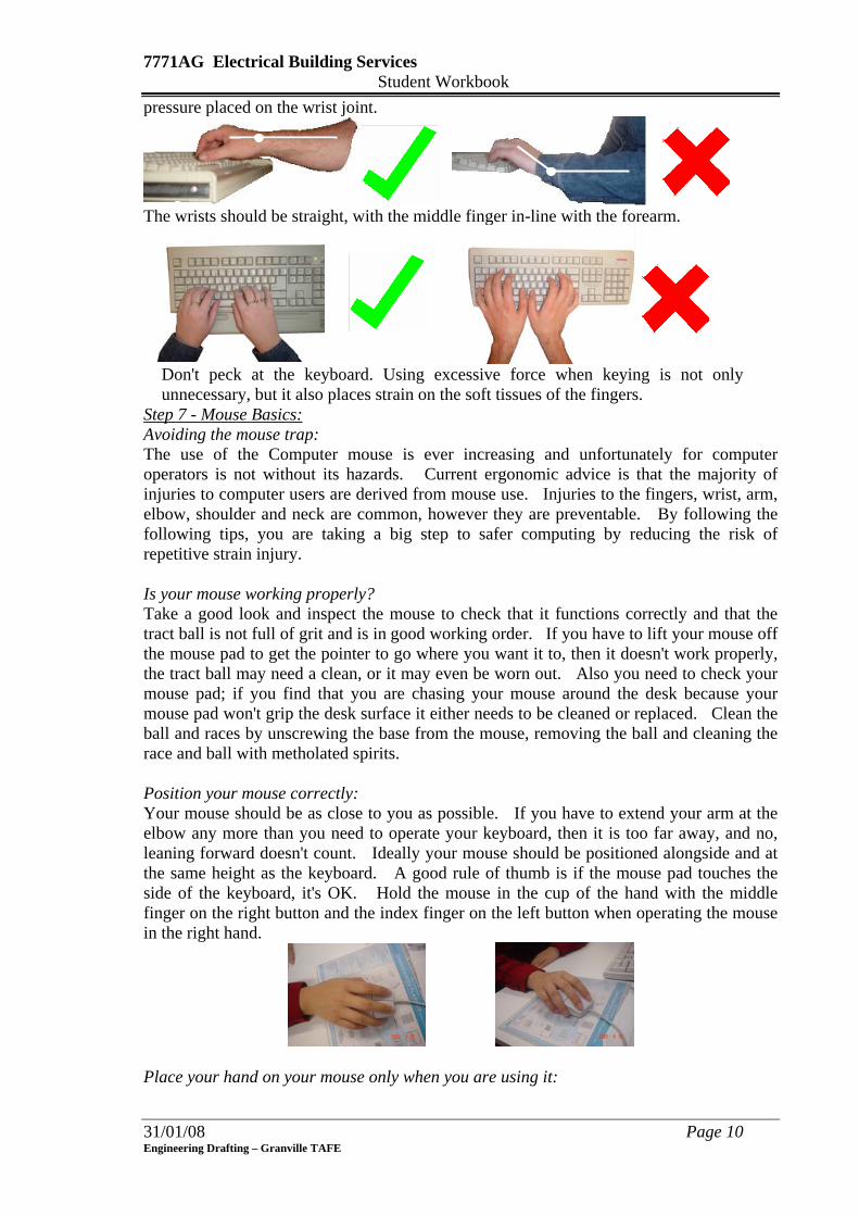
7771AG Electrical Building Services Student Workbook pressure placed on the wrist joint.
The wrists should be straight, with the middle finger in-line with the forearm.
Don't peck at the keyboard. Using excessive force when keying is not only
unnecessary, but it also places strain on the soft tissues of the fingers.
Step 7 - Mouse Basics: Avoiding the mouse trap: The use of the Computer mouse is ever increasing and unfortunately for computer operators is not without its hazards. Current ergonomic advice is that the majority of injuries to computer users are derived from mouse use. Injuries to the fingers, wrist, arm, elbow, shoulder and neck are common, however they are preventable. By following the following tips, you are taking a big step to safer computing by reducing the risk of repetitive strain injury. Is your mouse working properly? Take a good look and inspect the mouse to check that it functions correctly and that the tract ball is not full of grit and is in good working order. If you have to lift your mouse off the mouse pad to get the pointer to go where you want it to, then it doesn't work properly, the tract ball may need a clean, or it may even be worn out. Also you need to check your mouse pad; if you find that you are chasing your mouse around the desk because your mouse pad won't grip the desk surface it either needs to be cleaned or replaced. Clean the ball and races by unscrewing the base from the mouse, removing the ball and cleaning the race and ball with metholated spirits. Position your mouse correctly: Your mouse should be as close to you as possible. If you have to extend your arm at the elbow any more than you need to operate your keyboard, then it is too far away, and no, leaning forward doesn't count. Ideally your mouse should be positioned alongside and at the same height as the keyboard. A good rule of thumb is if the mouse pad touches the side of the keyboard, it's OK. Hold the mouse in the cup of the hand with the middle finger on the right button and the index finger on the left button when operating the mouse in the right hand.
Place your hand on your mouse only when you are using it:
31/01/08 Page 10 Engineering Drafting – Granville TAFE
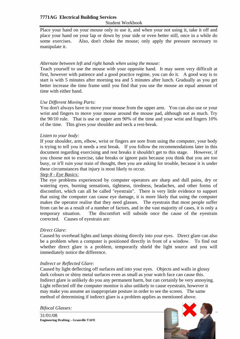
7771AG Electrical Building Services Student Workbook Place your hand on your mouse only to use it, and when your not using it, take it off and place your hand on your lap or down by your side or even better still, once in a while do some exercises. Also, don't choke the mouse; only apply the pressure necessary to manipulate it. Alternate between left and right hands when using the mouse: Teach yourself to use the mouse with your opposite hand. It may seem very difficult at first, however with patience and a good practice regime, you can do it. A good way is to start is with 5 minutes after morning tea and 5 minutes after lunch. Gradually as you get better increase the time frame until you find that you use the mouse an equal amount of time with either hand. Use Different Moving Parts: You don't always have to move your mouse from the upper arm. You can also use or your wrist and fingers to move your mouse around the mouse pad, although not as much. Try the 90/10 rule. That is use or upper arm 90% of the time and your wrist and fingers 10% of the time. This gives your shoulder and neck a rest-break. Listen to your body: If your shoulder, arm, elbow, wrist or fingers are sore from using the computer, your body is trying to tell you it needs a rest break. If you follow the recommendations later in this document regarding exercising and rest breaks it shouldn't get to this stage. However, if you choose not to exercise, take breaks or ignore pain because you think that you are too busy, or it'll ruin your train of thought, then you are asking for trouble, because it is under these circumstances that injury is most likely to occur. Step 8 - Eye Basics: The eye problems experienced by computer operators are sharp and dull pains, dry or watering eyes, burning sensations, tightness, tiredness, headaches, and other forms of discomfort, which can all be called "eyestrain". There is very little evidence to support that using the computer can cause eye damage, it is more likely that using the computer makes the operator realise that they need glasses. The eyestrain that most people suffer from can be as a result of a number of factors, and in the vast majority of cases, it is only a temporary situation. The discomfort will subside once the cause of the eyestrain corrected. Causes of eyestrain are: Direct Glare: Caused by overhead lights and lamps shining directly into your eyes. Direct glare can also be a problem when a computer is positioned directly in front of a window. To find out whether direct glare is a problem, temporarily shield the light source and you will immediately notice the difference.
Indirect or Reflected Glare: Caused by light deflecting off surfaces and into your eyes. Objects and walls in glossy dark colours or shiny metal surfaces even as small as your watch face can cause this. Indirect glare is unlikely do you any permanent harm, but can certainly be very annoying. Light reflected off the computer monitor is also unlikely to cause eyestrain, however it may make you assume an inappropriate posture in order to see the screen. The same method of determining if indirect glare is a problem applies as mentioned above.
31/01/08 Page 11 Bifocal Glasses:
Engineering Drafting – Granville TAFE

7771AG Electrical Building Services Student Workbook If you wear bifocal glasses, you may find that you are tilting your head backward in order to see the screen. This places strain on the neck and shoulders and should be avoided. Bifocals are designed for reading, not computer work and you should see your optometrist about options available to you. In the short term you can place the monitor directly onto the table surface so you are looking down without pushing your head backward to see the screen, but you should see your optometrist soon.
Step 9 – Exercises: Exercising is one of the most effective ways of reducing muscle fatigue and the possibility of injury occurrence when using the computer. Warm-up exercises prepare your body for your next period of work, and Micro-breaks keep the body loose while using the computer. However there are rules to exercising which are:
• Never stretch to the point where you feel pain. • If you have a medical condition or are under going any type of medical
treatment, you must consult your medical practitioner before doing any of these exercises.
• Always apply a slow and gentle stretching action. Exercise 1: Bend your wrist and fingers with your other hand, bending your elbow slightly at the same time, until you feel the stretch over the back of your forearm. Hold the position for 30 seconds.
Exercise 2: Stretch your arm out in front of you with your elbow straight, palm facing away from you (fingers pointing up or down). With your other hand pull your fingers backward until your feel the stretch over the front of your forearm. Hold the position for 30 seconds.
Exercise 3: Tuck your chin down onto your chest and gently turn your head from side to side, keeping your chin on your chest. Do this ten times.
Exercise 4: Turn your head slowly from side to side ten times.
31/01/08 Page 12 Engineering Drafting – Granville TAFE
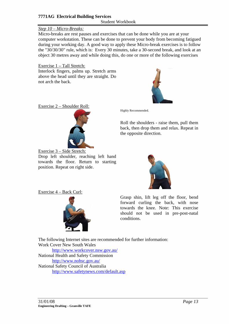
7771AG Electrical Building Services Student Workbook Step 10 – Micro-Breaks: Micro-breaks are rest pauses and exercises that can be done while you are at your computer workstation. These can be done to prevent your body from becoming fatigued during your working day. A good way to apply these Micro-break exercises is to follow the "30/30/30" rule, which is: Every 30 minutes, take a 30-second break, and look at an object 30 metres away and while doing this, do one or more of the following exercises
Exercise 1 – Tall Stretch: Interlock fingers, palms up. Stretch arms above the head until they are straight. Do not arch the back.
Exercise 2 – Shoulder Roll:
Highly Recommended.
Roll the shoulders - raise them, pull them back, then drop them and relax. Repeat in the opposite direction.
Exercise 3 – Side Stretch: Drop left shoulder, reaching left hand towards the floor. Return to starting position. Repeat on right side.
Exercise 4 – Back Curl:
Grasp shin, lift leg off the floor, bend forward curling the back, with nose towards the knee. Note: This exercise should not be used in pre-post-natal conditions.
The following Internet sites are recommended for further information: Work Cover New South Wales
http://www.workcover.nsw.gov.au/National Health and Safety Commission
http://www.nohsc.gov.au/National Safety Council of Australia http://www.safetynews.com/default.asp
31/01/08 Page 13 Engineering Drafting – Granville TAFE

7771AG Electrical Building Services Student Workbook
31/01/08 Page 14 Engineering Drafting – Granville TAFE
TERMINOLOGY Active, Neutral, Ground
The three most common circuit wires. The active brings the current flow in, the neutral returns it to the source, and the ground is a safety route for returning current. The ground and neutral are joined only at the main service panel.
Alternating Current (AC)
A current which periodically changes its direction.
Ampere A unit that measures the strength/rate of flow of electrical current. Buss Bar Separate, metallic strips that extend through the service panel.
Breakers slide onto the "hot" busses and neutral and ground wires screw down in their respective busses.
Circuit Breaker The most common type of "over current protection." A breaker trips when a circuit becomes overloaded or shorts out.
Fuse Removable devices that link a circuit at the fuse box. Fuse connections blow apart and break the circuit if an overload or short occurs.
Hertz Frequency of cycles. Luminaire Ohm A unit that measures the resistance a conductor has to electricity. Service Panel The main circuit breaker panel (or fuse box) where all the circuits tie
into the incoming electrical supply line. Short Circuit When current flows "short" of reaching a device. Caused by a hot
conductor accidentally contacting a neutral or ground. A short circuit is an immediate fault to ground and should always cause the breaker to trip or the fuse to blow.
Switch A device used to open, close or redirect current in an electrical circuit. Switchboard A large single panel, frame, or assembly of panels having switches,
over current, and other protective devices, buses, and usually instruments mounted on the face or back or both. Switchboards are generally accessible from the rear and from the front and are not intended for installation in cabinets.
Transformer An electric device, without moving parts which increases or decreases voltage, i.e. 240V to 12V, eg. electromagnetic induction
Volt A unit that measures the amount of electrical pressure. Watt A unit that measures the amount of electrical power.
7771AG Electrical Building Services Student Workbook
31/01/08 Page 15 Engineering Drafting – Granville TAFE
LESSON 1 - Lighting Diagrams & Symbols Learning Outcomes: On completion of the session, the participants will be able to:
• State the Australian Standards used in the preparation of electrical drawings for Building Services.
• Identify standard electrical lighting symbols used in the preparation of Electrical Building Service drawings.
• State the various line construction types and pen thicknesses that are used in producing Lighting Layout Diagrams.
• List the types of special controls governing lighting systems. • Produce electrical lighting drawings of less complex nature for residential
buildings in accordance with the current Australian Standards. General Information: Licensed electricians perform the wiring of buildings while building codes controls the method of wiring. The electrical power and light drawings are prepared from architectural Floor Plans by the designer or draughtsperson however, specalised electrical contractors can be engaged for the design, and include all data on the position, type of fixture and controls. The circuits can be drawn on the actual Floor Plan for smaller jobs, however, on larger jobs, plans for each floor and drawings showing the position of riser mains, distribution boards and schedules are also prepared. All electricity supplied for domestic power and light in Australia is 240 Volts at 50 Hertz for Single Phase installations and 410 Volts at 50 Hertz for 3-Phase installations. Australian Standards: AS1100 Drawing Practice AS1102 Graphical Symbols for Electrotechnology AS3000 Wiring Rules AS3008.1 Symbols: The symbols used in Australia to produce electrical lighting diagrams mostly conform to those agreed to by the International Electrotechnical Commission. Symbols are drawn using a 0.25 pen.

7771AG Electrical Building Services Student Workbook
Luminaire - Fixed to Wall
Luminaire - 4x40 Watts
Spotlight
Floodlight
Luminaire - Fluorescent Lamp
Signal Lamp
Discharge Lamp
Basic Symbol - Luminaires
4 x 40W
Luminaire for two 40 WattFluorescent Lamps
& Wattage of Fluorescent LampsAlternative Symbol - number and
Fluorescent LampsLuminaire for three 40 Watt
4 x 40W
Luminaire - Emergency
Luminaire - Built in Switch
Lamp with Reflector
Table 1 - Luminaire Symbols
Switch - Single pole pull
Two way switch Push button
Time switch
Intermediate switch
Light dimmertwo pole, three poleSwitches - one way single pole
Luminous push button
Table 2 - Switch Symbols
Symbol Sizes: The sizes of symbols are basically the same. Figure 1 - Basic Symbol Sizes give the sizes for the main components, other components use the same or similar sizes with the same proportions or slightly modified.
Ø3.5
Ø1.5
4 1
10
5
2
Luminaire Switch
Luminaire - Fluorescent
10
5
3
GPO
Board Telephone
3.5
Figure 1 - Basic Symbol Sizes
31/01/08 Page 16 Engineering Drafting – Granville TAFE

7771AG Electrical Building Services Student Workbook Line Construction & Pen Thicknesses: Straight lines are drawn to connect lights to their respective switch positions. The lines are drawn with dashed line construction using a 0.25 pen with the dashes approximately 4mm to 6mm long. The outline or position of all walls, windows, doors and openings representing the building are drawn using 0.25 thick continuous lines. No hatching of walls is required. Lighting Diagrams: Lighting Diagrams show the position of all luminaires (lights) and control devices (switches) marked in their required location using standard drawing symbols. All diagrams are schematic; the position of the luminaires are indicated in their actual position in the building while the lines connecting the luminaires to the switch/s are shown as straight lines.
Luminaire
Switch
Cable
Figure 2 - Luminaire to Switch
The placing of several switches in one area is a common practice so care must be taken when trying to position the switch with it’s associated cable. The switches are placed side-by-side approx 1mm apart as shown in Figure 3 - Arrangement of Switches
Wall
Figure 3 - Arrangement of Switches
Luminaires can be switch on and off at one or more positions therefore, when indicating the cable run between the lights and switches, all switches are connected before indicating the cable run to the lights. Figure 4 shows four lights controlled by 2 switches. In positions 1&3 the lights are turned OFF while in positions 2&4 the lights are turned ON. It can be seen that in positions 1&3, the lines between the 2 switches are not joined therefore the current is cut off from the light while in positions 2&4, the current can pass through the switches because they are joined.
31/01/08 Page 17 Engineering Drafting – Granville TAFE

7771AG Electrical Building Services Student Workbook
Position 1 - Lights OFF Position 2 - Lights ON
Position 4 - Lights ONPosition 3 - Lights OFF
Switch 1
Switch 2
Switch 2
Switch 1
Switch 2
Switch 1
Switch 2
Switch 1
Indication on Drawing
Switch 1
Switch 2
Figure 4
An example of a lighting diagram is shown below.
Figure 5 - Lighting Diagram
Each room should have adequate lighting with the main source of light being controlled by a wall switch located on the latch side of the room’s entrance. Lights in stairways MUST be controlled from both ends. Minimum Lighting Requirements: The purpose of providing lighting is to illuminate rooms and areas to give a safe and relaxed surroundings. The minimum requirement for rooms is 1 luminaire per room up to 14 square meters and an additional luminaire for each additional 9 square meters. All entrances to the dwelling are required to have external lights fitted close to the entrance door. Lights in rooms with multiple entrances should be capable of being operated from
31/01/08 Page 18 Engineering Drafting – Granville TAFE
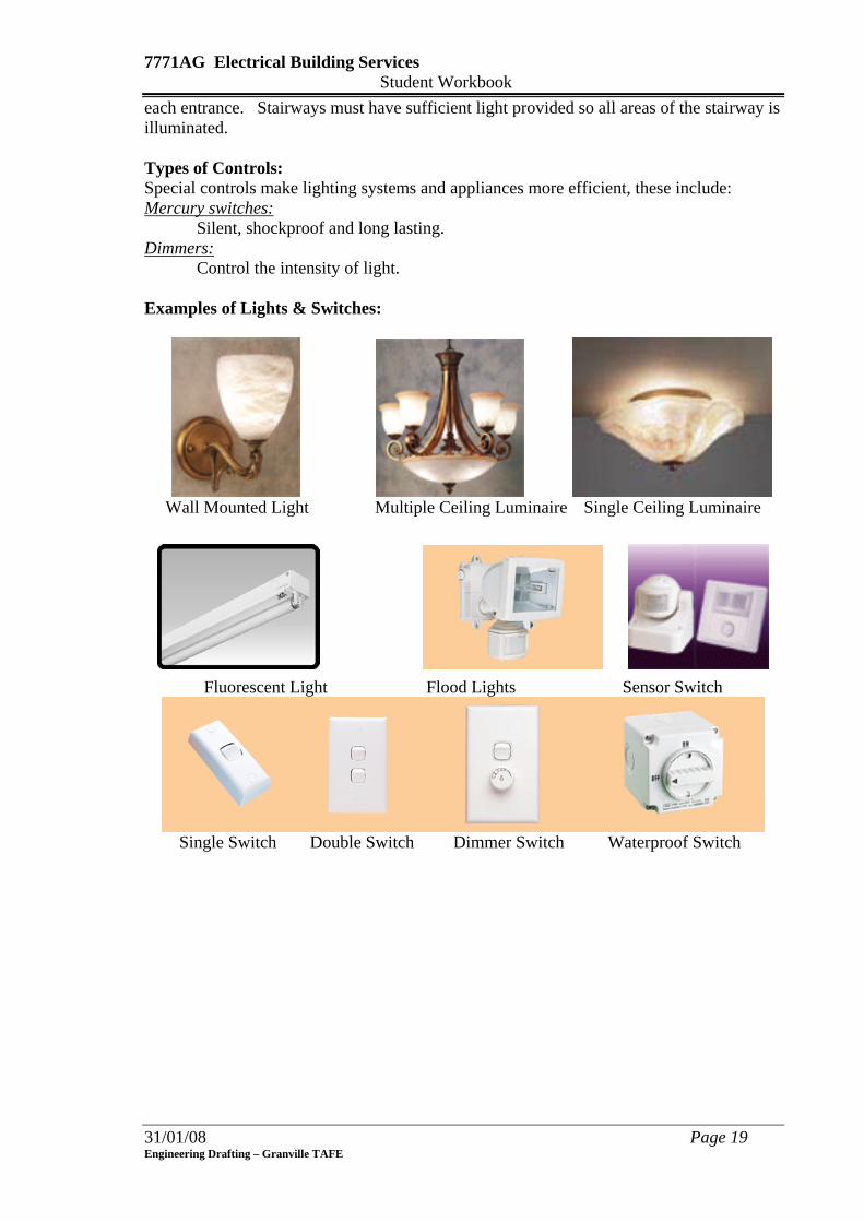
7771AG Electrical Building Services Student Workbook each entrance. Stairways must have sufficient light provided so all areas of the stairway is illuminated. Types of Controls: Special controls make lighting systems and appliances more efficient, these include: Mercury switches:
Silent, shockproof and long lasting. Dimmers: Control the intensity of light. Examples of Lights & Switches:
Wall Mounted Light Multiple Ceiling Luminaire Single Ceiling Luminaire
Fluorescent Light Flood Lights Sensor Switch
Single Switch Double Switch Dimmer Switch Waterproof Switch
31/01/08 Page 19 Engineering Drafting – Granville TAFE
7771AG Electrical Building Services Student Workbook
31/01/08 Page 20 Engineering Drafting – Granville TAFE
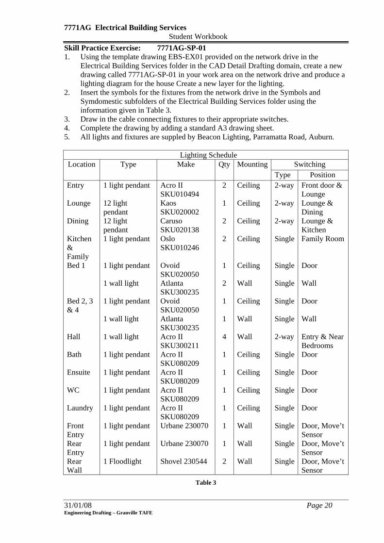
Skill Practice Exercise: 7771AG-SP-01 1. Using the template drawing EBS-EX01 provided on the network drive in the
Electrical Building Services folder in the CAD Detail Drafting domain, create a new drawing called 7771AG-SP-01 in your work area on the network drive and produce a lighting diagram for the house Create a new layer for the lighting.
2. Insert the symbols for the fixtures from the network drive in the Symbols and Symdomestic subfolders of the Electrical Building Services folder using the information given in Table 3.
3. Draw in the cable connecting fixtures to their appropriate switches. 4. Complete the drawing by adding a standard A3 drawing sheet. 5. All lights and fixtures are suppled by Beacon Lighting, Parramatta Road, Auburn. Lighting Schedule Location Type Make Qty Mounting Switching
Type Position Entry 1 light pendant Acro II
SKU010494 2 Ceiling 2-way Front door &
Lounge Lounge 12 light
pendant Kaos SKU020002
1 Ceiling 2-way Lounge & Dining
Dining 12 light pendant
Caruso SKU020138
2 Ceiling 2-way Lounge & Kitchen
Kitchen & Family
1 light pendant Oslo SKU010246
2 Ceiling Single Family Room
Bed 1 1 light pendant 1 wall light
Ovoid SKU020050 Atlanta SKU300235
1 2
Ceiling Wall
Single Single
Door Wall
Bed 2, 3 & 4
1 light pendant 1 wall light
Ovoid SKU020050 Atlanta SKU300235
1 1
Ceiling Wall
Single Single
Door Wall
Hall 1 wall light Acro II SKU300211
4 Wall 2-way Entry & Near Bedrooms
Bath 1 light pendant Acro II SKU080209
1 Ceiling Single Door
Ensuite 1 light pendant Acro II SKU080209
1 Ceiling Single Door
WC 1 light pendant Acro II SKU080209
1 Ceiling Single Door
Laundry 1 light pendant Acro II SKU080209
1 Ceiling Single Door
Front Entry
1 light pendant Urbane 230070 1 Wall Single Door, Move’t Sensor
Rear Entry
1 light pendant Urbane 230070 1 Wall Single Door, Move’t Sensor
Rear Wall
1 Floodlight Shovel 230544 2 Wall Single Door, Move’t Sensor
Table 3
7771AG Electrical Building Services Student Workbook
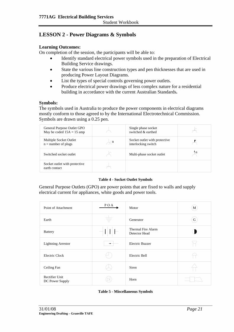
LESSON 2 - Power Diagrams & Symbols Learning Outcomes: On completion of the session, the participants will be able to:
• Identify standard electrical power symbols used in the preparation of Electrical Building Service drawings.
• State the various line construction types and pen thicknesses that are used in producing Power Layout Diagrams.
• List the types of special controls governing power outlets. • Produce electrical power drawings of less complex nature for a residential
building in accordance with the current Australian Standards. Symbols: The symbols used in Australia to produce the power components in electrical diagrams mostly conform to those agreed to by the International Electrotechnical Commission. Symbols are drawn using a 0.25 pen.
Multiple Socket Outlet
Multi-phase socket outlet
May be coded 15A = 15 ampGeneral Purpose Outlet GPO
n
n
n = number of plugs
earth contactSocket outlet with protective
Switched socket outlet
interlocking switchSocket outlet with protective
switched & earthedSingle phase socket
Table 4 - Socket Outlet Symbols
General Purpose Outlets (GPO) are power points that are fixed to walls and supply electrical current for appliances, white goods and power tools.
Generator
Battery
Earth
Lightning Arrestor
Electric Clock
Electric Buzzer
Motor
Thermal Fire AlarmDetector Head
Ceiling Fan
DC Power SupplyRectifier Unit
Point of Attachment M
G
Electric Bell
P O A
Siren
Horn
Table 5 - Miscellaneous Symbols
31/01/08 Page 21 Engineering Drafting – Granville TAFE
7771AG Electrical Building Services Student Workbook
MSBMain Switchboard
Meter Board MB
DSBDistribution Board
CPControl Panel
Exhaust Fan
Cooking Top
Electric Range
Hot Water Service
EF
CT
R
HWS Electric Heater
Garbage Disposal
Air Conditioner
H
GD
AC
Basic Symbol
Table 6 - Appliances & Board Symbols
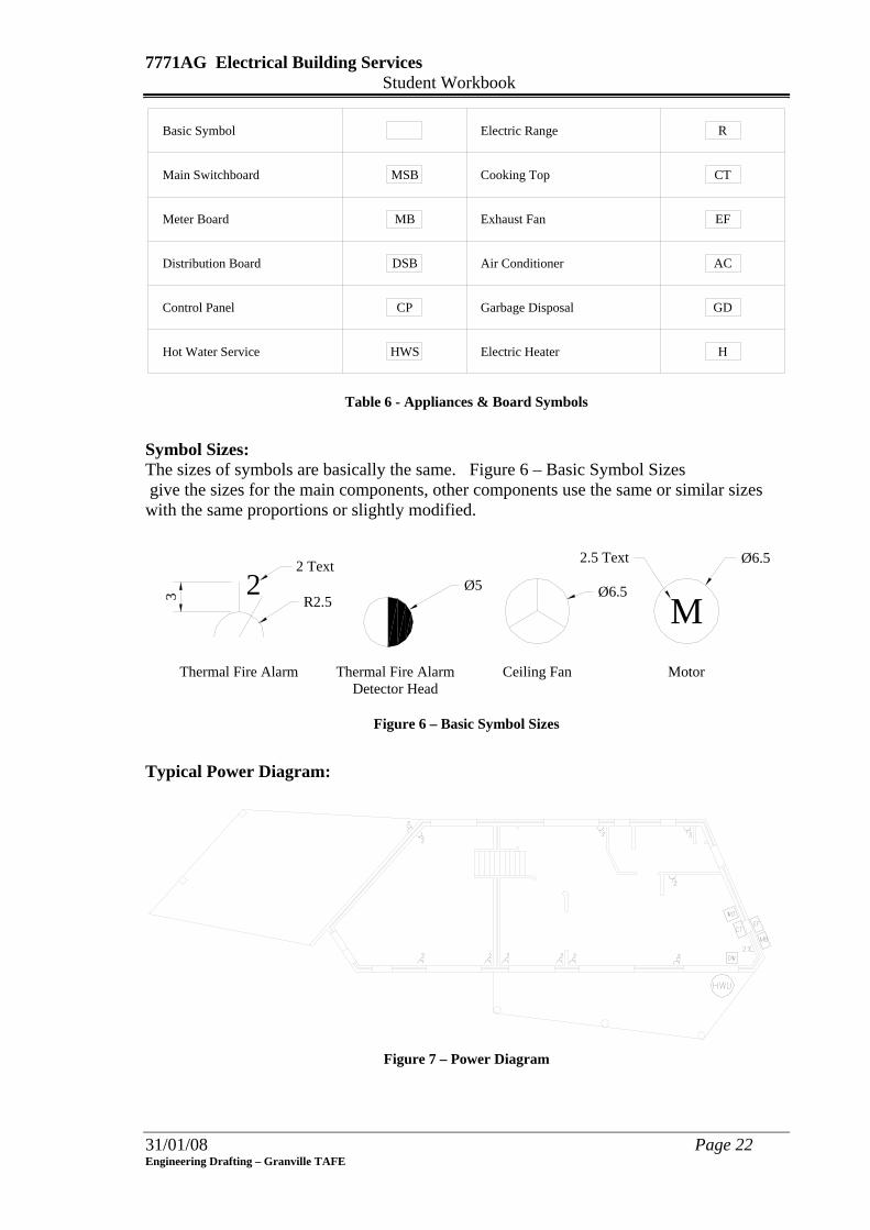
Symbol Sizes: The sizes of symbols are basically the same. Figure 6 – Basic Symbol Sizes give the sizes for the main components, other components use the same or similar sizes with the same proportions or slightly modified.
MotorThermal Fire AlarmDetector Head
Ceiling Fan
M
Ø6.52.5 Text
Ø5R2.5
Thermal Fire Alarm
23
2 Text
Ø6.5
Figure 6 – Basic Symbol Sizes
Typical Power Diagram:
Figure 7 – Power Diagram
31/01/08 Page 22 Engineering Drafting – Granville TAFE

7771AG Electrical Building Services Student Workbook Power Outlets in Domestic Installations: The number of positions of power outlets varies with the use of each room. The high usage of new electrical appliances in today’s society requires a greater number of power outlets than in previous years. Prior to the 1960’s, most Bedrooms had no power points, or were restricted to the Main Bedroom; today a Bedroom needs a minimum of 1 double GPO. Electrical equipment such as hairdryers, heaters, fans, computers, games, clock radios, entertainment systems (radio, television, video) are standard accessories in Bedrooms so sufficient GPO’s must be provided to eliminate the use of double adaptors which can lead to overloading of circuits and start fires. Stoves, Wall Ovens, and Cooktops have their own circuits back to the Meter Board. Table 7 indicates the typical number of outlets for various rooms in the average dwelling. The total wattage per power circuit is 4800 Watts.
Room Number of Outlets
Number of Circuits
Ampere Appliances Operated
Kitchen 6 2 1
2 2 1
10
15 20
Refrigerator, Freezer Dishwasher, Range hood, Garbage Disposal. Wall Oven, Cooktop. Stove.
Lounge Room 4 2 10 Television, Video, Stereo, Standing Lamps,
Family Room 4 2 10 Television, Video, Stereo, Games, Standing Lamps, Telephone, Computer, Musical Instruments.
Bedrooms 2 1 10 Radio, Alarm Clocks, Hair dryers, Computers, Games, Water beds, Bed Lamps
Office & Study 4 2 10 Computer, Phone, Facsimile, Radio, Printer, Scanner, Fan
Garage 4 1
2 1
10 15
Drills, Machinery, Radio Lathes, Electric Welder
Air conditioner and/or heater
1 1 15
Hall, Passage 1 1 10 Lamps, Phone Laundry 2
1 1 1
10 15
Washing Machine, Clothes Dryer Hot Water Unit
Table 7 Most electrical appliances in a residential dwelling operated using 10-ampere; heavier appliances such as air-conditioners, heaters, welding machines, engineering machinery, stoves require 15-ampere power to operate.
Single GPO Double GPO Weatherproof GPO
31/01/08 Page 23 Engineering Drafting – Granville TAFE
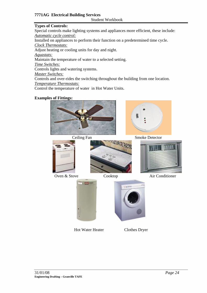
7771AG Electrical Building Services Student Workbook Types of Controls: Special controls make lighting systems and appliances more efficient, these include: Automatic cycle control: Installed on appliances to perform their function on a predetermined time cycle. Clock Thermostats: Adjust heating or cooling units for day and night. Aquastats: Maintain the temperature of water to a selected setting. Time Switches: Controls lights and watering systems. Master Switches: Controls and over-rides the switching throughout the building from one location. Temperature Thermostats: Control the temperature of water in Hot Water Units. Examples of Fittings:
Ceiling Fan Smoke Detector
Oven & Stove Cooktop Air Conditioner
Hot Water Heater Clothes Dryer
31/01/08 Page 24 Engineering Drafting – Granville TAFE

7771AG Electrical Building Services Student Workbook
31/01/08 Page 25 Engineering Drafting – Granville TAFE
Skill Practice Exercise: 7771AG-SP-01 (extension) 1. Open drawing 7771AG-SP-01 in your work area and create a new layer to add the
power symbols. 2. Insert the power symbols from the network drive in the Electrical Building Services
domain of the CAD Drafting folder using the information given in Table 8 to suit Figure 7.
Item Appliance Make Wattage Mounting Position 1 – 2 Double GPO Wattmore B7 2000 300mm above bench 3 – 15 Double GPO Wattmore B7 2000 300mm above floor 16 – 18 Double GPO Wattmore B7 2000 1200mm above floor
19 Single GPO Wattmore B6 1000 750 above floor 20 Single GPO Wattmore B6 1000 2000 above floor
21 – 22 Single GPO Wattmore B6 1000 300mm above bench 23 – 27 Ceiling Fan Cascade 210627 Center of ceiling
28 Buzzer Left of front entry door 29 Bell 2100mm above floor 30 Electric Clock 2100mm above floor 31 Cooktop Chef A3245 5950 32 Range hood Robin Hood 1000 Over cooktop 33 Dishwasher ASEA 1800 1000 Under sink 34 Wall Oven Chef WO2187 35 Meter Box
36 – 38 Exhaust Fan Simms 1778 85 Ceiling over Vanity Table 8
Figure 8
4
3
5
6 7 8
9
1011
12
1317
1614
1518
1 2
19
20
21
22
23 24 25
26
27
29
30
28
3132
33
35
34
36
37
38
7771AG Electrical Building Services Student Workbook
Lesson 3 - Telecommunication Symbols Learning Outcomes: On completion of the session, the participants will be able to:
• Identify standard electrical telecommunication symbols used in the preparation of Electrical Building Service drawings.
• Produce drawings of less complex nature using electrical telecommunication symbols for a residential building in accordance with the current Australian Standards.
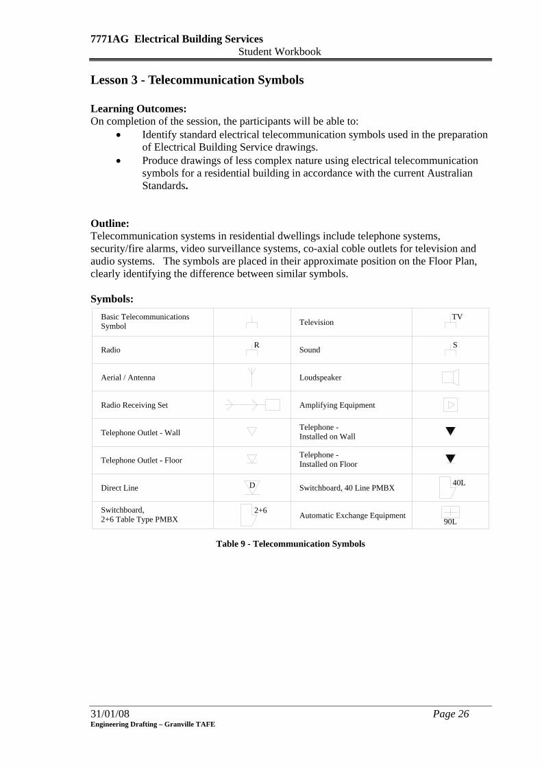
Outline: Telecommunication systems in residential dwellings include telephone systems, security/fire alarms, video surveillance systems, co-axial coble outlets for television and audio systems. The symbols are placed in their approximate position on the Floor Plan, clearly identifying the difference between similar symbols. Symbols:
LoudspeakerAerial / Antenna
Radio
Radio Receiving Set
Telephone Outlet - Wall
Television
Sound
Direct Line
Automatic Exchange Equipment
Switchboard, 40 Line PMBX
SymbolBasic Telecommunications
Amplifying Equipment
R S
TV
Telephone -Installed on Wall
Installed on FloorTelephone -
Telephone Outlet - Floor
D
90L2+6
40L
2+6 Table Type PMBXSwitchboard,
Table 9 - Telecommunication Symbols
31/01/08 Page 26 Engineering Drafting – Granville TAFE
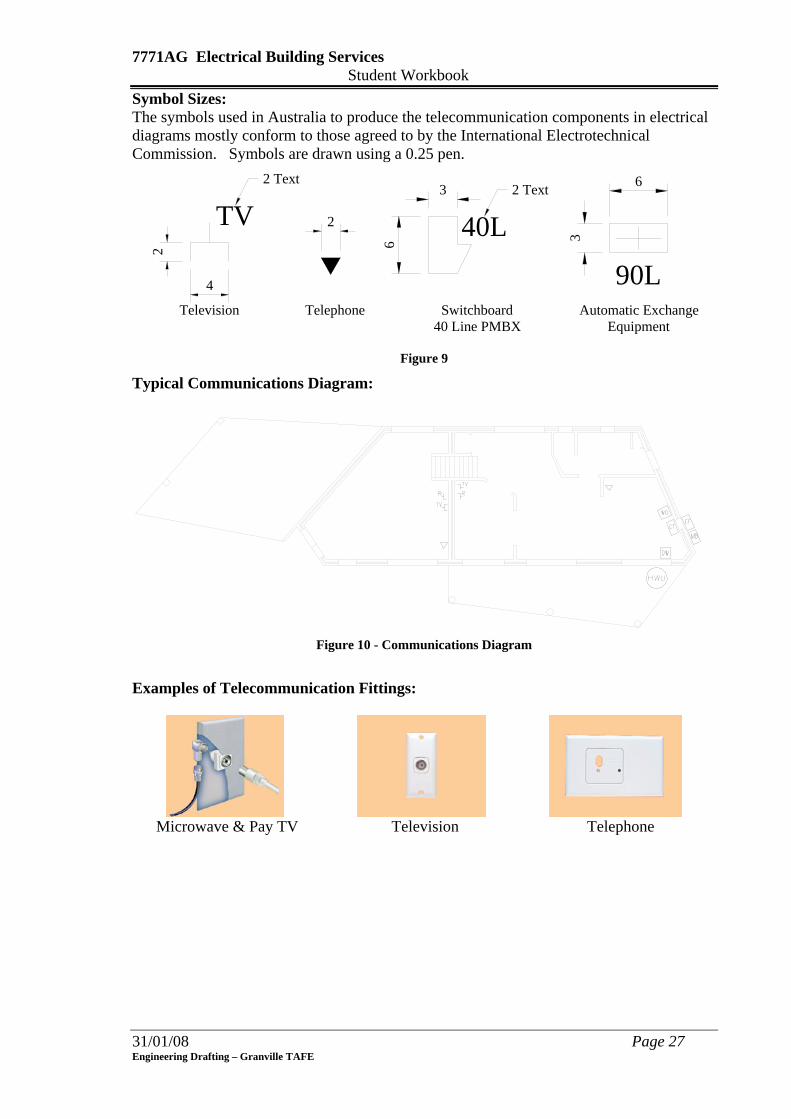
7771AG Electrical Building Services Student Workbook Symbol Sizes: The symbols used in Australia to produce the telecommunication components in electrical diagrams mostly conform to those agreed to by the International Electrotechnical Commission. Symbols are drawn using a 0.25 pen.
Telephone SwitchboardTelevision
TV2 Text
2
4
2 40L2 Text
40 Line PMBX
90L
6
36
3
Automatic ExchangeEquipment
Figure 9
Typical Communications Diagram:
Figure 10 - Communications Diagram
Examples of Telecommunication Fittings:
Microwave & Pay TV Television Telephone
31/01/08 Page 27 Engineering Drafting – Granville TAFE
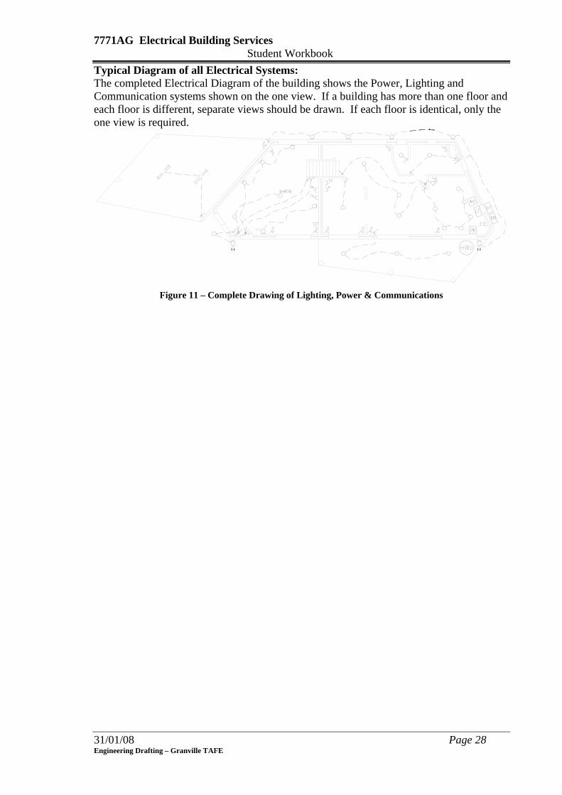
7771AG Electrical Building Services Student Workbook Typical Diagram of all Electrical Systems: The completed Electrical Diagram of the building shows the Power, Lighting and Communication systems shown on the one view. If a building has more than one floor and each floor is different, separate views should be drawn. If each floor is identical, only the one view is required.
Figure 11 – Complete Drawing of Lighting, Power & Communications
31/01/08 Page 28 Engineering Drafting – Granville TAFE

7771AG Electrical Building Services Student Workbook Skill Practice Exercise: 7771AG-SP-01 (extension)
1. Open drawing 7771AG-SP-01 in your work area and create a new layer to add the communication symbols.
2. Insert the power symbols from the Electrical Building services folder in the CAD Drafting domain on the network drive using the information in Table 10 to suit Figure 9.
Item Description 1 – 4 Television 5 – 6 Radio
7 Sound 8 Amplifying Equipment
9 – 12 Surround Sound System 13 Wall Mounted Telephone
14 – 17 Floor Telephone Outlet 18 – 22 Floor Telephone/Internet Outlet
23 Aerial Table 10
14 13
23
22
8
6
2
21
19
73
17
20
16
12
1110
1
15
9
1854
Figure 12
31/01/08 Page 29 Engineering Drafting – Granville TAFE
7771AG Electrical Building Services Student Workbook
31/01/08 Page 30 Engineering Drafting – Granville TAFE
LESSON 4 – Electrical Schedules Learning Outcomes: On completion of the session, the participants will be able to:
• Explain the use of Electrical Schedules on electrical building service drawings. • Determine to number of columns required to produce a schedule of electrical
fittings on a drawing. • Produce an Electrical Schedule on an electrical building service drawing.
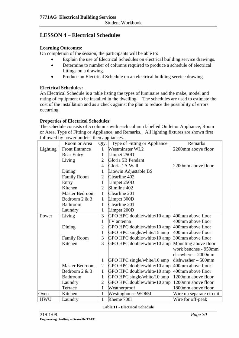
Electrical Schedules: An Electrical Schedule is a table listing the types of luminaire and the make, model and rating of equipment to be installed in the dwelling. The schedules are used to estimate the cost of the installation and as a check against the plan to reduce the possibility of errors occurring. Properties of Electrical Schedules: The schedule consists of 5 columns with each column labelled Outlet or Appliance, Room or Area, Type of Fitting or Appliance, and Remarks. All lighting fixtures are shown first followed by power outlets, then appliances.
Room or Area Qty. Type of Fitting or Appliance Remarks Lighting Front Entrance 1 Westminster WL2 2200mm above floor Rear Entry 1 Limpet 250D Living 2
4 Gloria 5B Pendant Gloria 1A Wall
2200mm above floor
Dining 1 Litewin Adjustable BS Family Room 2 Clearline 402 Entry 1 Limpet 250D Kitchen 2 Slimline 402 Master Bedroom 1 Clearline 201 Bedroom 2 & 3 1 Limpet 300D Bathroom 1 Clearline 201 Laundry 1 Limpet 200D Power Living 3
1 GPO HPC double/white/10 amp TV antenna
400mm above floor 400mm above floor
Dining 2 1
GPO HPC double/white/10 amp GPO HPC single/white/15 amp
400mm above floor 400mm above floor
Family Room 3 GPO HPC double/white/10 amp 300mm above floor Kitchen 3
1
GPO HPC double/white/10 amp
GPO HPC single/white/10 amp
Mounting above floor work benches - 950mm elsewhere – 2000mm dishwasher – 500mm
Master Bedroom 2 GPO HPC double/white/10 amp 400mm above floor Bedroom 2 & 3 1 GPO HPC double/white/10 amp 400mm above floor Bathroom 1 GPO HPC single/white/10 amp 1200mm above floor Laundry 2 GPO HPC double/white/10 amp 1200mm above floor Terrace 1 Weatherproof 1800mm above floor
Oven Kitchen 1 Westinghouse WO65L Wire on separate circuit HWU Laundry 1 Rheme 700l Wire for off-peak
Table 11 - Electrical Schedule
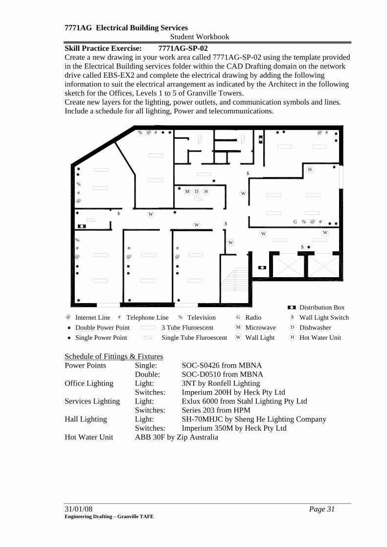
7771AG Electrical Building Services Student Workbook Skill Practice Exercise: 7771AG-SP-02 Create a new drawing in your work area called 7771AG-SP-02 using the template provided in the Electrical Building services folder within the CAD Drafting domain on the network drive called EBS-EX2 and complete the electrical drawing by adding the following information to suit the electrical arrangement as indicated by the Architect in the following sketch for the Offices, Levels 1 to 5 of Granville Towers. Create new layers for the lighting, power outlets, and communication symbols and lines. Include a schedule for all lighting, Power and telecommunications.
W
W
W W
W
W
Double Power PointSingle Power Point Single Tube Fluroescent W Wall Light
3 Tube Fluroescent
M D H
H
M Microwave D
H
DishwasherHot Water Unit
$
$
$
$
#
@
@
#
#
@ @
###
#
@ @
@%
%
%
%
G
$ Wall Light SwitchRadioGTelevision%Internet Line@ Telephone Line#
Distribution Box
Schedule of Fittings & Fixtures Power Points Single: SOC-S0426 from MBNA Double: SOC-D0510 from MBNA Office Lighting Light: 3NT by Ronfell Lighting
Switches: Imperium 200H by Heck Pty Ltd Services Lighting Light: Exlux 6000 from Stahl Lighting Pty Ltd Switches: Series 203 from HPM Hall Lighting Light: SH-70MHJC by Sheng He Lighting Company Switches: Imperium 350M by Heck Pty Ltd Hot Water Unit ABB 30F by Zip Australia
31/01/08 Page 31 Engineering Drafting – Granville TAFE

7771AG Electrical Building Services Student Workbook Skill Practice Exercise: 7771AG-SP-03 Create a new drawing in your work area called 7771AG-SP-03 using the template provided in the Electrical Building services folder within the CAD Drafting domain on the network drive called EBS-EX3 and complete the electrical drawing by adding the following information to suit the electrical arrangement as indicated by the Architect in the following sketch for the Basement Level of Granville Towers. Create new layers for the lighting, power outlets, and communication symbols and lines. Include a schedule for all lighting, power and telecommunications.
Double Power PointFlood Light3 Tube FluroescentM Main SwitchboardInternal Light Movement Sensor%
Telephone#
Distribution Board
#
@
%%
%
M
Flood Light Movement Sensor@
Light Zone 1Light Zone 2
Light Zone 3
Time Switch
60W LightAll Fluorescent Lights are controlled by Master Switches in the Switchboard Room.
Schedule of Fittings & Fixtures Power Points Single: 240S-H1 from Elenco Double: 240D-H2 from Elenco Car Park Lighting Light: 3NT by Heltley Lighting Movement Sensors Floodlights: IR34 by Olathe Car Paring: RG-67h by Pro Tech Services Services Lighting Light: Exlux 3000 from Stahl Lighting Pty Ltd Switches: Series 111 from HPM
31/01/08 Page 32 Engineering Drafting – Granville TAFE
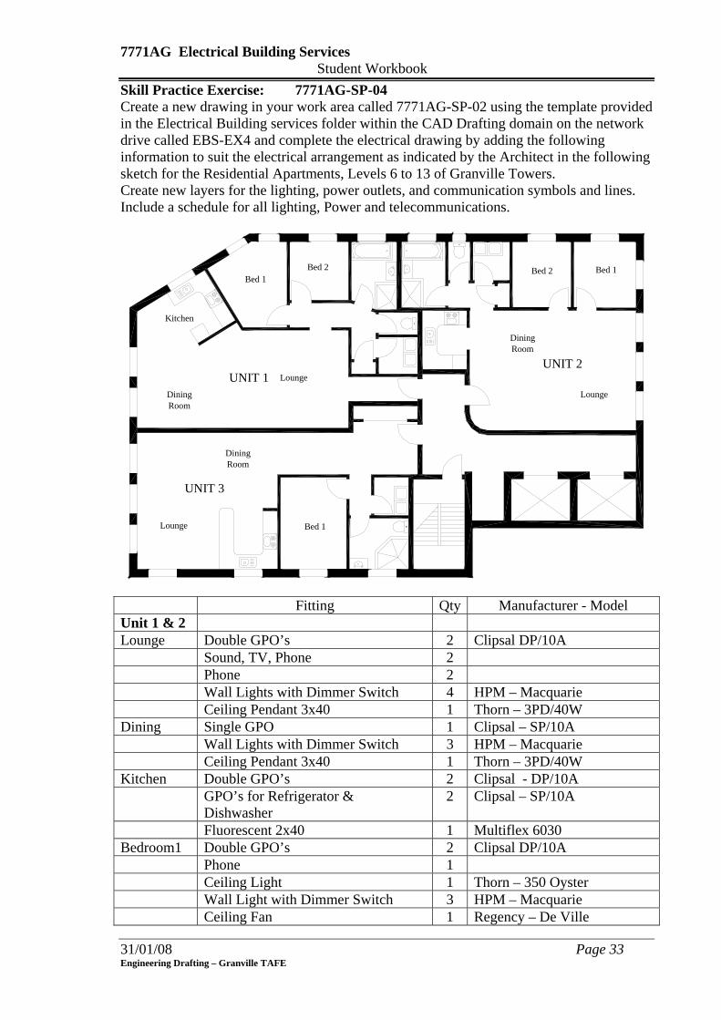
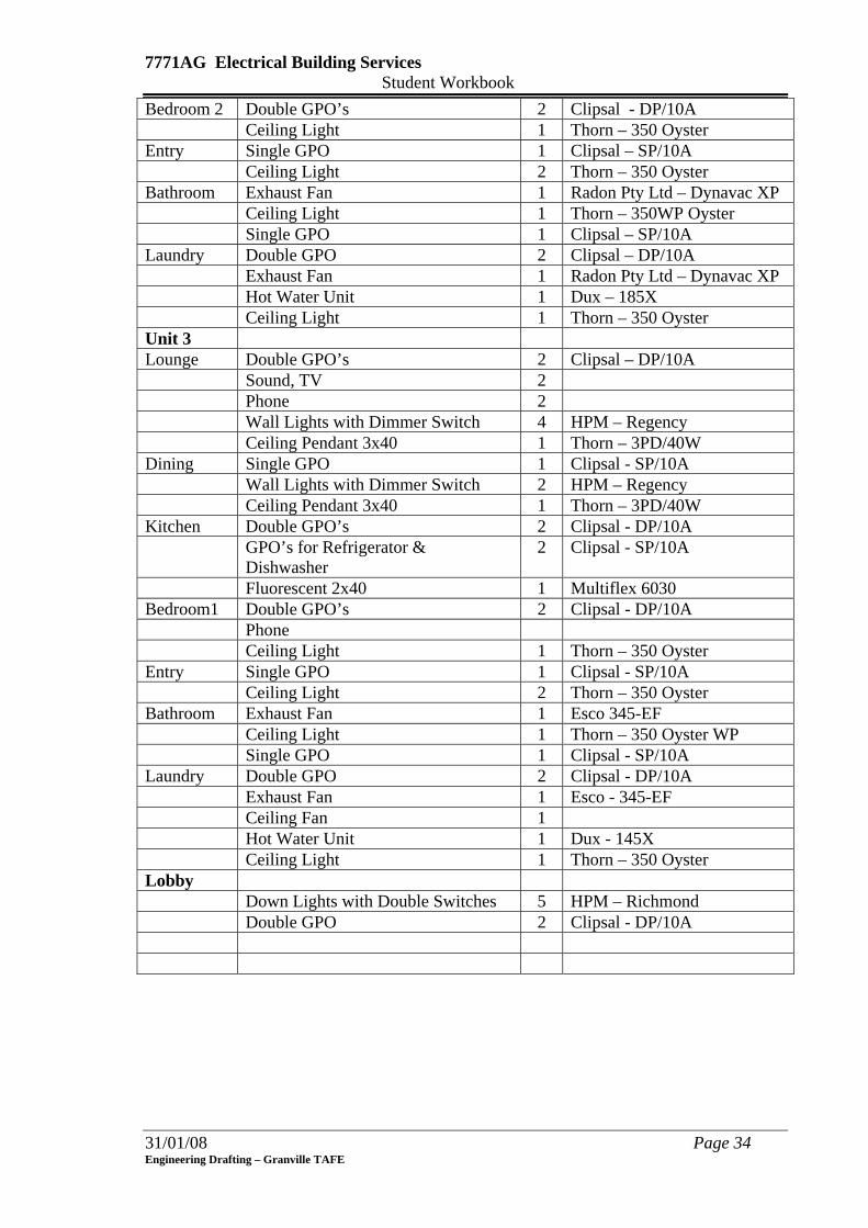
7771AG Electrical Building Services Student Workbook Skill Practice Exercise: 7771AG-SP-04 Create a new drawing in your work area called 7771AG-SP-02 using the template provided in the Electrical Building services folder within the CAD Drafting domain on the network drive called EBS-EX4 and complete the electrical drawing by adding the following information to suit the electrical arrangement as indicated by the Architect in the following sketch for the Residential Apartments, Levels 6 to 13 of Granville Towers. Create new layers for the lighting, power outlets, and communication symbols and lines. Include a schedule for all lighting, Power and telecommunications.
UNIT 1UNIT 2
UNIT 3
Lounge
Kitchen
Bed 1Bed 2
DiningRoom
DiningRoom
DiningRoom
Lounge
Lounge
Bed 1
Bed 1
Bed 2
Fitting Qty Manufacturer - Model Unit 1 & 2 Lounge Double GPO’s 2 Clipsal DP/10A Sound, TV, Phone 2 Phone 2 Wall Lights with Dimmer Switch 4 HPM – Macquarie Ceiling Pendant 3x40 1 Thorn – 3PD/40W Dining Single GPO 1 Clipsal – SP/10A Wall Lights with Dimmer Switch 3 HPM – Macquarie Ceiling Pendant 3x40 1 Thorn – 3PD/40W Kitchen Double GPO’s 2 Clipsal - DP/10A GPO’s for Refrigerator &
Dishwasher 2 Clipsal – SP/10A
Fluorescent 2x40 1 Multiflex 6030 Bedroom1 Double GPO’s 2 Clipsal DP/10A Phone 1 Ceiling Light 1 Thorn – 350 Oyster Wall Light with Dimmer Switch 3 HPM – Macquarie Ceiling Fan 1 Regency – De Ville
31/01/08 Page 33 Engineering Drafting – Granville TAFE
7771AG Electrical Building Services Student Workbook
31/01/08 Page 34 Engineering Drafting – Granville TAFE
Bedroom 2 Double GPO’s 2 Clipsal - DP/10A Ceiling Light 1 Thorn – 350 Oyster Entry Single GPO 1 Clipsal – SP/10A Ceiling Light 2 Thorn – 350 Oyster Bathroom Exhaust Fan 1 Radon Pty Ltd – Dynavac XP Ceiling Light 1 Thorn – 350WP Oyster Single GPO 1 Clipsal – SP/10A Laundry Double GPO 2 Clipsal – DP/10A Exhaust Fan 1 Radon Pty Ltd – Dynavac XP Hot Water Unit 1 Dux – 185X Ceiling Light 1 Thorn – 350 Oyster Unit 3 Lounge Double GPO’s 2 Clipsal – DP/10A Sound, TV 2 Phone 2 Wall Lights with Dimmer Switch 4 HPM – Regency Ceiling Pendant 3x40 1 Thorn – 3PD/40W Dining Single GPO 1 Clipsal - SP/10A Wall Lights with Dimmer Switch 2 HPM – Regency Ceiling Pendant 3x40 1 Thorn – 3PD/40W Kitchen Double GPO’s 2 Clipsal - DP/10A GPO’s for Refrigerator &
Dishwasher 2 Clipsal - SP/10A
Fluorescent 2x40 1 Multiflex 6030 Bedroom1 Double GPO’s 2 Clipsal - DP/10A Phone Ceiling Light 1 Thorn – 350 Oyster Entry Single GPO 1 Clipsal - SP/10A Ceiling Light 2 Thorn – 350 Oyster Bathroom Exhaust Fan 1 Esco 345-EF Ceiling Light 1 Thorn – 350 Oyster WP Single GPO 1 Clipsal - SP/10A Laundry Double GPO 2 Clipsal - DP/10A Exhaust Fan 1 Esco - 345-EF Ceiling Fan 1 Hot Water Unit 1 Dux - 145X Ceiling Light 1 Thorn – 350 Oyster Lobby Down Lights with Double Switches 5 HPM – Richmond Double GPO 2 Clipsal - DP/10A
7771AG Electrical Building Services Student Workbook
31/01/08 Page 35 Engineering Drafting – Granville TAFE
LESSON 5 Assessment Test 1: Exercise
Complete all Skill Practice Exercises to 7771AG-SP-04
7771AG Electrical Building Services Student Workbook
LESSON 6 - Riser Diagrams Learning Outcomes: On completion of the session, the participants will be able to:
• Describe the purpose of providing a riser diagram on an electrical drawing. • State the pen sizes and line constructions use when producing a riser diagram. • Identify the labels and abbreviations used on riser diagrams. • Produce a drawing containing a riser diagram.
Riser Diagrams: Electrical Riser Diagrams show the distribution of electricity throughout a multi-storey building. The electricity arrives from the mains, to the switchboard or meter board, from where the electricity is then distributed through sub-circuits. The electricity is then dispersed to distribution boxes on the various floors. Riser diagrams are elevations of the building that show the distribution of the electricity. The elevations are drawn to scale but the actual run of the cables, fittings and boxes are schematic and not drawn to scale. The drawings should be kept simple with all lines drawn either vertical or horizontal. In multi storey buildings, the electrical installation can be divided into three sections:
• Incoming consumer mains to the switchboard. • Sub-mains systems. • Electrical installation.
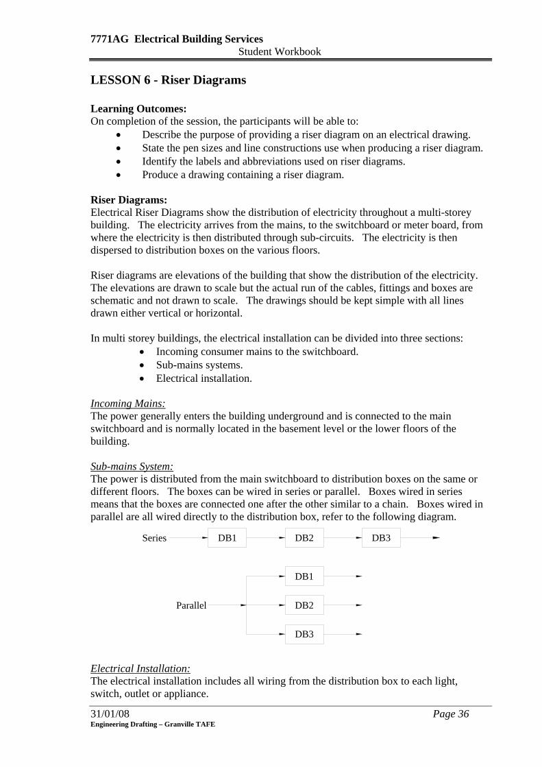
Incoming Mains: The power generally enters the building underground and is connected to the main switchboard and is normally located in the basement level or the lower floors of the building. Sub-mains System: The power is distributed from the main switchboard to distribution boxes on the same or different floors. The boxes can be wired in series or parallel. Boxes wired in series means that the boxes are connected one after the other similar to a chain. Boxes wired in parallel are all wired directly to the distribution box, refer to the following diagram.
DB1 DB2 DB3
DB1
DB2
DB3
Parallel
Series
Electrical Installation: The electrical installation includes all wiring from the distribution box to each light, switch, outlet or appliance.
31/01/08 Page 36 Engineering Drafting – Granville TAFE

7771AG Electrical Building Services Student Workbook
TR
DB1
DB3A
DB4A
DB5
DB
DB3B
DB4B
DB2
DBB
DBEL
M S B1 2 3 4 5
6
GR. FL
1st FL
2nd FL
3rd FL
4th Fl
5th FL
Roof
Basement
Consumer Mains
Figure 13 - Typical Riser Diagram
The schedule for Figure 10 would be shown as follows:
Floor No of Boards Riser No Title Basement 1 6 DDB
Ground Floor 1 1 DB1 1st 1 4 DB2 2nd 2 2 & 4 DB3A & DB3B 3rd 2 2 & 4 DB4A & DB4B 4th 1 3 DB5 5th 2 3 & 5 DB & DBELEV
Pen Thicknesses & Line Construction: All lines representing the electrical risers are produced using a 1mm wide continuous line; floor lines and walls are drawn using a 0.25mm line while equipment (distribution boards, switchboards, power equipment) is drawn as rectangles to the approximate scale but should be of sufficient size to comfortably fit any lettering. All equipment is labelled according to the schedule and floors identified. Typical Abbreviations: Distribution Board DBn DBA, Dbelev, DB2/A, DB2-2 Main Switchboard MSB Meter Box MBn MB1, MB3/A, MB6-1 Transformer TRn TR1, TRA Emergency Switchboard ESB n = Floor Identification and/or Item Number
31/01/08 Page 37 Engineering Drafting – Granville TAFE
7771AG Electrical Building Services Student Workbook
31/01/08 Page 38 Engineering Drafting – Granville TAFE
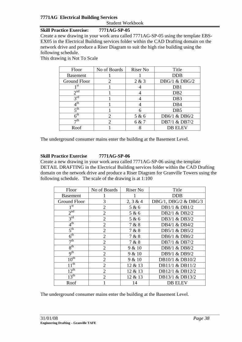
Skill Practice Exercise: 7771AG-SP-05 Create a new drawing in your work area called 7771AG-SP-05 using the template EBS-EX05 in the Electrical Building services folder within the CAD Drafting domain on the network drive and produce a Riser Diagram to suit the high rise building using the following schedule. This drawing is Not To Scale
Floor No of Boards Riser No Title Basement 1 1 DDB
Ground Floor 2 2 & 3 DBG/1 & DBG/2 1st 1 4 DB1 2nd 1 4 DB2 3rd 1 4 DB3 4th 1 4 DB4 5th 1 6 DB5 6th 2 5 & 6 DB6/1 & DB6/2 7th 2 6 & 7 DB7/1 & DB7/2
Roof 1 8 DB ELEV The underground consumer mains enter the building at the Basement Level. Skill Practice Exercise 7771AG-SP-06 Create a new drawing in your work area called 7771AG-SP-06 using the template DETAIL DRAFTING in the Electrical Building services folder within the CAD Drafting domain on the network drive and produce a Riser Diagram for Granville Towers using the following schedule. The scale of the drawing is at 1:100
Floor No of Boards Riser No Title Basement 1 1 DDB
Ground Floor 3 2, 3 & 4 DBG/1, DBG/2 & DBG/3 1st 2 5 & 6 DB1/1 & DB1/2 2nd 2 5 & 6 DB2/1 & DB2/2 3rd 2 5 & 6 DB3/1 & DB3/2 4th 2 7 & 8 DB4/1 & DB4/2 5th 2 7 & 8 DB5/1 & DB5/2 6th 2 7 & 8 DB6/1 & DB6/2 7th 2 7 & 8 DB7/1 & DB7/2 8th 2 9 & 10 DB8/1 & DB8/2 9th 2 9 & 10 DB9/1 & DB9/2 10th 2 9 & 10 DB10/1 & DB10/2 11th 2 12 & 13 DB11/1 & DB11/2 12th 2 12 & 13 DB12/1 & DB12/2 13th 2 12 & 13 DB13/1 & DB13/2 Roof 1 14 DB ELEV
The underground consumer mains enter the building at the Basement Level.
7771AG Electrical Building Services Student Workbook
31/01/08 Page 39 Engineering Drafting – Granville TAFE
7771AG Electrical Building Services Student Workbook
LESSON 7 - Switchboard Layouts Learning Outcomes: On completion of the session, the participants will be able to:
• Define the difference between a meter box and distribution board. • List two types of switchboard used in building construction. • List seven (7) fittings used on domestic meter boxes. • List four (4) types of commercial switchboard. • Produce a drawing of a domestic meter box.
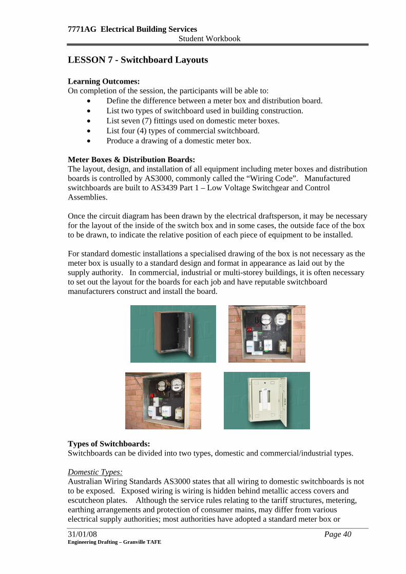
Meter Boxes & Distribution Boards: The layout, design, and installation of all equipment including meter boxes and distribution boards is controlled by AS3000, commonly called the “Wiring Code”. Manufactured switchboards are built to AS3439 Part 1 – Low Voltage Switchgear and Control Assemblies. Once the circuit diagram has been drawn by the electrical draftsperson, it may be necessary for the layout of the inside of the switch box and in some cases, the outside face of the box to be drawn, to indicate the relative position of each piece of equipment to be installed. For standard domestic installations a specialised drawing of the box is not necessary as the meter box is usually to a standard design and format in appearance as laid out by the supply authority. In commercial, industrial or multi-storey buildings, it is often necessary to set out the layout for the boards for each job and have reputable switchboard manufacturers construct and install the board.
Types of Switchboards: Switchboards can be divided into two types, domestic and commercial/industrial types. Domestic Types: Australian Wiring Standards AS3000 states that all wiring to domestic switchboards is not to be exposed. Exposed wiring is wiring is hidden behind metallic access covers and escutcheon plates. Although the service rules relating to the tariff structures, metering, earthing arrangements and protection of consumer mains, may differ from various electrical supply authorities; most authorities have adopted a standard meter box or
31/01/08 Page 40 Engineering Drafting – Granville TAFE
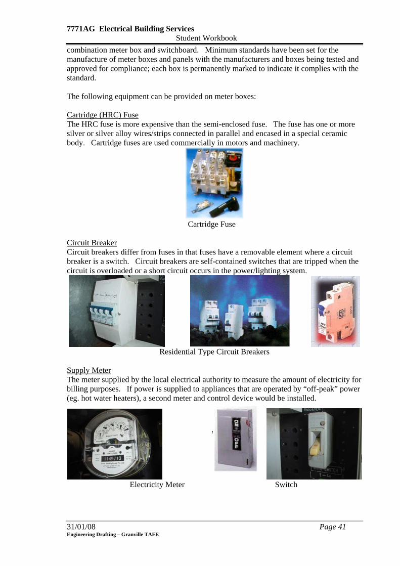
7771AG Electrical Building Services Student Workbook combination meter box and switchboard. Minimum standards have been set for the manufacture of meter boxes and panels with the manufacturers and boxes being tested and approved for compliance; each box is permanently marked to indicate it complies with the standard. The following equipment can be provided on meter boxes: Cartridge (HRC) Fuse The HRC fuse is more expensive than the semi-enclosed fuse. The fuse has one or more silver or silver alloy wires/strips connected in parallel and encased in a special ceramic body. Cartridge fuses are used commercially in motors and machinery.
Cartridge Fuse
Circuit Breaker Circuit breakers differ from fuses in that fuses have a removable element where a circuit breaker is a switch. Circuit breakers are self-contained switches that are tripped when the circuit is overloaded or a short circuit occurs in the power/lighting system.
Residential Type Circuit Breakers
Supply Meter The meter supplied by the local electrical authority to measure the amount of electricity for billing purposes. If power is supplied to appliances that are operated by “off-peak” power (eg. hot water heaters), a second meter and control device would be installed.
Electricity Meter Switch
31/01/08 Page 41 Engineering Drafting – Granville TAFE
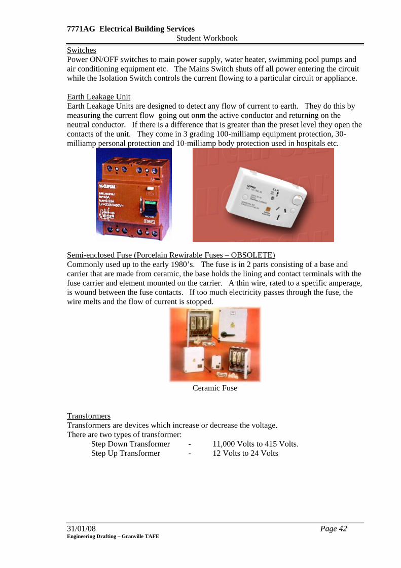
7771AG Electrical Building Services Student Workbook Switches Power ON/OFF switches to main power supply, water heater, swimming pool pumps and air conditioning equipment etc. The Mains Switch shuts off all power entering the circuit while the Isolation Switch controls the current flowing to a particular circuit or appliance. Earth Leakage Unit Earth Leakage Units are designed to detect any flow of current to earth. They do this by measuring the current flow going out onm the active conductor and returning on the neutral conductor. If there is a difference that is greater than the preset level they open the contacts of the unit. They come in 3 grading 100-milliamp equipment protection, 30-milliamp personal protection and 10-milliamp body protection used in hospitals etc.
Semi-enclosed Fuse (Porcelain Rewirable Fuses – OBSOLETE) Commonly used up to the early 1980’s. The fuse is in 2 parts consisting of a base and carrier that are made from ceramic, the base holds the lining and contact terminals with the fuse carrier and element mounted on the carrier. A thin wire, rated to a specific amperage, is wound between the fuse contacts. If too much electricity passes through the fuse, the wire melts and the flow of current is stopped.
Ceramic Fuse
Transformers Transformers are devices which increase or decrease the voltage. There are two types of transformer:
Step Down Transformer - 11,000 Volts to 415 Volts. Step Up Transformer - 12 Volts to 24 Volts
31/01/08 Page 42 Engineering Drafting – Granville TAFE

7771AG Electrical Building Services Student Workbook
General Purpose Small Power Rectifiers Rectifiers convert Alternating Current (AC) to Direct Current (DC).
Low Power Rectifier High Power rectifier
Typical Dimensions of Switchboard Equipment:
Earth Leakage Unit
Transformer
3-Phase Meter
Circuit Breaker
Mains Switch Service Fuse
Isolation SwitchCeramic 16/20 AmpFuse Holder
Figure 14 – Typical Dimensions of Standard Switchgear Components
31/01/08 Page 43 Engineering Drafting – Granville TAFE
7771AG Electrical Building Services Student Workbook
Main SwitchLoght & Power
240V
Range A/C P P P
LLL
N1 N2 N3 N4 N5
N6 N8N7
SafetySwitch
Main SwitchHWS
NeutralLink
Off Peak Meter
Main Meter
HWS
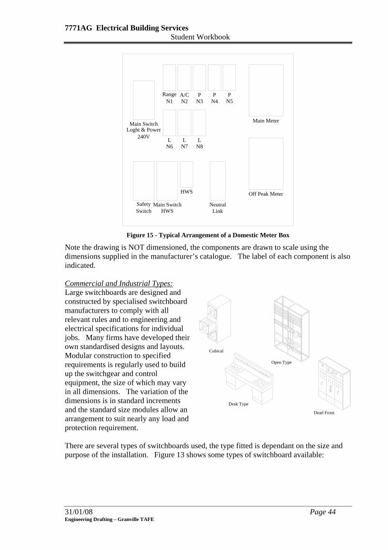
Figure 15 - Typical Arrangement of a Domestic Meter Box
Note the drawing is NOT dimensioned, the components are drawn to scale using the dimensions supplied in the manufacturer’s catalogue. The label of each component is also indicated. Commercial and Industrial Types: Large switchboards are designed and constructed by specialised switchboard manufacturers to comply with all relevant rules and to engineering and electrical specifications for individual jobs. Many firms have developed their own standardised designs and layouts. Modular construction to specified requirements is regularly used to build up the switchgear and control equipment, the size of which may vary in all dimensions. The variation of the dimensions is in standard increments and the standard size modules allow an arrangement to suit nearly any load and protection requirement.
Cubical
Open Type
Desk Type
Dead Front
There are several types of switchboards used, the type fitted is dependant on the size and purpose of the installation. Figure 13 shows some types of switchboard available:
31/01/08 Page 44 Engineering Drafting – Granville TAFE
7771AG Electrical Building Services Student Workbook
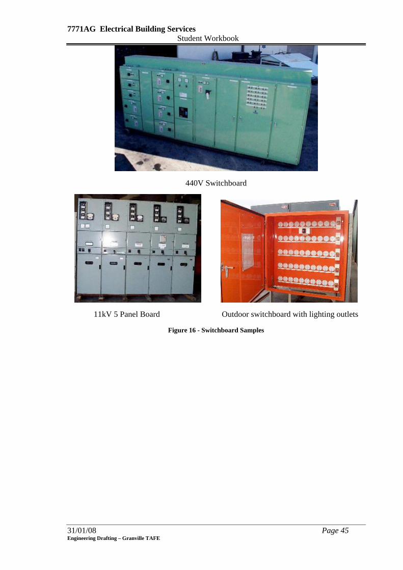
440V Switchboard
11kV 5 Panel Board Outdoor switchboard with lighting outlets
Figure 16 - Switchboard Samples
31/01/08 Page 45 Engineering Drafting – Granville TAFE
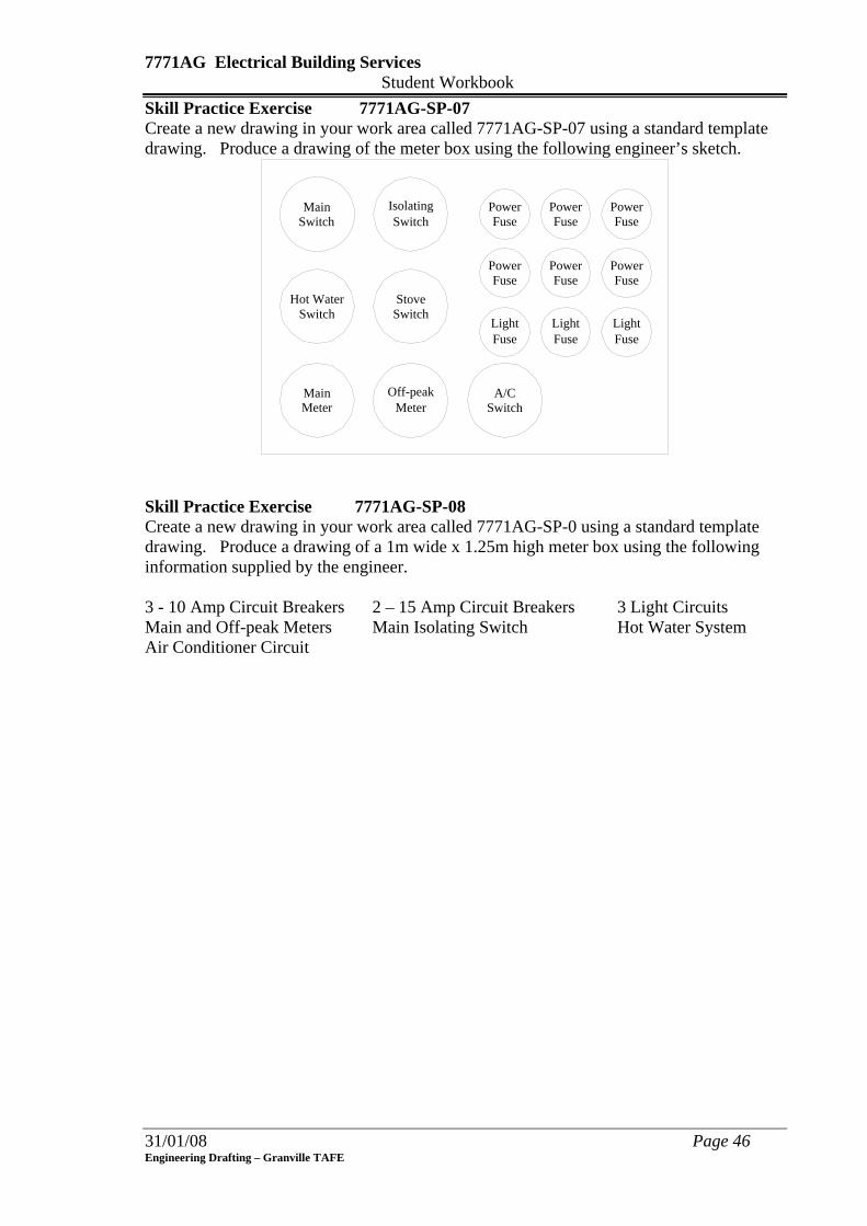
7771AG Electrical Building Services Student Workbook Skill Practice Exercise 7771AG-SP-07 Create a new drawing in your work area called 7771AG-SP-07 using a standard template drawing. Produce a drawing of the meter box using the following engineer’s sketch.
MainSwitch
IsolatingSwitch
SwitchStoveHot Water
Switch
SwitchA/C
MeterMain
FusePower Power
Fuse FusePower
PowerFuse
PowerFuse Fuse
Power
FuseLightLight
FuseLightFuse
MeterOff-peak
Skill Practice Exercise 7771AG-SP-08 Create a new drawing in your work area called 7771AG-SP-0 using a standard template drawing. Produce a drawing of a 1m wide x 1.25m high meter box using the following information supplied by the engineer. 3 - 10 Amp Circuit Breakers 2 – 15 Amp Circuit Breakers 3 Light Circuits Main and Off-peak Meters Main Isolating Switch Hot Water System Air Conditioner Circuit
31/01/08 Page 46 Engineering Drafting – Granville TAFE

7771AG Electrical Building Services Student Workbook
31/01/08 Page 47 Engineering Drafting – Granville TAFE
LESSON 8 - Busway Systems Learning Outcomes: On completion of the session, the participants will be able to:
• Describe a Busway System. • List the advantages of using a Busway System in preference to distribution
boxes and sub-mains. • List the line sizes used to produce Busway System drawings. • Produce a drawing for a Busway System installation.
Overview: The Busway system of power distribution is widely used throughout industry in both commercial and industrial buildings. The busway system is also being increasingly used in low power residential dwelling. The application for busway systems is in power reticulation for high demand industrial areas with concentrated loads and rising mains in multi-storey buildings. The Busway system has been developed for a safe and space-saving transmission and distribution of electrical power. The busway consists of copper or aluminium conductors. These are embedded in a vacuum mixed insulation of epoxy, and filled with selected inert materials of different granulation sizes; the casting mix has high mechanical strength, excellent electrical specifications as well as outstanding physical characteristics. The Busway system is impervious to moisture, as well as being highly fire resistant. An extensive range of element forms can be manufactured for the standardised current ratings in low and medium voltage appliances due to the flexible production method used in universal casting moulds with an integrated processed casting method. Busway systems secure a maintenance-free and safe electrical power supply. The prefabricated elements are self-supporting and the conductors are electrically connected by double fishplate junctions. These junctions contain an oversized contact surface, and minimum of contact resistance to allow for more flexibility during installation. The busduct, busbar and busway systems can be found specified as:
• Total encapsulated busbar
• Fully (epoxy) cast-resin insulated busway
• Epoxy moulded type busduct
• Fire rated electrical busway.
7771AG Electrical Building Services Student Workbook
Sandwich Busbar Isolated Phase Busduct
Small Plug-in Busway Lighting Busway
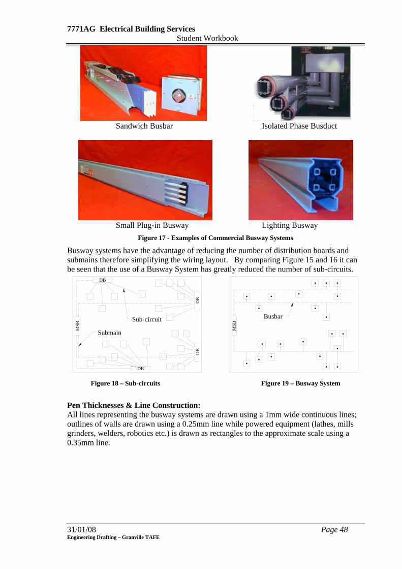
Figure 17 - Examples of Commercial Busway Systems
Busway systems have the advantage of reducing the number of distribution boards and submains therefore simplifying the wiring layout. By comparing Figure 15 and 16 it can be seen that the use of a Busway System has greatly reduced the number of sub-circuits.
DB
DB
MSB
DB
DB
MSB
Busbar
Submain
Sub-circuit
Figure 18 – Sub-circuits Figure 19 – Busway System
Pen Thicknesses & Line Construction: All lines representing the busway systems are drawn using a 1mm wide continuous lines; outlines of walls are drawn using a 0.25mm line while powered equipment (lathes, mills grinders, welders, robotics etc.) is drawn as rectangles to the approximate scale using a 0.35mm line.
31/01/08 Page 48 Engineering Drafting – Granville TAFE
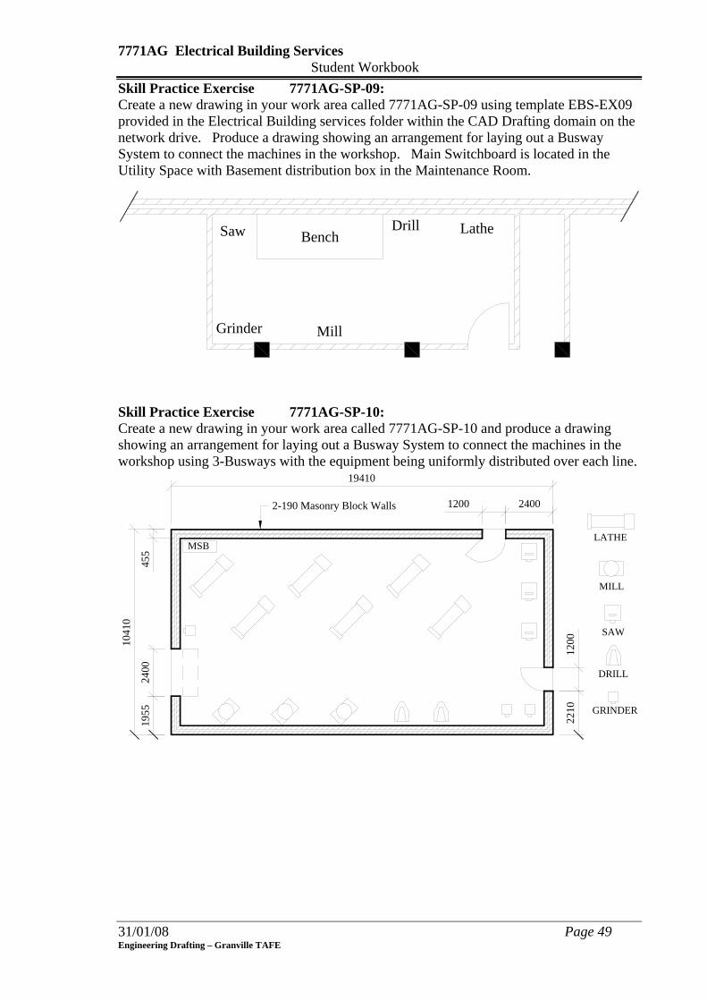
7771AG Electrical Building Services Student Workbook Skill Practice Exercise 7771AG-SP-09: Create a new drawing in your work area called 7771AG-SP-09 using template EBS-EX09 provided in the Electrical Building services folder within the CAD Drafting domain on the network drive. Produce a drawing showing an arrangement for laying out a Busway System to connect the machines in the workshop. Main Switchboard is located in the Utility Space with Basement distribution box in the Maintenance Room.
Bench Lathe
Mill
Drill
Grinder
Saw
Skill Practice Exercise 7771AG-SP-10: Create a new drawing in your work area called 7771AG-SP-10 and produce a drawing showing an arrangement for laying out a Busway System to connect the machines in the workshop using 3-Busways with the equipment being uniformly distributed over each line.
MSB
19410
24001200
1955
2400
1041
0
2210
1200
455
LATHE
MILL
DRILL
GRINDER
SAW
2-190 Masonry Block Walls
31/01/08 Page 49 Engineering Drafting – Granville TAFE

7771AG Electrical Building Services Student Workbook
31/01/08 Page 50 Engineering Drafting – Granville TAFE
LESSON 9 Assessment Test 2: Exercise
Complete all Skill Practice Exercises to 7771AN-SP-09