electrical characteristics of stacks of ybco tapes in...
TRANSCRIPT
IEEE/CSC & ESAS European Superconductivity News Forum (ESNF), No. 15, January 2011
Page 1 of 4
Abstract—Stacks of Second Generation (2G) High
Temperature Superconductor (HTS) tapes were characterized for critical current density and magnetization losses. Effect of external magnetic field on critical current density is studied as a function of number of tapes in the stack and the configuration of stack arrangement. Results of the measurements on stacks of IBAD and RABiTS showed interesting differences. The results suggest that the arrangement of tapes in fabricating high-current cables needs to consider self-field effects, critical current density in external magnetic field, and magnetization losses to optimize the cable configuration for specific applications.
Index Terms—Magnetic field, YBCO, stacked tape, critical
current, magnetization loss, shielding effect.
I. INTRODUCTION S availability of high performance commercial 2G HTS tape is being realized, research activities on
superconducting power devices is expanding. As a result, several HTS power devices are being fabricated and tested as part of utility grid [1], [2].
For high power density HTS power devices, stacked HTS tapes need to be used because single HTS tape has a limited current carrying capacity. The stacked HTS tapes have different electromagnetic characteristics compared with the single HTS tape because of shielding of magnetic field. The characteristics of the screening effects of the stacked tape have been studied by other groups [3]-[6]. For optimal design of the HTS power devices, data is needed on electrical characteristics of stacked HTS tapes and the effect of magnetic field on electrical behavior. Because there are many possible ways of stacking the tapes, a thorough understanding of the properties with respect to stacking arrangement of commercial HTS tapes is essential.
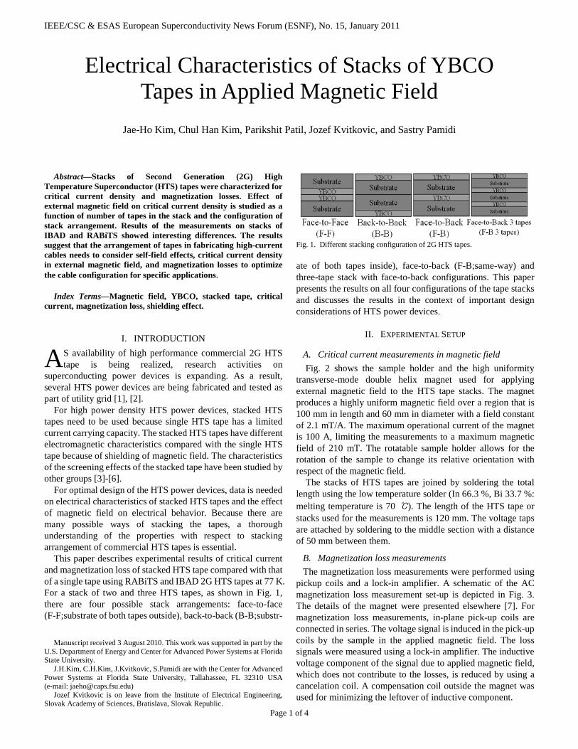
This paper describes experimental results of critical current and magnetization loss of stacked HTS tape compared with that of a single tape using RABiTS and IBAD 2G HTS tapes at 77 K. For a stack of two and three HTS tapes, as shown in Fig. 1, there are four possible stack arrangements: face-to-face (F-F;substrate of both tapes outside), back-to-back (B-B;substr-
Manuscript received 3 August 2010. This work was supported in part by the
U.S. Department of Energy and Center for Advanced Power Systems at Florida State University.
J.H.Kim, C.H.Kim, J.Kvitkovic, S.Pamidi are with the Center for Advanced Power Systems at Florida State University, Tallahassee, FL 32310 USA (e-mail: [email protected])
Jozef Kvitkovic is on leave from the Institute of Electrical Engineering, Slovak Academy of Sciences, Bratislava, Slovak Republic.
Fig. 1. Different stacking configuration of 2G HTS tapes. ate of both tapes inside), face-to-back (F-B;same-way) and three-tape stack with face-to-back configurations. This paper presents the results on all four configurations of the tape stacks and discusses the results in the context of important design considerations of HTS power devices.
II. EXPERIMENTAL SETUP
A. Critical current measurements in magnetic field Fig. 2 shows the sample holder and the high uniformity
transverse-mode double helix magnet used for applying external magnetic field to the HTS tape stacks. The magnet produces a highly uniform magnetic field over a region that is 100 mm in length and 60 mm in diameter with a field constant of 2.1 mT/A. The maximum operational current of the magnet is 100 A, limiting the measurements to a maximum magnetic field of 210 mT. The rotatable sample holder allows for the rotation of the sample to change its relative orientation with respect of the magnetic field.
The stacks of HTS tapes are joined by soldering the total length using the low temperature solder (In 66.3 %, Bi 33.7 %: melting temperature is 70 ℃). The length of the HTS tape or stacks used for the measurements is 120 mm. The voltage taps are attached by soldering to the middle section with a distance of 50 mm between them.
B. Magnetization loss measurements The magnetization loss measurements were performed using
pickup coils and a lock-in amplifier. A schematic of the AC magnetization loss measurement set-up is depicted in Fig. 3. The details of the magnet were presented elsewhere [7]. For magnetization loss measurements, in-plane pick-up coils are connected in series. The voltage signal is induced in the pick-up coils by the sample in the applied magnetic field. The loss signals were measured using a lock-in amplifier. The inductive voltage component of the signal due to applied magnetic field, which does not contribute to the losses, is reduced by using a cancelation coil. A compensation coil outside the magnet was used for minimizing the leftover of inductive component.
Electrical Characteristics of Stacks of YBCO Tapes in Applied Magnetic Field
Jae-Ho Kim, Chul Han Kim, Parikshit Patil, Jozef Kvitkovic, and Sastry Pamidi
A

IEEE/CSC & ESAS European Superconductivity News Forum (ESNF), No. 15, January 2011
Page 2 of 4
Fig. 2. Six layer high uniformity transverse-mode magnet and sample holder.
Fig. 3. Schematic diagram of the AC magnetization loss measurement system.
III. EXPERIMENTAL RESULTS AND DISCUSSION The specifications of the YBCO HTS tapes are shown in
Table I. The critical current of HTS tapes was measured using the high accuracy Signal Conditioning eXtensions for Instrumentation (SCXI) measurement system. The tests were performed on HTS tapes at 77 K, B = 0 and 1 μV/cm criterion.
A. Critical current measurements Figs. 4 (a) and (b) show the normalized critical current (Ic/Ico)
of single HTS tapes (A 1, B 1, C 1) in DC external magnetic field, from 0 to 100 mT applied, perpendicular and parallel to the broader face of the samples, respectively. The normalized critical current of sample A 1, B 1 and C 1 as a function of external magnetic field is shown. The tape samples have similar self-field Ic values (100-110 A). The extent of reduction of Ic in magnetic field, however, is different for each tape.
Samples B 1 and C 1 are both IBAD tapes with identical dimensions. The critical current reduction of sample B 1, however, is smaller than that of sample C 1. Sample B 1 was from a different manufacturing batch with improved in-field performance.
TABLE I SPECIFICATION OF TEST SAMPLES
Sample Num. of tape Conf. Ic [A],
B=0,77K Substrate Dimension (widthⅹthickness)
A
1 Single tape 107.5 Ferromagnetic Ni-W alloy (RABiTS)
4.35mmⅹ0.22mm 2 F-F, F-B, B-B 193 4.35mmⅹ0.51mm
3 Face to Back (3 tape) 298 4.35mmⅹ0.69mm
B
1 Single tape 110 Non- ferromagnetic Hastelloy (IBAD)
4.0mm ⅹ 0.10mm 2 F-F, F-B, B-B 216 4.0mm ⅹ0.21mm
3 Face to Back (3 tape) 323 4.0mmⅹ0.32mm
C
1 Single tape 103 Non- ferromagnetic Hastelloy (IBAD)
4.0mmⅹ0.10mm 2 F-F, F-B, B-B 176 4.0mmⅹ0.21mm
3 Face to Back (3 tape) 242 4.0mmⅹ0.32mm
(a)
(b)
Fig. 4. Normalized critical current of HTS tapes versus DC external magnetic field. (a) Perpendicular magnetic field. (b) Parallel magnetic field.
Fundamentally, the current distribution of short length
stacked HTS tape is dominated by contact resistance between the HTS tapes. The contact resistance can be varied depending on the configuration of stack arrangements (F-F, F-B and B-B). Preliminary tests were performed to confirm that the current distribution between the tapes is uniform by attaching separate voltage taps on each tape. The measurements showed that the current distribution is uniform in each tape of the stacks. Further, the variation of normalized critical current with applied magnetic field of stacks is identical to that of single tapes. Therefore, the test samples used the face-to-face configuration.

IEEE/CSC & ESAS European Superconductivity News Forum (ESNF), No. 15, January 2011
Page 3 of 4
Fig. 5. Normalized critical current of A 1, A 2 (F-F) and A 3 tapes with Ni-W substrate in DC external magnetic field applied.
(a)
(b)
Fig. 6. Comparison of the normalized critical current of B 1, B 2 (F-F) and B 3 tapes in DC external magnetic field applied. (a) Perpendicular magnetic field. (b) Parallel magnetic field.
The comparisons of normalized critical current of A 1, A 2 (F-F) and A 3 made using Ni-W substrate, in applied perpendicular and parallel magnetic fields are shown in Fig. 5. The fractional values of critical current of sample A at 100 mT
(a)
(b)
Fig. 7. Comparison of the normalized critical current of C 1, C 2 (F-F) and C 3 tapes in DC external magnetic field applied. (a) Perpendicular magnetic field. (b) Parallel magnetic field. parallel field for A 1, A 2 (F-F) and A 3, respectively, are 87.5 %, 88.5 % and 89.5 %. At 100 mT perpendicular magnetic field, the fractional values of critical current of sample for A 1, A 2 and A 3, respectively, are 75.7 %, 76.8 % and 77.4 %. The normalized critical current values of sample A do not change as significantly for sample B probably because of the ferromagnetic substrate effect.
Fig. 6 and Fig. 7 show the normalized critical current of B 1, B 2 (F-F), B 3 and C 1, C 2 (F-F), C 3 samples in applied perpendicular and parallel magnetic fields. The samples B and C have non-ferromagnetic, hastelloy substrate. The extent of reduction of critical current of sample B and C is different. For sample B, the fractional critical current values at 100 mT perpendicular field of B 1, B 2 (F-F), and B 3 are 58 %, 67 %, and 75 %, respectively. For sample C, 100 mT perpendicular magnetic field, the fractional critical current values for single, C 1, C 2 (F-F) and C 3 are 33 %, 40 %, and 46 %, respectively. However, the normalized critical current reduction becomes smaller as increasing the number of tapes in the stack. Magnetic shielding by one another increases with the number of tapes and due to this the local magnetic filed on the tapes is lower in the stacks compared to that of a single tape [8].
IEEE/CSC & ESAS European Superconductivity News Forum (ESNF), No. 15, January 2011
Page 4 of 4
(a)
(b)
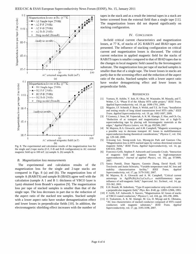
Fig. 8. The experimental and calculation results of the magnetization loss for the single and 2-tape stacks (F-F, F-B and B-B configuration) in AC external magnetic field up to 100 mT. (a) sample A. (b) sample B.
B. Magnetization loss measurements The experimental and calculation results of the
magnetization loss for the single and 2-tape stacks are compared in Figs. 8 (a) and (b). The magnetization loss of sample A (RABiTS) and sample B (IBAD) agree well with the calculation (sample A 1 and B 1: thickness of YBCO layer is 1μm) obtained from Brandt’s equation [9]. The magnetization loss per tape of stacked samples is smaller than that of the single tape. The loss decreases in part due to the reduction of the aspect ratio of the stacked test samples. Stacked sample with a lower aspect ratio have weaker demagnetization effect and lower losses in perpendicular fields [10]. In addition, the electromagnetic shielding effect increases with the number of
tapes in the stack and as a result the internal tapes in a stack are better screened from the external field than a single tape [11]. The magnetization losses did not depend significantly on stacking configuration.
IV. CONCLUSION In-field critical current characteristics and magnetization
losses, at 77 K, of stacks of 2G RABiTS and IBAD tapes are presented. The influence of stacking configuration on critical current and magnetization losses is discussed. The critical current reduction in applied magnetic field for the stacks of RABiTS tapes is smaller compared to that of IBAD tapes due to the changes in local magnetic field caused by the ferromagnetic substrate. The magnetization loss per tape of stacked samples is smaller than that of a single tape. The lower losses in stacks are partly due to the screening effect and the reduction of the aspect ratio of the stacks. Stacked samples with a lower aspect ratio have weaker demagnetizing effect and lower losses in perpendicular fields.
REFERENCES [1] Yumura, H. Ashibe, Y. Itoh, H. Ohya, M. Watanabe, M. Masuda, and T.
Weber, C.S, “Phase II of the Albany HTS cable project,” IEEE Trans. Applied Superconductivity, vol. 19, pp. 1698-1701, 2009.
[2] Maguire, J.F. Schmidt, F. Bratt, S. Welsh, and T.E. Jie Yuan, “Installation and testing results of long island transmission level HTS cable,” IEEE Trans. Applied Superconductivity, vol. 19, pp. 1692-1697, 2009.
[3] F.Gomory, J. Souc, M. Vojenciak, A. K. M. Alamgir, Z. Han, and Ch. Gu, “Reduction of ac transport and magnetization loss of a high-Tc superconducting tape by placing soft ferromagnetic materials at the edges,” Applied Physics Letters, vol. 90, pp. 092506, 2007.
[4] M. Majoros, B.A. Glowacki, and A.M. Campbell, “Magnetic screening as a possible way to decrease transport AC losses in multifilamentary superconductors-basing theoretical considerations,” Physica C, vol. 334, pp. 129-140, 2000.
[5] Ji-kwang Lee, Seung-wook Lee, Myung-jin Park and Gueesoo Cha, “Magnetization loss in HTS stacked tapes by various directional external magnetic fields,” IEEE Trans. Applied Superconductivity, vol. 14, pp. 630-633, 2004.
[6] Francesco Grilli, Stephen P. Ashworth and Leonardo Civale, “Interaction of magnetic field and magnetic history in high-temperature superconductors,” Journal of applied Physics, vol. 102, pp. 073909, 2007.
[7] Sastry Pamidi, Doan Nguyen, Guomin Zhang, David Knoll, Ulf Trociewitz and Justin Schwartz, “Variable temperature total AC loss and stability characterization facility,” IEEE Trans. Applied Superconductivity, vol. 17, pp. 3179-3182, 2007.
[8] M. Majoros, B. A. Glowacki and A. M. Campbell, “Critical current anisotropy in Ag/(Pb,Bi)2Sr2Ca2Cu3O10+x multifilamentary tapes: influence of self-magnetic field,” Supercond. Sci. Technol., vol. 14, pp. 353-362, 2001.
[9] E.H. Brandt, M. Indenbom, “Type-II superconductor strip with current in a perpendicular magnetic field,” Phys. Rev. B 48, pp. 12893-12906, 1993.
[10] F. Grilli, S.P. Ashworth, S. Stavrev, “Magnetization AC losses of stacks of YBCO coated conductors,” Physica C, vol. 434, pp. 185-190, 2006.
[11] O. Tsukamoto, A. K. M. Alamgir, M. Liu, D. Miyagi and K. Ohmatsu, “AC loss characteristics of stacked conductor composed of HTS coated conductors with magnetic substrates,” IEEE Trans. Applied Superconductivity, vol. 17, pp. 3195-3198, 2007.