electrical engineering by prof. j r lucas
DESCRIPTION
Basics of Electrical EngineeringTRANSCRIPT

EE 101 Electrical Engineering Overview
University of Moratuwa - JRL/September 2008 1
EE 101 Electrical Engineering (2 Credits) taught by Rohan Lucas, Janaki Premaratne, Nalin Wickramarachchi, Anula Wijayapala
Syllabus Overview (4 hrs) Electrical Power and National Development, Role of Electrical Engineer, Introduction to Power Generation, Transmission, Distribution and Utilisation including Modern Drives, SI Units, Basic concepts. Network Theorems (4 hrs) Ohm’s Law, Kirchoff’s Law, Superposition Theorem, Thevenin’s theorem, Norton’s theorem, maximum power transfer theorem, Millmann’s theorem; star-delta transformations. Introduction to nodal and mesh analysis.. Alternating Current theory (6 hrs) Sinusoidal waveform, phasor and complex representation, Impedance, Power and Power factor. Analysis of simple R, L, and C circuits using alternating current Solution of simple network problems by phasor and complex number representation. Three Phase - Advantage of three phase, Star and Delta configurations. Phase sequence. Balanced and unbalanced systems. Power factor correction. Electromagnetic and Electrostatic theory (2 hrs) Basic electrostatic and electromagnetic theory; force and torque development in magnetic circuits. Electrical Measurements (3 hrs) Direct deflection and null deflection methods. Ammeters, voltmeters, wattmeters, energy meters. Extension of ranges. Electrical Installations (3 hrs) Fuses, miniature circuit breakers, earth leakage circuit breakers, residual current circuit breakers, earthing, electric shock. IEE wiring regulations, basic domestic installations.
1.0 Overview You may find it amusing that this lecture series starts with a cartoon which appeared in the magazine Punch in London on 25th June 1881(Figure 1.1). It shows King Steam and King Coal discussing Baby Electricity’s chances of success in life. Baby electricity is obtaining nourishment from the feeding bottle marked “storage of force”. Prior to 1881, Coal gas was widely used to obtain light and steam was used to drive machinery and as such the advent of baby electricity into this market made King Coal and King Steam become anxious about their future. It was around this time that electricity started gaining ground for lighting and for power applications. The success was based primarily on the discovery of electromagnetic induction and the construction of the first dynamo by Michael Faraday in 1831. From ancient times, the use of non human forms of energy transfer has been associated with the development of man. For example, stone age man used spears to hunt animals for food. However he had to be close enough to be able to succeed. But this had a lot of dangers. So he
invented the bow and arrow.
The bow is slowly bent by the hunter in more than a few seconds and energy is stored in the springy wood. However it is released in a fraction of a second on to the arrow so that it moves at many times the velocity that the man could have thrown at, and so can operate it in from a much further distance. [Note that the original muscle energy in man was converted to potential energy in the bow and kinetic energy in the arrow. The man in turn gets his energy from the food - principle of conservation of energy]. Animal power was also used by man to materially improve himself.
Figure 1.1 “What will he Grow to ?”

EE 101 Electrical Engineering Overview
University of Moratuwa - JRL/September 2008 2
Water power in water wheels and wind power through wind mills were the first forms of non-muscle power to be used. The invention of the steam engine in the 1780s was a real break through in that it lead to an ever increasing material progress. With the advent of large scale electrical generation and transmission about 100 years later, the rate of increase of power has been rocketing. Although this is wonderful for our material prosperity, the machines too have to be fed and our limited resources of fossil fuel, as is used today, are fast dwindling. The standard of living of a country can be measured by the amount of energy consumed per person (per capita consumption). While many developed countries need energy to heat the environment during the harsh winter we are fortunate not to have that requirement. Even so our per capita consumption of energy is still too low for us to become an industrialised country. Engineering economics play a vital role in the development of a country. The role of the electrical engineer is to facilitate the means by which this can be achieved through the proper management of resources. His role is to economically design, operate, maintain and manage the equipment associated with the generation, transmission, distribution and utilisation of electrical energy and at the same time maintaining safety. He should also be able to adequately communicate with the lower and higher rungs of the organisation, and be able to relate to the environment. He must realise that electrical engineering is an ever expanding field and that he needs to continually develop himself to meet the needs of society and that industrial problems rarely have a well defined or unique solution.
Generation, transmission and distribution are directly concerned with electrical power and are handled by supply authorities. Utilisation is by all walks of people for all types of purposes. The electrical equipment would consist not only of purely electrical equipment such as for lighting, heating, machinery, and transport but also for other applications such as computers and communication equipment. In the past over 90% of motors used in industry have been traditional induction motors. In the present day, more and more power electronic devices are used to control motors. 1.1 Generation, Transmission and Distribution of Electricity The consumer needs to use electricity for his day to day activities in his home, office or other workplace. It is neither economical nor feasible to produce electricity (i.e. convert from non electrical form of energy to electrical energy) where it is required. Thus electricity is produced centrally in generating stations. In the home or office, we would normally use electricity at 230 V (110 V is used in the US) between live and neutral wires – phase voltage. Voltages higher than that would not be at all safe and voltages lower than that would not be economical as they require larger currents and hence larger size conductors [Note: for the same power output, a lower voltage would require a higher current]. We would also have a protective earth wire to give us additional safety. The supply is an alternating current at a frequency of 50 Hz. A typical house in Sri Lanka would normally not consume more than about 2 to 3 kW of power even during the peak giving a peak current of about 10 A. Since there are a number of houses down your lane and all of them require electricity a common distribution line is run along the side of the road and power is tapped for each house from it using 2 wires (live and neutral) and the earth wire is provided from an electrode at your premises. When the current flows, there will be a considerable power loss in both the live and neutral wires and a considerable voltage drop [Note: voltage drop is different from the voltage of the line] You are familiar with the fact that forces along three sides of an equilateral triangle add up to zero. Likewise, three currents, equal in magnitude but with phase angles of the sinusoidal waveform differing by 1200 (or 2π/3 rad), would add up to zero.
Figure1.2 - Three phase waveforms-100
-50
0
50
100
0.000 1.571 3.142 4.712 6.283
angle (rad) curr
ent
R phase Y phase B phase
Making use of this property, if we could balance the electrical loads taken by the various households equally into three phases and supply them at different phase angles (as shown in figure 1.2), we would have almost no
WWW.UCETWEB.WORDPRESS.COM
Brought To You By: PRINCE MUFA

EE 101 Electrical Engineering Overview
University of Moratuwa - JRL/September 2008 3
neutral current. Thus the total power loss would be effectively halved. Therefore power distribution is normally carried out using three phase.
Using trigonometry, it can be easily shown (figure 1.3) that the voltage between two live wires would now not be 230 V but 2 × 230 × √3/2 or 400 V. [The voltage between live and neutral is still 230 V]. Thus the low voltage distribution from which supply is obtained to your house is called 400 V, 3 phase, 50 Hz supply. The house in turn has a 230 V, 1 phase, 50 Hz supply.
When we consider all the houses down your lane, and perhaps the adjacent lane, the total current may approach around 500 A per phase and would require a power supply of the order of 350 kVA.
Since the power loss in a line is proportional to the square of current (I2R), the loss rapidly increases with increase in current or power distributed (VI). This power loss may be reduced by sending the power at a higher voltage as power loss is proportional to the square of current, while power distributed is proportional to the current.
Thus power is distributed at a higher voltage such as 3 phase, 11 kV (Lanka Electricity Company) or 3 phase, 33 kV (Ceylon Electricity Board). Big industries (such as Steel Corporation) and large workplaces (such as University of Moratuwa) are supplied at these voltages. The voltage is stepped down from these voltages to 3 phase, 400 V using transformers (usually rated at 100 kVA, 250 kVA, 400 kVA etc) for low voltage distribution. Thus there are two levels of distribution - low voltage and medium voltage (figure 1.4).
Generating stations (ex. Kotmale, Victoria, Laxapana) are commonly located hundreds of kilometers away from the Load Centre (ex: Colombo). Also there would be thousands of transformers supplying the low voltage distribution systems. Thus it is not economical to transmit over long distance at 11 kV or even 33 kV. Also, in such transmission, it is point to point (such as from Kotmale to Kolonnawa) and in bulk. Thus high voltage transmission is carried out in Sri Lanka at 132 kV and more recently at 220 kV to keep the power losses low. The power transfer would be of the order of 100 MW. [For a given conductor size and power transfer, an increase of voltage by a factor of 20 times would reduce the current by a factor of 20 times and the power loss by a factor of 400 times].
In some countries, where the power transfer requirements are much higher and the distances much longer, extra high voltage transmission at voltages higher than about 345 kV (ex: 400 kV, 760 kV etc) are used. Unfortunately, it is not feasible at present to generate electricity at more than about 25 kV (A Powerformer is being developed in Sweden capable of generating at high voltages required for transmission) so that the normal generation is done using Synchronous Generators at about 11 to 15 kV (typically 13.8 kV). This is stepped up to the transmission voltage using transformers. The transmission voltage in Sri Lanka is 132 kV and 220 kV.
Figure 1.3
Generating Station13.8 kV
Transmission Line220 kV
Transmission Line132 kV
Distribution Lines33 kV
Load33 kV, 3 φ
Loads230V, 1 φ
Loads230 V,1 φ
Distribution Line, 400 V
Distribution Line, 400 V
Distribution Lines11 kV
Loads400 V,3 φ
Loads400 V, 3φ
Figure 1.4 - Typical arrangement of part of a power system
230 V
400 V 300 1200
Red
Yellow Blue
WWW.UCETWEB.WORDPRESS.COM
Brought To You By: PRINCE MUFA

EE 101 Electrical Engineering Overview
University of Moratuwa - JRL/September 2008 4
1.2 Bulk Energy Sources Energy sources for bulk power generation can be categorised into renewable energy sources (ex: hydro-electric, solar, wind etc) and non-renewable energy sources (coal, oil etc). Some of the more common ones are outlined in the following section. (i) Hydro-electric power Perhaps the oldest form of large scale energy conversion has been by the use of water power which were used in ancient water wheels. In the modern hydro-electric power stations, the energy of water (either in potential form or kinetic form) is first converted to rotational (mechanical) energy in the turbine and then to electric energy in the generator. Although the water which gives the energy is free, a high capital civil engineering cost is associated with the construction and the overall cost per kWh may approach that of conventional thermal plants. Micro-hydro and mini-hydro plants are also used and connect to the distribution network directly rather than to the transmission network.
(ii) Conventional thermal power (Coal & Oil) The burning of coal or oil in boilers produces steam at high temperature and pressure (conversion of chemical energy to thermal energy and then to kinetic energy). This steam is used to rotate a steam turbine (thermal energy to mechanical energy conversion) which is coupled to an electric generator (mechanical energy to electrical energy). Even though continual advances have been made the efficiency of thermal stations is quite low (around 40%) because of the vast quantities of heat lost to the surroundings. (iii) Gas turbines Gas turbine plants also operate by burning oil. However the energy transfer is not through steam but through compressed gasses produced in the combustion chamber under high pressure which drives the gas turbine. The gas turbine is mechanically coupled to the electrical generator to produce electricity. (iv) Nuclear Power Plants The energy source in a nuclear power plant is the energy stored in the nuclei of the atoms of the fuel. Energy is released by the splitting of a nucleus in a process called fission. Energy released by the combination of two light nuclei to form a single heavier nucleus is called fusion. So far power has only been successfully obtained from the fission reaction. Uranium is the commonly used fuel and U235 is fissile. When struck by slow moving neutrons its nucleus splits into two substantial fragments with high kinetic energy (about a million times larger than in a chemical reaction). The fast moving fragments hit surrounding atoms producing heat. The neutrons released in the fission reaction cause further fissions and under correct conditions lead to a chain reaction. The chain reaction is controlled by the use of reaction absorbers placed in control rods. The heat generated is used to produce steam which in turn drives a steam turbine coupled to an electrical generator as in a coal or oil power plant. (v) Wind Power Plants Wind is continuously regenerated in the atmosphere under the influence of the energy radiated from the sun. (about 20% of the solar energy of the atmosphere is converted to wind energy). The kinetic energy in the wind is used to turn a wind turbine. The energy produced in a wind turbine is proportional to the cube of the wind velocity. Wind turbines (usually 2 or 3 bladed) must be mounted on tall towers for greater efficiency as wind velocity is higher at higher altitudes. To obtain large scale electric power, a large number of wind turbines are arranged in a wind farm. One of the disadvantages of wind power is that it is not continuously available. We have about 150-200 MW of wind potential in the coastal belt in Sri Lanka. (vi) Solar Energy Energy generated by the sun is due to a nuclear reaction called fusion. The energy that is received on the earth from the sun is over 10,000 times the present energy requirements of the earth. The average solar radiation received by the earth is about 0.2 kW/m2. In large scale installations, the sun’s rays may be concentrated by lenses or mirrors. These lenses or mirrors need to have steering mechanisms to follow the motion of the sun and to focus the heat on solar towers. The heat can be used to produce steam to drive steam turbines. Photo-voltaic power using solar cells is also used to produce electricity. In these the solar radiation is directly converted into electricity. At present solar cells are expensive and are not used for large scale generation of power but may be used in some rural electrification schemes. However these require power storage as electricity is not produced at night when it is most needed for lighting.
WWW.UCETWEB.WORDPRESS.COM
Brought To You By: PRINCE MUFA

EE 101 Electrical Engineering Overview
University of Moratuwa - JRL/September 2008 5
A very important use of Solar energy is in powering remote power applications such as repeater stations, transmitters at hill tops, and in extra terrestrial applications. (vii) Geothermal Energy Geothermal energy is the heat from the inside of the earth. The temperature of the earth crust increases from about 200C at the earth’s surface to about 10000C at a depth of 40 km. Energy can be obtained by drilling at suitable locations to release high pressure steam or hot water which is produced by ground water coming into contact with molten rock. These can be circulated through a heat exchanger to produce steam to run a steam turbine. In areas where the ground water supply is limited, water could be pumped into a cavity created in the hot rock to obtain hot water and steam. (viii) Ocean Energy Energy from the ocean can be developed in three different ways. These are (a) tidal power, (b) ocean waves and (c) ocean thermal gradient. In tidal power, we make use of the tide which occurs twice a day and rises and falls by as much as 10m. When the tide rises, water flows in to the land and when the tide falls, water flows out. This vast amount of energy transfer can be used to generate electrical energy using hydro turbines. Ocean waves are created by the wind and a vast amount of energy is available in the waves. A kilometer long, one meter wave would contain about 10 MW of power. Reciprocating generators are commonly used. The mechanism to trap the wave energy would be moored in the middle of the ocean (say 80 km from shore). Ocean thermal energy conversion (OTEC) uses the natural temperature difference between the warm surface water (250C) and the cooler ocean bed at 50C. Due to the low temperature difference, the turbines use fluids such as ammonia as the working fluid. About 50 km away from the coast line in Sri Lanka, in Mannar, Trincomalee and Unawatuna, are some of the best sites for OTEC in the world. A 1 MW OTEC plant is under construction near Mannar. (ix) Magneto hydro-dynamic (MHD) Generation Magneto hydro dynamic generation is also based on Faraday’s laws of induction. The main difference from a conventional generator is that the conductor is a gas at a very high temperature and pressure where it is conductive. The gas may also be seeded with a small amount of vaporised metal such as potassium. In MHD generation, the gas passes through a pipe (whose cross-section gradually increases from beginning to end) across which a magnetic field is applied (in a perpendicular direction to the flow of gas). An emf is thus induced in a circuit in a third mutually perpendicular direction. (x) Fuel Cells Fuel cells use hydrogen-oxygen interaction through a catalyser to yield a flow of electrons in a load connected externally. Each cell develops about 0.7V and sufficient modules in series yield an output voltage of around 11-15 kV and can reach power outputs of around 1 MW. (xi) Biomass energy Biomass is the abbreviation for biological mass, the amount of living material provided by a given area of the earth's surface. Biomass energy may be obtained from forests, vegetation and animal refuse. In various forms, it is probably the major supplier of energy in Sri Lanka.
1.3 Utilisation (i) Electric Drives Due to the various advantages of electric drives, they are universally used in industry. They may operate on either alternating current (a.c.) or direct current (d.c.). Most applications use a.c. induction motors. However they operate at almost constant speed and low starting torque. For variable speed drives and high starting torque applications d.c. has been preferred. However, with modern power electronic controlled drives a.c. motors may also be controlled relatively easily. (ii) Electrical Heating The heating characteristic of an electric current is used extensively in industrial and domestic heating applications. They have relatively high efficiency (>75%), clean, easy to control, low maintenance and can be protected against overheating easily. Electric heating can be obtained from (a) resistance heating, (b) induction heating, (c) eddy current heating (d) dielectric heating, and (e) electric arc heating. (iii) Electric Welding The word welding means the joining of two metals together by heating them to melting point. In electrical welding, a very high electric current produces the heat needed to melt the material. Due to the reliability of the
WWW.UCETWEB.WORDPRESS.COM
Brought To You By: PRINCE MUFA

EE 101 Electrical Engineering Overview
University of Moratuwa - JRL/September 2008 6
welded joints in comparison to riveted or bolted joints, electrical welding has been adopted in many fields of engineering. The types of electric welding are resistance welding and arc welding. (iv) Air Conditioning By air conditioning, the temperature, humidity and the purity of the air are controlled. In tropical countries like Sri Lanka, air conditioning only cools the air and not heats it, but in cold countries both modes are available. The working substance in the cooling type of air conditioner is the refrigerant vapour which readily evaporates and condenses. (v) Electric Lighting Light is electromagnetic radiation of a wavelength to which the eyes are sensitive (380 nm to 780 nm), bounded at one end by infra-red radiation of 780 to 10,000 nm and ultra-violet radiation of 10 nm to 380 nm wave length at the other end. The colour associated with the various wavelengths are given in table 1.
Wave length (nm) 380-420 420-495 495-566 566-589 589-627 627-780
colour violet blue green yellow orange red table 1
The eye is most sensitive to the colour yellow-green (wavelength = 555 nm). Light sources are based on one of the following principles. (a) Incandescent type - Incandescent filament type lamps emit light when heated to high temperature. Typical
incandescent lamps emit about 10 to 15 lm/W. (b) Fluorescent type - Fluorescent lamps operate by transforming ultra violet rays into radiation of longer
wavelength lying in the visible spectrum. Typical fluorescent lamps emit about 50-70 lm/W. (c) Gas discharge type - Operate on the principle of visible radiation when an electric discharge occurs in a gas
or metal vapour. Sodium vapour lamp is a typical example of a gas discharge lamp and have efficacies of about 100 lm/W.
(vi) Electric Traction Two major application of electric traction are electric trains and electric hoists. The good controllability of speed and torque of electrical drives without resorting to lossy gear systems is used in these applications. In addition to this characteristic, the very high initial torque and almost constant power requirement in a vast range of speed torque combinations of a DC series motor is frequently utilised. This allows the Internal Combustion (IC) engine in a train, supplying power to the generator, to run at relatively low range of speeds, even at high running speeds of the train. This enhances efficiency and cuts down wear and tear of the engine significantly. (vii) Electrochemistry and Electrometallurgy Electrical energy is extensively used in metallurgical and chemical industries for the extraction, refining and deposition of metals and manufacture of chemicals. Though the various processes are different in apparent detail, they are fundamentally alike, being based on the principle of electrolysis. Extraction and refining of metals are similar electrochemical processes except that extraction is the term used for the production of metals with commercially acceptable purity, while refining is the process by which a highly concentrated of metals is subjected to electro-chemical treatment for recovering not only the principal metal in pure form, but also the precious metals like silver gold etc which may be present in the form of minute traces. (viii) Electronics Electronics is the branch of science that deals with flow of electrons and other charged particles through gases, vacuum and semiconductor materials. The principle electronic devices are the vacuum tubes, gas-filled tubes, and semiconductor devices like selenium rectifiers, silicon diodes, transistors and silicon controlled rectifiers. The applications of electronic devices and their circuit arrangements are numerous and varied (ix) Information storage and transmission The computer is the most powerful tool designed by man. Today’s computer is a complex electronic machine capable of storing, processing, manipulating and retrieving large volumes of data/information at incredibly high speeds. Consequently they are finding ever increasing applications in every field of industrial, commercial and business activity, science and space research, medical diagnostics etc resulting in greater production, higher productivity, reduced costs and more reliable and accurate results. (x) Biomedical Systems Bioelectrical Engineering is the area of biomedical engineering concerning bioelectric activity, which encompasses the nervous system and regulates most life processes. The bioelectrical engineer assists this
WWW.UCETWEB.WORDPRESS.COM
Brought To You By: PRINCE MUFA

EE 101 Electrical Engineering Overview
University of Moratuwa - JRL/September 2008 7
regulation and uses bioelectric signals for diagnostic purposes. Developments have led to the invention of the pacemaker, the defibrillator, and the electrocardiograph. The monitoring of many other bioelectric functions by means of electrodes plays an important part in surgical recovery rooms and intensive-care units.
WWW.UCETWEB.WORDPRESS.COM
Brought To You By: PRINCE MUFA

EE 101 Electrical Engineering 2001/02 Electric Motors
University of Moratuwa - JRL/September 2008 8
1.4 Electric Drives 1.4.1 Electromechanical energy conversion:
Electrical Energy is obtained by the conversion of other forms of energy, based on the principle of conservation of energy. The main advantage of this conversion is that energy in electrical form can be transmitted, utilised and controlled more easily, reliably and efficiently than in any other form.
An electro-mechanical energy conversion device is one which converts electrical energy into mechanical energy (electric motors) or mechanical energy into electrical energy (electric generators). The electro-mechanical energy conversion process is a reversible process. However, devices are designed and constructed to suit one particular process rather than the other. In an energy conversion device, out of the total input energy, some energy is converted into the required form, some energy is stored and rest is dissipated.
For practical application we need to convert electrical energy into the required useful form, such as mechanical energy, heat, light, sound and electromagnetic waves. One of the major applications is electric drives which uses motors.
Figure 1.5 - Power flow in an electric motor The energy balance for a motor (shown in block diagrammatic form in figure 1.5) can be written as
Total electrical energy input = mechanical energy output + total energy stored + total energy dissipated
In a motor, energy is stored in the magnetic field and mechanical system. The energy dissipated is in the electric circuit as ohmic losses, in the magnetic circuit as core losses (hysteresis and eddy-current losses), and in the mechanical system as friction and windage losses. [ω is the angular velocity of rotation]. An electric motor provides the driving torque necessary to keep machinery running at the required speed, with provision being made for speed control and reversal of rotation. The electrical motor is required to start, accelerate, drive and decelerate its load, within certain limitations. There are three main types of motors - Direct Current Motor, Induction Motor and Synchronous Motor
Direct Current (dc) Motors
Direct current (dc) motors operate on a magnetic field produced by the field winding in the stator (stationary part of the motor) interacting with the field produced by the armature winding in the rotor (rotating part). The basic constructional features of a typical two-pole dc motor are shown in figure 1.6 and the circuit model in figure 1.7.
Figure 1.6 - two-pole dc motor Figure 1.7 - Circuit model of a dc motor
The dc motor needs slip rings or split rings (commutator) on the rotor shaft and a set of brushes positioned over them to supply the armature winding. [symbol for the armature basically shows the rotor and a pair of brushes]
(a) separately excited (b) shunt excited (c) series excited (d) compound excited
Figure 1.8 - categorisation of dc motors
shaft
Electric Motor Pstored, elect Pstored, mech
Mechanical
Load
Ploss,elect
Pinput
Ploss,mech
Poutput
ω
dc supply dc supply dc supply dc supply dc supply
−
Vf field supplyarmature supply
+
−V
+Rf
ra Ea If
+
−ω τ
Pmech V = Ea + ra Ia
Ia
WWW.UCETWEB.WORDPRESS.COM
Brought To You By: PRINCE MUFA
EE 101 Electrical Engineering 2001/02 Electric Motors
University of Moratuwa - JRL/September 2008 9
The dc motors can be categorised into four basic types dependent on the method of connection of the field winding (figure 1.8). These are the (a) separately excited field, (b) shunt connected field, (c) series connected field, and (d) compound connected field.
In the separately excited type, the field winding is connected to a separate or external dc source. In the shunt excited type, the field winding is connected in parallel with the armature winding so that the same dc voltage source is used. In the series excited type, the field winding is connected in series with the armature winding, again making use of the same dc voltage source. Compound excitation involves both the series and shunt excited windings.
In the case of very small motors, the field may be created by a permanent magnet rather than having a field winding. These are known as permanent magnet dc motors.
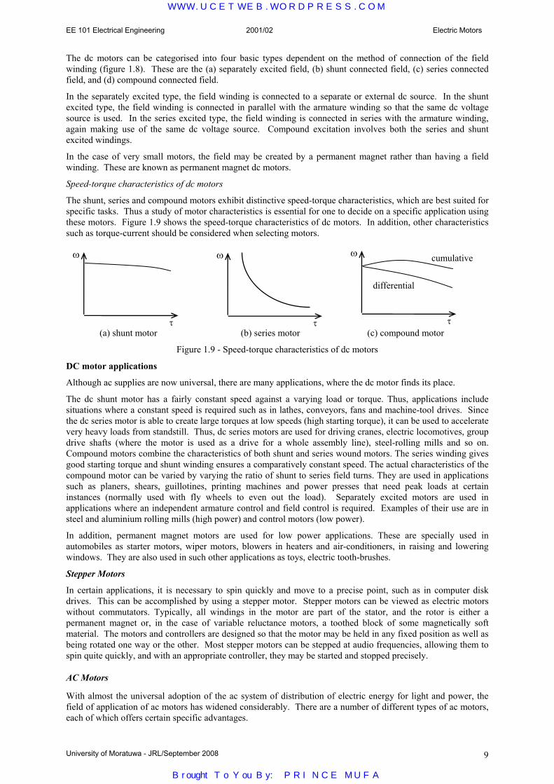
Speed-torque characteristics of dc motors
The shunt, series and compound motors exhibit distinctive speed-torque characteristics, which are best suited for specific tasks. Thus a study of motor characteristics is essential for one to decide on a specific application using these motors. Figure 1.9 shows the speed-torque characteristics of dc motors. In addition, other characteristics such as torque-current should be considered when selecting motors.
(a) shunt motor (b) series motor (c) compound motor
Figure 1.9 - Speed-torque characteristics of dc motors
DC motor applications
Although ac supplies are now universal, there are many applications, where the dc motor finds its place.
The dc shunt motor has a fairly constant speed against a varying load or torque. Thus, applications include situations where a constant speed is required such as in lathes, conveyors, fans and machine-tool drives. Since the dc series motor is able to create large torques at low speeds (high starting torque), it can be used to accelerate very heavy loads from standstill. Thus, dc series motors are used for driving cranes, electric locomotives, group drive shafts (where the motor is used as a drive for a whole assembly line), steel-rolling mills and so on. Compound motors combine the characteristics of both shunt and series wound motors. The series winding gives good starting torque and shunt winding ensures a comparatively constant speed. The actual characteristics of the compound motor can be varied by varying the ratio of shunt to series field turns. They are used in applications such as planers, shears, guillotines, printing machines and power presses that need peak loads at certain instances (normally used with fly wheels to even out the load). Separately excited motors are used in applications where an independent armature control and field control is required. Examples of their use are in steel and aluminium rolling mills (high power) and control motors (low power).
In addition, permanent magnet motors are used for low power applications. These are specially used in automobiles as starter motors, wiper motors, blowers in heaters and air-conditioners, in raising and lowering windows. They are also used in such other applications as toys, electric tooth-brushes.
Stepper Motors
In certain applications, it is necessary to spin quickly and move to a precise point, such as in computer disk drives. This can be accomplished by using a stepper motor. Stepper motors can be viewed as electric motors without commutators. Typically, all windings in the motor are part of the stator, and the rotor is either a permanent magnet or, in the case of variable reluctance motors, a toothed block of some magnetically soft material. The motors and controllers are designed so that the motor may be held in any fixed position as well as being rotated one way or the other. Most stepper motors can be stepped at audio frequencies, allowing them to spin quite quickly, and with an appropriate controller, they may be started and stopped precisely.
AC Motors
With almost the universal adoption of the ac system of distribution of electric energy for light and power, the field of application of ac motors has widened considerably. There are a number of different types of ac motors, each of which offers certain specific advantages.
ω
τ
ω
τ
ω
τ
differential
cumulative
WWW.UCETWEB.WORDPRESS.COM
Brought To You By: PRINCE MUFA

EE 101 Electrical Engineering 2001/02 Electric Motors
University of Moratuwa - JRL/September 2008 10
The supply for these motors is either 3-phase or single-phase. 3 phase motors are found in larger sizes and have mainly industrial applications. Single-phase motors are used mainly for domestic and agricultural applications. In the fractional kilowatt sizes, they are used in large numbers for washing machines, refrigerators and so on. AC motors are classified to various groups based on their principle of operation; most common are the induction motor and synchronous motor. Induction Motors As the name implies, the induction motor is based on the induced voltage in a winding in the rotor. The rotor does not receive electric power by conduction but by induction in exactly the same way as the secondary of a transformer receives its power from the primary. Of all the ac motors, the three-phase induction motor is the one which is extensively used for various kinds of industrial drives. An induction motor consists essentially of two main parts, namely (a) a stator and (b) a rotor (figure 1.10).
(a) stator (b) squirrel cage rotor (c) wound rotor
Figure 1.10 - rotor construction of induction motors In the three phase induction motor the stator carries a 3-phase winding fed from a 3-phase supply. The stator windings, when supplied with 3-phase currents, produce a magnetic flux which is of constant magnitude but which revolves (or rotates) at a constant speed (at synchronous speed). On a 50 Hz supply, the synchronous speed for a 2-pole machine is 3000 rpm and for a 4-pole machine is 1500 rpm. This revolving magnetic flux induces an emf in the rotor by mutual induction. This causes a current to flow through the rotor conductors and produce a torque with the interaction of stator magnetic field. This torque causes the rotor to start rotating to drive a load. The rotor-load combination settles at a lower speed than the synchronous speed (typically around 2850 – 2975 rpm for a 3000 rpm synchronous speed) as power can be transferred only when there is a relative speed. The difference between synchronous speed and rotor speed is termed as the “slip”. Slip is usually defined as a ratio or percentage of the speed to the synchronous speed. Typically, slip is about 1-5 %.
s
s
NNN
sspeedssynchronou
speedrotorspeedssynchronouslip−
=−
= , .
The rotor of an induction motor can be of two types, namely (a) squirrel cage and (b) wound rotor as seen in figure 6(b) and 6(c).
(a) Squirrel cage rotor
About 90% of induction motors are squirrel cage type, because this type of rotor has the simplest and most rugged construction and is almost indestructible. The rotor consists of a cylindrical core with parallel slots for carrying the rotor conductors which are not wires but heavy bars of copper, aluminium or alloys. The rotor bars are permanently short-circuited at the ends to form the winding.
Because of the absence of moving parts in the circuitry, the motor is useful for duties in hazardous areas. It finds applications for most industrial drives, where speed control is not required. These are specially used with loads requiring low starting torque and substantially constant speeds. It can be shown that by increasing the effective rotor resistance, the torque-speed characteristic can be modified such that the starting torque is increased. However the operating slip also increases. With low rotor resistance, these are used in fans, centrifugal pumps, most machine tools and wood working tools. With high rotor resistance, they are used in compressors, crushes, reciprocating pumps etc. With very high rotor resistance, are used in punching presses, shears, hoists and elevators.
(b) Wound rotor
Unlike the cage rotor type, the wound rotor type is provided with a three-phase winding in the rotor. Usually, the three phases are connected internally as a star. The other three winding terminals are brought out and connected to three insulated slip-rings mounted on the shaft with brushes resting on them. This makes possible the introduction of additional resistance in the rotor circuit during the starting period for increasing the starting torque of the motor and for changing its speed-torque/current characteristics.
WWW.UCETWEB.WORDPRESS.COM
Brought To You By: PRINCE MUFA

EE 101 Electrical Engineering 2001/02 Electric Motors
University of Moratuwa - JRL/September 2008 11
When running under normal conditions, the slip-rings are automatically short-circuited and the brushes lifted from the slip-rings. Hence, it is seen that under normal running conditions, the wound rotor is short-circuited on itself just like the squirrel cage rotor. Applications of the wound rotor type include high-inertia drives requiring variable speed, fly wheel machine drives, air-compressors, ram pumps, crushing mills, cranes, hoists, winches and lifts.
Typical Torque-speed characteristics of an induction motor are shown in figure 1.11. The effect of increasing the rotor resistance on the characteristic is also shown.
Figure 1.11 - Torque-speed characteristics of an induction motor
Synchronous Motors Synchronous motors operate on the same fundamental principles of electromagnetic induction as dc motors. They usually consists of a 3-phase stator winding and a rotor winding which carries a dc current (figure 1.12). When the 3-phase stator winding is fed by a 3-phase supply, a magnetic flux of constant magnitude but rotating at synchronous speed, is produced (as in 3-phase induction motors). This field interacts with the field produced by the dc field winding on the rotor and produces a torque which can be used to rotate a load. It runs at a constant speed (synchronous speed). However, the synchronous motor is not self-starting and hence needs additional means for starting.
polesofpairspwherep
N s == ;3000
Although the induction motor is cheaper for small power applications, the synchronous motor is preferred for applications above 50 kW. Typical applications include Banbury mixers (used to mix raw ingredients for rubber production), cement grinding mills, centrifugal compressors, mine ventilating fans, pumps, reciprocating compressor drives, electric ship propulsion drives, large low head pumps, rolling mills, ball mills, pulp grinders, etc. They are also used for power factor correction and voltage regulation.
Single-Phase Motors
Single phase motors are designed to operate from a single-phase supply and are manufactured in a large number of types to perform a wide variety of useful services in homes, offices, factories, workshops, vehicles, air crafts, power tools, etc.
Single-phase motors are usually classified based on their operating principle and method of starting, such as
(1) Induction motors (split-phase, capacitor, shaded-pole etc.) (2) Repulsion motors (some times called inductive series motors) (3) AC series motors (4) Synchronous motors. The single-phase induction motor is similar to a three-phase induction motor except that its stator is provided with a single phase winding and a special mechanism employed for starting purposes (It does not develop a rotating field but a pulsating field). It has a distributed stator winding and a squirrel cage rotor. Special mechanisms are employed for starting and there are different motor types based on starting method such as split-phase (fans, blowers, centrifugal pumps, washing machines, small machine tools, duplicating machines, domestic refrigerators), capacitor start (small power drives) and shaded-pole (small fans, toys, instruments, hair dryers, ventilators, circulators, electric clocks). Repulsion type motor applications include machine tools, commercial refrigerators, compressors, pumps, hoists, floor-polishing and grinding devices, garage air-pumps, petrol pumps, mixing machines, lifts and hoists. The ac series motor is a modified ordinary dc series motor that can be connected to an ac supply. A similar one is the universal motor, which is a small version of ac series motor. This can work with both ac and dc and used in applications such as vacuum cleaners, food mixers, portable drills and domestic sewing machines. Single-phase synchronous motors are typically used in signaling devices, recording instruments and in many kinds of timers and house hold electric clocks.
Figure1.12 - Synchronous Motor
WWW.UCETWEB.WORDPRESS.COM
Brought To You By: PRINCE MUFA

EE 101 Electrical Engineering Network Theorems
University of Moratuwa - JRL/Sept2008
2.0 Network Theorems 2.1 Basic Concepts
The fundamental theory on which many branches of electrical engineering, such as electric power, electric machines, control, electronics, computers, communications and instrumentation are built is the Electric circuit theory. Thus it is essential to have a proper grounding with electric circuit theory as the base. An electric circuit is the interconnection of electrical elements.
2.1.1 Terminology
The most basic quantity in an electric circuit is the electric charge q. The law of conservation of charge states that charge can neither be created nor destroyed. Thus the algebraic sum of the charges in a system does not change. The charge on an electron is -1.602×10⁻¹⁹ C. [Unit of electric charge is the coulomb (C)].
The rate of flow of electric charges or electrons constitute an electric current i. By convention (a standard way of describing something so that everyone understands the same thing), the electric current flows in the opposite direction to the electrons. [Unit of electric current is the ampere (A)].
i dqdt
= and the charge transferred between time to and t is given by q i dtt
t
o
= ∫
To move an electron in a conductor in a particular direction, or to create a current, requires some work or energy. This work is done by the electromotive force (emf) of the source or the potential difference. This is also known as voltage difference or voltage (with reference to a selected point such as earth).
The voltage vab between two points a and b is the energy (or work) w required to move a unit charge q from a to b. [Unit of voltage is the volt (V)]
v dwdqab = , [Note: The suffixes ab need not be written when there is no ambiguity (more than one meaning)
In addition to current and voltage, we need to know the power p handled by an electric circuit. Power is the rate of doing work or transferring energy. [Unit of power is the watt (W)]
Thus p dwdt
dwdq
dqdt
v i= = =. . i.e. p = v.i
Energy is the capacity to do work. [Unit of energy is the joule (J)]
The energy transferred from time to and t is given by w pdt v i dtt
t
t
t
o o
= =∫ ∫ .
An Analogy (a similar example)
Consider a tap in the garden supplied from an overhead tank. It has a certain potential energy mg h joule. We can also say that it has a potential of h metre. [This is similar to saying we have a battery with a certain energy capacity E it and having a potential (or emf) of E. for example, a car battery with an emf of 12 V and a capacity of 60 Ah or approximately 12×60×3600 J]. If we consider two tanks of the same height, but different capacity, they would have the same potential but different capacity depending on the volume of the tank corresponding to mg. [Similarly different batteries could have the same emf (or potential) but have different capacities. For example, a “12 V car battery” and “8 pen-torch batteries connected in series” would have the same emf, but obviously a completely different energy capacity]. Depending on how much we open the tap (changing the resistance to water flow of the path), the water will come out at different rate. [This is similar to connecting a battery to a circuit, and depending on the resistance of the circuit the current coming out will differ.] The maximum pressure available at the tap is when the flow is a minimum, and there is no head loss due to friction in the pipe, and this corresponds to the potential of the tank h. We can never get a pressure of more than h (except momentarily when we perhaps put our finger to partly block the flow of water). [Similarly, the maximum potential that is available to a load connected is E when no current is taken out of the battery (open circuit); and, there is no voltage drop in the internal resistance of the battery and wire resistance since there is no current. We can never get a potential of more than E (except during a transient operation, and inductance and/or capacitance is there in the circuit)]. The water coming out from the tap could either be (a) absorbed by the ground (when it is lost) or (b) collected in a bucket (where it is stored and can be put back into the tank). This is similar to the current going into a (a) resistor in which the energy gets dissipated (or lost) as heat to the surroundings and (b) either an inductor or capacitor where energy is stored in electromagnetic or electrostatic form and which can be retrieved later and is not lost.
WWW.UCETWEB.WORDPRESS.COM
Brought To You By: PRINCE MUFA

EE 101 Electrical Engineering 2001/02 Network Theorems
University of Moratuwa - JRL/Oct2001 12
2.1.2 Basic Circuit Elements
Electric Circuits consist of two basic types of elements. These are the active elements and the passive elements.
An active element is capable of generating electrical energy. [In electrical engineering, generating or producing electrical energy actually refers to conversion of electrical energy from a non-electrical form to electrical form. Similarly energy loss would mean that electrical energy is converted to a non-useful form of energy and not actually lost. - Principle of Conservation of Mass and Energy].
Examples of active elements are voltage source (such as a battery or generator) and current source. Most sources are independent of other circuit variables, but some elements are dependant (modelling elements such as transistors and operational amplifiers would require dependant sources).
Active elements may be ideal voltage sources or current sources. In such cases, the particular generated voltage (or current) would be independent of the connected circuit.
A passive element is one which does not generate electricity but either consumes it or stores it. Resistors, Inductors and Capacitors are simple passive elements. Diodes, transistors etc. are also passive elements.
Passive elements may either be linear or non-linear. Linear elements obey a straight line law. For example, a linear resistor has a linear voltage vs current relationship which passes through the origin (V = R.I). A linear inductor has a linear flux vs current relationship which passes through the origin (φ = k I) and a linear capacitor has a linear charge vs voltage relationship which passes through the origin (q = CV). [R, k and C are constants].
Resistors, inductors and capacitors may be linear or non-linear, while diodes and transistors are always non-linear.
Branch
A branch represents a single element, such as a resistor or a battery. A branch is a 2 terminal (end) element.
Node
A node is the point connecting two or more branches. The node is usually indicated by a dot ( ) in a circuit.
Loop or mesh
A loop is any closed path in a circuit, formed by starting at a node, passing through a number of branches and ending up once more at the original node.
Resistance R [Unit: ohm (Ω)]
The relationship between voltage and current is given by v = R i, or i = G v, G = conductance = 1/R
R lA
=ρ where ρ is the resistivity, l the length and A the cross section of the material
Power loss in a resistor = R i2. Energy dissipated in a resistor w R i dt= ∫ . 2
There is no storage of energy in a resistor.
Usage conductor semi-conductor insulator
Material Silver Copper Gold Aluminium Carbon Germanium Silicon Paper Mica Glass Teflon
Resistivity (Ω m) 16.4×10⁻⁹ 17.2×10⁻⁹ 24.5×10⁻⁹ 28×10-9 40×10-6 0.47 640 10×109 0.5×10¹² 1012 3×10¹²
v
i R non-inductive resistor
Branch
node
loop
same node
WWW.UCETWEB.WORDPRESS.COM
Brought To You By: PRINCE MUFA

EE 101 Electrical Engineering 2001/02 Network Theorems
University of Moratuwa - JRL/Oct2001 13
Inductance L [Unit: henry (H)]
The relationship between voltage and current is given by v N ddt
L didt
= =φ
L N Al
=2µ for a coil; where µ is the permeability, N the number of turns, l the length and A cross
section of core
Energy stored in an inductor = ½ L i2
No energy is dissipated in a pure inductor. However as practical inductors have some wire resistance there would be some power loss. There would also be a small power loss in the magnetic core (if any).
Capacitance C [Unit: farad (F)]
The relationship between voltage and current is given by i dqdt
C dvdt
= =
C Ad
=ε for a parallel plate capacitor; where ε is the permittivity, d the spacing and A the cross section
of dielectric
Energy stored in an capacitor = ½ C v2
No energy is dissipated in a pure capacitor. However practical capacitors also have some power loss.
2.2 Fundamental Laws
The fundamental laws that govern electric circuits are Ohm’s law and Kirchoff’s laws.
Ohm’s Law
Ohm’s law states that the voltage v across a resistor is directly proportional to the current i flowing through it.
v ∝ i, v = R . i where R is the proportionality constant.
A short circuit in a circuit element is when the resistance (and any other impedance) of the element approaches zero. [The term impedance is similar to resistance but is used in alternating current theory for other components]
An open circuit in a circuit element is when the resistance (and any other impedance) of the element approaches infinity.
In addition to Ohm’s law we need the Kirchoff’s voltage law and the Kirchoff’s current law to analyse circuits.
Kirchoff’s Current Law
Kirchoff’s first law is based on the principle of conservation of charge, which requires that the algebraic sum of the charges within a closed system cannot change. Since charge is the integral of current, we have Kirchoff’s Current Law that states that the algebraic sum of the currents entering a node (or a closed boundary) is zero .
Σ i = 0
i1 + i2 − i3 + i4 − i5 = 0 − ia − ib + ic – id + ie = 0
i1 i2
i5 i4
i3
ia
ib
ic
v
i C
v
i L not commonly used
id
ie
WWW.UCETWEB.WORDPRESS.COM
Brought To You By: PRINCE MUFA

EE 101 Electrical Engineering 2001/02 Network Theorems
University of Moratuwa - JRL/Oct2001 14
Kirchoff’s Voltage Law
Kirchoff’s second law is based on the principle of conservation of energy, which requires that the potential difference taken round a closed path must be zero.
Kirchoff’s Voltage Law states that the algebraic sum of all voltages around a closed path (or loop) is zero.
Σ v = 0 − v1 + v2 + v3 + v4 = 0 depending on the convention, you may also write
v1 − v2 − v3 − v4 = 0 Note: v1, v2 … may be voltages across either active elements or passive elements or both and may be obtained using Ohm’s law.
Series Circuits
When elements are connected in series, from Kirchoff’s current law, i1 = i2 = i and from Kirchoff’s Voltage Law, v1 + v2 = v. Also from Ohm’s Law, v1 = R1 i1 , v2 = R2 i2 , v = R i
∴ R1 i + R2 i = R i, or R = R1 + R2
Also, vv
R iR i
R iR i
RR
1
2
1 1
2 2
1
2
1
2= = = , and v
vR
R Rvv
RR R
1 1
1 2
2 2
1 2=
+=
+, ……..voltage division rule
That is, in a series circuit, the total resistance is the sum of the individual resistances, and the voltage across the individual elements is directly proportional to the resistance of that element.
Parallel Circuits
When elements are connected in parallel, from Kirchoff’s current law, i1 + i2 = i and from Kirchoff’s Voltage Law, v1 = v2 = v. Also from Ohm’s Law, v1 = R1 i1 , v2 = R2 i2 , v = R i
∴ vR
vR
vR R R R
RR R
R R1 2 1 2
1 2
1 2
1 1 1+ = = + =
+ or or
Also, ii
vR
vR
R vR v
RR
1
2
11
22
2
1
2
1= = = , and i
iR
R Rii
RR R
1 2
2 1
2 1
2 1=
+=
+, ……..current division rule
That is, in a series circuit, the total resistance is the sum of the individual resistances, and the voltage across the individual elements is directly proportional to the resistance of that element.
Example
Using Ohm’s Law and Kirchoff’s Laws
I = I1 + I2 ,
12−10 = 1 I1 − 2 I2,
10 = 2 I2 + 5 I + 17 I Solving gives
v1 v2
v4 v3
loop
1 Ω
2 Ω
5 Ω
17 Ω12 V 10 V
A B
E
I I1 I2 V
v1
i1 R1
v2
i2 R2
v
i R
≡
v
i R
≡
v1
i1 R1
v2
i2 R2
i
WWW.UCETWEB.WORDPRESS.COM
Brought To You By: PRINCE MUFA

EE 101 Electrical Engineering 2001/02 Network Theorems
University of Moratuwa - JRL/Oct2001 15
I1 = 1A , I2 = − 0.5A , I = 0.5A , VAE = 11V , V = 8.5V
2.3 Network Theorems
Complex circuits could be analysed using Ohm’s Law and Kirchoff’s laws directly, but the calculations would be tedious. To handle the complexity, some theorems have been developed to simplify the analysis. It must be emphasised that these theorems are applicable to circuits with linear elements only.
2.3.1 Superposition Theorem
In a linear circuit, if independent variables x1 gives y1 and x2 gives y2
then, an independent variable k1 x1 + k2 x2 would give k1 y1 + k2 y2
where k1 and k2 are constants.
In the special case, when input is x1 + x2 the output would be y1 + y2
The Superposition theorem states that the voltage across (or current through) an element in a linear circuit is the algebraic sum of the voltages across (or currents through) that element due to each independent source acting alone [i.e. with all other sources replaced by their internal impedance.
Example
From sub-circuit 1, I Is r1 1
121 2 5 17
4 23529 22 5 17
4 23529 0 35294=+ +
= ∴ =+ +
× =// ( )
.( )
. .A, A
similarly, I Is r2 2
102 1 5 17
3 38235 11 5 17
3 38235 0 14706=+ +
= ∴ =+ +
× =// ( )
.( )
. .A, A
∴ from superposition theorem, I = Ir1 + Ir2 = 0.35294 + 0.14706 = 0.50000 = 0.5 A (same result as before)
2.3.2 Thevenin’s Theorem Any linear active bilateral single-port (a component may be connected across the 2 terminals of a port) network can be replaced by an equivalent circuit comprising of a single voltage source Ethevenin and a series resistance Rthevenin (or impedance Zthevenin in general) .
If the port is kept on open circuit (current zero), then the open circuit voltage of the network must be equal to the Thevenin’s equivalent voltage source. If all the sources within the network are replaced by their internal resistances (or impedances), then the impedance seen into the port from outside will be equal to the Thevenin’s resistance (or impedance).
Port ≡Linear Active
Bilateral Network
Ethevenin
Rthevenin
1 Ω
2 Ω
5 Ω
17 Ω 12 V 10 V
A B
E
I I1 I2 V
⇒
1 Ω
2 Ω
5 Ω
17 Ω12 V 10 V
A B
E
0 I1-oc
I2-oc Voc
y
x x2 x1
y2
y1
0
Linear Passive Bilateral Network
Linear Passive Bilateral Network
Linear Passive Bilateral Network
Es1
Is2
Es1 ≡ +
Is2
Ir Ir1 Ir2
Ir = Ir1 + Ir2
1 Ω
2 Ω
5 Ω
17 Ω 12 V 10 V
A B
E
I I1 I2 V
E
17 Ω≡ +
1 Ω
2 Ω
5 Ω
12 V
A B
Ir1
Vr1
Is1 1 Ω
2 Ω
5 Ω
17 Ω10 V
A B
E
Ir2
Vr2 Is2
WWW.UCETWEB.WORDPRESS.COM
Brought To You By: PRINCE MUFA

EE 101 Electrical Engineering 2001/02 Network Theorems
University of Moratuwa - JRL/Oct2001 16
If we are interested in determining V and/or I, open circuit the port BE as shown (temporarily disconnect 17 Ω resistor).
Then, I1-oc = − I2-oc = (12 − 10)/(1 + 2) = 0.66667 A , and VAE-oc = 12 - 1 × 0.66667= 11.33333 V
∴ Vthevenin = Voc = 11.33333 - 5 × 0 = 11.33333 V
With sources replaced by their internal resistances ,
Zthevenin = Zin = 5 + 1//2 = 5.66667 Ω
∴ original circuit may be replaced by the Thevenin’s equivalent circuit shown. ∴I = 11.33333/(5.66667+17) = 0.4999998 = 0.5 A (same as before)
and V = 17 × 0.5 = 8.5 V (same as before)
2.3.3 Norton’s Theorem Any linear active bilateral single-port network can be replaced by an equivalent circuit comprising of a single current source Inorton and a shunt conductance Gthevenin (or admittance Ythevenin in general) . Norton’s theorem is the dual theorem of Thevenin’s theorem where the voltage source is replaced by a current source .
If the port is kept on short circuit (voltage zero), then the short circuit current of the network must be equal to the Norton’s equivalent current source. If all the sources within the network are replaced by their internal conductances (or admittances), then the admittance seen into the port from outside will be equal to the Norton’s conductance (or admittance).
Example
Consider obtaining the equivalent circuit across the points AE. Short circuit AE as shown.
Then Isc = I1-sc + I2-sc and I1-sc = 12/1 = 12 A, I2-sc = 10/2 = 5 A, so that Isc = 12 + 5 = 17 A
i.e. Inorton = 17 A.
Total conductance of a parallel circuit is the addition of the individual conductances.
∴ Gnorton = 1/2 + 1/1 = 1.5 S
∴ Norton’s equivalent circuit is The current I is given by 17 0 6667
0 6667 5 120 50002 0 5×
+ += =
..
. . A
(same result as before)
2.3.4 Compensation Theorem The compensation theorem is useful when one component in a circuit is changed by a small amount ∆Ζ to find the changes without recalculating the full network. If the impedance of a branch in a network carrying a current I is changed by a finite amount ∆R (or ∆Z), then the change in the currents in all other branches of the network can be obtained by inserting a voltage source of −I∆Z into that branch and replacing all sources with their internal resistance (impedance).
1 Ω
2 Ω
5 Ω A B
E
Zin
17 Ω
B
E
V
I 5.66667 Ω
11.33333 V
17 Ω
B
E
V
I 5 Ω
17 A 1.5 S or 0.6667 Ω
Linear Active
Bilateral Network
R
I Linear Active
Bilateral Network
R+∆R
I + ∆I
⇒
Port ≡
Linear Active
Bilateral Network
Inorton Gnorton
1 Ω
2 Ω
5 Ω
17 Ω 12 V 10 V
A B
E
I I1 I2 V
⇒
1 Ω
2 Ω
5 Ω
17 Ω 12 V 10 V
A B
E
IscI1-sc
I2-sc 0
+Linear
Passive Bilateral Network
R+∆R
∆I
I ∆R
WWW.UCETWEB.WORDPRESS.COM
Brought To You By: PRINCE MUFA

EE 101 Electrical Engineering 2001/02 Network Theorems
University of Moratuwa - JRL/Oct2001 17
Example from earlier calculations, I = 0.5 A
Consider the change in I when 17 Ω resistor is changed by a small amount to 18 Ω.
∆R = +1 Ω, - I ∆R = −0.5 × 1 = −0.5 V
∴ changes in the current can be obtained from the circuit
∆I = −+ +
=−
= −0 5
18 5 2 10 5
23 66670 02113.
//.
..
∴ I = 0.5 - 0.02113 = 0.4789 A
[As an exercise you may check this value using the other methods].
2.3.5 Millmann’s Theorem
If a number of admittances Y1, Y2, Y3 ….Yp…. Yq, …Yn are connected together at a common point S, and the voltages of the free ends of the admittances with respect to a common reference N is known to be V1N, V2N, V3N ….VpN…. VqN, …VnN, then the voltage of the common point S with respect to the reference N is given as
VY V
YSN
p pNp
n
pp
n= =
=
∑
∑1
1
Proof is based on Kirchoff’s Current Law at node S ( )I I Y V Vpp
n
p p pN nN=
∑ = = −1
0 , and
Example
Four resistances, 2 Ω, 1 Ω, 4 Ω, and 2.5 Ω are connected in star at a common point S across AS, BS, CS and DS. If the potentials of the other ends of the respective resistances with respect to earth E are VAE = 100 V, VBE = 80 V, VCE = 60 V and VDE =120 V, find the potential of the star point with respect to earth VSE.
Using Millmann’s theorem,
VSE =× + × + × + ×
+ + +=
+ + ++ + +
= =1
2 100 11 80 1
4 60 12 5 120
12
11
14
12 5
50 80 15 480 5 1 0 25 0 4
1932 15
89 77.
.. . . .
. V
Note: Millmann’s theorem can also be applied when a number of practical generators are connected in parallel to find the equivalent source. Thus theorem is also sometimes referred to as the Parallel Generator theorem.
2.3.6 Maximum Power Transfer Theorem
The maximum power transfer theorem states that the maximum power that can be supplied from a given source with internal resistance rs to a purely resistive load R occurs when R = rs . [A slightly different result occurs in the case of complex loads, but where the Load impedance becomes equal to the conjugate of the source impedance, but this is outside the scope of this course]
Proof: Power delivered to load = P = V. I, where I Er R
V R Is
=+
=, .
( )P R I E
R rR
s
= =+
. .22
2 , for maximum power transfer to the load
R E
A
B
I V rs
1 Ω
2 Ω
5 Ω
17 Ω 12 V 10 V
A B
E
I I1 I2 V
2 Ω
1 Ω 5 Ω
18 Ω
A B
E
∆I ∆I1 ∆I2 ∆V
0.5 V
S Y1
Y2
Y3
Yp
Yn n 1
2
3
p N
reference
Yq q
WWW.UCETWEB.WORDPRESS.COM
Brought To You By: PRINCE MUFA

EE 101 Electrical Engineering 2001/02 Network Theorems
University of Moratuwa - JRL/Oct2001 18
( )
( )( )d Pd R
ER r
R r R R rs
s s= =+
+ − +0 1 22
42. . . ( ) , or R + rs - 2 R = 0, i.e. R = rs
Under this condition, it can be seen that V=E/2 and P = E2/4rs
How do we know that this corresponds to maximum power. We do not have to take the second derivative, but can reach that conclusion from physical considerations. We know that when R = 0 we have a short circuit (V=0) and no power is delivered to the source (of course a lot of power can come out of the source and get wasted), and when R = ∞ we have an open circuit (I=0) when again no power will be delivered. Therefore a physical maximum magnitude must occur in between these two values.
Example
A certain car battery has an open circuit voltage of 13.5 V and an internal resistance of 0.015 Ω. Determine the maximum power that the battery can supply to a load. Determine the voltage of the load under these conditions and the value of the resistance of the load.
Solution
From maximum power transfer theorem, the load resistance must equal the source resistance.
∴load resistance = 0.015 Ω
Maximum power that can be transferred = 13.52 /(4×0.015) = 2882 W = 2.882 kW
Voltage across load under these conditions = 13.5/2 = 6.75 V
In practice, it would not be acceptable for the voltage to drop to as low as 6.75 V for a car battery. We would expect that it would not drop much below 12 V. Thus the actual maximum power that can be obtained keeping other constraints would be significantly less than 2.882 kW.
2.3.7 Star-Delta Transformation
A star connected network of three admittances (or conductances) YAS, YBS, and YCS connected together at a common node S can be transformed into a delta connected network of three admittances YAB, YBC, and YCA using the following transformations.
YY Y
Y Y YY
Y YY Y Y
YY Y
Y Y YABAS BS
AS BS CSBC
BS CS
AS BS CSCA
CS AS
AS BS CS=
+ +=
+ +=
+ +.
,.
,.
Note: You can observe that in each of the above expressions if we need to find a particular delta admittance element value, we have to multiply the two values of admittance at the nodes on either side in the original star-network and divide by the sum of the three admittances.
Nodal Mesh Transformation theorem
The nodal mesh transformation theorem is the more general transformation between a number of admittances connected together at a star point S and the corresponding mesh-connected network having many more elements. In this case, the equivalent mesh-admittance element Ypq between two nodes p and q is as given. You can see that the star-delta transformation is a special case of the nodal mesh transformation. If there are n branches in the star-network, it can be easily seen that the mesh-network will have m=½ n(n-1) branches.
∑=
= n
rrS
qSpSpq
Y
YYY
1
.
YAS
YBS YCS
A
B C
YAB
YBC
YCA
A
B C
≡
WWW.UCETWEB.WORDPRESS.COM
Brought To You By: PRINCE MUFA

EE 101 Electrical Engineering 2001/02 Network Theorems
University of Moratuwa - JRL/Oct2001 19
When n=3, m = ½ n(n-1)=3 but when n=5, m=10. It will be easily seen that the star and mesh networks will have the same number of elements only when n=3; otherwise m>n always. Thus the reverse process of transformation will only be possible when n=3. For this case only the Delta-Star transformation is also defined.
Delta-Star Transformation
A delta connected network of three impedances (or resistances) ZAB, ZBC, and ZCA can be transformed into a star connected network of three impedances ZAS, ZBS, and ZCS connected together at a common node S using the following transformations. [You will notice that I have used impedance here rather than admittance because then the form of the solution remains similar and easy to remember.]
Z Z ZZ Z Z
Z Z ZZ Z Z
Z Z ZZ Z ZAS
AB CA
AB BC CABS
AB BC
AB BC CACS
CA BC
AB BC CA=
+ +=
+ +=
+ +. , . , .
Note: You can observe that in each of the above expressions if we need to find a particular delta element value, we have to multiply the two impedance values on either side of node in the original star-network and divide by the sum of the three impedances.
2.4 Introduction to Nodal and Mesh Analysis
When we want to analyse a given network, we try to pick the minimum number of variables and the corresponding number of equations to keep the calculations to a minimum. Thus we would normally work with either currents only or voltages only. Let us consider an example to illustrate this.
2.4.1 Mesh Analysis
The usual practice for a network such as this is to mark only two independent currents I1 and I2 and the other current I would become a dependent variable (based on Kirchoff’s current law). Then we write down the Kirchoff’s voltage law equation for the two identified loops. [This is how we solved it in the first place]. Mesh analysis makes use of this, but marks currents in a different manner.
In mesh analysis, we mark independent mesh currents im1 and im2 as shown. The branch currents can all be expressed in terms of this mesh currents.
I1 = im1, I2 = − im1 + im2 , I = im2
Kirchoff’s voltage law equations are written in terms of these mesh currents
12 = 1 im1 + 2( im1 − im2 )−10 , 10 = − 2( im1 − im2 ) + 5 im2+ 17 im2
These equations are solved in the usual manner to give the mesh currents. Using the mesh current the branch currents may be determined.
2.4.2 Nodal Analysis
In nodal analysis, basically we work with a set of node voltages. The voltage sources would also usually be replaced by equivalent current sources. Consider again the earlier circuit. This can be replaced by the circuit shown alongside. The node E would usually be taken as the reference and given a potential of zero.
ZAS
ZBS ZCS
A
B C
ZAB
ZBC
ZCA
A
B C
≡
1 Ω
2 Ω
5 Ω
17 Ω 12 V 10 V
A B
E
I I1 I2 V
1 Ω
2 Ω
5 Ω
17 Ω12 V 10 V
A B
E
I I1 I2 V
1 Ω
2 Ω
5 Ω
17 Ω12 V 10 V
A B
E
I I1 I2 V
1 Ω
5 Ω
17 Ω
E
I I1
V ≡ 2 Ω
I2
A B
im1 im2
WWW.UCETWEB.WORDPRESS.COM
Brought To You By: PRINCE MUFA

EE 101 Electrical Engineering 2001/02 Network Theorems
University of Moratuwa - JRL/Oct2001 20
Let VAE and VBE be the potentials (or voltages) of A and B with respect to the reference E. From these voltages and using Ohm’s law the currents in the individual resistors (1 Ω, 2 Ω, 5 Ω and 17 Ω) can be written as VAE/1 , VAE/2, (VAE− VBE)/5 and VBE/17.
Applying Kirchoff’s current law to node A and to node B, we have
12/1 − VAE/1+10/2− VAE/2 − (VAE − VBE)/5 = 0, also (VAE − VBE)/5 = VBE/17
i.e. 17 − VAE− VAE/2 − VAE/5 + VBE/5 = 0, also VAE/5 − VBE/5 = VBE/17
These equations may be solved to give the node voltages at A and B. The branch currents can then be obtained.
In fact we need not even take node B, but take the branch (5+17) as connected to A.
12/1 − VAE/1+10/2− VAE/2 − VAE /22 = 0, or 17 - VAE (1 + 0.5 + 0.04545) = 0, i.e. VAE = 11.0000 V
This is the same result we had in the first example with Ohm’s law and Kirchoff’s laws and you can see that only one equation was required to obtain the answer.
Both the Mesh Analysis and Nodal Analysis theory is usually built up using matrices so that they may be used for analysis on the computer. However this section is considered to be beyond the scope of this course.
2.5 Introduction to Waveform Analysis
Waveforms of voltage and current can take various forms. They may take a constant dc value (figure a), a step waveform (figure b), an exponentially decaying shape (figure c), a sinusoidal waveform (figure d), a rectangular waveform (figure e), a triangular waveform (figure f) and many other shapes.
You will notice that waveforms a, b and c are unidirectional, where as d, e and f have positive and negative values. You will also notice that d, e and f are repetitive waveforms (periodic). Also d and e have mean values which are zero, where as f has a positive mean value. Repetitive waveforms can always be represented by a combination of waveforms with mean value zero (alternating component) and with a positive or negative mean value (direct component).
The peak value of a waveform is not indicative of its useful value. On the other hand a non-zero waveform can have a zero mean value.
dttiT
IT
mean .)(10∫=
and ∫∫ −=negativepositiveaverage dtti
Tdtti
TI ).(1).(1
Thus the mean value alone is not useful. One method commonly used is to invert any negative part of the waveform and obtain the average value of the rectified waveform. This too is not fully indicative of the useful value. The useful value or effective value of a alternating waveform is the value with which the correct value of power can be obtained.
.)(...0
22 dttiRTIRT
eff ∫=
.)(1or 0
2 dttiT
IT
eff ∫=
We can see that the effective value is obtained by taking the square root of the mean of the squared waveform. Because of the method of obtaining this value, it is usually called the root-mean-square value or rms value.
121
A 102
A
t
v
t
v v
t
v
t
v
t
v
t
a b c d e f
WWW.UCETWEB.WORDPRESS.COM
Brought To You By: PRINCE MUFA

EE 101 Electrical Engineering ac theory
University of Moratuwa - JRL/Sep2008 21
3.0 Alternating Current Theory The advantage of the alternating waveform for electric power is that it can be stepped up or stepped down in potential easily for transmission and utilisation. Alternating waveforms can be of many shapes. The one that is used with electric power is the sinusoidal waveform. This has an equation of the form v(t) = Vm sin(ω t + φ ) The peak value of the waveform is the maximum value of the waveform and for the a.c. waveform it is Vm.
mean value = 1T
v t dtT
T T
o
o
( ) ⋅+
∫
The mean value of the sinusoidal a.c. waveform is 0 since positive and negative areas cancel. (It can also be shown by integration). If To = φ/ω
average value = 1T
v t dtrectT
T T
o
o
( ) ⋅+
∫
The average value of the a.c. waveform is defined as the average value of the rectified waveform and can be shown to be equal to 2
πVm
rms value = 1 2
Tv t dt
T
T T
o
o
( ) ⋅+
∫
The effective value or r.m.s. value of a waveform is defined as above so that the power in a resistor is given correctly. That is
V
RT
v tR
dt VT
v t dteffective
o
o
effective
o
o
T
T T
T
T T2 22 21
⋅ = ⋅ = ⋅+ +
∫ ∫( )
, ( ) or
The effective value or rms value of the waveform is thus the square root of the mean of the squared waveform and can be shown to be equal to 1
2Vm
for the sinusoidal a.c. waveform.
Unless otherwise specified, the rms value is the value that is always specified for ac waveforms, whether it be a voltage or a current. For example, 230 V in the mains supply is an rms value of the voltage. Similarly when we talk about a 5 A, 13 A or 15A socket outlet (plug point), we are again talking about the rms value of the rated current of the socket outlet. For a given waveform, such as the sinusoid, the peak value, average value and the rms value are dependant on each other. The peak factor and the form factor are the two factors that are most commonly defined.
Form Factor = rms valueaverage value
and for a sinusoidal waveform, Form Factor = V
V
m
m
22 2 2
1 1107 1 111
π
π= = ≅. .
The form factor is useful such as when the average value has been measured using a rectifier type moving coil meter and the rms value is required to be found. [Note: You will be studying about these meters later]
Peak Factor = peak valuerms value
and for a sinusoidal waveform,
Peak Factor =
The peak factor is useful when defining highly distorted waveforms such as the current waveform of compact fluorescent lamps. Some advantages of the sinusoidal waveform for electrical power applications a. Sinusoidally varying voltages are easily generated by rotating machines
b. Differentiation or integration of a sinusoidal waveform produces a sinusoidal waveform of the same frequency, differing only in magnitude and phase angle. Thus when a sinusoidal current is passed through (or a sinusoidal voltage applied across) a resistor, inductor or a capacitor a sinusoidal voltage waveform (or current waveform) of the same frequency, differing only in magnitude and phase angle, is obtained.
VV
mm
2
2 1 4142= = .
vrect (t)
t T
T
v2(t)
t T
T
v(t)
t
T
T Vm φ/ω
t
i
WWW.UCETWEB.WORDPRESS.COM
Brought To You By: PRINCE MUFA

EE 101 Electrical Engineering ac theory
University of Moratuwa - JRL/Sep2008 22
If i(t) = Im sin (ωt+φ),
for a resistor, v(t) = R.i(t) = R.Im sin (ωt+φ) = Vm sin (ωt+φ) − magnitude changed by R but no phase shift
for an inductor,
v t L didt
L ddt
I t L I t L I tm m m( ) . . ( sin ( )) . . cos ( ) . . sin ( / )= = + = + = + +ω φ ω ω φ ω ω φ π 2
− magnitude changed by Lω and phase angle changed by π/2
for a capacitor,
v tC
i dtC
I t dtC
I tC
I tm m m( ) . sin ( ) . cos ( ) . sin ( / )= ⋅ = + ⋅ =−⋅
+ =⋅
+ −∫ ∫1 1 1 1
2ω φω
ω φω
ω φ π
− magnitude changed by 1/Cω and phase angle changed by −π/2
c. Sinusoidal waveforms have the property of remaining unaltered in shape when other sinusoids having the same frequency but different in magnitude and phase are added to them.
A sin (ωt+α) + B sin (ωt+β) = A sin ωt. cos α + Α cos ωt. sin α + B sin ωt. cos β + B cos ωt. sin β = (A. cos α + B. cos β) sin ωt + (A. sin α + B. sin β) cos ωt = C sin (ωt + φ), where C and φ are constants obtained from trigonometry.
d. Periodic, but non-sinusoidal waveforms can be broken up to its fundamental and harmonics.
e. Sinusoidal waveforms can be represented by the projections of a rotating phasor.
3.1 Phasor Representation of Sinusoids
You may be aware that sin θ can be written in terms of exponentials and complex numbers.
i.e. e jjθ θ θ= +cos sin
or e t j tj tω ω ω= +cos sin
Consider a line OP of length Am which is in the horizontal direction OX at time t=0. If OP rotates at an angular velocity ω , then in time t its position would correspond to an angle of ω t. The projection of this rotating phasor OP (a phasor is somewhat similar to a vector, except that it does not have a physical direction in space but a phase angle) on the y-axis would correspond to OP sin ωt or Am sin ω t and on the x-axis would correspond to Am cos ω t. Thus the sinusoidal waveform can be thought of being the projection on a particular direction of the complex exponential ejωt.
If we consider more than one phasor, and each phasor rotates at the same angular frequency, then there is no relative motion between the phasors. Thus if we fix the reference phasor OR in a particular reference direction (without showing its rotation), then all others phasors moving at the same angular frequency would also be fixed at a relative position. Usually this reference direction is chosen as horizontal on the diagram for convenience.
a(t)
t
T
Amsinω t
ω tω
O O
P
X
R
P
φ 0
Am
RP
φ 0
A
a(t)
t
T
Amsin (ω t+φ)
ω t
ω
0 0
R
X
P
φ
Rotating Phasor diagram
reference directionφ
0
A Am=2
Phasor diagram
Ay
Ax
WWW.UCETWEB.WORDPRESS.COM
Brought To You By: PRINCE MUFA
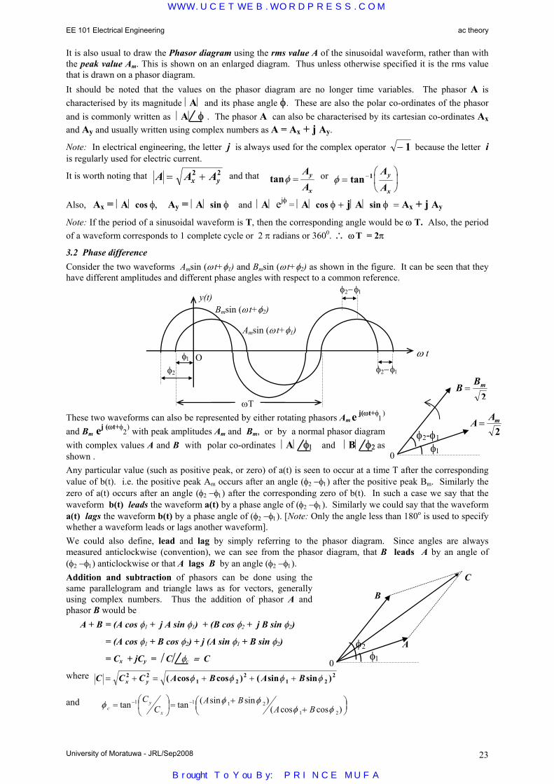
EE 101 Electrical Engineering ac theory
University of Moratuwa - JRL/Sep2008 23
It is also usual to draw the Phasor diagram using the rms value A of the sinusoidal waveform, rather than with the peak value Am. This is shown on an enlarged diagram. Thus unless otherwise specified it is the rms value that is drawn on a phasor diagram. It should be noted that the values on the phasor diagram are no longer time variables. The phasor A is characterised by its magnitude A and its phase angle φ. These are also the polar co-ordinates of the phasor and is commonly written as A φ . The phasor A can also be characterised by its cartesian co-ordinates Ax and Ay and usually written using complex numbers as A = Ax + j Ay.
Note: In electrical engineering, the letter j is always used for the complex operator − 1 because the letter i is regularly used for electric current.
It is worth noting that A A Ax y= +2 2 and that tanφ =AA
y
x
or φ =
−tan 1 A
Ay
x
Also, Ax = A cos φ, Ay = A sin φ and A ejφ = A cos φ + jA sin φ = Ax + j Ay Note: If the period of a sinusoidal waveform is T, then the corresponding angle would be ω T. Also, the period of a waveform corresponds to 1 complete cycle or 2 π radians or 3600. ∴ ω T = 2π
3.2 Phase difference Consider the two waveforms Amsin (ω t+φ1) and Bmsin (ω t+φ2) as shown in the figure. It can be seen that they have different amplitudes and different phase angles with respect to a common reference.
These two waveforms can also be represented by either rotating phasors Am e j(ωt+φ1
) and Bm ej (ωt+φ
2) with peak amplitudes Am and Bm, or by a normal phasor diagram
with complex values A and B with polar co-ordinates A φ1 and B φ2 as shown . Any particular value (such as positive peak, or zero) of a(t) is seen to occur at a time T after the corresponding value of b(t). i.e. the positive peak Am occurs after an angle (φ2 −φ1) after the positive peak Bm. Similarly the zero of a(t) occurs after an angle (φ2 −φ1) after the corresponding zero of b(t). In such a case we say that the waveform b(t) leads the waveform a(t) by a phase angle of (φ2 −φ1). Similarly we could say that the waveform a(t) lags the waveform b(t) by a phase angle of (φ2 −φ1). [Note: Only the angle less than 180o is used to specify whether a waveform leads or lags another waveform]. We could also define, lead and lag by simply referring to the phasor diagram. Since angles are always measured anticlockwise (convention), we can see from the phasor diagram, that B leads A by an angle of (φ2 −φ1) anticlockwise or that A lags B by an angle (φ2 −φ1). Addition and subtraction of phasors can be done using the same parallelogram and triangle laws as for vectors, generally using complex numbers. Thus the addition of phasor A and phasor B would be A + B = (A cos φ1 + j A sin φ1) + (B cos φ2 + j B sin φ2)
= (A cos φ1 + B cos φ2) + j (A sin φ1 + B sin φ2)
= Cx + jCy = C φc = C
where C C C A B A Bx y= + = + + +2 21 2
21 2
2( cos cos ) ( sin sin )φ φ φ φ
and
++=
= −−
)coscos()sinsin(tantan
21
2111
φφφφφ BA
BAC
Cx
yc
φ1 O φ2
y(t)
ω t
Amsin (ω t+φ1)
Bmsin (ω t+φ2)
ωT
φ2− φ1
φ2− φ1
φ1 0
A Am=2φ2-φ1
BBm=
2
φ10
φ2
B
C
A
WWW.UCETWEB.WORDPRESS.COM
Brought To You By: PRINCE MUFA

EE 101 Electrical Engineering ac theory
University of Moratuwa - JRL/Sep2008 24
Example Find the addition and the subtraction of the two complex numbers given by 10 30o and 25 48o.
Addition = 10 30o + 25 48o = 10(0.8660 + j 0.5000) + 25(0.6691 + j 0.7431)
= (8.660 + 16.728) + j (5.000 + 18.577) = 25.388 + j 23.577 = 34.647 42.9o
Subtraction = 10 30o − 25 48o = (8.660 − 16.728) + j (5.000 − 18.577) = − 8.068 − j 13.577 = 15.793 239.3o
Multiplication and division of phasors is most easily done using the polar form of complex numbers. Thus the multiplication of phasor A and phasor B would be
A * B = A φ1 * B φ2 = A e jφ1 ∗ B e jφ2 = A*B e j(φ1+ φ
2) = A*B φ1+ φ2 =C φc
where C = A*B and φc = φ1+ φ2
In a similar way, it can be easily seen that for division
C = A/B and φc = φ1− φ2
Thus, whenever we need to do addition and subtraction, we use the cartesian form of complex numbers, whereas for multiplication or division we use the polar form.
Example Find the multiplication and the division of the two complex numbers given by 10 30o and 25 48o.
Multiplication = 10 30o * 25 48o = 250 78o
Division = 10 30o ÷ 25 48o = 0.4 −18o
3.3 Currents and voltages in simple circuit elements 3.3.1 Resistor
for a sinusoid, consider i(t) =Real part of [ Im e(jωt+θ) ] or Im cos (ωt+θ) ∴v(t) = Real [R. Im e(jωt+θ) ] = Real [Vm. e(jωt+θ)]
or v(t) = R.Im cos (ωt+θ) = Vm cos (ωt+θ )
∴Vm = R.Im and Vm/√2 = R.Im/√2
i.e. V = R . I
Note: V and I are rms values of the voltage and current and no additional phase angle change has occurred in the resistor .
Note also that the power dissipated in the resistor R is equal to R . I 2 = V . I 3.3.2 Inductor
for a sinusoid, consider i(t) =Real part of [ Im e(jωt+θ) ] or Im cos (ωt+θ) ∴v(t) = Real [L. d
dt Im e(jωt+θ) ] = Real [L. jω. Im ej(ωt+θ) ] = Real [j Vm ej(ωt+θ) ]
or v(t) = L. ddt
Im cos (ω t+θ) = −L.ω.Im sin (ωt+θ) = L. ω.Im cos (ωt+θ+π/2)
=Vm cos (ωt+θ+π/2)
∴Vm = ωL.Im and Vm/√2 = ωL.Im/√2
It can be seen that the rms magnitude of voltage is related to the rms magnitude of current by the multiplying factor ωL. It also seen that the voltage waveform leads the current waveform by 90o or π/2 radians or that the current waveform lags the voltage waveform by 90o for an inductor .
Thus it is usual to write the relationship as V = jωL.I or V = ω L.I 90ο The impedance Z of the inductance may thus be defined as jω L , and V = Z . I corresponds to the generalised form of Ohm’s Law. Remember also that the power dissipation in a pure inductor is zero, as energy is only stored and as there is no resistive part in it, but that the product V . I is not zero.
L
v (t)
i (t)
R
V
I
j ωL
V
I
R
v (t)
i (t)
v t L d i tdt
( ) ( )=
v(t) = R.i(t)
O ω t
Vmsin ω t
Imcos ω t
ωT
π/2
O ω t
Vmcos ω t
Imcos ω t
ωT
V
I
O
Phasor diagram
V I O
Phasor diagram
WWW.UCETWEB.WORDPRESS.COM
Brought To You By: PRINCE MUFA
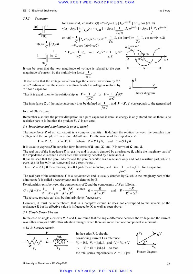
EE 101 Electrical Engineering ac theory
University of Moratuwa - JRL/Sep2008 25
3.3.3 Capacitor for a sinusoid, consider i(t) =Real part of [ Im ej(ωt+θ) ] or Im cos (ωt+θ)
v(t) = Real [ 1C
I e dtmj t( ) .ω θ+∫ ] = Real [ 1
C j. ω. Im e(jωt+θ) ] = Real [ 1
jVm e(jωt+θ) ]
or v(t) = 1C
I t dtm cos( ).ω θ+∫ = 1Cω
.Im sin (ωt+θ) = 1Cω
.Im cos (ωt+θ−π/2)
=Vm cos (ωt+θ−π/2)
∴Vm = 1ω C
.Im and Vm/√2 = 1ω C
.Im/√2
It can be seen that the rms magnitude of voltage is related to the rms magnitude of current by the multiplying factor 1
ω C.
It also seen that the voltage waveform lags the current waveform by 90o or π/2 radians or that the current waveform leads the voltage waveform by 90o for a capacitor.
Thus it is usual to write the relationship as V = 1j Cω
.I or V = 1ω C
.I 90ο
The impedance Z of the inductance may thus be defined as 1j Cω
, and V = Z . I corresponds to the generalised
form of Ohm’s Law.
Remember also that the power dissipation in a pure capacitor is zero, as energy is only stored and as there is no resistive part in it, but that the product V . I is not zero.
3.4 Impedance and Admittance in an a.c. circuit
The impedance Z of an a.c. circuit is a complex quantity. It defines the relation between the complex rms voltage and the complex rms current. Admittance Y is the inverse of the impedance Z. V = Z . I, I = Y . V where Z = R + j X, and Y = G + j B
It is usual to express Z in cartesian form in terms of R and X, and Y in terms of G and B. The real part of the impedance Z is resistive and is usually denoted by a resistance R, while the imaginary part of the impedance Z is called a reactance and is usually denoted by a reactance X. It can be seen that the pure inductor and the pure capacitor has a reactance only and not a resistive part, while a pure resistor has only resistance and not a reactive part. Thus Z = R + j 0 for a resistor, Z = 0 + jωL for an inductor, and Z = 1
j Cω = 0 − j 1
ω Cfor a capacitor.
The real part of the admittance Y is a conductance and is usually denoted by G, while the imaginary part of the admittance Y is called a susceptance and is denoted by B. Relationships exist between the components of Z and the components of Y as follows.
G j B YZ R j X
R j XR X
+ = = =+
=−+
1 12 2
so that G RR X
B XR X
=+
=−
+2 2 2 2, and
The reverse process can also be similarly done if necessary.
However, it must be remembered that in a complex circuit, G does not correspond to the inverse of the resistance R but its effective value is influenced by X as well as seen above.
3.5 Simple Series Circuits
In the case of single elements R, L and C we found that the angle difference between the voltage and the current was either zero, or ± 90o. This situation changes when there are more than one component in a circuit.
3.5.1 R-L series circuit
In the series R-L circuit, considering current I as reference VR = R.I, VL = jωL.I, and V = VR + VL ∴ V = (R + jωL).I so that the total series impedance is Z = R + jωL
v tC
i t dt( ) ( ).= ∫1
O ω t Vmsin ω t
Imcos ω t
ωT
π/2
R jωL I
VR VL
V
C
v (t)
i (t)
1j Cω
V
I
φ
V VL
VR I Phasor diagram
VL
V
I
O Phasor diagram
WWW.UCETWEB.WORDPRESS.COM
Brought To You By: PRINCE MUFA

EE 101 Electrical Engineering ac theory
University of Moratuwa - JRL/Sep2008 26
The above phasor diagram has been drawn with I as reference. [i.e. I is drawn along the x-axis direction]. The current was selected as reference in this example, because it is common to both the resistance and the inductance and makes the drawing of the circuit diagram easier. In this diagram, the voltage across the resistor VR is in phase with the current, where as the voltage across the inductor VL is 90o leading the current. The total voltage V is then obtained by the phasor addition (similar to vector addition) of VR and VL.
If the total voltage was taken as the reference, the diagram would just rotate as shown. In this diagram, the current is seen to be lagging the voltage by the same angle that in the earlier diagram the voltage was seen to be leading the current. VL has been drawn from the end of VR rather than from the origin for ease of obtaining the resultant V from the triangular law.
In an R-L circuit, the current lags the voltage by an angle less than 90o and the circuit is said to be inductive.
Note that the power dissipation can only occur in the resistance in the circuit and is equal to R . I 2 and that this is not equal to product V . I for the circuit.
3.5.2 R-C series circuit
In the series R-C circuit,
VR = R.I, VC = 1j Cω
. I = − j 1ω C
. Ι
and V = VR + VC
∴ V = (R + 1j Cω
).I so that the total series impedance is Z = R + 1j Cω
The phasor diagrams has been drawn first with current I as reference and then with voltage V as reference.
In an R-C circuit, the current leads the voltage by an angle less than 90o and the circuit is said to be capacitive.
Note that the power dissipation can only occur in the resistance in the circuit and is equal to R . I 2 and that this is not equal to product V . I for the circuit.
3.5.3 L-C series circuit
In the series L-C circuit,
VL = jωL.I, VC = 1j Cω
.I = − j 1ω C
and V = VL + VC
∴ V = (jωL + 1j Cω
).I so that the total series impedance is Z = jωL + 1j Cω
= jωL − j 1ω C
It is seen that the total impedance is purely reactive, and that all the voltages in the circuit are inphase but perpendicular to the current. The resultant voltage corresponds to the algebraic difference of the two voltages VL and VC and the direction could be either up or down depending on which voltage is more.
When ωL = 1ω C
the total impedance of the circuit becomes zero, so that the circuit current for a given supply
voltage would become very large (only limited by the internal impedance of the source). This condition is known as series resonance. In an L-C circuit, the current either lags or leads the voltage by an angle equal to 90o and the resultant circuit is either purely inductive or capacitive.
Note that no power dissipation can occur in the circuit and but that the product V . I for the circuit is non zero.
3.5.4 R-L-C series circuit
In the series R-L-C circuit,
VR = R.I, VL = jωL.I, VC = 1j Cω
. I = − j 1ω C
. Ι
and V = VR +VL + VC
∴ V = (R + jωL + 1j Cω
).I so that the total series impedance is Z = R +jωL + 1j Cω
= R + j(ωL − 1ω C
)
R 1
j Cω
I
VR VC
V
1j Cω
jωL I
VC VL
V
Phasor diagram V VC
VR I
R jωL I
VR VL
V 1
j Cω
VC
φ
Phasor diagram
V
VL
VR I
φ
φ V
VL
VR I
Phasor
V
VC
VL
I or VC
VL
I V
WWW.UCETWEB.WORDPRESS.COM
Brought To You By: PRINCE MUFA
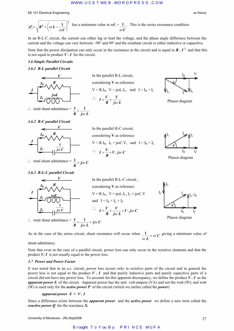
EE 101 Electrical Engineering ac theory
University of Moratuwa - JRL/Sep2008 27
Z R LC
= + −
2
21ω
ω has a minimum value at ωL = 1
ω C. This is the series resonance condition.
In an R-L-C circuit, the current can either lag or lead the voltage, and the phase angle difference between the current and the voltage can vary between −90o and 90o and the resultant circuit is either inductive or capacitive.
Note that the power dissipation can only occur in the resistance in the circuit and is equal to R . I 2 and that this is not equal to product V . I for the circuit.
3.6 Simple Parallel Circuits
3.6.1 R-L parallel Circuit
In the parallel R-L circuit,
considering V as reference
V = R.IR, V = jωL.IL, and I = IR + IL
∴ I VR
Vj L
= +ω
∴ total shunt admittance = 1 1R j L
+ω
3.6.2 R-C parallel Circuit
In the parallel R-C circuit,
considering V as reference
V = R.IR, IC = jωC.V, and I = IR + IL
∴ I VR
V j C= + . ω
∴ total shunt admittance = 1R
j C+ ω
3.6.3 R-L-C parallel Circuit
In the parallel R-L-C circuit ,
considering V as reference
V = R.IR, V = jωL.IL, IC = jωC.V
and I = IR + IL + IC
∴ I VR
Vj L
V j C= + +ω
ω.
∴ total shunt admittance = 1 1R j L
j C+ +ω
ω
As in the case of the series circuit, shunt resonance will occur when 1ω
ωL
C= giving a minimum value of
shunt admittance.
Note that even in the case of a parallel circuit, power loss can only occur in the resistive elements and that the product V. I is not usually equal to the power loss.
3.7 Power and Power Factor
It was noted that in an a.c. circuit, power loss occurs only in resistive parts of the circuit and in general the power loss is not equal to the product V . I and that purely inductive parts and purely capacitive parts of a circuit did not have any power loss. To account for this apparent discrepancy, we define the product V . I as the apparent power S of the circuit. Apparent power has the unit volt-ampere (VA) and not the watt (W), and watt (W) is used only for the active power P of the circuit (which we earlier called the power)
apparent power S = V . I
Since a difference exists between the apparent power and the active power we define a new term called the reactive power Q for the reactance X.
Phasor diagram
φ
I IL
IR V
IL
Phasor diagram
φ
I IL
IR V
IL R
1j Cω
IR
V
IC
I
R
jωL
IR
V
IL
I
R
1j Cω
IR
V
IL I
IC
jωL
Phasor diagram
φ
I IL+IC
IR V
IC
IL
WWW.UCETWEB.WORDPRESS.COM
Brought To You By: PRINCE MUFA

EE 101 Electrical Engineering ac theory
University of Moratuwa - JRL/Sep2008 28
The instantaneous value of power p(t) is the product of the instantaneous value of voltage v(t) and the instantaneous value of current i(t).
i.e. p(t) = v(t) . i(t)
If v(t) = Vm cos ω t and i(t) = Im cos (ω t − φ),
where the voltage has been taken as reference and the current lags the voltage by a phase angle φ
then p(t) = Vm cos ω t . Im cos (ω t − φ) = Vm Im . . 2 cos ω t . cos (ω t − φ)
= Vm Im [cos (2ω t − φ) + cos φ]
It can be seen that the waveform of power p(t) has a sinusoidally varying component and a constant component.
Thus the average value of power (active power) P would be given by the constant value ½ Vm Im cos φ.
active power P = ½ Vm Im cos φ = V Im m
2 2. .cosφ = V . I cos φ
The term cos φ is defined as the power factor, and is the ratio of the active power to the apparent power.
Note that for a resistor, φ = 0o so that P = V . I
and that for an inductor, φ = 90o lagging (i.e. current is lagging the voltage by 90o) so that P = 0
and that for an capacitor, φ = 90o leading (i.e. current is leading the voltage by 90o) so that P = 0
For combinations of resistor, inductor and capacitor, P lies between V. I and 0
For an inductor or capacitor, V. I exists although P = 0. For these elements the product V. I is defined as the reactive power Q. This occurs when the voltage and the current are quadrature (90o out of phase). Thus reactive power is defined as the product of voltage and current components which are quadrature. This gives
reactive power Q = V. I sin φ
Unlike in the case of inphase, where the same direction means positive, when quantities are in quadrature there is no natural positive direction. It is usual to define inductive reactive power when the current is lagging the voltage and capacitive reactive power when the current is leading the voltage. It is worth noting that inductive reactive power and capacitive reactive power have opposite signs.
Although reactive power does not consume any energy, it reduces the power factor below unity. When the power factor is below unity, for the same power transfer P the current required becomes larger and the power losses in the circuit becomes still larger (power loss ∝ I2). This is why supply authorities encourage the industries to improve their power factors to be close to unity.
3.8 Three Phase Power
As you already know, to transmit power using single phase ac, we need two wires. Of course you may have an earth wire for protection, but this wire does not usually carry any current. You may also have seen that distribution lines usually have 4 wires. What are these 4 wires ? It is the three phase wires and the neutral wire.
3.8.1 Balanced Three Phase Now why do you need three phase wires ? This is in order to make our transmission efficient. You are already aware that if we have three equal forces at angles of 120o to each other, if we use the triangular law we get an equilateral triangle in which the resultant force is zero. A similar thing happens in three phase except that we have phasors instead of vectors. That is, we have 3 voltages (or currents) which are equal in magnitude but differing in phase angle by 120o from each other.
Vm Im cos φ
p(t)
t T
v(t)
i(t)
t
p(t)
p(t)
current lagging voltage by angle φ inphase quadrature
WWW.UCETWEB.WORDPRESS.COM
Brought To You By: PRINCE MUFA

EE 101 Electrical Engineering ac theory
University of Moratuwa - JRL/Sep2008 29
Three phase waveforms-100
-50
0
50
100
0 π/ 2 π 3π/ 2 2π
angle (rad)
current R phase Y phase B phase
If the R phase is taken as reference and drawn vertical (reference need not always be drawn horizontally), then the three phases would have the phasor diagram shown. If vR(t) = Vm cos ω t, then vY(t) = Vm cos (ω t −2π/3) and vB(t) = Vm cos (ω t +2π/3) It can easily be seen that the addition of these three waveforms at any instant is zero. This is not only true for balanced three phase voltages, but for balanced three phase currents. Thus if we have a balanced three phase system of currents, then their addition would become zero, and no neutral wire would be required. However in practice, three phase currents are never perfectly balanced and the neutral wire would carry the unbalance.
If VR, VY, and VB are the r.m.s.voltages of the three phases with respect to the neutral, then they are normally called the phase voltages. The voltage between any two phase wires (or lines) is called the line voltage.
As can be seen from the diagram, the magnitude of the line voltage is √3 times the phase voltage for a balanced system. In a three phase system, it is always the r.m.s. line voltage that is specified, unless otherwise specified. For example in the domestic supply, in single phase we say that the voltage is 230 V and in three phase we say that the voltage is 400 V (~ 230 × √3).
If Vp is the phase voltage magnitude, VR = Vp ∠0, VY = Vp ∠-2π/3, VB = Vp ∠2π/3 .
The Line voltage magnitude will be √3×Vp = VL and the line voltages will be VRY = VL ∠π/6,
VYB = VL ∠(-2π/3+π/6) = VL ∠-π/2 , VBR = VL ∠(2π/3+π/6)= VL ∠5π/6.
Balanced loads may be connected either in star or delta as shown.
A balanced star connected load can be converted to an equivalent delta and the other way round as well. In such a case it can be shown that
ZD = 3 ZS
It can also be shown that the total three phase power in a star connected load, or delta connected load can be expressed in terms of the line quantities as
P = √3 VL IL cos φ
where cos φ is the power factor of the load, VL is the line voltage and IL is the line current.
The reactive power in a three phase circuit may be similarly defined as
Q = √3 VL IL sin φ
and the apparent power in a three phase circuit may be defined as
S = √3 VL IL
Note: In both the single phase circuit as well as the three phase circuit,
S2 = P2 + Q2 and tan φ = Q/P
Since the magnitudes of the three phases are equal (for both voltage and current) in a balanced three phase system, it is sufficient to calculate the quantities for one of the phases and obtain the others by symmetry.
R
YB
120o
120o
120o
ZS
ZS ZS
ZD
ZD
ZD
P
Q S
φ
WWW.UCETWEB.WORDPRESS.COM
Brought To You By: PRINCE MUFA

EE 101 Electrical Engineering ac theory
University of Moratuwa - JRL/Sep2008 30
Example
A 3 phase, 12 kW balanced load at a lagging power factor of 0.8 is supplied from a 3 phase, 400V, 50 Hz supply. Determine the line current in magnitude and phase relative to the supply voltage, the apparent power and the reactive power drawn.
P = 12 kW, VL = 400V, cos φ = 0.8 lag, P = √3 VL IL cos φ, i.e. 12000 = √3 × 400 × IL × 0.8
∴ IL = 21.65 A, φ = cos-1(0.8) = 36.87o. i.e. IL = 21.65 ∠-36.87o A.
Apparent power = √3VL IL = √3 × 400 × 21.65 = 15000 = 15 kVA.
Reactive power = √3 VL IL sin φ = √3 × 400 × 21.65 × sin (36.87o) = 9000 = 9 k var
3.8.1 Unbalanced three phase systems
Unbalanced three phase systems would consist of either star connected or delta connected sources which need not be balanced and an unbalanced star connected or delta connected load. Such systems cannot be solved using one phase of the system, but could be solved using the normal network theorems.
3.9 Power factor correction
Since most practical loads are inductive in nature (as they have coils rather than capacitors), the power factor can be improved by using capacitors across the load. They may be either connected in star or delta.
A pure capacitor affects only the reactive power and not the active power.
Example
In the above example a delta connected bank of capacitors are used to improve the power factor to 0.95 lag. What should be the value of the required capacitors.
New power factor = 0.95 lag. ∴ new power factor angle = cos-1 (0.95) = 18.19o
The active power of the load is unchanged by the capacitor bank, ∴ P = 12000 W
∴ new reactive power = P tan φ = 12000 × tan (18.19o) = 3944 = 3.944 k var
∴ reactive power supplied from capacitor bank = 9000 - 3944 = 5056 = 5.056 k var. Each of the 3 capacitors in the delta connected bank must supply = 5.056/3 = 1.685 k var. Since they are connected in delta, each would get a voltage of 400 V.
∴ VL2 C ω = 4002 × C × 2 π × 50 = 1685
∴ C = 33.5 × 10-6 = 33.5 µF. If the capacitors had been connected in star, then the reactive power would still have been the same, but the voltage across each would have been 400/√3 and the value of each capacitor would be
Vp2 C' ω = (400/√3)2 × C' × 2 π × 50 = 1685
∴ C' = 100.6 × 10-6 = 100.6 µF.
WWW.UCETWEB.WORDPRESS.COM
Brought To You By: PRINCE MUFA

EE 101 Electrical Engineering Electrostatics and Electromagnetics
University of Moratuwa - JRL/Sep2008 31
4.1 Electrostatic Theory
Electrostatics is based on two theories - Gauss’s Law and the Inverse Square Law
4.1.1 Gauss’s Law
Gauss’s law states that the total electric flux coming out of a closed surface is equal to the algebraic sum of the charge enclosed .
ψ = Σ q
[The Unit of both electric flux ψ and charge q is the coulomb (C)] Electric flux density D is the amount of electric flux coming out per unit area normal to the direction of the flux. [Unit: coulomb per meter2 or C/m2]
D = ψ/A Consider an imaginary sphere of radius r surrounding a point charge q as shown. Electric flux ψ = q will go out equally in all directions through a surface area of 4π r
2, normal to this surface.
∴ electric flux density at radius r is D qrr =
4 2π
4.1.2 Inverse Square Law The Inverse square law of electrostatics states that the force exerted by two point charges, on each other, is proportional to the product of their charges and inversely proportional to the square of the distance between them.
The Electric field ξ at a point is defined as the force exerted on a unit positive charge placed at that point.
If the field is produced by a charge q1, then the force acting on a charge q2 = +1 will beξr kq
r=
×. 1
21
at a
distance r from the charge.
It can be seen that the electric flux density Dr and the electric field ξ r are both proportional to q and inversely proportional to r2 and are thus proportional to each other.
The permittivity ε of the medium is thus defined as their ratio. i.e. D = ε ξ . [Unit of permittivity is farad per meter or F/m] Thus the constant k in the inverse square law equation becomes 1/k = 4π ε and the inverse square law can be
stated as Fq q
d= 1 2
24.
π ε.
The permittivity of free space is ε0 = 8.854 × 10⁻¹² F/m. It is usual to express the permittivity of a medium as a relative value by comparing it with that of free space. Thus the relative permittivity (also called dielectric constant) εr of a material is defined using the relationship εr = ε/ε0 or ε = ε0 εr. [εr is always greater than 1.] [Relative permittivity being a number, has no dimension and is thus without a unit]. [In practice the relative permittivity of air which is 1.00060 is taken as unity or same of that of free space] Electric potential difference between two points A and B is (usually) defined as the work that must be done, against the forces of an electric field, in moving a unit positive charge from point A to point B. The change in energy dW in moving a unit positive charge an elemental distance dx in the direction of the force F would be F. dx . The corresponding change in potential would be an elemental value − dV.
The force acting on a unit positive charge, by definition, is the electric field ξ.
∴ ξ . dx = - dV or ξ = −dVdx
[Unit for electric field is volt per meter or V/m]
4.1.3 Capacitance of a dielectric (or insulating material) is the ability to store charge when placed between two electrodes across which a potential difference has been applied. Thus capacitance is defined as the ratio of the amount of charge transferred to the applied potential difference. i.e. C = q/V or q = C . V [Unit of capacitance is the farad (F)]
electric flux ψ
electric charges q1 q4 q2 q3
dq1 q2
F q qd
k q qd
∝ =1 22
1 22
. . .
q r
WWW.UCETWEB.WORDPRESS.COM
Brought To You By: PRINCE MUFA

EE 101 Electrical Engineering Electrostatics and Electromagnetics
University of Moratuwa - JRL/Sep2008 32
Parallel plate capacitor Simplest form of capacitor is the parallel plate capacitor where the dielectric (permittivity ε) of thickness d separates two parallel electrodes of cross-section area A.
From Gauss’s theorem, ψ = q
∴ D = ψ /Α = q/A, also D = ε ξ = q
and for a uniform field, ξ = − dV/dx = V/d
∴ D Vd
qA
= =ε , C qV
Ad
= =ε
Cylindrical capacitor A common form of capacitance obtained, especially with co-axial cables, is the case where both electrodes are cylindrical and have the same axis .
From Gauss’s theorem, ψ = q
∴ Dr = ψ /Α = q/2π r l, also D = ε ξ = q/A and ξ = − dV/dr
∴ − =dVdr
qrl2π ε
Integration gives rdr
lqdV
r
r
V
V∫∫ =−2
1
2
12 επ , − + =
V V
ql
rr1 22
12π εln
∴ [ ]
C lr r
=2
2 1
π εln /
4.1.4 Energy stored in an electric field
Consider a parallel plate capacitor of cross-section area A and spacing of electrodes d
Energy stored in a capacitor = v i dt v dq v C dv Cv⋅ ⋅ = ⋅ = ⋅ ⋅ =∫∫∫ 12
2
Energy stored in a unit volume in an electric field = v dq v dqd A
d D D d D⋅=
⋅= ⋅ = ⋅∫ ∫ ∫ ∫volume .
ξε
= = ⋅12
212
D Dε
ξ J/m3
4.1.5 Force exerted in an electric field
Consider moving the electrodes of a parallel plate capacitor so that the spacing changes by dx
change in energy stored = ½ D.ξ × (change in volume) = ½ D.ξ × A. dx Also, change in energy stored = work done = F . dx
∴ F . dx = ½ D.ξ . A. dx or F = ½ D.ξ . A i.e. Force exerted on unit area in an electric field = F/A = ½ D.ξ Ν/m2
4.1.6 Ohm’s Law in an electric field Consider a cylindrical volume in the direction of the current flow, as shown in the figure. Current density in the conducting medium J = I/A
Field in the medium ξ = − dV/dx = V/l for a uniform field
Also, since R = ρl/A and V = R.I, ξ ρ⋅ = ⋅ ⋅l l
AJ A
This gives Ohm’s law for an electric field as ξ = ρ . J or more commonly written as J = σ . ξ
where conductivity σ = 1/ρ
+q
−q
V
A
d
r2
r r1
l
Al
I
V
WWW.UCETWEB.WORDPRESS.COM
Brought To You By: PRINCE MUFA

EE 101 Electrical Engineering Electrostatics and Electromagnetics
University of Moratuwa - JRL/Sep2008 33
4.2 Electromagnetic Theory One of the basic theorems in electromagnetism is the Ampere’s Law which relates, the magnetic field produced by an electric current, to the current passing through a conductor. 4.2.1 Ampere’s Law Ampere’s Law states that the line integral of the magnetic field H taken around a closed path is equal to the total current enclosed by the path.
H d l I⋅ = ∑∫
For a uniform field, H is a constant and we have H . l = Σ I
or if H is constant over sections, with different sections having different H, then Σ H . l = Σ I [Unit of magnetic field is ampere per meter (A/m)] 4.2.2 Magnetomotive force (mmf) Magnetomotive force is the flux producing ability of an electric current in a magnetic circuit. [It is something similar to electromotive force in an electric circuit]. [Unit of magnetomotive force is ampere (A)] - Note: Although some books use the term ampere-turns, it is strictly not correct as turns is not a dimension]
mmf ℑ = Σ I
Consider a coil having N turns as shown. It will link the flux path with each turn, so that
total current linking with the flux would be Σ I = N.I Thus from Ampere’s Law, the mmf produced by a coil of N turns would be N I, and N I = H l.
4.2.3 Field produced by a long straight conductor
If a circular path of radius r is considered around the conductor carrying a current I, then the field Hr along this path would be constant by symmetry.
∴by Ampere’s Law, 1.I = Hr .2π r or H Irr =
2π at a radial distance r from the conductor.
4.2.4 Field produced inside a toroid Consider a toroid (similar to a ring) wound uniformly with N turns. If the mean radius of the magnetic path of the toroid is a, then the magnetic path length would be 2π a, and the total mmf produced would be N I. Thus from Ampere’s Law
magnetic field H NIa
=2π
inside the toroid. [variation of the magnetic field inside the cross section of the
toroid is usually not necessary to be considered and is assumed uniform].
4.2.5 Magnetic flux density
The magnetic field H gives rise to a magnetic flux φ, which has a magnetic flux density B for a given area A. The relationship between B and H is given by the permeability of the medium µ..
B = µ H, where µ = µo µr, µr is the relative permeability and µo is the permeability of free space
µo = 4π × 10-7 H/m [permeability of air is generally taken to be equal to that of free space in practice] [Unit of permeability is henry per meter (H/m)]. [Unit of magnetic flux density is the tesla (T) ]
φ = B.A [Unit of magnetic flux is the weber (Wb)] 4.2.6 Reluctance of a magnetic path A magnetic material presents a Reluctance S to the flow of magnetic flux when an mmf is applied to the magnetic circuit. [This is similar to the resistance shown by an electric circuit when an emf is applied]
Thus mmf = Reluctance × flux or ℑ = S . φ
current magnetic field
current
Flux path
r
I
a I
N turns
toroid
WWW.UCETWEB.WORDPRESS.COM
Brought To You By: PRINCE MUFA
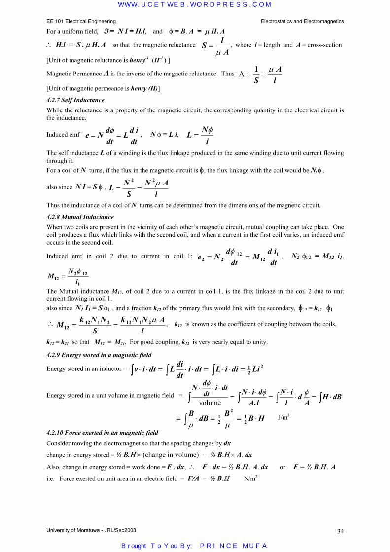
EE 101 Electrical Engineering Electrostatics and Electromagnetics
University of Moratuwa - JRL/Sep2008 34
For a uniform field, ℑ = N I = H.l, and φ = B. A = µ H. A
∴ H.l = S . µ H. A so that the magnetic reluctance S lA
=µ
, where l = length and A = cross-section
[Unit of magnetic reluctance is henry-1 (H-1 ) ]
Magnetic Permeance Λ is the inverse of the magnetic reluctance. Thus Λ = =1S
Al
µ
[Unit of magnetic permeance is henry (H)]
4.2.7 Self Inductance While the reluctance is a property of the magnetic circuit, the corresponding quantity in the electrical circuit is the inductance.
Induced emf e N ddt
L d idt
= =φ , N φ = L i, L N
i=
φ
The self inductance L of a winding is the flux linkage produced in the same winding due to unit current flowing through it. For a coil of N turns, if the flux in the magnetic circuit is φ, the flux linkage with the coil would be N.φ .
also since N I = S φ , L NS
N Al
= =2 2µ
Thus the inductance of a coil of N turns can be determined from the dimensions of the magnetic circuit.
4.2.8 Mutual Inductance When two coils are present in the vicinity of each other’s magnetic circuit, mutual coupling can take place. One coil produces a flux which links with the second coil, and when a current in the first coil varies, an induced emf occurs in the second coil.
Induced emf in coil 2 due to current in coil 1: e Nd
dtM
d idt2 2
1212
1= =φ
, N2 φ12 = M12 i1,
MN
i122 12
1=
φ
The Mutual inductance M12, of coil 2 due to a current in coil 1, is the flux linkage in the coil 2 due to unit current flowing in coil 1. also since N1 I1 = S φ1 , and a fraction k12 of the primary flux would link with the secondary, φ12 = k12 . φ1
∴ M k N NS
k N N Al12
12 1 2 12 1 2= =µ , k12 is known as the coefficient of coupling between the coils.
k12 = k21 so that M12 = M21. For good coupling, k12 is very nearly equal to unity.
4.2.9 Energy stored in a magnetic field
Energy stored in an inductor = v i dt L didt
i dt L i di Li⋅ ⋅ = ⋅ ⋅ = ⋅ ⋅ =∫∫∫ 12
2
Energy stored in a unit volume in magnetic field = N d
dti dt N i d
A lN i
ld
AH dB
⋅ ⋅ ⋅=
⋅ ⋅=
⋅⋅ = ⋅∫ ∫ ∫ ∫
φφ φ
volume .
= ⋅ = = ⋅∫B dB B B Hµ µ
12
212
J/m3
4.2.10 Force exerted in an magnetic field
Consider moving the electromagnet so that the spacing changes by dx
change in energy stored = ½ B.Η × (change in volume) = ½ B.Η × A. dx
Also, change in energy stored = work done = F . dx, ∴ F . dx = ½ B.Η . A. dx or F = ½ B.Η . A i.e. Force exerted on unit area in an electric field = F/A = ½ B.Η Ν/m2
WWW.UCETWEB.WORDPRESS.COM
Brought To You By: PRINCE MUFA

University of Moratuwa – JRL/Sep2008 35
5.0 Electrical Measurements
In order to quantify statements, measurements need to be made. Without measurements only qualitative statements may be made. Measurements may be made either by comparison with a reference quantity of the same kind or by calculation using known quantities of other types. For example, a resistance may be determined by comparison with a known resistance, or it may be determined by the measurement of voltage, current and the law relating resistance, voltage and current.
Applications: Electrical measurements are not restricted to the measurement of electrical quantities such as current, voltage, power and resistance but also non electrical quantities such as speed (tachometer), temperature (thermocouple), pressure (strain gauge), and a host of other quantities. Devices that convert one form of energy to another form for measurement and control, such as above, are known as transducers.
5.1 Accuracy of Measurements
The accuracy need for a measurement depends on the application. For example if we were measuring time using a watch, we would like it not to have to be reset more than once a month at the most. Maybe an error of 1 minute per month may be considered acceptable. [i.e. 1 minute in 30×24×60 minutes or 43,200. i.e. an accuracy of 1 in 43,200 or about 0.0023 %]. On the other hand, a one hour lecture might actually take about 1 hour ± 5 minute [i.e. 5 minute tolerance in 60 minutes or 1 in 12 or 8.33 %]
Accuracy also depends on whether a null deflection method is used (bridge method) or a direct deflection method is used. With a null deflection method higher accuracy is obtained, as the error may be successively reduced, but it is obviously time consuming. This is similar to the use of a knife-edge balance (null deflection) or a spring balance (direct deflection) to weigh something.
5.2 Wheatstone Bridge
The simple 4 arm Wheastone Bridge is a null deflection method.
The detector (or galvanometer) is made more and more sensitive near the balance point, where the detector current becomes zero and the potential difference across the detector also becomes zero. Under this condition, using potential divider action, it can be easily shown that
RR
RR
1
2
3
4=
It must be noted that the balance condition of the bridge does not depend on the source voltage E, nor on the detector impedance. At balance, if three of the resistances are accurately known, the remaining resistance will also be calculated to the same accuracy. For good sensitivity, all 4 arms should have similar values of resistance.
The principle of the Wheatstone Bridge can also be extended to a.c. bridges having inductances and capacitances in addition to resistances. In this case the balance condition is a complex equation and the source would be an a.c. source.
ZZ
ZZ
1
2
3
4=
Bridges are mostly used when accurate measurements are required such as in calibrating an indicating instrument.
Indicating Instruments
Unlike null deflection techniques, which require a number of steps in the balance process, indicating instruments give the reading directly. They may be either analogue or digital. Analogue instruments give a continuous range of values, where as in a digital instrument only an exact number appears.
Analogue meters may be direct deflecting (such as an ammeter or voltmeter), integrating (such as an energy meter) or recording (such as a graph plotter).
0 2 1. 3 5
D E
R1 R3
R2 R4
Digital Meter Analogue Meter
0
50
100
WWW.UCETWEB.WORDPRESS.COM
Brought To You By: PRINCE MUFA

EE 101 Electrical Engineering Electrical Measurements
University of Moratuwa - JRL/Oct2001 36
5.3 Principle of operation of analogue deflecting meters Analogue meters show a particular deflection for a given input quantity. For this to happen, there are three main torques (rotary type of deflection) or forces (linear type). These are (a) the deflecting torque, (b) the controlling torque and (c) the damping torque. The deflecting torque is produced by the measured quantity or a value proportional to it. This causes the pointer or needle to move away from the zero position. However, unless there is a balancing torque, the pointer will continue to move and increase the deflection. This is controlled by a controlling force, which is most commonly produced by a spring (where the torque is proportional to the deflection from the initial position). As in any system, unless damping is provided, the two forces would cause the needle to oscillate about the final position making reading very difficult. Thus damping is provided, which does not affect the final position, but reduces the over swing making the final position to be achieved quickly. 5.3.1 Principle types of analogue meters The principle types of analogue meters in common use are the (a) permanent magnet moving coil meters or commonly referred to as moving coil instruments, (b) moving iron meters, (c) dynamometer type moving coil meters, (d) electrostatic meters and (e) induction type meters. (a) Permanent magnet moving coil meters In this instrument, a moving coil is suspended between the poles of a permanent magnet. When a current is passed through the coil, the coil becomes an electromagnet and tries to align with the permanent magnet. The deflecting torque becomes proportional to the strength of the electromagnet and hence to the current. A coil spring is used which produces a controlling torque proportional to the deflection. Thus at balance, the deflection becomes proportional to the current. When the current is unidirectional, as with d.c., the deflection would be to one particular side. When the current is varying at a rate which the needle cannot follow, what will be indicated by the meter is the mean value, due to the inertia of the movement. Thus the moving coil meter always measures the mean value or d.c. value of a given waveform. (b) Moving iron meters When a piece of iron is placed in the axis of the magnetic field produced by a coil, magnetism of opposite polarity would be induced in the iron. Since opposite poles attract, it would be attracted towards the coil, independent of the direction of magnetism (hence of the current in the coil). The force of attraction would be proportional to the product of the magnetism caused by the coil and the induced magnetism in the piece of iron. Since the latter is proportional to the former, and the former is proportional to the current in the coil, the force of attraction would be proportional to the square of the current. Thus if a controlling torque is provided by a spring, the deflection at balance would be proportional to the square of the current, or since the movement would normally not be able to respond at the rate at which the supply is alternating due to its inertia, the deflection would be proportional to the mean value of the square of the current. If the square root of this indication is taken, it would correspond to the root mean square value or rms value. This value can be measured for both a.c. and d.c. Thus the moving iron meter always measures the r.m.s. value of a given waveform. (c) Dynamometer type instrument The dynamometer type instrument is also a moving coil instrument. In this case, the permanent magnet is replaced by a pair of fixed coils to give the fixed field.
N S
Pointer
iron cylinder
Pointer
Scale
fixed coil
fixed coil
moving coil
0
150
300
Reading of pointer
time
pivot
F
WWW.UCETWEB.WORDPRESS.COM
Brought To You By: PRINCE MUFA
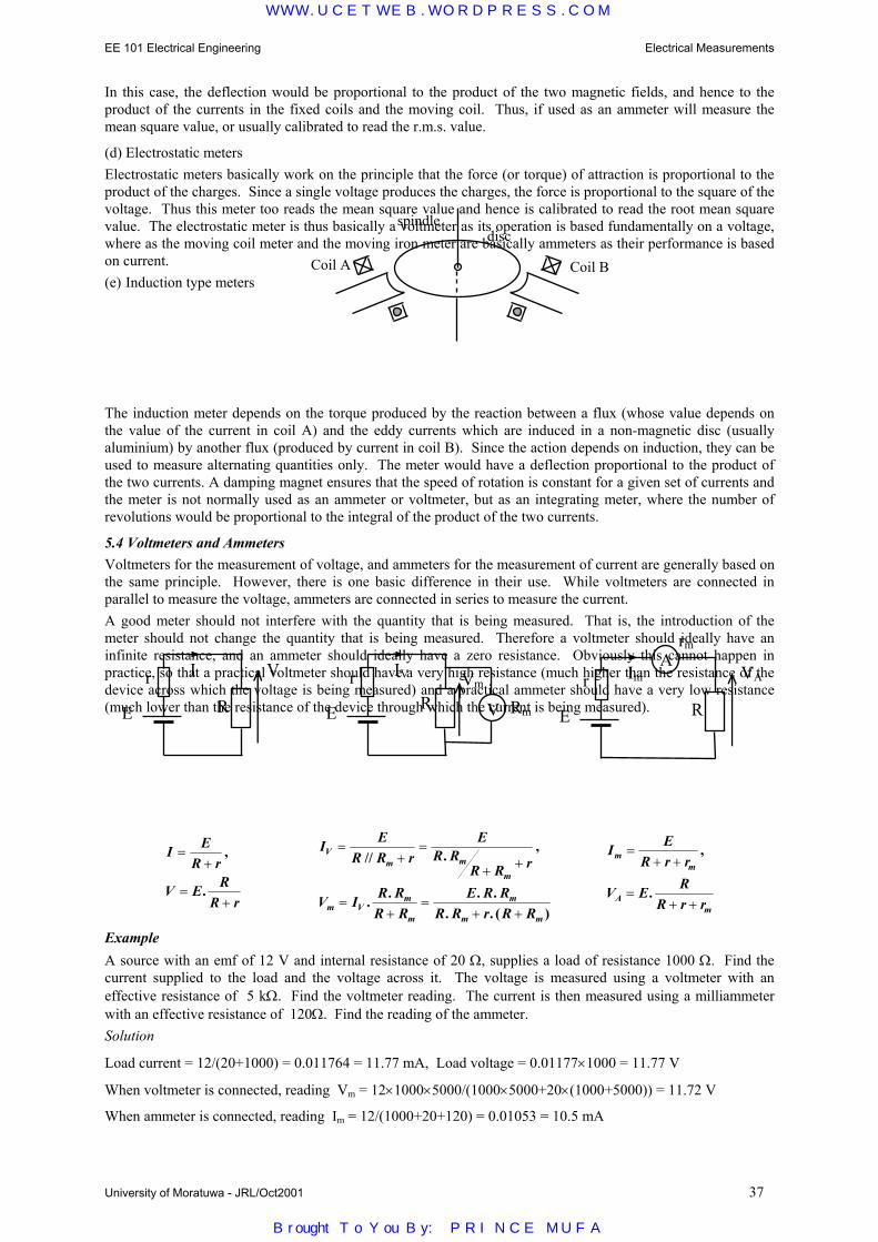
EE 101 Electrical Engineering Electrical Measurements
University of Moratuwa - JRL/Oct2001 37
In this case, the deflection would be proportional to the product of the two magnetic fields, and hence to the product of the currents in the fixed coils and the moving coil. Thus, if used as an ammeter will measure the mean square value, or usually calibrated to read the r.m.s. value.
(d) Electrostatic meters Electrostatic meters basically work on the principle that the force (or torque) of attraction is proportional to the product of the charges. Since a single voltage produces the charges, the force is proportional to the square of the voltage. Thus this meter too reads the mean square value and hence is calibrated to read the root mean square value. The electrostatic meter is thus basically a voltmeter as its operation is based fundamentally on a voltage, where as the moving coil meter and the moving iron meter are basically ammeters as their performance is based on current. (e) Induction type meters
The induction meter depends on the torque produced by the reaction between a flux (whose value depends on the value of the current in coil A) and the eddy currents which are induced in a non-magnetic disc (usually aluminium) by another flux (produced by current in coil B). Since the action depends on induction, they can be used to measure alternating quantities only. The meter would have a deflection proportional to the product of the two currents. A damping magnet ensures that the speed of rotation is constant for a given set of currents and the meter is not normally used as an ammeter or voltmeter, but as an integrating meter, where the number of revolutions would be proportional to the integral of the product of the two currents.
5.4 Voltmeters and Ammeters Voltmeters for the measurement of voltage, and ammeters for the measurement of current are generally based on the same principle. However, there is one basic difference in their use. While voltmeters are connected in parallel to measure the voltage, ammeters are connected in series to measure the current. A good meter should not interfere with the quantity that is being measured. That is, the introduction of the meter should not change the quantity that is being measured. Therefore a voltmeter should ideally have an infinite resistance, and an ammeter should ideally have a zero resistance. Obviously this cannot happen in practice, so that a practical voltmeter should have a very high resistance (much higher than the resistance of the device across which the voltage is being measured) and a practical ammeter should have a very low resistance (much lower than the resistance of the device through which the current is being measured).
I ER r
V E RR r
=+
=+
,
.
I ER R r
ER R
R R r
V I R RR R
E R RR R r R R
Vm m
m
m Vm
m
m
m m
=+
=
+ +
=+
=+ +
// . ,
. . . .. . ( )
I ER r r
V E RR r r
mm
Am
=+ +
=+ +
,
.
Example A source with an emf of 12 V and internal resistance of 20 Ω, supplies a load of resistance 1000 Ω. Find the current supplied to the load and the voltage across it. The voltage is measured using a voltmeter with an effective resistance of 5 kΩ. Find the voltmeter reading. The current is then measured using a milliammeter with an effective resistance of 120Ω. Find the reading of the ammeter. Solution
Load current = 12/(20+1000) = 0.011764 = 11.77 mA, Load voltage = 0.01177×1000 = 11.77 V
When voltmeter is connected, reading Vm = 12×1000×5000/(1000×5000+20×(1000+5000)) = 11.72 V
When ammeter is connected, reading Im = 12/(1000+20+120) = 0.01053 = 10.5 mA
Coil A Coil B
discspindle
r
E R
V I r
E RVm
IV
V Rm r
E R
VAIm A
rm
WWW.UCETWEB.WORDPRESS.COM
Brought To You By: PRINCE MUFA

EE 101 Electrical Engineering Electrical Measurements
University of Moratuwa - JRL/Oct2001 38
It can be seen that the meters do not read the exact value, but as can be seen the error is quite small. Voltmeter usually have a much higher resistance (order of 100 kΩ) and ammeters a much lower resistance (order of 10 mΩ) so that the errors would generally be even smaller.
5.4.1 Measurement of d.c. quantities
Direct quantities are usually measured using the permanent magnet moving coil (p.m.m.c.) instrument. The moving iron (m.i.) instrument and the induction instrument can also be used to measure direct quantities.
5.4.2 Measurement of a.c. quantities
Alternating quantities (r.m.s. value) may be measured using the moving iron (m.i.) instrument and the induction instrument. The permanent magnet moving coil (p.m.m.c.) instrument with a rectifier bridge arrangement can also be used to measure the r.m.s. value of sinusoidal waveforms, since we know the relation between the rectified average value and the r.m.s. value for a sinusoidal waveform. This factor, known as the form factor has a value of 1.1107 for the sinusoidal waveform. Since the rectifier type moving coil meter is meant to measure only the r.m.s. value of sinusoidal waveforms, the meter is calibrated to read 1.11 times the average value rather than the mean value of the rectified waveform. However, when the effective value of other waveforms are measured, there is an error caused.
5.5 Measurement of Power
As instantaneous power is obtained from the product of the instantaneous values of voltage and current, we could use either the dynamometer instrument or the induction type instrument to measure power. One of the coils (called the current coil) has the current passing through it, while the other coil (called the potential coil) has a current, proportional to the voltage, passed through it by having a high series resistance. Due to the inertia of the instrument, the pointer does not respond to the instantaneous value but to the mean value of the product of the currents and hence to the mean value of the instantaneous power. The dynamometer wattmeter can be used to measure both a.c. as well as d.c., while the induction wattmeter can only be used to measure a.c.
Either the current coil can be exactly in series with the current or the potential coil can be exactly in parallel with the voltage. This is shown in the following diagrams.
The average value of the instantaneous power v.i is the active power P that has to be measured. It is seen that neither of the wattmeter connections give the exact reading. In the first connection shown, there is an error of rc.ic
2 corresponding to the power loss in the current coil. The current coil of a wattmeter must thus have an almost zero resistance in order for the error to become negligible [since the current coil is in series, this is similar to the case of the ammeter]. In the second connection shown, there is an error of vp.ip corresponding to the power loss in the potential coil. The potential coil of a wattmeter must thus have an almost infinite resistance in order for the error to become negligible [since the potential coil is in parallel, this is similar to the case of the voltmeter]. The selection of which connection is to be used, is thus based on which gives the smaller loss.
5.6 Measurement of three phase power
ic
Rp v
rc current
coil
potential coil
Load
R
i ip
vp Supply
ic
Rpv
rc current
coil
potential coil
Load
R
i ip
vp Supply
ic = i, vp = v + rc ic, vp = Rp.ip Reading ∝ ic.ip ∝ ic.vp ∝ i.(v + rc.ic) Reading ∝ v.i + rc.ic
2
vp = v, ic = i + ip, vp = Rp.ip Reading ∝ ic.ip ∝ ic.vp ∝ (i + ip).v Reading ∝ v.i + vp.ip
Power = Real VRN.IR* + VYN.IY
* + VBN.IB*
but IR + IY + IB = 0 Kirchoff’s current law
∴P = Real VRN.IR* + VYN.(-IR
*+-IB*) + VBN.IB
*
= Real (VRN− VYN).IR*+ (VBN− VYN).IB
*
= Real VRY.IR*+ VBY.IB
*
= W1 + W2
R
Y
B
Three Phase Load
W1
W2
WWW.UCETWEB.WORDPRESS.COM
Brought To You By: PRINCE MUFA
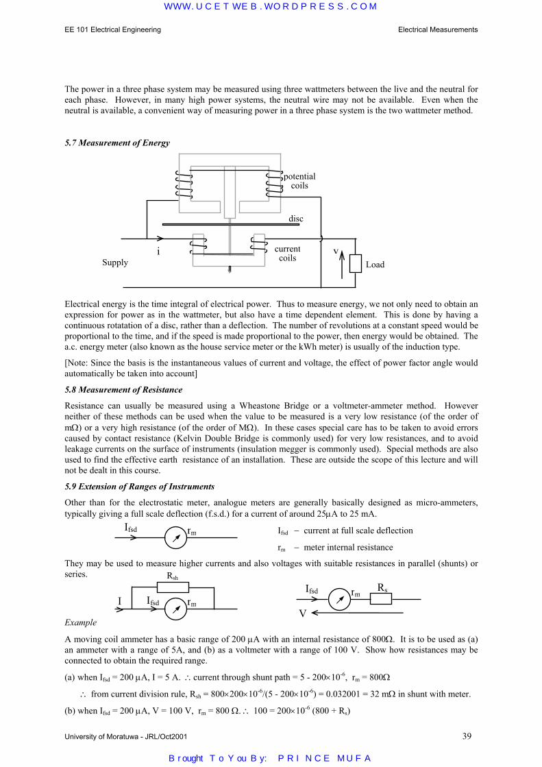
EE 101 Electrical Engineering Electrical Measurements
University of Moratuwa - JRL/Oct2001 39
The power in a three phase system may be measured using three wattmeters between the live and the neutral for each phase. However, in many high power systems, the neutral wire may not be available. Even when the neutral is available, a convenient way of measuring power in a three phase system is the two wattmeter method.
5.7 Measurement of Energy
Electrical energy is the time integral of electrical power. Thus to measure energy, we not only need to obtain an expression for power as in the wattmeter, but also have a time dependent element. This is done by having a continuous rotatation of a disc, rather than a deflection. The number of revolutions at a constant speed would be proportional to the time, and if the speed is made proportional to the power, then energy would be obtained. The a.c. energy meter (also known as the house service meter or the kWh meter) is usually of the induction type.
[Note: Since the basis is the instantaneous values of current and voltage, the effect of power factor angle would automatically be taken into account]
5.8 Measurement of Resistance
Resistance can usually be measured using a Wheastone Bridge or a voltmeter-ammeter method. However neither of these methods can be used when the value to be measured is a very low resistance (of the order of mΩ) or a very high resistance (of the order of MΩ). In these cases special care has to be taken to avoid errors caused by contact resistance (Kelvin Double Bridge is commonly used) for very low resistances, and to avoid leakage currents on the surface of instruments (insulation megger is commonly used). Special methods are also used to find the effective earth resistance of an installation. These are outside the scope of this lecture and will not be dealt in this course.
5.9 Extension of Ranges of Instruments
Other than for the electrostatic meter, analogue meters are generally basically designed as micro-ammeters, typically giving a full scale deflection (f.s.d.) for a current of around 25µA to 25 mA.
Ifsd − current at full scale deflection
rm − meter internal resistance
They may be used to measure higher currents and also voltages with suitable resistances in parallel (shunts) or series.
Example
A moving coil ammeter has a basic range of 200 µA with an internal resistance of 800Ω. It is to be used as (a) an ammeter with a range of 5A, and (b) as a voltmeter with a range of 100 V. Show how resistances may be connected to obtain the required range.
(a) when Ifsd = 200 µA, I = 5 A. ∴current through shunt path = 5 - 200×10-6, rm = 800Ω
∴ from current division rule, Rsh = 800×200×10-6/(5 - 200×10-6) = 0.032001 = 32 mΩ in shunt with meter.
(b) when Ifsd = 200 µA, V = 100 V, rm = 800 Ω. ∴ 100 = 200×10-6 (800 + Rs)
rm Ifsd
rm Ifsd
Rsh
I rm Ifsd Rs
V
Supply Load i
disc
potential coils
currentcoils
v
WWW.UCETWEB.WORDPRESS.COM
Brought To You By: PRINCE MUFA

EE 101 Electrical Engineering Electrical Measurements
University of Moratuwa - JRL/Oct2001 40
∴RS = 499200 = 499.2 kΩ in series with meter.
5.10 Instrument Transformers
The range of a meter can also be extended by making use of the transformer principle. If we wish to measure a larger or smaller voltage with a given range voltmeter, we could use a step down transformer or a step up transformer to achieve the purpose.
For example, to measure a high voltage of the order of 200 kV with a 100 V range voltmeter, we would use a potential transformer of turns ratio 2000:1 (or voltage ratio 200kV:100V) to reduce the voltage. [You are probably aware that the voltage ratio of a transformer is the same as the turns ratio]
Similarly larger or smaller currents may be measured using current transformers. For example, to measure a current of 200 A using a meter of range 5 A, we would use a current transformer of turns ratio 1:40 (or current ratio 200A:5A) to reduce the current.
Such potential transformers and current transformers are known as instrument transformers. They are specifically designed to have high accuracy in measuring voltages and currents respectively, but cannot handle much power. Like voltmeters, the primary of the potential transformer is connected in shunt with the quantity to be measured, while the primary of the current transformer is connected in series with the quantity to be measured. The secondary of a current transformer should never be left on open circuit in a live circuit to avoid it getting saturated.
5.11 Digital Meters
Analogue instruments display the quantity to be measured in terms of the deflection of a pointer. Digital instruments on the other hand indicate the value of the measured quantity (measurand) in the form of a decimal number. The digital meter works on the principle of sampling and quantization and their output may be fed into digital computers and the like for storage and future computations.
A digital voltmeter (DVM) measuring alternating voltages would typically have the following block diagram.
The analogue to digital converter (ADC) is the most critical component of the DVM. It determines the accuracy and the resolution of the DVM.
5.12 Symbols on dials of meters
The following symbols and abbreviations are used to denote the type of measuring element, kind of supply, and normal position of use of a given instrument.
Note: The hot-wire type of thermal instrument has not been described earlier in the notes. It works on the principle of a wire heating up due to the passage of current and causing an expansion. Details beyond this are beyond the scope of the lecture.
Attenuation and Range Selection
Amplification Rectification Analog to Digital Conversion Display
Input V
digital output
permanent magnet
moving coil moving iron moving coil
with Rectifierinduction type electrostatic hot-wire type
for d.c. use only for a.c. use only for a.c. and d.c. usevertical position for normal use
horizontal position for normal use
WWW.UCETWEB.WORDPRESS.COM
Brought To You By: PRINCE MUFA

6.0 Electrical Installations An electrical installation is a combination of electrical equipment installed to fulfill a specific purpose and having coordinated characteristics. In dealing with the electrical installation, it is necessary to ensure the safety of personnel as well as the protection of equipment from electrical faults.
The most common types of faults in domestic systems are (a) the short circuit faults (phase to neutral faults) - as a result of which large currents will flow and damage may occur to wires, insulators, switches, etc., due to over heating; and (b) insulation failure (fault between the phase conductor and non-current carrying metallic parts) of an electrical equipment - as a result of which high voltages may appear on the frames of equipment and may be dangerous to a person coming in contact with it.
Therefore, all electrical wiring systems and all electrical apparatus associated with wiring must be protected to:
(a) prevent damage by fire or shock (b) maintain continuity of the supply (c) disconnect faulty apparatus from the remainder of the system (d) prevent damage to wiring and equipment (e) minimize the system interruptions under fault conditions.
Protection must be provided against excess currents and earth leakage. Protective equipment must possess the following features:
(a) Certainty and reliability of operation under fault conditions and non-operation under normal conditions. (b) Discrimination (c) Rapidity of operation (d) Simplicity, low initial and maintenance cost (e) Easy adjustment and testing.
The most popular methods of protection are
(i) earthing or grounding of equipment (ii) use of fuses or circuit breakers (such as the Miniature Circuit Breaker – MCB) (iii) use of earth leakage and residual current circuit breakers.
6.1 Earthing or grounding of equipment refers to the connection of non-current carrying parts of electrical equipment to the earth to maintain earth potential. In domestic systems, the earthing circuit is usually earthed by connecting to metallic water pipes buried in ground. An effective earthing (grounding) system avoids having dangerous potentials on the equipment even during electrical faults and also ensures the proper operation of electrical protection equipment during fault conditions (this will be discussed under the operation of Earth Leakage and Residual Current Circuit Breakers).
Fuses: Fuses are the earliest means of protection against over-currents in circuits. Basically, the fuse consists of a short length of suitable material (often a thin wire). When the current flow is greater than the fusing current of the fuse, it will get hot and burn (melt), thus interrupting the fault current before damage could be caused. The size of the wire is designed to carry indefinitely the normal circuit current (rated current) and usually designed to fuse (melt/burn) at about 1.7 – 2 times the rated current carrying capacity. They have inverse time characteristics as shown in Figure 1. Accordingly, the operation of the fuse is faster when the fault current is larger.
In addition to operating for short circuits between the live and neutral, fuses are expected to operate under over-load conditions. Over-loading occurs when extra power is taken from the supply. The increased current due to over-loading will have an immediate effect on the cables; they will begin to heat up. If the over-loading is sustained the result could be an accelerated deterioration of the cable insulation and its eventual breakdown to cause an electrical fault. A heavy-sudden over-load for a very short period (e.g. such as in Motor starting) is not very serious since the over-load current flows for a short time and the rise in cable temperature is not very high.
6.2 Fuses
Terms commonly used with fuses
Fuse: a devise for opening a circuit by means of a conductor designed to melt when an excessive current flows along it.
Fuse element: part of a fuse, which is designed to melt and thus open a circuit
Fusing time (ms)
Rated current
current (A)
WWW.UCETWEB.WORDPRESS.COM
Brought To You By: PRINCE MUFA
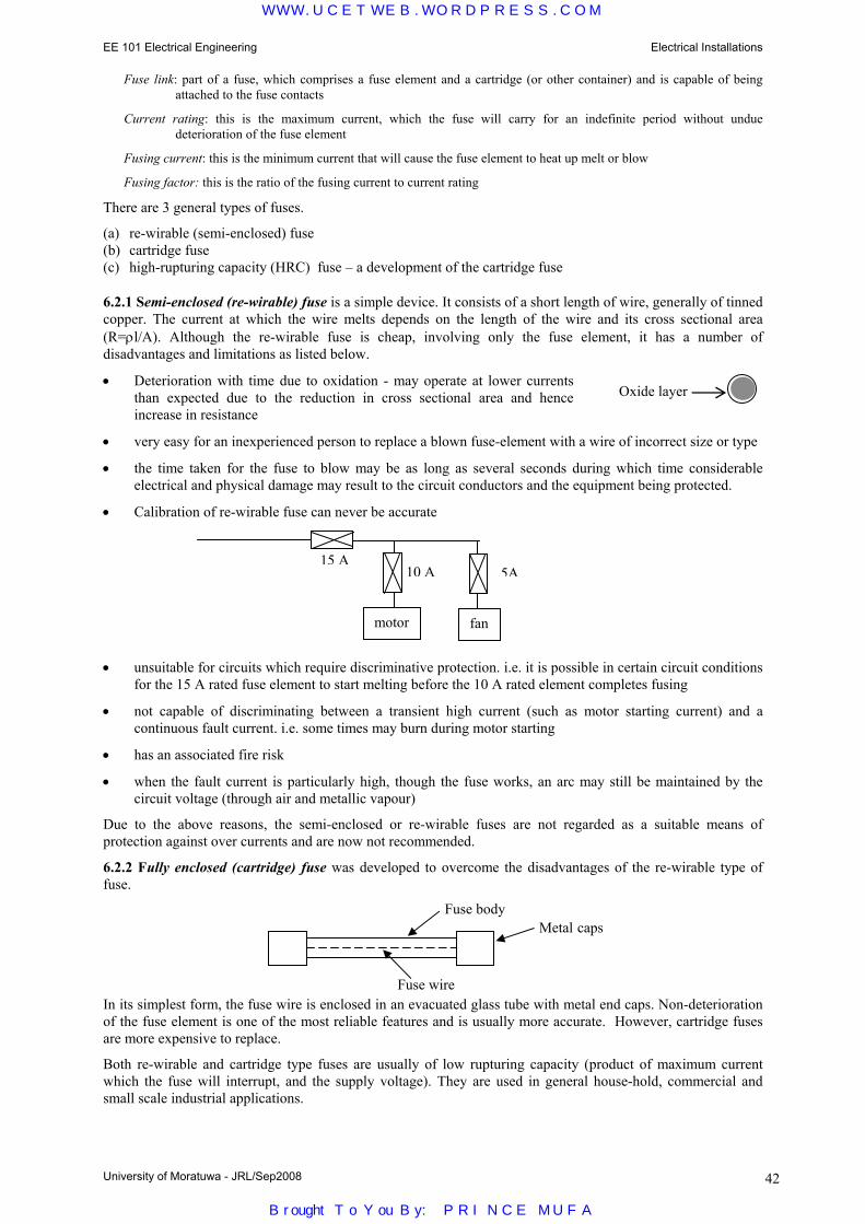
EE 101 Electrical Engineering Electrical Installations
University of Moratuwa - JRL/Sep2008 42
Fuse link: part of a fuse, which comprises a fuse element and a cartridge (or other container) and is capable of being attached to the fuse contacts
Current rating: this is the maximum current, which the fuse will carry for an indefinite period without undue deterioration of the fuse element
Fusing current: this is the minimum current that will cause the fuse element to heat up melt or blow
Fusing factor: this is the ratio of the fusing current to current rating
There are 3 general types of fuses.
(a) re-wirable (semi-enclosed) fuse (b) cartridge fuse (c) high-rupturing capacity (HRC) fuse – a development of the cartridge fuse
6.2.1 Semi-enclosed (re-wirable) fuse is a simple device. It consists of a short length of wire, generally of tinned copper. The current at which the wire melts depends on the length of the wire and its cross sectional area (R=ρl/A). Although the re-wirable fuse is cheap, involving only the fuse element, it has a number of disadvantages and limitations as listed below.
• Deterioration with time due to oxidation - may operate at lower currents than expected due to the reduction in cross sectional area and hence increase in resistance
• very easy for an inexperienced person to replace a blown fuse-element with a wire of incorrect size or type
• the time taken for the fuse to blow may be as long as several seconds during which time considerable electrical and physical damage may result to the circuit conductors and the equipment being protected.
• Calibration of re-wirable fuse can never be accurate
• unsuitable for circuits which require discriminative protection. i.e. it is possible in certain circuit conditions for the 15 A rated fuse element to start melting before the 10 A rated element completes fusing
• not capable of discriminating between a transient high current (such as motor starting current) and a continuous fault current. i.e. some times may burn during motor starting
• has an associated fire risk
• when the fault current is particularly high, though the fuse works, an arc may still be maintained by the circuit voltage (through air and metallic vapour)
Due to the above reasons, the semi-enclosed or re-wirable fuses are not regarded as a suitable means of protection against over currents and are now not recommended.
6.2.2 Fully enclosed (cartridge) fuse was developed to overcome the disadvantages of the re-wirable type of fuse.
In its simplest form, the fuse wire is enclosed in an evacuated glass tube with metal end caps. Non-deterioration of the fuse element is one of the most reliable features and is usually more accurate. However, cartridge fuses are more expensive to replace.
Both re-wirable and cartridge type fuses are usually of low rupturing capacity (product of maximum current which the fuse will interrupt, and the supply voltage). They are used in general house-hold, commercial and small scale industrial applications.
Oxide layer
motor fan
15 A10 A 5A
Fuse body
Fuse wire
Metal caps
WWW.UCETWEB.WORDPRESS.COM
Brought To You By: PRINCE MUFA

EE 101 Electrical Engineering Electrical Installations
University of Moratuwa - JRL/Sep2008 43
6.2.3 High rupturing capacity (HRC) fuses are used for high current applications.
The HRC fuse is usually a high-grade ceramic barrel containing the fuse element. The barrel is usually filled with sand, which helps to quench the resultant arc produced when the element melts. The barrel is able to withstand the shock-conditions which occur when a high fault current is interrupted. Normally, the fuse elements are in parts connected in the middle by bridges which have a very precise melting point of about 230 oC. These are very accurate. With a specific current, the temperature rises and the bridge melts producing a break in the circuit. The metal vapour diffuses with silica powder and the product is of high resistance. The HRC fuses are expensive to replace once blown.
6.3 Circuit breakers for over current protection
The circuit breaker is a device for making and breaking a circuit (under normal and abnormal conditions). A circuit breaker is selected for a particular duty taking the following into consideration (a) the normal current it will have to carry and (b) the amount of current which the supply system will feed into the circuit under a fault (which current the circuit breaker will have to interrupt without damage to itself). It is able to provide a more accurate degree of over current protection than that normally provided by either semi-enclosed or cartridge fuses.
The circuit breaker has a mechanism which, when it is in the closed position, holds the contacts together. The contacts are separated when the release mechanism of the circuit breaker is operated by hand or automatically. Miniature Circuit Breakers (mcb), which are commonly used in domestic installations, incorporate most of the features of the circuit breaker in a compact form and are being fitted in place of fuses in consumer units in the home or office. An MCB eliminates the cost of fuse replacement and may be used as a switch for isolating circuits. In the mcb, the automatic operation is by magnetic or thermal means. The reason for the two characteristics is to have proper operation during both short circuit and overload conditions. Magnetic mechanism
The magnetic mechanism uses a solenoid with an iron piece. It is used for short circuit (fault) protection, as high fault currents have to be isolated almost instantly. When the circuit current is above a certain level, the magnetic field strength increases to cause the iron piece to move in the direction of solenoid. This operates the tripping linkage and open the contacts. Even if the mcb is closed again, the contacts will not hold while the fault is still present.
Thermal mechanism
The thermal mechanism uses a heat sensitive bimetal element. When the element is heated to a pre-determined temperature, the resultant deflection trips the circuit breaker. The time taken to heat the element to this temperature depends on the magnitude of the current and provides the necessary time delay characteristics (tripping by this means is not so rapid as with magnetic tripping).
When a small sustained overload occurs, the thermal trip will come into operation after a few seconds or even minutes. However, when a heavier over load occurs, the magnetic trip coil operates quickly to disconnect the faulty circuit. This time delay characteristic is useful to avoid unwanted interruptions during the starting of motors and similar instances where the initial current may be high, but not an overload condition.
Advantages of mcb s over fuses are − Non destructive determination of tripping characteristics − Shorter tripping times under moderate over currents than with fuses − Immediate indication of faulty circuit − Reclosing can be effected at once after the fault has been cleared − No stock of fuses are required − Can be easily used as a circuit control switch when needed
Section of HRC fuse
WWW.UCETWEB.WORDPRESS.COM
Brought To You By: PRINCE MUFA

EE 101 Electrical Engineering Electrical Installations
University of Moratuwa - JRL/Sep2008 44
6.4 Circuit Breakers for earth leakage circuit protection:
These are used to detect electrical faults to earth in equipment and to clear the fault by tripping and may be classified into two types:
• Voltage operated protection − Earth Leakage Circuit Breaker (ELCB) • Current operated protection − Residual Current Circuit Breakers (RCCB) or Residual Current Device (RCD)
The earth leakage protection device is commonly known as Trip Switch by electricians.
Earth Leakage Circuit Breaker (ELCB): It is to be noted that for the proper operation of the ELCB, two earth terminals are required. These are the frame earth to which all non-conducting metallic parts of equipment are connected, and the ELCB reference earth. The ELCB will normally operate when the voltage across the coil, which corresponds to the voltage of the frame earth with respect to the reference earth, exceeds about 40 V. [Note: Up to about 50V has been traditionally considered as a safe voltage. However, it is now known that what is important is the current that may pass through the human body rather than the voltage, and that too is time dependent. Thus the RCCB is now preferred to the ELCB.
Residual Current Circuit Breaker (RCCB): The operation is based on a fault current, causing a difference between the line current and the neutral current (the difference need not actually flow to earth but back to the circuit through an unplanned path). This difference is used to energize the solenoid, which causes the switch to open. Under normal operating conditions, two identical windings, m1 and m2, will carry the main current. Since the currents are equal and opposite through the two windings, there is mmf balance and there will be no induced emf on the detector winding. Thus the operating coil will not be energized. However, in case of a fault the line and neutral currents will not equal and the trip coil will be energized due to the induced currents in the detector winding.
In both the ELCB and the RCCB, a test switch ‘T’ is provided to create an artificial fault for test purposes.
Advantages of RCCB: If the live wire is exposed (the insulation is open) and then some body touches it, he may get a shock if a current passes through him. In the case of voltage operated ELCB this earth current is not going through the tripping coiland will cause danger. But in the case of RCCB, the return path is going to loose part of the current, which passed through the human body, which in turn would cause a resultant flux within the ring energizing the tripping circuit.
6.5 Earthing or Grounding Earthing is carried out in an electrical installation for the purpose of, (a) limiting the potential (voltage) of current carrying conductors forming a part of the system − “neutral
earthing” (b) limiting the potential of non-current carrying metal work associated with equipment, apparatus and
appliances in the system − “equipment earthing”. The potential of an installation is measured with respect to the general mass of the earth or commonly called earth. Thus the potential is limited with respect to earth.
Neutral earthing: This is important because the performance of the system in terms of short circuits, stability, protection, etc., is greatly affected by the state of the neutral conductor. When the neutral is properly grounded, voltages of the phases are limited to near phase to ground voltage.
Equipment earthing: This refers to grounding of all metal work of equipment other than the parts which are normally current carrying. This is governed by various regulations such as the IEE regulations. The objective of this grounding is to ensure effective and rapid operation of the protective gear in the event of earth fault currents which might otherwise be undetected and cause fire and also protect against danger to life through shock due to installation metal work being maintained at a dangerous potential relative to earth.
V
WWW.UCETWEB.WORDPRESS.COM
Brought To You By: PRINCE MUFA

EE 101 Electrical Engineering Electrical Installations
University of Moratuwa - JRL/Sep2008 45
6.5.1 Types of earthing arrangement:
In the regulations for electrical installations, the types of earthing systems are identified as follows, depending on the relationship of the source (supply authority network) and of the exposed conductive parts of the installation, to earth.
These are
(1) TN - earthing of the installation is done to that supplied by the supply authority (2) TT - supply authority earth and the installation earth is independent (3) IT - supply authority has effectively an isolated neutral and the installation has an independent earth
In these, the first letter denotes the earthing arrangement at the supply authority side and the second letter denotes the relationship of the exposed conductive parts of the installation to earth.
With the First letter, T (short for terra or earth) refers to a direct connection of one or more points of the source to earth, and I (short for isolated) indicated that all live parts are isolated from earth or one point connected to earth through a high impedance.
With the Second letter, T denotes a direct electrical connection of the exposed conductive parts of the consumers installation to earth, independently of the earthing of any point of the supply authority side, while N denotes a direct electrical connection of the exposed conductive parts to the earthed point of the supply authority side, which for ac is usually the neutral point.
[There are further sub-divisions of the TN system, but are considered to be beyond the contents of this course. Even the details of the earthing systems other than the one used in Sri Lanka will not be dealt with in this course]
TT System
The TT System of earthing is the one used in Sri Lanka. In this system, the supply is earthed at the source end, and all exposed-conductive parts of the installation are connected to an electrically independent earth electrode at the consumer end.
The normal earthing practice is to provide a circuit protective conductor throughout every installation. A circuit protective conductor connects exposed conductive parts of equipment to the main earthing terminal. As mentioned earlier, the most common method employed for earthing, at the domestic installations in Sri Lanka, is to use an earth electrode (commonly a galvanized iron pipe). The resistance of this electrode to earth also depends on the condition of soil and may have values in excess of 100 Ω. Thus in the TT system of earthing, it is now essential to use an RCCB for protection.
source of energy
consumer installations
installation earth electrodes
equipment in installation
exposed conductive parts
source earth
L1
L2
L3
N
WWW.UCETWEB.WORDPRESS.COM
Brought To You By: PRINCE MUFA

EE 101 Electrical Engineering Electrical Installations
University of Moratuwa - JRL/Sep2008 46
6.6 Basic Domestic Installations:
Most of the domestic installations in Sri Lanka are of single phase (2 wire) type and supplied at 230 V line to neutral. Basic arrangement of the connections from the supply authority’s distribution pole is shown. This shows the installation diagram from the service cable of the supply authority, which is usually supplied overhead from the distribution pole. This comes to the service fuse box (or cut out as commonly known) and then to the energy meter. Up to the energy meter belongs to the supply authority. The consumer’s installation proper starts from the Main switch, which in Sri Lanka is likely not to exceed 30A for a single phase supply. This will be followed by usually one (or more) RCCBs (other than some older installations which have an ELCBs, and some even older installations which have no earth leakage protection). Each RCCB would be followed by a Consumer Unit (with different rated MCBs) or in older installations a Distribution Board (with Fuses). The final circuits are taken from the consumer unit (or distribution unit) Loop-in Method
Figure shows the use of loop-in method for wiring a final circuit for lighting. The loop in method enables all joints and terminations in a single final circuit to be made at ceiling roses, switches or other accessories. This makes all joints accessible for the purpose of alterations and for testing. Each final circuit has both its live conductor as well as the neutral conductor terminating at the consumer unit. The wires are usually laid in PVC conduits. Lamp circuits do not normally need an earth wire unless there is a metallic fitting which needs to be earthed for safety. Two way switches
A two-way switch is used when it is necessary to operate a lamp from two positions, such as at the top and bottom of a staircase and at the ends of a long corridor. The connection and operation are shown in the figure.
Final circuits for socket outlets: Socket outlets (commonly called plug points by electricians) are wired in two ways. These are the ring circuit connection and the radial connection.
(a) Ring circuits Each circuit commences from consumer unit (or distribution board) through an MCB (or fuse) of specific rating usually 30 A, loops into each socket outlet and returns to the same MCB (or fuse) in the consumer unit (distribution board). Looping must be done for the live conductor, neutral conductor and the protective conductor in separate rings. The ring method of connection is done only for the 13 A socket outlets, as the individual 13A plugs are separately having fuses (fuses may be usually rated at 13 A or 3 A depending on the type of load).
L N
N1
N2
N3
L1
L2
L3
FinalCircuits
RCCB“Trip Switch”
Consumer Unitearth
Consumer’sMain Switch
Fuse
MCBs
Energy meter
Servicefuse box
Fuse
Service cables
L
N
single gangswitch
3-gangswitch
lamps
lamp
ceilingrose
L
N
lamptwo-wayswitch
two-wayswitch
L
N
lamptwo-wayswitch
two-wayswitch
circuit on circuit off
E
WWW.UCETWEB.WORDPRESS.COM
Brought To You By: PRINCE MUFA

EE 101 Electrical Engineering Electrical Installations
University of Moratuwa - JRL/Sep2008 47
N L
E
socket outlet
joint box
30A MCB
spur box
permanent connected appliance
A typical ring circuit connection is shown in the figure. A ring circuit may have an unlimited number of socket outlets provided that the floor area served by the ring does not exceed 100 m2 and that the maximum demand of the circuit does not exceed the MCB (or fuse) rating. A kitchen should usually have a separate ring circuit. (b) Radial circuits Each circuit commences from the consumer unit/distribution board through an MCB/fuse of specific rating (e.g. 20A), loop into each socket outlet but ends at a socket outlet (does not return to the original fuse/mcb).
Figure shows a typical radial circuit connection.
6.7 Electric Shock If an electric current passes through the human body, the effects could be an electric shock or even death. The degree of danger of electric shock depends on the value of the body current and the time for which the current flows. A low current for a long time can easily prove just as dangerous as a high current for a relatively brief time. One of the objects of earthing is to reduce the amount of current available for passage through the human body in the event of the occurrence of an earth leakage current in an installation. The figure shows the time/current zones of effects of 50 Hz current on the human body.
10
100
1000
10000
0.1 1 10 100 1000 10000
body current (mA)
time
(ms)
1 2 4
c
3
a b
NL
E socketoutlet
joint box20A MCB
WWW.UCETWEB.WORDPRESS.COM
Brought To You By: PRINCE MUFA

EE 101 Electrical Engineering Electrical Installations
University of Moratuwa - JRL/Sep2008 48
Zone 1 - No sensation Zone 2 - Perceptibility of current, but no harmful effect (10 mA is the threshold of let-go) Zone 3 - Mascular contractions and difficulty in breathing. Usually no danger of ventricular fibrillation
(0.5% probability) Zone 4 - Probability of ventricular fibrillation increases a - up to 5% , b - up to 50% , c - greater than 50% Ventricular fibrillation of the heart is the prevention of the heart to act as an effective pump, and thus causing a stoppage of blood circulation to all parts of the body, resulting in death in a very short time. It can be seen that a current of 30 mA never goes into zone 4, and is thus typically used in residual current devices used for safety of persons.
6.8 IEE Wiring Regulations It is obvious, even to a lay person, that electricity can, if uncontrolled, present a serious threat of injury to persons or livestock, or damage to property by fire. Thus, rules and regulations have been framed to govern the practice to ensure that all electrical installations provide adequate degree of safety from fire and shock risks, to those who operate the installations and their associated apparatus, equipment and machines. Every person who is involved in design and construction of electrical installation must be familiar with the principal set of regulations issued by the Institution of Electrical Engineers for Electrical Installations, commonly known as the IEE Wiring Regulations. He is also required to be familiar with the main requirements of other regulations, some of which are statutory, such as the Electricity Act of Sri Lanka and the regulations framed under it. The IEE Wiring Regulations have evolved over the past century and is a set of recommendations for safe selection and erection of wiring systems. In Sri Lanka it is also a legal requirement that electrical installations satisfy the IEE Wiring Regulations. At present, the 16th Edition (1992) of IEE Wiring Regulations is used. Following are some important information available in these regulations: • The Regulations are designed to protect persons, property and livestock from electric shock, fire, burns
and injury from mechanical movement of electrically actuated equipment. • Prevention of electric shock is carried out by Insulation of live parts, formation of barriers or enclosures,
keeping obstacles and making the place out of reach, etc. • Fundamental requirements for safety require the use good workmanship, approved materials and
equipment to ensure that the correct type, size and current-carrying capacity of cables is chosen. The regulations also ensure that the equipment is suitable for the maximum power demanded of it and make sure that the conductors are insulated, and sheathed or protected if necessary, or are placed in a position to prevent danger. Joints and connections should be properly constructed to be mechanically and electrically sound. Over-current protection should always be provided for every circuit in an installation (the protection for the whole installation is usually provided by the supply authority). They ensure that protective devices are suitably chosen for their location and the duty they have to perform. Where there is a chance of metalwork becoming live owing to a fault, it should be earthed, and the circuit concerned should be protected by an over-current device or a residual current device (RCD). A fuse, a switch or a circuit breaker should not be placed a in an earthed neutral conductor. It requires that all single-pole switches are wired in the phase conductor only. A readily accessible and effective means of isolation must be provided, so that all voltage may be cut off from an installation or any of its circuits. All motors must have a readily accessible means of disconnection. They ensure that any item of equipment which may normally need operating or attending to by persons is accessible and easily operated. Any equipment required to be installed in a situation exposed to weather or corrosion, or in explosive or volatile environments, should be of correct type for such adverse conditions. Before adding to or altering an installation, it should be ensured that such work will not damage/weaken any part of the existing installation. After completion of an installation or an alteration to an installation, the work must be inspected and tested to ensure, as far as reasonably practicable, that the fundamental requirements for safety have been met.
• Among the requirements for Inspection includes checking the connection of conductors, identification of conductors, checking routing of cables, checking proper selection of conductors, checking connection of single-pole devices, checking connection of equipment, checking for presence of fire barriers, methods of protection against electric shock, prevention of detrimental influences, presence of appropriate devices for isolating and switching, presence of under-voltage protective devices, choice of setting of protective devices, labelling of protective devices, switches and terminals, selection of equipment appropriate to external influences, access to switchgear and equipment, presence of warning signs and danger notices, presence of diagrams, instructions and similar information and erection methods.
• Testing includes continuity of live, neutral and protective conductors, the resistance of earth electrodes, insulation resistance of all live conductors to earth, insulation resistance between live conductors, polarity to ensure all switches are connected in phase conductors and not neutral; phase earth loop impedance tests, operation of residual current devices.
WWW.UCETWEB.WORDPRESS.COM
Brought To You By: PRINCE MUFA

EE 101 Electrical Engineering Electric Motors
University of Moratuwa - JRL/Sep2008 1
Electric Drives Electromechanical energy conversion:
Electrical Energy is obtained by the conversion of other forms of energy, based on the principle of conservation of energy. The main advantage of this conversion is that energy in electrical form can be transmitted, utilised and controlled more easily, reliably and efficiently than in any other form.
An electro-mechanical energy conversion device is one which converts electrical energy into mechanical energy (electric motors) or mechanical energy into electrical energy (electric generators). The electro-mechanical energy conversion process is a reversible process. However, devices are designed and constructed to suit one particular process rather than the other. In an energy conversion device, out of the total input energy, some energy is converted into the required form, some energy is stored and rest is dissipated.
For practical application we need to convert electrical energy into the required useful form, such as mechanical energy, heat, light, sound and electromagnetic waves. One of the major applications is electric drives which uses motors.
Figure 1 - Power flow in an electric motor The energy balance for a motor (shown in block diagrammatic form in figure 1) can be written as
Total electrical energy input = mechanical energy output + total energy stored + total energy dissipated
In a motor, energy is stored in the magnetic field and mechanical system. The energy dissipated is in the electric circuit as ohmic losses, in the magnetic circuit as core losses (hysteresis and eddy-current losses), and in the mechanical system as friction and windage losses. [ω is the angular velocity of rotation]. An electric motor provides the driving torque necessary to keep machinery running at the required speed, with provision being made for speed control and reversal of rotation. The electrical motor is required to start, accelerate, drive and decelerate its load, within certain limitations. There are three main types of motors - Direct Current Motor, Induction Motor and Synchronous Motor
Direct Current (dc) Motors
Direct current (dc) motors operate on a magnetic field produced by the field winding in the stator (stationary part of the motor) interacting with the field produced by the armature winding in the rotor (rotating part). The basic constructional features of a typical two-pole dc motor are shown in the figure 2 and the circuit model in figure 3.
Figure 2 - two-pole dc motor Figure 3 - Circuit model of a dc motor
The dc motor needs slip rings or split rings (commutator) on the rotor shaft and a set of brushes positioned over them to supply the armature winding. [symbol for the armature basically shows the rotor and a pair of brushes]
(a) separately excited (b) shunt excited (c) series excited (d) compound excited
Figure 4 - categorisation of dc motors
shaft
Electric Motor Pstored, elect Pstored, mech
Mechanical
Load
Ploss,elect
Pinput
Ploss,mech
Poutput
ω
dc supply dc supply dc supply dc supply dc supply
−Vf field supply
armature supply
+
−V
+Rf
ra Ea If +
−ω τPmech V = Ea + ra Ia
Ia
WWW.UCETWEB.WORDPRESS.COM
Brought To You By: PRINCE MUFA

EE 101 Electrical Engineering Electric Motors
University of Moratuwa - JRL/Sep2008 2
The dc motors can be categorised into four basic types dependent on the method of connection of the field winding (figure 4). These are the (a) separately excited field, (b) shunt connected field, (c) series connected field, and (d) compound connected field.
In the separately excited type, the field winding is connected to a separate or external dc source. In the shunt excited type, the field winding is connected in parallel with the armature winding so that the same dc voltage source is used. In the series excited type, the field winding is connected in series with the armature winding, again making use of the same dc voltage source. Compound excitation involves both the series and shunt excited windings.
In the case of very small motors, the field may be created by a permanent magnet rather than having a field winding. These are known as permanent magnet dc motors.
Speed-torque characteristics of dc motors
The shunt, series and compound motors exhibit distinctive speed-torque characteristics, which are best suited for specific tasks. Thus a study of motor characteristics is essential for one to decide on a specific application using these motors. Figure 5 shows the speed-torque characteristics of dc motors. In addition, other characteristics such as torque-current should be considered when selecting motors.
(a) shunt motor (b) series motor (c) compound motor
Figure 5 - Speed-torque characteristics of dc motors
DC motor applications
Although ac supplies are now universal, there are many applications, where the dc motor finds its place.
The dc shunt motor has a fairly constant speed against a varying load or torque. Thus, applications include situations where a constant speed is required such as in lathes, conveyors, fans and machine-tool drives. Since the dc series motor is able to create large torques at low speeds (high starting torque), it can be used to accelerate very heavy loads from standstill. Thus, dc series motors are used for driving cranes, electric locomotives, group drive shafts (where the motor is used as a drive for a whole assembly line), steel-rolling mills and so on. Compound motors combine the characteristics of both shunt and series wound motors. The series winding gives good starting torque and shunt winding ensures a comparatively constant speed. The actual characteristics of the compound motor can be varied by varying the ratio of shunt to series field turns. They are used in applications such as planers, shears, guillotines, printing machines and power presses that need peak loads at certain instances (normally used with fly wheels to even out the load). Separately excited motors are used in applications where an independent armature control and field control is required. Examples of their use are in steel and aluminium rolling mills (high power) and control motors (low power).
In addition, permanent magnet motors are used for low power applications. These are specially used in automobiles as starter motors, wiper motors, blowers in heaters and air-conditioners, in raising and lowering windows. They are also used in such other applications as toys, electric tooth-brushes.
Stepper Motors
In certain applications, it is necessary to spin quickly and move to a precise point, such as in computer disk drives. This can be accomplished by using a stepper motor. Stepper motors can be viewed as electric motors without commutators. Typically, all windings in the motor are part of the stator, and the rotor is either a permanent magnet or, in the case of variable reluctance motors, a toothed block of some magnetically soft material. The motors and controllers are designed so that the motor may be held in any fixed position as well as being rotated one way or the other. Most stepper motors can be stepped at audio frequencies, allowing them to spin quite quickly, and with an appropriate controller, they may be started and stopped precisely.
AC Motors
With almost the universal adoption of the ac system of distribution of electric energy for light and power, the field of application of ac motors has widened considerably. There are a number of different types of ac motors, each of which offers certain specific advantages.
ω
τ
ω
τ
ω
τ
differential
cumulative
WWW.UCETWEB.WORDPRESS.COM
Brought To You By: PRINCE MUFA
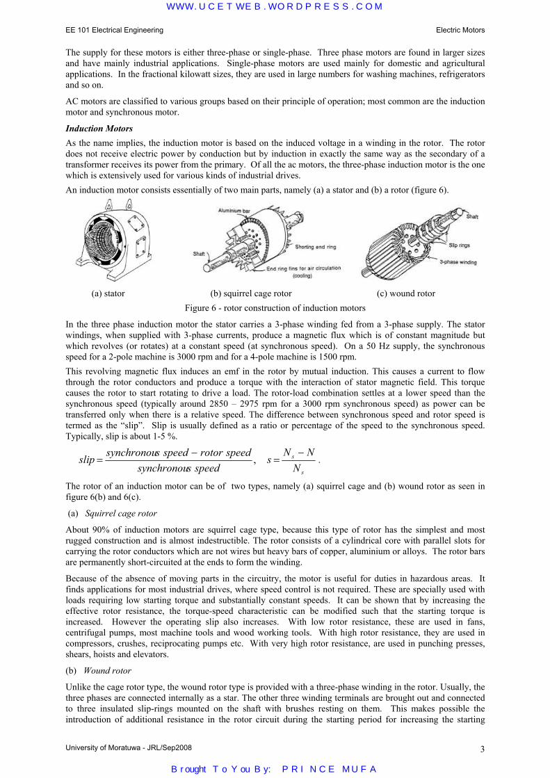
EE 101 Electrical Engineering Electric Motors
University of Moratuwa - JRL/Sep2008 3
The supply for these motors is either three-phase or single-phase. Three phase motors are found in larger sizes and have mainly industrial applications. Single-phase motors are used mainly for domestic and agricultural applications. In the fractional kilowatt sizes, they are used in large numbers for washing machines, refrigerators and so on.
AC motors are classified to various groups based on their principle of operation; most common are the induction motor and synchronous motor.
Induction Motors As the name implies, the induction motor is based on the induced voltage in a winding in the rotor. The rotor does not receive electric power by conduction but by induction in exactly the same way as the secondary of a transformer receives its power from the primary. Of all the ac motors, the three-phase induction motor is the one which is extensively used for various kinds of industrial drives. An induction motor consists essentially of two main parts, namely (a) a stator and (b) a rotor (figure 6).
(a) stator (b) squirrel cage rotor (c) wound rotor
Figure 6 - rotor construction of induction motors
In the three phase induction motor the stator carries a 3-phase winding fed from a 3-phase supply. The stator windings, when supplied with 3-phase currents, produce a magnetic flux which is of constant magnitude but which revolves (or rotates) at a constant speed (at synchronous speed). On a 50 Hz supply, the synchronous speed for a 2-pole machine is 3000 rpm and for a 4-pole machine is 1500 rpm. This revolving magnetic flux induces an emf in the rotor by mutual induction. This causes a current to flow through the rotor conductors and produce a torque with the interaction of stator magnetic field. This torque causes the rotor to start rotating to drive a load. The rotor-load combination settles at a lower speed than the synchronous speed (typically around 2850 – 2975 rpm for a 3000 rpm synchronous speed) as power can be transferred only when there is a relative speed. The difference between synchronous speed and rotor speed is termed as the “slip”. Slip is usually defined as a ratio or percentage of the speed to the synchronous speed. Typically, slip is about 1-5 %.
s
s
NNN
sspeedssynchronou
speedrotorspeedssynchronouslip−
=−
= , .
The rotor of an induction motor can be of two types, namely (a) squirrel cage and (b) wound rotor as seen in figure 6(b) and 6(c).
(a) Squirrel cage rotor
About 90% of induction motors are squirrel cage type, because this type of rotor has the simplest and most rugged construction and is almost indestructible. The rotor consists of a cylindrical core with parallel slots for carrying the rotor conductors which are not wires but heavy bars of copper, aluminium or alloys. The rotor bars are permanently short-circuited at the ends to form the winding.
Because of the absence of moving parts in the circuitry, the motor is useful for duties in hazardous areas. It finds applications for most industrial drives, where speed control is not required. These are specially used with loads requiring low starting torque and substantially constant speeds. It can be shown that by increasing the effective rotor resistance, the torque-speed characteristic can be modified such that the starting torque is increased. However the operating slip also increases. With low rotor resistance, these are used in fans, centrifugal pumps, most machine tools and wood working tools. With high rotor resistance, they are used in compressors, crushes, reciprocating pumps etc. With very high rotor resistance, are used in punching presses, shears, hoists and elevators.
(b) Wound rotor
Unlike the cage rotor type, the wound rotor type is provided with a three-phase winding in the rotor. Usually, the three phases are connected internally as a star. The other three winding terminals are brought out and connected to three insulated slip-rings mounted on the shaft with brushes resting on them. This makes possible the introduction of additional resistance in the rotor circuit during the starting period for increasing the starting
WWW.UCETWEB.WORDPRESS.COM
Brought To You By: PRINCE MUFA

EE 101 Electrical Engineering Electric Motors
University of Moratuwa - JRL/Sep2008 4
torque of the motor and for changing its speed-torque/current characteristics. When running under normal conditions, the slip-rings are automatically short-circuited and the brushes lifted from the slip-rings. Hence, it is seen that under normal running conditions, the wound rotor is short-circuited on itself just like the squirrel cage rotor. Applications of the wound rotor type include high-inertia drives requiring variable speed, fly wheel machine drives, air-compressors, ram pumps, crushing mills, cranes, hoists, winches and lifts.
Typical Torque-speed characteristics of an induction motor are shown in figure 7. The effect of increasing the rotor resistance on the characteristic is also shown.
Figure 7 - Torque-speed characteristics of an induction motor
Synchronous Motors
Synchronous motors operate on the same fundamental principles of electromagnetic induction as dc motors. They usually consists of a 3-phase stator winding and a rotor winding which carries a dc current (figure 8). When the 3-phase stator winding is fed by a 3-phase supply, a magnetic flux of constant magnitude but rotating at synchronous speed, is produced (as in 3-phase induction motors). This field interacts with the field produced by the dc field winding on the rotor and produces a torque which can be used to rotate a load. It runs at a constant speed (synchronous speed). However, the synchronous motor is not self-starting and hence needs additional means for starting.
Although the induction motor is cheaper for small power applications, the synchronous motor is preferred for applications above 50 kW. Typical applications include Banbury mixers (used to mix raw ingredients for rubber production), cement grinding mills, centrifugal compressors, mine ventilating fans, pumps, reciprocating compressor drives, electric ship propulsion drives, large low head pumps, rolling mills, ball mills, pulp grinders, etc. They are also used for power factor correction and voltage regulation.
Single-Phase Motors
Single phase motors are designed to operate from a single-phase supply and are manufactured in a large number of types to perform a wide variety of useful services in homes, offices, factories, workshops, vehicles, air crafts, power tools, etc.
Single-phase motors are usually classified based on their operating principle and method of starting, such as
(1) Induction motors (split-phase, capacitor, shaded-pole etc.) (2) Repulsion motors (some times called inductive series motors) (3) AC series motors (4) Synchronous motors. The single-phase induction motor is similar to a three-phase induction motor except that its stator is provided with a single phase winding and a special mechanism employed for starting purposes (It does not develop a rotating field but a pulsating field). It has a distributed stator winding and a squirrel cage rotor. Special mechanisms are employed for starting and there are different motor types based on starting method such as split-phase (fans, blowers, centrifugal pumps, washing machines, small machine tools, duplicating machines, domestic refrigerators), capacitor start (small power drives) and shaded-pole (small fans, toys, instruments, hair dryers, ventilators, circulators, electric clocks). Repulsion type motor applications include machine tools, commercial refrigerators, compressors, pumps, hoists, floor-polishing and grinding devices, garage air-pumps, petrol pumps, mixing machines, lifts and hoists. The ac series motor is a modified ordinary dc series motor that can be connected to an ac supply. A similar one is the universal motor, which is a small version of ac series motor. This can work with both ac and dc and used in applications such as vacuum cleaners, food mixers, portable drills and domestic sewing machines. Single-phase synchronous motors are typically used in signaling devices, recording instruments and in many kinds of timers and house hold electric clocks.
Figure 8 - Synchronous Motor
WWW.UCETWEB.WORDPRESS.COM
Brought To You By: PRINCE MUFA