electrical engineering safety · a device to detect the lifting of the winder brakes. a device to...
TRANSCRIPT

T E C H N I C A L
EES008-2
Produced by Mine Safety Operations Branch
Industry and Investment NSW
March 2011
Definitions and winder types
Design of powered winding Systems
Electrical Engineering Safety
R E F E R E N C E
Public comment period
Please note that this technical reference is published in draft form for the purpose of obtaining public comment.
Your feedback is welcomed and will assist with reviewing and improving the document. A feedback form is provided in the appendices for your convenience.
The closing date for public comment is Friday 20 May 2011.
EES008-2 Design of powered winding systems-definitions and winder types March 2011
Page 2 of 52
various workers compensation and occupational health and safety legislation that Industry & Investment NSW administers. To ensure you comply with your legal obligations you must refer to the appropriate legislation.
In the event of inconsistency with a provision of any relevant Act or Regulation the provision prevails over the guideline.
D I S C L A I M E R
The compilation of information contained in this document relies upon material and data derived from a number of third party sources and is intended as a guide only in devising risk and safety management systems for the working of mines and is not designed to replace or be used instead of an appropriately designed safety management plan for each individual mine. Users should rely on their own advice, skills and experience in applying risk and safety management systems in individual workplaces.
Use of this document does not relieve the user (or a person on whose behalf it is used) of any obligation or duty that might arise under any legislation (including the Occupational Health and Safety Act 2000, any other act containing requirements relating to mine safety and any regulations and rules under those acts) covering the activities to which this document has been or is to be applied.
The information in this document is provided voluntarily and for information purposes only. The New South Wales Government does not guarantee that the information is complete, current or correct and accepts no responsibility for unsuitable or inaccurate material that may be encountered.
Unless otherwise stated, the authorised version of all reports, guides, data and other information should be sourced from official printed versions of the agency directly. Neither Industry & Investment NSW, the New South Wales Government, nor any employee or agent of the Department, nor any author of or contributor to this document produced by the Department, shall be responsible or liable for any loss, damage, personal injury or death howsoever caused. A reference in this document to "the Department" or "Industry and Investment NSW" or "I&I NSW" is taken to be a reference to the Department of Industry and Investment.
Users should always verify historical material by making and relying upon their own separate enquiries prior to making any important decisions or taking any action on the basis of this information.
This publication contains information regarding occupational health, safety, injury management or workers compensation. It includes some of your obligations under the
This publication may refer to NSW legislation that has been amended or repealed. When reading this publication you should always refer to the latest laws. Information on the latest laws can be checked at: www.legislation.nsw.gov.au Alternatively, phone (02) 4931 6666.
EES008-2 Design of powered winding systems-definitions and winder types March 2011
Page 3 of 52

must be at an engineering level, so electrical engineers within the management structure of coal or mining operations will be responsible for development, periodic review and day to day implementation of the Electrical Engineering Safety aspects of a powered winding system.
This document is one of a series dealing with powered winding systems. These documents are consistent with the above philosophy of operation and are a key element in realising the vision and points 4 and 5 for electrical engineering safety listed above.
Foreword
Industry and Investment NSW (I&I NSW) has a vision for electrical engineering safety, which is:
“A mining and extractive industry that has eliminated death and injuries from electrically powered and electrically controlled equipment.”
Electrical engineering safety encompasses: • Prevention of electric shock and burns, (electrocution, death or injury as a result
of a shock, radiation burns, flash burns, burning particles and plasma) • Prevention of electrical arcing and surface temperatures that have sufficient
energy to ignite gas and/or dust • Prevention of fires caused by the malfunction of electrical equipment • Prevention of injury and death from unintended operation, failure to stop or
failure to operate, of electrically powered and electrically controlled equipment • Use of electrical technology to provide safe-guards and monitoring for non
electrical hazards and electrical hazards with a safety integrity level appropriate for the risk.
Supporting this vision is a philosophy of operation outlined in the Strategic and Operational Plan for Electrical and Engineering Safety in NSW Mines, which can be viewed at www.dpi.nsw.gov.au. The philosophy of operation embraces a System Safety Approach, applying the Hierarchy of Risk Controls and the Risk Reduction Precedence, and fostering a Positive Safety Culture.
Satisfactory electrical engineering safety has to be achieved in the context of the mining industry’s increasing electricity consumption and its use of electrical technology, with resulting increases in size (power rating) and complexity. With this comes a changing risk profile. To adequately manage the safety risks posed by electrical equipment and technology the hazards, risks and risk controls need to be thoroughly understood. This understanding
The documents in the series are: EES008.1 Design of Powered Winding Systems - Electrical Engineering Safety – General Requirements & Registration EES008.2 Design of Powered Winding Systems - Electrical Engineering Safety – Definitions and types of winders EES008.3 Design of Powered Winding Systems - Electrical Engineering Safety – a prescriptive approach EES008.4 Design of Powered Winding Systems - Electrical Engineering Safety – a Functional Safety approach EES008.5 Life-Cycle Management of Powered Winding Systems - Electrical Engineering Safety Requirements
EES008-2 Design of powered winding systems-definitions and winder types March 2011
Page 4 of 52

Current legislation is consistent with this philosophy. In particular Clauses 107 and 113 of the Occupational Health and Safety Regulation 2001 recognise the high risk nature of mine winders, so legislation requires that the Director General design register and item register powered winding systems.
The purpose of this document is to facilitate, within an electrical engineering safety context, the design registration of powered winding systems and to assist coal and mine operators to maintain powered winding systems in a safe state.
Use of this document will:
• Enhance the management of safety risks associated with powered winding systems through good and safe electrical engineering practice
• Contribute significantly toward the prevention of unintended operation of mine winders and preventing any unintended operation from injuring personnel.
Use this technical reference to assess your Powered Winding Systems.
Use this technical reference as an aid to the design of Powered Winding Systems.
This technical reference will be used by Mine Safety Operations to assess powered winding systems for design registration purposes and routine assessment activities.
John Francis Waudby
Senior Inspector of Electrical Engineering – Special Projects
EES008-2 Design of powered winding systems-definitions and winder types March 2011
Page 5 of 52

Table of Contents
Foreword............................................................................................................................... 4
Table of Contents.................................................................................................................. 6
1. Establishment ................................................................................................................... 7
1.1 Title ............................................................................................................................. 7
1.2 Purpose....................................................................................................................... 7
1.3 Scope .......................................................................................................................... 7
1.4 Authority ...................................................................................................................... 7
1.5 Definitions.................................................................................................................... 7
1.6 Applicable legislation ................................................................................................... 8
1.7 Referenced Gazette Notices........................................................................................ 8
1.8 Referenced Standards and Guidelines ........................................................................ 8
1.9 Acronyms .................................................................................................................... 8
2. Definitions ....................................................................................................................... 10
1.10 Who is affected by this Technical Reference? ........................................................... 8
3. Winder characteristics..................................................................................................... 21
3.1 Winder types ............................................................................................................. 21
3.2 Winder Drive Systems ............................................................................................... 48
3.3 Winder Brake Types .................................................................................................. 48
3.4 Winder Brake Operating Mediums............................................................................. 48
4. Appendices ..................................................................................................................... 51
Feedback Sheet ................................................................. Error! Bookmark not defined.
I&I NSW Contact details ..................................................... Error! Bookmark not defined.
EES008-2 Design of powered winding systems-definitions and winder types March 2011
Page 6 of 52
1 . 4 Au t h o r i t y
Investment NSW.
1. Establ ishment�
1 . 1 T i t l e
This is the Mining Industry Technical reference – Electrical Technical Reference for Design of Powered Winding Systems Electrical Engineering Safety – definition and winder types.
1 . 2 P ur p os e
This document is intended to assist designers and manufactures of powered winding systems, including shaft sinking winders, by indicating parameters which will be considered in the assessment for design registration. It will also aid coal and mining operators to obtain item registration. It also provides specific information on the content of any submission for design registration. Full details of how to obtain design registration is given in Guidance Note GNC-005 NSW DPI Guidance Note – Registration of Plant Designs.
Registration does not limit the responsibility of the designer, Note manufacturer and operator to ensure that the powered winding system is
safe to operate.
This technical reference describes acceptable arrangements that can be tailored to suit the particular needs of an operation. It identifies some control measures relevant to electrical circuitry. It is intended to protect the safety of workers, others in the workplace and property.
1 . 3 Sc o p e
This technical reference extends to all underground coal and mining operations in NSW that use a powered winding system. This technical reference is intended to provide guidance for any person designing, implementing, managing or reviewing a powered winding system installation.
This is an electrical engineering safety technical reference and is recommended by the Mine Safety Operations branch of Industry and
1 . 5 D e f i n i t i o ns
See Chapter 2.
EES008-2 Design of powered winding systems-definitions and winder types March 2011
Page 7 of 52

Safety – General requirements and registration
Safety – a prescriptive approach
1 . 6 Ap p l i ca b l e l e g i s l a t i o n
Occupational Health and Safety Act 2000
Occupational Health and Safety Regulation 2001
Coal Mine Health and Safety Act 2002
Coal Mine Health and Safety Regulation 2006
Mine Health and Safety Act 2004
Mine Health and Safety Regulation 2007
1 . 7 R e f e r e n c ed G az e t te N o t i c e s
Gazette Notice for Powered Winding Systems
1 . 8 R e f e r e n c ed S t a nd ar d s an d G u i d e l i n es AS 61508 Series - Functional safety of electrical/electronic/programmable electronic safety-related systems
AS 62061 Safety of machinery - Functional safety of safety-related electrical, electronic and programmable electronic control systems
EES008.1 Design of Powered Winding Systems - Electrical Engineering
EES008.3 Design of Powered Winding Systems - Electrical Engineering
EES008.4 Design of Powered Winding Systems - Electrical Engineering Safety – a Functional Safety approach
EES008.5 Life-Cycle Management of Powered Winding Systems - Electrical Engineering Safety Requirements
Guidance Note GNC-005 NSW DPI Guidance Note – Registration of Plant Designs
IEC 60947-5-1 Low-voltage switchgear and control gear - Part 5-1: Control circuit devices and switching elements - Electromechanical control circuit devices
1 . 9 Ac r o n ym s AS: Australian Standard
EES: Electrical Engineering Safety
IEC: International Electrotechnical Commission
OH&S: Occupational health and safety
1 . 1 0 W h o i s a f f e c t e d b y t h i s T ec h n i ca l R e f e r e nc e ?
This Technical Reference is relevant for all operators of coal or mining
EES008-2 Design of powered winding systems-definitions and winder types March 2011
Page 8 of 52

operations in New South Wales where there is a powered winding system.
EES008-2 Design of powered winding systems-definitions and winder types March 2011
Page 9 of 52

Brake Lift Monitoring
Brake Oil Level Monitoring
A device to detect the lifting of the winder brakes.
A device to monitor the level of oil in the oil storage tank(s) of hydraulically operated braking systems.
Brake Oil/ Air A device to monitor the brake oil/air pressure of oil/air operated braking systems. Pressure
Monitoring
Brake Oil / Air A device to monitor the brake oil/air temperature of oil/air operated Temperature braking systems. Monitoring
Brake Path The deposition of water, condensation, oil, other fluids, or other material Contamination or fluids on brake paths, so that the brake performance may be
compromised.
ALARP
Availability
Back-up Over Travel devices
Back-up Over Travel devices (mechanically driven)
Brake Application / Brake Proving Protection
2. Def init ions
Part 4 of AS/IEC 61508 provides a full list of definitions Note: associated with the AS 61508 set of standards.
The initials stand for ‘As Low As Reasonably Practicable’ and mean that as much as reasonably practicable has been done to minimise the risk.
The probability that the device, equipment or system is operational at any instant in time.
Devices or limits, driven by the winder drum to detect for both over travel and under travel of the conveyance. The devices are driven by the winder drum and operate as ‘back up’ systems to those of physical over travel devices located on Headframes, Gantries, Shaft and Drift Bottoms.
The devices are identified as ‘encoders’. They are driven by the winder drum and operate into programmable software and provided ‘back up’ systems to those of physical over travel devices located on headframes, gantries, shaft and drift bottoms.
Backup over travel and under travel devices are not substitutes for Note: physical over travel and under travel limit switches (or other devices)
located on headframes, gantries, shaft and drift bottoms.
A device to detect the application of the winder brakes.
EES008-2 Design of powered winding systems-definitions and winder types March 2011
Page 10 of 52

Conveyance cable tension and / or communication to an EUC shaft conveyance. monitor (Shaft Winders)
interchangeably throughout this series of documents.
A device to monitor tension in any cable which provides power, control
Data / Fibre Cable Any form of serial or parallel data transfer system utilised to establish communications between the EUC and EUC control system and associated field stations.
Dead Man A control switch (or other similar device) either hand or foot operated, Control which upon release, automatically returns to the off position and
causes the conveyance to be brought safely to rest by application of the winder brakes. Dead man controls are required for the manual operation of any winder and shall be used for the manual control of personal EUC’s (conveyances) on drift winders and in some cases for the static and dynamic brake testing facility of any winder.
Depth Indicator A device showing the position of the conveyance in the drift or shaft.
Brake Temperature Monitoring
Brake Wear Monitoring
Beta Factor
Cable Integrity
Competence
Control EUC
Conveyance (EUC)
A device to monitor the operating temperature of brake materials.
A device to monitor the degree of wear of brake materials.
Represents the percentage of failures that are due to common causes – and so affect all devices in a redundant set.
The design of the cable, protection systems and safety circuits are such that cable faults cannot compromise the SIL capability of the safety function and safety circuit.
winder rope(s) and is designed to control the operation of the winder
Appropriate competencies are defined as thorough knowledge of winder design features and expertise and experience in testing and auditing of powered winding systems used in mines.
A control EUC is any primary conveyance directly attached to the
from within the conveyance. For drift winders the EUC may have the ability to mechanically attach other EUC’s for transport purposes, but generally the control EUC is always attached to the rope(s) during normal operation of the winder.
Any car, carriage, cage, skip, kibble, or stage in which persons, minerals or materials are wound through a shaft/drift or any counterweight. The terms conveyance and EUC are used
EES008-2 Design of powered winding systems-definitions and winder types March 2011
Page 11 of 52

Electronic / electrical/electronic programmable electronic (E/E/PE) devices, Programmable including all elements of the system, such as power supplies, sensors Electronic and other input devices, data highways and other communication System (E/E/PES) paths, and actuators and other output devices.
Design Registration File
Design Registration Electrical Engineering Safety File
Double Drum Clutch Protection Device
Drum Pit Flood Alarm
Drum Pit Flood Protection
Diagnostic Coverage (DC)
Electrical /
Emergency Stop Device
This file contains the essential and required information (mechanical and electrical) to obtain design registration. It is a distinct entity within the Powered Winding System Library. It is supplied as part of the design registration application. Information supplied must be in accordance with Guidance Note GNC-005 NSW DPI Guidance Note – Registration of Plant Designs.
The Electrical Engineering Safety information supplied as part of the design registration application (refer EES008.1, Chapter 4)
A device or limit switch verifying that a double drum winder clutch is engaged or disengaged.
A device to monitor the level of water or other fluids in winder drum pits and raise an alarm before brake paths are contaminated.
and causes the conveyance to be brought safely to rest after a drum
The percentage of failures that are detectable via diagnostic functions.
A device to monitor the level of water or other fluids in winder drum pits
pit flood alarm and before brake path contamination.
A system for control, protection or monitoring based on one or more
Emergency Stop An emergency operation intended to stop a process or a movement that has become hazardous.
Emergency Stop The emergency stop function shall override all other functions and Function operations. Power to the machine actuators that can cause a
hazardous situation(s) shall be removed in accordance with the stop category, the effect of this shall be sustained until it is reset. Reset shall only be possible by manual action at the device where the emergency stop action was initiated. Reset shall not initiate a restart, it shall only permit restart. It shall not be possible to restart the machinery until all emergency stop commands have been reset.
Manually actuated control device used to initiate an emergency stop function (AS60204.1) The emergency stop shall function either as a stop category 0 or as a stop category 1. The choice of the stop category of the emergency stop depends on the results of the powered winding system risk assessment. The emergency stop device is capable of being activated by a single human action. Push button
EES008-2 Design of powered winding systems-definitions and winder types March 2011
Page 12 of 52

EUC Hydraulic Pressure Monitoring
A pressure switch utilised to monitor the hydraulic pressure of dump brakes systems on drift winder conveyances.
EUC Motion Detection Device
EUC Overspeed An overspeed device set to operate at 115%, fitted to drift winder Protection
A device to detect the motion or lack of motion of the EUC (conveyance) fitted to a conveyance on drift winders.
conveyances.
EUC Speed Zone A zone established to automatically slow down the EUC conveyance to provide a safe approach to the surface and bottom of the shaft and drift
Equipment Under Control (EUC)
EUC control system
EUC (CONVEYANCE) Slack Rope Monitoring System
EUC Derail switch
EUC Door / Gate Monitoring
EUC Dump Brakes
Final Over Travel Protection
Final Under Travel Protection
actuators shall be coloured red. The types of device for emergency stop device include: push-button operated switch with a palm or mushroom head type; a pull-cord operated switch; a pedal-operated switch without a mechanical guard. The devices shall have direct opening operation (see IEC 60947-5-1 Annex K).
Any equipment, machinery, apparatus or plant used for manufacturing, processing, transportation or other activities.
A system which responds to input signals from the process and/or from an operator and generates output signals, causing the EUC to operate in the desired manner.
A system used on drift winder conveyances to automatically prevent
A device fitted to the conveyance of drift winders to detect a derailing
the dolly car dump brakes from being energised whilst ever slack rope exists in the drift.
of the conveyance.
Mechanical and electrical interlocking of any door or gate fitted to conveyances and/or personnel cars of drift winders and all conveyances of shaft winders.
Hydraulic lift, spring applied pad type dump brakes fitted to the conveyance of drift winders. In an emergency situation the brake pads engage the rail track and bring the conveyance to safe stop.
winders.
A safety device or limit switch located in the headgear of a shaft winder, or located at the end of the track at the gantry of a drift winder, to activate and protect the EUC (and counterweight where applicable) from passing a predetermined point of travel.
A safety device or limit at the shaft bottom of a shaft winder, or located at the end of the track at the drift bottom of a drift winder, to activate and protect the EUC (and counterweight where applicable) from
EES008-2 Design of powered winding systems-definitions and winder types March 2011
Page 13 of 52

Load Sensing A device to detect the weight of the conveyance and its load before Device movement in the drift or shaft. The device generally determines the
speed of the winder based on the load measured or prevents the winder from operating if an excessive load is detected.
MCS Machinery Control System (AS62061 term).
Monkey A device used on the shaft sinking winders. The monkey sits (by gravity) above the kibble and is secured by the “staging” guide ropes. It assists in stabilising the kibble during ascent and descent. The device is usually fitted with a covering to protect personnel riding in the kibble
Functional Safety
Gearbox bearing temperature
Gearbox oil level monitoring
Gearbox oil temperature
Gear Loss / Broken Shaft Protection
Hazard
Keps / Chairing Beam Proving Device
LOPA: Layer of Protection Analysis
Monkey Separation Device
Motion Detection
passing a predetermined point of travel.
Is that part of overall safety that depends on a system (or equipment) operating correctly in response to its inputs.
A device to monitor gearbox bearing temperatures of gearboxes on drives of shaft and drift winders.
A device to monitor the oil level of gearboxes on drives of shaft and drift winders.
A device to monitor the oil temperature of gearboxes on drives of shaft and drift winders.
A device or devices to monitor a break or differential in speed between the opposite drive end the winder drive motor and the extremity of any device driven by the winder drum.
A potential source of harm.
A device(s) to monitor that the conveyance of a shaft winder is secured in order to prevent movement of the conveyance caused by rope stretch during loading and unloading operations. Chairing beams are sometimes utilised to secure conveyances of drift winders and for securing conveyances and/or counterweights of shaft winders for the purposes of maintenance and/or repair.
A simplified risk assessment method, providing a means of evaluating hazard scenarios and comparing them with risk tolerance criteria, to decide if existing safeguards are adequate.
from falling material. On modern shaft sinking winders, signalling and communication devices are attached to the monkey for ease of operation.
A switch or other device to monitor the separation distance between the monkey and the kibble.
A device fitted to all drift winder EUC’s capable of man riding, to detect
EES008-2 Design of powered winding systems-definitions and winder types March 2011
Page 14 of 52

mode’. Probability of Failure per Hour– used for ‘high demand or continuous PFH
Device
MTBF
MTTF
MTTR
Over speed devices
Over Travel Device
Personnel Transport
PES
PFD
Monitoring
PLC
Powered Winding System
motion of the EUC. Failure of this device to detect motion shall cause the EUC (conveyance) to stop. The device also assists in the detection of slack rope and hence reduces the possibility of developing kinks in the winder rope.
Mean Time Between Failures = MTTF + MTTR.
Mean Time To Fail – is the operational uptime between start-up/repair and the next failure.
Mean Time To Repair – is the time taken to find and repair the failure.
Devices installed on the winder prime mover/motor winder drum and EUC conveyances of drift winders to detect an over speed of 110%,
travel.
112% and 115% respectively of the nominal speed of the winder.
Any EUC that is used for the transport of one or more persons at any
A safety device or limit switch located in the headgear or shaft bottom of a shaft winder, or located at the end of the track at the gantry or drift bottom of a drift winder, to activate and protect the EUC ( and counterweight where applicable) from passing a predetermined point of
time within the duty-cycle or life-cycle of the powered winding system. The term also refers to purpose designed, personal transport carriers which are attached to the conveyance of drift winders.
Programmable Electronic System.
Probability of Failure on Demand - used for ‘low demand mode’.
Plat A term used for a shaft entry.
Plat Gate A device utilised to bridge a gap that exists between the conveyance and a shaft entry to provide safe access for personnel to enter and leave the conveyance. The gate is designed in such a manner that personnel are protected from the danger of exposure to open sections of the shaft.
Plat Gate Electrical interlocking to monitor the opening or closing of any mine winder plat gate. This also includes mechanical interlocking monitored by the electrical control system through separate electrical interlocks to ensure that the mechanical interlocks are engaged.
Programmable Logic Controller
A gazette notice defines a powered winding system as: “For the purpose of clause Cl 3(1) ‘of the Coal Mine Health and Safety Regulation 2006 a ‘powered winding system’ means any mechanical
EES008-2 Design of powered winding systems-definitions and winder types March 2011
Page 15 of 52

system.
Primary Safety The Primary Safety Circuit is a safety circuit containing all the safety
Powered Winding System Library
Circuit
Quick Stop Drift Winders
winch or hoist powered by air, electricity, internal combustion, water, or hydraulic power or operated by a force of gravity designed for the purpose of lifting or lowering persons or heavy materials to or from different levels within the underground mine and/or to the surface of the mine by means of a cable or chain attached to a skip, cage, bucket, or other type of conveyance. The powered winding system includes the; energy supply, winding apparatus, winch control circuitry, cable or chain, conveyance and supporting structure. The term does not include any: manually operated winch or mechanical light portable winch, such as portable hand air winches, chain blocks, or the like, designed for lifting small materials and not people, or winch which holds a current design registration number pursuant to the Occupational Health and Safety Act 2001 Chapter 5, Division 3, Subdivision 1 ‘Registration of plant design’, provided the winch is being
This is not an exhaustive list of types of winding systems. Some systems not mentioned may or may not be included in this definition.
used in accordance with the design registration conditions and for the purpose that is was designed for.
Note:
A collection of all the information relating to the powered winding system that is required for life-cycle management of the winder. It provides a continual traceable history from concept to disposal. The library can be stored as hard copy or electronic copy or both. Within the library should be a ‘Design Registration File’, this contains the essential and required information (mechanical and electrical) to obtain design registration, a sub-section of the Registration File is the ‘Design Registration Electrical Engineering Safety File’. Where programmable systems are used, it is essential that a ‘Winder Software File’ is established, this particular file will contain all software changes that are made. It also contains a Radio Frequency Control File where RF systems are used as part of the winder. Alternative terms may be used for the ‘Winder Library’ such as ‘Full Technical File’ or ‘Safety File’. The ‘Winder Library’ will in turn be an essential component of the operations Occupational Health and Safety Management System (OHSMS). For example the OHSMS may set the tolerable and ALARP risk levels, specify the hazard identification and risk analysis approach that is used within the powered winding system acquisition process. The ‘Winder Library’ will have clear linkages to the OHSMS in addition to the information generated specifically for the powered winding
critical devices of the powered winding system. An initiation or failure of any of the safety critical devices shall cause an emergency stop of the powered winding system. The Safety Integrity level of each safety function in the primary safety circuit shall be level two.
A quick stop is a controlled stop of the EUC conveyance and is designed to stop at a rate where the occurrence of slack is minimised to a safe value. A device to initiate a quick stop such as a push button activates the emergency braking system of the winder, but due to its transmission method to the EUC control system cannot be considered
EES008-2 Design of powered winding systems-definitions and winder types March 2011
Page 16 of 52

an Emergency Stop Button.
Radio Control A method whereby control signals to and from the EUC and associated control stations are connected via any form of radio frequency link.
Radio Frequency A method of transferring voice, data and video information from a (RF) transmitting device to a receiving device via a medium that requires no
mechanical or electrical connections.
Radio Frequency Information identifying all radio frequencies used at the winder location, Control File complete with supporting documentation as to the possible effects of
RF transmission contamination. This is part of the Powered Winding System Library.
Random failure Failure occurring at a random time, which results from one or more of the possible degradation mechanisms in the hardware.
Failures of equipment comprising many components occur at Note: predictable rates but at unpredictable (i.e. random) times.
Reliability The probability that a device, equipment or system is operational for a specific time period without failure.
Risk Combination of the probability of the occurrence of harm and the severity of that harm.
Rope Creep A device required on drum friction winders to detect and correct Detection Device relative movement between the winder rope(s) and the winder drum,
thus
drum.
re-establishing the correct position of the conveyance within the shaft relative to physical devices and other devices driven by the winder
Rope slip device rope(s) on the winder drum. A device required on drum friction winders to detect slippage of the
Safety Audit An audit of the safety requirements of all of the electrical equipment and documentation of the powered winding system. It is conducted every 5 years, give or take 6 months, and verified as acceptable by a qualified electrical engineer.
Safety Circuit A circuit which detects abnormal conditions. It shall be arranged so as to cause the winding apparatus to be brought to rest, prevent it from being moved and/or indicate the nature of the abnormal occurrence. A safety circuit shall not be dependent upon single line components for functions essential to safety and shall be protected against electrical faults.
Safe Coiling A device to ensure that the winder rope coils safely on the winder drum Monitor and does not ‘climb up’ the rope flange or pile up on the winder drum.
The device also assists in monitoring slack rope and is fitted to all winder drums with the exception of friction (Koepe) winders.
Safety Function A function that is implemented by a safety related system, which is
EES008-2 Design of powered winding systems-definitions and winder types March 2011
Page 17 of 52

(SF) intended to maintain a safe state in respect of a specific hazardous event. A function which is intended to achieve or maintain the EUC in a safe state.
Safety Integrity The probability of a safety-related system satisfactorily performing the required safety functions under all the stated conditions within a stated period of time.
Safety integrity comprises software safety integrity (when a PES is Note: involved) and hardware safety integrity.
Safety Integrity A discrete level (range is from 1 to 4) for specifying the safety integrity Level (SIL) requirements of the safety functions to be allocated to the E/E/PE
SRS, where SIL 4 has the highest level and SIL1 the lowest.
The AS62061 equivalent of an E/E/PE SRS.
Refers to an individual protective loop in the safety system. There are potentially many SRCFs in each SRECS.
provides tolerable risk in terms of a corporate risk matrix. This concept is focussed on achieving a level of risk reduction that
Note:
Safety-related Control Function (SRFC)
Safety-related Electrical Control System (SRECS)
Safety-related A designated system that implements the required safety functions system necessary to achieve or maintain a safe state for the EUC and is
intended to achieve, on its own or with other safety-related systems, technology safety-related systems or external risk reduction facilities, the necessary safety integrity for the required safety functions. Basically it is any system (or equipment) whose failure may lead to death or injury.
SRS Safety Requirements Specification.
Secondary Safety
shall be level one.
The secondary safety circuit is designed to operate the service braking Circuit system and bring the EUC (conveyance) safely to rest. The Safety
Integrity level of each safety function in the secondary safety circuit
Shaft / Drift A device or devices to monitor the position of a structure deliberately Obstruction installed in a shaft or drift for the purposes of inspection repair or Monitoring
Shaft / Drift Profile Monitoring
Shaft Entry Door / Gate Monitoring
maintenance.
A device installed at all entrances to a shaft or drift to monitor the maximum permissible dimensions of any load taken in or out of a shaft or drift.
Electrical interlocking to monitor the opening or closing any mine winder shaft entry gate or door. This also includes mechanical interlocking monitored by the electrical control system.
EES008-2 Design of powered winding systems-definitions and winder types March 2011
Page 18 of 52
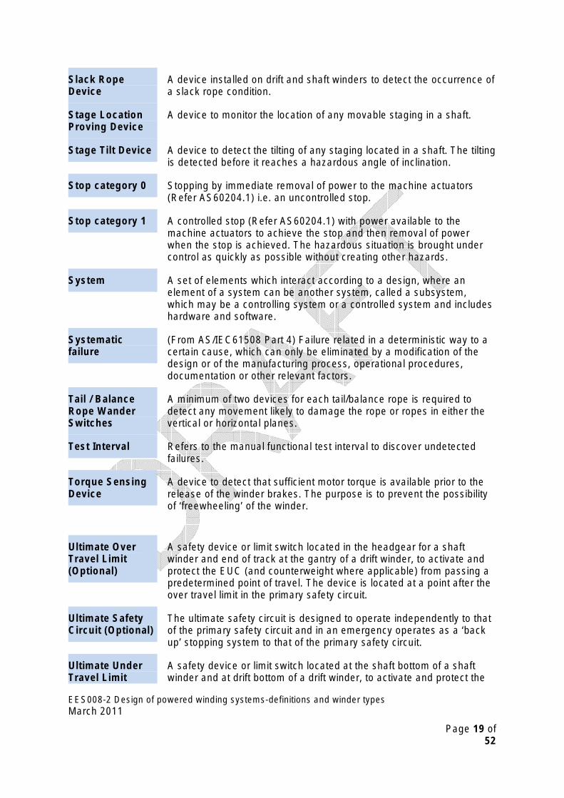
Slack Rope A device installed on drift and shaft winders to detect the occurrence of Device a slack rope condition.
Stage Location A device to monitor the location of any movable staging in a shaft. Proving Device
Stage Tilt Device A device to detect the tilting of any staging located in a shaft. The tilting is detected before it reaches a hazardous angle of inclination.
Stop category 0 Stopping by immediate removal of power to the machine actuators (Refer AS60204.1) i.e. an uncontrolled stop.
Stop category 1 A controlled stop (Refer AS60204.1) with power available to the machine actuators to achieve the stop and then removal of power when the stop is achieved. The hazardous situation is brought under control as quickly as possible without creating other hazards.
System A set of elements which interact according to a design, where an element of a system can be another system, called a subsystem, which may be a controlling system or a controlled system and includes hardware and software.
Systematic (From AS/IEC61508 Part 4) Failure related in a deterministic way to a failure certain cause, which can only be eliminated by a modification of the
design or of the manufacturing process, operational procedures, documentation or other relevant factors.
Tail / Balance A minimum of two devices for each tail/balance rope is required to Rope Wander detect any movement likely to damage the rope or ropes in either the Switches vertical or horizontal planes.
Test Interval Refers to the manual functional test interval to discover undetected
Torque Sensing
of ‘freewheeling’ of the winder.
failures.
A device to detect that sufficient motor torque is available prior to the Device release of the winder brakes. The purpose is to prevent the possibility
Ultimate Over A safety device or limit switch located in the headgear for a shaft Travel Limit winder and end of track at the gantry of a drift winder, to activate and (Optional)
Ultimate Safety Circuit (Optional)
Ultimate Under Travel Limit
protect the EUC (and counterweight where applicable) from passing a predetermined point of travel. The device is located at a point after the over travel limit in the primary safety circuit.
The ultimate safety circuit is designed to operate independently to that of the primary safety circuit and in an emergency operates as a ‘back up’ stopping system to that of the primary safety circuit.
A safety device or limit switch located at the shaft bottom of a shaft winder and at drift bottom of a drift winder, to activate and protect the
EES008-2 Design of powered winding systems-definitions and winder types March 2011
Page 19 of 52
A device to detect an over speed of the winder during periods of acceleration, constant speed and deceleration. Usually set at 5% of the
(Optional) EUC (and counterweight where applicable) from passing a predetermined point of travel. The device is located at a point after the under travel limit located in the primary safety circuit.
Winder Apparatus in which EUC’s are raised and lowered by means of a rope attached directly to the EUC, and winding onto or over a cylindrical drum, or drums; or a rack and pinion system.
Winder Drum A device driven by the winder drum to detect an over speed of 110% of Over Speed the nominal speed of the winder. Device
Winder Motor / A device driven by the winder motor shaft to detect an over speed of Motive Force 112% of the nominal speed of the winder. (hydraulic / pneumatic) Over Speed Device
Winder Speed Profile Monitoring nominal speed profile of the winder.
Winder Types 2.104.1 Double Drum Winder – Shaft - Not Fitted with a Clutch
2.104.2 Double Drum Winder – Shaft - Fitted with a Clutch,
2.104.3 Drift Winder – Single Rope.
2.104.4 Friction Winder – Shaft – Bulk Material.
2.104.5 Friction Winder – Shaft – Men and Materials.
2.104.6 Raise Climbing Winder – Rack and Pinion,
2.104.7 Shaft Sinking Winder,
2.104.8 Shaft Winder – Single Rope.
EES008-2 Design of powered winding systems-definitions and winder types March 2011
Page 20 of 52

3. Winder characteris t ics
3 . 1 Wi n d er t yp e s Modern powered winding control systems utilise encoders coupled with preprogrammed software thereby reducing the number of driven components required. However, conventional principles of control system design are still applied.
Shaft designers are reminded that the design of shafts utilising sumps is Note: discouraged. It is desired that self draining shaft bottoms be provided. There
have been several instances of people being drowned when lowered into water filled sumps. Refer to Figure 13.
Typical winder house facilities are shown in Figure 14.
3.1.1 Double Drum Winder – Shaft – Not Fitted with a clutch
A Powered Winding System installed in a single shaft, comprising two
riding cage with a counterweight, or one material tub with a counterweight or
winding drums directly coupled together.
The winder configuration can consist of two man riding cages or one man
two material tubs.
Where a material tub or tubs is/are used, one tub is fitted with man riding facilities for the purpose of shaft inspection and/or second means of egress.
There may or may not be a tail or balance rope connected between the two shaft EUC’s, and fixed guides or rope guides will be utilised for the EUC’s.
Winder controls within the conveyance are provided by radio frequency
conveyance to supply these functions.
and/or data transmission which includes communication systems. However some systems utilise a trailing cable attached to the underside of the
Some systems are capable of carrying 150 men – usually in a double cage arrangement.
Note: Currently there are no operational winders of this design installed in NSW.
EES008-2 Design of powered winding systems-definitions and winder types March 2011
Page 21 of 52

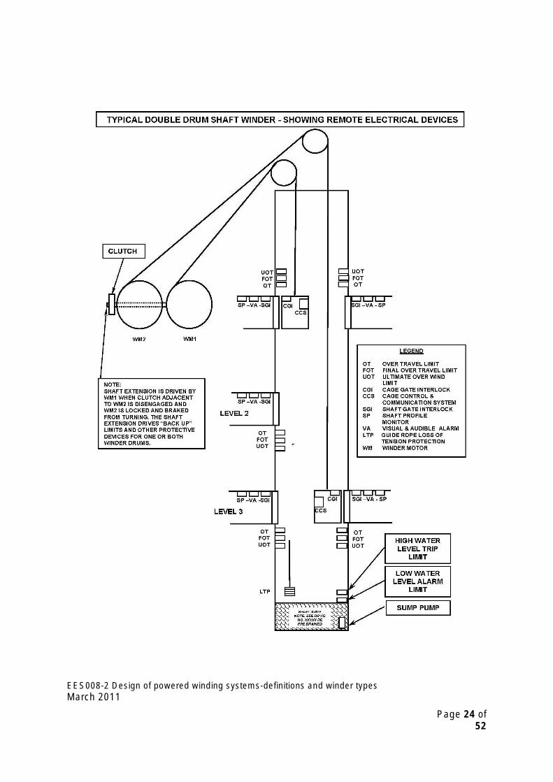
3.1.2 Double Drum Winder – Shaft – Fitted with a clutch (see figures 1 and 2)
A Powered Winding System installed in a single shaft, comprising two winding drums coupled together through a clutch. The drive shaft to one drum can be disconnected and the disconnected drum locked in position thus permitting the other drum to be operated independently to that of the locked drum.
The winder configuration can consist of two man riding cages or one man riding cage with a counterweight. This type of winder is not generally used for material winding.
There may or may not be a tail or balance rope(s) connected between the two shaft EUC’s, and fixed guides or rope guides will be will be utilised for the EUC’s.
Winder controls within the conveyance are provided by radio frequency and/or data transmission which also includes communication systems, however some systems utilise a trailing cable attached to the underside of the conveyance to supply these functions.
Some systems are capable of carrying 150 men – usually in a double cage arrangement.
Double Drum Winder
For man riding, where there is only one brake path for each drum, the clutch must be permanently engaged so that both drums rotate simultaneously and that two brake paths are available at all times.
Note: If it is required to operate each drum independently, then two brake paths must be provided for each drum and additional protective devices need to be installed to comply with EES008-3, such as drum over speed, EUC position device and ‘back up’ over wind limits etc.
EES008-2 Design of powered winding systems-definitions and winder types March 2011
Page 22 of 52

Figure 1:
EES008-2 Design of powered winding systems-definitions and winder types March 2011
Page 23 of 52
EES008-2 Design of powered winding systems-definitions and winder types March 2011
Page 24 of 52
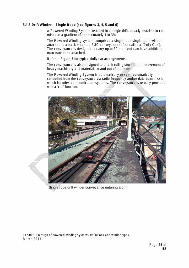
3.1.3 Drift Winder – Single Rope (see figures 3, 4, 5 and 6)
A Powered Winding System installed in a single drift, usually installed in coal mines at a gradient of approximately 1 in 3¼.
The Powered Winding system comprises a single rope single drum winder attached to a track mounted EUC conveyance (often called a “Dolly Car”). The conveyance is designed to carry up to 30 men and can have additional man transports attached.
Refer to Figure 5 for typical dolly car arrangements.
The conveyance is also designed to attach rolling stock for the movement of heavy machinery and materials in and out of the mine.
The Powered Winding System is automatically or semi automatically controlled from the conveyance via radio frequency and/or data transmission which includes communication systems. The conveyance is usually provided with a ‘call’ function.
Single rope drift winder conveyance entering a drift
EES008-2 Design of powered winding systems-definitions and winder types March 2011
Page 25 of 52

Single rope drift winder drum
EES008-2 Design of powered winding systems-definitions and winder types March 2011
Page 26 of 52

Figure 3: Drift Winder - Single Rope.
A
WINDER DRIVE
SYSTEM
GEAR BOX
SPEED DEVICE
BROKEN SHAFT / PROFILE
MONITORING
SOME WINDER DRIVES DIRECT
COUPLED
DRUM OVER SPEED DEVICE
CONVEYANCE POSITION
MONITORING
BROKEN SHAFT / PROFILE
MONITORING
‘BACK UP’ OVER WIND
LIMITS
SAFE ROPE COILING DEVICE
DISK, CALLIPER OR POST BRAKES. SERVICE AND EMERGENCY BRAKES
APPLIED TO DUAL BRAKE PATHS
DUAL BRAKE PATHS MANDATORY
DRUM PIT
TRIP & ALARM
)APPLICABLE
FLOOD DEVICE
(WHERE
T
DRIVE MOTOR MAY BE
ELECTRIC, AIR OR HYDRAULIC
HIGH SPEED BRAKE
OPTIONAL
MOTOR OVER
EES008-2 Design of powered winding systems-definitions and winder types March 2011
Page 27 of 52

Figure 4:
EES008-2 Design of powered winding systems-definitions and winder types March 2011
Page 28 of 52

Figure 5: Typical Electrical Devices Used On Conveyance (Dolly Car) of Drift Winders – Side elevation view.
HEADLIGHT ‘FLASHING’
EMERGENCY OR ‘QUICK
STOP’ LANYARD
BATTERY PACK
HEADLIGHT ‘FLASHING’
ROLLING STOCK
COUPLING
OVER SPEED DEVICE (S) MOTION
DETECTION DEVICE (S)
DUMP BRAKE
DERAIL DETECTION DEVICE (S)
DOLLY CAR CONTROLLE
LANYARD COUPLING
FOR ADDITIONAL MAN RIDING
TRANSPORTS
ELECTRICAL COUPLING
FOR ADDITIONAL MAN RIDING
TRANSPORTS
HAULAGE ROPE
ATTACHMENT
DUMP BRAKE
INBYE DIRECTION
OUTBYE DIRECTION
HYDRAULIC POWER PACK
EES008-2 Design of powered winding systems-definitions and winder types March 2011
Page 29 of 52
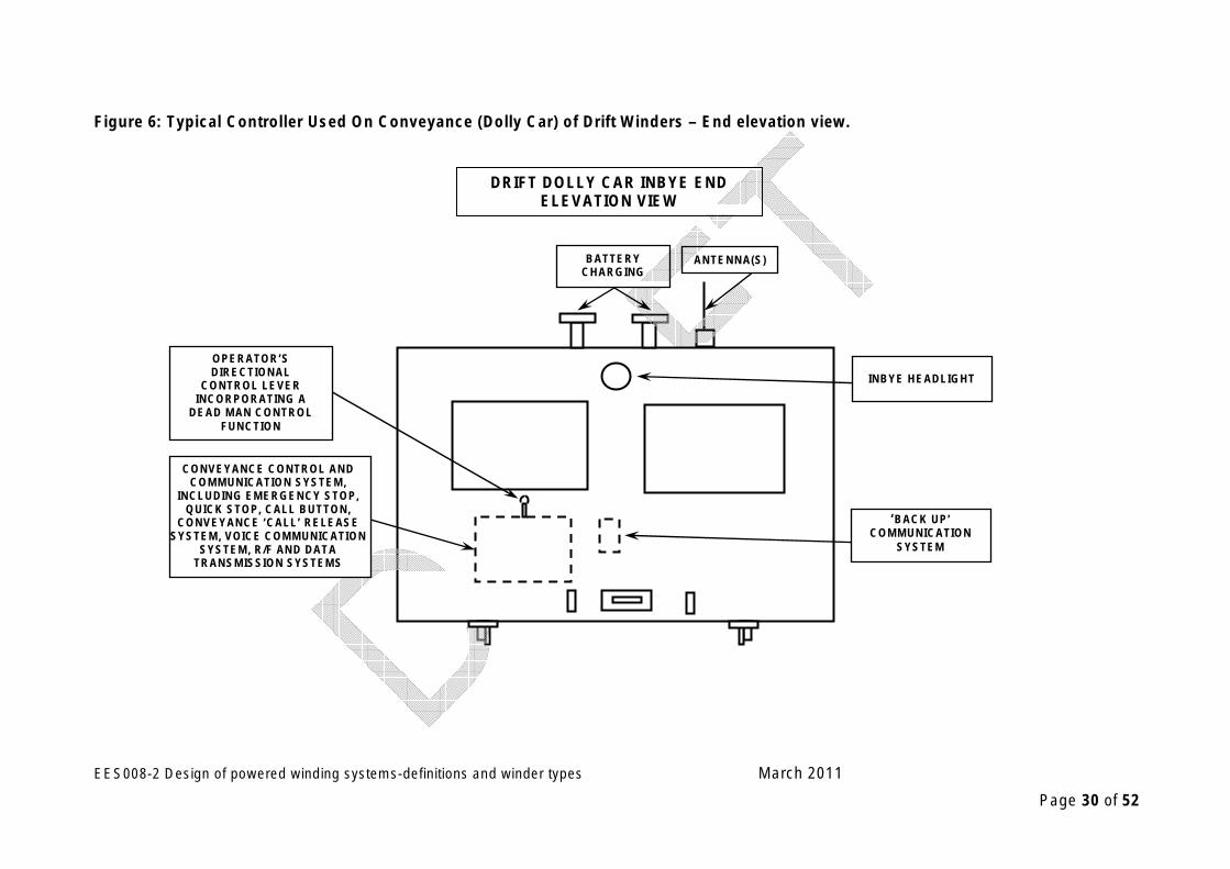
Figure 6: Typical Controller Used On Conveyance (Dolly Car) of Drift Winders – End elevation view.
‘BACK UP’ COMMUNICATION
SYSTEM
BATTERY CHARGING
RAILS
ANTENNA(S)
OPERATOR’S DIRECTIONAL
CONTROL LEVER INCORPORATING A
DEAD MAN CONTROL FUNCTION
DRIFT DOLLY CAR INBYE END ELEVATION VIEW
CONVEYANCE CONTROL AND COMMUNICATION SYSTEM,
INCLUDING EMERGENCY STOP, QUICK STOP, CALL BUTTON,
CONVEYANCE ‘CALL’ RELEASE SYSTEM, VOICE COMMUNICATION
SYSTEM, R/F AND DATA TRANSMISSION SYSTEMS
INBYE HEADLIGHT
EES008-2 Design of powered winding systems-definitions and winder types March 2011
Page 30 of 52

3.1.4 Friction Winder – Shaft – Bulk Material (see figures 7 and 8)
A Powered Winding System installed in a single shaft, comprising a single winding drum. It is often referred to as a Koepe Winder.
The winder drive system is generally tower mounted, however some are ground mounted.
The winding system comprises two to six ropes attached to the EUC conveyances. The number of ropes is dependent on the payload and depth required.
The principle of operation is that the ropes are taken over the winder drum with a half lap, thus relying on the friction between the ropes and the drum to drive the load.
The Powered Winding System normally comprises two tubs attached to each end of the winding ropes with a payload from 2 to 30 tonnes of material.
At least one material tub is fitted with man riding facilities for the purpose of shaft inspection and/or second means of egress.
One or two balance (tail) ropes are attached to the bottom of each of material tubs and fixed guides or rope guides are utilised for the EUC’s.
Loading and unloading facilities are provided at the shaft bottom and in the headframe.
Winder controls within the conveyance fitted with man riding facilities are provided by radio frequency and/or data transmission which also includes communication systems.
Refer to Figure 5 and Figure 6 in Section 3.1.5
EES008-2 Design of powered winding systems-definitions and winder types March 2011
Page 31 of 52

Figure 7 – Bulk Friction Winder for Materials Handling and Man Riding
EES008-2 Design of powered winding systems-definitions and winder types March 2011
Page 32 of 52

EES008-2 Design of powered winding systems-definitions and winder types March 2011
Page 33 of 52
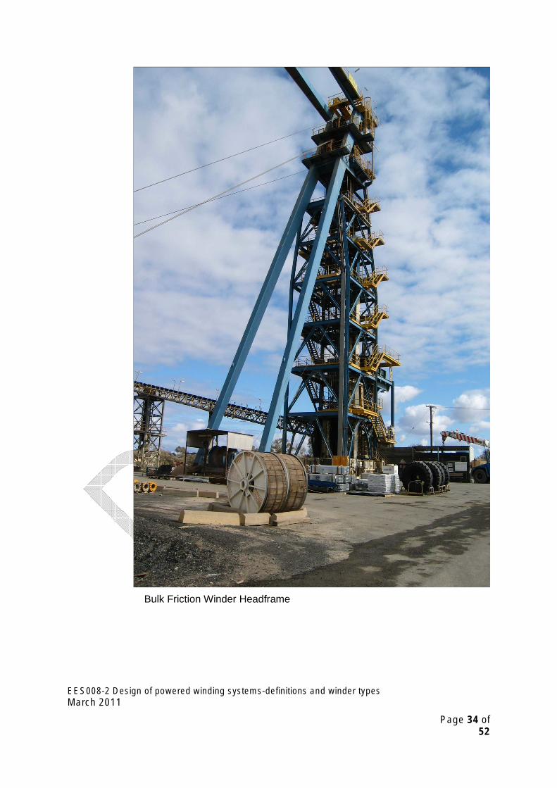
Bulk Friction Winder Headframe
EES008-2 Design of powered winding systems-definitions and winder types March 2011
Page 34 of 52
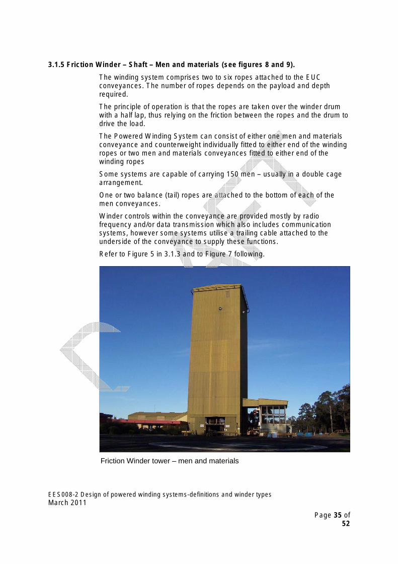
3.1.5 Friction Winder – Shaft – Men and materials (see figures 8 and 9).
The winding system comprises two to six ropes attached to the EUC conveyances. The number of ropes depends on the payload and depth required.
The principle of operation is that the ropes are taken over the winder drum with a half lap, thus relying on the friction between the ropes and the drum to drive the load.
The Powered Winding System can consist of either one men and materials conveyance and counterweight individually fitted to either end of the winding ropes or two men and materials conveyances fitted to either end of the winding ropes
Some systems are capable of carrying 150 men – usually in a double cage arrangement.
One or two balance (tail) ropes are attached to the bottom of each of the men conveyances.
Winder controls within the conveyance are provided mostly by radio frequency and/or data transmission which also includes communication systems, however some systems utilise a trailing cable attached to the underside of the conveyance to supply these functions.
Refer to Figure 5 in 3.1.3 and to Figure 7 following.
Friction Winder tower – men and materials
EES008-2 Design of powered winding systems-definitions and winder types March 2011
Page 35 of 52
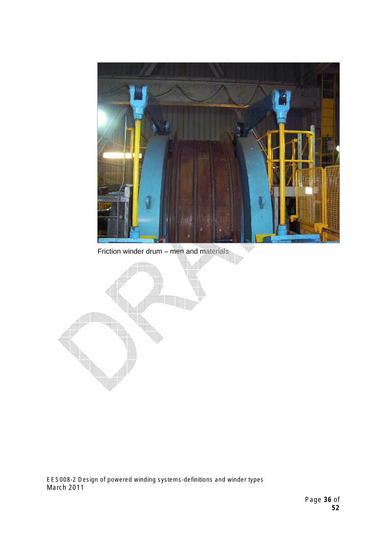
Friction winder drum – men and materials
EES008-2 Design of powered winding systems-definitions and winder types March 2011
Page 36 of 52

Figure 8: Typical Friction Shaft Winder Drive System Showing Electrical Devices.
WINDER DRIVE
SYSTEM
GEAR BOX
MOTOR OVER
SPEED DEVICE
BROKEN SHAFT/
PROFILE MONITORING
SOME WINDER DRIVES DIRECT
COUPLED DRUM OVER SPEED
DEVICE(S)
CONVEYANCE POSITION DEVICE
BROKEN SHAFT / PROFILE
MONITORING
‘BACK UP’ OVER WIND
LIMITS ROPE SLIP DETECTION
DEVICE
DISK, CALLIPER OR POST BRAKES. SERVICE AND EMERGENCY BRAKES
APPLIED TO DUAL BRAKE PATHS
ROPE CREEP CORRECTION
DEVICE DRUM PIT FLOOD DEVICE - TRIP &
ALARM (GROUND MOUNTED WINDER
DRIVES)
EES008-2 Design of powered winding systems-definitions and winder types March 2011
Page 37 of 52

Figure 9: Typical Men and Materials Friction Winder
EES008-2 Design of powered winding systems-definitions and winder types March 2011
Page 38 of 52

EES008-2 Design of powered winding systems-definitions and winder types March 2011
Page 39 of 52
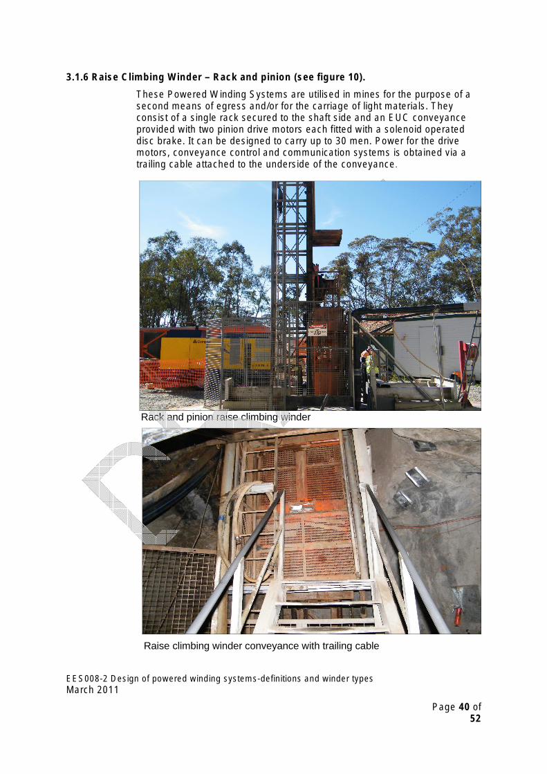
3.1.6 Raise Climbing Winder – Rack and pinion (see figure 10).
These Powered Winding Systems are utilised in mines for the purpose of a second means of egress and/or for the carriage of light materials. They consist of a single rack secured to the shaft side and an EUC conveyance provided with two pinion drive motors each fitted with a solenoid operated disc brake. It can be designed to carry up to 30 men. Power for the drive motors, conveyance control and communication systems is obtained via a trailing cable attached to the underside of the conveyance.
Rack and pinion raise climbing winder
Raise climbing winder conveyance with trailing cable
EES008-2 Design of powered winding systems-definitions and winder types March 2011
Page 40 of 52

Figure 10: Typical Rack and Pinion Hoist Showing Remote Electrical Devices.
HOIST RACK
SHAFT ENTRY GATE, ELECTRICAL AND
MECHANICAL INTERLOCKS
ULTIMATE, FINAL AND OVER
TRAVEL LIMITS
POWER SUPPLY CABLE TO CAGE
CAGE GATE, ELECTRICAL AND MECHANICAL
INTERLOCKS
SHAFT ENTRY GATE, ELECTRICAL AND
MECHANICAL INTERLOCKS
CAGE CABLE ANCHOR REEL
POWER SUPPLY CABLE TO CAGE
TWIN DRIVE MOTORS FITTED WITH SOLENOID BRAKES
OVER SPEED DEVICE
POWER SUPPLY CABLE WANDER LIMIT
CAGE CONTROL & COMMUNICATION
SYSTEM
ULTIMATE, FINAL AND NORMAL OVER TRAVEL
LIMITS
EES008-2 Design of powered winding systems-definitions and winder types March 2011
Page 41 of 52
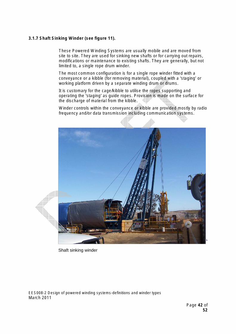
3.1.7 Shaft Sinking Winder (see figure 11).
These Powered Winding Systems are usually mobile and are moved from site to site. They are used for sinking new shafts or for carrying out repairs, modifications or maintenance to existing shafts. They are generally, but not limited to, a single rope drum winder.
The most common configuration is for a single rope winder fitted with a conveyance or a kibble (for removing material), coupled with a ‘staging’ or working platform driven by a separate winding drum or drums.
It is customary for the cage/kibble to utilise the ropes supporting and operating the ‘staging’ as guide ropes. Provision is made on the surface for the discharge of material from the kibble.
Winder controls within the conveyance or kibble are provided mostly by radio frequency and/or data transmission including communication systems.
` Shaft sinking winder
EES008-2 Design of powered winding systems-definitions and winder types March 2011
Page 42 of 52

Cable drum of mobile shaft sinking winder
EES008-2 Design of powered winding systems-definitions and winder types March 2011
Page 43 of 52

Figure 11:
EES008-2 Design of powered winding systems-definitions and winder types March 2011
Page 44 of 52

3.1.8 Shaft Winder – Single Rope (see figures 12 and 13)
A Powered Winding System installed in a shaft, comprising a single rope single drum winder attached to a conveyance. The conveyance can be designed to operate as a man only or men and materials configuration and can carry up to 150 men (double cage) and is often utilised as a second means of egress. Fixed or rope guides are used for the EUC conveyance.
The Powered Winding System is controlled from within the conveyance via radio frequency and/or data transmission which includes communication systems. Control and communication systems are sometimes supplied via a trailing cable attached to the underside of the conveyance. The Winding Systems are sometimes provided with a ‘call’ function.
Single rope shaft winder
Drum of single rope shaft winder
EES008-2 Design of powered winding systems-definitions and winder types March 2011
Page 45 of 52

Figure 12: Typical Drum Drift Winder and Single Rope Shaft Winder Drive System Showing Electrical Devices.
A
WINDER DRIVE
SYSTEM
GEAR BOX
DEVICE
BROKEN SHAFT / PROFILE
MONITORING
SOME WINDER DRIVES DIRECT
COUPLED
DRUM OVER SPEED DEVICE
CONVEYANCE POSITION
MONITORING
BROKEN SHAFT / PROFILE
MONITORING
‘BACK UP’ OVER WIND
LIMITS
SAFE ROPE COILING DEVICE
DISK, CALLIPER OR POST BRAKES. SERVICE AND EMERGENCY BRAKES
APPLIED TO DUAL BRAKE PATHS
DUAL BRAKE PATHS MANDATORY
DRUM PIT
)
DRIVE MOTOR MAY BE
ELECTRIC, AIR OR HYDRAULIC
APPLICABLE
FLOOD DEVICE TRIP & ALARM
(WHERE
T
HIGH SPEED BRAKE
OPTIONAL
MOTOR OVER
SPEED
EES008-2 Design of powered winding systems-definitions and winder types March 2011
Page 46 of 52

Figure 13:
EES008-2 Design of powered winding systems-definitions and winder types March 2011
Page 47 of 52
3 . 2 Wi n d er Dr i ve S ys t e m s
Ward Leonard, thyristor, vvvf, squirrel cage induction motor, slipring induction motor, hydraulic, air.
3 . 3 Wi n d er Br a k e T yp e s
Disc, drum, calliper, pressure applied spring back up calliper. Post, suspended post, parallel motion – all should be fail to safety and are spring or counterweight applied.
Band brakes shall not be used.
3 . 4 Wi n d er Br a k e O p er a t i n g M ed i u ms
Hydraulic, air, electro magnetic thrustor.
EES008-2 Design of powered winding systems-definitions and winder types March 2011
Page 48 of 52
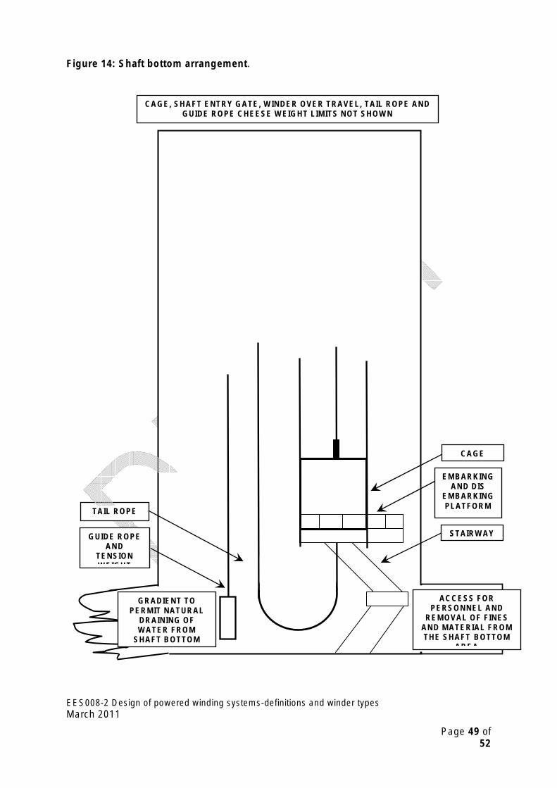
Figure 14: Shaft bottom arrangement.
CAGE, SHAFT ENTRY GATE, WINDER OVER TRAVEL, TAIL ROPE AND GUIDE ROPE CHEESE WEIGHT LIMITS NOT SHOWN
GRADIENT TO PERMIT NATURAL
DRAINING OF WATER FROM
SHAFT BOTTOM
ACCESS FOR PERSONNEL AND
REMOVAL OF FINES AND MATERIAL FROM THE SHAFT BOTTOM
AREA
GUIDE ROPE AND
TENSION WEIGHT
TAIL ROPE
CAGE
EMBARKING AND DIS
EMBARKING PLATFORM
STAIRWAY
EES008-2 Design of powered winding systems-definitions and winder types March 2011
Page 49 of 52

Figure 15: Mine Winder House – Typical Facilities.
MINE WINDER SIL RATED CONTROL SYSTEM
WINDER SIGNALLING AND / OR
COMMUNICATION SYSTEM INCLUDING
‘BACK UP’ COMMUNICATION
SYSTEMS
CONDITION MONITORING FACILITIES
CONVEYANCE POSITION
INDICATOR
FACILITIES FOR LOGGING ANY OPERATION OF
THE EMERGENCY STOPPING SYSTEM
VISUAL AND AUDIBLE ALARMS
PROVISION FOR MANUAL OPERATION
OF WINDER INCLUDING DEAD MAN CONTROL
(WHERE APPROPRIATE)
STATIC AND DYNAMIC BRAKE TESTING
FACILITIES INCLUDING DEAD
MAN CONTROL
OVER WIND ‘BACK OUT’ FACILITIES
SLACK ROPE ‘BACK
OUT’ FACILITIES
UN SAFE COILING ‘BACK
OUT’ FACILITIES
EMERGENCY AND OR
QUICK STOP FACILITIES
MINE WINDER ‘CALL’
FACILITIES
WINDER HOUSE FIRE BRAKING ENVIRONMENTAL SUPPRESSION HYDRAULIC
CONTROL SYSTEM SYSTEM POWER PACK
EES008-2 Design of powered winding systems-definitions and winder types March 2011
Page 50 of 52

4. Appendices�
F e e d ba c k S h ee t Your comment on this Technical Reference is essential for its review and improvement.
Please make a copy of this Feedback Sheet and send your comments to: The Senior Inspector of Electrical Engineering Mine Safety Operations Industry and Investment NSW PO Box 344 Hunter Region Mail Centre NSW 2310 Phone: (02) 4931 6641 Fax: (02) 4931 6790
How did you use (or intend to use) this Guideline?
What did you find most useful about the Guideline?
What did you find least useful about the Guideline?
Do you have any suggestions to improve the Guideline?
Thank you for completing and returning the Feedback Sheet.
EES008-2 Design of powered winding systems-definitions and winder types March 2011
Page 51 of 52
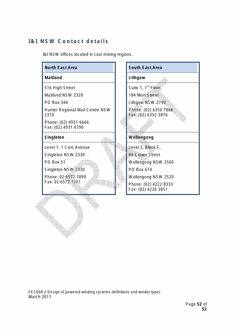
I & I N SW C o n ta c t de ta i l s
I&I NSW offices located in coal mining regions.
North East Area South East Area
Maitland Lithgow
516 High Street
Maitland NSW 2320
PO Box 344
Hunter Regional Mail Centre NSW 2310
Phone: (02) 4931 6666 Fax: (02) 4931 6790
Suite 1, 1st
Fax: (02) 6352 3876
Singleton
Level 1, 1 Civic Avenue
Singleton NSW 2330
PO Box 51
Level 3, Block F,
84 Crown Street
Wollongong NSW 2500
PO Box 674
Wollongong NSW 2520
Phone: (02) 4222 8333 Fax: (02) 4226 3851
Singleton NSW 2330
Phone: 02 6572 1899 Fax: 02 6572 1201
Lithgow NSW 2790
Phone: (02) 6350 7888
Wollongong
Floor,
184 Mort Street
EES008-2 Design of powered winding systems-definitions and winder types March 2011
Page 52 of 52