electrical level 4
TRANSCRIPT

Electrical Level 4
Medium-Voltage Terminations/Splices 26411-14

Objectives
When trainees have completed this lesson, they should
be able to do the following:
1. Recognize the factors related to motor reliability
and life span.
2. Measure motor winding insulation resistance and
compensate for temperature.
3. Identify motors needing replacement.
Medium-Voltage Terminations/Splices 26411-14

Performance Task
Prepare a cable and complete a splice or
stress cone.
Medium-Voltage Terminations/Splices 26411-14

1.0.0 – 1.1.0
Medium-Voltage Terminations/Splices 26411-14
Introduction

2.0.0 – 2.5.0
Medium-Voltage Terminations/Splices 26411-14
Medium-Voltage Power Cable

2.0.0 – 2.5.0
Medium-Voltage Terminations/Splices 26411-14
Basic Components of
Medium-Voltage Cable
Each cable component is essential to proper system
performance and must be considered when making a
splice or termination.

2.0.0 – 2.5.0
Medium-Voltage Terminations/Splices 26411-14
Basic Cable Configurations
• Concentric stranding is not used in shielded power cables because the
extruded strand shielding is difficult to remove when making field connections.
• Compressed stranding is reduced to 97% of concentric conductor diameters.
The extruded strand shielding does not penetrate and is easily removable.
• Compact stranding is reduced to 90% of concentric conductor diameters and
should be sized down for molded rubber devices.
• Solid wire is not used in industrial shielded power cable.

2.0.0 – 2.5.0
Medium-Voltage Terminations/Splices 26411-14
Strand Shielding
• Strand shielding is the
semi-conductive
(semi-con) layer
between the conductor
and the insulation.
• Strand shielding fills
the air voids between
conductors and
eliminates the insulation-
degrading corona
discharges caused by
the ionization of air.

2.0.0 – 2.5.0
Medium-Voltage Terminations/Splices 26411-14
Insulation
Shield System
• The outer shielding contains a
semi-conductive layer under a
metallic layer.
• The shield system provides
even stress distribution and
protects the cable from induced
voltages and radio interference.
It also reduces shock hazard
and provides a ground path for
leakage and fault currents.

2.0.0 – 2.5.0
Medium-Voltage Terminations/Splices 26411-14
Jacket and Insulation
• The outer jacket provides mechanical protection and a
moisture barrier.
• Typical materials used for cable jackets include PVC,
neoprene, and lead. Industrial three-conductor cables
frequently include an armored sheath.

3.0.0 – 3.2.4
Medium-Voltage Terminations/Splices 26411-14
Splicing I • Splices should be avoided whenever possible, but may be
required due to cable damage or failure, insufficient length or
room for the proper bending radius, excessive twisting, or taps.
• The basic steps in a cable splice include preparing the cable,
joining the conductors with connectors, reinsulating,
reshielding, and rejacketing.

3.0.0 – 3.2.4
Medium-Voltage Terminations/Splices 26411-14
Think About It: Mechanical Connectors
Could you use the connectors shown here to make
a high-voltage connection?

3.0.0 – 3.2.4
Medium-Voltage Terminations/Splices 26411-14
High-Voltage Cable
Construction

3.0.0 – 3.2.4
Medium-Voltage Terminations/Splices 26411-14
Recommended Cable Preparation
Procedures for an Inline Splice
• When preparing cable for a splice, train the cable and cut it
carefully so the end is square.
• Remove the jacket and nonmetallic filler tape, cable metallic
shielding, semi-conductive material, and cable insulation to
the dimensions indicated. Take care not to nick the conductor.

3.0.0 – 3.2.4
Medium-Voltage Terminations/Splices 26411-14
Wire Shield Procedure
Follow the procedure shown here if using shielded wire cable.

3.0.0 – 3.2.4
Medium-Voltage Terminations/Splices 26411-14
Connecting Conductors
• Join the cables using an appropriate connector. Use a crimp
connector to join thermoplastic-insulated cables.
• Fill the conductor indents with semi-conductive tape, as
shown here.

3.0.0 – 3.2.4
Medium-Voltage Terminations/Splices 26411-14
Applying Primary Insulation
• Apply medium-voltage splicing tape to replace the primary
conductor insulation.
• Various types and layers of tape may be required. Follow
the manufacturer’s instructions for the product in use.

3.0.0 – 3.2.4
Medium-Voltage Terminations/Splices 26411-14
Summary of an Inline Tape Splice Next Session…
Splicing II

3.3.0 – 3.6.0
Medium-Voltage Terminations/Splices 26411-14
Splicing II

3.3.0 – 3.6.0
Medium-Voltage Terminations/Splices 26411-14
Preparing the Cables
• Manufactured termination/splice kits include cable preparation
materials, semi-conductor, stress control, jacketing, sealing,
and grounding. Both heat-shrink and cold-shrink kits are
available.
• To use a quick inline splicing kit, select the correct kit for the
cable diameter, cut back the cable as specified, and clean the
cable jacket for the length of the tubes.

3.3.0 – 3.6.0
Medium-Voltage Terminations/Splices 26411-14
Placing the Nested Tubes on the Cable
• Place the nested tubes and the rejacketing tube over
the cables as shown.
• Protect the tube from the sharp ends of the conductor
as they are placed over the cable.

3.3.0 – 3.6.0
Medium-Voltage Terminations/Splices 26411-14
Installing the Connector
• Install the connector.
• Wipe the insulation down using an oil-free solvent.
Note that some solvents do not evaporate quickly and
must be removed using a clean, lint-free cloth.

3.3.0 – 3.6.0
Medium-Voltage Terminations/Splices 26411-14
Installing the Stress Relief Material
• Tightly wrap the exposed conductor with the stress relief material
(SRM), making sure to fill all gaps and low spots around the
connector. Also install SRM over the semi-con cutback areas.
• If the connector diameter is larger than the insulation diameter,
apply two overlapped layers of SRM along the length of the
entire connector.

3.3.0 – 3.6.0
Medium-Voltage Terminations/Splices 26411-14
Shrinking the Stress Control Tube
• Center the stress control tube over the splice and shrink it into
place.
• Follow all safety precautions for torch use. Use a smooth
brushing motion and keep the flame moving to avoid damage.
Unless otherwise indicated, start at the center of the tube and
move outward.

3.3.0 – 3.6.0
Medium-Voltage Terminations/Splices 26411-14
Shrinking the Insulating Tube
Position the insulating tube over the stress control tube and
shrink it into place.

3.3.0 – 3.6.0
Medium-Voltage Terminations/Splices 26411-14
Applying Sealant
• Apply sealant to the tube ends to provide a positive
environmental seal.
• Build the sealant to the level of the insulating tube.

3.3.0 – 3.6.0
Medium-Voltage Terminations/Splices 26411-14
Shrinking the Insulating/Conductive Tube
Position the insulating/conductive tube over the insulating
tube and seal the ends before shrinking into place.

3.3.0 – 3.6.0
Medium-Voltage Terminations/Splices 26411-14
Installing Metallic Shielding Mesh
• Install metallic shielding mesh using manufacturer-supplied
constant-tension clamps for metallic tape shielding.
• Use crimp connectors for wire shielding.

3.3.0 – 3.6.0
Medium-Voltage Terminations/Splices 26411-14
Shrinking the Rejacketing Tube
and Checking for Adhesive Flow
• Position the rejacketing tube and shrink it into place.
• Check the ends for correct adhesive flow.

3.3.0 – 3.6.0
Medium-Voltage Terminations/Splices 26411-14
Cable Preparation Details
• To use a cold-shrink quick inline splicing kit, clean the cable
jacket, then remove the specified lengths of metallic shielding,
cable semi-conductive material, and insulation.
• Clean the exposed insulation using the cleaning pads in the kit.
Do not use solvent or abrasive on the semi-con layer.

3.3.0 – 3.6.0
Medium-Voltage Terminations/Splices 26411-14
Components of a Ribbon
Shielding Cable Splice
• Apply two layers of semi-conductive tape as shown. Leave a
smooth leading edge and tape back to the starting position.
• Apply a layer of orange vinyl tape adhesive side up on one
of the cables over the metallic shield.

3.3.0 – 3.6.0
Medium-Voltage Terminations/Splices 26411-14
Installing PST Cold-Shrink Insulator
• Slide the longer PST insulator over the jacket with the
orange tape and the shorter PST onto the other jacket.
• Lubricate the exposed insulation with silicone grease.

3.3.0 – 3.6.0
Medium-Voltage Terminations/Splices 26411-14
Wrapping No. 13 Tape onto the Cable
• Lubricate the splice bore with silicone grease and install
it onto the orange-taped cable, leaving the conductor
exposed for the connector.
• Install the crimped connector.

3.3.0 – 3.6.0
Medium-Voltage Terminations/Splices 26411-14
Use Bumps Formed on Splice Ends
as Guides for Centering
• Slide the splice body into its final position over the
connector, using the bumps formed on the splice ends
as guides for centering.
• Wipe off any remaining silicone grease.

3.3.0 – 3.6.0
Medium-Voltage Terminations/Splices 26411-14
Wrap Vinyl Tape at
Each End of the Splice Body
• The shield continuity assembly must be installed after
reinsulating a splice.
• Position the assembly over the splice and hold it in place
using pieces of vinyl tape at each end.

3.3.0 – 3.6.0
Medium-Voltage Terminations/Splices 26411-14
Form the Shield Continuity Strap
Over the Splice Shoulder on Each Side
• Form the shield continuity strap over the splice shoulder
on each side.
• Install and seal per the manufacturer’s instructions.

3.3.0 – 3.6.0
Medium-Voltage Terminations/Splices 26411-14
Remove Core by
Unwinding Counterclockwise • Position each PST so its leading edge will butt against the splice
grounding eye.
• Remove the core by unwinding it counterclockwise and tugging.
Performance Task
This session will conclude with trainees preparing a cable and completing a splice
or stress cone.
Next Session…
Terminations

4.0.0 – 4.2.1
Medium-Voltage Terminations/Splices 26411-14
Terminations • Class 1 terminations provide electric stress control, external leakage insulation
between the conductor(s) and ground, and an environmental seal.
• Class 2 terminations provide electric stress control and external leakage
insulation between the conductor(s) and ground, but no environmental seal.
• Class 3 terminations only provide electric stress control.

4.0.0 – 4.2.1
Medium-Voltage Terminations/Splices 26411-14
Removing the Shield

4.0.0 – 4.2.1
Medium-Voltage Terminations/Splices 26411-14
Geometric Stress Control
Geometric stress control involves an extension of the shielding,
expanding the diameter at which the terminating discontinuity
occurs and thereby reducing the stress.

4.0.0 – 4.2.1
Medium-Voltage Terminations/Splices 26411-14
Equalizing Electrical Stresses
With the capacitive method of stress control, the lines of
electrical flux are regulated to equalize the electrical stresses
along the entire area where the shielding has been removed.

4.0.0 – 4.2.1
Medium-Voltage Terminations/Splices 26411-14
Insulation Classes and BIL Ratings

4.0.0 – 4.2.1
Medium-Voltage Terminations/Splices 26411-14
A Terminator May Be
Considered an Insulator
• A termination can be considered an insulator having a
voltage drop between the conductor and the shield.
• The magnitude of the leakage current is inversely
proportional to the resistance on the insulation surface.

4.0.0 – 4.2.1
Medium-Voltage Terminations/Splices 26411-14
Think About It: Disc Assemblies
What is the purpose of the large circular assemblies
shown in this picture?

5.0.0 – 5.8.0
Medium-Voltage Terminations/Splices 26411-14
High-Potential (Hi-Pot) Testing
• High-potential (hi-pot)
tests can be used to
indicate insulation cracks,
voids, or discontinuity;
excessive moisture or
dirt; and faulty splices
or terminations.
• If a leakage current-
versus-voltage test
depicts the general curve
shown here, the tested
equipment can be
considered satisfactory.

5.0.0 – 5.8.0
Medium-Voltage Terminations/Splices 26411-14
Current-Versus-Time Curve
• A leakage current-versus-time test may be used on long cable runs or
with rotating machinery having a high capacitance between windings or
from winding to frame.
• If a leakage current-versus-time test depicts the general curve shown
here, the tested equipment can be considered satisfactory.
5.0.0 – 5.8.0
Medium-Voltage Terminations/Splices 26411-14
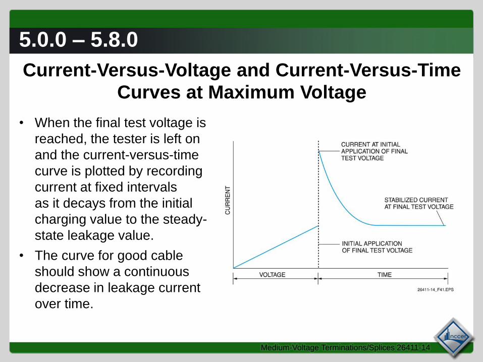
Current-Versus-Voltage and Current-Versus-Time
Curves at Maximum Voltage
• When the final test voltage is
reached, the tester is left on
and the current-versus-time
curve is plotted by recording
current at fixed intervals
as it decays from the initial
charging value to the steady-
state leakage value.
• The curve for good cable
should show a continuous
decrease in leakage current
over time.

5.0.0 – 5.8.0
Medium-Voltage Terminations/Splices 26411-14
Faulty Insulation
Any increase in current during this test would indicate a
bad cable or machine.

5.0.0 – 5.8.0
Medium-Voltage Terminations/Splices 26411-14
Hi-Pot Connections for Testing
Multiple-Conductor Shielded Cable

5.0.0 – 5.8.0
Medium-Voltage Terminations/Splices 26411-14
Testing a High-Voltage Winding to a Grounded Core
or Case with a Secondary Winding to a Bypass

5.0.0 – 5.8.0
Medium-Voltage Terminations/Splices 26411-14
Testing a High-Voltage Winding to a Low-Voltage
Winding with the Ground and Case to a Bypass

5.0.0 – 5.8.0
Medium-Voltage Terminations/Splices 26411-14
Measuring BushingInternal Leakage

5.0.0 – 5.8.0
Medium-Voltage Terminations/Splices 26411-14
Measuring BushingSurface Leakage

5.0.0 – 5.8.0
Medium-Voltage Terminations/Splices 26411-14
Testing Cable Insulation Between
One Conductor and the Shield

5.0.0 – 5.8.0
Medium-Voltage Terminations/Splices 26411-14
Testing Cable Insulation Between One
Conductor and All Others and the Shield

5.0.0 – 5.8.0
Medium-Voltage Terminations/Splices 26411-14
Testing Cable Insulation Between Conductors

5.0.0 – 5.8.0
Medium-Voltage Terminations/Splices 26411-14
Simplified Hi-Pot Tester Output Circuit Diagram

5.0.0 – 5.8.0
Medium-Voltage Terminations/Splices 26411-14
Corona Shield
A corona guard ring and/or guard shield is used to
intercept corona current before it reaches ground.
Next Session…
Wrap Up

Wrap Up
– Write important things learned during class
– Write questions you have about the material
– Write thought you had about the material
Medium-Voltage Terminations/Splices 26411-14

Next Session…
MODULE EXAM
Review the complete module to prepare
for the module exam. Complete the Module
Review as a study aid.
Medium-Voltage Terminations/Splices 26411-14