electrical safety manual - group - liberty€¦ · electrical safety manual document:...
TRANSCRIPT

Electrical Safety Manual
Document: OST-OHS-ELEC-PRO-001 Version: 4.0
Authorised By: OneSteel Whyalla ESN Date Reviewed: 13/12/2016 OneSteel WHYALLA Intranet version is the only controlled version Page 1 of 118
ELECTRICAL SAFETY MANUAL

Electrical Safety Manual
Document: OST-OHS-ELEC-PRO-001 Version: 4.0
Authorised By: OneSteel Whyalla ESN Date Reviewed: 13/12/2016 OneSteel WHYALLA Intranet version is the only controlled version Page 2 of 118
Contents
INTRODUCTION ..................................................................................................................................... 7
SAFETY OF ELECTRICAL WORKERS ................................................................................................ 7
FUNDAMENTAL ELECTRICAL SAFETY RULES .............................................................................. 7
CONTROL AND DISTRIBUTION OF THIS MANUAL ....................................................................... 8
DEFINITIONS OF TERMS USED IN THIS MANUAL ......................................................................... 8
1 Works Cited ......................................................................................................................... 17
2 PART 1 – ELECTRICAL SAFETY; GENERAL ............................................................... 18
2.1 CONTROL OF ELECTRICAL HAZARDS ....................................................................... 18
2.1.1 Electrical Safety is YOUR Responsibility ............................................................................ 18 2.1.2 Risk Management ................................................................................................................. 18
2.2 ACCIDENTS and EMERGENCIES ................................................................................... 19
2.2.1 Electrical Shock and Emergency Procedures ...................................................................... 19 2.2.2 Arc Fault Injuries and Damage ........................................................................................... 21 2.2.3 Reporting Incidents / Accidents ........................................................................................... 22
2.2.4 Breathing Apparatus ............................................................................................................ 22 2.2.5 Emergency Procedures ........................................................................................................ 23
2.2.6 Resuscitation for Electric Shock .......................................................................................... 24 2.2.7 Effect of current through the body ....................................................................................... 25 2.2.8 Time/current zones of effects of ac currents through the human body ................................ 26
2.3 TRAINING and SUPERVISING PERSONNEL ................................................................ 27
2.3.1 Mandatory Training for Electrical Personnel ..................................................................... 27
2.3.2 Electrical Apprentices & Cadets ......................................................................................... 27
2.3.3 Guide: First / Second Year Electrical Apprentice ............................................................... 29
2.3.4 Guide: Third Year Apprentices ............................................................................................ 29 2.3.5 Guide: Fourth Year Apprentices .......................................................................................... 29
2.3.6 Limitation on Overtime, Shiftwork and Strikes for Apprentices .......................................... 30 2.3.7 Guidelines for Apprentices to Tradesperson ratio............................................................... 30
2.3.8 Electrical Apprentices & Cadets – Summary Table ............................................................ 31 2.3.9 Guide to achieving electrical competency ........................................................................... 32 2.3.10 Responsibilities for the Provision of Training for Apprentices and Cadets ........................ 33
2.4 PREPARING FOR ELECTRICAL WORK ........................................................................ 35
2.4.1 Electrical Work General ...................................................................................................... 35
2.4.2 Plant Area Inductions .......................................................................................................... 35 2.4.3 Planning an Installation ...................................................................................................... 36 2.4.4 Commencing Work ............................................................................................................... 36
2.4.5 Inspecting, testing and Compliance Certificate (CoC, CCEW) ........................................... 36 2.4.6 Policies, Procedures, Work Instructions & Reference List ................................................. 37
2.5 ISOLATION ........................................................................................................................ 39
2.5.1 Isolation for Personal Protection (Lockout) ........................................................................ 39
2.5.2 Test Before You Touch ......................................................................................................... 39

Electrical Safety Manual
Document: OST-OHS-ELEC-PRO-001 Version: 4.0
Authorised By: OneSteel Whyalla ESN Date Reviewed: 13/12/2016 OneSteel WHYALLA Intranet version is the only controlled version Page 3 of 118
2.5.3 Multiple and Emergency Supplies, isolating ....................................................................... 40 2.5.4 Neutral Conductors, Electric Shock .................................................................................... 40
2.5.5 Isolator operation ................................................................................................................ 40 2.5.6 Isolating Specific Equipment ............................................................................................... 41
2.5.7 Test before you touch checklist ............................................................................................ 43 2.5.8 Test before you touch flowchart ........................................................................................... 44
2.6 WORKING ON or NEAR ELECTRICAL EQUIPMENT and SERVICES ....................... 46
2.6.1 Fundamental Electrical Safety Rules for work on or near Electrical Equipment and
Services ............................................................................................................................... 46
2.6.2 Emergencies ......................................................................................................................... 47 2.6.3 Awareness of electrical equipment/services when working ................................................. 50 2.6.4 PPE / Dress for Electrical Work .......................................................................................... 53 2.6.5 Authorisation for specific electrical work / tasks ................................................................ 56 2.6.6 Work in Switchrooms ........................................................................................................... 57
2.6.7 Non Electrical work near live exposed electrical equipment .............................................. 58
2.6.8 Electrical work near live exposed electrical equipment ...................................................... 59
2.6.9 Work and storage near overhead power lines ..................................................................... 59 2.6.10 Work on Extra Low Voltage (ELV) ...................................................................................... 60 2.6.11 Approval for work on / near electrical equipment ............................................................... 61 2.6.12 Work near live conductors (general) ................................................................................... 62
2.6.13 Work near power lines ......................................................................................................... 63 2.6.14 Open panels risk control (guide) ......................................................................................... 64
2.6.15 Open panels risk control ...................................................................................................... 67
2.7 Electrical TESTING............................................................................................................. 69
2.7.1 Electrical Testing, General .................................................................................................. 69
2.7.2 Electrical Testing Safety ...................................................................................................... 69 2.7.3 Test Meters ........................................................................................................................... 71
2.7.4 Modification and Process Change Control ......................................................................... 72 2.7.5 In Service Testing of Portable Electrical Equipment .......................................................... 72
2.7.6 Mandatory regular testing of fixed equipment..................................................................... 73
2.8 EARTHING, POWER and LIGHTING .............................................................................. 74
2.8.1 Earthing Equipment Before Electrical Work ....................................................................... 74
2.8.2 Primary Protection from an Earth Fault ............................................................................. 74 2.8.3 Supplementary Protection from an Earth Fault by RCD (Residual Current Device) ......... 74
2.8.4 Power Distribution............................................................................................................... 76 2.8.5 Lighting ................................................................................................................................ 76
2.9 HIGH VOLTAGE SAFETY................................................................................................ 79
2.9.1 High Voltage Safety, General .............................................................................................. 79 2.9.2 High Voltage Maintenance .................................................................................................. 79
2.9.3 High Voltage Hazards.......................................................................................................... 80 2.9.4 Step and Touch Potential ..................................................................................................... 81
2.10 SPECIAL SITUATIONS ..................................................................................................... 82
2.10.1 Construction Sites ................................................................................................................ 82 2.10.2 Adverse Environments ......................................................................................................... 82 2.10.3 Confined Space .................................................................................................................... 83
Electrical Safety Manual
Document: OST-OHS-ELEC-PRO-001 Version: 4.0
Authorised By: OneSteel Whyalla ESN Date Reviewed: 13/12/2016 OneSteel WHYALLA Intranet version is the only controlled version Page 4 of 118
2.10.4 Hazard Zones (harmful gas atmosphere)* .......................................................................... 83 2.10.5 Hazard Areas ....................................................................................................................... 83
2.10.6 Energy Radiating Devices.................................................................................................... 86 2.10.7 Communication devices, Mobile Telephones, etc ................................................................ 87
2.10.8 Emergency Equipment ......................................................................................................... 87 2.10.9 Redundant Equipment Removal ........................................................................................... 87
2.11 IDENTIFICATION AND LABELLING ............................................................................ 89
2.11.1 Identification and Labelling, General.................................................................................. 89 2.11.2 Identification of control and signal units ............................................................................. 90
2.11.3 Safety signs for Hazard Identification ................................................................................. 91 2.11.4 Identification of live exposed conductors ............................................................................ 92
2.12 PORTABLE ELECTRICAL EQUIPMENT ....................................................................... 93
2.12.1 Portable / Movable Electrical Equipment ........................................................................... 93 2.12.2 Flexible Supply and Extension Cords .................................................................................. 93
2.12.3 Multi-outlet Devices (power boards / boxes) ....................................................................... 94 2.12.4 Portable Generators ............................................................................................................ 95
2.12.5 Portable equipment / cords .................................................................................................. 96 2.12.6 Flexible extension cords ...................................................................................................... 97 2.12.7 Flexible Cords (Core Colours) ............................................................................................ 98
2.13 LIFTING and HANDLING of ELECTRICAL EQUIPMENT ........................................... 99
2.13.1 Lifting and Handling of Electrical Equipment, general ...................................................... 99
2.14 WELDING ELECTRICAL SAFETY ............................................................................... 100
2.14.1 Safe Electrical Supply and Welding Equipment ................................................................ 100 2.14.2 Risk assessment of the welding environment ..................................................................... 100 2.14.3 Classification of welding environment for risk of electric shock ....................................... 101
2.14.4 Safe welding work practices .............................................................................................. 101
2.14.5 Welding electrical safety .................................................................................................... 101 2.14.6 Welding, Electrical Risk Control Guide ............................................................................ 103 2.14.7 AC Welding Machines Connection (Adjacent Welding) .................................................... 104
3 PART 2 SPECIFIC EQUIPMENT SAFETY .................................................................... 105
3.1 “A” ..................................................................................................................................... 105
3.1.1 Alerts, Safety Briefs and Recalls ........................................................................................ 105
3.1.2 Alkaline battery .................................................................................................................. 105
3.2 “B” ..................................................................................................................................... 105
3.2.1 Batteries (storage), Work on or Near ................................................................................ 105
3.3 “C” ..................................................................................................................................... 105
3.3.1 Cables a Conduits Penetrated by Screws .......................................................................... 105 3.3.2 Cables Insulation Defects and Deterioration .................................................................... 106 3.3.3 Capacitive Charge causing Electric Shock or Injuries ...................................................... 106 3.3.4 Circuit Breakers, Miniature and Moulded Cases .............................................................. 107 3.3.5 Circuit Breakers, Withdrawable ........................................................................................ 107
3.3.6 Collector Rails ................................................................................................................... 108 3.3.7 Conductive Medium (Unexpected) ..................................................................................... 108
Electrical Safety Manual
Document: OST-OHS-ELEC-PRO-001 Version: 4.0
Authorised By: OneSteel Whyalla ESN Date Reviewed: 13/12/2016 OneSteel WHYALLA Intranet version is the only controlled version Page 5 of 118
3.3.8 Cranes, Test driving ........................................................................................................... 108 3.3.9 Current Transformer Secondary Connections ................................................................... 109
3.4 “D’...................................................................................................................................... 109
3.4.1 Distribution Board, Exposed Busbars ............................................................................... 109
3.4.2 Distribution Board, working on ......................................................................................... 109
3.5 “E”...................................................................................................................................... 110
3.5.1 Elevated or moving electrical equipment .......................................................................... 110 3.5.2 Emergency Controls........................................................................................................... 110 3.5.3 Eyebolts for Lifting Electrical Equipment ......................................................................... 110
3.5.4 Explosive Power Tools ....................................................................................................... 110
3.6 “F” ...................................................................................................................................... 111
3.6.1 Flexible Supply and Extension Cords ................................................................................ 111 3.6.2 Fuses .................................................................................................................................. 111
3.7 “G” ..................................................................................................................................... 111
3.8 “H” ..................................................................................................................................... 111
3.9 “I” ....................................................................................................................................... 111
3.9.1 Induced Voltage causing Electric Shock ............................................................................ 111
3.10 “J” ...................................................................................................................................... 111
3.11 “K” ..................................................................................................................................... 111
3.12 “L”...................................................................................................................................... 112
3.12.1 Laboratories ....................................................................................................................... 112 3.12.2 Lighting .............................................................................................................................. 112
3.13 “M” .................................................................................................................................... 112
3.13.1 Magnets .............................................................................................................................. 112
3.13.2 Metal Clad Photo Switches ................................................................................................ 112 3.13.3 Metal Clad Plugs ............................................................................................................... 112 3.13.4 Metal Framed Clocks ......................................................................................................... 113
3.13.5 Metal Push Buttons and Indication Lights etc. .................................................................. 113 3.13.6 Microwave Ovens............................................................................................................... 113
3.13.7 Mobile Telephones and Communication Devices .............................................................. 113
3.14 “N” ..................................................................................................................................... 113
3.15 “O” ..................................................................................................................................... 114
3.15.1 Open Panels ....................................................................................................................... 114 3.15.2 Overload Reset ................................................................................................................... 114
3.16 “P” ...................................................................................................................................... 114
3.16.1 Plumbing Installations ....................................................................................................... 114
3.16.2 Portable / Moveable Electrical Equipment ........................................................................ 114 3.16.3 PCB (Polychlorinated Bi-phenyl) contamination .............................................................. 114
3.17 “Q” ..................................................................................................................................... 115

Electrical Safety Manual
Document: OST-OHS-ELEC-PRO-001 Version: 4.0
Authorised By: OneSteel Whyalla ESN Date Reviewed: 13/12/2016 OneSteel WHYALLA Intranet version is the only controlled version Page 6 of 118
3.18 “R” ..................................................................................................................................... 115
3.18.1 Radios and similar appliances ........................................................................................... 115 3.18.2 RCD Protection, socket outlets 240V and 415V ................................................................ 115 3.18.3 Redundant/disconnected cables ......................................................................................... 115
3.19 “S” ...................................................................................................................................... 116
3.19.1 Starter Panels, Withdrawable ............................................................................................ 116 3.19.2 Static Electricity ................................................................................................................. 116 3.19.3 Switches, Arcing ................................................................................................................. 117 3.19.4 Switches, Declutchable and Separable Isolators ............................................................... 117
3.20 “T”...................................................................................................................................... 117
3.20.1 Terminals, Live Exposed in enclosures and reversed ........................................................ 117 3.20.2 Test Equipment................................................................................................................... 117
3.21 “U” ..................................................................................................................................... 118
3.21.1 Uninterruptible Power Supplies (UPS) ............................................................................. 118
3.22 “V” ..................................................................................................................................... 118
3.22.1 Vacuum Cleaners ............................................................................................................... 118
3.23 “W” .................................................................................................................................... 118
3.23.1 Welding machines and accessory equipment ..................................................................... 118
3.24 “X,Y,Z” .............................................................................................................................. 118

Electrical Safety Manual
Document: OST-OHS-ELEC-PRO-001 Version: 4.0
Authorised By: OneSteel Whyalla ESN Date Reviewed: 13/12/2016 OneSteel WHYALLA Intranet version is the only controlled version Page 7 of 118
INTRODUCTION
Electrical accidents are avoidable if you understand the hazards, concentrate on the work and comply with statutory and other standards and regulations. Accidents are usually predictable in hindsight and could have been prevented with appropriate control measures. Reaction to electrical incidents is preferable to dealing with accidents, but the anticipation and positive action that prevents the incident is the aim.
SAFETY OF ELECTRICAL WORKERS
Every worker has the right to complete their day‘s work free of injury.
Regulations which form the framework for an injury free work environment are listed in 2.4.1 „Electrical Work General‘. All electrical work at OneSteel, must comply with the regulations and the standards and codes they call up.
Objective of this Electrical Safety Manual is to promote understanding of electrical safety principles and establish rules, guidelines and safe working practices that reduce risk.
FUNDAMENTAL ELECTRICAL SAFETY RULES
To improve safety for all workers undertaking electrical work at OneSteel the following Fundamental Electrical Safety Rules have been developed.
The following rules are mandatory and are detailed in section 2.6.
RULE 1: ALL ELECTRICAL WORK (refer definition) including tasks performed within a workshop environment shall have a documented HAZARD PROMPT/ ASSESSMENT completed prior to work commencing and use SAFE WORK PROCEDURES.Note: Electrical testing on LV and above is electrical work. Implement the testing and fault finding JSEA for low risk testing and fault finding. For testing or fault finding that is not low risk conduct a risk assessment, prepare a SSOW and have a Safety Observer present.
RULE 2: NO ELECTRICAL WORK (refer definition) shall be performed ON LIVE electrical equipment
RULE 3: NO ELECTRICAL WORK (refer definition) shall be performed WITHIN 500mm OF LIVE exposed electrical equipment.
RULE 4: TEST BEFORE TOUCH shall be performed prior to contacting any electrical equipment.

Electrical Safety Manual
Document: OST-OHS-ELEC-PRO-001 Version: 4.0
Authorised By: OneSteel Whyalla ESN Date Reviewed: 13/12/2016 OneSteel WHYALLA Intranet version is the only controlled version Page 8 of 118
CONTROL AND DISTRIBUTION OF THIS MANUAL
OneSteel and contractor electrical workers, supervisors, project controllers, contractor principals and any others involved in planning or implementing projects involving electrical work shall have ready access to a controlled copy of the manual.
Possession of an uncontrolled copy of this manual or other OneSteel documents or drawings does not guarantee notice of later editions or revisions. OneSteel does not accept liability for any expenses incurred through the use of superseded information.
DEFINITIONS OF TERMS USED IN THIS MANUAL
Terms have the definition assigned in AS3000 and other relevant Australian Standards or as defined in this manual, in particular as follows:
Shall: Mandatory Should: Recommended. May: Optional.
Term Definition References
Appliance, Fixed
An appliance that is fastened to a support or otherwise secured in a specific location and is connected to the power supply by a plug and socket connection.
Clause 1.4.7 (Standards Australia AS3000, 2007)
Appliance, Portable including transportable
Either an appliance that is moved while in operation or an appliance that can easily be moved from one place to another while connected to the power supply by a plug and socket connection.
The cord is subject to flexing in normal use or during relocation.
Clause 1.4.9 (Standards Australia AS3000, 2007)
Appliance,Stationary
Either a fixed appliance or an appliance having a mass exceeding 18 kg and not provided with a carrying handle and is connected to the power supply by a plug and socket connection.
Clause 1.4.10 (Standards Australia AS3000, 2007)
Approved
Shall mean approved in writing by the appropriate Arrium officer.
Nil

Electrical Safety Manual
Document: OST-OHS-ELEC-PRO-001 Version: 4.0
Authorised By: OneSteel Whyalla ESN Date Reviewed: 13/12/2016 OneSteel WHYALLA Intranet version is the only controlled version Page 9 of 118
Term Definition References
Competent Person
A Competent Person means:
a) for electrical work on energised electrical equipment or energised electrical installations, a licensed or registered electrician or any other person permitted to carry out or supervise electrical work under relevant country, state or territory legislation (e.g. electrical engineer, electrical apprentice)
b) for any other case, a person who has acquired through training, qualification or experience and the knowledge and skills to carry out the task.
NOTE - it is essential that the relevant country, state or territory legislation be consulted to determine whether a person is deemed Competent to carry out Electrical Work.
Appendix A (Safework Australia COP, 2012)
Contractor
The Organisation/Company authorised to undertake works for the Company (Arrium) or on the Company‘s premises. Unless specifically authorised by the Company‘s Procurement section the Contractor must be an Approved Contractor to undertake works on the company‘s premises.
For purpose of this manual, works undertaken includes supply of equipment, installation or alteration work and electrical services.
Nil
Declutchable or Separable Isolator
See Isolator Nil
De-Energised
Means separated from all sources of supply but not necessarily isolated, earthed, discharged or out of commission.
Appendix A (Safework Australia COP, 2012)

Electrical Safety Manual
Document: OST-OHS-ELEC-PRO-001 Version: 4.0
Authorised By: OneSteel Whyalla ESN Date Reviewed: 13/12/2016 OneSteel WHYALLA Intranet version is the only controlled version Page 10 of 118
Term Definition References
Electrical equipment
Means any apparatus, appliance, cable, conductor, fitting, insulator, material, meter or wire that
a) is used for controlling, generating, supplying, transforming or transmitting electricity at a voltage greater than extra-low voltage
b) is operated by electricity at a voltage greater than extra-low voltage
c) is part of an electrical installation located in an area in which the atmosphere presents a risk to health and safety from fire or explosion; or
d) is, or is part of, an active impressed current cathodic protection system within the meaning of AS2832.1-2004 (Cathodic protection of metals-pipes and cables)
Appendix A
(Safework Australia COP, 2012)
Electrical Installation
Means a group of items of electrical equipment that:
a) are permanently electrically connected together
b) can be supplied with electricity from the works of an electricity supply authority or from a generating source.
Appendix A (Safework Australia COP, 2012)
Electrical Inspection Officer
The person authorised by Arrium to inspect electrical equipment and installations for compliance with the appropriate standards and statutory regulations.
Nil
Electrical Supervisor
The person authorised by Arrium to be responsible for the maintenance of the electrical equipment and installations in a specific plant area. The Supervisor should also assume the responsibilities of the Project Controller when controlling work.
Nil
Electrical Work
Connecting electricity supply wiring to electrical equipment or disconnecting electricity supply wiring from electrical equipment; or, installing, removing, adding, testing, replacing, repairing, altering or maintaining electrical equipment or an electrical installation.
Electrical Work (whether energised or de-energised) must only be carried out by a Competent Person
Clause 4.2 and Section 5 page 27 (Safework Australia COP, 2012)

Electrical Safety Manual
Document: OST-OHS-ELEC-PRO-001 Version: 4.0
Authorised By: OneSteel Whyalla ESN Date Reviewed: 13/12/2016 OneSteel WHYALLA Intranet version is the only controlled version Page 11 of 118
Term Definition References
Electrical Worker
Means any person carrying out electrical work, including supervision of such work.
All Electrical Workers shall:
Be deemed to be a Competent Person
Have completed CPR training at afrequency determined by the relevant country, state or territory requirement)
Have completed Low Voltage Rescue training at afrequency determined by the relevant country, state or territory requirement)
Be authorised by the Plant Manager to carry out Electrical Work on site
Nil
Energised
Energised (live) means connected to a source of electrical supply or subject to hazardous induced or capacitive voltages.
Appendix A (Safework Australia COP, 2012)
Engineer HV (High Voltage)
See HV Engineer.
Nil
Exposed Conductive Part
A conductive part of Electrical Equipment that—
(a) can be touched with the standard jointed test finger as specified in AS/NZS 3100 (12mm in diameter and 80mm long); and
(b) is not a live part but can become live if basic insulation fails.
Clause 1.6.13 (Standards Australia AS4836, 2011)

Electrical Safety Manual
Document: OST-OHS-ELEC-PRO-001 Version: 4.0
Authorised By: OneSteel Whyalla ESN Date Reviewed: 13/12/2016 OneSteel WHYALLA Intranet version is the only controlled version Page 12 of 118
Term Definition References
Faultfinding and Testing
The use of logical methodology.and or test instruments or test equipment and non-contact instruments by a competent person to determine the reason for equipment not functioning in accordance with its specification.
This includes commissioning and Test Before Touch
It may also include the process of applying testing instruments or devices to various parts of the electrical installation and equipment to determine how the electrical installation and equipment is operating.
When carrying out these tasks appropriate PPE shall be worn and instruments shall be rated for the environment. It is a preferred option that where possible these tasks be done with the power in an isolated state. In Arrium Faultfinding and Testing has two (2) distinct phases;
a) Investigation: The review of drawings, documents or observations of functions of an electrical system without the use of tools or testing instruments with the view of localising/diagnosing of a fault.
b) Electrical Testing: Tasks that use contact and non-contact test instruments to ascertain the condition of electrical components or system.
Clause 1.6.14 (Standards Australia AS4836, 2011)
Fixed Wiring
Fixed/permanent wiring which is fixed or supported in position and connected in accordance with the requirements of AS3000. Wiring for temporary and construction supplies shall be installed to AS3000 and AS3012.
Nil
HV (High Voltage) Engineer
Person responsible for safe and effective design, installation and maintenance of the high voltage network for Arrium.
Permission implies written permission from the HV Engineer or nominee.
Nil
Isolated
Isolated means disconnected from all possible sources of electricity supply and rendered incapable of being made energised without premeditated and deliberate action.
Appendix A (Safework Australia COP, 2012)

Electrical Safety Manual
Document: OST-OHS-ELEC-PRO-001 Version: 4.0
Authorised By: OneSteel Whyalla ESN Date Reviewed: 13/12/2016 OneSteel WHYALLA Intranet version is the only controlled version Page 13 of 118
Term Definition References
Isolator, Declutchable or Separable
Isolator that requires operating handle to be separated from functional unit for normal maintenance access.
Nil
Lead Electrical Engineer
The person responsible for safe and effective electrical installations in the Arrium business.
Permission implies written permission from the Lead Electrical Engineer or nominee.
Nil
Live or Alive
See energised Nil
Live Electrical Work
Means any task that introduces any tool, non protected body part or non- rated meter/instrument within 500mm of Live Exposed Conductive Part.
Nil
Main Switchboard
See Switchboard, Main Nil
Personal Protective Equipment (PPE)
PPE is used to provide protection of the worker when hazards cannot be eliminated through other means
Nil
Portable Generator including transportable
An electricity generating set consisting of an internal combustion engine, a.c. generator, fuel supply and cooling system which can be used without fixing or anchorage and can be moved by means of its own wheels or skids. This definition also applies to the auxiliary a.c. power circuit of engine driven welding machines.
Nil
Project Controller
The person authorised by Arrium to be responsible for control of the project and keeping it within its limits. The Electrical Supervisor of Arrium departments should assume the responsibilities of Project Controller when controlling Electrical Work.
Nil
Power outlet
See Socket outlet. Nil

Electrical Safety Manual
Document: OST-OHS-ELEC-PRO-001 Version: 4.0
Authorised By: OneSteel Whyalla ESN Date Reviewed: 13/12/2016 OneSteel WHYALLA Intranet version is the only controlled version Page 14 of 118
Term Definition References
RCD
A device intended to isolate supply to protected circuits, socket outlets or electrical equipment in the event of a current flow to earth that exceeds a predetermined value.
RCD‘s are classified in AS3190 according to their rated residual currents (Type I up to 10mA, type II greater that 10mA up to 30mA).
Also known as Safety Switch, Earth Leakage Circuit Breaker (ELCB) or Ground Fault Circuit Interrupter (GFCI).
Clause 1.4.80 (Standards Australia AS3000, 2007)

Electrical Safety Manual
Document: OST-OHS-ELEC-PRO-001 Version: 4.0
Authorised By: OneSteel Whyalla ESN Date Reviewed: 13/12/2016 OneSteel WHYALLA Intranet version is the only controlled version Page 15 of 118
Term Definition References
Safety Observer
A competent safety observer must be present when work is carried out on energised electrical equipment, unless the work consists only of testing and a risk assessment shows that there is no serious risk associated with the proposed work.
To meet an electrical safety obligation, a safety observer shall not be regarded as the sole control measure to ensure electrical safety.
The role of the safety observer should be clearly communicated and understood. The safety observer must:
a) be competent to implement the control measures in an emergency
b) be competent to rescue the worker who is carrying out the work if necessary, and must have been assessed in the previous 12 months as competent to rescue and resuscitate a person.
The safety observer should:
c) not carry out any other work or function that compromises their role, for example they should not be required to observe more than one task at a time
d) not be situated in the work basket of the elevating work platform from which the electrical work is being carried out
e) be able to communicate quickly and effectively with the electrical worker(s) carrying outbthe work. Specialist equipment may be necessary if there is a barrier to communication
f) not have any known temporary or permanent disabilities that would adversely affect their role and performance.
The Safety Observer does not need to be an Electrical Worker
Section 7 page 39 (Safework Australia COP, 2012)

Electrical Safety Manual
Document: OST-OHS-ELEC-PRO-001 Version: 4.0
Authorised By: OneSteel Whyalla ESN Date Reviewed: 13/12/2016 OneSteel WHYALLA Intranet version is the only controlled version Page 16 of 118
Term Definition References
Socket outlet
A device for fixing or suspension at a point, and having contacts intended for making a detachable connection with the contacts of a plug. The term ‗socket-outlet‘ is deemed to include a cord-extension socket attached to a flexible cord that is permanently connected to installation wiring.
The terms ‗power outlet‘ and ‗GPO‘ are no longer used.
Clause 1.4.86 (Standards Australia AS3000, 2007)
Switchboard
An assembly of circuit protective devices, with or without switchgear, instruments or connecting devices, suitably arranged and mounted for distribution to, and protection of, one or more submains or final subcircuits or a combination of both.
Clause 1.4.91 (Standards Australia AS3000, 2007)
Switchboard, Main (low voltage)
Switchboard where the (low voltage) incomers from the supply transformer(s) terminate.
A switchboard from which the supply to the whole installation can be controlled.
Clause 1.4.92 (Standards Australia AS3000, 2007)
Switchroom
A room containing switchgear and switchboards and their connecting cabling.
Nil
Voltage
Differences of potential normally existing between conductors or between conductors and earth as follows:
a) Extra-low voltage: Not exceeding 50 V a.c. or 120 V ripple-free d.c.
b) Low voltage: Exceeding extra-low voltage, but not exceeding 1 000 V a.c. or 1 500 V d.c.
c) High voltage: Exceeding low voltage.
Clause 1.4.98 (Standards Australia AS3000, 2007)
Welding machines
FCAW - Flux-cored arc welding
GMAW - Gas metal-arc welding
MIG - Metal Inert Gas
GTAW - Gas tungsten-arc welding
TIG - Tungsten Inert Gas
MMAW - Manual metal-arc welding.
Nil

Electrical Safety Manual
Document: OST-OHS-ELEC-PRO-001 Version: 4.0
Authorised By: OneSteel Whyalla ESN Date Reviewed: 13/12/2016 OneSteel WHYALLA Intranet version is the only controlled version Page 17 of 118
1 WORKS CITED
Safework Australia. (2012, July). Code of Practice. Managing Electrical Risks in the Workplace.
Standards Australia. (2007). AS3000:2007. Wiring Rules.
Standards Australia. (2011). AS4836:2011. Safe Working on or Near Low-Voltage Electrical
Installations and Equipment.

Electrical Safety Manual
Document: OST-OHS-ELEC-PRO-001 Version: 4.0
Authorised By: OneSteel Whyalla ESN Date Reviewed: 13/12/2016 OneSteel WHYALLA Intranet version is the only controlled version Page 18 of 118
2 PART 1 – ELECTRICAL SAFETY; GENERAL
2.1 CONTROL OF ELECTRICAL HAZARDS
2.1.1 Electrical Safety is YOUR Responsibility
Hazard awareness and risk management is an integral part of OneSteel workplace culture. Electrical workers are able to see electrical hazards in general work practices, which others may be blind to. The majority of electrical fatalities occur outside the electrical industry and you have a responsibility to inform, educate and where necessary protect others.
A number of electrical hazards safety policies are in this document. Refer to Part 3 „Specific Electrical Equipment Safety‟ and „Hazards‟ in the index.
2.1.2 Risk Management
The principles are:
1. Identify the hazards;
2. Assess and prioritise the risk; and
3. Apply risk control measures as in health and safety legislation:
a) Eliminate the hazard through engineering controls, such as isolation, insulation, use of barriers or modification of equipment, etc.
b) Use safe procedures through administration controls, such as distance separation from hazard or rescheduling work to a safe time, if the risk cannot be minimised by a) above.
c) Wear or use Personal Protective Equipment when the first two control measures cannot eliminate or minimise the risk at source.
Electrical Safety Manual
Document: OST-OHS-ELEC-PRO-001 Version: 4.0
Authorised By: OneSteel Whyalla ESN Date Reviewed: 13/12/2016 OneSteel WHYALLA Intranet version is the only controlled version Page 19 of 118
2.2 ACCIDENTS AND EMERGENCIES
2.2.1 Electrical Shock and Emergency Procedures
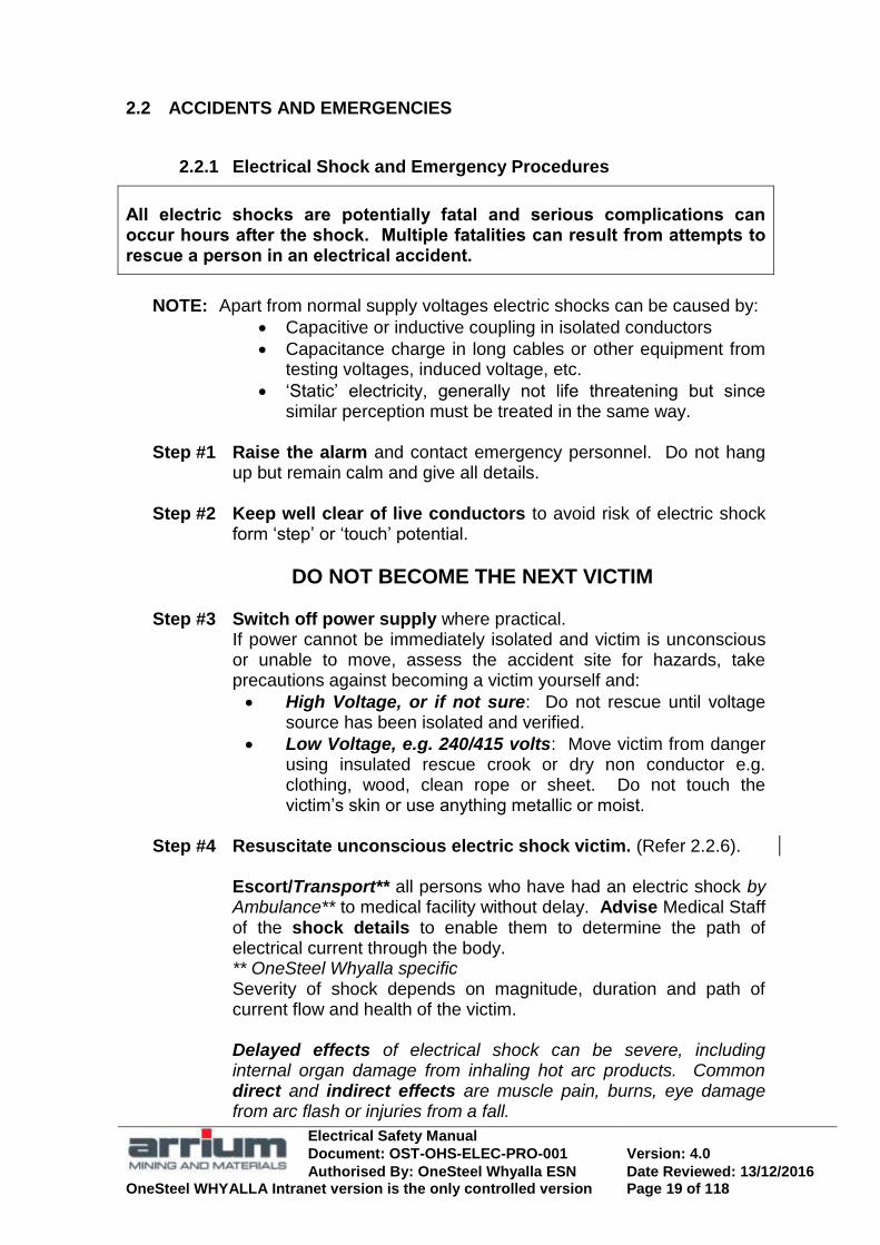
All electric shocks are potentially fatal and serious complications can occur hours after the shock. Multiple fatalities can result from attempts to rescue a person in an electrical accident.
NOTE: Apart from normal supply voltages electric shocks can be caused by:
Capacitive or inductive coupling in isolated conductors
Capacitance charge in long cables or other equipment from testing voltages, induced voltage, etc.
‗Static‘ electricity, generally not life threatening but since similar perception must be treated in the same way.
Step #1 Raise the alarm and contact emergency personnel. Do not hang up but remain calm and give all details.
Step #2 Keep well clear of live conductors to avoid risk of electric shock
form ‗step‘ or ‗touch‘ potential.
DO NOT BECOME THE NEXT VICTIM
Step #3 Switch off power supply where practical. If power cannot be immediately isolated and victim is unconscious or unable to move, assess the accident site for hazards, take precautions against becoming a victim yourself and:
High Voltage, or if not sure: Do not rescue until voltage source has been isolated and verified.
Low Voltage, e.g. 240/415 volts: Move victim from danger using insulated rescue crook or dry non conductor e.g. clothing, wood, clean rope or sheet. Do not touch the victim‘s skin or use anything metallic or moist.
Step #4 Resuscitate unconscious electric shock victim. (Refer 2.2.6).
Escort/Transport** all persons who have had an electric shock by Ambulance** to medical facility without delay. Advise Medical Staff of the shock details to enable them to determine the path of electrical current through the body. ** OneSteel Whyalla specific Severity of shock depends on magnitude, duration and path of current flow and health of the victim. Delayed effects of electrical shock can be severe, including internal organ damage from inhaling hot arc products. Common direct and indirect effects are muscle pain, burns, eye damage from arc flash or injuries from a fall.

Electrical Safety Manual
Document: OST-OHS-ELEC-PRO-001 Version: 4.0
Authorised By: OneSteel Whyalla ESN Date Reviewed: 13/12/2016 OneSteel WHYALLA Intranet version is the only controlled version Page 20 of 118
Make safe the installation causing the electric shock but do not interfere with it unnecessarily as to prevent a proper investigation of the accident. Report electric shock as soon as practical to OneSteel supervision.
Step #5 Stay in the machine (vehicle, excavator, crane, etc) if it contacts live conductors to avoid risk of electric shock. Move machine clear if possible, to break contact with the live conductor.
If necessary to leave the machine, (e.g., in case of fire), jump clear, landing with feet together and do not touch the machine. To leave a hazard site jump or take short ‗shuffle‘ steps.
Step #6 Fight Low Voltage electric fires in the early stage with hand extinguishers if practical and safe to do so. Carbon Dioxide for small electrical or Dry Chemical powder for larger fires. Otherwise keep well clear of the fire in electrical switchrooms or substations to avoid hazard from burning oil, inhalation of toxic fumes from burning cables and electric shock. Keep others clear until trained and authorised personnel arrive. Do not fight fires on HV equipment. Report the fire and wait. Do not enter a switchroom if the alarm from automatic fire protection systems is activated until the All Clear is given by Emergency Services. Audible and visual evacuation alarms are activated prior to discharge of automatic fire protection systems. Contact the Emergency Personnel with details unless you know they have been contacted.

Electrical Safety Manual
Document: OST-OHS-ELEC-PRO-001 Version: 4.0
Authorised By: OneSteel Whyalla ESN Date Reviewed: 13/12/2016 OneSteel WHYALLA Intranet version is the only controlled version Page 21 of 118
2.2.2 Arc Fault Injuries and Damage
Electrocution is an obvious risk from contact with live electrical conductors but injuries / damage through arc fault are common and often serious.
Injuries from arc fault are likely to be injuries that you will carry for the rest of your life.
Arc Blast is the pressure wave from the explosion associated with the arcing.
This could cause permanent hearing damage or injuries from flying shrapnel or burning oil.
Inhalation of hot gases or arc products may cause internal organ damage.
Medical treatment must include assessment of internal effects.
Arc Fault burns are radiation burns from the intense heat of an electric arc. These burns may be very serious and sometimes fatal. This hazard is probably not thought about as often as it should be.
Electric Arcs associated with high energy faults may generate extremely
high temperatures around 20,000 C at the arc root and cause fatal burns up to about 1.5 metres and major burns at 3 metres, depending on the available energy. The ferocity of an electric arc is such that metal vapour
and molten metal with temperatures well in excess of 1000 C shower the immediate vicinity. At these elevated temperatures clothing ignites instantly and the molten metal droplets cause spot burns.
High Energy Sources of Arc Faults High-energy electrical equipment, which has experienced a limited fault or flashover. May be as a result of misadventure or insufficient design margin in circuit interrupters or interrupters which are not maintained properly. Some high-energy sources are:
LV switchboards and motor control centres,
Power section of thyristor converter, rectifiers and large inverters.
All HV switchgear, cables, transformers, reactors, capacitors and motors.

Electrical Safety Manual
Document: OST-OHS-ELEC-PRO-001 Version: 4.0
Authorised By: OneSteel Whyalla ESN Date Reviewed: 13/12/2016 OneSteel WHYALLA Intranet version is the only controlled version Page 22 of 118
Safe distance from and protective equipment for arc faults Switching or electrical work with risk of arcing fault should be done with long sleeves flame resistant shirt buttoned at the neck, face shield and non-flammable gloves in addition to the basic PPE. More protection is afforded by multiple layers of cotton or wool clothing (i.e. singlets, tee shirt or jackets)
Minimise the risk of an arc fault Minimise the risk of injury from arc fault by:
Recognise the increased risk with open flatback panels. Understand all the sources of electrical energy to the equipment. Isolate all supplies before you work and TEST BEFORE YOU
TOUCH. Wear appropriate PPE. Before re-energisation, check the work area and the bus bar
systems for misplaced tools or debris. Avoid standing in front of or loitering near live high-energy
equipment.
2.2.3 Reporting Incidents / Accidents
All incidents, in particular electric shocks, shall be reported to the supervisor and an investigation carried out. The investigation is a vital part of OneSteel‘s WHS Policy to learn from the incident and make policy changes to ensure no reoccurrence. For all electric shocks the plant manager is responsible for reporting and investigation of the accident (both internal and as required by state legislation). Refer to Site Specific Information in Section 3.
2.2.4 Breathing Apparatus
Where personnel are required to use breathing apparatus they shall be trained in and authorised for its use. Breathing apparatus may be required for rescue in confined spaces and hazard zones. In addition fires involving electrical equipment release toxic fumes from burning cables and hence emergency rescue or restoration of critical supplies may also require the use of breathing apparatus. Individual plants should have procedures and / or work instructions to cover the operation and use of currently installed apparatus. You should be familiar with Breathing Apparatus locations in the areas you work. They are identified by a green and white safety sign.

Electrical Safety Manual
Document: OST-OHS-ELEC-PRO-001 Version: 4.0
Authorised By: OneSteel Whyalla ESN Date Reviewed: 13/12/2016 OneSteel WHYALLA Intranet version is the only controlled version Page 23 of 118
2.2.5 Emergency Procedures
#1. Raise the alarm and contact emergency personnel.
do not hang up.
remain calm.
give all details.
#2. Keep well clear of live conductors DO NOT BECOME THE NEXT VICTIM
#3. Switch off the power supply if practical.
If the power cannot be isolated assess the site for hazards:
if the voltage is High voltage or if not sure, do not attempt rescue until the power has been isolated and verified.
if you are sure the voltage is Low voltage (e.g. 240 or 415 volt), take precautions against becoming a victim yourself and move victim from danger using insulating gloves and rescue stick from an LV rescue kit (in switchroom). If no rescue kit available use dry non-conducting material. Do not touch the victims‟ skin or use anything metallic or moist.
#4. Resuscitate unconscious electric shock victim. (refer 1.2.6).
Escort/Transport* all persons who have had an electric
shock by Ambulance* to medical facility without delay.
* OneSteel Whyalla specific
#5. Stay in the machine (vehicle, excavator, crane etc) if it contacts live
conductors.
move the machine clear if possible to break contact with the live conductors.
if necessary to leave machine, jump clear landing with feet together and do not touch the machine.
to leave a hazard site jump or take short ‗shuffle‘ steps.
#6. Fight LV electrical fires in the early stage with hand extinguishers
(carbon dioxide or powder) if practical and safe, otherwise keep well clear
of fire in electrical switchrooms or substations.
contact emergency personnel (refer #1) and give details.
obey signs and signals from automatic fire protection systems.
keep others clear until trained and authorised personnel arrive.
#7 Make safe the installation, which caused an electric shock but minimise
disturbance so that a proper investigation can be done.
#8 Report all electric shocks as soon as practical.
OFF

Electrical Safety Manual
Document: OST-OHS-ELEC-PRO-001 Version: 4.0
Authorised By: OneSteel Whyalla ESN Date Reviewed: 13/12/2016 OneSteel WHYALLA Intranet version is the only controlled version Page 24 of 118
2.2.6 Resuscitation for Electric Shock

Electrical Safety Manual
Document: OST-OHS-ELEC-PRO-001 Version: 4.0
Authorised By: OneSteel Whyalla ESN Date Reviewed: 13/12/2016 OneSteel WHYALLA Intranet version is the only controlled version Page 25 of 118
2.2.7 Effect of current through the body
The chance of death from an electric shock varies directly with body current, duration and frequency of the supply. Alternating current is several times more hazardous than direct current of the same voltage. Death is mainly caused by fibrillation of the heart ventricles
when current flows during the 10-20% vulnerable period of the heart cycle.
For a given path through the human body, the danger depends mainly on the magnitude and duration of the current flow, which is dependent on the voltage of the source and the impedance of the body for that path. The total impedance for a current path hand-to-hand or hand to foot varies widely and at 220 volts is less than 1,000 ohms for 5% of the population, 1,350 for 50% and 2,125 for 95%. (Note that wet conditions can lower this considerably).
Effects of Alternating currents 15 Hz to 100 Hz and Direct current
Ventricular fibrillation, when the heart ‗flutters‘ and does not pump, is the main cause of fatal accidents in this range of AC frequencies. (2:1). Fatal accidents with DC occur only under unfavourable conditions, e.g. in mines, partly due to its higher let-go threshold. The main differences in AC and DC effects are that the stimulation of the heart is linked to changes in the current when making and breaking. DC requires 2 to 4 times AC flow for the same effect (3:1) although DC is more likely to cause burns.
Threshold of perception: About 0.5mA AC, 2mA DC.
Threshold of let-go: About 10mA AC, 300mA DC.
Threshold of ventricular fibrillation depends on:
the physiology of the person;
whether current flow occurs in the 10-20% vulnerable period of the heart cycle; and
whether current flow extends beyond one cardiac cycle. (Fibrillation is much more likely in this case).
A 10mA (type I) or 30mA (type II) rated RCD complying with AS3190 switches typically within about 20ms and for a ―typical‖ 240 volt hand to foot electric shock current flow at 1,000 ohms body resistance will fall within zone 2 “usually no harmful physiological effects”. This would cause approximately 240mA current for 20ms as illustrated on the graph at 1.2.8.

Electrical Safety Manual
Document: OST-OHS-ELEC-PRO-001 Version: 4.0
Authorised By: OneSteel Whyalla ESN Date Reviewed: 13/12/2016 OneSteel WHYALLA Intranet version is the only controlled version Page 26 of 118
2.2.8 Time/current zones of effects of ac currents through the human body
Zones of physiological effects:
1. Usually no reaction effects (perception threshold 0.5mA).
2. Usually no harmful physiological effects.
3. Usually no organic damage.
Likelihood of muscular contractions, difficulty in breathing (at extended time) and reversible disturbances in the heart.
4. In addition to the effects of zone 3, the probability of ventricular fibrillation increases with magnitude and time, eg curve c2 5%, curve c3 50%.
Cardiac arrest, breathing arrest and heavy burns may occur increasingly beyond c3.
c1 c3 c2 b a Time ms
Current milliamps
Current and duration for typical 240V electric shock with RCD protection from Type I (10mA) and II (30mA) switching at 20ms. 240V @ 1000 ohms = 240mA
50
500
200
100
20
10
10 000 5 000 2 000 1 000 0.1 500 200 100 50 20 10 5 2 1 0.5 0.2
10 000
5 000
2 000
1 000
4 Increased Ventricular fibrillation
3 Usually no
organic damage
2 Usually no
harmful effects
1 Usually no reaction effects
30 mA RCD
10 mA RCD

Electrical Safety Manual
Document: OST-OHS-ELEC-PRO-001 Version: 4.0
Authorised By: OneSteel Whyalla ESN Date Reviewed: 13/12/2016 OneSteel WHYALLA Intranet version is the only controlled version Page 27 of 118
2.3 TRAINING AND SUPERVISING PERSONNEL
2.3.1 Mandatory Training for Electrical Personnel
Resuscitation Training
All Electrical personnel, and others working where there is a risk of contact with live exposed conductors, shall undertake resuscitation and LV rescue training regularly.
For OneSteel electrical departments, resuscitation and LV rescue training at yearly intervals shall be the minimum. (note; time period is depent on state legislative requirements). The importance of resuscitation principles also applies to the home and other emergency situations. Actively encourage other employees and family members to undertake resuscitation training.
2.3.2 Electrical Apprentices & Cadets
Guidelines for Induction of Electrical Apprentices & Cadets Note: the term apprentice used in this document should be treated as a generic term that including electrical apprentices and electrotechnology cadets.
On initial engagement, before being allocated to a OneSteel department, Electrical Apprentices (also Engineering vocation students and recently graduated Engineers) shall be inducted, trained in and demonstrate competence and understanding in OneSteel Electrical Safety policies specified in this Manual.
Understanding in at least the following is recommended:
1) General Plant Safety / Induction and Training.
2) Resuscitation.
3) Incident / accident reporting.
4) Authority to Work Permits, and safety procedures such as Risk Assessment checklists and Hazard Analysis.
5) Isolation for Personal Protection regulations.
„Test before Touch‟ principles and their application for the respective site.
Test for competence required.
6) Work near live exposed conductors, safe working distances.
7) Safe electrical test and measurement techniques.
8) Electrical protection devices including RCD‟s.
9) Basic High Voltage

Electrical Safety Manual
Document: OST-OHS-ELEC-PRO-001 Version: 4.0
Authorised By: OneSteel Whyalla ESN Date Reviewed: 13/12/2016 OneSteel WHYALLA Intranet version is the only controlled version Page 28 of 118
10) Typical OneSteel installations and their hazards.
11) Ability to read and understand wiring and schematic / circuit diagrams.
12) Understand and practice the OneSteel Electrical Fundamental Rules.
Upon allocation to a OneSteel Department, the Supervisor shall ensure, before any work is assigned, that:
1) An area induction is undertaken; and
2) An experienced* Electrical Engineer or area Electrical Supervisor conducts an electrical site induction demonstrating required procedures and know hazards.
* At least 3 years experience in that area or 4 years general plant experience.
The Supervisor shall maintain a record of these inductions.
Supervising Electrical Apprentices
To prevent danger to life and property, all electrical work shall be effectively supervised, unless the worker is licensed to do the work without supervision. Apprentices should only be assigned to departments who assign an experienced tradesperson(s) to be his / her mentor. Departments should have a nominated, qualified electrical supervisor responsible to supervise and mentor apprentices. The supervisor is to maintain the apprentices logbook while in the department.
An apprentice must always be aware of both their general supervisor and their electrical supervisor for the job on hand. No work is to be carried out on ―live‖ electrical conductors by any person (refer this manual section 2.6). Electrotechnology Cadets and Graduates may have theoretical knowledge, but lack some general practical electrical experience. Thus the electrical supervisor would need to take this into account in determining competency. Provided the electrical supervisor considers the apprentice to be competent in the work be done, including knowledge of the hazards, safety procedures and the use of appropriate safeguards, the electrical supervisor may engage an electrical apprentice as follows:
Electrical Safety Manual
Document: OST-OHS-ELEC-PRO-001 Version: 4.0
Authorised By: OneSteel Whyalla ESN Date Reviewed: 13/12/2016 OneSteel WHYALLA Intranet version is the only controlled version Page 29 of 118
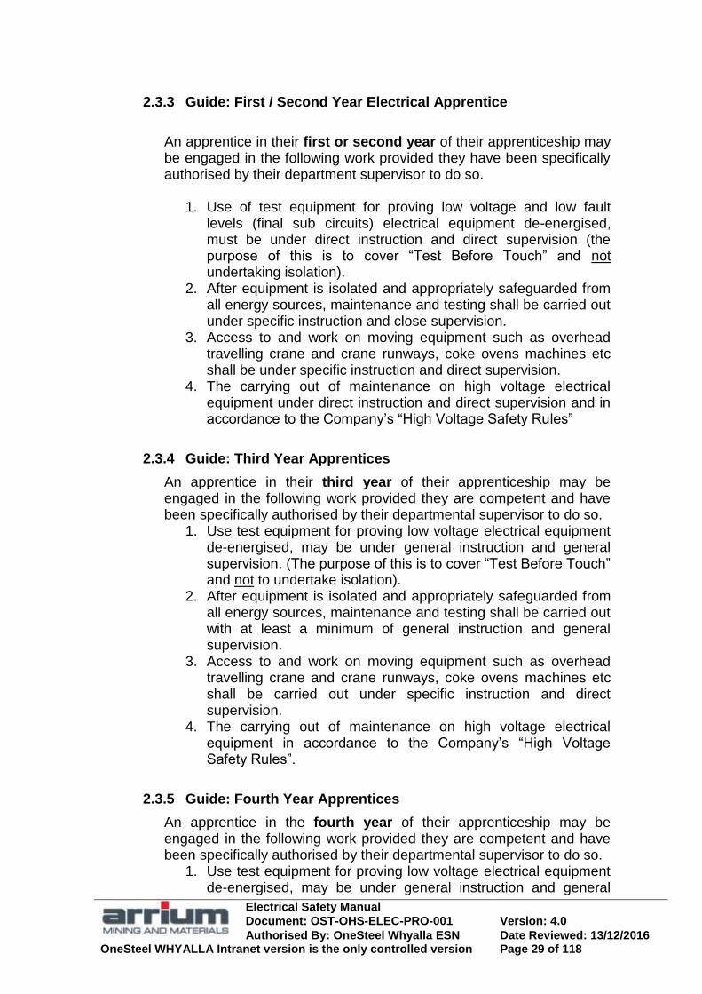
2.3.3 Guide: First / Second Year Electrical Apprentice
An apprentice in their first or second year of their apprenticeship may be engaged in the following work provided they have been specifically authorised by their department supervisor to do so.
1. Use of test equipment for proving low voltage and low fault levels (final sub circuits) electrical equipment de-energised, must be under direct instruction and direct supervision (the purpose of this is to cover ―Test Before Touch‖ and not undertaking isolation).
2. After equipment is isolated and appropriately safeguarded from all energy sources, maintenance and testing shall be carried out under specific instruction and close supervision.
3. Access to and work on moving equipment such as overhead travelling crane and crane runways, coke ovens machines etc shall be under specific instruction and direct supervision.
4. The carrying out of maintenance on high voltage electrical equipment under direct instruction and direct supervision and in accordance to the Company‘s ―High Voltage Safety Rules‖
2.3.4 Guide: Third Year Apprentices
An apprentice in their third year of their apprenticeship may be engaged in the following work provided they are competent and have been specifically authorised by their departmental supervisor to do so.
1. Use test equipment for proving low voltage electrical equipment de-energised, may be under general instruction and general supervision. (The purpose of this is to cover ―Test Before Touch‖ and not to undertake isolation).
2. After equipment is isolated and appropriately safeguarded from all energy sources, maintenance and testing shall be carried out with at least a minimum of general instruction and general supervision.
3. Access to and work on moving equipment such as overhead travelling crane and crane runways, coke ovens machines etc shall be carried out under specific instruction and direct supervision.
4. The carrying out of maintenance on high voltage electrical equipment in accordance to the Company‘s ―High Voltage Safety Rules‖.
2.3.5 Guide: Fourth Year Apprentices
An apprentice in the fourth year of their apprenticeship may be engaged in the following work provided they are competent and have been specifically authorised by their departmental supervisor to do so.
1. Use test equipment for proving low voltage electrical equipment de-energised, may be under general instruction and general
Electrical Safety Manual
Document: OST-OHS-ELEC-PRO-001 Version: 4.0
Authorised By: OneSteel Whyalla ESN Date Reviewed: 13/12/2016 OneSteel WHYALLA Intranet version is the only controlled version Page 30 of 118
supervision. (The purpose of this is to cover ―Test Before Touch‖ and not to undertake isolation).
2. After equipment is isolated and appropriately safeguarded from all energy sources, maintenance and testing shall be carried out with at least a minimum of general instruction and general supervision.
3. Access to and work on moving equipment such as overhead travelling crane and crane runways, coke ovens machines etc may be carried out under general instruction and general supervision.
4. The carrying out of maintenance on high voltage electrical equipment in accordance to the Company‘s ―High Voltage Safety Rules‖.
5. Fault finding and testing on low voltage equipment may be carried out under specific instructions and direct supervision until accredited as competent, at which time this may become specific instruction and general supervision.
6. Isolation is to be in accordance with business unit Isolation Regulations and may be carried out under specific instruction and direct supervision until accredited competent, at which time this may become specific instruction and general supervision.
2.3.6 Limitation on Overtime, Shiftwork and Strikes for Apprentices
First year apprentices should not be required to work overtime unless they are willing to do so. Overtime must NOT prevent their authorised attendance at TAFE/University.
Apprentices should NOT be permitted to work the night shift prior to, or afternoon shift following, authorised day attendance at TAFE/University, unless the shift is an emergency overtime shift and they are specifically required to do so.
Unless they are willing to do so, apprentices should not be required to work more than two overtime shifts in one week or three in one pay fortnight.
In case of strike, apprentices must receive specific instructions and work under the close supervision of an electrical supervisor.
2.3.7 Guidelines for Apprentices to Tradesperson ratio
OneSteel policy on apprentices to tradesperson ratio in normal plant work environment is one tradesperson to one apprentice. If the task being undertaken is of low risk both to individual safety and plant operational security, the apprentices have been assessed to be competent in undertaking the task set and the apprentices are at least 3 year into their apprenticeship one tradesperson could (but not preferred) supervise at maximum two apprentices.
In a workshop environment where work is undertaken on non-live equipment a single tradesperson could supervise up to a maximum of 5 apprentices provided the work being undertaken has been assessed as low risk to individual safety.

Electrical Safety Manual
Document: OST-OHS-ELEC-PRO-001 Version: 4.0
Authorised By: OneSteel Whyalla ESN Date Reviewed: 13/12/2016 OneSteel WHYALLA Intranet version is the only controlled version Page 31 of 118
2.3.8 Electrical Apprentices & Cadets – Summary Table
1st & 2nd Year 3rd Year 4th Year Authorisations Departmental
supervisor Departmental supervisor to ensure competent*
Departmental supervisor to ensure competent*
Testing low voltage to prove de-energised
Direct instruction** Direct supervision**
General instruction General supervision
General instruction General supervision
Maintenance & testing after isolating & safeguarding
Specific instruction Close supervision
General instruction General supervision
General instruction General supervision
Access to and work on moving equipment
Specific instruction Direct supervision
Specific instruction Direct supervision
General instruction General supervision
Maintenance on High voltage equipment
Follow High Voltage Safety Rules & Direct instruction Direct supervision
Follow High Voltage Safety Rules & Direct instruction Direct supervision
Follow High Voltage Safety Rules & Direct instruction Direct supervision
Testing & fault finding on energised equipment
Not performed Not performed Specific instruction Direct supervision
Isolation level 2 Not performed Not performed Specific instruction Direct supervision
Direct Supervision – the apprentice remains in the personal company (i.e. within ready sight and hearing) of the electrical supervisor. Close supervision – the apprentice performs work on their own but is checked by the electrical supervisor at intervals appropriate to the requirements of the task and the hazards present in their environment but no less than per hour. General supervision – the apprentice works on their own job but is checked by the electrical supervisor at intervals appropriate to the requirements of the task and the hazards present in their environment. Direct instructions – those instructions that specify the work to be performed in detailed steps each of which is checked before the apprentice continues to the next step. Specific instructions - those instructions that specify the actual work to be performed steps by step together with an explanation of any critical points or hazards. Understanding of the instructions is confirmed by a verbal check. General instructions - those instructions that specify the actual work to be performed but do not detail any particular method of performing tasks to complete the work. *NOTE - Work as specified in the table may be carried out provided the apprentice is competent in such work and they have been authorised by their departmental supervisor to carry out the work. **NOTE – Low Fault level equipment (final sub circuits)
Electrical Safety Manual
Document: OST-OHS-ELEC-PRO-001 Version: 4.0
Authorised By: OneSteel Whyalla ESN Date Reviewed: 13/12/2016 OneSteel WHYALLA Intranet version is the only controlled version Page 32 of 118
2.3.9 Guide to achieving electrical competency
1) Comply with all applicable laws, regulations and standards.
Maintain a copy of all relevant laws, regulations and standards.
Each electrical person shall have ready access to copies.
The list is to be reviewed regularly.
2) Employees trained to the required level of competency.
All electrical trades personnel have accredited electrical workers registration after completing their trades‟ course or commencing employment.
Electrical Technicians and Engineers have appropriate training for the work they are required to do.
Training session or refresher at least every 2 years for all employees required working near live electrical conductors.
3) Periodically train electrical employees for understanding of the regulatory requirements and standards, 2 yearly training periods recommended. Recommended that employees are also periodically assessed on their understanding of standards, statutory regulations and relevant company policies and best practices.
Understanding of the aspects of statutory regulations, AS3000 and OneSteel policies affecting all employees required working near live electrical conductors.
Refresher on important aspects of regulations and standards and recent changes.
Refresher on important site-specific electrical policies and best practices and recent changes.
Provide record of continuous electrical safety training.
Ensure all electrical employees are aware of their responsibilities.
4) Develop and maintain manuals & handbooks on electrical safe working practices.
Use as basis for the training/assessment in guideline 3 above.
Be reviewed regularly.
Readily accessible to all electrical employees.
Contain information such as:
Statutory laws, regulations, standards, and site-specific policies and best practices.
Pertinent technical data.
Safety information and procedures. e.g. Emergency phone numbers, CPR instructions, site specific WHS policies, emergency procedures.
Electrical safety „best practices‟ from experience.
5) Communicate electrical safety information to all electrical employees regularly.
Regular communications, specifically on electrical safety issues to Electricians, Technicians and Electrical Engineers, e.g. by electrical safety bulletin or specific electrical safety meeting.
6) Utilise contractors and consultants with equivalent or better basic electrical safety competency as required for OneSteel electrical employees.
Contractors and consultants are the responsibility of OneSteel.
They will be required to show that they have at least the basic level of electrical safety competency for the task as OneSteel employees.

Electrical Safety Manual
Document: OST-OHS-ELEC-PRO-001 Version: 4.0
Authorised By: OneSteel Whyalla ESN Date Reviewed: 13/12/2016 OneSteel WHYALLA Intranet version is the only controlled version Page 33 of 118
2.3.10 Responsibilities for the Provision of Training for Apprentices and Cadets
Supervisor Provide each apprentice/cadet with:
A general area induction
A specific area induction appropriate for their trade discipline that identifies procedures and hazards.
Supervision and training by a competent tradesperson to ensure their health and safety at work.
Assistance in the performance of any task not previously undertaken.
Appropriate supervision until each apprentice is competent to undertake each task without causing risk to themselves or others.
On-the-job training opportunities to develop knowledge and skills in competency units associated with each apprentices training plan.
For each apprentice/cadet assess:
The amount of assistance required according to the nature and level of risk(s) of each:
Task.
Level of experience
Level of competence Provide information:
Safety information is communicated to apprentices regularly.
Proper information, instruction and training to each apprentice before they undertake a task.
Appropriate manuals and handbooks on departmental trades safe working practices are developed and maintained.
Training management:
All training identified as being required for apprentice/cadet in their department/area is completed in a timely manner.
apprentice/cadet‘s must undertake training for understanding of regulatory requirements and standards including refresher training as necessary.
Departmental assessments are completed at least quarterly and discussed with each apprentice/cadet.
Profiling sheets and/or logbooks are kept up to date and maintained in good order by each apprentice/cadet.
Ensure that training records are maintained. On completion of their training:
Confirm that each apprentice/cadet is competent when contacted by the R.T.O. and have appropriate evidence if disputing any apprentice‘s/cadet‘s competence.
Electrical Safety Manual
Document: OST-OHS-ELEC-PRO-001 Version: 4.0
Authorised By: OneSteel Whyalla ESN Date Reviewed: 13/12/2016 OneSteel WHYALLA Intranet version is the only controlled version Page 34 of 118
Tradesperson Provide adequate supervision
Until the apprentice is competent to undertake the task without causing risk to themselves or others.
Assist the apprentice/cadet, as required, in the performance of any task not previously undertaken.
Training:
Provide proper information, instruction and training before the apprentice/cadet undertakes a task in competency units associated with each apprentices training plan.
Apply training methods suitable to the task. (Explain, Demonstrate, Simulate)
Provide feedback to the apprentice/cadet throughout the training process. Assessment:
Report on the apprentice‘s/cadet‘s progress including assisting with the completion of departmental assessments.
Ensure that apprentice/cadet profiling sheets and/or logbooks are kept up to date and maintained in good order by each apprentice.
Sign the apprentices profiling sheets and/or logbooks as required.

Electrical Safety Manual
Document: OST-OHS-ELEC-PRO-001 Version: 4.0
Authorised By: OneSteel Whyalla ESN Date Reviewed: 13/12/2016 OneSteel WHYALLA Intranet version is the only controlled version Page 35 of 118
2.4 PREPARING FOR ELECTRICAL WORK
2.4.1 Electrical Work General
All electrical installation, alterations and demolition work shall comply with National and State statutory regulations and OneSteel standards as a minimum. OneSteel electrical work requirements are set out in this manual. Hazard identification, risk assessment and risk control are a necessary (and mandatory) part of the employer and employees responsibilities.
Electrical Licensing
Only appropriately licensed electricians shall do electrical work. The definition of appropriately licensed electrician shall be according to the terms of their issued licence. The licence number and full description, including any restrictions, shall be submitted to OneSteel by the contractor prior to working on OneSteel site.
Authority to Work
Before any site work is done all electrical workers shall be instructed in the relevant OneSteel Induction training systems including the Authority to Work (ATW) / Safe System of Work (SSOW), Work Safety Permit (WSP) systems and any other pre start of work system that ensures that hazard assessment of work to be undertaken and the environment in which it is to be undertaken is reviewed/undertaken. It shall be used for all installations, alteration and demolition work.
Authority of the Electrical Supervisor
The electrical supervisors in each area are aware of the electrical and process hazards and are responsible for electrical activities in their areas All non-plant resident personnel (Project Controllers, Contractors, visitors or others) undertaking electrically related activities shall report their intended presence to the electrical supervisor of that plant. This enables appropriate plant inductions and Authority to Work (ATW) / Safe System of Work (SSOW), WSP, etc permits to be put in place. Delegation of any of these responsibilities is at the discretion of the Electrical Supervisor with the clear understanding of his / her overall responsibility.
2.4.2 Plant Area Inductions
Prior to undertaking permanent work in a plant area, electrical personnel shall do the general plant induction followed by a Plant area electrical induction conducted by the Electrical Supervisor or authorised person.

Electrical Safety Manual
Document: OST-OHS-ELEC-PRO-001 Version: 4.0
Authorised By: OneSteel Whyalla ESN Date Reviewed: 13/12/2016 OneSteel WHYALLA Intranet version is the only controlled version Page 36 of 118
The electrical induction details electrical hazards in an area plus the precautions, procedures and protective equipment required to undertake specific tasks. All OneSteel and contracting personnel, including Project Controllers, shall ensure that the Electrical Supervisor is aware of their presence on the plant and that an Authority to Work (ATW) / Safe System of Work (SSOW), WSP, etc permit or service agreement covers their activities.
2.4.3 Planning an Installation
Electrical Installations that are not designed to protect against over voltage, over current and adverse environments may result in electric shock, serious arc burns or blast injury to people or damage to property.
Unsatisfactory installations result when work is undertaken without proper scope of work or reference to relevant Australian Standards and OneSteel policies.
Planning for supply, installation or alteration of electrical equipment and all contracts, which involve electrical work shall comply with:
Business Unit Electrical Equipment Supply and Installation Manual. All equipment and its installation shall be Fit for Purpose; This Electrical Safety Manual and The Standards and Regulations nominated in the manuals Modification control documentation.
Planners and Project Controllers of all projects with electrical design, supply or installation shall be fully conversant with the above electrical requirements or direct the work to others with the required knowledge. Disciplinary action will be taken for Planners, Project Controllers or Electrical Contractors planning or doing unsatisfactory work.
2.4.4 Commencing Work
Have safety and rescue equipment on hand at the work site. Erect insulating screens or isolating barriers before starting work.
2.4.5 Inspecting, testing and Compliance Certificate (CoC, CCEW)
Incorrect installation or modification can create conditions, which result in electric shock or arc blast and flash burns. Inspection of work before connection is vital.
Inspecting and testing Electrical Work

Electrical Safety Manual
Document: OST-OHS-ELEC-PRO-001 Version: 4.0
Authorised By: OneSteel Whyalla ESN Date Reviewed: 13/12/2016 OneSteel WHYALLA Intranet version is the only controlled version Page 37 of 118
Electrical work shall be inspected / tested by the contractor before putting into service to ensure the installation is „Fit for Purpose‟ and complies with OneSteel and statutory requirements. The Contractor shall correct any non-compliance.
„Certificate of Compliance CoC” and “Certificate of Compliance Electrical Work” A Compliance Certificate (Certificate of Compliance CoC in SA and Certificate of Compliance Electrical Work CCEW in NSW) form shall be accurately completed when fixed wiring is disconnected / reconnected. Compliance to your state legislative requirements shall be met. Information to include detail description of work undertaken (work undertaken clearly identified), measured test results, e.g. earthing / insulation resistance, fault loop impedance, etc and any other legislative requirements and signed by an appropriately licensed electrical worker. Copies are to be forwarded to the area Electrical Supervisor and the Electrical Inspector Officer (if such position exists in the business unit). The Electrical Supervisor shall ensure that CCEW/CoC forms are used by their electrical personnel for all work requiring their use as defined in state legislation. The Electrical Worker shall ensure they complete CCEW/CoC form for all work requiring their completion. A copy of all CoC/CCEW shall be retained for a period of 5 years or as defined in states legislation. The Electrical Supervisor shall ensure that the earthing system resistance value is maintained over time.
2.4.6 Policies, Procedures, Work Instructions & Reference List
OneSteel policies detailed in this document and other Procedures, Manuals or Work Instructions (refer to Site Specific Information in Section 3) shall be followed where applicable to the work being carried out. The policies commonly used are listed below along with Australian Standards and Regulations referenced in this document.
Note that all applicable standards are not necessarily listed below.
Australian Standards AS and AS/NZS series AS1020 Control of undersirable static electricity AS1216 Class labels for dangerous goods AS1319 Safety signs for the occupational environment AS1657 Fixed platforms, walkways, stairways and ladders AS1674.2 Safety in welding and allied processes - Electrical AS1892 Portable Ladders.

Electrical Safety Manual
Document: OST-OHS-ELEC-PRO-001 Version: 4.0
Authorised By: OneSteel Whyalla ESN Date Reviewed: 13/12/2016 OneSteel WHYALLA Intranet version is the only controlled version Page 38 of 118
AS60974.4 Arc welding equipment – Welding power sources AS2067 Sustations and high voltage installations AS2225 Insulating Gloves for electrical purposes AS2243.7 Electrical safety in laboratories AS2317 Collared Eye bolts AS60079.10 Classification of Hazardous areas AS2467 Maintenance of electrical switchgear AS2550.1 Cranes, safe use, general requirements AS2676 Secondary batteries, guide to installation and maintenance AS2790 Portable generating sets up to 25kW AS2865 Confined spaces, safe working AS2978 Insulating Mats for electrical purposes AS3000 SAA Wiring Rules AS3010.1 Electrical installation supply by generating set (internal combustion) AS3012 Electrical equipment for construction and demolition sites AS3017 Electrical installations, verification guidelines AS3019 Electrical Installations – Periodic Verification AS3100 General requirements for approval and test specifications AS3105 Portable multi outlet devices AS3160 Approval and test specification-hand held portable electric tools AS61008.1 Residual Current Circuit Breakers (RCCB‘s) AS3190 Approval and test specification-Residual current devices AS3191 Electric flexible cord AS3199 Cord extension sets AS3350.1 Safety of household & similar electrical appliances General
requirements AS61439.4 LV Assemblies for Construction Sites (ACS) AS3760 In service inspection and testing of Electrical equipment AS3820 Essential safety requirement for LV electrical equipment AS3859 The effects of current through the human body AS3947.5.1 Electromechanical control circuit devices AS4202 Insulating covers for electrical purposes AS4576 Guidelines for Scaffolding AS4836 Safe working for LV electrical installations AS61241.3 Classification of hazardous combust dust areas
Electrical Safety Manual
Document: OST-OHS-ELEC-PRO-001 Version: 4.0
Authorised By: OneSteel Whyalla ESN Date Reviewed: 13/12/2016 OneSteel WHYALLA Intranet version is the only controlled version Page 39 of 118
2.5 ISOLATION
2.5.1 Isolation for Personal Protection (Lockout)
Protection for personal safety is by a system of isolation for personal protection using red personal locks, yellow equipment locks and green group locks. Personnel shall be trained to the appropriate level.
IT‘S YOUR LOCK! IT‘S YOUR LIFE
Personal lock: RED – Secures the isolation to protect you personally. Equipment lock: YELLOW – Secures equipment in a safe position. Group lock: GREEN – Secures equipment lock keys in Central
Isolation Board.
The isolation of sources of energy, which could pose a threat to a person‘s safety is controlled by the Responsible Manager via isolation procedures. All isolators require a lockout facility to suit at least a 6mm padlock and multi-lock device.
2.5.2 Test Before You Touch
Operating an isolator does not guarantee that the circuit is dead.
Testing for isolation needs knowledge of correct testing procedures, e.g.
Lack of indication either means the circuit is dead or the meter is defective.
A “safe” (zero or low) reading on a voltmeter could be misleading, e.g. the wrong circuit or points of equal but no zero potential are measured.
‗Test before you Touch‘ principles shall be used to prove that all power has been isolated from the circuit to be worked on. This includes testing conductors in close proximity to the work area. The effectiveness of the testing device shall be checked on a known low fault level live circuit before and after a measurement is taken. This basic principle is encapsulated in the ‗Test before you Touch‘ check list (refer 2.5.7) and a flow chart (refer 2.5.8)
Test Before You Touch Check List
1) Do I understand the job and isolation requirements? 2) Identify and control the work environment hazards.

Electrical Safety Manual
Document: OST-OHS-ELEC-PRO-001 Version: 4.0
Authorised By: OneSteel Whyalla ESN Date Reviewed: 13/12/2016 OneSteel WHYALLA Intranet version is the only controlled version Page 40 of 118
3) Have I accurately identified the equipment to be worked on? 4) Identify all relevant electrical and other energy sources then
isolate and lockout with an equipment lock(s). 5) Verify that all sources of energy are isolated or blocked by
testing and any other procedures in the Isolation Permit. 6) Apply personal lock(s).
2.5.3 Multiple and Emergency Supplies, isolating
Equipment with more than one supply presents an increased risk of electric shock. Emergency and backup power supplies may have the additional hazard of not always being present.
Be aware of possible multiple supplies including Alternate or Emergency supplies. Never assume that lack of a warning label is proof of only one supply. Before any potentially live components are touched, all relevant electrical drawings and procedures shall be studied so that all sources of power or feedback to the equipment are understood and made safe. „Test before you Touch‟ principles shall be followed before any physical contact is made with the conductors or connections.
2.5.4 Neutral Conductors, Electric Shock
If a conductor is disconnected from a neutral link it is possible for the conductor to float above earth potential if the corresponding active has not been isolated or other circuits illegally use the neutral.
‗Test before you Touch‘ principles shall be followed before any physical contact is made with any conductor removed from a termination or when conductors are separated. This shall be undertaken irrespective of the voltage reading obtained at the termination prior to cable removal, separation or disconnection.
2.5.5 Isolator operation
Operating an isolator under load or fault can result in severe injury from arc and blast particularly for isolators not designed for fault make/load break such as knife switches.
It is not well recognised that many standard isolator enclosures are not designed for arc fault containment.

Electrical Safety Manual
Document: OST-OHS-ELEC-PRO-001 Version: 4.0
Authorised By: OneSteel Whyalla ESN Date Reviewed: 13/12/2016 OneSteel WHYALLA Intranet version is the only controlled version Page 41 of 118
General Isolator operation Isolator operation shall be carried out only by authorised persons. When isolating and restoring power on open panels:
Isolating supply Open Control Switch before Main Switch
Restoring supply Close Main Switch before Control Switch
Switch status indication Switch status indication labelling must be clear and unambiguous and it is important to be familiar with the different labelling systems that are used. If unsure, contact your Supervisor before proceeding with isolation.
PPE for Isolation and Lockout operations To protect against electric shock and arc faults, appropriate PPE shall be used when operating and locking out HV and High Fault Level LV isolators and open panel knife switches.
2.5.6 Isolating Specific Equipment
Isolating Cable Distribution Networks Be aware of the possibility of long cables holding a harmful capacitive charge even after isolation of power sources.
Isolating Distribution Boards Distribution Boards shall be isolated before any electrical work is done on them.
Isolating Fuses and similar The OneSteel Personal Isolation System requires that all isolators including fuses and other devices without direct padlocking facility be adapted for padlocking. This has been achieved, e.g. by the use of insulated chain, and hence all these devices shall be padlocked as part of isolation procedures.
Isolating Equipment with Emergency Backup Power Some electrical equipment may have an emergency backup supply from a UPS, which will continue to provide power after isolation or failure of the main supply.
Isolating Light Fittings for Maintenance Ensure there is no possibility of a shock during routine maintenance including checking for possible emergency supplies and charged capacitors.
Isolating Plumbing/Air Conditioning Installations Workers with a restricted electrical licence may only operate isolation devices associated with their work (as identified on their licence).

Electrical Safety Manual
Document: OST-OHS-ELEC-PRO-001 Version: 4.0
Authorised By: OneSteel Whyalla ESN Date Reviewed: 13/12/2016 OneSteel WHYALLA Intranet version is the only controlled version Page 42 of 118
Isolating Fixed / Portable Equipment connected by a plug / socket and cord Isolation of fixed equipment such as window / wall air conditioners and wall mounted water heaters shall be similar to isolation for portable equipment as above.
For isolation for maintenance on portable and fixed equipment supplied by plug / socket outlet, the supply plug shall be withdrawn from the supply socket and remain under the control of the person doing the maintenance.
The plug must not be left where it could be put into an outlet without being noticed by the maintenance worker. Isolation by lockout requires a special locking device for the plug and should be used if the plug cannot be under the control of the maintenance worker.

Electrical Safety Manual
Document: OST-OHS-ELEC-PRO-001 Version: 4.0
Authorised By: OneSteel Whyalla ESN Date Reviewed: 13/12/2016 OneSteel WHYALLA Intranet version is the only controlled version Page 43 of 118
2.5.7 Test before you touch checklist
1. Do I understand the job & isolation requirements?
voltage levels
ATW Authority to Work
any other relevant permits
Complete testing/faultfinding SSOW/PTRA
2. Identify and control the work environment hazards
area free of tripping hazards?
damp situations?
access and egress?
clear area of unnecessary equipment and materials
safeguards to prevent hazards from moving equipment
barriers to prevent inadvertent contact with other live circuits/equipment
3. Have I accurately identified the equipment to be worked on?
refer to relevant electrical drawings
check for correct labelling
4. Identify all relevant electrical and other energy sources, including
multiple feeds to equipment, induced voltage or capacitive charge then
isolate & lockout with equipment lock/s
refer to relevant electrical drawings
refer to relevant procedures, work instructions & switching schedules
consider connections becoming live due to the operation of automatic control devices such as thermostats, float switches, PLC‘s & other interface devices
consider live connections from induced voltage or capacitive charge from testing procedures or other unexpected sources.
check for voltage on disconnected/ separated neutral conductors
5. Verify that all sources of energy are isolated or blocked
Prove the test instrument (before and after testing for isolation) Check test instrument on a known low fault level voltage source before and after test.
Test that the all power has been isolated from the circuit to be worked on Test for Isolation effectiveness, multiple supplies and feedback.
Any other verification procedure in the Isolation permit May include test for zero pressure, try normal controls, visual check of isolator contacts etc.
6. Apply personal lock/s Procedure depends on whether individual or group isolation. The circuit to be worked on should be tested at the work site before starting work.
The following Safety
policies must be strictly
observed:
1. All redundant cables to
be removed according to
Work Instruction
WI37.07.004.
2. Isolation of all
equipment before working
on according to QP29.20
and the Plant policies.
3. Inspect and test all
installations and fill out
Notification of Electrical
Work form.
ATW for Conveyor
OFF
DANGER
LOCKED
OUT
DO NOT REMOVE
OF
F V
OF
F V
OF
F V

Electrical Safety Manual
Document: OST-OHS-ELEC-PRO-001 Version: 4.0
Authorised By: OneSteel Whyalla ESN Date Reviewed: 13/12/2016 OneSteel WHYALLA Intranet version is the only controlled version Page 44 of 118
2.5.8 Test before you touch flowchart
Job
Job and isolation requirements
understood?
Identify & control work place hazards
Equipment accurately & positively
identified?
Variations for group isolation
Prove the test equipment
Circuit
dead?
Identify all supplies. Check multiple supplies. Isolate &
lock out with equipment lock
Test circuit at work site
Ask for help
OFF
DANG
ER
LOCKED
OUT
DO NOT
REMOVE
OFF V
Re-test the test equipment
OFF V
Isolation of all energy sources
verified?
DANG
ER
LOCKED
OUT
DO NOT
REMOVE
OFF V
Apply personal lock/s
See Sheet 2
The Isolation Permit may include other verification tests.
Test for induced volts see Sheet 2
Isolate
Verify
Use High Impedance (digital) meter. Check Battery condition.
Plan
Start work
Sheet 1

Electrical Safety Manual
Document: OST-OHS-ELEC-PRO-001 Version: 4.0
Authorised By: OneSteel Whyalla ESN Date Reviewed: 13/12/2016 OneSteel WHYALLA Intranet version is the only controlled version Page 45 of 118
Test before you touch flowchart
TESTING FOR INDUCED VOLTAGE
this is a sub section of the ‗Test before you Touch‘ flow chart.
it is used if the High Impedance test meter shows that voltage is present.
test with a Low Impedance meter (digital or analogue) or test lamp etc.
Warning: Always check the meter battery condition before testing and change battery if low indication.
the Low Impedance tester indication will determine whether the voltage is System (no reading) or Induced (reading).
the Low Impedance tester indication will determine whether the voltage is System (no reading) or Induced (reading).
To sheet 1
From sheet 1
Induced volts present:
check source.
earth cable; or
use insulating gloves.
System volts present. Check
Isolation
Test with
Low Impedance
meter
Circuit Dead? (0 Volts)
Sheet 2
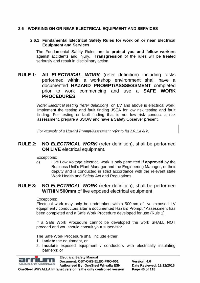
Electrical Safety Manual
Document: OST-OHS-ELEC-PRO-001 Version: 4.0
Authorised By: OneSteel Whyalla ESN Date Reviewed: 13/12/2016 OneSteel WHYALLA Intranet version is the only controlled version Page 46 of 118
2.6 WORKING ON OR NEAR ELECTRICAL EQUIPMENT AND SERVICES
2.6.1 Fundamental Electrical Safety Rules for work on or near Electrical Equipment and Services
The Fundamental Safety Rules are to protect you and fellow workers against accidents and injury. Transgression of the rules will be treated seriously and result in disciplinary action.
RULE 1: All ELECTRICAL WORK (refer definition) including tasks performed within a workshop environment shall have a documented HAZARD PROMPT/ASSSESSMENT completed prior to work commencing and use a SAFE WORK PROCEDURES.
Note: Electrical testing (refer definition) on LV and above is electrical work. Implement the testing and fault finding JSEA for low risk testing and fault finding. For testing or fault finding that is not low risk conduct a risk assessment, prepare a SSOW and have a Safety Observer present.
For example of a Hazard Prompt/Assessment refer to fig 2.6.1.a & b.
RULE 2: NO ELECTRICAL WORK (refer definition), shall be performed ON LIVE electrical equipment.
Exceptions: a) Live Low Voltage electrical work is only permitted if approved by the
Business Unit‘s Plant Manager and the Engineering Manager, or their deputy and is conducted in strict accordance with the relevent state Work Health and Safety Act and Regulations.
RULE 3: NO ELECTRICAL WORK (refer definition), shall be performed WITHIN 500mm of live exposed electrical equipment
Exceptions: Electrical work may only be undertaken within 500mm of live exposed LV equipment / conductors after a documented Hazard Prompt / Assessment has been completed and a Safe Work Procedure developed for use (Rule 1) If a Safe Work Procedure cannot be developed the work SHALL NOT proceed and you should consult your supervisor. The Safe Work Procedure shall include either: 1. Isolate the equipment, or 2. Insulate exposed equipment / conductors with electrically insulating
barrier/s; or

Electrical Safety Manual
Document: OST-OHS-ELEC-PRO-001 Version: 4.0
Authorised By: OneSteel Whyalla ESN Date Reviewed: 13/12/2016 OneSteel WHYALLA Intranet version is the only controlled version Page 47 of 118
3. Wear appropriate PPE to protect against electric shock and energy from arc blast
RULE 4: TEST BEFORE TOUCH shall be performed prior to contacting any electrical equipment.
2.6.2 Emergencies
If a situation arises that involves;
a threat to the wellbeing of a person / group of persons, and/or
The potential for loss of critical process control or stability or the risk of a significant loss of operational security or critical plant
and the risk of delay in undertaking a documented SSoW significantly increases the probability/extent of the above a mental SSoW may be undertaken and the task completed only if the mental risk assessment has deemed it safe to undertake the proposed course of action (based on the individual‘s plant/equipment knowledge and environmental conditions

Electrical Safety Manual
Document: OST-OHS-ELEC-PRO-001 Version: 4.0
Authorised By: OneSteel Whyalla ESN Date Reviewed: 13/12/2016 OneSteel WHYALLA Intranet version is the only controlled version Page 48 of 118
Figure 2.6.1.a Example of a Hazard Prompt/Assessment (side1)
EXAMPLE ONLY
Example of Whyalla’s SSoW, QP29.13
Attachment 7 (side 1)
REFER TO QP29.13
ATTACHMENT 7

Electrical Safety Manual
Document: OST-OHS-ELEC-PRO-001 Version: 4.0
Authorised By: OneSteel Whyalla ESN Date Reviewed: 13/12/2016 OneSteel WHYALLA Intranet version is the only controlled version Page 49 of 118
Figure 2.6.1.b Example of a Hazard Prompt/Assessment (side2)
EXAMPLE ONLY
Example of Whyalla’s SSoW, QP29.13
Attachment 7 (side 2) REFER TO QP29.13
ATTACHMENT 7

Electrical Safety Manual
Document: OST-OHS-ELEC-PRO-001 Version: 4.0
Authorised By: OneSteel Whyalla ESN Date Reviewed: 13/12/2016 OneSteel WHYALLA Intranet version is the only controlled version Page 50 of 118
2.6.3 Awareness of electrical equipment/services when working
Work near electrical equipment could damage it and result in electric shock or injury from the extreme energy of an arcing fault. The risk is much higher if the equipment has live exposed conductors where an electric shock can result through direct contact or an arc fault by unintentionally initiating an arc.
Some materials may unexpectedly conduct electricity, including damp clothing, gases, liquid and flames.
All workers responsibilities when working near electrical equipment All workers must be aware of electrical equipment or services where they work and make sure it is not damaged or becomes damaged by the work. If concerned about the safety of electrical equipment or services, get advice from the local electrical department. Electrical workers should use their knowledge to assist others to maximise electrical safety when using or working near electrical equipment. Access Clearance from Electrical Installations
Equipment and materials stored close to electrical installations create a fire hazard and hazards for electrical personnel, e.g. block emergency aggress.
All workers must be aware of electrical equipment or services where they work and make sure it is not damaged or becomes damaged by the work. Equipment and materials shall not be positioned in the immediate vicinity of electrical installations such as switchgear, termination panels and distribution boards
Clearance from boundaries of
electrical equipment is required for safe
operation
600 min
600 min
600 min
Electrical Safety Manual
Document: OST-OHS-ELEC-PRO-001 Version: 4.0
Authorised By: OneSteel Whyalla ESN Date Reviewed: 13/12/2016 OneSteel WHYALLA Intranet version is the only controlled version Page 51 of 118
Penetrating floors, walls and ceilings
Hand tools penetrating floors, walls or ceilings can result in unintended contact with hidden live electrical circuits and cause electric shock.
Screws, nails etc can penetrate cables and leave a shock hazard.
Any penetration of a surface shall comply with Excavation / Puncture of Surface Code of Practice and any permits required. WARNING: Cable detectors may not be able to detect cables embedded in walls and cavities in some situations.
Before work involving plant or building modification, take time to observe position of lighting switches, power points and electrical controls. Live electrical cables are usually concealed in wall cavities, in the roof, in control desks or panels, or behind cable duct covers.
Penetrations close to light switches or power points are hazardous. If in doubt, have the relevant circuits isolated and immediately report any suspected contact with cabling:
Cables usually drop from the roof space and inside the wall cavity or
Hollow structural members such as door frames may have been used
A horizontal cable route may have been used for close power points or
A blank wall plate may still have live cabling connected to it.
Cables associated with plant electrical control systems and lighting circuits requires special attention as such circuits are not protected by RCD‟s.
Cabling to socket outlets may not be protected by RCD‟s
Working on or near cables in Cable Trays or Ladders
Electric shock may result while working near cable trays or handling cables in a cable tray due to previous damage to or deterioration of the cable or the presence of live redundant cables
Work with or in the vicinity of electrical cable trays or ladders shall comply with business unit specific work instructions.

Electrical Safety Manual
Document: OST-OHS-ELEC-PRO-001 Version: 4.0
Authorised By: OneSteel Whyalla ESN Date Reviewed: 13/12/2016 OneSteel WHYALLA Intranet version is the only controlled version Page 52 of 118
Working near Underground Electrical Services
Indiscriminate excavation work can result in people being exposed to a dangerous electrical situation or disruption to electrical services. Such incidents have serious safety implications and usually result in plant delays.
All underground excavations shall comply with business unit‘s excavation/piling work instruction and have an excavation permit that has been signed off by authorised personnel as detailed in the work instruction.
Note: Warning Tape installed half way between the underground service, or service protection, and the surface.
The following processes / principles should be maintained:
Obtain an excavation permit from the appropriate clearance officers.
Complete an ATW, WSP for the excavation.
The electrical clearance officer will locate existing cables by searching documentation and using cable location equipment.
Isolate power in known cables in the excavation area when possible.
The clearance officer will physically mark the surface for excavation clearance zones.
Have a qualified electrical watcher observe during excavation where cables are or may exist.
Instruct equipment operators in emergency procedures in case of uncovering a live cable.
The trained watcher will hand dig at all critical exposure points.
Arrange for site survey and relevant documentation / drawing update.
Take photos prior to backfill and file for future reference
Backfill
LV cable in PVC conduit buried in ground
Cable buried direct in ground
Backfill
Sand free of stones Typical underground cable installations
Warning Tape

Electrical Safety Manual
Document: OST-OHS-ELEC-PRO-001 Version: 4.0
Authorised By: OneSteel Whyalla ESN Date Reviewed: 13/12/2016 OneSteel WHYALLA Intranet version is the only controlled version Page 53 of 118
Ground storage of heavy / hot products including landscaping
Storage of very heavy or hot products may damage underground cables
Before earthworks, landscaping or ground storage of very heavy or hot products are planned, the possibility of inadvertently covering and thereby causing damage to underground cables should be investigated.
2.6.4 PPE / Dress for Electrical Work
PPE / Dress for Electrical Work, General
PPE (Personal Protective Equipment) shall be used when the risk cannot be completely eliminated or controlled by Engineering and Administrative controls. When working in the vicinity of live conductors, the body, arms and legs shall be covered and appropriate personal protective Equipment (PPE) worn. Minimum PPE / Dress for Electrical Work Shall be as follows:
Safety glasses with side shields.
Lightweight leather gloves (gauntlet type to protect the wrist) wherever practical.
Safety hat, hearing and / or hand protection where required by the nature or location of the work site or as indicated by local safety signs.
Safety footwear with rubber soles.
Long sleeves and collard shirt fastened at the wrist,
made of material such as Indura Ultra Soft and offering a minimum ATPV rating of 8.7cal/cm2 or Tecasafe equivalent
with sleeve cuff openings that are designed to make it difficult to roll sleeve up
with sleeve placket openings sewn up or gusseted or fastened to prevent exposure to bare wrist
and
long trousers that cover the ankles, made of material such as Indura Ultra Soft with a minimum ATPV rating of 8.7 cal/cm2 or Tecasafe equivalent
or
overalls made from material such as Indura Ultra Soft with minimum APTV rating of 12.4cal/cm2 or Tecasafe equivalent

Electrical Safety Manual
Document: OST-OHS-ELEC-PRO-001 Version: 4.0
Authorised By: OneSteel Whyalla ESN Date Reviewed: 13/12/2016 OneSteel WHYALLA Intranet version is the only controlled version Page 54 of 118
PPE for tasks with increased risk of shock or arcing Some electrical tasks at OneSteel sites have an increased risk due to the nature and age of the plant and the presence of some uninsulated equipment.
Task example and PPE additional to minimum
Insu
latin
g G
love
s 3
Non
-fla
mm
ab
le
glo
ve
s e
.g. le
ath
er
Insu
latin
g M
at
4
Full
face
sh
ield
5
Sw
itch
ing
co
at
7
Switching LV knife or open switch <100A R M R R -
Switching LV knife or open switch >100A R M R M R
Switching LV enclosed switch >100 A - R R R R
Switching HV at breaker see 2.9 R M R M M
Lockout on live open panels 1 R M R - -
Work at rear of live open panel 2 M - M R -
Electrical testing LV control circuits M - R R -
Electrical testing high energy LV circuits M - M M R
Energised cables on tray M - - - -
Resetting open panel overload M - R R R
Other electrical work R Note 6 R - -
Non electrical work, e.g. cleaning switchrooms 2 Subject to risk assessment
R = Recommended M = Mandatory - = not required
1. To minimise non-electrical personnel need to enter electrical switchrooms isolation boards should be located outside the switchrooms where practical.
2. Non-electrical worker not permitted to work at rear of open panel, unless authorised by Electrical Supervisor.
3. Insulating gloves to AS2225 or IEC903. Minimum rating – Class O (1000V working) and ATPV 21.6 cal/cm2, . Leather over glove to be used when the insulated glove may be damaged by the task
4. Insulating mat (personal) for additional risk control for electric shock. To AS4202.
5. Approved full-face shield with balaclava: (face shield is to have no metal rim for control of arc risk and shall be OneSteel standard Uvex arc rated faceshield).
6. Insulated and arc fault rated gloves to be worn for control of shock and arc risk when testing or faultfinding on energised LV.
7. Switching coat shall be Indura Ultra Soft type and when worn over the standard electrical PPE give a minimum APTV rating of 51.5cal/cm2.

Electrical Safety Manual
Document: OST-OHS-ELEC-PRO-001 Version: 4.0
Authorised By: OneSteel Whyalla ESN Date Reviewed: 13/12/2016 OneSteel WHYALLA Intranet version is the only controlled version Page 55 of 118
PPE/Dress for electrical work

Electrical Safety Manual
Document: OST-OHS-ELEC-PRO-001 Version: 4.0
Authorised By: OneSteel Whyalla ESN Date Reviewed: 13/12/2016 OneSteel WHYALLA Intranet version is the only controlled version Page 56 of 118
Restrictions on personal adornment for Electrical Work
Metallic conductive jewellery etc increases the chance of electric shock.
Personal Metallic or conductive jewellery etc. shall not be worn. Remove finger rings, metal watches, neck chains, bracelets, earrings and keys fitted to belts etc before work. Metal framed safety glasses should be restrained against falling off while working and covered with overglasses if practical.
2.6.5 Authorisation for specific electrical work / tasks
Authorisation and task permitted
.
Please work safe.
Look after your fellow
worker too.
……………………………..
Sw
itch
ing L
V k
nif
e or
open
sw
itch
Sw
itch
ing L
V e
ncl
ose
d s
wit
ch >
100 A
Sw
itch
ing H
V a
t bre
aker
see
(2.
9)
Lock
out
on l
ive
open
pan
els
3
Work
at
rear
of
live
op
en p
anel
4,5
Ele
ctri
cal
test
ing L
V 5
Ener
gis
ed c
able
s on t
ray
Tes
ting o
n h
igh e
ner
gy
cir
cuit
s
Res
etti
ng o
pen
pan
el o
ver
load
Oth
er e
lect
rica
l w
ork
Oth
er w
ork
, e.
g. cl
eanin
g s
wit
chro
om
s
HV authorised electrical worker 1, 2
Licensed electrical worker 1, 2
Trained non electrical worker 1, 4
= Permitted, = Not permitted
1. All workers entering switchrooms must have switchroom access training
2. Licensed electrical worker (2.4.1) or experienced Electrical Engineer
3. To minimise non-electrical personnel need to enter electrical switchrooms isolation
boards should be located outside the switchrooms where practical..
4. Non-electrical worker not permitted to work at rear of open panel, unless authorised by Electrical Supervisor.
5. Electrical SSOW, Authorised testing JSEA and safety observer if required

Electrical Safety Manual
Document: OST-OHS-ELEC-PRO-001 Version: 4.0
Authorised By: OneSteel Whyalla ESN Date Reviewed: 13/12/2016 OneSteel WHYALLA Intranet version is the only controlled version Page 57 of 118
2.6.6 Work in Switchrooms
Access to switchrooms by unauthorised or untrained workers has risk of serious injury or death to the person and major disruptions to plant operations.
All plant electrical switchrooms and field panels shall be secured against unauthorised access. Switchrooms shall be locked and appropriate warning signs installed on all access doors as specified in AS 3000. Persons requiring access to switchrooms as part of work, e.g. cleaning or isolating, shall be suitable trained and authorised by responsible plant manager so they can carry out their work in safety. An untrained person may only enter a switchroom if they are accompanied by an authorised person. Policy for not loitering around high voltage or high current electrical equipment and maintaining all covers, enclosures or barriers shall be maintained.
Work in Switchrooms, General
All Access is to be authorised. A risk assessment should be done for work in switchrooms. Work in switchrooms with open panels is potentially hazardous. Avoid false alarms when doing maintenance work in switchrooms with automatic fire protection. Notify Emergency Services or the Project Controller promptly in the event of alarms and hazardous conditions.
When working in switchrooms note the locations in the room of safety related items such as:
Live exposed conductors and any barriers, screening & restricted areas;
Entrance & exits; Check that emergency exits are free and unobstructed
Telephone and other communication devices;
Fire fighting appliances;
Rescue kits, fire blankets and similar; and
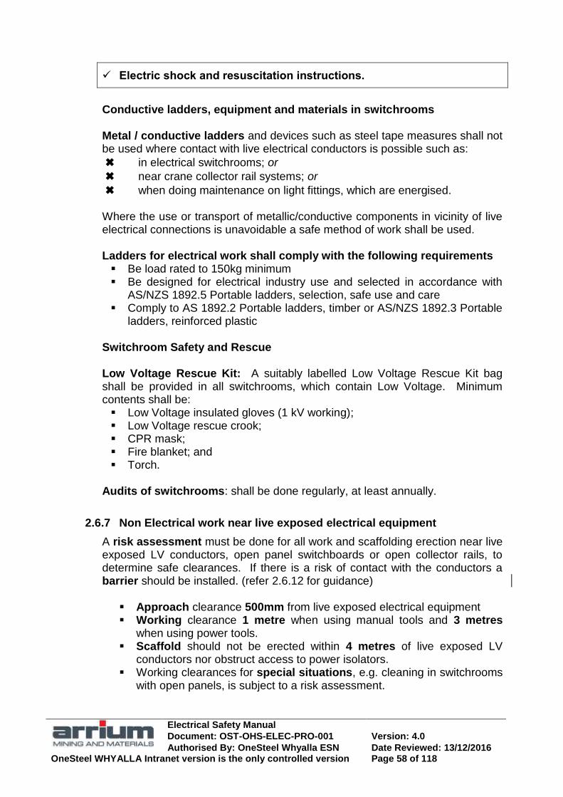
Electrical Safety Manual
Document: OST-OHS-ELEC-PRO-001 Version: 4.0
Authorised By: OneSteel Whyalla ESN Date Reviewed: 13/12/2016 OneSteel WHYALLA Intranet version is the only controlled version Page 58 of 118
Electric shock and resuscitation instructions.
Conductive ladders, equipment and materials in switchrooms
Metal / conductive ladders and devices such as steel tape measures shall not be used where contact with live electrical conductors is possible such as:
✖ in electrical switchrooms; or
✖ near crane collector rail systems; or
✖ when doing maintenance on light fittings, which are energised.
Where the use or transport of metallic/conductive components in vicinity of live electrical connections is unavoidable a safe method of work shall be used. Ladders for electrical work shall comply with the following requirements Be load rated to 150kg minimum Be designed for electrical industry use and selected in accordance with
AS/NZS 1892.5 Portable ladders, selection, safe use and care Comply to AS 1892.2 Portable ladders, timber or AS/NZS 1892.3 Portable
ladders, reinforced plastic
Switchroom Safety and Rescue Low Voltage Rescue Kit: A suitably labelled Low Voltage Rescue Kit bag shall be provided in all switchrooms, which contain Low Voltage. Minimum contents shall be: Low Voltage insulated gloves (1 kV working); Low Voltage rescue crook; CPR mask; Fire blanket; and Torch.
Audits of switchrooms: shall be done regularly, at least annually.
2.6.7 Non Electrical work near live exposed electrical equipment
A risk assessment must be done for all work and scaffolding erection near live exposed LV conductors, open panel switchboards or open collector rails, to determine safe clearances. If there is a risk of contact with the conductors a barrier should be installed. (refer 2.6.12 for guidance)
Approach clearance 500mm from live exposed electrical equipment Working clearance 1 metre when using manual tools and 3 metres
when using power tools. Scaffold should not be erected within 4 metres of live exposed LV
conductors nor obstruct access to power isolators. Working clearances for special situations, e.g. cleaning in switchrooms
with open panels, is subject to a risk assessment.

Electrical Safety Manual
Document: OST-OHS-ELEC-PRO-001 Version: 4.0
Authorised By: OneSteel Whyalla ESN Date Reviewed: 13/12/2016 OneSteel WHYALLA Intranet version is the only controlled version Page 59 of 118
2.6.8 Electrical work near live exposed electrical equipment
Qualified electrical workers shall not let any part of their body or any conducting tool or object encroach within 500mm of live exposed electrical equipment up to 1000 volts a.c., or for other voltages refer to specific state Electricity Regulations. All personnel involved in Electrical work, including the Project Controller and Electrical workers, shall be aware of and comply with the minimum safe clearances.
2.6.9 Work and storage near overhead power lines
Work near live overhead conductors presents risk to workers not trained for work near live electrical equipment; the varying position of equipment and materials; and the varying position of power lines through sag and sway.
Prior approval from the business unit High Voltage Engineer shall be obtained for all work or storage within 10 metres of an overhead power line or for work, which could breach the minimum clearances. Electrical workers shall maintain clearance for live exposed aerial conductors as specified in State Regulations (refer 2.6.13) Working clearances shall be maintained between a crane or elevating machine and its load and live conductors to ensure the safety for all workers and comply with relevant standards / regulations. A risk assessment must be done before crane work starts. Allowance must be made for sag and sway movement by wind. An observer / spotter is required when approaching the ‗No go zone‘. Materials shall not be stored closer to supporting structures and aerial conductors than specified in State Regulations Written permission for transport of high loads on OneSteel works roads is to be obtained from the business unit High Voltage Engineer, so that safe clearances form power lines can be maintained. Emergency Procedures for working near live conductors Operators of cranes / excavators etc shall be instructed in safe emergency procedures in case of contacting live conductors. Written emergency procedures should be visible to the operator.

Electrical Safety Manual
Document: OST-OHS-ELEC-PRO-001 Version: 4.0
Authorised By: OneSteel Whyalla ESN Date Reviewed: 13/12/2016 OneSteel WHYALLA Intranet version is the only controlled version Page 60 of 118
2.6.10 Work on Extra Low Voltage (ELV)
ELV circuits often cause harmful arcing if worked on live and may cause dangerous electric shock in adverse circumstances.
ELV systems shall be isolated before work unless extenuating circumstances exist. High current ELV circuits present the risk of arcing burns, dangerous electric shock in adverse circumstances and equipment damage if working live.
6V ac 15V dc
60V dc
120V dc
25V ac
50V ac Shall not be worked on live but isolated as for L.V. AS3000* requires IP20 protection for this voltage range. No exceptions. Note: Arc welding and telephone voltages fall within and above this range. Refer to 2.14 „Welding Electrical Safety‟ and AS1674.2.
Shall not be worked on live unless extenuating
circumstances exist.
Working live presents an electric shock risk for wet and large area body contact situations. Confined space, wet conditions & large area body contact (>80cm
2) are typical
increased electric shock risk situations according to AS3000* & AS3859.
Take precautions against arcing.
Working live does not present an electric shock risk. AS3000* does not require protection against direct contact for this range.
<L
V>
GUIDELINES for work on Extra Low Voltage
<<
Extr
a L
ow
Vo
ltag
e >
>
If extenuating circumstances exist and live work on ELV conductors must be performed the following shall be undertaken;
A risk assessment undertaken and documented prior to job commencement. The risk assessment shall include measures to be undertaken to control the risk of personal injury e.g. gloves, damage to plant equipment and operational outage.
Identify the circuit to be worked on including voltage levels (shall be ELV).
Measure voltage levels and confirm ELV
All fixed wiring when disconnected shall be housed in a suitable enclosure as per AS3000 1.5.11.4.
Barriers to be installed whenever working within 500mm of exposed live terminals / conductors.

Electrical Safety Manual
Document: OST-OHS-ELEC-PRO-001 Version: 4.0
Authorised By: OneSteel Whyalla ESN Date Reviewed: 13/12/2016 OneSteel WHYALLA Intranet version is the only controlled version Page 61 of 118
2.6.11 Approval for work on / near electrical equipment
All electrical work: Electrical workers only.
Hazard prompt/Safe System of Work/ assessment.
Electrical work on or within 500 mm of live exposed electrical equipment: Electrical workers only. Risk assessment/ authorised testing JSEA/ authority to work live.
ELECTRICAL EQUIPMENT AUTHORISED PERSONS
ONLY
DANGER
Access and work in switchrooms: Training/ authorisation.
High load transport: Approval from business unit HV Engineer.
Work or storage near power lines: Approval from the business unit HV Engineer.
Scaffolding or work near fixed live exposed LV conductors: Risk assessment.
Work on or near cable trays:
Business unit work instruction, (e.g. Whyalla WI37.07.001)
Penetrating surfaces: Penetration permit as per CoP and business unit work instruction
(e.g. Whyalla WI37.07.003).
Excavation, earth works, landscaping and ground storage of
heavy or hot products etc:
Excavation permit as per CoP or business unit work instruction (e.g.
Whyalla WI37.EIC.086)
Hot work: Hot work permit as per business unit work instruction
(e.g. Whyalla WI29.251)

Electrical Safety Manual
Document: OST-OHS-ELEC-PRO-001 Version: 4.0
Authorised By: OneSteel Whyalla ESN Date Reviewed: 13/12/2016 OneSteel WHYALLA Intranet version is the only controlled version Page 62 of 118
2.6.12 Work near live conductors (general)
System voltage of live exposed conductors.
500mm
Up to 1000V
1000V to 11kV
700mm *
11kV to 33kV
1.0m *
Elect work(authorised electrical worker only)
Based on State‘s Electrical Regulation (e.g. SA WHS Regs & Elec Act)
See this manual
Use PPE as per this manual 2.6.4
System voltage of live exposed conductors
Up to 1000V
1000V to 11kV
300mm
11kV to 33kV
450mm
Electrical Testing and HV Earthing (authorised electrical worker only)
Based on State‘s Electrical Regulation (e.g. SA WHS Regs & Regs Elec Act)
Use PPE as per this manual 2.6.4
CLEARANCES for work on or near electrical equipment or service
* for working clearance refer to State Electricity Reg‟s or HV Safety Rules.
Isolator access
Risk assessment (4m minimum AS4576)
Scaffolding
Manual
tools 1 m guideline
Power tools 3 m guideline 500 mm
Barrier may be required
AS4576 Scaffolding guidelines
L.V.
Non electrical work: Scaffold, manual & power tools

Electrical Safety Manual
Document: OST-OHS-ELEC-PRO-001 Version: 4.0
Authorised By: OneSteel Whyalla ESN Date Reviewed: 13/12/2016 OneSteel WHYALLA Intranet version is the only controlled version Page 63 of 118
2.6.13 Work near power lines
Safe approach, working and storage clearances for power lines up to 33kV
Working clearance from cranes/ elevating machines
(Permit required from HV Group Engineer for all work within 6.4m of live conductors)
3.0 m 6.4
m
Storage clearance for above 1kV up to 33kV
Storage clearance for up to 1kV 5.0 m
10.0 m
Approach clearance for electrical work and clearance for storage of materials (Permit required from HV Group Engineer for all storage within 10m of live conductors)
10.0 m
5.0 m
Safe approach clearance from live exposed conductors
for electrical work;
- up to 1kV: 500mm - above 1kV up to 11kV: 700 mm - above 11kV up to 33kV: 1.0 m See 1.6.9 for information source.
6.4 m
3.0 m 3.0 m
Working clearances from cranes/ elevating
machines for up to 33kV
6.4 m
Spotter:
Be deemed competent
Positioned to minimise risk
Able to clearly observe
separation
No other duty
Instructed on task and duties
In communication with crane
operator Spotter &
permit Zone
No Go Zone Zone

Electrical Safety Manual
Document: OST-OHS-ELEC-PRO-001 Version: 4.0
Authorised By: OneSteel Whyalla ESN Date Reviewed: 13/12/2016 OneSteel WHYALLA Intranet version is the only controlled version Page 64 of 118
2.6.14 Open panels risk control (guide)
Purpose: To ensure the safety of those working near live exposed low voltage conductors in switchrooms, typically on open panels. Most principles are also applicable to working on enclosed switchboards with covers removed.
This document does not apply to:
Work on high voltage equipment.
#1. Basic Safety Principles for Open Panels
i) Employees shall not work on live electrical equipment.
ii) All conductors and equipment shall be regarded as alive until isolated and proved de-energised
iii) Materials shall not be allowed to block doorways, obstruct passageways, hinder normal operations work, or access to fire extinguishers, deluge showers, rescue kits, telephones, control switches or any operating equipment.
iv) Long conducting objects such as scaffold, ladders and conduits shall not be brought nor stored near live exposed electrical conductors. If such work must take place, the panel shall be fully isolated or screened against contact and to withstand the heaviest potential impact. The long objects shall be carried by two people, below shoulder height in a horizontal position and as close as practical to the ends of the object, so as to maintain maximum control.
v) The following conducting objects shall not be used in switchrooms containing exposed live conductor panels or other situations with similar hazards: metal measuring tapes or fabric tapes with a metal reinforcing thread. portable metal ladders or ladders with continuous metal reinforcement. portable radio and telephones with protruding conductive whip aerials.
#2. Minimum Safe Working Distances
Those working near live exposed LV conductors in switchrooms must not allow any portion of their body or any movable object or tool (other than testing equipment) to come within 500mm of the exposed conductor.
Non Electrical Workers are not permitted behind open panels unless specifically authorised by the Electrical Supervisor.
Except as provided below, if a person‟s body or any carried object could come closer than the safe working distance, the exposed conductors shall be:
isolated and earthed; or suitable screens/barriers erected; or insulating mats or covers used.
Live exposed conductors may only be approached closer than the minimum safe working distance in the following circumstances:
i) Qualified Electrical Workers when undertaking electrical work in strict accordance with the relevent state Work Heath and Safety Act and regulations, or
ii) Isolations, lockout, fixing of screens or similar work by workers who are trained and authorised to do so, in which case a safe system of work must be provided and PPE used where necessary.
#3. Eliminating hazards permanently
Safe working distance breached due to adjacent live parts horizontal or vertical

Electrical Safety Manual
Document: OST-OHS-ELEC-PRO-001 Version: 4.0
Authorised By: OneSteel Whyalla ESN Date Reviewed: 13/12/2016 OneSteel WHYALLA Intranet version is the only controlled version Page 65 of 118
Where possible install permanent rather than use temporary insulated barriers in order to segregate the individual panel sections and to prevent the worker falling or tripping into non-isolated panels. It is preferable for the barrier to remain in place during operating work and fault-finding and only be removed or opened whilst that panel section is fully isolated.
Other permanent measures such as:
insulating mats on floors (to AS2978);
continuous insulation on busbar droppers;
shrouding of parts which may be unexpectedly alive, e.g. knife switch blades alive in the open position; and
insulating outgoing side of main switches.
#4. Safety Equipment, Clothing and Material
i) An electrical switchroom that contains panels with exposed conductors shall be equipped with LV electrical rescue equipment and have instructions displayed conspicuously for the: emergency phone numbers; and treatment of persons who have received an electric shock, including instructions for
cardio-pulmonary resuscitation (CPR).
ii) Screens and barriers shall be constructed of an approved material, be in good condition and be firmly secured in position.
They shall only be erected by authorised persons and shall be maintained in good condition.
iii) A person working in a switchroom shall wear clothing/PPE giving appropriate protection to the head, body, arms, legs and feet.
The person shall not wear or carry on their person any conducting accessories such as jewellery, metal banded wrist, watches, key rings or metal tools that can increase electric shock potential and the risk of initiating arcing faults.
iv) A person working in a switchroom without any natural light should carry an insulated torch and check its operation prior to entering the area.
Note: in damp/humid conditions insulation of safety equipment may be less effective.
#5. Isolation and Proving De-Energised
Before working on or near live exposed conductors on open panels, which require isolation before work can commence; the correct isolation procedures shall be done.
Basic Isolation Safety principles include:
i) Always ‗Test before You touch‘
ii) Study Electrical diagrams to determine the correct isolators involved, their correct location and whether the panel has multiple or Emergency supplies.
iii) Determine whether adjacent live conductors within the safe working distance should be isolated or screened.
iv) If the panels are on moving machinery, such as EOT cranes, then any motion, which would unbalance those working on or moving to the isolated panel should be isolated.
v) The isolation procedure, ATW / JSA, SSoW, etc should consider the appropriate action to be taken in an emergency including higher level isolation if a worker is caught up on live conductors (also refer to 2.6.2).
vi) Check for conductors, which may be unexpectedly alive:
equipment may be bottom rather than the standard top supply.
a knife switch may have blades alive in the open position, e.g. tie or changeover switches. Insulation should be permanently installed to prevent contacting the open blades. If not an insulated screen or shroud should be used.
vii) Check that PPE and any required operating equipment is in a serviceable and well-maintained condition before using it.

Electrical Safety Manual
Document: OST-OHS-ELEC-PRO-001 Version: 4.0
Authorised By: OneSteel Whyalla ESN Date Reviewed: 13/12/2016 OneSteel WHYALLA Intranet version is the only controlled version Page 66 of 118
#6. Duties prior to leaving the Panel
i) When cleaning up after work and before leaving an electrical switchroom, all tools and materials must be accounted for. This is especially important when open horizontal bus-bar sections are present. The power supply could inadvertently be short-circuited by tools or other equipment left in contact with the exposed conductors on the panels.
All rubbish must be removed and the work area cleaned.
If any drilling, filing, cutting or grinding has taken place, vacuum the panel area with plastic fittings whilst fully isolated.
ii) All floor plates, covers, barriers and the like removed during the course of work shall be replaced to their correct locations. Otherwise, suitable barriers or warning signs shall be erected to guard against injury to persons.
iii) The space and walkways around open panels shall be left free to enable ready escape from the vicinity of the panel under emergency conditions.
iv) Entrances and exits shall be checked and secured.
v) Inform the appropriate section supervisor on leaving.
#7. Duties after work is completed
i) Any alarm systems previously disabled, e.g. fire protection, shall be reset to the operating condition and Emergency Services contacted.
ii) Notify the Electrical Inspector and the Electrical Supervisor or Project Controller of alterations to the Panel. Note the importance of marking up and updating the relevant drawings.
#8. Emergency Procedure (also refer to 2.6.2)
If a worker is caught on live conductors, the priority is to raise the alarm and then isolate the power where practical (refer #5v) before attempting to rescue the victim. The insulated rescue crook should be used where practical to pull the employee clear of LV conductors only.
.
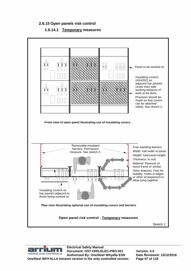
Electrical Safety Manual
Document: OST-OHS-ELEC-PRO-001 Version: 4.0
Authorised By: OneSteel Whyalla ESN Date Reviewed: 13/12/2016 OneSteel WHYALLA Intranet version is the only controlled version Page 67 of 118
2.6.15 Open panels risk control
1.6.14.1 Temporary measures
Open panel risk control - Temporary measures
Removable insulated barriers. Permanent
measure. See sketch 2.
Sketch 1
Plan view illustrating optional use of insulating covers and barriers
Free standing barriers.
Width: half width of panel.
Height: total panel height.
Thickness: to suit.
Material: Plywood on wood frame or similar.
Other features: Feet for stability. Holes in edges or other arrangement to allow tying together.
Front view of open panel illustrating use of insulating covers
Insulating cover/s on live panel/s adjacent to those being worked on
Insulating cover/s (AS4202) on adjacent live panel/s closer than safe working distance of work to be done.
Provision should be made so that covers can be attached safely. See sketch 2.
Panel to be worked on

Electrical Safety Manual
Document: OST-OHS-ELEC-PRO-001 Version: 4.0
Authorised By: OneSteel Whyalla ESN Date Reviewed: 13/12/2016 OneSteel WHYALLA Intranet version is the only controlled version Page 68 of 118
1.6.14.2 Permanent measures
Insulating mat AS2978 Class A on floors or use personal insulating mat.
Sketch 1: Provide means at the top of each panel, eg holes or insulated eyes, to enable safe fixing of insulating covers.
Insulate outgoing side of main switches
Cover unexpected live parts with insulating enclosures.
Front panel screening, eg insulated lattice roller shutter
NO GO areas indicated on floor.
Side panel barrier system, eg fixed insulated screens
Barrier systems. See plan view
Busbar droppers continuously insulated with ‗Wrap around‘ heat shrink tube or similar to control risk of electric shock while accessing rear of panel.
Removable insulated barriers, with Danger sign, to prevent casual access to rear of panel so that barrier must be deliberately removed to gain access, eg insulated chain. Non-Electrical worker not permitted behind panel without suitable training and Electrical Supervisors authority.
Removable insulated barrier with Danger sign. See Plan view.
Mesh cage around open resistors and similar to control risk of inadvertently touching live conductors.
Sketch 2
Open Panel risk control: Permanent measures
DANGER
AUTHORISED ENTRY ONLY
or

Electrical Safety Manual
Document: OST-OHS-ELEC-PRO-001 Version: 4.0
Authorised By: OneSteel Whyalla ESN Date Reviewed: 13/12/2016 OneSteel WHYALLA Intranet version is the only controlled version Page 69 of 118
2.7 ELECTRICAL TESTING
2.7.1 Electrical Testing, General
Any activity near live conductors has potential hazards of electrical shock or injury from arc blast or arc flash.
Electrical testing (refer definition) on LV and above is electrical work. Implement the testing and fault finding JSEA for low risk testing and fault finding. For testing or fault finding that is not low risk conduct a risk assessment, prepare a SSOW and have a Safety Observer present. Mandatory testing applies for some equipment, in particular:
In service testing of portable electrical equipment.
Regular testing of fixed, e.g. emergency equipment.
CoC / CCEW for all new installations and circuit / equipment changes.
2.7.2 Electrical Testing Safety
High transient voltages may be present during testing and could cause injury from high-energy arc faults if the test instrument does not have sufficient transient over voltage protection.
To ensure safety when testing it shall always be done with suitable test equipment. Testing for isolation shall follow the „Test before You Touch‟ procedure and shall test for the presence of both system and induced voltage. Safety when undertaking electrical testing is important and must never be compromised, regardless of production / time pressures.
Testing and fault finding guidelines on a CIRCUIT
The acronym CIRCUIT is a useful guideline for testing and faultfinding.

Electrical Safety Manual
Document: OST-OHS-ELEC-PRO-001 Version: 4.0
Authorised By: OneSteel Whyalla ESN Date Reviewed: 13/12/2016 OneSteel WHYALLA Intranet version is the only controlled version Page 70 of 118
SUMMARY of „CIRCUIT‟ GUIDELINE FOR TESTING and FAULT FINDING
Competent to do the job?
Adequately trained and experienced on equipment? If not seek assistance.
Identified all the hazards?
Complete the Electrical SSOW or PTRA and determine if the task is low risk or not. Take appropriate actions described in the SSOW in either case.
e.g. live equipment, production/time pressures, hazard register, cramped, hot or damp conditions, stored energy, multiple feeds, test equipment correct, moving machines.
Reduced the risk?
Eliminate hazards if possible or minimise with insulated barriers or screens etc or use personal protective equipment if necessary.
Checked your test equipment?
Ensure test equipment is appropriate; ensure test equipment is operational before use.
Understand the circuit and process?
Talk to operator or others familiar with operation, how should equipment operate? Fault continuous or intermittent? Sequence of events? Hardware or software changes? Operate equipment & observe. Look manuals/ drawings. Safety interlocks.
Investigated and repaired?
Appropriate tests at completion, e.g. earth continuity, insulation test, transposition of active/neutral, polarity etc. No unauthorised changes made? Returned to service in original state or documentation if modifications made.
Test your test equipment again!
Ensure the test equipment is operational on completion of the job.

Electrical Safety Manual
Document: OST-OHS-ELEC-PRO-001 Version: 4.0
Authorised By: OneSteel Whyalla ESN Date Reviewed: 13/12/2016 OneSteel WHYALLA Intranet version is the only controlled version Page 71 of 118
2.7.3 Test Meters
All test equipment, except test lamps or other special exempted equipment, shall have been type tested to comply with IEC1010.
Steady state 600 volt or higher; and
Transient over voltage protection Category IV as a minimum
Warning: Some digital meters may not indicate that a dangerous voltage exists when they automatically switch to a default range (true RMS meters are preferred), or when battery voltage is low (do not continue testing). Test equipment shall be calibrated for indication accuracy according to Australian Standards and State Regulations. The Plant Electrical Supervisor is responsible for calibration and shall hold records for at least 2 years. Application of Test Meter Categories
Test Lamps Test lamps are useful in testing for the presence of inducted voltage. Other test equipment Contact type test screwdriver with neon indictor: These are not permitted on OneSteel sites. Proximity type ‗volt stick‘: May be used as an aid to testing but not regarded as a definitive test for the presence or absence of voltage. High voltage test equipment: Refer to High Voltage Manual
O
F
F
V Cat IV Cat III Cat II Cat I
Single phase appliances
Electronics Main supply and outdoor conductors
Overvoltage protection Category for electrical test equipment to standard IEC1010 caters for protection from steady state and transient voltages and high-energy arc faults It covers up to 3-phase distribution and relates to the location in the electrical distribution system and caters for the energy available as well as the voltage.
Three and single phase distribution
Electrical Safety Manual
Document: OST-OHS-ELEC-PRO-001 Version: 4.0
Authorised By: OneSteel Whyalla ESN Date Reviewed: 13/12/2016 OneSteel WHYALLA Intranet version is the only controlled version Page 72 of 118
2.7.4 Modification and Process Change Control
Modification and process change can cause unforseen / hazardous situations in other parts of the plant. Modifying safety interlocks, e.g. bridging, introduces the risk of injury from inadvertent movement of machinery or release of energy.
Equipment shall not be modified or process changed without permission of the plant owner and considering the effect on other equipment and plant, taking into consideration the Management of Change (Modification Control) Code of Practice. If safety interlocks and similar are defeated or modified to allow testing of equipment or short term operation the procedure involves:
Risk assessment done and written testing and / or operating procedures prepared for approval by the plant owner; and
Follow-up action promptly implemented to return the interlocks to a safe condition.
2.7.5 In Service Testing of Portable Electrical Equipment
A high proportion of electrical fatalities are related to the use of portable electrical equipment.
All electrical equipment as defined in AS3760 and welding machines in AS1674.2, on OneSteel plant, shall be tested, inspected and tagged in accordance with State Regulations. A visual inspection shall still be routinely done before use to ensure it has not suffered obvious damage since the last test. Equipment, which has not been tested, inspected and appropriately tagged, shall be removed from service and a warning tag attached and shall not be connected to a OneSteel socket outlet until inspected, tested and tagged.
Inspecting/testing shall be done at the events specified, i.e.:
Prior to introduction into service;
After repair, before return to service; and
Hired equipment: at regular intervals specified or before each hire.
Movable/stationary equipment: when installed and after relocation.

Electrical Safety Manual
Document: OST-OHS-ELEC-PRO-001 Version: 4.0
Authorised By: OneSteel Whyalla ESN Date Reviewed: 13/12/2016 OneSteel WHYALLA Intranet version is the only controlled version Page 73 of 118
Contractors, manufacturer‘s representatives, equipment suppliers and others demonstrating products or making presentations shall ensure that all of their, and other employees, equipment brought onto OneSteel property is tested / inspected and tagged in accordance with the State Regulations.
2.7.6 Mandatory regular testing of fixed equipment
Some fixed equipment requires regular testing to ensure its reliability.
Safety equipment such as emergency stops and controls.
Other fixed equipment where required.

Electrical Safety Manual
Document: OST-OHS-ELEC-PRO-001 Version: 4.0
Authorised By: OneSteel Whyalla ESN Date Reviewed: 13/12/2016 OneSteel WHYALLA Intranet version is the only controlled version Page 74 of 118
2.8 EARTHING, POWER AND LIGHTING
2.8.1 Earthing Equipment Before Electrical Work
Some work on electrical equipment has a high risk potential if an electric shock occurs e.g. a High Voltage shock, working in environments that can increase secondary risk of injury or a fatality, e.g. falling from elevated equipment following a non-fatal electric shock.
After isolation and proving dead, the normally live conductor of the following equipment shall be earthed & bridged out across phases as an additional safety measure before work is done on them:
High Voltage equipment as specified in HV Manual
The supply cables for low voltage collector rails and any other elevated electrical equipment specified.
Earthing other electrical equipment before doing maintenance on it is recommended where possible and shall be covered in the ATW documentation.
2.8.2 Primary Protection from an Earth Fault
Protection from an electric shock, which results from an earth fault on electrical equipment relies in most cases entirely on the integrity and effectiveness of the connection to the electrical earth system.
All electrical installation and maintenance work shall strictly comply with the earthing requirements of the relevant Australian Standards, particularly AS3000 and with business unit‘s Electrical Installation Manual. The installer is responsible for Earthing measurements / tests. Recorded results are part of the notification of ‗Certificate of Compliance‘ and shall also be given to area Electrical Maintenance Supervisor or the plant manager if no electrical supervision available. It is vital that the primary earth protection is maintained and that any additional protection system is regarded as a supplement only.
2.8.3 Supplementary Protection from an Earth Fault by RCD (Residual Current Device)
Supplementary protection from electrical shock is provided by earth leakage detection and rapid isolation of power so the leakage through the body will be limited to non-fatal shock. RCD‟s mandatory
Electrical Safety Manual
Document: OST-OHS-ELEC-PRO-001 Version: 4.0
Authorised By: OneSteel Whyalla ESN Date Reviewed: 13/12/2016 OneSteel WHYALLA Intranet version is the only controlled version Page 75 of 118
It is mandatory that RCD‘s are provided in the power supply to all low voltage portable and movable electrical equipment supplied through a socket outlet, including portable generator outlets. All fixed 240V single and 415V 3 phase socket outlets on OneSteel sites shall have fixed RCD protection complying with business unit Electrical Installation Manual. The outlets shall be identified as being RCD protected with the wording ‖RCD PROTECTED‖*. (*Whyalla requirement) It is not necessary to use a portable RCD with a circuit, which has fixed RCD protection. An outlet without RCD identification shall not be used. Exemption from RCD protection will only be considered where circumstances prevent the use of an RCD. There are usually preferred alternatives such as hard wiring. Exemptions request should be sent to the business unit‘s Lead Electrical Engineer who will undertake a risk assessment.
The following information on RCD‟s should be understood:
1. Supplementary protection only. Primary earth protection must be strictly maintained.
2. Equipment with fixed wiring, apart from socket outlets, is not usually protected by an RCD.
3. RCD‘s must be regularly tested during service.
4. An RCD does not protect against:
✖ Electric shock but rapidly disconnects the supply to prevent death.
✖ Where no leakage to earth, e.g. simultaneous contact with active and neutral;
✖ Contact with another power supply such as when drilling into a live embedded cable in a wall, floor or ceiling;
✖ Electric shock from welding circuits.
5. May not protect when using appliances with inbuilt semiconductors e.g.
speed controlled drills, hair dryers. DC component of wave partially saturates RCD current transformer.

Electrical Safety Manual
Document: OST-OHS-ELEC-PRO-001 Version: 4.0
Authorised By: OneSteel Whyalla ESN Date Reviewed: 13/12/2016 OneSteel WHYALLA Intranet version is the only controlled version Page 76 of 118
2.8.4 Power Distribution
Power distribution by socket outlet shall be protected by a 30ma RCD.
2.8.5 Lighting
All new lighting installations shall be protected by a 30ma RCD. Light Fitting, Emergency Lamps and battery systems shall be regularly maintained and tested as specified in the standards and regulations. Recommended that emergency light fittings with internal rechargeable batteries be used rather that separate emergency supplies.
Lighting for rotating machinery
Discharge lamps have a 50 Hertz flicker, which can make rotating objects appear stationary or slow moving (stroboscopic effect).
How an RCD operates Supplementary protection from an earth fault is provided by an RCD. It monitors current flow to and from an electrical load and switches off if there is an imbalance greater than its rated tripping current.
Active
Neutral
Earth
Ia
In
If Fault current
Trip Coil Core balance Transformer
RCD
Ma
Mn
Fault Condition
A residual fault current flows, there is an out of balance field generated in the core balance t/f and the trip coil is energised
Residual fault current (If) through persons body
Current Ia > In
Magnetic field Ma > Mn
Output energises trip coil
10 mA or 30 mA RCD? Both 10mA (type I) and 30mA (type II) protect against harmful electric shock in domestic and industrial. 10mA units may be more prone to nuisance tripping. For ‗typical‘ electric shocks, protection given by 30mA RCD is identical to 10mA. Instantaneous current flow (typically 200mA for 240 volt) is determined by voltage & body resistance. RCD does not limit current but only acts to switch off rapidly. For „typical‟ 200mA fault both 10 & 30mA RCD‟s are required by AS3190 to switch off within 40ms and in practice switch at less than 20ms. Only for prolonged low current 10-30mA for several seconds that 10mA unit is needed. Typically medical/ dental treatment with very low resistance body paths.

Electrical Safety Manual
Document: OST-OHS-ELEC-PRO-001 Version: 4.0
Authorised By: OneSteel Whyalla ESN Date Reviewed: 13/12/2016 OneSteel WHYALLA Intranet version is the only controlled version Page 77 of 118
Where there is rotating / moving machinery the type and connection of artificial lighting shall ensure that the stroboscopic effect of discharge lighting does not create a hazardous situation. Light Fitting Maintenance
Maintenance of light fittings can cause electric shock form exposed conductors, broken fluorescent end holders or starters due to deterioration of the case from UV. Emergency lighting circuits could be supplied from a separate supply and are usually activated when the main circuit is isolated.
General maintenance of lighting fittings shall be as follows:
Use a non-conductive ladder.
Only replace lamps / tubes / starters without isolating circuit if:
Light switch is first switched off; and
Lamp / tube / starter case are first checked for damage.
If accessing interior of the light fitting, isolate / lockout and be aware of possible separate emergency lighting supply.
When maintaining light fittings on towers and high structures the hazard assessment shall consider at least the following:
Climbing restrictions for stairways and ladders to comply with AS1657.
Working at Heights requirements.
Other activities, e.g. traffic or material handling near the structures. Lamp Disposal
Injury from flying glass or adverse effects from mercury or sodium may result if lamps are broken before disposal.
There is a risk of fire when a low-pressure sodium lamp is broken.
Used lamps, except Low Pressure Sodium, should not be broken but handled with care using gloves, put in the protective jacket that comes with the replacement lamp and placed in the normal waste disposal bins, Before disposal the free sodium in the arc tube of low-pressure sodium lamps shall be de-activated. The safe method should be used such as follows:
Place in a dry metal container and break both the outer glass and inner arc tube. Wear gloves and eye protection to guard against glass fragments.
Allow several hours for the sodium in the arc tube to safety react with moisture in the air and then cover with water so that sodium is dissipated without causing a fire risk.

Electrical Safety Manual
Document: OST-OHS-ELEC-PRO-001 Version: 4.0
Authorised By: OneSteel Whyalla ESN Date Reviewed: 13/12/2016 OneSteel WHYALLA Intranet version is the only controlled version Page 78 of 118
Dispose of the remains in a safe manner in the normal waste disposal bin. Lighting, Portable Portable lighting policies apply as follows:
Tungsten Halogen floodlights should be designed for portable use, robust construction with toughened safety glass and have a substantial wire guard.
Only use Tungsten Halogen floodlights fitted with a wire guard. Tungsten Halogen floodlights must be used horizontal and the fitting
aimed 45 degrees or above, not straight down (to prevent heat build up).

Electrical Safety Manual
Document: OST-OHS-ELEC-PRO-001 Version: 4.0
Authorised By: OneSteel Whyalla ESN Date Reviewed: 13/12/2016 OneSteel WHYALLA Intranet version is the only controlled version Page 79 of 118
2.9 HIGH VOLTAGE SAFETY
2.9.1 High Voltage Safety, General
Uncontrolled access to HV equipment poses significant risks of death or severe injury. Electric shock from High Voltage, even if non-fatal, is usually more severe than a shock from Low Voltage in terms of injury and recovery time.
Only authorised persons shall have access to High Voltage equipment areas or work on High Voltage systems as specified in– High Voltage Manual. Single line diagram(s) showing all aspects of the High Voltage system shall be provided in a suitable display enclosure adjacent to the control and isolating switches in each High Voltage switchroom.
2.9.2 High Voltage Maintenance
Operating / maintaining HV switchgear requires training, experience and knowledge of HV principles and of the function of circuit breakers and circuit earthing devices. Equipment with high-energy spring charged mechanisms can cause severe injury.
Access to High Voltage equipment shall comply with High Voltage Manual. Maintenance of HV equipment will be by those authorised by OneSteel to undertake such work.
General safety guidelines for maintenance of HV equipment:
Live line test devices require verification of insulation and/or calibration of indication accuracy in accord with Aust Standards and State Regulations. Only personnel trained and authorised in their use shall test a HV conductor live/dead.
Application of HV circuit earthing shall be authorised by the relevant plant Switching Officer.
Application of an earth direct to circuit busbars is not permitted except when a Safe Work Procedure is Authorised by the business unit Lead Electrical Engineer or nominee.
Do not adjust circuit breaker mechanism without authorisation or direct supervision by OneSteel authorised HV personnel.
Do not leave the spring charge mechanism charged when maintaining the mechanism.
Do not modify protection device settings without reference to business unit HV Engineer. Any adjustment usually has an impact on overall plant protection.

Electrical Safety Manual
Document: OST-OHS-ELEC-PRO-001 Version: 4.0
Authorised By: OneSteel Whyalla ESN Date Reviewed: 13/12/2016 OneSteel WHYALLA Intranet version is the only controlled version Page 80 of 118
2.9.3 High Voltage Hazards
1. DANGER of NEAR APPROACH.
Maintain safe approach and work clearances.
Always test and earth before touching HV conductors.
2. STORED CHARGE/ RECHARGE if not earthed
Attach working earths or discharge conductors immediately before touching.
Capacitor equivalent Cable
Conductor
Insulation
Conductor
Armour
Sheath Memory
V
0
Recharge if not earthed
3. OPEN CIRCUIT CURRENT TRANSFOMERS
Turn main circuit OFF or short circuit connections before opening CT link or
CT secondary circuit wiring
V
0
Very high voltages are generated in the secondary winding of a loaded current transformer when it is open circuited by loose or open links and secondary circuit connections.
Main circuit i
4. FEEDBACK THROUGH REMOTE VOLTAGE TRANSORMERS Safe access generally requires both local and remote voltage t/fs to be isolated.
Kilometres
Remote LV source
Local LV source
Both power and voltage transformers are a possible
source of dangerous feedback through their low
voltage windings.

Electrical Safety Manual
Document: OST-OHS-ELEC-PRO-001 Version: 4.0
Authorised By: OneSteel Whyalla ESN Date Reviewed: 13/12/2016 OneSteel WHYALLA Intranet version is the only controlled version Page 81 of 118
2.9.4 Step and Touch Potential
Recommended emergency procedures
Stop and carefully examine surroundings. Look for point of electrical contact, fallen cables etc.
Do not touch cables or metal objects which may be live.
Do not walk around or attempt to rescue victims.
If in machine stay there. Break the contact from live cable or conductors and drive machine well clear (around 10 metres). If unable to move machine stay in it and wait.
If necessary to leave machine, eg fire, jump clear landing with feet together without touching vehicle.
To leave hazardous site jump with feet together or take short ‗shuffle‘ steps until 10 metres clear.
Wait until power is isolated before rescuing victims.
Examples of Hazardous „voltage gradient‟ situations:
Underground cable cut during excavation. Excavator becomes live.
Crane boom contacts live aerial conductor. Crane becomes live
Aerial power line contacts pole or falls to ground. Pole and ground at foot of pole become live.
Point of maximum potential Example 3,000 volts
Example of approximate ‗step‘ and ‗touch‘ potential from surface voltage ‗gradient‘ Note: Actual step and touch voltages vary widely but can easily reach lethal levels
2,500
2,000
1,500
1,000
500
0
Step 0 volt
Touch 500 volt
Step 250 volt Step 750 volt

Electrical Safety Manual
Document: OST-OHS-ELEC-PRO-001 Version: 4.0
Authorised By: OneSteel Whyalla ESN Date Reviewed: 13/12/2016 OneSteel WHYALLA Intranet version is the only controlled version Page 82 of 118
2.10 SPECIAL SITUATIONS
2.10.1 Construction Sites
Electrical equipment used for work on Construction site is subject to severe hazards.
Electrical installations, equipment and its use on Construction sites shall comply with AS3000 and AS3760.
2.10.2 Adverse Environments
All electrical equipment shall be FIT FOR PURPOSE and designed and installed to suit the environment it will be subject to or used only in the environment it is suitable for. Water and Electrical Equipment
Where water (dampness / steam / high humidity) is associated with use of electrical equipment the potential for a severe or fatal electric shock is significantly increased.
Only suitably constructed and installed electrical equipment may be used in damp or wet situations. Fixed electrical equipment shall be supplied and installed with an IP rating at least complying with business unit Electrical Installation Manual and AS3000 zones for damp situations. Design and location shall take into account the nature of the area, particularly for abnormal environment areas. Indiscriminate spraying / hosing of water around or on to electrical equipment is hazardous and is not permitted. Where water is unavoidably associated with the use of portable electrical equipment a risk assessment of potential hazards shall be done and safe work practices introduced.
Any special equipment, e.g. water cooled electric drills, shall first be inspected and approved by Electrical Inspection Officer and a safe procedure adopted. This may include at least:
Use seals to contain the water for water cooled tools;
Fit good quality water connections which will not part during use and are located away from electrical equipment in case of failure;
Keep electrical connections clear of water;
Use IP56 minimum rated electrical equipment including all plug & socket connections in areas where splashing or spraying cannot be eliminated.
Electrical Safety Manual
Document: OST-OHS-ELEC-PRO-001 Version: 4.0
Authorised By: OneSteel Whyalla ESN Date Reviewed: 13/12/2016 OneSteel WHYALLA Intranet version is the only controlled version Page 83 of 118
2.10.3 Confined Space
No work shall be done in a ‗Confined Space‘, without induction, a permit for the hazards present and the plant owner‘s authorisation.
2.10.4 Hazard Zones (harmful gas atmosphere)*
No work shall be done in a ‗Hazard Zone‘, (harmful atmosphere) without induction, a permit for the hazards present and the plant owner‘s authorisation. ‗Hazard Zones‘ (harmful atmosphere) are those where gases or vapours are or may be present in harmful quantities and are identified by different coloured areas as specified in the General Safety Handbook. * Whyalla specific
2.10.5 Hazard Areas
Working in a “Hazardous Area” with unsuitable tools, personal effects or clothing could cause injury or death through ignition of flammable gas or dust.
A dangerous situation may result if a “Hazardous Area” has unsuitable equipment or incorrect maintenance, which could create an ignition source.
‗Hazardous Areas‘ as defined in AS61241, are those areas where explosive atmospheres are or may be present and suitable electrical equipment is either ‗intrinsically safe‘ or ‗explosion protected‘ types Plant Owners shall be aware of AS61241 defined ‗Hazardous Areas‘ within their plant and enforce policies for their safe management so that ignition sources are eliminated. Ignition sources include incorrect or poorly maintained electrical equipment, tools and personal effects including some clothing.
Policies for safe maintenance of „Hazardous Areas‟
Equipment shall comply with the standards for the areas classification as specified in AS61241 and other relevant Australian Standards;
Maintenance procedures and records, including the statutory scheduled inspections, shall be documented and held by the plant owner as specified in the Australian Standards; and
No maintenance shall be done without induction, a permit for the hazards present and the plant owner‟s authorisation.

Electrical Safety Manual
Document: OST-OHS-ELEC-PRO-001 Version: 4.0
Authorised By: OneSteel Whyalla ESN Date Reviewed: 13/12/2016 OneSteel WHYALLA Intranet version is the only controlled version Page 84 of 118
1.10.5.1 Definitions:
In AS/NZS 60079.10 it is defined as an area in which ―an explosive gas atmosphere is present, or may be expected to be present, in quantities such as to require special precautions for the construction, installation and apparatus‖. Class 1 Gases.
Zone 0 – a place in which an explosive atmosphere consisting of a mixture with air of flammable substances in the form of a gas, vapour or mist is present continuously or for long periods or frequency. Zone 1 – a place in which an explosive atmosphere consisting of a mixture with air of flammable substances in the form of a gas, vapour or mist is present likely to occur in normal operations occasionally. Zone 2 – a place in which an explosive atmosphere consisting of a mixture with air of flammable substances in the form of a gas, vapour or mist is not likely to occur in normal operation, but if it does occur, will persist for a short period only. In AS/NZS 61241.10 it is defined as ―an area in which combustible dust in a cloud form is or can be expected to be present in quantities such as to require special precautions for the construction and use of equipment in order to prevent ignition of an explosive dust / air mixture.‖
Class 2 Dust
Zone 20 – a place in which an explosive atmosphere, in the form of a cloud of combustible dust in air, is present continuously, or for long periods or frequently. Zone 21 – a place in which an explosive atmosphere, in the form of a cloud of combustible dust in air, is likely to occur occasionally in normal operation. Zone 22 – a place in which an explosive atmosphere, in the form of a cloud of combustible dust in air, is not likely to occur in normal operation but, if it does, will persist for a short period only.
1.10.5.2 Safety Principles:
Installations in which flammable materials are handled or stored should be designed, operated and maintained so that any release of flammable materials, and consequently the extent of hazardous area‘s, kept to a minimum, whether in normal operation or otherwise, with the regard to frequency, duration or quantity. In a situation in which there may be an explosive atmosphere, the following steps should be taken:
Electrical Safety Manual
Document: OST-OHS-ELEC-PRO-001 Version: 4.0
Authorised By: OneSteel Whyalla ESN Date Reviewed: 13/12/2016 OneSteel WHYALLA Intranet version is the only controlled version Page 85 of 118
a) Eliminate the likelihood of an explosive atmosphere occurring around the source of the ignition, or
b) Eliminate the source of ignition. Where this is not possible, protective measures, process equipment, systems and procedures should be selected and prepared so the likelihood of the coincidence of a) and b) is so small as to be acceptable. Such measures may be used singly, if they are recognised as being highly reliable, or in combination to achieve an equivalent level of safety.
1.10.5.3 Areas Classification:
Area classifications is a method of analysing and classifying the environment where explosive atmospheres may occur so as to facilitate the proper selection and installation of apparatus to be used safely in that environment, taking into account other information (i.e. gas groups, temperature classes etc) It is rarely possible by a simple examination of a plant or plant design to decide which parts of the plant can be equated to the three zone definitions. A more detailed approach is therefore necessary and this involves analysis of the basic possibility of an explosive atmosphere. Those who have knowledge of the properties of flammable materials, the process and the equipment, in consultation, as appropriate, with safety, electrical, mechanical and other engineering personnel, should carry out the area classification. The area classification should be carried out when the initial process and instrumentation line diagrams and initial layout plans are available and confirmed before plant start-up. Reviews should be carried out during the life of the plant. Once a plant has been classified and all necessary records made, it is important that no modification to equipment or operating procedures is made without discussion with those responsible for the area classification. Unauthorised actions may invalidate the area classification. It is necessary to ensure that all equipment affecting the area classification, which has been subjected to maintenance is carefully checked during and after re-assembly to ensure that the integrity of the original design, as it effects safety, has been maintained before it is returned to service.
1.10.5.4 Documentation
It is recommended that the area classification is undertaken in such a way that the various steps, which lead to the final area classification, are properly documented. All relevant information used shall be referred to examples of such information, or a method used include:
Recommendations from relevant codes and standards.
Gas and Vapour dispersion characteristics and calculations.

Electrical Safety Manual
Document: OST-OHS-ELEC-PRO-001 Version: 4.0
Authorised By: OneSteel Whyalla ESN Date Reviewed: 13/12/2016 OneSteel WHYALLA Intranet version is the only controlled version Page 86 of 118
A study of ventilation characteristics in relation to flammable material release parameters so that the effectiveness of the ventilation can be evaluated.
Assessment of dust dispersion from sources of release.
Process parameters, which influence the formation of dust / air mixtures and dust layers.
All documentation in relation to the Hazardous Area is to be kept in a Dossier by the relevant plant. The Dossier should include the following:
Area Classification Report.
Outline of method used to classify the area.
Diagrams which show: Zone(s), apparatus groups, temperature classification, special conditions.
Compliance Certificate for equipment to be used in area.
Maintenance Records (Commissioning and on going.)
2.10.6 Energy Radiating Devices
Ionizing Radiation (radio-active devices)
Only authorised people are to work on radiation emitting devices.
Do not enter area with radiation warning signs.
If a radioactive device is damaged, clear and flag off the area for a minimum of 5 metres and notify the plant supervisor or Environment Department promptly.
Laser including Optical Fibre Cables
Only authorised people are to work on laser devices.
Do not enter area with laser warning signs.
Do not look directly into a laser beam or move into its path.
Optical fibre cables use invisible laser beams, which can damage the back of the eye. Do not look into to check if operating. Glass core fragments can also cause damage if they penetrate skin. Clean up the site. Laser Pointing Pens are not considered dangerous to eyesight due to blink reflex, but do not stare into a beam. Use with care as even brief exposure may cause distraction and temporary loss of vision. Microwaves Microwave ovens should be inspected regularly, used in accord with manufacturers instructions and repaired before use if damaged or distorted.

Electrical Safety Manual
Document: OST-OHS-ELEC-PRO-001 Version: 4.0
Authorised By: OneSteel Whyalla ESN Date Reviewed: 13/12/2016 OneSteel WHYALLA Intranet version is the only controlled version Page 87 of 118
2.10.7 Communication devices, Mobile Telephones, etc
Communication devices such as mobile telephones or hand held radios shall not be used in close proximity to electrical or electronic equipment, which may be affected or near flammable sources such as petrol bowsers and hazardous areas. Recommended closest distance is 3 metres. Electromagnetic fields affecting Pacemakers and body implant/s People with Pacemakers or metal plate implants should seek medical advice and consult their supervisor before working close to electrical equipment, which generates or uses high frequencies or strong magnetic fields.
2.10.8 Emergency Equipment
Equipment, which only operates during emergency, e.g. emergency stops, shall be rigorously maintained so that it will perform reliably when required. Some maintenance procedures are mandatory. Emergency stops and similar shall be maintained through routine testing. Emergency lighting – battery and lamp tests Battery back-up systems, single point and central, require tests and discharge cycles at prescribed intervals to maintain their health and test their capability. Emergency evacuation warning – maintenance and tests Where an Emergency (evacuation) Warning and Intercom system EWIS is installed in buildings, the maintenance and tests shall comply with AS4428.4.
2.10.9 Redundant Equipment Removal
Demolition of Electrical Equipment
All decommissioning, demolition and removal of electrical equipment and plant shall comply with business unit‘s relevant work instruction and this manual.
Electrical Safety Manual
Document: OST-OHS-ELEC-PRO-001 Version: 4.0
Authorised By: OneSteel Whyalla ESN Date Reviewed: 13/12/2016 OneSteel WHYALLA Intranet version is the only controlled version Page 88 of 118
Redundant Cables
Wherever possible, redundant electrical cables shall be completely removed as soon as they are no longer required.
Before removing cables, they shall be traced to their source of supply and isolated. If it is necessary to cut sections of the cable to remove it, keep sections short to avoid cutting the wrong cable. This work shall be done to comply with the requirements for decommissioning, demolition and removal of Electrical equipment.
Where it is impractical to immediately remove a redundant cable it shall be removed from its terminals and cut back to prevent re-termination. Both ends shall be capped with a suitable heat shrink fitting. Metallic tags shall be fitted to each end of the cable to identify it and the location of the other end. A documented plan to remove the cable shall be developed and a copy promptly forwarded to the business unit‟s Lead Electrical Engineer.
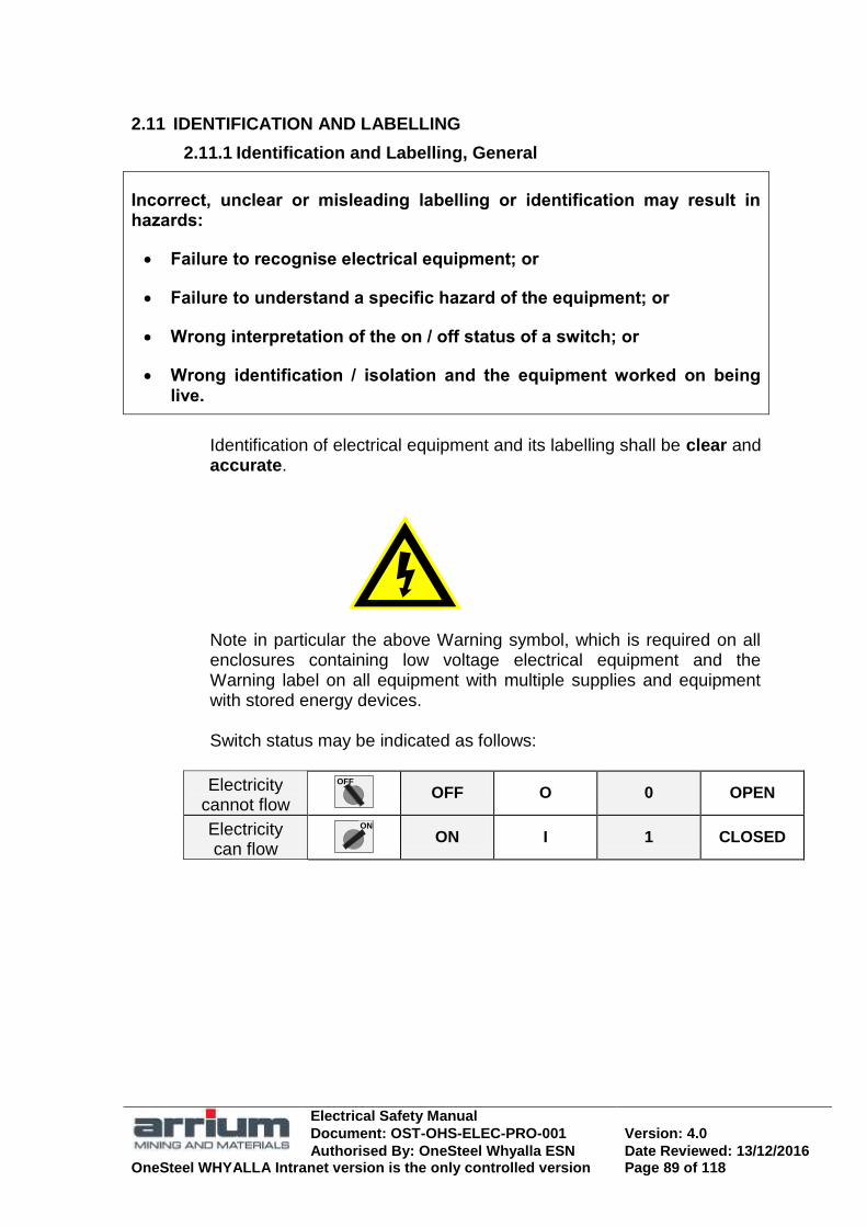
Electrical Safety Manual
Document: OST-OHS-ELEC-PRO-001 Version: 4.0
Authorised By: OneSteel Whyalla ESN Date Reviewed: 13/12/2016 OneSteel WHYALLA Intranet version is the only controlled version Page 89 of 118
2.11 IDENTIFICATION AND LABELLING
2.11.1 Identification and Labelling, General
Incorrect, unclear or misleading labelling or identification may result in hazards:
Failure to recognise electrical equipment; or
Failure to understand a specific hazard of the equipment; or
Wrong interpretation of the on / off status of a switch; or
Wrong identification / isolation and the equipment worked on being live.
Identification of electrical equipment and its labelling shall be clear and accurate.
Note in particular the above Warning symbol, which is required on all enclosures containing low voltage electrical equipment and the Warning label on all equipment with multiple supplies and equipment with stored energy devices. Switch status may be indicated as follows:
Electricity cannot flow
OFF
OFF O 0 OPEN
Electricity can flow
ON
ON I 1 CLOSED

Electrical Safety Manual
Document: OST-OHS-ELEC-PRO-001 Version: 4.0
Authorised By: OneSteel Whyalla ESN Date Reviewed: 13/12/2016 OneSteel WHYALLA Intranet version is the only controlled version Page 90 of 118
2.11.2 Identification of control and signal units
Standard colour for electrical equipment enclosures and for pipes and conduit which enclose cables is X15 orange..
This symbol on equipment or an enclosure indicates an electrical supply that is potentially hazardous.
Control buttons function and detail (based on AS60947.5.1)
Function Detail and Notes
Stop or
Red Plain or with symbol
Emergency Stop
Red
Large Red „Mushroom.
Intervention Yellow
To avoid unwanted change
Start
or
Green Plain or with symbol
Assigned meaning Blue
A function not covered by red, green or yellow
No specific meaning Black
Any function except „Stop‟ or „Off‟‟
Indicator lights function and detail (based on AS60947.5.1)
Function Detail and Notes (Flashing signal to draw attention)
Danger or alarm* Red
e.g. pressure outside safe limits, parts live
Warning or Caution Yellow
e.g. pressure not normal, action required
Safety* Green
e.g. cooling liquid OK, machine ready to start
Assigned meaning Blue
e.g. indication of remote control
No specific meaning White
When doubt about meaning of red, yellow or green, e.g. motor running
*Existing practice which conflicts with the above meanings, e.g. where red/green indicators are used for the closed/open position of circuit breakers, may continue where change could cause confusion or a hazardous situation. Refer AS60947.5.1.

Electrical Safety Manual
Document: OST-OHS-ELEC-PRO-001 Version: 4.0
Authorised By: OneSteel Whyalla ESN Date Reviewed: 13/12/2016 OneSteel WHYALLA Intranet version is the only controlled version Page 91 of 118
2.11.3 Safety signs for Hazard Identification
The supply and installation of common Safety signs for Hazard Identification is shown.
Sign function Symbolic Shape Examples
Prohibition
Red on White Black legend
Digging prohibited
No Fire, Flame or Smoking
CONTAINERS OVER 8.5 T
PROHIBITED
Mandatory
Blue White legend
Wear Full Face Mask
Eye protection
Hearing protection
Foot protection
Warning Hazard
Black on Yellow Black legend
Laser Beam
Explosion Risk
Ionizing Radiation
Electric Shock Risk
Danger Hazard likely to
be life threatening
DANGER
White Danger on Red/Black
Black legend
HIGH VOLTAGE AUTHORISED PERSONS
ONLY
DANGER
HV Switchrooms
Entrance
ELECTRICAL EQUIPMENT AUTHORISED PERSONS
ONLY
DANGER
Exposed live collector rails LV
Switchrooms Entrance
LIVE RAILS DANGER
Emergency Information
Location of emergency
facilities
Green White legend
EMERGENCY EYE WASH
First aid Emergency Eye Wash
EMERGENCY EXIT
Fire sign Location of fire
alarms or extinguishers
Red White legend
FIRE ALARM FIRE HOSE
FIRE
EXTINGUISHER
Fire Extinguisher location
Dangerous Goods Class
Labels
(AS1216)
White, Orange, Red, Green, Blue or Yellow
Black legend
3
FLAMMABLE
LIQUID
FLAMMABLE
SOLID
4
RADIOACTIVE
7
CORROSIVE
8
Background colours
White/Black Yellow/White Red/White Red

Electrical Safety Manual
Document: OST-OHS-ELEC-PRO-001 Version: 4.0
Authorised By: OneSteel Whyalla ESN Date Reviewed: 13/12/2016 OneSteel WHYALLA Intranet version is the only controlled version Page 92 of 118
2.11.4 Identification of live exposed conductors
Live collector rails and similar, which can be approached closer than the recommended clearances or within ‗arm reach‘ shall be identified with appropriate danger signs. Signals shall be positioned so they can be readily seen from all approach points and spaced no more than 15 metres apart.
Collector rails identified by Danger Signs
LIVE RAILS DANGER
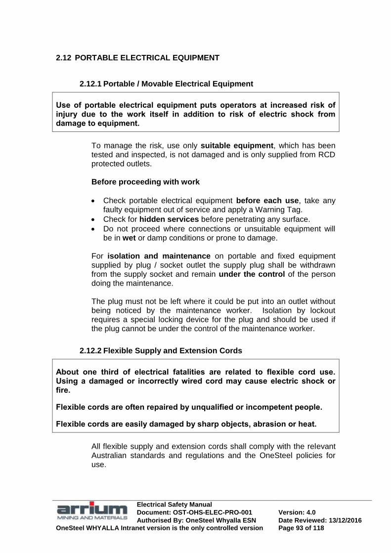
Electrical Safety Manual
Document: OST-OHS-ELEC-PRO-001 Version: 4.0
Authorised By: OneSteel Whyalla ESN Date Reviewed: 13/12/2016 OneSteel WHYALLA Intranet version is the only controlled version Page 93 of 118
2.12 PORTABLE ELECTRICAL EQUIPMENT
2.12.1 Portable / Movable Electrical Equipment
Use of portable electrical equipment puts operators at increased risk of injury due to the work itself in addition to risk of electric shock from damage to equipment.
To manage the risk, use only suitable equipment, which has been tested and inspected, is not damaged and is only supplied from RCD protected outlets. Before proceeding with work
Check portable electrical equipment before each use, take any faulty equipment out of service and apply a Warning Tag.
Check for hidden services before penetrating any surface.
Do not proceed where connections or unsuitable equipment will be in wet or damp conditions or prone to damage.
For isolation and maintenance on portable and fixed equipment supplied by plug / socket outlet the supply plug shall be withdrawn from the supply socket and remain under the control of the person doing the maintenance. The plug must not be left where it could be put into an outlet without being noticed by the maintenance worker. Isolation by lockout requires a special locking device for the plug and should be used if the plug cannot be under the control of the maintenance worker.
2.12.2 Flexible Supply and Extension Cords
About one third of electrical fatalities are related to flexible cord use. Using a damaged or incorrectly wired cord may cause electric shock or fire.
Flexible cords are often repaired by unqualified or incompetent people.
Flexible cords are easily damaged by sharp objects, abrasion or heat.
All flexible supply and extension cords shall comply with the relevant Australian standards and regulations and the OneSteel policies for use.

Electrical Safety Manual
Document: OST-OHS-ELEC-PRO-001 Version: 4.0
Authorised By: OneSteel Whyalla ESN Date Reviewed: 13/12/2016 OneSteel WHYALLA Intranet version is the only controlled version Page 94 of 118
2.12.3 Multi-outlet Devices (power boards / boxes)
Portable multi-outlet devices shall comply with AS3105 (Electrical Portable Outlet Devices) for office areas and AS61439.4(Portable Socket Outlet Assemblies) for workshops, outdoors and construction areas.
Common requirements for multi-outlet devices (power board/ box)
Current rating of any outlet not to be greater than that of supply plug or cord.
Robust construction
If three or more outlets, overload protection no greater than supply cord rating. Prevents connection of loads in excess of the rating, isolates faulty equipment and minimises damage and fire risk.
Specific requirements for Boards (EPOD AS3105)
Overload reset
Board
Be individually switched
If reeling or coiling arrangement for cord, must have over temperature protection.
Specific requirements for Boxes (Skt outlet ACS AS61439.4)
Overload and RCD
Box
IP rating appropriate for environment. Min IP43.
Supply cord heavy duty (1 or 3 ph), max length 1.8m.
Outlets protected by max 30mA RCD.
Double adaptors and ‗piggyback‘ plug adaptors are not permitted on OneSteel sites. Where there are multiple power boards in use at one location they should be replaced by additional permanent socket outlets.
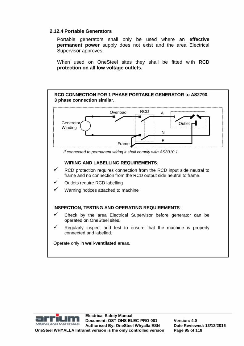
Electrical Safety Manual
Document: OST-OHS-ELEC-PRO-001 Version: 4.0
Authorised By: OneSteel Whyalla ESN Date Reviewed: 13/12/2016 OneSteel WHYALLA Intranet version is the only controlled version Page 95 of 118
2.12.4 Portable Generators
Portable generators shall only be used where an effective permanent power supply does not exist and the area Electrical Supervisor approves. When used on OneSteel sites they shall be fitted with RCD protection on all low voltage outlets.
Frame
Outlet
N
A
E
Overload RCD
If connected to permanent wiring it shall comply with AS3010.1.
GeneratorWinding
RCD CONNECTION FOR 1 PHASE PORTABLE GENERATOR to AS2790.
3 phase connection similar.
WIRING AND LABELLING REQUIREMENTS:
RCD protection requires connection from the RCD input side neutral to frame and no connection from the RCD output side neutral to frame.
Outlets require RCD labelling
Warning notices attached to machine
INSPECTION, TESTING AND OPERATING REQUIREMENTS:
Check by the area Electrical Supervisor before generator can be operated on OneSteel sites.
Regularly inspect and test to ensure that the machine is properly connected and labelled.
Operate only in well-ventilated areas.
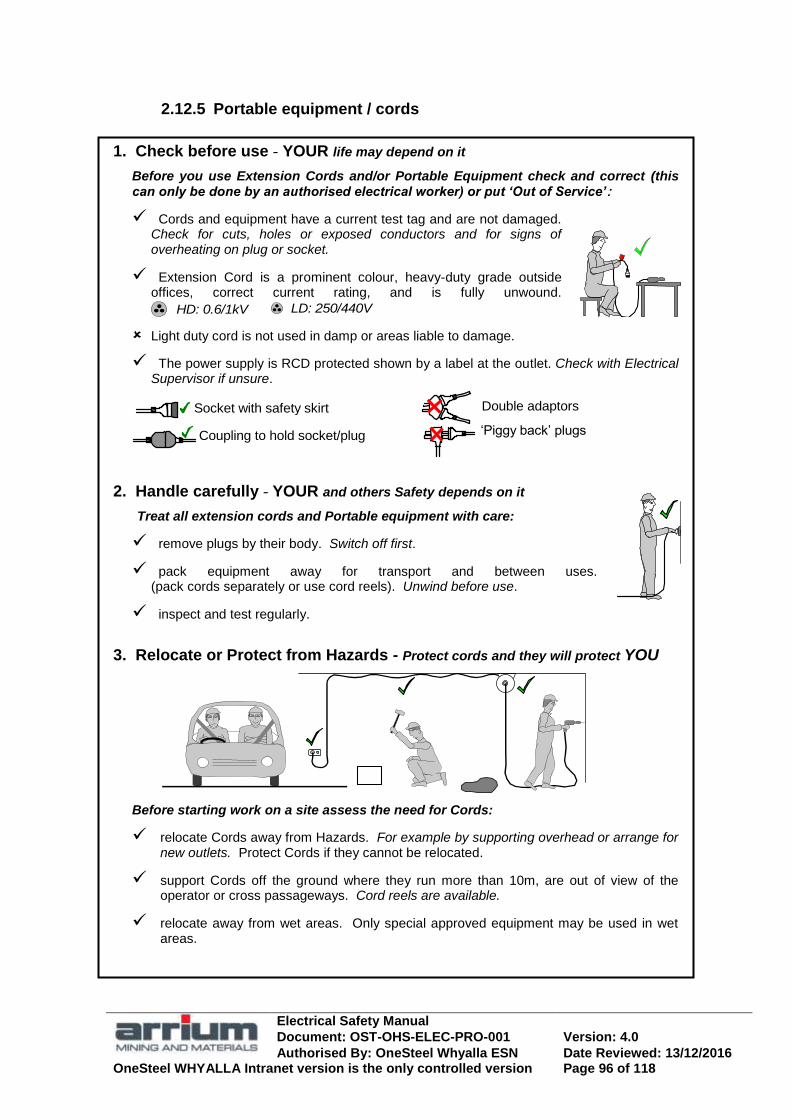
Electrical Safety Manual
Document: OST-OHS-ELEC-PRO-001 Version: 4.0
Authorised By: OneSteel Whyalla ESN Date Reviewed: 13/12/2016 OneSteel WHYALLA Intranet version is the only controlled version Page 96 of 118
2.12.5 Portable equipment / cords
1. Check before use - YOUR life may depend on it
Before you use Extension Cords and/or Portable Equipment check and correct (this can only be done by an authorised electrical worker) or put ‘Out of Service’:
Cords and equipment have a current test tag and are not damaged. Check for cuts, holes or exposed conductors and for signs of overheating on plug or socket.
Extension Cord is a prominent colour, heavy-duty grade outside offices, correct current rating, and is fully unwound.
HD: 0.6/1kV LD: 250/440V
Light duty cord is not used in damp or areas liable to damage.
The power supply is RCD protected shown by a label at the outlet. Check with Electrical Supervisor if unsure.
Coupling to hold socket/plug
Socket with safety skirt Double adaptors
‗Piggy back‘ plugs
2. Handle carefully - YOUR and others Safety depends on it Treat all extension cords and Portable equipment with care:
remove plugs by their body. Switch off first.
pack equipment away for transport and between uses. (pack cords separately or use cord reels). Unwind before use.
inspect and test regularly.
3. Relocate or Protect from Hazards - Protect cords and they will protect YOU
Before starting work on a site assess the need for Cords:
relocate Cords away from Hazards. For example by supporting overhead or arrange for new outlets. Protect Cords if they cannot be relocated.
support Cords off the ground where they run more than 10m, are out of view of the operator or cross passageways. Cord reels are available.
relocate away from wet areas. Only special approved equipment may be used in wet areas.

Electrical Safety Manual
Document: OST-OHS-ELEC-PRO-001 Version: 4.0
Authorised By: OneSteel Whyalla ESN Date Reviewed: 13/12/2016 OneSteel WHYALLA Intranet version is the only controlled version Page 97 of 118
2.12.6 Flexible extension cords
Characteristic Based on Standards & Regulations.
Sheath grade: Ordinary duty for use only in office areas. Heavy duty for other use. Identify grade by approx diameter of cord or voltage if stamped:
250/440V
OD 10amp 8mm 15amp 10mm
0.6/1kV
HD 10amp 10mm 15amp 12mm
(AS3000, AS3191, AS3199 “At least ordinary duty”. AS3012 “Heavy
duty in construction areas”).
Sheath colour: Prominent colour preferably orange. Not green.
(AS3012 “Shall not contain the colour green”.)
Core colours and connections:
Front of socket or rear of plug
Earth: Green/Yellow
Neutral: Light Blue (or Black) Active: Brown (or Red)
(AS3191, AS3199).
Conductor size: Not less than 1 mm
2 and up to 4
mm
2
(AS3000, AS3012, AS3191, AS3199).
Rating: 10, 15 or 20 amp. Plug & socket must be same rating.
(AS3199).
Extension Socket All new 10 amp sockets / plug tops from 2008 to have safety skirt and insulated pins.
Couplings are recommended for construction sites.
Adaptors: Double adaptors and ‗piggy back‘ plug adaptors are not permitted. (AS3012).
Rating amps
Cord area mm2
Max length m
10A/15A 20A 10A 15A 15A 10A
1.0 / 1.5 2.5 1.5 2.5 4.0 4.0
25m
30m
35m
40m
65m
100m
(AS3012:2003, “recommended that a single cord ext be used”)
Protection, support & running:
Locate where not subject to mechanical damage or from liquids or high temperature.
Support off floor or ground where:
In multilevel buildings shall be confined to the level of the switchboard they originate from except in stairwells, staging etc.
(AS3012).
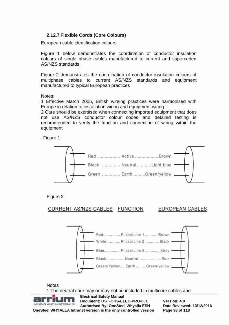
Electrical Safety Manual
Document: OST-OHS-ELEC-PRO-001 Version: 4.0
Authorised By: OneSteel Whyalla ESN Date Reviewed: 13/12/2016 OneSteel WHYALLA Intranet version is the only controlled version Page 98 of 118
2.12.7 Flexible Cords (Core Colours)
European cable identification colours Figure 1 below demonstrates the coordination of conductor insulation colours of single phase cables manufactured to current and superceded AS/NZS standards Figure 2 demonstrates the coordination of conductor insulation colours of multiphase cables to current AS/NZS standards and equipment manufactured to typical European practices Notes: 1 Effective March 2006, British wireing practices were harmonised with Europe in relation to installation wiring and equipment wiring 2 Care should be exersised when connecting imported equipment that does not use AS/NZS conductor colour codes and detailed testing is recommended to verify the function and connection of wiring within the equipment
. Figure 1
Figure 2
Notes 1 The neutral core may or may not be included in multicore cables and
Electrical Safety Manual
Document: OST-OHS-ELEC-PRO-001 Version: 4.0
Authorised By: OneSteel Whyalla ESN Date Reviewed: 13/12/2016 OneSteel WHYALLA Intranet version is the only controlled version Page 99 of 118
cords 2 The alternative European active colour for multiphase flexible cords and cables on all phases is brown
2.13 LIFTING AND HANDLING OF ELECTRICAL EQUIPMENT
2.13.1 Lifting and Handling of Electrical Equipment, general
When lifting electrical equipment, correct lifting procedures apply:
Lifting shall always be under the control and supervision of personnel with appropriate training;
Correct lifting equipment shall be used;
Correct built in lifting points utilised; and
Ensure all electrical cables have been disconnected and made safe.
Never lift a load until its weight is determined and the SWL / MRC of the lifting arrangement is calculated to be adequate.
Guidance on the safe use of eyebolts
Check the threads of eyebolts and tapped holes for any damage or mismatch before fitting;
Leave eyebolts in electrical equipment so that the thread does not fill and make it difficult to insert an eyebolt when needed.
Only use eyebolts, which display their safe load limit. May be SWL (Safe Working Load), WLL (Working Load Limit) or MRC (Maximum Rated Capacity).
Specifications for the safe use of eyebolts are as follows:
The surface, which the eyebolt collar contacts shall be smooth, flat and at right angles to the axis of the tapped hole.
Eyebolts shall be screwed in until the collar just contacts the surface of the object to be lifted. Avoid over tightening.
The body of the eye of the eyebolt shall be aligned within 5 degrees of position of the hook when lifting. If not insert flat shim.
Minimum thread engagement is that of a same diameter standard nut.

Electrical Safety Manual
Document: OST-OHS-ELEC-PRO-001 Version: 4.0
Authorised By: OneSteel Whyalla ESN Date Reviewed: 13/12/2016 OneSteel WHYALLA Intranet version is the only controlled version Page 100 of 118
2.14 WELDING ELECTRICAL SAFETY
2.14.1 Safe Electrical Supply and Welding Equipment
All M.M.A.W. (Manual Metal Arc Welding) power sources shall have a d.c. output and be fitted with an operating Voltage Reduction Device (VRD).
All welding and accessory equipment shall be maintained in a safe and sound condition and tested and inspected at intervals specified in the Australian Standards and Regulations.
Welding socket outlets to comply with this manual. When risk control measures require zero voltage between adjacent machine electrodes, they shall be tested / reconnected to suit.
Welding outlets / machines to be regularly tested during service.
Operator to make checks before plugging in welding machine. 240V Welder designed to be run off 15 amp sockets will only be plugged into 15 amp outlets.
2.14.2 Risk assessment of the welding environment
Welding voltages are relatively low but can cause death due to low resistance paths through the operator or others from damp, wet or hot conditions.
Additional risks can be caused by poor work and return path, higher than normal volts between adjacent machine electrodes and special HV arc initiation.
Before welding commences, the work area shall be assessed and the welding environment classified for risk of electric shock and electrocution and appropriate control measures taken.

Electrical Safety Manual
Document: OST-OHS-ELEC-PRO-001 Version: 4.0
Authorised By: OneSteel Whyalla ESN Date Reviewed: 13/12/2016 OneSteel WHYALLA Intranet version is the only controlled version Page 101 of 118
2.14.3 Classification of welding environment for risk of electric shock
Category, risk of electric shock Typical task
A: Low risk of welder becoming part of circuit. Normal work practice.
Bench-top welding/ small work piece, or large work-piece but welder prevented from contacting conductive parts.
B: Significant risk. In contact with conductive parts of work-piece.
Usually less than 32 C ambient.
General fabrication, large steel structures or restricted movement in tanks or confined space.
C: Greatly increased risk. Due to water, moisture or heat, particularly
for above 32 C ambient.
Coffer dams, trenches, in rain, fully or partly submerged and splash zones.
2.14.4 Safe welding work practices
Use risk control measures as in the table above and section 2.14.6.
Any electric shock received shall be treated as an emergency.
Operator to inspect welding accessories regularly. Replace faulty equipment. Insulation tape repair is not suitable.
Only all insulated type A electrode holders used for all welding.
Return clamp on job and as close as possible to point of welding.
Use safe procedures for special high voltage arc initiation equipment.
Never place G.T.A.W. (Gas Tungstan Arc Welding) torch close to your ear to check for gas flow.
Do not weld in area of explosive atmospheres.
Do not operate welding machine above the rated duty cycle.
2.14.5 Welding electrical safety
Welding socket outlets and welding equipment
The connection and polarisation of welding machines shall be such that polarity of output voltage is consistent, and adjacent machines will not present hazard of twice open circuit welding voltage between electrodes. This is based on AS1674.2.
The correct connection involves coordination of phase connections and polarity of machine windings.
Electrical Safety Manual
Document: OST-OHS-ELEC-PRO-001 Version: 4.0
Authorised By: OneSteel Whyalla ESN Date Reviewed: 13/12/2016 OneSteel WHYALLA Intranet version is the only controlled version Page 102 of 118
In service safety inspecting/ testing of electrical equipment
Each business unit ―In service safety inspecting/ testing of electrical equipment‖ work instruction shall includes inspecting/ testing of portable, fixed and engine driven welding machines. Test values are based on AS1674.2 and AS60974
AS1674.2 Welding, Electrical safety
AS1674.2 describes the practices and safeguards, which should be adopted by welders and the connections for AC and DC power sources. Classification of risk of electric shock and electrocution and control measures are given. It gives examples on how shocks can be received and the action to take in the event of electric shock.
AS60974.1 Electric arc welding power sources
AS60974.1specify design, performance and rating of various types of welding machines including maximum no-load output voltages.
AS60974.6 Approval and test specs for portable machines for elect arc welding
AS60974.6 outlines the safety matters and related conditions for single operator, portable welding machines operating from low voltage flexible cord and plug supply. It includes maximum no-load voltages and testing methods and safety requirements for hazard reducing devices including Voltage Reducing Device (VRD).
Voltage Reducing Device (VRD) safety requirements from AS60974.6
Reduces output voltage when output circuit resistance exceeds 200 ohms. Voltage should be less than 35Vd.c. Check compliance by connecting load resistor variable from 50 to 200 ohms while testing voltage.
Operates within 0.3 seconds after interruption of the output current.
Device, e.g. signal lamp, indicates satisfactory operation when voltage reduced.
Fails to a safe condition. HB94 Electrical safety in the workplace
Handbook HB94 covers general electrical safety in the workplace including welding safety. WTIA Tech Notes No.7 and 22 Health/ safety and electrical safety in welding.

Electrical Safety Manual
Document: OST-OHS-ELEC-PRO-001 Version: 4.0
Authorised By: OneSteel Whyalla ESN Date Reviewed: 13/12/2016 OneSteel WHYALLA Intranet version is the only controlled version Page 103 of 118
2.14.6 Welding, Electrical Risk Control Guide
Work connection
Insulated connectors
RCD protected outlet
15 amp for 240 volt
63 amp for 415 volt Check polarity.
Observer AS1674.2
Non flammable insulation
Wooden duckboard with dry insulating material. Drain excess water from area
Footwear with insulating soles or rubber boots
D.C. Supply with VRD
Adequate ventilation
All insulated electrode holder
See 2.14.7 for machine connections for adjacent welding.
Observer if required. AS 1674.2
Plant owner arranges regular in service electrical inspection of outlets, cords, welding machine and accessories.
Welder ensures own safety:
Check outlet, cords and plugs before plugging in a welding machine. See 2.12.5 „Portable equipment‟.
Keep leads, connections and accessories in good condition by inspecting before use and arranging any repairs.
Wear correct PPE including dry gloves and clothes.
Category A: Low risk general welding AS1674.2
Category B: Large workpiece/ Confined space
Work lead on the job. Stray current can cause an electric shock to others or damage equipment
Lighting from ELV or isolating T/F
AS1674.2
AS1674.2 Protective cover from falling water or rain
Welder wears dry clothing next to skin and protective outer clothing
Leads and accessories carefully checked for defects and supported above wet surfaces
DC supply with integral VRD (VRD may be external)
DC supply with integral VRD (VRD may be external)
Category C: Water, moisture, heat
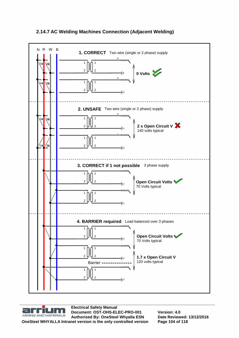
Electrical Safety Manual
Document: OST-OHS-ELEC-PRO-001 Version: 4.0
Authorised By: OneSteel Whyalla ESN Date Reviewed: 13/12/2016 OneSteel WHYALLA Intranet version is the only controlled version Page 104 of 118
2.14.7 AC Welding Machines Connection (Adjacent Welding)
Open Circuit Volts 70 Volts typical
Open Circuit Volts 70 Volts typical
0 Volts
1. CORRECT
Load balanced over 3 phases
3 phase supply
N
1.7 x Open Circuit V 120 volts typical Barrier
2
1
R B W
2
1
2
1
2
1
2
1
2
1
2
1
2
1
2
1
2
1
2
1
2
1
2
1
2
1
2 x Open Circuit V 140 volts typical
Two wire (single or 2 phase) supply
2
1
2
1
2
1
2
1
-
+
+
+
Two wire (single or 2 phase) supply
2. UNSAFE
3. CORRECT if 1 not possible
4. BARRIER required

Electrical Safety Manual
Document: OST-OHS-ELEC-PRO-001 Version: 4.0
Authorised By: OneSteel Whyalla ESN Date Reviewed: 13/12/2016 OneSteel WHYALLA Intranet version is the only controlled version Page 105 of 118
3 PART 2 SPECIFIC EQUIPMENT SAFETY
3.1 “A”
3.1.1 Alerts, Safety Briefs and Recalls
Safety Briefs are to be produced after all electrical Incidents and Accidents These are to be circulated plant wide in response to significant electrical incidents, safety topics or recall of equipment notices Safety incidents should also be communicated to the OneSteel Electrical Safety Network.
3.1.2 Alkaline battery
Batteries or alkaline cells (a battery being a collection of multiple cells) are a type of
disposable or rechargeable battery.
3.2 “B”
3.2.1 Batteries (storage), Work on or Near
Skin and eye damage can result from acid spills or splashes.
Flammable gases may be liberated from storage batteries.
When battery fluids are used to refill storage batteries appropriate PPE shall be worn and eye wash or shower facilities provided in close proximity. Prompt medial attention should be obtained. Aim of first aid is to dilute and eliminate the acid or alkali by flooding the eye or other affected parts immediately with water. Batteries shall be installed, maintained and replaced to AS2676 to ensure that Flammable gases released during charging and heavy discharge are adequately vented to atmosphere. Smoking and naked flame is prohibited. Flammable gases can be ignited by sparks while using metal objects such as spanners if the area ventilation is inadequate.
3.3 “C”
3.3.1 Cables a Conduits Penetrated by Screws
The penetrating power of TEK screws have caused electric shock, supply interruption and fire risk incidents.

Electrical Safety Manual
Document: OST-OHS-ELEC-PRO-001 Version: 4.0
Authorised By: OneSteel Whyalla ESN Date Reviewed: 13/12/2016 OneSteel WHYALLA Intranet version is the only controlled version Page 106 of 118
Where electrical cables or conduits are installed under building sheeting a minimum clearance of 50 mm shall be maintained between the sheeting and the cables or conduits. Cables shall not be run in building purlins.
3.3.2 Cables Insulation Defects and Deterioration
Cable insulation can be damaged from hot products, physical contact, deterioration due to age, exposure to contaminants or overheating from circuit modifications but still continue in service. People have received electric shocks from butyl rubber insulated cables with insulation hardening and deterioration and from discoloured PVC insulation.
When working on or near cables treat them as energised and use insulated gloves when tracing cables. Installations containing butyl rubber insulated cables shall be carefully examined for insulation deterioration and replaced where necessary. Where insulation hardening is evident, avoid direct contact with the insulation. Deterioration is more likely if the cables are exposed to contaminants such as oil or oil contaminated water. Other situations where cable insulation may become conductive are:
Cables known to be heat affected; and
PVC and other insulating materials with deterioration characteristics e.g. discolouration.
3.3.3 Capacitive Charge causing Electric Shock or Injuries
Electric shock or injuries from arc burns can results if capacitors are not properly and fully discharged before working on the equipment. Cables and other equipment can also store a harmful capacitive charge from testing voltages.
Equipment, which could hold a harmful capacitive charge, shall be labelled with the hazard and safe procedures used. Prior to work on equipment, which could hold a harmful capacitive charge, check electrical drawings for capacitors / circuits / systems liable to store a harmful charge. Any notices on the equipment shall be complied with. Before working on such circuits / systems, ensure the charge has been dissipated by internal discharge path or by correct procedure using discharge resistor with insulated leads / probes. Do not apply a short circuit to discharge a capacitor, as the arc produced could be hazardous.

Electrical Safety Manual
Document: OST-OHS-ELEC-PRO-001 Version: 4.0
Authorised By: OneSteel Whyalla ESN Date Reviewed: 13/12/2016 OneSteel WHYALLA Intranet version is the only controlled version Page 107 of 118
In particular the following equipment should be considered:
Drive control systems and other devices which incorporate capacitors;
Long cables and distribution systems, particularly after testing; and note that improved insulation such as XLPE increase the time that charge remains.
Magnets;
HV cables shall be discharged to earth using the correct insulated tools A discharge of 10J is dangerous to life and as a guide this energy value is stored by capacitors that have been charged to the following peak voltage:
Capacitor uF 0.002 0.2 20 80 320
Voltage 100 kV 10 kV 1 kV 500 V 250 V
High quality capacitors will recover a considerable proportion of their maximum charge is left open circuit after discharge. When not in use they should be short circuited after discharge.
3.3.4 Circuit Breakers, Miniature and Moulded Cases
Replacing HRC fuses by miniature or moulded case circuit breakers could result in the circuit not providing short circuit or arc fault protection to people.
Miniature or Moulded case Circuit Breakers (MCB or MCCB) shall only replace HRC fuses after a satisfactory engineering re-design of the circuit which considers prospective fault level, tripping time and arc fault protection has been made.
3.3.5 Circuit Breakers, Withdrawable
Maintenance on withdrawable circuit breakers shall only be done by trained and authorised workers.
Circuit breakers with slow close facilities can be inadvertently closed on power resulting in injuries or damage.
Circuit breakers with slow close facility shall, where practical, be interlocked to prevent closing live. If not practical, warning notices shall be attached.
Circuit breakers have high-energy spring charged mechanisms and are potentially hazardous during maintenance.
Electrical Safety Manual
Document: OST-OHS-ELEC-PRO-001 Version: 4.0
Authorised By: OneSteel Whyalla ESN Date Reviewed: 13/12/2016 OneSteel WHYALLA Intranet version is the only controlled version Page 108 of 118
Stored energy closing mechanisms shall be discharged before maintenance is started.
3.3.6 Collector Rails
Collector rails and similar live power supply arrangements can often be readily approached within the minimum safe approach distance.
Collector rails for overhead travelling cranes and similar power supply arrangements, which by their nature cannot be enclosed to prevent access, shall be clearly identified by danger signs. Collector rails and elevated equipment shall be earthed before work is done on or near them. An earthing procedure should be developed to ensure the safe application and removal of temporary earths. For frequent earthing, provision should be made for an earthing switch interlocked to the supply.
3.3.7 Conductive Medium (Unexpected)
It may be hazardous when an electric current unexpectedly flow particularly with a combination of high voltage and dampness.
Personnel should be aware of the possibility of electric current flow through unexpected mediums or sources such as:
some gases, liquids or flames; water on electrical tools and cables joints; personal accessories and jewellery; an electric shock victim‘s skin or moist clothes; disconnected neutral conductors; ground surface voltage gradient causing dangerous ‗step and touch‘
potential; arcing fault, e.g. meter with insufficient over voltage rating; and deteriorated cable insulation.
3.3.8 Cranes, Test driving
Test-driving a crane after maintenance may be hazardous if the person has not had instruction in the operation of that specific crane.
Personnel who test drive a crane after maintenance work must be at least 18 years of age and hold a endorsed ‗Certificate of Competency‘ or a OneSteel ‗Crane Testing Operator‘ authorisation for that crane.

Electrical Safety Manual
Document: OST-OHS-ELEC-PRO-001 Version: 4.0
Authorised By: OneSteel Whyalla ESN Date Reviewed: 13/12/2016 OneSteel WHYALLA Intranet version is the only controlled version Page 109 of 118
3.3.9 Current Transformer Secondary Connections
Open circuited current transformer secondary connections result in dangerously high voltage risk of electric shock and damage to equipment.
Secondary connections of a current transformer shall not be open circuited while the primary is energised. Connections should be short circuited before load is disconnected or if transformer is removed from the circuit.
3.4 “D‟
3.4.1 Distribution Board, Exposed Busbars
Distribution board live busbars left exposed by vacant circuit breakers are an electric shock or arcing hazard from bare cables or direct contact.
Suitable pole filling devices shall be installed to effectively cover / insulate any exposed busbar connections. The exposed busbar shall be capped at least IP20 protection rating (finger proof).
3.4.2 Distribution Board, working on
Electric shock or arc flash injuries can occur when electrical work is done on distribution boards without isolating the power supply.
No penetrations, connections or fittings of circuit breakers are permitted on or in any distribution board unless the board is totally isolated by isolating and locking out the main supply isolator or fuses (as source). Where it is not practical to isolate at the main supply isolator the board integral main switch may be used for isolation subject to the following:
A risk assessment shall be done;
Risk control shall include incoming cable connections having minimum shrouding of IP30 (2.5 mm object protection); and
The Business Unit Lead Electrical Engineer shall approve the control method.

Electrical Safety Manual
Document: OST-OHS-ELEC-PRO-001 Version: 4.0
Authorised By: OneSteel Whyalla ESN Date Reviewed: 13/12/2016 OneSteel WHYALLA Intranet version is the only controlled version Page 110 of 118
3.5 “E”
3.5.1 Elevated or moving electrical equipment
Minor electric shock while working on elevated or moving electrical equipment or overhead conductor systems could indirectly cause death or serious injury from a fall.
For electrical work on elevated equipment, including overhead conductor systems, OneSteel Prevention of Falls Code of Practice shall be followed and approved safety harnesses used. A prior risk assessment is to be done to ensure the arrested fall does not introduce further electrical or other risks. Conductor systems and elevated electrical equipment specified shall be earthed and phase conductors bridged before electrical work is done on them. Work on moving equipment requires care to guard against sudden movement causing a fall or contact with live electrical parts.
3.5.2 Emergency Controls
Emergency stops and other emergency controls shall be regularly tested to ensure their reliability.
3.5.3 Eyebolts for Lifting Electrical Equipment
For the hazards and policies in the use of eyebolts refer section 2.13 ‗Lifting and Handling of Electrical Equipment‘.
3.5.4 Explosive Power Tools
High-energy explosive tools increase the risk of serious injury or death.
Explosive power tools including the ‗cable spiking gun‘ shall only be used by suitable trained and licensed workers. It is recommended that only low velocity in-direct action type with an internal contained piston be used. The cable-spiking gun is indirect action with an internal contained piston and does not use a projectile but does use a high energy explosive.

Electrical Safety Manual
Document: OST-OHS-ELEC-PRO-001 Version: 4.0
Authorised By: OneSteel Whyalla ESN Date Reviewed: 13/12/2016 OneSteel WHYALLA Intranet version is the only controlled version Page 111 of 118
3.6 “F”
3.6.1 Flexible Supply and Extension Cords
Are involved in a high proportion of electrical incidents Should be registered and test tagged according to business unit and state regulations.
3.6.2 Fuses
To provide reliable short circuit and arc fault protection HRC fuses in power circuits depend on the designed type and rating being used.
HRC fuse cartridges shall be replaced with the same type, voltage and current rating of cartridge. Fuses shall not be replaced by circuit breakers unless an engineering re-design is done.
Semi enclosed rewirable fuses do not fuse in a predictable manner and may explode at high fault currents.
Semi enclosed rewirable fuses shall not be used in OneSteel Operations.
3.7 “G”
3.8 “H”
3.9 “I”
3.9.1 Induced Voltage causing Electric Shock
Electric shock can result from voltage induced in cables from near power sources.
Testing for effective isolation shall include testing for induced voltage.
3.10 “J”
3.11 “K”

Electrical Safety Manual
Document: OST-OHS-ELEC-PRO-001 Version: 4.0
Authorised By: OneSteel Whyalla ESN Date Reviewed: 13/12/2016 OneSteel WHYALLA Intranet version is the only controlled version Page 112 of 118
3.12 “L”
3.12.1 Laboratories
Electrical safety in laboratories is in general covered by various topics in this Manual. AS 2982 covers electrical aspects of safety in laboratories and is a worthwhile reference for laboratory staff and electrical workers. Laboratories may contain: wet areas; power conditioning and high voltage equipment; equipment with capacitors; storage batteries; fume cupboards / process which may produce flammable / harmful gas; energy radiating devices; and multiple supplies to equipment.
3.12.2 Lighting
For lighting safety policies refer Section 2.8.5 of this Manual.
3.13 “M”
3.13.1 Magnets
Disconnecting magnets may create hazardous arcing. Magnets may store capacitive charge for long periods.
Isolate and lockout the (d.c.) supply to magnets and safely discharge any residual voltage before disconnecting.
3.13.2 Metal Clad Photo Switches
Electricians have received electric shock from the metalwork of metal clad unearthed photo switches (Lumatrols).
Photo switches (Lumatrols) using unearthed metal shall not be installed within OneSteel. Any found on site shall be replaced with suitable double insulated units.
3.13.3 Metal Clad Plugs
The electrical earthing integrity of the Wilco 240 volt P74 plug relies on careful assembly with all component parts properly located.

Electrical Safety Manual
Document: OST-OHS-ELEC-PRO-001 Version: 4.0
Authorised By: OneSteel Whyalla ESN Date Reviewed: 13/12/2016 OneSteel WHYALLA Intranet version is the only controlled version Page 113 of 118
Metal clad plugs Wilco 240 volt, type P74 shall be removed from sites and destroyed. Other metal clad plugs or similar design should be inspected for earth integrity and removed and destroyed if faulty. Metal clad plugs without the metal case earthed (e.g. ‗Canon‘ plugs) shall not be used for low voltage.
3.13.4 Metal Framed Clocks
Unearthed metal framed electric clocks examined within OneSteel suggested doubtful compliance with double insulation requirements.
240 V metal-framed electric clocks shall have the metal frame solidly earthed. Alternatives are plastic or battery operated clocks.
3.13.5 Metal Push Buttons and Indication Lights etc.
Electric shocks have been received from the unearthed metal body of control units, which were effectively insulated from the earthed panel by paintwork.
The metal body of electrical control units shall be individually earthed. Electric shocks have been received from damaged push buttons. Ensure that the push buttons are designed for the environment and are fit for purpose.
3.13.6 Microwave Ovens
For hazards and policies refer section 2.10.6 of this Manual. Should be regularly tested for microwave leakage around the door seals.
3.13.7 Mobile Telephones and Communication Devices
For hazards and policies refer section 2.10.6 of this Manual.
3.14 “N”
Electrical Safety Manual
Document: OST-OHS-ELEC-PRO-001 Version: 4.0
Authorised By: OneSteel Whyalla ESN Date Reviewed: 13/12/2016 OneSteel WHYALLA Intranet version is the only controlled version Page 114 of 118
3.15 “O”
3.15.1 Open Panels
For hazards and policies for work on or near open panels refer section 2.6.5 of this Manual.
3.15.2 Overload Reset
Too frequently starting of electrical motors may cause damage or a fire hazard. This may be caused by overload resets, which are set to auto.
Resetting overloads on open panels has a risk of arcing faults.
Overload resets should normally be set to manual reset. Only licensed and authorised Electricians are permitted to reset overloads so that investigation can be carried out when the overload trip operates.
3.16 “P”
3.16.1 Plumbing Installations
Dangerous situations can be created if plumbing equipment is rewired incorrectly. Some OneSteel installations have complex circuits.
The disconnection and reconnection of electrical components and any re-wiring of plumbing installations with fixed wiring on OneSteel site shall only be done by a suitably qualified and licensed worker unless site specific requirements specify otherwise. Those working on plumbing installations shall comply with the work scope, the issued ATW and OneSteel electrical work requirements.
3.16.2 Portable / Moveable Electrical Equipment
For hazards and policies refer section 2.12 of this Manual.
3.16.3 PCB (Polychlorinated Bi-phenyl) contamination
Additional PPE of neoprene gloves and disposable overalls shall be used when working on transformers on OneSteel site with PCB contamination.
Electrical Safety Manual
Document: OST-OHS-ELEC-PRO-001 Version: 4.0
Authorised By: OneSteel Whyalla ESN Date Reviewed: 13/12/2016 OneSteel WHYALLA Intranet version is the only controlled version Page 115 of 118
Only transformers with a ‗PCB Free‘ notice should be regarded as safe to work on without the additional PPE.
3.17 “Q”
3.18 “R”
3.18.1 Radios and similar appliances
Domestic type 240V radios are hazardous if used in adverse work areas.
Domestic type radios and similar 240 V light duty supply cords (e.g. figure 8) shall not be used where subject to dampness or liable to damage. Only the following are permitted in such areas: battery operated; or extra low voltage permanently wired power supply; or ‗plug pack‘ power supply (typically 3 to 12 volts dc output). Office and similar environments, such as fixed indoor operator stations, will generally comply and other work places, including mobile operator stations, will not. Where it is necessary to use appliances with 240 volt light duty supply cord, such as battery charges for drills, a risk assessment is required. Refer to the Electrical Supervisor or business unit Electrical Inspector for advice.
3.18.2 RCD Protection, socket outlets 240V and 415V
Electrical power supply circuits without RCD protection will allow potentially fatal current flow through persons.
All 240V and 415V socket outlets within OneSteel shall have 30ma RCD protection and be labelled as such.
3.18.3 Redundant/disconnected cables
All redundant or disconnected cables ends shall have the cable ends terminated in a Junction box. The Junction box should only be accessed using a tool. See section 2.10.9
Electrical Safety Manual
Document: OST-OHS-ELEC-PRO-001 Version: 4.0
Authorised By: OneSteel Whyalla ESN Date Reviewed: 13/12/2016 OneSteel WHYALLA Intranet version is the only controlled version Page 116 of 118
3.19 “S”
3.19.1 Starter Panels, Withdrawable
Use extreme care when withdrawing and replacing interchangeable withdrawable type starter panels or their plugs and check that they are the correct one and have a clear and unambiguous identification labelling. Panels / sockets / plugs shall be clearly identified on fixed and w/d units.
3.19.2 Static Electricity
Static electricity has been the cause of several shock reports per year with the main culprit being industrial vacuum trucks and vacuum cleaners.
Other sources of static include -
Pulverised materials passing through chutes or pneumatic conveyors
Low conductivity liquids, e.g. Liquid hydrocarbons flowing at high velocity through pipes and associated fittings
Steam, air or gas containing particulate matter flowing from any opening in a pipe or hose
Non-conducting drive or conveyor belts in motion
Moving vehicles including aircraft
Movements of people when insulated from earth, particularly if wearing synthetic clothing
All motions that involve changes in relative position between contact surfaces of dissimilar substances, e.g. liquids and solids, one or both of which is usually a non-conductor of electricity
Deposition of charge on a surface by ions or charged particles
Static charges shall be controlled using the hierarchy of control for workplace hazards. Detailed information on the control of static electricity can be found in AS/NZS 1020:1995 The control of undesirable static electricity.

Electrical Safety Manual
Document: OST-OHS-ELEC-PRO-001 Version: 4.0
Authorised By: OneSteel Whyalla ESN Date Reviewed: 13/12/2016 OneSteel WHYALLA Intranet version is the only controlled version Page 117 of 118
3.19.3 Switches, Arcing
Switches, which are not suitable or are under rated for the circuit they control can cause injury from an arc fault when they are operated.
All switches shall be of the correct type, suitably rated for the circuit they will operate and be arc fault rated where required. All lighting circuit switches shall be rated for inductive lighting so that they will safely switch fluorescent and other inductive lighting loads.
3.19.4 Switches, Declutchable and Separable Isolators
The operating mechanism of some of these isolators have failed allowing operating handle to be in the OFF position while the switch mechanism is in the ON position.
Declutchable / separable isolators shall not be used on OneSteel Whyalla plant. Other business units shall undertake a risk assessment before installing declutchable isolators.
3.20 “T”
3.20.1 Terminals, Live Exposed in enclosures and reversed
Live exposed terminals in enclosures such as voltmeter terminals can cause electric shock from unintended contact during maintenance.
Live exposed terminals in enclosures shall be insulated to at least IP20.
Adjacent terminals on symmetrical DIN rail, if reversed, result in no insulation barrier and may cause electric contact.
Ensure that adjacent terminals on mounting rail are not reversed.
3.20.2 Test Equipment
Sub standard test equipment and incorrect use can cause electric shock or arc fault hazards.
Must comply with electrical safety policies for isolation and testing. All Electrical test equipment shall be CATIII rated.
Electrical Safety Manual
Document: OST-OHS-ELEC-PRO-001 Version: 4.0
Authorised By: OneSteel Whyalla ESN Date Reviewed: 13/12/2016 OneSteel WHYALLA Intranet version is the only controlled version Page 118 of 118
3.21 “U”
3.21.1 Uninterruptible Power Supplies (UPS)
UPS systems supplying back-up power increases the risk of electric shock.
Must comply with control policies where emergency supplies are or may be present.
3.22 “V”
3.22.1 Vacuum Cleaners
Vacuum cleaners with metal collecting bowls have caused static shocks. It is highly recommended that vacuum cleaners with metal bowls not be used on OneSteel sites.
3.23 “W”
3.23.1 Welding machines and accessory equipment
For hazards and policies on Welding machines and accessories refer section 2.14 of this Manual.
3.24 “X,Y,Z”