electricdrive electro-mechanical servo systems · 3 qx l i n e - the electro-mechanical servo...
TRANSCRIPT

1
TOX®-ElectricDrive
Electro-mechanical Servo-Systems0,5 – 400 kN Press forceline-Qline-X

2
1234
XQl i n e -
TOX®-ElectricDrive
Scope of delivery:
TOX®-Electric Power Moduleor TOX®-Electric Power Curver
Cable set consisting ofmotor cable, resolver cableand force sensor cable
Axis-Controller(line-X shown)
Ballastresistor
The set:
TOX®SoftWare on CD-Rom
• no licence fee• can be updated• Independent of operating system• free unlimited use without additional
cost
MechanicalHousing with planetary roller spindle(EPMS 10 with ball screw), workingrod, bearing, resolver, motor withreducer, DMS force transducers
ControllerComplete control unit, incl. ballastresistor and Ethernet cable.
Cable setApplicable for use with cable tracks(pay attention to the minimum ben-ding radius).1x Motor cable, 1x resolver cable, 1xforce sensor cable, (standard length5 m, additional lengths up to 25 m insteps of 5 m are available). Cablesfor robotic applications available alsoon request.
www.tox-de.com 40.0804.02
Applications for TOX®-Servo-System:
Clinching MarkingRivetingEdgingBending
FormingAssemblingFastener insertion
PressingSqueezing
DrawingFlaring
TestingPeening
Advantages TOX®-ElectricDrive:• High life expectancy and robust-
ness due to the compact planetary roller screw spindle
• Future-oriented project planning and very good retooling capability due to its universal applicability
• Maximum energy efficiency, i.e.significantly reduced operating costs compared to conventional drives
• Special executions can be easily realized due to the modular design
• High-dynamic performance by force and distance regulation and the possibility of transition speed
When work processes require highflexibility and precision, then con-ventional drives are often no longersufficient. This calls for the use ofelectromechanical servo drives.
Tailored drives from 0,5 – 400 kN.
From the standard drive up tothe complex special machine.
• High precision due to adaptable, regulated deflection compensation
• Simple and comprehensive para-meter setting, control, service, via TOX®
softWare• Can be run on most commonly
used operating systems• Utmost safety up to and including
category 4 as per EN 954-1, Performance level e as per EN ISO 3849-1 and SIL3 as per EN/IEC 62061 is possible
• Stand-alone operation without PC/PLC is possible
• The system is pre-configured and calibrated, thus, ready for service
plug and play
TOX®SoftWare

3
XQl i n e -
The electro-mechanical servosystems are designed such that onlyminimal maintenance work is requi-red.• Maintenance-free servo motors• Maintenance-free gears• Maintenance-free belt drive
(for EPMK-/EPMR-Series)• Long lubrication intervals for the
spindle
Network for modern productionProcess monitoring, operating, programming and diagnostics directly over your network.
Quality data
Productionmonitoring
Productiondata
Statistics Logfile
Ethernet
Ethernet
Zone controller
TOX®sofWare
Fieldbus e.g. Profibus DP
PLC controller
TOX®-Service:The decisive advantage
Maintenance:
• Dependable service worldwide (see brochure backside)
• Remote service possible over modem generally installed in each complete machine delivered or via company network (VPN)
• Wide experience in various applica-tions (general industry, automobile, medical technology, …)
• TOX® is your active partner during the entire project duration, from the planning to the operation stages
• Installation and process optimizationassistance
• Training at the customer or in-houseat TOX®
• Calibration and repair service• Hotline service
+49 (0) 160 / 96372299
www.tox-de.com40.0804.02
PC/Laptop orIPC for servi-cing, parametersetting andvisualization
From single components to complete machinesSystem solutions from one source. See page 22 - 23 for application examples.

4
XQl i n e -
www.tox-de.com 40.0804.02
Advantages:• Compact design• High life expectancy• High static capacity due to large
bearing area• Highest transmission speed• Highest efficiency• Highest rigidity• High revolutions
Planetary roller screws are designedfor high loads over millions of cyclesmaking them the best choice.
We will be glad to provide a calculati-on of the expected life expectancy ifyou provide us with your cycle loadrequirements.
Planetary Roller Screw
Construction of a Planetary Roller Spindle
Mounting instructions:The working rod should be guidedexternally in order to avoid anypotential side loads. You will find cor-responding examples in the TOX®-Presses catalog. The connection tothe external guidance or ram guideplate must be done using a flexiblecoupling. For more information onour couplings, please see data sheet10.00 for TOX®-Powerpackage acces-sories.
Spindle
Planetary roller Spindle nut
Design (example: EPMK 55)
Anti-rotationfor spindle
2 greasing points(plugged)
Housing with plane-tary roller spindle
Housing with belt drive
Eyebolt provision(both sides)
Mounting pilot Bolt circle formounting screws
Force sensors Resolver(for distancemeasurement)
Electricalinterfaces
Servo-motor
Gearbox (notwith EPMK 10)
Working rod
The electromechanical servo spindle
Referencing:Generally, referencing is done usingthe internal positive stop of the servodrive. Alternatively, referencing canbe done using an external limitswitch. For CAD files, please
visit us at
www.tox-de.com
The data required or the calculationcan be found in your offer or atwww.tox-de.com.
The calculated life expectancy is atheoretical value with a 90% probabi-lity.
5
XQl i n e -
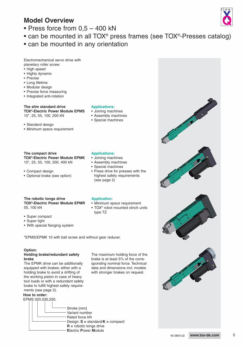
The compact driveTOX®-Electric Power Module EPMK10*, 25, 55, 100, 200, 400 kN
• Compact design• Optional brake (see option)
Applications:• Joining machines• Assembly machines• Special machines• Press drive for presses with the
highest safety requirements(see page 2)
The slim standard driveTOX®-Electric Power Module EPMS10*, 25, 55, 100, 200 kN
• Standard design• Minimum space requirement
Electromechanical servo drive withplanetary roller screw:• High speed• Highly dynamic• Precise• Long lifetime• Modular design• Precise force measuring• Integrated anti-rotation
Applications:• Joining machines• Assembly machines• Special machines
The robotic tongs driveTOX®-Electric Power Module EPMR55, 100 kN
• Super compact• Super light• With special flanging system
Application:• Minimum space requirement• TOX® robot mounted clinch units
type TZ
*EPMS/EPMK 10 with ball screw and without gear reducer.
Model Overview• Press force from 0,5 – 400 kN• can be mounted in all TOX® press frames (see TOX®-Presses catalog)• can be mounted in any orientation
Option:Holding brake/redundant safetybrakeThe EPMK drive can be additionallyequipped with brakes: either with aholding brake to avoid a drifting ofthe working piston in case of heavytool loads or with a redundant safetybrake to fulfill highest safety require-ments (see page 2).
The maximum holding force of thebrake is at least 5% of the corre-sponding nominal force. Technicaldata and dimensions incl. modelswith stronger brakes on request.
www.tox-de.com40.0804.02
How to order:EPMS 025.030.250.
Stroke [mm]Variant numberRated force kNDesign: S = standard/K = compact/R = robotic tongs driveElectric Power Module

6
B
R
M***K***
G W
ØF
ØH
ØV L A
TU
N
C
ØD
I J
A2
A1
XQl i n e -
www.tox-de.com 40.0804.02
Data sheetTOX®-Electric Power Module EPMS 10, 25, 55, 100, 200 kN
Dimensions
*Recommended operating range 5-100%**Specials on request.(colour, stroke, speed, ..)***Zero position of drive is the reference (marked) position + 3 mm****in thermal transient condition
Order no.
Type Stroke
Nomi-nalforce[kN] A A1 A2 B C D Ff7 G H I J K L M N R T U Vg6 W
Weightapprox.
kg
EPMS 010.030. 250 10 70 90 76 939 8xM8x16 60 50 10 30 15° 75° 20 M12x1,5 32 24 300 390 720 – – 21
EPMS 025.030. 250 25 70 90 76 1047 8xM8x16 60 50 10 30 15° 75° 28,5 M22x2 48,5 24 300 390 568 18 7 25
EPMS 055.030. 300 55 95 105 105,5 1218 8xM10x20 83 70 10 40 15° 75° 35 M30x2 60 34 316 456 678 26 7 43
EPMS 100.030. 300 100 115 130 122 1373 8xM12x25 98 75 15 50 15° 75° 36 M30x2 61 41 343 483 1316 26 7 72
EPMS 200.030. 300 200 145 – 146 1618 8xM16x25 125 100 18 70 15° 75° 46 M39x2 81 60 385 525 – – – 140
Specifications EPMS 010.030.250 EPMS 025.030.250 EPMS 055.030.300 EPMS 100.030.300 EPMS 200.030.300Mechanical
Rated force* push 10 kN 25 kN 55 kN 100 kN 200 kN
Rated force pull 3 kN 7,5 kN 16,5 kN 30 kN 60 kNStroke** 250 mm 250 mm 300 mm 300 mm 300 mm
Max. speed** 300 mm/s 220 mm/s 200 mm/s 200 mm/s 85 mm/sMax. short-termoverload
10% of rated force
Positional repeatabilityunder load****
< ± 0,01 mm
SensorsLoad cell 0,5 – 10 kN 1,25 – 25 kN 2,75 – 55 kN 5 – 100 kN 10 – 200 kNRated force 10 kN 25 kN 55 kN 100 kN 200 kNAccuracy < +/- 0,5 % of rated force,pressing
Resolver x x x x xResolution 0,0012 mm 0,0004 mm 0,0004 mm 0,0005 mm 0,0003 mmElectrical
Protection class Motor/drive IP54 (as component)
Mains supply see axis controller
Climatic conditions + 10 to + 40°C, from 40° C performance loss, max. 55° C; air moisture < 75%**, without condensation
For CAD files, please
visit us at
www.tox-de.com

7
A1B
UT
R
M***K***G W
ØF
ØHL
ØV A
X
N
ØD
ØC
P
ØY
A2
J I
XQl i n e -
www.tox-de.com40.0804.02
Dimensions
Data sheetTOX®-Electric Power Module EPMK 10, 25, 55, 100, 200, 400 kN
Optional with brake
for category 4 safety
requirements
*Recommended operating range 5-100%**Specials on request. (colour, stroke, speed, ..)***Zero position of drive is the reference (marked) position + 3 mm****in thermal transient condition*****EPMK 400 only with Axis Controller line-X available
Specifications EPMK 010.030.250 EPMK 025.030.250 EPMK 055.030.300 EPMK 100.030.300 EPMK 200.030.300 EPMK 400.030.300*****MechanicalRated force* push 10 kN 25 kN 55 kN 100 kN 200 kN 400 kNRated force pull 3 kN 7,5 kN 16,5 kN 30 kN 60 kN 400 kNStroke** 250 mm 250 mm 300 mm 300 mm 300 mm 300 mm
Max. speed** 300 mm/s 250 mm/s 200 mm/s 200 mm/s 85 mm/s 40 mm/s
Max. short-termoverload
10% of rated force
Positional repeatabilityunder load****
< ± 0,01 mm
SensorsLoad cell 0,5 – 10 kN 1,25 – 25 kN 2,75 – 55 kN 5 – 100 kN 10 – 200 kN 20 – 400 kN or
-20 – -400 kNRated force 10 kN 25 kN 55 kN 100 kN 200 kN 400 kNAccuracy < +/- 0,5 % of rated force,pressing
Resolver x x x x x xResolution 0,0012 mm 0,0004 mm 0,0004 mm 0,0005 mm 0,0003 mm 0,0015 mmElectrical
Protection class Drive IP54 (as component)
Mains supply see axis controller
Climatic conditions + 10 to + 40°C, from 40° C performance loss, max. 55° C; air moisture < 75%**, without condensation
Order No.
TypeStro-ke
Nomi-nalforce[kN] A A1 A2 B C D Ff7 G H I J K L M N P R T U Vg6 W X Y
Weightapprox.
kg
EPMK 010.030. 250 10 70 92 76 657 8xM8x16 60 50 10 30 15° 75° 20 M12x1,5 32 24 211 300 390 568 – – 24 59 22
EPMK 025.030. 250 25 70 92 76 657 8xM8x16 60 50 10 30 15° 75° 28,5 M22x2 48,5 24 211 300 390 568 18 7 24 59 26
EPMK 055.030. 300 55 95 120 105,5 761 8xM10x20 83 70 10 40 15° 75° 35 M30x2 60 34 245 316 456 678 26 7 28 60 46
EPMK 100.030. 300 100 115 156 122 854 8xM12x25 98 75 15 50 15° 75° 36 M30x2 61 41 280 343 483 750 26 7 28 62 78
EPMK 200.030. 300 200 145 170 146 973 8xM16x25 125 100 18 70 15° 75° 46 M39x2 81 60 327,5 385 525 838 – – 52 94 154
EPMK 400.030. 300 ±400 250 276 250 1260 8xM24x40 200 150 20 100 30° 60° 60 M64x2 120 85 525 432 552 1074 – – 60 114 543
For CAD files, please
visit us at
www.tox-de.com

8
C M***K***
G
Q
X
ØY
C4
C3
D2
C1
D1C2
E2
E1 AN
W
FLF
4F
3
F1F2
ØH
ØJ
ØV
RT
UB
P
A1A2A3
XQl i n e -
www.tox-de.com 40.0804.02
Data sheetTOX®-Electric Power Module EPMR 55, 100 kN
Dimensions
*Recommended operating range 5-100%**Specials on request. (colour, stroke, speed, ..)***Zero position of drive is the reference (marked) position + 3 mm****in thermal transient condition
Order no.Type Stroke K L M N P Q R T U Vg6 W X Y
EPMR 055.030. 100 18 M24x1,5 37 24 245 83 182 262 484 22 6 28 60
EPMR 100.030. 100 17 M24x1,5 36 30 274 120 218 298 565 22 6 28 62
Order no.
Type Stroke
Nomi-nalforce[kN] A A1 A2 A3 B C C1 C2 C3H7 C4H7 D1 D2 E1 E2 F F1±0,02 F2 F3 F4 G H J
Weightapprox.
kg
EPMR 055.030. 100 55 95 120 105,5 39 567 27 13 9 14 14 15 21 60 62 92,5 45 62,5 6 9 4 40 28 38
EPMR 100.030. 100 100 115 144 121,5 57 668,5 33 17,5 11 14 14 17 25 85 84 115,5 58 75,5 6 10 4 50 33 68
The tightly toleranced (H7) keywayson the mounting flange provide forprecise alignment of the drive withrespect to the direction of travel.The height and position of the drivecan be precisely adjusted usingspacer plates and keys.
Specifications EPMR 055.030.100 EPMR 100.030.100MechanicalRated force* push 55 kN 100 kN
Rated force pull 16,5 kN 30 kN
Stroke** 100 mm 100 mm
Max. speed** 120 mm/s 120 mm/s
Max. short-term overload 10% of rated force
Positional repeatability underload****
< ± 0,01 mm
SensorsLoad cell 2,75 – 55 kN 5 – 100 kNRated force 55 kN 100 kN
Accuracy < +/- 0,5 % of rated force,pressing
Resolver x xResolution 0,00025 mm 0,0003 mm
ElectricalProtection class Drive IP54 (as component)
Mains supply see axis controller
Climatic conditions + 10 to + 40°C, from 40° C performance loss, max. 55° C;air moisture < 75%**, without condensation
For CAD files, please
visit us at
www.tox-de.com

9
XQl i n e -
www.tox-de.com40.0804.02
Applications:• Clinching• Clamping• Marking• Robot Applications
Advantages:•Part accessibility•Top loading•Clamping and Clinching at thesame time
TOX®-Electric PowerKurver EPC 90 kN
Accessories such as for TOX®-PowerKurver type KK are possible(see TOX®-PowerKurver catalog).
Ordering example:EPC 90.090.000
Version numberOpening anglePress force (kN)Electric Power Curver
Servo-Drive-Unit with planetary rollerscrew in combination with our provenTOX®-PowerKurver cam activatedpress design. The large openingangle allows for easy access to too-ling.
• Self-locking• Long lifetime• Freely programmable opening
angles, up to 90°.
The Servo Spindle in operation
Robot guided clinching tongsEPMR 55 used in TOX®-Robotic tongs TZ for joining sheet metal
EPMR 55
Option:Terminal box for starting thecompensating slide and thespray lubrication equipment, andmanual initiation for spraying alubricant on to the joining area, ifrequired.
TOX®-Robot tongs TZ (see brochure: TOX®-Tongs)
Option:Robot coupling
Application:Metal joining withTOX®-Round Joint(see brochure: TOX®-Joining Systems)

10
XQXQ
Ql i n e -
Xl i n e -
l i n e -
www.tox-de.com 40.0804.02
Ethernet
Servo motor
Load cell signal
Axis-Controller (Ill.: line-X)
Fieldbus
I/O
Resolver signal
Option:24 V DC brake
PC/Laptop or IPCfor operating andprocess monitoring
Control for parameter settingand commissioning
TOX®-Axis-Controllerline-Q
TOX®-Axis-Controllerline-X
TOX®softWare
EthernetInterbus/ServiceNet/Profibus
RS 232/485PLCNETWORK
The line-Q and line-X idea
Between the servo drive and the servicing, parameter setting and visualization, there is always an axis-controller.The functions and interfaces available depend on the type of the axis-controller.
For the TOX®-ElectricDrive, one mayselect between two single axis con-trollers, line-Q or line-X. Both linesare identical in their mechanicaldesign and differ only with regards tothe number of features.
Complete program line-Q• Short lead time• Limited in the number of functions
and customer interfacesThe first choice if the extensivelist of functions is sufficient.
Complete program line-X• Nearly unlimited number of
functions with custom interfaces possible.
The best choice if the extensivelist of functions is already suffi-cient or can be expanded by theTOX® service experts.
StandardData bus • RS 232 / RS 485
• Ethernet TCP / IPFieldbus • Profibus-DP
OptionalInterbus instead of Profibus
Other Fieldbus available over Gateway, e.g. DeviceNet,ControlNet, Ethernet IP
Analog0-10 V, alternative to Profibus
Digital8 inputs / 8 outputsexpandable to 32
StandardData bus • Ethernet TCP/IP Fieldbus • Profibus-DP
• CanOPEN
OptionalOther Fieldbus available over Gateway, e.g. Interbus, DeviceNet,ControlNet, Ethernet IP
Analog0-10 V; two available with one free
Digital8 inputs / 4 outputsexpandable to 255
Spindle (Ill.: EPMK)

11
XQl i n e -
www.tox-de.com40.0804.02
TOX®-Axis-Controller line-Q and line-X
Configuration and Programmingwith the TOX®
SoftWareAll parameters, configuration and pro-gram functions residing inside thecontroller will be accessed with thesoftware module TOX®-Worx in thesoftware package TOX®
softWare. TheTOX®
softWare is delivered with eachTOX®-ElectricDrive. The followingsystem requirements are necessaryto access the TOX®
softWare in the axiscontroller:TOX®
softWare in the axis controller:• (Industrial) PC (Pentium III)• Operating system WIN2000 or
higher • Java Runtime
The circuit diagrams are includedwith the operating manuals. Onrequest, we can provide an info CDincluding wiring examples, TOX®
soft-
Ware, PLC building blocks and theoperating manual immediately afterreceipt of the order.
TOX®-Axis-Controller:the central intelligenceBoth freely programmable axis con-trollers are single axis controllers withintegrated logic and servo amplifier.They control and monitor all functionsof the TOX®-ElectricDrive system.Advantages include the highly dyna-mic processing of pressing programsand fast reaction to variations in theprocess. During and after production,the process data can be taken fromthe controller for further processing ordocumentation.
Common Characteristics:• Faster commissioning,
Plug and Work• Extensive programming and
diagnostic functions• Parameter programming of
processes (online and offline)• Pre-configured and pre-calibrated• Maintenance-free• Display and monitoring of force-
travel progressions• Graphical process analysis• Display of process results including
status, date and time stamp• Target position with monitoring of
force limits• Target force with monitoring of
position limits• Window monitoring• Sequential control• Run according to PLC standard
values• PLC function blocks e.g.
Siemens S7• Deflection compensation• Abstract from the standard function
library:- Force and/or travel controlled
commands- Functions for process control and
process data recording- Graphical displays
- Processing of input signals as wellas definition and setting of output signals
- Taring and continuous monitoringof force sensors
• Quality data management overEthernet and Fieldbus
• Commissioning function without PLC
• Input and allocation of calibration values of the force sensors
• Integration of external force sensors(DMS and 0-10 V are possible)
• Functional test of load cells• Highest safety category possible
(see page 2)• Axis controller and ballast resistor
can be installed in any applicable standard enclosure
• Electric connections are provided with plugs
• Integrated overload functions for motor and servo amplifier
• Electrical isolation betweencontroller and amplifier
• 3-cable technology• Protection degree IP20, can be
extended to IP54• Compact design with direct AC
supply and integrated resolver andmotor connection
• For spindle operation, includingprocess monitoring a PC is not required

12
Ql i n e -
www.tox-de.com 40.0804.02
TOX®-Axis-Controller line-Q
Status displays LED
Status displaysLED I/O
X2-com-TerminalProgramming port
COM 2/3 RS 232(e.g. barcode input)
X10 Profibus/Interbus
X7 Ethernet
X6 I/O Expansion
X4/X5 Encoder input
X13/X14 Active/passivetransducer
X3 Encoder output
X1 Servofeedback
X50/X51 DigitalInput/Output
X40 Category 3 safety
X20 Motor plug
X31 Ballast resistorX30 AC Input
Complete panel in IP54.Customer specific solutionspossible on request.
Special solutionsSpecial properties of line-Q• Stores last 1000 process data sets• Memory for about 25 processes
(for TOX® standard workflows)• Digital force regulation with
0.5 ms sample rate of 0,5 ms • Four controllers are allocated
according to spindle sizes and arespecially matched to their capacityranges
• Customized interfaces are possible within a limited scope
General data and installation requirementsOperating conditionsCircuit type with grounded star-circuit unlimited use
IT-net Follow instructions for special measures!
StandardsConformity CE Low voltage directive (73/23/EWG)
Approvals UL 508C Power Conversion Equipment (File-No. 32659)
EnclosureEnclosure type IP20 not in the connecting area of the
motor side connectors.Contact protectionaccording to type 1
Climatic conditionsOperation* IEC/EN 60721-3-3 3K3 (+5 ... +40°C)
Derating of rated output current +40 ... +60°C: 1,5%/°C
air moisture max. 95%, without condensation*Attention: In case of an installation at 1000 m above sea level the reduction of the nominal current will be 15%/1000 m.
13
125,6118
55,5
7
2,5
10,5
53,257
273,5
243,
9
277,
4
285
310,
8
206,5
+ UB
Rext
line-Q
X31
X10
X11/X12
X40
X2
X7
X13
X1
X20I/O
X50-52
Ql i n e -
www.tox-de.com40.0804.02
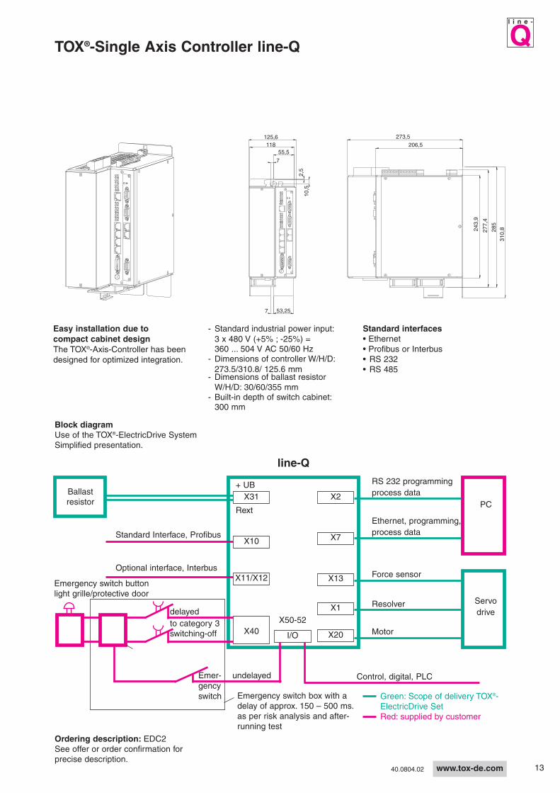
TOX®-Single Axis Controller line-Q
Green: Scope of delivery TOX®-ElectricDrive SetRed: supplied by customer
Block diagramUse of the TOX®-ElectricDrive SystemSimplified presentation.
Ballastresistor
Emergency switch box with adelay of approx. 150 – 500 ms.as per risk analysis and after-running test
Emergency switch button light grille/protective door
PC
Servodrive
Ethernet, programming,process data
Motor
Control, digital, PLCEmer-gencyswitch
Resolver
RS 232 programmingprocess data
Standard Interface, Profibus
Optional interface, Interbus
Easy installation due tocompact cabinet designThe TOX®-Axis-Controller has beendesigned for optimized integration.
- Standard industrial power input:3 x 480 V (+5% ; -25%) =360 ... 504 V AC 50/60 Hz
- Dimensions of controller W/H/D:273.5/310.8/ 125.6 mm
- Dimensions of ballast resistor W/H/D: 30/60/355 mm
- Built-in depth of switch cabinet:300 mm
Force sensor
Standard interfaces• Ethernet• Profibus or Interbus• RS 232• RS 485
delayed
undelayed
to category 3switching-off
Ordering description: EDC2See offer or order confirmation forprecise description.

14
Xl i n e -
www.tox-de.com 40.0804.02
TOX®-Axis-Controller line-X
Special solutions
Complete panel in IP54. Custo-mer specific solutions possible onrequest.
By plugging the axis-controller to oroff the mounting base, it can bequickly connected or replaced.
The plug-in system of the modulesmakes them easy to select and tochange:• Safety• Bus (communication)• Intelligence
Special properties of line-X• Storage of the last 500 process data
records• Digital force regulation with
sampling rate of 1ms• Memory for about 270 processes
(for TOX® standard workflows) • Six controllers are allocated
according to spindle sizes and arespecially matched to their capacityranges
• Customized interfaces are generallypossible
Pluggable modulesPluggable Axis controller Pluggable I/O connections
Mounting socket
Axis controller
Mains filter
Profibusmodule
EthernetTCP/IP module
Memorymodule
Safety module
Motorconnection
Basic applianceMainsconnection
Digital I/O
Diagnosticinterface
Resolver-connection
Analog Inputs/Outputs
CANonBOARD

15
Xl i n e -
www.tox-de.com40.0804.02
Functions and possibilites of line-X
General data and installation requirements
Exclusive properties of line-X• Integrated PLC functionality,
IEC 61131• Envelope curve monitoring• Controlling remaining bottom
thickness for clinching (quality dimension X)
• Integration of external distancesensorics
• All modules are pluggable• Customized fault diagnostics are
possible• Customized functions are possible
Current volume of special functionlibraryProcess jumps: process calling, sub-process calling• With process jumps it is possible to
define jumps into other processes during and/or at the end of aprocess.
Spindle data• By adding this function, you can
change the spindle data “on the fly”while the process is running. At the end of the process, the spindle data will be reset to the default value.This gives you the possibility to work with additional force sensors on one spindle.
Stopping the process• By adding this function, the process
is stopped. This is useful in combi-nation with the “conditional check”function.
Conditional check function (start-,target-, end condition)• Based on a selectable source (IO,
Fieldbus, variable). This function gives you the possibility to define multiple conditional targets within aprocess.
Set and evaluate integer and/or realvariables• This function is used to define an
integer and/or real variable for the “conditional check” function.
Operating conditionsCircuit type with grounded star-circuit unlimited use
IT-net Follow instructions for special measures!
StandardsConformity CE Low voltage directive (73/23/EWG)
Approvals UL 508C Power Conversion Equipment (File-No. 32659)
EnclosureEnclosure type EN 60529 IP20 not in the connecting area of the
motor side connectors.NEMA 250 Contact protectionaccording to type 1
Climatic conditionsOperation* IEC/EN 60721-3-3 EN 50178 3K3 (-10 ... +55°C)
Derating of rated output current +45 ... +55°C: 2,5%/°C
air moisture max. 85%, without condensation*Attention: In case of an installation at 1000 m above sea level the reduction of the nominal current will be 15%/1000 m.

16
line-X
X105
MXI1
MSI
MMI
MXI2
X3
X7
X105I/O
X4, X5
a
6015
Xl i n e -
www.tox-de.com 40.0804.02
green: Scope of delivery TOX®-ElectricDrive Setred: supplied by customer
Blocks diagramUse of the TOX®-ElectricDrive-System.Simplified diagram.
Ballastresistor
Emergency switch box with adelay of approx. 150 – 500 msas per risk analysis and after-running test
Emergency switch button light grille/protective door
PC
Servodrive
Ethernet, programming,process data
Motor
Control, digital, PLCEmer-gencyswitch
undelayed
Resolver
Force sensor
Standard Interface, Profibus
approx. 150-500 msdelaySafety category 3
TOX®-Axis-Controller line-X
Size of the TOX®-ElectricPower Module
Dimensions a(mm)
Weight(kg)
EPMx 010 90 5,3
EPMx 025EPMx 055EPMx 100
120 8,1
Size ofthe TOX®-Electric PowerModule
Dimensions (mm)Wei-ght(kg)
a b b1 b2 e c1 d g mEPMx 200EPMx 400
206 606 556 630 294 170 585 6,5 12,5 26,5
Mounting dimensions Mounting plate Mains filter for EPM x 10-100
- Standard industrial power input: 3 x 180 - 550 V (+0% ; -0), Nominal power at 400 V AC 50/60 Hz- Dimensions of ballast resistor W/H/D: 30/60/355 mm- Built-in depth of switch cabinet: 400 mm

17
XQl i n e -
www.tox-de.com40.0804.02
Worx Diagram line-X
Worx-Project management line-X
CommissioningAn online mode enables the user tomonitor all controller functions andI/O in real time for commissioningand troubleshooting purposes.
Curve mappingI/O DisplayJog function
ProgrammingThe process cycle is configured byselecting process specific functionblocks from a menu, building a presssequence. No CNC code program-ming knowledge is required.
Click on the Menu function blockEnter the required parametersStart the processControl the process
TOX®SoftWare Facts and Features for line-Q and line-X
�� User friendly�� Easy configuration�� Integrated documentation�� Designed for touch screen use
�� Platform independent�� Supports all common interfaces�� Several user levels
Project environmentThe WORX-Module has pre-configu-red, ready to use press functionblocks which can be customized tothe individual application. A dialogbased project-wizard will aid in theinitial setup and assist in the projectlayout. Projects can be saved andcopied as templates for future use.
The Windows based user interfacehas a familiar look and feel enablingquick and easy navigation throughthe projects. The Explorer-style menulayout supports easy administrationof press programs and file handling.
Abstract from the function library line-X
TOX®SoftWare WORX
The TOX®SoftWare consists of the pro-
grams: Server (connection from thePC to the axis controller), WORX andHMI.
TOX®SoftWare is a new, interactive
Software Suite with completely inte-grated controls and monitoring functi-ons specifically designed for all appli-cations.
The user will be able to quickly defineand configure new projects withoutthe knowledge of any programminglanguage. Operating interface andsoftware are programmed by TOX®
and may be adapted in conformitywith customer’s request.

18
XQl i n e -
www.tox-de.com 40.0804.02
TOX®SoftWare HMI
• Adaptable screen surface• Messages can be freely defined
(errors, information, status, etc.)• Manual / Automatic screen• Diagnostic screen with logbook• Process data export in Excel-compatible CSV
format for quality management• Counter (total, IO ,NIO, maintenance intervals)• Protected against unlicensed change access by
authorization• Special screens with additional information can be
integrated (e.g. temperature indicators, travelmeasuring systems and the like)
• Backup of all parameters by pressing a button
Manual operation picture line-Q
TTM(TOX® Touch Menue) line-Q
Diagnostic module line-Q
HMI-communication environment(HMI = Human-Machine-Interface)The TOX®
SoftWare includes an HMI for the operator tocontrol and visualize the process. The user platformcan be adapted by the user. It is also possible toconfigure a data export in this part of the software.

19
Ql i n e -
www.tox-de.com40.0804.02
Graphics module line-Q
Sequence module line-Q
Process data export in graphics module line-Q
TOX®SoftWare HMI with line-Q
Process control using the window technique
Monitoring of a force/travel progression ofa process with defined windows.
+ An almost unlimited number of force/travelwindows can be defined.
Sequential control – expanded process admini-stration and simplified conversion scenario
+ Piecepart-specific parameter change by pressing a button and selection of another sequence
+ Maximum number of processes limited only by thehard drive capacity
+ Dynamically controlled process flow with IO/NIO statement
+ Highly efficient manual workplaces thru single cycle control possibility

20
Xl i n e -
www.tox-de.com 40.0804.02
Clinching module with envelope curve line-Q
Pressing module process parameter line-Q
Clinching module process parameter line-Q
MonitoringThe HMI collects the complete force/travel diagramsand evaluates them with the help of freely program-mable windows and/or envelope curves. The valuescan be zoomed and displayed in different ways.SPC Data can be archived (SPC: statistic processcontrol).
TOX®SoftWare HMI with line-X
Simple teach-in mode+ Automatic teaching of the processes and the force
limits in the target window and the envelope+ no programming, just parameter setting+ automatic scaling of diagrams
Process monitoring using envelope curvesThe envelope curve determines by two limit curvesthe path of the force/travel progression+ Full monitoring within the set point and target
windows, i.e. the force/travel characteristics curvecan not fall outside the upper and lower limits
+ Selection possibility!For curves deviating from the envelope, theseoptions apply:
process will continue until targetwindow is reachedstop process
Pressing module for highly flexible pressingprocedures+ Cockpit function due to complete parameter setting
on one screen+ High precision possible, for example, by the
integration of different piecepart specific deflectionvalues in the process flow
+ High repetitive accuracy, for example, by thepossible compensation of dimensional fluctuations of piecepart lengths
+ Complex process flows can be realized(several jump function, sub-process calling etc.)
Clinch module for the modern sheet metaljoining technologyPrecise control of the quality dimension X (remai-ning bottom thickness after the clinching process) inconsideration of the machine deflection. Irregulari-ties in production (fluctuations in sheet metal thick-ness, fluctuations in surface condition ...) could other-wise cause fluctuations of the dimension X.
+ active stabilization of variancestechnical optimum achieved with an accuracy of± 0,04 mm
+ the X dimension is assured independent ofmaterial combination and properties
Point diameter
Controldimension "X"Controldimension "X"
ePunch sideDie side

21
XQl i n e -
www.tox-de.com40.0804.02
Control Options for line-Q and line-X
IP54 enclosure
For axis controller package, includingfan or cooling unit. Specificationsaccording to TOX® Standards. Specialexecutions available on request(Example see picture page 12 and14).
Safety Controls
All the following control variants aretype-examination tested.
Basic Controls:
• Cycle initiation over 2-hand buttons.Both switches must be held down during the complete cycle.
• Visualization over IPC with swivel arm to be mounted on pressframe with flange selectively from aboveor below.
Light Curtain Controls:
• Safety guarding and controlling versionTwo operating modes are available:1. The light curtain has no control-
ling function. Cycle initiation over 1-hand switch or foot switch.
2. The light curtain has a controlling function. Cycle initiation after endof light curtain interruption(so-called Talot control)
Special executions (on request):• Software integration of external
components, e.g. sensors fortemperature, travel, etc.
• Activation of additional motions, e.g.for a sliding table, a guarding door, etc.
Industrial PC from TOX®:the sturdy alternative to usual PC systems
Options to Basic Controls:• Function safe return stroke.
The return stroke of a press takes place automatically after completingthe press cycle. The switches do nothave to be held down during the return stroke.
• Function safe speed. The drive extends with a maximum speed of 10 mm/s. The controls can beactivated with a 1-hand switch or foot switch.
Control with protective door:• Cycle initiation by 1-hand switch or
foot switch• The pressing process is only started
if the protective door is closed
Execution IPC with stainlesshousing, rack mount
version
High speed IPC in panel mount version Terminal: embeddedIPC rack aspanel mount
Touchscreen 12.1 inch TFT (SVGA) 12.1 inch TFT (SVGA) 17 inch TFT (SXGA) 12.1 inch TFT (SVGA)
Operating system Windows XP TOX® Linux
Software TOX®softWare TOX®
softWare Terminalwith reduced function, forline-Q only
Mass storage 40 GB HD 512 MB CF Card
Interfaces 2x USB (one front con-nection), 1 x Ethernet10/100 Base- T RJ-45,2 x PS/2,1 x COM1 RS232,1 x VGA-CRT, 1 x LPT
2 x USB (one front connection)1 x Ethernet 10/100 Base- T RJ-45
2 x PS/21 x COM1 RS232
1 x VGA-CRT1 x LPT
4 x USB (two front connections)
1 x Ethernet 10/100 Base-T RJ-45
Ambient temperature +5°C...+40°C +5°C...+45°C +5°C...+50°C
In contrast to a terminal, the Industri-al PC (IPC) allows additional pro-grams to be installed.
Particularly ruggedbased on solid statecircuitry. Offline opera-tion is not possiblewith this terminal.

22
XQl i n e -
www.tox-de.com
For the re-calibration of the TOX®-ElectricPower Module. The intervalfor the re-calibration is fixed by cus-tomer’s quality management.
Calibration equipment type ZKEIncludes:- Precision force sensor
10, 50, 100 or 200 kN- Digital display unit- Shockproof power cord- Calibration certificate- Aluminum case
Planning and design of completepresses and special machines.
TOX® PRESSOTECHNIK helps yousolve your production demands withthe application of specific solutionsmade with components from ourstandard product line.
Realization of electro-mechanic pres-ses of utmost safety level (see page2) and tested by the GermanEmployer’s Liability Insurance Asso-ciation.
ApplicationsFrom the TOX building blocks to special machines
Possible on request.
Accessories
Grease gun for re-greasing the TOX®-ElectricDrive Systems
Greasing intervals and amountaccording to the manual,suitable for 400g TOX®-Spindlegrease cartridge.
It is a must for the reliable operationof the spindle.Order no.: ZFP
400g TOX®-Special greasecartridgeOrder no.: ZFE
Automatic lubrication forTOX®-ElectricPower Module
40.0804.02
TOX®-Press series PCWith 2-column ram guide, EPMK100 with brake, protective hood withexhaust fan, safety 2-hand controls,function “safe direction” with opera-tor guarding and touch screen IPCwith TOX®
softWaresee picture page 3

23
XQl i n e -
www.tox-de.com
Applications
TOX®-Press series MBwith 2-column ram guide, baseUUM, EPMK 55 with brake, safetycontrol with protective door and1-hand key with function “safespeed” for inching operation withopen protective door andTOX®
softWare
TOX®-Automatic stationC-frame type CEJ with CERstand, EPMR 55, TOX®-Clinchingtools and TOX® lube sprayequipment
TOX®-Press series MAGWith 4-column ram guide,EPMK 100 with holding brake,slide table with locking cylinder,UUM of welded construction,safety control with protectivedoor and 1-hand key or footpedal, with touch screen IPCwith TOX®
softWare
TOX®-Automatic stationC-frame type CEB with CER stand,EPMK 55 positioning cylinder forCEB, EPMK 55 for pressing andpulling operation, EPMK 10 pre-load axis with external force sensor
TOX®-Press series PCWith 2-column ram guide, forpressing and pulling operation,EPMK 400 with brake, protectivehood with exhaust fan, safetycontrols with function “safespeed”, stroke initiation via1-hand key or foot pedal
TOX®-Automatic stationseries CMBWith linear guided ram mountedin the C-frame, UUM table,EPMK 100, control for automaticoperation with touch screen IPCwith TOX®
softWare
40.0804.02

24
Our Worldwide Sales and Service Network
TOX® PRESSOTECHNIKRiedstraße 4D-88250 WeingartenTel. +49 (0) 7 51 / 50 07-0Fax +49 (0) 7 51 / 5 23 91E-Mail: [email protected]
GMBH &CO. KG
40.0804.02 Subject to technical alternations.
TOX®-Production
Systems
TOX®-Fastener-
Insertion
TOX®-Piercing
and Marking
TOX®-Tongs
TOX®-Joining-
Systems
TOX®-Controls,
TOX®-Monitoring
TOX®-Presses
TOX®-FinePress
TOX®-ElectricDrive
TOX®-PowerKurver
TOX®-Powerpackage
Product Range