electricity and magnetismchunghuastpm.weebly.com/.../chapter13_capacitors.pdf1 13 capacitors...
TRANSCRIPT

1
13 Capacitors
ELECTRICITY AND MAGNETISM
2
Contents 18.1 Capacitance 18.2 Parallel plate capacitors 18.3 Dielectrics 18.4 Capacitors in series and in parallel 18.5 Energy stored in a charged capacitor 18.6 Charging and discharging of a Capacitor
3
Objectives a) define capacitance (C = Q/V) b) describe the mechanism of charging a
parallel plate capacitor c) use the formula C = Q/V to derive C =
0A/d for the capacitance of a parallel plate capacitor
d) define relative permittivity r (dielectric constant)
e) describe the effect of a dielectric in a parallel plate capacitor
4
Objectives f) use the formula C = r 0A/d g) derive and use the formulae for
effective capacitance of capacitors in series and in parallel
h) use the formulae U = ½ QV, U = ½ Q2/C, U = ½CV2 (Derivations are not required.)
i) describe the charging and discharging process of a capacitor through a resistor
5
Objectives j) define the time constant, and use the
formula = RC k) derive and use the formulae
and for charging a capacitor through a resistor;
Objectives
l) derive and use the formulae , for discharging a capacitor through a
resistor m) solve problems involving charging and discharging of a capacitor through a
resistor. 6
7
13.1 Capacitance
8
Defining Capacitors
Short-term Charge Stores

9
Capacitors Device for storing electrical energy which can then be released in a controlled manner A capacitor consists of 2 conductors of any shape placed near each other without touching The region between the 2 conductors is usually filled with an electrically insulating material called a dielectric
10
Capacitors Symbol in circuits is It takes work, which is then stored as potential energy in the electric field that is set up between the two plates, to place charges on the conducting plates of the capacitor Since there is an electric field between the plates there is also a potential difference between the plates
11
Capacitors We usually talk about capacitors in terms of parallel conducting plates They in fact can be any two conducting objects
12
Capacitors When a capacitor
each of its 2 plates carries the same magnitude, q, of charge the potential of the +q plate exceeds that of the q plate by an amount V
The charge q and potential difference V are related by Q = C V where C is the capacitance The SI unit for capacitance is farad (F), where 1 farad = 1 coulomb/volt
13
Dielectric Constant If a dielectric is inserted between the capacitor plates, the electric field E inside the capacitor is weaker than the field E0 inside the empty capacitor, assuming the charge on the plates is unchanged This reduction of the field is described by the dielectric constant , defined as k = E/E0
( or Er= E/E0) 14
Capacitance of Parallel-Plate Capacitor
The capacitance of a parallel-plate capacitor without a dielectric is But if a dielectric is placed between the plates, Thus air or vacuum has = 1
ACd0
0 ACd
16
Capacitance of Capacitor
Capacitance C depends on capacitor on dielectric type NOT on capacitor q or potential difference V
Since > 1, capacitance C increases when a dielectric is present
17
Electric Energy Storage Electric energy can be stored in capacitors

18
Key Ideas - Capacitors Capacitors are short-term charge stores. They act as electrical springs. There are a number of electrical parameters (measurements of properties) that are of interest to the electronics engineer. These include working voltage, leakage current, and temperature coefficient. These are written in data tables
19
Comparison to a Battery
Property Battery Capacitor
Charging time Long (hours) Short (fraction of a
second)
Number of charge and discharge cycles
1000 1500 at best Billions of times
Charge held Many coulombs Micro coulombs
How energy is stored Chemical reaction Electric field
analogy Fuel tank Electrical spring
20
Example
21
Capacitor Sandwich Construction
Two metal plates Separated by insulating material
22
Swiss Roll Construction
23
Metal Plates + Dielectric
Capacitors consist of two metal plates separated by a layer of insulating material called a dielectric.
24
Types of Caps
25
Types of Caps
There are two types of capacitor, electrolytic and non-electrolytic. Electrolytic capacitors hold much more charge Electrolytic capacitors have to be connected with the correct polarity, otherwise they can explode.

26
Schematic Symbol
The symbol for a capacitor is shown below:
27
Comparison of Types
Advantages:
High capacitance Can have high working voltages.
Advantages: Do not lose charge Polarity does not matter Stable up to 106 Hz (or more)
Disadvantages: Polarity important High leakage current Not stable above 10 kHz Can be damaged by AC
Disadvantages: Low capacitance
28
Numerical Parameters A working voltage is given. If the capacitor exceeds this voltage, the insulating layer will break down and the component shorts out. The working voltage can be as low as 16 volts, or as high as 1000 V. Leakage current means that the capacitor does not hold its charge indefinitely. A certain amount of current leaks across the dielectric. This is most marked in electrolytic capacitors. Temperature coefficient. The value of a capacitor can change quite markedly with different temperatures.
29
Leakage In an electrolytic capacitor there has to be a current to maintain the aluminium oxide layer. This is about 1 mA. Over a period of time the charge leaks away. This is called the leakage current. Also it is important that the polarity of the capacitor is correct, otherwise the aluminium oxide layer is not made and the component will conduct. The resulting heating effect can result in the capacitor exploding.
30
Working Voltage
All capacitors have a maximum working voltage. All insulators have a maximum voltage at which they will retain their insulating properties. The breakdown voltage is quoted in units of volts per metre, so it is actually an electric field.
31
Working Voltage
The breakdown voltage of air is 3000 V/mm, so a 5 mm gap will insulate up to 15 000 V. The actual voltage at which the breakdown occurs depends on the thickness of the material.
32
Working Voltage
The thinner the material, the lower the voltage that is needed before sparking will occur. If sparking occurs over a dielectric, then a hole will be burned in the dielectric and that is the end of the useful life for the capacitor.
33
Temperature Coefficient Capacitors, especially electrolytic, can lose their capacitance, i.e. hold less charge, when they get hot. The decrease in capacitance can change the characteristics of the circuit so much that it will not work properly. Therefore it is essential that the temperature in which the circuit is going to operate at is taken into consideration when designing a circuit and choosing the components.

34
Temperature Coefficient
Can be tested 35
Temperature Coefficient
From this graph we can see that: Mica capacitors are very stable with temperature. Ceramic bead capacitors have a linear relationship. Other types of capacitor have a temperature at which their capacitance is at a maximum. It falls away either side of the optimum.
36
How Capacitors Work When connected to a potential difference (e.g. a battery), the battery tries to push electrons through the wire away from its negative terminal.
complete circuit, you get a flow of electrons to the plate i.e. you get a current without a complete circuit, but only for a short period of time.
37
What happens next? As the electrons (the charge) build up on the plate, 2 things happen: 1. The plate becomes more negative and so becomes less attractive to the electrons, so the flow of electrons gradually reduces which means the current gradually reduces. 2. The electrons in the other plate are repelled by the build up of electrons in the first plate. So they move off the second plate. The electrons leaving the second plate complete the circuit.
38 39
If you plot a graph of the potential difference across the plates against charge stored on the plate you find:
V
Q
40
How it Works Basic Configuration
Battery
Bulb Capacitor
41
Capacitance As charge builds up, so does the pd across the plates Charged stored is directly proportional to the potential difference across the plates. Also, if then, V Q, Where Q = Charge in coulombs Q / V = a constant. Therefore C = Q / V We call the constant which relates the two, C, the capacitance because it is
- the capacity of the plates to store charge. Capacitance is measured in farad, F.
42
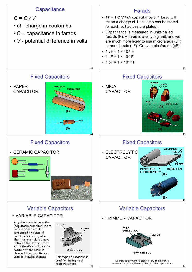
Capacitance C = Q / V
Q - charge in coulombs C capacitance in farads V - potential difference in volts
43
Farads 1F = 1 C V-1 (A capacitance of 1 farad will mean a charge of 1 coulomb can be stored for each volt across the plates). Capacitance is measured in units called farads (F). A farad is a very big unit, and we are much more likely to use microfarads ( F) or nanofarads (nF). Or even picofarads (pF) 1 F = 1 × 10⁻⁶ F 1 nF = 1 × 10⁻⁹ F 1 pF = 1 × 10-12 F
44
Fixed Capacitors
PAPER CAPACITOR
45
Fixed Capacitors
MICA CAPACITOR
46
Fixed Capacitors
CERAMIC CAPACITOR
47
Fixed Capacitors
ELECTROLYTIC CAPACITOR
48
Variable Capacitors VARIABLE CAPACITOR
A typical variable capacitor (adjustable capacitor) is the rotor-stator type. It consists of two sets of metal plates arranged so that the rotor plates move between the stator plates. Air is the dielectric. As the position of the rotor is changed, the capacitance value is likewise changed. This type of capacitor is
used for tuning most radio receivers.
49
Variable Capacitors
TRIMMER CAPACITOR
A screw adjustment is used to vary the distance between the plates, thereby changing the capacitance.

50
Color Codes
Although the capacitance value may be printed on the body of a capacitor, it may also be indicated by a color code. The color code used to represent capacitance values is similar to that used to represent resistance values. The color codes currently in use are the Joint Army-Navy (JAN) code and the Radio Manufacturers' Association (RMA) code
NOT IN EXAM
51
Color Codes
For each of these codes, colored dots or bands are used to indicate the value of the capacitor. A mica capacitor, it should be noted, may be marked with either three dots or six dots. Both the three- and the six-dot codes are similar, but the six-dot code contains more information about electrical ratings of the capacitor, such as working voltage and temperature coefficient.
52
Color Codes
The capacitor shown in the above figure represents either a mica capacitor or a molded paper capacitor. To determine the type and value of the capacitor, hold the capacitor so that the three arrows point left to right (>). 53
Color Codes
The first dot at the base of the arrow sequence (the left-most dot) represents the capacitor TYPE. This dot is either black, white, silver, or the same color as the capacitor body. Mica is represented by a black or white dot and paper by a silver dot or dot having the same color as the body of the capacitor. The two dots to the immediate right of the type dot indicate the first and second digits of the capacitance value
54
Color Codes
The dot at the bottom right represents the multiplier to be used. The multiplier represents picofarads. The dot in the bottom center indicates the tolerance value of the capacitor
55
Color Code - Caps
56
Color Code - Example
57
Reading Color Code Step 01 Hold the capacitor so the
arrows point left to right
Read the First Dot
Read the second digit dot and apply it to the first digit.
Read the multiplier dot and multiply the first two digits by multiplier (Remember that the multiplier is in picofarads).

58
Reading Color Code Step 02 Lastly, read the tolerance dot.
According to the left coding, the capacitor is a mica capacitor whose capacitance is 9100 pF with a tolerance of 6%.
59
Ceramic Capacitor Color Code
60
Calculate the Values
61
Calculate the Values
62
13.2 Parallel-plate capacitors
63
Parallel-plate Capacitors made of two plates each of area A (the
plates are separated by a distance d.
64
Parallel-plate Capacitors The electric field is the sum of the electric
65
Parallel-plate Capacitors

66
Parallel-plate Capacitors
67
Parallel-plate Capacitors
The electric fields outside the plates cancel out.
68
Parallel-plate Capacitors
The electric fields outside the plates cancel out. Make the outside fields disappear.
69
Parallel-plate Capacitors The electric fields between the plates add.
70
Parallel-plate Capacitors The charges move to the inside of the plates.
Move the + and symbols toward the center.
71
Parallel-plate Capacitors
The electric field inside is uniform. The electric field outside is small.
72
Parallel-Plate Capacitors Assume electric field uniform between the plates, we have
Pictures from Serway & Beichner
E = Q o
= oA
V = E d = Qd oA
C = Q V
Q Qd oA =
C = oA d (As we have argued before)
73
13.3 Dielectrics

74
Dielectrics
A dielectric is an insulator with polar molecules that is placed between the plates of a capacitor.
75
Dielectrics
Polar molecules rotate in the electric field of the capacitor.
76
Dielectrics
The net charge inside the dielectric is zero.
77
Dielectrics
But there is leftover charge on the surfaces of the dielectric.
78
Dielectrics
This charge produces an electric field that opposes the electric field of the plates.
E of dielectric
E of plates
79 01/31/2005 Phys112, Walker Chapter 20 79
A dielectric is an insulating material in which the individual molecules polarize in proportion to the the strength of an external electric field. This reduces the electric field inside the dielectric by a factor , called the dielectric constant.
0CC
Capacitance is increased by .
0EE 0VVand
Dielectrics
For fixed charge Q on plates
80 01/31/2005 Phys112, Walker Chapter 20 80
Dielectrics Strength
Dielectrics are insulators: charges are not free to move (beyond molecular distances) Above a critical electric field strength, however, the electrostatic forces polarizing the molecules are so strong that electrons are torn free and charge flows. This is called Dielectric Breakdown, and can disturb the mechanical structure of the material
81 01/31/2005 Phys112, Walker Chapter 20 81
Dielectric Properties of common materials
Material Dielectric Constant:
Dielectric Strength (V/m)
Vacuum 1 2.5·1018 Air (lightening) 1.00059
( -1) Density 3.0·106
Teflon 2.1 60 ·106
Paper 3.7 16 ·106 Mica 5.4 100 ·106

82
Problem Type 1: Fixed Charge
A capacitor is charged with a battery to a charge Q. The battery is removed and a dielectric is inserted. Without the dielectric: With the dielectric:
000 VCQ
00
0
0
00 )(
CVQ
VQC
QCVQ
VdEEV d
83
Problem Type 1: Fixed Charge
A capacitor is charged with a battery to a charge Q. The battery is removed and a dielectric is inserted.
With the dielectric:
00
0
0
00 )(
CVQ
VQC
QCVQ
VdEEV d
0
0
0
CC
VV
84
Problem Type 1: Fixed Charge
A capacitor is charged with a battery to a charge Q. The battery is removed and a dielectric is inserted.
0
0
0
CC
VV
QQ The electric field of the dielectric reduces the voltage across the capacitor, causing the capacitance to rise.
1
85
Problem Type 2: Fixed Voltage
A capacitor is connected to a battery with voltage V and remains connected as a dielectric is inserted. Without the dielectric:
With the dielectric:
00VCQ00
0
VCCVQVV
86
Problem Type 2: Fixed Voltage
A capacitor is connected to a battery with voltage V and remains connected as a dielectric is inserted.
With the dielectric:
00
0
VCCVQVV
0
0
0
CCVV
87
Problem Type 2: Fixed Voltage
A capacitor is connected to a battery with voltage V and remains connected as a dielectric is inserted.
0
0
0
CCVV
QQ The charge on the dielectric pulls additional charge from the battery to the plates, causing the capacitance to rise.
88
Capacitors with dielectrics A dielectrics is an insulating material (rubber, glass, etc.) Consider an insolated, charged capacitor
Q Q Q Q
V0 V
Insert a dielectric
89
Capacitors with dielectrics Notice that the potential difference decreases (k = V0/V) Since charge stayed the same (Q=Q0) capacitance increases
dielectric constant: k = C/C0
Dielectric constant is a material property
0 0 00
0 0
Q Q QC CV V V

90
Capacitors with dielectrics - notes
Capacitance is multiplied by a factor k when the dielectric fills the region between the plates completely E.g., for a parallel-plate capacitor
0ACd
91
Capacitors with dielectrics - notes
The capacitance is limited from above by the electric discharge that can occur through the dielectric material separating the plates In other words, there exists a maximum of the electric field, sometimes called dielectric strength, that can be produced in the dielectric before it breaks down
92
Dielectric constants and dielectric strengths of various materials at room temperature Material Dielectric
constant, k Dielectric strength (V/m)
Vacuum 1.00 -- Air 1.00059 3 106
Water 80 -- Fused quartz 3.78 9 106
93
Take a parallel plate capacitor whose plates have an area of 2.0 m2 and are separated by a distance of 1mm. The capacitor is charged to an initial voltage of 3 kV and then disconnected from the charging source. An insulating material is placed between the plates, completely filling the space, resulting in a decrease in the capacitors voltage to 1 kV. Determine the original and new capacitance, the charge on the capacitor, and the dielectric constant of the material.
Example
94
Take a parallel plate capacitor whose plates have an area of 2 m2 and are separated by a distance of 1mm. The capacitor is charged to an initial voltage of 3 kV and then disconnected from the charging source. An insulating material is placed between the plates, completely filling the space, resulting in a decrease in the capacitors voltage to 1 kV. Determine the original and new capacitance, the charge on the capacitor, and the dielectric constant of the material.
Given:
V1=3,000 V V2=1,000 V
A = 2.00 m2
d = 0.01 m Find: C=? C0=? Q=? k=?
Since we are dealing with the parallel-plate capacitor, the original capacitance can be found as
nFm
mmNC
dAC
181000.1
00.2)/1085.8( 3
22212
00
95
Take a parallel plate capacitor whose plates have an area of 2 m2 and are separated by a distance of 1mm. The capacitor is charged to an initial voltage of 3 kV and then disconnected from the charging source. An insulating material is placed between the plates, completely filling the space, resulting in a decrease in the capacitors voltage to 1 kV. Determine the original and new capacitance, the charge on the capacitor, and the dielectric constant of the material.
Given:
V1=3,000 V V2=1,000 V
A = 2.00 m2
d = 0.01 m Find: C=? C0=? Q=? k=?
9 50 18 10 3000 5.4 10Q C V F V C
The charge on the capacitor can be found to be
The dielectric constant and the new capacitance are
10 0
2
3 18 54VC C C nF nFV
X
96
How does an insulating dielectric material reduce electric fields by producing effective surface charge densities?
Reorientation of polar molecules
Induced polarization of non-polar molecules
Dielectric Breakdown: breaking of molecular bonds/ionization of molecules.
97
13.4 Capacitors in series and in parallel

98
Adding Capacitors
Resistors:
Capacitors:
IRV
CQV 1
CR 1
R and 1/C enter the voltage equations in a similar way. If you replace R with 1/C in series-parallel equations for resistors, you get the correct result for capacitors!
99
Adding Capacitors
Series:
Parallel: 21
2121111,,
CCCVVVQQQ
212121 ,, CCCQQQVVV
100
As with resistors, the voltages across two
capacitors in series add to get the total voltage.
As with resistors, the voltages across two capacitors in parallel are the same.
When we discharge two capacitors in parallel, the total charge that leaves the capacitors is the sum of the charges. (Recall that with resistors the sum of the currents is the total current in parallel.)
101
Why are the charges the same on capacitors in series?
To begin with, there is no charge on either capacitor.
102
Why are the charges the same on capacitors in series?
Before we start charging the two capacitors, the charge within the dashed box is zero.
103
Why are the charges the same on capacitors in series?
A the capacitors charge, the charge within the dashed box remains zero.
I
q qq q
104
Why are the charges the same on capacitors in series?
When the left plate of the left capacitor acquires its final charge +Qcharge is Q.
+Q Q
105
Why are the charges the same on capacitors in series?
The charge within the box must remain zero, so the right capacitor must have the same charge as the left capacitor.
+Q Q +Q Q

106
Caps in Series - Equation
RnRR
RT 1...111
21
CnCC
CT 1...111
21
107
2 Caps in Series - Equation
21
21CCCCCT
108
CT in Series - Example
Determine the total capacitance of a series circuit containing three capacitors whose values are 0.01 µF, 0.25 µF, and 50,000 pF,
109
CT in Series Solution
110
Caps in Parallel - Equation
CT = C1 + C2 + C3 n
111
CT in Parallel - Example
Determine the total capacitance in a parallel capacitive circuit containing three capacitors whose values are 0.03 µF, 2.0 µF, and 0.25 µF, respectively
112
CT in Parallel - Solution
113
Questions Parallel
What is the single capacitor equivalent of this circuit below?
What is the charge on each capacitor?
12 V C1 4 F 6 F C2

114
Answer Parallel
Ctotal = C1 + C2 =
C1
Charge on C2 , Q2 = 6 10-6 F 12 V = 7.2 10-5C = 72 mC Total charge, Q = 48 mC + 72 mC = 120 mC
12 V C1 4 F 6 F C2
115
Questions Series What is the single capacitor equivalent of this circuit below?
What is the charge on each capacitor?
What are the voltmeter readings?
12 V C1 4 F
C2 6 F
116
Answer Series
117
13.5 Energy stored in a charged capacitor
118
Energy Stored in a Battery
119
Energy Stored in a Capacitor
q q+ q Q Charge on plates
120
Stored Energy Equation
Energy stored by the capacitor, W = 1/2 QV equation may be written as W = 1/2 CV2
121
Measuring Stored Energy

122
Measuring Stored Energy
A joulemeter is used to measure the energy transfer from a charged capacitor to a light bulb when the capacitor discharges. The capacitor p.d. V is measured and the joulemeter reading recorded before the discharge starts. When the capacitor has discharged, the joulemeter reading is recorded again. The difference of the two joulemeter readings is the energy transferred from the capacitor during the discharge process. This is the total energy stored in the capacitor before it discharged. This can be compared with the calculation of the energy stored using W = ½CV2.
123
Stored Energy Question 1
Calculate the charge and energy stored in a l0 F capacitor charged to a potential difference of: a.) 3 V b.) 6 V
Q= 30 C, W = 45 J Q= 60 C, W = 180 J
124
Stored Energy Question 2
A 50k F capacitor is charged from a 9 V battery then discharged through a light bulb in a flash of light lasting 0.2 s. Calculate: a) the charge and energy stored in the capacitor before discharge, b) the average power supplied to the light bulb. a) = .45 C b) = 10 W
125
Energy in a Capacitor Start with two parallel plates with no charge. Move one charge from one plate to the other. There is no electric field and no force, so it
requires no work.
126
Energy in a Capacitor After the charge is transferred, the capacitor has
a small charge and a small field. The field causes a force on the next charge we
move, forcing us to do work.
127
Energy in a Capacitor
When the charge on a capacitor is q, the voltage is q/C and the electric field is V/d=q/Cd.
The force on a small charge dq is
dqCdqEdqF )(
128
Energy in a Capacitor The work done in moving the charge is
qdqC
FddW 1
129
Energy in a Capacitor The work done in charging the capacitor to
its final charge Q is:
UCVC
QqdqC
dWWQ
22
0 21
21
130
Energy in a Capacitor
2
21 CVU
131
Energy Density
Energy per unit volume in a an electric field.
In a parallel-plate capacitor of volume v=Ad :
AdEEddACVU 2
0202
21
21
21
202
1 EvUu
132
Energy Density
The density of the energy stored in any electric field, not just a capacitor, is:
202
1 Eu
133
13.6 Charging and discharging of a Capacitor
134
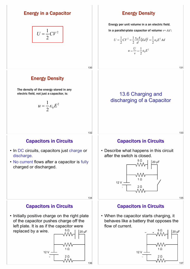
Capacitors in Circuits
In DC circuits, capacitors just charge or discharge. No current flows after a capacitor is fully charged or discharged.
135
Capacitors in Circuits
Describe what happens in this circuit after the switch is closed.
20
12 V
5
1
136
Capacitors in Circuits
Initially positive charge on the right plate of the capacitor pushes charge off the left plate. It is as if the capacitor were replaced by a wire. 20
12 V
5
1
137
Capacitors in Circuits
When the capacitor starts charging, it behaves like a battery that opposes the flow of current. + 20
12 V
5
1

138
20
12 V
5
1
Capacitors in Circuits Eventually, the capacitor becomes fully charged. No more current flows. What is the final voltage on the capacitor?
+
139
20
12 V
5
1
Capacitors in Circuits First, ignore the branch with the capacitor. Rtotal=3 . I = 4 A. V across the 1 resistor is IR = 4 V.
+
140
20
12 V
5
1
Capacitors in Circuits V across the 5 resistor is 0. Why? V across the capacitor is 4 V. Q on the capacitor = CV = 80 C
+
141
Capacitors in Circuits
Summary: In steady state, no current flows through the capacitor. Just find the voltage across the capacitor and you can determine the charge.
142
RC Discharging
Charge a capacitor with a battery to a voltage V. Disconnect the capacitor and attach it to a resistor. The initial charge is Q=CV. The charge decays to zero but what is Q(t)?
Q(t)
Q0
I
t
143
RC Discharging Look at the voltage
around the circuit. We
rule:
0IRCQ
I
CQVC
IRVR
I
144
RC Discharging
The minus sign comes from:
1)I > 0
2)Q is the charge on the capacitor
3)The capacitor is discharging so
dtdQI
QI
IRCQ
0,0
0
0dtdQ
I
CQVC
IRVR
145
RC Discharging
)(1
0
0,0
0
tQRCdt
dQdtdQR
CQ
dtdQI
QI
IRCQ
I
CQVC
IRVR

146
RC Discharging
)(1 tQRCdt
dQ
This is a differential equation, but it is a really easy one to solve.
equations.
i
f
dtRCQ
dQdtRCQ
dQ ln11
147
RC Discharging
/0
0
0
)(
)(
,1)(ln
1
1
0
t
ttQ
Q
eQtQ
RCtRCQ
tQ
dtRCQ
dQ
dtRCQ
dQ
148
RC Time Constant
= RC. has units of seconds. When is big, capacitors charge and discharge slowly. If R is large, not much current flows, so is big.
If C is large, there is a lot of charge that has to flow, so is big.
149
RC Discharging
=1 s =2 s
=3 s
e1
Discharging capacitors with three different time constants. The time constant is the time it takes the charge to drop to 1/e of its original value.
150
RC Charging
A capacitor is initially uncharged.
Use a battery with voltage V0 to charge the capacitor. The voltage increases to V0.
The charge increases to Q=CV0.
V0 C
R
151
RC Charging
We again use
00 CQIRV
I
CQVC
IRVR
0V
152
RC Charging
We again use
0
0
0
0
0
CQ
dtdQRV
dtdQI
CQIRV
I
CQVC
IRVR
0V
153
RC Charging
This differential equation has the solution:
00 CQ
dtdQRV
RC
CVQeQtQ
f
tf
0
/1)(
Try plugging the solution into the differential equation and see if it works!

154
RC Charging
=1 s
=2 s
=3 s
e11
Charging capacitors with three different time constants. The time constant is the time it takes the charge to rise to 1-1/e of its final value.
155
Charging and Discharging
Charging Capacitors What happens to current as time passes?
Current falls away as it becomes less attractive for electrons to move to the plate from the cell. Note: The area under the current-time graph is equal to the amount of charge stored on the plates.
156
What happens to the charge on the plate?
Charge builds up - quickly at first (a lot of electrons arriving each second) and then more slowly. The potential difference is proportional to charge, so the p.d.-time graph is exactly the same shape as the charge-time graph.
157
Charging Capacitors When the capacitor is fully charged, the pd across the plates will equal the emf of the cell charging it.
Look at the diagram.
The cell is trying to push electrons clockwise (with its
capacitor is trying to push electrons anticlockwise (with its push of 2V). Neither wins so no charge flows.
158
Discharging Capacitors Initially there is a large current due to the large potential difference across the plates. The current drops as pd drops.
Notice that the electrons are now moving the opposite way round the circuit so the graph shows the current as negative to show this.
159
Discharging Capacitors
Charge drops quickly at first (due to the large current - which is of course, a large flow of charge). As the charge and therefore the pd across the plates drops, so the charge drops more slowly.
160
Discharging Capacitors
As the potential difference across the plates is directly proportional to the charge on the plates, the p.d.-time graph is the same shape as the charge-time graph as before.
161
Charge/Discharge Cycle

162
R-C circuits So far we have assumed
that all emfs and resistances are constant, time-independent quantities. This assumption fails when we consider a circuit with a capacitor. Lets assume an ideal
source with emf connected to a resistor of resistance R and capacitor with capacitance C.
163
R-C circuits
When the switch is open i is zero, as is the charge on the capacitor q. When the switch is
initially closed the current is maximized, and q is zero. As the capacitor charges i decreases as q increased until q is maximized and i is zero.
164
Decay
165
Decay
166
Charging a Capacitor The capacitor in the figure
is initially uncharged. That means that vbc is zero at time t = 0. According to the loop rule
the voltage across the resistor, vab, is equal to the emf of the source E. The initial current through
the resistor: Io = vab/R = E/R
167
Charging a Capacitor As the capacitor charges,
its voltage vbc increases and the potential difference across the resistor, vab, decreases. The sum of these two
voltages must always be equal to E.
168
Charging a Capacitor When the capacitor is fully charged, vbc = E. Why does the current decrease as the
capacitor charges? Let q represent the charge on the capacitor
and i the current in the circuit as some time t after the switch has been closed. The current will flow counter clockwise. The instantaneous voltages for the resistor and capacitor are:
iRvab Cqvbc
169
Charging a Capacitor
The potential drops by iR from a to b and
by q/C from b to c. Solving the above equation for i we get:
RCq
REi
0CqiRE

170
Charging a Capacitor When the switch is closed at t = 0 the
capacitor is not yet charged, and the initial current is, as we have stated before, E/R. Without the capacitor, this would be the constant value of the current. As q increases the voltage drop across the
capacitor increases. The drop equals E when the charge reaches its final value Qf. The current eventually reaches zero. When this happens Qf = EC.
171
Charging a Capacitor The current and the
capacitor charge are given as functions of time to the right. Current jumps from 0 to Io
= E/R at t = 0, then gradually approaches zero. The charge starts at zero and gradually approaches Qf.
172
Charging a Capacitor We can derive general
expressions for the charge and current as functions of time. Due to our choice of the direction of current, i equals the rate at which positive charge arrives at the left-hand plate of the capacitor, so i = dq/dt. Putting this into equation,
CEqRCRC
qRE
dtdq 1
173
Charging a Capacitor The previous equation rearranged: And then integrate both sides. Lets
change the integration variables to and so we can use q and t as the upper
limits:
RCdt
CEqdq
tq
RCtd
CEqqd
00
174
Charging a Capacitor When we carry out the integration we get: Exponentiating both sides, taking the inverse
logarithm, and solving for q: The instantaneous current i is just the time
derivative:
RCt
CECEqln
)1()1( RCt
fRCt
eQeCEq
RCt
oRCt
eIeRE
dtdqi
175
Time Constant After a time equal to RC,
the current in the R-C circuit has decreased to 1/e of its initial value and the charge has reached (1 1/e) of its final value. The product RC is called the time constant or relaxation time of the circuit, = RC. It is a measure of
how quickly the capacitor charges or discharges.
176
Time Constant
When tau is small, the capacitor charges quickly. When it is large the capacitor takes a longer time to charge. Hence, tau is the factor RC.
177
Discharging a Capacitor Suppose that after the capacitor in figure 26.20 has
acquired a charge Qf we remove the battery and connect points a and c to an open switch. When we close the switch, t = 0 and q = Qo, the
capacitor discharges through the resistor and the charge again returns to zero. Let i and q represent the time varying current and
charge at some instant after the switch is closed. We choose our current direction to be the same as we did before so we can use equation 26.10 for
E = 0. This gives:
RCq
dtdqi

178
Discharging a Capacitor The initial current, when t =0, Io = -Qo/RC. To find q as a function of time we take the same steps as
charging:
RCq
dtdqi
tqtd
RCqqd
00
1
RCt
o
ln
RCt
oeQq
RCt
o
RCto
eI
eRCQdtdqi
RCq
dtdqi
179
180
181
Summary
By Carsten Denker
182
Capacitance
Capacitance [F = C/V]
A battery maintains a potential difference between its terminals. It sets up an electric field which drives electrons through the wire towards the positive terminal.
E
q CV
183
Calculating the Capacitance Parallel-plate capacitor
Cylindrical capacitor
Spherical capacitor
Isolated sphere
0 ACd
02ln /
LCb a
04 abCb a
04C R
184
Capacitors in Parallel & in Series
capacitor in parallel capacitors
in series
When a potential difference is applied across several capacitors connected in parallel, that potential difference is applied across each capacitor. The total charge stored on the capacitors is the sum of the charges stored on all the capacitors. When a potential difference is applied across several capacitors connected in series, the capacitors have identical charges . The sum of the potential
differences across all the capacitors is equal to the applied potential difference .
eq1
n
jj
C C
1eq
1 1n
j jC C
185
Energy Stored in an Electric Field
Potential energy
Potential energy
Energy density
The potential energy of a charged capacitor may be viewed as being stored in the electric field between its plates.
Material
Dielectric Constant
Dielectric Strength (kV/mm)
Air 1.00054 3 Polystyrene 2.6 24 Paper 3.5 16 Transformer Oil 4.5 Pyrex 4.7 14 Ruby Mica 5.4 Porcelain 6.5 Silicon 12 Germanium 16 Ethanol 25 Water (20º C) 80.4 Water (50º C) 78.5 Titania Ceramic 130 Strontium Titanate 310 8
2
2qUC
212
U CV
20
12
u E

186
Dielectric
In a region completely filled by a dielectric material of dielectric constant , all electrostatic equations containing
the permittivity constant are to be modified by replacing with .
Polar and non-polar dielectrics
dielectric
0 E dA q