electrochemical characteristics of polyaniline electrosynthesized in the presence of neutral red
TRANSCRIPT
A
(trrhc©
K
1
mapmo[Tifiwe[m
pmi
0d
Materials Chemistry and Physics 102 (2007) 24–30
Electrochemical characteristics of polyaniline electrosynthesizedin the presence of neutral red
Chuanxiang Chen ∗, Yuhua GaoSchool of Materials Science and Engineering, Jiangsu University of Science and Technoloy, Zhenjiang 212003, PR China
Received 23 March 2006; received in revised form 6 September 2006; accepted 30 October 2006
bstract
Electropolymerization of aniline in the presence of neutral red was carried out by using repeated potential cycling between −0.20 and 1.00 Vversus Ag/AgCl with saturated KCl solution) on a platinum foil from 0.3 mol dm−3 H2SO4 solution at room temperature. The experiments ofhe rotating ring-disk electrode show that an intermediate is generated during electrolysis of aniline and the mixture of aniline and neutral red,espectively. Neutral red can increase the polymerization rate of aniline. The coelectropolymerization of aniline and neutral red is verified from the
esults of UV–visible spectra, FTIR spectra and XPS spectra of the polymers. The conductivity of the copolymer is one to two orders of magnitudeigher than that of polyaniline synthesized under the same conditions but in the absence of neutral red. The electrochemical properties of theopolymer are mainly attributed to polyaniline. 2006 Elsevier B.V. All rights reserved.techn
cOoaeutvriicempocK
eywords: Polyaniline; Poly(neutral red); Copolymerization; Electrochemical
. Introduction
The interesting discovery on the interconversion betweenetallic and insulating forms of polyacetylene [1] has played
n important role in synthesis and applications of conductingolymers. The different applications require conducting poly-ers with different properties, thus, the synthesis of new types
f conducting polymers is very important for materials sciences2]. Some of the indicators and dyes can be oxidized or reduced.his means that some of them may be polymerized electrochem-
cally. Cyclic voltammetry has become a very popular techniqueor initial electrochemical studies of various systems. Among thendicators and dyes under investigation, we found neutral redas to be polymerized electrochemically on glassy carbon disk
lectrode from strong acids by using the potential sweep method3]. This is much different from that in neutral or basic aqueousedia neutral red can be polymerized electrochemically [4–8].Among conducting polymers, the copolymerization of
yrrole and thiophene (or bithiophene) [9–14] and the copoly-erization of pyrrole and furan [15] have been extensively
nvestigated. Compared with pyrrole, the reports about the
∗ Corresponding author. Tel.: +86 5114401181; fax: +86 5114407381.E-mail address: [email protected] (C. Chen).
otoc
tT
254-0584/$ – see front matter © 2006 Elsevier B.V. All rights reserved.oi:10.1016/j.matchemphys.2006.10.005
iques; Electrochemical properties
opolymerization of aniline and other monomers are scanty.ne of the reasons is that the electrochemical polymerizationf aniline in acid solutions is quite fast, but it is very slowt pH > 1. Ruckenstein and Yang reported the preparation oflectrically conductive polyaniline–polystyrene composites bysing an emulsion pathway [16]. Sari and Talu [17] reportedhe copolymerization of aniline and pyrrole was carried outia two steps, i.e., polyaniline was synthesized first and pyr-ole was polymerized afterwards. Fusalba and Belanger [18]nvestigated the coelectropolymerization of pyrrole and anilinen organic acid medium. They found that the IR spectrum of theopolymer was not a simple surperposition of the spectrum ofach individual polymer. This means that the resulting poly-er is a copolymer instead of a mixture of polypyrrole and
olyaniline. Mu reported the electrochemical copolymerizationf aniline and o-aminophenol [19], rechargeable batteries on theopolymer and the protonation of the copolymer [20]. Recently,an et al. [21] investigated the copolymerization of aniline and-chloroaniline by using cyclicvoltammetry. The copolymeriza-ion of them is different from the monopolymerization of aniliner o-chloroaniline in terms of growth rate, redoxpotentials, and
harge transport mechanisms.Mu and co-workers [22] reported the coelectropolymeriza-ion of azure B and aniline in sodium chlorate solution (pH 5.57).hey reported that the conductivity of the copolymer synthesized
istry
isa
rtstiga(Tnotcs(co
aaea
2
As
verrp3wAiypKlfuaar
iur04tspwa
osp
3
3
stitrcb
us0pftcdcnctatworking electrode.
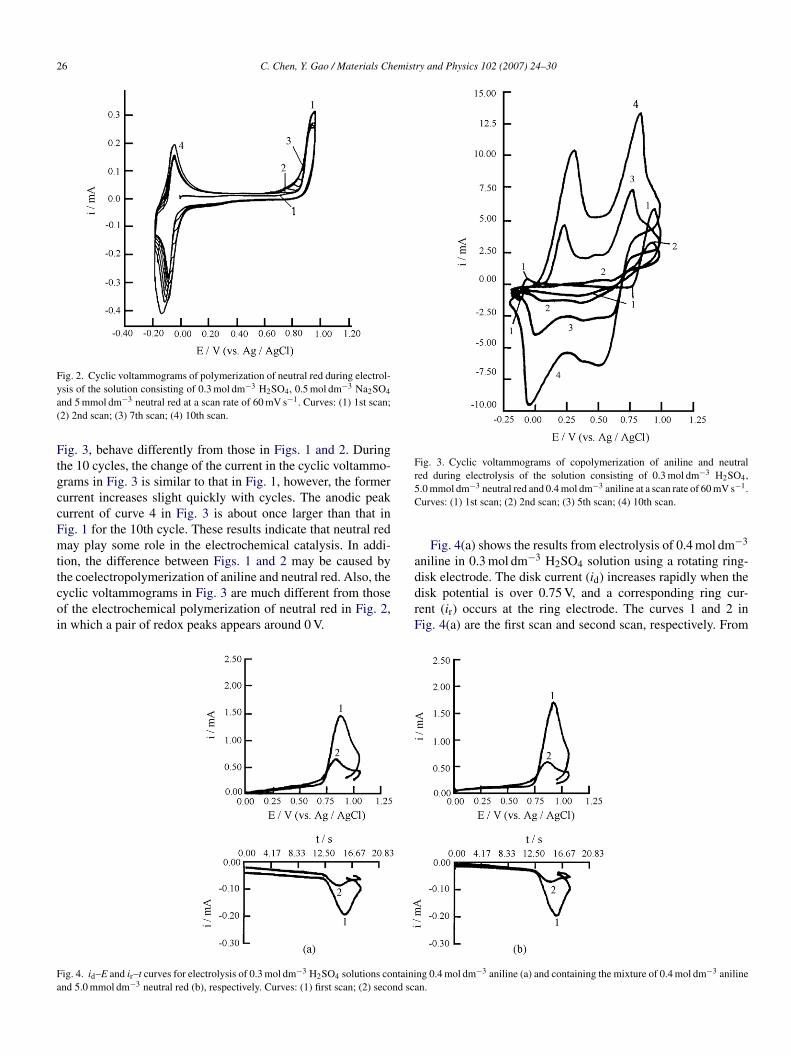
Fig. 3 shows that the cyclic voltammograms were in the solu-tion containing 0.4 mol dm−3 aniline, 5.0 mmol dm−3 neutralred and 0.3 mol dm−3 H2SO4. The cyclic voltammograms in
C. Chen, Y. Gao / Materials Chem
s four orders of magnitude higher than that of polyanilineynthesized under the same conditions, but in the absence ofzure B.
In the strong acid solutions, neutral red can be oxidized andeduced reversibly around 0 V and can be polymerized at poten-ials higher than 0.80 V (versus Ag/AgCl with saturated KClolution) on a glassy carbon disk electrode [3]. The polymeriza-ion potential of neutral red is close to that of aniline. Therefore,t may be possible to copolymerize neutral red with aniline. Toain a better understanding of the polymerization mechanism ofniline and neutral red, we try to use rotating ring-disk electrodeRRDE) to study the electrochemical polymerization of them.his is due to the fact that RRDE experiment can provide a rich-ess of information about the formation, detection and decayf an intermediate [23]. Also this technique can easily iden-ify whether an intermediate generated at the disk electrode isharged or not by varying the ring electrode potentials [24]. Con-idering the following fact that the X-ray photoelectron spectraXPS) have been successfully employed to study that the anionsan be doped into polymer film and dedoped from it duringxidation and reduction processes [22,25].
In this paper, we studied the coelectropolymerization ofniline and neutral red in the strong acid solutions, and char-cterized the copolymer by the measurements of conductivity,lectrochemical properties, UV–visible spectrum, IR spectrumnd XPS spectrum.
. Experimental
Neutral red and other chemicals used in this work were of reagent grade.niline was distilled before use. Doubly distilled water was used to prepare
olutions.All the electrochemical experiments were carried out at 20 ± 1 ◦C. The pH
alue of the solutions was measured by using a Model PXD-12 pH meter. Thelectrolysis cell consisted of two platinum foils and an Ag/AgCl (with satu-ated KCl solution) reference electrode (all potentials are given against thiseference). The area of the working electrode was 3 mm × 3 mm. A HPD-1Aotentiostat–galvanostat was used for the cyclic voltammetry. A YEW Model086 X-Y recorder was used to record the cyclic voltammograms. The scan rateas 60 mV s−1. The sweeping potential range was between −0.20 and 1.00 V.Model HR-103A (Japan) rotating ring-disk electrode was also used for the
nvestigation on the copolymerization of aniline and neutral red. The electrol-sis cell consisted of a platinum disk electrode, a platinum ring electrode, alatinum counter electrode and a reference electrode of Ag/AgCl with saturatedCl solution. The diameter of the platinum disk electrode is 7.89 mm. The col-
ection efficiency of the RRDE is 0.4187. The disk current and ring current asunction of potential and time, respectively, were recorded simultaneously bysing a Model 3086 bipen recorder. The ring electrode was controlled at 0.10 V,nd the disk potential was scanned from 0 V in a positive direction and stoppedt 1.10 V. The rotation rate of the RRDE was controlled at 1000 rpm. The scanate was also 60 mV s−1 in the RRDE experiment.
The measurements of the UV–visible spectra of polymers formed on plat-num deposited on quartz glass were carried out in the range 200–800 nm bysing an UV-2501 PC spectrophotometer. The UV–visible spectrum of neutraled was determined in neutral red solution consisting of small neutral red and.3 mol dm−3 H2SO4. FTIR spectra of polymers were measured in the range00–4000 cm−1 on pressed pellets with KBr by using a Nicolet 740 FTIR spec-
rometer. XPS spectra were measured on a VG Escalab 220i-XL photoelectronpectrometer with Al K� exciting radiation used at 15 kV and 20 mA; the baseressure was approximately 10−9 Torr. Survey scans in the range 0–1200 eVere recorded for XPS spectra of the copolymer polymerized on platinum foilt a pass energy of 100 eV with a step size of 1 eV. Core-level spectra were
Foa1
and Physics 102 (2007) 24–30 25
btained for C 1s, N 1s, S 2p and O 1s with a pass energy of 40 eV and a stepize of 50 meV. The conductivity of each polymer was measured on a pressedellet by using a four-probe technique.
. Results and discussion
.1. Effect of neutral red on the polymerization of aniline
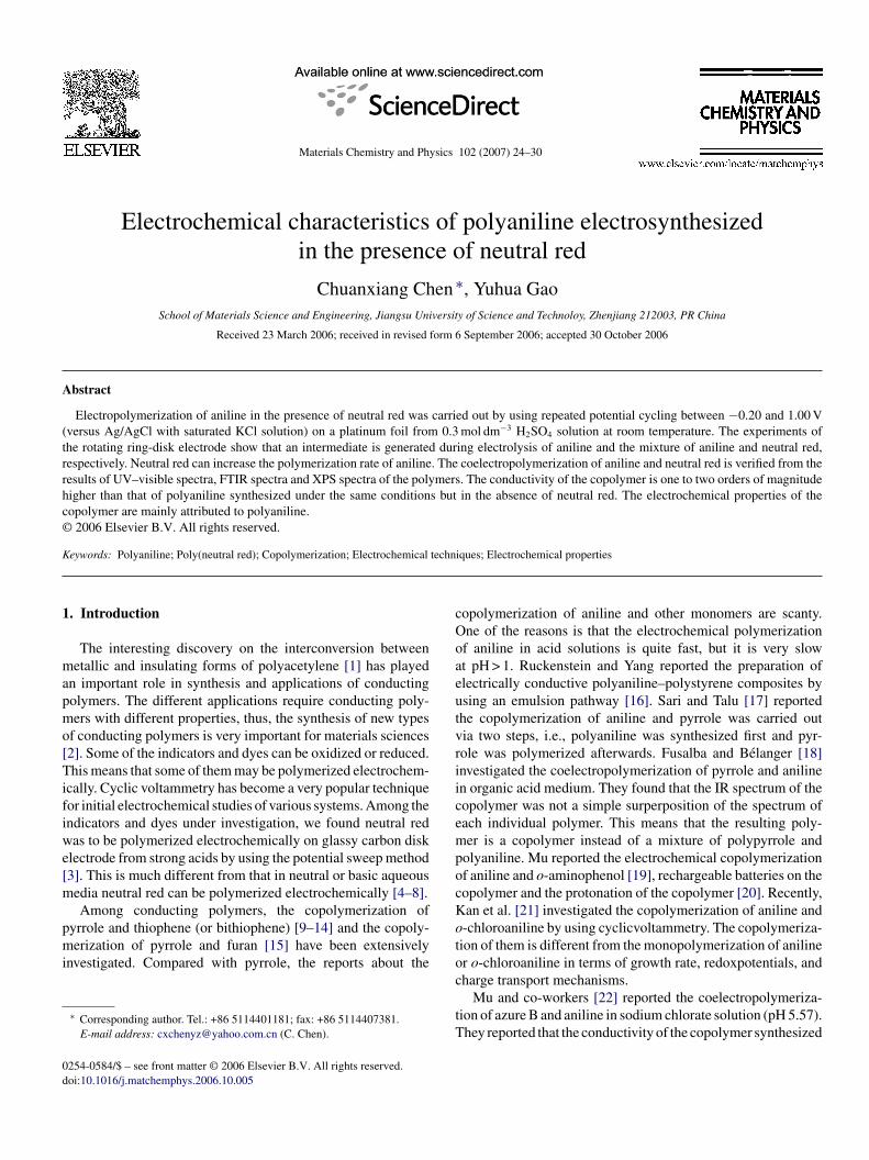
Fig. 1 displays that the cyclic voltammetry was carried out totudy the electropolymerization of aniline in the solution con-aining 0.4 mol dm−3 aniline and 0.3 mol dm−3 H2SO4. Theres an anodic peak at 0.80 V and a cathodic peak at 0.20 V inhe 1st cycle (curve 1 in Fig. 1), and then the anodic peak cur-ent decreases markedly in the subsequent cycles until the 10thycle (curve 4 in Fig. 1). This means that polyaniline film cane growing with time in 0.3 mol dm−3 H2SO4 solution.
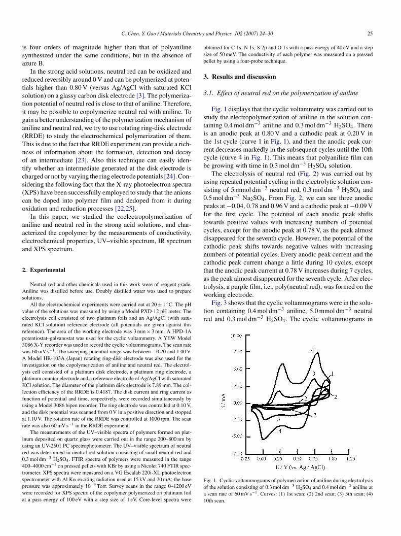
The electrolysis of neutral red (Fig. 2) was carried out bysing repeated potential cycling in the electrolytic solution con-isting of 5 mmol dm−3 neutral red, 0.3 mol dm−3 H2SO4 and.5 mol dm−3 Na2SO4. From Fig. 2, we can see three anodiceaks at −0.04, 0.78 and 0.96 V and a cathodic peak at −0.09 Vor the first cycle. The potential of each anodic peak shiftsowards positive values with increasing numbers of potentialycles, except for the anodic peak at 0.78 V, as the peak almostisappeared for the seventh cycle. However, the potential of theathodic peak shifts towards negative values with increasingumbers of potential cycles. Every anodic peak current and theathodic peak current change a little during 10 cycles, excepthat the anodic peak current at 0.78 V increases during 7 cycles,s the peak almost disappeared for the seventh cycle. After elec-rolysis, a purple film, i.e., poly(neutral red), was formed on the
ig. 1. Cyclic voltammograms of polymerization of aniline during electrolysisf the solution consisting of 0.3 mol dm−3 H2SO4 and 0.4 mol dm−3 aniline atscan rate of 60 mV s−1. Curves: (1) 1st scan; (2) 2nd scan; (3) 5th scan; (4)0th scan.
26 C. Chen, Y. Gao / Materials Chemistry and Physics 102 (2007) 24–30
Fig. 2. Cyclic voltammograms of polymerization of neutral red during electrol-ya(
FtgccFmttcoi
Fig. 3. Cyclic voltammograms of copolymerization of aniline and neutralr −3
5C
a
Fa
sis of the solution consisting of 0.3 mol dm−3 H2SO4, 0.5 mol dm−3 Na2SO4
nd 5 mmol dm−3 neutral red at a scan rate of 60 mV s−1. Curves: (1) 1st scan;2) 2nd scan; (3) 7th scan; (4) 10th scan.
ig. 3, behave differently from those in Figs. 1 and 2. Duringhe 10 cycles, the change of the current in the cyclic voltammo-rams in Fig. 3 is similar to that in Fig. 1, however, the formerurrent increases slight quickly with cycles. The anodic peakurrent of curve 4 in Fig. 3 is about once larger than that inig. 1 for the 10th cycle. These results indicate that neutral reday play some role in the electrochemical catalysis. In addi-
ion, the difference between Figs. 1 and 2 may be caused by
he coelectropolymerization of aniline and neutral red. Also, theyclic voltammograms in Fig. 3 are much different from thosef the electrochemical polymerization of neutral red in Fig. 2,n which a pair of redox peaks appears around 0 V.ddrF
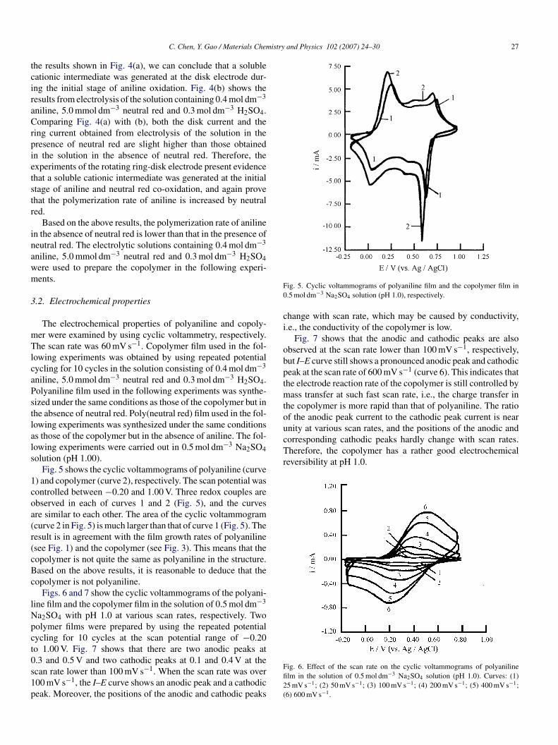
ig. 4. id–E and ir–t curves for electrolysis of 0.3 mol dm−3 H2SO4 solutions containind 5.0 mmol dm−3 neutral red (b), respectively. Curves: (1) first scan; (2) second sca
ed during electrolysis of the solution consisting of 0.3 mol dm H2SO4,.0 mmol dm−3 neutral red and 0.4 mol dm−3 aniline at a scan rate of 60 mV s−1.urves: (1) 1st scan; (2) 2nd scan; (3) 5th scan; (4) 10th scan.
Fig. 4(a) shows the results from electrolysis of 0.4 mol dm−3
niline in 0.3 mol dm−3 H2SO4 solution using a rotating ring-
isk electrode. The disk current (id) increases rapidly when theisk potential is over 0.75 V, and a corresponding ring cur-ent (ir) occurs at the ring electrode. The curves 1 and 2 inig. 4(a) are the first scan and second scan, respectively. Fromng 0.4 mol dm−3 aniline (a) and containing the mixture of 0.4 mol dm−3 anilinen.
istry and Physics 102 (2007) 24–30 27
tciraCrpietstr
inawm
3
mTlcaPstlals
1coa(r(cBc
lNpct0s1p
F0
ci
obptmtounity at various scan rates, and the positions of the anodic andcorresponding cathodic peaks hardly change with scan rates.Therefore, the copolymer has a rather good electrochemicalreversibility at pH 1.0.
C. Chen, Y. Gao / Materials Chem
he results shown in Fig. 4(a), we can conclude that a solubleationic intermediate was generated at the disk electrode dur-ng the initial stage of aniline oxidation. Fig. 4(b) shows theesults from electrolysis of the solution containing 0.4 mol dm−3
niline, 5.0 mmol dm−3 neutral red and 0.3 mol dm−3 H2SO4.omparing Fig. 4(a) with (b), both the disk current and the
ing current obtained from electrolysis of the solution in theresence of neutral red are slight higher than those obtainedn the solution in the absence of neutral red. Therefore, thexperiments of the rotating ring-disk electrode present evidencehat a soluble cationic intermediate was generated at the initialtage of aniline and neutral red co-oxidation, and again provehat the polymerization rate of aniline is increased by neutraled.
Based on the above results, the polymerization rate of anilinen the absence of neutral red is lower than that in the presence ofeutral red. The electrolytic solutions containing 0.4 mol dm−3
niline, 5.0 mmol dm−3 neutral red and 0.3 mol dm−3 H2SO4ere used to prepare the copolymer in the following experi-ents.
.2. Electrochemical properties
The electrochemical properties of polyaniline and copoly-er were examined by using cyclic voltammetry, respectively.he scan rate was 60 mV s−1. Copolymer film used in the fol-
owing experiments was obtained by using repeated potentialycling for 10 cycles in the solution consisting of 0.4 mol dm−3
niline, 5.0 mmol dm−3 neutral red and 0.3 mol dm−3 H2SO4.olyaniline film used in the following experiments was synthe-ized under the same conditions as those of the copolymer but inhe absence of neutral red. Poly(neutral red) film used in the fol-owing experiments was synthesized under the same conditionss those of the copolymer but in the absence of aniline. The fol-owing experiments were carried out in 0.5 mol dm−3 Na2SO4olution (pH 1.00).
Fig. 5 shows the cyclic voltammograms of polyaniline (curve) and copolymer (curve 2), respectively. The scan potential wasontrolled between −0.20 and 1.00 V. Three redox couples arebserved in each of curves 1 and 2 (Fig. 5), and the curvesre similar to each other. The area of the cyclic voltammogramcurve 2 in Fig. 5) is much larger than that of curve 1 (Fig. 5). Theesult is in agreement with the film growth rates of polyanilinesee Fig. 1) and the copolymer (see Fig. 3). This means that theopolymer is not quite the same as polyaniline in the structure.ased on the above results, it is reasonable to deduce that theopolymer is not polyaniline.
Figs. 6 and 7 show the cyclic voltammograms of the polyani-ine film and the copolymer film in the solution of 0.5 mol dm−3
a2SO4 with pH 1.0 at various scan rates, respectively. Twoolymer films were prepared by using the repeated potentialycling for 10 cycles at the scan potential range of −0.20o 1.00 V. Fig. 7 shows that there are two anodic peaks at
.3 and 0.5 V and two cathodic peaks at 0.1 and 0.4 V at thecan rate lower than 100 mV s−1. When the scan rate was over00 mV s−1, the I–E curve shows an anodic peak and a cathodiceak. Moreover, the positions of the anodic and cathodic peaksFfi2(
ig. 5. Cyclic voltammograms of polyaniline film and the copolymer film in.5 mol dm−3 Na2SO4 solution (pH 1.0), respectively.
hange with scan rate, which may be caused by conductivity,.e., the conductivity of the copolymer is low.
Fig. 7 shows that the anodic and cathodic peaks are alsobserved at the scan rate lower than 100 mV s−1, respectively,ut I–E curve still shows a pronounced anodic peak and cathodiceak at the scan rate of 600 mV s−1 (curve 6). This indicates thathe electrode reaction rate of the copolymer is still controlled by
ass transfer at such fast scan rate, i.e., the charge transfer inhe copolymer is more rapid than that of polyaniline. The ratiof the anodic peak current to the cathodic peak current is near
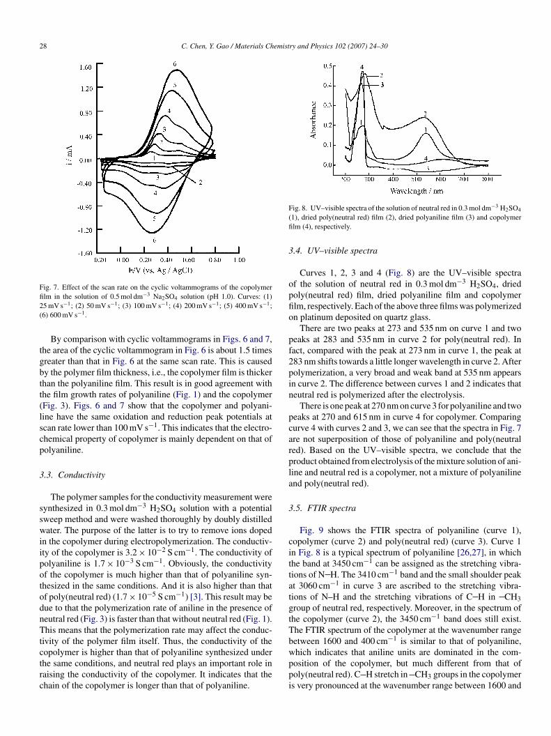
ig. 6. Effect of the scan rate on the cyclic voltammograms of polyanilinelm in the solution of 0.5 mol dm−3 Na2SO4 solution (pH 1.0). Curves: (1)5 mV s−1; (2) 50 mV s−1; (3) 100 mV s−1; (4) 200 mV s−1; (5) 400 mV s−1;6) 600 mV s−1.
28 C. Chen, Y. Gao / Materials Chemistry and Physics 102 (2007) 24–30
Fig. 7. Effect of the scan rate on the cyclic voltammograms of the copolymerfi2(
tgbtt(lscp
3
sswiipotodnTtctrc
F(fi
3
opfio
pf2pin
pcarpla
3
cittatgtTb
lm in the solution of 0.5 mol dm−3 Na2SO4 solution (pH 1.0). Curves: (1)5 mV s−1; (2) 50 mV s−1; (3) 100 mV s−1; (4) 200 mV s−1; (5) 400 mV s−1;6) 600 mV s−1.
By comparison with cyclic voltammograms in Figs. 6 and 7,he area of the cyclic voltammogram in Fig. 6 is about 1.5 timesreater than that in Fig. 6 at the same scan rate. This is causedy the polymer film thickness, i.e., the copolymer film is thickerhan the polyaniline film. This result is in good agreement withhe film growth rates of polyaniline (Fig. 1) and the copolymerFig. 3). Figs. 6 and 7 show that the copolymer and polyani-ine have the same oxidation and reduction peak potentials atcan rate lower than 100 mV s−1. This indicates that the electro-hemical property of copolymer is mainly dependent on that ofolyaniline.
.3. Conductivity
The polymer samples for the conductivity measurement wereynthesized in 0.3 mol dm−3 H2SO4 solution with a potentialweep method and were washed thoroughly by doubly distilledater. The purpose of the latter is to try to remove ions doped
n the copolymer during electropolymerization. The conductiv-ty of the copolymer is 3.2 × 10⁻² S cm−1. The conductivity ofolyaniline is 1.7 × 10⁻³ S cm−1. Obviously, the conductivityf the copolymer is much higher than that of polyaniline syn-hesized in the same conditions. And it is also higher than thatf poly(neutral red) (1.7 × 10⁻⁵ S cm−1) [3]. This result may beue to that the polymerization rate of aniline in the presence ofeutral red (Fig. 3) is faster than that without neutral red (Fig. 1).his means that the polymerization rate may affect the conduc-
ivity of the polymer film itself. Thus, the conductivity of the
opolymer is higher than that of polyaniline synthesized underhe same conditions, and neutral red plays an important role inaising the conductivity of the copolymer. It indicates that thehain of the copolymer is longer than that of polyaniline.wppi
ig. 8. UV–visible spectra of the solution of neutral red in 0.3 mol dm−3 H2SO4
1), dried poly(neutral red) film (2), dried polyaniline film (3) and copolymerlm (4), respectively.
.4. UV–visible spectra
Curves 1, 2, 3 and 4 (Fig. 8) are the UV–visible spectraf the solution of neutral red in 0.3 mol dm−3 H2SO4, driedoly(neutral red) film, dried polyaniline film and copolymerlm, respectively. Each of the above three films was polymerizedn platinum deposited on quartz glass.
There are two peaks at 273 and 535 nm on curve 1 and twoeaks at 283 and 535 nm in curve 2 for poly(neutral red). Inact, compared with the peak at 273 nm in curve 1, the peak at83 nm shifts towards a little longer wavelength in curve 2. Afterolymerization, a very broad and weak band at 535 nm appearsn curve 2. The difference between curves 1 and 2 indicates thateutral red is polymerized after the electrolysis.
There is one peak at 270 nm on curve 3 for polyaniline and twoeaks at 270 and 615 nm in curve 4 for copolymer. Comparingurve 4 with curves 2 and 3, we can see that the spectra in Fig. 7re not superposition of those of polyaniline and poly(neutraled). Based on the UV–visible spectra, we conclude that theroduct obtained from electrolysis of the mixture solution of ani-ine and neutral red is a copolymer, not a mixture of polyanilinend poly(neutral red).
.5. FTIR spectra
Fig. 9 shows the FTIR spectra of polyaniline (curve 1),opolymer (curve 2) and poly(neutral red) (curve 3). Curve 1n Fig. 8 is a typical spectrum of polyaniline [26,27], in whichhe band at 3450 cm−1 can be assigned as the stretching vibra-ions of N H. The 3410 cm−1 band and the small shoulder peakt 3060 cm−1 in curve 3 are ascribed to the stretching vibra-ions of N–H and the stretching vibrations of C H in CH3roup of neutral red, respectively. Moreover, in the spectrum ofhe copolymer (curve 2), the 3450 cm−1 band does still exist.he FTIR spectrum of the copolymer at the wavenumber rangeetween 1600 and 400 cm−1 is similar to that of polyaniline,
hich indicates that aniline units are dominated in the com-osition of the copolymer, but much different from that ofoly(neutral red). C H stretch in CH3 groups in the copolymers very pronounced at the wavenumber range between 1600 and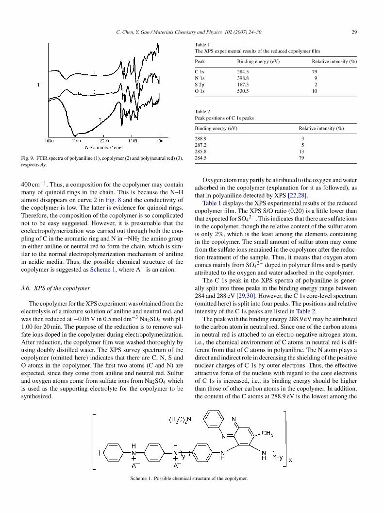
C. Chen, Y. Gao / Materials Chemistry and Physics 102 (2007) 24–30 29
Fr
4matTncpiiic
3
ew1fAucOeais
Table 1The XPS experimental results of the reduced copolymer film
Peak Binding energy (eV) Relative intensity (%)
C 1s 284.5 79N 1s 398.8 9S 2p 167.3 2O 1s 530.5 10
Table 2Peak positions of C 1s peaks
Binding energy (eV) Relative intensity (%)
288.9 3287.2 522
at
ctiiiftca
a2(i
tiifdn
ig. 9. FTIR spectra of polyaniline (1), copolymer (2) and poly(neutral red) (3),espectively.
00 cm−1. Thus, a composition for the copolymer may containany of quinoid rings in the chain. This is because the N H
lmost disappears on curve 2 in Fig. 8 and the conductivity ofhe copolymer is low. The latter is evidence for quinoid rings.herefore, the composition of the copolymer is so complicatedot to be easy suggested. However, it is presumable that theoelectropolymerization was carried out through both the cou-ling of C in the aromatic ring and N in NH2 the amino groupn either aniline or neutral red to form the chain, which is sim-lar to the normal electropolymerization mechanism of anilinen acidic media. Thus, the possible chemical structure of theopolymer is suggested as Scheme 1, where A− is an anion.
.6. XPS of the copolymer
The copolymer for the XPS experiment was obtained from thelectrolysis of a mixture solution of aniline and neutral red, andas then reduced at −0.05 V in 0.5 mol dm−3 Na2SO4 with pH.00 for 20 min. The purpose of the reduction is to remove sul-ate ions doped in the copolymer during electropolymerization.fter reduction, the copolymer film was washed thoroughly bysing doubly distilled water. The XPS survey spectrum of theopolymer (omitted here) indicates that there are C, N, S and
atoms in the copolymer. The first two atoms (C and N) are
xpected, since they come from aniline and neutral red. Sulfurnd oxygen atoms come from sulfate ions from Na2SO4 whichs used as the supporting electrolyte for the copolymer to beynthesized.aott
Scheme 1. Possible chemical st
85.8 1384.5 79
Oxygen atom may partly be attributed to the oxygen and waterdsorbed in the copolymer (explanation for it as followed), ashat in polyaniline detected by XPS [22,28].
Table 1 displays the XPS experimental results of the reducedopolymer film. The XPS S/O ratio (0.20) is a little lower thanhat expected for SO4
2−. This indicates that there are sulfate ionsn the copolymer, though the relative content of the sulfur atoms only 2%, which is the least among the elements containingn the copolymer. The small amount of sulfur atom may comerom the sulfate ions remained in the copolymer after the reduc-ion treatment of the sample. Thus, it means that oxygen atomomes mainly from SO4
2− doped in polymer films and is partlyttributed to the oxygen and water adsorbed in the copolymer.
The C 1s peak in the XPS spectra of polyaniline is gener-lly split into three peaks in the binding energy range between84 and 288 eV [29,30]. However, the C 1s core-level spectrumomitted here) is split into four peaks. The positions and relativentensity of the C 1s peaks are listed in Table 2.
The peak with the binding energy 288.9 eV may be attributedo the carbon atom in neutral red. Since one of the carbon atomsn neutral red is attached to an electro-negative nitrogen atom,.e., the chemical environment of C atoms in neutral red is dif-erent from that of C atoms in polyaniline. The N atom plays airect and indirect role in decreasing the shielding of the positiveuclear charges of C 1s by outer electrons. Thus, the effective
ttractive force of the nucleus with regard to the core electronsf C 1s is increased, i.e., its binding energy should be higherhan those of other carbon atoms in the copolymer. In addition,he content of the C atoms at 288.9 eV is the lowest among theructure of the copolymer.
30 C. Chen, Y. Gao / Materials Chemist
Table 3Peak positions of S 2p peaks
Binding energy (eV) Relative intensity (%)
167.8 96164.3 4
Table 4Peak positions of N 1s peaks
Binding energy (eV) Relative intensity (%)
43
ff
s(mcord
t((7entt0t
4
rrcrsiiaanou
Tce1arm
A
dPs
R
[[
[[
[
[
[[[[[[[
[[[[
00.5 2398.8 77
our kinds of C 1s, which is also an evidence for C 1s originatingrom neutral red.
The S 2p spectrum (omitted here) of the copolymer con-ists of two peaks with bending energies of 167.8 and 164.3 eVTable 3). The first is attributed to the sulfate ions, and is theore intense as it represents 96% of the sulfur. Thus, the S 2p
omponent at lower binding energy can be assigned that somef the sulfur atoms exists in a more negative environment andesult from charge relaxation from some of the sulfuric unitsopant by the reduced copolymer units.
The XPS N 1s core-level spectrum (omitted here) con-ains two peaks with bending energies of 400.5 and 398.8 eVTable 4). The latter is attributed to the imine ( N ) and amine
NH ) nitrogens [18], and is the more intense as it represents7% of the nitrogen. The N 1s component at higher bindingnergy can be assigned to a positively charged nitrogen of theeutral red and aniline units which are charge compensated byhe sulfate ions. The fraction of positively charged nitrogen forhe N 1s envelop corresponds to the doping level and a value of.23 is obtained from the XPS data. This compares well withhe XPS S/N ratio (0.22).
. Conclusion
The experimental results indicate that the polymerizationate of aniline from the strong acid in the presence of neutraled is higher than that in the absence of neutral red. This isaused by the coelectropolymerization of aniline and neutraled. This is evidenced from the measurements of UV–visiblepectra, FTIR spectra and XPS spectra of polymers. The exper-mental results of RRDE also prove that a positively chargedntermediate is generated during electrolysis of neutral red,niline and the mixture of aniline and neutral red, respectively,
nd that the polymerization rate of aniline is increased byeutral red. The conductivity of the copolymer is one to tworders of magnitude higher than that of polyaniline synthesizednder the same conditions but in the absence of neutral red.[[[[
ry and Physics 102 (2007) 24–30
he electrochemical properties of the copolymer are mainlyontributed to polyaniline, but the copolymer has a betterlectrochemical reversibility than that of polyaniline at pH.0. It is clear that the coelectropolymerization mechanism ofniline and neutral red, and the structure of the copolymer areather complicated. Thus, a further study for the polymerizationechanism and the structure of copolymer is required.
cknowledgements
This work was supported by the Social Development Foun-ation of Zhenjiang (No. SH200676). The authors wish to thankrof. Shaolin Mu, Department of Chemistry, Yangzhou Univer-ity, for his laboratory facilities in the work.
eferences
[1] M.M. Maricq, J.S. Waugh, A.G. MacDiarmid, H. Shirakawa, A.J. Heeger,J. Am. Chem. Soc. 100 (1978) 7729.
[2] C.-X. Chen, Y.-H. Gao, Mater. Lett. 58 (2004) 3385.[3] C.-X. Chen, H.-P. Zhu, Bull. Electrochem. 18 (2002) 247.[4] A.A. Karyakin, E.E. Karyakina, H.L. Schmidt, Electroanalysis 11 (1999)
149.[5] S.-M. Chen, K.-C. Lin, J. Electroanal. Chem. 511 (2001) 101.[6] D. Benito, C. Gabrielli, J.J. Garcia-Jareno, M. Keddam, H. Perrot, F.
Vicente, Electrochim. Acta 48 (2003) 4039.[7] M.E. Ghica, C.M.A. Brett, Anal. Lett. 39 (2006) 1527.[8] F.-L. Qu, M.-H. Yang, J.-W. Chen, G.-L. Shen, R.Q. Yu, Anal. Lett. 39
(2006) 1785.[9] O. Inganas, B. Liedberg, C.-R. Wu, H. Wynberg, Synth. Met. 11 (1985)
239.10] S. Kuwabata, S. Ito, H. Yoneyama, J. Electrochem. Soc. 135 (1988) 1691.11] D. Gningue, G. Horowitz, F. Garnier, J. Electrochem. Soc. 135 (1988)
1695.12] H. Laborde, J.M. Leger, C. Lamy, J. Appl. Electrochem. 20 (1990) 524.13] M. Sanchez, D. Pinto, H.T. Mishima, B.A. Mishima, J. Appl. Electrochem.
27 (1997) 831.14] G. Zotti, M. Musiani, S. Zecchin, G. Schiavon, Chem. Mater. 10 (1998)
480.15] X.-B. Wan, W. Zhang, S. Jin, G. Xue, Q.-D. You, B. Che, J. Electroanal.
Chem. 470 (1999) 23.16] E. Ruckenstein, S.-Y. Yang, Synth. Met. 53 (1993) 283.17] B. Sari, M. Talu, Synth. Met. 94 (1998) 221.18] F. Fusalba, D. Belanger, J. Phys. Chem. B 103 (1999) 9044.19] S.-L. Mu, Synth. Met. 143 (2004) 259.20] S.-L. Mu, Synth. Met. 143 (2004) 269.21] J.-Q. Kan, X.-H. Pan, W.-D. Zhou, Bull. Electrochem. 21 (2005) 65.22] D. Shan, S.-L. Mu, B.-W. Mao, Y.-F. Li, Chin. J. Polym. Sci. 19 (2001)
483.23] S.-L. Mu, D.-H. Sun, Synth. Met. 43 (1991) 3085.24] D. Shan, S.-L. Mu, B.-W. Mao, Electroanalysis 13 (2001) 493.25] S.-L. Mu, Bull. Electrochem. 6 (1990) 719.26] W.-S. Huang, B.D. Humphrey, A.G. MacDiarmid, J. Chem. Soc. Faraday
Trans. I 82 (1986) 2385.27] J.-S. Tang, X.-B. Jing, B.-C. Wang, F.-S. Wang, Synth. Met. 24 (1988) 231.28] P. Snauwaert, R. Lazzaroni, J. Riga, J.J. Verbist, Synth. Met. 16 (1986) 245.29] E.-T. Kang, K.-G. Neoh, K.-L. Tan, Surf. Interface Anal. 20 (1993) 833.30] H.-Y. Wang, S.-L. Mu, Sens. Actuators B 56 (1999) 22.