electrocraft wintriss sfi · changes for revision d of the electrocraft wintriss sfi user manual...
TRANSCRIPT

Electrocraft Wintriss SFIServoFeed Interface for:SmartPACSmartPAC 2SmartPAC PRODiPro 1500ProCam 15001109200Rev. D May 2018
Tech Support Hotline 800-586-8324 8-5 EST
www.wintriss.com
®
®
®®
®®
®
Wintriss Controls Group, LLC100 Discovery WayUnit 110Acton MA 01720 USAPhone (800) 586-8324Fax (978) 263-2048
PRINTED IN USA DA46092
®


Changes for Revision D of the
Electrocraft Wintriss SFI User Manual (1109200)
Revision D of the Electrocraft Wintriss SFI User Manual covers all Electrocraft SFI software versions.
The changes for Revision D include:
• Added installation and other information for using with SmartPAC PRO.
• Added wiring diagrams: Figure 7. SmartPAC to Dallas – Emerson Drive Wiring Diagram Figure 9. SmartPAC to Feedlease – Electrocraft SFI with Emerson Drive M702 Wiring Diagram
PROVIDE IMPORTANT INFO DURING TROUBLESHOOTING WITH WINTRISS TECH SUPPORT!
Whenever you need to contact Wintriss Tech. Support for technical assistance, be ready to provide some important information to help solve the problem. Please supply: product name (e.g. SmartPAC standard); installed options (e.g., SFI, etc.); and firmware version number (e.g., Vs. 2.00). You can determine the last two items by going into “Installed Options” in Initialization mode. You can also determine firmware version number from the labeled chip on the firmware board (see Figure 2-1, page 21, for location on original SmartPAC).


Thank you for purchasing a Wintriss Product. We appreciate your business and want to do whatever we can to ensure your satisfaction. Wintriss products are built to stay on the job day after day, and are backed by an ironclad guarantee, international standards approvals, and unbeatable support. Whenever you need assistance or service, we back all our products with excellent spare parts inventories, training programs, and prompt repair service. We would like to share with you a list of service options–probably the largest number of service options offered in the industry. • Technical Assistance We offer a toll-free line for technical assistance. Call our Wintriss Technical Support Hotline at
1-800-586-TECH (8324) should you have any questions about your equipment. Our technical staff is ready to assist you Monday through Friday, 8 a.m. to 5 p.m. EST. In many cases our experienced technical staff can resolve your inquiry right over the phone.
• Return Authorization Please call our “800” number for a return authorization (RMA) number to return a product for
repair. Returned goods must arrive freight prepaid. In order to process your return quickly, we ask that you provide us with the following pertinent information when you call: purchase order number, shipping address, contact name and telephone number, and product type. The assigned RMA number should appear on all packages returned to Wintriss Controls Group to ensure prompt service.
At the time of requesting an RMA, you will be quoted a flat-rate repair price for the product you are returning. We ask that you either fax us a PO for that amount or enclose the PO with the returned item. This will enable us to ship the item back to you as soon as the repair has been completed. If the item cannot be repaired or there are additional charges, you will be contacted for approval.
Please be sure to carefully pack all returned items and ship to our Acton, MA location. • Expedited Repair Program Rush service providing 48 hour turnaround is available for most products upon request. An
Expedite Fee will be applied to our standard repair rate. • Board Exchange Program If your needs are urgent, you can take advantage of out Board Exchange (EX) program. Call our
“800” number between 8 a.m. to 5 p.m. EST and we will send a replacement to you overnight. A fee does apply to this service. Contact Wintriss Technical Support at 800-586-8324 for details.
• Service Center Our Service Center for product service is located at our headquarters in Acton, MA. If your
equipment requires repair, please contact us at 800-586-8324 to obtain a return authorization number.
Nationwide field service is also available. Contact the Wintriss Technical Support group at 800-586-8324.
• Product Training We also offer both product training and maintenance/troubleshooting courses at our Acton, MA
and Chicago-area facilities. On-site training is available from the factory or through your local Wintriss representative.
• Restocking Charge Returned goods are subject to a 20% restocking charge if returned for credit. The minimum charge
is $50, not to exceed $250 per item.
Whatever the product, we are committed to satisfying you with innovative engineering, quality construction, reliable performance, and ongoing, helpful support. Call us whenever you need assistance.


Electrocraft Wintriss SFI User Manual 1109200 Table of Contents Page 7
Table of Contents
Chapter 1 Introduction .......................................................................................... 13
Wintriss ServoFeed Interfaces ......................................................................................................... 13 Electrocraft ServoFeed Interface .............................................................................................................. 14 Electrocraft SFI Operation ............................................................................................................... 15 Electrocraft SFI Features ................................................................................................................. 15 SmartPAC PRO, SmartPAC 2 and Original SmartPAC .................................................................. 15
Chapter 2 Electrocraft SFI Installation ................................................................. 19
Installing Electrocraft SFI in SmartPAC ......................................................................................... 19 Installing Electrocraft SFI Firmware in SmartPAC ..................................................................... 20 Wiring the Electrocraft Feed Controller to SmartPAC ................................................................ 23
Installing Electrocraft SFI in a 1500 Series Control ........................................................................ 26 Installing Electrocraft SFI Firmware in a 1500 Series Control ................................................... 27 Wiring the Electrocraft Feed Controller to a 1500 Series Control .............................................. 31
Chapter 3 Electrocraft SFI Initialization Mode ..................................................... 34
Initializing Electrocraft SFI in SmartPAC ....................................................................................... 34 Initialization Menu ....................................................................................................................... 34 Initializing Feed Control Parameters ........................................................................................... 35 Locking Adjust Feed .................................................................................................................... 38 Viewing Communications ........................................................................................................... 40
Initializing Electrocraft SFI in a 1500 Series Control ...................................................................... 42 Initialization Menu ....................................................................................................................... 42 Initializing Feed Control Parameters ........................................................................................... 43 Locking Adjust Feed .................................................................................................................... 45 Auto Advance and Slow RPM in DiPro 1500 ............................................................................. 47
Chapter 4 Electrocraft SFI Program Mode ........................................................... 50
Using Electrocraft SFI Program Mode in SmartPAC ...................................................................... 50 About Tool Number ..................................................................................................................... 50 Program Menu ............................................................................................................................. 51 Feed Settings ................................................................................................................................ 52 Feed Advisor ................................................................................................................................ 53 Loading by Tool Number ............................................................................................................ 55
Using Electrocraft SFI Program Mode in a 1500 Series Control ..................................................... 56 About Tool Number ..................................................................................................................... 56 Program Menu ............................................................................................................................. 56
1109200 Electrocraft Wintriss SFI User Manual
Page 8 Table of Contents
Feed Settings ................................................................................................................................ 57 Feed Advisor ................................................................................................................................ 58 Loading by Tool Number ............................................................................................................. 61
Chapter 5 Electrocraft SFI Run Mode ................................................................... 62
Using Electrocraft SFI Run Mode in SmartPAC .............................................................................. 62 About Tool Numbers .................................................................................................................... 62 Run Menu ..................................................................................................................................... 63
Using Electrocraft SFI Run Mode in a 1500 Series Control ............................................................ 64 About Tool Numbers .................................................................................................................... 64 Run Menu ..................................................................................................................................... 64
Chapter 6 Electrocraft SFI Troubleshooting ........................................................ 66
Troubleshooting in SmartPAC ......................................................................................................... 66 Troubleshooting in a 1500 Series Control ........................................................................................ 67
Index ........................................................................................................................ 68
Wiring Diagrams at End of Manual
Figure 1. SmartPAC to Electro-craft I/Q Wiring Diagram Figure 2. SmartPAC to Electro-craft Exor/BRU Wiring Diagram Figure 3. SmartPAC to Electro-craft BRU Servo Feed Wiring Diagram Figure 4. 1500 Family Electro-craft IQ SFI Wiring Diagram Figure 5. 1500 Family Electro-craft BRU with Exor Terminal Wiring Diagram Figure 6. 1500 Family Electro-craft BRU Servo Feed SFI Wiring Diagram Figure 7. SmartPAC to Dallas – Emerson Drive Wiring Diagram Figure 8. SmartPAC Loopback Wiring Connections Figure 9. SmartPAC to Feedlease – Electrocraft SFI with Emerson Drive M702 Wiring Diagram
List of Figures Figure 1-1. Panel Displays, SmartPAC 2 and Original SmartPAC ..................................................... 17 Figure 1-2. Panel Display, SmartPAC PRO ........................................................................................ 17 Figure 2-1. SmartPAC Processor Board: Location of Important Components .................................... 21 Figure 2-1A. SmartPAC 2 Processor Board: Location of Important Components .............................. 22 Figure 2-1B. SmartPAC PRO Processor Board: Location of Terminal Blocks ................................... 23 Figure 2-2. Attaching Wires to a Phoenix Connector (6-Pin Connector Shown) ................................ 26 Figure 2-3. ProCam 1500 Processor Board: Location of Important Components ............................... 28 Figure 2-4. DiPro 1500 Processor Board: Location of Important Components ................................... 29 Figure 3-1. SmartPAC Main Initialization Menu with “FEED CONTROL” Selected .......................... 35 Figure 3-2. Feed Control Initialization Parameters Screen: Electrocraft IQ ........................................ 36 Figure 3-3. Feed Control Initialization Parameters Screen: ................................................................. 37 Figure 3-4. Feed Control Initialization Parameters Screen: Electrocraft BRU .................................... 38 Figure 3-5. SmartPAC Security Access Menu with Feed Adjustment Set for .................................... 39

Electrocraft Wintriss SFI User Manual 1109200
Page 9
Figure 3-6. SmartPAC Security Access Menu with Feed Adjustment Set for .................................... 39 Figure 3-7. COMMUNICATIONS Item on Diagnostic Menu in Initialization Mode ........................ 40 Figure 3-8. SmartPAC Communication Data Viewer Screen ............................................................. 40 Figure 3-9. SmartPAC Communication Transmit/Receive Screen ..................................................... 41 Figure 3-10. 1500 Series Initialization Menu with “FEED PARAMETERS” Selected .......................... 42 Figure 3-11. 1500 Series Feed Control Initialization Parameters Screen with .................................... 43 Figure 3-12. 1500 Series Feed Control Initialization Parameters Screen with .................................... 44 Figure 3-13. 1500 Series Security Access Menu with Feed Adjustment Set for................................. 45 Figure 3-14. 1500 Series Security Access Menu with Feed Adjustment Set for................................. 45 Figure 3-15. DiPro 1500 Initialization Menu with “FEED PARAMETERS 2” ................................. 46 Figure 3-16. DiPro 1500 Feed Control Initialization Parameters 2 Screen with ................................. 46 Figure 3-17. DiPro 1500 Feed Control Initialization Parameters 2 Screen with ................................. 48 Figure 4-1. SmartPAC Main Programming Menu with “FEED CONTROL” .................................... 51 Figure 4-2. SmartPAC Feed Parameters Screen with “FEED LENGTH” .......................................... 52 Figure 4-3. SmartPAC Servo Feed Advisor Screen with “FEED LENGTH” ..................................... 53 Figure 4-4. SmartPAC Servo Feed Advisor Screen with “CALCULATE” ........................................ 54 Figure 4-5. 1500 Series Program Menu with “SET FEED” Selected ................................................. 56 Figure 4-6. 1500 Series Feed Parameters Screen (Electrocraft IQ) ..................................................... 57 Figure 4-7. 1500 Series Feed Parameters Screen (Electrocraft BRU) ................................................. 57 Figure 4-8. 1500 Series Numeric Entry Window ................................................................................ 58 Figure 4-9. 1500 Series Servo Feed Advisor Screen with “FEED LENGTH” ................................... 59 Figure 4-10. 1500 Series Servo Feed Advisor Screen with “CALCULATE” ................................... 59 Figure 5-1. SmartPAC Run Menu with “FEED CONTROL” Selected .............................................. 63 Figure 5-2. SmartPAC Feed Control Screen with “FEED LENGTH” Selected ................................. 63 Figure 5-3. 1500 Series Run Menu with “ADJUST FEED” Selected ................................................. 65 Figure 5-4. 1500 Series Adjust Feed Screen with “FEED LENGTH” Selected ................................. 65 Figure 6-1. SmartPAC Communications Fault Message ..................................................................... 66 Figure 6-2. 1500 Series Communications Fault Message ................................................................... 67

1109200 Electrocraft Wintriss SFI User Manual
Page 10
How to Use This Manual This manual shows you how to install and operate the Electrocraft ServoFeed Interface (SFI) on SmartPAC and Wintriss 1500 series controls. It covers both Electrocraft IQ and Electrocraft BRU SFI firmware options.
Chapter 1 introduces you to the Electrocraft ServoFeed Interface (SFI). It provides an overview of Wintriss SFIs in general and the Electrocraft SFI in particular and describes briefly Electrocraft SFI operation and features.
Chapter 2 shows you how to install Electrocraft SFI on SmartPAC and Wintriss 1500 series controls. The chapter covers installation of SFI firmware and wiring of Electrocraft feed controllers to the appropriate Wintriss product. Wiring diagrams for each Electrocraft model (i.e., Electrocraft IQ, Electrocraft BRU with Exor terminal, and Electrocraft BRU) are provided at the back of the manual.
Chapters 3 through 5 show you how to use Electrocraft SFI in all three SmartPAC and 1500 series operating modes–Initialization (covered in Chapter 3), Program (Chapter 4), and Run (Chapter 5). If you need more detail about Electrocraft SFI operation than is provided in these chapters, refer to your Electrocraft servofeed manual.
Chapter 6 shows you how to troubleshoot communications interruptions between your Electrocraft servofeed and the applicable Wintriss control. For Electrocraft error conditions specific to the feed controller, consult your Electrocraft servofeed user manual.
ELECTROCRAFT SFI AND SMARTPAC 2 AND SMARTPAC PRO You can use Electrocraft SFI with SmartPAC 2 and SmartPAC PRO as well as with the original
SmartPAC. Instructions provided in this manual that are specific to SmartPAC pertain to SmartPAC 1, SmartPAC 2, and SmartPAC PRO (refer to “SmartPAC PRO, SmartPAC 2 and Original SmartPAC,” page 3, for more information). Wiring diagrams at the back of the manual show pin connections for the different SmartPACs.
DOWNLOAD WINTRISS DOCUMENTS Download any needed Wintriss documents from www.wintrissdocs.com
NOTICE
NOTICE

Electrocraft Wintriss SFI User Manual 1109200
Page 11
Warranty
Wintriss Controls warrants that Wintriss electronic controls are free from defects in material and workmanship under normal use and service for a period of one year (two years for Shadow light curtains) from date of shipment. All software products (LETS/SFC and SBR), electro-mechanical assemblies, and sensors are warranted to be free from defects in material and workmanship under normal use and service for a period of 90 days from date of shipment. Wintriss’s obligations under this warranty are limited to repairing or replacing, at its discretion and at its factory or facility, any products which shall, within the applicable period after shipment, be returned to Wintriss Controls freight prepaid, and which are, after examination, disclosed to the satisfaction of Wintriss to be defective. This warranty shall not apply to any equipment which has been subjected to improper installation, misuse, misapplication, negligence, accident, or unauthorized modification. The provisions of this warranty do not extend the original warranty of any product which has either been repaired or replaced by Wintriss Controls. No other warranty is expressed or implied. Wintriss accepts no liability for damages, including any anticipated or lost profits, incidental damages, consequential damages, costs, time charges, or other losses incurred in connection with the purchase, installation, repair or operation of our products, or any part thereof.
Please note:
It is solely the user’s responsibility to properly install and maintain Wintriss controls and equipment. Wintriss Controls manufactures its products to meet stringent specifications and cannot assume responsibility for consequences arising from their misuse.
Wintriss Controls Group, LLC ELECTROCRAFT WINTRISS SFI 100 Discovery Way USER MANUAL Unit 110 1109200 Acton, MA 01720 ©2018 Wintriss Controls Group, LLC Telephone: (800) 586-TECH (8324) (978) 268-2700 Fax: (978) 263-2048 Internet: www.wintriss.com

1109200 Electrocraft Wintriss SFI User Manual
Page 12

Electrocraft Wintriss SFI User Manual 1109200 Introduction Chapter 1 Page 13
Chapter 1 Introduction
Wintriss ServoFeed Interfaces ServoFeed Interface (SFI) is an option available with the following Wintriss products–SmartPAC 1, SmartPAC 2, SmartPAC PRO, ProCam 1500, and DiPro 1500 with Cam–allowing these controls to be interfaced with most servo-driven feeds.
Composed of both hardware and software, SFI can be integrated with an existing system or ordered with a new one. SFI enables the microprocessor-based Wintriss product to be “interfaced” with the servofeed controller, allowing feed settings for the tool to be stored in tool number memory at the Wintriss control. The Wintriss control will automatically transmit the settings to the servofeed every time a tool is changed. Typically, there is only one operator interface, or control panel, to use and only one tool number to load when setting a die. With some feeds, the Wintriss product becomes the feed’s panel. With other feeds, the feed panel remains functional but may be rarely, if ever, used.
Although SFI is similar from one feed to the next, there are differences that are feed-manufacturer- or feed-controller-specific. Some feeds will not accept certain information via a communications port; in others the controller only communicates during certain modes. This may be a controller issue, or a decision on the part of the feed manufacturer. SFI cannot change the way in which the feed controller operates but can only “talk/work” within the controller’s communications capabilities or as requested by the feed manufacturer. Nevertheless, SFI works like the Wintriss product within which it is installed, using similar menus and expected key strokes to program, adjust, and load feed settings.
To use the ServoFeed Interface, you must install the appropriate firmware chip in your Wintriss control. Then you simply connect the unit to your servofeed, using a cable that plugs into your servofeed’s RS-232 port. See Chapter 2 for installation instructions for the appropriate product.

1109200 Electrocraft Wintriss SFI User Manual
Page 14 Chapter 1 Introduction
Electrocraft ServoFeed Interface The Electrocraft ServoFeed Interface allows several user-defined choices as well as feed adjustments while running. It also includes “Feed Advisor,” a program that helps you determine the optimum, or slowest, feed speed for your feed setup. You program the parameters (press speed, feed arc/degrees available to feed, and length), and Feed Advisor calculates the feed speed. If a feed speed cannot be calculated from the values you supply, Feed Advisor will offer a suggested solution.
With Electrocraft SFI, the feed is set and its parameters stored at the Wintriss control. There are three modes: Initialization, Program, and Run. Depending on the Wintriss control and specific SFI, screen headings within these modes may vary slightly. However, the features are similar.
In Initialization mode, you set the major parameters for the Electrocraft ServoFeed, configuring how the SFI works. In Initialization mode, you zero the resolver, determine the system’s security, and configure cam “auto advance” parameters. See Chapter 3 for more information about Initialization mode.
In Program mode, you program a tool number, make major changes to a setup, use the Feed Advisor (if applicable), and load the tool number that you want to run. See Chapter 4 for more information about Program mode.
In Run mode, you can load a tool number and fine-tune the loaded tool parameters–if allowed by your security settings (Initialization Mode). See Chapter 5 for more information about Run mode.
REFER TO THE APPROPRIATE WINTRISS USER MANUAL If you need additional help with any of the Wintriss products documented here, consult the
appropriate Wintriss user manual (available at www.wintrissdocs.com), which explains in detail how to use all of the operating modes mentioned above as well as use of the keypad:
SmartPAC: #1100500 SmartPAC with WPC: #1101000 SmartPAC 2: #1126700 SmartPAC 2 with WPC: #1126800 SmartPAC 2 with WPC 2000: #1128600 SmartPAC PRO: #1143100 SmartPAC PRO with WPC 2000: #1143300 ProCam 1500: #1095000 DiPro 1500: #1092000
NOTICE
Electrocraft Wintriss SFI User Manual 1109200
Introduction Chapter 1 Page 15
Electrocraft SFI Operation Your Electrocraft Servofeed Interface (SFI) is actually an RS-232 interface, which consists not only of cable and connectors but also of specific circuit requirements and software instructions to transmit signals and data between your servofeed and the appropriate Wintriss control. Transmission of data is handled by software in the Wintriss product and by the software built into your servofeed. Your servofeed comes with all the RS-232 circuitry and software already in place.
Wintriss worked with your servofeed manufacturer to design the proper hardware and software to automatically interface with your Electrocraft servofeed. As a result, all you have to do is install the firmware chip and connect a cable from the Wintriss control to your servofeed’s RS-232 port. Everything else is automatic. You can then make SFI settings at the keypad on the Wintriss product just as you would if you were using the interface on the servofeed itself.
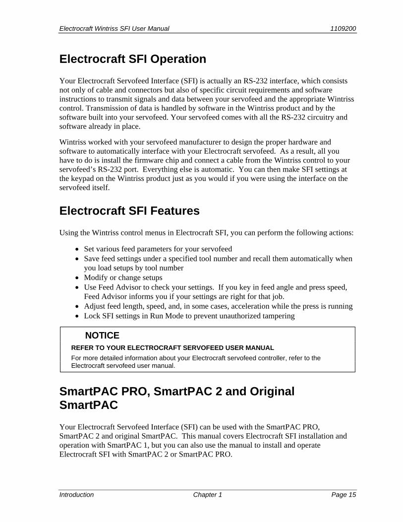
Electrocraft SFI Features Using the Wintriss control menus in Electrocraft SFI, you can perform the following actions:
• Set various feed parameters for your servofeed • Save feed settings under a specified tool number and recall them automatically when
you load setups by tool number • Modify or change setups • Use Feed Advisor to check your settings. If you key in feed angle and press speed,
Feed Advisor informs you if your settings are right for that job. • Adjust feed length, speed, and, in some cases, acceleration while the press is running • Lock SFI settings in Run Mode to prevent unauthorized tampering
REFER TO YOUR ELECTROCRAFT SERVOFEED USER MANUAL For more detailed information about your Electrocraft servofeed controller, refer to the
Electrocraft servofeed user manual.
SmartPAC PRO, SmartPAC 2 and Original SmartPAC Your Electrocraft Servofeed Interface (SFI) can be used with the SmartPAC PRO, SmartPAC 2 and original SmartPAC. This manual covers Electrocraft SFI installation and operation with SmartPAC 1, but you can also use the manual to install and operate Electrocraft SFI with SmartPAC 2 or SmartPAC PRO.
NOTICE

1109200 Electrocraft Wintriss SFI User Manual
Page 16 Chapter 1 Introduction
To install Electrocraft SFI on SmartPAC 2 or SmartPAC PRO, follow the instructions in Chapter 2, referring to the appropriate wiring diagrams at the end of the manual. (Wiring diagrams show connections for SmartPAC 1, SmartPAC 2, and SmartPAC PRO.) For Electrocraft SFI operation with SmartPAC 2 or SmartPAC PRO, follow the instructions in chapters 3-6.
Electrocraft SFI menu organization in SmartPAC 2 and SmartPAC PRO is similar to that in SmartPAC 1, and Electrocraft SFI screens are virtually the same in all SmartPACs. As a result, you can refer to the screens and follow the steps provided in chapters 3-6 of this manual to initialize, program, run, and troubleshoot Electrocraft SFI in SmartPAC 1, SmartPAC 2, and SmartPAC PRO. The main differences among the three SmartPACs are in their panel displays, as shown in Figure 1-1 and Figure 1-2.

Electrocraft Wintriss SFI User Manual 1109200
Introduction Chapter 1 Page 17
Figure 1-1. Panel Displays, SmartPAC 2 and Original SmartPAC
Figure 1-2. Panel Display, SmartPAC PRO
1
4
7
2 3
5 6
8 9
0 .CLEAR
Contrast
CURSOR
INTERRUPTEDSTROKE
BRAKEWARNING
ENTER
RESET
F1
F2
F3
F4
F5
F6
Wintriss Press Automation ControlSmartPAC
PROG RUN
ENABLE SENSORSCOUNTERSBRAKE MONITORDIE PROTECTIONCAM SWITCHTOOL INFORMATIONERROR LOGLOAD NEW TOOL
USE THE CURSOR KEYSTO MAKE SELECTIONS.PRESS ENTER TOACCESS SELECTION
TOOL NUMBER 6160 PART CNTR 0CHAIR BRACKET
ENABLE SENSORS
ENTER
RESET
PROG RUN
OFF
INCH
SINGLESTROKE
CONT
POWER
BRAKEWARNING
HELP
1 2 34 5 6
987.0CLEAR
SmartPAC 2F1
F2
F3
F4
F5
F6
F7
F8
CAMBIEAL ESPANOL
USE THE CURSOR KEYS ENABLE SENSORSTO MAKE SELECTIONS. COUNTERSPRESS ENTER TO CAM SWITCHACCESS SELECTION. BRAKE MONITOR
TONNAGE/WAVEFORMPROCESS MONITORFEED CONTROLPM MONITORTOOL INFORMATIONSHUTHGT/CNTRBALERROR LOGLOAD NEW TOOLDIALOG MENUTOGGLE HOT KEYS 1
330
PRESS # 14TOOL NUMBER 6160 PART CNTR 0FLANGE TWO HAND S.S.
PRESS ANGLE 330
Crank angle/SPM display
8 Function keys 6 Function keys
Help keySmartPAC 2
only
Contrast keysoriginal SmartPAC
only
SmartPAC 2 Original SmartPAC
SmartPAC PRO Help key
8 Function keys
Crank angle/ SPM display

1109200 Electrocraft Wintriss SFI User Manual
Page 18 Chapter 1 Introduction
SmartPAC 1, SmartPAC 2, and SmartPAC PRO panel displays use a different number of function, or “F,” keys. SmartPAC 2 and SmartPAC PRO have eight function keys, and the original SmartPAC only six. Be sure to read the instructions on the display and the descriptive labels on or next to the function keys before you press an “F” key.
On many screens, you can press the HELP key (see figures 1-1 and 1-2) to display instructions
showing you how to use the screen.
If you need additional help using Electrocraft SFI with SmartPAC 2 or SmartPAC PRO, refer to the appropriate user manual:
• SmartPAC 2 (1126700)
• SmartPAC 2 with WPC (1126800)
• SmartPAC 2 with WPC 2000 (1128600)
• SmartPAC PRO (1143100)
• SmartPAC PRO with WPC 2000 (1143300)
NOTICE

Electrocraft Wintriss SFI User Manual 1109200 Electrocraft SFI Installation Chapter 2 Page 19
Chapter 2 Electrocraft SFI Installation
This chapter shows you how to install the components that allow your SmartPAC or Wintriss 1500 series control to operate your Electrocraft servofeed. The chapter provides instructions for installing SFI firmware in the applicable Wintriss control and making wiring connections between the Electrocraft servofeed controller and the Wintriss control.
Wiring diagrams are provided at the back of the manual.
ELECTROCRAFT SFI AND SMARTPAC 2 AND SMARTPAC PRO You can use Electrocraft SFI with SmartPAC 2 and SmartPAC PRO as well as with the original
SmartPAC. Instructions provided in this manual that are specific to SmartPAC pertain to SmartPAC 1, SmartPAC 2, and SmartPAC PRO (refer to “SmartPAC PRO, SmartPAC 2 and Original SmartPAC,” page 15, for more information). Wiring diagrams at the back of the manual show pin connections for the different SmartPACs.
If you need further help in installing firmware or wiring your Wintriss control, consult the applicable Wintriss user manual.
Installing Electrocraft SFI in SmartPAC This section shows you how to install Electrocraft SFI in a SmartPAC control. Before starting, make sure you have the following parts:
• SFI firmware (unless factory-installed at time of order) • 20-foot 3-conductor shielded cable with DB-9 (part no. 4199106) or DB-15 (part no.
4199108) connector attached at one end • 10-pin Phoenix connector
NOTICE

1109200 Electrocraft Wintriss SFI User Manual
Page 20 Chapter 2 Electrocraft SFI Installation
Installing Electrocraft SFI Firmware in SmartPAC
For instructions on how to install upgraded firmware for Electrocraft SFI in SmartPAC PRO, refer to the SmartPAC PRO Firmware Update instructions which accompanies all SmartPAC PRO firmware orders.
To install Electrocraft IQ or Electrocraft BRU SFI firmware in SmartPAC, perform these steps:
ELECTRIC SHOCK HAZARD • Ensure that the power source is off before you replace electronic components in a control. • Disconnect power from the machinery it is connected to before replacing electronic
components. This includes disconnecting power to the machine control and motor. • Ensure that servicing is performed by qualified personnel. Failure to comply with these instructions could result in death or serious injury.
1. Turn off power to SmartPAC. The LCD on the front panel should be blank and the Angle/RPM display should be unlit.
DAMAGE TO BOARD FROM STATIC DISCHARGE Ground yourself before touching circuit boards or chips by touching a large metal object
such as the press. Static electricity can destroy electronic components. Failure to comply with these instructions could result in property damage.
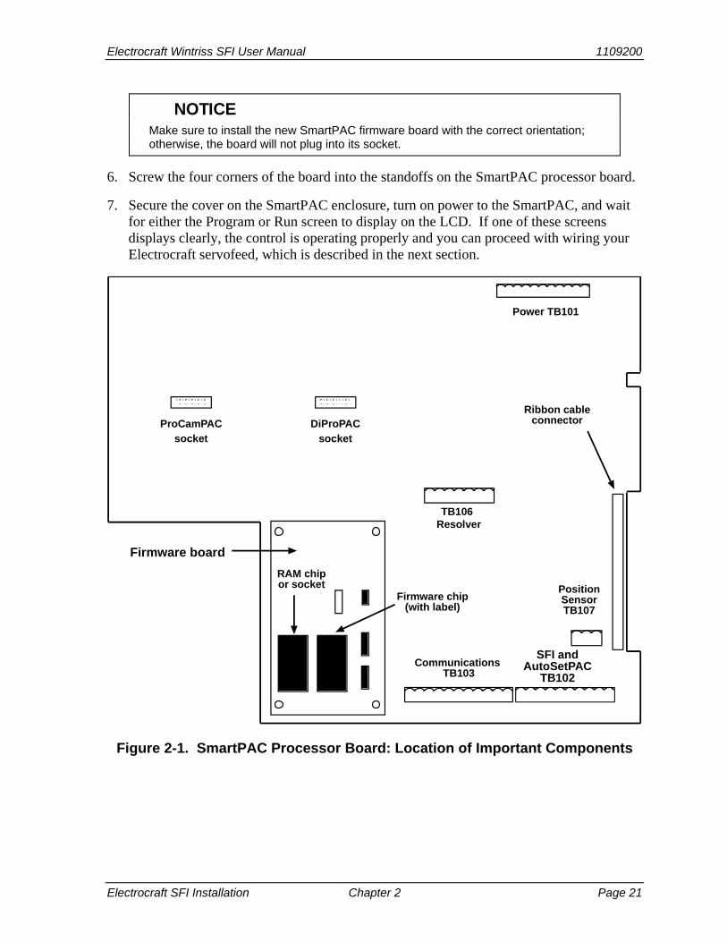
2. Making sure that you are grounded, open the SmartPAC enclosure and find the SmartPAC firmware board, which is located in the lower left corner of the SmartPAC processor board (see Figure 2-1).
3. Remove the four screws holding the firmware board to the standoffs on the SmartPAC processor board and put them aside.
4. Unplug the old SmartPAC firmware board from the SmartPAC processor board and put it aside so it will not be confused with the new SmartPAC firmware board.
The white label on the firmware chip on the SmartPAC firmware board (see Figure 2-1)
provides SmartPAC firmware identification information, including version number.
5. Remove the new SmartPAC firmware board from its package and plug it into the SmartPAC processor board so that the RAM and firmware chips are at the bottom, as shown in Figure 2-1.
NOTICE
WARNING!
CAUTION
NOTICE
Electrocraft Wintriss SFI User Manual 1109200
Electrocraft SFI Installation Chapter 2 Page 21
Make sure to install the new SmartPAC firmware board with the correct orientation;
otherwise, the board will not plug into its socket.
6. Screw the four corners of the board into the standoffs on the SmartPAC processor board.
7. Secure the cover on the SmartPAC enclosure, turn on power to the SmartPAC, and wait for either the Program or Run screen to display on the LCD. If one of these screens displays clearly, the control is operating properly and you can proceed with wiring your Electrocraft servofeed, which is described in the next section.
Figure 2-1. SmartPAC Processor Board: Location of Important Components
NOTICE
Power TB101
ProCamPACsocket
DiProPACsocket
TB106 Resolver
PositionSensorTB107
Ribbon cableconnector
Firmware board
Firmware chip(with label)
Communications TB103
RAM chipor socket
SFI andAutoSetPAC
TB102

1109200 Electrocraft Wintriss SFI User Manual
Page 22 Chapter 2 Electrocraft SFI Installation
Figure 2-1A. SmartPAC 2 Processor Board: Location of Important Components
TB101 RESOLVER
S101
TB105
TB106
TB102
TB104 TB103
AUX I/O
A B
JP101
JP102
SPEED
LOW
HIGH
INPUTCHECKSWITCH
1 1
1
1 1
1
1ProCam DiPro
PACNETSPECIAL MODULESFI
E-STOPRELAYS
POSITIONSENSOR LED
DS101
USB PORTLEDS
TOP STOPLED DS106
POWERLEDS
ETHERNET
ETHERNET LEDS LINK ACTIVITY
USB
INPUTCHECK
LEDDS103
E-STOPLEDS
COMPACTFLASHACCESS LED
K101 K102
F101 F102 F103
INPUT CHECKFUSE
E-STOPFUSE
TOP STOPFUSE
224 225 226 227 228 229 230 231 232 233 234
245 246 247 248 249 250 251 252 253 254212 213 214 215 216 217 218
TB107
235 236 237 238 239 240 241 242 243 244
205 206 207 208 209 210
PS/2
ZERO CAMLED DS102
TOPSTOP
RELAY
+BATTERY
Tx6Rx6
Tx5Rx5
Tx8Rx8
Tx7Rx7
MASTER
SLAVE

Electrocraft Wintriss SFI User Manual 1109200
Electrocraft SFI Installation Chapter 2 Page 23
Figure 2-1B. SmartPAC PRO Processor Board: Location of Terminal Blocks
If the unit powers up with a garbled display, turn the power off and check to make sure that the board is properly seated.
Some firmware upgrades cause SmartPAC to generate a tool number checksum error the first time you try to reload tool setups. If you get a checksum error after installing a new firmware board, enter Program mode and change one of the counters for that tool. Then reload the tool. If the unit still malfunctions, contact Wintriss Tech. Support.
Wiring the Electrocraft Feed Controller to SmartPAC
This section provides instructions for wiring the following Electrocraft feed controllers to SmartPAC:
• Electrocraft IQ (requires Electrocraft IQ SFI firmware) • Electrocraft BRU with Exor terminal (requires Electrocraft IQ SFI firmware) • Electrocraft BRU (requires Electrocraft BRU SFI firmware)
NOTICE

1109200 Electrocraft Wintriss SFI User Manual
Page 24 Chapter 2 Electrocraft SFI Installation
Be sure you have verified that SmartPAC is working properly before you proceed.
WIRING FOR YOUR SPECIFIC ELECTROCRAFT FEED MODEL Figures at the back of the manual provide wiring schematics for the following Electrocraft
servofeeds and SmartPAC 1/SmartPAC 2/SmartPAC PRO: • Figure 1: Electrocraft IQ servofeed • Figure 2: Electrocraft BRU servofeed with Exor terminal • Figure 3: Electrocraft BRU servofeed For additional information, consult your Electrocraft feed controller manual.
ELECTRIC SHOCK HAZARD • Ensure that the power source is off before you touch any wiring inside the enclosure. • Disconnect power from the machinery it is connected to before making any wiring connections.
This includes disconnecting power to the machine control and motor. • Ensure that servicing is performed by qualified personnel. Failure to comply with these instructions could result in death or serious injury.
1. Verify that SmartPAC and your feed are turned off.
2. Locate the black, round cable with a male DB-9 (Wintriss part no. 4199106) or DB-15 (Wintriss part no. 4199108) connector on one end. The other end of the cable has three unattached wires (white, red, black) and a shield.
The male DB-9 connector is used with Electrocraft IQ and BRU servofeeds (see Figures 1 and 3 at the back of the manual). The male DB-15 connector is used with the Electrocraft BRU servofeed with the Exor terminal (see Figure 2).
3. Open the SmartPAC enclosure and locate terminal TB102 on the SmartPAC processor board (see Figure 2-1) or TB103 on the SmartPAC 2 board (see Figure 2A), or TB6 on the SmartPAC PRO board (see Figure 2B).
SmartPAC is rated NEMA 12 (protected against dust and oil). You must use conduit of
the same rating and make proper connections to ensure NEMA 12 protection.
4. Locate the appropriate RS-232 port on your Electrocraft feed controller. RS-232 ports for each Electrocraft model are shown below:
Electrocraft IQ: P6–serial port 2 Electrocraft BRU with Exor terminal: PC/Printer port Electrocraft BRU: port J5
NOTICE
WARNING!
NOTICE

Electrocraft Wintriss SFI User Manual 1109200
Electrocraft SFI Installation Chapter 2 Page 25
5. Run the cable with the DB-9 or DB-15 connector through dedicated, flexible, liquid-tight conduit from your feed to SmartPAC.
6. Plug the DB-9 or DB-15 connector into the appropriate RS-232 port of your Electrocraft servofeed. Connectors and RS-232 ports for each Electrocraft model are shown below:
Electrocraft IQ: DB-9, P6–serial port 2 Electrocraft BRU with Exor terminal: DB-15, PC/Printer port Electrocraft BRU: DB-9, port J5
The connector can go in only one way. Tighten the screws on the connector to hold it firmly in its socket. Also tighten all conduit connections.
7. At SmartPAC, cut off any extra cable (a 1-foot service loop is recommended), and carefully remove the outer insulation and inner shielding on the cable to a distance that allows the shield drain wire to be connected to a ground stud near the cable entry point and the three conductors to be connected to TB102 on the SmartPAC 1 processor board, TB103 on the SmartPAC 2 board, or TB6 on the SmartPAC PRO board (see the wiring diagrams at the end of the manual).
8. Cut off any extra drain wire, then connect the drain wire to a ground stud near the cable’s point of entry by loosening the nut on the ground stud, wrapping the drain wire once clockwise around the stud, and tightening down the nut.
9. Strip insulation back 1/4” on the white, red, and black conductors, and connect the exposed wires at the SmartPAC end of the cable to the 10-pin Phoenix connector that plugs into terminal TB102 on the SmartPAC processor board, TB103 on the SmartPAC 2 board, or TB6 on the SmartPAC PRO board. as shown in the figures at the back of the manual. The appropriate figure for each Electrocraft servofeed is shown below:
Electrocraft IQ: Figure 1 Electrocraft BRU with Exor terminal: Figure 2 Electrocraft BRU: Figure 3
To connect a wire, loosen the screw in your Phoenix plug, insert the bare part of the wire 90% of the way into the open slot, and retighten the screw, holding the wire firmly in place (see Figure 2-2).

1109200 Electrocraft Wintriss SFI User Manual
Page 26 Chapter 2 Electrocraft SFI Installation
Figure 2-2. Attaching Wires to a Phoenix Connector (6-Pin Connector Shown)
When making wiring connections, be sure that the tab is tightened onto the bare part of
the wire, not onto the insulation. If it is on the insulation, you will have a bad connection.
10. Add a jumper between terminals 235 and 240 on the 10-pin Phoenix connector.
11. Plug the 10-pin connector into TB102 on the SmartPAC board, TB103 on the SmartPAC 2 board, or TB6 on the SmartPAC PRO board (see the wiring diagrams at the end of the manual).
12. Secure the cover on the SmartPAC enclosure.
13. Turn power back on to both SmartPAC and your servofeed.
14. Check that SmartPAC is operating normally. If it is, you are now ready to use Electrocraft SFI. Go to the next chapters to learn how to set up and operate your feed through SmartPAC.
If SmartPAC powers up with a garbled display, turn the power off and recheck how you
installed your firmware. Review “Installing Electrocraft SFI Firmware in SmartPAC,” page 20. If the unit is still malfunctioning and you cannot find the reason for the problem, call Wintriss Tech. Support for assistance.
Installing Electrocraft SFI in a 1500 Series Control This section shows you how to install Electrocraft SFI in a Wintriss 1500 series control (i.e., ProCam 1500 or DiPro 1500). Before starting, make sure you have the following parts:
• SFI firmware (unless factory-installed at time of order) • 20-foot 3-conductor shielded cable with DB-9 (part no. 4199106) or DB-15 (part no.
4199108) connector attached at one end • 10-pin Phoenix connector
insert wire here
tighten screw to clampwire in terminal
NOTICE
NOTICE

Electrocraft Wintriss SFI User Manual 1109200
Electrocraft SFI Installation Chapter 2 Page 27
Installing Electrocraft SFI Firmware in a 1500 Series Control
To install Electrocraft IQ or Electrocraft BRU SFI firmware in a Wintriss 1500 series control, perform these steps:
ELECTRIC SHOCK HAZARD • Ensure that the power source is off before you replace electronic components in a control. • Disconnect power from the machinery it is connected to before replacing electronic
components. This includes disconnecting power to the machine control and motor. • Ensure that servicing is performed by qualified personnel. Failure to comply with these instructions could result in death or serious injury.
1. Turn off power to the 1500 control. The LCD on the front panel should be blank and the Angle/RPM display should be unlit.
Ground yourself before touching circuit boards or chips by touching a large metal object
such as the press. Static electricity can destroy electronic components. Failure to comply with these instructions could result in damage to the electronics.
2. Making sure that you are grounded, open the 1500 enclosure and find the firmware chip on the processor board (see Figure 2-3, next page, for chip location on the ProCam 1500 processor board and Figure 2-4, page 29, for chip location on the DiPro 1500 processor board). Note the orientation of the notch on the chip.
The new firmware chip must be installed with the notch in the same orientation as the
old firmware chip. • On the ProCam 1500 processor board, the notch on the firmware chip must face up. • On the DiPro 1500 processor board, the notch on the firmware chip must face down.
DAMAGE TO PC BOARD Insert the screwdriver between the chip and the socket. Be careful not to insert the
screwdriver under the socket. You may damage the board. Failure to comply with these instructions could result in property damage.
3. Insert a small screwdriver between the bottom of the firmware chip and its socket and carefully pry the old chip from the board. Put the old chip aside so that it will not be confused with the new firmware chip.
WARNING!
CAUTION
NOTICE
CAUTION

1109200 Electrocraft Wintriss SFI User Manual
Page 28 Chapter 2 Electrocraft SFI Installation
Figure 2-3. ProCam 1500 Processor Board: Location of Important Components
(Back Side of Panel Mount)
Power TB104
RAMChip
TB106 Resolver
TB101
Communications TB103 Cam Output TB102
Firmwarechip
(with label)

Electrocraft Wintriss SFI User Manual 1109200
Electrocraft SFI Installation Chapter 2 Page 29
Figure 2-4. DiPro 1500 Processor Board: Location of Important Components
Power TB104
RAMChip
TB106 Resolver
Ribbon cableconnector
Communications TB103 Cam Output TB102
Firmwarechip
(with label)
DiPro InputTB101

1109200 Electrocraft Wintriss SFI User Manual
Page 30 Chapter 2 Electrocraft SFI Installation
The white label on the firmware chip provides ProCam 1500 (see Figure 2-3) or DiPro
1500 (see Figure 2-4) firmware identification information, including version number.
4. Open the package containing the new firmware chip and remove the chip from its holder.
WRONG INSTALLATION DAMAGES CHIP Install the chip with the notch facing in the same direction as the notch on the chip you
just removed; otherwise, when you power up the control, the chip will be destroyed. • On the ProCam 1500 processor board, the notch on the firmware chip must face up. • On the DiPro 1500 processor board, the notch on the firmware chip must face down. Failure to comply with these instructions could result in property damage.
5. Plug the chip into the firmware socket, inserting the left row of pins first, then aligning the right row of pins over the socket and pushing them in. Make sure that the notch in the chip faces in the correct direction (i.e., up for ProCam 1500, down for DiPro 1500) and that all of the pins are in the socket.
If the two rows of pins are spread too far apart to plug easily into the socket, hold the
chip on its side on a flat surface with the pins pointing toward you. Being careful not to overbend the pins, gently draw the top of the chip toward you until
the pins bend a little. Turn the chip over so that the other row of pins is now flat and pointing toward you. Draw the top of the chip toward you again until the pins bend.
When the rows of pins look parallel, plug the chip into its socket again. If the chip still doesn’t fit, repeat this procedure.
6. Secure the cover or face plate on the 1500 unit, turn on power to the 1500, and wait for either the Program or Run screen to display on the LCD. If one of these screens displays clearly, the control is operating properly and you can proceed with wiring your Electrocraft servofeed, which is described in the next section.
If the unit powers up with a garbled display, one or more pins may be bent or not plugged in properly. To correct this problem, turn the power off and repeat the procedure described in the Notice for step 5. If the unit continues to malfunction, call Wintriss Tech. Support.
NOTICE
CAUTION
NOTICE

Electrocraft Wintriss SFI User Manual 1109200
Electrocraft SFI Installation Chapter 2 Page 31
Wiring the Electrocraft Feed Controller to a 1500 Series Control
This section provides instructions for wiring the following Electrocraft feed controllers to a Wintriss 1500 series control:
• Electrocraft IQ (requires Electrocraft IQ SFI firmware) • Electrocraft BRU with Exor terminal (requires Electrocraft IQ SFI firmware) • Electrocraft BRU (requires Electrocraft BRU SFI firmware)
Be sure you have verified that your 1500 series control is working properly before you proceed.
WIRING FOR YOUR SPECIFIC ELECTROCRAFT FEED MODEL Figures at the back of the manual provide wiring schematics for the following Electrocraft
servofeeds and SmartPAC 1/SmartPAC 2/SmartPAC PRO: • Figure 4: Electrocraft IQ servofeed • Figure 5: Electrocraft BRU servofeed with Exor terminal • Figure 6: Electrocraft BRU servofeed For additional information, consult your Electrocraft feed controller manual.
1. Verify that the 1500 series control and your feed are turned off.
2. Locate the black, round cable with a male DB-9 (Wintriss part no. 4199106) or DB-15 (Wintriss part no. 4199108) connector on one end. The other end of the cable has three unattached wires (white, red, and black) and a shield.
The male DB-9 connector is used with Electrocraft IQ and BRU servofeeds (see Figures 4 and 6 at the back of the manual). The male DB-15 connector is used with the Electrocraft BRU servofeed with the Exor terminal (see Figure 5).
3. Open the 1500 enclosure and locate terminal TB103 on the ProCam 1500 or DiPro 1500 processor board (see Figure 2-3 or Figure 2-4).
ProCam 1500 and DiPro 1500 are rated NEMA 12 (protected against dust and oil). You
must use conduit of the same rating and make proper connections to ensure NEMA 12 protection.
4. Locate the appropriate RS-232 port on your Electrocraft feed controller. RS-232 ports for each Electrocraft model are shown below:
Electrocraft IQ: P6–serial port 2 Electrocraft BRU with Exor terminal: PC/Printer port Electrocraft BRU: port J5
NOTICE
NOTICE

1109200 Electrocraft Wintriss SFI User Manual
Page 32 Chapter 2 Electrocraft SFI Installation
5. Run the cable with the DB-9 or DB-15 connector through dedicated, flexible, liquid-tight conduit from your feed to the 1500 control.
6. Plug the DB-9 or DB-15 connector into the appropriate RS-232 port of your Electrocraft servofeed. Connectors and RS-232 ports for each Electrocraft model are shown below:
Electrocraft IQ: DB-9, P6–serial port 2 Electrocraft BRU with Exor terminal: DB-15, PC/Printer port Electrocraft BRU: DB-9, port J5
The connector can go in only one way. Tighten the screws on the connector to hold it firmly in its socket. Also tighten all conduit connections.
7. At the 1500 control, cut off any extra cable (a 1-foot service loop is recommended), and carefully remove the outer insulation and inner shielding on the cable to a distance that allows the shield drain wire to be connected to a ground stud near the cable entry point and the three conductors to be connected to TB103 on the ProCam 1500 or DiPro 1500 processor board.
8. Cut off any extra drain wire, then connect the drain wire to a ground stud near the cable’s point of entry by loosening the nut on the ground stud, wrapping the drain wire once clockwise around the stud, and tightening down the nut.
9. Strip insulation back 1/4” on the white, red, and black conductors, and connect the exposed wires at the 1500 control end of the cable to the 10-pin Phoenix connector that plugs into terminal TB103 on the ProCam 1500 or DiPro 1500 processor board. Refer to the appropriate figure at the back of the manual for specific wiring connections for your Electrocraft servofeed model, as shown below:
Electrocraft IQ: Figure 4 Electrocraft BRU with Exor terminal: Figure 5 Electrocraft BRU: Figure 6
To connect a wire (see Figure 2-2, page 26), loosen the screw on the plug, insert the
bare part of the wire 90% of the way into the open slot, then retighten the screw, holding the wire firmly in place.
When making wiring connections, be sure that the tab is tightened onto the bare part of the wire, not onto the insulation. If it is on the insulation, you will have a bad connection.
10. Add a jumper to the 10-pin Phoenix connector:
• For ProCam 1500: jumper between terminal pins 3 and 6 • For DiPro 1500: jumper between terminal pins 3 and 10
11. Plug the 10-pin connector back into TB103 on the ProCam 1500 or DiPro 1500 processor board.
NOTICE

Electrocraft Wintriss SFI User Manual 1109200
Electrocraft SFI Installation Chapter 2 Page 33
12. Secure the cover or face plate on the 1500 unit.
13. Turn power back on to both the 1500 control and to your servofeed.
14. Check that the 1500 unit is operating normally. If it is, you are now ready to use Electrocraft SFI. Go to the next chapters to learn how to set up and operate your feed through the 1500 series control.
If your 1500 control powers up with a garbled display, turn the power off and recheck
how you installed your firmware. Review “Installing Electrocraft SFI Firmware in a 1500 Series Control,” page 27. If the unit is still malfunctioning and you cannot find the reason for the problem, call Wintriss Tech. Support for assistance.
NOTICE

Electrocraft Wintriss SFI User Manual 1109200 Electrocraft SFI Initialization Mode Chapter 3 Page 34
Chapter 3 Electrocraft SFI Initialization Mode
This chapter shows you how to set several feed initialization parameters in Electrocraft SFI Initialization mode. Instructions are provided for both SmartPAC and Wintriss 1500 series controls.
ELECTROCRAFT SFI AND SMARTPAC 1, SMARTPAC 2, AND SMARTPAC PRO You can use Electrocraft SFI with SmartPAC 2 and SmartPAC PRO as well as with the original
SmartPAC. Instructions provided in this manual that are specific to SmartPAC pertain to SmartPAC 1, SmartPAC 2, and SmartPAC PRO (refer to “SmartPAC PRO, SmartPAC 2 and Original SmartPAC,” page 3, for more information). Wiring diagrams at the back of the manual show pin connections for the different SmartPACs.
If you need additional help using Initialization mode in SmartPAC or 1500 series controls, refer to the applicable Wintriss user manual. For more information about your Electrocraft servofeed, refer to the appropriate Electrocraft servofeed manual.
Initializing Electrocraft SFI in SmartPAC
READ YOUR ELECTROCRAFT SERVOFEED MANUAL BEFORE MAKING ANY SETTINGS! Make sure you have read the appropriate Electrocraft servofeed manual and understand how
your servofeed works before making any changes to Initialization settings.
To get into Initialization mode in SmartPAC, turn the Program/Run key to “PROG” and then press both the “1” and “CLEAR” keys at the same time for one second. (See “Using the Keyboard” in Chapter 3 of the SmartPAC user manual.)
Initialization Menu
Before changing modes (from Initialization to Program, for instance), make sure your screen
shows the first display in the sequence of displays for the mode you are in. If the first display does not appear on the screen, nothing will happen when you turn the Program/Run key. To return to the first display, press the RESET key repeatedly. Then turn the Program/Run key to switch to the new mode.
NOTICE
NOTICE
NOTICE

Electrocraft Wintriss SFI User Manual 1109200
Electrocraft SFI Initialization Mode Chapter 3 Page 35
SELECT = HIGHLIGHT + ENTER When you are instructed in this manual to “select” a menu item, press the Up (▲) or Down (▼)
cursor key on the Wintriss control keypad to highlight the item, then press the ENTER key.
The first display in Initialization mode (the order of items may vary depending on installed options) is shown in Figure 3-1. On this display, select “FEED CONTROL.”
Figure 3-1. SmartPAC Main Initialization Menu with “FEED CONTROL” Selected
Initializing Feed Control Parameters
When you select “FEED CONTROL,” the Feed Control Initialization Parameters screen displays. The items shown on this screen differ depending on the firmware you are running and the Electrocraft model you are using. These differences are covered in the following sections.
Electrocraft IQ
If you have installed Electrocraft IQ firmware, the Feed Control Initialization Parameters screen looks like the example shown in Figure 3-2, next page. This screen allows you to set Units Type, Settling Time, Connection Type, Baud Rate, and Acceleration Units.
Units Type allows you to set SmartPAC’s units of measurement to either inches or metric units. The default is “INCHES.” To change the setting to “METRIC,” press ENTER with “INCHES” highlighted.
Information appearing in figures in this manual will be displayed in “inches” unless the value can
only be expressed in metric units.
NOTICE
NOTICE

1109200 Electrocraft Wintriss SFI User Manual
Page 36 Chapter 3 Electrocraft SFI Initialization Mode
Figure 3-2. Feed Control Initialization Parameters Screen: Electrocraft IQ
Settling Time refers to the amount of time (in milliseconds) that it takes for the feed to settle down at its precise feed length position at the end of a feed cycle. Settling Time also refers to the time it takes the feed control to sense that the feed signal is present. Figure 3-2 shows a Settling Time value of 20 milliseconds as an example. For assistance in selecting the appropriate value, consult your Electrocraft user manual.
To change Settling Time, press ENTER with the Settling Time value highlighted. When the Numeric Entry window displays, follow the directions provided to enter a new Settling Time value. Use the number keys to input a new value or the Up (▲) or Down (▼) cursor key to increment or decrement the current value. When you are done, press ENTER. SmartPAC will accept the number and move on to the next display.
Connection Type specifies whether you want SmartPAC to automatically store in memory changes you make at the Electrocraft feed controller. There are two settings. “WITH UPLOAD” indicates that changes made at the feed controller are automatically stored with the tool number. “NO UPLOAD” indicates that the operator has to reload the tool setup in order for SmartPAC to accept changes at the feed control. To move back and forth between the two settings, press the ENTER key.
Baud Rate is the communication speed between the Electrocraft feed controller and the SmartPAC. To select a value, press ENTER to cycle through the available settings until the one you want is displayed.
Acceleration Units specifies the units of measurement that will be used to display acceleration ramp time or acceleration percent in Program mode. There are three settings: MSECS, SECS, and %. The “%” setting is used only if you are setting Initialization parameters for an Electrocraft BRU controller with an Exor terminal (see next section). For Electrocraft IQ controllers, use the ENTER key to select either MSEC or SEC. Electrocraft will display acceleration ramp time in Program mode in the units you have specified.

Electrocraft Wintriss SFI User Manual 1109200
Electrocraft SFI Initialization Mode Chapter 3 Page 37
When you are finished entering feed control initialization parameters, press the RESET key to return to the Main Initialization Menu.
For additional information about Units Mode, Settling Time, Connection Type, Baud Rate, and Accel Units, refer to the Electrocraft user manual.
Electrocraft BRU with Exor Terminal
If you are running Electrocraft IQ firmware and you are making Initialization settings for a BRU controller with an Exor terminal, you set Units Type, Settling Time, Connection Type, and Baud Rate just as you do for an IQ controller (see previous section). However, instead of selecting the MSEC or SEC setting for ACCEL UNITS, you select the “%” setting. When you do so, two additional fields display on the Feed Control Initialization Parameters screen, as shown in Figure 3-3.
Figure 3-3. Feed Control Initialization Parameters Screen: Electrocraft BRU with Exor Terminal
Acceleration Limit specifies the feed’s maximum rate of acceleration. Speed Limit specifies its maximum speed. For both fields, press ENTER with the field highlighted to display the Numeric Entry window, key in a value (1,000 maximum for Accel Limit, 9,999 maximum for Speed Limit), following the instructions in the window, and press ENTER again. The value you entered is displayed on the screen.
The acceleration and speed limits entered on this screen are used to calculate speed and acceleration percentages displayed in Program and Run modes.
Further information about Units Mode, Settling Time, Connection Type, Baud Rate, Accel. Units, Accel Limit., and Speed Limit, can be found in the Electrocraft user manual.
When you are finished entering feed control initialization parameters, press the RESET key to return to the Main Initialization Menu.

1109200 Electrocraft Wintriss SFI User Manual
Page 38 Chapter 3 Electrocraft SFI Initialization Mode
Electrocraft BRU
If you are running Electrocraft BRU firmware, the screen you see when you select FEED CONTROL on the SmartPAC Main Initialization Menu looks like the example shown in Figure 3-4. On this screen, you set Units Type and Settling Time just as you do for Electrocraft IQ or BRU/Exor models (see previous sections). You also make settings for Acceleration, Jog Speed, Kp Gain, Scale Factor, and Motor Direction.
Figure 3-4. Feed Control Initialization Parameters Screen: Electrocraft BRU
Acceleration specifies the feed’s rate of acceleration. To enter a value, highlight this field, press ENTER to display the Numeric Entry window, key in a value, following the directions in the window, and press ENTER again. The value you entered is displayed on the screen.
The remaining fields are entered in the same way. Consult you Electrocraft manual for definitions and settings as well as for additional information about Units Type, Settling Time, and Acceleration fields.
When you are finished entering feed control initialization parameters, press the RESET key to return to the Main Initialization Menu.
Locking Adjust Feed
You can prevent unauthorized personnel from unlocking “ADJUST FEED” and changing feed settings in Run mode. To do so, you must remove the Program/Run key when SmartPAC is switched to Run mode. Since the key must be positioned at “PROG” in order to access Initialization and Program modes, removing the key when SmartPAC is set to RUN prevents settings from being changed by unauthorized users.

Electrocraft Wintriss SFI User Manual 1109200
Electrocraft SFI Initialization Mode Chapter 3 Page 39
You must also enter a setting on the Security Access Menu. To do so, select “SECURITY ACCESS” from the Main Initialization Menu. When the Security Access Menu (see Figure 3-5, below) displays, select the “PROGRAM AND RUN MODES” item to the right of the “ADJUST FEED” action. This is the default setting made at the factory and allows feed adjustments to be made in both Program and Run modes.
Figure 3-5. SmartPAC Security Access Menu with Feed Adjustment Set for both Program and Run Modes
To lock out the “ADJUST FEED” action so that it cannot be taken in Run mode, press the ENTER key with “PROGRAM AND RUN MODES” highlighted. The item to the right of “ADJUST FEED” changes to “PROGRAM MODE ONLY,” as shown in Figure 3-6, indicating that the feed controller can now be adjusted in Program mode only.
Figure 3-6. SmartPAC Security Access Menu with Feed Adjustment Set for Program Mode Only

1109200 Electrocraft Wintriss SFI User Manual
Page 40 Chapter 3 Electrocraft SFI Initialization Mode
If you do not want to make a change, press RESET to return to the Main Initialization Menu.
Viewing Communications
The “COMMUNICATIONS” item on the Diagnostic Menu (see Figure 3-7, below) allows you to verify communications between SmartPAC and your Electrocraft feed controller. You access the Diagnostic Menu from the Main Initialization Menu (see Figure 3-1) by selecting “DIAGNOSTICS.”
Figure 3-7. COMMUNICATIONS Item on Diagnostic Menu in Initialization Mode
When you select “COMMUNICATIONS” on the Diagnostic Menu, the Communication Data Viewer screen, shown in Figure 3-8, displays.
Figure 3-8. SmartPAC Communication Data Viewer Screen
F1
F2
F3
F4
F5
F6
F7
F8

Electrocraft Wintriss SFI User Manual 1109200
Electrocraft SFI Initialization Mode Chapter 3 Page 41
Press the F1 function key on the Communication Data Viewer screen to change the F1 label from “Combined Tx and Rx” to “Split Tx and Rx,” then select “PORT 1 (SFI).” A screen like the one shown in Figure 3-9 will appear.
Figure 3-9. SmartPAC Communication Transmit/Receive Screen
If SmartPAC and the Electrocraft servofeed controller are communicating normally, you should expect to see some text (data) in both the “TRANSMIT BUFFER DATA” and “RECEIVE BUFFER DATA” portions of the screen. If you do not see any data (or only partial data), this means that SmartPAC and the servofeed controller are not communicating properly.
If there is a communications problem, you may decide to perform a loopback test. In a loopback test, you connect (or jumper) the TXD (Transmit) and RXD (Receive) lines (refer to Figure 7 at the end of this manual), and then press F1 to check communications. In effect, you are “receiving” the communications data that you are transmitting.
This test is useful when verifying the accuracy of the transmit and receive hardware and wiring. If you need help performing the loopback test, contact Wintriss Tech. Support.
data that appears here is being transmitted from SmartPAC
data that appears here is being transmitted from the servofeed controller
TRANSMIT BUFFER DATA
RECEIVE BUFFER DATA
1109200 Electrocraft Wintriss SFI User Manual
Page 42 Chapter 3 Electrocraft SFI Initialization Mode
Initializing Electrocraft SFI in a 1500 Series Control
READ YOUR ELECTROCRAFT SERVOFEED MANUAL BEFORE MAKING ANY SETTINGS! Make sure you have read the appropriate Electrocraft servofeed manual and understand how
your servofeed works before making any changes to Initialization settings.
Initialization Menu
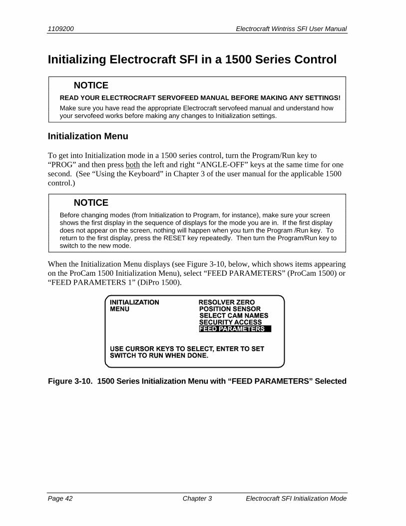
To get into Initialization mode in a 1500 series control, turn the Program/Run key to “PROG” and then press both the left and right “ANGLE-OFF” keys at the same time for one second. (See “Using the Keyboard” in Chapter 3 of the user manual for the applicable 1500 control.)
Before changing modes (from Initialization to Program, for instance), make sure your screen
shows the first display in the sequence of displays for the mode you are in. If the first display does not appear on the screen, nothing will happen when you turn the Program /Run key. To return to the first display, press the RESET key repeatedly. Then turn the Program/Run key to switch to the new mode.
When the Initialization Menu displays (see Figure 3-10, below, which shows items appearing on the ProCam 1500 Initialization Menu), select “FEED PARAMETERS” (ProCam 1500) or “FEED PARAMETERS 1” (DiPro 1500).
Figure 3-10. 1500 Series Initialization Menu with “FEED PARAMETERS” Selected
NOTICE
NOTICE

Electrocraft Wintriss SFI User Manual 1109200
Electrocraft SFI Initialization Mode Chapter 3 Page 43
Initializing Feed Control Parameters
Electrocraft IQ or Electrocraft BRU with Exor Terminal
If you have installed Electrocraft IQ firmware and are connected to an Electrocraft IQ controller or an Electrocraft BRU controller with an Exor terminal, the screen that displays when you select “FEED PARAMETERS” looks like the one shown in Figure 3-11. You use this screen to initialize the feed control parameters Units Mode, Settling Time, and Connection Type.
Figure 3-11. 1500 Series Feed Control Initialization Parameters Screen with “UNITS MODE” Selected (Electrocraft IQ or Electrocraft BRU/Exor)
Units Mode allows you to set the 1500 control’s units of measurement to either inches or metric units. The default is “INCHES.” To change the setting to “METRIC,” press ENTER with “INCHES” highlighted.
Information appearing in figures in this manual will be displayed in “inches” unless the value can
only be expressed in metric units.
Settling Time refers to the amount of time (in milliseconds) that it takes for the feed to settle down at its precise feed length position at the end of a feed cycle. Settling Time also refers to the time it takes the feed control to sense that the feed signal is present. Figure 3-11 shows a Settling Time value of 20 milliseconds as an example. For assistance in selecting the appropriate value, consult your Electrocraft user manual.
To change Settling Time, press ENTER with the Settling Time value highlighted, then use the Up (▲) or Down (▼) cursor key to increment or decrement the current value. When you are done, press ENTER. The 1500 control will accept the number and move on to the next display. The 1500 unit accepts numbers up to seven digits in length.
NOTICE

1109200 Electrocraft Wintriss SFI User Manual
Page 44 Chapter 3 Electrocraft SFI Initialization Mode
Connection Type specifies whether you want the 1500 unit to automatically store in memory changes you make at the Electrocraft feed controller. There are two settings. “WITH UPLOAD” indicates that changes made at the feed controller are automatically stored with the tool number. “NO UPLOAD” indicates that the operator has to reload the tool setup in order for the 1500 unit to accept changes at the feed control. To move back and forth between the two settings, press the ENTER key.
For additional help in setting feed control parameters, refer to the appropriate Electrocraft user manual.
When you are finished entering feed control initialization parameters, press the RESET key to return to the Initialization Menu.
Electrocraft BRU
If you are running firmware for an Electrocraft BRU controller, the screen that displays when you select “FEED PARAMETERS” looks like the one shown in Figure 3-12. In addition to allowing you to set Units Type and Settling Time, as you do for an Electrocraft IQ controller or an Electrocraft BRU controller with an Exor terminal (see previous section), this screen allows you to make settings for Acceleration, Jog Speed, Kp Gain, Scale Factor, and Motor Direction.
Figure 3-12. 1500 Series Feed Control Initialization Parameters Screen with “UNITS MODE” Selected (Electrocraft BRU)
Acceleration specifies the feed’s rate of acceleration. To change Acceleration, press ENTER with the Acceleration value highlighted, then use the Up (▲) or Down (▼) cursor key to increment or decrement the current value. When you are done, press ENTER. The 1500 control will accept the number and move on to the next display. The 1500 unit accepts numbers up to seven digits in length.
The remaining fields are entered in the same way. Consult you Electrocraft manual for definitions and settings as well as for additional information about Units Type, Settling Time, and Acceleration.
When you are finished entering feed control initialization parameters, press the RESET key to return to the Initialization Menu.

Electrocraft Wintriss SFI User Manual 1109200
Electrocraft SFI Initialization Mode Chapter 3 Page 45
Locking Adjust Feed
You can prevent unauthorized personnel from unlocking “ADJUST FEED” and changing feed settings in Run mode. To do so, you must remove the Program/Run key when ProCam 1500 or DiPro 1500 is switched to Run mode. Since the key must be positioned at “PROG” in order to access Initialization and Program modes, removing the key when ProCam or DiPro is set to RUN prevents settings from being changed by unauthorized users.
Locking Adjust Feed in ProCam 1500
In ProCam 1500, you must also enter a setting on the Security Access Menu. To do so, select “SECURITY ACCESS” from the Initialization menu to display the Security Access Menu, which is shown in Figure 3-13, below. Select the “PROGRAM AND RUN MODES” item to the right of the “ADJUST FEED” action. This is the default setting made at the factory and allows feed adjustments to be made in both Program and Run modes.
Figure 3-13. 1500 Series Security Access Menu with Feed Adjustment Set for both Program and Run Modes
To lock out the “ADJUST FEED” action so that it cannot be taken in Run mode, press the ENTER key with “PROGRAM AND RUN MODES” highlighted. The item to the right of “ADJUST FEED” changes to “PROGRAM MODE ONLY,” as shown in Figure 3-14, indicating that the feed controller can now be adjusted in Program mode only.
Figure 3-14. 1500 Series Security Access Menu with Feed Adjustment Set for Program Mode Only

1109200 Electrocraft Wintriss SFI User Manual
Page 46 Chapter 3 Electrocraft SFI Initialization Mode
If you do not want to make a change, press RESET to return to the Initialization menu.
Locking Adjust Feed in DiPro 1500
DIPRO 1500 AUTO ADVANCE AND SECURITY In DiPro 1500, “Auto Advance” and “Adjust Feed“ security are not main Initialization choices.
(SFI was not originally offered with DiPro 1500.) Instead, feed-specific selections are grouped under Feed Initialization. To change default “Auto Advance” and “Adjust Feed” settings, you must select the “Feed Parameters 2” item on the DiPro 1500 Initialization Menu (see Figure 3-15, below). Only DiPro 1500’s Channel 1 can be an auto advance channel with SFI.
Figure 3-15. DiPro 1500 Initialization Menu with “FEED PARAMETERS 2” Selected
You must also enter a setting on the DiPro 1500 Feed Control Initialization Parameters 2 screen. To do so, select FEED PARAMETERS 2 on the DiPro 1500 Initialization Menu (see Figure 3-15, above). The Feed Control Initialization Parameters 2 screen (see Figure 3-16, below) displays. Select the “PROGRAM AND RUN MODES” item to the right of the “ADJUST FEED” action. This is the default setting made at the factory and allows feed adjustments to be made in both Program and Run modes.
Figure 3-16. DiPro 1500 Feed Control Initialization Parameters 2 Screen with Feed Adjustment Set for both Program and Run Modes
NOTICE

Electrocraft Wintriss SFI User Manual 1109200
Electrocraft SFI Initialization Mode Chapter 3 Page 47
To lock out the “ADJUST FEED” action so that it cannot be taken in Run mode, press the ENTER key with “PROGRAM AND RUN MODES” highlighted. The item to the right of “ADJUST FEED” changes to “PROGRAM MODE ONLY,” indicating that the feed controller can now be adjusted in Program mode only.
If you do not want to make a change, press RESET to return to the DiPro 1500 Initialization Menu.
Auto Advance and Slow RPM in DiPro 1500
Calculating the Advance Constant for Channel 1 Automatic Speed Compensation
You use the “ADV. CONST. CH 1” selection on the Feed Parameters 2 Initialization screen to set an auto advance constant for the cam channel 1 auto advance function. Cam functions that may use auto advance are feed advance and pilot release. Auto advance works best on presses that have a speed range of several hundred to over a thousand strokes per minute.
The auto advance constant is equal to the number of degrees of advance per 100 RPM increase in press speed.
A.C. = # °/100 RPM
To calculate the auto advance constant for pilot release, follow these steps:
1. Determine the fastest press speed (RPMa) and the optimum angle at which the pilot release cam should turn on at this speed (Aa).
2. Determine the slowest press speed (RPMb) and the optimum angle at which the pilot release cam should turn on at this speed (Ab).
3. Subtract the two angle values. We will call this result “Ac.” Aa - Ab = Ac
4. Subtract the two press speeds. We will call this result “RPMc.” RPMa - RPMb = RPMc
5. Divide Ac (the difference between the angles) by RPMc (the difference between the press speeds), and multiply that value by 100. The result is the number of degrees per 100 RPM.
Ac x 100 = # ° / 100 RPM RPMc
Example: Calculating the Auto Advance Setting
Your fastest speed is 100 RPM and the pilot release angle at that speed is 75°.
Your slowest speed is 50 RPM and the pilot release angle at that speed is 100°.

1109200 Electrocraft Wintriss SFI User Manual
Page 48 Chapter 3 Electrocraft SFI Initialization Mode
Subtract 50 RPM from 100 RPM. 100 - 50 = 50
Subtract 75° from 100°. 100 - 75 = 25
Divide the difference in angles by the difference in RPM, and multiply the quotient by 100. The result is your advance constant–in this example, 50°.
25 x 100 = 50.00 ==> 50° / 100 RPM 50
MORE ON ADVANCE CONSTANT SETTINGS You can make only one auto advance constant setting. This setting will automatically be applied
to channel 1, but it will not be displayed as an “auto” setting in Program or Run modes. If you do not wish to use the Auto Advance feature, leave the “ADV. CONST. CH 1” setting at its
default value of zero (0). Auto Advance does not function if channel 1 has been programmed as a “timed output.” See
Chapter 5 in the DiPro 1500 user manual for more information about making cam channel settings.
Setting the Auto Advance Constant
To set the Auto Advance Constant, move the highlight bar to the “ADV. CONST. CH 1” item on the Feed Parameters 2 Initialization screen (see Figure 3-16), and press ENTER. The prompt displayed at the bottom of the screen will change, as shown in Figure 3-17.
Figure 3-17. DiPro 1500 Feed Control Initialization Parameters 2 Screen with “ADV. CONST. CH 1” Selected
As directed in the prompt, use the Up (▲) or Down (▼) cursor key on your DiPro 1500 keypad to increment or decrement the “ADV. CONST. CH. 1” value. The range for this value is 0-500.
NOTICE

Electrocraft Wintriss SFI User Manual 1109200
Electrocraft SFI Initialization Mode Chapter 3 Page 49
Setting Slow RPM
In calculating an auto advance constant, you must determine the slowest speed at which your press will operate. This value is entered in the “SLOW RPM” field on the Feed Parameters 2 Initialization screen. DiPro uses the “SLOW RPM” value as a starting point in the auto advance process. If an incorrect number is entered in the “SLOW RPM” field, DiPro will not begin to auto advance at the right time. In the example above, you would set slow RPM to 50.
To set Slow RPM, move the highlight bar to the “SLOW RPM” item on the Feed Parameters 2 Initialization screen, and press ENTER. Use the Up (▲) or Down (▼) cursor key on the DiPro 1500 keypad to increment or decrement the “SLOW RPM” value. The value increases or decreases 5 units for each depression of the Up (▲) or Down (▼) cursor key. The range for Slow RPM is 0-2000 RPM.

Electrocraft Wintriss SFI User Manual 1109200 Electrocraft SFI Program Mode Chapter 4 Page 50
Chapter 4 Electrocraft SFI Program Mode
This chapter shows you how to use Electrocraft SFI in Program mode. You will learn how to perform the following actions:
• Set feed parameters • Use the Feed Advisor • Load feed settings
ELECTROCRAFT SFI AND SMARTPAC 1, SMARTPAC 2, AND SMARTPAC PRO You can use Electrocraft SFI with SmartPAC 2 and SmartPAC PRO as well as with the original
SmartPAC. Instructions provided in this manual that are specific to SmartPAC pertain to SmartPAC 1, SmartPAC 2, and SmartPAC PRO (refer to “SmartPAC PRO, SmartPAC 2 and Original SmartPAC,” page 3, for more information). Wiring diagrams at the back of the manual show pin connections for the different SmartPACs.
If you need additional help with your Wintriss product, refer to the applicable Wintriss user manual. Refer to the appropriate Electrocraft servofeed manual for more information about your Electrocraft servofeed.
Using Electrocraft SFI Program Mode in SmartPAC
READ YOUR ELECTROCRAFT SERVOFEED MANUAL BEFORE MAKING ANY SETTINGS! Make sure you have read the appropriate Electrocraft servofeed manual and understand how
your servofeed works before making any settings.
About Tool Number
A tool number consists of all the programmed settings (including servofeed settings) that you make for one job. You can save servofeed information for up to 200 tools and then recall these settings for each job whenever you need to.
NOTICE
NOTICE

Electrocraft Wintriss SFI User Manual 1109200
Electrocraft SFI Program Mode Chapter 4 Page 51
Program Menu
You enter Program mode by turning the Program/Run key to “RUN” and then back to “PROG.” Next, select a tool number to modify, and then select “MODIFY THE TOOL NUMBER INFORMATION.” If you are not sure how to program a tool, refer to Chapter 5 in the SmartPAC user manual.
SELECT = HIGHLIGHT + ENTER When you are instructed in this manual to “select” a menu item, press the Up (▲) or Down (▼)
cursor key to highlight the item, then press the ENTER key. See Chapter 3 in the SmartPAC user manual for more information.
Once you have selected a tool, the Main Programming Menu, shown in Figure 4-1, below, will appear. The Main Programming Menu displays the various settings you can make for the selected tool (the order of items may vary depending on installed options).
Figure 4-1. SmartPAC Main Programming Menu with “FEED CONTROL” Selected
Select the “Feed Control” item, as shown in Figure 4-1. The Feed Parameters screen, shown in Figure 4-2, displays.
NOTICE

1109200 Electrocraft Wintriss SFI User Manual
Page 52 Chapter 4 Electrocraft SFI Program Mode
Figure 4-2. SmartPAC Feed Parameters Screen with “FEED LENGTH” Selected
The information displayed on the Feed Parameters screen, except for the Feed Length field (which is common to all Electrocraft SFI configurations), depends on the firmware you are running and the settings you have made in Initialization.
The screen shown in Figure 4-2 displays the fields you will see if you are running Electrocraft IQ firmware and have entered Initialization settings for an Electrocraft IQ controller.
If you are running Electrocraft IQ firmware and have entered Initialization settings for an Electrocraft BRU controller with an Exor terminal, the Feed Parameters screen will display Speed and Acceleration (not Acceleration Ramp Time) in addition to the Feed Length field, both values being shown as a percentage of the speed and acceleration limits you established in Initialization (see page 37).
If you are running Electrocraft BRU firmware and have set Initialization parameters for an Electrocraft BRU controller, the Feed Parameters screen displays only a Speed field, shown as a percentage of maximum speed, in addition to the Feed Length field.
Feed Settings
When you select each item shown, the Numeric Entry window displays, allowing you to set or change the value. Use the number keys to input a desired setting, or the Up (▲) or Down (▼) cursor key to increment or decrement a displayed value.
When you are done, press ENTER. SmartPAC will accept the number and move on to the next display. SmartPAC accepts numbers up to seven digits in length.

Electrocraft Wintriss SFI User Manual 1109200
Electrocraft SFI Program Mode Chapter 4 Page 53
If you need help using the number or cursor keys, refer to Chapter 3 in your SmartPAC user
manual.
Rather than inputting feed settings yourself, you can have Feed Advisor calculate settings for you. See the instructions in the next section to access the Feed Advisor.
If you wish to leave the Feed Parameters screen without making any changes, press RESET.
Feed Advisor
Feed Advisor is a convenience which saves you the time of calculating feed parameters yourself. When using Feed Advisor, you need to enter feed length, feed arc (number of crankshaft degrees available to fully feed the material), and press speed. When determining these parameters, take into consideration the feed initiate angle, which may be programmed as one of the cam timings in SmartPAC (not SFI).
Make sure that you know the actual number of degrees needed to feed up the material, and be careful to set the feed initiate angle correctly. Otherwise, you may endanger the die. For example, if a 225 degree feed arc is assumed in the Feed Advisor but only 220 degrees is truly available to be fed up, punch engagement may occur before the feed is complete and a die crash may occur.
Let’s say your feed length is 2.252 inches. Also, let’s say the number of degrees you have to feed in is 225° with the feed initiate ON angle set at 260°, and the press speed is 150 SPM. To use Feed Advisor to calculate run speed based on these values, proceed as follows.
Select “FEED ADVISOR” on the Feed Parameters screen (see Figure 4-2). The Servo Feed Advisor screen, shown in Figure 4-3, displays.
Figure 4-3. SmartPAC Servo Feed Advisor Screen with “FEED LENGTH” Selected
NOTICE
SERVO FEED ADVISOR
USE THE CURSOR KEYS TO SELECT THE VALUEYOU WANT TO CHANGE. PRESS THE ENTER KEYTO CHANGE IT. PRESS RESET WHEN DONE.
FEED LENGTH 2.252 INCHES (999.999 INCHES max)FEED ARC 225 DEGREESPRESS SPEED 150 SPMCALCULATE
2.252 Select any of theseitems to display theNumeric Entry window soyou can change values

1109200 Electrocraft Wintriss SFI User Manual
Page 54 Chapter 4 Electrocraft SFI Program Mode
Select “FEED LENGTH” on the Servo Feed Advisor screen, and, using the number and/or cursor keys in the Numeric Entry window, enter the feed length (e.g., 2.252) and press ENTER. Repeat these steps for “FEED ARC” and “PRESS SPEED.”
When you have finished entering these values, select “CALCULATE,” as shown in Figure 4-4 (next page), and press ENTER. The message “PLEASE WAIT … CALCULATING VALUES” displays briefly at the bottom of the Servo Feed Advisor screen, indicating that the Feed Advisor is calculating your run speed.
Figure 4-4. SmartPAC Servo Feed Advisor Screen with “CALCULATE” Selected
Before displaying its calculations, Feed Advisor displays messages indicating whether the feed length and feed arc you entered are valid for the specified press speed. For instance, if Feed Advisor determines that the feed has plenty of time to complete based on the values entered, you will see this message at the bottom of the Servo Feed Advisor screen:
THE MATERIAL WILL BE FED UP WELL BEFORE THE FEED ARC IS COMPLETED.
This means that the feed will end well before the end of the feed arc you have entered even when it is operating at the lowest speed specified in Initialization.
The following message
THE MATERIAL WILL BE FED UP JUST AS THE FEED ARC IS COMPLETED.
indicates that the feed will end just as the feed arc is completed. This is the optimum condition because the feed never has to reach the maximum speed specified in Initialization.
If you entered values that will not allow the feed to complete before the end of the feed arc, you will see this message:
SERVO FEED ADVISOR
USE THE CURSOR KEYS TO SELECT THE VALUEYOU WANT TO CHANGE. PRESS THE ENTER KEYTO CHANGE IT. PRESS RESET WHEN DONE.
FEED LENGTH 2.252 INCHES (999.999 INCHES max)FEED ARC 225 DEGREESPRESS SPEED 150 SPMCALCULATE
Press ENTER with“CALCULATE” selected tohave SmartPAC calculatefeed parameters automatically.
2.252
CALCULATE

Electrocraft Wintriss SFI User Manual 1109200
Electrocraft SFI Program Mode Chapter 4 Page 55
THE MATERIAL CANNOT BE FED UP IN TIME. MORE TIME MUST BE ALLOWED.
In this case, you will have to revise the values you entered on the Servo Feed Advisor screen. You may need to lengthen the feed arc, assuming that a longer feed arc will not affect other actions such as part transfer or part cut off. If you choose to lengthen the arc, make sure that you reprogram the cam angle to initiate the feed earlier. If you cannot lengthen the feed arc, your other option is to decrease press speed. When you have revised your figures, calculate the speed and acceleration ramp time again.
When the message displayed by Feed Advisor indicates that the values you entered are acceptable, press the RESET key. You are returned to the Feed Parameters screen (see Figure 4-2), on which Feed Advisor has refreshed the value in the “SPEED” field and, if you are running Electrocraft IQ firmware, the “ACCEL RAMP TIME” or “ACCEL” field based on the values you entered on the Servo Feed Advisor screen.
USING FEED ADVISOR You can use Feed Advisor any time that you want SmartPAC to calculate the speed,
acceleration ramp time, or acceleration for you. If you want to manually enter your own speed, acceleration ramp time, or acceleration values, select those items on the Feed Parameters screen (see Figure 4-2).
Remember to program the “Feed Initiate angle” as the “on” angle of the “Feed Advance” cam in SmartPAC ProCamPAC!
Loading by Tool Number
You can automatically load feed settings by tool number. To load a tool number, press RESET twice, the first time to exit from the Feed Parameters screen, the second to display the Load Tool Number screen. Press ENTER to load (or RESET to back out). You will get a message like this, confirming that you have successfully loaded the tool:
PLEASE WAIT … LOADING TOOL 1
Loading by tool numbers is covered in Chapter 5 (Program mode) and Chapter 6 (Run mode) of the SmartPAC user manual.
NOTICE

1109200 Electrocraft Wintriss SFI User Manual
Page 56 Chapter 4 Electrocraft SFI Program Mode
Using Electrocraft SFI Program Mode in a 1500 Series Control
READ YOUR ELECTROCRAFT SERVOFEED MANUAL BEFORE MAKING ANY SETTINGS! Make sure you have read the appropriate Electrocraft servofeed manual and understand how
your servofeed works before making any settings.
About Tool Number
A tool number consists of all the programmed settings (including the servofeed settings) that you make for one job. You can save servofeed information for up to 200 tools and then recall these settings for each job whenever you need to.
Program Menu
You enter Program mode by turning the Program/Run key to “RUN” and then back to “PROG.” Next, select a tool number to modify, and then select “MODIFY THE TOOL NUMBER INFORMATION.” If you are not sure how to do this, refer to Chapter 5 in the applicable 1500 series user manual.
SELECT = HIGHLIGHT + ENTER When you are instructed in this manual to “select” a menu item, press the Up (▲) or Down (▼)
cursor key to highlight the item, then press the ENTER key. See Chapter 3 in the SmartPAC user manual for more information.
Once you have selected a tool, the 1500 series Program Menu, shown in Figure 4-5, will appear. The Program Menu displays the various settings you can make for the selected tool (the order of items may vary depending on installed options).
Figure 4-5. 1500 Series Program Menu with “SET FEED” Selected
NOTICE
NOTICE

Electrocraft Wintriss SFI User Manual 1109200
Electrocraft SFI Program Mode Chapter 4 Page 57
Select the “SET FEED” item, as shown in Figure 4-5. If you are running Electrocraft IQ firmware, the screen shown in Figure 4-6 displays.
Figure 4-6. 1500 Series Feed Parameters Screen (Electrocraft IQ)
If you are running Electrocraft BRU firmware, the screen shown in Figure 4-7 displays.
Figure 4-7. 1500 Series Feed Parameters Screen (Electrocraft BRU)
The Feed Parameters screen for Electrocraft BRU lacks an Accel Ramp Time field, as is displayed on the screen for Electrocraft IQ and BRU/Exor models, and displays the Speed value as a percentage of maximum speed.
Feed Settings
When you select “FEED LENGTH” on the Feed Parameters screen, the Feed Length screen, shown in Figure 4-8 (next page), displays, allowing you to set the Feed Length value.
Following the directions in the prompt at the bottom of the screen, use the Left (◄) and Right (►) cursor keys to select the digit you want to change (the wedge-shaped pointer moves to the selected digit) and the Up (▲) or Down (▼) cursor key to increment or decrement that digit. When you are satisfied with the value, press the ENTER key.
If you need help using the cursor keys, refer to Chapter 3 in the applicable 1500 series user
manual.
NOTICE

1109200 Electrocraft Wintriss SFI User Manual
Page 58 Chapter 4 Electrocraft SFI Program Mode
Figure 4-8. 1500 Series Numeric Entry Window
You can set the others items on the Feed Parameters screen in the same way you set “FEED LENGTH,” or you can have Feed Advisor calculate these values for you. See the instructions in the next section to access the Feed Advisor.
If you wish to leave this screen without making a change, press RESET.
Feed Advisor
Feed Advisor is a convenience which saves you the time of calculating feed parameters yourself. When using Feed Advisor, you need to enter feed length, feed arc (number of crankshaft degrees available to fully feed the material), and press speed. When determining these parameters, take into consideration the feed initiate angle, which may be programmed as one of the cam timings in the 1500 unit (not SFI).
Make sure that you know the actual number of degrees needed to feed up the material, and be careful to set the feed initiate angle correctly. Otherwise, you may endanger the die. For example, if a 225 degree feed arc is assumed in the Feed Advisor but only 220 degrees is truly available to be fed up, punch engagement may occur before the feed is complete and a die crash may occur.
Let’s say your feed length is 2.252 inches. Also, let’s say the number of degrees you have to feed in is 225° with the feed initiate ON angle set at 260°, and the press speed is 150 SPM. To use Feed Advisor to calculate run speed based on these values, you would proceed as follows.
Select “FEED ADVISOR” on the Feed Parameters screen (see Figure 4-6). The Servo Feed Advisor screen, shown in Figure 4-9, next page, displays.
Select “FEED LENGTH” on the Servo Feed Advisor screen, and, following the directions in the prompt that displays at the bottom of the screen, use the number and/or cursor keys to enter the feed length (e.g., 2.252). Press ENTER. Repeat these steps for “FEED ARC” and “PRESS SPEED.”

Electrocraft Wintriss SFI User Manual 1109200
Electrocraft SFI Program Mode Chapter 4 Page 59
Figure 4-9. 1500 Series Servo Feed Advisor Screen with “FEED LENGTH” Selected
When you have finished entering these values, select “CALCULATE,” as shown in Figure 4-10.
Figure 4-10. 1500 Series Servo Feed Advisor Screen with “CALCULATE” Selected
The following message displays briefly at the bottom of the screen
PLEASE WAIT … CALCULATING PARAMETERS
indicating that the Feed Advisor is calculating your speed and acceleration ramp time.
Before displaying its calculations, Feed Advisor displays messages indicating whether the feed length and feed arc you entered are valid for the specified press speed. For instance, if Feed Advisor determines that the feed has plenty of time to complete based on the values entered, you will see this message at the bottom of the Servo Feed Advisor screen:
SERVO FEED ADVISOR
USE THE CURSOR KEYS TO SELECT THE VALUEYOU WANT TO CHANGE. PRESS THE ENTER KEYTO CHANGE IT. PRESS RESET WHEN DONE.
FEED LENGTH 2.252 INCHES (999.999 INCHES max)FEED ARC 225 DEGREESPRESS SPEED 150 SPMCALCULATE
Select any of theseitems, then use the cursorkeys to chang its value
2.252
SERVO FEED ADVISOR
USE THE CURSOR KEYS TO SELECT THE VALUEYOU WANT TO CHANGE. PRESS THE ENTER KEYTO CHANGE IT. PRESS RESET WHEN DONE.
FEED LENGTH 2.252 INCHES (999.999 INCHES max)FEED ARC 225 DEGREESPRESS SPEED 150 SPMCALCULATE
Press ENTER with“CALCULATE” selected tohave the 1500 control calculatefeed parameters automatically.
2.252
CALCULATE
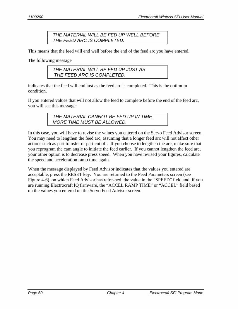
1109200 Electrocraft Wintriss SFI User Manual
Page 60 Chapter 4 Electrocraft SFI Program Mode
THE MATERIAL WILL BE FED UP WELL BEFORE THE FEED ARC IS COMPLETED.
This means that the feed will end well before the end of the feed arc you have entered.
The following message
THE MATERIAL WILL BE FED UP JUST AS THE FEED ARC IS COMPLETED.
indicates that the feed will end just as the feed arc is completed. This is the optimum condition.
If you entered values that will not allow the feed to complete before the end of the feed arc, you will see this message:
THE MATERIAL CANNOT BE FED UP IN TIME. MORE TIME MUST BE ALLOWED.
In this case, you will have to revise the values you entered on the Servo Feed Advisor screen. You may need to lengthen the feed arc, assuming that a longer feed arc will not affect other actions such as part transfer or part cut off. If you choose to lengthen the arc, make sure that you reprogram the cam angle to initiate the feed earlier. If you cannot lengthen the feed arc, your other option is to decrease press speed. When you have revised your figures, calculate the speed and acceleration ramp time again.
When the message displayed by Feed Advisor indicates that the values you entered are acceptable, press the RESET key. You are returned to the Feed Parameters screen (see Figure 4-6), on which Feed Advisor has refreshed the value in the “SPEED” field and, if you are running Electrocraft IQ firmware, the “ACCEL RAMP TIME” or “ACCEL” field based on the values you entered on the Servo Feed Advisor screen.

Electrocraft Wintriss SFI User Manual 1109200
Electrocraft SFI Program Mode Chapter 4 Page 61
USING FEED ADVISOR You can use Feed Advisor any time that you want the 1500 unit to calculate the speed,
acceleration ramp time, or acceleration for you. If you want to manually enter your own speed, acceleration ramp time, or acceleration values, select those items on the Feed Parameters screen (see Figure 4-6).
Remember to program the “Feed Initiate angle” as the “on” angle of the “Feed Advance” cam in the 1500 unit!
Loading by Tool Number
You can automatically load feed settings by tool number. To load a tool number, press RESET twice, the first time to exit from the Feed Parameters screen, the second to display the Program Menu. Press ENTER to load (or RESET to back out). You will get a message like this one, confirming that you have successfully loaded the tool:
PLEASE WAIT … LOADING TOOL 1
Loading by tool numbers is covered in Chapter 5 (Program mode) and Chapter 6 (Run mode) of the applicable 1500 series user manual.
NOTICE

Electrocraft Wintriss SFI User Manual 1109200 Electrocraft SFI Run Mode Chapter 5 Page 62
Chapter 5 Electrocraft SFI Run Mode
This chapter shows you how to use Electrocraft SFI in Run mode. You will learn how to adjust feed parameters while operating the press.
ELECTROCRAFT SFI AND SMARTPAC 1, SMARTPAC 2, AND SMARTPAC PRO You can use Electrocraft SFI with SmartPAC 2 and SmartPAC PRO as well as with the original
SmartPAC. Instructions provided in this manual that are specific to SmartPAC pertain to SmartPAC 1, SmartPAC 2, and SmartPAC PRO (refer to “SmartPAC PRO, SmartPAC 2 and Original SmartPAC,” page 3, for more information). Wiring diagrams at the back of the manual show pin connections for the different SmartPACs.
If you need additional help with your Wintriss product, refer to the applicable Wintriss user manual. Refer to the appropriate Electrocraft servofeed manual for more information about your Electrocraft servofeed.
READ YOUR ELECTROCRAFT SERVOFEED MANUAL BEFORE MAKING ANY SETTINGS! Make sure you have read the appropriate Electrocraft servofeed manual and understand how
your servofeed works before making any settings.
Using Electrocraft SFI Run Mode in SmartPAC
About Tool Numbers
A tool number consists of all of the settings (including the servofeed settings) that you make for one job. You can save servofeed information for up to 200 tools and then recall the settings for each job whenever you need to.
SELECT = HIGHLIGHT + ENTER When you are instructed in this manual to “select” a menu item, press the Up (▲) or Down (▼)
cursor key to highlight the item, then press the ENTER key. See Chapter 3 in the SmartPAC user manual for more information.
NOTICE
NOTICE
NOTICE

Electrocraft Wintriss SFI User Manual 1109200
Electrocraft SFI Run Mode Chapter 5 Page 63
Run Menu
While you are running the press, SmartPAC will operate the Electrocraft servofeed based upon the settings you have made in Program mode. In some cases, you can make minor adjustments to the currently loaded tool number.
To use Run mode, turn the Program/Run key to “RUN.” The Run Menu, shown in Figure 5-1, will display (the order of items may vary depending on installed options).
Figure 5-1. SmartPAC Run Menu with “FEED CONTROL” Selected
To adjust feed settings, select “FEED CONTROL.” If you are running Electrocraft IQ firmware and you have made Initialization settings for an Electrocraft IQ controller, the Feed Control screen, shown in Figure 5-2, displays.
Figure 5-2. SmartPAC Feed Control Screen with “FEED LENGTH” Selected

1109200 Electrocraft Wintriss SFI User Manual
Page 64 Chapter 5 Electrocraft SFI Run Mode
If you are running Electrocraft IQ firmware and you have made Initialization settings for an Electrocraft BRU controller with an Exor terminal, the Feed Control screen will also include an Acceleration field and display both Speed and Acceleration as a percentage of the maximum speed and acceleration you established in Initialization.
If you are running Electrocraft BRU firmware, the Speed field is displayed as a percentage of maximum speed.
This screen allows you to make minor adjustments to feed length, speed, or acceleration. To do so, you select an item, then use the Up (▲) or Down (▼) cursor key to increment or decrement the value for that item. Note that the Feed Length value changes by .001 inch (1/1000) each time you press the Up (▲) or Down (▼) key.
Changes you make to settings on this screen are sent directly to the servofeed and saved immediately to the currently loaded tool. Be sure to make a note of feed setup changes on your feed setup sheet for future reference.
When you are done, press the RESET key to exit from this display.
Using Electrocraft SFI Run Mode in a 1500 Series Control
About Tool Numbers
A tool number consists of all of the settings (including the servofeed settings) that you make for one job. You can save servofeed information for up to 200 tools and then recall the settings for each job whenever you need to.
Run Menu
While you are running the press, the 1500 control will operate the servofeed based on the settings you made in Program mode. In some cases, you can make minor adjustments to the currently loaded tool number.
To use Run mode, turn the Program/Run key to “RUN.” If you are running Electrocraft IQ firmware, the Run Menu shown in Figure 5-3 (next page) will display. If you are running Electrocraft BRU firmware, a similar menu will display with the ADJUST FEED item replaced by ADJUST FEED/STATUS.

Electrocraft Wintriss SFI User Manual 1109200
Electrocraft SFI Run Mode Chapter 5 Page 65
Figure 5-3. 1500 Series Run Menu with “ADJUST FEED” Selected
To adjust feed settings, select “ADJUST FEED” or “ADJUST FEED/STATUS.” If you are running Electrocraft IQ firmware, the Adjust Feed screen shown in Figure 5-4 displays. If you are running Electrocraft BRU firmware, the Speed value is displayed as a percentage of maximum speed rather than in inches per second.
Figure 5-4. 1500 Series Adjust Feed Screen with “FEED LENGTH” Selected
This screen allows you to make minor adjustments to feed length and run speed. To do so, you select an item, then use the Up (▲) or Down (▼) cursor key to increment or decrement the value for that item. Note that the Feed Length value changes by .001 inch (1/1000) each time you press the Up (▲) or Down (▼) key.
Changes you make to settings on this screen are sent directly to the servofeed and saved immediately to the currently loaded tool. Be sure to make a note of feed setup changes on your feed setup sheet for future reference.
When you are done, press the RESET key to exit from the Adjust Feed screen.

Electrocraft Wintriss SFI User Manual 1109200 Electrocraft SFI Troubleshooting Chapter 6 Page 66
Chapter 6 Electrocraft SFI Troubleshooting
This chapter documents troubleshooting messages that are generated because of problems with the interface between the Electrocraft servofeed and the Wintriss control and shows you how to respond to them. It does not cover other Wintriss- or Electrocraft-generated fault messages. Consult the appropriate Wintriss control or Electrocraft servofeed user manual for these faults.
This chapter covers the communications fault message on SmartPAC and 1500 series controls.
ELECTROCRAFT SFI AND SMARTPAC 1, SMARTPAC 2, AND SMARTPAC PRO You can use Electrocraft SFI with SmartPAC 2 and SmartPAC PRO as well as with the original
SmartPAC. Instructions provided in this manual that are specific to SmartPAC pertain to SmartPAC 1, SmartPAC 2, and SmartPAC PRO (refer to “SmartPAC PRO, SmartPAC 2 and Original SmartPAC,” page 3, for more information). Wiring diagrams at the back of the manual show pin connections for the different SmartPACs.
Troubleshooting in SmartPAC Whenever SmartPAC and the Electrocraft feed control unit are not communicating with one another, the message shown in Figure 6-1 will appear on the LCD.
Figure 6-1. SmartPAC Communications Fault Message
NOTICE

Electrocraft Wintriss SFI User Manual 1109200
Electrocraft SFI Troubleshooting Page 67
When you get this message, check that all wiring connections are intact. Refer to Chapter 2 to verify correct installation if necessary. Also refer to the section “Viewing Communications,” page 40 to review the procedure for displaying Receive and Transmit data sent between SmartPAC and the Electrocraft feed controller. Contact Wintriss Tech. Support for help in interpreting the screen and conducting loopback tests.
Once communications are restored, you will no longer see this fault message.
Troubleshooting in a 1500 Series Control Whenever either ProCam 1500 or DiPro 1500 and the Electrocraft feed control unit are not communicating with one another, the message shown in Figure 6-2 will appear on the LCD.
Figure 6-2. 1500 Series Communications Fault Message
When you get this message, check that all wiring connections are intact. Refer to Chapter 2 if necessary. Once communications are restored, you will no longer see this fault message.

Electrocraft Wintriss SFI User Manual 1109200 Index Page 68
Index
—1—
1500 series controls initializing feed control parameters, 43 installing firmware, 27 loading feed settings by tool number, 61 setting feed control parameters in
Program mode, 57 using Feed Advisor, 58 wiring to an Electrocraft servofeed, 31
—A—
Adjust Feed locking in DiPro 1500, 46 locking in ProCam 1500, 45 locking in SmartPAC, 39
advance constant. See auto advance constant (DiPro 1500)
auto advance constant (DiPro 1500) calculating, 47 setting, 48
—C—
communications troubleshooting in 1500 series controls,
67 troubleshooting in SmartPAC, 67 verifying in SmartPAC, 40
—D—
DiPro 1500 calculating the auto advance constant, 47 locking Adjust Feed, 46 setting slow RPM, 49 setting the auto advance constant, 48
—E—
Electrocraft BRU servofeed adjusting settings in Run mode (1500
series control), 65
adjusting settings in Run mode (SmartPAC), 64
entering Program settings in a 1500 series control, 57
entering Program settings in SmartPAC, 52
installing firmware in a 1500 series control, 27
installing firmware in SmartPAC, 20 setting Initialization parameters in a
1500 series control, 44 setting Initialization parameters in
SmartPAC, 38 wiring to a 1500 series control, 31 wiring to SmartPAC, 23
Electrocraft BRU servofeed with Exor terminal adjusting settings in Run mode (1500
series control), 65 adjusting settings in Run mode
(SmartPAC), 64 entering Program settings in a 1500
series control, 57 entering Program settings in SmartPAC,
52 installing firmware in a 1500 series
control, 27 installing firmware in SmartPAC, 20 setting Initialization parameters in a
1500 series control, 43 setting Initialization parameters in
SmartPAC, 37 wiring to a 1500 series control, 31 wiring to SmartPAC, 23
Electrocraft IQ servofeed adjusting settings in Run mode (1500
series control), 65 adjusting settings in Run mode
(SmartPAC), 63 entering Program settings in a 1500
series control, 57

1125100 WPC 1000 Wintriss Clutch/Brake Control User Manual
Index Page 69
entering Program settings in SmartPAC, 52
installing firmware in a 1500 series control, 27
installing firmware in SmartPAC, 20 setting Initialization parameters in a
1500 series control, 43 setting Initialization parameters in
SmartPAC, 35 wiring to a 1500 series control, 31 wiring to SmartPAC, 23
Electrocraft parameters. See feed control parameters
EPROM. See firmware, SFI
—F—
Feed Advisor using in 1500 series controls, 58 using in SmartPAC, 53
feed control parameters initializaing in a 1500 series control, 43 initializing in SmartPAC, 36 loading by tool number (1500 series
controls), 61 loading by tool number (SmartPAC), 55 making adjustments in Run mode (1500
series controls), 64 making adjustments in Run mode
(SmartPAC), 63 setting in Program mode (1500 series
controls), 57 setting in Program mode (SmartPAC),
52 feed settings. See feed control parameters firmware, SFI
installing in a 1500 series control, 27 installing in SmartPAC, 20
—L—
loopback test, performing, 41, 67
—P—
pilot release, calculating auto advance constant for, 47
ProCam 1500, locking Adjust Feed, 45
—S—
Slow RPM, setting in DiPro 1500, 49 SmartPAC
initializing feed control parameters, 35 installing firmware, 20 loading feed settings by tool number, 55 locking Adjust Feed, 39 setting feed control parameters in
Program mode, 52 using Feed Advisor, 53 verifying communications, 40 wiring to an Electrocraft servofeed, 23
SmartPAC 2, SmartPAC PRO, using Electrocraft SFI with, 15
—T—
tool number loading feed control parameters by
(1500 series controls), 61 loading feed control parameters by
(SmartPAC), 55
—W—
wiring connections making on a 1500 series control, 31 making on a SmartPAC, 23


