electromagnetic fault injection : how
TRANSCRIPT

Electromagnetic Fault Injection : how faults occur ?
Fault Diagnosis and Tolerance in Cryptography 2019
24/08/19

2Introduction
• Context : Attack by Fault injection : Glitch attack, Laser attack, Electromagnetic
Fault injection (EMFI).
EMFI Fault model : Timing Fault (2012) by A.Dehbaoui ; Sampling
fault (2016) S.Ordas.
• Objectives : Modelling : impact of an EMFI on IC supply voltage
SPICE simulation : impact of an EMFI on IC operation
Experimental validation
LAS
ER
EM
probeVDD
Glitch

Modelling: Impact of an EMFI on IC supply voltage

EMFI induces parasitic currents mostly in the power and ground networks.
Probe IC
• EM Induction: hypothesis ?
• EM induction induces currents variation on closed loops.
• Metal wires from the power/ground networks form many loops !
• Interconnect logic wires don’t form loops.
Modelling: Impact of an EMFI on IC4
EM
probe

GNDVDD
Modelling: Impact of an EMFI on IC• Impact of EMFI on supply voltage.
GND
VDD PADSupply Grid VDD
GND
VDD
PAD
R
R
L
L
Cde cap
Supply grid GND
Coupling Probe/Vdd grid
Coupling Probe/Gnd grid
Vdd_Left Vdd_Right
Gnd_Left Gnd_Right
VDDGND
5

GND
VDD PADSupply Grid VDD
GND
VDD
PAD
R
R
L
L
Cde cap
Supply grid GND
Coupling Probe/Vdd grid
Coupling Probe/Gnd grid
Vdd_Left Vdd_Right
Gnd_Left Gnd_Right
Modelling: Impact of an EMFI on IC6
• Impact of EMFI on supply voltage.
Swing is negative for few ns !

Spice Simulation : impact of EMFI on IC operation
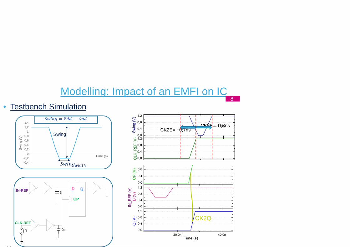
CK2E= +0,7ns
-0,4-0,2
00,20,40,60,8
11,21,4
Sw
ing
(V) Swing
Modelling: Impact of an EMFI on IC8
• Testbench Simulation
OUT
CK2QQ
QSET
CLR
DCL
CCLKCLK
CP
CLK-REF
CK2E= -0,8nsCK2E = 0ns
D QIN-REF
Time (s)

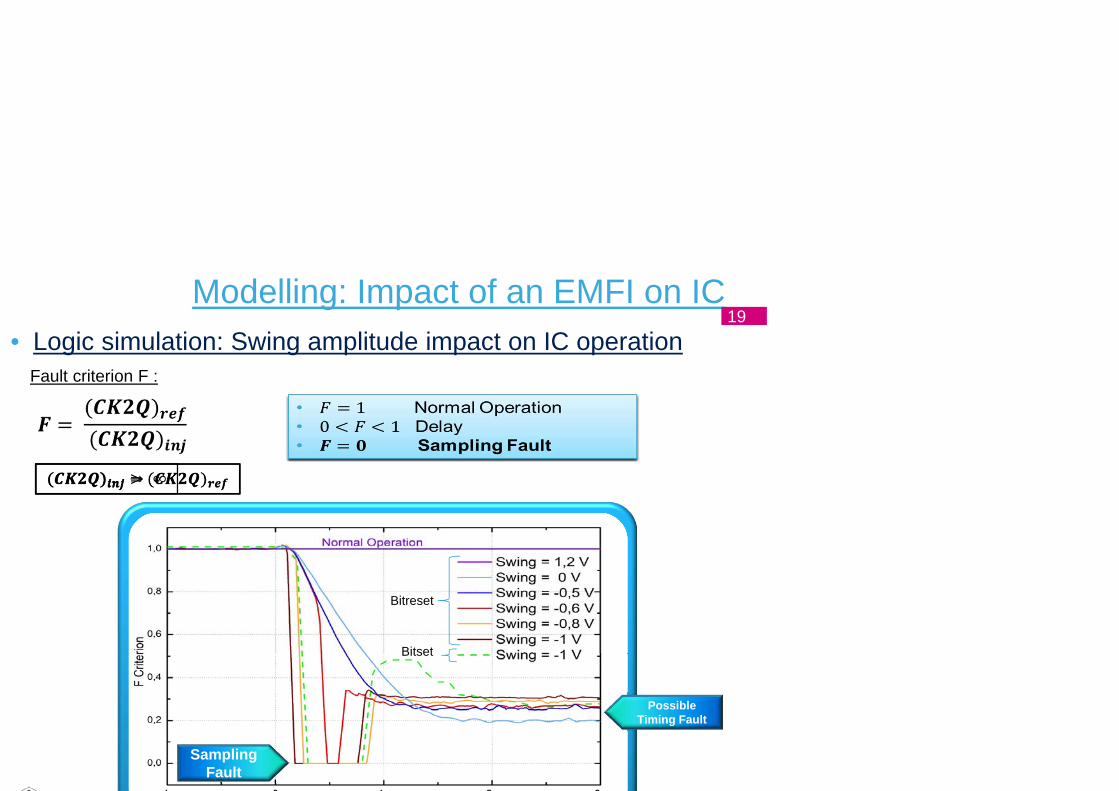
• Logic simulation: Swing amplitude impact on IC operation
Modelling: Impact of an EMFI on IC9
Fault criterion F :
Possible Timing Fault
Sampling Fault

• Sampling Fault explanation
D
CP
NO FAULT
Normal Operation
Modelling: Impact of an EMFI on IC10
Q = ‘1’

• Sampling Fault explanation
TIMING FAULT
D
CP
Modelling: Impact of an EMFI on IC11
Q = ‘0’

• Sampling Fault explanation
SAMPLING FAULT
D
Modelling: Impact of an EMFI on IC12
Q = ‘0’ CP

Experimental Validation

EMFI experimental validation14
•
~ 34ns
30 MHz, T=33,3ns
EM Pulse
0 % probability to induce sampling fault ~100 % probability to
induce sampling fault
Pulse Delay (ns)0 10 20
sweep
~ 34ns
7.1ns
~ 13.5 ns
30 MHz, T=33,3ns
50 MHz, T=20ns
70 MHz, T=14ns
~ 21ns
6.3ns
6.8ns

EMFI experimental validation15
•
Sampling Fault windows width
1.9ns9.2ns7.1ns

EMFI experimental validation16
• Effect of PW variations• Determine the evolution of the Sampling Fault Window width in function of PW variations.
• The Pulse Width does not affect much the sampling fault window.

Conclusion 17
• Conclusion Modelling simulations show that EMFI induces a voltage bounces or drops on power
networks Vdd and GND. That could induce a Swing drop.
Sampling Fault occurs when EM Field is applied during IC operation around rising CLK
edge. In simulation and experimentally.
• Perspective More accurate coupling model.
Experimental validation and parallel on one register only.

Thank you
Electromagnetic Fault Injection : how faults occur ?
• Logic simulation: Swing amplitude impact on IC operation
Modelling: Impact of an EMFI on IC19
Fault criterion F :
Possible Timing Fault
Sampling Fault
Bitreset
Bitset

• Sampling Fault explanation
SAMPLING FAULT
D
CP
Modelling : Impact of an EMFI on IC20
ZOOM

• Sampling Fault explanation
D Q
CPI
CPN
CPI
CPN
CPI
CPN CPI
CPN
Master
Slave
D Q
CPI
CPN
CPI
CPN
CPI CPN
CLK = 0
CLK = 1
V1
V1
V1 is disrupted during the D recovery
V1 depends on D when CLK = 0
If CLK edge occurs during V1 alteration : wrong value is sampled and stored in Master loop.
Sampling Fault !
Modelling : Impact of an EMFI on IC21