electromagnetic induction - pearson global...
TRANSCRIPT
661
How might electrical stimulation of the brain help treat certain diseases?
How does a microphone work?
How does a vending machine sort coins?
18Electromagnetic Induction
Be sure you know how to:
■ Find the direction of the u
B field produced by an electric current (Section 17.2).
■ Find the direction of the magnetic force exerted on moving electric charges (Sections 17.3 and 17.4).
■ Explain how an electric field produces a current in a wire and how that current relates to the re-sistance of the wire (Sections 16.1 and 16.4).
Because human cells, including nerve cells, contain ions that can move, they are electrically conductive. For some time, scientists have believed that the electrical nature of the
brain could be used to help treat certain diseases. However, the skull is a
fairly good electrical insulator. Until recently, the only options for electri-
cal stimulation of the brain were either to apply a very high potential
difference across points on the skull or to surgically implant electrodes
into the brain. Now there is a promising new way to study and alter the
electric activity of the brain noninvasively. This technology, called tran-
scranial magnetic stimulation (TMS), may help treat mood disorders,
Parkinson’s disease, and Huntington’s disease. TMS studies have also
M18_VANH5357_01_SE_C18.indd 661 19/07/13 10:19 AM
662 Chapter 18 electromagnetic Induction
helped medical researchers understand the processes involved in neural
repair, learning, and memory.
TMS treatment is fairly simple: a clinician places a small coil of wire
on or near the patient’s scalp. The changing current through this coil
produces an abrupt electric current in the brain directly under the coil,
even though there is no electrical connection between the outside coil
and the brain. How is this possible?
In the last chapter, we learned that an electric current through a wire produces a magnetic field. Could the reverse happen? Could a magnetic field produce a current? It took scientists many years to answer this ques-tion. In this chapter, we will investigate the conditions under which this can happen.
18.1 Inducing an electric currentIn the chapter on circuits (Chapter 16), we learned that an electric current re-sults when a battery or some other device produces an electric field in a wire. The field in turn exerts an electric force on the free electrons in the wire con-nected to the battery. As a result, the electrons move in a coordinated manner around the circuit—an electric current.
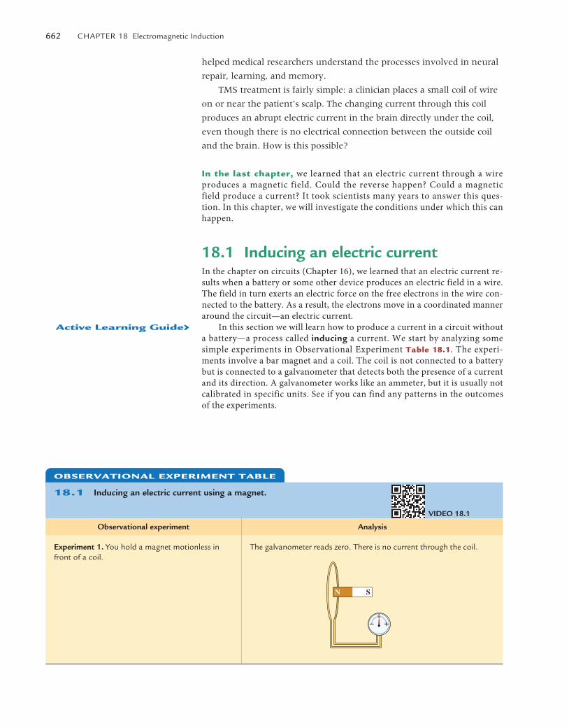
In this section we will learn how to produce a current in a circuit without a battery—a process called inducing a current. We start by analyzing some simple experiments in Observational Experiment Table 18.1. The experi-ments involve a bar magnet and a coil. The coil is not connected to a battery but is connected to a galvanometer that detects both the presence of a current and its direction. A galvanometer works like an ammeter, but it is usually not calibrated in specific units. See if you can find any patterns in the outcomes of the experiments.
ObservaTIOnal experImenT Table
18.1 Inducing an electric current using a magnet.
Observational experiment Analysis
Experiment 1. You hold a magnet motionless in front of a coil.
the galvanometer reads zero. there is no current through the coil.
N S
VIdEO 18.1
active learning Guide›
M18_VANH5357_01_SE_C18.indd 662 19/07/13 10:19 AM
18.1 Inducing an electric current 663
In Table 18.1 there was no battery, yet the galvanometer registered an electric current through a coil. For the current to exist, there must be some source of emf. What produced the emf in the experiments in Table 18.1?
Recall from our study of magnetism (in Chapter 17) that a magnetic field can exert a force on moving electrically charged particles. The force exists only if the magnetic field or a component of the field is perpendicular to the velocity of the electrically charged particles. Let’s consider again Experiment 2 in Table 18.1 in which the coil moves toward the magnet; for simplicity, we use a square loop made of conducting wire (Figure 18.1). Inside the wire there are posi-tively charged ions that make up the lattice of the metal (and cannot leave their
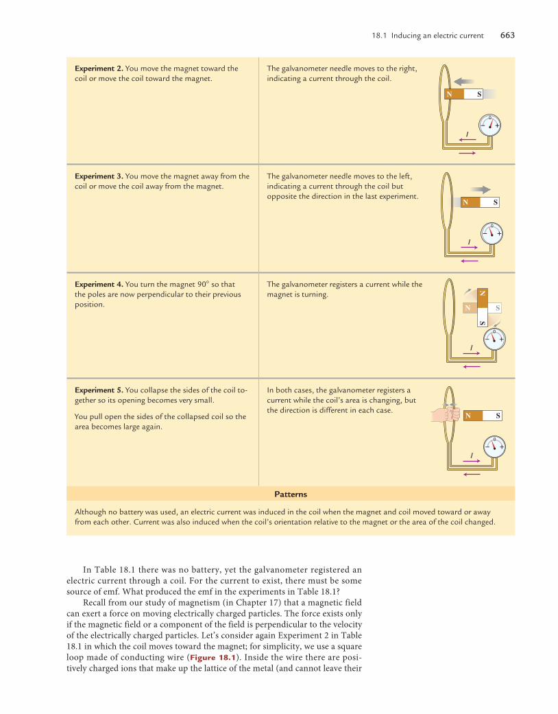
Experiment 2. You move the magnet toward the coil or move the coil toward the magnet.
the galvanometer needle moves to the right, indicating a current through the coil.
Experiment 3. You move the magnet away from the coil or move the coil away from the magnet.
the galvanometer needle moves to the left, indicating a current through the coil but opposite the direction in the last experiment.
Experiment 4. You turn the magnet 90� so that the poles are now perpendicular to their previous position.
the galvanometer registers a current while the magnet is turning.
Experiment 5. You collapse the sides of the coil to-gether so its opening becomes very small.
You pull open the sides of the collapsed coil so the area becomes large again.
In both cases, the galvanometer registers a current while the coil’s area is changing, but the direction is different in each case.
Patterns
although no battery was used, an electric current was induced in the coil when the magnet and coil moved toward or away from each other. Current was also induced when the coil’s orientation relative to the magnet or the area of the coil changed.
N S
I
I
N S
I
N S
NS
I
N S
M18_VANH5357_01_SE_C18.indd 663 19/07/13 10:19 AM
664 Chapter 18 electromagnetic Induction
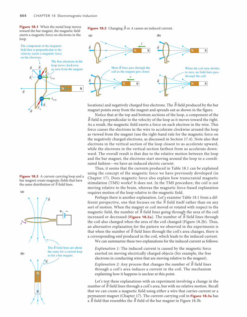
locations) and negatively charged free electrons. The u
B field produced by the bar magnet points away from the magnet and spreads out as shown in the figure.
Notice that at the top and bottom sections of the loop, a component of the u
B field is perpendicular to the velocity of the loop as it moves toward the right. As a result, the magnetic field exerts a force on each electron in the wire. This force causes the electrons in the wire to accelerate clockwise around the loop as viewed from the magnet (use the right-hand rule for the magnetic force on the negatively charged electrons, as discussed in Section 17.4). Note also that electrons in the vertical section of the loop closest to us accelerate upward, while the electrons in the vertical section farthest from us accelerate down-ward. The overall result is that due to the relative motion between the loop and the bar magnet, the electrons start moving around the loop in a coordi-nated fashion—we have an induced electric current.
Thus, it seems that the currents produced in Table 18.1 can be explained using the concept of the magnetic force we have previously developed (in Chapter 17). Does magnetic force also explain how transcranial magnetic stimulation (TMS) works? It does not. In the TMS procedure, the coil is not moving relative to the brain, whereas the magnetic force-based explanation requires motion of the loop relative to the magnetic field.
Perhaps there is another explanation. Let’s examine Table 18.1 from a dif-ferent perspective, one that focuses on the
u
B field itself rather than on any sort of motion. When the magnet or coil moved or rotated with respect to the magnetic field, the number of
u
B field lines going through the area of the coil increased or decreased (Figure 18.2a). The number of
u
B field lines through the coil also changed when the area of the coil changed (Figure 18.2b). Thus, an alternative explanation for the pattern we observed in the experiments is that when the number of
u
B field lines through the coil’s area changes, there is a corresponding emf produced in the coil, which leads to the induced current.
We can summarize these two explanations for the induced current as follows:
Explanation 1: The induced current is caused by the magnetic force exerted on moving electrically charged objects (for example, the free electrons in conducting wires that are moving relative to the magnet).Explanation 2: Any process that changes the number of
u
B field lines through a coil’s area induces a current in the coil. The mechanism explaining how it happens is unclear at this point.
Let’s test these explanations with an experiment involving a change in the number of
u
B field lines through a coil’s area, but with no relative motion. Recall that we can create a magnetic field using either a wire that carries current or a permanent magnet (Chapter 17). The current-carrying coil in Figure 18.3a has a
u
B field that resembles the u
B field of the bar magnet in Figure 18.3b.
(a)
When the coil area shrinksto zero, no field lines passthrough the coil.
More B lines pass through thecoil as the magnet gets closer.
r
rB
rB
rv
N S
rv
N S
(b)
rBN S
rBN S
Figure 18.2 Changing u
B or A causes an induced current.
N S
The free electrons in theloop move clockwiseas seen from the magnet.
The component of the magneticfield that is perpendicular to thevelocity exerts a magnetic forceon the electrons.
rB
rB�
rB}
rFm
rvloop
rB
rB
rB�r
Fm
rvloop
Figure 18.1 When the metal loop moves toward the bar magnet, the magnetic field exerts a magnetic force on electrons in the loop.
(b)
(a)
rB
rB
The B field lines are about the same for a current loopas for a bar magnet.
r
I
N
S
Figure 18.3 A current-carrying loop and a bar magnet create magnetic fields that have the same distribution of
u
B field lines.
M18_VANH5357_01_SE_C18.indd 664 19/07/13 10:19 AM
18.1 Inducing an electric current 665
Testing experiment
Will a current be induced in coil 2?
Prediction based on Explanation 1:
Induced current is due to magnetic force
exerted on moving charged particles.
Will a current be induced in coil 2?
Prediction based on Explanation 2:
Induced current is due to changing number of
u
B field lines through coil.
Outcome
Experiment 1. the switch in the circuit for coil 1 is open. there is no current in coil 1. Is there any current in coil 2?
there is no current in coil 1, thus there is no magnetic field at coil 2. Neither coil is moving. No current will be induced in coil 2.
there is no current in coil 1; therefore, there is no change in the number of
u
B field lines through coil 2’s area. No current will be induced in coil 2.
Coil 2
Coil 1
the galvanometer registers no current in coil 2.
Experiment 2. You close the switch in the circuit for coil 1. While the switch is being closed, the current in coil 1 increases rapidly from zero to a steady final value. Is there any current in coil 2 while the switch is being closed?
Neither coil is moving, thus no current will be induced in coil 2.
the increasing current in coil 1 produces an increasing
u
B field. this changes the number of u
B field lines through coil 2’s area. a brief current should be induced in coil 2.
Coil 2
Coil 1
Iin
I1 increasing
rB1 increasing
Just as the switch closes, the galvanom-eter needle briefly moves to the left and then returns to vertical, indicating a brief induced current in coil 2.
Experiment 3. You keep the switch in the circuit for coil 1 closed. the current in coil 1 has a steady value. Is there current in coil 2?
Neither coil is moving. thus no current will be induced in coil 2.
there is a steady current in coil 1, which results in a steady
u
B field. thus, the number of
u
B field lines through coil 2’s area is not changing. therefore, no current will be induced in coil 2.
Coil 2
Coil 1
I1
rB1 steady
the galvanometer registers no current in coil 2.
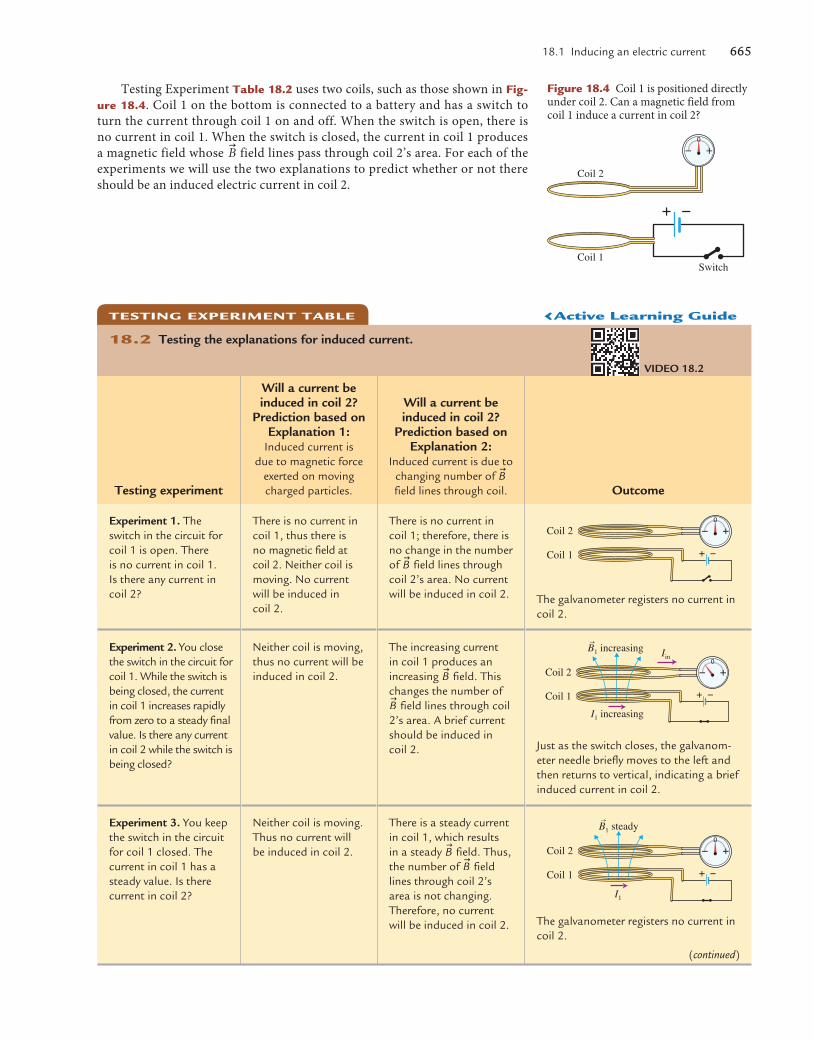
Testing Experiment Table 18.2 uses two coils, such as those shown in Fig-ure 18.4. Coil 1 on the bottom is connected to a battery and has a switch to turn the current through coil 1 on and off. When the switch is open, there is no current in coil 1. When the switch is closed, the current in coil 1 produces a magnetic field whose
u
B field lines pass through coil 2’s area. For each of the experiments we will use the two explanations to predict whether or not there should be an induced electric current in coil 2.
Coil 2
Coil 1Switch
Figure 18.4 Coil 1 is positioned directly under coil 2. Can a magnetic field from coil 1 induce a current in coil 2?
TesTInG experImenT Table
18.2 Testing the explanations for induced current.
VIdEO 18.2
(continued)
‹active learning Guide
M18_VANH5357_01_SE_C18.indd 665 19/07/13 10:19 AM
666 Chapter 18 electromagnetic Induction
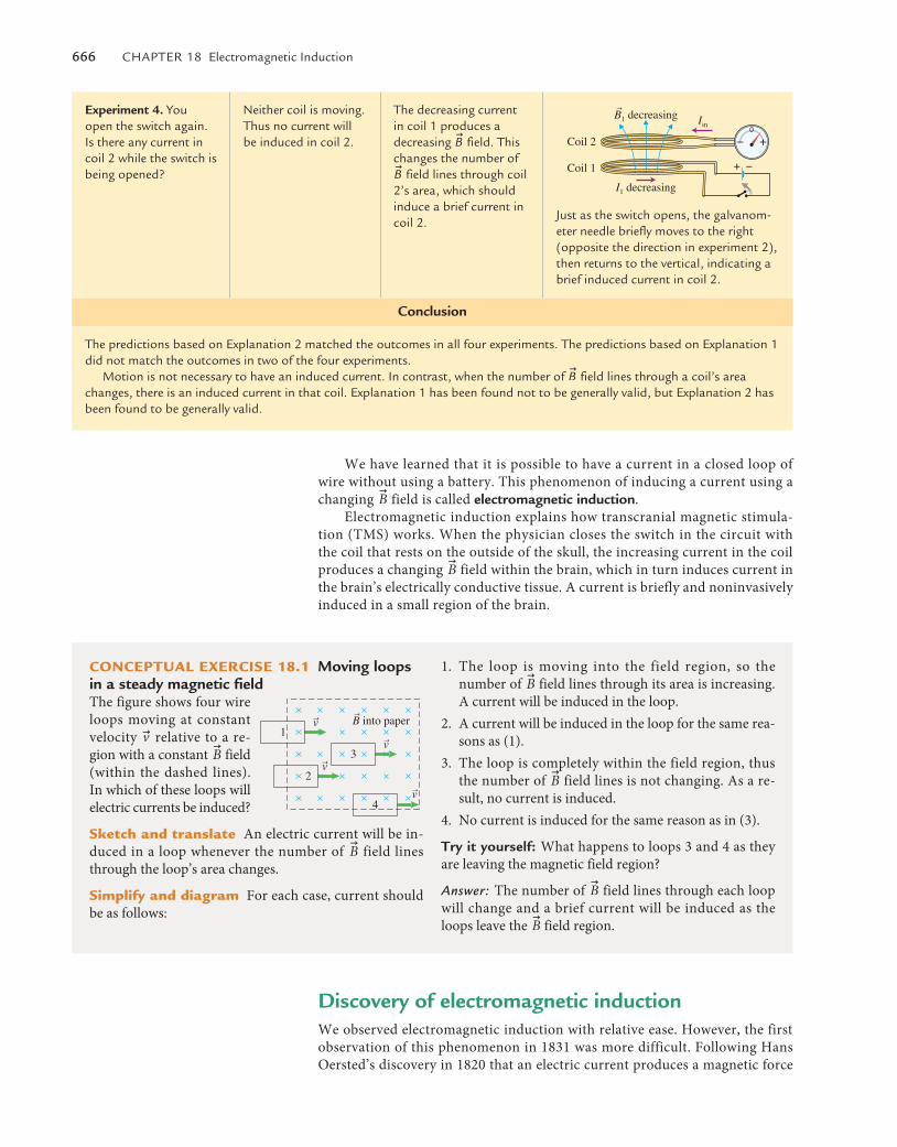
Experiment 4. You open the switch again. Is there any current in coil 2 while the switch is being opened?
Neither coil is moving. thus no current will be induced in coil 2.
the decreasing current in coil 1 produces a decreasing
u
B field. this changes the number of u
B field lines through coil 2’s area, which should induce a brief current in coil 2.
Coil 2
Coil 1
Iin
I1 decreasing
rB1 decreasing
Just as the switch opens, the galvanom-eter needle briefly moves to the right (opposite the direction in experiment 2), then returns to the vertical, indicating a brief induced current in coil 2.
Conclusion
the predictions based on explanation 2 matched the outcomes in all four experiments. the predictions based on explanation 1 did not match the outcomes in two of the four experiments.
Motion is not necessary to have an induced current. In contrast, when the number of u
B field lines through a coil’s area changes, there is an induced current in that coil. explanation 1 has been found not to be generally valid, but explanation 2 has been found to be generally valid.
We have learned that it is possible to have a current in a closed loop of wire without using a battery. This phenomenon of inducing a current using a changing
u
B field is called electromagnetic induction.Electromagnetic induction explains how transcranial magnetic stimula-
tion (TMS) works. When the physician closes the switch in the circuit with the coil that rests on the outside of the skull, the increasing current in the coil produces a changing
u
B field within the brain, which in turn induces current in the brain’s electrically conductive tissue. A current is briefly and noninvasively induced in a small region of the brain.
COnCepTual exerCIse 18.1 Moving loops in a steady magnetic fieldThe figure shows four wire loops moving at constant velocity u
v relative to a re-gion with a constant
u
B field (within the dashed lines). In which of these loops will electric currents be induced?
sketch and translate An electric current will be in-duced in a loop whenever the number of
u
B field lines through the loop’s area changes.
simplify and diagram For each case, current should be as follows:
1. The loop is moving into the field region, so the number of
u
B field lines through its area is increasing. A current will be induced in the loop.
2. A current will be induced in the loop for the same rea-sons as (1).
3. The loop is completely within the field region, thus the number of
u
B field lines is not changing. As a re-sult, no current is induced.
4. No current is induced for the same reason as in (3).
Try it yourself: What happens to loops 3 and 4 as they are leaving the magnetic field region?
Answer: The number of u
B field lines through each loop will change and a brief current will be induced as the loops leave the
u
B field region.
1
3
2
4
rB into paperrvrv
rv
rv
discovery of electromagnetic inductionWe observed electromagnetic induction with relative ease. However, the first observation of this phenomenon in 1831 was more difficult. Following Hans Oersted’s discovery in 1820 that an electric current produces a magnetic force
M18_VANH5357_01_SE_C18.indd 666 19/07/13 10:19 AM
18.2 Magnetic flux 667
on a compass needle, scientists wondered if the reverse might occur—could an object with magnetic properties produce an electric current? In 1821, British ex-perimentalist Michael Faraday began investigating the possibility. Two difficul-ties lay before him—one conceptual and one technical. The conceptual difficulty was that although a steady current always produces a magnetic field, a steady magnetic field does not always produce an electric current. The technical diffi-culty was that the galvanometers of the time could not detect the weak currents induced in a single loop. Coils of wire (multiple loops of wire) were needed to amplify the magnetic effect. However, individual wires cannot be in contact with each other; they must be insulated from touching each other. At the time, no pro-cess existed for producing insulated wires; thus there was no way to make coils.
The technical problem was solved when American physicist Joseph Henry devised and published a method for insulating wires by wrapping them in silk. Henry was the first to observe a current being induced in a coil. He did not immediately publish his discovery, however. In 1831, upon learning about Henry’s work, Faraday used Henry’s insulation method to induce current in coils in his laboratory. Since then, scientists and engineers have devised many practical devices based on electromagnetic induction, such as electric genera-tors, magnetic credit card readers, the transformers needed for modern elec-tric power grids, and the pick-up coils for string and percussion instruments.
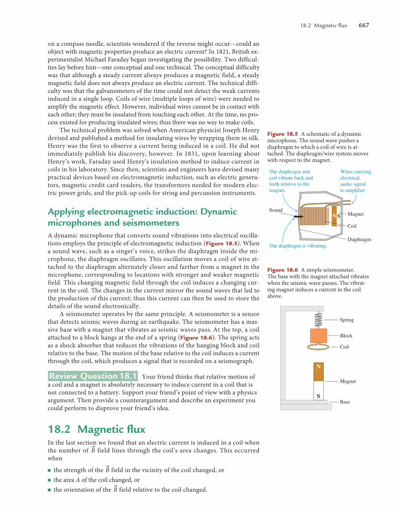
Applying electromagnetic induction: dynamic microphones and seismometersA dynamic microphone that converts sound vibrations into electrical oscilla-tions employs the principle of electromagnetic induction (Figure 18.5). When a sound wave, such as a singer’s voice, strikes the diaphragm inside the mi-crophone, the diaphragm oscillates. This oscillation moves a coil of wire at-tached to the diaphragm alternately closer and farther from a magnet in the microphone, corresponding to locations with stronger and weaker magnetic field. This changing magnetic field through the coil induces a changing cur-rent in the coil. The changes in the current mirror the sound waves that led to the production of this current; thus this current can then be used to store the details of the sound electronically.
A seismometer operates by the same principle. A seismometer is a sensor that detects seismic waves during an earthquake. The seismometer has a mas-sive base with a magnet that vibrates as seismic waves pass. At the top, a coil attached to a block hangs at the end of a spring (Figure 18.6). The spring acts as a shock absorber that reduces the vibrations of the hanging block and coil relative to the base. The motion of the base relative to the coil induces a current through the coil, which produces a signal that is recorded on a seismograph.
Review Question 18.1 Your friend thinks that relative motion of a coil and a magnet is absolutely necessary to induce current in a coil that is not connected to a battery. Support your friend’s point of view with a physics argument. Then provide a counterargument and describe an experiment you could perform to disprove your friend’s idea.
18.2 Magnetic fluxIn the last section we found that an electric current is induced in a coil when the number of
u
B field lines through the coil’s area changes. This occurred when
■ the strength of the u
B field in the vicinity of the coil changed, or■ the area A of the coil changed, or■ the orientation of the
u
B field relative to the coil changed.
Sound
Wires carryingelectricalaudio signalto amplifier
Magnet
Coil
Diaphragm
The diaphragm andcoil vibrate back andforth relative to themagnet.
The diaphragm is vibrating.
N S
Figure 18.5 A schematic of a dynamic microphone. The sound wave pushes a diaphragm to which a coil of wire is at-tached. The diaphragm/wire system moves with respect to the magnet.
Spring
Magnet
Block
Coil
Base
N
S
Figure 18.6 A simple seismometer. The base with the magnet attached vibrates when the seismic wave passes. The vibrat-ing magnet induces a current in the coil above.
M18_VANH5357_01_SE_C18.indd 667 19/07/13 10:19 AM
668 Chapter 18 electromagnetic Induction
In this section we will construct a physical quantity for the number of u
B field lines through a coil’s area. Based on the analysis in the last section, changes in that quantity should cause an induced electric current in the coil. Physicists call this physical quantity magnetic flux �.
We have already defined the magnetic flux qualitatively as the number of u
B field lines passing through a particular two-dimensional area A. The greater the magnitude of the
u
B field passing through the area, the greater the number of field lines through the area. Additionally, if the area itself is larger, the num-ber of field lines through the area is greater. If we double one or the other, the number of lines through the area should double. This suggests that the mag-netic flux is proportional to the magnitude of the
u
B field passing through the area and to the size of the area itself. Mathematically,
� � BA
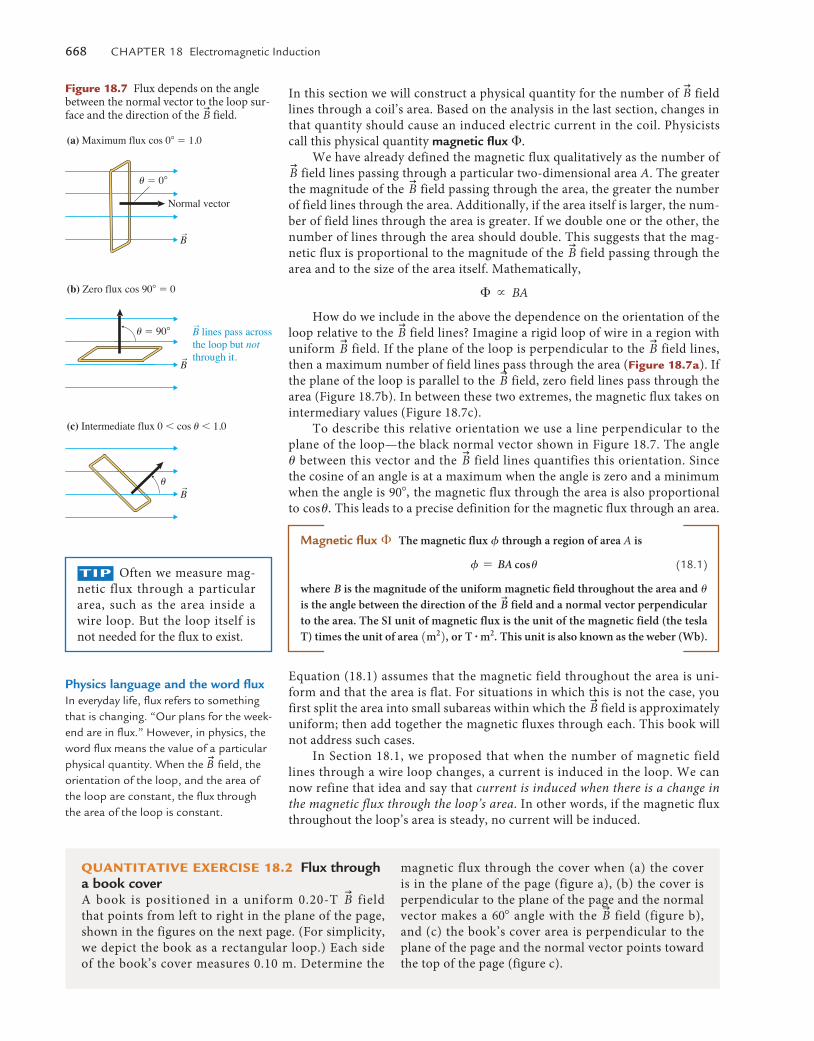
How do we include in the above the dependence on the orientation of the loop relative to the
u
B field lines? Imagine a rigid loop of wire in a region with uniform
u
B field. If the plane of the loop is perpendicular to the u
B field lines, then a maximum number of field lines pass through the area (Figure 18.7a). If the plane of the loop is parallel to the
u
B field, zero field lines pass through the area (Figure 18.7b). In between these two extremes, the magnetic flux takes on intermediary values (Figure 18.7c).
To describe this relative orientation we use a line perpendicular to the plane of the loop—the black normal vector shown in Figure 18.7. The angle u between this vector and the
u
B field lines quantifies this orientation. Since the cosine of an angle is at a maximum when the angle is zero and a minimum when the angle is 90�, the magnetic flux through the area is also proportional to cos u. This leads to a precise definition for the magnetic flux through an area.
Magnetic flux � The magnetic flux f through a region of area A is
f = BA cos u (18.1)
where B is the magnitude of the uniform magnetic field throughout the area and u is the angle between the direction of the
u
B field and a normal vector perpendicular to the area. The SI unit of magnetic flux is the unit of the magnetic field (the tesla T) times the unit of area 1m22, or T # m2. This unit is also known as the weber (Wb).
Equation (18.1) assumes that the magnetic field throughout the area is uni-form and that the area is flat. For situations in which this is not the case, you first split the area into small subareas within which the
u
B field is approximately uniform; then add together the magnetic fluxes through each. This book will not address such cases.
In Section 18.1, we proposed that when the number of magnetic field lines through a wire loop changes, a current is induced in the loop. We can now refine that idea and say that current is induced when there is a change in the magnetic flux through the loop’s area. In other words, if the magnetic flux throughout the loop’s area is steady, no current will be induced.
(a) Maximum flux cos 0� � 1.0
(b) Zero flux cos 90� � 0
(c) Intermediate flux 0 � cos u � 1.0
B lines pass acrossthe loop but notthrough it.
r
rB
rB
u
rB
u � 90�
u � 0�
Normal vector
Figure 18.7 Flux depends on the angle between the normal vector to the loop sur-face and the direction of the
u
B field.
TIp Often we measure mag-netic flux through a particular area, such as the area inside a wire loop. But the loop itself is not needed for the flux to exist.
Physics language and the word flux In everyday life, flux refers to something that is changing. “Our plans for the week-end are in flux.” however, in physics, the word flux means the value of a particular physical quantity. When the
u
B field, the orientation of the loop, and the area of the loop are constant, the flux through the area of the loop is constant.
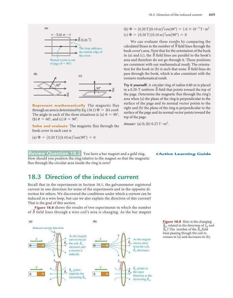
QuanTITaTIve exerCIse 18.2 Flux through a book coverA book is positioned in a uniform 0.20-T
u
B field that points from left to right in the plane of the page, shown in the figures on the next page. (For simplicity, we depict the book as a rectangular loop.) Each side of the book’s cover measures 0.10 m. Determine the
magnetic flux through the cover when (a) the cover is in the plane of the page (figure a), (b) the cover is perpendicular to the plane of the page and the normal vector makes a 60� angle with the
u
B field (figure b), and (c) the book’s cover area is perpendicular to the plane of the page and the normal vector points toward the top of the page (figure c).
M18_VANH5357_01_SE_C18.indd 668 19/07/13 10:19 AM
18.3 Direction of the induced current 669
Review Question 18.2 You have a bar magnet and a gold ring. How should you position the ring relative to the magnet so that the magnetic flux through the circular area inside the ring is zero?
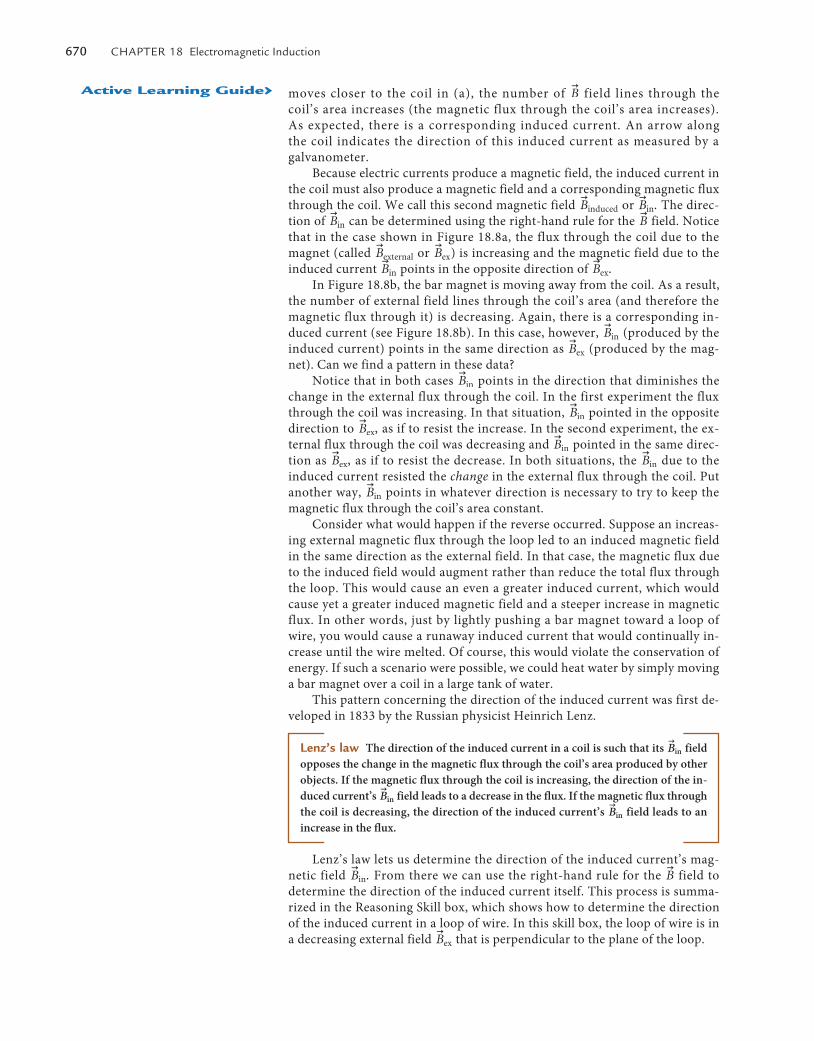
18.3 direction of the induced currentRecall that in the experiments in Section 18.1, the galvanometer registered current in one direction for some of the experiments and in the opposite di-rection for others. We discovered the conditions under which a current can be induced in a wire loop, but can we also explain the direction of this current? That is the goal of this section.
Figure 18.8 shows the results of two experiments in which the number of
u
B field lines through a wire coil’s area is changing. As the bar magnet
represent mathematically The magnetic flux through an area is determined by Eq. (18.1) � = BA cos u. The angle in each of the three situations is (a) u = 90�, (b) u = 60�, and (c) u = 90�.
solve and evaluate The magnetic flux through the book cover in each case is
(a) � = 10.20 T210.10 m22cos190�2 = 0
(b) � = 10.20 T210.10 m22cos160�2 = 1.0 * 10- 3 T # m2
(c) � = 10.20 T210.10 m22cos190�2 = 0
We can evaluate these results by comparing the calculated fluxes to the number of
u
B field lines through the book cover’s area. Note that for the orientation of the book in (a) and (c), the
u
B field lines are parallel to the book’s area and therefore do not go through it. Those positions are consistent with our mathematical result. The orienta-tion for the book in (b) is such that some
u
B field lines do pass through the book, which is also consistent with the nonzero mathematical result.
Try it yourself: A circular ring of radius 0.60 m is placed in a 0.20-T uniform
u
B field that points toward the top of the page. Determine the magnetic flux through the ring’s area when (a) the plane of the ring is perpendicular to the surface of the page and its normal vector points to the right and (b) the plane of the ring is perpendicular to the surface of the page and its normal vector points toward the top of the page.
Answer: (a) 0; (b) 0.23 T # m2.
(c)(b)
Normal vector is outof page (u � 90�)
The loop indicatesthe outside edge ofthe cover.
(a)
Figure 18.8 How is the changing u
Bex related to the direction of Iin and u
Bin? The number of the u
Bexfield lines passing though the coil in-creases in (a) and decreases in (b).
NS
(a)
Induced current directionIin
rvAs the magnetmoves toward the coil, Bex
increases anda current isinduced.
r
r
r
Bin pointsopposite theincreasing Bex.
Iin
rv
NS
(b)
rv
NS
As the magnetmoves away from the coil, Bex decreases.r
r
r
Bin points in the same direction as the decreasing Bex.
Iin
rv
NS
Bex
r
Bin
rBin
r
Bex
r
‹active learning Guide
M18_VANH5357_01_SE_C18.indd 669 19/07/13 10:19 AM
670 Chapter 18 electromagnetic Induction
moves closer to the coil in (a), the number of u
B field lines through the coil’s area increases (the magnetic flux through the coil’s area increases). As expected, there is a corresponding induced current. An arrow along the coil indicates the direction of this induced current as measured by a galvanometer.
Because electric currents produce a magnetic field, the induced current in the coil must also produce a magnetic field and a corresponding magnetic flux through the coil. We call this second magnetic field
u
Binduced or u
Bin. The direc-tion of
u
Bin can be determined using the right-hand rule for the u
B field. Notice that in the case shown in Figure 18.8a, the flux through the coil due to the magnet (called
u
Bexternal or u
Bex) is increasing and the magnetic field due to the induced current
u
Bin points in the opposite direction of u
Bex.In Figure 18.8b, the bar magnet is moving away from the coil. As a result,
the number of external field lines through the coil’s area (and therefore the magnetic flux through it) is decreasing. Again, there is a corresponding in-duced current (see Figure 18.8b). In this case, however,
u
Bin (produced by the induced current) points in the same direction as
u
Bex (produced by the mag-net). Can we find a pattern in these data?
Notice that in both cases u
Bin points in the direction that diminishes the change in the external flux through the coil. In the first experiment the flux through the coil was increasing. In that situation,
u
Bin pointed in the opposite direction to
u
Bex, as if to resist the increase. In the second experiment, the ex-ternal flux through the coil was decreasing and
u
Bin pointed in the same direc-tion as
u
Bex, as if to resist the decrease. In both situations, the u
Bin due to the induced current resisted the change in the external flux through the coil. Put another way,
u
Bin points in whatever direction is necessary to try to keep the magnetic flux through the coil’s area constant.
Consider what would happen if the reverse occurred. Suppose an increas-ing external magnetic flux through the loop led to an induced magnetic field in the same direction as the external field. In that case, the magnetic flux due to the induced field would augment rather than reduce the total flux through the loop. This would cause an even a greater induced current, which would cause yet a greater induced magnetic field and a steeper increase in magnetic flux. In other words, just by lightly pushing a bar magnet toward a loop of wire, you would cause a runaway induced current that would continually in-crease until the wire melted. Of course, this would violate the conservation of energy. If such a scenario were possible, we could heat water by simply moving a bar magnet over a coil in a large tank of water.
This pattern concerning the direction of the induced current was first de-veloped in 1833 by the Russian physicist Heinrich Lenz.
Lenz’s law The direction of the induced current in a coil is such that its u
Bin field opposes the change in the magnetic flux through the coil’s area produced by other objects. If the magnetic flux through the coil is increasing, the direction of the in-duced current’s
u
Bin field leads to a decrease in the flux. If the magnetic flux through the coil is decreasing, the direction of the induced current’s
u
Bin field leads to an increase in the flux.
Lenz’s law lets us determine the direction of the induced current’s mag-netic field
u
Bin. From there we can use the right-hand rule for the u
B field to determine the direction of the induced current itself. This process is summa-rized in the Reasoning Skill box, which shows how to determine the direction of the induced current in a loop of wire. In this skill box, the loop of wire is in a decreasing external field
u
Bex that is perpendicular to the plane of the loop.
active learning Guide›
M18_VANH5357_01_SE_C18.indd 670 19/07/13 10:19 AM
18.3 Direction of the induced current 671
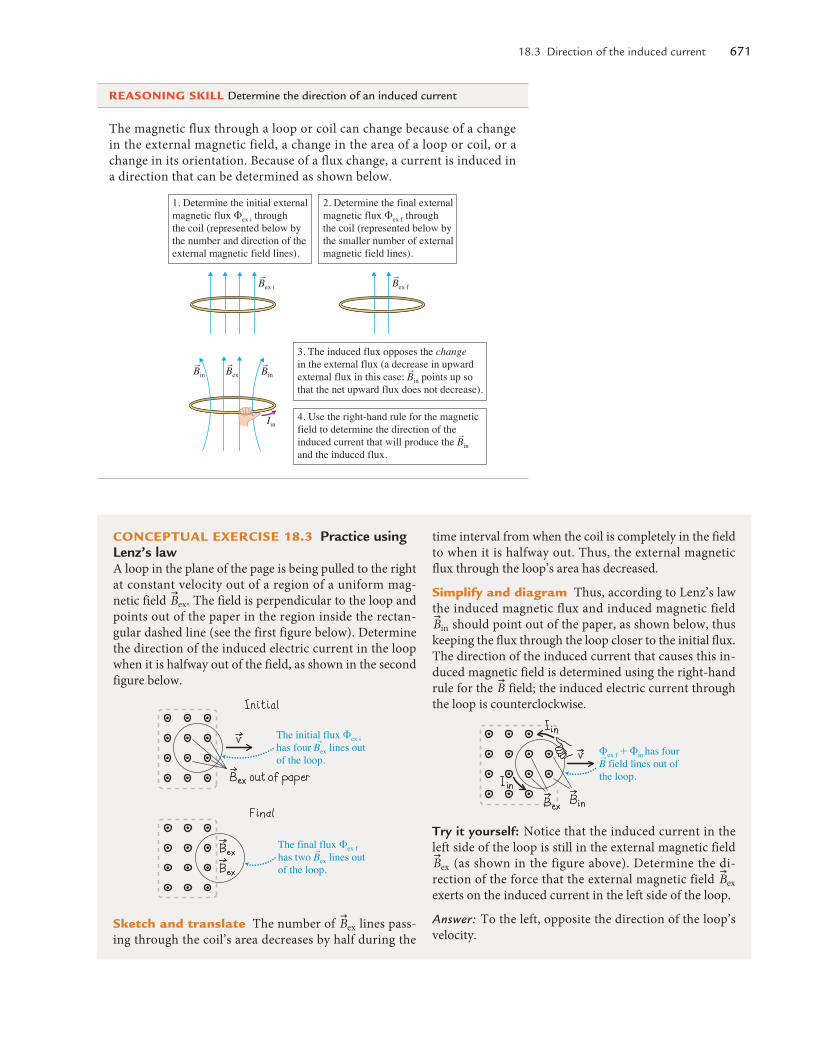
COnCepTual exerCIse 18.3 Practice using Lenz’s lawA loop in the plane of the page is being pulled to the right at constant velocity out of a region of a uniform mag-netic field
u
Bex. The field is perpendicular to the loop and points out of the paper in the region inside the rectan-gular dashed line (see the first figure below). Determine the direction of the induced electric current in the loop when it is halfway out of the field, as shown in the second figure below.
The initial flux �ex i has four Bex lines outof the loop.
r
The final flux �ex f has two Bex lines outof the loop.
r
sketch and translate The number of u
Bex lines pass-ing through the coil’s area decreases by half during the
time interval from when the coil is completely in the field to when it is halfway out. Thus, the external magnetic flux through the loop’s area has decreased.
simplify and diagram Thus, according to Lenz’s law the induced magnetic flux and induced magnetic field u
Bin should point out of the paper, as shown below, thus keeping the flux through the loop closer to the initial flux. The direction of the induced current that causes this in-duced magnetic field is determined using the right-hand rule for the
u
B field; the induced electric current through the loop is counterclockwise.
�ex f � �in has four B field lines out of the loop.
r
Try it yourself: Notice that the induced current in the left side of the loop is still in the external magnetic field u
Bex (as shown in the figure above). Determine the di-rection of the force that the external magnetic field
u
Bex exerts on the induced current in the left side of the loop.
Answer: To the left, opposite the direction of the loop’s velocity.
The magnetic flux through a loop or coil can change because of a change in the external magnetic field, a change in the area of a loop or coil, or a change in its orientation. Because of a flux change, a current is induced in a direction that can be determined as shown below.
reasOnInG skIll Determine the direction of an induced current
1. Determine the initial externalmagnetic flux �ex i throughthe coil (represented below bythe number and direction of theexternal magnetic field lines).
2. Determine the final externalmagnetic flux �ex f throughthe coil (represented below bythe smaller number of externalmagnetic field lines).
3. The induced flux opposes the changein the external flux (a decrease in upwardexternal flux in this case; Bin points up sothat the net upward flux does not decrease).
4. Use the right-hand rule for the magneticfield to determine the direction of theinduced current that will produce the Binand the induced flux.
rBex irBex f
rBin
r
rrBin
rBex
Iin
M18_VANH5357_01_SE_C18.indd 671 19/07/13 10:19 AM
672 Chapter 18 electromagnetic Induction
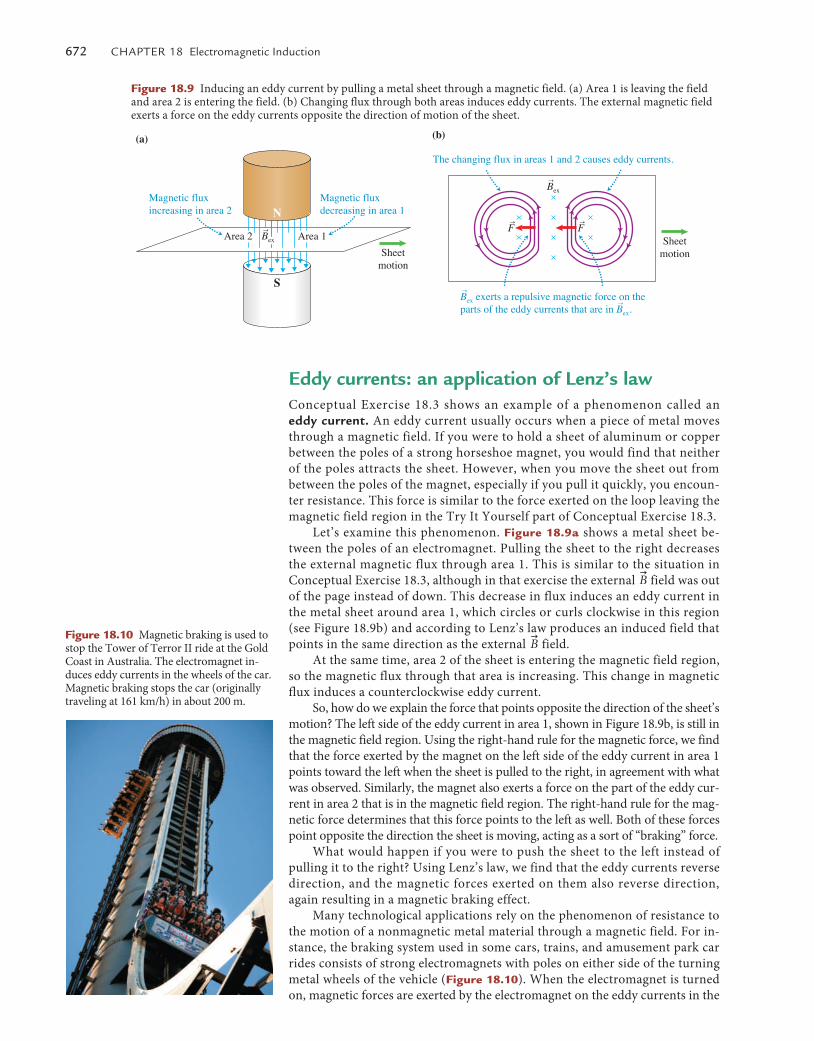
Eddy currents: an application of Lenz’s lawConceptual Exercise 18.3 shows an example of a phenomenon called an eddy current. An eddy current usually occurs when a piece of metal moves through a magnetic field. If you were to hold a sheet of aluminum or copper between the poles of a strong horseshoe magnet, you would find that neither of the poles attracts the sheet. However, when you move the sheet out from between the poles of the magnet, especially if you pull it quickly, you encoun-ter resistance. This force is similar to the force exerted on the loop leaving the magnetic field region in the Try It Yourself part of Conceptual Exercise 18.3.
Let’s examine this phenomenon. Figure 18.9a shows a metal sheet be-tween the poles of an electromagnet. Pulling the sheet to the right decreases the external magnetic flux through area 1. This is similar to the situation in Conceptual Exercise 18.3, although in that exercise the external
u
B field was out of the page instead of down. This decrease in flux induces an eddy current in the metal sheet around area 1, which circles or curls clockwise in this region (see Figure 18.9b) and according to Lenz’s law produces an induced field that points in the same direction as the external
u
B field.At the same time, area 2 of the sheet is entering the magnetic field region,
so the magnetic flux through that area is increasing. This change in magnetic flux induces a counterclockwise eddy current.
So, how do we explain the force that points opposite the direction of the sheet’s motion? The left side of the eddy current in area 1, shown in Figure 18.9b, is still in the magnetic field region. Using the right-hand rule for the magnetic force, we find that the force exerted by the magnet on the left side of the eddy current in area 1 points toward the left when the sheet is pulled to the right, in agreement with what was observed. Similarly, the magnet also exerts a force on the part of the eddy cur-rent in area 2 that is in the magnetic field region. The right-hand rule for the mag-netic force determines that this force points to the left as well. Both of these forces point opposite the direction the sheet is moving, acting as a sort of “braking” force.
What would happen if you were to push the sheet to the left instead of pulling it to the right? Using Lenz’s law, we find that the eddy currents reverse direction, and the magnetic forces exerted on them also reverse direction, again resulting in a magnetic braking effect.
Many technological applications rely on the phenomenon of resistance to the motion of a nonmagnetic metal material through a magnetic field. For in-stance, the braking system used in some cars, trains, and amusement park car rides consists of strong electromagnets with poles on either side of the turning metal wheels of the vehicle (Figure 18.10). When the electromagnet is turned on, magnetic forces are exerted by the electromagnet on the eddy currents in the
S
Sheetmotion
Sheetmotion
Area 2 Area 1
(a)
(b)
The changing flux in areas 1 and 2 causes eddy currents.
Magnetic fluxincreasing in area 2
Magnetic fluxdecreasing in area 1
rBex
Bex exerts a repulsive magnetic force on theparts of the eddy currents that are in Bex.
r
r
rBex
rFrF
N
S
Sheetmotion
Sheetmotion
Area 2 Area 1
(a)
(b)
The changing flux in areas 1 and 2 causes eddy currents.
Magnetic fluxincreasing in area 2
Magnetic fluxdecreasing in area 1
rBex
Bex exerts a repulsive magnetic force on theparts of the eddy currents that are in Bex.
r
r
rBex
rFrF
N
Figure 18.9 Inducing an eddy current by pulling a metal sheet through a magnetic field. (a) Area 1 is leaving the field and area 2 is entering the field. (b) Changing flux through both areas induces eddy currents. The external magnetic field exerts a force on the eddy currents opposite the direction of motion of the sheet.
Figure 18.10 Magnetic braking is used to stop the Tower of Terror II ride at the Gold Coast in Australia. The electromagnet in-duces eddy currents in the wheels of the car. Magnetic braking stops the car (originally traveling at 161 km/h) in about 200 m.
M18_VANH5357_01_SE_C18.indd 672 19/07/13 10:19 AM
18.4 Faraday’s law of electromagnetic induction 673
Observational experiment Analysis
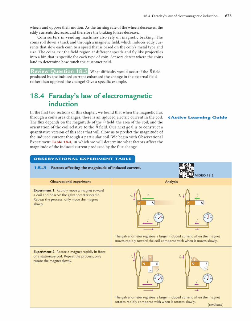
Experiment 1. rapidly move a magnet toward a coil and observe the galvanometer needle. repeat the process, only move the magnet slowly.
rv
I
Iin
N S
rv
I
Iin
N S
the galvanometer registers a larger induced current when the magnet moves rapidly toward the coil compared with when it moves slowly.
Experiment 2. rotate a magnet rapidly in front of a stationary coil. repeat the process, only rotate the magnet slowly.
I
Iin
N
I
Iin
NS
N S NN
SN S
the galvanometer registers a larger induced current when the magnet rotates rapidly compared with when it rotates slowly.
wheels and oppose their motion. As the turning rate of the wheels decreases, the eddy currents decrease, and therefore the braking forces decrease.
Coin sorters in vending machines also rely on magnetic braking. The coins roll down a track and through a magnetic field, which induces eddy cur-rents that slow each coin to a speed that is based on the coin’s metal type and size. The coins exit the field region at different speeds and fly like projectiles into a bin that is specific for each type of coin. Sensors detect where the coins land to determine how much the customer paid.
Review Question 18.3 What difficulty would occur if the u
B field produced by the induced current enhanced the change in the external field rather than opposed the change? Give a specific example.
18.4 Faraday’s law of electromagnetic induction
In the first two sections of this chapter, we found that when the magnetic flux through a coil’s area changes, there is an induced electric current in the coil. The flux depends on the magnitude of the
u
B field, the area of the coil, and the orientation of the coil relative to the
u
B field. Our next goal is to construct a quantitative version of this idea that will allow us to predict the magnitude of the induced current through a particular coil. We begin with Observational Experiment Table 18.3, in which we will determine what factors affect the magnitude of the induced current produced by the flux change.
VIdEO 18.3
ObservaTIOnal experImenT Table
18.3 Factors affecting the magnitude of induced current.
(continued)
‹active learning Guide
M18_VANH5357_01_SE_C18.indd 673 19/07/13 10:19 AM
674 Chapter 18 electromagnetic Induction
Observational experiment Analysis
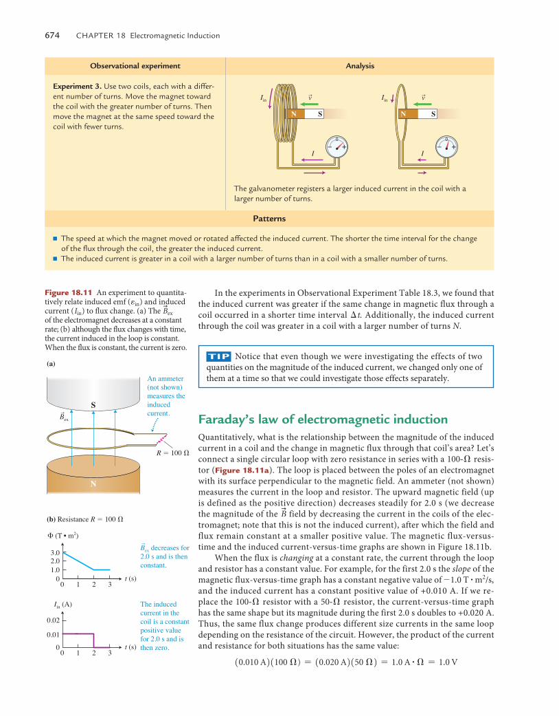
Experiment 3. Use two coils, each with a differ-ent number of turns. Move the magnet toward the coil with the greater number of turns. then move the magnet at the same speed toward the coil with fewer turns.
rv
I
N S S
rv
I
IinIin
N
the galvanometer registers a larger induced current in the coil with a larger number of turns.
Patterns
■ the speed at which the magnet moved or rotated affected the induced current. the shorter the time interval for the change of the flux through the coil, the greater the induced current.
■ the induced current is greater in a coil with a larger number of turns than in a coil with a smaller number of turns.
In the experiments in Observational Experiment Table 18.3, we found that the induced current was greater if the same change in magnetic flux through a coil occurred in a shorter time interval �t. Additionally, the induced current through the coil was greater in a coil with a larger number of turns N.
TIp Notice that even though we were investigating the effects of two quantities on the magnitude of the induced current, we changed only one of them at a time so that we could investigate those effects separately.
(b) Resistance R � 100 �
R � 100 �
An ammeter(not shown)measures theinducedcurrent.
Bex decreases for2.0 s and is thenconstant.
r
S
(a)
N
� (T • m2)
t (s)01.02.03.0
10 2 3
The inducedcurrent in thecoil is a constantpositive valuefor 2.0 s and isthen zero.
Iin (A)
t (s)0
0.01
0.02
10 2 3
rBex
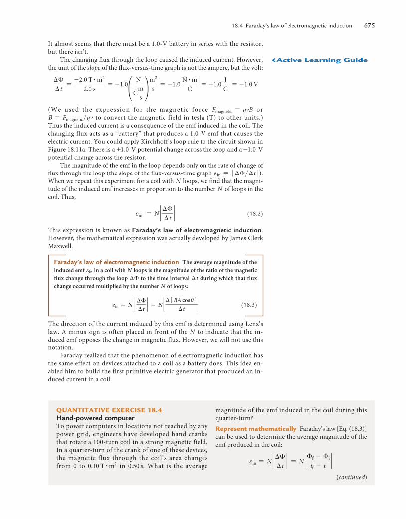
Figure 18.11 An experiment to quantita-tively relate induced emf (ein) and induced current (Iin) to flux change. (a) The
u
Bexof the electromagnet decreases at a constant rate; (b) although the flux changes with time, the current induced in the loop is constant. When the flux is constant, the current is zero.
Faraday’s law of electromagnetic inductionQuantitatively, what is the relationship between the magnitude of the induced current in a coil and the change in magnetic flux through that coil’s area? Let’s connect a single circular loop with zero resistance in series with a 100@� resis-tor (Figure 18.11a). The loop is placed between the poles of an electromagnet with its surface perpendicular to the magnetic field. An ammeter (not shown) measures the current in the loop and resistor. The upward magnetic field (up is defined as the positive direction) decreases steadily for 2.0 s (we decrease the magnitude of the
u
B field by decreasing the current in the coils of the elec-tromagnet; note that this is not the induced current), after which the field and flux remain constant at a smaller positive value. The magnetic flux-versus-time and the induced current-versus-time graphs are shown in Figure 18.11b.
When the flux is changing at a constant rate, the current through the loop and resistor has a constant value. For example, for the first 2.0 s the slope of the magnetic flux-versus-time graph has a constant negative value of -1.0 T # m2/s, and the induced current has a constant positive value of +0.010 A. If we re-place the 100@� resistor with a 50@� resistor, the current-versus-time graph has the same shape but its magnitude during the first 2.0 s doubles to +0.020 A. Thus, the same flux change produces different size currents in the same loop depending on the resistance of the circuit. However, the product of the current and resistance for both situations has the same value:
10.010 A21100 �) = 10.020 A2150 �2 = 1.0 A # � = 1.0 V
M18_VANH5357_01_SE_C18.indd 674 19/07/13 10:19 AM
18.4 Faraday’s law of electromagnetic induction 675
It almost seems that there must be a 1.0-V battery in series with the resistor, but there isn’t.
The changing flux through the loop caused the induced current. However, the unit of the slope of the flux-versus-time graph is not the ampere, but the volt:
��
�t=
-2.0 T # m2
2.0 s= -1.0°
N
Cm
s¢
m2
s= -1.0
N # m
C = -1.0
J
C = -1.0 V
(We used the expression for the magnetic force Fmagnetic = qvB or B = Fmagnetic>qv to convert the magnetic field in tesla (T) to other units.) Thus the induced current is a consequence of the emf induced in the coil. The changing flux acts as a “battery” that produces a 1.0-V emf that causes the electric current. You could apply Kirchhoff’s loop rule to the circuit shown in Figure 18.11a. There is a +1.0-V potential change across the loop and a -1.0-V potential change across the resistor.
The magnitude of the emf in the loop depends only on the rate of change of flux through the loop (the slope of the flux-versus-time graph ein = � ��>�t � ). When we repeat this experiment for a coil with N loops, we find that the magni-tude of the induced emf increases in proportion to the number N of loops in the coil. Thus,
ein = N ` ��
�t` (18.2)
This expression is known as Faraday’s law of electromagnetic induction. However, the mathematical expression was actually developed by James Clerk Maxwell.
Faraday’s law of electromagnetic induction The average magnitude of the induced emf ein in a coil with N loops is the magnitude of the ratio of the magnetic flux change through the loop �� to the time interval �t during which that flux change occurred multiplied by the number N of loops:
ein = N ` ��
�t` = N ` � 3BA cos u4
�t` (18.3)
The direction of the current induced by this emf is determined using Lenz’s law. A minus sign is often placed in front of the N to indicate that the in-duced emf opposes the change in magnetic flux. However, we will not use this notation.
Faraday realized that the phenomenon of electromagnetic induction has the same effect on devices attached to a coil as a battery does. This idea en-abled him to build the first primitive electric generator that produced an in-duced current in a coil.
QuanTITaTIve exerCIse 18.4 Hand-powered computerTo power computers in locations not reached by any power grid, engineers have developed hand cranks that rotate a 100-turn coil in a strong magnetic field. In a quarter-turn of the crank of one of these devices, the magnetic flux through the coil’s area changes from 0 to 0.10 T # m2 in 0.50 s. What is the average
magnitude of the emf induced in the coil during this quarter-turn?represent mathematically Faraday’s law [Eq. (18.3)] can be used to determine the average magnitude of the emf produced in the coil:
ein = N ` ��
�t` = N ` �f - �i
tf - ti`
(continued)
‹active learning Guide
M18_VANH5357_01_SE_C18.indd 675 19/07/13 10:19 AM
676 Chapter 18 electromagnetic Induction
solve and evaluate Inserting the appropriate values, we find:
ein = 11002 ` 10.10 T # m22 - 0
0.50 s - 0` = 20 V
The magnitude of this emf is about what is required by laptop computers. However, the computer only works while the coil is turning. Laptops typically have a power
requirement of about 50 watts (50 joules each second), which means considerable strength and endurance would be needed to keep the coil rotating.
Try it yourself: Determine the average emf produced in the coil if you turn the coil one quarter-turn in 1.0 s in-stead of in 0.50 s.
Answer: 10 V.
Review Question 18.4 Why do we write the law of electromag-netic induction in terms of emf rather than in terms of induced current?
18.5 Skills for analyzing processes involving electromagnetic induction
Faraday’s law enables us to design and understand practical applications of electromagnetic induction. For example, to design an automobile ignition sys-tem that uses spark plugs, engineers must estimate how quickly the magnetic field through a coil must be reduced to zero to produce a large enough emf to ignite a spark plug. An engineer designing an electric generator will be inter-ested in the rate at which the generator coil must turn relative to the
u
B field to produce the desired induced emf. The general strategy for analyzing questions like these is described and illustrated in Example 18.5.
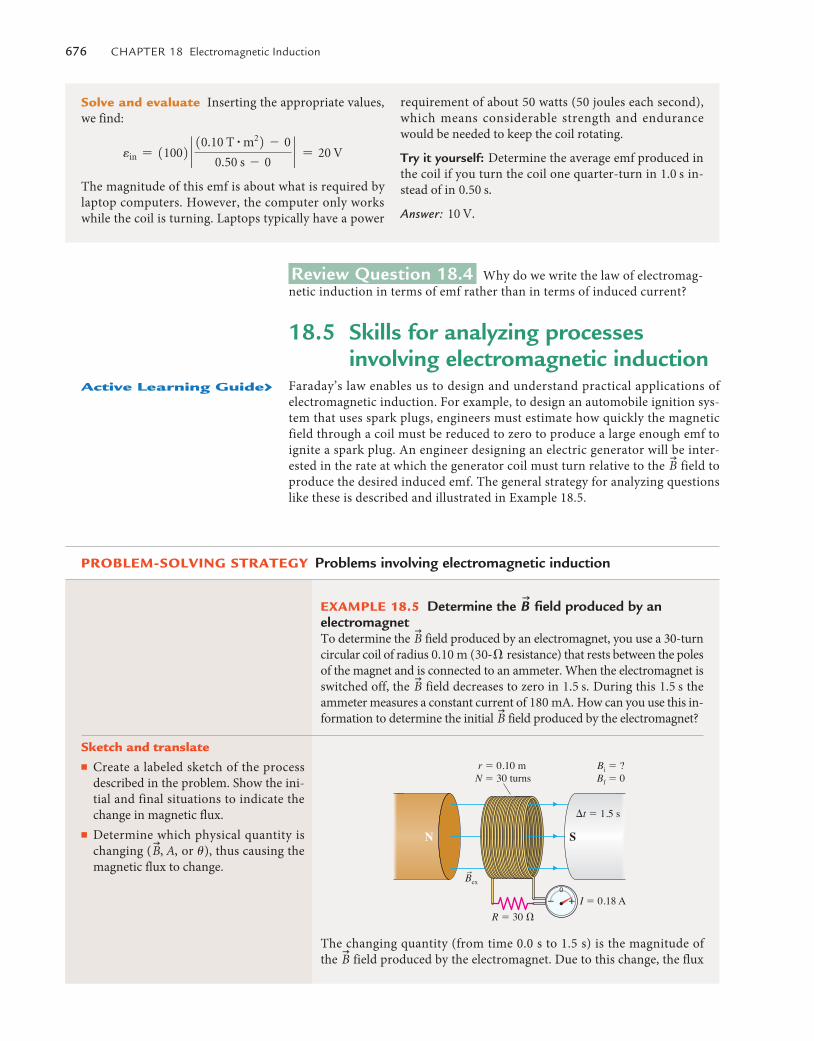
example 18.5 determine the u
B field produced by an electromagnetTo determine the
u
B field produced by an electromagnet, you use a 30-turn circular coil of radius 0.10 m (30@� resistance) that rests between the poles of the magnet and is connected to an ammeter. When the electromagnet is switched off, the
u
B field decreases to zero in 1.5 s. During this 1.5 s the ammeter measures a constant current of 180 mA. How can you use this in-formation to determine the initial
u
B field produced by the electromagnet?
prOblem-sOlvInG sTraTeGy Problems involving electromagnetic induction
r � 0.10 m
I � 0.18 AR � 30 �
�t � 1.5 s
Bi � ?Bf � 0
SN
rBex
N � 30 turns
The changing quantity (from time 0.0 s to 1.5 s) is the magnitude of the
u
B field produced by the electromagnet. Due to this change, the flux
sketch and translate■ Create a labeled sketch of the process
described in the problem. Show the ini-tial and final situations to indicate the change in magnetic flux.
■ Determine which physical quantity is changing (
u
B, A, or u), thus causing the magnetic flux to change.
active learning Guide›
M18_VANH5357_01_SE_C18.indd 676 19/07/13 10:19 AM
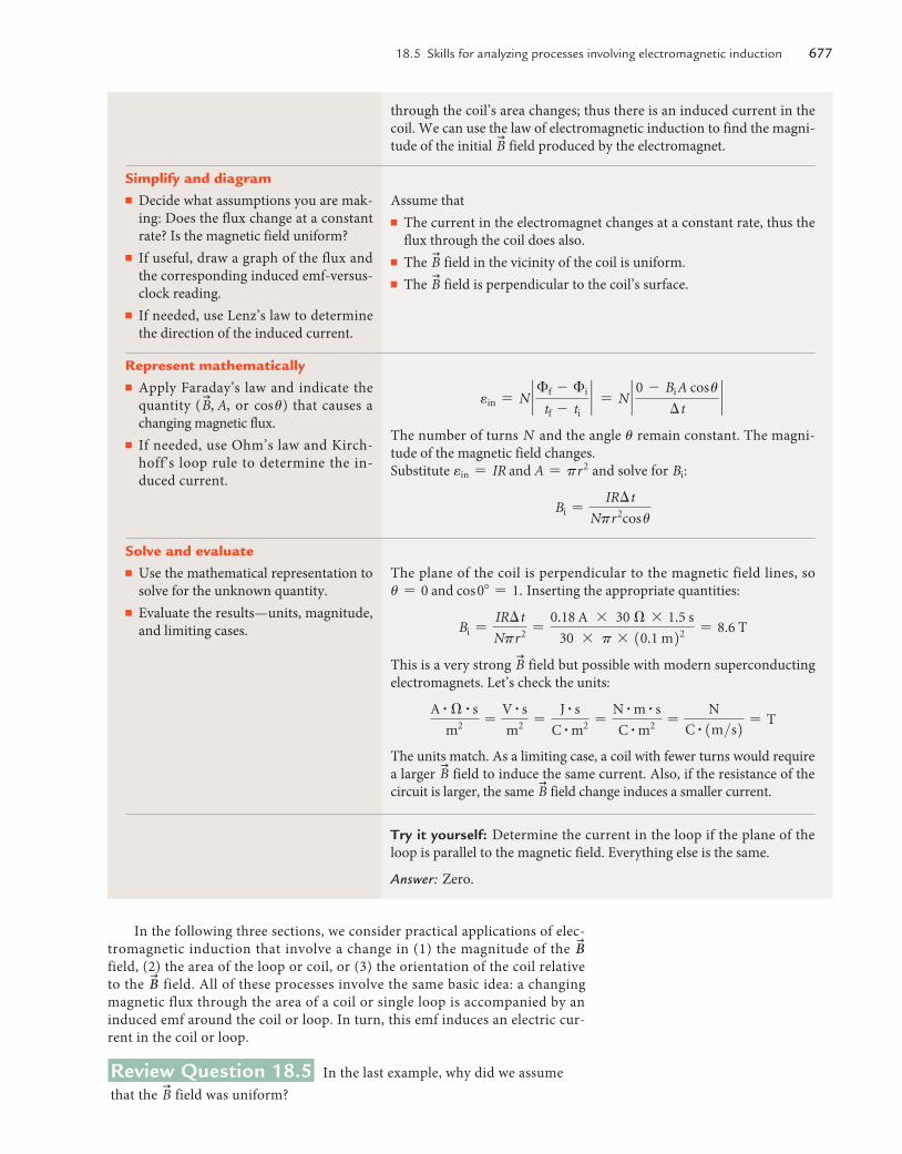
18.5 Skills for analyzing processes involving electromagnetic induction 677
In the following three sections, we consider practical applications of elec-tromagnetic induction that involve a change in (1) the magnitude of the
u
B field, (2) the area of the loop or coil, or (3) the orientation of the coil relative to the
u
B field. All of these processes involve the same basic idea: a changing magnetic flux through the area of a coil or single loop is accompanied by an induced emf around the coil or loop. In turn, this emf induces an electric cur-rent in the coil or loop.
Review Question 18.5 In the last example, why did we assume that the
u
B field was uniform?
Assume that■ The current in the electromagnet changes at a constant rate, thus the
flux through the coil does also.■ The
u
B field in the vicinity of the coil is uniform.■ The
u
B field is perpendicular to the coil’s surface.
through the coil’s area changes; thus there is an induced current in the coil. We can use the law of electromagnetic induction to find the magni-tude of the initial
u
B field produced by the electromagnet.
simplify and diagram■ Decide what assumptions you are mak-
ing: Does the flux change at a constant rate? Is the magnetic field uniform?
■ If useful, draw a graph of the flux and the corresponding induced emf-versus-clock reading.
■ If needed, use Lenz’s law to determine the direction of the induced current.
ein = N ` �f - �i
tf - ti` = N ` 0 - Bi A cos u
�t`
The number of turns N and the angle u remain constant. The magni-tude of the magnetic field changes.Substitute ein = IR and A = pr 2 and solve for Bi:
Bi =IR�t
Npr 2cos u
represent mathematically■ Apply Faraday’s law and indicate the
quantity (u
B, A, or cos u) that causes a changing magnetic flux.
■ If needed, use Ohm’s law and Kirch-hoff’s loop rule to determine the in-duced current.
The plane of the coil is perpendicular to the magnetic field lines, so u = 0 and cos 0� = 1. Inserting the appropriate quantities:
Bi =IR�t
Npr 2 =0.18 A * 30 � * 1.5 s
30 * p * 10.1 m22 = 8.6 T
This is a very strong u
B field but possible with modern superconducting electromagnets. Let’s check the units:
A # � # s
m2 =V # s
m2 =J # s
C # m2 =N # m # s
C # m2 =N
C # 1m>s2 = T
The units match. As a limiting case, a coil with fewer turns would require a larger
u
B field to induce the same current. Also, if the resistance of the circuit is larger, the same
u
B field change induces a smaller current.
solve and evaluate■ Use the mathematical representation to
solve for the unknown quantity.■ Evaluate the results—units, magnitude,
and limiting cases.
Try it yourself: Determine the current in the loop if the plane of the loop is parallel to the magnetic field. Everything else is the same.
Answer: Zero.
M18_VANH5357_01_SE_C18.indd 677 19/07/13 10:19 AM
678 Chapter 18 electromagnetic Induction
18.6 Changing u
B field magnitude and induced emf
We have learned that a current is induced in a coil (or single loop, or electri-cally conductive region in the case of eddy currents) when the magnetic flux through the coil’s area changes. In this section, we consider examples where the flux change is due to a change in the magnitude of the
u
B field throughout the coil’s area. This is the case in transcranial magnetic stimulation (TMS), which we investigated qualitatively earlier in this chapter.
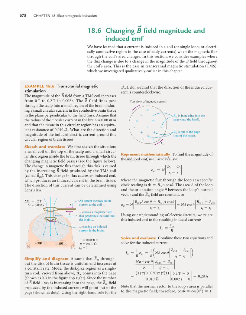
example 18.6 Transcranial magnetic stimulationThe magnitude of the
u
B field from a TMS coil increases from 0 T to 0.2 T in 0.002 s. The
u
B field lines pass through the scalp into a small region of the brain, induc-ing a small circular current in the conductive brain tissue in the plane perpendicular to the field lines. Assume that the radius of the circular current in the brain is 0.0030 m and that the tissue in this circular region has an equiva-lent resistance of 0.010 �. What are the direction and magnitude of the induced electric current around this circular region of brain tissue?
sketch and translate We first sketch the situation: a small coil on the top of the scalp and a small circu-lar disk region inside the brain tissue through which the changing magnetic field passes (see the figure below). The change in magnetic flux through this disk is caused by the increasing
u
B field produced by the TMS coil (called
u
Bex). This change in flux causes an induced emf, which produces an induced current in the brain tissue. The direction of this current can be determined using Lenz’s law.
r � 0.0030 m
�Bex � 0.2 T
I
IAn abrupt increase in thecurrent to the coil ...
... causes a magnetic fieldthat penetrates the skull intothe brain ...
... causing an induced current in the brain.
Iin
R � 0.010 �Iin � ?
�t � 0.002 s
simplify and diagram Assume that u
Bex through-out the disk of brain tissue is uniform and increases at a constant rate. Model the disk-like region as a single-turn coil. Viewed from above,
u
Bex points into the page (shown as X’s in the figure top right). Since the number of
u
B field lines is increasing into the page, the u
Bin field produced by the induced current will point out of the page (shown as dots). Using the right-hand rule for the
u
Bin field, we find that the direction of the induced cur-rent is counterclockwise.
Top view of induced current
Iin
Bex is increasing into thepage (into the head).
r
Bin is out of the page(out of the head).
r
represent mathematically To find the magnitude of the induced emf, use Faraday’s law:
ein = N ` �f - �i
tf - ti`
where the magnetic flux through the loop at a specific clock reading is � = BexA cos u. The area A of the loop and the orientation angle u between the loop’s normal vector and the
u
Bex field are constant, so
ein = N ` Bex fA cos u - Bex iA cos u
tf - ti` = NA cos u ` Bex f - Bex i
tf - ti`
Using our understanding of electric circuits, we relate this induced emf to the resulting induced current:
Iin =ein
R
solve and evaluate Combine these two equations and solve for the induced current:
Iin =1
R ein =
1
RaNA cos u ` Bex f - Bex i
tf - ti` b
=Npr 2 cos u
R` Bex f - Bex i
tf - ti`
=112p10.0030 m22112
0.010 �` 0.2 T - 0
0.002 s - 0` = 0.28 A
Note that the normal vector to the loop’s area is parallel to the magnetic field; therefore, cos u = cos10�2 = 1.
M18_VANH5357_01_SE_C18.indd 678 19/07/13 10:19 AM
18.7 Changing area and induced emf 679
Review Question 18.6 How can a coil of wire, a battery, and a switch placed outside a patient’s head produce electric currents in the brain?
18.7 Changing area and induced emfWhen located in a region with nonzero
u
B field, a change in a coil’s area also results in a change in the magnetic flux through that area. There is then a corre-sponding induced emf producing an induced electric current circling the area.
This is a significant current and could affect brain func-tion in that region of the brain.
Try it yourself: A circular coil of radius 0.020 m with 200 turns lies so that its area is parallel to this page. A bar magnet above the coil is oriented perpendicular to the coil’s area, its north pole facing toward the coil. You quickly (in 0.050 s) move the bar magnet sideways away
from the coil to a location far away. During this 0.050 s, the magnitude of the
u
B field throughout the coil’s area changes from 0.40 T to nearly 0 T. Determine the average magnitude of the induced emf around the coil while the bar magnet is being moved away.
Answer: 2.0 V.
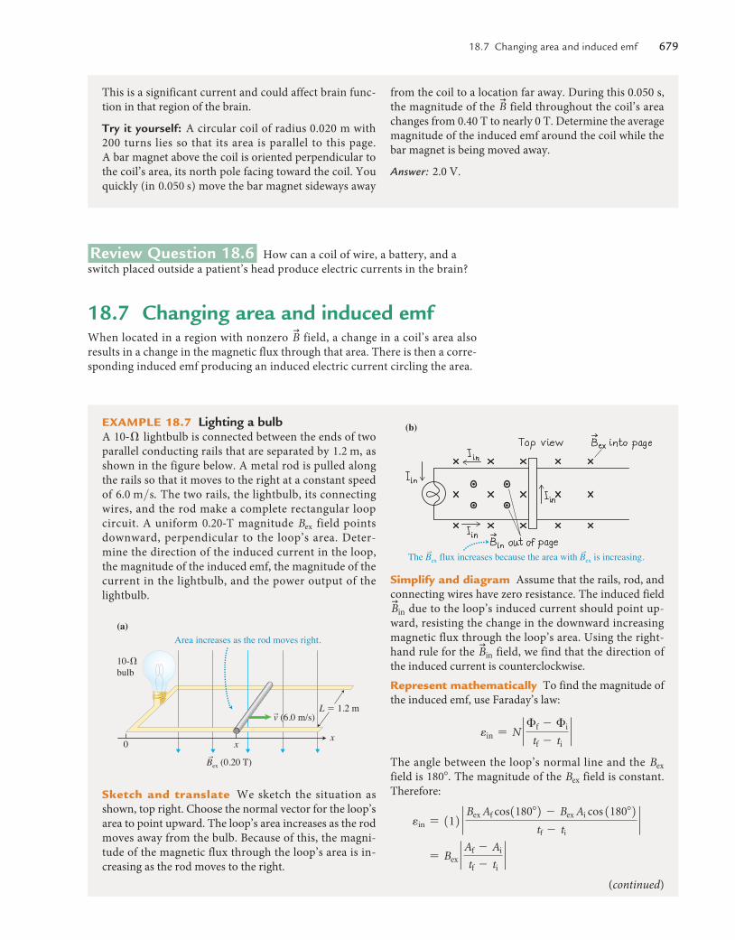
example 18.7 Lighting a bulbA 10@� lightbulb is connected between the ends of two parallel conducting rails that are separated by 1.2 m, as shown in the figure below. A metal rod is pulled along the rails so that it moves to the right at a constant speed of 6.0 m>s. The two rails, the lightbulb, its connecting wires, and the rod make a complete rectangular loop circuit. A uniform 0.20@T magnitude Bex field points downward, perpendicular to the loop’s area. Deter-mine the direction of the induced current in the loop, the magnitude of the induced emf, the magnitude of the current in the lightbulb, and the power output of the lightbulb.
10-�bulb
Bex (0.20 T)
(a)Area increases as the rod moves right.
L � 1.2 m
x0 x
r
v (6.0 m/s)r
sketch and translate We sketch the situation as shown, top right. Choose the normal vector for the loop’s area to point upward. The loop’s area increases as the rod moves away from the bulb. Because of this, the magni-tude of the magnetic flux through the loop’s area is in-creasing as the rod moves to the right.
(b)
The Bex flux increases because the area with Bex is increasing.r r
simplify and diagram Assume that the rails, rod, and connecting wires have zero resistance. The induced field u
Bin due to the loop’s induced current should point up-ward, resisting the change in the downward increasing magnetic flux through the loop’s area. Using the right-hand rule for the
u
Bin field, we find that the direction of the induced current is counterclockwise.represent mathematically To find the magnitude of the induced emf, use Faraday’s law:
ein = N ` �f - �i
tf - ti`
The angle between the loop’s normal line and the Bex field is 180�. The magnitude of the Bex field is constant. Therefore:
ein = 112 ` Bex Af cos1180�2 - Bex Ai cos 1180�2tf - ti
`
= Bex `Af - Ai
tf - ti`
(continued)
M18_VANH5357_01_SE_C18.indd 679 19/07/13 10:19 AM
680 Chapter 18 electromagnetic Induction
I
II
I
II
(a)
(b)
The magneticfield exertsa magneticforce on freeelectrons inthe moving rod.
The magneticforce causesexcess electronsto accumulateat I.
The oppositecharges at I and IIproduce an electric force that balancesthe magnetic force.
Bex into pager
rv
�����
�����
I
II(c)
�����
�����
FB on q � qvBr
rrFB on q
rFE on q � qE
I
II
I
II
(a)
(b)
The magneticfield exertsa magneticforce on freeelectrons inthe moving rod.
The magneticforce causesexcess electronsto accumulateat I.
The oppositecharges at I and IIproduce an electric force that balancesthe magnetic force.
Bex into pager
rv
�����
�����
I
II(c)
�����
�����
FB on q � qvBr
rrFB on q
rFE on q � qE
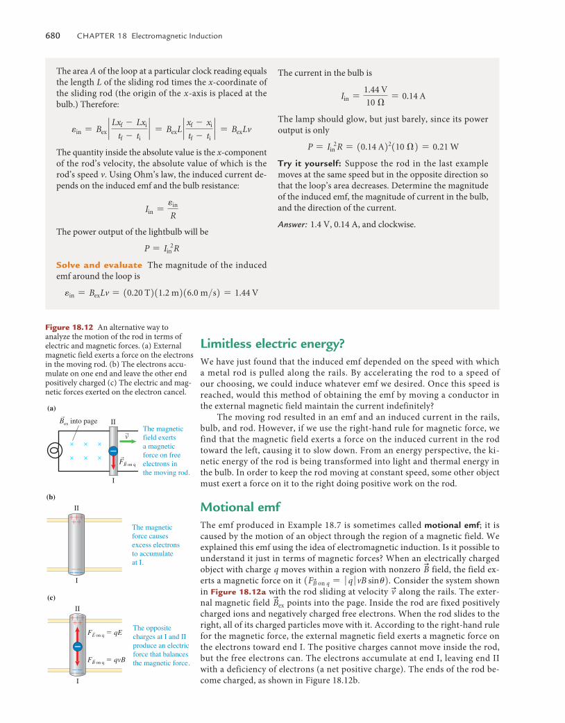
Figure 18.12 An alternative way to analyze the motion of the rod in terms of electric and magnetic forces. (a) External magnetic field exerts a force on the electrons in the moving rod. (b) The electrons accu-mulate on one end and leave the other end positively charged (c) The electric and mag-netic forces exerted on the electron cancel.
Limitless electric energy?We have just found that the induced emf depended on the speed with which a metal rod is pulled along the rails. By accelerating the rod to a speed of our choosing, we could induce whatever emf we desired. Once this speed is reached, would this method of obtaining the emf by moving a conductor in the external magnetic field maintain the current indefinitely?
The moving rod resulted in an emf and an induced current in the rails, bulb, and rod. However, if we use the right-hand rule for magnetic force, we find that the magnetic field exerts a force on the induced current in the rod toward the left, causing it to slow down. From an energy perspective, the ki-netic energy of the rod is being transformed into light and thermal energy in the bulb. In order to keep the rod moving at constant speed, some other object must exert a force on it to the right doing positive work on the rod.
Motional emfThe emf produced in Example 18.7 is sometimes called motional emf; it is caused by the motion of an object through the region of a magnetic field. We explained this emf using the idea of electromagnetic induction. Is it possible to understand it just in terms of magnetic forces? When an electrically charged object with charge q moves within a region with nonzero
u
B field, the field ex-erts a magnetic force on it 1Fu
B on q = � q �vB sin u2. Consider the system shown in Figure 18.12a with the rod sliding at velocity uv along the rails. The exter-nal magnetic field
u
Bex points into the page. Inside the rod are fixed positively charged ions and negatively charged free electrons. When the rod slides to the right, all of its charged particles move with it. According to the right-hand rule for the magnetic force, the external magnetic field exerts a magnetic force on the electrons toward end I. The positive charges cannot move inside the rod, but the free electrons can. The electrons accumulate at end I, leaving end II with a deficiency of electrons (a net positive charge). The ends of the rod be-come charged, as shown in Figure 18.12b.
The area A of the loop at a particular clock reading equals the length L of the sliding rod times the x-coordinate of the sliding rod (the origin of the x-axis is placed at the bulb.) Therefore:
ein = Bex `Lxf - Lxi
tf - ti` = BexL ` xf - xi
tf - ti` = BexLv
The quantity inside the absolute value is the x-component of the rod’s velocity, the absolute value of which is the rod’s speed v. Using Ohm’s law, the induced current de-pends on the induced emf and the bulb resistance:
Iin =ein
R
The power output of the lightbulb will be
P = Iin2R
solve and evaluate The magnitude of the induced emf around the loop is
ein = BexLv = 10.20 T211.2 m216.0 m>s2 = 1.44 V
The current in the bulb is
Iin =1.44 V
10 �= 0.14 A
The lamp should glow, but just barely, since its power output is only
P = Iin2R = 10.14 A22110 �2 = 0.21 W
Try it yourself: Suppose the rod in the last example moves at the same speed but in the opposite direction so that the loop’s area decreases. Determine the magnitude of the induced emf, the magnitude of current in the bulb, and the direction of the current.
Answer: 1.4 V, 0.14 A, and clockwise.
M18_VANH5357_01_SE_C18.indd 680 19/07/13 10:19 AM
18.8 Changing orientation and induced emf 681
These separated charges create an electric field u
E in the rod that exerts a force of magnitude Fu
E on q = qE on other electrons in the rod; the electric field exerts a force on negative electrons toward II (Figure 18.12c) opposite the direction of the magnetic force. When the magnitude of the electric force equals the magnitude of the magnetic force, the accumulation of opposite elec-tric charge at the ends of the rod ceases. Then,
qvB = qE or E = vB
An electric potential difference is produced between points I and II that depends on the magnitude of the electric field
u
E in the rod and the distance L between ends I and II:
emotional emf = � �VI - II � = EL = vBL (18.4)
The above expression for motional emf is the same expression we derived in Example 18.7 using Faraday’s law. Thus, for problems involving conduct-ing objects moving in a magnetic field, we can use either Faraday’s law or the motional emf expression to determine the emf produced—either method will provide the same result.
Review Question 18.7 Suppose the rod in Example 18.7 was one-third the length and the magnetic field was four-fifths the magnitude. How fast would the rod need to move to produce the same emf? Would the current induced in this case be the same as for Example 18.7? Explain.
18.8 Changing orientation and induced emf
In the previous two sections, we investigated processes where emf was induced when the magnitude of the
u
B field changed or when the area of a loop within the
u
B field region changed. In this section we investigate what happens when the orientation of a loop changes relative to the direction of the
u
B field. This process has many practical applications, the most important being the electric generator.
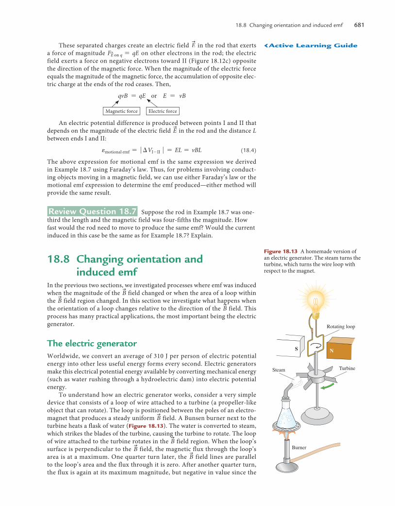
The electric generatorWorldwide, we convert an average of 310 J per person of electric potential energy into other less useful energy forms every second. Electric generators make this electrical potential energy available by converting mechanical energy (such as water rushing through a hydroelectric dam) into electric potential energy.
To understand how an electric generator works, consider a very simple device that consists of a loop of wire attached to a turbine (a propeller-like object that can rotate). The loop is positioned between the poles of an electro-magnet that produces a steady uniform
u
B field. A Bunsen burner next to the turbine heats a flask of water (Figure 18.13). The water is converted to steam, which strikes the blades of the turbine, causing the turbine to rotate. The loop of wire attached to the turbine rotates in the
u
B field region. When the loop’s surface is perpendicular to the
u
B field, the magnetic flux through the loop’s area is at a maximum. One quarter turn later, the
u
B field lines are parallel to the loop’s area and the flux through it is zero. After another quarter turn, the flux is again at its maximum magnitude, but negative in value since the
Magnetic force Electric force
Rotating loop
TurbineSteam
Burner
S N
Figure 18.13 A homemade version of an electric generator. The steam turns the turbine, which turns the wire loop with respect to the magnet.
‹active learning Guide
M18_VANH5357_01_SE_C18.indd 681 19/07/13 10:19 AM
682 Chapter 18 electromagnetic Induction
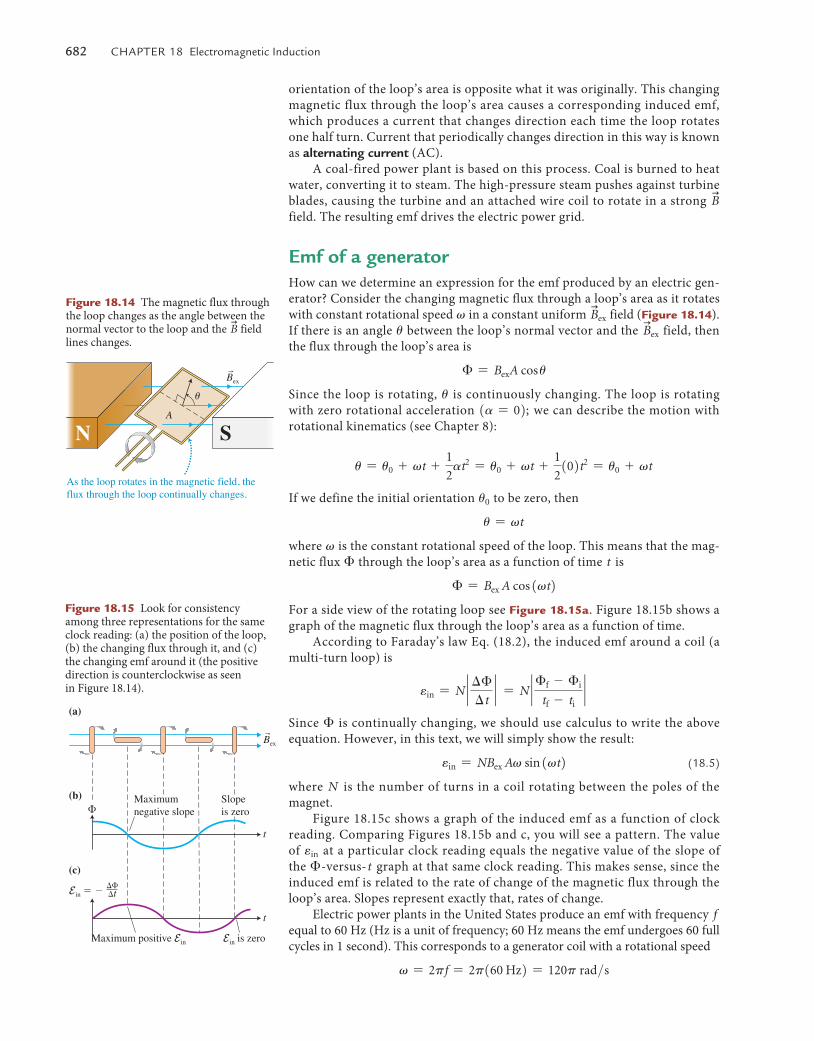
Figure 18.15 Look for consistency among three representations for the same clock reading: (a) the position of the loop, (b) the changing flux through it, and (c) the changing emf around it (the positive direction is counterclockwise as seen in Figure 18.14).
Maximumnegative slope
Maximum positive Ein
Slopeis zero
Ein is zero
�
(a)
(b)
(c)
Ein � ����t
rBex
t
t
orientation of the loop’s area is opposite what it was originally. This changing magnetic flux through the loop’s area causes a corresponding induced emf, which produces a current that changes direction each time the loop rotates one half turn. Current that periodically changes direction in this way is known as alternating current (AC).
A coal-fired power plant is based on this process. Coal is burned to heat water, converting it to steam. The high-pressure steam pushes against turbine blades, causing the turbine and an attached wire coil to rotate in a strong
u
B field. The resulting emf drives the electric power grid.
Emf of a generatorHow can we determine an expression for the emf produced by an electric gen-erator? Consider the changing magnetic flux through a loop’s area as it rotates with constant rotational speed v in a constant uniform
u
Bex field (Figure 18.14). If there is an angle u between the loop’s normal vector and the
u
Bex field, then the flux through the loop’s area is
� = BexA cos u
Since the loop is rotating, u is continuously changing. The loop is rotating with zero rotational acceleration 1a = 02; we can describe the motion with rotational kinematics (see Chapter 8):
u = u0 + vt +1
2at2 = u0 + vt +
1
2102t2 = u0 + vt
If we define the initial orientation u0 to be zero, then
u = vt
where v is the constant rotational speed of the loop. This means that the mag-netic flux � through the loop’s area as a function of time t is
� = Bex A cos 1vt2For a side view of the rotating loop see Figure 18.15a. Figure 18.15b shows a graph of the magnetic flux through the loop’s area as a function of time.
According to Faraday’s law Eq. (18.2), the induced emf around a coil (a multi-turn loop) is
ein = N ` ��
�t` = N ` �f - �i
tf - ti`
Since � is continually changing, we should use calculus to write the above equation. However, in this text, we will simply show the result:
ein = NBex Av sin 1vt2 (18.5)
where N is the number of turns in a coil rotating between the poles of the magnet.
Figure 18.15c shows a graph of the induced emf as a function of clock reading. Comparing Figures 18.15b and c, you will see a pattern. The value of ein at a particular clock reading equals the negative value of the slope of the �-versus-t graph at that same clock reading. This makes sense, since the induced emf is related to the rate of change of the magnetic flux through the loop’s area. Slopes represent exactly that, rates of change.
Electric power plants in the United States produce an emf with frequency f equal to 60 Hz (Hz is a unit of frequency; 60 Hz means the emf undergoes 60 full cycles in 1 second). This corresponds to a generator coil with a rotational speed
v = 2pf = 2p160 Hz2 = 120p rad>s
rBex
A
u
As the loop rotates in the magnetic field, the flux through the loop continually changes.
N S
Figure 18.14 The magnetic flux through the loop changes as the angle between the normal vector to the loop and the
u
B field lines changes.
M18_VANH5357_01_SE_C18.indd 682 19/07/13 10:19 AM
18.9 transformers: putting it all together 683
These power plants can produce a peak (maximum) emf as high as 20 kV. The peak emf produced by a generator occurs when sin1vt2 = 1 and when sin1vt2 = -1. At those times,
ein max = NBex Av. (18.6)
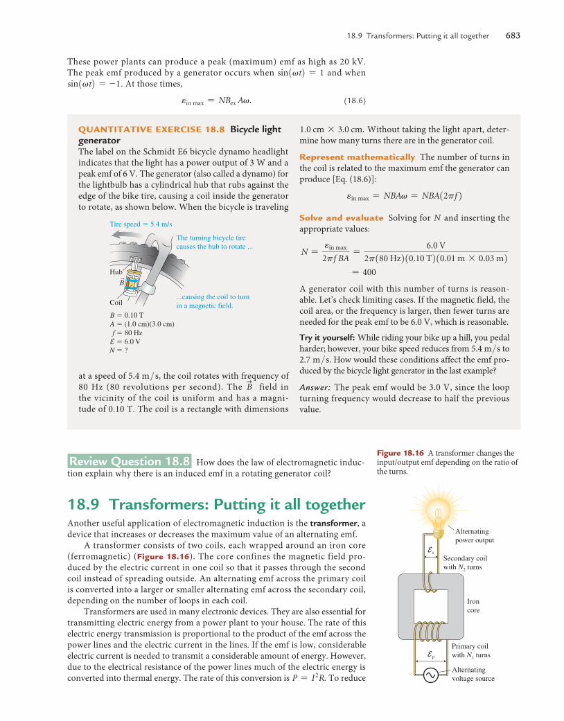
QuanTITaTIve exerCIse 18.8 Bicycle light generatorThe label on the Schmidt E6 bicycle dynamo headlight indicates that the light has a power output of 3 W and a peak emf of 6 V. The generator (also called a dynamo) for the lightbulb has a cylindrical hub that rubs against the edge of the bike tire, causing a coil inside the generator to rotate, as shown below. When the bicycle is traveling
1.0 cm * 3.0 cm. Without taking the light apart, deter-mine how many turns there are in the generator coil.
represent mathematically The number of turns in the coil is related to the maximum emf the generator can produce [Eq. (18.6)]:
ein max = NBAv = NBA12pf 2
solve and evaluate Solving for N and inserting the appropriate values:
N =ein max
2pf BA=
6.0 V
2p180 Hz210.10 T210.01 m * 0.03 m2 = 400
A generator coil with this number of turns is reason-able. Let’s check limiting cases. If the magnetic field, the coil area, or the frequency is larger, then fewer turns are needed for the peak emf to be 6.0 V, which is reasonable.
Try it yourself: While riding your bike up a hill, you pedal harder; however, your bike speed reduces from 5.4 m>s to 2.7 m>s. How would these conditions affect the emf pro-duced by the bicycle light generator in the last example?
Answer: The peak emf would be 3.0 V, since the loop turning frequency would decrease to half the previous value.
Coil
Hub
The turning bicycle tirecauses the hub to rotate ...
Tire speed � 5.4 m/s
...causing the coil to turn in a magnetic field.
rB
B � 0.10 TA � (1.0 cm)(3.0 cm)f � 80 HzE � 6.0 VN � ?
at a speed of 5.4 m > s, the coil rotates with frequency of 80 Hz (80 revolutions per second). The
u
B field in the vicinity of the coil is uniform and has a magni-tude of 0.10 T. The coil is a rectangle with dimensions
Review Question 18.8 How does the law of electromagnetic induc-tion explain why there is an induced emf in a rotating generator coil?
18.9 Transformers: Putting it all togetherAnother useful application of electromagnetic induction is the transformer, a device that increases or decreases the maximum value of an alternating emf.
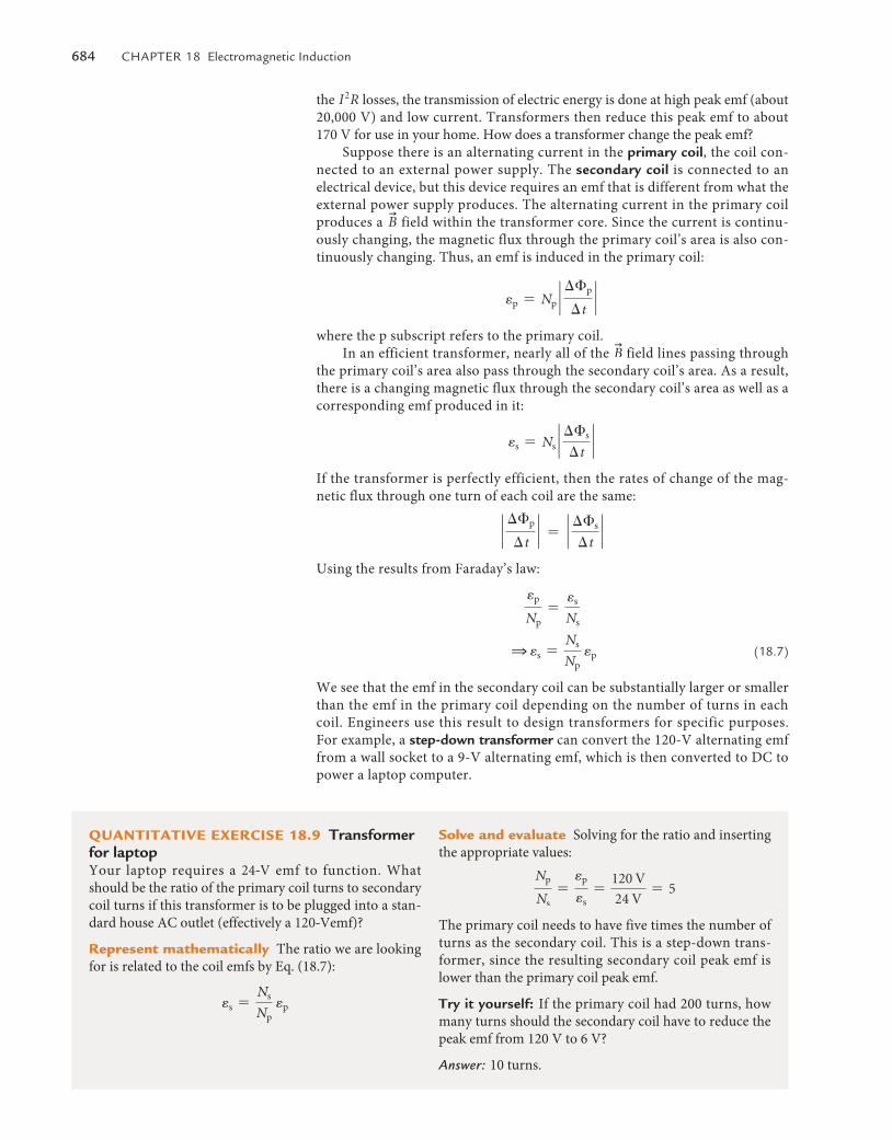
A transformer consists of two coils, each wrapped around an iron core (ferromagnetic) (Figure 18.16). The core confines the magnetic field pro-duced by the electric current in one coil so that it passes through the second coil instead of spreading outside. An alternating emf across the primary coil is converted into a larger or smaller alternating emf across the secondary coil, depending on the number of loops in each coil.
Transformers are used in many electronic devices. They are also essential for transmitting electric energy from a power plant to your house. The rate of this electric energy transmission is proportional to the product of the emf across the power lines and the electric current in the lines. If the emf is low, considerable electric current is needed to transmit a considerable amount of energy. However, due to the electrical resistance of the power lines much of the electric energy is converted into thermal energy. The rate of this conversion is P = I 2R. To reduce
Figure 18.16 A transformer changes the input/output emf depending on the ratio of the turns.
Alternating power output
Ironcore
Alternatingvoltage source
Secondary coilwith N2 turns
Primary coilwith N1 turnsEp
Es
M18_VANH5357_01_SE_C18.indd 683 19/07/13 10:19 AM
684 Chapter 18 electromagnetic Induction
the I 2R losses, the transmission of electric energy is done at high peak emf (about 20,000 V) and low current. Transformers then reduce this peak emf to about 170 V for use in your home. How does a transformer change the peak emf?
Suppose there is an alternating current in the primary coil, the coil con-nected to an external power supply. The secondary coil is connected to an electrical device, but this device requires an emf that is different from what the external power supply produces. The alternating current in the primary coil produces a
u
B field within the transformer core. Since the current is continu-ously changing, the magnetic flux through the primary coil’s area is also con-tinuously changing. Thus, an emf is induced in the primary coil:
ep = Np `��p
�t`
where the p subscript refers to the primary coil.In an efficient transformer, nearly all of the
u
B field lines passing through the primary coil’s area also pass through the secondary coil’s area. As a result, there is a changing magnetic flux through the secondary coil’s area as well as a corresponding emf produced in it:
es = Ns `��s
�t`
If the transformer is perfectly efficient, then the rates of change of the mag-netic flux through one turn of each coil are the same:
`��p
�t` = ` ��s
�t`
Using the results from Faraday’s law:
ep
Np=
es
Ns
1 es =Ns
Np ep (18.7)
We see that the emf in the secondary coil can be substantially larger or smaller than the emf in the primary coil depending on the number of turns in each coil. Engineers use this result to design transformers for specific purposes. For example, a step-down transformer can convert the 120-V alternating emf from a wall socket to a 9-V alternating emf, which is then converted to DC to power a laptop computer.
QuanTITaTIve exerCIse 18.9 Transformer for laptopYour laptop requires a 24@V emf to function. What should be the ratio of the primary coil turns to secondary coil turns if this transformer is to be plugged into a stan-dard house AC outlet (effectively a 120@Vemf)?
represent mathematically The ratio we are looking for is related to the coil emfs by Eq. (18.7):
es =Ns
Np ep
solve and evaluate Solving for the ratio and inserting the appropriate values:
Np
Ns=
ep
es=
120 V
24 V= 5
The primary coil needs to have five times the number of turns as the secondary coil. This is a step-down trans-former, since the resulting secondary coil peak emf is lower than the primary coil peak emf.
Try it yourself: If the primary coil had 200 turns, how many turns should the secondary coil have to reduce the peak emf from 120 V to 6 V?
Answer: 10 turns.
M18_VANH5357_01_SE_C18.indd 684 19/07/13 10:19 AM
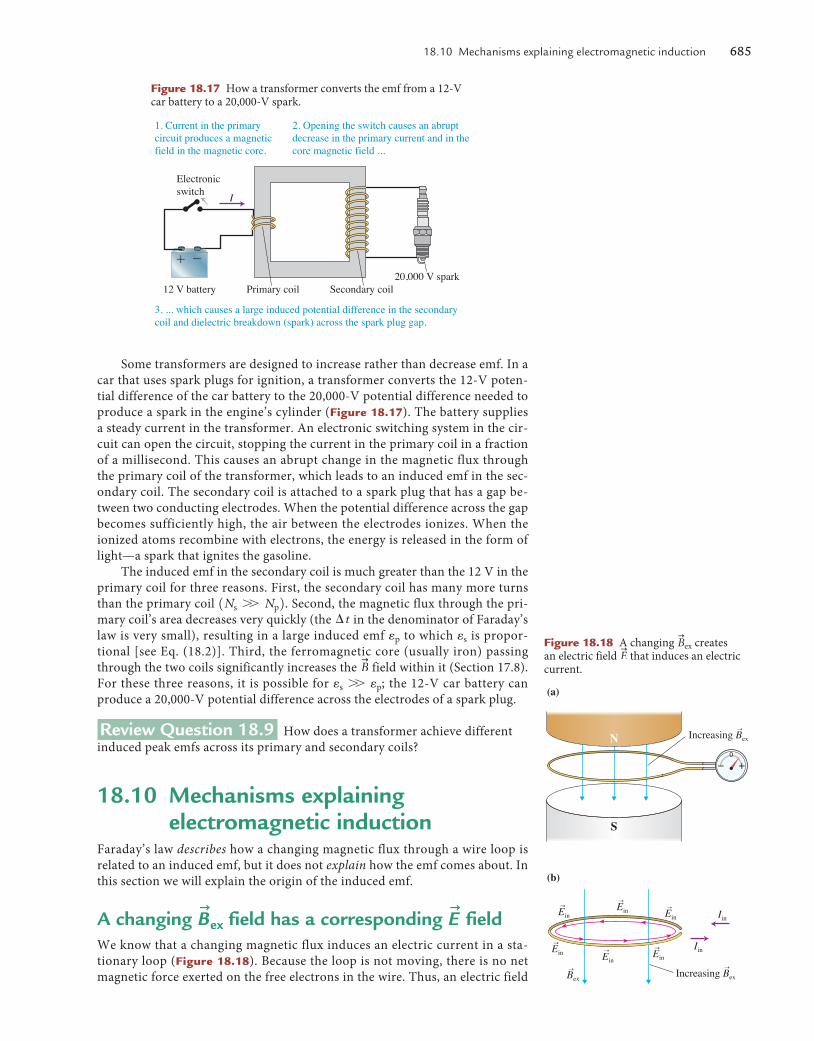
18.10 Mechanisms explaining electromagnetic induction 685
Some transformers are designed to increase rather than decrease emf. In a car that uses spark plugs for ignition, a transformer converts the 12-V poten-tial difference of the car battery to the 20,000-V potential difference needed to produce a spark in the engine’s cylinder (Figure 18.17). The battery supplies a steady current in the transformer. An electronic switching system in the cir-cuit can open the circuit, stopping the current in the primary coil in a fraction of a millisecond. This causes an abrupt change in the magnetic flux through the primary coil of the transformer, which leads to an induced emf in the sec-ondary coil. The secondary coil is attached to a spark plug that has a gap be-tween two conducting electrodes. When the potential difference across the gap becomes sufficiently high, the air between the electrodes ionizes. When the ionized atoms recombine with electrons, the energy is released in the form of light—a spark that ignites the gasoline.
The induced emf in the secondary coil is much greater than the 12 V in the primary coil for three reasons. First, the secondary coil has many more turns than the primary coil 1Ns W Np2. Second, the magnetic flux through the pri-mary coil’s area decreases very quickly (the �t in the denominator of Faraday’s law is very small), resulting in a large induced emf ep to which es is propor-tional [see Eq. (18.2)]. Third, the ferromagnetic core (usually iron) passing through the two coils significantly increases the
u
B field within it (Section 17.8). For these three reasons, it is possible for es W ep; the 12-V car battery can produce a 20,000-V potential difference across the electrodes of a spark plug.
Review Question 18.9 How does a transformer achieve different induced peak emfs across its primary and secondary coils?
18.10 Mechanisms explaining electromagnetic induction
Faraday’s law describes how a changing magnetic flux through a wire loop is related to an induced emf, but it does not explain how the emf comes about. In this section we will explain the origin of the induced emf.
A changing u
Bex field has a corresponding u
E fieldWe know that a changing magnetic flux induces an electric current in a sta-tionary loop (Figure 18.18). Because the loop is not moving, there is no net magnetic force exerted on the free electrons in the wire. Thus, an electric field
Figure 18.17 How a transformer converts the emf from a 12-V car battery to a 20,000-V spark.
12 V battery
Electronicswitch
Primary coil
I
Secondary coil
1. Current in the primarycircuit produces a magneticfield in the magnetic core.
2. Opening the switch causes an abrupt decrease in the primary current and in the core magnetic field ...
3. ... which causes a large induced potential difference in the secondary coil and dielectric breakdown (spark) across the spark plug gap.
20,000 V spark��
Figure 18.18 A changing u
Bex creates an electric field
u
E that induces an electric current.
Increasing Bexr
(a)
(b)
S
N
Increasing BexrrBex
rEin
rEin
rEin
rEin
rEin
rEinIin
Iin
M18_VANH5357_01_SE_C18.indd 685 19/07/13 10:19 AM
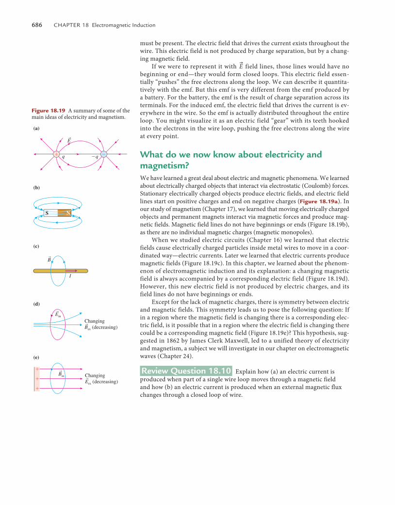
686 Chapter 18 electromagnetic Induction
Figure 18.19 A summary of some of the main ideas of electricity and magnetism.
ChangingBex (decreasing)
(a)
(b)
(c)
(d)
(e)
rB
r
ChangingEex (decreasing)r
rEin
rBin
NS
I
rE
must be present. The electric field that drives the current exists throughout the wire. This electric field is not produced by charge separation, but by a chang-ing magnetic field.
If we were to represent it with u
E field lines, those lines would have no beginning or end—they would form closed loops. This electric field essen-tially “pushes” the free electrons along the loop. We can describe it quantita-tively with the emf. But this emf is very different from the emf produced by a battery. For the battery, the emf is the result of charge separation across its terminals. For the induced emf, the electric field that drives the current is ev-erywhere in the wire. So the emf is actually distributed throughout the entire loop. You might visualize it as an electric field “gear” with its teeth hooked into the electrons in the wire loop, pushing the free electrons along the wire at every point.
What do we now know about electricity and magnetism?We have learned a great deal about electric and magnetic phenomena. We learned about electrically charged objects that interact via electrostatic (Coulomb) forces. Stationary electrically charged objects produce electric fields, and electric field lines start on positive charges and end on negative charges (Figure 18.19a). In our study of magnetism (Chapter 17), we learned that moving electrically charged objects and permanent magnets interact via magnetic forces and produce mag-netic fields. Magnetic field lines do not have beginnings or ends (Figure 18.19b), as there are no individual magnetic charges (magnetic monopoles).
When we studied electric circuits (Chapter 16) we learned that electric fields cause electrically charged particles inside metal wires to move in a coor-dinated way—electric currents. Later we learned that electric currents produce magnetic fields (Figure 18.19c). In this chapter, we learned about the phenom-enon of electromagnetic induction and its explanation: a changing magnetic field is always accompanied by a corresponding electric field (Figure 18.19d). However, this new electric field is not produced by electric charges, and its field lines do not have beginnings or ends.
Except for the lack of magnetic charges, there is symmetry between electric and magnetic fields. This symmetry leads us to pose the following question: If in a region where the magnetic field is changing there is a corresponding elec-tric field, is it possible that in a region where the electric field is changing there could be a corresponding magnetic field (Figure 18.19e)? This hypothesis, sug-gested in 1862 by James Clerk Maxwell, led to a unified theory of electricity and magnetism, a subject we will investigate in our chapter on electromagnetic waves (Chapter 24).
Review Question 18.10 Explain how (a) an electric current is produced when part of a single wire loop moves through a magnetic field and how (b) an electric current is produced when an external magnetic flux changes through a closed loop of wire.
M18_VANH5357_01_SE_C18.indd 686 19/07/13 10:19 AM
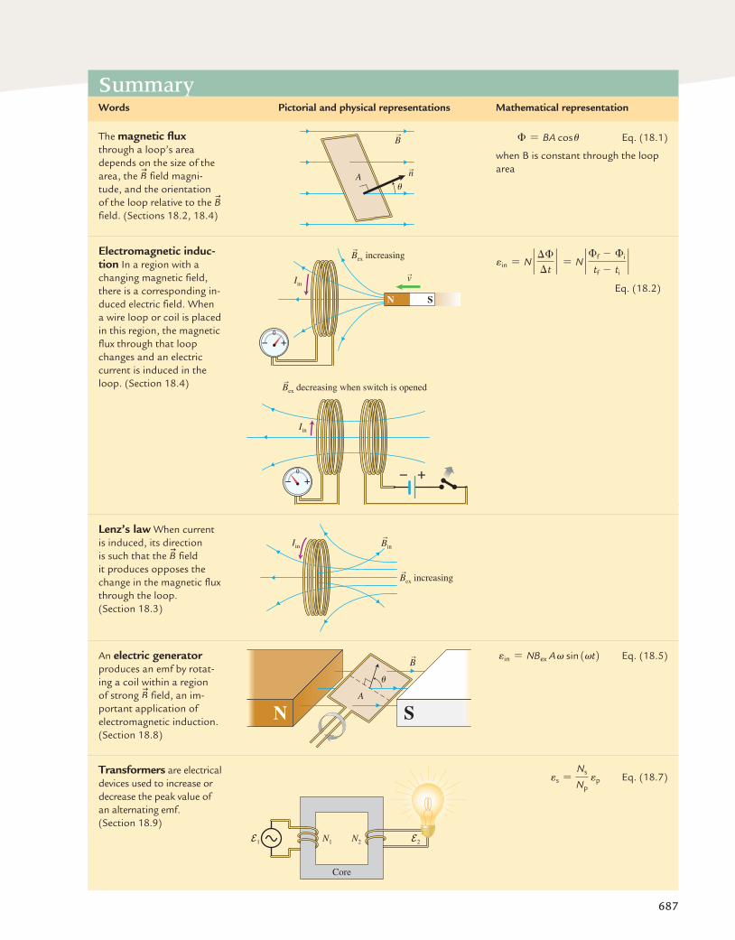
687
SummaryWords Pictorial and physical representations Mathematical representation
the magnetic flux through a loop’s area depends on the size of the area, the
u
B field magni-tude, and the orientation of the loop relative to the
u
B field. (Sections 18.2, 18.4)
rB
uA
rn
� = BA cos u eq. (18.1)
when B is constant through the loop area
Electromagnetic induc-tion In a region with a changing magnetic field, there is a corresponding in-duced electric field. When a wire loop or coil is placed in this region, the magnetic flux through that loop changes and an electric current is induced in the loop. (Section 18.4)
rv
N S
Iin
rBex increasing
Iin
rBex decreasing when switch is opened
ein = N ` ��
�t` = N ` �f - �i
tf - ti`
eq. (18.2)
Lenz’s law When current is induced, its direction is such that the
u
B field it produces opposes the change in the magnetic flux through the loop. (Section 18.3)
IinrBin
rBex increasing
an electric generator produces an emf by rotat-ing a coil within a region of strong
u
B field, an im-portant application of electromagnetic induction. (Section 18.8)
rB
A
u
N S
ein = NBex A v sin 1vt2 eq. (18.5)
Transformers are electrical devices used to increase or decrease the peak value of an alternating emf. (Section 18.9)
Core
N1E1 E2N2
es =Ns
Np ep eq. (18.7)
M18_VANH5357_01_SE_C18.indd 687 19/07/13 10:19 AM
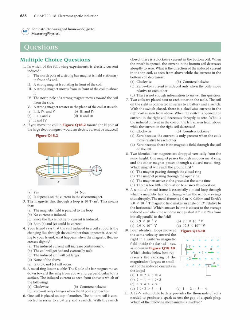
688 Chapter 18 electromagnetic Induction
Multiple Choice Questions 1. In which of the following experiments is electric current
induced?I. The north pole of a strong bar magnet is held stationary
in front of a coil.II. A strong magnet is rotating in front of the coil.III. A strong magnet moves from in front of the coil to above
it.IV. The north pole of a strong magnet moves toward the coil
from the side.V. A strong magnet rotates in the plane of the coil at its side.(a) I, II, IV, and V (b) III and IV(c) II, III, and V (d) II and III(e) II and IV
2. If you move the coil in Figure Q18.2 toward the N pole of the large electromagnet, would an electric current be induced?
a
b
S
NrB
(a) Yes (b) No(c) It depends on the current in the electromagnet.
3. The magnetic flux through a loop is 10 T # m2. This means that:(a) The magnetic field is parallel to the loop.(b) No current is induced.(c) Since the flux is not zero, current is induced.(d) Both (a) and (c) could be correct.
4. Your friend says that the emf induced in a coil supports the changing flux through the coil rather than opposes it. Accord-ing to your friend, what happens when the magnetic flux in-creases slightly?(a) The induced current will increase continuously.(b) The coil will get hot and eventually melt.(c) The induced emf will get larger.(d) None of the above.(e) (a), (b), and (c) will occur.
5. A metal ring lies on a table. The S pole of a bar magnet moves down toward the ring from above and perpendicular to its surface. The induced current as seen from above is which of the following?(a) Clockwise (b) Counterclockwise(c) Zero—it only changes when the N pole approaches
6. One coil is placed on top of another. The bottom coil is con-nected in series to a battery and a switch. With the switch
closed, there is a clockwise current in the bottom coil. When the switch is opened, the current in the bottom coil decreases abruptly to zero. What is the direction of the induced current in the top coil, as seen from above while the current in the bottom coil decreases?(a) Clockwise (b) Counterclockwise(c) Zero—the current is induced only when the coils move
relative to each other(d) There is not enough information to answer this question.
7. Two coils are placed next to each other on the table. The coil on the right is connected in series to a battery and a switch. With the switch closed, there is a clockwise current in the right coil as seen from above. When the switch is opened, the current in the right coil decreases abruptly to zero. What is the induced current in the coil on the left as seen from above while the current in the right coil decreases?(a) Clockwise (b) Counterclockwise(c) Zero because the current is only present when the coils
move relative to each other(d) Zero because there is no magnetic field through the coil
on the left 8. Two identical bar magnets are dropped vertically from the
same height. One magnet passes through an open metal ring, and the other magnet passes through a closed metal ring. Which magnet will reach the ground first?(a) The magnet passing through the closed ring(b) The magnet passing through the open ring(c) The magnets arrive at the ground at the same time.(d) There is too little information to answer this question.
9. A window’s metal frame is essentially a metal loop through which a magnetic field can change when the window swings shut abruptly. The metal frame is 1.0 m * 0.50 m and Earth’s 5.0 * 10- 5 T magnetic field makes an angle of 53� relative to the horizontal. Which answer below is closest to the average induced emf when the window swings shut 90� in 0.20 s from initially parallel to the field?(a) 9.9 * 10- 5 V (b) 7.5 * 10- 5 V(c) 9.9 * 10- 2 V (d) 12.5 * 10- 4 V
10. Four identical loops move at the same velocity toward the right in a uniform magnetic field inside the dashed lines, as shown in Figure Q18.10. Which choice below best rep-resents the ranking of the magnitudes (largest to small-est) of the induced currents in the loops?(a) 1 = 2 7 3 = 4(b) 2 = 1 = 4 7 3(c) 3 7 4 7 2 7 1(d) 1 7 2 7 3 = 4 (e) 1 = 2 = 3 = 4
11. A 12-V automobile battery provides the thousands of volts needed to produce a spark across the gap of a spark plug. Which of the following mechanisms is involved?
Questions
For instructor-assigned homework, go toMasteringPhysics.
Figure Q18.2
13
2
4rv
rvrv
rv
Figure Q18.10
M18_VANH5357_01_SE_C18.indd 688 19/07/13 10:19 AM
problems 689
(a) The secondary loop connected to the spark plug has many more turns than the primary loop attached to the battery.
(b) The current in the primary coil is reduced quickly.(c) An iron core increases the magnetic flux through the pri-
mary and secondary coils.(d) All three mechanisms are involved.(e) Only mechanisms (a) and (b) are involved.
12. A respiration detector consists of a coil placed on a person’s chest and another placed on the person’s back. There is a con-stant current in one coil. What causes an induced current to be produced in the other coil?(a) The person’s heart beats.(b) The person’s breathing causes the coil separation to change.(c) The person moves.(d) All three of the above occur.
13. A transformer has a small number of turns in the primary coil and a large number in the secondary. The electric power in-put to the primary coil is P = I�V. The secondary coil with more turns will have a greater emf (in volts) across it than the primary coil. If we connect the secondary coil across a light-bulb, we get which of the following?(a) Extra power because of the higher emf(b) The same power because of higher emf and lower current(c) Less power because the current is less(d) There is too little information to answer this question.
Conceptual Questions 14. A bar magnet falling with the north pole facing down passes
through a coil held vertically. Sketch flux-versus-time and emf-versus-time graphs for the magnet approaching the coil and passing through it. What assumptions did you make?
15. An induction cooktop has a smooth surface. When on high, the surface does not feel warm, yet it can quickly cook soup
in a metal bowl. However, it cannot cook soup in a ceramic or glass bowl. Explain how the cooktop works.
16. Use your knowledge of Lenz’s law to find the direction of the induced current in a coil when a magnet is falling through it. How many possible answers can you give?
17. Why does the magnetic field of the induced current oppose the change in the external magnetic field?
18. Describe three common applications of electromagnetic induction.
19. Two rectangular loops A and B are near each other. Loop A has a battery and a switch. Loop B has no battery. Imagine that a current starts increasing in loop A. Will there be a cur-rent in loop B? Samir argues that there will be current. Ariana argues that there will be no current. Provide experimental evi-dence to support the claims of both students.
20. An apnea monitor can prevent sudden infant death syndrome by sounding an alarm when a sleeping infant stops breathing. One coil carrying an alternating electric current is placed on the chest of an infant and a second coil is placed on the in-fant’s back. Explain how the apnea monitor detects the cessa-tion of breathing.
21. A simple metal detector has a coil with an alternating current in it. The current produces an alternating magnetic field. If a piece of metal is near the coil, eddy currents are induced in the metal. These induced eddy currents produce induced magnetic fields that are detected by a magnetic field detection device. Draw a series of sketches representing this process, including the appropriate directions of the magnetic fields at one instant of time, and indicate two applications for this device.
22. Construct flux-versus-time and emf-versus-time graphs that explain how an electric generator works.
23. How is it possible to get a 2000-V emf from a 12-volt battery?
Below, bIO indicates a problem with a biological or medical focus. problems labeled esT ask you to estimate the answer to a quantitative problem rather than derive a specific answer. prob-lems marked with require you to make a drawing or graph as part of your solution. asterisks indicate the level of difficulty of the problem. problems with no * are considered to be the least difficult. a single * marks moderately difficult problems. two ** indicate more difficult problems.
18.1 Inducing an electric current
1. * You and your friend are performing experiments in a phys-ics lab. Your friend claims that in general, something has to move in order to induce a current in a coil that has no bat-tery. What experiments can you perform to support her idea? What experiments can you perform to reject it?
2. * Your friend insists that a strong magnetic field is required to induce a current in a coil that has no battery. Describe one ex-periment that she and you can perform to observe that a strong magnetic field helps induce an electric current and two experi-ments where no current is induced even with a strong magnetic field. What should you conclude about your friend’s idea?
3. You decide to use a metal ring as an indicator of induced current. If there is a current, the ring will feel warm in your
hand. You place the ring around a solenoid, as shown in Figure p18.3. (a) Will the ring feel warm if there is constant nonzero current in the solenoid? (b) Will the ring feel warm if the current in the so-lenoid is alternating? Explain your answers.
4. * To check whether a lightbulb permanently attached to a coil is still good, you place the coil next to another coil that is at-tached to a battery, as shown in Figure p18.4. Explain how or whether each of the following actions can help you determine if the lightbulb is ok. (a) Close the switch in circuit A. (b) Keep the switch in circuit A closed. (c) Open the switch in circuit A.
5. * Flashlight without batteries A flashlight that operates without batteries is lying on your desk. The light illuminates only when you continuously squeeze the flashlight’s handle. You also notice that paper clips tend to stick to the outside
Problems
Figure p18.3
Figure p18.4
Loop A
Circuit A Loop B
ba
M18_VANH5357_01_SE_C18.indd 689 19/07/13 10:19 AM
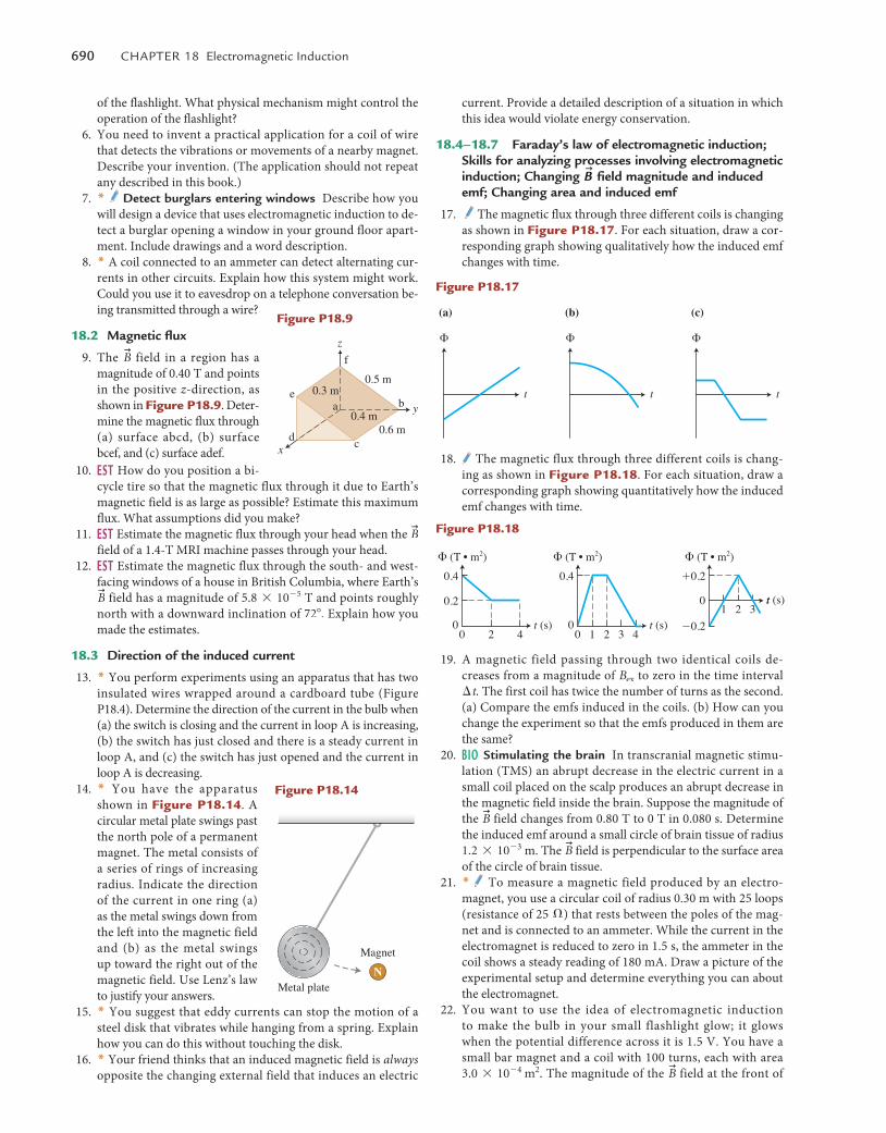
690 Chapter 18 electromagnetic Induction
current. Provide a detailed description of a situation in which this idea would violate energy conservation.
18.4–18.7 Faraday’s law of electromagnetic induction; Skills for analyzing processes involving electromagnetic induction; Changing
u
B field magnitude and induced emf; Changing area and induced emf
17. The magnetic flux through three different coils is changing as shown in Figure p18.17. For each situation, draw a cor-responding graph showing qualitatively how the induced emf changes with time.
(a) (b) (c)
�
t
�
t
�
t
18. The magnetic flux through three different coils is chang-ing as shown in Figure p18.18. For each situation, draw a corresponding graph showing quantitatively how the induced emf changes with time.
t (s)
t0.2
0.4 0.4
� (T • m2) � (T • m2) � (T • m2)
�0.2
�0.2
020 4
t (s)01 2 3
t (s)01 20 3 4
19. A magnetic field passing through two identical coils de-creases from a magnitude of Bex to zero in the time interval �t. The first coil has twice the number of turns as the second. (a) Compare the emfs induced in the coils. (b) How can you change the experiment so that the emfs produced in them are the same?
20. bIO Stimulating the brain In transcranial magnetic stimu-lation (TMS) an abrupt decrease in the electric current in a small coil placed on the scalp produces an abrupt decrease in the magnetic field inside the brain. Suppose the magnitude of the
u
B field changes from 0.80 T to 0 T in 0.080 s. Determine the induced emf around a small circle of brain tissue of radius 1.2 * 10- 3 m. The
u
B field is perpendicular to the surface area of the circle of brain tissue.
21. * To measure a magnetic field produced by an electro-magnet, you use a circular coil of radius 0.30 m with 25 loops (resistance of 25 �) that rests between the poles of the mag-net and is connected to an ammeter. While the current in the electromagnet is reduced to zero in 1.5 s, the ammeter in the coil shows a steady reading of 180 mA. Draw a picture of the experimental setup and determine everything you can about the electromagnet.
22. You want to use the idea of electromagnetic induction to make the bulb in your small flashlight glow; it glows when the potential difference across it is 1.5 V. You have a small bar magnet and a coil with 100 turns, each with area 3.0 * 10- 4 m2. The magnitude of the
u
B field at the front of
of the flashlight. What physical mechanism might control the operation of the flashlight?
6. You need to invent a practical application for a coil of wire that detects the vibrations or movements of a nearby magnet. Describe your invention. (The application should not repeat any described in this book.)
7. * detect burglars entering windows Describe how you will design a device that uses electromagnetic induction to de-tect a burglar opening a window in your ground floor apart-ment. Include drawings and a word description.
8. * A coil connected to an ammeter can detect alternating cur-rents in other circuits. Explain how this system might work. Could you use it to eavesdrop on a telephone conversation be-ing transmitted through a wire?
18.2 Magnetic flux
9. The u
B field in a region has a magnitude of 0.40 T and points in the positive z-direction, as shown in Figure p18.9. Deter-mine the magnetic flux through (a) surface abcd, (b) surface bcef, and (c) surface adef.
10. esT How do you position a bi-cycle tire so that the magnetic flux through it due to Earth’s magnetic field is as large as possible? Estimate this maximum flux. What assumptions did you make?
11. esT Estimate the magnetic flux through your head when the u
B field of a 1.4-T MRI machine passes through your head.
12. esT Estimate the magnetic flux through the south- and west-facing windows of a house in British Columbia, where Earth’s u
B field has a magnitude of 5.8 * 10- 5 T and points roughly north with a downward inclination of 72�. Explain how you made the estimates.
18.3 direction of the induced current
13. * You perform experiments using an apparatus that has two insulated wires wrapped around a cardboard tube (Figure P18.4). Determine the direction of the current in the bulb when (a) the switch is closing and the current in loop A is increasing, (b) the switch has just closed and there is a steady current in loop A, and (c) the switch has just opened and the current in loop A is decreasing.
14. * You have the apparatus shown in Figure p18.14. A circular metal plate swings past the north pole of a permanent magnet. The metal consists of a series of rings of increasing radius. Indicate the direction of the current in one ring (a) as the metal swings down from the left into the magnetic field and (b) as the metal swings up toward the right out of the magnetic field. Use Lenz’s law to justify your answers.
15. * You suggest that eddy currents can stop the motion of a steel disk that vibrates while hanging from a spring. Explain how you can do this without touching the disk.
16. * Your friend thinks that an induced magnetic field is always opposite the changing external field that induces an electric
x
z
f
a b
cd
e0.5 m
0.4 m0.6 m
0.3 m
y
Figure p18.9
Figure p18.14
Metal plate
Magnet
N
Figure p18.17
Figure p18.18
M18_VANH5357_01_SE_C18.indd 690 19/07/13 10:19 AM
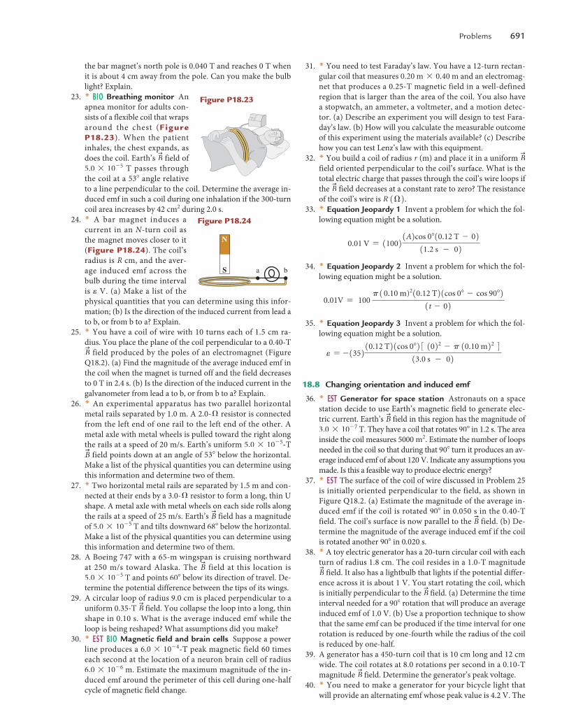
problems 691
31. * You need to test Faraday’s law. You have a 12-turn rectan-gular coil that measures 0.20 m * 0.40 m and an electromag-net that produces a 0.25-T magnetic field in a well-defined region that is larger than the area of the coil. You also have a stopwatch, an ammeter, a voltmeter, and a motion detec-tor. (a) Describe an experiment you will design to test Fara-day’s law. (b) How will you calculate the measurable outcome of this experiment using the materials available? (c) Describe how you can test Lenz’s law with this equipment.
32. * You build a coil of radius r (m) and place it in a uniform u
B field oriented perpendicular to the coil’s surface. What is the total electric charge that passes through the coil’s wire loops if the
u
B field decreases at a constant rate to zero? The resistance of the coil’s wire is R 1�2.
33. * Equation Jeopardy 1 Invent a problem for which the fol-lowing equation might be a solution.
0.01 V = 110021A2cos 0�10.12 T - 0211.2 s - 02
34. * Equation Jeopardy 2 Invent a problem for which the fol-lowing equation might be a solution.
0.01V = 100 p10.10 m)210.12 T21cos 0� - cos 90�2
1t - 02 35. * Equation Jeopardy 3 Invent a problem for which the fol-
lowing equation might be a solution.
e = -135210.12 T21cos 0�23 1022 - p 10.10 m22 413.0 s - 02
18.8 Changing orientation and induced emf
36. * esT Generator for space station Astronauts on a space station decide to use Earth’s magnetic field to generate elec-tric current. Earth’s
u
B field in this region has the magnitude of 3.0 * 10- 7 T. They have a coil that rotates 90� in 1.2 s. The area inside the coil measures 5000 m2. Estimate the number of loops needed in the coil so that during that 90� turn it produces an av-erage induced emf of about 120 V. Indicate any assumptions you made. Is this a feasible way to produce electric energy?
37. * esT The surface of the coil of wire discussed in Problem 25 is initially oriented perpendicular to the field, as shown in Figure Q18.2. (a) Estimate the magnitude of the average in-duced emf if the coil is rotated 90� in 0.050 s in the 0.40-T field. The coil’s surface is now parallel to the
u
B field. (b) De-termine the magnitude of the average induced emf if the coil is rotated another 90� in 0.020 s.
38. * A toy electric generator has a 20-turn circular coil with each turn of radius 1.8 cm. The coil resides in a 1.0-T magnitude u
B field. It also has a lightbulb that lights if the potential differ-ence across it is about 1 V. You start rotating the coil, which is initially perpendicular to the
u
B field. (a) Determine the time interval needed for a 90� rotation that will produce an average induced emf of 1.0 V. (b) Use a proportion technique to show that the same emf can be produced if the time interval for one rotation is reduced by one-fourth while the radius of the coil is reduced by one-half.
39. A generator has a 450-turn coil that is 10 cm long and 12 cm wide. The coil rotates at 8.0 rotations per second in a 0.10-T magnitude
u
B field. Determine the generator’s peak voltage. 40. * You need to make a generator for your bicycle light that
will provide an alternating emf whose peak value is 4.2 V. The
the bar magnet’s north pole is 0.040 T and reaches 0 T when it is about 4 cm away from the pole. Can you make the bulb light? Explain.
23. * bIO Breathing monitor An apnea monitor for adults con-sists of a flexible coil that wraps around the chest (Figure p18.23). When the patient inhales, the chest expands, as does the coil. Earth’s
u
B field of 5.0 * 10- 5 T passes through the coil at a 53� angle relative to a line perpendicular to the coil. Determine the average in-duced emf in such a coil during one inhalation if the 300-turn coil area increases by 42 cm2 during 2.0 s.
24. * A bar magnet induces a current in an N-turn coil as the magnet moves closer to it (Figure p18.24). The coil’s radius is R cm, and the aver-age induced emf across the bulb during the time interval is e V. (a) Make a list of the physical quantities that you can determine using this infor-mation; (b) Is the direction of the induced current from lead a to b, or from b to a? Explain.
25. * You have a coil of wire with 10 turns each of 1.5 cm ra-dius. You place the plane of the coil perpendicular to a 0.40-T u
B field produced by the poles of an electromagnet (Figure Q18.2). (a) Find the magnitude of the average induced emf in the coil when the magnet is turned off and the field decreases to 0 T in 2.4 s. (b) Is the direction of the induced current in the galvanometer from lead a to b, or from b to a? Explain.
26. * An experimental apparatus has two parallel horizontal metal rails separated by 1.0 m. A 2.0-� resistor is connected from the left end of one rail to the left end of the other. A metal axle with metal wheels is pulled toward the right along the rails at a speed of 20 m/s. Earth’s uniform 5.0 * 10- 5-T u
B field points down at an angle of 53� below the horizontal. Make a list of the physical quantities you can determine using this information and determine two of them.
27. * Two horizontal metal rails are separated by 1.5 m and con-nected at their ends by a 3.0-� resistor to form a long, thin U shape. A metal axle with metal wheels on each side rolls along the rails at a speed of 25 m/s. Earth’s
u
B field has a magnitude of 5.0 * 10- 5 T and tilts downward 68� below the horizontal. Make a list of the physical quantities you can determine using this information and determine two of them.
28. A Boeing 747 with a 65-m wingspan is cruising northward at 250 m/s toward Alaska. The
u
B field at this location is 5.0 * 10- 5 T and points 60� below its direction of travel. De-termine the potential difference between the tips of its wings.
29. A circular loop of radius 9.0 cm is placed perpendicular to a uniform 0.35-T
u
B field. You collapse the loop into a long, thin shape in 0.10 s. What is the average induced emf while the loop is being reshaped? What assumptions did you make?
30. * esT bIO Magnetic field and brain cells Suppose a power line produces a 6.0 * 10- 4-T peak magnetic field 60 times each second at the location of a neuron brain cell of radius 6.0 * 10- 6 m. Estimate the maximum magnitude of the in-duced emf around the perimeter of this cell during one-half cycle of magnetic field change.
Figure p18.23
N
S a b
Figure p18.24
M18_VANH5357_01_SE_C18.indd 691 19/07/13 10:19 AM
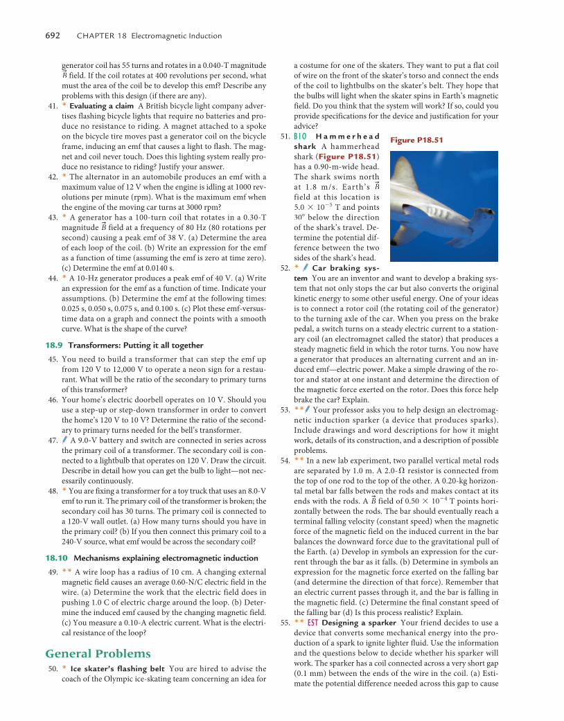
692 Chapter 18 electromagnetic Induction
a costume for one of the skaters. They want to put a flat coil of wire on the front of the skater’s torso and connect the ends of the coil to lightbulbs on the skater’s belt. They hope that the bulbs will light when the skater spins in Earth’s magnetic field. Do you think that the system will work? If so, could you provide specifications for the device and justification for your advice?
51. b I O H a m m e r h e a d shark A hammerhead shark (Figure p18.51) has a 0.90-m-wide head. The shark swims north at 1.8 m/s. Earth’s
u
B field at this location is 5.0 * 10- 5 T and points 30� below the direction of the shark’s travel. De-termine the potential dif-ference between the two sides of the shark’s head.
52. * Car braking sys-tem You are an inventor and want to develop a braking sys-tem that not only stops the car but also converts the original kinetic energy to some other useful energy. One of your ideas is to connect a rotor coil (the rotating coil of the generator) to the turning axle of the car. When you press on the brake pedal, a switch turns on a steady electric current to a station-ary coil (an electromagnet called the stator) that produces a steady magnetic field in which the rotor turns. You now have a generator that produces an alternating current and an in-duced emf—electric power. Make a simple drawing of the ro-tor and stator at one instant and determine the direction of the magnetic force exerted on the rotor. Does this force help brake the car? Explain.
53. ** Your professor asks you to help design an electromag-netic induction sparker (a device that produces sparks). Include drawings and word descriptions for how it might work, details of its construction, and a description of possible problems.
54. ** In a new lab experiment, two parallel vertical metal rods are separated by 1.0 m. A 2.0-� resistor is connected from the top of one rod to the top of the other. A 0.20-kg horizon-tal metal bar falls between the rods and makes contact at its ends with the rods. A
u
B field of 0.50 * 10- 4 T points hori-zontally between the rods. The bar should eventually reach a terminal falling velocity (constant speed) when the magnetic force of the magnetic field on the induced current in the bar balances the downward force due to the gravitational pull of the Earth. (a) Develop in symbols an expression for the cur-rent through the bar as it falls. (b) Determine in symbols an expression for the magnetic force exerted on the falling bar (and determine the direction of that force). Remember that an electric current passes through it, and the bar is falling in the magnetic field. (c) Determine the final constant speed of the falling bar (d) Is this process realistic? Explain.
55. ** esT designing a sparker Your friend decides to use a device that converts some mechanical energy into the pro-duction of a spark to ignite lighter fluid. Use the information and the questions below to decide whether his sparker will work. The sparker has a coil connected across a very short gap (0.1 mm) between the ends of the wire in the coil. (a) Esti-mate the potential difference needed across this gap to cause
generator coil has 55 turns and rotates in a 0.040-T magnitude u
B field. If the coil rotates at 400 revolutions per second, what must the area of the coil be to develop this emf? Describe any problems with this design (if there are any).
41. * Evaluating a claim A British bicycle light company adver-tises flashing bicycle lights that require no batteries and pro-duce no resistance to riding. A magnet attached to a spoke on the bicycle tire moves past a generator coil on the bicycle frame, inducing an emf that causes a light to flash. The mag-net and coil never touch. Does this lighting system really pro-duce no resistance to riding? Justify your answer.
42. * The alternator in an automobile produces an emf with a maximum value of 12 V when the engine is idling at 1000 rev-olutions per minute (rpm). What is the maximum emf when the engine of the moving car turns at 3000 rpm?
43. * A generator has a 100-turn coil that rotates in a 0.30-T magnitude
u
B field at a frequency of 80 Hz (80 rotations per second) causing a peak emf of 38 V. (a) Determine the area of each loop of the coil. (b) Write an expression for the emf as a function of time (assuming the emf is zero at time zero). (c) Determine the emf at 0.0140 s.
44. * A 10-Hz generator produces a peak emf of 40 V. (a) Write an expression for the emf as a function of time. Indicate your assumptions. (b) Determine the emf at the following times: 0.025 s, 0.050 s, 0.075 s, and 0.100 s. (c) Plot these emf-versus-time data on a graph and connect the points with a smooth curve. What is the shape of the curve?
18.9 Transformers: Putting it all together
45. You need to build a transformer that can step the emf up from 120 V to 12,000 V to operate a neon sign for a restau-rant. What will be the ratio of the secondary to primary turns of this transformer?
46. Your home’s electric doorbell operates on 10 V. Should you use a step-up or step-down transformer in order to convert the home’s 120 V to 10 V? Determine the ratio of the second-ary to primary turns needed for the bell’s transformer.
47. A 9.0-V battery and switch are connected in series across the primary coil of a transformer. The secondary coil is con-nected to a lightbulb that operates on 120 V. Draw the circuit. Describe in detail how you can get the bulb to light—not nec-essarily continuously.
48. * You are fixing a transformer for a toy truck that uses an 8.0-V emf to run it. The primary coil of the transformer is broken; the secondary coil has 30 turns. The primary coil is connected to a 120-V wall outlet. (a) How many turns should you have in the primary coil? (b) If you then connect this primary coil to a 240-V source, what emf would be across the secondary coil?
18.10 Mechanisms explaining electromagnetic induction
49. ** A wire loop has a radius of 10 cm. A changing external magnetic field causes an average 0.60-N/C electric field in the wire. (a) Determine the work that the electric field does in pushing 1.0 C of electric charge around the loop. (b) Deter-mine the induced emf caused by the changing magnetic field. (c) You measure a 0.10-A electric current. What is the electri-cal resistance of the loop?
General Problems 50. * Ice skater’s flashing belt You are hired to advise the
coach of the Olympic ice-skating team concerning an idea for
Figure p18.51
M18_VANH5357_01_SE_C18.indd 692 19/07/13 10:19 AM
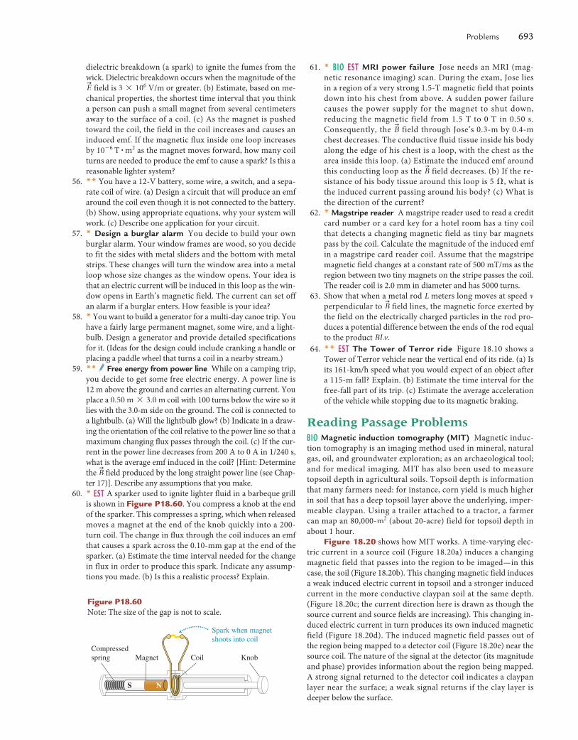
problems 693
61. * b I O e s T MRI power failure Jose needs an MRI (mag-netic resonance imaging) scan. During the exam, Jose lies in a region of a very strong 1.5-T magnetic field that points down into his chest from above. A sudden power failure causes the power supply for the magnet to shut down, reducing the magnetic field from 1.5 T to 0 T in 0.50 s. Consequently, the
u
B field through Jose’s 0.3-m by 0.4-m chest decreases. The conductive fluid tissue inside his body along the edge of his chest is a loop, with the chest as the area inside this loop. (a) Estimate the induced emf around this conducting loop as the
u
B field decreases. (b) If the re-sistance of his body tissue around this loop is 5 �, what is the induced current passing around his body? (c) What is the direction of the current?
62. * Magstripe reader A magstripe reader used to read a credit card number or a card key for a hotel room has a tiny coil that detects a changing magnetic field as tiny bar magnets pass by the coil. Calculate the magnitude of the induced emf in a magstripe card reader coil. Assume that the magstripe magnetic field changes at a constant rate of 500 mT/ms as the region between two tiny magnets on the stripe passes the coil. The reader coil is 2.0 mm in diameter and has 5000 turns.
63. Show that when a metal rod L meters long moves at speed v perpendicular to
u
B field lines, the magnetic force exerted by the field on the electrically charged particles in the rod pro-duces a potential difference between the ends of the rod equal to the product BLv.
64. ** esT The Tower of Terror ride Figure 18.10 shows a Tower of Terror vehicle near the vertical end of its ride. (a) Is its 161-km/h speed what you would expect of an object after a 115-m fall? Explain. (b) Estimate the time interval for the free-fall part of its trip. (c) Estimate the average acceleration of the vehicle while stopping due to its magnetic braking.
Reading Passage ProblemsbIO Magnetic induction tomography (MIT) Magnetic induc-tion tomography is an imaging method used in mineral, natural gas, oil, and groundwater exploration; as an archaeological tool; and for medical imaging. MIT has also been used to measure topsoil depth in agricultural soils. Topsoil depth is information that many farmers need: for instance, corn yield is much higher in soil that has a deep topsoil layer above the underlying, imper-meable claypan. Using a trailer attached to a tractor, a farmer can map an 80,000-m2 (about 20-acre) field for topsoil depth in about 1 hour.
Figure 18.20 shows how MIT works. A time-varying elec-tric current in a source coil (Figure 18.20a) induces a changing magnetic field that passes into the region to be imaged—in this case, the soil (Figure 18.20b). This changing magnetic field induces a weak induced electric current in topsoil and a stronger induced current in the more conductive claypan soil at the same depth. (Figure 18.20c; the current direction here is drawn as though the source current and source fields are increasing). This changing in-duced electric current in turn produces its own induced magnetic field (Figure 18.20d). The induced magnetic field passes out of the region being mapped to a detector coil (Figure 18.20e) near the source coil. The nature of the signal at the detector (its magnitude and phase) provides information about the region being mapped. A strong signal returned to the detector coil indicates a claypan layer near the surface; a weak signal returns if the clay layer is deeper below the surface.
dielectric breakdown (a spark) to ignite the fumes from the wick. Dielectric breakdown occurs when the magnitude of the u
E field is 3 * 106 V/m or greater. (b) Estimate, based on me-chanical properties, the shortest time interval that you think a person can push a small magnet from several centimeters away to the surface of a coil. (c) As the magnet is pushed toward the coil, the field in the coil increases and causes an induced emf. If the magnetic flux inside one loop increases by 10- 6 T # m2 as the magnet moves forward, how many coil turns are needed to produce the emf to cause a spark? Is this a reasonable lighter system?
56. ** You have a 12-V battery, some wire, a switch, and a sepa-rate coil of wire. (a) Design a circuit that will produce an emf around the coil even though it is not connected to the battery. (b) Show, using appropriate equations, why your system will work. (c) Describe one application for your circuit.
57. * design a burglar alarm You decide to build your own burglar alarm. Your window frames are wood, so you decide to fit the sides with metal sliders and the bottom with metal strips. These changes will turn the window area into a metal loop whose size changes as the window opens. Your idea is that an electric current will be induced in this loop as the win-dow opens in Earth’s magnetic field. The current can set off an alarm if a burglar enters. How feasible is your idea?
58. * You want to build a generator for a multi-day canoe trip. You have a fairly large permanent magnet, some wire, and a light-bulb. Design a generator and provide detailed specifications for it. (Ideas for the design could include cranking a handle or placing a paddle wheel that turns a coil in a nearby stream.)
59. ** Free energy from power line While on a camping trip, you decide to get some free electric energy. A power line is 12 m above the ground and carries an alternating current. You place a 0.50 m * 3.0 m coil with 100 turns below the wire so it lies with the 3.0-m side on the ground. The coil is connected to a lightbulb. (a) Will the lightbulb glow? (b) Indicate in a draw-ing the orientation of the coil relative to the power line so that a maximum changing flux passes through the coil. (c) If the cur-rent in the power line decreases from 200 A to 0 A in 1/240 s, what is the average emf induced in the coil? [Hint: Determine the
u
B field produced by the long straight power line (see Chap-ter 17)]. Describe any assumptions that you make.
60. * esT A sparker used to ignite lighter fluid in a barbeque grill is shown in Figure p18.60. You compress a knob at the end of the sparker. This compresses a spring, which when released moves a magnet at the end of the knob quickly into a 200-turn coil. The change in flux through the coil induces an emf that causes a spark across the 0.10-mm gap at the end of the sparker. (a) Estimate the time interval needed for the change in flux in order to produce this spark. Indicate any assump-tions you made. (b) Is this a realistic process? Explain.
Figure p18.60 Note: The size of the gap is not to scale.
Spark when magnetshoots into coil
KnobMagnet CoilCompressedspring
NS
M18_VANH5357_01_SE_C18.indd 693 19/07/13 10:19 AM
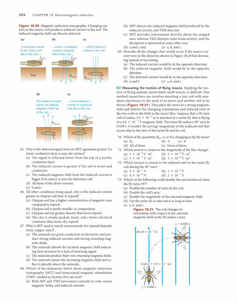
694 Chapter 18 electromagnetic Induction
(b) MIT detects the induced magnetic field produced by the induced current, and TMS does not.
(c) MIT provides information directly about the imaged area, whereas TMS disrupts some brain activity, and the disruption is measured in some other way.
(d) a and c only (e) a, b, and c 69. Describe all the changes that would occur if the source cur-
rent were in the direction shown in Figure 18.20 but decreas-ing instead of increasing.(a) The induced current would be in the opposite direction.(b) The induced magnetic field would be in the opposite
direction.(c) The detected current would be in the opposite direction. (d) a and b (e) a, b, and c
bIO Measuring the motion of flying insects Studying the mo-tion of flying animals, particularly small insects, is difficult. One method researchers use involves attaching a tiny coil with min-iature electronics to the neck of an insect and another coil to its thorax (Figure 18.21). They place the insect in a strong magnetic field and observe the changing orientations and induced emfs of the two coils in the field as the insect flies. Suppose that a 50-turn coil of radius 2.0 * 10- 3 m is attached to a tsetse fly that is flying in a 4.0 * 10- 3-T magnetic field. The tsetse fly makes a 90� turn in 0.020 s. Consider the average magnitude of the induced emf that occurs due to the turn of the tsetse fly and its coil.
70. Which of the quantities Bex, A, or u is changing as the fly turns?(a) Bex (b) A (c) u(d) All of them (e) None of them
71. Which answer is closest to the magnitude of the flux change?(a) 1 * 10- 4 T # m2 (b) 2 * 10- 6 T # m2
(c) 3 * 10- 7 T # m2 (d) 5 * 10- 8 T # m2
72. Which answer is closest to the induced emf on the tsetse fly coil during the 90� turn?(a) 6 * 10- 2 V (b) 1 * 10 -4 V(c) 4 * 10- 6 V (d) 2 * 10- 7 V
73. Which of the following could double the emf produced when the fly turns 90�?(a) Double the number of turns in the coil.(b) Double the coil’s area.(c) Double the magnitude of the external magnetic field.(d) Get the tsetse fly to take twice as long to turn.(e) a, b, and c
65. Why is the detected signal from an MIT apparatus greater if a moist conductive layer is near the surface?(a) The signal is reflected better from the top of a nearby
conductive layer.(b) The induced current is greater if the soil is moist and
conductive.(c) The induced magnetic field from the induced current is
bigger if its source is near the detection coil.(d) All three of the above reasons(e) b and c
66. All other conditions being equal, why is the induced current greater in claypan soil than in topsoil?(a) Claypan soil has a higher concentration of magnetic ions
compared to topsoil.(b) Claypan soil is partly metallic in composition.(c) Claypan soil has greater density than loose topsoil. (d) The clay is closely packed, moist, and a better electrical
conductor than loose, dry topsoil. 67. Why is MIT used to search noninvasively for mineral deposits
(iron, copper, zinc)?(a) The minerals are good conductors of electricity and pro-
duce strong induced currents and strong returning mag-netic fields.
(b) The minerals absorb the incident magnetic field indicat-ing their presence by a lack of returning signal.
(c) The minerals produce their own returning magnetic fields.(d) The minerals attract the incoming magnetic field and re-
flect it directly above the minerals. 68. Which of the statements below about magnetic induction
tomography (MIT) and transcranial magnetic stimulation (TMS), studied in Section 18.6, are true?(a) Both MIT and TMS have source currents in coils, source
magnetic fields, and induced currents.
Coil (r � 2.0 � 10�3 m)
ti � 0.000 s
tf � 0.020 s
B (4.0 � 10�3 T)r
Figure 18.21 The coil changes its orientation with respect to the external magnetic field as the fly makes a turn.
Figure 18.20 Magnetic induction tomography. Changing cur-rent in the source coil produces induced current in the soil. The induced magnetic field can then be detected.
Soil
(a)
A changing current in the source coil above the soil ...
(b)
... causes a changing external magnetic field in the soil ...
Isource Isource
Idetector
Bsource Bsource
(c)
... which induces a current in the soil.
Iin
(d)
The induced currentcauses an inducedmagnetic field out of the soil ...
Binduced
Bin
(e)
... which induces a current in a detectorcoil above the soil.
Iin
M18_VANH5357_01_SE_C18.indd 694 19/07/13 10:19 AM