electromagnetic interference shielding effectiveness of · electromagnetic interference shielding...
TRANSCRIPT
Electromagnetic Interference Shielding Effect of Nanocomposites with
Carbon Nanotube and Shape Memory Polymer
Chun-Sheng Zhang a, Qing-Qing Ni* b, Shao-Yun Fu c, and Ken Kurashiki a
a Division of Advance Fibro-Science, Kyoto Institute of Technology
Matsugasaki sakyo-ku, Kyoto 606-8585, Japan
b Dept of Functional Machinery and Mechanics, Shinshu University
3-15-1 Tokida, Ueda 386-8567, Japan
c Technical Institute of Physics and Chemistry, Chinese Academy of Sciences (CAS)
Zhongguancun, Beijing 100080, China
* Corresponding author
Prof. Qing-Qing Ni
Dept of Functional Machinery and Mechanics, Shinshu University
3-15-1 Tokida, Ueda 386-8567, Japan
E-mail: [email protected]
Fax: +0081-268-215438
Tel: +0081-268-215438
Abstract
The nanocomposites with carbon nanotubes (CNTs) and shape memory polymer (SMP) were
developed for electrical applications. The specimens with different CNTs weight fractions were
prepared. Their electrical resistivities and electromagnetic interference (EMI) shielding
effectiveness (SE) were investigated. The electrical resistivity was examined by four-probe method
at different testing temperatures of 25, 35, 45, 55 and 65 ˚C around glass transfer temperature (Tg).
As a result, for the developed nanocomposites, even lower weight fraction of CNTs could achieve a
high level of conductivity and a low percolation threshold for CNTs content was confirmed. The
electrical resistivity for the developed nanocomposites is dependant obviously on temperature with
a linear relation like metals. The interconnected conducting network was formed more easily than
other fillers. For the EMI SE measurements, a near-field antenna measurement system was used.
The experiments to evaluate EMI SE were carried out in three different frequency bands, 8~26.5
GHz (K band), 33~50 GHz (Q band) and 50~75 GHz (V band). The EMI SE of CNT/SMP
nanocomposites have a strong dependence of carbon nanotube content and the specimen thickness
at all of three frequency bands. The higher frequency, the larger EMI SE. For the materials with
5.5wt% VGCFs both experiment and analysis will agree well, and theoretical prediction proposed
for EMI SE may be useful.
Key word: Carbon nanotube, Shape memory polymer, Electrical resistivity,
Electromagnetic interference (EMI), Shielding effectiveness (SE)
1
1. Introduction
In recent years, the progress of technology and increment in the amount of information are
remarkable and high-speed communication is indispensable. To realize high-speed communication,
the higher frequency range from the microwave to the millimeter wave is expected. Many electronic
instruments with the higher frequency, such as satellite communication, automobile collision
prevention radar, accident surveillance of a railroad, and millimeter wave wireless LAN and so on,
have been developed and applied [1,2]. The electromagnetic waves produced from some electronic
instruments have an adverse effect on the performance to other equipments. This is called as
electromagnetic interference (EMI). EMI may cause malfunction to medical apparatus, industry
robots or even cause harm to human body and become one of public nuisances [3-6]. Therefore, in
order to alleviate these troubles the development of EMI shielding materials for microwave and
millimeter waves are receiving increasing attention briskly.
EMI shielding refers to the reflection and/or adsorption of electromagnetic radiation by a
material, which thereby acts as a shield against the penetration of the radiation through it [7]. The
shield should be in high conductance, thus metals, such as steel, copper, aluminum, etc., are the
most common materials used for EMI shielding. Since metal shielding has shortcomings of heavy
weight, corrosion and physical rigidity, polymer composites with discontinuous conducting fillers,
such as metal particles, carbon particles, carbon fiber, are extensively employed in EMI shielding
[8-13]. Although these composites are not strong enough for most structural applications, they are
attractive because of their superior molding and more dependable lightweight. For these composites,
the EMI shielding effectiveness increases with increasing fraction of the filler and with increasing
aspect ratio of the filler. The aspect ratio is defined as the ratio of the length to the diameter of the
conductive fillers. According to the electromagnetic wave percolation theory, if the conductive filler
in a polymer composite retains a high aspect ratio, the filler easily forms a conductive network. At a
2
certain threshold value of fraction of the filler, the particles or fibers are sufficiently close-packed to
form unbroken conducting pathway through the composite, and the conductivity of the material
increases sharply [10, 14].
Among the various conductive fillers, carbon nanotubes (CNTs) have been shown to be an
excellent candidate for EMI shielding due to higher aspect ratio and large surface area [14]. Vapor
grown carbon nanofibers (VGCFs), referred as multiwall carbon nanotubes (CNTs), typically have
diameters in the range of 50–200 nm. Compared with other CNTs, VGCFs can be produced today
in a large amount and at lower cost by using natural gas or coal as a stock catalyst [15, 16]. Their
good thermal and electrical conductivity, excellent mechanical properties, high aspect ratio (up to
1000) and low cost have attracted attention from both industrial and academic sides [17-19].
Many researches on the enhanced thermal, mechanical and electrical properties and EMI shield
effect for VGCF base composites were conducted [15, 20-28]. However, the study on the unique
nanocomposite with carbon nanotubes and shape memory polymer (SMP) is just on the way. The
authors have reported the characteristics of shape memory effect on CNT/SMP nanocomposites in
previous paper [29], where their electromagnetic interference (EMI) shielding effectiveness (SE)
has not been investigated.
Shape memory polymer (SMP) has the characteristics such as large recoverability, lightweight,
superior molding property and so on. These advantages have resulted in that the SMPs become one
of functional materials from many fields [30-32]. For SMP of polyurethane series, its glass transfer
temperature (Tg) may be set up around room temperature, and it has a large difference in
mechanical properties, optical characteristics and steam permeability above and below the
temperature Tg. The characterizations such as shape recovery and/or shape fixation may appear to
be quite different. Thus the polyurethane SMP will have wider applications in the field of industry,
medical treatment, welfare and daily life as an actuation material [33-36]. A significant property of
3
SMP materials is their low stiffness. A few researchers have studied composite material based on a
shape memory polymer matrix [37-39]. In our previous paper [29], carbon nanotube reinforced
shape memory, CNT/SMP, nanocomposites were developed. The investigated results showed when
a plate was made no matter how complicated shape was requested in the practical use, it could be
obtained by heating and then molding the plate to a required one after cooling due to the shape
stability of SMP. Moreover, any structure and its thickness in a product can be designed and
controlled by laminating technology. Therefore, CNT/SMP nanocomposites provided that there
exists sufficient intrinsic EMI shielding capability may be hopeful for electrical and electronic
applications. Here, the electromagnetic interference (EMI) shielding effectiveness (SE) for the
developed CNT/SMP nanocomposites are investigated and their electrical resistivities and the
relationship between the electrical resistivity and temperature were examined. And EMI SE values
for CNT/SMP nanocomposites with different thicknesses were compared.
2. Experimental Work
2.1. Materials
Multi wall carbon nanotubes (VGCFs) produced by Showa Denko K.K. were used with an
average diameter of about 150 nm and the length of 10~20 µm. The polyesterpolyol series of
polyurethane shape memory polymer were used as a matrix and its glass transition temperature Tg is
about 45 ˚C. The raw material is liquid and the weight ratio of polymer to solvent is set to be 3:7.
2.2. Fabrication of Specimens
Carbon nanotubes were put into a solvent little by little and dispersed for 3 h at 45 ˚C by
ultrasonic vibration with oscillation frequency of 42 kHz and the power of 125 W. The diluted SMP
solution is gradually poured into the mixed solution of VGCFs and solvent, and then the mixture
was dispersed for 3 hours. Then the mixture was cast into a container and dried at 70 ˚C, and the
4
CNT/SMP nanocomposites were prepared. In order to vaporize water completely, CNT/SMP
nanocomposites were dried at 110 ˚C. The weight fraction of VGCFs was 1.7, 3.3, 5.0 and 6.7 wt%,
respectively. For comparison, the pure SMP films were also prepared in a similar method. The
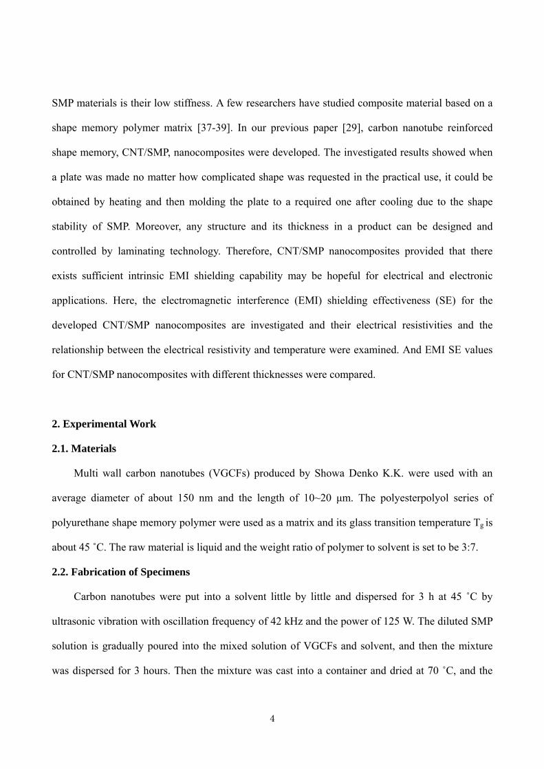
developed CNT/SMP nanocomposites were examined in a scanning electron microscope (SEM) in
order to observe the distribution and structure of VGCFs in SMP. The SEM image of 5.0 wt%
VGCFs is shown in Fig.1. It is observed that carbon nanotubes exhibited relatively good dispersion
in SMP and were distributed randomly. It is confirmed that the size of carbon nannotubes in the
material is 1~2 hundred nanometers in diameter and several microns in length. It is evident that an
interconnected conducting network has been formed in the developed CNT/SMP nanocomposites.
2.3. Electrical resistivity
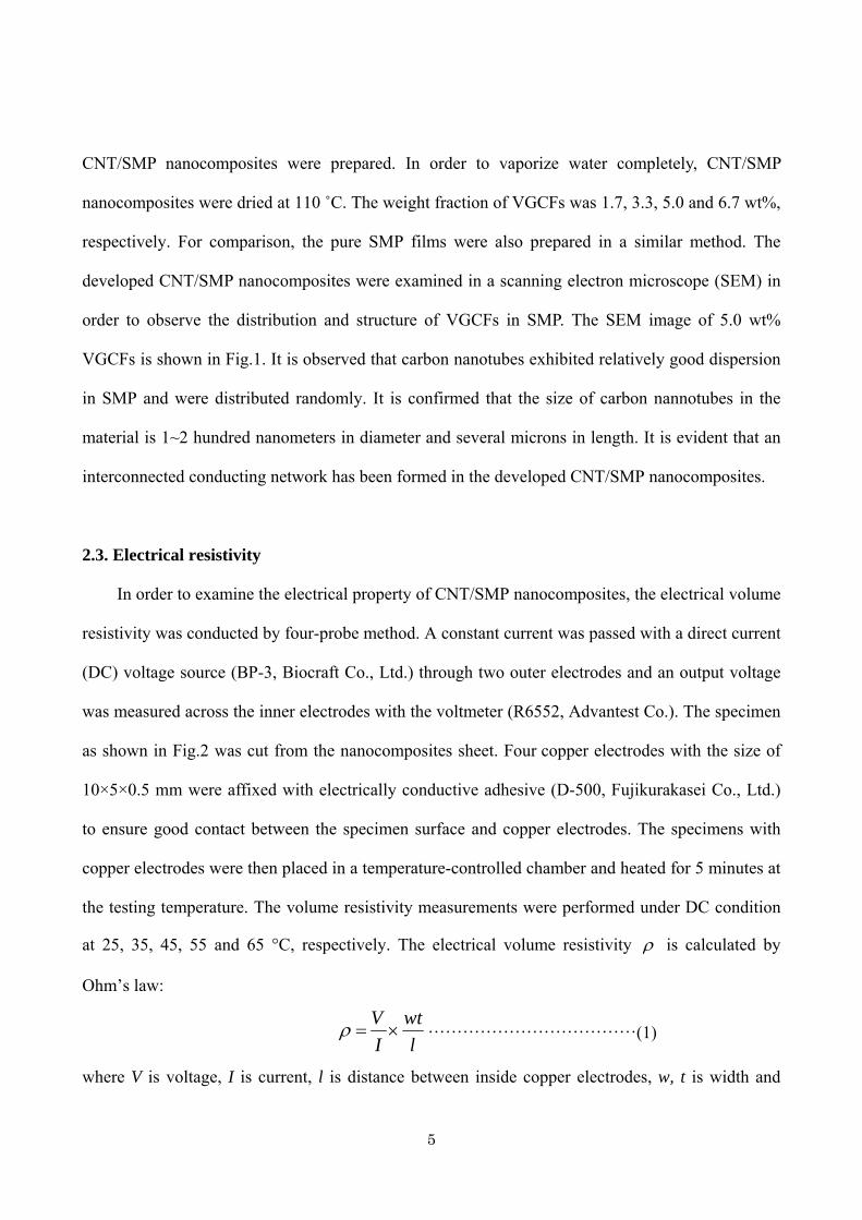
In order to examine the electrical property of CNT/SMP nanocomposites, the electrical volume
resistivity was conducted by four-probe method. A constant current was passed with a direct current
(DC) voltage source (BP-3, Biocraft Co., Ltd.) through two outer electrodes and an output voltage
was measured across the inner electrodes with the voltmeter (R6552, Advantest Co.). The specimen
as shown in Fig.2 was cut from the nanocomposites sheet. Four copper electrodes with the size of
10×5×0.5 mm were affixed with electrically conductive adhesive (D-500, Fujikurakasei Co., Ltd.)
to ensure good contact between the specimen surface and copper electrodes. The specimens with
copper electrodes were then placed in a temperature-controlled chamber and heated for 5 minutes at
the testing temperature. The volume resistivity measurements were performed under DC condition
at 25, 35, 45, 55 and 65 °C, respectively. The electrical volume resistivity ρ is calculated by
Ohm’s law:
lwt
IV×=ρ ………………………………(1)
where V is voltage, I is current, l is distance between inside copper electrodes, w, t is width and
5
thickness of the specimen, respectively.
2.4. Electromagnetic Interference (EMI) Shielding Effectiveness (SE)
The methods such as free space method, shielding box method, coaxial transmission line
method are often used to evaluate an electromagnetic shielding material. For a millimeter wave
band, the technique to evaluate EMI SE is known widely with two antennas arranged face to face. A
specimen much larger than the opening area of a horn antenna is required because of the radiation
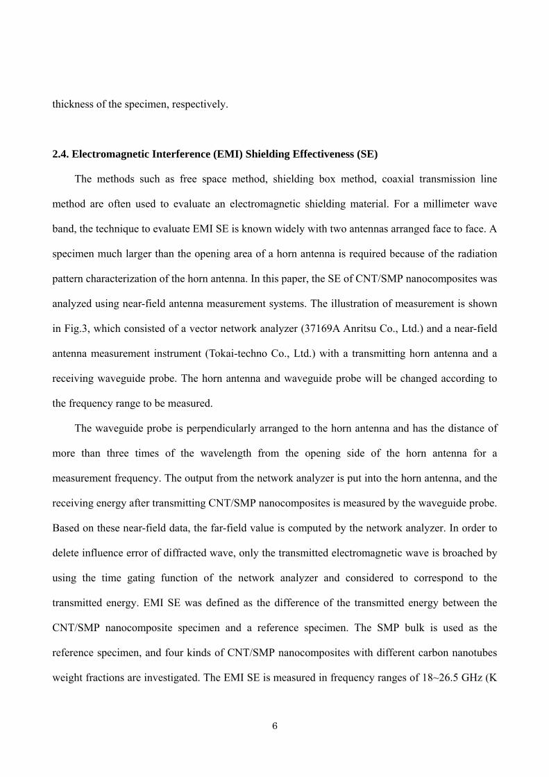
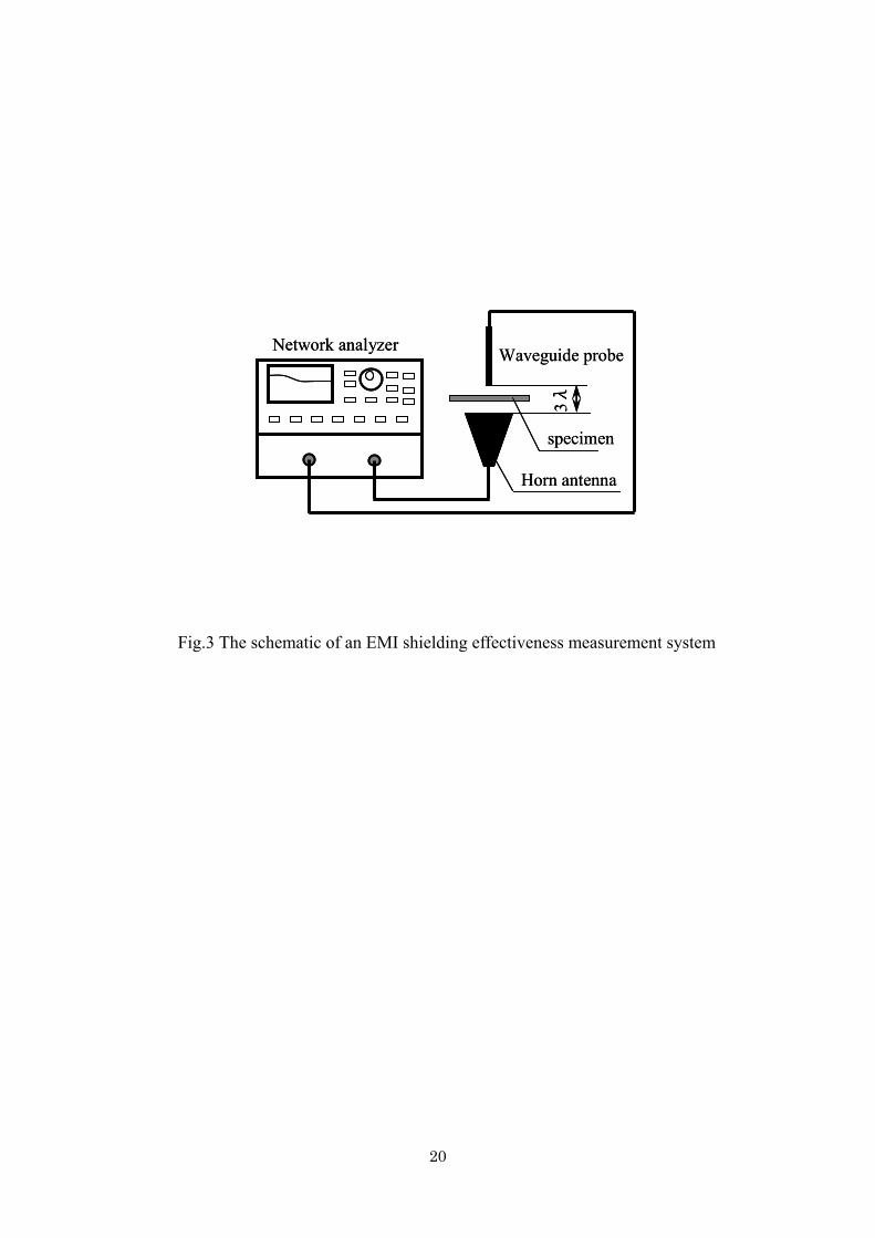
pattern characterization of the horn antenna. In this paper, the SE of CNT/SMP nanocomposites was
analyzed using near-field antenna measurement systems. The illustration of measurement is shown
in Fig.3, which consisted of a vector network analyzer (37169A Anritsu Co., Ltd.) and a near-field
antenna measurement instrument (Tokai-techno Co., Ltd.) with a transmitting horn antenna and a
receiving waveguide probe. The horn antenna and waveguide probe will be changed according to
the frequency range to be measured.
The waveguide probe is perpendicularly arranged to the horn antenna and has the distance of
more than three times of the wavelength from the opening side of the horn antenna for a
measurement frequency. The output from the network analyzer is put into the horn antenna, and the
receiving energy after transmitting CNT/SMP nanocomposites is measured by the waveguide probe.
Based on these near-field data, the far-field value is computed by the network analyzer. In order to
delete influence error of diffracted wave, only the transmitted electromagnetic wave is broached by
using the time gating function of the network analyzer and considered to correspond to the
transmitted energy. EMI SE was defined as the difference of the transmitted energy between the
CNT/SMP nanocomposite specimen and a reference specimen. The SMP bulk is used as the
reference specimen, and four kinds of CNT/SMP nanocomposites with different carbon nanotubes
weight fractions are investigated. The EMI SE is measured in frequency ranges of 18~26.5 GHz (K
6
band), 33~50 GHz (Q band) and 50~75 GHz (V band) in the horn antenna and waveguide probe,
respectively. In order to elucidate the influence of the specimen thickness on EMI SE, two different
thicknesses, 0.5 mm and 3 mm, are also prepared.
3. Results and Discussion
3.1. Electrical resistivity results
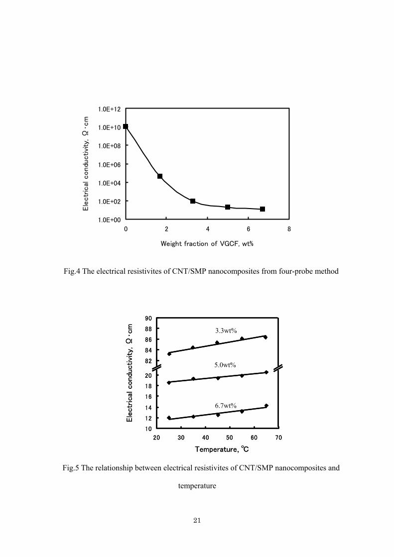
The electrical resistivities of CNT/SMP nanocomposites for different weight fractions at room
temperature are shown in Fig.4. The electrical resistivity decreased with increasing the weight
fractions of carbon nanotubes. It is just as expected the CNT/SMP nanocomposites possess
electrical conductivity due to the addition of carbon nanotubes. The electrical resistivity of 1.7 wt%
VGCFs is larger than others. For the weight fraction over 3.3 wt%, the electrical resistivity dropped
remarkably. This phenomenon is called as percolation. The big drop indicates the percolation
threshold value of carbon nanotubes, VGCFs, in SMP for electrical resistivity is less than 3.3 wt%.
Shuying et al. [6] showed that the percolation threshold value for VGCF/liquid crystal polymer
composites is 5.0 wt% VGCFs and Lozano [28] et al. showed that the percolation threshold value of
VGCNF/Polypropylene composites is 18 wt% VGCFs. It is evident that for the matrix of shape
memory polymer the VGCFs are dispersed to form an interconnected conducting network due to
straight-chain molecules in polyurethane series of shape memory polymer used in this paper. It is
known that the nanotubes content needed for percolation is strongly dependent on the ability to
form an interconnected nanotube network. With the solvent and ultrasonic vibration for the
dispersion of VGCFs in shape memory polymer, the VGCFs are distributed in SMP matrix
uniformly and easily and resulted in low percolation threshold.
The electrical resistivities of CNT/SMP nanocomposites at different testing temperatures are
shown in Fig.5. The electric resistivities became high with the rise of temperature. For CNT/SMP
7
nanocomposites, the free electrons in VGCFs contribute electricity. The movement of these free
electrons may be barred due to the molecules in a polymer matrix and this may cause resistance
increase against a body. When the temperature arises and the movement of molecules becomes
active, the collision frequency of free electrons increases and then electrical resistivity may become
large. Therefore, for CNT/SMP nanocomposites, the electrical resistivity increased almost linearly
with temperature like metal. If the electrical resistivity at 0 °C is set to be 0ρ the electrical
resistivity ρ at temperature T can be expressed as follows.
)1(0 Tαρρ += ………………………………(2)
where α is the temperature coefficient representing the rate of electrical resistivity.
3.2. Prediction of EMI Shielding Effectiveness
Electromagnetic wave consists of a magnetic field (H-field) and electric field (E-field) and
changes periodically, while the two components induct each other and propagates at right angles to
the plane containing two components perpendicular each other. The ratio of E-field to H-field is
defined as wave impedance (Zw, in ohms). Large impedance characterizes electric fields and small
one is to magnetic fields. In the case of far field and plane wave conditions, the ratio of E-field to
H-field remains constant and equal to 120π Ω, the intrinsic impedance of free space. In EMI
shielding, there are two regions, the near field shielding region and far field shielding region, need
to be considered. When the distance between the radiation source and the shield material is larger
than πλ 2/ (where λ is the wavelength of the source wave), it is in the far field shielding region.
The theory of electromagnetic plane wave is generally applied for EMI shielding in this region.
When the distance is less than πλ 2/ , it is in the near field shielding region and the theory based on
the contribution of electric and magnetic dipoles is used for EMI shielding [5, 12, 40].
Shielding effectiveness, SE (dB), is a parameter for the reduction of EMI at a specific frequency
8
due to a shield and is defined as: [5, 40]
ttt HH
EE
PP
SE 000 log20log20log10 === ……………(3)
where , and are the energy, the electric and magnetic field intensity incident on the
shield and , and are the counterparts transmitted through the shield.
0P 0E 0H
tP tE tH
The EMI attenuation offered by a shield may depend on three mechanisms. The first is usually
the reflection of the wave from the shield. The second is the absorption of the wave as it passes
through the shield. The third is due to the re-reflections, i.e. the multiple reflections of the waves at
various surfaces or interfaces within the shield. The reflection loss is a function of the ratio rr µσ ,
whereas the absorption loss is a function of the product rrµσ , where rσ is the electrical
conductivity of the shield relative to copper and rµ is the magnetic permeability of the shield
relative to free space. The multiple reflections, however, require the presence of large surface areas
(e.g. a porous or foam material) or interface areas (e.g. a composite material containing fillers that
have large surface area) in the shield. The loss connected with multiple reflections can be neglected
when the distance between the reflecting surfaces or interfaces is large enough compared to the skin
depth [5, 7], which in meters is defined:
µσπδ
f1
= ……………(4)
where is the frequency (in Hz), f µ is the magnetic permeability by rµµµ 0= ,
H m
70 104 −×= πµ
-1 is the absolute permeability of free space (air), and σ is the electrical conductivity in Ω-1
m-1. For a VGCF/SMP nanocomposite, since it can be considered as a non-magnetic substance, we
have 1=rµ .
The shielding effectiveness (SE) for a conductive material can be expressed by the following
equation.
)(dBARSE += ……………(5)
9
where R is the first reflection loss of the electromagnetic wave, and A is the absorption loss of the
energy of the electromagnetic wave. According to the report by Morita et al. [41], when 3.1≥δt ,
the reflection loss R (dB) can be expressed as follows:
⎟⎠
⎞⎜⎝
⎛=
2220 0δσZ
LogR …………(6)
And then the absorption loss, A (dB), can be evaluated from the equation as follows:
δtA 686.8= …………(7)
Therefore,
δδσ tZ
LogSE 68.822
20 0 +⎟⎠
⎞⎜⎝
⎛= …………(8)
where, π1200 =Z , t is the thickness (m) of a specimen . It is observed that SE in equation (8) is a
function of resistivity, thickness and measurement frequency for a shied material.
When 3.1≤δt , SE will result in following formula.
⎟⎠⎞
⎜⎝⎛ +=
2120 0 σtZ
LogSE …………(9)
3.3. Time Domain Property of Eelectromagnetic Wave
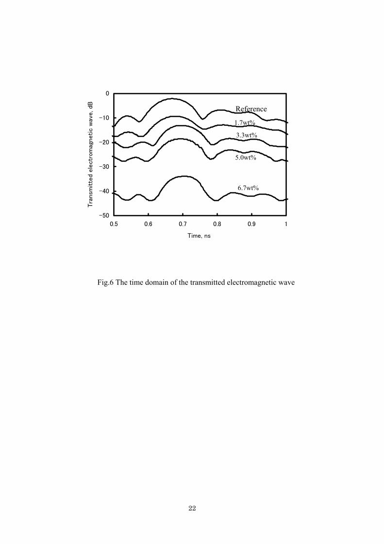
The electromagnetic wave through a shield material is measured and then far-field values are
computed using a network analyzer. Then these values are converted by inverse Fourier transform,
and the time dependence of the transmitted electromagnetic wave is obtained. The typical relation
between the time and transmitted electromagnetic waves is shown in Fig.6 at V-band for the
specimen with 3 mm thickness. The transmitted electromagnetic wave is observed within 0.6~0.8 ns
for CNT/SMP nanocomposites and SMP bulk. When VGCFs weight fraction increases, the peak of
transmitted electromagnetic wave decreased and shifted to right side (delay). This means that EMI
SE will increase with the increment of VGCFs weight fraction. Since the transmitted
electromagnetic waves were only broached by the time gating function in the network analyzer they
10
should correspond to the transmitted energy. The transmitted electromagnetic waves reached after
0.8 ns were the diffracted ones detouring around the specimen.
3.4. Shielding Effectiveness of CNT/SMP Nanocomposites
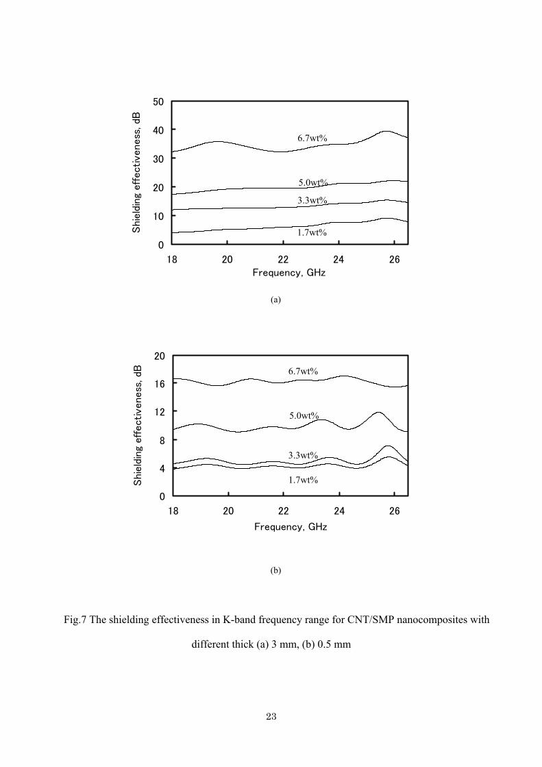
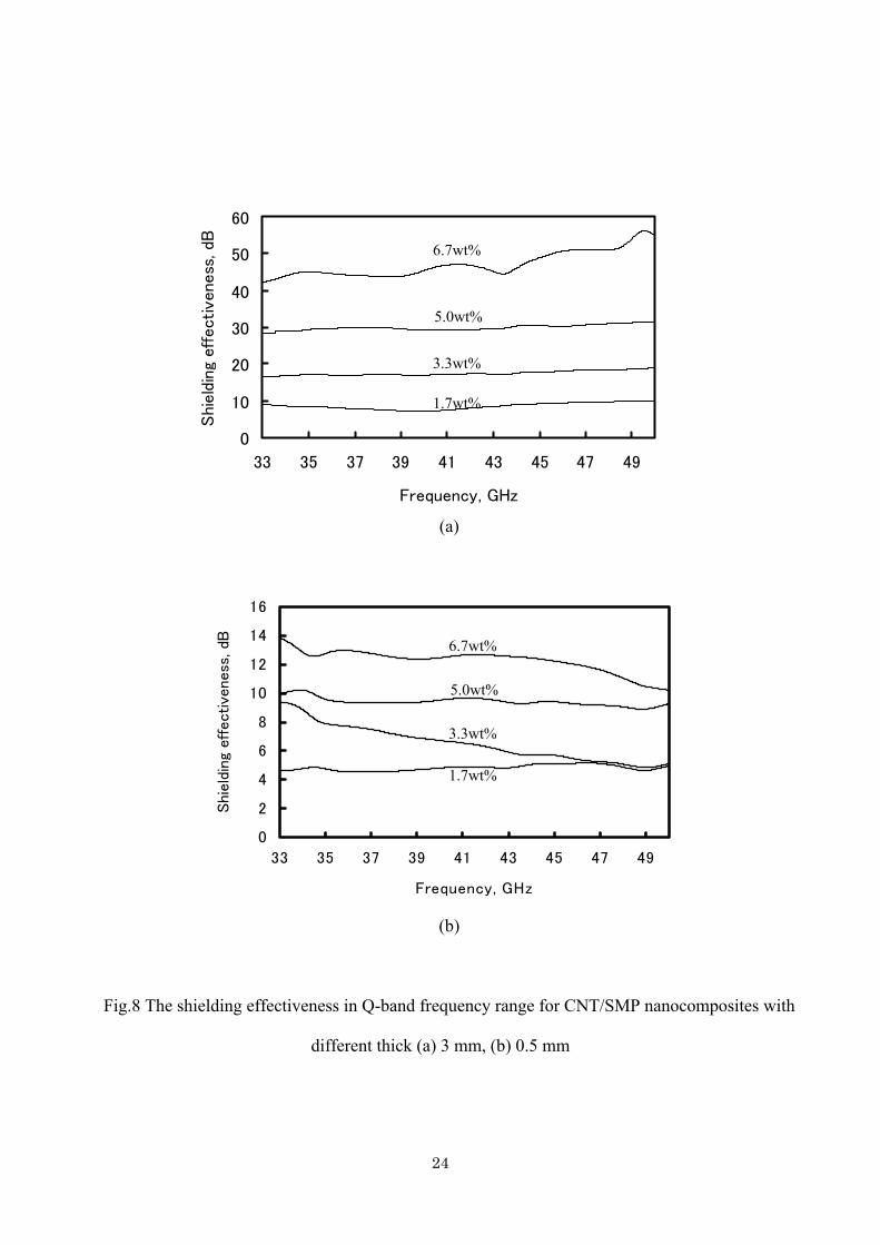
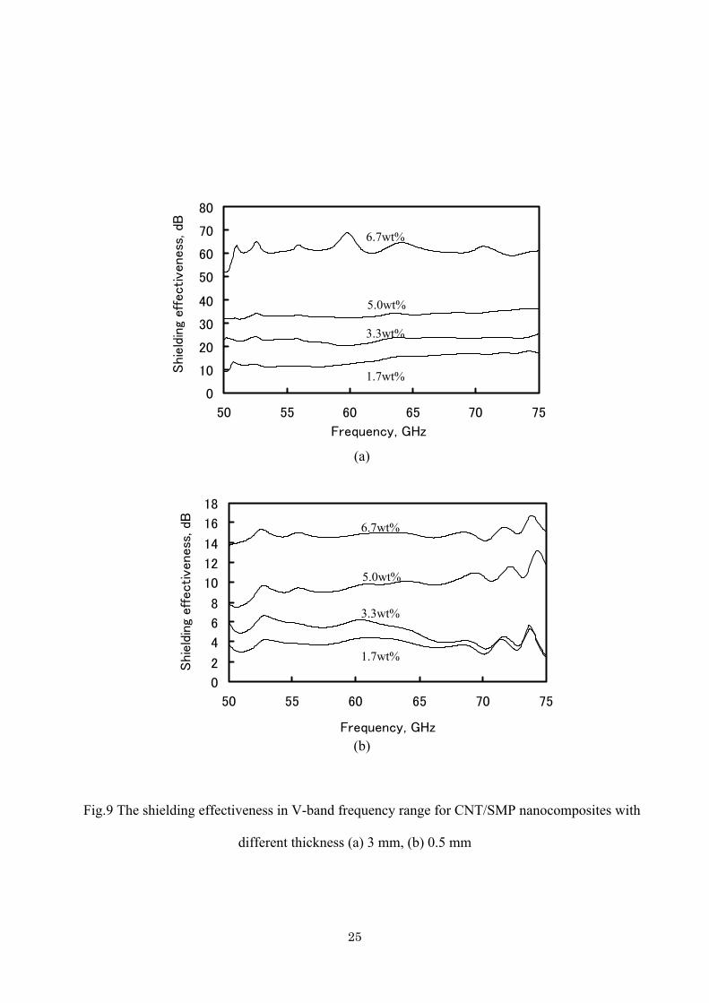
The EMI SE of CNT/SMP nanocomposites for different bands and shielding thicknesses is
shown in Fig.7-9. For the variation of the thickness of a shielding material under the same
frequency condition, the materials with 3 mm thickness show the higher EMI SE compared to the
0.5 mm. According to the equation (7), it is clear that the absorption loss is in proportion relation to
the thickness of a shielding material. When the thickness increases EMI SE will have a large value.
It is observed that EMI SE of CNT/SMP nanocomposites increased with VGCFs weight
fraction at all frequency bands. The higher the frequency, the higher the value of EMI SE. For the
material of 6.7 wt% VGCFs and 3 mm thickness, the value of EMI SE exceeded over 30 dB for any
of three frequency bands, and its maximum value reached 65 dB. The value of EMI SE indicates
how much incident signal is blocked by the shielding medium. For the value of 10dB EMI SE, this
means 90 % of incident signal is blocked, and for 20 dB, 99 % of incident signal is blocked. Many
researches indicate that the reduction of signal strength by 30 dB would be adequate for 50 % cases
in the applications of automotive and computer industries. And the reduction by 40 dB would fulfill
95 % of the requirements [42]. It is clear that CNT/SMP nanocomposites are excellent shielding
materials for electromagnetic interference, especially at high frequency.
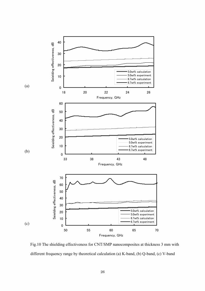
For CNT/SMP nanocomposites for 6.7 wt% and 5.0 wt% of VGCFs with 3 mm thickness, the
value of δt at maximal testing frequency 75 GHz is 4.72 and 3.78, respectively. Thus, using
equation (8), the values of MEI SE for these two materials can be calculated. The relationships
between MEI SE of CNT/SMP nanocomposites for 6.7 wt% and 5.0 wt% VGCFs with 3mm
thickness and the frequency at three bands are shown in Fig.10. In the testing frequency bands, the
11
EMI SE for CNT/SMP nanocomposite with 6.7 wt% VGCFs is larger than that for 5.0 wt%. When
frequency becomes large the rate of increment for EMI SE in 6.7 wt% one is larger than that in 5.0
wt%. Making a comparison between experimental results and theoretical ones for CNT/SMP
nanocomposite with 6.7 wt% VGCFs, the difference is 10 dB at K band, and about 20 dB at Q band
and V band. The predicted value is smaller than experimental one. However, for CNT/SMP
nanocomposite with 5.0 wt% VGCFs, no obvious difference at K band and only small difference of
8 dB at Q band and V band are observed. This difference may be contributed due to multiple
reflection, which was not considered in the prediction.
4. Conclusions
In this study, the nanocomposites with carbon nanotubes (CNTs) and shape memory polymer
(SMP) were developed and their electrical resistivity and electromagnetic interference shielding
effectiveness (EMI SE) were examined. The results obtained are concluded as follows:
1. The electrical resistivity of CNT/SMP nanocomposites decreased with increasing the weight
fraction of VGCFs at each testing temperature. The electrical resistivity for the developed
nanocomposites is dependant obviously on temperature with a linear relation like metals. It is found
the percolation threshold of VGCFs in shape memory polymer is about 10 wt%.
2. The EMI SE of CNT/SMP nanocomposites have a strong dependence of carbon nanotube
content and the specimen thickness at all of three frequency bands. The higher frequency, the larger
EMI SE. The prediction for EMI SE is analyzed. For the materials with 5.5wt% VGCFs both
experiment and analysis will agree well, and theoretical prediction proposed for EMI SE may be
respected for a practical use.
Acknowledgments
12
This work was supported by Kyoto Prefectural Technology Center for Small and Medium
Enterprises. The author (Q.-Q. Ni) gratefully acknowledges the support of K. C. Wong Education
Foundation, Hong Kong, and the key laboratory of Ministry of Education in Zhejiang Sci-Tech
University, China and the CLUSTER of Ministry of Education, Culture, Sports, Science and
Technology (MEXT), Japan.
References
[1] Hatakeyama K, Togawa H. Simplified measurement method of electromagnetic wave shielding
and absorbing characteristics in mm-wave. IEICE Trans B-П 1998;J81-B-П:651-656.
[2] Harada Y. Research and development of frequency resources in MPT. J IEICE 1995;78:741-744.
[3] Das NC, Chaki Tk, Khastgir D, Chakraborty A. Electromagnetic interference shielding
effectiveness of ethylene vinyl acetate based conductive composites containing carbon fillers. J
Appl Polym Sci 2001;80:1601-1608.
[4] Chou K-S, Huang K-C, Shih Z-H. Effect of mixing process on electromagnetic interference
shielding effectiveness of nickel/acrylonitrile-butadiene-styrene composites. J Appl Polym Sci
2005;97:128-135.
[5] Wang Y, Jing X. Intrinsically conducting polymers for electromagnetic interference shielding.
Polym Adv Technol 2005;16:344-351.
[6] Yang S, Lozano K, Lomeli A, Foltz HD, Jones R. Electromagnetic interference shielding
effectiveness of carbon nanofiber/LCP composites. Compos: Part A 2005;36:691-697.
[7] Chung DLL. Electromagnetic interference shielding effectiveness of carbon material. Carbon
2001;39:279-285.
[8] Shinagawa S, Kumagai Y, Urabe K. Conductive papers containing metallized polyester fibers
for electromagnetic interference shielding. J Porous Mater 1999;6:185-190.
13
[9] Heiser JA, King JA, Konell JP, Sutter LL. Shielding effectiveness of carbon-filled nylon 6,6.
Polym Compos 2004;25:407-416.
[10] Lee BO, Woo WJ, Park HS, Hahm HS, Wu JP, Kim MS. Influence of aspect ratio and effect
on EMI shielding of coating materials fabricated with carbon nanofiber/PVDF. J Mater Sci
2002;37:1839-1843.
[11] Das NC, Chaki TK, Khastgir D. Electromagnetic interference shielding effectiveness of
conductive carbon black and carbon fiber-filled composites based on rubber and rubber blends.
Adv Polym Techn 2001;20:226-236.
[12] Das NC, Khasgir D, Chaki TK, Chakraborty A. Electromagnetic interference shielding
effectiveness of carbon black and carbon fiber filled EVA and NR based composites. Compos:
Part A 2000;31:1069-1081.
[13] Luo X, Chung DDL. Electromagnetic interference shielding using continuous carbon-fiber
carbon-matrix and polymer-matrix composites. Compos: Part B 1999;30:227-231.
[14] Ma C-C.M, Huang Y-L, Kuan H-C, Chiu Y-S. Preparation and electromagnetic interference
shielding characteristics of novel carbon-nanotube/siloxane/poly (urea urethane)
nanocomposites. J Polym Sci: Part B: Polym Phys 2005;43:345-358.
[15] Xu Y, Higgins B, Brittain WJ. Bottom-up synthesis of PS-CNT nanocomposites. Polym
2005;46:799-810.
[16] Rodriguez NM. A review of catalytically grown carbon nanofibers. J Mater Res
1993;8:3233-3250.
[17] Heremans J, Beetz Jr. CP. Thermal conductivity and thermopower of vapor-grown graphite
fibers. Phys Rev B 1985;32:1981-1986.
[18] Heremans J. Electrical conductivity of vapor-grown carbon fibers. Carbon 1985;23:431-436.
[19] Endo. M, Kim YA, Hayashi T, Nishimura K, Matusita T, Miyashita K, Dresselhaus MS.
14
Vapor-grown carbon fibers (VGCFs): Basic properties and their battery applications. Carbon
2001;39:1287-1297.
[20] Patton RD, Pittman Jr. CU, Wang L, Hill JR, Day A. Ablation, mechanical and thermal
conductivity properties of Vapor grown carbon fiber/phenolic matrix composites. Compos:
Part A 2002;33:243-251.
[21] Patton RD, Pittman Jr. CU, Wang L, Hill JR. Vapor grown carbon fiber composites with
epoxy and poly(phenylene sulfide) matrices. Compos: Part A 1999;30:1081-1091.
[22] Richard P, Prasse T, Cavaille Y, Chazeau L, Gauthier C, Duchet J. Reinforcement of rubbery
epoxy by carbon nanofibres. Mater Sci Eng A 2003;352:344-348.
[23] Carneiro OS, Covas JA, Bernardo CA, Caldeira G, Van Hattum FWJ, Ting JM, Alig RL, Lake
ML. Production and assessment of polycarbonate composites reinforced with vapour-grown
carbon fibres. Compos Sci Technol 1998;58:401-407.
[24] Chen Y-M, Ting J-M. Ultra high thermal conductivity polymer composites. Carbon
2002;40:359-362.
[25] Takahashi T, Yonetake K, Koyama K, Kikuchi T. Polycarbonate crystallization by
vapor-grown carbon fiber with and without magnetic field. Macromol. Rapid Commun.
2003;24:763-767.
[26] Kuriger RJ, Alam MK, Anderson DP, Jacobsen RL. Processing and characterization of aligned
vapor-grown carbon fiber reinforced polypropylene. Compos: Part A 2002;33:53-62.
[27] Lozano K, Barrera EV. Nanofiber-reinforced thermoplastic composites. I. thermoanalytical and
mechanical analyses. J Appl Polym Sci 2001;79:125-133.
[28] Lozano K, Bonilla-Rios J, Barrera EV. A study on nanofiber-reinforced thermoplastic
composites (П): investigation of the mixing rheology and conduction properties. J Appl
Polym Sci 2001;80:1162-1172.
15
[29] Compos Struct. To be Online.
[30] Irie M. Development of shape memory polymers. CMC, 2000.
[31] Lendlein A, Kelch S. Shape-memory polymers. Angew Chem Int Ed 2002;41:2034-2057.
[32] Tobushi H, Okumura K, Endo M, Hayashi S. Thermomechanical properties
polyurethane-shape memory polymer form. J Intell Mater Syst Struct 2001;12:283-287.
[33] Tobushi H, Hayahi S, Ikai A, Hara H. Basic deformation properties of a polyurethane-series
shape memory polymer film. Trans Jpn Soc Mech Eng A 1996; 62(594):576-582.
[34] Jeong HM, Lees JB, Lee Y, Kim BK. Shape memory polyurethane containing mesogenic
moiety, J Mater Sci 2000;35;279-283.
[35] Lin JR, Chen LW. Study on shape-memory behavior of polyether-based polyurethanes. I.
Influence of the hard-segment content. J Appl Polym Sci 1998;69:1563-1574.
[36] Lin JR, Chen LW. Study on shape-memory behavior of polyether-based polyurethanes. II.
Influence of the soft-segment molecular weight. J Appl Polym Sci 1998;69:1575-1586.
[37] Ohki Ta, Ni Q-Q, Ohsako N, Iwamoto M. Mechanical and shape memory behavior of
composites with shape memory polymer. Compos: Part A 2004;35:1065-1073.
[38] Gall K, Dunn ML, Liu Y, Finch D, Lake M, Munshi NA. Shape memory polymer
nanocomposites. Acta Materialia 2002;50:5115-5126.
[39] Liang C, Rogers CA, Malafeew E. Investigation of shape memory polymers and their hybrid
composites. J Intell Mater Syst Struct 1997;8:380-386.
[40] Lu G, Li X, Jiang H. Electrical and shielding properties of ABS resin filled with nickel-coated
carbon fibers. Comp Sci Technol 1996;56:193-200.
[41] Morita T, Sumihiro S, Okumura K. Measuring the electro magnetic shielding effectiveness of
materials using the metal spray coating technique. IEICE Technical Report. Electromagnetic
Compatibility 2000;99:19-24.
16
[42] Simon RM. EMI shielding through conductive plastics. Polym Plast Technol Eng 1981;
17(1):1-10
17
The List of captions for Figures
Fig.1 SEM micrograph of CNT/SMP nanocomposite with 5.0 wt% VGCFs.
Fig.2 Specimen used for measurement of electrical resistivity by four-probe method.
Fig.3 The schematic of an EMI shielding effectiveness measurement system.
Fig.4 The electrical resistivites of CNT/SMP nanocomposites by four-probe method
Fig.5 The relationships between electrical resistivites and temperature for different CNT/SMP
nanocomposites
Fig.6 The transmitted electromagnetic wave in a time domain.
Fig.7 The shielding effectiveness in K-band frequency range for CNT/SMP nanocomposites with
different thicknesses, (a) 3 mm, (b) 0.5 mm.
Fig.8 The shielding effectiveness in Q-band frequency range for CNT/SMP nanocomposites with
different thicknesses, (a) 3 mm, (b) 0.5 mm.
Fig.9 The shielding effectiveness in V-band frequency range for CNT/SMP nanocomposites with
different thicknesses, (a) 3 mm, (b) 0.5 mm.
Fig.10 Theoretical prediction of shielding effectiveness for CNT/SMP nanocomposites with 3mm
thickness, (a) K-band, (b) Q-band, (c) V-band.
18
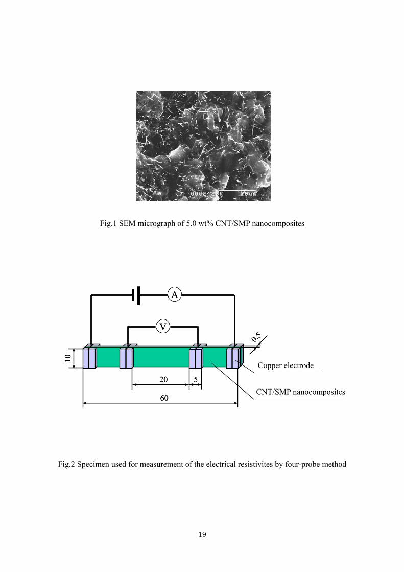
Fig.1 SEM micrograph of 5.0 wt% CNT/SMP nanocomposites
A
V
60
20 5
10
0.5
A
V
60
20 5
10
0.5
Copper electrode
CNT/SMP nanocomposites
Fig.2 Specimen used for measurement of the electrical resistivites by four-probe method
19
Network analyzer
Horn antenna
Waveguide probe
3λ
specimen
Network analyzer
Horn antenna
Waveguide probe
3λ
specimen
Fig.3 The schematic of an EMI shielding effectiveness measurement system
20
1.0E+00
1.0E+02
1.0E+04
1.0E+06
1.0E+08
1.0E+10
1.0E+12
0 2 4 6 8
Weight fraction of VGCF, wt%
Ele
ctr
ical
condu
ctivi
ty, Ω
・cm
Fig.4 The electrical resistivites of CNT/SMP nanocomposites from four-probe method
Temperature,
Ele
ctr
ical
condu
ctivi
ty, Ω
・cm
82
84
86
88
90
10
12
14
16
18
20
20 30 40 50 60 70
Temperature,
Ele
ctr
ical
condu
ctivi
ty, Ω
・cm
82
84
86
88
90
10
12
14
16
18
20
20 30 40 50 60 70
3.3wt%
5.0wt%
6.7wt%
Fig.5 The relationship between electrical resistivites of CNT/SMP nanocomposites and
temperature
21
-50
-40
-30
-20
-10
0
0.5 0.6 0.7 0.8 0.9
Time, ns
Tra
nsm
itte
d ele
ctr
om
agnetic w
ave, dB Reference
1.7wt%
3.3wt%
5.0wt%
6.7wt%
1
Fig.6 The time domain of the transmitted electromagnetic wave
22
0
10
20
30
40
50
18 20 22 24 26Frequency, GHz
Shie
ldin
g eff
ective
ness
, dB
1.7wt%
3.3wt%
5.0wt%
6.7wt%
(a)
0
4
8
12
16
20
18 20 22 24 26
Frequency, GHz
Shie
ldin
g eff
ectiveness
, dB
1.7wt%
3.3wt%
5.0wt%
6.7wt%
(b)
Fig.7 The shielding effectiveness in K-band frequency range for CNT/SMP nanocomposites with
different thick (a) 3 mm, (b) 0.5 mm
23
0
10
20
30
40
50
60
33 35 37 39 41 43 45 47 49
Frequency, GHz
Shi
eldin
g ef
fect
iven
ess
, dB
1.7wt%
3.3wt%
5.0wt%
6.7wt%
(a)
0
2
4
6
8
10
12
14
16
33 35 37 39 41 43 45 47 49
Frequency, GHz
Shie
ldin
g eff
ective
nes
s, d
B
1.7wt%
3.3wt%
5.0wt%
6.7wt%
(b)
Fig.8 The shielding effectiveness in Q-band frequency range for CNT/SMP nanocomposites with
different thick (a) 3 mm, (b) 0.5 mm
24
0
10
20
30
40
50
60
70
80
50 55 60 65 70 75
Frequency, GHz
Shie
ldin
g ef
fectiven
ess,
dB
1.7wt%
3.3wt%
5.0wt%
6.7wt%
(a)
(b)
0
2
4
6
8
10
12
14
16
18
50 55 60 65 70 75
Frequency, GHz
Shie
ldin
g eff
ective
nes
s, d
B
1.7wt%
3.3wt%
5.0wt%
6.7wt%
Fig.9 The shielding effectiveness in V-band frequency range for CNT/SMP nanocomposites with
different thickness (a) 3 mm, (b) 0.5 mm
25
0
10
20
30
40
18 20 22 24 26
Frequency, GHz
Seie
ldin
g effectiveness
, dB
5.0wt% calculation5.0wt% experiment
6.7wt% calculation6.7wt% experiment
(a)
0
10
20
30
40
50
60
33 38 43 48
Frequency, GHz
Seie
ldin
g effectiveness
, dB
5.0wt% calculation5.0wt% experiment
6.7wt% calculation6.7wt% experiment(b)
0
10
20
30
40
50
60
70
50 55 60 65 70
Frequency, GHz
Seie
ldin
g effectiveness
, dB
5.0wt% calculation5.0wt% experiment
6.7wt% calculation6.7wt% experiment
(c)
Fig.10 The shielding effectiveness for CNT/SMP nanocomposites at thickness 3 mm with
different frequency range by theoretical calculation (a) K-band, (b) Q-band, (c) V-band
26