electromagnetic interference with implantable...
TRANSCRIPT

441
Exogenous electric and magnetic fields (EMFs) from sources such as high-voltage power lines, substations, electronic
article surveillance systems, or electrical appliances induce noise signals in the human body. They superimpose intrinsic heart signals and may lead to electromagnetic interference (EMI) with active implantable medical devices such as cardiac pacemakers or implantable cardioverter-defibrillators (ICDs).
Clinical Perspective on p 450
First reports of EMI with cardiac implants were published in the early 1960s.1 During the last decades, many different studies dealing with EMI have been published; however, to date there is no conclusive evidence as to which sources of
extremely low-frequency EMFs may disturb cardiac pacemak-ers or ICDs.
New indications for ICD therapy, especially the implantation for primary prevention of sudden cardiac death, have substan-tially increased the number of patients carrying an ICD, thus emphasizing the need for further investigation and regulation. In Germany alone, there were 21 609 ICD implantations in 2006, increasing to 42 261 in 2012.2,3 Many of these devices were implanted in relatively young patients possibly still work-ing with the risk of strong field exposure in specific occupa-tional environments (eg, technician in a power plant). In 2011, 51.1% of all patients with first ICD implantation were <70 years of age and 25.5% were <60 years of age in Germany.4
Background—The number of implantable cardioverter-defibrillators (ICDs) for the prevention of sudden cardiac death is continuing to increase. Given the technological complexity of ICDs, it is of critical importance to identify and control possible harmful electromagnetic interferences between various sources of electromagnetic fields and ICDs in daily life and occupational environments.
Methods and Results—Interference thresholds of 110 ICD patients (1-, 2-, and 3-chamber ICDs) were evaluated in a specifically developed test site. Patients were exposed to single and combined electric and magnetic 50-Hz fields with strengths of up to 30 kV·m−1 and 2.55 mT. Tests were conducted considering worst-case conditions, including maximum sensitivity of the device or full inspiration. With devices being programmed to nominal sensitivity, ICDs remained unaffected in 91 patients (83%). Five of 110 devices (5%) showed transient loss of accurate right ventricular sensing, whereas 14 of 31 (45%) of the 2- and 3-chamber devices displayed impaired right atrial sensing. No interference was detected in 71 patients (65%) within the tested limits with programming to maximum sensitivity, whereas 20 of 110 subjects (18%) exhibited right ventricular disturbances and 19 of 31 (61%) subjects exhibited right atrial disturbances.
Conclusions—Extremely low-frequency daily-life electromagnetic fields do not disturb sensing capabilities of ICDs. However, strong 50-Hz electromagnetic fields, present in certain occupational environments, may cause inappropriate sensing, potentially leading to false detection of atrial/ventricular arrhythmic events. When the right atrial/right ventricular interferences are compared, the atrial lead is more susceptible to electromagnetic fields.
Clinical Trial Registration—URL: http://clinicaltrials.gov/ct2/show/NCT01626261. Unique identifier: NCT01626261. (Circulation. 2014;129:441-450.)
Key Words: defibrillators, implantable ◼ electromagnetic fields ◼ power sources ◼ threshold limit values
© 2013 American Heart Association, Inc.
Circulation is available at http://circ.ahajournals.org DOI: 10.1161/CIRCULATIONAHA.113.003081
Received April 7, 2013; accepted October 10, 2013.From the Department of Internal Medicine I (Cardiology, Pneumology, Angiology) (A.N., C.K., M.Z., B.B., N.M., P.S.) and Research Center for
Bioelectromagnetic Interaction at the Institute of Occupational Medicine; former at the Institute of Hygiene and Environmental Medicine (S.J., D.S., J.S.), University Hospital RWTH Aachen, Aachen, Germany; and Department of Cardiology, Maastricht University Medical Center, Maastricht, The Netherlands (C.K.).
*Drs Napp, Joosten, and Stunder contributed equally.The online-only Data Supplement is available with this article at http://circ.ahajournals.org/lookup/suppl/doi:10.1161/CIRCULATIONAHA.
113.003081-/DC1.Correspondence to Andreas Napp, MD, Department of Internal Medicine I (Cardiology, Pneumology, Angiology), RWTH Aachen University,
Pauwelsstrasse 30, 52074 Aachen, Germany. E-mail [email protected]
Electromagnetic Interference With Implantable Cardioverter-Defibrillators at Power Frequency
An In Vivo Study
Andreas Napp, MD*; Stephan Joosten, MSc*; Dominik Stunder, MSc*; Christian Knackstedt, MD; Matthias Zink, MD; Barbara Bellmann, MD; Nikolaus Marx, MD;
Patrick Schauerte, MD; Jiri Silny, PhD
by guest on June 1, 2018http://circ.ahajournals.org/
Dow
nloaded from
by guest on June 1, 2018http://circ.ahajournals.org/
Dow
nloaded from
by guest on June 1, 2018http://circ.ahajournals.org/
Dow
nloaded from
by guest on June 1, 2018http://circ.ahajournals.org/
Dow
nloaded from
by guest on June 1, 2018http://circ.ahajournals.org/
Dow
nloaded from
by guest on June 1, 2018http://circ.ahajournals.org/
Dow
nloaded from
by guest on June 1, 2018http://circ.ahajournals.org/
Dow
nloaded from
by guest on June 1, 2018http://circ.ahajournals.org/
Dow
nloaded from
by guest on June 1, 2018http://circ.ahajournals.org/
Dow
nloaded from
by guest on June 1, 2018http://circ.ahajournals.org/
Dow
nloaded from
by guest on June 1, 2018http://circ.ahajournals.org/
Dow
nloaded from
by guest on June 1, 2018http://circ.ahajournals.org/
Dow
nloaded from
by guest on June 1, 2018http://circ.ahajournals.org/
Dow
nloaded from
by guest on June 1, 2018http://circ.ahajournals.org/
Dow
nloaded from
by guest on June 1, 2018http://circ.ahajournals.org/
Dow
nloaded from
by guest on June 1, 2018http://circ.ahajournals.org/
Dow
nloaded from
by guest on June 1, 2018http://circ.ahajournals.org/
Dow
nloaded from
by guest on June 1, 2018http://circ.ahajournals.org/
Dow
nloaded from
by guest on June 1, 2018http://circ.ahajournals.org/
Dow
nloaded from
by guest on June 1, 2018http://circ.ahajournals.org/
Dow
nloaded from
by guest on June 1, 2018http://circ.ahajournals.org/
Dow
nloaded from
by guest on June 1, 2018http://circ.ahajournals.org/
Dow
nloaded from

442 Circulation January 28, 2014
Additionally, the number and types of EMF sources have like-wise risen in daily life and occupational environments over the past 2 decades. EMI with ICDs may cause inadequate oversens-ing with subsequent inappropriate shock delivery, inhibition of pacing, or switch to an asynchronous noise mode. Of note, inappropriate shock delivery seems to carry an increased risk for overall survival5 and cause psychological distress.
Safety guidelines of the European Union,6–8 the American National Standards Institute (ANSI),9 and the International Commission on Non-Ionizing Radiation Protection10 for the protection of humans exposed to EMFs do not include patients with medical devices such as ICDs (Table 1). Nevertheless, several product standards for manufacturers provide test meth-odologies (so-called benchmark tests) to evaluate the electro-magnetic compatibility performance of ICDs.11–14 However, these standards achieve electromagnetic compatibility only to a certain degree. It is important to understand that EMI may occur despite conformance of cardiac implants to the specific product standards and the conformance of sources of EMFs to the human exposure safety guidelines according to the ANSI/Association for the Advancement of Medical Instrumentation standard PC69.14 There is a lack of comprehensive data, espe-cially on in vivo exposure, to close the current gap in knowl-edge about the extent to which patients with cardiac implants may be influenced by extremely low-frequency EMFs.
The objective of the present study was to provide sound data on the exposure of ICD patients to extremely low-frequency EMFs to overcome the existing uncertainty among patients and physicians. In a clinical in vivo provocation study, ICD patients were exposed to single and combined 50-Hz EMFs of up to 30 kV·m−1 (electric field strength) and 2.55 mT (magnetic flux density). These are the maximum occupational limits in Germany covering EMFs in the vicinity of high-voltage power lines, power installations, or other power-operated machines.15 We systematically determined the interference thresholds of patients’ ICDs, that is, the first occurrence of a sensing failure under worst-case conditions (eg, maximum sensitivity).
MethodsThe study design was approved by the institutional review com-mittee for Human Research of University Hospital RWTH Aachen (www.clinicaltrials.gov; identifier NCT01626261). It consisted of 2 parts: (1) benchmark tests, that is, computer-based tests with ICDs to develop and validate the method of the provocation study, and (2) a provocation study, that is, a clinical in vivo study with ICD patients to determine the individual interference thresholds.
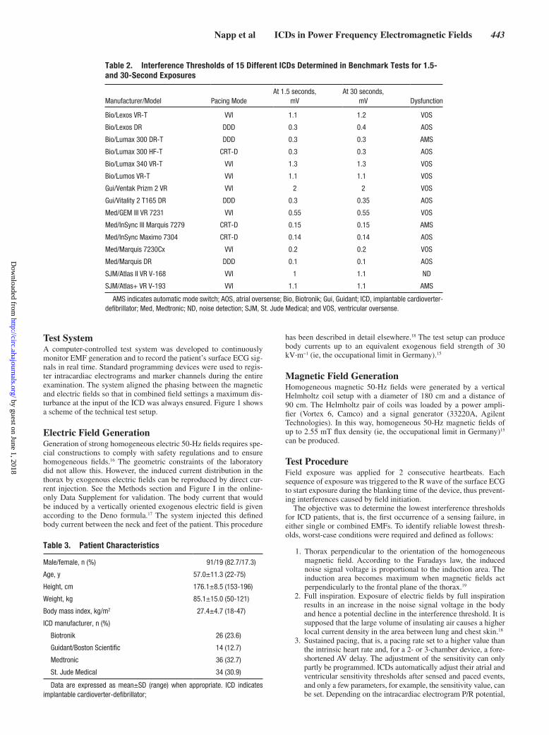
Benchmark TestsThe purpose of the benchmark tests was to determine whether the interference threshold is independent of the duration of expo-sure to validate the method of short-term exposure in the in vivo provocation study. A computer-generated intracardiac electrogram, corresponding to the European product standard EN 45502-2-2,11 superimposed with a 50-Hz sinusoidal noise signal was fed into the pace/sense channel of the ICD to be tested. The injected 50-Hz sinusoidal noise signal simulated the EMF exposure used in the provocation study. Interference thresholds of different ICDs were determined and compared under short-term exposure (1.5 seconds, ≈2 consecutive heartbeats) and long-term exposure (30 seconds). The ICD parameters were set to nominal settings but maximum sensitivity. The reaction of the ICD was monitored by standard programming devices. The amplitude of the 50-Hz sinusoidal noise signal was increased successively until the first sensing failure of the device occurred (ie, the interference threshold) or the maximum amplitude (20 mV peak to peak) was reached. A total of 15 different ICD models were tested (Table 2). ICDs were previously explanted in patients as a result of battery depletion, device infection, or upgrade to a different system.
Provocation StudyIn the provocation study, ICD patients were systematically exposed to EMFs of different intensities to define thresholds of EMI at 50 Hz. For safety reasons, sequences of field exposure in patients were lim-ited to a maximum of 2 consecutive heartbeats (short-term exposure), and ICD therapies for ventricular tachycardia (VT) and ventricular fibrillation (VF) were switched off during the investigation.
Patient PopulationDuring the period of September 2009 to December 2012, all patients presenting to the outpatient pacemaker/ICD clinic of our department were screened for the study. Of 1983 patients consecu-tively requested for routine ambulatory ICD follow-up, 386 patients met the inclusion/exclusion criteria, and 110 gave written informed consent. Inclusion criteria were age between 18 and 75 years and device implantation >4 weeks previously. Exclusion criteria were pacemaker dependency, hyperthyroidism, ineffective oral antico-agulant therapy in case of atrial fibrillation, serum electrolyte disor-ders, clinically manifest infection, myocardial infarction <30 days, and pregnancy.
Pretest examination included a 12-lead ECG, device inter-rogation, and analysis of blood samples (electrolyte levels and coagulation). Body measurements (height, weight, thorax circum-ference, shoulder width) and information about the implanted sys-tem (manufacturer and model of the device and leads, chest X-ray) were documented.
Follow-up examination, immediately after the test and again after 4 weeks, included a 12-lead ECG and device interrogation. No device defects or software resets were seen. Pacing thresholds remained unchanged at the follow-up visits.
All 110 patients who consented to participate in the study were included to obtain a comprehensive picture of interference thresholds of ICDs. Single-chamber ICDs were implanted in 79 patients, dual-cham-ber ICDs in 16 patients, and 3-lead ICD systems (cardiac resynchroniza-tion therapy–defibrillator [CRT-D]) in 15 subjects. One patient (P090) with a dual-chamber ICD was programmed to the VVI mode because of an atrial lead defect. This patient was included as single-chamber ICD. Table 3 shows the characteristics of the 110 patients.
Table 1. Overview of Different Guidelines for the Protection of Humans Exposed to Electric and Magnetic Fields in the General Public and Occupational/Controlled Environments at 50 Hz (These Guidelines Do Not Consider Protection of Patients With Medical Devices)
Environment EU* ICNIRP† ANSI/IEEE‡
General public
Electric field, kV/m 5 5 5
Magnetic field, mT 0.1 0.2 0.904
Occupational
Electric field, kV/m 10 10 20
Magnetic field, mT 0.5 1 2.71
*European Union (EU) guidelines 1999/519/EC from 1999 and 2004/40/EC from 20046,7; new occupational guidelines are currently being discussed in the EU parliament.8
†International Commission on Non-Ionizing Radiation Protection (ICNIRP) guideline from 2010.10
‡American National Standards Institute (ANSI)/Institute of Electrical and Electronics Engineers (IEEE) guideline C95.6 from 2002; limit values also apply to 60 Hz.9
by guest on June 1, 2018http://circ.ahajournals.org/
Dow
nloaded from
Napp et al ICDs in Power Frequency Electromagnetic Fields 443
Test SystemA computer-controlled test system was developed to continuously monitor EMF generation and to record the patient’s surface ECG sig-nals in real time. Standard programming devices were used to regis-ter intracardiac electrograms and marker channels during the entire examination. The system aligned the phasing between the magnetic and electric fields so that in combined field settings a maximum dis-turbance at the input of the ICD was always ensured. Figure 1 shows a scheme of the technical test setup.
Electric Field GenerationGeneration of strong homogeneous electric 50-Hz fields requires spe-cial constructions to comply with safety regulations and to ensure homogeneous fields.16 The geometric constraints of the laboratory did not allow this. However, the induced current distribution in the thorax by exogenous electric fields can be reproduced by direct cur-rent injection. See the Methods section and Figure I in the online-only Data Supplement for validation. The body current that would be induced by a vertically oriented exogenous electric field is given according to the Deno formula.17 The system injected this defined body current between the neck and feet of the patient. This procedure
has been described in detail elsewhere.18 The test setup can produce body currents up to an equivalent exogenous field strength of 30 kV·m−1 (ie, the occupational limit in Germany).15
Magnetic Field GenerationHomogeneous magnetic 50-Hz fields were generated by a vertical Helmholtz coil setup with a diameter of 180 cm and a distance of 90 cm. The Helmholtz pair of coils was loaded by a power ampli-fier (Vortex 6, Camco) and a signal generator (33220A, Agilent Technologies). In this way, homogeneous 50-Hz magnetic fields of up to 2.55 mT flux density (ie, the occupational limit in Germany)15 can be produced.
Test ProcedureField exposure was applied for 2 consecutive heartbeats. Each sequence of exposure was triggered to the R wave of the surface ECG to start exposure during the blanking time of the device, thus prevent-ing interferences caused by field initiation.
The objective was to determine the lowest interference thresholds for ICD patients, that is, the first occurrence of a sensing failure, in either single or combined EMFs. To identify reliable lowest thresh-olds, worst-case conditions were required and defined as follows:
1. Thorax perpendicular to the orientation of the homogeneous magnetic field. According to the Faradays law, the induced noise signal voltage is proportional to the induction area. The induction area becomes maximum when magnetic fields act perpendicularly to the frontal plane of the thorax.19
2. Full inspiration. Exposure of electric fields by full inspiration results in an increase in the noise signal voltage in the body and hence a potential decline in the interference threshold. It is supposed that the large volume of insulating air causes a higher local current density in the area between lung and chest skin.18
3. Sustained pacing, that is, a pacing rate set to a higher value than the intrinsic heart rate and, for a 2- or 3-chamber device, a fore-shortened AV delay. The adjustment of the sensitivity can only partly be programmed. ICDs automatically adjust their atrial and ventricular sensitivity thresholds after sensed and paced events, and only a few parameters, for example, the sensitivity value, can be set. Depending on the intracardiac electrogram P/R potential,
Table 2. Interference Thresholds of 15 Different ICDs Determined in Benchmark Tests for 1.5- and 30-Second Exposures
Manufacturer/Model Pacing ModeAt 1.5 seconds,
mVAt 30 seconds,
mV Dysfunction
Bio/Lexos VR-T VVI 1.1 1.2 VOS
Bio/Lexos DR DDD 0.3 0.4 AOS
Bio/Lumax 300 DR-T DDD 0.3 0.3 AMS
Bio/Lumax 300 HF-T CRT-D 0.3 0.3 AOS
Bio/Lumax 340 VR-T VVI 1.3 1.3 VOS
Bio/Lumos VR-T VVI 1.1 1.1 VOS
Gui/Ventak Prizm 2 VR VVI 2 2 VOS
Gui/Vitality 2 T165 DR DDD 0.3 0.35 AOS
Med/GEM III VR 7231 VVI 0.55 0.55 VOS
Med/InSync III Marquis 7279 CRT-D 0.15 0.15 AMS
Med/InSync Maximo 7304 CRT-D 0.14 0.14 AOS
Med/Marquis 7230Cx VVI 0.2 0.2 VOS
Med/Marquis DR DDD 0.1 0.1 AOS
SJM/Atlas II VR V-168 VVI 1 1.1 ND
SJM/Atlas+ VR V-193 VVI 1.1 1.1 AMS
AMS indicates automatic mode switch; AOS, atrial oversense; Bio, Biotronik; Gui, Guidant; ICD, implantable cardioverter-defibrillator; Med, Medtronic; ND, noise detection; SJM, St. Jude Medical; and VOS, ventricular oversense.
Table 3. Patient Characteristics
Male/female, n (%) 91/19 (82.7/17.3)
Age, y 57.0±11.3 (22-75)
Height, cm 176.1±8.5 (153-196)
Weight, kg 85.1±15.0 (50-121)
Body mass index, kg/m2 27.4±4.7 (18-47)
ICD manufacturer, n (%)
Biotronik 26 (23.6)
Guidant/Boston Scientific 14 (12.7)
Medtronic 36 (32.7)
St. Jude Medical 34 (30.9)
Data are expressed as mean±SD (range) when appropriate. ICD indicates implantable cardioverter-defibrillator;
by guest on June 1, 2018http://circ.ahajournals.org/
Dow
nloaded from

444 Circulation January 28, 2014
device settings, and manufacturer, the sensitivity may be higher after pacing than after sensing, as explained in device manuals.
4. Maximum sensitivity. ICDs were programmed to the highest obtainable sensitivity because the interference threshold is coupled with sensitivity settings.20 Sensitivity has the greatest impact on interference thresholds of cardiac implants.21
The examination was conducted at maximum and nominal sensi-tivity, applying worst-case conditions stepwise.
First Run: Maximum SensitivityICDs were set to maximum sensitivity, and interference thresholds were determined for single and combined EMFs. Then, a second worst-case parameter was added: The pacing rate was adjusted to ensure continuous atrial/ventricular pacing, and the previously determined thresholds were reassessed. Finally, the influence of respiration on the thresholds was ana-lyzed by repeating the exposures while the patient was at full inspiration.
Second Run: Nominal SensitivityICDs were set to nominal sensitivity but maintaining the other worst-case conditions. Nominal sensitivity means that the preset sensitivity is programmed by the treating physician. Thus, nominal sensitivity and maximum sensitivity can be equal (eg, in patients with preex-isting low R potential). Interference thresholds were determined for single and combined EMFs at nominal sensitivity. After program-ming of AV sequential/right ventricular pacing and investigation of the influence of full inspiration, thresholds were again determined.
At each run and condition, field strengths were increased stepwise until the individual thresholds were found or maximum field values (30 kV·m−1/2.55 mT) were reached. For validation, the exposure of the determined threshold was repeated twice. The strategy of increas-ing the field strength was based on a binary decision tree, permitting precise determination within a maximum of 6 steps.
Statistical AnalysisStatistical analysis was performed with MATLAB (MathWorks). Unless otherwise specified, data are expressed as mean and standard deviation.
ResultsBenchmark TestsThe interference thresholds of 15 different ICD models were determined, which were also part of the provocation study.
The first sensing failure occurred at noise signal amplitudes between 0.14 and 1.2 mV. Dual-chamber or CRT-D systems showed lower interference thresholds than single-chamber ICDs because of the higher sensitivity of the atrium channel. The interference thresholds of the 1.5-second exposure were almost identical to the thresholds of the 30-second exposure (Table 2). The slight differences can be explained by the stan-dard measurement uncertainty. The reaction/dysfunction of ICDs at the first sensing failure (ie, the interference threshold) remained the same, independently of the duration of exposure (either short-term or long-term exposure). Thus, these results indicate that the interference thresholds obtained in the in vivo provocation study are also valid for permanent field exposure, assuming that the other conditions remain constant. In con-clusion, the in vivo provocation study allows a general risk assessment of susceptibility to EMI even if the patients were only exposed short term (2 consecutive heartbeats).
Of note, the interference thresholds determined in the benchmark tests cannot be linked directly to the interference thresholds obtained from the provocation study because of the missing patient- and lead-related effects.
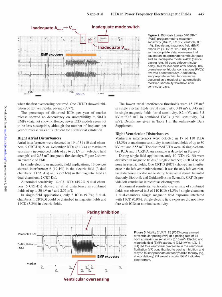
Provocation StudyExamples of provoked EMI are shown in Figures 2 and 3 and for atrial and ventricular interference, respectively.
At maximum sensitivity, no interference during EMF exposure occurred in 71 of 110 implanted devices (64.5%). The noise signal provoked inadequate ICD responses in 19 patients in the atrial channel and in 20 individuals in the ven-tricular channel (Figure 4).
Programmed at nominal sensitivity, no disturbance occurred in 91 of 110 devices (82.7%). In 14 of these 19 ICDs with EMF interference, the atrial channel was affected, whereas in 5 patients, interference occurred in the ventricular channel (Figure 4).
At interference thresholds, oversensing in both the atrial and ventricular channels was the type of the first sensing failure. None of the tested devices primarily switched into noise mode
Figure 1. Scheme of the technical test setup. The patient sat in the center of 2 coils (Helmholtz pair) in an upright position. For current injection, 4 electrodes were placed on the shoulder/neck of the patient, and 2 electrodes were placed on each leg. The system continuously monitored and recorded the patient’s surface ECG. Via a programming unit, the intracardiac electrograms were monitored and printed continuously during electromagnetic field exposure. ICD indicates implantable cardioverter-defibrillator.
by guest on June 1, 2018http://circ.ahajournals.org/
Dow
nloaded from
Napp et al ICDs in Power Frequency Electromagnetic Fields 445
when the first oversensing occurred. One CRT-D showed inhi-bition of left ventricular pacing (P077).
The percentage of disturbed ICDs per year of market release showed no dependency on susceptibility to 50-Hz EMFs (data not shown). Hence, newer ICD models seem not to be less susceptible, although the number of implants per year of release was not sufficient for a statistical validation.
Right Atrial DisturbancesAtrial interferences were detected in 19 of 31 (10 dual-cham-bers; 9 CRT-Ds) 2- or 3-chamber ICDs (61.3%) at maximum sensitivity in combined fields of up to 30 kV·m−1 (electric field strength) and 2.55 mT (magnetic flux density). Figure 2 shows an example of EMI.
In single electric or magnetic field applications, 13 devices showed interference: 6 (19.4%) in the electric field (3 dual chambers; 3 CRT-Ds) and 7 (22.6%) in the magnetic field (5 dual-chambers; 2 CRT-Ds).
At nominal sensitivity, 14 of 31 ICDs (45.2%; 9 dual-cham-bers; 5 CRT-Ds) showed an atrial disturbance in combined fields of up to 30 kV·m−1 and 2.55 mT.
In single-field applications, only 3 ICDs (9.7%; 2 dual-chambers; 1 CRT-D) could be disturbed in magnetic fields and 1 ICD (3.2%) in electric fields.
The lowest atrial interference thresholds were 15 kV·m−1 in single electric fields (atrial sensitivity, 0.18 mV), 0.45 mT in single magnetic fields (atrial sensitivity, 0.2 mV), and 3.5 kV·m−1/0.3 mT in combined EMFs (atrial sensitivity, 0.4 mV). Details are given in Table I in the online-only Data Supplement.
Right Ventricular Disturbances Ventricular interferences were detected in 17 of 110 ICDs (15.5%) at maximum sensitivity in combined fields of up to 30 kV·m−1 and 2.55 mT. The disturbed ICDs were 16 single-cham-ber ICDs and 1 CRT-D. An example is depicted in Figure 3.
During single-field application, only 10 ICDs (9.1%) were disturbed in magnetic fields (8 single-chamber; 2 CRT-Ds) and none in electric fields. One CRT-D (P077) showed an interfer-ence in the left ventricular channel. It was the only left ventricu-lar disturbance elicited in the study; however, it should be noted that only Biotronik and Guidant/Boston Scientific CRT-Ds pro-vide left ventricular intracardiac electrograms.
At nominal sensitivity, ventricular oversensing of combined fields was observed in 5 of 110 ICDs (4.5%; 4 single-chamber; 1 dual-chamber). Single magnetic field exposure interfered with 1 ICD (0.9%). Single electric field exposure did not inter-fere with ICDs at nominal sensitivity.
Figure 2. Biotronik Lumax 540 DR-T (P085) programmed to maximum sensitivity (atrium, 0.2 mV; ventricle, 0.5 mV). Electric and magnetic field (EMF) exposure (30 kV*m-1/1.8 mT) led to an inappropriate atrial oversense that caused an inappropriate ventricular pace and an inadequate mode switch (device pacing rate, 45 bpm; atrioventricular delay, 150 milliseconds after sense). The premature ventricular contractions (PVCs) evolved spontaneously. Additionally, inappropriate ventricular oversense occurred as a result of an automatically modified sensitivity threshold after ventricular pace.
Figure 3. Vitality 2 VR T175 (P063) programmed at ventricular pacing (VVI) at a pacing rate of 75 bpm at maximum sensitivity (0.18 mV). Electric and magnetic field (EMF) exposure (25.5 kV*m-1/2.15 mT) led to a ventricular oversense in the ventricular fibrillation (VF) zone that led to pacing inhibition and maybe to inappropriate antitachycardia therapy (eg, shock delivery) if it would sustain. EGM indicates electrogram.
by guest on June 1, 2018http://circ.ahajournals.org/
Dow
nloaded from

446 Circulation January 28, 2014
The lowest ventricular interference thresholds were >2.55 mT in single electric fields, 0.6 mT in single magnetic fields (ventricular sensitivity, 0.18 mV), and 16.4 kV·m−1/1.8 mT in combined EMFs (ventricular sensitivity, 0.18 mV). Details are given in Table II in the online-only Data Supplement.
Interference Thresholds in Relation to Limit ValuesThe interference thresholds of the disturbed ICDs at maxi-mum and nominal sensitivity within the range of the limit values set by the European Union and the ANSI/Institute of Electrical and Electronics Engineers (IEEE; Table 1) are shown in Figure 5.
At maximum sensitivity, 39 ICDs could be disturbed in single and combined fields up to the tested limits (30 kV·m−1/2.55 mT). Of these, no interference occurred within the limit values set by the European Union for the general public, and only 1 device could be disturbed within the set occupational limits.
With respect to the limits defined by the ANSI/IEEE C95.6 guideline, the interference thresholds of 3 ICDs with atrial interference and 1 ICD with ventricular interference were in the range for the general public. Within the occupational limits of this guideline, the ICDs of 21 patients could be dis-turbed: 10 atrial and 11 ventricular disturbances respectively.
Focusing on nominal sensitivity, 19 ICDs could be disturbed within tested limits; of these, 3 ICDs with atrial interference were within the limits of the ANSI/IEEE C95.6 guideline for general public, and 6 ICDs were within the limits for occupa-tional exposure (4 atrial and 2 ventricular disturbances). At nominal sensitivity, no interference could be elicited within the European Union limit values in either the general public or the occupational limits.
DiscussionThe main findings of the present study are (see also Table 4) as follows:
1. Interference of EMFs with ICDs occurred in 17.3% at pro-grammed nominal sensitivity and in 35.5% at maximum sensi-tivity within the tested limits.
2. Interference of EMFs with the ventricular channel occurred in 4.5% of ICDs at nominal sensitivity and in 15.5% at maximum sensitivity.
3. EMF interference with the atrial channel occurred in 45.2% at nominal sensitivity and in 61.3% at maximum sensitivity.
4. No interference occurred within the European Union limit val-ues set for the general public, and only 1 device could be dis-turbed in the atrial channel within the occupational limits.
5. Within the limit values of the United States (ANSI/IEEE), EMI with the atrial and the ventricular channel occurred in 4% (general public limits) and 19% (occupational limits) of all patients.
6. Active pacing of the ventricle increased the susceptibility to EMI by 91% of all tested ICDs.
The EMF-Portal (www.emf-portal.org), the most compre-hensive scientific literature database on the effects of EMFs, currently reveals ≈300 publications on EMI with cardiac implants. Although 189 studies have investigated EMI in the low-frequency range (including direct current), only 47 publications have dealt with the power frequency range (50/60 Hz). However, many of these 47 publications were conducted on various numerical and physical models (eg, see References 22–26). Additionally, there have been a number of case studies (eg, References 27 and 28) or retro-spective observational studies (eg, References 29 and 30). Another group of publications comprises investigations on EMI caused by medical electrical equipment working in the 50/60-Hz range.31–33 Even though the first evidence of EMI appeared in the early 1960s,1 to date, there have been only 4 clinical studies21,34–36 with patients bearing a cardiac implant under standardized or controlled exposure condi-tions in the 50/60-Hz power frequency range. Nevertheless, provocation studies were recommended in numerous pre-vious studies.24,33,35,37 Trigano and coworkers34 showed in a large in vivo study of cardiac pacemaker patients that single magnetic fields pulsed at power frequency are able to cause an inappropriate mode switch and pacing inhibition in uni-polar lead configuration. Bipolar sensing seemed to be rather safe in magnetic fields with a flux density of up to 100 µT. Recently, Tiikkaja and coworkers36 investigated interference thresholds of cardiac pacemakers and ICDs at extremely low-frequency EMFs, but only in a small number of vol-unteers (13 ICD patients, 11 cardiac pacemaker patients) at magnetic flux densities not higher than 300 µT and not considering combined magnetic and electric exposure. None of the previous studies considered worst-case conditions, for example, maximum sensitivity of devices or full inspiration (see Test Procedure).
The present study investigated EMI with ICDs in a large in vivo study under worst-case conditions. We determined the
Figure 4. Right atrial (RA) and right ventricular (RV) disturbances caused by single and combined electric and magnetic fields (EMFs). CRT-D indicates cardiac resynchronization therapy–defibrillator; and ICD, implantable cardioverter-defibrillator.
by guest on June 1, 2018http://circ.ahajournals.org/
Dow
nloaded from

Napp et al ICDs in Power Frequency Electromagnetic Fields 447
lowest interference thresholds of 110 ICD patients in single and combined 50-Hz EMFs of up to 30 kV·m−1 and 2.55 mT.
The determined thresholds also apply for 60 Hz, the power frequency in the Americas. Previous studies showed
that the susceptibility to EMI of cardiac implants is in the same range at 50/60 Hz.20,38 The limit values of the American National Standards Institute do not differ between 50 and 60 Hz (Table 1).
Figure 5. Determined interference thresholds of the implantable cardioverter-defibrillators are shown in relation to the limit values of European Union (EU) and American Nationals Standards Institute/Institute of Electrical and Electronics Engineers (ANSI/IEEE). The markers represent the interference thresholds of the 39 devices (maximum sensitivity, top) and the 19 devices (nominal sensitivity, bottom) that could be disturbed within the tested limits.
by guest on June 1, 2018http://circ.ahajournals.org/
Dow
nloaded from

448 Circulation January 28, 2014
The knowledge of these interference thresholds closes the gap in the current guidelines for limiting exposure of ICD wearers to EMFs. Our data provides evidence that ICD distur-bances do not occur within the limits values of the European Union for the general public (5 kV·m−1/0.1 mT). The first sensing failures were detected at stronger fields, and only 1 device could be disturbed in the atrial channel within the range of current European Union limit values for occupational exposure (10 kV·m−1/0.5 mT). However, new occupational guidelines are currently being discussed in the European Union parliament (up to 10 kV·m−1/6 mT at 50 Hz).8 Our data indicate that, should these limits come into action, ICD distur-bances are more likely to occur.
Right Atrial DisturbancesIn 19 of 31 patients (61.3%), an atrial oversensing was regis-tered in EMFs within the tested limits (30 kV·m−1/2.55 mT). The higher probability of EMF interference in the atrial chan-nel can be ascribed to the small intrinsic atrial signals with consecutively higher programmed atrial sensitivities and a corresponding poor signal-to-noise ratio in the atrium channel. Right atrial disturbances may lead to a scenario that potentially carries risks for patients; sustained oversensing can cause an inadequate mode switch to VVI(-R)/DDI(-R). If patients are in sinus rhythm, the asynchronous pacing mode may increase the risk for developing atrial fibrillation or pacemaker syndrome. The latter is caused by an atrioventricular dyssynchrony with subsequent loss of atrial contribution to ventricular diastolic filling and nonphysiological pressure waves. In case of chro-notropic incompetence in patients with sick sinus node with an implanted 2- or 3-chamber device, a mode switch from DDD-R to VVI/DDI without activation of rate response may lead to the loss of chronotropic competence. In case of a dual-chamber device and sinus bradycardia, a pacing-induced left bundle-branch block pattern of activation with subsequent mechanical dyssynchrony can potentially lead to a loss of physical capac-ity. In the case of isolated atrial oversensing, a spontaneous VT may be inadequately classified as supraventricular tachycardia. If a supraventricular tachycardia time-out is not programmed, no therapy would be delivered in case of VT.
Right Ventricular DisturbancesVentricular interferences caused by the field exposure were detected 20 times at maximum sensitivity and 5 times at
nominal sensitivity. Right ventricular disturbances may lead to an inadequate detection of VT/VF and subsequent antit-achycardia pacing or shock delivery. There is increasing evi-dence that inadequate shocks by themselves are associated with worse prognosis, although a clear cause-effect relation-ship has not yet been proven.39 Some devices interpret these signals, depending on the individual sensing algorithm, as an artificial noise (eg, short intervals <120–130 milliseconds are unlikely to be VF) and subsequently switch to a certain dis-turbance mode, which may be programmed at V00/D00/000. However, in this case, a spontaneous VT/VF episode cannot be detected. In cases of premature ventricular contractions or intrinsic heart rates higher than the programmed pacing rate of V00/D00, stimulation may lead to delivery of stimuli into the T wave, carrying the risk of VT/VF induction. This is not unlikely because strong EMFs occur mostly in occupational environments when the patient may be under physical stress and thus have an increased intrinsic heart rate and an overall higher likelihood of VT/VF occurrence (eg, because of isch-emia in coronary artery disease) and elevated serum catechol-amine levels.
Shorter or pulsed noise episodes may not trigger VT/VF detection and subsequent ICD therapy but may lead to pacing inhibition in patients with pacemaker dependency, which may cause symptomatic bradycardia or loss of resynchronization efficacy in CRT patients.
Worst-Case ConditionsIn Tables I and II in the online-only Data Supplement, worst-case conditions are shown for all interference thresholds determined.
In terms of the atrial channel, sustained pacing affected the interference thresholds in 15 of 41 runs (36.6%) under sin-gle or combined exposure. At full inspiration, the thresholds decreased in 5 of 41 runs (12.2%). Both conditions had an impact in 5 of 41 cases (12.2%).
For the ventricular channel, interference thresholds changed in 30 of 33 exposures (90.9%) during pacing. Respiration influenced the interference thresholds in only 1 patient (P095); sustained pacing had no impact. Thus, the results support the assumption of the influence of the worst-case conditions of full inspiration and sustained pacing.
Our results further confirm previously obtained data from pacemakers21 showing the influence of the programmable sen-sitivity on interference thresholds of ICDs. The susceptibility to EMI was coupled with the sensitivity settings, that is, the lower the sensitivity value, the lower the interference threshold of the ICD and vice versa (in the same patient). However, different patients with equal interference thresholds do not necessarily have the same sensitivity settings (Tables I and II in the online-only Data Supplement). The impact of the sensitivity values varies among manufacturers because of the manufacturer’s specific automatic adjustment of the sensitivity threshold. For example, when the ventricular disturbances of the Biotronik and St. Jude Medical single-chamber ICDs were compared, the data revealed that 4 of 26 tested Biotronik ICDs (15.4%) and 4 of 34 tested St. Jude Medical ICDs (11.8%) could be dis-turbed at sensitivity values of 0.5 and 0.2 mV, respectively.
Table 4. Number of Right Atrial and Right Ventricular Disturbances at Maximum and Nominal Sensitivity
Maximum Sensitivity Nominal Sensitivity
Single E Field
Single B Field
Combined E/B Field
Single E Field
Single B Field
Combined E/B Field
Right atrial disturbances, n (%)
6 (19) 7 (23) 19 (61) 1 (3) 3 (10) 14 (45)
Right ventricular disturbances, n (%)
0 (0) 10 (9) 17 (15) 0 (0) 1 (1) 5 (5)
E indicates electric; and B, magnetic.
by guest on June 1, 2018http://circ.ahajournals.org/
Dow
nloaded from
Napp et al ICDs in Power Frequency Electromagnetic Fields 449
The susceptibility to EMI of an ICD is also influenced by the type of lead and the patient’s physique.18,21 Table III in the online-only Data Supplement gives details of the leads and patient physique for all patients.
Potential Clinical Implications and Clinical ManagementIt is important to identify patients at risk of EMI. If strong EMF exposure is expected, particular care must be taken to optimize the implantation procedure (maximum achievable P/R potential). An ICD test with low-sensitivity settings has to be considered. Moreover, regular control of the intrinsic signal amplitudes (P/R wave) and the occurrence of EMIs via tele-medicine transmitter is advisable.
It is not possible to define general sensitivity settings for EMF protection because of several individual factors, includ-ing lead position, patient physique, and type of EMF source. It remains a challenge for physicians to find a sensitivity level that gives a good balance between reduced EMI and accurate VT/VF sensing.
When inappropriate ICD discharges or episodes of EMI occur, patients should be assessed carefully. The situation of EMI occurrence should clearly be evaluated. Sometimes onsite measurements of EMFs are necessary. In terms of mini-mal device sensitivity, adjustment should be combined with ICD testing. Furthermore, patients should be tested in simu-lated EMFs, as in the present study.
In case of suddenly perceiving interference, increasing the distance to sources of EMF is the first remedial action to stop the dysfunction. Device defects caused by low-frequency EMFs have not yet been documented.
Study LimitationsThe present study was not designed to classify specific ICD models concerning their susceptibility in EMF exposure situ-ations. However, further investigations may identify patient-, device-, and lead-related predictors of EMI.
Dual-chamber ICDs and CRT-Ds are underrepresented in this study. Therefore, conclusions on atrial interferences are not based on as many patients as for the right ventricular lead. In addition, the uneven distribution of the number of implants from each manufacturer may have influenced the results.
The validation of the electric field generation is based on a method comparison with 6 volunteers (see the online-only Data Supplement for details). Although the results indicate good agreement between the 2 methods, the data should be validated with a larger number of volunteers.
Furthermore, the findings of this study cannot be transferred to EMI at intermediate frequency and radiofrequency. Finally, the data are not applicable to pacemakers because of the dif-ference in signal analysis of pacemakers and ICDs. Further study focusing on pacemaker patients is necessary.
ConclusionsThe findings indicate that extremely low-frequency EMFs of everyday life do not disturb sensing capabilities of ICDs. The limit values for the protection of humans exposed to EMFs in general public assume to protect patients with ICDs at 50/60 Hz. In contrast, strong electric, magnetic, or combined fields
in certain occupational environments are capable of causing undersensing or inappropriate sensing of atrial/ventricular tachyarrhythmias. However, a correct device function can still be expected in most cases. ICD devices with atrial sensing are more susceptible to EMI than single-chamber systems. Pacing in the ventricle increases the susceptibility to EMI.
In case of uncertainty about EMI, in vivo provocation examination such as those described in this study can provide a reliable and individual risk assessment for patients with implanted devices.
AcknowledgmentsWe thank the volunteers who participated in this study and the EMF-Portal team for the valuable contribution on the current status of pub-lications on this topic and their editorial input to this manuscript.
Source of FundingThis study was funded through a grant from the German Social Accident Insurance Institution for the energy, textile, electrical, and media products sectors (BG ETEM) and the research unit for electro-pathology (FFE).
DisclosuresDrs Napp and Zink received travel grants from Biotronik, Boston Scientific, Medtronic, and St. Jude Medical. Drs Knackstedt, Bellmann, Marx, and Schauerte have received funding from Biotronik, Boston Scientific, Medtronic, and St. Jude Medical for consulting and lectures. The other authors report no conflicts.
References 1. Furman S, Parker B, Krauthamer M, Escher DJ. The influence of electro-
magnetic environment on the performance of artificial cardiac pacemak-ers. Ann Thorac Surg. 1968;6:90–95.
2. Brugada J, Vardas P, Wolpert C. The EHRA White Book 2008: The Current Status of Cardiac Electrophysiology in ESC Member Countries. http://www.escardio.org/communities/EHRA/publications/Pages/white-book-project.aspx. 2008;123–131. Accessed April 4, 2013.
3. Auricchio A, Kuck KH, Hatala R, Arribas F. The EHRA White Book 2013: The Current Status of Cardiac Electrophysiology in ESC Member Countries. http://www.escardio.org/communities/EHRA/publications/Pages/white-book-project.aspx. 2013;181–190. Accessed April 4, 2013.
4. Institute for Applied Quality Improvement and Research in Health Care GmbH (AQUA). German Hospital Quality Report 2011. http://www.sqg.de/quality-report/index.html. 2012;53–58. Accessed April 4, 2013.
5. Daubert JP, Zareba W, Cannom DS, McNitt S, Rosero SZ, Wang P, Schuger C, Steinberg JS, Higgins SL, Wilber DJ, Klein H, Andrews ML, Hall WJ, Moss AJ; MADIT II Investigators. Inappropriate implantable cardioverter-defibrillator shocks in MADIT II: frequency, mechanisms, predictors, and survival impact. J Am Coll Cardiol. 2008;51:1357–1365.
6. Council of the European Union (CONSILIUM). Council recommendation of 12 July 1999 on the limitation of exposure of the general public to elec-tromagnetic fields (0 Hz to 300G Hz). Official Journal of the European Communities. Brussels, Belgium; 1999. 1999/519/EC.
7. Council of the European Union (CONSILIUM). Corrigendum to Directive 2004/40/EC of the European Parliament and of the Council of 29 April 2004 on the minimum health and safety requirements regarding the expo-sure of workers to the risks arising from physical agents (electromagnetic fields). Official Journal of the European Communities. Brussels, Belgium; 2004. 2004/40/EC.
8. Council of the European Union (CONSILIUM). Proposal for a Directive of the European Parliament and of the Council on the minimum health and safety requirements regarding the exposure of workers to the risks aris-ing from physical agents (electromagnetic fields). Official Journal of the European Communities. Brussels, Belgium; 2012. 14020/12.
9. IEEE Standards Association (IEEE-SA). IEEE standard for safety levels with respect to human exposure to electromagnetic fields, 0-3k Hz. New York, NY: The Institute of Electrical and Electronics Engineers; 2002. C95.6-2002.
by guest on June 1, 2018http://circ.ahajournals.org/
Dow
nloaded from

450 Circulation January 28, 2014
10. International Commission on Non-Ionizing Radiation Protection (ICNIRP). Guidelines for limiting exposure to time-varying electric and magnetic fields (1 Hz to 100k Hz). Health Phys. 2010;99:818–836.
11. European Committee for Electrotechnical Standardization (CENELEC). Active implantable medical devices - Part 2-2: Particular requirements for active implantable medical devices intended to treat tachyarrhyth-mia (includes implantable defibrillators). Central Secretariat. Brussels, Belgium; 2008. EN45502-2-2:2008.
12. International Organization for Standardization (ISO). Implants for sur-gery: active implantable medical devices, part 6: particular requirements for active implantable medical devices intended to treat tachyarrhythmia (including implantable defibrillators). ISO Standards Catalogue. Geneva, Switzerland; 2010. ISO14708-6:2010.
13. International Organization for Standardization (ISO). Active implantable medical devices: electromagnetic compatibility: EMC test protocols for implantable cardiac pacemakers, implantable cardioverter defibrillators and cardiac resynchronization devices. ISO Standards Catalogue. Geneva, Switzerland; 2012. ISO14117-2012.
14. American Nationals Standards Institute/Association for the Advancement of Medical Instrumentation (ANSI/AAMI). Active implantable medical devices - electromagnetic compatibility - EMC test protocols for implant-able cardiac pacemakers and implantable cardioverter defibrillators. Arlington; Association for the Advancement of Medical Instrumentation; 2007. ANSI/AAMI PC69:2007.
15. Berufsgenossenschaft Energie Textil Elektro Medienerzeugnisse (BG ETEM). Unfallverhütungsvorschrift Elektromagnetische Felder. Hauptverwaltung. Koeln; 2002. BGV B11-6.01.
16. Deutsche Elektrotechnische Kommission im DIN und VDE. Betrieb von elektrischen Anlagen: Teil 100: Allgemeine Festlegungen. VDE-Verlag. Berlin, Germany; 2009. DIN VDE 0105-100:2009.
17. Deno DW. Currents induced in the human body by high voltage transmis-sion line field-measurement and calculation of distribution and dose. IEEE Transactions on Power Apparatus and Systems, 1977;PAS-96:1517–1527.
18. Joosten S, Pammler K, Silny J. The influence of anatomical and physi-ological parameters on the interference voltage at the input of unipolar cardiac pacemakers in low frequency electric fields. Phys Med Biol. 2009;54:591–609.
19. Bolz T, Bahr A, Gustrau F, Eichhorn KF, Hille S, Hentschel K. Modeling of bipolar electrodes configurations of a cardiac pacemaker (10 Hz to 1 MHz). Bundesanstalt fuer Arbeitsschutz und Arbeitsmedizin. Dortmund, Germany; 2009. Project F 2090-2009.
20. Scholten A, Silny J. The interference threshold of cardiac pacemakers in electric 50 Hz fields. J Med Eng Technol. 2001;25:1–11.
21. Toivonen L, Valjus J, Hongisto M, Metso R. The influence of elevated 50 Hz electric and magnetic fields on implanted cardiac pacemakers: the role of the lead configuration and programming of the sensitivity. Pacing Clin Electrophysiol. 1991;14:2114–2122.
22. Babouri A, Hedjeidj A, Guendouz L. Experimental and theoretical inves-tigation of implantable cardiac pacemaker exposed to low frequency mag-netic field. J Clin Monit Comput. 2009;23:63–73.
23. Caputa K, Dimbylow PJ, Dawson TW, Stuchly MA. Modelling fields induced in humans by 50/60 Hz magnetic fields: reliability of the results and effects of model variations. Phys Med Biol. 2002;47:1391–1398.
24. Scholten A, Joosten S, Silny J. Unipolar cardiac pacemakers in elec-tromagnetic fields of high voltage overhead lines. J Med Eng Technol. 2005;29:170–175.
25. Scholten A, Silny J. The interference threshold of unipolar cardiac pace-makers in extremely low frequency magnetic fields. J Med Eng Technol. 2001;25:185–194.
26. Gustrau F, Bahr A, Goltz S, Eggert S. Active medical implants and occu-pational safety: measurement and numerical calculation of interference voltage. Biomed Tech (Berl). 2002;47(suppl 1 pt 2):656–659.
27. Pai RK, Abedin M, Rawling DA. Inappropriate ICD shocks for inappro-priate reasons. Indian Pacing Electrophysiol J. 2008;8:69–71.
28. Chongtham DS, Bahl A, Kumar RM, Talwar KK. Inappropriate shock delivery by implantable cardioverter defibrillator due to electrical interfer-ence with washing machine. Int J Cardiol. 2007;118:e44–e45.
29. Rauwolf T, Guenther M, Hass N, Schnabel A, Bock M, Braun MU, Strasser RH. Ventricular oversensing in 518 patients with implanted cardiac defibrilla-tors: incidence, complications, and solutions. Europace. 2007;9:1041–1047.
30. Kolb C, Zrenner B, Schmitt C. Incidence of electromagnetic interference in implantable cardioverter defibrillators. Pacing Clin Electrophysiol. 2001;24(pt 1):465–468.
31. Roedig JJ, Shah J, Elayi CS, Miller CS. Interference of cardiac pacemaker and implantable cardioverter-defibrillator activity during electronic dental device use. J Am Dent Assoc. 2010;141:521–526.
32. Guertin D, Faheem O, Ling T, Pelletier G, McComas D, Yarlagadda RK, Clyne C, Kluger J. Electromagnetic interference (EMI) and arrhythmic events in ICD patients undergoing gastrointestinal procedures. Pacing Clin Electrophysiol. 2007;30:734–739.
33. Garofalo RR, Ede EN, Dorn SO, Kuttler S. Effect of electronic apex loca-tors on cardiac pacemaker function. J Endod. 2002;28:831–833.
34. Trigano A, Blandeau O, Souques M, Gernez JP, Magne I. Clinical study of interference with cardiac pacemakers by a magnetic field at power line frequencies. J Am Coll Cardiol. 2005;45:896–900.
35. Souques M, Magne I, Lambrozo J. Implantable cardioverter defibrillator and 50- Hz electric and magnetic fields exposure in the workplace. Int Arch Occup Environ Health. 2011;84:1–6.
36. Tiikkaja M, Aro AL, Alanko T, Lindholm H, Sistonen H, Hartikainen JE, Toivonen L, Juutilainen J, Hietanen M. Electromagnetic interference with cardiac pacemakers and implantable cardioverter-defibrillators from low-frequency electromagnetic fields in vivo. Europace. 2013;15:388–394.
37. Tiikkaja M, Alanko T, Lindholm H, Hietanen M, Toivonen L, Hartikainen J. Interference of low frequency magnetic fields with implantable cardio-verter-defibrillators. Scand Cardiovasc J. 2012;46:308–314.
38. Irnich W. Interference of implantable pacemakers and defibrillators: fun-damentals. Herzschr Elektrophys. 2004;15:9–21.
39. van Rees JB, Borleffs CJ, de Bie MK, Stijnen T, van Erven L, Bax JJ, Schalij MJ. Inappropriate implantable cardioverter-defibrillator shocks: incidence, predictors, and impact on mortality. J Am Coll Cardiol. 2011;57:556–562.
CLINICAL PERSPECTIVETo date, reliable systematic data on electromagnetic interferences on implantable cardioverter-defibrillators are scarce despite a high potential clinical relevance. Current recommendations by the manufacturers are very conservative with respect to expo-sure of implantable cardioverter-defibrillator patients to electric and magnetic fields (EMFs). This is based on the assumption that EMFs may lead to harmful interferences with the device. Recommendations on the code of behavior on how to handle electric and magnetic field sources in everyday life are inconsistent and are not based on in vivo studies. Decision making for implantable cardioverter-defibrillator implantation for the primary prevention in job-related EMF-exposed patients and subse-quent recommendation of early retirement is often complex. National and international guidelines for the protection of humans exposed to EMF exclude patients wearing electric cardiac implants. The present study shows that electromagnetic interferences occur predominantly in relatively strong EMFs, which are normally present only in occupational environments. Moreover, we demonstrate a strong dependency on the programmed sensitivity of the device. Additionally, our data suggest that individual thresholds of electromagnetic interferences can be obtained and compared with the individual exposure of the patient. These results are important for clinicians to optimize the implantation procedure to achieve maximum obtainable intracardiac electro-gram potentials, to choose appropriate device programming, and to provide advice for the management of patients with foresee-able high EMF exposure. Nonetheless, further investigations are needed to investigate patient- and device-related predictors of electromagnetic interferences. This may help to develop better sensing algorithms and to design new implantable cardioverter-defibrillator leads for the prevention of harmful electromagnetic interferences of implantable cardioverter-defibrillators.
by guest on June 1, 2018http://circ.ahajournals.org/
Dow
nloaded from

Barbara Bellmann, Nikolaus Marx, Patrick Schauerte and Jiri SilnyAndreas Napp, Stephan Joosten, Dominik Stunder, Christian Knackstedt, Matthias Zink,
Frequency: An In Vivo StudyElectromagnetic Interference With Implantable Cardioverter-Defibrillators at Power
Print ISSN: 0009-7322. Online ISSN: 1524-4539 Copyright © 2013 American Heart Association, Inc. All rights reserved.
is published by the American Heart Association, 7272 Greenville Avenue, Dallas, TX 75231Circulation doi: 10.1161/CIRCULATIONAHA.113.003081
2014;129:441-450; originally published online October 25, 2013;Circulation.
http://circ.ahajournals.org/content/129/4/441World Wide Web at:
The online version of this article, along with updated information and services, is located on the
http://circ.ahajournals.org/content/suppl/2013/10/25/CIRCULATIONAHA.113.003081.DC1Data Supplement (unedited) at:
http://circ.ahajournals.org//subscriptions/
is online at: Circulation Information about subscribing to Subscriptions:
http://www.lww.com/reprints Information about reprints can be found online at: Reprints:
document. Permissions and Rights Question and Answer this process is available in the
click Request Permissions in the middle column of the Web page under Services. Further information aboutOffice. Once the online version of the published article for which permission is being requested is located,
can be obtained via RightsLink, a service of the Copyright Clearance Center, not the EditorialCirculationin Requests for permissions to reproduce figures, tables, or portions of articles originally publishedPermissions:
by guest on June 1, 2018http://circ.ahajournals.org/
Dow
nloaded from

1
SUPPLEMENTAL MATERIAL
Supplemental Methods
As stated in the manuscript the induced current in the thorax by exogenous electric fields can
be reproduced by direct current injection. For validation we conducted a test with 6 volunteers
applying real electric field exposure as well as direct current injection and compared the
induced voltage in the body.
The test was performed in the high voltage laboratory of the Institute for High Voltage
Technology at the RWTH Aachen University. We generated a real electric field with a special
high voltage electrode (O-shape, diameter 3 m). The electrode was connected to 50 Hz AC
voltage in order to create an environmental equivalent vertically oriented electric field as it
occurs e.g. under power lines.
Moreover 4 electrodes were placed on the shoulder/neck of the volunteers to directly supply
50 Hz AC currents as we did in the present study. Also 2 electrodes were placed on each leg.
With these electrodes the body current due to field induction, as well as direct injection, was
measured.
The two methods - real field exposure and direct current injection - were compared on the
basis of measurements in the body. Through esophagus catheters with sensing electrodes, the
induced voltage close to the apex of the right ventricle, was measured. Details about this
procedure can be found elsewhere.1

2
The volunteers were exposed for 30 seconds to different electric fields: 1 kV/m, 4 kV/m, 8
kV/m and 12 kV/m. The field strength was controlled as well as the induced body current and
the induced voltage was recorded continuously. In the same setting subsequent to real field
exposure, the direct current injection measurements were performed while AC currents of 40
μA und 90 μA were applied.
To compare the induced voltages of the measurement series the averaged peak value is
calculated and normalized to the particular body current. In Figure S1 the results are shown
for real field exposure and direct current injection. Depicted are the minimum, mean and
maximum values of the measurements. The variations are caused due to the nonlinear relation
between the body current and the induced voltage, as well as body movements, like
swallowing and muscle contractions. However, the results of the two methods are in the same
range, so therefore we conclude that direct current injection is a valid reproduction of real
electric field exposure.

3
Supplemental Tables
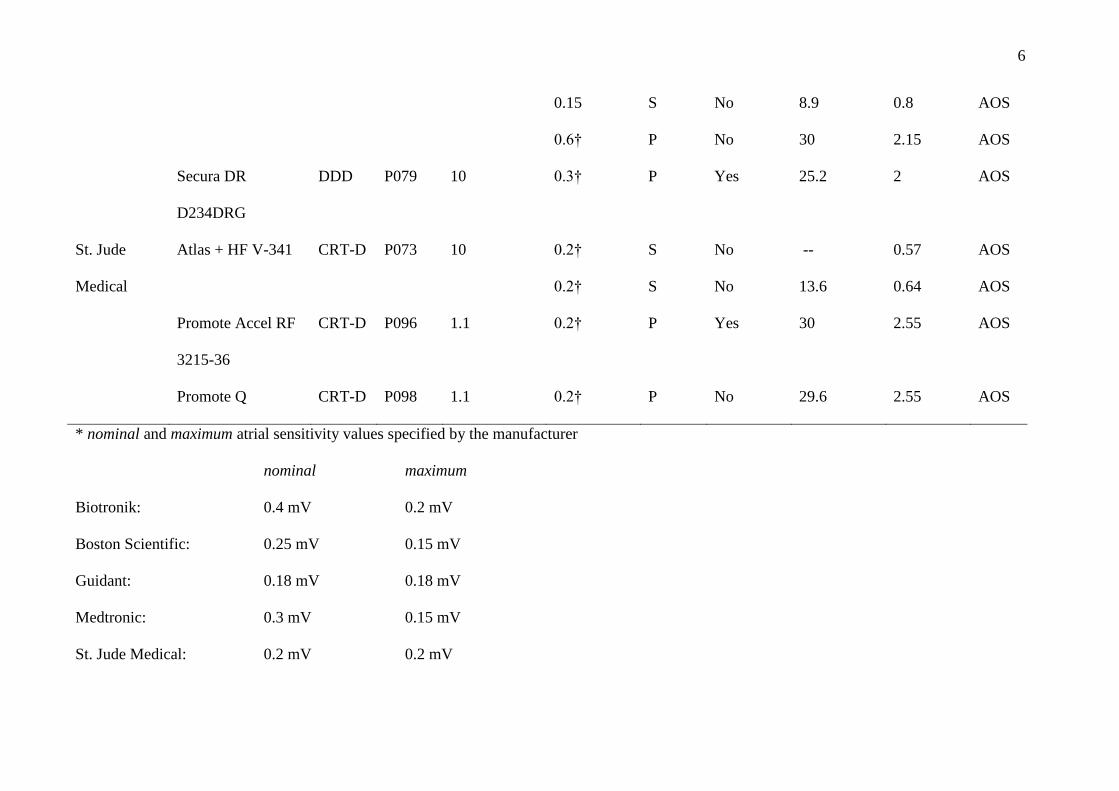
Table I. Interference of EMF with the atrial channel.
As explanation e.g. patient 36: The interference threshold of the patient’s Medtronic Consult CRT-D D234TRK was 30 kV/m in a single electric
field and 2.55 mT in a single magnetic field at maximum sensitivity (0.15 mV). Combined electric and magnetic fields the CRT-D could be
disturbed at 8.5 kV/m and 1.4 mT at maximum sensitivity. At nominal sensitivity (0.3 mV) no interference occurred under single field application,
however in combined fields the interference threshold was found at 30 kV/m and 2.55 mT.
Manu-
facturer
Model
Pacing
mode
Patient
Atrium lead
(tip/ring
space) [mm]
Worst-case conditions Single/Combined
interference thresholds
Dys-
func-
tion§
Atrium
sensitivity*
[mV]
Mode‡
Full inspi-
ration
E field
[kVm-1
]
B field
[mT]
Biotronik Lexos DR-T DDD P017 10 0.2 S No 30 1.8 AOS
Lumax 300 DR-T DDD P064 10 0.2
0.4†
P
P
No
Yes
21.5
27.1
2.15
2.55
AOS
AOS
Lumax 540 DR-T DDD P085 10 0.2
0.4†
S
P
No
Yes
30
27.4
1.4
2.55
AOS
AOS
Lumax 540 DR-T DDD P091 10 0.2 S No -- 0.45 AOS

4
0.2
0.4†
0.4†
P
S
S
No
No
No
3.5
--
14
0.3
0.64
0.45
AOS
AOS
AOS
Guidant /
Boston
Scientific
Ventak Prizm 2 DR
1861
DDD P050 17.8 0.18† S No 25.9 2.15 AOS
Vitality2 T165DR DDD P056 17.8 0.18†
0.18†
0.18†
S
S
P
No
No
No
15
--
12
--
0.8
0.64
AOS
AOS
AOS
Teligen 100 F110 DDD P105 10 0.15
0.25†
P
P
Yes
No
9
9
1.2
1.4
AOS
AOS
Medtronic Consulta CRT-D
D234TRK
CRT-D P036 10 0.15
0.15
0.15
0.3†
S
S
S
S
No
No
No
No
30
--
8.5
30
--
2.55
1.4
2.55
AOS
AOS
AOS
AOS
Consulta CRT-D CRT-D P069 10 0.15 S No 24.6 -- AOS

5
D234TRK 0.15 P No 16.5 1.8 AOS
Consulta CRT-D
D234TRK
CRT-D P099 10 0.15 P No 18.2 1.6 AOS
InSync III Marquis
7279
CRT-D P070 10 0.15
0.15
S
S
No
No
25.6
21.1
--
1.8
AOS
AOS
InSync Maximo
7304
CRT-D P072 10 0.15 S No 23 1.8 AOS
InSync Sentry 7298 CRT-D P002 17.8 0.15† P No 28 1 AOS
Intrinsic 7288 DDD P026 10 0.15
0.15
0.15
0.45†
S
S
S
P
No
No
No
No
19.5
--
7.4
25
--
2.35
1.8
1.8
AOS
AOS
AOS
AOS
Protecta DR
D364DRG
DDD P092 10 0.15
0.15
0.15
S
S
S
No
No
No
23
--
10.5
--
1.9
1.1
AOS
AOS
AOS
Protecta XT-DR DDD P103 8 0.15 S No -- 0.94 AOS
6
0.15
0.6†
S
P
No
No
8.9
30
0.8
2.15
AOS
AOS
Secura DR
D234DRG
DDD P079 10 0.3† P Yes 25.2 2 AOS
St. Jude
Medical
Atlas + HF V-341 CRT-D P073 10 0.2†
0.2†
S
S
No
No
--
13.6
0.57
0.64
AOS
AOS
Promote Accel RF
3215-36
CRT-D P096 1.1 0.2† P Yes 30 2.55 AOS
Promote Q CRT-D P098 1.1 0.2† P No 29.6 2.55 AOS
* nominal and maximum atrial sensitivity values specified by the manufacturer
nominal maximum
Biotronik: 0.4 mV 0.2 mV
Boston Scientific: 0.25 mV 0.15 mV
Guidant: 0.18 mV 0.18 mV
Medtronic: 0.3 mV 0.15 mV
St. Jude Medical: 0.2 mV 0.2 mV

7
† nominal sensitivity (preset sensitivity programmed by the treating physician)
‡ P: exposure during sustained pacing - S: exposure during intrinsic heart rate
§ AOS: atrial over sense

8
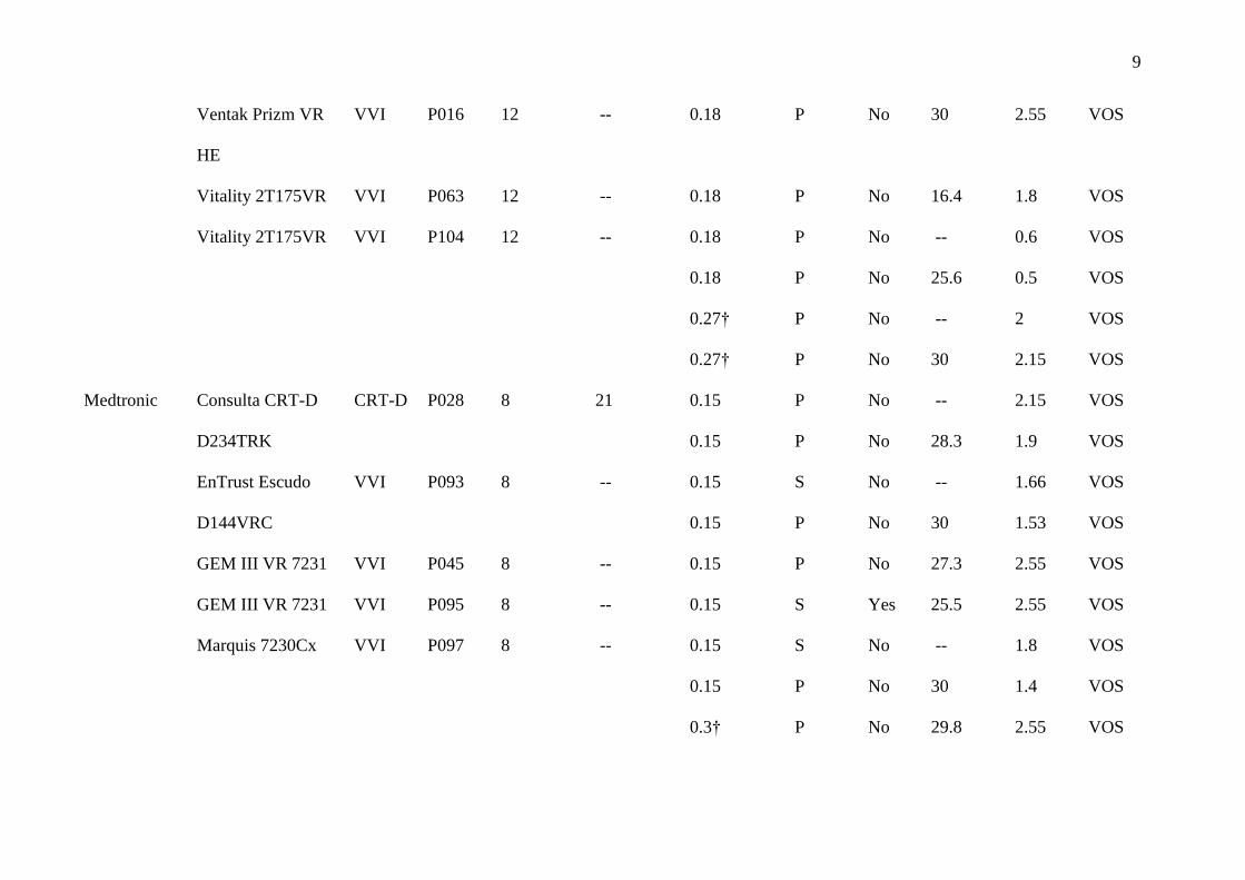
Table II. Interference of EMF with the ventricular channel.
Manu-
facturer
Model
Pacing
mode
Patient
Lead (tip/ring space)
[mm]
Worst-case conditions Single/Combined
interference
thresholds
Dys-
func-
tion§
Ventricle
sensitivity*
[mV]
Mode‡
Full
inspi-
ration
Right
ventricle
Left
ventricle
E field
[kVm-1
]
B field
[mT]
Biotronik Lexos VR-T VVI P043 9 -- 0.5 P No 26.8 2.55 VOS
Lexos VR-T VVI P066 9 -- 0.5 P No 27.1 2.55 VOS
Lumax 300 VR-T VVI P055 11.5 -- 0.5
0.5
0.8†
P
P
P
No
No
No
--
29.8
25.5
0.8
0.8
0.9
VOS
VOS
VOS
Lumax 300 HF-T CRT-D P077 11.5 18 0.5 (RV)
0.5 (LV)
P
No
No
--
--
--
2
LVI
Guidant /
Boston
Scientific
Ventak Prizm 2 VR VVI P076|| 12 -- 0.18 P No -- 1.8 VOS
9
Ventak Prizm VR
HE
VVI P016 12 -- 0.18 P No 30 2.55 VOS
Vitality 2T175VR VVI P063 12 -- 0.18 P No 16.4 1.8 VOS
Vitality 2T175VR VVI P104 12 -- 0.18
0.18
0.27†
0.27†
P
P
P
P
No
No
No
No
--
25.6
--
30
0.6
0.5
2
2.15
VOS
VOS
VOS
VOS
Medtronic Consulta CRT-D
D234TRK
CRT-D P028 8 21 0.15
0.15
P
P
No
No
--
28.3
2.15
1.9
VOS
VOS
EnTrust Escudo
D144VRC
VVI P093 8 -- 0.15
0.15
S
P
No
No
--
30
1.66
1.53
VOS
VOS
GEM III VR 7231 VVI P045 8 -- 0.15 P No 27.3 2.55 VOS
GEM III VR 7231 VVI P095 8 -- 0.15 S Yes 25.5 2.55 VOS
Marquis 7230Cx VVI P097 8 -- 0.15
0.15
0.3†
S
P
P
No
No
No
--
30
29.8
1.8
1.4
2.55
VOS
VOS
VOS

10
* nominal and maximum ventricular sensitivity values specified by the manufacturer
Maximo VR 7232 VVI P029 8 -- 0.15
0.3†
P
P
No
No
21.3
25.6
1.4
1.4
VOS
VOS
Maximo VR 7232 VVI P053 8 -- 0.15 P No 30 2.55 VOS
Protecta DR
D364DRG
DDD P092 8 -- 0.3† P No 16.7 1.8 VOS
Virtuoso VR
D164VWC
VVI P088 8 -- 0.15 P No 30 2.3 VOS
St. Jude
Medical
Atlas+ VR V-193 VVI P033|| 11 -- 0.2 P No -- 1.4 VOS
Atlas+ VR V-193 VVI P065 11 -- 0.2
0.2
P
P
No
No
--
29.9
2
2.15
VOS
VOS
Atlas+ VR V-193 VVI P068 11 -- 0.2 P No 21 2.15 VOS
Atlas II VR V-168 VVI P102 11 -- 0.2
0.2
P
P
No
No
--
29.9
2.55
2.55
VOS
VOS

11
nominal maximum
Biotronik: RV 0.8 mV/LV 1.6 mV RV 0.5mV/LV 0.5 mV
Boston Scientific: RV 0.6 mV RV 0.15 mV
Guidant: RV 0.27 mV/LV 1.24 mV RV 0.18 mV/LV 0.62 mV
Medtronic: RV 0.3 mV RV 0.15mV
St. Jude Medical: RV 0.3 mV RV 0.2 mV
† nominal sensitivity (preset sensitivity programmed by the treating physician)
‡ P: exposure during sustained pacing - S: exposure during intrinsic heart rate
§ VOS: ventricular over sense - LVI: left ventricular inhibition
|| Was not further tested under combined field settings due to time constraints of the patients.
12
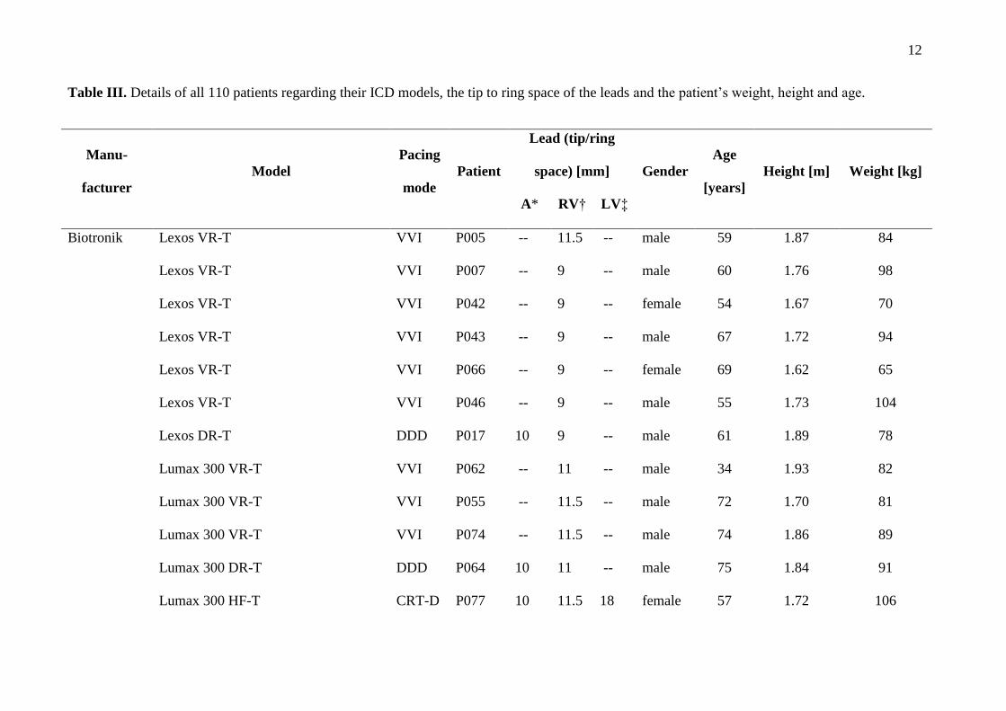
Table III. Details of all 110 patients regarding their ICD models, the tip to ring space of the leads and the patient’s weight, height and age.
Manu-
facturer
Model
Pacing
mode
Patient
Lead (tip/ring
space) [mm] Gender
Age
[years]
Height [m] Weight [kg]
A* RV† LV‡
Biotronik Lexos VR-T VVI P005 -- 11.5 -- male 59 1.87 84
Lexos VR-T VVI P007 -- 9 -- male 60 1.76 98
Lexos VR-T VVI P042 -- 9 -- female 54 1.67 70
Lexos VR-T VVI P043 -- 9 -- male 67 1.72 94
Lexos VR-T VVI P066 -- 9 -- female 69 1.62 65
Lexos VR-T VVI P046 -- 9 -- male 55 1.73 104
Lexos DR-T DDD P017 10 9 -- male 61 1.89 78
Lumax 300 VR-T VVI P062 -- 11 -- male 34 1.93 82
Lumax 300 VR-T VVI P055 -- 11.5 -- male 72 1.70 81
Lumax 300 VR-T VVI P074 -- 11.5 -- male 74 1.86 89
Lumax 300 DR-T DDD P064 10 11 -- male 75 1.84 91
Lumax 300 HF-T CRT-D P077 10 11.5 18 female 57 1.72 106

13
Lumax 340 VR-T VVI P021 -- 11 -- male 51 1.78 86
Lumax 340 VR-T VVI P083 -- 11 -- male 67 1.72 82
Lumax 340 HF CRT-D P060 10 11 female 69 1.57 62
Lumax 500 VR-T VVI P071 -- 9 -- male 60 1.90 121
Lumax 540 VR-T VVI P004 -- 11 -- male 31 1.84 84
Lumax 540 VR-T VVI P011 -- 9 -- male 73 1.74 83
Lumax 540 VR-T VVI P030 -- 11 -- male 49 1.80 105
Lumax 540 VR-T VVI P031 -- 11 -- male 65 1.86 99
Lumax 540 VR-T VVI P051 -- 11 -- male 62 1.68 62
Lumax 540 VR-T VVI P054 -- 11 -- male 73 1.80 93
Lumax 540 VR-T VVI P082 -- 11 -- male 71 1.78 73
Lumax 540 DR-T DDD P085 10 9 -- male 75 1.74 71
Lumax 540 DR-T DDD P091 10 11 -- male 52 1.75 105
Lumos VR-T VVI P009 -- 11.5 -- male 56 1.80 90
Guidant /
Boston
Prizm VR HE 1857 VVI P058 -- 12 -- female 53 1.75 100
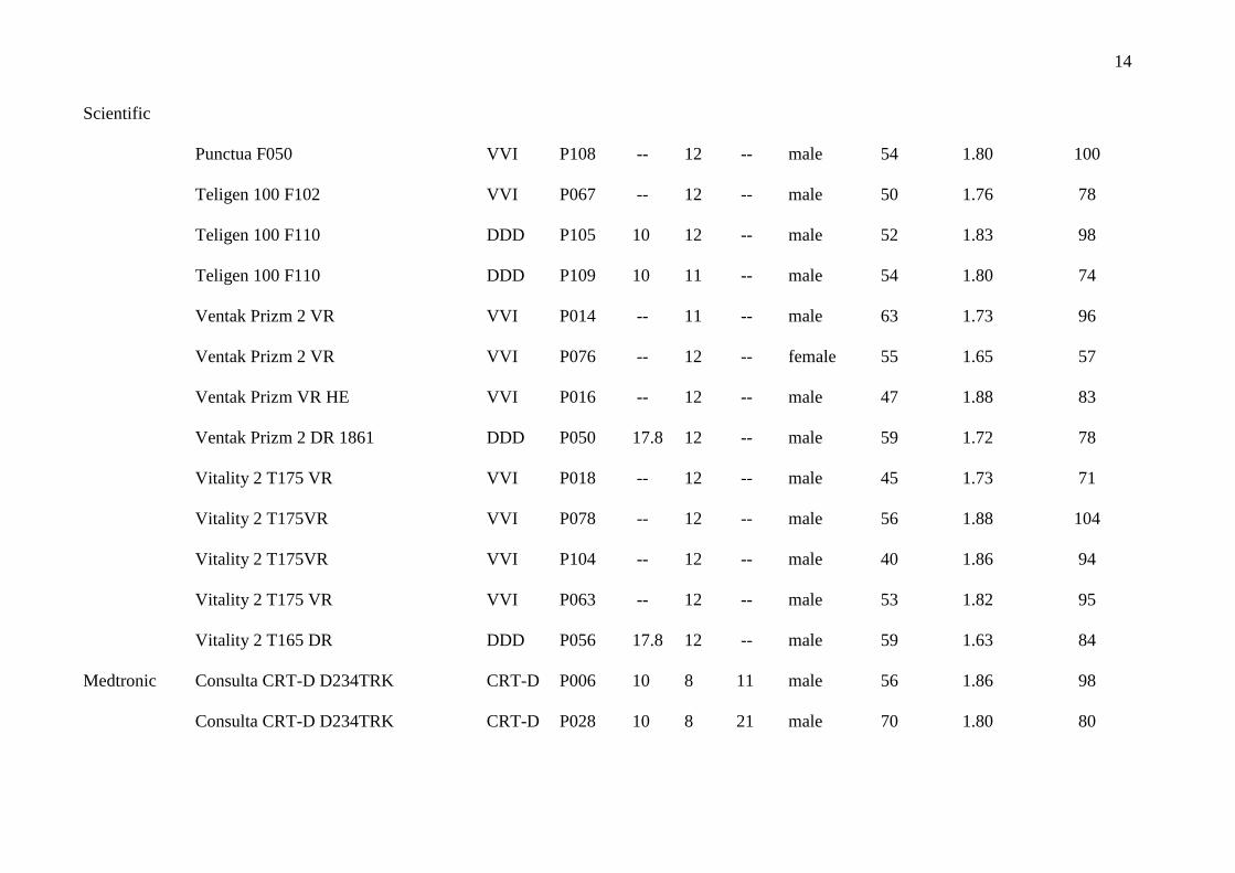
14
Scientific
Punctua F050 VVI P108 -- 12 -- male 54 1.80 100
Teligen 100 F102 VVI P067 -- 12 -- male 50 1.76 78
Teligen 100 F110 DDD P105 10 12 -- male 52 1.83 98
Teligen 100 F110 DDD P109 10 11 -- male 54 1.80 74
Ventak Prizm 2 VR VVI P014 -- 11 -- male 63 1.73 96
Ventak Prizm 2 VR VVI P076 -- 12 -- female 55 1.65 57
Ventak Prizm VR HE VVI P016 -- 12 -- male 47 1.88 83
Ventak Prizm 2 DR 1861 DDD P050 17.8 12 -- male 59 1.72 78
Vitality 2 T175 VR VVI P018 -- 12 -- male 45 1.73 71
Vitality 2 T175VR VVI P078 -- 12 -- male 56 1.88 104
Vitality 2 T175VR VVI P104 -- 12 -- male 40 1.86 94
Vitality 2 T175 VR VVI P063 -- 12 -- male 53 1.82 95
Vitality 2 T165 DR DDD P056 17.8 12 -- male 59 1.63 84
Medtronic Consulta CRT-D D234TRK CRT-D P006 10 8 11 male 56 1.86 98
Consulta CRT-D D234TRK CRT-D P028 10 8 21 male 70 1.80 80

15
Consulta CRT-D D234TRK CRT-D P036 10 8 11 male 58 1.84 96
Consulta CRT-D D234TRK CRT-D P069 10 8 11 male 71 1.68 71
Consulta CRT-D D234TRK CRT-D P099 10 8 21 female 51 1.55 112
EnTrust Escudo D144VRC VVI P093 -- 8 -- male 45 1.93 76
GEM III VR 7231 VVI P013 -- 9 -- male 41 1.81 82
GEM III VR 7231 VVI P020 -- 9 -- male 62 1.86 94
GEM III VR 7231 VVI P023 -- 9 -- male 55 1.82 102
GEM III VR 7231 VVI P037 -- 12 -- male 66 1.75 90
GEM III VR 7231 VVI P039 -- 9 -- male 54 1.65 68
GEM III VR 7231 VVI P044 -- 9 -- male 56 1.70 83
GEM III VR 7231 VVI P045 -- 8 -- male 59 1.86 89
GEM III VR 7231 VVI P049 -- 9 -- male 65 1.70 73
GEM III VR 7231 VVI P095 -- 8 -- male 67 1.80 108
InSync III Marquis 7279 CRT-D P061 10 8 female 62 1.60 88
InSync III Marquis 7279 CRT-D P070 10 8 male 56 1.76 79
InSync Maximo 7304 CRT-D P072 10 8 11 male 59 1.85 83
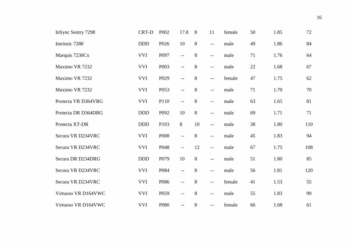
16
InSync Sentry 7298 CRT-D P002 17.8 8 11 female 50 1.85 72
Intrinsic 7288 DDD P026 10 8 -- male 49 1.86 84
Marquis 7230Cx VVI P097 -- 8 -- male 71 1.76 64
Maximo VR 7232 VVI P003 -- 8 -- male 22 1.68 67
Maximo VR 7232 VVI P029 -- 8 -- female 47 1.75 62
Maximo VR 7232 VVI P053 -- 8 -- male 71 1.70 70
Protecta VR D364VRG VVI P110 -- 8 -- male 63 1.65 81
Protecta DR D364DRG DDD P092 10 8 -- male 69 1.71 71
Protecta XT-DR DDD P103 8 10 -- male 38 1.80 110
Secura VR D234VRC VVI P008 -- 8 -- male 45 1.83 94
Secura VR D234VRC VVI P048 -- 12 -- male 67 1.75 108
Secura DR D234DRG DDD P079 10 8 -- male 51 1.80 85
Secura VR D234VRC VVI P084 -- 8 -- male 56 1.81 120
Secura VR D234VRC VVI P086 -- 8 -- female 41 1.53 55
Virtuoso VR D164VWC VVI P059 -- 8 -- male 55 1.83 99
Virtuoso VR D164VWC VVI P080 -- 8 -- female 66 1.68 61

17
Virtuoso VR D164VWC VVI P088 -- 8 -- male 70 1.76 77
Virtuoso VR D164VWC VVI P100 -- 8 -- female 52 1.68 73
St. Jude
Medical
Analyst Accel VR 1219-36 VVI P047 -- 11 -- male 59 1.79 95
Analyst Accel VR 1219-36 VVI P025 -- 11 -- male 49 1.80 94
Atlas + VR V-193 VVI P019 -- 11 -- male 63 1.75 84
Atlas + VR V-193 VVI P033 -- 11 -- male 59 1.76 81
Atlas + VR V-193 VVI P038 -- 11 -- male 56 1.82 90
Atlas + VR V-193 VVI P041 -- 11 -- male 56 1.80 96
Atlas + VR V-193 VVI P065 -- 11 -- female 47 1.70 85
Atlas + VR V-193 VVI P068 -- 11 -- male 53 1.72 95
Atlas + VR V-193 VVI P101 -- 11 -- male 68 1.70 85
Atlas + HF V-341 DDD P015 10 11 -- male 54 1.86 95
Atlas + HF V-341 CRT-D P073 10 11 male 68 1.81 83
Atlas DR V-242 VVI P090 -- 11 -- male 62 1.72 115
Atlas II + DR V-268 DDD P057 10 11 -- female 36 1.68 50

18
Atlas II VR V-168 VVI P001 -- 11 -- male 30 1.73 59
Atlas II VR V-168 VVI P010 -- 11 -- male 57 1.68 78
Atlas II VR V-168 VVI P012 -- 11 -- male 48 1.76 76
Atlas II VR V-168 VVI P024 -- 11 -- male 51 1.85 94
Atlas II VR V-168 VVI P032 -- 11 -- male 70 1.72 74
Atlas II VR V-168 VVI P034 -- 11 -- female 49 1.70 75
Atlas II VR V-168 VVI P035 -- 11 -- male 63 1.65 86
Atlas II VR V-168 VVI P040 -- 11 -- male 66 1.80 94
Atlas II VR V-168 VVI P052 -- 11 -- female 67 1.58 60
Atlas II VR V-168 VVI P075 -- 11 -- male 60 1.80 97
Atlas II VR V-168 VVI P081 -- 11 -- male 68 1.80 74
Atlas II VR V-168 VVI P102 -- 11 -- male 22 1.83 60
Current VR RF 1207-36 VVI P094 -- 11 -- male 71 1.68 87
Current + VR CD1211-36Q VVI P107 -- 11 -- male 49 1.84 90
Current + DR CD2211-36 DDD P089 10 11 -- male 30 1.96 104
Current Accel VR CD1215-36 VVI P087 -- 11 -- male 53 1.72 108

19
Fortify VR 1233-40Q VVI P106 -- 11 -- male 56 1.68 97
Promote Accel RF 3215-36 DDD P022 1.1 11 -- male 61 1.75 97
Promote Accel RF 3215-36 CRT-D P096 1.1 11 20 female 69 1.64 80
Promote RF 3213-16 CRT-D P027 10 11 20 male 60 1.86 71
Promote Q CRT-D P098 1.1 11 27 female 74 1.63 62
* Atrium
† Right ventricle
‡ Left ventricle

20
Supplemental Figures
Figure I. Comparison of minimum, mean and maximum value of the induced voltages
normalized to the body current for real field exposure and direct current injection of 6
volunteers.
Supplemental References
1. Joosten S, Pammler K, Silny J. The influence of anatomical and physiological parameters
on the interference voltage at the input of unipolar cardiac pacemakers in low frequency
electric fields. Physics in medicine and biology. 2009;54(3):591–609.