electromagnetic radial forces in a hybrid eight-stator
TRANSCRIPT

1
Abstract—Analysis and experimental measurement of the
electromagnet force loads on the hybrid rotor in a novel bearingless switched-reluctance motor (BSRM) have been performed. A BSRM has the combined characteristics of a switched-reluctance motor and a magnetic bearing. The BSRM has an eight-pole stator and a six-pole hybrid rotor, which is composed of circular and scalloped lamination segments. The hybrid rotor is levitated using only one set of stator poles. A second set of stator poles imparts torque to the scalloped portion of the rotor, which is driven in a traditional switched reluctance manner by a processor. Analysis was done for nonrotating rotor poles that were oriented to achieve maximum and minimum radial force loads on the rotor. The objective is to assess whether simple one-dimensional magnetic circuit analysis is sufficient for preliminary evaluation of this machine, which may exhibit strong three-dimensional electromagnetic field behavior. Two magnetic circuit geometries, approximating the complex topology of the magnetic fields in and around the hybrid rotor, were employed in formulating the electromagnetic radial force equations. Reasonable agreement between the experimental results and the theoretical predictions was obtained with typical magnetic bearing derating factors applied to the predictions.
Index Terms—Bearingless motor, electromagnetic device,
hybrid motor, magnetic field calculation, and switched-reluctance motor.*
I. NOMENCLATURE
0cA Common cross-sectional area between a stator
pole and circular lamination stack (m2)
aA Average of sbA and s
cA (m2) sbA Face area of stator pole 1 defined by length of
scalloped segment, 2×10⁻⁴ m2
scA Surface area inside scallop cavity, rθ Ls,
4.35×10⁻⁴ m2 ckA Common cross-sectional area between stator
pole k and circular lamination stack (m2) skA Common cross-sectional area between stator
pole k and scalloped lamination stack (m2)
Manuscript received February 23, 2007. Carlos R. Morrison is with the National Aeronautics and Space
Administration, Glenn Research Center, Cleveland, OH 44135 U.S.A. (phone: 216–433–8447; fax: 216–977–7051; e-mail: [email protected]).
Mark W. Siebert is with the University of Toledo, Cleveland, OH 44135 U.S.A. (e-mail: [email protected]).
Eric J. Ho was a summer intern at NASA Glenn Research Center and is now at University of Texas, Arlington, TX (email: [email protected]).*
0sA Common cross-sectional area between aligned
rotor and stator pole, 2×10⁻⁴ m2
B Flux density (T)
ckB Flux density between stator pole k and circular
rotor lamination stack (T) skB Flux density between stator pole k and scalloped
rotor lamination stack (T) ckE Energy density between stator pole k and circular
rotor laminations (J/m2) skE Energy density between stator pole k and
scalloped rotor laminations (J/m2) c
kF Magnetic force between circular lamination stack and stator pole k (N)
skF Magnetic force between scalloped lamination
stack and stator pole k (N)
Fm Magnetic force (N) c
netF Net downward magnetic force on circular rotor lamination stack (N)
snetF Net downward magnetic force on scalloped rotor
lamination stack (N)
( )c
T lowerF Magnetic force on circular rotor lamination due to stator poles 1, 2, and 8 (N)
( )s
T lowerF Magnetic force on scalloped rotor lamination due to stator poles 1, 2, and 8 (N)
FT(net_lev) Total net magnetic levitating force on the rotor (N)
( )_c
T net levF Total net magnetic levitation force on the circular rotor lamination due to stator poles 1, 2, 4, 5, 6, and 8 (N)
( )_s
T net levF Total net magnetic levitation force on the scalloped rotor lamination due to stator poles 1, 2, 4, 5, 6, and 8 (N)
Ft(net) Total net downward magnetic radial force on rotor (N)
_s
u netF Net downward magnetic radial force on the unaligned scallop segment (Fig. 10) (N)
Electromagnetic Radial Forces in a Hybrid Eight-Stator-Pole, Six-Rotor-Pole Bearingless
Switched-Reluctance Motor Carlos R. Morrison, Mark W. Siebert, and Eric J. Ho

2
Ft(u_net) Total net downward magnetic radial force on unaligned rotor (N)
( )c
T upperF Magnetic force on circular rotor lamination due to stator poles 5, 4, and 6 (N)
( )s
T upperF Magnetic force on scalloped rotor lamination due to stator poles 5, 4, and 6 (N)
g General gap width (m)
ga Average stator-rotor gap spacing at stator pole 1 or 5 (Fig. 10) (m)
gb Gap length between a corner edge of the salient stator pole 1 (Fig. 10) and either of its adjacent rotor salient pole corner edges (m)
gc Gap length between the midpoint of pole face 1 or 5 (Fig. 10) and the base of its adjacent scallop cavity (m)
gk Gap width at stator pole k (m)
g0 Nominal gap width, 5×10⁻⁴ (m)
i Current (A)
ik Current in coil k (A)
Lc Circular rotor lamination stack length, 5.88×10⁻³ m
Ls Scalloped rotor lamination stack length, 1.94×10⁻² m
ltw Tooth width, 1.03×10⁻² m
n Number of turns in coil, 215
Pk Permeance at stator pole k (H) c
kP Permeance between stator pole k and the circular rotor lamination stack (H)
skP Permeance between stator pole k and the
scalloped rotor lamination stack (H)
PT Sum of permeances (H) c
TP Sum of permeances at the circular laminations (H)
sTP Sum of permeances at the scalloped laminations
(H) ckR Reluctance between stator pole k and circular
lamination stack (1/H) skR Reluctance between stator pole k and scalloped
lamination stack (1/H) cTR Total reluctance at circular rotor lamination stack
(1/H) sTR Total reluctance at aligned rotor scalloped
lamination stack (1/H)
1sTR Total reluctance at scallop cavity through pole 1
(Fig. 10) (1/H)
0sR Nominal reluctance at the scalloped segment
(1/H)
5 _s
ratioR Reluctance ratio at pole 5 cR Parallel reluctance at circular rotor lamination
stack (1/H) sR Parallel reluctance at scalloped lamination stack
(1/H)
r Outer radius of rotor laminations (m)
v Flux volume between stator pole and rotor (m3) c
kV Flux volume between stator pole k and circular rotor laminations (m3)
skV Flux volume between stator pole k and scalloped
rotor laminations (m3) wm Magnetic energy (J)
ckw Magnetic energy between stator pole k and
circular rotor laminations (J) skw Magnetic energy between stator pole k and
scalloped rotor laminations (J) x Rotor vertical displacement from nominal
position (m) ckφ Magnetic flux between stator pole k and circular
laminations (Wb) skφ Magnetic flux between stator pole k and
scalloped laminations (Wb) φk Magnetic flux at stator pole k (Wb) μ0 Permeability of free space, 4π×10–7 H/m
II. INTRODUCTION There is a need for reliable, fail-safe, robust, compact, low-
cost electric motors for applications with high temperatures or extreme temperature variations; switched-reluctance motors possess these characteristics [1]. These motors have been evaluated as high-speed starter-generators [2] and [3]. However, conventional switched-reluctance motors can suffer from undesired vibration due to (1) unbalanced lateral forces on the rotor caused by electrical faults, (2) mechanical offset of the rotor, and (3) uncontrolled pulsed current in one or more shorted coils [4]. A viable solution for mitigating mechanical vibration is to suspend the rotor magnetically via self-levitation. In addition, magnetic suspension of the rotor allows the motor to operate at much higher rotational frequency for a prolonged period. This benefit is due largely to the elimination of friction, as there is no physical contact between the stator and rotor. Consequently, motors incorporating magnetic bearings perform at higher efficiency than motors incorporating ball bearings. Self-levitation also obviates the need for a lubrication system, which has the added benefit of significantly decreasing the weight and complexity of turbomachinery mechanisms.

3
Methods for simultaneously levitating and rotating a rotor within a single stator in switched-reluctance motors have been proposed in [5] and [6]. In these motors, the technique of using differential stator windings was employed. The studies in [5] and [6] center primarily around the use of a main four-pole winding to rotate an eight-pole rotor while utilizing a two-pole winding to apply radial force to the rotor with all of the 12 stator poles having both windings thereon. A variation on this theme was described in [7], wherein only a single coil on each stator pole (in a 12/8 stator-rotor pole configuration) was employed to achieve motor-bearing action.
Self-levitation (also called self-bearing) of motors has been achieved for nearly every type of electric motor, but is very marginal in performance for switched-reluctance motors with low numbers of poles. The motoring technique disclosed in [8] will simultaneously levitate and rotate a rotor, not only for (18/12) and (12/8) stator-rotor pole combinations, but also (8/6) and (6/4) configurations while employing a single set of coils positioned on each stator pole. The motoring techniques described in [5] to [7] are not applicable to motors having low stator-rotor pole configuration of (8/6) or (6/4) because of the dearth of stator-rotor poles in appropriate positions to apply levitating forces. The hybrid rotor technique described in [8] will assure robust bearingless operation in all four aforementioned stator-rotor pole configurations. With circular laminations on the shaft, levitating force is always assured as the rotor spins.
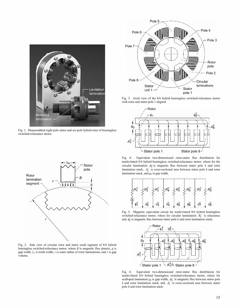
A disassembled eight-pole stator, six-pole hybrid rotor (motor) is shown in Fig. 1. The rotor lamination stack has a cylindrical portion of its length (indicated by the right arrow in the picture) used for levitation and a scalloped portion (indicated by the left arrow) used for both levitation and motoring. The currents in the coils of the eight-pole stator are controlled by an algorithm that handles both the levitating and motoring functions. During normal operation, two pairs of opposing stator poles (at right angles to each other) levitate the rotor. The remaining two pairs of stator poles exert torque on the six-pole rotor lamination stack to produce rotation. The relative lengths of the circular and multipole lamination stacks on the rotor can be chosen to tailor the performance of the motor for a specific application. For a given overall length, increasing the length of the multipole stack relative to the circular stack results in an increase in torque relative to levitation load capacity and stiffness, and vice versa. For this paper, the rotor has a 2.525×10⁻²-m- (1-in.-) long hybrid segment comprising a 5.883×10⁻³-m- (0.233-in.-) long section of circular laminations for levitation and a 1.937×10⁻²-m- (0.767-in.-) long portion having six salient poles for rotation.
This paper focuses exclusively on the nonrotating magnetic bearing action forces in the (8/6) hybrid motor. Two types of magnetic force measurements were made for the nonrotating rotor in which two diametrically opposed rotor poles were aligned with stator poles. In the first measurement, only one stator pole was energized, and the force on the centered rotor was recorded as a function of current. In this situation, the flux through the excited pole returns through a number of unexcited poles. In the second type of measurement, a
proportional-derivative (P-D) algorithm was used to levitate the nonrotating rotor. The rotor was then vertically displaced using a fixture containing a load cell, and the stator coil currents and force exerted on the rotor were recorded for each displacement value. In the corresponding analysis, the measured currents were utilized directly, thus making the calculations independent of the control law. The question this paper now seeks to answer is, can one successfully apply one-dimensional magnetic field analysis to the complex three-dimensional hybrid rotor to obtain the associated electromagnetic radial force?
A. Derivation of General Magnetic Force Equation Fig. 2 depicts a portion of the rotor and a portion of a stator
tooth on which the stator coil is energized to produce a magnetic field flux density B. The magnetic field interacts with the rotor at a distance g. The magnetic energy wm is thus given by the volume integral equation
2
0
12mw B dv= ∫∫∫μ
(1)
where μ0 is the permeability of free space. Integration over the gap volume is possible if the magnetic core material is operating within its linear range so that the energy stored in the core can be neglected compared with that in the gap.
Substituting ctwdv L l dg= in (1), and neglecting leakage
and fringing, yields
2
02c
m twBw L l dg= ∫μ
(2)
where Lc is the stack thickness of the circular laminations, ltw is the width of a stator tooth, and dg is the differential gap spacing. Taking the derivative of wm with respect to g produces the magnetic force relation
2
02cm
m twdw BF L ldg
= − = − ⋅μ
. (3)
The mathematical form and value of the B field impinging
on the asymmetric rotor will be determined next.
III. NONLEVITATED MAGNETIC EQUIVALENT CIRCUIT MODELING FOR CENTERED ROTOR
Fig. 3 is an axial view of the motor.
A. Circular Lamination Force Contribution A complex three-dimensional magnetic field topology
exists in and around the rotor because of its hybrid design. However, the analysis will be restricted to a one-dimensional approach in order to reduce the mathematical complexity of the static radial force derivation. Each rotor segment (circular lamination stack and scalloped lamination stack) will be treated as an independent entity, and accordingly, we develop a one-dimensional magnetic radial force description for each
4
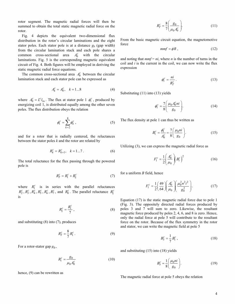
rotor segment. The magnetic radial forces will then be summed to obtain the total static magnetic radial force on the rotor.
Fig. 4 depicts the equivalent two-dimensional flux distribution in the rotor’s circular laminations and the eight stator poles. Each stator pole is at a distance g0 (gap width) from the circular lamination stack and each pole shares a common cross-sectional area 0
cA with the circular laminations. Fig. 5 is the corresponding magnetic equivalent circuit of Fig. 4. Both figures will be employed in deriving the static magnetic radial force equations.
The common cross-sectional area 0cA between the circular
lamination stack and each stator pole can be expressed as 0 , 1...8c c
kA A k= = (4) where 0
c ctwA L l= . The flux at stator pole 1 1
cφ , produced by energizing coil 1, is distributed equally among the other seven poles. The flux distribution obeys the relation
8
12
c ck
k== ∑φ φ , (5)
and for a rotor that is radially centered, the reluctances between the stator poles k and the rotor are related by 1, 1...7c c
k kR R k+= = . (6) The total reluctance for the flux passing through the powered pole is 1
c c cTR R R= + (7)
where 1
cR is in series with the parallel reluctances 2cR , 3
cR , 4cR , 5
cR , 6cR , 7
cR , and 8cR . The parallel reluctance cR
is
17
cc R
R = , (8)
and substituting (8) into (7), produces
187
c cTR R= . (9)
For a rotor-stator gap 0g ,
01
0 0
cc
gR
A=μ
(10)
hence, (9) can be rewritten as
0
0 0
87
cT c
gR
A
⎛ ⎞= ⎜ ⎟⎜ ⎟
⎝ ⎠μ. (11)
From the basic magnetic circuit equation, the magnetomotive force mmf R= φ , (12)
and noting that mmf = ni, where n is the number of turns in the coil and i is the current in the coil, we can now write the flux expression
1c
cT
niR
=φ . (13)
Substituting (11) into (13) yields
0 01
0
78
cc A ni
g⎛ ⎞
= ⎜ ⎟⎜ ⎟⎝ ⎠
μφ . (14)
The flux density at pole 1 can thus be written as
011
00
78
cc
cni
BgA
⎛ ⎞= = ⎜ ⎟
⎝ ⎠
μφ. (15)
Utilizing (3), we can express the magnetic radial force as
( )201 1
0
12
cc cA
F B⎛ ⎞
= ⎜ ⎟⎜ ⎟⎝ ⎠μ
(16)
for a uniform B field, hence
2 2 2
0 01 2
0 0
1 492 64
cc A n i
Fg
⎛ ⎞⎛ ⎞⎛ ⎞= ⎜ ⎟⎜ ⎟⎜ ⎟⎜ ⎟⎜ ⎟⎝ ⎠⎝ ⎠⎝ ⎠
μμ
. (17)
Equation (17) is the static magnetic radial force due to pole 1 (Fig. 3). The oppositely directed radial forces produced by poles 3 and 7 will sum to zero. Likewise, the resultant magnetic force produced by poles 2, 4, 6, and 8 is zero. Hence, only the radial force at pole 5 will contribute to the resultant force on the rotor. Because of the flux symmetry in the rotor and stator, we can write the magnetic field at pole 5
5 117
c cB B= , (18)
and substituting (15) into (18) yields
05
0
18
c niB
g⎛ ⎞
= ⎜ ⎟⎝ ⎠
μ. (19)
The magnetic radial force at pole 5 obeys the relation
5
( )205 5
0
12
cc cA
F B⎛ ⎞
= ⎜ ⎟⎜ ⎟⎝ ⎠μ
(20)
hence
2 2 2
0 05 2
0 0
1 12 64
cc A n i
Fg
⎛ ⎞⎛ ⎞⎛ ⎞= ⎜ ⎟⎜ ⎟⎜ ⎟⎜ ⎟⎜ ⎟⎝ ⎠⎝ ⎠⎝ ⎠
μμ
. (21)
The net downward magnetic force produced by poles 1 and 5 on the circular laminations is given as
1 5
c c cnetF F F= − . (22)
Substituting (17) and (21) into (22) yields the net downward magnetic force on the circular lamination stack,
2
20 02
0
38
cc
netA n
F ig
⎛ ⎞= ⎜ ⎟⎜ ⎟
⎝ ⎠
μ. (23)
Substituting the actual value of the constants gives 25.037c
netF i= . (24)
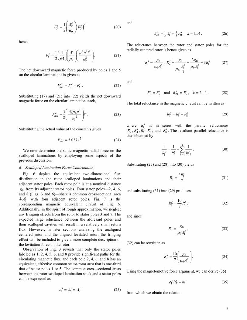
We now determine the static magnetic radial force on the scalloped laminations by employing some aspects of the previous discussion.
B. Scalloped Lamination Force Contribution Fig. 6 depicts the equivalent two-dimensional flux
distribution in the rotor scalloped laminations and their adjacent stator poles. Each rotor pole is at a nominal distance
0g from its adjacent stator poles. Four stator poles—2, 4, 6, and 8 (Figs. 3 and 6)—share a common cross-sectional area 1
03sA with four adjacent rotor poles. Fig. 7 is the
corresponding magnetic equivalent circuit of Fig. 6. Additionally, in the spirit of rough approximation, we neglect any fringing effects from the rotor to stator poles 3 and 7. The expected large reluctance between the aforesaid poles and their scalloped cavities will result in a relatively small return flux. However, in later sections analyzing the unaligned centered rotor and the aligned levitated rotor, the fringing effect will be included to give a more complete description of the levitation force on the rotor.
Observation of Fig. 3 reveals that only the stator poles labeled as 1, 2, 4, 5, 6, and 8 provide significant paths for the circulating magnetic flux, and each pole 2, 4, 6, and 8 has an equivalent, effective common stator-rotor area that is one-third that of stator poles 1 or 5. The common cross-sectional areas between the rotor scalloped lamination stack and a stator poles can be expressed as
1 5 0
s s sA A A= = (25)
and 1 1
2 1 03 3 , 1...4s s skA A A k= = = . (26)
The reluctance between the rotor and stator poles for the radially centered rotor is hence given as
0 0 01 2 1
0 1 1 0 10
3, 3
3
s s ss s s
g g gR R R
A A A= = = =μ μμ
(27)
and 1 5 2 2 and , 2...4s s s s
kR R R R k= = = . (28)
The total reluctance in the magnetic circuit can be written as
1s s sTR R R= + (29)
where 1
sR is in series with the parallel reluctances 2sR , 4
sR , 5sR , 6
sR , and 8sR . The resultant parallel reluctance is
thus obtained by
4
5 21
1 1 1s s s
kkR R R=
= +∑ . (30)
Substituting (27) and (28) into (30) yields
137
ss R
R = (31)
and substituting (31) into (29) produces
1107
s sTR R= , (32)
and since
01
0 1
ss
gR
A=μ
, (33)
(32) can be rewritten as
0
0 1
107
sT s
gR
A
⎛ ⎞= ⎜ ⎟⎜ ⎟
⎝ ⎠μ. (34)
Using the magnetomotive force argument, we can derive (35) 1
s sTR ni=φ (35)
from which we obtain the relation

6
1s
sT
niR
=φ . (36)
Substituting (34) into (36) yields
0 11
0
710
ss A ni
g⎛ ⎞
= ⎜ ⎟⎜ ⎟⎝ ⎠
μφ . (37)
The flux density extant at pole 1 and its adjacent salient rotor pole is thus given by
011
01
710
ss
sni
BgA
⎛ ⎞= = ⎜ ⎟
⎝ ⎠
μφ. (38)
The magnetic force is represented as
( )211 1
0
12
ss sA
F B⎛ ⎞
= ⎜ ⎟⎜ ⎟⎝ ⎠μ
, (39)
and substituting (38) into (39) engenders the expression
2 2 201
1 20 0
1 492 100
ss n iA
Fg
⎛ ⎞⎛ ⎞⎛ ⎞= ⎜ ⎟⎜ ⎟⎜ ⎟⎜ ⎟⎜ ⎟⎝ ⎠⎝ ⎠⎝ ⎠
μμ
. (40)
Equation (40) represents the magnetic force, due to stator pole 1, on the aligned salient pole of the rotor. The resultant magnetic force on the rotor, produced by poles 2 and 8, cancels the resultant magnetic force produced by poles 4 and 6. Hence, only the magnetic force at pole 5 will contribute to the resultant force on the rotor. The flux at pole 5 can be expressed as
4
5 1 21
s s sk
k== −∑φ φ φ . (41)
The flux relation can be written as
2 2 , 2...4s s
k k= =φ φ , (42)
and substituting (42) into (41) results in the simplified expression
5 1 24s s s= −φ φ φ . (43)
Flux symmetry consideration allows us to write the relation
2 117
s s=φ φ , (44)
and substituting (44) into (43) yields
0 55
0
310
ss A ni
g⎛ ⎞
= ⎜ ⎟⎜ ⎟⎝ ⎠
μφ . (45)
The flux density at pole 5 is thus given as
5 05
05
310
ss
sni
BgA
⎛ ⎞= = ⎜ ⎟
⎝ ⎠
φ μ, (46)
and the magnetic force between pole 5 and its adjacent salient rotor pole is given by
( )255 5
0
12
ss sA
F B⎛ ⎞
= ⎜ ⎟⎜ ⎟⎝ ⎠μ
. (47)
Substituting (46) into (47) yields
2 2 2
5 05 2
0 0
1 92 100
ss A n i
Fg
⎛ ⎞⎛ ⎞⎛ ⎞= ⎜ ⎟⎜ ⎟⎜ ⎟⎜ ⎟⎜ ⎟⎝ ⎠⎝ ⎠⎝ ⎠
μμ
. (48)
The net downward magnetic force produced by poles 1 and 5 on their corresponding salient rotor poles is thus given by
1 5
s s snetF F F= − . (49)
Substituting (40) and (48) into (49) yield the force expression
2
20 020
15
ss
netA n
F ig
⎛ ⎞= ⎜ ⎟⎜ ⎟
⎝ ⎠
μ (50)
where 0
s stwA L l= . Equation (50) represents the net downward
magnetic force on the scalloped lamination stack. Substituting the actual values of the constants gives
28.845s
netF i= . (51)
The total net downward magnetic force on the centered nonlevitated hybrid rotor is the sum of the net downward magnetic force on the circular lamination stack and the net downward magnetic force on the scalloped lamination stack: ( )
c st net net netF F F= + . (52)
Substituting (24) and (51) into (52) yields
2
( ) 13.88t netF i= . (53)
The fraction of force contributed by the circular lamination segment is

7
2
2( )
5.037 0.36 36%13.88
cnet
t net
F iF i
= = , (54)
and the fraction by the scalloped segment is
2
2( )
8.845 0.64 64%13.88
snet
t net
F iF i
= = . (55)
Note that the circular lamination stack experiences approximately 36% of the total net downward magnetic force, while the scalloped lamination experience approximately 64% of said force. The stack lengths of the circular and scalloped laminations are Lc = 0.23 and Ls = 0.77, respectively. Note that the forces in (54) and (55) are not proportional to the stack lengths. This discrepancy is due to the differences in return paths of the flux in the hybrid rotor. The following section outlines the experimental procedure for obtaining the nonlevitated magnetic radial force on the rotor.
C. Experimental Centered-Force Procedure The experimental nonlevitated magnetic radial force on the
rotor was obtained by mounting the rotor between two load cells (see Fig. 8) while ensuring that the rotor’s axis was radially centered in the stator. A salient rotor pole was aligned with stator pole 1 (see Fig. 3). The preload voltages of the cells were then zeroed to eliminate the preload weight from the data. Stator pole 1 was energized, and the resulting magnetic force on the rotor produced a larger reading on the lower cell and a smaller reading on the upper cell. The difference in the readings gave the net force on the rotor. This procedure was repeated for several values of coil current ranging from 0.982 to 2.027 A. The procedure was repeated with pole 5 as the sole energized pole.
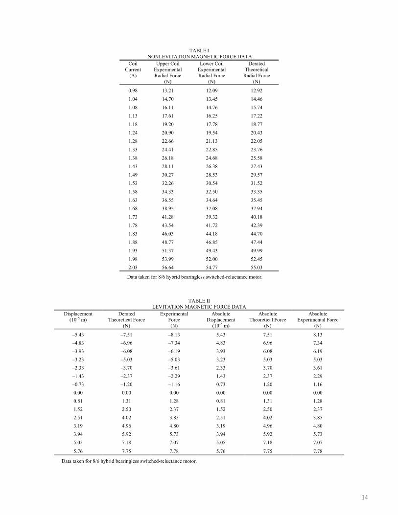
D. Experimental and Theoretical Centered-Force Comparison
The experimental and theoretical magnetic force data are presented in Table I, and the related magnetic force plots are shown in Fig. 9. Because of flux leakage and field fringing effects at the stator and rotor pole edges, uncertainties in geometry, rotor-stator alignment, and material properties, we must apply a derating factor to (53). Reference [9] presents a detailed treatment of the derating factor, wherein a factor of 0.88 was determined for one particular active magnetic bearing. In contrast, a graph in [10] shows a derating factor of 0.6 for our gap g0 (5×10⁻⁴ m). This rotor’s configuration is, of course, different from that of a pure magnetic bearing. A derating of 0.87 gives the closest agreement with the experimental results obtained for the hybrid rotor (see (56) and Fig. 9): ( ) 2
( ) 13.88 0.87t netF i= × . (56)
Fig. 9 depicts the experimental least-squares-fit magnetic
force curves for the upper and lower poles, and the theoretical magnetic force curve. In the following section, the
nonlevitated unaligned rotor-stator radial force equations are derived for the hybrid rotor.
E. Nonlevitated Unaligned Rotor Analysis The analysis presented in previous sections clearly
demonstrates that one can make a reasonably accurate prediction of electromagnet forces on a radially centered hybrid rotor using two-dimensional visualization and one-dimensional electromagnetic force analysis. With this fact established, we will estimate the radial force on the unaligned radially centered rotor, that is, a rotor that is rotated so that the motoring section has an unfavorable misalignment with the powered stator pole 1, as depicted in Fig. 10. Using a force symmetry argument similar to that presented in earlier sections, it can be shown that only poles 1 and 5 are relevant in determining the net force on the hybrid rotor. The analysis begins by approximating the reluctance between poles 1 or 5 and the adjacent scallop cavities:
1 50
s sa
a
gR R
A= =μ
(57)
where 2
b ca
g gg
+⎛ ⎞= ⎜ ⎟⎝ ⎠
is the average stator-rotor gap spacing
at stator poles 1 or 5 (Fig. 10), gb is the distance between a corner edge of the salient stator pole 1 or 5 and either of its adjacent salient rotor pole corner edges, and gc is the gap length between the midpoint of either pole face and the base of
its adjacent scallop cavity. Here, 2
s sb c
aA A
A⎛ ⎞+
= ⎜ ⎟⎜ ⎟⎝ ⎠
is the
average of the stator pole face area sbA and its adjacent scallop
cavity area scA . The face area of pole 1 is 4 2
0 2 10 ms sbA A −= = × and the surface area inside a scallop
cavity was determined to be 4 24.35 10 mscA −= × .
Substituting these values into the average stator-rotor gap spacing and area expressions result in ga = 6.25×10⁻³ m and Aa = 3.17×10⁻⁴ m2. We can rewrite Aa in terms of 0
sA :
00
1.59, 1.59 saas
AA A
A= = × , (58)
and ag in terms of 0g :
00
12.5, 12.5aa
gg g
g= = × . (59)
Substituting these values into (57) yields
01 0
0 0 07.86 7.86s sa
sa
g gR R
A A= = =μ μ
(60)

8
where 0sR is the nominal reluctance at the scalloped segment.
Substituting the actual value of the constant yields 7 1
1 5 07.86 1.57 10 Hs s sR R R −= = = × . (61)
Here, the estimated reluctance at the unaligned pole is almost eight times that of an aligned pole. Note that this value of the reluctance applies to both poles 1 and 5. The remaining pole reluctances are
0 0 0 02 4 6 8
0 2 0 4 0 6 0 8
0 03 7
0 3 0 7
, , , ,
, and .
s s s ss s s s
s ss s
g g g gR R R R
A A A Ag g
R RA A
μ μ μ μ
μ μ
= = = =
= = (62)
We know that
3 7 0
s s sA A A= = (63) hence 3 7 0
s s sR R R= = (64) then
0 02 0
0 000
33
3
s sss
g gR R
AA μμ
= = =⎛ ⎞⎜ ⎟⎜ ⎟⎝ ⎠
(65)
where 2 2 , 2...4s s
kR R k= = . The total parallel reluctance due to poles 2, 3, 4, 5, 6, 7, and 8 is given as
2 3 5
1 4 2 1s s s sR R R R= + + , (66)
and substituting (61), (64), and (65) into (66) gives
0 0 0
1 4 2 13 7.86s s s sR R R R
= + + . (67)
Equation (67) simplifies to 00.29s sR R= , (68) hence, the total reluctance of the magnetic circuit through pole 1 is 1 1 0 0 07.86 0.29 8.15s s s s s s
TR R R R R R= + = + = . (69)
Substituting 6 100
0 01.99 10 Hs
sg
RA
−= = ×μ
into (69) gives
7 11 1.63 10 Hs
TR −= × . The total flux at pole 1 has the form
( )81
16.15 10 Hs
sT
ni niR
−= = ×φ (70)
from which we can determine the flux density:
( )8
2 211 4 2
0
6.15 10 H 6.63 10 H/m2 10 m
ss
sB ni iA
−−
−
⎛ ⎞×= = = ×⎜ ⎟⎜ ⎟×⎝ ⎠
φ. (71)
The radial force at pole 1 is thus
( )2 201 1
0
1 0.352
ss sA
F B i⎛ ⎞
= =⎜ ⎟⎜ ⎟⎝ ⎠μ
. (72)
The next task is to determine the flux fraction at pole 5,
which will allow computation of the magnetic force at pole 5. The difference between this force and the force at pole 1 will give the net magnetic force on the unaligned hybrid rotor.
The fraction of the total flux passing through pole 5 is determined by its reluctance ratio, the combined parallel reluctance of all the return poles divided by the reluctance of pole 5:
05 _
5 0
0.290.037
7.86
s ss
ratio s s
R RR
R R= = . (73)
The flux at pole 5 is now obtained by employing (70):
5 5 _ 11
0.037s s sratio s
T
niRR
φ φ= = × (74)
or simply 7
5 4.86 10s i−= ×φ . (75) The force at pole 5 is
( )25 4 2
50 0
4.71 102
ss
sF iA
−= = ×φ
μ. (76)
The net downward magnetic radial force on the unaligned scalloped section of the rotor due to poles 1 and 5 is _ 1 5
s s su netF F F= − . (77)
Substituting (72) and (76) into (77) produces

9
( )4 2_ 0.35 4.71 10s
u netF i−= − × (78)
or more simply
2_ 0.35s
u netF i . (79) The ratio of the net downward magnetic force on the unaligned scalloped stack to that on the aligned scalloped stack s
netF is
2
_2
0.35 0.039 3.9%8.85
su net
snet
F iF i
= = . (80)
Note that the unaligned scallop magnetic force load is only 3.9% of the magnetic force load produced by the aligned scallop. This is a reasonable result, considering the large reluctances of the scallop cavities located at poles 1 and 5. Taking into account the contributions of the circular laminations, the total net downward magnetic radial force on the unaligned rotor is ( _ ) _
c st u net net u netF F F= + . (81)
We know from (24) and (51) that the aligned net radial
force on the circular laminations and scallops are 25.037c
netF i and 28.845snetF i , respectively, from which
the total net downward magnetic force on the aligned rotor is ( )
c st net net netF F F= + . (82)
The ratio of the total net downwards magnetic force of the unaligned rotor to the total net downwards magnetic force on the aligned rotor is
2
( _ )2
( )
(5.037 0.348) 0.39 39%(5.037 8.845)
t u net
t net
F iF i
+= =
+. (83)
Equations (80) and (83) highlight the importance of the circular lamination stack; that is, the load capacity in the unaligned orientation is substantially enhanced by the circular lamination segment. In subsequent sections, the general levitation force equations are derived for the hybrid rotor that is displaced vertically from its radially centered position within the stator.
IV. LEVITATION MAGNETIC EQUIVALENT CIRCUIT MODELING The analysis begins by employing the magnetic equivalent
circuit depicted in Fig. 11, which relates to the magnetically levitated state of the nonrotating, aligned, vertically displaced hybrid rotor. The rotor was magnetically levitated using stator poles 1, 3, 5, and 7 (Fig. 3).
A. Levitation Flux Derivation We designate the coil currents as i1, i3, i5, and i7 for the
respective stator poles 1, 3, 5, and 7. Each coil has n turns. These currents generate the magnetic fluxes 1φ , 3φ , 5φ , 7φ ,
2,8φ , and 4,6φ , where 2,8φ and 4,6φ represent the return fluxes due to pole pairs (2 and 8) and (4 and 6) on either side of pole 1 and pole 5, respectively. Referencing Fig. 11, (84) to (88) are written by applying the magnetic circuit equation to various closed paths (all of which go through pole 1, which has a permeance 1P ):
3 13 1
3 1ni ni
P P− = +
φ φ (84)
5 15 1
5 1ni ni
P P+ = +
φ φ (85)
7 17 1
7 1ni ni
P P− = +
φ φ (86)
2,8 11
2,8 10 ni
P P+ = +
φ φ (87)
4,6 11
4,6 10 ni
P P+ = +
φ φ . (88)
Conservation of the magnetic flux assures that the sum of the magnetic fluxes is equal to zero, hence
1 3 5 7 2,8 4,6 0+ + + + + =φ φ φ φ φ φ . (89) The solution of (84) to (89) is given by
11 3 3 5 5 7 7
3 5 7 2,8 4,6 1( )T
PP i P i P i
P
P P P P P i n
φ ⎡= − − +⎣
⎤+ + + + + ⎦
(90)
3
3 1 1 5 5 7 7
1 5 7 2,8 4,6 3( )T
PP i P i P i
P
P P P P P i n
φ ⎡= + −⎣
⎤+ + + + + ⎦
(91)
5
5 3 3 1 1 7 7
1 3 7 2,8 4,6 5( )T
PP i P i P i
P
P P P P P i n
φ ⎡= − − +⎣
⎤+ + + + + ⎦
(92)
7
7 1 1 3 3 5 5
1 3 5 2,8 4,6 7( )T
PP i P i P i
P
P P P P P i n
φ ⎡= − +⎣
⎤+ + + + + ⎦
(93)

10
[ ]2,82,8 1 1 3 3 5 5 7 7
T
PPi P i P i P i n
P= − + −φ (94)
[ ]4,64,6 1 1 3 3 5 5 7 7
T
PPi P i P i P i n
P= − + −φ (95)
where for notational convenience we define the sum of permeances as
1 3 5 7 2,8 4,6TP P P P P P P≡ + + + + + . (96)
Equations (90), (92), (94), (95), and (96) are used to derive
the electromagnetic levitation force equations for the rotor displaced vertically inside the stator. In subsequent sections, separate magnetic force equations for the circular and scalloped lamination segments are derived.
B. Levitation Force on the Circular Laminations The common cross-sectional area between the circular
laminations and pole 1 or 5 is given as 0c c
twA L l= . The rotor’s vertical displacement x from its nominal position affects the gap widths gk, hence 1 0g g x= + (97) at stator pole 1, and 5 0g g x= − (98) at stator pole 5. In addition, the gaps at the return flux poles 2 and 8 can be written as 2,8 0 cos(45 )g g x= + ° (99) and for poles 4 and 6 4,6 0 cos(45 )g g x= − ° (100)
where 45° is the angle between adjacent poles. The approximate permeances between the poles and the circular lamination stack are
0 03 7 0
0
cc c c A
P P Pg
= = =μ
(101)
0 0 0 0 0 01 5 2,8
1 5 2,8
0 04,6
4,6
2, , ,
2and ,
c c cc c c
cc
A A AP P P
g g g
AP
g
μ μ μ
μ
= = =
=
(102)
and applying (96) to the circular laminations,
1 3 5 7 2,8 4,6c c c c c c c
TP P P P P P P≡ + + + + + . (103)
The flux at pole 5 is obtained by utilizing (92):
( )
55 3 3 1 1 7 7
1 3 7 2,8 4,6 5 .
cc c c c
cT
c c c c c
PP i P i P i
P
P P P P P i n
⎡= − − +⎣
⎤+ + + + + ⎦
φ (104)
The equations for the magnetic field, energy density, flux volume, and energy at pole 5 are,
55
0
( )( )
cc
cx
B xA
=φ
(105a)
2
55
0
[ ( )]( )
2
cc B x
E x =μ
(105b)
5 0 5( ) ( )c cV x A g x= (105c) 5 5 5( ) ( ) ( )c c cw x V x E x= (105d) respectively. The magnetic force on the rotor due to pole 5 is then obtained by differentiating the magnetic energy 5
cw with respect to the rotor displacement, hence
5 55 5
( ) ( )( )
c cc cdw x dV x
F E xdx dx
= − = − . (106)
Using (95), the return magnetic flux equation for poles 4 and 6 is
( )4,64,6 1 1 3 3 5 5 7 7
cc c c c c
cT
PP i P i P i P i n
P= − + −φ (107)
where c
TP is the sum of permeances at the circular laminations. The equations for the magnetic field, energy density, flux volume, and energy at poles 4 and 6 are,
4,64,6
0
( )( )
cc
c
xB x
A=φ
(108a)
24,6
4,60
( )( )
2
cc
B xE x
⎡ ⎤⎣ ⎦=
μ (108b)
4,6 0 4,6( ) 2 ( )c cV x A g x= (108c) 4,6 4,6 4,6( ) ( ) ( )c c cw x V x E x= (108d)
11
respectively. The magnetic force due to poles 4 and 6 is
4,6 4,64,6 4,6
( ) ( )( )
c cc cdw x dV x
F E xdx dx
= − = − . (109)
The total magnetic force due to pole 5 and its adjacent poles 4 and 6 is thus
( ) 5 4,6
c c cT upperF F F= + . (110)
Similarly, we can calculate the net downward magnetic force created by poles 1, 2, and 8. The magnetic force at pole 1 is
1 11 1
( ) ( )( )
c cc cdw x dV x
F E xdx dx
= − = − , (111)
and the magnetic force due to the return flux poles 2 and 8 is thus given as
2,8 2,82,8 2,8
( ) ( )( )
c cc cdw x dV x
F E x sdx dx
= − = − . (112)
The total magnetic force due to pole 1 and its adjacent poles 2 and 8 is thus ( ) 1 2,8
c c cT lowerF F F= + . (113)
The net magnetic levitation force on the circular laminations, due to poles 1, 2, 4, 5, 6, and 8 can now be written: ( _ ) ( ) ( )
c c cT net lev T upper T lowerF F F= + . (114)
Note that for the vertically displaced rotor, the net force on the circular lamination stack, due to poles 3 and 7, is identically zero.
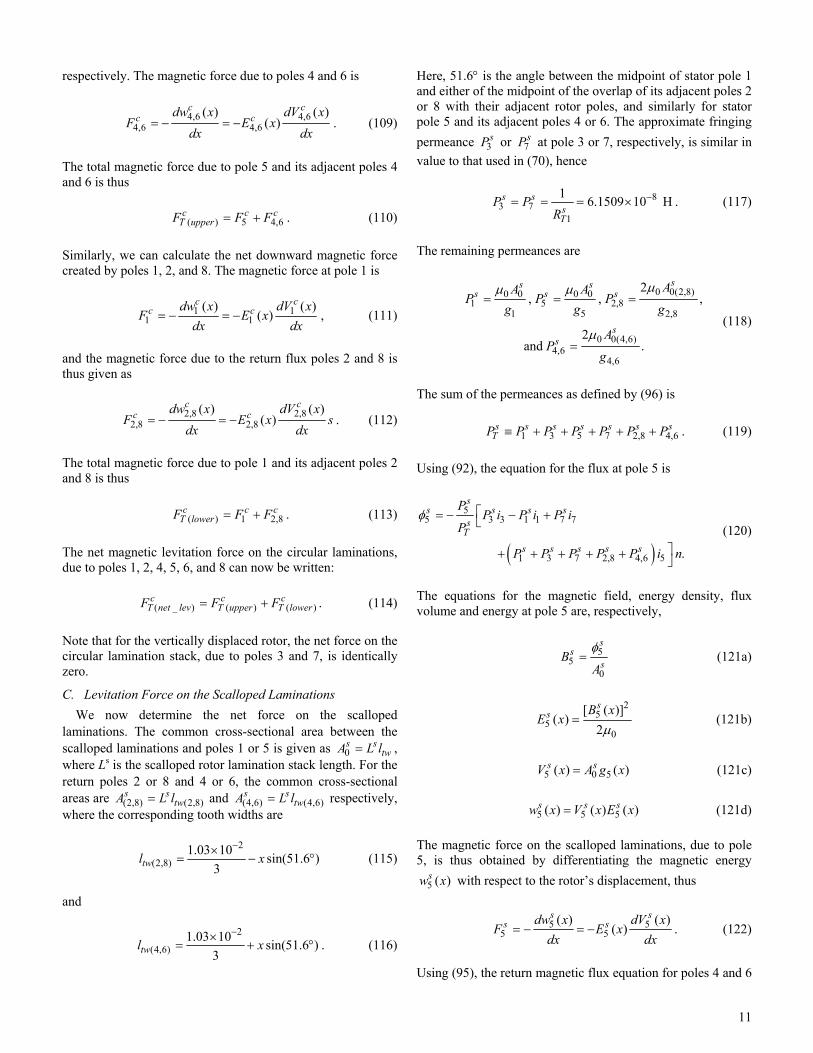
C. Levitation Force on the Scalloped Laminations We now determine the net force on the scalloped
laminations. The common cross-sectional area between the scalloped laminations and poles 1 or 5 is given as 0
s stwA L l= ,
where Ls is the scalloped rotor lamination stack length. For the return poles 2 or 8 and 4 or 6, the common cross-sectional areas are (2,8) (2,8)
s stwA L l= and (4,6) (4,6)
s stwA L l= respectively,
where the corresponding tooth widths are
2
(2,8)1.03 10 sin(51.6 )
3twl x−×
= − ° (115)
and
2
(4,6)1.03 10 sin(51.6 )
3twl x−×
= + ° . (116)
Here, 51.6° is the angle between the midpoint of stator pole 1 and either of the midpoint of the overlap of its adjacent poles 2 or 8 with their adjacent rotor poles, and similarly for stator pole 5 and its adjacent poles 4 or 6. The approximate fringing permeance 3
sP or 7sP at pole 3 or 7, respectively, is similar in
value to that used in (70), hence
83 7
1
1 6.1509 10 Hs ssT
P PR
−= = = × . (117)
The remaining permeances are
0 0(2,8)0 0 0 01 5 2,8
1 5 2,8
0 0(4,6)4,6
4,6
2, , ,
2and .
ss ss s s
ss
AA AP P P
g g g
AP
g
= = =
=
μμ μ
μ (118)
The sum of the permeances as defined by (96) is 1 3 5 7 2,8 4,6
s s s s s s sTP P P P P P P≡ + + + + + . (119)
Using (92), the equation for the flux at pole 5 is
( )
55 3 3 1 1 7 7
1 3 7 2,8 4,6 5 .
ss s s s
sT
s s s s s
PP i P i P i
P
P P P P P i n
⎡= − − +⎣
⎤+ + + + + ⎦
φ (120)
The equations for the magnetic field, energy density, flux volume and energy at pole 5 are, respectively,
55
0
ss
sB
A=φ
(121a)
2
55
0
[ ( )]( )
2
ss B x
E x =μ
(121b)
5 0 5( ) ( )s sV x A g x= (121c) 5 5 5( ) ( ) ( )s s sw x V x E x= (121d) The magnetic force on the scalloped laminations, due to pole 5, is thus obtained by differentiating the magnetic energy
5 ( )sw x with respect to the rotor’s displacement, thus
5 55 5
( ) ( )( )
s ss sdw x dV x
F E xdx dx
= − = − . (122)
Using (95), the return magnetic flux equation for poles 4 and 6
12
is
( )4,64,6 1 1 3 3 5 5 7 7
ss s s s s
sT
PP i P i P i P i n
P= − + −φ . (123)
The equations for the magnetic field, energy density, flux volume, and energy at poles 4 and 6 are, respectively,
4,64,6
4,6=
ss
sBA
φ (124a)
2
4,64,6
0
[ ( )]( )
2
ss B x
E x =μ
(124b)
4,6 4,6 4,6( ) 2 ( )=s sV x A g x (124c) 4,6 4,6 4,6( ) ( ) ( )s s sw x V x E x= (124d) and the equation for the magnetic force due to poles 4 and 6 is now given as
4,6 4,64,6 4,6
( ) ( )( )
s ss sdw x dV x
F E xdx dx
= − = − (125)
where 4,6 0 cos(51.6 )g g x= − ° and 51.6° is the angle between the midpoint of stator pole 5 and either of the midpoint of the overlap of its adjacent poles 4 or 6 with their adjacent rotor pole. The equation for the total magnetic force due to pole 5 and its adjacent poles 4 and 6 on the scalloped laminations is thus ( ) 5 4,6
s s sT upperF F F= + . (126)
Similarly, we can calculate the net magnetic force created by poles 1, 2, and 8. The magnetic force at pole 1 is
1 11 1
( ) ( )( )
s ss sdw x dV x
F E xdx dx
= − = − , (127)
and the magnetic force due to the return flux poles 2 and 8 is thus given as
2,8 2,82,8 2,8
( ) ( )( )
s ss sdw x dV x
F E xdx dx
= − = − . (128)
The total magnetic force due to pole 1 and its adjacent poles 2 and 8 is hence ( ) 1 2,8
s s sT lowerF F F= + . (129)
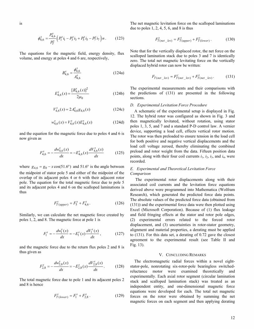
The net magnetic levitation force on the scalloped laminations due to poles 1, 2, 4, 5, 6, and 8 is thus
( _ ) ( ) ( )
s s sT net lev T upper T lowerF F F= + . (130)
Note that for the vertically displaced rotor, the net force on the scalloped lamination stack due to poles 3 and 7 is identically zero. The total net magnetic levitating force on the vertically displaced hybrid rotor can now be written: ( _ ) ( _ ) ( _ )
c sT net lev T net lev T net levF F F= + . (131)
The experimental measurements and their comparisons with the predictions of (131) are presented in the following sections.
D. Experimental Levitation Force Procedure A schematic of the experimental setup is displayed in Fig.
12. The hybrid rotor was configured as shown in Fig. 3 and then magnetically levitated, without rotation, using stator poles 1, 3, 5, and 7 and a standard P-D control law. A vernier device, supporting a load cell, effects vertical rotor motion. The rotor was then preloaded to ensure tension in the load cell for both positive and negative vertical displacements and the load cell voltage zeroed, thereby eliminating the combined preload and rotor weight from the data. Fifteen position data points, along with their four coil currents i1, i2, i3, and i4, were recorded.
E. Experimental and Theoretical Levitation Force Comparison
The experimental rotor displacements along with their associated coil currents and the levitation force equations derived above were programmed into Mathematica (Wolfram Research), which generated the predicted force data points. The absolute values of the predicted force data (obtained from (131)) and the experimental force data were then plotted using Excel (Microsoft Corporation). Because of (1) flux leakage and field fringing effects at the stator and rotor pole edges, (2) experimental errors related to the forced rotor displacement, and (3) uncertainties in rotor-stator geometry, alignment and material properties, a derating must be applied to (131). For this data set, a derating of 0.72 gave the closest agreement to the experimental result (see Table II and Fig. 13).
V. CONCLUDING REMARKS The electromagnetic radial forces within a novel eight-
stator-pole, nonrotating six-rotor-pole bearingless switched-reluctance motor were examined theoretically and experimentally. Each axial rotor segment (circular lamination stack and scalloped lamination stack) was treated as an independent entity, and one-dimensional magnetic force equations were developed for each. The total net magnetic forces on the rotor were obtained by summing the net magnetic forces on each segment and then applying derating
13
factors of 0.87 for the nonlevitated case and 0.72 for the levitated case. In addition, it was demonstrated analytically that the load capacity of the rotor in the unaligned orientation is substantially enhanced by the presence of a circular lamination segment (this is critical for maintaining rotor stability during the motoring operation). Based on the analysis, we conclude that two-dimensional visualization and one-dimensional magnetic field analysis can be used for estimating electromagnetic levitation forces on the hybrid rotor with a derating factor of about 0.8 applied to the calculated force.
ACKNOWLEDGMENT The novel rotor (motor) was developed with support from
the NASA “Strategic Research Fund” (SRF) Combined Motor/Magnetic Bearing Project (Dr. Marvin Goldstein, manager), the “Revolutionary Aeropropulsion Concept” (RAC) Project, High Power Density Motors for Aircraft Propulsion (Mr. Leo Burkardt, manager) and subsequent support from the “Alternate Fuel Foundation Technology” (AFFT), with Mr. Dave Ercegovic as project manager.
Special recognition is extended to Dr. Gerald V. Brown for his many insightful discussions that ultimately led to the theoretical analysis presented in this paper, Mr. Ben Ebihara and Mr. Carl Buccieri for their contributions in fabricating the motor, and Mr. Joseph Wisniewski and Mr. Gerald Buchar for their assistance with the motor’s electrical and electronics wiring.
REFERENCES [1] G. Montague, et al., “High-temperature switched-reluctance electric
motor,” NASA Tech Briefs, Feb. 2003. [2] E. Richter and C. Ferreira, “Performance evaluation of a 250 kW
switched reluctance starter generator,” IEEE IAS’95, 1995, pp. 434−440.
[3] S.R. MacMinn and W.D. Jones, “A very high speed switched-reluctance starter-generator for aircraft engine applications,” Aerospace and Electronics Conference, IEEE’ 89, 1989, pp. 1758−1764.
[4] T.J.E. Miller, “Faults and unbalance forces in the switched reluctance machine,” IEEE Trans. Ind. Applicat., vol. 31, pp. 319−328, Mar./Apr. 1995.
[5] M. Takemoto, K. Shimada, A. Chiba, and T. Fukao, “A design and characteristics of switched reluctance type bearingless motors,” in Proc. 4th Int. Symp. Magnetic Suspension Technology, NASA/CP⎯1998-207654, May 1998, pp. 49−63.
[6] M. Takemoto, H. Suzuki, A. Chiba, T. Fukao, and M.A. Rahman, “Improved analysis of a bearingless switched reluctance motor,” IEEE Trans. Ind. Applicat., vol. 37, Jan./Feb. 2001.
[7] M.A. Preston, J.P.F. Lyons, E. Richter, and K. Chung, “Integrated magnetic bearing/switched reluctance machine,” U.S. Patent 5,424,595, June 13, 1995.
[8] C.R. Morrison, “Bearingless switched reluctance motor,” U.S. Patent 6,727,618 B1, Apr. 27, 2004.
[9] J.T. Marshall, M.E.F. Kasarda, and J. Imlach, “A multipoint measurement technique for the enhancement of force measurement with active magnetic bearings,” ASME Trans., vol. 125, pp. 90−94, Jan. 2003.
[10] C.R. Knospe and E.H. Maslen, “Introduction to active magnetic bearing,” presented at NASA Lewis Research Center, Cleveland, OH, Feb. 24−25, 1999.
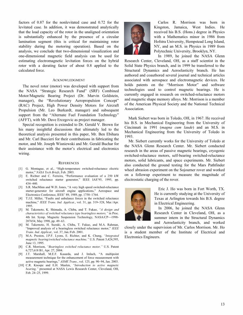
Carlos R. Morrison was born in Kingston, Jamaica, West Indies. He received his B.S. (Hons.) degree in Physics with a Mathematics minor in 1986 from Hofstra University, Hempstead Long Island, NY, and an M.S. in Physics in 1989 from Polytechnic University, Brooklyn, NY.
In 1989, he joined the NASA Glenn Research Center, Cleveland, OH, as a staff scientist in the Solid State Physics branch, and in 1999 he transferred to the Structural Dynamics and Aeroelasticity branch. He has authored and coauthored several journal and technical articles associated with aerospace and electromagnetic devices. He holds patents on the “Morrison Motor” and software technologies used to control magnetic bearings. He is currently engaged in research on switched-reluctance motors and magnetic shape memory alloys. Mr. Morrison is a member of the American Physical Society and the National Technical Association.
Mark Siebert was born in Toledo, OH, in 1967. He received his B.S. in Mechanical Engineering from the University of Cincinnati in 1991 (magna cum laude) and an M.S. in Mechanical Engineering from the University of Toledo in 1993.
Mr. Siebert currently works for the University of Toledo at the NASA Glenn Research Center. Mr. Siebert conducted research in the areas of passive magnetic bearings, cryogenic switched-reluctance motors, self-bearing switched-reluctance motors, solid lubricants, and space experiments. Mr. Siebert also conducted the ground testing for the Mars Pathfinder wheel abrasion experiment on the Sojourner rover and worked on a followup experiment to measure the magnitude of electrostatic charging of the rover.
Eric J. Ho was born in Fort Worth, TX. He is currently studying at the University of Texas at Arlington towards his B.S. degree in Electrical Engineering.
In 2006, he joined the NASA Glenn Research Center in Cleveland, OH, as a summer intern in the Structural Dynamics and Aeroelasticity branch, and worked
closely under the supervision of Mr. Carlos Morrison. Mr. Ho is a student member of the Institute of Electrical and Electronics Engineers.
14
TABLE I
NONLEVITATION MAGNETIC FORCE DATA Coil
Current (A)
Upper Coil Experimental Radial Force
(N)
Lower Coil Experimental Radial Force
(N)
Derated Theoretical
Radial Force (N)
0.98 13.21 12.09 12.92 1.04 14.70 13.45 14.46 1.08 16.11 14.76 15.74 1.13 17.61 16.25 17.22 1.18 19.20 17.78 18.77 1.24 20.90 19.54 20.43 1.28 22.66 21.13 22.05 1.33 24.41 22.85 23.76 1.38 26.18 24.68 25.58 1.43 28.11 26.38 27.43 1.49 30.27 28.53 29.57 1.53 32.26 30.54 31.52 1.58 34.33 32.50 33.35 1.63 36.55 34.64 35.45 1.68 38.95 37.08 37.94 1.73 41.28 39.32 40.18 1.78 43.54 41.72 42.39 1.83 46.03 44.18 44.70 1.88 48.77 46.85 47.44 1.93 51.37 49.43 49.99 1.98 53.99 52.00 52.45 2.03 56.64 54.77 55.03
Data taken for 8/6 hybrid bearingless switched-reluctance motor.
TABLE II LEVITATION MAGNETIC FORCE DATA
Displacement (10–5 m)
Derated Theoretical Force
(N)
Experimental Force (N)
Absolute Displacement
(10–5 m)
Absolute Theoretical Force
(N)
Absolute Experimental Force
(N)
–5.43 –7.51 –8.13 5.43 7.51 8.13 –4.83 –6.96 –7.34 4.83 6.96 7.34 –3.93 –6.08 –6.19 3.93 6.08 6.19 –3.23 –5.03 –5.03 3.23 5.03 5.03 –2.33 –3.70 –3.61 2.33 3.70 3.61 –1.43 –2.37 –2.29 1.43 2.37 2.29 –0.73 –1.20 –1.16 0.73 1.20 1.16 0.00 0.00 0.00 0.00 0.00 0.00 0.81 1.31 1.28 0.81 1.31 1.28 1.52 2.50 2.37 1.52 2.50 2.37 2.51 4.02 3.85 2.51 4.02 3.85 3.19 4.96 4.80 3.19 4.96 4.80 3.94 5.92 5.73 3.94 5.92 5.73 5.05 7.18 7.07 5.05 7.18 7.07
5.76 7.75 7.78 5.76 7.75 7.78
Data taken for 8/6 hybrid bearingless switched-reluctance motor.
15
Fig. 1. Disassembled eight-pole stator and six-pole hybrid rotor of bearingless switched-reluctance motor.
Fig. 2. Side view of circular rotor and stator tooth segment of 8/6 hybrid bearingless switched-reluctance motor, where B is magnetic flux density, g is gap width, ltw is tooth width, r is outer radius of rotor laminations, and v is gap volume.
Fig. 3. Axial view of the 8/6 hybrid bearingless switched-reluctance motor with rotor and stator pole 1 aligned.
Fig. 4. Equivalent two-dimensional rotor-stator flux distribution for nonlevitated 8/6 hybrid bearingless switched-reluctance motor, where for the circular lamimation c
kφ is magnetic flux between stator pole k and rotor lamination stack, c
kA is cross-sectional area between stator pole k and rotor lamination stack, and g0 is gap width.
Fig. 5. Magnetic equivalent circuit for nonlevitated 8/6 hybrid bearingless switched-reluctance motor, where for circular lamimation c
kR is reluctance and c
kφ is magnetic flux between stator pole k and rotor lamination stack.
Fig. 6. Equivalent two-dimensional rotor-stator flux distribution for nonlevitated 8/6 hybrid bearingless switched-reluctance motor, where for scalloped lamination g0 is gap width, s
kφ is magnetic flux between stator pole k and rotor lamination stack, and s
kA is cross-sectional area between stator pole k and rotor lamination stack.

16
Fig. 7. Magnetic equivalent circuit for nonlevitated 8/6 hybrid bearingless switched-reluctance motor, where for scalloped lamination s
kR is reluctance and s
kφ is magnetic flux between stator pole k and rotor lamination stack.
Fig. 8. Experimental setup used in obtaining nonlevitation magnetic radial forces for 8/6 hybrid bearingless switched reluctance motor (BSRM).
Fig. 9. Nonlevitation magnetic radial force curves for 8/6 hybrid bearingless switched-reluctance motor. Experimental least-squares-fit curves (dotted lines) for upper and lower poles and theoretical curve (solid line).
Fig. 10. Axial view of 8/6 hybrid bearingless switched-reluctance motor with rotor and stator pole 1 unaligned.
Fig. 11. Magnetic equivalent circuit for levitated 8/6 hybrid bearingless switched-reluctance motor, where ik is current in coil k, Pk is permeance at stator pole k, and φk is magnetic flux at stator pole k.
Fig. 12. Experimental setup used in obtaining levitation magnetic radial forces for 8/6 hybrid bearingless switched reluctance motor (BSRM).
Fig. 13. Experimental (dotted line) and theoretical (solid line) levitation magnetic radial force curves for 8/6 hybrid bearingless switched-reluctance motor.