electromagnetic shielding : earthing and coupling
TRANSCRIPT

1
T.C
SÜLEMAN DEMİREL UNIVERSITY
FEN BİLİMLERİ ENSTİTÜSÜ
Mühendislik fakültesi
ELEKTRONİK VE HABERLEŞME MÜHENDİSLİĞİ
COURSE SUBJECT
ELECTROMAGNETIC SHIELDING
COURSE OFFERED By
Prof. Dr. Mustafa MERDAN
ELECTROMAGNETIC SHIELDING
“EARTHING AND COUPLING”
Submitted by MSc. Student
Badri -Khalid Saeed Lateef Al
Student No. 1330145002

2
ELECTROMAGNETIC SHIELDING
“EARTHING AND COUPLING “
Submitted by MSc. Student
Khalid S. Al-Badri

3
Background and basic definitions .................................................................................... 6
Electromagnetic radiation ................................................................................................................... 6
History of the theory ........................................................................................................................... 7
Electromagnetic field .......................................................................................................................... 8
Mathematical description .................................................................................................................... 9
Electromagnetic radiation ................................................................................................................... 9
Electromagnetic spectrum ................................................................................................................. 12
A Review of Electromagnetic Material Properties ........................................................................... 14
Conductors ........................................................................................................................................ 14
Dielectrics ......................................................................................................................................... 15
Magnetic materials ............................................................................................................................ 16
EMI and EMC ................................................................................................................................... 17
Basic Definitions:.............................................................................................................................. 17
Origin Of EMI : ................................................................................................................................ 18
EMS( Electromagnetic Susceptibility) .............................................................................................. 19
EMC (Electromagnetic Compatibility) ............................................................................................. 19
Classification of EMI: ....................................................................................................................... 20
Intra-system Interference .................................................................................................................. 20
Inter-system Interference .................................................................................................................. 21
Types of EMI: ................................................................................................................................... 21
Radiated Emission: ........................................................................................................................... 22
Conducted Emission: ........................................................................................................................ 22
Radiated Susceptibility (Immunity): ................................................................................................. 22
Conducted Susceptibility (Immunity): .............................................................................................. 22
Popular Instances of EMI/EMC: ....................................................................................................... 22
Chapter 2 ....................................................................................................................................... 23
Noise .................................................................................................................................................. 23
Introduction ....................................................................................................................................... 23
Intrinsic Noise ................................................................................................................................... 23
Extrinsic Noise .................................................................................................................................. 23
Environmental perturbations ......................................................................................................... 24
Crosstalk noise .............................................................................................................................. 24
Physical Noise Sources ..................................................................................................................... 24
Thermal Noise ............................................................................................................................... 24

4
Diffusion Noise ............................................................................................................................. 25
Quantum Noise ............................................................................................................................. 25
External Noise Sources ..................................................................................................................... 26
Natural Noise Sources ....................................................................................................................... 26
Atmospheric Noise ........................................................................................................................ 26
Precipitation Static ........................................................................................................................ 27
Galactic Noise ............................................................................................................................... 27
Man-Made Noise Sources ................................................................................................................. 28
Electromagnetic Noise Sources .................................................................................................... 28
Electrostatic Noise Sources ........................................................................................................... 31
Noise Parameters .............................................................................................................................. 32
Normalized Power ........................................................................................................................ 32
Noise Bandwidth ........................................................................................................................... 33
Equivalent noise resistance ........................................................................................................... 33
Noise Ratio .................................................................................................................................... 33
Signal-to-Noise Ratio .................................................................................................................... 33
Chapter 3 ....................................................................................................................................... 35
Earthed and Grounded .......................................................................................................... 35
Introduction: ...................................................................................................................................... 35
Earthed .............................................................................................................................................. 37
History .............................................................................................................................................. 38
WHY GROUND? ............................................................................................................................. 39
Personnel Safety: .............................................................................................................................. 39
Equipment and Building Protection: ................................................................................................. 40
Electrical Noise Reduction: .............................................................................................................. 40
Types of grounding ........................................................................................................................... 42
Building exterior grounds ............................................................................................................. 42
System grounding or earthing ....................................................................................................... 47
Grounding Structure Characteristics ................................................................................................. 49
GROUND RESISTANCE ................................................................................................................ 50
Conductivity of Different Soil Types................................................................................................ 51
Electric Shock ................................................................................................................................... 53
Lightning - an overview .................................................................................................................... 62
Lightning protection .......................................................................................................................... 64

5
Active attraction systems .................................................................................................................. 66
Passive neutral systems ..................................................................................................................... 66
Active prevention systems ................................................................................................................ 66
A new approach to lightning protection ............................................................................................ 69
Noise in signaling circuits ................................................................................................................. 72
Solutions ........................................................................................................................................... 75
High frequency grounding configuration .......................................................................................... 77
Chapter 4 ....................................................................................................................................... 79
ELECTROMAGNETIC Coupling ........................................................................................... 79
Introduction: ...................................................................................................................................... 79
Methods of Noise Coupling .................................................................................................................. 80
Coupling Paths .................................................................................................................................. 80
Conducted Noise ............................................................................................................................... 81
AC Power Lines ............................................................................................................................ 81
Common Ground Impedance ........................................................................................................ 81
Maxwell‘s Equation and Electromagnetic Coupling Principle ..................................................... 82
Review of Directional Couplers .................................................................................................... 84
Two-Line Coupled ............................................................................................................................ 86
Backward-Wave Directional Couplers ............................................................................................. 87
Comparison of Tight Directional Couplers ....................................................................................... 88
Braided Shields (Example1) ............................................................................................................. 90
Spiral Shields (Example2) ................................................................................................................ 92
Ribbon Cables Shields (Example3) .................................................................................................. 92
References ............................................................................................................................................. 95

6
Chapter 1
Background and basic definitions
Electromagnetic radiation
Electromagnetism is the study of the electromagnetic force which is a
type of physical interaction that occurs between electrically charged particles.
The electromagnetic force usually manifests as electromagnetic fields, such as
electric fields, magnetic fields and light. The electromagnetic force is one of the
four fundamental interactions in nature. The other three are the strong
interaction, the weak interaction, and gravitation.[8]
The electromagnetic force
plays a major role in
determining the internal
properties of most objects
encountered in daily life.
Ordinary matter takes its
form as a result of
intermolecular forces
between individual
molecules in matter. Electrons are bound by electromagnetic wave mechanics
into orbitals around atomic nuclei to form atoms, which are the building blocks
of molecules. This governs the processes involved in chemistry, which arise
from interactions between the electrons of neighboring atoms, which are in turn
determined by the interaction between electromagnetic force and the momentum
of the electrons.
There are numerous mathematical descriptions of the electromagnetic field. In
classical electrodynamics, electric fields are described as electric potential and

7
electric current in Ohm's law, magnetic fields are associated with
electromagnetic induction and magnetism, and Maxwell's equations describe
how electric and magnetic fields are generated and altered by each other and by
charges and currents.[9]
The theoretical implications of electromagnetism, in particular the establishment
of the speed of light based on properties of the "medium" of propagation
(permeability and permittivity), led to the development of special relativity by
Albert Einstein in 1905.
Although electromagnetism is considered one of the four fundamental forces, at
high energy the weak force and electromagnetism are unified. In the history of
the universe, during the quark epoch, the electroweak force split into the
electromagnetic and weak forces.
History of the theory
Originally electricity and magnetism were
thought of as two separate forces. This view
changed, however, with the publication of
James Clerk Maxwell's 1873 A Treatise on
Electricity and Magnetism in which the
interactions of positive and negative charges
were shown to be regulated by one force. There
are four main effects resulting from these
interactions, all of which have been clearly demonstrated by experiments:
1. Electric charges attract or repel one another with a force inversely
proportional to the square of the distance between them: unlike charges
attract, like ones repel.

8
2. Magnetic poles (or states of polarization at individual points) attract or
repel one another in a similar way and always come in pairs: every north
pole is yoked to a south pole.
3. An electric current in a wire creates a circular magnetic field around the
wire, its direction (clockwise or counter-clockwise) depending on that of
the current.
4. A current is induced in a loop of wire when it is moved towards or away
from a magnetic field, or a magnet is moved towards or away from it, the
direction of current depending on that of the movement.
Electromagnetic field
An electromagnetic field (also
EMF or EM field) is a physical
field produced by electrically
charged objects. It affects the
behavior of charged objects in the
vicinity of the field. The electromagnetic field extends indefinitely throughout
space and describes the electromagnetic interaction. It is one of the four
fundamental forces of nature (the others are gravitation, weak interaction and
strong interaction).
The field can be viewed as the combination of an electric field and a magnetic
field. The electric field is produced by stationary charges, and the magnetic field
by moving charges (currents); these two are often described as the sources of
the field. The way in which charges and currents interact with the
electromagnetic field is described by Maxwell's equations and the Lorentz force
law.

9
From a classical perspective in the history of electromagnetism, the
electromagnetic field can be regarded as a smooth, continuous field, propagated
in a wavelike manner; whereas from the perspective of quantum field theory,
the field is seen as quantized, being composed of individual particles.
Mathematical description
The behaviour of electric and magnetic fields, whether in cases of electrostatics,
magnetostatics, or electrodynamics (electromagnetic fields), is governed by
Maxwell's equations. In the vector field formalism, these are:
where ρ is the charge density, which can (and often does) depend on time and
position, ε is the permittivity of free space, μ is the permeability of free space,
and J is the current density vector, also a function of time and position. The
units used above are the standard SI units. Inside a linear material, Maxwell's
equations change by switching the permeability and permittivity of free space
with the permeability and permittivity of the linear material in question. Inside
other materials which possess more complex responses to electromagnetic
fields, these terms are often represented by complex numbers, or tensors.[10]
Electromagnetic radiation
Electromagnetic radiation (EM radiation or EMR) is a form of radiant energy
released by certain electromagnetic processes. Visible light is one type of
electromagnetic radiation, other familiar forms are invisible electromagnetic
radiations such as X-rays and radio waves.

10
Classically, EMR consists of electromagnetic waves, which are synchronized
oscillations of electric and magnetic fields that propagate at the speed of light.
The oscillations of the two fields are perpendicular to each other and
perpendicular to the direction of energy and wave propagation, forming a
transverse wave. Electromagnetic waves can be characterized by either the
frequency or wavelength of their oscillations to form the electromagnetic
spectrum, which includes, in order of increasing frequency and decreasing
wavelength: radio waves, microwaves, infrared radiation, visible light,
ultraviolet radiation, X-rays and gamma rays.
Electromagnetic waves are produced whenever charged particles are
accelerated, and these waves can subsequently interact with any charged
particles. EM waves carry energy, momentum and angular momentum away
from their source particle and can impart those quantities to matter with which
they interact. EM waves are massless, but they are still affected by gravity.
Electromagnetic radiation is associated with those EM waves that are free to
propagate themselves ("radiate") without the continuing influence of the moving
charges that produced them, because they have achieved sufficient distance
from those charges. Thus, EMR is sometimes referred to as the far field. In this
jargon, the near field refers to EM fields near the charges and current that
directly produced them, as (for example) with simple magnets, electromagnetic
induction and static electricity phenomena.

11
In the quantum theory of electromagnetism, EMR consists of photons, the
elementary particles responsible for all electromagnetic interactions. Quantum
effects provide additional sources of EMR, such as the transition of electrons to
lower energy levels in an atom and black-body radiation. The energy of an
individual photon is quantized and is greater for photons of higher frequency.
This relationship is given by Planck's equation
E=hν,
where E is the energy per photon, ν is the frequency of the photon, and h is
Planck's constant. A single gamma ray photon, for example, might carry
~100,000 times the energy of a single photon of visible light.
The effects of EMR upon biological systems (and also to many other chemical
systems, under standard conditions) depend both upon the radiation's power and
its frequency. For EMR of visible frequencies or lower (i.e., radio, microwave,

12
infrared), the damage done to cells and other materials is determined mainly by
power and caused primarily by heating effects from the combined energy
transfer of many photons. By contrast, for ultraviolet and higher frequencies
(i.e., X-rays and gamma rays), chemical materials and living cells can be further
damaged beyond that done by simple heating, since individual photons of such
high frequency have enough energy to cause direct molecular damage.
Electromagnetic spectrum
The electromagnetic spectrum is the range of all possible frequencies of
electromagnetic radiation. The "electromagnetic spectrum" of an object has a
different meaning, and is instead the characteristic distribution of
electromagnetic radiation emitted or absorbed by that particular object.
The electromagnetic spectrum extends from below the low frequencies used for
modern radio communication to gamma radiation at the short-wavelength (high-
frequency) end, thereby covering wavelengths from thousands of kilometers
down to a fraction of the size of an atom. The limit for long wavelengths is the
size of the universe itself, while it is thought that the short wavelength limit is in
the vicinity of the Planck length.[11] Until the middle of last century it was
believed by most physicists that this spectrum was infinite and continuous.
Most parts of the electromagnetic spectrum are used in science for spectroscopic
and other probing interactions, as ways to study and characterize matter.[6] In
addition, radiation from various parts of the spectrum has found many other
uses for communications and manufacturing (see electromagnetic radiation for
more applications).

13

14
A Review of Electromagnetic Material Properties
Different types of matter have a variety of useful electrical and magnetic
properties. Some are conductors, and some are insulators. Some, like iron and
nickel, can be magnetized, while others have useful electrical properties, e.g.,
dielectrics, which allow us to make capacitors with much higher values of
capacitance than would otherwise be possible. We need to organize our
knowledge about the properties that materials can possess, and see whether this
knowledge allows us to calculate anything useful with Maxwell's equations.
Conductors
A perfect conductor, such as a superconductor, has no DC electrical resistance.
It is not possible to have a static electric field inside it, because then charges
would move in response to that field, and the motion of the charges would tend
to reduce the field, contrary to the assumption that the field was static. Things
are a little different at the surface of a perfect conductor than on the interior. We
expect that any net charges that exist on the conductor will spread out under the
influence of their mutual repulsion, and settle on the surface. Gauss's law
requires that the fields on the two sides of a sheet of charge have |E ⊥,1 −E ⊥,2 |
proportional to the surface charge density, and since the field inside the
conductor is zero, we infer that there can be a field on or immediately outside
the conductor, with a nonvanishing component perpendicular to the surface. The
component of the field parallel to the surface must vanish, however, since
otherwise it would cause the charges to move along the surface.
In a perfect conductor, there is no ohmic heating. Since electric fields can't
penetrate a perfect conductor, we also know that an electromagnetic wave can
never pass into one. By conservation of energy, we know that the wave can't
just vanish, and if the energy can't be dissipated as heat, then the only remaining

15
possibility is that all of the wave's energy is reflected. This is why metals, which
are good electrical conductors, are also highly reflective. They are not perfect
electrical conductors, however, so they are not perfectly reflective. The wave
enters the conductor, but immediately excites oscillating currents, and these
oscillating currents dissipate the energy both by ohmic heating and by
reradiating the reflected wave. Since the parts of Maxwell's equations
describing radiation have time derivatives in them, the efficiency of this
reradiation process depends strongly on frequency. When the frequency is high
and the material is a good conductor, reflection predominates, and is so efficient
that the wave only penetrates to a very small depth, called the skin depth. In the
limit of poor conduction and low frequencies, absorption predominates, and the
skin depth becomes much greater. In a high-frequency AC circuit, the skin
depth in a copper wire is very small, and therefore the signals in such a circuit
are propagated entirely at the surfaces of the wires. In the limit of low
frequencies, i.e., DC, the skin depth approaches infinity, so currents are carried
uniformly over the wires' cross-sections.
We can quantify how well a particular material conducts electricity. We know
that the resistance of a wire is proportional to its length, and inversely
proportional to its cross-sectional area. The constant of proportionality is 1/σ ,
where σ is called the electrical conductivity. Exposed to an electric field E , a
conductor responds with a current per unit cross-sectional area J=σE . The skin
depth is proportional to 1/√ (fσ) , where f is the frequency of the wave.
Dielectrics
A material with a very low conductivity is an insulator. The atoms motion
cannot create an electric current. But even though they have zero charge, they
may not have zero dipole moment. Let take the example capacitor, the effect has
been to cancel out part of the charge that was deposited on the plates of the

16
capacitor. Now this is very subtle,
because Maxwell's equations treat
these charges on an equal basis,
but in terms of practical
measurements, they are
completely different. Although
the relationship E↔q between
electric fields and their sources is unalterably locked in by Gauss's law, that's
not what we see in practical measurements. The conventional notation is to
incorporate this fudge factor into Gauss's law by defining an altered version of
the electric field,
D=ϵE,
and to rewrite Gauss's law as Φ D =q in, free .
The constant ϵ is a property of the material, known as its permittivity. In a
vacuum, ϵ takes on a value known as ϵ o , defined as 1/(4πk) . In a dielectric, ϵ
is greater than ϵo.
Magnetic materials
Atoms and molecules may have magnetic
dipole moments as well as electric dipole
moments. Just as an electric dipole
contains bound charges, a magnetic dipole
has bound currents, which come from the
motion of the electrons. The magnetic
field,
H=B/μ

17
The constant μ is the permeability, with a vacuum value of μ o =4πk/c2 .
EMI and EMC
Widespread use of electric and electronic systems for household,
industrial, communication and other application makes it necessary for circuits
to operate in close proximity of each other. Often these circuits affect
performance of other near or far region electromagnetic fields. This interference
is thus called ELECTROMAGNETIC INTERFERENCE (EMI), and is
emerging to be a major problem for circuit designers. In addition the use of
integrated circuits are being put in less space close to each other, thereby
increasing the problem of interference.
Equipment designers need to make sure that their equipment will work in the
real world with other equipments nearby. This implies that the performance of
the equipment should neither be affected by external noise sources nor should
itself be a source of noise. Avoidance of EMI is a major design objective,
besides the principal objective of achieving intended circuit function.
ELECTROMAGNETIC COMPATIBILITY (EMC) is the ability of any
electronic equipment to be able to operate properly despite if the interference
from its intended electromagnetic environment and equally important not to be
a source of undue interference to other equipment intended to work in the same
environment.
Basic Definitions:
Electromagnetic interference (EMI) is an unwanted disturbance that affects
an electrical circuit due to electromagnetic radiation emitted from an external
source. The disturbance may interrupt, obstruct, or otherwise degrade or limit
the effective performance of the circuit. The source may be any object, artificial
or natural, that carries rapidly changing electrical currents, such as an electrical
circuit, the Sun or the Northern lights.

18
EMI can be induced intentionally for radio jamming, as in some forms of
electronic warfare, or unintentionally, as a result of spurious emissions and
responses, intermodulation products, and the like. It frequently affects the
reception of AM radio in urban areas. It can also affect cell phone, FM radio
and television reception, although to a lesser extent.
Electromagnetic compatibility (EMC) is the branch of electrical sciences
which studies the unintentional generation, propagation and reception of
electromagnetic energy with reference to the unwanted effects (Electromagnetic
Interference, or EMI) that such energy may induce. The goal of EMC is the
correct operation, in the same electromagnetic environment, of different
equipment which uses electromagnetic phenomena, and the avoidance of any
interference effects. In order to achieve this, EMC pursues two different kinds
of issues. Emission issues are related to the unwanted generation of
electromagnetic energy by some source, and to the countermeasures which
should be taken in order to reduce such generation and to avoid the escape of
any remaining energies into the external environment. Susceptibility or
immunity issues, in contrast, refer to the correct operation of electrical
equipment, referred to as the victim, in the presence of unplanned
electromagnetic disturbances. Interference, or noise, mitigation and hence
electromagnetic compatibility is achieved primarily by addressing both
emission and susceptibility issues, i.e., quieting the sources of interference and
hardening the potential victims. The coupling path between source and victim
may also be separately addressed to increase its attenuation.
Origin Of EMI :
The origins of EMI are basically -
• Radiated emissions (electric and/or magnetic fields)

19
• Undesired conducted emissions (voltages and/or currents).
EMS( Electromagnetic Susceptibility)
It is the ability of an electronic device/equipment/system to function
satisfactorily in an electromagnetic environment.
EMC (Electromagnetic Compatibility)
EMC=EMI + EMS
• It is the ability of an electronic device, equipment, system to function
satisfactorily in its electromagnetic environment.
• At the same time it doesn‘t introduce intolerable electromagnetic
disturbance to any other device /equipment / system in that environment.
A system is Electro-Magnetically Compatible (EMC) if:
• It does not cause interference with other systems.
• It is not susceptible to emission from other systems.
• It does not cause interference with itself.

20
Classification of EMI:
EMI broad types:
• Intra system
• •Inter system
Intra-system Interference
If the cause of EMI problem is within the system it is termed as Intra-system
interference.
Intra-System EMI Causes:

21
Inter-system Interference
If the cause of the EMI problem is from the outside of the system it is termed as
Intersystem Interference.
Intersystem EMI Causes:
Types of EMI:
• Radiated Emission (RE)
• Conducted Emission (CE)
• Radiated Immunity/Susceptibility (RS)
• Conducted Immunity/Susceptibility (CS)
• Electrostatic Discharge (ESD)
• Electric Fast Transient (EFT)
• Surges (Lightning)

22
Radiated Emission:
Radiated emission is the energy propagated through free space in the form of
electromagnetic waves.
Conducted Emission:
Conducted emission is the energy propagated through a conducting media in the
form of electromagnetic waves.
Radiated Susceptibility (Immunity):
Undesired potential EMI that is radiated into an equipment or system from
hostile outside electromagnetic sources.
Conducted Susceptibility (Immunity):
Undesired potential EMI that is conducted into an equipment or system from
hostile outside sources.
Popular Instances of EMI/EMC:
Radiated Emission: From Nearby Radio Transmitters
ESD (Electro-static discharge): Transfer of static charge between the
application and something else.
EFT: Electrical Fast Transient Power Disturbance to equipment.
Surge: Lightning Indirect Strike of Lightning (Power Surge).
EMP: Electromagnetic Pulse
Intense electromagnetic wave caused by a nuclear detonation.

23
Chapter 2
Noise
Introduction
In signal processing, noise is a general term for unwanted (and, in general,
unknown) modifications that a signal may suffer during capture, storage,
transmission, processing, or conversion.[12]
Sometimes the word is also used to mean signals that are random
(unpredictable) and carry no useful information; even if they are not interfering
with other signals or may have been introduced intentionally, as in comfort
noise.
The IEEE Standard Dictionary defines noise as unwanted disturbances
superposed upon a useful signal that tend to obscure its information content.
This definition is versatile, since it applies both to intrinsic and extrinsic noise
(intrinsic noise is the noise generated inside a system, while the term extrinsic
noise designates noise originating elsewhere).[13]
Intrinsic Noise
This term refers to the noise generated inside an investigated device or circuit.
In linear systems the physical origin of noise is the discrete nature of charge
carriers. Consequently, the number of carriers in some specific plane fluctuates
in time. These fluctuations are both universal and unavoidable.
A typical example is thermal noise, originating from the random motion of free
electrons inside a piece of conductive material.
Extrinsic Noise
The sources of extrinsic noise are situated outside the investigated circuit, which
merely acts as a receiving antenna; for this reason this kind of noise is also

24
called extraneous signals, or spurious signals, or perturbations. According to its
possible origins, two main categories exist:
Environmental perturbations
such as sky noise (which includes strong broadband noise sources like the Sun
and the Milky Way), atmospheric noise (caused mainly by lightning discharges
in thunderstorms), manmade noise (due to electric motors, arc welding, power
lines, neon signs, electrostatic discharge, electrical power equipment, radio and
TV broadcast services, motors, switches, spark plugs in ignition systems,
household appliances, cellular telephones, mobile radios, etc.). All industrial
perturbations are characterized by relatively high amplitudes, and a spectrum
that cuts off before reaching visible wavelengths. Many are regular in form and
periodic.
Crosstalk noise
Signals which are useful in one circuit, but unfortunately pass via parasitic
coupling into nearby circuits, where they are undesired and therefore act as
perturbations. As a general rule, the user discovers the interference (i.e., the
undesirable effect of spurious signals) during operation and not before!
Sometimes, such coupling can be reduced by modifying the relative position of
various cables or equipment in a rack.
Physical Noise Sources
Thermal Noise
The physical origin of this noise is the thermal motion of free electrons inside a
piece of conductive material, which is totally random.
Thermal noise is a consequence of the discrete nature of charge and matter. At a
microscopic level, thermal motion is a general property of matter, regardless of
temperature. Physical systems containing a huge number of identical particles

25
ave a large number of degrees of freedom, corresponding to the number of ways
in which energy can be stored in the system.
Diffusion Noise
The physical origin of diffusion noise is carrier velocity fluctuations caused by
collisions.
This noise is related to the diffusion process that results from nonuniform
carrier distribution. If carrier density increases at one end of a semiconductor
(for instance by illumination), it is a natural tendency for the carriers to move
towards the opposite end, where the population is reduced. This is a diffusion
process. Note that no applied voltage is necessary to sustain it.
However, during their trip the electrons are scattered via collisions with the
lattice or with ionized impurity atoms. As a result, carrier velocities are
modified, and this represents a perturbation of the regular diffusion tendency.
As scattering occurs randomly, the instantaneous value of the diffusion current
is also random. This is the mechanism of diffusion noise.
Quantum Noise
The quantified (discrete) nature of electromagnetic radiation represents the
fundamental origin of quantum noise. According to quantum mechanics,
electromagnetic energy is radiated or absorbed in small discrete quantities,
called photons. The energy of a photon is related to the frequency of its
associated radiation by

26
E = hf
Where h is Planck‘s constant (h = 6.63 · 10−34
Js).
Consider a system exchanging thermal or optical energy with its environment
The bilateral flow of energy between the detector and its environment has a
fluctuation, according to the random number of photons released or absorbed
per second. This is called quantum noise.
External Noise Sources
External noise sources can be grouped into two categories:
1. Natural noise sources,
2. Man-made noise sources.
Natural Noise Sources
For convenience, atmospheric noise, precipitation static, solar noise, Galactic
noise and hot-Earth noise are all grouped together under ―Sky noise.‖ In
practice, all quoted noise sources combine with the celestial background in the
radiation pattern of the receiving antenna. Magnetic storms induced by solar
flares have the ability to induce damaging surges in power-line voltage,
destroying electrical equipment over a huge area. They also dramatically affect
signal propagation and sky noise.
Atmospheric Noise
This is defined as noise having its source in natural atmospheric phenomena,
mainly lightning discharges in thunderstorms. Their location is time-variable,
depending on time of the day, season of the year, weather, altitude, and
geographical latitude. As a general rule, they are more frequently encountered in
the equatorial region than at temperate latitudes and above. However, the
electromagnetic waves produced by thunderstorms propagate at thousands of
kilometers via ionospheric sky wave. In the time domain, this noise is
characterized by large spikes against a background of short random pulses. Its
27
frequency spectrum extends up to 20MHz and the spectral density is
proportional to 1/f. Consequently, it mainly affects long-range navigation
systems (maritime radio), terrestrial radio broadcasting stations (LW, MW, and
SW) and to a considerably lesser extent, FM and TV reception.
Precipitation Static
This kind of noise is encountered in rain, snow, hail, and dust storms in the
vicinity of the receiving antenna. Its frequency spectrum peaks below 10MHz. It
can be substantially reduced by eliminating sharp metallic points from the
antenna and its surroundings, and by providing paths to drain static charges that
build up on an antenna and in its vicinity during storms.
Galactic Noise
This is defined as noise at radio frequencies caused by disturbances that
originate outside the Earth or its atmosphere. Galactic noise sources can be
grouped into two classes: discrete sources and distributed sources.
In the former category the chief source is the Sun, together with thousands of
known discrete sources, such as supernova remnant Cassiopeia A, one of the
most intense sources of cosmic radio emission as viewed from Earth. The Sun is
the most powerful noise source, with its temperature of about 6000C and its
proximity to Earth. Its energy is radiated in a continuous mode, and the
frequency spectrum mainly covers the range from several MHz up to several
GHz. During quiescent periods, the Sun‘s noise temperature is about 700,000K
at 200 MHz, and about 6000K at 30GHz. However, during sunspot and solar-
flare activity these values are considerably higher.
The distributed noise sources are the ionized interstellar gas clouds in our
Galaxy and a considerable number of extragalactic sources known as radio
galaxies. Depending on emission mechanisms, the distributed noise sources are
thermal or nonthermal. So-called thermal noise sources are associated with

28
random encounters of electrons and ions in gas clouds, mostly ionized
hydrogen. Nonthermal noise sources (also called synchrotron radiation) involve
electrons moving in magnetic fields. This is a general galactic phenomenon,
encountered even in interstellar space.
Man-Made Noise Sources
Electromagnetic Noise Sources
Automotive Ignition Systems
There are two major sources: spark plugs and the current flowing through the
ignition system. Both are responsible for radiated electromagnetic energy,
which comes in bursts of short duration pulses (nanoseconds), the burst width
ranging from microseconds to milliseconds. The frequency of the bursts
depends on the number of cylinders in the motor and the angular motor speed
(RPM). It can be reduced by using spark plugs with a built-in interference
suppressor and shielding the entire ignition system (when possible).
Arc Welders
Typically, arc welders use an RF arc whose fundamental frequency is around
2.8MHz . Their spectrum covers the 3 kHz to 250MHz frequency range, but the
fundamental remains at a significant level even at a distance of several hundred
meters. In radio receivers, this noise is perceived as a ―frying‖ noise. The
emission is considerably reduced by improving welder grounding, using short
welding leads, shielding wiring, and avoiding proximity to power lines.
Electric Motors
All high-power motors involved in electric transport systems (underground,
trains, conveyor belts, elevators, etc.) generate noise when switched, but also do
so in steady-state operation. Switching produces transients which can reach
29
several hundred volts as a result of current interruption in an inductive load. In
the steady state, motor brushes are responsible for arc production, which
increases with aging. Besides radiation, these sparks generate spurious signals
that are conducted and distributed to nearby systems by the power supply lines.
The same problem (although less aggressive) appears in all household
appliances that use electric motors (washing machines, vacuum cleaners,
ventilators, etc.). This noise can be reduced by inspecting the motor brushes and
changing them when necessary, as well as by adding a capacitor of about 1 μF
in parallel, to suppress sparks.
High-Voltage Transmission Lines
Noise from transmission lines peaks at 50 (60) Hz, and it can cause interference
at distances of several hundred meters. It is especially perceptible in AM
receivers. Transients associated with switching of loads occur in bursts, and
have rise times of a few nanoseconds; amplitude spikes larger than 2KV are
seldom observed. Another major source of noise is the Corona effect, which
consists in a large number of discharges around the conductors of a power line.
This occurs when the electric field around the conductor exceeds the value
required to ionize the ambient gas (air), but is insufficient to cause a spark.
Discharges are initiated by the presence of small irregularities in the conductor
surface (like dust, pollen, snow, ice crystals, etc.) and the resulting noise mainly
affects AM communication systems.
AC Supply Lines
The 220 (or 110)V supply lines connect all the rooms of a building in a power
distribution network, as well as all nearby buildings. Besides its proper 50 (or
60) Hz fields and the transients caused by switching various loads, the mains
wiring constitutes an excellent antenna, which picks up noise radiated in one
room from perturbing equipment and delivers it to all other rooms sharing the

30
same line. Hence, it propagates perturbations from one site to another. In order
to protect sensitive equipment, filters and surge suppressors must be provided so
that the bulk of energy is absorbed before it claims victims. Various types of
surge suppressors exist, such as gas-discharge devices (which can handle high
power, but are slow) and semiconductor devices (using Zener diodes).
Fluorescent Lamps and Neon Signs
Noise is generated in two distinct areas:
1) In the ionized gas column, which presents a small but fluctuating resistance
when the light is on?
2) In the associated circuitry, which includes a starter. Usually, the starter is
made of a bimetallic strip, which bends when the temperature changes and
abruptly breaks the current flowing through an inductor. A voltage spike occurs,
which is used to trigger the discharge; however, this spike is also a source of
interference for nearby systems.
ISM Equipment
This category includes industrial equipment (such as relay-controlled devices,
electrical switching gear, laser cutters, microwave ovens, etc.), scientific
equipment (for instance, all sorts of computer facilities), and medical equipment
for intensive care units, physical therapy facilities, electrosurgical units,
diathermy, CAT scanners, etc. The frequency spectrum of these noise sources
can extend up to several megahertz or even gigahertz.
Radio, Television, and Radar Transmitters
These are intentional emitters of electromagnetic waves that can interfere with
systems not intended for any form of reception. All such transmitters have
considerable power, since they must cover a large area. Less powerful (but no

31
less harmful) are electromagnetic waves emitted by CB transmitters, cellular
phones, mobile radios, portable computers, and so forth.
Power Supplies
The major noise sources belonging to this category are DC/DC converters and
switching-mode power supplies. Both employ switching transistors operating at
frequencies up to 100 kHz. The frequency spectrum is dominated by the
fundamental and its harmonics, but it extends well above the switching
frequency fundamental.
Electrostatic Noise Sources
Triboelectric Effect
This entails generating electrostatic charges of opposite sign when two materials
are rubbed together and separated, leaving one positively charged and the other
negatively charged. The term triboelectricity refers to electricity produced by
friction of two dissimilar solids (as by sliding). In practice, this phenomenon
affects mainly the dielectric material within a coaxial cable. When the cable
bends, the metallic conductors slide along the dielectric used to separate them
(if the dielectric does not maintain permanent contact with the metallic parts). A
charge accumulation appears in the equivalent capacitor formed between the
metallic shield and the inner conductor, separated by the insulator. This charge
fluctuates according to the rhythm of mechanical flexing of the cable and hence
acts as a noise source. This phenomenon is especially pertinent when the
coaxial cable is used to connect a generator with high internal impedance to a
high-value load (like an electrometer). In this situation, the discharge of the
equivalent capacitor through the terminal impedances is slow, and additional
flexing of the cable causes additional charge to accumulate. For instance, a
coaxial cable terminated by 10-MΩ resistances generates noise voltages by

32
intermittent flexing which fluctuate during 50% of the monitoring time around a
few millivolts; however, if the terminal resistances are lowered to 1MΩ, the
noise voltage level decreases to several hundred microvolts. If the cable is
terminated by low impedances, triboelectricity is no longer a factor.
This kind of noise is critical in cables employed in vehicles, satellite or airborne
instruments, rockets, and military applications, where vibration is unavoidable.
The best solution is to reduce vibration whenever possible; otherwise, special
low-noise cable can be used, where friction is reduced by an additional layer of
graphite.
Piezoelectric Effect
This is defined as the generation of a potential difference in a crystal when a
strain is introduced. In piezoelectric materials the converse effect is also
observed, namely that a strain results from the application of an electric field. In
practice, some circuit board materials exhibit this effect. Consequently, they are
vibration-sensitive, and noise voltages can appear between conductors
connected to opposite sides, or between tracks situated on opposite sides. To
avoid this kind of noise, the only solution is to carefully select circuit boards
employing insulators that do not exhibit the piezoelectric effect.
Noise Parameters
Normalized Power
Let us denote by V the effective (rms) value of the signal v(t) applied across a
resistor R. In this case the power dissipated is
P = V2/ R = RI
2
Where I is the effective (rms) value of the current through the resistor. By
definition, the normalized power is the power dissipated by a one-ohm
resistance.

33
Noise Bandwidth
Is the bandwidth ( Δf ) of an ideal circuit (with rectangular power transfer
characteristic) such that the total transmitted noise power is equal to that
transmitted by the actual circuit.
IEEE Definition: the equivalent noise bandwidth is the frequency interval,
determined by the response frequency characteristics of the system, that defines
the noise power transmitted from a noise source of specified characteristics.
Equivalent noise resistance
The equivalent noise resistance Rn is a quantitative representation in resistance
units of the spectral density Sv of a noise voltage generator at a specified
frequency.
And the relation between the equivalent noise resistance and the spectral density
Sv of the noise generator is
Rn = (πSv) / kTo
With To = 290 K.
Noise Ratio
The noise ratio N of a one-port is the ratio of: (1) the noise spectral density (or
mean square value) generated by the actual one port, to (2) the same quantity
generated by a hypothetical one-port of identical impedance which produces
only thermal noise.
Signal-to-Noise Ratio
The S/N ratio is the ratio of the value of the signal to that of the noise (the two
being expressed in a consistent way, as for example peak signal to peak noise
ratio, rms signal to rms noise ratio, peak-to-peak signal to peak-to-peak noise
ratio, etc.).
34
An exception occurs in television transmission, where the S/N ratio is defined
as the ratio of: (1) the maximum peak-to- peak voltage of the video signal,
including synchronizing pulse, to (2) the rms value of the noise (because of the
difficulty of defining the rms value of the video signal or the peak-to-peak value
of random noise).

35
Chapter 3
Earthed and Grounded
Introduction:
The objective of electromagnetic, electric and magnetic shielding is to provide a
significant reduction or elimination of incident fields that can affect sensitive
circuits as well as to prevent the emission of components of the system from
radiating outside the boundaries limited by the shield. The basic approach is to
interpose between the field source and the circuit a barrier of conducting or
magnetic material.
Shielding effectiveness can be defined as the reduction in magnetic, electric or
electromagnetic field magnitude caused by the shield. The effectiveness of a
shield depends on the shield material as well as the characteristics of the
incident field (far or near field), which is defined by the distance between the
source and the victim. So, it is found that techniques for shielding depend on the
type of source; whether the source is a magnetic field, electric field or
electromagnetic field source. The shielding effectiveness (S) in dB, can
basically be calculated as the sum of three components, namely:
reflection loss (R),
absorption loss (A) and
a correction factor (B) used in special cases to consider multiple
reflections in the shield.
S = A + R + B
Each component has a different expression and value depending on whether the
incident wave is magnetic, electric or electromagnetic field. The presence of

36
holes and joints can decrease the effectiveness of a shield and its analysis is well
detailed in [7].
There are three symbols for represent grounded:
The first is Earth Ground and used for zero potential reference and
electrical shock protection.
The second is Chassis Ground (Connected to the chassis of the circuit)
The chassis symbol means a connection to a metal box enclosing the
circuit. So far as the circuit is concerned, this metal box can be as good a
place as the Earth for referencing voltages. From the point of view of
most electronic circuits this works just like an earth connection, however
it need not actually be connected to the earth. Hence the chassis of some
equipment can sometimes be charged up to a high voltage. (With respect
to the Earth.)
And the last, is Signal Ground (Signal Ground is a reference point from
which that signal is measured, due to the inevitable voltage drops when
current flows within a circuit, some ‗ground‘ points will be slightly
different to others).
37
Earthed
In electrical engineering, earthed or earth or ground is the reference point in an
electrical circuit from which voltages are measured, a common return path for
electric current, or a direct physical connection to the Earth.
Electrical circuits may be connected to grounded (earth) for several reasons. In
mains powered equipment, exposed metal parts are connected to earth to
prevent user contact with dangerous voltage if electrical insulation fails.
Connections to earth limit the build-up of static electricity when handling
flammable products or electrostatic-sensitive devices. In some telegraph and
power transmission circuits, the earth itself can be used as one conductor of the
circuit, saving the cost of installing a separate return conductor.
For measurement purposes, the Earth serves as a (reasonably) constant potential
reference against which other potentials can be measured. An electrical earthed
system should have an appropriate current-carrying capability to serve as an
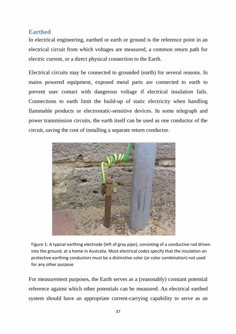
Figure 1: A typical earthing electrode (left of gray pipe), consisting of a conductive rod driven
into the ground, at a home in Australia. Most electrical codes specify that the insulation on
protective earthing conductors must be a distinctive color (or color combination) not used
for any other purpose

38
adequate zero-voltage reference level. In electronic circuit theory, a "earthed" is
usually idealized as an infinite source or sink for charge, which can absorb an
unlimited amount of current without changing its potential. Where a real earthed
connection has a significant resistance, the approximation of zero potential is no
longer valid. Stray voltages or earth potential rise effects will occur, which may
create noise in signals or if large enough will produce an electric shock hazard.
The use of the term grounded (or earth) is so common in electrical and
electronics applications that circuits in portable electronic devices such as cell
phones and media players as well as circuits in vehicles may be spoken of as
having a "earthed" connection without any actual connection to the Earth,
despite "common" being a more appropriate term for such a connection. This is
usually a large conductor attached to one side of the power supply (such as the
"earthed plane" on a printed circuit board) which serves as the common return
path for current from many different components in the circuit.
History
Long-distance electromagnetic telegraph
systems from 1820 onwards[citation needed]
used two or more wires to carry the signal and
return currents. It was then discovered,
probably by the German scientist Carl August
Steinheil in 1836–1837,[1] that the ground
could be used as the return path to complete the
circuit, making the return wire unnecessary.
However, there were problems with this
system, exemplified by the transcontinental
telegraph line constructed in 1861 by the Western Union Company between
Saint Joseph, Missouri, and Sacramento, California. During dry weather, the

39
ground connection often developed a high resistance, requiring water to be
poured on the ground rod to enable the telegraph to work or phones to ring.
Later, when telephony began to replace telegraphy, it was found that the
currents in the earth induced by power systems, electrical railways, other
telephone and telegraph circuits, and natural sources including lightning caused
unacceptable interference to the audio signals, and the two-wire or 'metallic
circuit' system was reintroduced around 1883.
WHY GROUND?
There are several important reasons why a grounding system should be
installed. But the most important reason is to:
Protect people!
Secondary reasons include protection of structures and equipment from
unintentional contact with energized electrical lines.
Signal shielding (electrical noise reduction).
The grounding system must ensure maximum safety from electrical system
faults and lightning. A good grounding system must receive periodic inspection
and maintenance, if needed, to retain its effectiveness. Continued or periodic
maintenance is aided through adequate design, choice of materials and proper
installation techniques to ensure that the grounding system resists deterioration
or inadvertent destruction. Therefore, minimal repair is needed to retain
effectiveness throughout the life of the structure. The grounding system serves
three primary functions which are listed below.
Personnel Safety:
Personnel safety is provided by low impedance grounding and bonding between
metallic equipment, chassis, piping, and other conductive objects so that
currents, due to faults or lightning, do not result in voltages sufficient to cause a

40
shock hazard. Proper grounding facilitates the operation of the overcurrent
protective device protecting the circuit.
Equipment and Building Protection:
Equipment and building protection is provided by low impedance grounding
and bonding between electrical services, protective devices, equipment and
other conductive objects so that faults or lightning currents do not result in
hazardous voltages within the building. Also, the proper operation of
overcurrent protective devices is frequently dependent upon low impedance
fault current paths.
Electrical Noise Reduction:
Proper grounding aids in electrical noise reduction and ensures:
1. The impedance between the signal ground points throughout the building
is minimized.
2. The voltage potentials between interconnected equipment are minimized.
3. That the effects of electrical and magnetic field coupling are minimized.
Another function of the grounding system is to provide a reference for circuit
conductors to stabilize their voltage to ground during normal operation. The
earth itself is not essential to provide a reference function. Another suitable
conductive body may be used instead. The function of a grounding electrode
system and a ground terminal is to provide a system of conductors which
ensures electrical contact with the earth.[2]
In summary there are two main purpose of grounding: signal and safety
rounding. Signal grounding requires the same voltage reference for different
parts of the signal system. Proper signal grounding will minimize conductive,
electromagnetic, magnetic (inductive) or electric (capacitive) noise coupling on
the signals. The main purpose of safety grounding is to eliminate voltage
differences between surfaces that may become energized and therefore present a

41
shock hazard to the people operating the equipment [3]. Another purpose of
safety grounding is to protect the equipment by providing a low impedance path
to the ground in the case of large power surges due to the lightning strikes (earth
grounding). It is important to mention the difference between the Safety and
Earth Grounding. This difference is demonstrated in Figure 2.
Figure 2 safety and earth ground
In order to remove dangerous voltage due to a ground fault, an overcurrent
protection device needs to open quickly. In order to open a fuse or a breaker
quickly, the ground connection must have an impedance low enough to permit
ground fault current to reach a level several times larger than the overcurrent
protection devices rating. Safety ground connection as shown in Figure 1a will
provide that low impedance ground connection. Earth ground provides a
connection to the ground of sufficiently low impedance to prevent the
destruction of the equipment or electric shock which can occur due to
superimposed voltages from lightning strikes. Earth connection however does
not have low enough impedance to draw large currents needed to open the
circuit breaker [3].
Safety grounding as described above is not required for metal parts of
equipment that operates at 50V or less (which is the case for almost all of
Nanometrics equipment installed at the remote sites).

42
Types of grounding
As noted above, grounding and bonding are not the same. In addition, not all
grounding is the same. There are various types of grounding and bonding that
are widely used in the electrical industry. Topics of primary interest are:
• Power System Grounding Including The “Service Entrance”
• Bonding
• Grounding Electrical Equipment
• Lightning Protection
• Protection Of Electronic Equipment (Shielding)
Grounding is a very complex subject. The proper installation of grounding
systems requires knowledge of soil characteristics, grounding conductor
materials and compositions and grounding connections and terminations. A
complete guide to proper grounding is often part of national and international
standards. For example, IEEE Std 80, Guide for Safety in AC Substation
Grounding, is a comprehensive and complex standard for only one particular
grounding application. This standard is needed for proper substation design in
an electric power transmission facility or the power feed to a very large factory.
Smaller facilities can use these design guides also, but such an approach may be
too costly.
Building exterior grounds
It is important to keep in mind that the requirements contained in the NEC
constitute minimum electrical installation requirements. These minimum
requirements cannot ensure that the equipment operated in these buildings will
perform in a satisfactory manner. For these reasons electrical design personnel
often will require additional grounding components. One of the most common
of these consists of a copper conductor that is directly buried in the earth and
installed around the perimeter of the building. The steel building columns are
bonded to this conductor to complete the grounding system.[2]
43
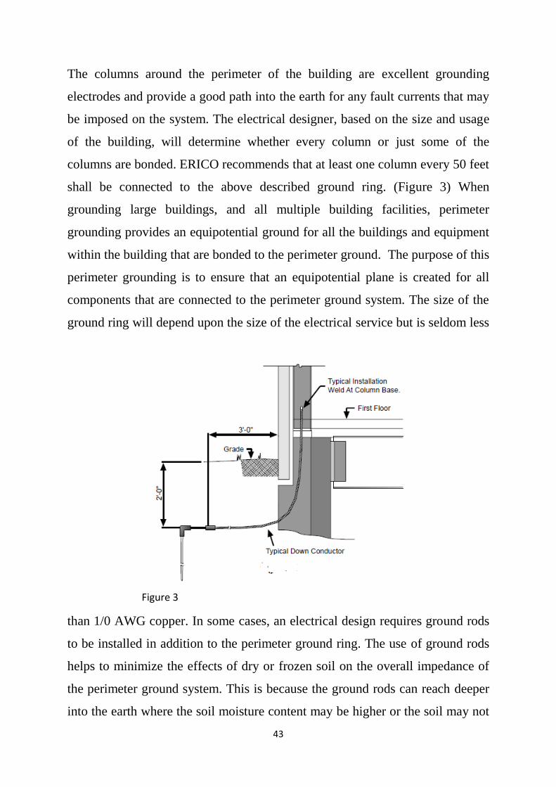
The columns around the perimeter of the building are excellent grounding
electrodes and provide a good path into the earth for any fault currents that may
be imposed on the system. The electrical designer, based on the size and usage
of the building, will determine whether every column or just some of the
columns are bonded. ERICO recommends that at least one column every 50 feet
shall be connected to the above described ground ring. (Figure 3) When
grounding large buildings, and all multiple building facilities, perimeter
grounding provides an equipotential ground for all the buildings and equipment
within the building that are bonded to the perimeter ground. The purpose of this
perimeter grounding is to ensure that an equipotential plane is created for all
components that are connected to the perimeter ground system. The size of the
ground ring will depend upon the size of the electrical service but is seldom less
than 1/0 AWG copper. In some cases, an electrical design requires ground rods
to be installed in addition to the perimeter ground ring. The use of ground rods
helps to minimize the effects of dry or frozen soil on the overall impedance of
the perimeter ground system. This is because the ground rods can reach deeper
into the earth where the soil moisture content may be higher or the soil may not
Figure 3

44
have frozen. ERICO offers a complete line of ground rods from 1/2 inch to 1
inch in diameter to meet the needs of the designer and installer. It is
recommended that the ground ring and ground rods be copper or copperbonded
steel and installed at least 24 inch from the foundation footer and 18 inch
outside the roof drip line. This location will allow for the greatest use of the
water coming off of the roof to maintain a good soil moisture content.
Although less common than in the past, ―triad‖ ground rod arrangements (rods
placed in a triangular configuration) are sometimes specified, usually at the
corners of the building or structure. Figure 4 shows possible conductor/ground
rod configurations. Triad arrangements are not recommended unless the spacing
between the ground rods is equal to or greater than the individual ground rod
Figure 4

45
length. Three rods in a straight line spaced at least equal to the length of the
individual ground rods are more efficient and result in lower overall system
impedance. Installers of these perimeter ground systems need to provide a
―water stop‖ for each grounding conductor that passes through a foundation
wall. This is especially important when the grounding conductor passes through
the foundation wall at a point.
When ―inspection wells‖ are required to expose points from which to measure
system resistance, several methods are available. Inspection wells are usually
placed over a ground rod. If the grounding conductors do not have to be
disconnected from the rod, the conductors can be welded to the rod, and a
plastic pipe, Figure 5, a clay pipe, Figure 6, or a commercial box, Figure 7, can
be placed over the rod. The plastic pipe also works well when an existing
connection must be repeatedly checked, since it can be custom made in the field
to be installed over an existing connection. If the conductors must be removed
from the rod to enable resistance measurements to be made, either a bolted
connector or lug may be used (Figure 8).
Figure 5

46
Figure 6
Figure 7

47
System grounding or earthing
System grounding or earthing involves the ground connection of power services
and separately derived systems. They include generator, transformers,
uninterruptible power systems (UPS). The system earthing is the intentional
connection of a circuit conductor (typically the neutral on a three phase, four
wire system - Protective earth (PE)) to earth. The purpose of the system
grounding [3] is for electrical safety of personnel and equipment as well as fire
safety reasons. Safety is basically governed by the electrical codes and
standards as adopted by government agencies and commercial entities. System
grounding also impacts the performance of electronic load equipment for
reasons related to the control of the common-mode noise and fault currents,
however the personnel and the equipment protection is the primary task of the
grounding.
Figure 7

48
The grounding of power systems is, from a safety standpoint, oriented to limit
the potential difference between grounded objects, to provide a good operation
of over-current protective devices in case of ground fault, to stabilize the phase
voltages with reference to ground and to limit transient voltages due to lightning
and load switching. There are two basic requirements for grounding power
services and separately derived systems or sources (transformer, generators,
UPSs, etc.). The first requirement is to bond the neutral or secondary grounded
circuit conductor to the equipment grounding terminal or bus. For power
services entrances, the incoming neutral conductor is connected to the
equipment grounds bus in the switchboard by means of the main bonding
jumper. For separately derived sources, the neutral must be bonded to the
equipment grounding terminal or bus. The second requirement is that the
equipment grounding terminal or bus must be connected to the nearest effective
grounded electrode by means of the grounding electrode conductor. To illustrate
the grounding connection of a separately derived source, figure 8 shows the
grounding connection for an isolation transformer. If no effective grounded
electrode or building steel is
available, then the separately
derived source should be
connected to the service
entrance grounding point via a
grounding electrode conductor
installed in the most direct and
shortest path practicable. In the
case that metal interior piping is
present near the separately
derived source, a supplemental
grounding electrode conductor Figure 8

49
should also be installed from the equipment grounding terminal or bus of the
separately derived source to the metal interior water piping.
From a performance standpoint, solidly grounded power systems are
recommended practice to ensure the existence of effective conductive paths for
the return current of filters and surge protective devices connected line to
ground or line to chassis. These filters and surge protective devices may be an
integral part of the electronic load equipment or may be separately mounted
devices located in the building electrical distribution system. It is recommended
in the design to aim at the lowest reasonable impedance between the load
equipment containing a filter or surge protective device and the associated
power system source. Low-inductance wiring methods should also be used.
Grounding Structure Characteristics
When choosing grounding structures there are several things to consider. The
grounding structure obviously has to be an excellent conductor. It also has to
have a ―large‖ surface area compared to the system that is being grounded.
Finally the grounding structure has to be close to the system which is at a
distance of no more than 15m. The actual distance depends on the type and size
of the grounding wire. If the distance between the system and its grounding
structure is larger than 10 - 15m, then due to the resistance in the grounding
wire, there could be a potential difference between the equipment enclosures
and the ground. This would defeat the purpose of the grounding connection.
Another important characteristic of the grounding structure is that it is not part
of any signal current carrying path. There must not be any signal currents
flowing through the grounding structure under normal system operation.
Acceptable earth grounding electrodes include: a metal underground water pipe
in contact with the earth for no less than ten feet, the metal frame of the
building, a minimum 2 AWG bare copper ground ring encircling the building or

50
vault and a ground rod of at least 10 feet in length with no less than 8 feet in
contact with the soil. Building sites will often have several of the above
mentioned grounding electrodes. It is important that if more electrodes are
present they all be bonded together to form a single reference electrode
grounding system. A minimum 6 AWG wire should be used for interconnection
purpose.
GROUND RESISTANCE
While many factors
come into play in
determining the overall
effectiveness of the
grounding system, the
resistance of the earth
itself (earth resistivity)
can significantly impact
the overall impedance of
the grounding system.
Several factors, such as
moisture content, mineral content, soil type, soil contaminants, etc., determine
the overall resistivity of the earth. In general, the higher the soil moisture
content, the lower the soil‘s resistivity. Systems designed for areas which
typically have very dry soil and arid climates may need to use enhancement
materials or other means to achieve lower soil resistivity. It can be reduce earth
resistivity and maintain a low system impedance. Ground resistance is usually
measured using an instrument often called an earth resistance tester. This
instrument includes a voltage source, an ohmmeter to measure resistance
directly and switches to change the instrument‘s resistance range. Installers of

51
grounding systems may be required to measure or otherwise determine the
ground resistance of the system they have installed.
The National Electric Code (NEC), told it requires that a single electrode
consisting of rod, pipe, or plate that does not have a resistance to ground of 25
ohms or less. Multiple electrodes should always be installed so that they are
more than six feet (1.8m) apart. Spacing greater than six feet will increase the
rod efficiency. Proper spacing of the electrodes ensures that the maximum
amount of fault current can be safely discharged into the earth[3].
Conductivity of Different Soil Types
As mentioned in the previous sections, the greatest requirement of the
grounding structure is to provide a low impedance path to the ground for any
stray currents. The impedance of the earth ground depends on the resistance of
the grounding wire used, resistance of the electrode conductors (grounding rod
for example), contact resistance between the electrodes and the adjacent earth
and the resistance of the body of earth surrounding the electrodes. The last two
factors are a property of the soil that the sites are built on. Table 1 lists some
common soils with their average approximate resistivities[5]. This table is
meant as a rough guide to the resistivities of different types of soil. The soils
usually contain more than one of the listed types mixed together.

52
1. Dark top level of soil (a mixture of clay, silt, sand and organic
components).
2. The plasticity of soil increases with the addition of water (high plasticity
– high ability to store and hold water).
3. Poorly graded soil means that all particles are of the same approximate
size and therefore the naturally low density cannot be increased by
compaction.
Resistivity of the soil is influenced by the soil mineral content, moisture and
temperature. Water is a single most important factor in the conductivity
characteristics of a particular soil type. Soils with high plasticity, like clay and
topsoil which can hold water, provide excellent earth grounding. On the other
hand porous soils like non-clayey sands, gravel and sandstone, which are
common soil types in drier climates, are poor conductors and provide bad earth
grounds. The worst conducting soils are igneous and sedimentary rocks due to
their high mineral content and inability to hold water. Soils with high
conductivities require different grounding strategies than soils with low
conductivities.

53
Electric Shock
An electrical shock (electrocution) occurs when two portions of a person‘s body
come in contact with electrical conductors of a circuit which is at different
potentials, thus producing a potential difference across the body. The human
body does have resistance and when the body is connected between two
conductors at different potentials (voltage) a circuit is formed through the body
and current will flow.
When the human body comes in contact with only one conductor, a circuit is
not formed and nothing happens. When the human body comes in contact with
circuit conductors, no matter what the voltage is, there is a potential for harm.
The higher the potential difference the more the damage. The effect of an
electrical shock is a function of what parts of the body come in contact with
each conductor, the resistance of each contact point, the surface resistance of the
body at the contact, as well as other factors. When the electrical contact is such
that the circuit path through the body is across the heart, you have the greatest
potential for death. As shown in Figure 1, the human body‘s resistance varies
from as low as 500 ohms to as high as 600,000 ohms. As the skin becomes
moist, the contact resistance drops. If the skin is moist, due to sweat that
contains salt, the resistance drops further. Figure 9 illustrates the amount of
current that can flow through the human body at three different potential
differences across the body. Also shown is the effect of different current levels,
both AC and DC. The ultimate effect is fibrillation, which causes the heart to
stop, and results in death. When a high voltage such as 13,800v is involved, the
body is literally cooked and, at times, explodes. Figure 9 also shows two stick
figures, Safe Sally and Suzie Sizzle to illustrate how the human body can
become electrocuted. The use of female names is only to provide names that are

54
easy to remember and which rhyme with safe and sizzle and in no way intended
to indicate that women are unsafe or more easily shocked[6].
In Figure 10 begins to illustrate how electrical systems can be made safe. We
have used the example of a simple motor circuit to illustrate the basic principle.
It must be understood that there are many ways an electrical system can fail:
transformer winding can short out to the transformers case, motor winding can
short to the motor housing, wires can short to each other or to their
Figure 9

55
surroundings. Many moving items generate static electricity which must be
dealt with.
And it goes on and on. In figure 10 the transformer is shown to be connected to
the earth through a low impedance connection ZL0. This is an intentional ground
which we normally provide, but could also be a high impedance connection. As
shown in Figure 8 virtually everything is connected together.
Figure10

56
In Figure 11 illustrates what happens when a motor winding fails, shorts to its
housing, and a person touches the motor housing while in contact with
something else which is conductive, the I-beam. Suzie Sizzle becomes part of
the circuit. Since impedances are high, the circuit breaker does not open.
Figure 12 shows how the motor should have been installed with a ground
connection to a steel column. In Figure 13 we again have the motor failure. This
time we have Safe Sally. The short circuit current is conducted away through
Figure 11

57
the low impedance path. In this figure we illustrate another problem that of a
high impedance connection between the building steel and the power ground.
Sally will still be safe but the motor will fail. Due to the high impedance, the
fault current will be low and the circuit breaker will not open. Since a part of the
winding is shorted, the motor will overload and will heat up and may even catch
fire. The high impedance shown is often what happens when we rely upon the
earth to be a low impedance ground, which it‘s not always. The same situation
happens when the transformer has a high impedance connection to earth.
Figure 13

58
In most installations today, the circuit conductors are run in metal conduits to
provide physical protection for the conductors, as shown in Figure 14.
Normally the metal conduit is connected to earth and is open bonded to the
ground system for the transformer. The motor is normally not directly
connected to the metal conduit but rather is connected using a flexible
connection that is often made of metal. Figure 15 illustrates what happens when
the flexible connection breaks or makes a poor connection, as often happens.
Figure 16 shows what happens if we connect the conduit directly to the motor.
Fygure14

59
Figure 15
Figure 16

60
Connections break due to vibration and movement of the motor. In Figure 17,
two connections are added. First, the transformer is bonded to the building‘s
structural steel. Second, the motor is also bonded to structural steel. In this
example, Sally is Safe. Figure 18 shows the use of a bonding jumper and Figure
19 shows running a ground wire with the circuit conductors. Conduit
connections, particularly the flexible conduit type, break far too often. The
National Electrical Code requires either a bonding jumper around flexible
connections to motors or a ground conductor be run with the phase
conductors.[6]
Figure 17

61
Figure 18
Figure 19

62
Lightning - an overview
Lightning is an electrical discharge within clouds, from cloud to cloud, or from
cloud to the earth. Lightning protection systems are required to safeguard
against damage or injury caused by lightning or by currents induced in the earth
from lightning.
Clouds can be charged with ten to hundreds of millions of volts in relation to
earth. The charge can be either negative or positive, although negative charged
clouds account for 98% of lightning strikes to earth. The earth beneath a
charged cloud becomes charged to the opposite polarity. As a negatively
charged cloud passes, the excess of electrons in the cloud repels the negative
electrons in the earth, causing the earth‘s surface below the cloud to become
positively charged. Conversely, a positively charged cloud causes the earth
below to be negatively charged. While only about 2% of the lightning strikes to
earth originate from positively charged clouds, these strikes usually have higher

63
currents than those from negatively charged clouds. Lightning protection
systems must be designed to handle maximum currents.
The air between cloud and earth is the dielectric, or insulating medium, that
prevents flash over. When the voltage withstand capability of the air is
exceeded, the air becomes ionized.
Conduction of the discharge takes place in a series of discrete steps. First, a low
current leader of about 100 amperes extends down from the cloud, jumping in a
series of zigzag steps, about 100 to 150 feet (30 to 45 m) each, toward the earth.
As the leader or leaders (there may be more than one) near the earth, a streamer
of opposite polarity rises from the earth or from some object on the earth. When
the two meet, a return stroke of very high current follows the ionized path to the

64
cloud, resulting in the bright flash called lightning. One or more return strokes
make up the flash.
Lightning current, ranging from thousands to hundreds of thousands of amperes,
heats the air which expands with explosive force, and creates pressures that can
exceed 10 atmospheres. This expansion causes thunder, and can be powerful
enough to damage buildings.
Lightning is the nemesis of communication stations, signal circuits, tall
structures and other buildings housing electronic equipment. In addition to
direct strike problems, modern electronics and circuitry are also highly
susceptible to damage from lightning surges and transients. These may arrive
via power, telecommunications and signal lines, even though the lightning strike
may be some distance from the building or installation.[2]
Lightning protection
Lightning protection systems offer protection against both direct and indirect
effects of lightning. The direct effects are burning, blasting, fires and
electrocution. The indirect effects are the disoperation of control or other
electronic equipment due to electrical transients. The major purpose of lightning

65
protection systems is to conduct the high current lightning discharges safely into
the earth.
A well-designed system will minimize voltage differences between areas of a
building or facility and afford maximum protection to people. Direct or
electromagnetically induced voltages can affect power, signal and data cables
and cause significant voltage changes in the grounding system. A well-designed
grounding, bonding and surge voltage protection system can control and
minimize these effects. Since Ben Franklin and other early studiers of lightning,
there have been two camps of thought regarding the performance of direct strike
lightning protection systems. Some believe that a pointed lightning rod or air
terminal will help prevent lightning from striking in the immediate vicinity
because it will help reduce the difference in potential between earth and cloud
by "bleeding off" charge and therefore reducing the chance of a direct strike.
Others believe that air terminals can be attractors of lightning by offering a
more electrically attractive path for a developing direct strike than those other
points on the surface of the earth that would be competing for it. These two
thought "camps" form the two ends of a continuum upon which you can place
just about any of the direct strike lightning protection theories.

66
Active attraction systems
On the left we have systems that are designed to
attract the lightning strike. The theory behind this
practice is to attract the lightning to a known and
preferred point therefore protecting nearby non-
preferred points. The most common way this is done
is to have an air terminal that initiates a streamer
that will intercept the lightning down stroke leader
with a pre-ionized path that will be the most
attractive for the main lightning energy to follow.
Passive neutral systems
The middle of the continuum represents the conventional or traditional theory of
direct strike protection. Conductors are positioned on a structure in the places
where lightning is most likely to strike should a strike occur. We have labeled
these systems as neutral since the air terminal or strike termination devices
themselves aren‘t considered to be any more attractive or unattractive to the
lightning stroke then the surrounding structure. They are positioned where they
should be the first conductor in any path that the lightning strike takes to the
structure.
Active prevention systems
The right third of the continuum is where we find the systems that are designed
to prevent the propagation of a direct stroke of lightning in the area where they
are positioned. There are two theories as to how preventative power occurs.
The first is the ―bleed off ―theory mentioned previously. The second is that the
sharp points on the prevention devices form a corona cloud above them that

67
makes the device an unattractive path to the lightning stroke. There are some
commonalities in these three approaches. Each system‘s design requires the
following:
1. The air terminal or strike termination device must be positioned so that it
is the highest point on the structure.
2. The lightning protection system must be solidly and permanently
grounded. Poor or high resistance connections to ground are the leading
cause of lightning system failure for each one of these systems.
To go further in our comparison, we must separate the prevention systems from
the other two. Obviously, if you are counting on preventing a lightning stroke
from arriving near you, you don‘t have to worry about how to deal with the
lightning current once you have it on your lightning protection system. None of
these systems claims to protect against 100% of the possibility of a lightning
stroke arriving near you. A compromise must be made between protection and
economics.
There is general agreement that the best theoretical lightning system is a solid
faraday cage around whatever it is that is being protected. An airplane is an
example of this. But even in the case of the airplane, there are incidents reported
of damage from direct lightning strokes. On the ground, a complete faraday
cage solidly tied to ground is an attractive protection scheme, but is expensive
to accomplish. If it is a general area, and not a structure that you are trying to
protect, the faraday cage approach is very impractical. While lightning cannot
be prevented, it is possible to design a lightning protection system that will
prevent injury to people and damage to installations in the majority of lightning
strikes. Protection for 100% of the lightning strikes is usually cost prohibitive.
Meeting the codes and standards does not necessarily provide protection to
sensitive electronic equipment and data interconnections. These can be damaged

68
or affected by voltage levels below those that will harm people or start fires. A
well-designed lightning system exceeds the minimum code requirements,
providing not only safety to people and protection against fire, but also
providing protection for equipment and the integrity of data and operations.
Manmade structures of steel, concrete or wood are relatively good conductors
compared to the path of lightning through the ionized air. The impedance of a
structure is so low compared to that of the lightning path that the structure has
virtually no effect on the magnitude of the stroke. As a result, lightning can be
considered a constant current source. The current may divide among several
paths to earth, along the outside walls, sides and interior of a structure, reducing
the voltage drop to ground. Better protection is provided by multiple paths to
ground, including the many paths through the steel building structure. All
structural metal items must be bonded. Bolted joints in steel columns are
usually adequately bonded as are properly lapped and tied or mechanical rebar
splices. Effective lightning protection involves the integration of several
concepts and components. In general, lightning protection can be indexed as
follows:
1. Capture the lightning strike on purpose designed lightning terminals at
preferred points.
2. Conduct the strike to ground safely through purpose designed down
conductors.
3. Dissipate the lightning energy into the ground with minimum rise in
ground potential.
4. Eliminate ground loops and differentials by creating a low impedance,
equipotential ground system.
5. Protect equipment from surges and transients on incoming power lines to
prevent equipment damage and costly operational downtime.

69
6. Protect equipment from surges and transients on incoming
telecommunications and signal lines to prevent equipment damage and
costly operational downtime.
A new approach to lightning protection
The overall purpose of a lightning protection system is to protect a facility and
it's inhabitants from the damage of a direct or nearby lightning strike. The best
way to protect is to shunt the lightning energy ―around ―the vital
components/inhabitants of the facility and dissipate that energy into the earth
where it wants to go anyway. The first step in that process is to make sure that
lightning, when approaching the facility, is attracted to the strike termination
devices that have been installed on the structure for that purpose.
The role of a lightning strike termination system is to effectively launch an
upward leader at the appropriate time so that it, more so than any other
competing feature on the structure, becomes the preferred attachment point for
the approaching down leader (lightning strike). As the down leader approaches
the ground, the ambient electric field rapidly escalates to the point where any

70
point on the structures projecting into this
field begin to cause air breakdown and
launch upward streamer currents. If the
ambient field into which such streamers are
emitted is high enough, the partially
ionized streamer will convert to a fully
ionized up-leader. The ability of the air
termination to launch a sustainable up-
leader that will be preferred over any other
point on the structure, determines its
effectiveness as an imminent lightning
attachment point. The Franklin Rod or
conventional approach to lightning protection has served the industry well, but
since its inception over 200
years ago, the nature and scope
of lighting protection has
changed considerably.
Lightning protection then was
principally a defense against
fire. Wooden buildings, when
struck by lightning, would
often burn. Barns and churches
were the main facilities
seeking this protection due to
their height. Today, fire is still
a concern, but not always the main concern. A modern facility of almost any
kind contains electronic equipment and microprocessors. Facility owners are
concerned about avoiding downtime, data loss, personnel injury & equipment

71
damage as well as fire. The materials used to construct facilities have changed
dramatically also. Steel columns and the steel in reinforced concrete compete as
low impedance conductors for lightning energy. The myriad of
electrical/electronic equipment and conductors that crisscross every level of the
facility are at risk just by being near conductors energized from nearby lightning
strikes. The lightning codes of the past don‘t adequately address these issues.
Bonding of down conductors to electrical apparatus within 3 to 6 feet is
required and can add substantial wiring to a facility if there are a lot of down
conductors. Further, the need for lightning protection for these electrically
sophisticated facilities is growing. The amount of knowledge about lightning
has increased dramatically also. Information about the behavior of leaders, the
changing of electrical fields leading up to a strike, the effects of impedance of
various competing down conductors, and diagnostic equipment has all increased
dramatically. This gives today's designers of lightning protection systems a
large advantage over those of just 20 years ago. These technological advances
and market demands for more cost effective lightning protection systems have
prompted many new and novel approaches to
lightning protection. This system enables the
facility owner to use fewer air terminals with
fewer down conductors. The result is:
fewer conductors to bond to nearby
electrical apparatus.
the ability to run downconductors down
through the middle of a building.
less congestion on the roof of a building
(this is especially important when reroofing).
a safer building roof for workers.
the ability to protect open spaces as well as buildings.

72
an overall more cost effective lightning protection system.
Noise in signaling circuits
Noise in communication and signaling circuits is an issue needing careful
consideration while planning and installing a system. Noise can be due to
improper earthing practices. It may also arise from surges due to external or
internal causes and by interference from other nearby circuits. Incorrect earthing
can result in noise due to ground loops. As we see in figure 20.
A and B are two electronic data processing systems with a communication
connection C between them. C is a cable with a metallic screen bonded to the
enclosures of A and B. A and B are grounded to the building grounding system
at points G1 and G2. R G is the resistance between these points. G1 and G2 are
thus forming a ground loop with the cable screen and any current in the ground
bus between G1 and G2 causes a current to flow through the communication
cable screen, in turn resulting in spurious signals and therefore malfunction.
Figure 20

73
Multiple grounding by bonding of the electrical ground wire to the conduits and
the conduits themselves with other building structures and piping is done in
electrical wiring to get a low ground impedance and it has no adverse effect on
power electrical devices. In fact, many codes recommend such practices in the
interest of human safety. However, as shown in the above example, the same
practice can cause problems when applied to noise-sensitive electronic
equipment. Noise can be due to galvanic coupling, electrostatic coupling,
electromagnetic induction or by radio frequency interference. Both normal
signals and surge as well as power frequency currents can affect nearby circuits
with which, they have a coupling. Design of certain types of signal connections
has an inherent problem of galvanic coupling. Electrostatic coupling is
unavoidable due to the prevalence of inter-electrode capacitances especially in
systems handling high-frequency currents. Most power electrical equipment
produce electromagnetic fields. Arcing in the contacts of a switching device
producing electromagnetic radiation or high-frequency components in currents
flowing in a circuit setting up magnetic fields when passing through wiring are
Figure 21

74
examples of such disturbances. This kind of disturbance is called
electromagnetic interference (EMI) (see figure 21). By and large, the equipment
being designed these days have to conform to standards, which aim to reduce
the propagation of EMI as well as mitigating the effects of EMI from nearby
equipment by using appropriate shielding techniques.
Shielding against electrostatic coupling and electromagnetic interference works
differently and should be applied depending on the requirements of the given
situation. The method of grounding the electromagnetic and electrostatic
shield/screen is also important from the point of view of noise. Improperly
grounded shield/screen can introduce noise into signaling and communication
systems, which it is to protect. Since electronic equipment involve the use of
high-frequency signals, the impedance of the grounding system (as against
resistance, which we normally consider) assumes significance. The ground
system design for such equipment must take the impedance aspect into
consideration too. These and other common problems faced in the electrical
systems of today will be dealt in greater detail in subsequent chapters. Remedial
measures to avoid such phenomena from affecting sensitive circuits will also be
discussed. We will also briefly touch upon the subject of harmonics, which are
sometimes a source of noise. Harmonics are voltage/current waveforms of
frequencies, which are multiples of the power frequency. Harmonics are
generated when certain loads connected to the system draw currents that are not
purely sinusoidal in waveform (such non-sinusoidal current waveforms can be
resolved into a number of sinusoidal waveforms of the fundamental power
frequency and its multiples). Many of the modern devices using semiconductor
components belong to this type and constitute what are called non-linear loads.
Harmonic current being of higher frequencies causes audible hum in
communication circuits and can interfere with low amplitude signals. They also

75
cause heating in equipment due to higher magnetic loss and failure of capacitor
banks due to higher than normal current flow.
Solutions
Devices called ―ground isolators‖ solve the fundamental problem with
unbalanced interfaces. They are differential responding devices with high
common-mode rejection. An isolator is NOT A FILTER that can magically
recognize and remove noise when placed anywhere in the signal path. In order
to solve the problem, an isolator must be installed in the signal path at the point
where the noise coupling actually occurs.
Transformers make excellent ground isolators. They transfer signal voltage
from winding to winding without any electrical connection between them. This
opens the path of the noise current that would otherwise flow between devices.
In theory, since no noise current flows in the cable, noise coupling is completely
eliminated. But in practice, the reduction in ground noise depends critically on
the type of transformer used. There are two basic types of audio transformers.
The first type, known as output, puts primary and secondary windings very
close together. The considerable capacitance thus formed allows noise current to
couple between windings, especially at higher audio frequencies. Of course, this
current couples noise into the signal as it flows in the cable shield. The second
type, known as input, places a shield between the windings. Called a Faraday

76
shield (not a magnetic shield), it effectively eliminates the capacitive coupling
between windings, vastly improving noise rejection.
The graph shows noise rejection versus frequency for a typical unbalanced
interface. The output impedance of device A is 600 Ω and the input impedance
of device B is 50 kΩ. By definition, without an isolator, there is 0 dB of ejection
in an unbalanced interface as shown by the upper plot. The middle plot shows a
typical isolator using an output transformer. Although it reduces 60 Hz hum by
70 dB, buzz artifacts around 3 kHz are reduced by only 35 dB. The lower plot
shows a typical isolator using an input transformer. Its rejection is over 100 dB
at 60 Hz and over 65 dB at 3 kHz.

77
High frequency grounding configuration
The grounding configurations described above provides the necessary
connections to ensure the overall electrical safety of the system. When two or
more components of an interconnected system are installed in an area where
there is a physical space between them and across their separation data
input/output cables and inter-unit power circuit cables (DC, AC or both) are
routed, there exist indirect bounding problems ranging from DC to several tens
of MHz or higher that can compromise the system performance. A reasonable
grounding system has to be designed, without compromising electrical safety,
by defining a ground reference structure over a broad range of frequencies. For
separated equipment or units is necessary to place all of them on a single sheet
of metal in the form of a signal reference plane and then to use direct grounding
or bonding techniques to connect the entire perimeter of the base of the unit to
signal reference structures (SRS). These reference structures can be built as
reference planes (RP) or grid structures (GS). Linear brazing or welding around
the perimeter of the unit‘s base is one method for grounding to the structures.
However, such direct connections are not often practical, and the next best
approach is to use multiple indirect bonding straps of minimized length to
connect individually the plane to each unit locally. The SRS is not intended to
be dielectrically or galvanically insulated or isolated from the safety grounding
conductor (PE) system that is part of the fault/personnel protection grounding
system. The principal purposes of the SRS are:
• To enhance the reliability of signal transfer between interconnected items of
equipment by reducing inter-unit common electrical noise over a broad band of
frequency.
• To prevent damage to inter-unit signal circuits by providing a low-inductance,
and hence, effective ground reference for all of the externally installed AC and

78
DC power, telecommunications, or other signal level, line to ground/chassis
connected equipment that may be used with the associated equipment.
• To prevent or minimize damage to inter-unit signal circuits and equipment
power supplies when a power system ground fault event occurs.

79
Chapter 4
ELECTROMAGNETIC Coupling
Introduction:
Accurate modeling of coupling paths requires solving Maxwell‘s equations,
which are differential equations containing the derivatives of the electric and
magnetic fields with
respect to time and with
respect to three orthogonal
spatial variables. The main
difficulty arises from
complicated boundary
conditions affecting these
equations, since at the
interface between two
media, the E and H fields can be discontinuous. To overcome this difficulty, the
space dependency of E and H is often neglected, analysis being carried out only
in the time domain (which is accurate for systems of small electrical length). In
this way, approximate solutions (as functions of time) are delivered. From a
conceptual point of view, this approach is equivalent to adopting the following
assumptions
All electric fields are confined inside capacitors,
All magnetic fields are confined inside inductors,
Dimensions of the circuit are small compared to the signal wavelength(s).
Hence, the coupling paths (which are actually distributed elements) are
represented by means of their lumped equivalents. Besides a considerable

80
simplification of the problem, the expected benefit is clarify how interference
depends on the system parameters, layout, or package. This information is not
available from the solution of Maxwell‘s equations, even if accurately solving
them were possible. Of course, the drawback of this approach is the limited
accuracy of the solution (but it should be remembered that the ultimate goal of
analysis is to check that the perturbation does not exceed an imposed threshold,
rather than finding an exact solution!).
In this chapter I will covers the coupling mechanisms that occur between fields
and cables, and between cables (crosstalk), both unshielded and shielded cables
are considered.[14]
Methods of Noise Coupling
Coupling Paths
Coupling paths can be grouped under two categories: conduction paths and
radiation paths. The electrical power lines represent the traditional example of
conductive coupling, especially when both the aggressor and victim share the
same power line. An illustration of both categories is shown in this figure,
where the perturbations generated by the motor are transported by the
distribution network to the victim (radio receiver). The radiation path transports
the perturbation produced by the ignition system of a nearby car engine to the
antenna of the receiver through free-space.

81
Conducted Noise
This kind of noise (also called conducted interference) is due to interfering
signals that can propagate from source to victim via a conductive path.
Depending upon the kind of conductive path involved, the commonest practical
situations include:
AC Power Lines
Consider the typical situation in which two different pieces of equipment
connected to adjacent outlets share the same AC line
Where Zi1, Zi2 represent the impedances of the mains lines, which can on the
average be approximated by 50Ω resistances in parallel with 50 μH inductances.
Zt is the impedance seen in the secondary of the transformer and Vp2 represents
the perturbations produced by the source. Applying the voltage divider formula,
the amount of perturbing voltage reaching equipment 1 is
Vp1 = Vp2 (2Zi1 +Zt)/ 2(Zi1 +Zi2) + Zt
Note that Vp1 increases when Zi2 is reduced (i.e., when the separating distance
between the two units decreases). When Zi2<< Zi1, Vp1∼= Vp2 and there is no
attenuation of perturbations reaching the victim. The only remedy is to insert
filters at the AC terminals of equipment 1.
Common Ground Impedance
Another type of conductive coupling is by means of a common ground
impedance. Consider two amplifiers, where M1, M2 are respectively a signal
ground and the ground plane of the equipment. The connection between them is
achieved by a short wire (or strip), which, at low frequency, acts like a short
circuit. However, at higher frequencies the parasitic self inductance (L) of this
wire and its associated resistance (R) give rise to an impedance which is no
longer negligible.

82
Maxwell’s Equation and Electromagnetic Coupling Principle
A transmission line representing a system of N+1 non-touching conductors,
where one of the conductors acts as the reference of zero potential (in other
words, N transmission lines with a common reference placed in proximity to
each other) can generally support N independent, or normal, propagation modes,
each one described with a unique propagation constant and nonzero voltages
and currents. When the media, where the system is located is homogeneous, i.e.
electromagnetic waves propagating along the conductors do not experience
refraction, the modes will be transverse electromagnetic (TEM) and they, still
being independent, will have identical propagation constants. When one of the
N transmission lines is excited with a time-varying signal, N sets of voltages
and currents will be excited in the system due to the electromagnetic coupling.
The essence of the electromagnetic coupling may be readily seen from
Faraday‘s Law stating that any change in the magnetic environment produces
opposing electromotive force:
∮
∮
where electric field intensity E is tangential to contour C and normal to
magnetic flux density B passing through an arbitrary surface S bounded by C.
For a stationary system, counteracting electromotive force will be induced by
any temporal change of perpendicular magnetic field. Written in terms of field

83
components after performing vector operations, Faraday‘s Law may be
presented as follows:
∮
∮
Where Et and Bn are mutually orthogonal components of electric and magnetic
fields respectively. One of the implications of above equation is that if there are
two closely spaced conductors and the first one is acted upon by magnetic field
produced by current in the second conductor, there will be induced
electromotive force emf causing flow of current in the first conductor in the
direction opposing the change of magnetic field. Thus, electromagnetic
coupling is established between the two conductors via magnetic-flux linkage as
shown in Figure bellow.
In case if time-varying magnetic flux is caused by harmonic current, previous
equation may be written in the phasor form as:
∮
Where ω is the operating angular frequency. It is clear from above equation that
in order for electro-magnetic coupling to exist in a stationary system of
conductors, one of them must be driven from an AC source.

84
Review of Directional Couplers
A four port microwave device demonstrating electromagnetic coupling is called
a ―directional coupler‖.
The simplest example of the directional coupler is a pair of unshielded
transmission lines placed closely to each other and having a common reference
of zero potential. Assuming that the lines are identical and the cross section of
the coupled part does not change along its entire length, i.e. the coupled part is
uniform and symmetrical, as shown in Figure above, then the scattering matrix,
[S], of such a network will be as follows, provided the network is ideally
matched to the characteristic impedance of the network at all four ports:
If the network is not built of any nonreciprocal media, it shows reciprocal
properties, which means that any port can serve as input and remaining ports
will serve as appropriate output ports. Depending on the direction that the
coupled wave travels, which in its turn depend on the geometry of the coupler ,
coupled power will appear either at Port 3 or at Port 4 as shown in Figure
above. In the former case, the coupler will be backward-wave, and in the latter –
forward-wave. Assuming a backward-wave directional coupler, i.e. the coupler
where the coupled wave on the secondary line propagates in the direction

85
opposite to the direction of the wave on the primary line, the elements of matrix
above will have the following meaning when Port 1 acts as the input: S12 –
throughput, S13 – coupling, S14 – isolation. By the virtue of reciprocity, the
remaining elements of matrix correspond to the above as follows: S23 = S14, S24
= S13, S34 = S12. So when the input is assigned to Port 1, Port 2 becomes direct
(through) port, Port 3 – coupled port, and Port 4 – isolated. Ideally, no power
should appear at the isolated port or S14 should be zero, i.e. all power should be
divided between the direct and coupled ports with the following relation being
true:
| | | |
In this case, the [S] matrix of the coupler looks like:
Performance of couplers is described with the help of the following four main
parameters:
where P1, P2, P3, and P4 are levels of power at the input, direct, coupled, and
isolated ports respectively. The coupling factor K shows the fraction of input
power that is electromagnetically coupled to the output port; the directivity
factor D indicates the ability of the coupler to isolate between the forward and

86
backward waves, where one of them is the coupled wave de-pending on the
coupler type; and isolation factor I is the measure of the coupler‘s ability to
deter the useful power from traveling to the isolated port. The isolation factor is
linearly connected to the above quantities as follows:
I = K + D, dB
The ideal coupler, as described by [S]-matrix , would have infinite isolation and
directivity.
From the energy conservation law, in order for a network to be lossless its [S]
matrix should be unitary, which means that each matrix column should be
orthogonal to the conjugates of other columns and parallel to its conjugate. It
can be easily seen from two matrixes above that a directional coupler matched
at all four ports is ideally lossless. Complimentarily, it may be inferred from the
energy conservation condition that any lossless, reciprocal four-port network
matched at all ports is a directional coupler. Therefore, directional couplers may
be designed for the condition of being simultaneously lossless, reciprocal, and
matched at all ports. Unlike directional couplers, three-port couplers, such as
Wilkinson coupler, have to be lossy in order to be reciprocal and matched at all
ports.
Two-Line Coupled
Two transmission lines with a common ground, can support two main modes of
propagation, or bimodal propagation. The modes are called ―even mode‖ and
―odd mode‖ [16]. Linear combination of these modes can adequately describe
coupling between uniform symmetric coupled structures see figure below.

87
Even mode exists alone in a coupled-line section when both lines are at the
same potential. In this case, the lines may be said to be separated by the
magnetic wall, which means that the tangential component of the magnetic field
and the normal component of the electric field vanish at the surface of the wall,
while the normal component of the magnetic field and the tangential component
of the electric field remain unchanged while being at the wall interface [17].
The appropriate even-mode field distribution is displayed in Figure below.
Backward-Wave Directional Couplers
The backward-wave directional coupler owes its name to the fact that the
coupled wave on the secondary line propagates in the direction opposite to the
direction of the incident wave on the primary line. The block diagram of the
backward-wave directional coupler and definition of its ports is shown in figure
below.

88
The necessary condition for the backward-wave directional coupler is the
following balance of characteristic impedances:
√
where Z0 is the characteristic impedance to which the coupled lines are
terminated, Z0e and Z0o are the even-mode and odd-mode characteristic
impedances of the coupled lines
Comparison of Tight Directional Couplers
Many applications, such as balanced mixers and amplifiers, require hybrid, or 3-
dB cou-plers. It is difficult to reach this tight level of coupling in couplers
realized in planar waveguiding media since very small gaps are required
between the lines. Therefore, other types of couplers have to be used in order to
obtain the tight levels of coupling. These usually include (1) branch-line and
rat-race couplers, (2) interdigital and tandem couplers, (3) multilayer/broadside
couplers, and (4) lumped-element couplers. Presented below is their brief
description and comparison against the coupled-line coupler for usage in small-
scale microwave circuits. The information is derived from [16], where further
reference on these types of couplers may be found.
1. Branch-line and rat-race couplers. These are principally the same types
of couplers differing only in the phase difference between the direct and
coupled ports: 90 degrees for branch-line couplers and 0 or 180 degrees
for rat-race couplers. They represent a pair of transmission lines
interconnected by a pair of shunt branches at their outputs. The length of
all branches in the branch-line coupler makes a quarter of a wavelength.
In the rat-race coupler all branches but one, which is three quarters of a
wavelength, are a quarter of a wavelength long. Required properties of
the couplers are obtained by proper selection of characteristic impedances
of the branches. Comparing these types of couplers with the coupled-line
backward-wave coupler, it should be noted that they are intrinsically
larger in the area occupied on the substrate and they have inconvenient
shapes that are very wasteful of the substrate space. Since all the ports of
these couplers are electrically connected, they do not provide separation
of DC from the input at the coupled port, which prevents them from
usage in some applications. More importantly, the branch-line and rat-
race couplers are perfectly matched at ports only at their centre

89
frequency, at which there is also complete isolation between decoupled
ports. In addition, they are able to
provide phase quadrature between
the signals at the direct and
coupled ports also only at their
centre frequency. The coupled-line
backward-wave coupler satisfies
these properties independently of
the operating frequency. Therefore,
usage of the branch-line and rate-race couplers is limited to the applica-
tions requiring less than about a 20 % frequency bandwidth only. An
example of a branch-line coupler is shown in Figure.
2. Interdigital and tandem couplers. Both types of these couplers reach
tight levels of coupling through increase of the mutual capacitance by
using a greater number of coupled
lines electrically interconnected
with bonding wires. These couplers
intrinsically suffer from a larger
area occupied on the substrate as
well as from the necessity to use
bonding wires adding parasitic
inductances, which limits their ap-
plication in MMICs. An example of an interdigital coupler is shown in
figure.
3. Multilayer/broadside couplers. The main principle employed in these
couplers is creation of a
number of conductors on top
of each other separated by
layers of dielectric. Tight
levels of coupling are
achieved owing to the fact
that the conductors face each
other with their broad sides,
which increases their mutual
capacitance. These couplers require a more involved fabrication
technology capable of creating multiple metal and dielectric layers, with
ensuing consequences such as interconnects between the metal layers

90
prone to parasitic resonances. An example of multi-layer/broadside
coupler is shown in Fig.
4. Lumped-element couplers. These couplers are composed of single
reactive elements. Being the couplers of choice in the applications
operating at frequencies be-low 3 GHz due to their exclusively small
dimensions, they start to exhibit poor quality (Q) factor at higher
frequencies, where their dimension advantage also shrinks.
Braided Shields (Example1)
Most cables are actually shielded with braid rather than with a solid conductor;
see side figure. The advantage
of braid is flexibility, durability,
strength, and long flexes life.
Braids typically provide only
60% to 98% coverage and are
less effective as shields than
solid conductors. Braided
shields usually provide just
slightly reduced electric field
shielding (except at UHF
frequencies) but greatly reduced magnetic field shielding. The reason is that
braid distorts the uniformity of the longitudinal shield current. A braid is
typically from 5 to 30 dB less effective than a solid shield for protecting against
magnetic fields.
At higher frequencies, the effectiveness of the braid decreases even more as a
result of the holes in the braid. Multiple shields offer more protection but at
higher costs and less flexibility. Premium cables with double and even triple
shields, as well as silver-plated copper braid wires, are used in some critical
military, aerospace, and instrumentation applications.
Figure below shows the transfer impedance for a typical braided-shielded cable
normalized to the dc resistance of the shield. The decrease in transfer impedance
around 1 MHz is because of the skin effect of the shield. The subsequent
increase in transfer impedance above 1 MHz is caused by the holes in the braid.
Curves are given for various percentages of coverage of the braid. Loose-weave
braid (lower percentage shield coverage) provides more flexibility, whereas a
tighter weave braid (higher percentage shield coverage) provides better

91
shielding and less flexibility. As can be observed, for the best shielding, the
braid should provide at least 95% coverage.
Cables with thin, solid aluminum-foil shields are available; these cables provide
almost 100% coverage and more effective electric field shielding. They are not
as strong as braid, have a higher shield cutoff frequency because of their higher
resistance, and are difficult (if not impossible) to terminate properly. Shields are
also available that combine a foil shield with a braid. These cables are intended
to take advantage of the best properties of both foil and braid while minimizing
the disadvantages of both. The braid allows proper 3600
termination of the
shield, and the foil covers the holes in the braid. The shielding effectiveness of

92
braid over foil, or double-braid, cable does not start to degrade until about 100
MHz[14].
Spiral Shields (Example2)
A spiral shield next figure is used on cables for one of three reasons, as follows:
reduced manufacturing costs, ease of termination, or increased flexibility. It
consists of a belt of conductors
wrapped around the cable core
(dielectric). The belt usually consists
of from three to seven conductors. Let
us consider the differences between a
spiral shield cable and an ideal, solid,
homogeneous shield cable. In the
solid homogeneous shield cable, the
shield current is longitudinal along the axis of the cable, and the magnetic field
produced by the shield current is circular and external to the shield. In the case
of a spiral shield cable, the shield current follows the spiral and is at an angle f
with respect to the longitudinal axis of the cable, where f is the pitch angle of
the spiral. The total current I in the shield can be decomposed into two
components, one longitudinal along the axis of the cable and the other circular
around the circumference of the cable.
A braided shield cable can be thought of as having two, or more, interwoven
spiral belts of conductor sets woven in opposite direction, such that each belt
alternately passes over then under the other belt. One belt is applied in a
clockwise direction, and the other belt is applied in a counterclockwise
direction. Because of the opposite direction of the lay of the two belts, the
circular components of shield current tend to cancel each other, which leave
only the longitudinal component of the shield current—hence the much better
high-frequency performance of braided shield cables compared with spiral
shield cables [14].
Ribbon Cables Shields (Example3)
A major cost associated with the use of cables is the expense related to the
termination of the cable. The advantage of ribbon cables is that they allow
lowcost multiple terminations, which is the primary reason for using them.
Ribbon cables have a second advantage. They are ‗‗controlled cables‘‘ because
the position and orientation of the wires within the cable is fixed, like the

93
conductors on a printed wiring board. However, a normal wiring harness is a
‗‗random cables‘‘ because the position and orientation of the wires within the
cable is random and varies from one harness to the next. Therefore, the noise
performance of a ‗‗random cable‘‘ can vary from one unit to the next.
The major problem associated with the use of ribbon cables relates to the way
the individual conductors are assigned with respect to signal leads and grounds.
Figure above shows a ribbon cable where one conductor is a ground and all the
remaining conductors are signal leads. This configuration is used because it
minimizes the number of conductors required; however, it has three problems.
First, it produces large loop areas between the signal conductors and their
ground return, which results in radiation and susceptibility. The second problem
is the common impedance coupling produced when all the signal conductors use
the same ground return. The third problem is crosstalk between the individual
conductors—both capacitive and inductive; therefore, this configuration should
seldom be used. If it is used, the single ground should be assigned to one of the
center conductors to minimize the loop areas.
Another configuration we can use on conductor and the other neighbor
conductor as ground and so on, this is better configuration. In this arrangement,
the loop areas are small because each conductor has a separate ground return
next to it. Because each conductor has a separate ground return, common
impedance coupling is eliminated, and the crosstalk between leads is
minimized. This is the preferred configuration for a ribbon cable, even though it
does require twice as many conductors as first configuration. In applications

94
where crosstalk between cables is a problem, two grounds may be required
between signal conductors.

95
References
[1] The Electromagnetic Telegraph ,website:
http://mysite.du.edu/~jcalvert/tel/morse/ morse.htm
[2] Practical Guide to Electrical Grounding, Library Of Congress Catalog Card
Number: 99-72910, 1999 ERICO, Inc.
[3] Nanometrics Equipment Grounding Recommendations , Nanometrics
Systems Engineering, November 3, 2003
[4] P. Van der Laan, M. Van Houten, A. Van Deursen, "A grounding
philosophy", Proc. IEEE Symposium on Electromagnetic compatibility,1955-
1995.
[5] ANSI/IEEE Std 142-1991, ―Green Book,‖ IEEE Recommended Practice for
Grounding of
Industrial and Commercial Power Systems.
[6] John C. Pfeiffer, Principles of Electrical Grounding, 2001
[7] Edward F. Vance, "Coupling to shield cables", 1987
[8] Ravaioli, Fawwaz T. Ulaby, Eric Michielssen, Umberto (2010).
Fundamentals of applied electromagnetics (6th ed.). Boston: Prentice Hall
[9] http://en.wikipedia.org/wiki/Electromagnetism#cite_note-1
[10] http://en.wikipedia.org/wiki/Electromagnetic_field
[11] Bakshi, U. A. and Godse, A. P. (2009). Basic Electronics Engineering.
Technical Publications.
[12] http://en.wikipedia.org/wiki/Noise_(signal_processing)
[13] Electronic Noise and Interfering Signals Principles and Applications, Dr.
Gabriel Vasilescu, springer.
[14] Henry W. Ott, Electromagnetic Compatibility Engineering, 2009, John
Wiley & Sons, Inc.

96
[15] Anatoly Tsaliovich, Electromagnetic Shielding Handbook For Wired And
Wireless Emc Applications, Kluwer Academic Publishers, Boston / London /
Dordrecht
[16] R. Mongia, I. Bahl, P. Bhartia, RF and Microwave Coupled-Line Circuits,
Artech House, Boston, 1999.
[17] D. M. Pozar, Microwave Engineering, Addison-Wesley Publishing
Company, 1990.