electromagnetic wave propagation complex...
TRANSCRIPT
Indraprastha Institute of
Information Technology Delhi ECE230
Lecture – 21 Date: 06.04.2015 • Electromagnetic Wave Propagation • Complex Permittivity, Loss Tangent, Intrinsic
Impedance, Skin Depth, Skin Effect etc. • Electromagnetic Shielding
Indraprastha Institute of
Information Technology Delhi ECE230
Introduction
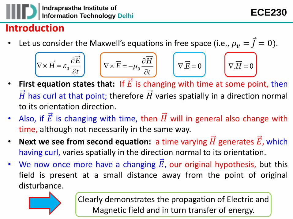
• Let us consider the Maxwell’s equations in free space (i.e., 𝜌𝑣 = 𝐽 = 0).
0
EH
t
0
HE
t
. 0E . 0H
• First equation states that: If 𝐸 is changing with time at some point, then
𝐻 has curl at that point; therefore 𝐻 varies spatially in a direction normal to its orientation direction.
• Also, if 𝐸 is changing with time, then 𝐻 will in general also change with time, although not necessarily in the same way.
• Next we see from second equation: a time varying 𝐻 generates 𝐸, which having curl, varies spatially in the direction normal to its orientation.
• We now once more have a changing 𝐸, our original hypothesis, but this field is present at a small distance away from the point of original disturbance.
Clearly demonstrates the propagation of Electric and Magnetic field and in turn transfer of energy.
Indraprastha Institute of
Information Technology Delhi ECE230
Introduction (contd.)
• The velocity with which this effect moves away from the original point is the velocity of light.
• We postulate the existence of 𝑢𝑛𝑖𝑓𝑜𝑟𝑚 𝑝𝑙𝑎𝑛𝑒 𝑤𝑎𝑣𝑒, in which both fields
𝐸 and 𝐻, lie in the transverse plane → that is, the plane whose normal is the direction of propagation.
A 𝑢𝑛𝑖𝑓𝑜𝑟𝑚 𝑝𝑙𝑎𝑛𝑒 𝑤𝑎𝑣𝑒 is characterized by electric and magnetic fields that have uniform properties at all points
across an infinite plane.
A 𝑝𝑙𝑎𝑛𝑒 𝑤𝑎𝑣𝑒 has no electric or magnetic field components along its direction of propagation
Indraprastha Institute of
Information Technology Delhi ECE230
Introduction (contd.)
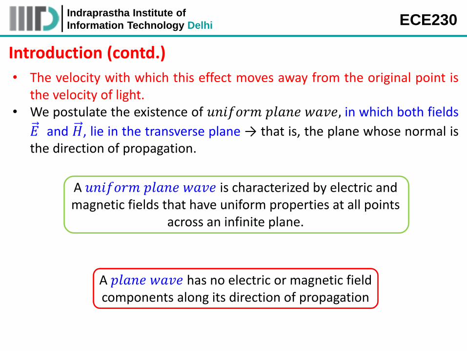
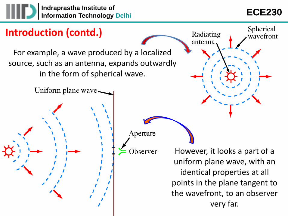
For example, a wave produced by a localized source, such as an antenna, expands outwardly
in the form of spherical wave.
However, it looks a part of a uniform plane wave, with an
identical properties at all points in the plane tangent to the wavefront, to an observer
very far.
Indraprastha Institute of
Information Technology Delhi ECE230
Introduction (contd.)
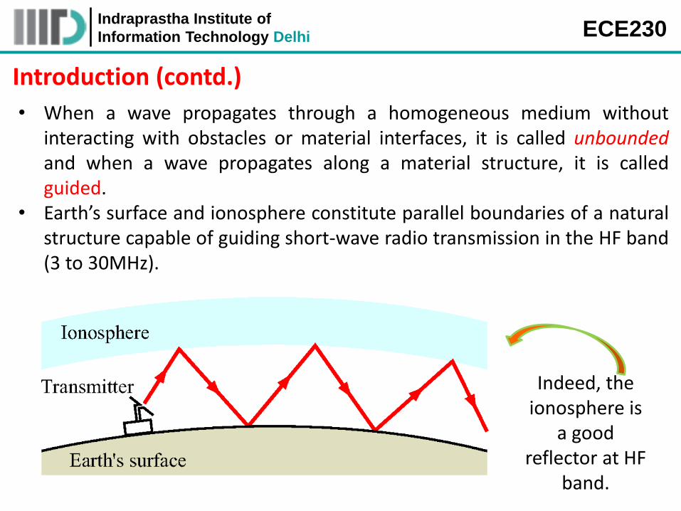
• When a wave propagates through a homogeneous medium without interacting with obstacles or material interfaces, it is called unbounded and when a wave propagates along a material structure, it is called guided.
• Earth’s surface and ionosphere constitute parallel boundaries of a natural structure capable of guiding short-wave radio transmission in the HF band (3 to 30MHz).
Indeed, the ionosphere is
a good reflector at HF
band.
Indraprastha Institute of
Information Technology Delhi ECE230
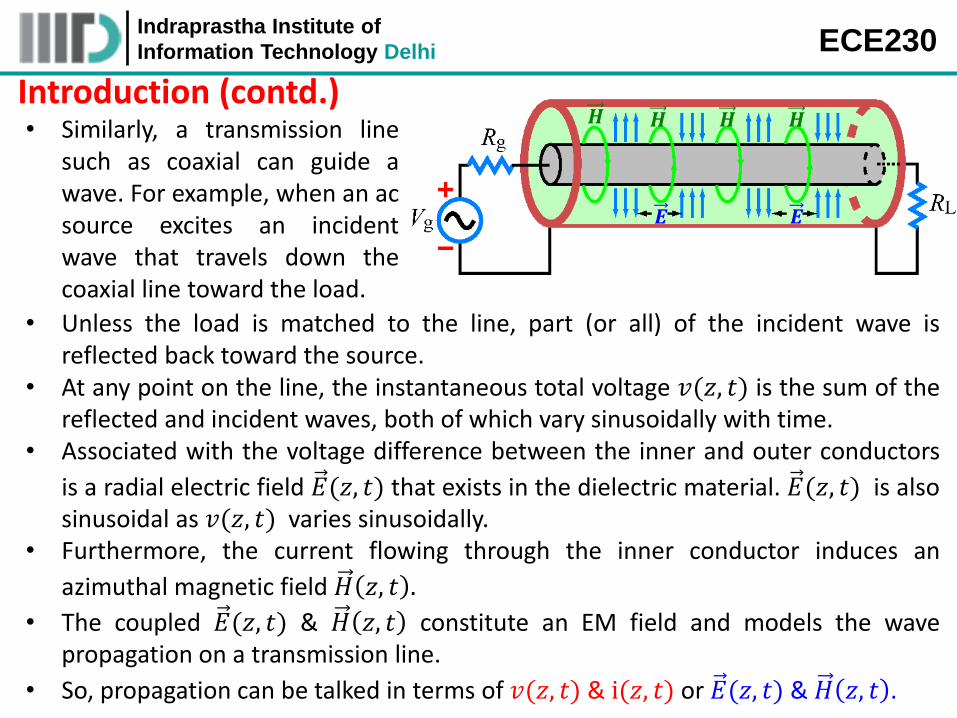
Introduction (contd.) • Similarly, a transmission line
such as coaxial can guide a wave. For example, when an ac source excites an incident wave that travels down the coaxial line toward the load.
𝑬 𝑬
𝑯 𝑯 𝑯 𝑯
• Unless the load is matched to the line, part (or all) of the incident wave is reflected back toward the source.
• At any point on the line, the instantaneous total voltage 𝑣(𝑧, 𝑡) is the sum of the reflected and incident waves, both of which vary sinusoidally with time.
• Associated with the voltage difference between the inner and outer conductors
is a radial electric field 𝐸(𝑧, 𝑡) that exists in the dielectric material. 𝐸(𝑧, 𝑡) is also sinusoidal as 𝑣(𝑧, 𝑡) varies sinusoidally.
• Furthermore, the current flowing through the inner conductor induces an
azimuthal magnetic field 𝐻 𝑧, 𝑡 .
• The coupled 𝐸(𝑧, 𝑡) & 𝐻 𝑧, 𝑡 constitute an EM field and models the wave propagation on a transmission line.
• So, propagation can be talked in terms of 𝑣(𝑧, 𝑡) & i(𝑧, 𝑡) or 𝐸(𝑧, 𝑡) & 𝐻 𝑧, 𝑡 .
Indraprastha Institute of
Information Technology Delhi ECE230
Wave Propagation in Lossy Dielectrics
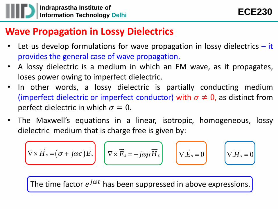
• Let us develop formulations for wave propagation in lossy dielectrics – it provides the general case of wave propagation.
• A lossy dielectric is a medium in which an EM wave, as it propagates, loses power owing to imperfect dielectric.
• In other words, a lossy dielectric is partially conducting medium (imperfect dielectric or imperfect conductor) with 𝜎 ≠ 0, as distinct from perfect dielectric in which 𝜎 = 0.
The time factor 𝑒𝑗𝜔𝑡 has been suppressed in above expressions.
s sH j E s sE j H . 0sE . 0sH
• The Maxwell’s equations in a linear, isotropic, homogeneous, lossy dielectric medium that is charge free is given by:
Indraprastha Institute of
Information Technology Delhi ECE230
Wave Propagation in Lossy Dielectrics (contd.)
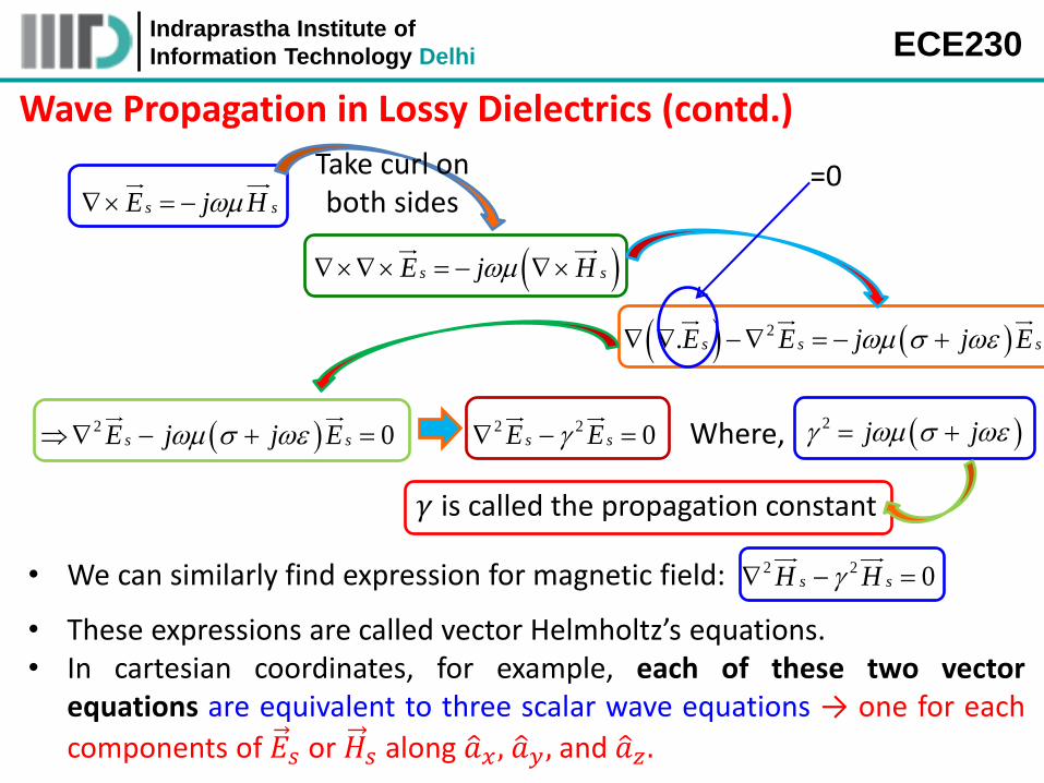
s sE j H
Take curl on both sides
s sE j H
2. s s sE E j j E
=0
2 2 0s sE E 2 j j Where,
𝛾 is called the propagation constant
• We can similarly find expression for magnetic field: 2 2 0s sH H
• These expressions are called vector Helmholtz’s equations. • In cartesian coordinates, for example, each of these two vector
equations are equivalent to three scalar wave equations → one for each
components of 𝐸𝑠 or 𝐻𝑠 along 𝑎 𝑥 , 𝑎 𝑦, and 𝑎 𝑧.
2 0s sE j j E
Indraprastha Institute of
Information Technology Delhi ECE230
Wave Propagation in Lossy Dielectrics (contd.)
2 2 22
2 2 2
sx sx sxsx
E E EE
x y z
2 2 2
2
2 2 2
sy sy sy
sy
E E EE
x y z
2 2 22
2 2 2
sz sz szsz
E E EE
x y z
2 2 22
2 2 2
sx sx sxsx
H H HH
x y z
2 2 2
2
2 2 2
sy sy sy
sy
H H HH
x y z
2 2 22
2 2 2
sz sz szsz
H H HH
x y z
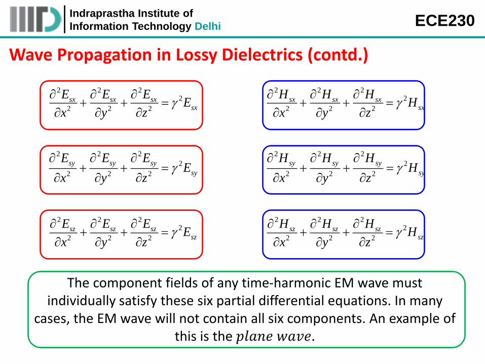
The component fields of any time-harmonic EM wave must individually satisfy these six partial differential equations. In many
cases, the EM wave will not contain all six components. An example of this is the 𝑝𝑙𝑎𝑛𝑒 𝑤𝑎𝑣𝑒.
Indraprastha Institute of
Information Technology Delhi ECE230
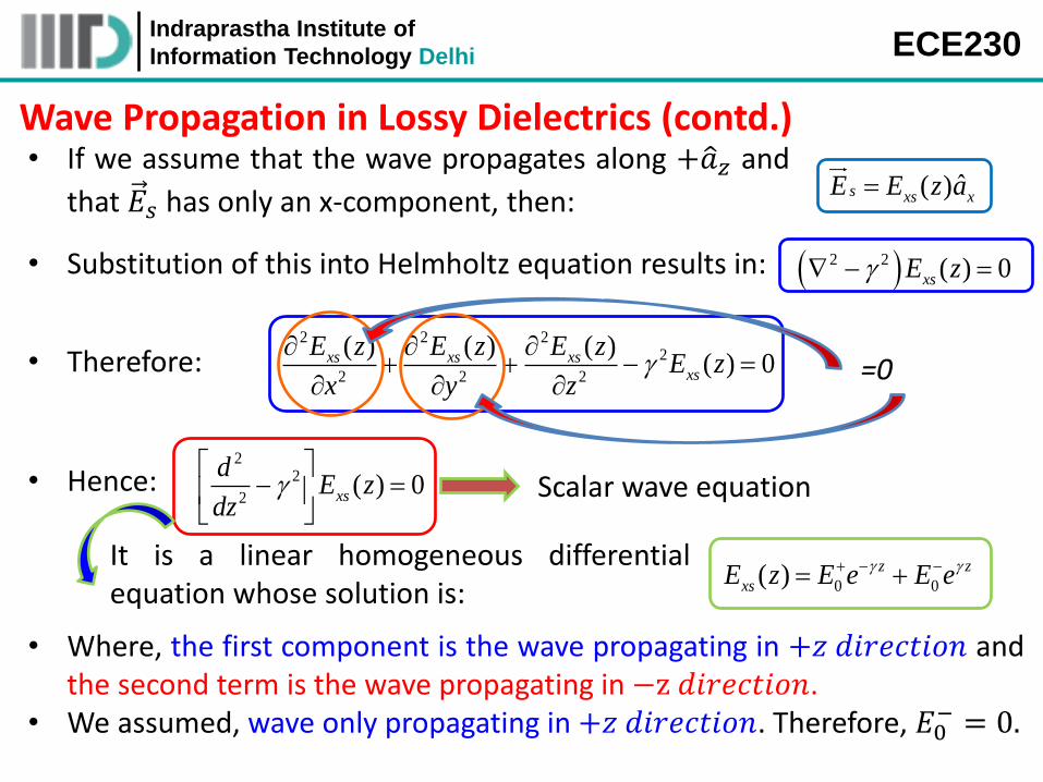
Wave Propagation in Lossy Dielectrics (contd.) • If we assume that the wave propagates along +𝑎 𝑧 and
that 𝐸𝑠 has only an x-component, then: ˆ( )s xs xE E z a
• Substitution of this into Helmholtz equation results in: 2 2 ( ) 0xsE z
• Therefore: 2 2 2
2
2 2 2
( ) ( ) ( )( ) 0xs xs xs
xs
E z E z E zE z
x y z
• Hence: 2
2
2( ) 0xs
dE z
dz
=0
Scalar wave equation
It is a linear homogeneous differential equation whose solution is: 0 0( ) z z
xsE z E e E e
• Where, the first component is the wave propagating in +𝑧 𝑑𝑖𝑟𝑒𝑐𝑡𝑖𝑜𝑛 and the second term is the wave propagating in −z 𝑑𝑖𝑟𝑒𝑐𝑡𝑖𝑜𝑛.
• We assumed, wave only propagating in +𝑧 𝑑𝑖𝑟𝑒𝑐𝑡𝑖𝑜𝑛. Therefore, 𝐸0− = 0.
Indraprastha Institute of
Information Technology Delhi ECE230
Wave Propagation in Lossy Dielectrics (contd.)
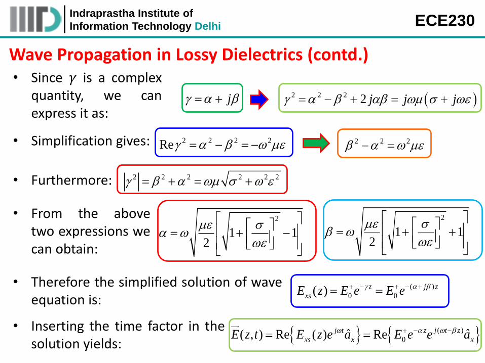
• Simplification gives: 2 2 2 2Re 2 2 2
• Furthermore: 2 2 2 2 2 2
• From the above two expressions we can obtain:
2
1 12
2
1 12
j 2 2 2 2 j j j
• Since 𝛾 is a complex quantity, we can express it as:
( )
0ˆ ˆ( , ) Re ( ) Rej t z j t z
xs x xE z t E z e a E e e a • Inserting the time factor in the
solution yields:
• Therefore the simplified solution of wave equation is:
( )
0 0( ) z j z
xsE z E e E e
Indraprastha Institute of
Information Technology Delhi ECE230
Wave Propagation in Lossy Dielectrics (contd.)
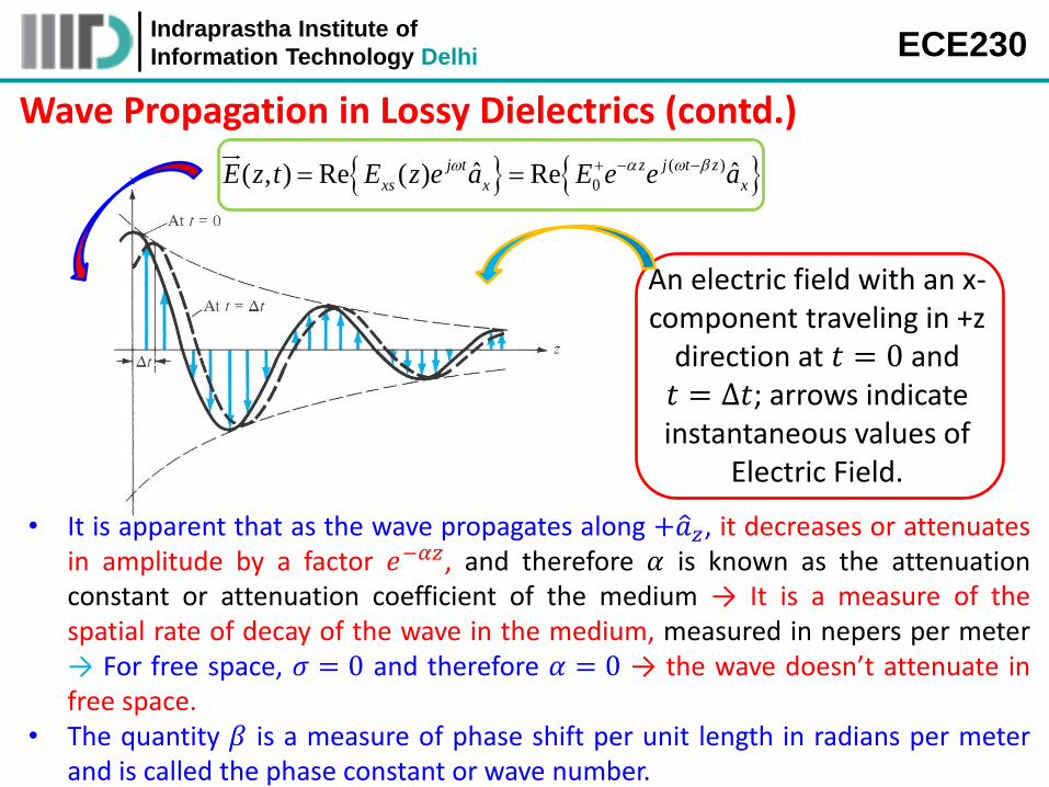
An electric field with an x-component traveling in +z
direction at 𝑡 = 0 and 𝑡 = ∆𝑡; arrows indicate instantaneous values of
Electric Field.
• It is apparent that as the wave propagates along +𝑎 𝑧, it decreases or attenuates in amplitude by a factor 𝑒−𝛼𝑧, and therefore 𝛼 is known as the attenuation constant or attenuation coefficient of the medium → It is a measure of the spatial rate of decay of the wave in the medium, measured in nepers per meter → For free space, 𝜎 = 0 and therefore 𝛼 = 0 → the wave doesn’t attenuate in free space.
• The quantity 𝛽 is a measure of phase shift per unit length in radians per meter and is called the phase constant or wave number.
( )
0ˆ ˆ( , ) Re ( ) Rej t z j t z
xs x xE z t E z e a E e e a

Indraprastha Institute of
Information Technology Delhi ECE230
Wave Propagation in Lossy Dielectrics (contd.)
• The solution for magnetic field is: ( )
0ˆ( , ) Re z j t z
yH z t H e e a
• Where: 0
0
EH
η is a complex quantity known as the
𝑖𝑛𝑡𝑟𝑖𝑛𝑠𝑖𝑐 𝑖𝑚𝑝𝑒𝑑𝑎𝑛𝑐𝑒 of the medium.
j je
j
Derive it !
1/42
/
1
tan 2
0 ≤ 𝜃η ≤ 45°
• Therefore the magnetic field expression is:
( )0 ˆ( , ) Re z j t z
yj
EH z t e e a
e
0 ˆ( , ) cos( )z
y
EH z t e t z a
It is evident that 𝑬 and 𝑯 are out of phase by 𝜽𝜼.
Indraprastha Institute of
Information Technology Delhi ECE230
Wave Propagation in Lossy Dielectrics (contd.)
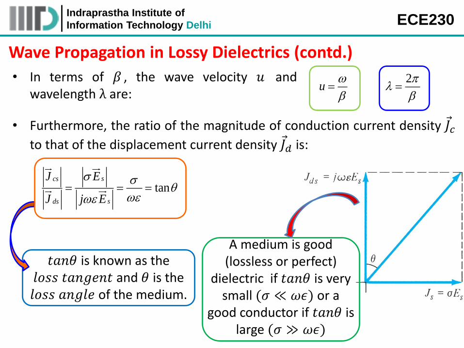
• In terms of 𝛽 , the wave velocity 𝑢 and wavelength λ are:
u
2
𝑡𝑎𝑛𝜃 is known as the 𝑙𝑜𝑠𝑠 𝑡𝑎𝑛𝑔𝑒𝑛𝑡 and 𝜃 is the 𝑙𝑜𝑠𝑠 𝑎𝑛𝑔𝑙𝑒 of the medium.
• Furthermore, the ratio of the magnitude of conduction current density 𝐽 𝑐
to that of the displacement current density 𝐽 𝑑 is:
tanscs
sds
J E
J j E
A medium is good (lossless or perfect)
dielectric if 𝑡𝑎𝑛𝜃 is very small (𝜎 ≪ 𝜔𝜖) or a
good conductor if 𝑡𝑎𝑛𝜃 is large (𝜎 ≫ 𝜔𝜖)
Indraprastha Institute of
Information Technology Delhi ECE230
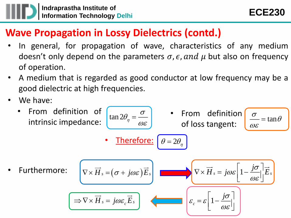
Wave Propagation in Lossy Dielectrics (contd.) • In general, for propagation of wave, characteristics of any medium
doesn’t only depend on the parameters 𝜎, 𝜖, 𝑎𝑛𝑑 𝜇 but also on frequency of operation.
• A medium that is regarded as good conductor at low frequency may be a good dielectric at high frequencies.
• We have:
tan 2
• From definition of intrinsic impedance: tan
• From definition of loss tangent:
• Therefore: 2
s sH j E • Furthermore: 1s s
jH j E
s scH j E 1c
j
Indraprastha Institute of
Information Technology Delhi ECE230
Wave Propagation in Lossy Dielectrics (contd.)
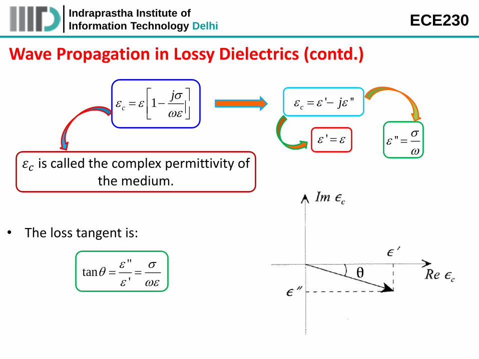
1c
j
' ''c j
' ''
• The loss tangent is:
"tan
'
휀𝑐 is called the complex permittivity of the medium.
Indraprastha Institute of
Information Technology Delhi ECE230
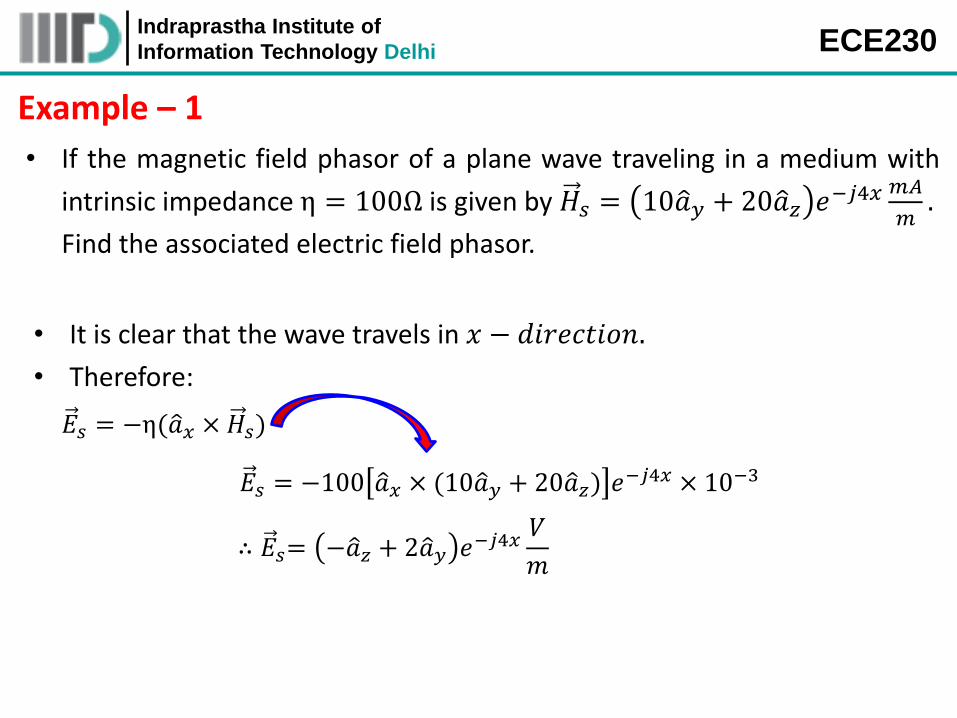
Example – 1
• If the magnetic field phasor of a plane wave traveling in a medium with
intrinsic impedance η = 100Ω is given by 𝐻𝑠 = 10𝑎 𝑦 + 20𝑎 𝑧 𝑒−𝑗4𝑥 𝑚𝐴
𝑚.
Find the associated electric field phasor.
• It is clear that the wave travels in 𝑥 − 𝑑𝑖𝑟𝑒𝑐𝑡𝑖𝑜𝑛.
• Therefore:
𝐸𝑠 = −η(𝑎 𝑥 × 𝐻𝑠)
𝐸𝑠 = −100 𝑎 𝑥 × (10𝑎 𝑦 + 20𝑎 𝑧) 𝑒−𝑗4𝑥 × 10−3
∴ 𝐸𝑠= −𝑎 𝑧 + 2𝑎 𝑦 𝑒−𝑗4𝑥𝑉
𝑚
Indraprastha Institute of
Information Technology Delhi ECE230
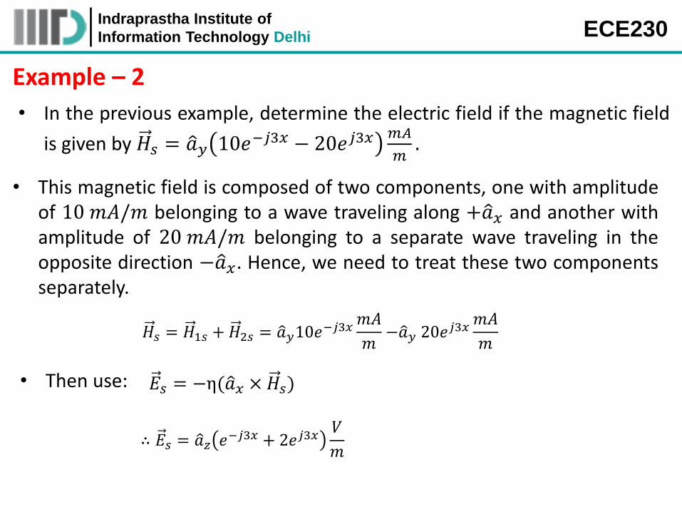
Example – 2
• In the previous example, determine the electric field if the magnetic field
is given by 𝐻𝑠 = 𝑎 𝑦 10𝑒−𝑗3𝑥 − 20𝑒𝑗3𝑥 𝑚𝐴
𝑚.
• This magnetic field is composed of two components, one with amplitude of 10 𝑚𝐴/𝑚 belonging to a wave traveling along +𝑎 𝑥 and another with amplitude of 20 𝑚𝐴/𝑚 belonging to a separate wave traveling in the opposite direction −𝑎 𝑥. Hence, we need to treat these two components separately.
𝐻𝑠 = 𝐻1𝑠 + 𝐻2𝑠 = 𝑎 𝑦10𝑒−𝑗3𝑥
𝑚𝐴
𝑚−𝑎 𝑦 20𝑒𝑗3𝑥
𝑚𝐴
𝑚
𝐸𝑠 = −η(𝑎 𝑥 × 𝐻𝑠) • Then use:
∴ 𝐸𝑠 = 𝑎 𝑧 𝑒−𝑗3𝑥 + 2𝑒𝑗3𝑥𝑉
𝑚
Indraprastha Institute of
Information Technology Delhi ECE230
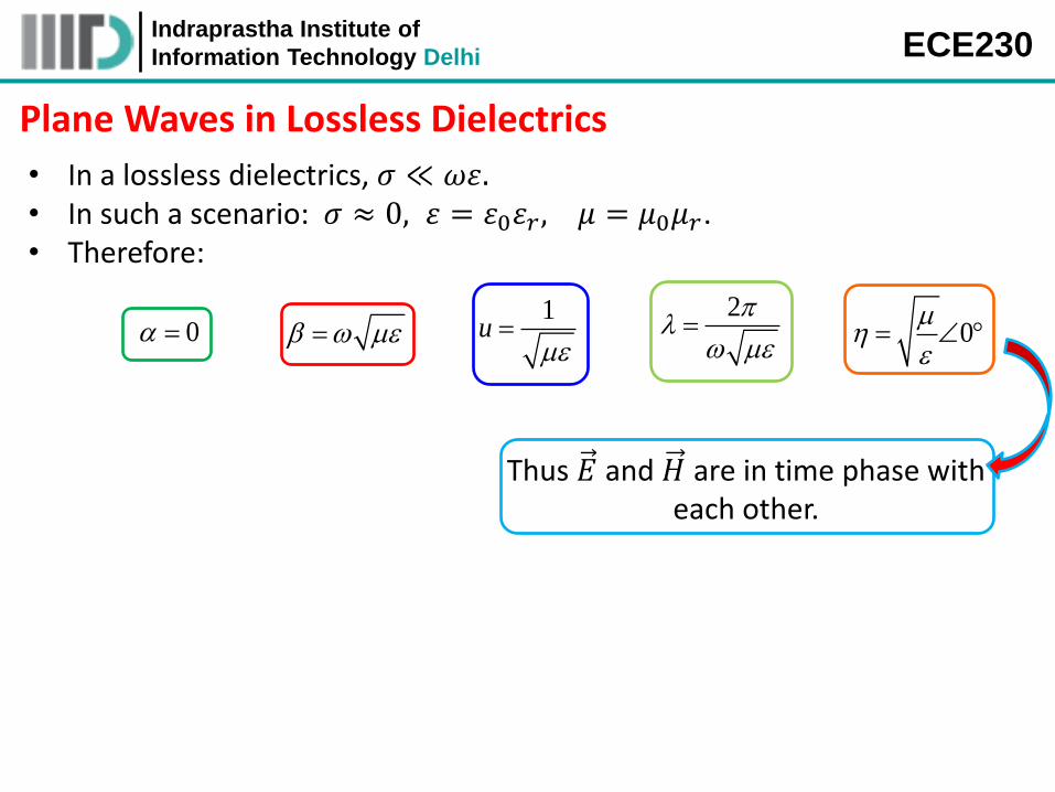
Plane Waves in Lossless Dielectrics
• In a lossless dielectrics, 𝜎 ≪ 𝜔휀. • In such a scenario: 𝜎 ≈ 0, 휀 = 휀0휀𝑟, 𝜇 = 𝜇0𝜇𝑟. • Therefore:
0
0 1
u
2
Thus 𝐸 and 𝐻 are in time phase with each other.
Indraprastha Institute of
Information Technology Delhi ECE230
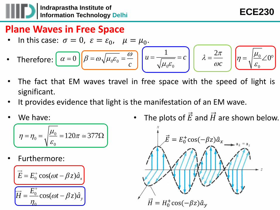
Plane Waves in Free Space • In this case: 𝜎 = 0, 휀 = 휀0, 𝜇 = 𝜇0.
• The fact that EM waves travel in free space with the speed of light is significant.
• It provides evidence that light is the manifestation of an EM wave.
• Furthermore:
0ˆcos( ) xE E t z a
0
0
ˆcos( ) y
EH t z a
0
0
0
0 0 0c
0 0
1u c
2
c
• Therefore:
00
0
120 377
• We have: • The plots of 𝐸 and 𝐻 are shown below.
𝐸 = 𝐸0+cos (−𝛽𝑧)𝑎 𝑥
𝐻 = 𝐻0+cos (−𝛽𝑧)𝑎 𝑦
Indraprastha Institute of
Information Technology Delhi ECE230
Plane Waves in Free Space (contd.) • In general, if 𝑎 𝐸 , 𝑎 𝐻 and 𝑎 𝑘 are unit
vectors along 𝐸 , 𝐻 and the direction of propagation, then:
ˆ ˆ ˆk E Ha a a ˆ ˆ ˆ
k H Ea a a ˆ ˆ ˆE H ka a a
• Both 𝐸 and 𝐻 fields are everywhere normal to the direction of wave propagation.
• It means that the fields lie in a plane that is transverse or orthogonal to the direction of propagation.
• They form an EM wave that has no electric or magnetic field components along the direction of propagation → such a wave is called transverse electromagnetic (TEM) wave.
• A combination of 𝐸 and 𝐻 is called a uniform plane wave because fields have same magnitude throughout any transverse plane.
• The direction in which the electric field points is the polarization of a TEM wave → Essentially, polarization of a uniform plane wave describes the
locus traced by the tip of the 𝐸 vector (in the plane orthogonal to the direction of propagation) at a given point in space as a function of time.
Indraprastha Institute of
Information Technology Delhi ECE230
It illustrates a uniform plane wave
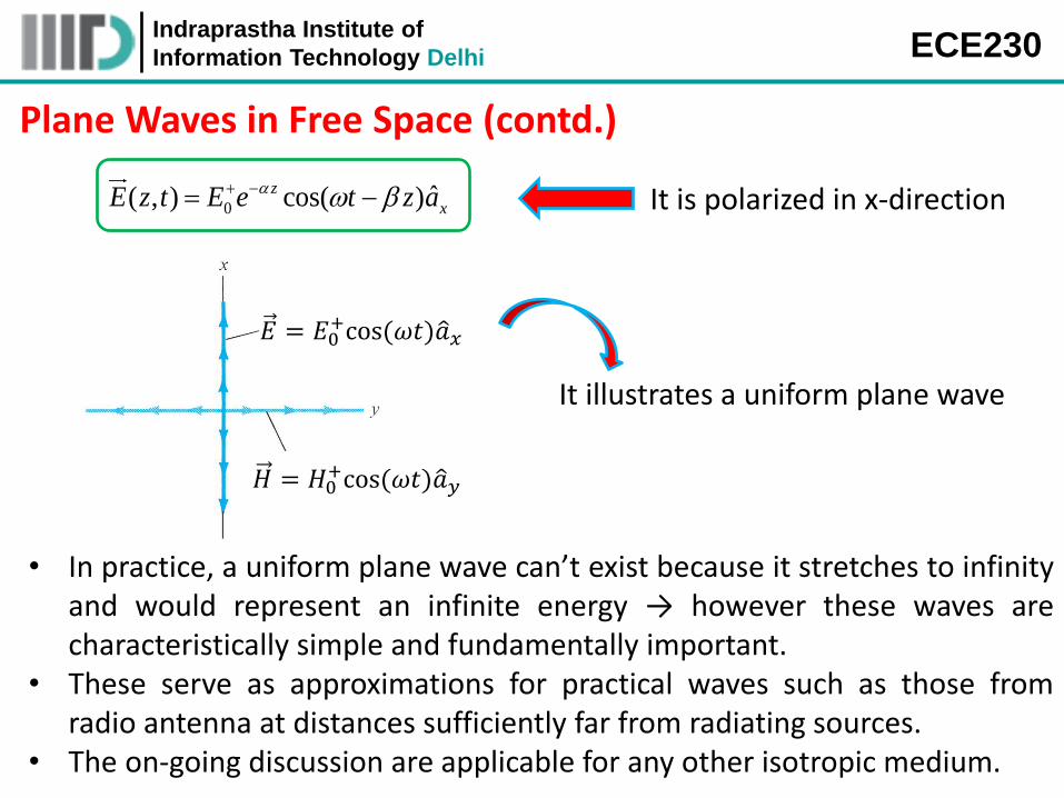
Plane Waves in Free Space (contd.)
0ˆ( , ) cos( )z
xE z t E e t z a It is polarized in x-direction
• In practice, a uniform plane wave can’t exist because it stretches to infinity and would represent an infinite energy → however these waves are characteristically simple and fundamentally important.
• These serve as approximations for practical waves such as those from radio antenna at distances sufficiently far from radiating sources.
• The on-going discussion are applicable for any other isotropic medium.
𝐸 = 𝐸0+cos (𝜔𝑡)𝑎 𝑥
𝐻 = 𝐻0+cos (𝜔𝑡)𝑎 𝑦
Indraprastha Institute of
Information Technology Delhi ECE230
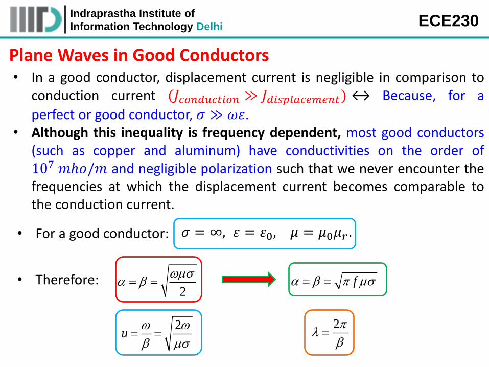
Plane Waves in Good Conductors • In a good conductor, displacement current is negligible in comparison to
conduction current (𝐽𝑐𝑜𝑛𝑑𝑢𝑐𝑡𝑖𝑜𝑛 ≫ 𝐽𝑑𝑖𝑠𝑝𝑙𝑎𝑐𝑒𝑚𝑒𝑛𝑡) ↔ Because, for a
perfect or good conductor, 𝜎 ≫ 𝜔휀. • Although this inequality is frequency dependent, most good conductors
(such as copper and aluminum) have conductivities on the order of 107 𝑚ℎ𝑜/𝑚 and negligible polarization such that we never encounter the frequencies at which the displacement current becomes comparable to the conduction current.
𝜎 = ∞, 휀 = 휀0, 𝜇 = 𝜇0𝜇𝑟. • For a good conductor:
• Therefore: 2
f
2u
2
Indraprastha Institute of
Information Technology Delhi ECE230
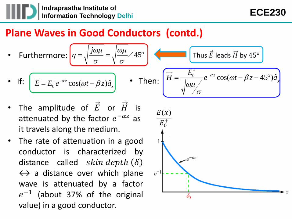
Plane Waves in Good Conductors (contd.)
• Furthermore: 45j
Thus 𝐸 leads 𝐻 by 45°
0ˆcos( )z
xE E e t z a • If: 0 ˆcos( 45 )z
y
EH e t z a
• Then:
𝐸(𝑥)
𝐸0+
• The amplitude of 𝐸 or 𝐻 is attenuated by the factor 𝑒−𝛼𝑧 as it travels along the medium.
• The rate of attenuation in a good conductor is characterized by distance called 𝑠𝑘𝑖𝑛 𝑑𝑒𝑝𝑡ℎ 𝛿 ↔ a distance over which plane wave is attenuated by a factor 𝑒−1 (about 37% of the original value) in a good conductor.

Indraprastha Institute of
Information Technology Delhi ECE230
Plane Waves in Good Conductors (contd.)
1
0 0E e E e 1
• 𝑠𝑘𝑖𝑛 𝑑𝑒𝑝𝑡ℎ is a measure of the depth to which an EM wave can penetrate the medium.
Valid for any material medium
1 1
f
For a partially conducting medium, the skin depth can be considerably large.
• For a good conductor: /41 12 j je
• For good conductors, 𝛼 = 𝛽 =1
𝛿, therefore: /
0ˆcos( )z
x
zE E e t a
Indraprastha Institute of
Information Technology Delhi ECE230
Plane Waves in Good Conductors (contd.)
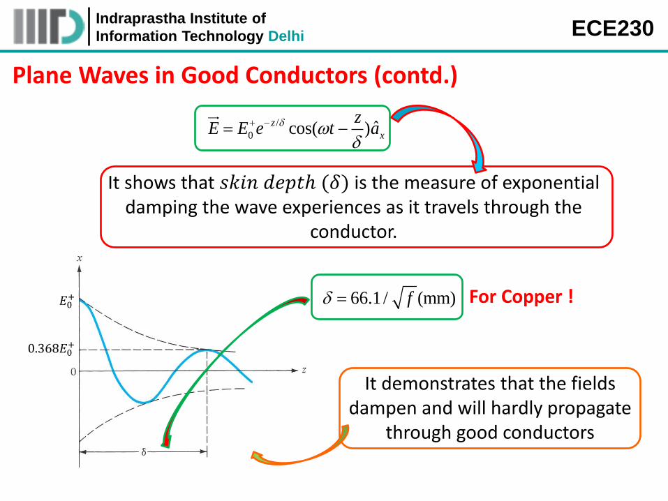
/
0ˆcos( )z
x
zE E e t a
It shows that 𝑠𝑘𝑖𝑛 𝑑𝑒𝑝𝑡ℎ (𝛿) is the measure of exponential damping the wave experiences as it travels through the
conductor.
𝐸0+
0.368𝐸0+
66.1 / (mm)f For Copper !
It demonstrates that the fields dampen and will hardly propagate
through good conductors
Indraprastha Institute of
Information Technology Delhi ECE230
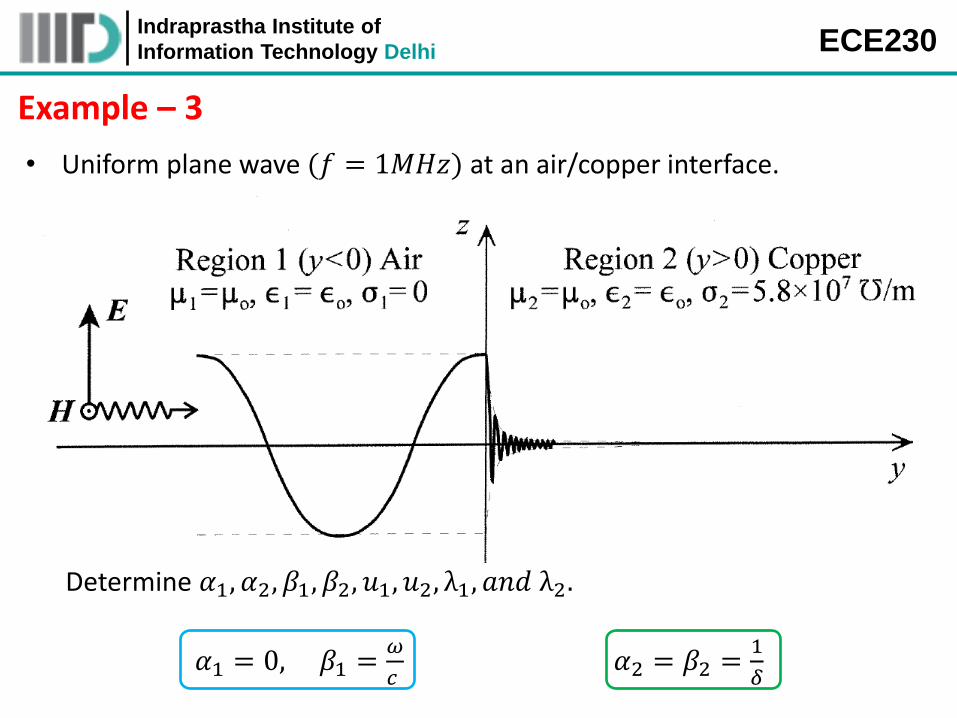
Example – 3
• Uniform plane wave (𝑓 = 1𝑀𝐻𝑧) at an air/copper interface.
𝛼1 = 0, 𝛽1 =𝜔
𝑐 𝛼2 = 𝛽2 =
1
𝛿
Determine 𝛼1, 𝛼2, 𝛽1, 𝛽2, 𝑢1, 𝑢2, λ1, 𝑎𝑛𝑑 λ2.
Indraprastha Institute of
Information Technology Delhi ECE230
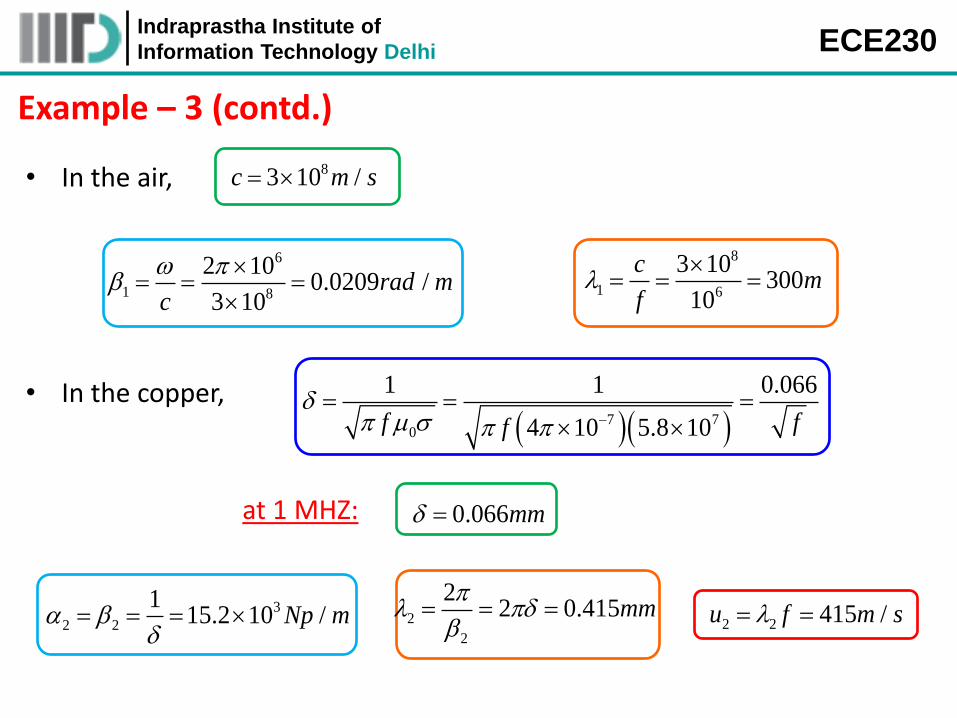
6
1 8
2 100.0209 /
3 10rad m
c
8
1 6
3 10300
10
cm
f
• In the air, 83 10 /c m s
• In the copper,
7 70
1 1 0.066
4 10 5.8 10f ff
at 1 MHZ: 0.066mm
3
2 2
115.2 10 /Np m
2
2
22 0.415mm
2 2 415 /u f m s
Example – 3 (contd.)

Indraprastha Institute of
Information Technology Delhi ECE230
Plane Waves in Good Conductors (contd.)
Electromagnetic Shielding
The previous example shows that we may enclose a volume with a thin layer of good conductor to act as an electromagnetic shield. Depending on the application, the electromagnetic shield may be necessary to prevent waves radiating out of the shielded volume or to prevent waves from penetrating into the shielded volume.
Indraprastha Institute of
Information Technology Delhi ECE230
Plane Waves in Good Conductors (contd.)
• Given a plane wave incident on a highly-conducting surface, the electric field (and thus the current density) is found to be concentrated at the surface of the conductor.
• The same phenomenon occurs for a current carrying conductor such as a wire.
• The effect is frequency dependent, just as it is in the incident plane wave example.
• This phenomenon is known as the 𝑠𝑘𝑖𝑛 𝑒𝑓𝑓𝑒𝑐𝑡. • Therefore, one can say, The process whereby the field intensity in a
conductor rapidly decreases is called 𝑠𝑘𝑖𝑛 𝑒𝑓𝑓𝑒𝑐𝑡. • 𝑠𝑘𝑖𝑛 𝑒𝑓𝑓𝑒𝑐𝑡 is the tendency of the charges to migrate from the bulk of
the conducting material to the surface, resulting in higher resistances (for ac!)
• The fields and associated currents are confined to a very thin layer (𝑡ℎ𝑒 𝑠𝑘𝑖𝑛) of the conductor surface.
Indraprastha Institute of
Information Technology Delhi ECE230
Plane Waves in Good Conductors (contd.)
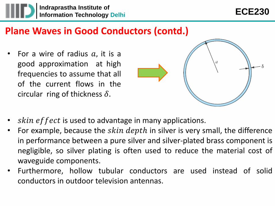
• For a wire of radius 𝑎, it is a good approximation at high frequencies to assume that all of the current flows in the circular ring of thickness 𝛿.
• 𝑠𝑘𝑖𝑛 𝑒𝑓𝑓𝑒𝑐𝑡 is used to advantage in many applications. • For example, because the 𝑠𝑘𝑖𝑛 𝑑𝑒𝑝𝑡ℎ in silver is very small, the difference
in performance between a pure silver and silver-plated brass component is negligible, so silver plating is often used to reduce the material cost of waveguide components.
• Furthermore, hollow tubular conductors are used instead of solid conductors in outdoor television antennas.
Indraprastha Institute of
Information Technology Delhi ECE230
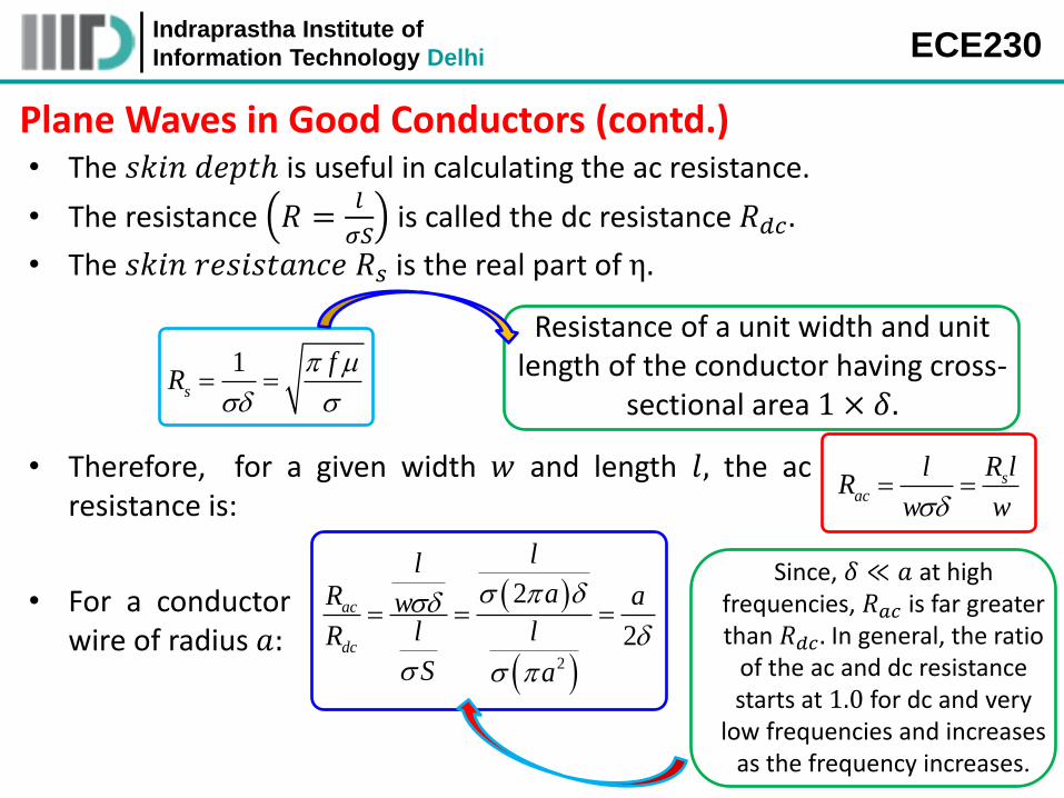
Plane Waves in Good Conductors (contd.) • The 𝑠𝑘𝑖𝑛 𝑑𝑒𝑝𝑡ℎ is useful in calculating the ac resistance.
• The resistance 𝑅 =𝑙
𝜎𝑆 is called the dc resistance 𝑅𝑑𝑐 .
• The 𝑠𝑘𝑖𝑛 𝑟𝑒𝑠𝑖𝑠𝑡𝑎𝑛𝑐𝑒 𝑅𝑠 is the real part of η.
1s
fR
Resistance of a unit width and unit length of the conductor having cross-
sectional area 1 × 𝛿.
• Therefore, for a given width 𝑤 and length 𝑙, the ac resistance is:
sac
l R lR
w w
• For a conductor wire of radius 𝑎:
2
2
2
ac
dc
llaR aw
l lR
S a
Since, 𝛿 ≪ 𝑎 at high frequencies, 𝑅𝑎𝑐 is far greater than 𝑅𝑑𝑐 . In general, the ratio
of the ac and dc resistance starts at 1.0 for dc and very
low frequencies and increases as the frequency increases.
Indraprastha Institute of
Information Technology Delhi ECE230
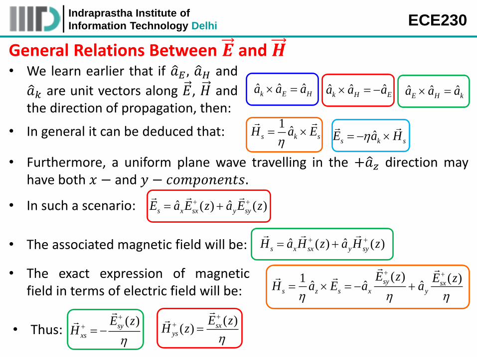
General Relations Between 𝑬 and 𝑯 • We learn earlier that if 𝑎 𝐸 , 𝑎 𝐻 and
𝑎 𝑘 are unit vectors along 𝐸, 𝐻 and the direction of propagation, then:
ˆ ˆ ˆk E Ha a a ˆ ˆ ˆ
k H Ea a a ˆ ˆ ˆE H ka a a
• In general it can be deduced that: 1ˆ
s k sH a E
ˆs k sE a H
• Furthermore, a uniform plane wave travelling in the +𝑎 𝑧 direction may have both 𝑥 − and 𝑦 − 𝑐𝑜𝑚𝑝𝑜𝑛𝑒𝑛𝑡𝑠.
• In such a scenario: ˆ ˆ( ) ( )s x sx y syE a E z a E z
• The associated magnetic field will be: ˆ ˆ( ) ( )s x sx y syH a H z a H z
• The exact expression of magnetic field in terms of electric field will be:
( )1 ( )ˆ ˆ ˆsy sx
s z s x y
E z E zH a E a a
• Thus: ( )sy
xs
E zH
( )
( ) sxys
E zH z
Indraprastha Institute of
Information Technology Delhi ECE230
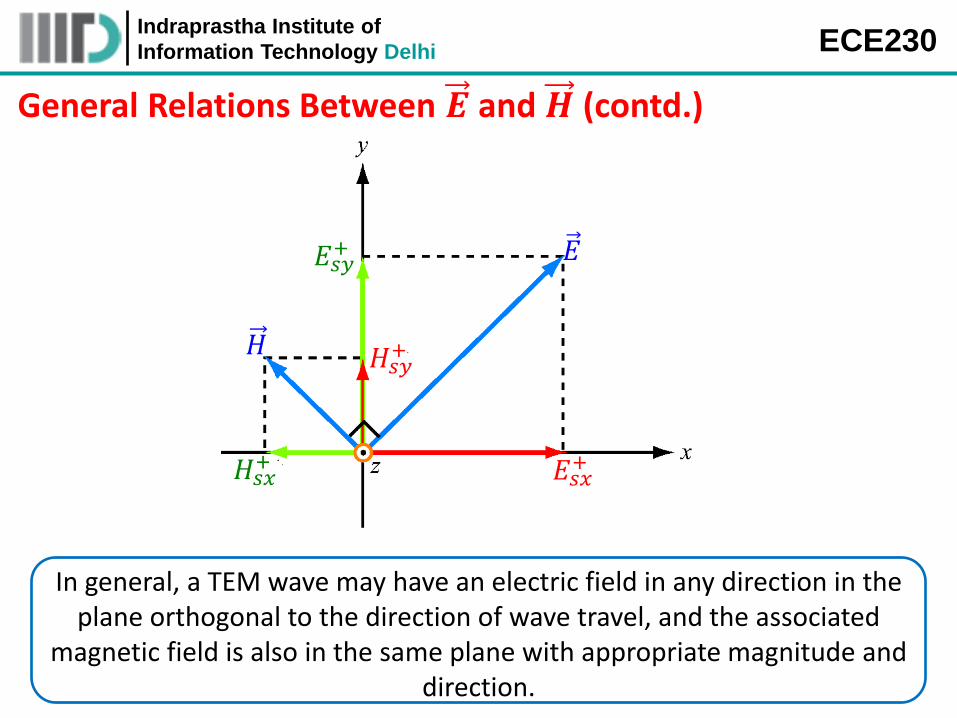
General Relations Between 𝑬 and 𝑯 (contd.)
𝐻𝑠𝑥+
𝐻𝑠𝑦+
𝐸𝑠𝑦+
𝐸𝑠𝑥+
𝐸
𝐻
In general, a TEM wave may have an electric field in any direction in the plane orthogonal to the direction of wave travel, and the associated
magnetic field is also in the same plane with appropriate magnitude and direction.