electromagnetics (engr 367) transmission lines (t-lines)
Post on 21-Dec-2015
232 views
TRANSCRIPT
Electromagnetics Electromagnetics (ENGR 367)(ENGR 367)
Transmission LinesTransmission Lines
(T-lines)(T-lines)
Introduction to T-linesIntroduction to T-lines• Function of T-line: to carry wave energy from Function of T-line: to carry wave energy from
one location to anotherone location to another• T-line terminologyT-line terminology
– origin of waves: origin of waves: sourcesource (e.g. generator) (e.g. generator)– destination of waves: destination of waves: loadload (e.g. receiving device) (e.g. receiving device)
• Value of transmitted electrical wave energyValue of transmitted electrical wave energy– provides light, heat or mechanical work, etc.provides light, heat or mechanical work, etc.– carries signal information carries signal information
• Audio: speech or musicAudio: speech or music• Visual images: static or dynamic, real-time or replayVisual images: static or dynamic, real-time or replay• Data: computer, telemetry system, financial activity, Data: computer, telemetry system, financial activity,
etc.etc.
Examples of T-linesExamples of T-lines
• Coax connection between the power Coax connection between the power amplifier amplifier and antenna of an RF broadcast and antenna of an RF broadcast systemsystem
• Fiber optic cable links between networked Fiber optic cable links between networked computerscomputers
• Power line connection between a generating Power line connection between a generating plant and a distant substationplant and a distant substation
• Connection between a cable TV service Connection between a cable TV service provider provider and a consumer’s setand a consumer’s set
• Trace connections between devices on a Trace connections between devices on a PCB PCB operating at HFoperating at HF
What can electrical engineers What can electrical engineers understandunderstand and and know how to know how to dodo with Wave Phenomena on with Wave Phenomena on
T-lines?T-lines?• Treat them as circuit elements with a complex Treat them as circuit elements with a complex
impedance that depends on length (impedance that depends on length (ll) ) andand frequency (frequency (=2=2f)f)
• Model wave propagation on them that behave Model wave propagation on them that behave as lossy, low loss, or approximately as lossy, low loss, or approximately
losslesslossless• Handle multiple line sections that connect to Handle multiple line sections that connect to
split power, match impedance, etc.split power, match impedance, etc.• Account for transient phenomena in T-lines Account for transient phenomena in T-lines
in in effect when they carry pulse/digital data effect when they carry pulse/digital data
Extraordinary Feature of T-Extraordinary Feature of T-lineslines• While the circuit model of a T-line While the circuit model of a T-line
includes parameters that depend on includes parameters that depend on length, T-lines have a unique length, T-lines have a unique characteristic impedance independent characteristic impedance independent of length! How can this be?of length! How can this be?
• We start with two assumptions that take We start with two assumptions that take us beyond traditional circuit analysis! us beyond traditional circuit analysis!
Two Assumptions:Two Assumptions:T-Line Theory vs. Circuit T-Line Theory vs. Circuit
Analysis Analysis • If connection distance (d) between devices isIf connection distance (d) between devices is
– on the order of a wavelength or more (d > ~on the order of a wavelength or more (d > ~), then ), then phase phase differences between devices may be appreciable differences between devices may be appreciable and and wave wave phenomena becomes significantphenomena becomes significant
– d << d << , then basic circuit analysis methods will suffice, then basic circuit analysis methods will suffice
• If the dimension (D) of a circuit element from its If the dimension (D) of a circuit element from its input input to output isto output is– large compared to a wavelength (D >> large compared to a wavelength (D >> ) then significant ) then significant
propagation time can exist through it and the propagation time can exist through it and the element should element should be treated as be treated as distributeddistributed (i.e., using (i.e., using R,L,C,G/unit length)R,L,C,G/unit length)
– D < D < , then a , then a lumpedlumped (ideal) element approximation is OK (ideal) element approximation is OK
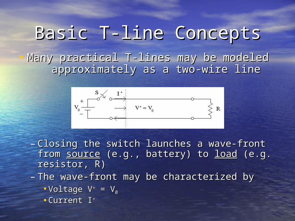
Basic T-line ConceptsBasic T-line Concepts• Many practical T-lines may be modeled Many practical T-lines may be modeled
approximately as a two-wire lineapproximately as a two-wire line
– Closing the switch launches a wave-front Closing the switch launches a wave-front from from sourcesource (e.g., battery) to (e.g., battery) to loadload (e.g. (e.g. resistor, R)resistor, R)
– The wave-front may be characterized byThe wave-front may be characterized by•Voltage VVoltage V++ = V = V00
•Current ICurrent I++
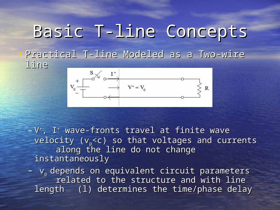
Basic T-line ConceptsBasic T-line Concepts• Practical T-line Modeled as a Two-wire linePractical T-line Modeled as a Two-wire line
– VV++, I, I++ wave-fronts travel at finite wave wave-fronts travel at finite wave velocity (vvelocity (vpp<c) so that voltages and currents <c) so that voltages and currents along the line do not change instantaneously along the line do not change instantaneously
– vvpp depends on equivalent circuit parameters depends on equivalent circuit parameters related to the structure and with line length related to the structure and with line length ((ll)) determines the time/phase delaydetermines the time/phase delay
Circuit Model versus Field Circuit Model versus Field ModelModel
for Wave Propagation on T-for Wave Propagation on T-lineslines• Circuit model: identifies equivalent Circuit model: identifies equivalent
circuit circuit parameters for T-line and treats parameters for T-line and treats it in it in terms of voltage (V) and current (I)terms of voltage (V) and current (I)
• Field model: applies Maxwell’s equations Field model: applies Maxwell’s equations to line configuration to get functions to line configuration to get functions for for EE, , HH followed by expressions for followed by expressions for power (P), wave velocity (vpower (P), wave velocity (vpp), etc. ), etc.
T-line Circuit versus Field T-line Circuit versus Field Model:Model:
ApplicabilityApplicability• Field model: a better approximation at Field model: a better approximation at
high frequency (HF) and more useful to high frequency (HF) and more useful to predict loss, complicated wave behaviorpredict loss, complicated wave behavior
• Circuit model: a better approximation at Circuit model: a better approximation at low frequency (LF) and simpler, so we low frequency (LF) and simpler, so we will focus on this model for nowwill focus on this model for now
T-line Theory: Circuit ModelT-line Theory: Circuit Model
• Static electric and magnetic field Static electric and magnetic field analysis analysis shows thatshows that– each real conducting wire each real conducting wire by itselfby itself has has
•per unit length resistance per unit length resistance RR [ [/m] (ohmic loss)/m] (ohmic loss)•per unit length inductance per unit length inductance LL [H/m] [H/m]
– two conducting wires two conducting wires separated from each separated from each otherother by a practical dielectric insulator by a practical dielectric insulator
havehave•per unit length conductance per unit length conductance GG [S/m] (leakage [S/m] (leakage
loss)loss)•per unit length capacitance per unit length capacitance CC [F/m] [F/m]
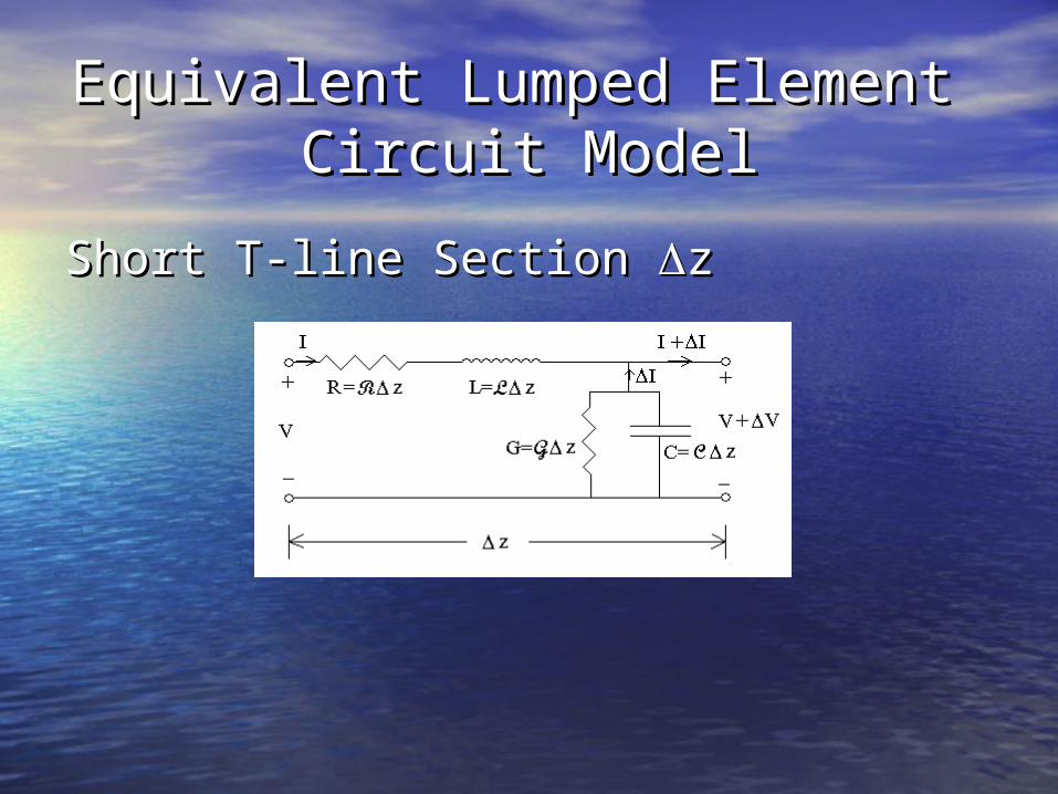
Equivalent Lumped Element Equivalent Lumped Element Circuit ModelCircuit Model
Short T-line Section Short T-line Section zz
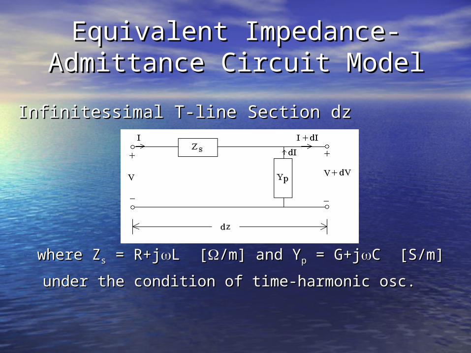
Equivalent Impedance-Equivalent Impedance-Admittance Circuit ModelAdmittance Circuit Model
Infinitessimal T-line Section dzInfinitessimal T-line Section dz
where Zwhere Zss = = R+R+jjLL [[/m] and Y/m] and Ypp = = G+G+jjC C [S/m][S/m]
under the condition of time-harmonic osc.under the condition of time-harmonic osc.
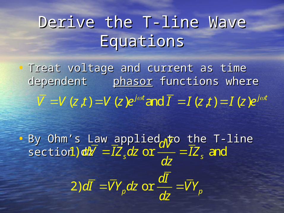
Derive the T-line Wave Derive the T-line Wave EquationsEquations
• Treat voltage and current as time Treat voltage and current as time dependent dependent phasorphasor functions where functions where
• By Ohm’s Law applied to the T-line By Ohm’s Law applied to the T-line section dzsection dz
( , ) ( ) and ( , ) ( )j t j tV V z t V z e I I z t I z e
1) or and
2) or
s s
p p
dVdV IZ dz IZ
dzdI
dI VY dz VYdz
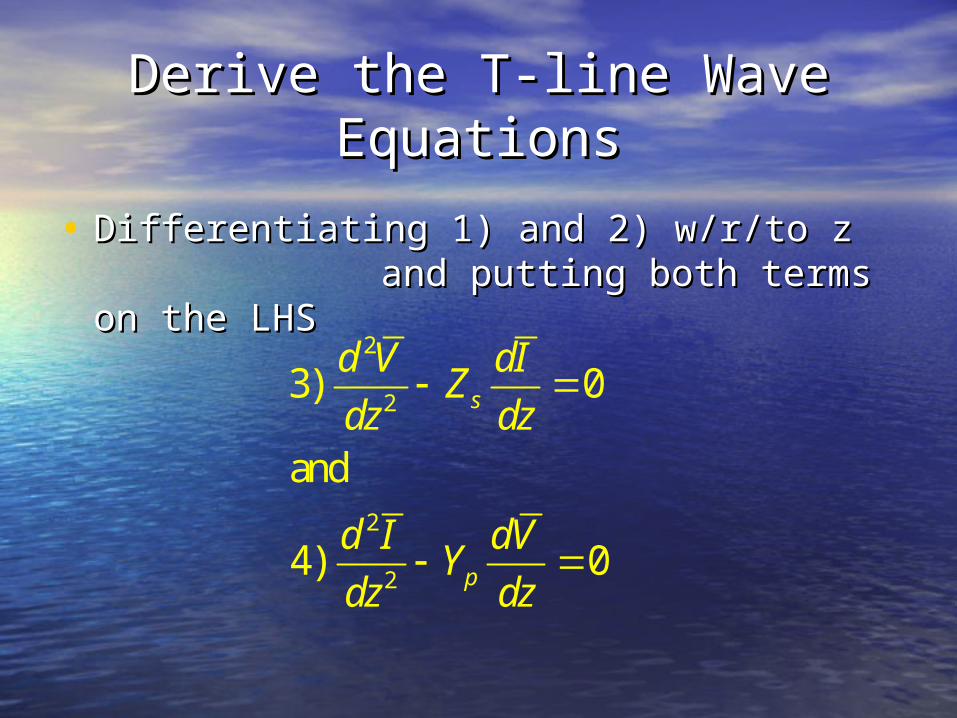
Derive the T-line Wave Derive the T-line Wave EquationsEquations
• Differentiating 1) and 2) w/r/to z Differentiating 1) and 2) w/r/to z and putting both terms on the LHSand putting both terms on the LHS
2
2
2
2
3) 0
and
4) 0
s
p
d V dIZ
dz dz
d I dVY
dz dz
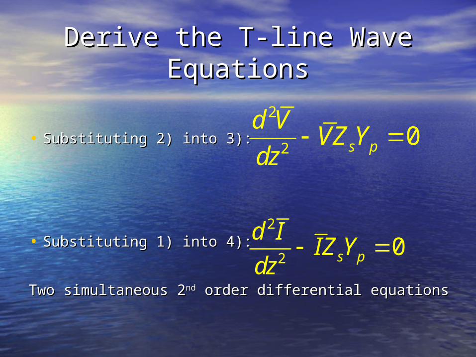
Derive the T-line Wave Derive the T-line Wave EquationsEquations
• Substituting 2) into 3):Substituting 2) into 3):
• Substituting 1) into 4):Substituting 1) into 4):
Two simultaneous 2Two simultaneous 2ndnd order differential equations order differential equations
2
20s p
d VVZ Y
dz
2
20s p
d IIZ Y
dz
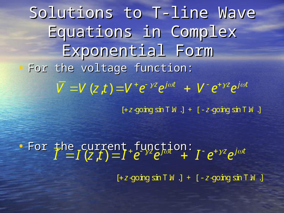
Solutions to T-line Wave Solutions to T-line Wave Equations in Complex Equations in Complex
Exponential Form Exponential Form • For the voltage function:For the voltage function:
• For the current function:For the current function:
[ -going sin T.W.] + [ - -going sin T.W.]
( , )
z j t z j t
z z
V V z t V e e V e e
[ -going sin T.W.] + [ - -going sin T.W.]
( , )
z j t z j t
z z
I I z t I e e I e e
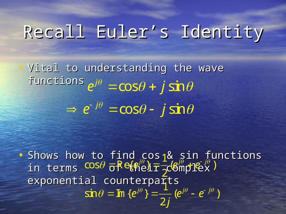
Recall Euler’s IdentityRecall Euler’s Identity
• Vital to understanding the wave functionsVital to understanding the wave functions
• Shows how to find cos & sin functions in Shows how to find cos & sin functions in terms terms of their complex exponential of their complex exponential counterpartscounterparts
cos sin
cos sin
j
j
e j
e j
1cos Re{ } ( )
21
sin Im{ } ( )2
j j j
j j j
e e e
e e ej
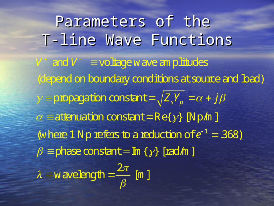
Parameters of the Parameters of the T-line Wave FunctionsT-line Wave Functions
1
and voltage wave amplitudes
(depend on boundary conditions at source and load)
propagation constant
attenuation constant Re{ } [Np/m]
(where 1 Np refers to a reduction of .368)
ph
s p
V V
Z Y j
e
ase constant Im{ } [rad/m]
2wavelength [m]
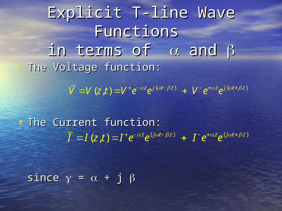
Explicit T-line Wave Functions Explicit T-line Wave Functions in terms of in terms of and and
• The Voltage function:The Voltage function:
• The Current function:The Current function:
since since = = + j + j
( ) ( )( , ) z j t z z j t zV V z t V e e V e e
( ) ( )( , ) z j t z z j t zI I z t I e e I e e

Other Essential T-line Other Essential T-line ParametersParameters
• Characteristic Impedance (ZCharacteristic Impedance (Z00))≡≡ratio of voltage ratio of voltage to current anywhere along the lineto current anywhere along the line
– from the circuit model with loss components, we from the circuit model with loss components, we havehave
– thus the general characteristic impedance isthus the general characteristic impedance is
Note: Note: ZZ00 is is independentindependent of length! of length!
1
( )where
( )
s s
s p p
s s s
dVI V
Z dz Z
Z Y Y j
Z Z Z j
G CR L
0
( )[ ]
( )sZV V j
ZI I j
R LG C
Other Essential T-line Other Essential T-line ParametersParameters
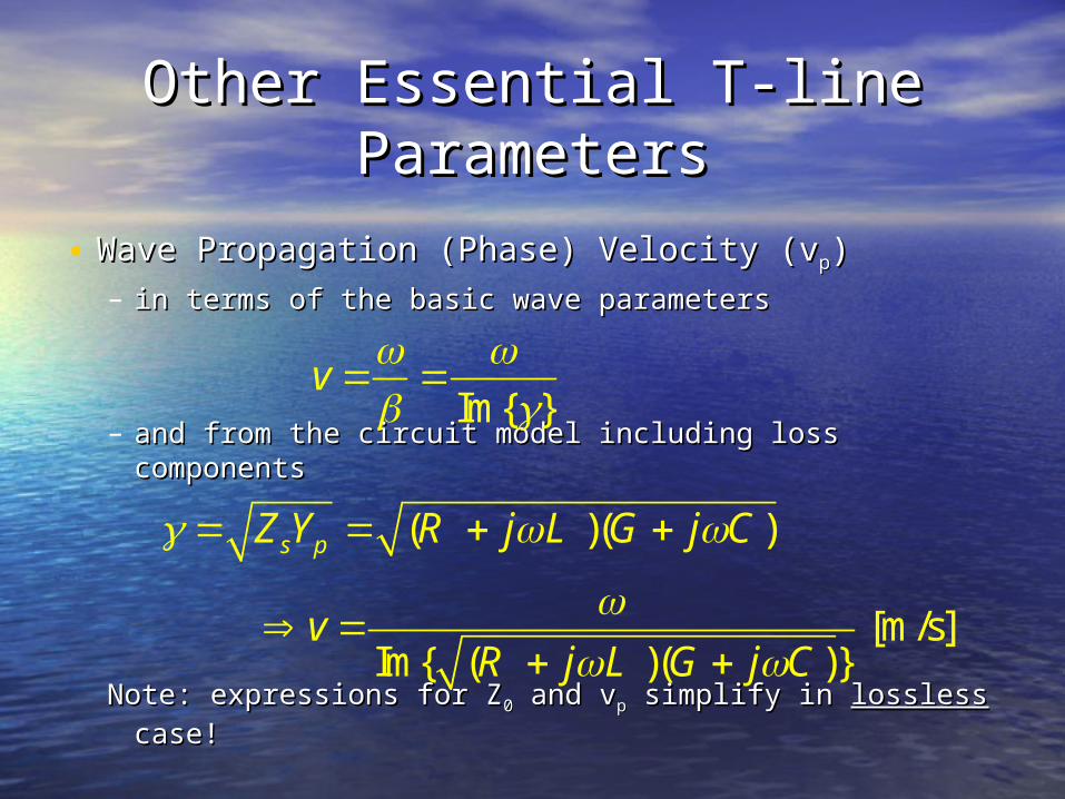
• Wave Propagation (Phase) Velocity (vWave Propagation (Phase) Velocity (vpp))– in terms of the basic wave parametersin terms of the basic wave parameters
– and from the circuit model including loss componentsand from the circuit model including loss components
Note: expressions for ZNote: expressions for Z00 and v and vpp simplify in simplify in losslesslossless case!case!
Im{ }v
( )( )
[m/s]Im{ ( )( )}
s pZ Y j j
vj j
R L G C
R L G C
Lossless T-lineLossless T-line
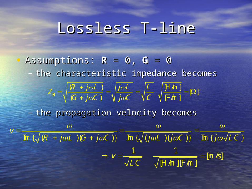
• Assumptions: Assumptions: RR = 0, = 0, GG = 0 = 0– the characteristic impedance becomesthe characteristic impedance becomes
– the propagation velocity becomesthe propagation velocity becomes
0
( ) [H/m][ ]
( ) [F/m]
j jZ
j j
R L L LG C C C
Im{ ( )( )} Im{ ( )( )} Im{ }
1 1[m/s]
[H/m][F/m]
vj j j j j
v
R L G C L C LC
LC
Low-loss T-line Low-loss T-line ApproximationApproximation
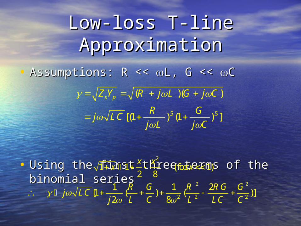
• Assumptions: Assumptions: RR << << LL, , GG << << CC
• Using the first three terms of the binomial Using the first three terms of the binomial seriesseries
.5 .5
( )( )
[(1 ) (1 ) ]
s pZ Y j j
jj j
R L G C
R GLC
L C
2
2 2
2 2 2
1 1 (for 1)2 8
1 1 2[1 ( ) ( )]
2 8
x xx x
jj
R G R RG G
LCL C L LC C

Low-loss T-line Low-loss T-line ApproximationApproximation
• Attenuation:Attenuation:
• Phase Constant:Phase Constant:
• Characteristic Impedance:Characteristic Impedance:
• Propagation Velocity: Propagation Velocity:
Note: expressions for Note: expressions for , , , Z, Z00, and v, and vpp in terms of in terms of , , RR, , LL, , GG and and CC left for you to work out as left for you to work out as HWHW! !
Re{ }
Im{ }
0 /sZ Z /v
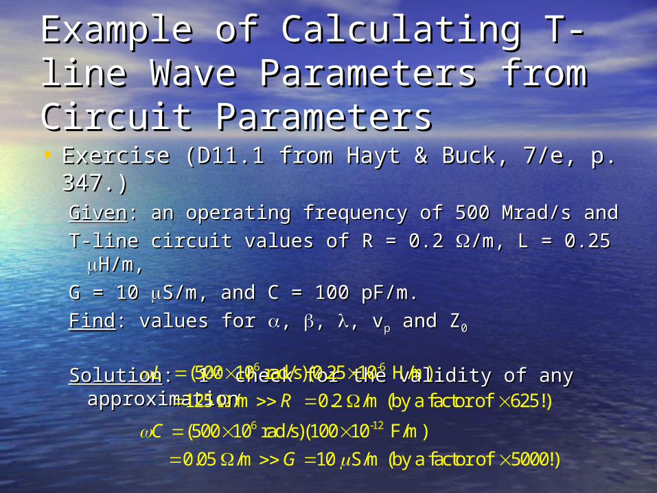
Example of Calculating T-line Example of Calculating T-line Wave Parameters from Circuit Wave Parameters from Circuit ParametersParameters• Exercise (D11.1 from Hayt & Buck, 7/e, p. Exercise (D11.1 from Hayt & Buck, 7/e, p.
347.)347.)GivenGiven: an operating frequency of 500 Mrad/s and : an operating frequency of 500 Mrad/s and
T-line circuit values of T-line circuit values of RR = 0.2 = 0.2 /m, /m, LL = 0.25 = 0.25 H/m, H/m,
GG = 10 = 10 S/m, and S/m, and CC = 100 pF/m. = 100 pF/m.
FindFind: values for : values for , , , , , v, vpp and Z and Z00
SolutionSolution: 1: 1stst check for the validity of any check for the validity of any approximationapproximation
6 -6
6 -12
(500 10 rad/s)(0.25 10 H/m)
125 /m 0.2 /m (by a factor of 625!)
(500 10 rad/s)(100 10 F/m)
0.05 /m 10 S/m (by a factor of 5000!)
L
R
C
G
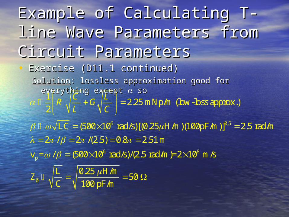
Example of Calculating T-line Example of Calculating T-line Wave Parameters from Circuit Wave Parameters from Circuit ParametersParameters• Exercise (D11.1 continued)Exercise (D11.1 continued)
SolutionSolution: lossless approximation good for everything : lossless approximation good for everything except except so so
6 0.5
6 8p
0
12.25 mNp/m (low-loss approx.)
2
(500 10 rad/s)[(0.25 H/m)(100pF/m)] 2.5 rad/m
2 / 2 /(2.5) 0.8 2.51 m
v = / (500 10 rad/s)/(2.5 rad/m)=2 10 m/s
0.25 H/mZ 5
100 pF/m
C LR G
L C
LC
LC
0
SummarySummary
• T-lines carry wave energy over T-lines carry wave energy over distances valuable in RF broadcast, distances valuable in RF broadcast, computer, cable TV, power and other computer, cable TV, power and other HF applicationsHF applications
• If the transmission distance and If the transmission distance and element dimensions are significant element dimensions are significant compared to a wavelength, then T-compared to a wavelength, then T-lines exhibit wave phenomena and lines exhibit wave phenomena and distributed element behaviordistributed element behavior
SummarySummary
• Many practical T-lines act like a two-wire Many practical T-lines act like a two-wire line with voltage and current wave-fronts line with voltage and current wave-fronts that propagate at finite speedthat propagate at finite speed
• The circuit model of a T-line, applicable at The circuit model of a T-line, applicable at lower frequencies, includes per unit length lower frequencies, includes per unit length resistance (resistance (RR)), inductance (, inductance (LL), capacitance ), capacitance ((CC) and conductance () and conductance (GG) that lead to wave ) that lead to wave equations for voltage and current equations for voltage and current
SummarySummary
• T-line wave equations are satisfied by T-line wave equations are satisfied by complex exponential functions for voltage complex exponential functions for voltage and current representing forward and and current representing forward and backward sinusoidal traveling wavesbackward sinusoidal traveling waves
• Lossy, low-loss or lossless T-lines may be Lossy, low-loss or lossless T-lines may be described by parameters including phase described by parameters including phase constant (constant (), attenuation (), attenuation (), wavelength ), wavelength ((), propagation velocity (v), propagation velocity (vpp) and ) and characteristic impedancecharacteristic impedance (Z(Z00))
ReferencesReferences• Hayt & Buck, Hayt & Buck, Engineering Engineering
ElectromagneticsElectromagnetics, 7/e, McGraw Hill: , 7/e, McGraw Hill: New York, 2006.New York, 2006.
• Kraus & Fleisch, Kraus & Fleisch, Electromagnetics Electromagnetics with Applicationswith Applications, 5/e, McGraw Hill: , 5/e, McGraw Hill: New York, 1999.New York, 1999.