electron beam welded tooling - spe automotive · electron beam welded tooling david stewart, ......
TRANSCRIPT

Page 1
ELECTRON BEAM WELDED TOOLING
David Stewart, Dr. Xia-Yang Sheng Stewart Automotive Research, LLC
Abstract
Rapid tooling processes have traditionally been limited in application to relatively small components. The Zoned Tooling (Z-Tool) process differs from other technologies in that it utilizes forged plate stock as its raw material and can be used to manufacture even the largest of automotive molds. Utilizing knowledge based programming features within a CAD environment, a tool is sectioned into a number of segments (zones) that are then rough cut with a waterjet or milling machine and electron beam welded into the final form. Traditional roughing and gun-drilling are eliminated, and finish machining and subsequent processes proceed in the normal manner. The challenges and advantages of the process are discussed, along with a demonstration of a typical application.
Introduction The benefits offered by various advanced moldmaking techniques typically fall into two categories: speed and performance. Where compressed development times are critical, high-speed machining and rapid tooling processes can offer substantial lead-time savings. Where the performance of traditional tools is problematic, techniques such as freeform fabrication and vapor deposition can offer improved material properties and features such as conformal cooling that provide savings in the operation of the tool. The cost of employing such technologies is typically higher than traditional methods, but can often be financially justified when the cost savings over the life of the tool are considered. Even so, until these economic advantages become commonly accepted at the purchasing level, the higher piece prices for such tools is an impediment to their acceptance in the marketplace.
This issue is even more problematic when considering larger tools. Many of the advanced tooling techniques have build rates or variable costs that limit their competitiveness as tool dimensions increase. A fabrication process that deposits at a rate of cubic inches per hour, or with materials costs over a dollar a pound will obviously suffer a large cost penalty when used to construct a 50,000 pound instrument panel mold. Because of the recent financial hardships faced
by the suppliers of large tools in North America, most of the recent research activity in advanced tooling has continued to focus on smaller tools, where the capital and experimental budgets are more manageable and the economics of commercialization more straightforward. Projects such as Ford’s thermal spray technology [1] and Weber Manufacturing’s Nickel Tooling Technology are the exception, and offer improvements in some large-tool niches.
Technical successes such as these indicate the potential for a more sophisticated approach to large-tool manufacture, but the appropriate combination of speed, performance, and cost remains a challenge. Previous research efforts have been driven by technology, with many processes now in commercial use having been originally developed in the university or government lab environment. Stewart Automotive Research and its development partners decided to tackle this problem by working backwards, starting with the tool shop and the economics, and then moving to a description of the technology.
Zoned Tooling The tooling companies made several strong points that drove the requirements for the process description.
• Tool Cost. The current purchasing climate of givebacks and price reductions will not support much, if any increase in the cost of the tool, and cost reductions are greatly desired to compete on price with China and other low-wage markets.
• Existing Capital Investments. Tool shops have a large existing investment and associated debt that must be serviced. A new process would preferably not invalidate an existing investment, but rather make it more productive.
• Performance. Improved thermal and mechanical performance is desired to provide differentiation from low-cost commodity suppliers.
A technical cost modeling technique that allowed evaluation of the financial impact of various manufacturing strategies on each component of the value chain was also used to iteratively screen our ideas [2], finally resulting in the patent pending Zoned Tooling (Z-Tool) concept.

Page 2
The key idea is to split a large tool up into smaller segments, or zones, which can be manufactured from inexpensive plate stock on smaller, more productive milling machines and then assembled into a complete tool. Complex internal geometry can be added to the individual blocks, and high performance materials can be selectively used where needed. Many variants of this concept have been employed in the past, but the final joining process has never proven satisfactory. Vacuum brazing is expensive, can result in unwanted tempering of the steel, and leaves a visible joint line. Mechanical fastening has proven itself in large inserts, but is cumbersome as the number of sections increases, and also leaves a witness mark. The primary enabler for the Z-Tool technology lies in the use of electron beam welding for joining, which allows deep penetration welds to be made with no special joint preparation or filler metal. Because the welds are performed in vacuum, the result is a weld area with the same chemistry as the base metal.
As illustrated in Figure 1, the Z-Tool process intersects itself into the normal tool build schedule by replacing the normal steps of cooling line design, ordering of a large forged block, roughing, gun-drilling, and heat treat with a new process, made up of the following steps:
• Tool Design. Solid modeling tools allow a surface model of a tool designed in the traditional manner to be sectioned into zones. Heat transfer simulation and path optimization tools are used to design cooling line geometry.
• Plate roughing. The individual sections are cut from plate or bar stock. Because the thickness dimension of the stock is less than 10 inches, the steel is easier to quench, eliminating problems with hardness variation and porosity that can occur in the center of very large blocks. Strategic placement of the zone boundaries can result in large material savings. The smaller block size and better access to the contours allows efficient roughing by waterjet and high-speed milling where most of the rough material can be removed in large pieces, rather than being turned into chips. Residual stock of between .040” and .250” is left for finish machining.
• Fixturing. The zone sections are demagnetized, fixtured together and placed in the vacuum chamber.
• Welding. The zones are EB welded together. Penetration depth of up to 10 inches is possible, at speeds from 10-50 inches per minute. The entire welding operation takes only a few hours.
• Heat treating. The tool is then heat treated to relieve welding stresses and to normalize the grain structure.
• Shipping. The roughed tool preform is then sent to the mold shop for finishing and final build. Because the plate sections can be stocked and a small fraction of the machining time is required, the entire process can shave weeks or months off the traditional methods.
Replacing low-value added, commodity machining and logistical tasks with a less expensive, higher-value added Z-Tool process can free up mold shop equipment and staff resources for more profitable activities, while at the same time delivering increased performance and reduced lead times for the customer.
Electron Beam Welding Electron beam (EB) welding is a high energy density fusion process that transfers energy to a joint using an intense beam of electrons. It was initially applied to industrial processes in the 1950’s, and has since matured into an important modern joining technology able to produce welds with quality and depth superior to other welding processes. EB welding is most commonly found in the aerospace industry, where it is used for anything from welding structural components for fighter aircraft (F-15 through F-22) to the repair of turbine blades and seals. The process uses an electron beam gun in a vacuum chamber to focus a stream of electrons onto a grounded work piece. Unlike laser welding, where the beam can be reflected, the coupling efficiency of the electron beam is near 100%. The beam is focused and deflected with magnetic optics. Figure 2 shows the arrangement of the components in the gun along with the 60 kilovolt, 42 kilowatt Sciaky gun used by SAR for testing.
Because a highly focused electron beam can concentrate enormous power on a small spot on a workpiece, there is extremely rapid local melting and vaporization at the joint to be welded. The welds produced can be very deep, narrow, and almost parallel-sided (Figure 3). They have relatively small heat-affected zones, and can usually be produced with a single welding pass. Typically, no filler metal is used, and the joint is simply fixtured in place and welded. The top and bottom bead shown in the figure is a result of thermal expansion, not filler. More aspects of the electron beam welding process can be placed under precise computer numerical control than is possible with other welding processes. In addition to readily joining common metals, the process can also join dissimilar (copper to aluminum) or hard-to-weld materials (tungsten) [3].
When deep penetration is required, the focused electron beam can strike the workpiece in a spot as small as 0.25 mm. The resulting temperature of about

Page 3
14,000C forms a deep vapor hole. The material at the leading edge of the vapor column melts, with the liquid suspended by vapor pressure. The beam is electronically oscillated to keep the column open. As the workpiece is moved beneath the beam, a weld is formed when the molten material flows around the hole and solidifies after filling the trailing edge. This is referred to as keyhole welding (Figure 4) because of the distinctive shape of the hole and the trailing weld.
Sciaky VX-300 Sciaky, Inc. of Chicago, Illinois was an early pioneer in electron beam welding, and is partnering with SAR in developing the Z-Tool process. Their development lab includes a model VX-300 moving gun electron beam welder with a 300”x108”x132” vacuum chamber capable of handling even the largest of automotive molds (Figure 5). Using this equipment, we were able to perform welding tests at the coupon and complete tool assembly levels.
EB Welding of Tool Steels The use of any welding process to assemble the complete tool is a major departure from conventional moldmaking wisdom. Welds are usually only involved in the tooling process as a repair for some error, such as a tool crash or a cracked mold. In these cases, the repair is made under difficult conditions, because often the entire tool cannot be brought to the appropriate temperature for welding and post-weld stress relief. The resulting welds exhibit a substantial hardness variation from the base metal, and when textured or polished, they tend to be very obvious on the tool surface and in the finished parts.
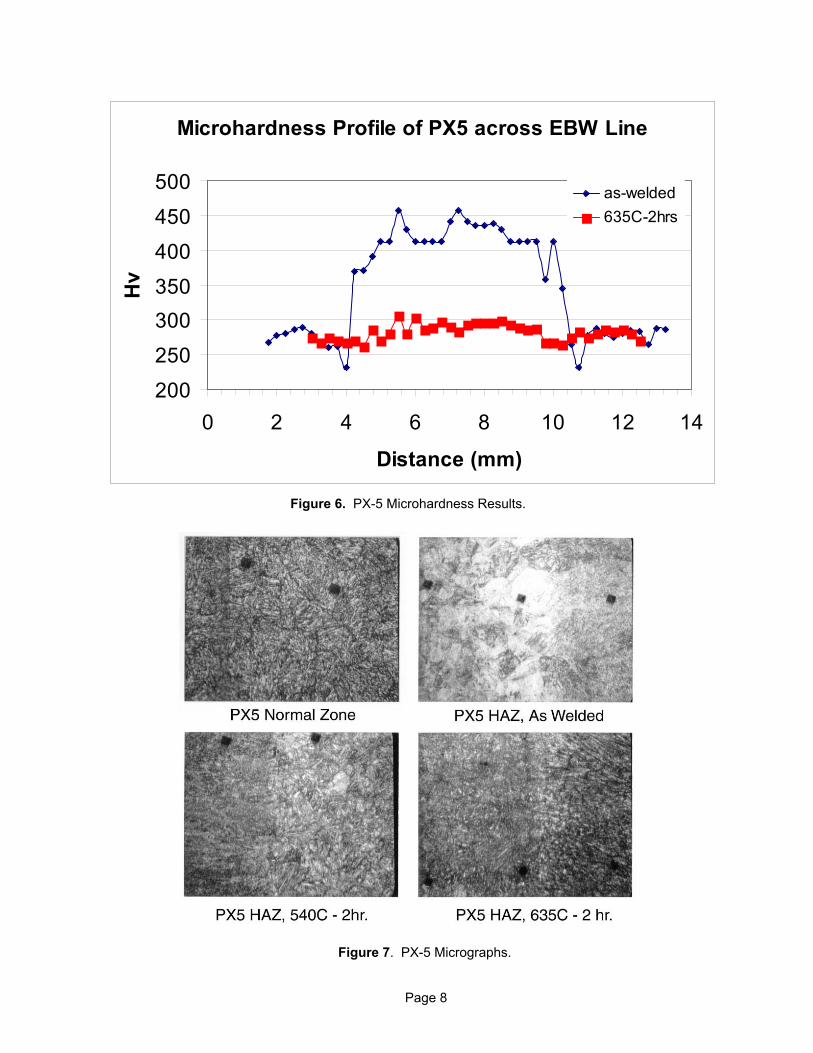
Electron beam welding, on the other hand, provides more efficient energy input than TIG welding. Due to the inherently narrow welds and heat-affected zones, and the rapid heating, melting, solidification, and cooling times, base metal properties can be retained close to the weld. It is also possible to reduce or eliminate property variations by post-weld heat-treating the welded sections. Figure 6 shows the hardness profile across a deep penetration EB weld for International Mold Steel’s PX-5 tool steel before and after heat treatment. The fast cooling rates quench the fusion zone to a high hardness, while the heat affected zone softens slightly by over-tempering. Figure 7 shows the grain structure at the HAZ/fusion transition for the same sample. After final heat treatment at the original tempering temperature, a fine grain structure is regained, and the steel across the weld polishes identically to the base metal. PX-5 has a chemistry designed to minimize problems with
texturing after welding, and tests performed by Melco Engraving Inc. of Rochester Hills Michigan show no visible defects across the weld for a wide variety of textures (Figure 8). It should also be noted that the heat treatment step does not represent an additional expense, as a large block requires a stress relief after roughing if close tolerances are to be kept during finishing and over the life of the tool.
SAR and A. Finkl and Sons of Chicago, Illinois, the largest manufacturer of forged P-20 mold steel blocks in North America, have tested a number of other alloys for the process, including P-20, which is particularly difficult to weld without cracking. Figure 9 shows the hardness profile for Finkl Mold Die P-20 after welding and heat treatment. As welded, the material quenches to a very high hardness, as is typical for a steel with this carbon content. This poses a problem, however, as the hard and brittle material in the fusion zone is prone to cracking from thermal stress on cool-down. The shape of the EB weld is helpful with this problem. Instead of the semicircular melt pool of traditional TIG welding, the narrow and parallel EB weld relieves stress with a small amount of transverse shrinkage, as opposed to the warpage and high residual stresses that result from the shrinkage of a normal melt pool. Consequently, we were able to weld P-20 successfully with no pre-heating, but the process window is narrow. A small amount of pre-heating in the blocks allows P-20 to be welded without cracking over a wide range of weld settings. After a post weld heat treat to temper the hardened material, the hardness variation across the weld is minimal, and the weld cannot be located visually on a polished specimen.
Given our results with P-20, Finkl was able to specify a minor change in the chemistry to improve the EB weldability of the steel. Their FXLC-130 alloy has approximately the same cost and properties as P-20, but also includes some of the same alloying elements that give PX-5 its weldability, but with a lower sulfur content. Figure 10 shows that the hardness for this alloy does not rise quite as high as P-20 (but higher than PX-5), but more importantly, the alloy exhibited no cracking when welded without preheating, providing an inexpensive P-20 equivalent more suited to EB welding.
Because the Z-Tool process allows for the possibility of using different materials in different areas of a tool, there is a desire to take advantage of this by using an inexpensive steel such as FXLC, P-20, or their non-and another steel with more desirable properties at the parting lines and polished surface. Welding tests were therefore also conducted with Finkl Mar-X, an age hardening 15-5 stainless tooling alloy, and Finkl

Page 4
Press-Die, an age hardening hot-work alloy. Both steels polish well, and are easily welded by EB or TIG. After heat treatment (Figures 11 and 12) the materials deliver extremely consistent hardness and grain structure as a result of the age hardening process. Even TIG welds can be heat treated and blended perfectly into the tool surface, allowing a tool to be reconfigured by welding. For example, a prototype tool could be fashioned with a Mar-X cavity surface and P-20 sides, allowing any engineering changes to be welded into the tool before final finishing and tool build, thus eliminating a redundant tool.
Z-Tool Software Z-Tool opens up the design space so much that it can be difficult to manage the tool design process without help. The other critical piece of technology that enables the cost-effective implementation of the Z-Tool strategy is solid modeling software. As the number of segments increases, the use of traditional drawings and surface models becomes more difficult. Using the EDS Unigraphics CAD/CAM environment, SAR has developed Z-Tool specific software tools to automate the sectioning of the blocks and the generation of G-code for rough machining.
Solid Modeling To illustrate the advantages of segmented tool construction and the challenges posed by the larger number of work pieces, we will consider a simple implementation for a large tool. The bumper fascia model shown in Figure 13 is provided by the customer and imported from a neutral CAD format into UG. Flaws in the surfaces are healed and a solid model (Figure 14) is created. Loose tolerances can be specified for the repair operations, because the model will only be used for heat transfer analysis and to generate a roughed preform. The model is then sectioned into zones with thicknesses consistent with a database of available plate inventory (Figures 15 and 16). Where fine polishes are necessary, the system will match the blocks intersecting part surfaces to plate produced from the same heat at the steel mill, insuring consistent chemistry, grain structure, and hardness. For tools with a deep contour such as the one shown here, the amount of material saved when laying out the blocks can be tens of thousands of pounds relative to the single block used traditionally, and will provide savings even over a simple U-shaped forging (which has a very long lead time). Where the primary contours of the cavity are in both planes, additional transverse cutting planes can be added and the tool built up out of bar stock rather than plate.
Cooling Lines The tool model is then exported for analysis, where software developed in partnership with Altair Engineering of Troy, Michigan is used to perform a path optimization for the cooling lines [4]. Constraints relating to the machining process insure that the optimized lines are manufacturable. Figure 17 shows the line locations for the fascia tool. The line geometry is created with solid modeling tools customized for that purpose to insure that appropriate manufacturing data (drill size, cutting tool diameter) is passed on to the postprocessor when the CAM functions are performed. The lines are fused watertight during EB welding, where the beam simply jumps across the empty space (it just sees the line as more vacuum) and welds both sides. Because the cooling rates are so fast, minimal flash or backbeading occurs at the joint. In addition to the connect-the-dots strategy shown here, any arbitrary path can be machined into the faces of the block (the manifold feeding the cooling lines in Figure 17 was created this way), and traditional cooling circuits can be milled and drilled into the individual zones as necessary. Because the size of the blocks is small relative to the overall tool size, the use of expensive gun-drilling machines is reduced or eliminated.
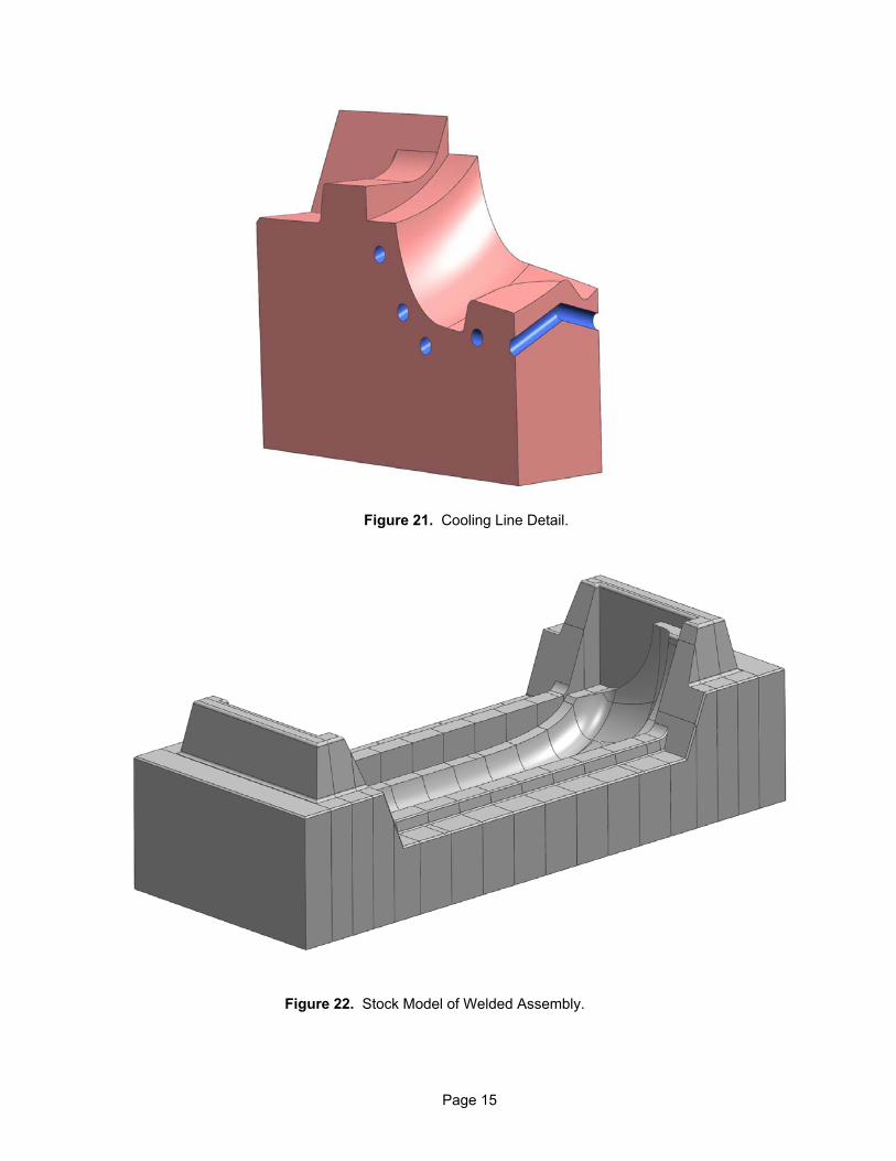
Toolpath Generation The solid model is then used by the UG CAM module to generate roughing code for the individual machining operations. Figure 18 shows one of the zones and the stock model from Figure 16 from which it will be machined. There are several advantages to performing rouging on the individual zones instead of a monolithic block. With the zone plates representing a slice from within the cavity, we now have access to all sides of the workpiece, and can use a waterjet or milling machine to part away the bulk of the material that must be removed (Figure 19). The increased access also means that programming is greatly simplified, because the surfaces of even the deepest cavities are no farther from the spindle than the thickness of the plate. Off of the tool surface, the machining involves only planar 2D operations. The amount a material that must be removed from the contour by conventional machining in the Z-Tool process is just that between the rough surface and the waterjet surface and is illustrated as a green solid in Figure 20. The mold shop will finish the remaining material (the space between the solid and the final part surface controur in Figure 20). The cooling lines can be made by angle drilling (which is much easier with a small workpiece) or milling, and typically can be done on the same machine that performs the roughing. Figure 21 illustrates the type

Page 5
of cooling geometry that can be created with simple milling and drilling operations.
A residual stock model of the entire welded assembly that accounts for the shrinkage at the welds can be provided as a starting point for the generation of high speed machining toolpaths, eliminating the need for air passes to establish a known surface (Figure 22). If desired, the welded assembly can be scanned in a CMM and squared before shipping. Reference surfaces can also be added to allow rapid and accurate location of the part at the mold shop, minimizing the amount finishing stock that must be left during roughing.
Because of the easy access to the workpiece and the loose tolerances on the contoured surfaces, virtually all of the G-code for controlling the machining process can be automatically generated by the CAM software, which offsets the increase in fixturing operations that comes with the higher piece count. Fixturing of the individual blocks is also easier because of their standardized shape and small size. Because the price for a given spindle horsepower for milling machines scales exponentially with increasing axis travel, and Z-Tool roughing is an inherently parallel operation that removes a much smaller volume of material by machining, a small cell of horizontal mills and a waterjet cutter can perform roughing tasks equivalent to an entire shop of large vertical, bridge, and boring mills at a fraction of the cost.
Process Economics Chart 1 gives details for the relative costs of Z-Tool construction vs. a traditional tool build for an instrument panel cover tool. The primary savings are in roughing time and programming and cooling line design, and far outweigh the cost of the welding process. This analysis assumes that the roughing is performed at a traditional tool shop and that no materials cost savings are realized through nesting (the cavity is not deep and curves in two planes). Further savings can be realized by using small high-speed mills for roughing instead of the more traditional “heavy iron.” The mold shop incurs some
small additional costs for design time to coordinate the cooling line placement and some planar machining operations to square the Z-Tool blank.
Conclusions Electron beam welding has proven itself as a robust technology for joining tool steels, enabling a new method of large tool construction that delivers features such as conformal cooling and allows the use of high-performance steels, while providing overall cost savings in tool construction. Thermal optimization and solid modeling software tools allow the process to be implemented cost effectively, in spite of the greater complexity in design.
Acknowledgements This research was funded in part by a grant from the NIST’s Advanced Technology Program, which was managed by Felix Wu. Thanks also to Siddharth Bammi of MIT’s Materials Systems Laboratory for technical cost modeling and development partners Altair Engineering for their simulation software expertise, A. Finkl and Sons for supplying steel and metallurgical services, EDS for assistance with Unigraphics development, and Sciaky for sharing their expertise in electron beam welding.
References 1. R. Chalmers, “Rapid Tooling Technology from Ford Country.” SME’s Manufacturing Engineering, Vol. 127, No. 5
2. R. Kirchain, F. Field, “Process Base Cost Modeling: Understanding the Economics of Technical Decisions.” Encyclopedia of Materials Science and Engineering, Elsevier Science Publications.
3. “Procedure Development and Practice Considerations for Electron Beam Welding.” 1993 ASM Handbook, Vol. 6: Welding, Brazing, and Soldering.
4. R. Mayavaram, M. Reddy, J. Tolle, and D. Stewart, “Design and Optimization of Conformal Mold Cooling Passages.” ACCE 2003.

Page 6
Figure 1. Z-Tool Process Diagram.
Figure 2. Electron Beam Gun Optics and Sciaky 60 kV/42 kW EB Gun

Page 7
Figure 4. EB Keyhole Welding.
Figure 5. Sciaky’s 25 Foot Long VX-300 Moving Gun EB Welder.
Figure 3. Typical EB Weld Profile.
Page 8
Microhardness Profile of PX5 across EBW Line
200
250
300350
400
450
500
0 2 4 6 8 10 12 14
Distance (mm)
Hv
as-welded635C-2hrs
Figure 6. PX-5 Microhardness Results.
Figure 7. PX-5 Micrographs.

Page 9
Figure 8. PX-5 Textured Plaque Tool and Injection Molded Polypropylene Sample.
Microhardness Profile of P20 across EBW Line
200
300
400
500
600
700
0 2 4 6 8 10Distance (mm)
Hv
as-welded1120F-2hrs
Figure 9. Finkl Mold Die (P-20) Microhardness Results.

Page 10
200
250
300
350
400
450
500
550
600
0 2 4 6 8 10 12 14 16 18 20 22 24 26 28 30
Distance (mm)
Hv
as-welded1000F2hrs1175F2hrs
Microhardness Profile of FXLC-130 Across EBW Line
Figure 10. Finkl FXLC-130 Microhardness Results.
250
300
350
400
450
500
0 20 40 60Distance (mm)
Hv
#3 as-welded#3 solution#3 900F-1hr
Microhardness Profile of MAR-X Across EBW Line
Figure 11. Finkl MAR-X Microhardness Results.

Page 11
350
400
450
500
550
600
0 10 20 30Distance, mm
Hv
As-welded1100F-4hrs
Microhardness Profile of Press-Die Across EBW Line
Figure 12. Finkl Press-Die Microhardness Results.
Figure 13. Bumper Fascia Surface Model.

Page 12
Figure 14. Simplified Solid Model Geometry.
Figure 15. Solid Model Sectioned into Zones.
Figure 16. Plate Stock for Individual Zones.

Page 13
Figure 17. Conformal Cooling Line Geometry.
Figure 18. Individual Zone Block Inside Plate Stock Model.

Page 14
Figure 19. Rough Stock Removed by Waterjet.
Figure 20. Rough Stock Removed by Machining.
Page 15
Figure 21. Cooling Line Detail.
Figure 22. Stock Model of Welded Assembly.

Page 16
Tool: IP CoverPart Size 55X25X18Tool Size 70X42X42Weight 35438.76
Traditional Build Z-ToolHours Rate Price Hours Rate Price
Design 450 65 $29,250.00 420 65 $27,300.00Surfacing 100 65 $6,500.00 120 65 $7,800.00CNC Roughing 300 85 $25,500.00 85 $0.00CNC Finishing 400 115 $46,000.00 430 115 $49,450.00Boring (squaring) 335 70 $23,450.00 335 70 $23,450.00 (roughing) 300 70 $21,000.00EJ Box & Plates $0.00 $0.00EDM 250 70 $17,500.00 250 70 $17,500.00Benching 325 58 $18,850.00 325 58 $18,850.00Assembly 670 55 $36,850.00 670 55 $36,850.00CMM 60 70 $4,200.00 70 70 $4,900.00Plumbing $0.00 $0.00Wiring $0.00 $0.00Spotting 100 55 $5,500.00 100 55 $5,500.00Gun Drilling 200 70 $14,000.00 20 70 $1,400.00Heat Treat $4,000.00 $5,000.00Z-Tool Roughing 70 140 70 $9,800.00E-Beam 400 Subtotal 12 400 $4,800.00 SubtotalShipping $3,000.00 $255,600.00 $4,500.00 $217,100.00Texturing $18,000.00 $18,000.00 SavingsPlating $0.00 $38,500.00Flow Analysis $0.00 15.06%Tryouts $0.00Mold Blocks $63,789.77 $63,789.77Plate Stock $15,000.00 $15,000.00Hot Runner $0.00Other Materials $0.00 Savings
TOTAL $352,389.77 TOTAL $313,889.77 $38,500.0010.93%
Roughing+Gun Drilling+Material = $124,289.77 Z-Tool Blank = $83,939.77Related design expenses = $3,900.00 Design = $3,900.00Heat treat = $4,000.00 Heat treat = $5,000.00 Savings
$132,189.77 $92,839.77 $39,350.0030%
Chart 1. Task Breakdown and Costs for IP Cover Tool