electronic circuit breaker ess1 for system...
TRANSCRIPT

www.e-t-a.com
Electronic Circuit Breaker ESS1 for System SVS1
Issue B 5 - 7
5
Description
ESS1-.../SVS1-...
The electronic circuit breaker ESS1 is designed to ensure selectivedisconnection of individual loads in industrial systems which arepowered by a DC 24 V switch mode power supply.Selectivity means that the ESS1 responds faster to overload or shortcircuit conditions than the power supply.
The ESS1 has four major tasks:
1. In the event of an overload or short circuit in a load circuit,even the shortest break-down of the output voltage of thepower supply to values below 18 V must be prevented under allcircumstances.Otherwise all other components fed by the power supply willrespond unpredictably to the voltage dip. Result: reset, re-start,standstill of components or whole system. The voltage dip iscaused by the characteristic overcurrent behaviour of the powersupply (straight characteristic curve, fold-back curve, hiccup modeetc.).
2. Selective protection/disconnection must be ensured even atworst-case overload conditions. Long feed lines prevent the occurrence of a significant short circuitcurrent (see table 1).
3. The current limited switch-on of loads with high inputcapacitance must be ensured without increase of rated currentadjustment.Electronic DC 24 V components contain big input capacitors forsuppression or back-up of voltage dips.
4. Fault indication
Features
● Electronic circuit breaker for protecting system components(sensors, actuators, field bus couplers, control units etc.) whichare powered by a DC 24 V switch mode power supply.
● Connection of all load types (resistive, inductive, capacitive).
● Alternative current ratings (3 A or 6 A) can be selected by meansof the switch on the device.
● Overload- and short-circuit proof switching output with activelimitation of inrush and short-circuit currents.
● Overload-dependent trip characteristics (“thermal-magnetic circuitbreaker style”, but much narrower trip curve tolerances).
● Power Mosfet switching output, high side switch.
● Additional disconnection by electromechanical switch in the eventof overload.
● RED actuator button: reset or manual trip.
● Visual status indication:GREEN LED: O.K. signalYELLOW LEDs (40, 60, 80, 100 % of rated current): load currentindicationRED LED (110 %): flashing or lighted after tripping
● Fault indication through auxiliary contact (N/C, break contact).
● Integral thermal circuit breaker (with VDE, UL, CSA approval)serving as a fail-safe element in the load circuit and providingreverse polarity protection.
● Option: control input
Operating dataOperating voltage US DC 24 V (DC 18...32 V)
Current rating IN 3 A or 6 A (selected by means of a switch)
Current consumption I0 typically 13 mA (load output non-conductive)
OK signal GREEN LED lighted when operating voltage is applied
Reverse polarity protection US integral with the device -> internal fail-safe-element tripped (see »Reset« on connection side), LEDs are unlit
Insulation voltage AC 500 V (control circuit, load circuit, fault indication)
Load circuitLoad output Power-MOSFET switching output
(high side switch)
Max. data of load DC 24 V / 5 A (resistive, inductive, (100 % ON duty) capacitive, lamp load)
Voltage drop at IN typically 220 mV / 3 A typically 440 mV / 6 A
Overload disconnection typically 1.1 x INTrip times see time/current characteristic curve:
tv1: Iload > 1.05...2 x IN typ. 5 s, LED RED (110 %)flashing until disconnection occurs
tv2: Iload > 2 x IN typ. 5 s...100 ms, LED RED (110 %)lighting after disconnection, fault indication F closed
Short-circuit current IK active current limitation max. 2 x IN(6 A or 12 A)
Trip time tK (at IK) typically 100 ms
Temperature disconnection: internal temperature monitoring with physical isolation, LED RED (110 %) lighting after disconnection,fault indication F
Load current indication 4 YELLOW LEDs (40, 60, 80, 100 %) or 1 RED LED (110 %) signalling utilization of the set current rating in %(e. g. higher than 40 %)
Starting delay tstart typically 1 supon application of USafter each switch-on
Free-wheeling circuit integral bi-directional transil diode; external free-wheeling diode recommended for inductive loads
Disconnection of load circuit single pole (switch contact)- by manual operation of the
RED button- upon electronic fault disconnection
(overload, short-circuit)
Technical data (Tambient = 25 °C, operating voltage US = DC 24 V)
Courtesy of Steven Engineering, Inc.-230 Ryan Way, South San Francisco, CA 94080-6370-Main Office: (650) 588-9200-Outside Local Area: (800) 258-9200-www.stevenengineering.com

Several load outputs must not be connected in parallel
Control circuit (option)Control input EC/EO - to customer requirement:possibly physically isolated via opto coupler/control voltage US/ control current IS / switching frequency fmax / control signal (US = >>1<<)Switching times /ton / toff/ leakage current/protection
Fault indication
Fault indication F potential-free auxiliary contact (SC-S0), break contact (N/C), DC 30 V / max. 1 A
Status of fault indication Contact closed in the event of power failure or when the switch (RED button) has tripped upon: - overload/short-circuit in the load
circuit (RED LED lights). The fault indicated by that LED is stored until the RED operating button is reset.
- manual disconnection of the device
Signal delay typically 150 ms
Reverse polarity of US internal fail-safe element will trip
General data
Ambient temperature 0...40 °C (without condensation, see EN 60204-1)
Storage temperature -20...+70 °C
Blade terminals 6.3 mm to DIN 46244-A6.3-0.8for E-T-A Power distribution system SVS1-xx-...
Backup fuse for ESS1 not required because of the integral redundant fail-safe element (thermal E-T-Acircuit breaker)
Housing material aluminium
Mounting of housing Plug-in for distribution system SVS1 for symmetric rail mounting
Vibration 3 g, test to IEC 60068-2-6 test Fc
Degree of protection Housing: IP20 DIN 40050/IEC 529Terminals: IP00 DIN 40050/IEC 529
EMC Emission: EN 50081-1(EMC directive, CE logo) Susceptibility: EN 61000-6-2
Dimensions (W x H x D) 17.5 x 100 x 55 mm
Mass approx. 80 g
www.e-t-a.com
Electronic Circuit Breaker ESS1 for System SVS1
Issue B5 - 8
5
Ordering information
Type No.ESS1 Electronic Circuit Breaker for DC 24 V applications
Version0 standard
Control input0 without control input1 with control input 8.5 V...30 V (option)
Signal output0 without auxiliary contact 1 with auxiliary contact (N/O)
Input voltageDC 24 V voltage rating DC 24 V (18...32 V)
Current rating3 A/6 A adjustable (by slide switch)
ESS1 - 0 0 1 - DC 24 V - 3 A/6 A ordering example
electronic control unit
40% 60% 80% 100% 110% OK yellow yellow yellow yellow red green
3 A 6 A
Rsense
Shown on the switched-off and de-energised condition.The red reset button is in the tripped (OFF) position, theauxiliary contacts of the fault indication (SC-S0) are closed.
DC
24
V L
INE
(+)
LOA
D (
L+)
GN
D (-
)
Res
et
SC S0
E0
EC
GNDControl input
Currentrating IN
Fail-Safe
On/Off
RESET-button(red)
Fault indication F
Basic circuit diagram
Technical data (Tambient = 25 °C, operating voltage US = DC 24 V)
Courtesy of Steven Engineering, Inc.-230 Ryan Way, South San Francisco, CA 94080-6370-Main Office: (650) 588-9200-Outside Local Area: (800) 258-9200-www.stevenengineering.com

short-circuit-disconnectiontypically 100 ms
disconnection pointtypically 1.1 x IN
current limitationmax. 2 x IN
IK
10000
1000
1 2 4
100
10
1
0.1
0.01
3 5
max. 1.25 x INmin. 1.05 x IN
0
trip
tim
e in
s
...times rated current
www.e-t-a.com
Electronic Circuit Breaker ESS1 for System SVS1
Issue B 5 - 9
5Terminal wiring diagram Dimensions
Time/Current characteristic curve (TA = 25 °C)
control unit
LIN
E (+
)
LOA
D (
L+)
Gnd
(-)
Res
et
On/Off
-001-DC24V-3A/6A
Elektronischer SchutzschalterElectronic Circuit Breaker
ESS1
www.e-t-a.com
SC
S0
OFFON
L+SC
EC
-+ SO
EO
RESET
blade terminalA6.3-0.8 to DIN 46244(QC .250)
ONOF
F
ESS
1
6 A
1.45
OFF
8.5
ON
3.5
100
10
reverse plug-inprotection
6.8
6 x 6.8 = 40.8
55
18
3 A
OK 110%
100
80 60 40
fail-safe element
3.94
.335
.136
.394 .268
6 x .268 = 1.61
2.17
.709
.057
Explanation of the characteristic curve:
● The trip time is typically 5 s in the range between 1.05 and 2 x IN.
● Electronic current limitation starts at 2 x IN which means thatunder all overload conditions (independent of the power supplyand the resistance of the load circuit) the max. overload until disconnection will not exceed two times the current rating.
All dimensions without tolerances are for reference only. In the interest of improved design,performance and cost effectiveness the right to make changes in these specifications withoutnotice is reserved. Product markings may not be exactly as the ordering codes. Errors andomissions excepted.
This is a metric design and millimeter dimensions take precedence ( mm )inch
● Without the current limitation activated at 2 x IN a much higheroverload current would flow in the event of an overload or shortcircuit.
● Trip time after activation of current limitation is between 5 s and100 ms (short circuit).
Courtesy of Steven Engineering, Inc.-230 Ryan Way, South San Francisco, CA 94080-6370-Main Office: (650) 588-9200-Outside Local Area: (800) 258-9200-www.stevenengineering.com

www.e-t-a.com
Electronic Circuit Breaker ESS1 for System SVS1
Issue B5 - 10
5
Matrix of the ESS1 switching conditions
- With manual operation (RED button pulled):fault indication F, RED LED also lighted.
* Upon response of the internal temperature control (chip temperature of power semiconductors is +150 °C / +302 °F for ashort period of time) the load current is disconnected. The circuitbreaker trips and the red LED (I > 110 %) is lighted.
If the ESS1 is to be switched off again, a short cooling downperiod must be taken into account due to the temperaturehysteresis of the semiconductor chip. The cooling down periodwill be approx. 5 sec dependent on the energy absorption(behaviour similar to thermal circuit breaker).
**) Electronic control unit defective- internal fail-safe element has tripped (see »reset«
on terminal side of the ESS1).
Operating mode Trouble-free Overload: Short-circuit: temperature internal-(unit without operation Iload = 1.1...2 x IN Iload > 2 x IN disconnection failure Control input) (> 150 °C/
302 °F) * **)
Load output ON OFF OFF OFF= conductive = non-conductive = non-conductive = non-cond.
Load circuit 1-pole yes, yes, yes,discon. (through no after approx. 5 s after approx. after approx.switching contact) 5 s...100 ms 60 ms
Indication
GREEN LED lighted lighted lighted lighted not O. K.-signal lighted
RED LED not lighted LED flashes for LED flashes for LED(I > 110 % von IN) approx. 5 sec, approx. 5 sec, flashes
LED flashes LED flashes momentarily,momentarily, momentarily, lighted after lighted after lighted after trippingtripping tripping
YELLOW LEDs 0...4 LEDs none of the LEDs none of the none of theLoad current lighted, lighted after LEDs lighted LEDsindication (> 40, 60, dependent on tripping after tripping lighted after80,100 % von IN) load current tripping
Fault indication F open closed closed closedaux. contact
RED actuator/ ON tripped tripped trippedreset button
Reliable trip of ESS1 with different cable lengths and cross sections
Specific conductivity of copper ρ0 = 0.0178 (Ohm x mm2) / m
US = DC 19.2 V (= 80 % v. 24 V) voltage drop of ESS1 and tolerance of trip point (typically 1.1 x IN = 1.05...1.25 x IN) have been taken into account.
ESS1-selected rating IN (in A) 3 6
trip current Iab = max. 1.25 x IN (in A) 3.75 7.5 ESS1 trips after typically 5 s
Rmax in Ohm = (US / Iab) - 0.050 5.07 2.51
The ESS1 reliably trips from 0 Ohm to max. circuitry resistance Rmax
Cable cross section A in mm2 0.14 0.25 0.34 0.5 0.75 1 1.5
cable length L in meter cable resistance in Ohm = (R0 x 2 x L) / A(= single length)
5 1.27 0.71 0.52 0.36 0.24 0.18 0.12
10 2.54 1.42 1.05 0.71 0.47 0.36 0.24
15 3.81 2.14 1.57 1.07 0.71 0.53 0.36
20 5.09 2.85 2.09 1.42 0.95 0.71 0.47
25 6.36 3.56 2.62 1.78 1.19 0.89 0.59
30 7.63 4.27 3.14 2.14 1.42 1.07 0.71
35 8.90 4.98 3.66 2.49 1.66 1.25 0.83
40 10.17 5.70 4.19 2.85 1.90 1.42 0.95
45 11.44 6.41 4.71 3.20 2.14 1.60 1.07
50 12.71 7.12 5.24 3.56 2.37 1.78 1.19
75 19.07 10.68 7.85 5.34 3.56 2.67 1.78
100 25.34 14.24 10.47 7.12 4.75 3.56 2.37
125 31.79 17.80 13.09 8.90 5.93 4.45 2.97
150 38.14 21.36 15.71 10.68 7.12 5.34 3.56
175 44.50 24.92 18.32 12.46 8.31 6.23 4.15
200 50.86 28.48 20.94 14.24 9.49 7.12 4.75
225 57.21 32.04 23.56 16.02 10.68 8.01 5.34
250 63.57 35.60 26.18 17.80 11.87 8.90 5.93Example 1: max. length at 1.5 mm2 and 3 A 214 m
Example 2: max. length at 1.5 mm2 and 6 A 106 m
Example 3: mixed wiring: R1 = 40 m in 1.5 mm2 and R2 = 5 m in 0.25 mm2:
(Control cabinet – sensor/actuator level) R1 = 0.95 Ohm, R2 = 0.71 Ohm Total (R1 + R2) = 1.66 Ohm
Table 1: Electronic Circuit Breaker ESS1 for DC 24 V
Courtesy of Steven Engineering, Inc.-230 Ryan Way, South San Francisco, CA 94080-6370-Main Office: (650) 588-9200-Outside Local Area: (800) 258-9200-www.stevenengineering.com

www.e-t-a.com
Power Distribution System SVS1 for ESS1
Issue B 5 - 11
5
Description
Features
Ordering information
SVS1-XX-...
The E-T-A power distribution system SVS1 is designed toaccommodate the electronic circuit breaker series ESSx. It distributesthe current supplied by a switch mode power supply up to 40 A to 4,8, 12 or 16 channels. Mains connection is via screw terminals. Theindividual circuit breakers can be plugged in. Loads are connected viacage clamp screwless terminals. The power distribution includesintegral wiring of the signalisation of the individual channels which canbe combined to group signals A and B. The SVS1 can be snappedonto a DIN symmetrical rail.
● Power distribution system for short-circuit limited DC 24 Vapplications up to max. 40 A continuous load
● Three screw terminals (max. 10 mm2/AWG 8) for:- DC 24 V (+) (green)- DC 24 V (-) (green)- FE (functional earth) (green)for connecting the switched-mode power supply
● Modular design ESS1-positions:- SVS1-16-...: 16 channels - SVS1-12-...: 12 channels- SVS1-08-...: 8 channels - SVS1-04-...: 4 channels
● Load outputs (L) per channel(complete with screwless spring-loaded terminals, wiring 4 x max. 2.5 mm2 (AWG 14)/ without connector sleeve):- (LB) group output (+) internally bridged across all
channels (for special applications)- (L+) load output (+), per channel- (-) DC 24 V (-)- (FE) functional earth
● Signal output (S) per channel(complete with screwless spring-loaded terminals, wiring 3 x max. 2.5 mm2 (AWG 14)/ without connector sleeve):- (S0) single output- (SA) signal group A- (SB) signal group B
● 2 Group signal outputs (output or further connection)(complete with screwless spring-loaded terminals, wiring3 x max. 2.5 mm2 (AWG 14)/ without connector sleeve):- (SAS) signal group A --> group signal- (SBS) signal group B --> group signal- (SCS) common return wire for groups A/B
(protected by a 1 Amp. E-T-A Circuit Breaker F/SCS)
● Option: control input (E) - not used -
TypeSVS1 Power distribution system
● Short-circuit limited DC 24 V applications● Max. 40 A continuous load● 3 screw terminals max. 10 mm2 (AWG 8) for
- DC 24 V (+) /DC 24 V (-) / functional earth FEVersion, number of channels (K)04 4 channels (K1...K4)08 8 channels (K1...K8)12 12 channels (K1...K12)16 16 channels (K1...K16)
Load outputs (L) per channelL2 load (+), load (-) (on request)L3 load (+), load (-), FE (on request)L4 4 load outputs per channel
● (LB) group output (+) internally bridged across all channels
● (L+) load output (+), per channel● (-) DC 24 V (-)● (FE) functional earth
Signal outputs (S)S0 without signal outputs (option)S1 - with signal output (S) per channel:
● (S0) single output● (SA) signal group A● (SB) signal group B- with group signal outputs:● (SAS) signal group A group signal● (SBS) signal-group B group signal● (SCS) common return wire for groups A/B
Control input (E)E0 without control inputE1 with control input (E) per channel (option)
Fitting variantsC0 not fitted C1 complete with screwless
spring-loaded terminals max. 2.5 mm2 ( AWG 14) without connector sleeve
SVS1 - 16 - L4 - S1 - E0 - C1 ordering example
Courtesy of Steven Engineering, Inc.-230 Ryan Way, South San Francisco, CA 94080-6370-Main Office: (650) 588-9200-Outside Local Area: (800) 258-9200-www.stevenengineering.com

www.e-t-a.com
Power Distribution System SVS1 for ESS1
Issue B5 - 12
5
Dimensions SVS1-16
Connection diagram SVS1-(n)
S
L
EA EO EBSA SO SB
screwless terminal
terminalspower supply
E - control input channel (option)S - signal output, per channelL - load output, per channel
40
symmetrical railEN 50022-35x7.5
125
G-profileEN 50035-G32
wire bridge, insulation(accessory)
slot for fitting labels
FE
K16 = 333K4 = 117 K8 = 189 K12 = 261
8
K7
LBL+(-)FE
7
K6
LBL+(-)FE
6
K5
LBL+(-)FE
5
K4
LBL+(-)FE
4
K3
LBL+(-)FE
3
K2
LBL+(-)FE
2
K1
LBL+(-)FE
1K
LBL+(-)FE
(+) (-)
channel
K13
LBL+(-)FE
13
K12
LBL+(-)FE
12
K11
LBL+(-)FE
11
K10
LBL+(-)FE
10
K9
LBL+(-)FE
9
K8
LBL+(-)FE
EA EO EBSA SO SB
EASECSEBSSASSCSSBS
EASECSEBSSASSCSSBS
EA EO EBSA SO SB
EA EO EBSA SO SB
EA EO EBSA SO SB
EA EO EBSA SO SB
EA EO EBSA SO SB
EA EO EBSA SO SB
EA EO EBSA SO SB
EA EO EBSA SO SB
EA EO EBSA SO SB
EA EO EBSA SO SB
EA EO EBSA SO SB
EA EO EBSA SO SB
SVS1-16-…
EA EO EBSA SO SB
161514
FE(+) (-)DC 24 V
EA EO EBSA SO SB
K14
LBL+(-)FE
K15
LBL+(-)FE
K16
LBL+(-)FE
E
18
thermal overcurrent circuit breaker (1 A)for group signal protection 4.92
1.57
K4 = 4.61 K8 = 7.44 K16 = 13.11K12 = 10.28
.709
channel nn = 4, 8, 12, 16
Kn
FE
(-)
X(10+n)
LB
L+L+
channel 2
K2
FE
(-)
X12
LB
X3 X2
L+(-)
ESS1
SC S0(+)SC S0
K2
X42
S0 SBSA
X31
SCS
SAS SBS
X32
SBSSASSCS
X31.2
X31.1 X31.3K1
X41
S0 SBSAX41.2X41.1 X41.3
K3
X43
S0 SBSA
Kn
X(40+n)
S0 SBSA
F/SCS
RESET
(-)DC 24 V
(+)DC 24 V L+(-)
ESS1
SC S0(+)
L+(-)
ESS1
(+)
L+(-)
ESS1
SC S0(+)
FE
X1
X11.4
X11.3
X11.2
X11.1
channel 1
K1
FE
(-)
X11
LB
L+
channel 3
K3
FE
(-)
X13
LB
L+
This is a metric design and millimeter dimensions take precedence ( mm )inch
Courtesy of Steven Engineering, Inc.-230 Ryan Way, South San Francisco, CA 94080-6370-Main Office: (650) 588-9200-Outside Local Area: (800) 258-9200-www.stevenengineering.com

www.e-t-a.com
Power Distribution System SVS1 for ESS1
Issue B 5 - 13
5
Dimensions SVS1-16, fitted with ESS1
Schematic diagram SVS1-(n)
S
L
EA EO EBSA SO SB
terminalspower supply
K16 = 333K4 = 117 K8 = 189 K12 = 261
8
K7
LBL+(-)FE
7
K6
LBL+(-)FE
6
K5
LBL+(-)FE
5
K4
LBL+(-)FE
4
K3
LBL+(-)FE
3
K2
LBL+(-)FE
2
K1
LBL+(-)FE
1K
LBL+(-)FE(+) (-)
channel
K13
LBL+(-)FE
13
K12
LBL+(-)FE
12
K11
LBL+(-)FE
11
K10
LBL+(-)FE
10
K9
LBL+(-)FE
9
K8
LBL+(-)FE
EA EO EBSA SO SB
EAS ECS EBSSAS SCSSBS
EAS ECS EBSSAS SCSSBS
EA EO EBSA SO SB
EA EO EBSA SO SB
EA EO EBSA SO SB
EA EO EBSA SO SB
EA EO EBSA SO SB
EA EO EBSA SO SB
EA EO EBSA SO SB
EA EO EBSA SO SB
EA EO EBSA SO SB
EA EO EBSA SO SB
EA EO EBSA SO SB
EA EO EBSA SO SB
SVS1-16-…
EA EO EBSA SO SB
161514
(+) (-)DC 24 V
EA EO EBSA SO SB
K14
LBL+(-)FE
K15
LBL+(-)FE
K16
LBL+(-)FE
E
E - control input per channel (option)S - signal output per channelL - load output per channel
screwlessterminal
40
symmetrical railEN 50022-35x7.5
125
G profileEN 50035-G32
wire bridgeinsulation(accessory)
slot for fittinglabels
18 55
100
OK
6 A3 A
110%
100
80
60
40
ONOFF
ESS1
6 A3 A
110%
100
80
60
40
ONOFF
ESS1
6 A3 A
110%
100
80
60
40
ONOFF
ESS1
6 A3 A
110%
100
80
60
40
ONOFF
ESS1
6 A3 A
110%
100
80
60
40
ONOFF
ESS1
6 A3 A
110%
100
80
60
40
ONOFF
ESS1
6 A3 A
110%
100
80
60
40
ONOFF
ESS1
6 A3 A
110%
100
80
60
40
ONOFF
ESS1
6 A3 A
110%
100
80
60
40
ONOFF
ESS1
6 A3 A
110%
100
80
60
40
ONOFF
ESS1
6 A3 A
110%
100
80
60
40
ONOFF
ESS1
6 A3 A
110%
100
80
60
40
ONOFF
ESS1
6 A3 A
110%
100
80
60
40
ONOFF
ESS1
6 A3 A
110%
100
80
60
40
ONOFF
ESS1
6 A3 A
110%
100
80
60
40
ONOFF
ESS1
6 A3 A
110%
100
80
60
40
ONOFF
ESS1
1.97
4.92
3.94
K4 = 4.61 K8 = 7.44 K16 = 13.11K12 = 10.28
2.17
+ -
load
+ -
load
+ -
load
+ -
load
+ -
load
+ -
load
+ -
load
+ -
load
mainspowersupply
DC 24 V
+
-
group Agroup B
functional earth Fe
signalisation
group Agroup B
control input
ES
S1
ES
S1
ES
S1
ES
S1
ES
S1
ES
S1
ES
S1
ES
S1
LBgroup output (+)bridged across allchannels K1 … Kn
channel: K1 K2 K3 K4 … Kn
This is a metric design and millimeter dimensions take precedence ( mm )inch
Courtesy of Steven Engineering, Inc.-230 Ryan Way, South San Francisco, CA 94080-6370-Main Office: (650) 588-9200-Outside Local Area: (800) 258-9200-www.stevenengineering.com

www.e-t-a.com
Power Distribution System SVS1 for ESS1
Issue B5 - 14
5
Example of signal group
FE
K5
LBL+(-)FE
K4
LBL+(-)FE
K3
LBL+(-)FE
K2
LBL+(-)FE
K1
LBL+(-)FE
LBL+(-)FE
(+) (-)
EAEAS ECS EBSSAS SCSSBS
EAS ECS EBSSAS SCSSBS
EA EO EBSA SO SB
EA EO EBSA SO SB
EA EO EBSA SO SB
EA EO EBSA SO SB
SVS1-16-…
FE(+) (-)DC 24 V
EA EO EBSA SO SB
K4 = 117
5 4 3 2 1Kchannel
Signal output of channel K4:Insulated wire bridge (accessory) placed:[S0] [SB]This means that [S0] of K4 has been assigned to thegroup signal of signal group B [SBS].[S0] single output[SB] signal group B[SA] signal group A
Accessories
1
10.4
24
13
2.05
6.15
.409
.945
.512
.081
.242
.039
Insulated wire bridge Y 303 881 08
- Group connection of signal outputs (S0) - (SA) or (S0) - (SB)- Group connection of control inputs (option)
All dimensions without tolerances are for reference only. In the interest of improved design,performance and cost effectiveness the right to make changes in these specifications withoutnotice is reserved. Product markings may not be exactly as the ordering codes. Errors andomissions excepted.
This is a metric design and millimeter dimensions take precedence ( mm )inch
Courtesy of Steven Engineering, Inc.-230 Ryan Way, South San Francisco, CA 94080-6370-Main Office: (650) 588-9200-Outside Local Area: (800) 258-9200-www.stevenengineering.com

www.e-t-a.com
Electronic Circuit Breaker ESS20-0..
Issue B 5 - 15
5
Description
Electronic circuit breaker type ESS20-0.. is designed to ensureselective disconnection of individual loads in systems which arepowered by a DC 24 V switch-mode power supply.
DC 24 V power supplies, which are widely used in industry today, willshut down the output in the event of an overload with the result thatone faulty load in the system can lead to complete disconnection ofall loads. As well as an unidentified failure this also means stoppageof the whole system.
Through selective disconnection the ESS20-0.. responds much fasterto overload or short circuit conditions than the switch-mode powersupply. This is achieved by a combination of active current limitationand well-proven circuit breaker technology including physicalisolation. The ESS20-0.. limits the highest possible current to 1.8 or1.5 times the selected rated current of the circuit breaker. Thus it ispossible to switch on capacitive loads of up to 20,000 μF lamp loads,but they are disconnected only in the event of an overload or shortcircuit.
For optimal adjustment to the application conditions the current ratingof the ESS20-0.. can be selected in fixed values from 0.5 A...10 A andin adjustable variants 1 A/2 A or 3 A/6 A. Failure and status indicationare provided by a bicolour LED and an integral signal contact.
The ESS20-0.. features a width of only 12.5 mm and can be pluggedinto the E-T-A power distribution socket Module 17plus andSVS02/SVS04 (for ESS20-003) ensuring ease of installation andsaving space in control cabinets.
Features
Approvals
● Selective load protection with physical isolation in the event of a fault.● All types of loads can be connected (small DC motors etc. on
request).● Active current limitation (1.8 or 1.5 times rated current IN = 8 A or
10 A) for safe connection of capacitive loads up to 20,000 μF andon overload/short circuit.
● Electronic trip characteristic.● Reliable overload disconnection with 1.1 x IN plus, even with long
load lines or small cable cross sections (see table 2).● Selectable current ratings (fixed values 0.5 A...10 A or two steps:
1 A/2 A or 3 A/6 A).● Manual ON/OFF button (push-push actuation).● Clear status and failure indication.● Width per unit only 12.5 mm.● Plug-in mounting utilising power distribution system Module 17plus
or SVS02/SVS04 ( for ESS20-003), see product group 7.
ESS20-0..
Technical data (Tambient = 25 °C, operating voltage US = DC 24 V)
Authority Voltage rating Current ratings
UL 1077 DC 24 V 0.5...10 A
Attention: the user has to make sure that the cable cross sectionsof the relevant load circuit are suitable for the current rating of theESS20 used.
Operating dataOperating voltage US DC 24 V (18...32 V)
Current rating IN fixed current ratings: 0.5 A, 1 A, 2 A, 3 A,4 A, 6 A, 8 A, 10 A
switchable: 1 A/2 A or 3 A/6 A
Power consumption typically 13 mA
Trip current (bimetal) typically 0.3 A(only in the event of a failure, before physical isolation)
Status indication bicolour LED: by means of GREEN: unit is ON, power-MOSFET is
switched onORANGE: in the event of overload or short circuit until physical isolationLED not lighted: push button in OFF positionpotential-free signal contact (change-over contact)OFF-position of push button
Reverse polarity internal bimetal (fail-safe element) trips,protection of US push button moves into OFF position
Load circuitLoad output Power-MOSFET switching output
(high side switch)
Max. data of loadwith side-by-side mounting see table 1
Voltage drop at IN see table 1
Overload disconnection typically 1.1 x IN (1.05...1.35 x IN)
Short-circuit current IK typically 1.8 x IN / active current limitation
Trip time see time/current characteristicsfor physical isolation typically 5 sec at Iload > 1.1 x INfor electronic disconnection typically 5 sec...100 ms at Iload > 1.8 x IN
or 1.5 x INTemperature disconnection internal temperature monitoring with
physical isolationLow voltage monitoring
load output ON at US >16 VOFF at US < 8 V
Starting delay tstart typically 0.3 sec after every switch-on and after applying US
Disconnection of load circuit single pole (switch contact)- by push-push actuation of the blue
push button- upon electronic fault disconnection
(overload, short circuit)- with reverse polarity
Free-wheeling circuit external free-wheeling diode recommended with inductive load
Several load outputs must not be connected in parallel.
Courtesy of Steven Engineering, Inc.-230 Ryan Way, South San Francisco, CA 94080-6370-Main Office: (650) 588-9200-Outside Local Area: (800) 258-9200-www.stevenengineering.com

current rating typically voltage drop active current max. load current at 100 % ON dutyIN UON at IN limitation (typically) TU = 40 °C TU = 50 °C
0.5 A 100 mV 1.8 x IN 0.5 A 0.5 A
1 A 140 mV 1.8 x IN 1 A 1 A
2 A 180 mv 1.8 x IN 2 A 2 A
3 A 140 mV 1.8 x IN 3 A 3 A
4 A 190 mV 1.8 x IN 4 A 4 A
6 A 280 mV 1.8 x IN 6 A 5 A
8 A 220 mV 1.5 x IN 8 A 7 A
10 A 280 mV 1.5 x IN 10 A 9 A
1 A/2 A 140 mV/280 mV 1.8 x IN 1 A/2 A 1 A/2 A
3 A/6 A 140 mV/280 mV 1.8 x IN 3 A/6 A 3 A/5 A
Attention: when mounted side-by-side without convection the ESS20-0.. should not carrymore than 80 % of its rated load with 100 % ON duty because of the integral thermalcircuit breaker.
www.e-t-a.com
Electronic Circuit Breaker ESS20-0..
Issue B5 - 16
5
Technical data (Tambient = 25 °C, operating voltage US = DC 24 V)
Fault indication, signal outputFault indications potential-free auxiliary contact change-over
(SC-SO / SC-SI) simultaneously with physical isolationmax. DC 30 V / 0.5 A, min. 10 V / 10 mA
Signal output ESS20-001 blue push button in ON position:(single signalisation N/O) signal contact SC-SI is closed
blue push button in OFF position:signal contact SC-SI is open
Signal output ESS20-003 blue push button in ON position:(group signalisation N/C) signal contact SC-SO is closed
(SC-SI is copen) blue push button in OFF position:signal contact SC-SO is open(SC-SI is closed)
Visual indication LED lighted in ORANGE (until physical isolation)
General dataBackup fuse for ESS20-0..not required because of the integral
redundant fail-safe element (thermal E–T–A circuit breaker)push button in OFF position whenfail-safe element has tripped.
Blade terminals 6.3 mm to DIN 46244-A6.3-0.8Housing material plastics materialMounting of housing plug-in mounting utilising power
distribution system Module 17plus or SVS02Ambient temperature 0...+50 °C (without condensation, see
EN 60204-1)Storage temperature -20...+70 °CHumidity 96 hrs/95 % RH/40 °C to
IEC 60068-2-78, test Cab.climate class 3K3 to EN 60721
Vibration 3 g, test to IEC 60068-2-6 test FcDegree of protection housing: IP30 DIN 40050
terminals: IP00 DIN 40050EMC emission: EN 50081-1(EMC directive, CE logo) susceptibility: EN 61000-6-2Insulation co-ordination 0.5 kV/2 pollution degree 2(IEC 60934) re-inforced insulation in operating areaDielectric strength (see dimensions)
operating area test voltage AC 1000 Vinstallation area test voltage AC 500 Vload circuit-signal contact test voltage AC 500 V
Insulation resistance > 100 MΩ (DC 500 V)(OFF condition) [LINE (+) – LOAD (+)]Approvals UL 1077, File E67320
Supplementary Protectors for use in Electrical EquipmentCE logo
Dimensions (W x H x D) 12.5 x 105 x 60 mmMass approx. 65 g
Ordering information
Type No.ESS20 Electronic Circuit Breaker with current limitation (e.g. typically
1.8 times rated current or 1.5 x IN, see table 1)Version0 with physical isolation in the event of a failure
Control input0 without control input
Signal output1 signal contact N/O (single signalisation)2 signal contact N/C (single signalisation)3 signal contact changeover (group signalisation)
Operating voltageDC 24 V rated voltage DC 24 V
Current rating0.5 A1 A2 A3 A4 A6 A8 A10 A1 A/2 A (selectable)3 A/6 A (selectable)
ESS20 - 0 0 3 - DC 24 V - 3 A/6 A ordering example(recommended type)
Dimensions
reverse plug-inprotection
blade terminalsDIN 46244-6.3-0.8
.819
2.36
4.02
GER
MAN
Y
102
ON
8.5
17
50
6 x 6.8 = 40.8
6.8
10.3
105
OFF
operating area
mounting area
60
20.8
12.2
29.214.8 12.5
12.5
6A3A
OK
6A3A
OK
6A3A
OK
6A3A
OK
.492
.492
.480
.669
1.97
6 x .268 = 1.61
.268
.406
.335
1.15.583
4.13
This is a metric design and millimeter dimensions take precedence ( mm )inch
Table 1: voltage drop, current limitation, max. load current
Attention: the user has to make sure that the cable cross sectionsof the relevant load circuit are suitable for the current rating of theESS20 used.
Courtesy of Steven Engineering, Inc.-230 Ryan Way, South San Francisco, CA 94080-6370-Main Office: (650) 588-9200-Outside Local Area: (800) 258-9200-www.stevenengineering.com

www.e-t-a.com
Electronic Circuit Breaker ESS20-0..
Issue B 5 - 17
5
Terminal wiring diagrams (e. g. adjustable 3 A/6 A)
003-
DC
24
V-3
A/6
A
Ele
ktro
nisc
her
Sch
utzs
chal
ter
Ele
ctro
nic
Sup
plem
enta
ry P
rote
ctor
ESS20-003- …
ESS20-001-…
ESS20-002-…
001-
DC
24
V-3
A/6
A
LIN
E (+
)
Gnd
(-)
S0
SI
LOA
D (+
)S
I
SC
Ele
ktro
nisc
her
Sch
utzs
chal
ter
Ele
ctro
nic
Sup
ple
men
tary
Pro
tect
or
LIN
E (+
)
Gnd
(-)
S0
SI
LOA
D (+
)S
I
SC
002-
DC
24
V-3
A/6
A
LIN
E (+
)
Gnd
(-)
S0
SI
LOA
D (+
)S
I
SC
Ele
ktro
nisc
her
Sch
utzs
chal
ter
Ele
ctro
nic
Sup
ple
men
tary
Pro
tect
or
Basic circuit diagrams (e. g. adjustable 3 A/6 A)
shor
t ci
rcui
t /
over
load
curr
ent
mea
sure
men
t
elec
tro
nic
cont
rol u
nit
rated current IN
status indicationgreen / orange
ON / OFF
cont
rol
signal output load output
shor
t ci
rcui
t /
over
load
curr
ent
mea
sure
men
t
elec
tro
nic
cont
rol u
nit
rated current IN
status indicationgreen / orange
ON / OFF
cont
rol
signal output load output
shor
t ci
rcui
t /
over
load
curr
ent
mea
sure
men
t
elec
tro
nic
cont
rol u
nit
rated current IN
status indicationgreen / orange
ON / OFF
ESS20-003- … (group signalisation with change over)
Rsense
SO SI SC LOAD (+)
LINE (+)DC 24 V
GND (-)
3 A 6 A
Rsense
SO SI SC LOAD (+)
LINE (+)DC 24 V
GND (-)
3 A 6 A
Rsense
SO SI SC LOAD (+)
LINE (+)DC 24 V
GND (-)
3 A 6 A
ESS20-001-… (single signalisation N/O)
ESS20-002-… (single signalisation N/C)
cont
rol
signal output load output
Courtesy of Steven Engineering, Inc.-230 Ryan Way, South San Francisco, CA 94080-6370-Main Office: (650) 588-9200-Outside Local Area: (800) 258-9200-www.stevenengineering.com

www.e-t-a.com
Electronic Circuit Breaker ESS20-0..
Issue B5 - 18
5
disconnection typically 1.1 x IN
current limitation *1)typically 1.8 x IN
IK
10000
1000
1 2 4
trip
tim
e in
sec
ond
s
...times rated current
100
10
1
0.1
0.01
3 50
1.8 x IN *1)
5
Time/Current characteristic curve (TA = 25 °C)
● The trip time is typically 5 s in the range between 1.1 and 1.8 x IN*1).
● Electronic current limitation starts at typically 1.8 x IN*1) whichmeans that under all overload conditions (independent of thepower supply and the resistance of the load circuit) the max.overload until disconnection will not exceed 1.8 x IN*1) times thecurrent rating. Trip time is between 100 ms (short circuitcurrent IK) and 5 sec (at overload with high line attenuation).
● Without the current limitation activated at typically 1.8 x IN*1) aconsiderably higher overload current would flow in the event ofan overload or short circuit.
● After detection of an overload or short circuit the LED changescolour from GREEN to ORANGE. The LED will no longer belighted after the circuit breaker has tripped.
● Resetting the circuit breaker is not possible before the integralbimetal has cooled down (approx. 10 sec).
Reliable trip of ESS20 with different cable lengths and cross sections
Resistivity of copper ρ0 = 0.0178 (Ohm x mm2) / m
US = DC 19.2 V (= 80 % v. 24 V) voltage drop of ESS20 and tolerance of trip point (typically 1.1 x IN = 1.05...1.35 x IN) have been taken into account.
ESS20-selected rating IN (in A) 3 6
e. g. trip current Iab = 1.25 x IN (in A) 3.75 7.5 ESS20 trips after 3...5 s
Rmax in Ohm = (US / Iab) - 0.050 5.07 2.51
The ESS20 reliably trips from 0 Ohm to max. circuitry resistance Rmax
Cable cross section A in mm2 0.14 0.25 0.34 0.5 0.75 1 1.5
cable length L in meter cable resistance in Ohm = (R0 x 2 x L) / A(= single length)
5 1.27 0.71 0.52 0.36 0.24 0.18 0.12
10 2.54 1.42 1.05 0.71 0.47 0.36 0.24
15 3.81 2.14 1.57 1.07 0.71 0.53 0.36
20 5.09 2.85 2.09 1.42 0.95 0.71 0.47
25 6.36 3.56 2.62 1.78 1.19 0.89 0.59
30 7.63 4.27 3.14 2.14 1.42 1.07 0.71
35 8.90 4.98 3.66 2.49 1.66 1.25 0.83
40 10.17 5.70 4.19 2.85 1.90 1.42 0.95
45 11.44 6.41 4.71 3.20 2.14 1.60 1.07
50 12.71 7.12 5.24 3.56 2.37 1.78 1.19
75 19.07 10.68 7.85 5.34 3.56 2.67 1.78
100 25.34 14.24 10.47 7.12 4.75 3.56 2.37
125 31.79 17.80 13.09 8.90 5.93 4.45 2.97
150 38.14 21.36 15.71 10.68 7.12 5.34 3.56
175 44.50 24.92 18.32 12.46 8.31 6.23 4.15
200 50.86 28.48 20.94 14.24 9.49 7.12 4.75
225 57.21 32.04 23.56 16.02 10.68 8.01 5.34
250 63.57 35.60 26.18 17.80 11.87 8.90 5.93Example 1: max. length at 1.5 mm2 and 3 A 214 m
Example 2: max. length at 1.5 mm2 and 6 A 106 m
Example 3: mixed wiring: R1 = 40 m in 1.5 mm2 and R2 = 5 m in 0.25 mm2:
(Control cabinet – sensor/actuator level) R1 = 0.95 Ohm, R2 = 0.71 Ohm Total (R1 + R2) = 1.66 Ohm
Table 2: Reliable trip of ESS20
*1) current limitation typically 1.8 x IN times rated current atIN = 0.5 A...6 Acurrent limitation typically 1.5 x IN times rated current atIN = 8 A...10 A
Courtesy of Steven Engineering, Inc.-230 Ryan Way, South San Francisco, CA 94080-6370-Main Office: (650) 588-9200-Outside Local Area: (800) 258-9200-www.stevenengineering.com

17PLUS-Q02-00 Module 17plus, centre piece, two-way
17PLUS-QA0-LR one each left- and right-side terminal block for supply feed from the side by means of screw terminal, connection of signalisation etc.
www.e-t-a.com
ESS20-0.. - Accessories: Module 17plus
Issue B 5 - 19
5
Accessories for ESS20-0..
Description
Module 17plus is a power distribution system for use with electroniccircuit breaker ESS20-0...Each module accommodates two breakers with an individual housingwidth of only 12.5 mm and fits onto all industry standard mountingrails. The two-way modules can be interconnected to provide as manyways as required with a terminal block fitted at each end forconnection of signalling circuits. A distribution busbar can be fittedon the supply side of the modules (positive pole) though each pole ofmultipole circuit breakers must be individually connected. Electrical connections are by means of spring-loaded terminals. Thereference potential for the ESS20-0.. (Gnd pin 11) is also loopedthrough and connected to the terminals at the sides. The integral make contact of the ESS20-001 (SC-SI) can be tapped atterminal 12 of the relevant channel (individual signalisation).The integral make contact of the ESS20-002 (SC-SI) can be tapped atterminal 12 of the relevant channel (individual signalisation).The ESS20-003 has an integral signal contact (change-over contact). Thecontact SC-SO is used for group fault signalisation. For this purpose thecontacts for signalisation are connected in series in the Module 17plusand are connected to the terminal blocks via two terminals (13,14). It ispossible with a test probe to contact the series connection in eachmodule and detect possible interruptions.All internal wirings for the ground potential and the group signal areestablished by the modular mounting of the individual Modules 17plus.Meets the requirements of UL60950.
Technical data
Connection Spring-loaded terminals for solid conductors and stranded cables with and without wire end ferrules. Please use appropriate screw driver size (SD)for removing the spring loaded terminals.
LINE feed (1) spring-loaded terminals for 1.5-10 mm2 (AWG 10), SD 2 (0.8x4.0)
LOAD output (2) spring-loaded terminals for 0.25-4 mm2 (AWG 12), SD 1 (0.6x3.5)
Reference potential Gnd/group signal terminals (11 or 13, 14): spring-loaded terminals for
0.25-2.5 mm2 (AWG 14), SD 1 (0.6x3.5)individual signalterminal (12) spring-loaded terminal for
0.25-1.5 mm2 (AWG 16), SD 0 (0.4x2.5)
Test probe for testing the group signal for line interruption: ≤ 2 mm ø
Voltage rating(without ESS20-0..): AC 433 V; DC 65 V
Current rating(without ESS20-0..)
LINE feed (1) 50 ALOAD output (2) 25 AReference potential Gnd (11) 10 AIndividual signal (12) 1 A (with ESS20-0..: 0.5 A)Group signal /(13-14) 1 A (with ESS20-0..: 0.5 A)
Internal resistance values(without ESS20-0..)
LINE-LOAD (1-2) ≤ 5 mΩGroup signal (13-14) per module ≤ 8 mΩ per pole
+ 5 mΩ for each additional module
Busbar for power distributioninsulated busbar(blue or red): Imax 32 Anon-insulated busbar: Imax 50 A(The non-insulated busbar, too, meets brush contact safety standards when fitted.)
Dielectric strength of Module 17plus (without ESS20-0..)between main circuits (without busbar): 1,500 Vmain circuit to auxiliary circuit: 1,500 Vbetween auxiliary circuits: 1,500 V
Mass: Module 17plus (centre piece) approx. 85 gterminal blocks (pair) approx. 30 g
Ordering information
ESS20-0.. Module 17 plus
LINE (+) (1)GND (11)SC (13)
S0 (14)SI (12)LOAD (+) (2)
Pin configuration, fitted with ESS20-0..
17plus
Courtesy of Steven Engineering, Inc.-230 Ryan Way, South San Francisco, CA 94080-6370-Main Office: (650) 588-9200-Outside Local Area: (800) 258-9200-www.stevenengineering.com

www.e-t-a.com
ESS20-0.. - Accessories: Module 17plus
Issue B5 - 20
5
Dimensions
003-
DC
24
V-3
A/6
A
Ele
ktro
nisc
her
Sch
utzs
chal
ter
Ele
ctro
nic
Sup
ple
men
tary
Pro
tect
or
SIS
I
LIN
E (+
)
Gnd
(-)
S0
SI
LO
AD
(+)
SC
slot for fitting labels fromPhoenix, Weidmüller, Wieland
slot for busbar
module
right-side terminal block
left-side terminal block
4.01
(4.1
3)1.
67
1.85
2.48
4.53
2.24
.984.236 .984
1.46
102
(105
)
63
symmetrical railEN 50022-35x7.5
G-profileEN 50035-G32
115
47 42.5 57
6 25 25
37
17 plus
11 14
11 14
2
1212
1 Li
ne1
Line
2
module 1 module 2
busbar
right-side terminal block
jumper
sidebusbar
left-side terminal block
LINE 1LINE 1
>i
LOAD 2 12
11 GND13, 14 terminal for group signalisation
LOAD 2 12 LOAD 2 12 LOAD 2 12
11
13
11
14
ESS20-003
LINE 1
>i
LINE 1
>i
GND GND
Connection diagram for ESS20-003
LINE 1LINE 1
>i
LOAD 2 12
11 GND12 terminal for single signalisation per channel13, 14 feed for single signalisation
LOAD 2 12 LOAD 2 12 LOAD 2 12
11
13
11
14
ESS20-001
LINE 1
>i
LINE 1
>i
GND GND
module 1 module 2
busbar
right-side terminal block
jumper
sidebusbar
left-side terminal block
Connection diagram for ESS20-001
LIN
E (+
)
Gnd
(-)
SC
SI
LOA
D (+
)
003-
DC
24
V-3
A/6
A
Ele
ktro
nisc
her S
chut
zsch
alte
rE
lect
roni
c S
uppl
emen
tary
Pro
tect
or
SI
1 Clip modules onto DIN rails.
2 Push modules together (side-by-side).
3 Snap on right-side and left-side terminal blocks.
4 Cut busbar to required length and fit on supply side of the modules.
5 Connect line feed with spring-loaded terminals.
6 Plug in ESS20-0..
Installation:
14
11
5
3
1
2
46
LOAD
LOAD
2
12
2
12
1 LIN
E
1 LIN
E
LOAD
LOAD
2
12
2
12
1 LIN
E
1 LIN
E
GERMANY
Modul 17 plus
13
11
3
11
13
11
14
2
12 12
1 Line 1 Line
2
11 11
1 Line 1 Line
Connection and disconnection of cables with screw driver
13 14
2
12 12
2
SD 2
SD 1
SD 1
SD 0
Installation example
This is a metric design and millimeter dimensions take precedence ( mm )inch
Courtesy of Steven Engineering, Inc.-230 Ryan Way, South San Francisco, CA 94080-6370-Main Office: (650) 588-9200-Outside Local Area: (800) 258-9200-www.stevenengineering.com

www.e-t-a.com
ESS20-0.. - Accessories: Module 17plus
Issue B 5 - 21
5
Accessories
JumperX 222 066 01
Busbar 32 AX 222 005 01 blue insulation, 500 mm/19.68 in.X 222 005 02 red insulation, 500 mm/19.68 in.X 222 005 03 grey insulation, 500 mm/19.68 in.
Busbar 50 AY 307 016 01 non-insulated, 500 mm/19.68 in.
Busbar 50 AY 307 016 11 non-insulated, 500 mm/19.68 in.
End bracketX 222 004 01
Screw terminal for busbarX 211 156 01 non insulated
blade terminalsDIN 46244-A6.3-0.8(QC .250)
Labelsmarking area 6 x 10 mm(packing unit 10 pcs = 1 strip)part. no. Y 307 942 61
5110
terminals 1+2no connection
terminals 6+7bridged
11.5
50
2.01
.394
1.96
.453
SignalbrückeSignal loop X22206601
1 4 6 3 7 5 2
This is a metric design and millimeter dimensions take precedence ( mm )inch
Accessories for ESS20-0..
Mounting of retaining clip
Removal of retaining clip Y 307 754 01
ESS20 with retaining clip Y 307 754 01for power distribution system module 17plus
GERMANY
GERMANY
8
2
5
18.5
4.5
Retaining clip Y 307 754 01
.728
.177
.315
.079
.197
Courtesy of Steven Engineering, Inc.-230 Ryan Way, South San Francisco, CA 94080-6370-Main Office: (650) 588-9200-Outside Local Area: (800) 258-9200-www.stevenengineering.com

www.e-t-a.com
ESS20-0.. - Accessories for ESS20-0..
Issue B5 - 22
5
Accessories for ESS20-0..
Pin selection, fitted with ESS20-0..
9
5.4 125
17 .669
.213
.354
4.92
2
cylinder head screwM4x4 ISO1207nickel plated
washerA 4.3 DIN 125nickel plated
femaleconnector
Phoenix terminal AKG 35max.cross section 35 mm2 (AWG 2)
M4
10
12.87
154.8pressure-relief joint(1.1 mm (.043 in.)thick constriction)
Cu rail, tin-plated
.394
.079
.504.276
6.09
blade terminal DIN 46244 part 2C profile (2xA2.8-0.8) (QC 2x.110)
depth10 mm(.394 in.)
adapter X20040901
symmetrical railEN 50022-35x7.5
polarization recessG-profileEN 50035-G32
8.5
25.8
6.5 80
33.3
10
51.4
12.5
41.3
45.8
1
11
23
2(k)
12
24
2(i)
1
11
23
2(k)
12
24
2(i)
1.801.63
.335
.256
1.02
3.15
1.31
.055
.197
.492
.394
polarized blade terminalDIN 46244-A6.3-0.8 (QC .250)
slot for fitting labels fromPhoenix, Weidmüller
10
6.3
-P10
10
2.8
-P70.3
94
.248
.394
.110
Single mounting sockets (with adapter)(up to 16 A max. load)17-P10-Si 17-P10-Si-2002517-P70-Si 17-P70-Si-20025
Busbar (10-way) (supplied as a complete package)for type 17 socket(for max. 100 A continuous load),more positions available on requestX 211 157 01 with terminalX 211 157 02 without terminal
Insulating sleeving for busbar (10-way)Y 303 824 01
Connector bus links -P10X 210 588 01/ 1.5 mm2, (AWG 16), brown (up to 13 A max. load)X 210 588 02/ 2.5 mm2, (AWG 14), black (up to 20 A max. load)X 210 588 03/ 2.5 mm2, (AWG 14), red (up to 20 A max. load)X 210 588 04/ 2.5 mm2, (AWG 14), blue (up to 20 A max. load)
2-way mounting socket 6-way mounting socket23-P10-Si 63-P10-Si(retaining clip Y 300 581 03 available on request)
6 x
6.8
= 40
.8
6 x
.268
= 1
.61
22.2
21
10
2
max. 30
6
3.5
6.8
7.4
4.4
64 50 57.4
25
12.5
4.4
7.4
12.5 6.25
64
50
75
12.5
polarized blade terminalsDIN 46244-A6.3-0.8 (QC .250)
polarizedrecess
.173
.291
2.52
1.97
2.26
.492
.984
.291
.173
.394
.827
.874
.079
.236
max. 1.18
2.52
.492
1.97
2.95
50 1.97
2.26
57.4
.268
.138
.492 .246
~70
100 quick-connect tabs 6.3 (.250)DIN 46247 tinned brass,insulated
~2.
76
[2(k)][12][24][2(i)][23][11][1]
ESS20-0.. 17-P10-Si
LINE (+) GND SC
S0 SI LOAD (+)
All dimensions without tolerances are for reference only. In the interest of improved design,performance and cost effectiveness the right to make changes in these specifications withoutnotice is reserved. Product markings may not be exactly as the ordering codes. Errors andomissions excepted.
This is a metric design and millimeter dimensions take precedence ( mm )inch
Courtesy of Steven Engineering, Inc.-230 Ryan Way, South San Francisco, CA 94080-6370-Main Office: (650) 588-9200-Outside Local Area: (800) 258-9200-www.stevenengineering.com

www.e-t-a.com
Electronic Circuit Breaker with reset input ESS20-1..
Issue B 5 - 23
5
Description
ESS20-1..
Features
Approvals
Authority Voltage rating Current ratings
UL 1077 DC 24 V 0.5...10 A
Technical Data (TU = 25 °C, US = DC 24 V) (TU = ambient temperature at UN)
The special device ESS20-1.. is a further extension of the product line“electronic circuit breakers”. Type ESS20-1.. has a width of only 12.5 mmand selectively protects all DC 24 V loads through a combination ofactive electronic current limitation and well-proven circuit breakertechnology including physical isolation and manual actuation. TheESS20-1.. can be plugged into the E-T-A power distribution socketModule 17plus, ensuring ease of installation and a significant reductionof wiring time.
DC 24 V switch-mode power supplies (10 A...40 A), which are widelyused in automation industry today, will shut down the output in theevent of an overload with the result that one faulty load in the systemcan lead to complete disconnection of all loads.
The ESS20-1.. helps to overcome this problem as it responds to theoverload condition faster than the switch-mode power supply. Thehighest possible overcurrent is limited to 1.8 or 1.5 times rated current.Thus it is possible to switch on capacitive loads up to 20.000 μF butthey are disconnected only in the event of an overload or short circuit.For optimal adjustment to the application conditions the current ratingof the ESS20-1.. can be selected in fixed values from 0.5 A...10 A andin switchable variants 1 A/2 A or 3 A/6 A. Failure and status indicationare provided by a bicolour LED and an integral short-circuit proofsignal output.
Upon detection of overload or short circuit in the load circuit theMOSFET of the load output will be blocked and current flow in theload circuit will be interrupted. MOSFET and load circuit may bereset by means of the electronic reset input or manually by actuatingthe push-button (PUSH-PUSH operation). The load circuit mayalso be physically isolated during start-up of the equipment, e. g.for measuring purposes.
● Selective load protection, electronic trip curve● Active current limitation (1.8 or 1.5 times rated current IN = 8 A
or 10 A) with connection of capacitive loads up to 20,000 μF andat overload/short circuit.
● Reliable overload disconnection with 1.1 x IN plus, even with long load lines or small cable cross sections (see table 2).
● Selectable current ratings (fixed values 0.5 A...10 A or two steps: 1 A/2 A or 3 A/6 A).
● Manual ON/OFF button (push-push actuation) with physicalisolation
● Clear status and failure indication through LED and signal output● Electronic reset input● Integral fail-safe element● Width per unit only 12.5 mm● Plug-in mounting utilising power distribution system Module 17 plus
Attention: the user has to make sure that the cable cross sectionsof the relevant load circuit are suitable for the current rating of theESS20 used.
Operating dataOperating voltage US DC 24 V (18...32 V)
Current rating IN fixed current ratings: 0.5 A, 1 A, 2 A, 3 A,4 A, 6 A, 8 A, 10 A
switchable: 1 A/2 A or 3 A/6 A
Closed circuit current I0 typically 22 mA
Status indication ●bicolour LED:by means of GREEN: unit is ON, load circuit/power-
MOSFET is switched on, signal output on, supplying +DC 24 V
ORANGE: in the event of overload or short circuit until electronic disconnection
RED: unit switched off electronically, load circuit/power MOSFET off,status output blocked, undervoltage (US < 8 V), after switch-on until end of switch-on delay.
OFF: switched off manually with push-button, unit off load
●signal output SF: - 1 signalisation per channel- load “ON” SF = +DC 24 V- load “OFF” SF = 0 V
●ON/OFF position of push button
Load circuitLoad output power MOSFET switching output (plus
switching)
Max. data of load with side-by-side mounting see table 1
Voltage drop UON at IN see table 1
Disconnection at overload typically 1.1 x IN (1.05...1.35 x IN)
Short circuit current IK typically 1.8 x IN / active current limitationsee table 1
Trip time see time/current characteristicsfor physical isolation typically 3 s at Iload > 1.1 x INfor electronic disconnection typically 3 s...100 ms at Iload > 1.8 x IN
or 1.5 x INTemperature disconnection internal temperature monitoring with
electronic disconnection
Low voltage monitoring of with hysteresis, no reset necessaryload output “OFF” at US < 8V
“ON” at US > 16V
Starting delay tstart typically 0.5 secafter every switch-on and after applying US
Physical isolation single pole (switch contact) of load circuit- by push-push actuation of the blue
push button
Courtesy of Steven Engineering, Inc.-230 Ryan Way, South San Francisco, CA 94080-6370-Main Office: (650) 588-9200-Outside Local Area: (800) 258-9200-www.stevenengineering.com

www.e-t-a.com
Electronic Circuit Breaker with reset input ESS20-1..
Issue B5 - 24
5
Technical Data (TU = 25 °C, US = DC 24 V) (TU = ambient temperature at UN)
Free-wheeling circuit external free-wheeling diode recommendedwith inductive load
Several load outputs must not be connected in parallel
Signal output SFSignal output SF plus-switching signal output per unit,
applies US to terminal 12 of module 17plusRatings: DC 24 V / max. 0.5 A (short- circuit proof)
Signal output SF ON signal output has +24 V level if- the load output has continuity
(ON condition of load)Signal output SF OFF signal output has 0 V level if
- the load output is electronically blocked (fault condition or switch-on delay)
- the blue push button is in OFF position- no operating voltage US is connected.The signal output is connected to ground via a pull-down resistor (10 kOhm).
Reset inputReset input RE The electronically blocked ESS20-1.. may (terminal 13 or 14 of e.g. be reset via an external momentary module 17plus switch due to the falling edge of a short Caution: unused slots +DC 24 V impulse. The reset signal will have to be fitted with be fed in terminal 13 or 14 of the module jumpers) 17plus and is internally pre-wired. The
reset simultaneously affects all blocked ESS20-1.. channels of the power distributionsystem, all switched on ESS20-1.. channelsremain unaffected.
Reset input level:voltage max. +DC 32 V high > DC 8 V...DC 32 Vlow < DC 3 V...0 Vcurrent consumption at +DC 24 V typically 2.6 mAmin. pulse length 10 ms
General dataFail-safe element back-up fuse for ESS21 not required as it
has an integral redundant fail-safe element(thermal E-T-A circuit breaker); push buttonin OFF position with tripped fail-safe element
Blade terminals 6.3 mm to DIN 46244-A6.3-0.8
Housing material plastics
Mounting plug-in type for E-T-A power distribution socket Module 17plus
Ambient temperature 0...+50 °C (without moisture condensation,cf. EN 60204-1)
Storage temperature -20...+70 °C
Humidity 96 hrs/95 % RH/40 °C to IEC 60068-2-78, test Cab.climate class 3K3 to EN 60721
Vibration 3 g, test to IEC 60068-2-6 test Fc
Protection class housing: IP30 DIN 40050,terminals: IP00 DIN 40050
EMC requirements emitted interference: EN 50081-1(EMC directive, CE logo) immunity: EN 61000-6-2
Insulation co-ordination 0.5 kV/2(IEC 60934) re-inforced insulation in operating area
Dielectric strength (see dimensions)operating area test voltage AC 1,000 V installation area test voltage AC 500 V
Insulation resistance > 100 MΩ (DC 500 V) between(OFF condition of push button) [LINE (+) – LOAD (+)]
Approvals UL 1077, File E67320Supplementary Protectors for use in Electrical Equipment
CE logo
Dimensions (B x H x T) 12.5 x 105 x 60 mm
Mass 65 g
Ordering information
TypeESS20 Electronic Circuit Breaker with current limitation (e.g. typically
1.8 x IN or 1.5 x IN, see table 1)Version1 without physical isolation in the event of a failure
Control input2 with reset input RE
Signal output4 status output SF (single signalisation, plus switching)
Operating voltageDC 24 V rated voltage DC 24 V
Current rating0.5 A1 A2 A3 A4 A6 A8 A10 A1 A/2 A (selectable)3 A/6 A (selectable)
ESS20 - 1 2 4 - DC 24 V -3 A/6 A ordering example (recommended type)
Table 1: voltage drop, current limitation, max. load current
current rating typically voltage drop active current max. load current at 100 % ON dutyIN UON at IN limitation (typically) TU = 40 °C TU = 50 °C
0.5 A 100 mV 1.8 x IN 0.5 A 0.5 A
1 A 140 mV 1.8 x IN 1 A 1 A
2 A 180 mv 1.8 x IN 2 A 2 A
3 A 140 mV 1.8 x IN 3 A 3 A
4 A 190 mV 1.8 x IN 4 A 4 A
6 A 280 mV 1.8 x IN 6 A 5 A
8 A 220 mV 1.5 x IN 8 A 7 A
10 A 280 mV 1.5 x IN 10 A 9 A
1 A/2 A 140 mV/280 mV 1.8 x IN 1 A/2 A 1 A/2 A
3 A/6 A 140 mV/280 mV 1.8 x IN 3 A/6 A 3 A/5 A
Attention: when mounted side-by-side without convection the ESS20-1.. should not carrymore than 80 % of its rated load with 100 % ON duty because of the integral thermalcircuit breaker.
Attention: the user has to make sure that the cable cross sectionsof the relevant load circuit are suitable for the current rating of theESS20 used.
Courtesy of Steven Engineering, Inc.-230 Ryan Way, South San Francisco, CA 94080-6370-Main Office: (650) 588-9200-Outside Local Area: (800) 258-9200-www.stevenengineering.com

www.e-t-a.com
Electronic Circuit Breaker with reset input ESS20-1..
Issue B 5 - 25
5
ES
S2
0 124
-DC
24
V-3
A/6
A
Ele
ktro
nisc
her
Sch
utzs
chal
ter
Ele
ctro
nic
Sup
ple
men
tary
Pro
tect
or
LIN
E (+
)
Gnd
(-)
RE
SF
LOA
D (+
)
RE
RE
RE
(+)
SF
ESS20-124-…
Terminal wiring diagram ESS20-124 (e. g. switchable 3 A/6 A)
elec
tro
nic
cont
rol u
nit
shor
t ci
rcui
t /
over
load
curr
ent
mea
sure
men
tac
tivat
ion
load outputsignal output
rated current IN
statusgreen / orange / red
ON / OFF
Rsense
SF LOAD (+)
LINE (+)DC 24 V
GND (-)
3 A 6 A
ESS20-124-…RE
reset inputs
RE
(+)
Basic circuit diagram ESS20-124 (e. g. switchable 3 A/6 A)
Dimensions
reverse plug-inprotection
blade terminalsDIN 46244-6.3-0.8
.819
2.36
4.02
GER
MAN
Y
102
ON
8.5
17
50
6 x 6.8 = 40.8
6.8
10.3
105
OFF
operating area
mounting area
60
20.8
12.2
29.214.8 12.5
12.5
6A3A
OK
6A3A
OK
6A3A
OK
6A3A
OK
.492
.492
.480
.669
1.97
6 x .268 = 1.61
.268
.406
.335
1.15.583
4.13
This is a metric design and millimeter dimensions take precedence ( mm )inch
All dimensions without tolerances are for reference only. In the interest of improved design,performance and cost effectiveness the right to make changes in these specifications withoutnotice is reserved. Product markings may not be exactly as the ordering codes. Errors andomissions excepted.
Courtesy of Steven Engineering, Inc.-230 Ryan Way, South San Francisco, CA 94080-6370-Main Office: (650) 588-9200-Outside Local Area: (800) 258-9200-www.stevenengineering.com

www.e-t-a.com
Electronic Circuit Breaker with reset input ESS20-1..
Issue B5 - 26
5
disconnection typically 1.1 x IN
current limitation *1)typically 1.8 x IN
IK
10000
1000
1 2 4
trip
tim
e in
sec
ond
s
...times rated current
100
10
1
0.1
0.01
3 50
1.8 x IN *1)
5
Time/Current characteristic curve (TA = 25 °C)
*1)current limitation typically 1.8 x IN times rated current atIN = 0.5 A...6 Acurrent limitation typically 1.5 x IN times rated current atIN = 8 A...10 A
Reliable trip of ESS20 with different cable lengths and cross sections
Resistivity of copper ρ0 = 0.0178 (Ohm x mm2) / m
US = DC 19.2 V (= 80 % v. 24 V) voltage drop of ESS20 and tolerance of trip point (typically 1.1 x IN = 1.05...1.35 x IN) have been taken into account.
ESS20-selected rating IN (in A) 3 6
e. g. trip current Iab = 1.25 x IN (in A) 3.75 7.5 ESS20 trips after 3 s
Rmax in Ohm = (US / Iab) - 0.050 5.07 2.51
The ESS20 reliably trips from 0 Ohm to max. circuitry resistance Rmax
Cable cross section A in mm2 0.14 0.25 0.34 0.5 0.75 1 1.5
cable length L in meter cable resistance in Ohm = (R0 x 2 x L) / A(= single length)
5 1.27 0.71 0.52 0.36 0.24 0.18 0.12
10 2.54 1.42 1.05 0.71 0.47 0.36 0.24
15 3.81 2.14 1.57 1.07 0.71 0.53 0.36
20 5.09 2.85 2.09 1.42 0.95 0.71 0.47
25 6.36 3.56 2.62 1.78 1.19 0.89 0.59
30 7.63 4.27 3.14 2.14 1.42 1.07 0.71
35 8.90 4.98 3.66 2.49 1.66 1.25 0.83
40 10.17 5.70 4.19 2.85 1.90 1.42 0.95
45 11.44 6.41 4.71 3.20 2.14 1.60 1.07
50 12.71 7.12 5.24 3.56 2.37 1.78 1.19
75 19.07 10.68 7.85 5.34 3.56 2.67 1.78
100 25.34 14.24 10.47 7.12 4.75 3.56 2.37
125 31.79 17.80 13.09 8.90 5.93 4.45 2.97
150 38.14 21.36 15.71 10.68 7.12 5.34 3.56
175 44.50 24.92 18.32 12.46 8.31 6.23 4.15
200 50.86 28.48 20.94 14.24 9.49 7.12 4.75
225 57.21 32.04 23.56 16.02 10.68 8.01 5.34
250 63.57 35.60 26.18 17.80 11.87 8.90 5.93Example 1: max. length at 1.5 mm2 and 3 A 214 m
Example 2: max. length at 1.5 mm2 and 6 A 106 m
Example 3: mixed wiring: R1 = 40 m in 1.5 mm2 and R2 = 5 m in 0.25 mm2:
(Control cabinet – sensor/actuator level) R1 = 0.95 Ohm, R2 = 0.71 Ohm Total (R1 + R2) = 1.66 Ohm
Table 2: Reliable trip of ESS20
● The trip time is typically 3 s in the range between 3 s.
● Electronic current limitation starts at 1.8 x IN*1) which means thatunder all overload conditions (independent of the power supplyand the resistance of the load circuit) the max. overload untildisconnection will not exceed 1.8*1) times the current rating. Triptime depends on extent of overcurrent. In the event of an overloadof 1.8 x IN*1) plus the trip time will be up to 3 s, in the event of ashort circuit it will be 100 ms.
● Without current limitation to typically 1.8 x IN*1) a much higher overcurrent would occur in the event of overload or short circuit.
Courtesy of Steven Engineering, Inc.-230 Ryan Way, South San Francisco, CA 94080-6370-Main Office: (650) 588-9200-Outside Local Area: (800) 258-9200-www.stevenengineering.com

www.e-t-a.com
ESS20-1.. - Accessories: Module 17plus
Issue B 5 - 27
5
Accessories for ESS20-1..
Description
Module 17plus is a power distribution system for use with electroniccircuit breaker ESS20-1..Each module accommodates two breakers with an individualhousing width of only 12.5 mm and fits onto all industry standardmounting rails. The two-way modules can be interconnected to provide as manyways as required with a terminal block fitted at each end forconnection of signalling circuits. A distribution busbar can be fittedon the supply side of the modules (positive pole) though each pole ofmultipole circuit breakers must be individually connected. Electrical connections are by means of spring-loaded terminals. Thereference potential for the ESS20-1.. (GND pin 11) is also loopedthrough and connected to the terminals at the sides.The integral signal output SF of the ESS20-124 may be picked off atterminal 12 of the corresponding channel (single signalisation). Thereset input RE may be connected via terminal 13 or 14.Meets the requirements of UL60950.
Ordering information
17PLUS-Q02-00 Module 17plus, centre piece, two-way
17PLUS-QA0-LR one each left- and right-side terminal block for supply feed from the side by means of screw terminal, connection of signalisation etc.
Technical data
Connection Spring-loaded terminals for solid conductors and stranded cables with and without wire end ferrules. Please use appropriate screw driver size (SD)for removing the spring loaded terminals.
LINE feed (1) spring-loaded terminals for 1.5-10 mm2 (AWG 10), SD 2 (0.8x4.0)
LOAD output (2) spring-loaded terminals for 0.25-4 mm2 (AWG 12), SD 1 (0.6x3.5)
Reference potential GND/group signal terminals (11 or 13, 14): spring-loaded terminals for
0.25-2.5 mm2 (AWG 14), SD 1 (0.6x3.5)individual signalterminal (12) spring-loaded terminal for
0.25-1.5 mm2 (AWG 16), SD 0 (0.4x2.5)
Test probe for testing the group signal for line interruption: ≤ 2 mm ø
Voltage rating(without ESS20-1..): AC 433 V; DC 65 V
Current rating(without ESS20-1..)
LINE feed (1) 50 ALOAD output (2) 25 AReference potential GND (11) 10 AIndividual signal (12) 1 A (with ESS20-1..: 0.5 A)Group signal /(13-14) 1 A (with ESS20-1..: 0.5 A)
Internal resistance values(without ESS20-1..)
LINE-LOAD (1-2) ≤ 5 mΩGroup signal (13-14) per module ≤ 8 mΩ per pole
+ 5 mΩ for each additional module
Busbar for power distributioninsulated busbar(blue or red): Imax 32 Anon-insulated busbar: Imax 50 A(The non-insulated busbar, too, meets brush contact safety standards when fitted.)
Dielectric strength of Module 17plus (without ESS20-1..)between main circuits (without busbar): 1,500 Vmain circuit to auxiliary circuit: 1,500 Vbetween auxiliary circuits: 1,500 V
Mass: Module 17plus (centre piece) approx. 85 gterminal blocks (pair) approx. 30 g
operating voltage PLUS, DC 24 Voperating voltage MINUSreset input RE
reset input REsignal output SFprotected load output
ESS20-124 Module 17 plus
LINE (+) (1)GND (11)RE (13)
RE (14)SF (12)LOAD (+) (2)
Pin configuration, fitted with ESS20-1..
17plus
Courtesy of Steven Engineering, Inc.-230 Ryan Way, South San Francisco, CA 94080-6370-Main Office: (650) 588-9200-Outside Local Area: (800) 258-9200-www.stevenengineering.com

www.e-t-a.com
ESS20-1.. - Accessories: Module 17plus
Issue B5 - 28
5
Dimensions Installation example
124-
DC
24
V-3
A/6
A
Elek
tron
isch
er S
chut
zsch
alte
rEl
ectr
onic
Sup
plem
enta
ry P
rote
ctor
ESS2
0
RE
RE
(+)
SF
LIN
E (+
)
Gnd
(-)
RE
SF
LOA
D (+
)
RE
1 Clip modules onto DIN rails.
2 Push modules together (side-by-side).
3 Snap on right-side and left-side terminal blocks.
4 Cut busbar to required length and fit on supply side of the modules.
5 Connect line feed with spring-loaded terminals.
6 Plug in ESS20-1...
Installation:
14
11
5
3
1
2
46
LOAD
LOAD
2
12
2
12
1 LIN
E
1 LIN
E
LOAD
LOAD
2
12
2
12
1 LIN
E
1 L
INE
GERMANY
Modul 17 plus
13
11
3
11
13
11
14
2
12 12
1 Line 1 Line
2
11 11
1 Line 1 Line
Connection and disconnection of cables with screw driver
13 14
2
12 12
2
SD 2
SD 1
SD 1
SD 0
124-
DC
24
V-3
A/6
A
Ele
ktro
nisc
her
Sch
utzs
chal
ter
Ele
ctro
nic
Sup
plem
enta
ry P
rote
ctor
ES
S2
0
RE
RE
(+)
SF
LIN
E (+
)
Gnd
(-)
RE
SF
LOA
D (+
)
RE
slot for fitting labels fromPhoenix,Weidmüller, Wieland
slot for busbar
module
right-side terminal block
left-side terminal block
1.67
1.85
2.48
4.53
2.24
.984.236 .984
1.46
4.01
(4.1
3)10
2 (1
05)
63
symmetrical railEN 50022-35x7.5
G-profileEN 50035-G32
115
47 42.5 57
6 25 25
37
17 plus
11 14
11 14
2
1212
1 Li
ne1
Line
2
right-side terminal block
module 1 module 2
busbar
jumper*
side busbar
left-side terminal block
(+)(+)
LINE 1LINE 1
>i
LOAD 2 12
11 GND12 terminal for signalisation SF (+DC 24 V)13, 14 reset input RE*Caution: unused slots have to be fitted with jumpers
LOAD 2 12 LOAD 2 12 LOAD 2 12
11
13
11
14
ESS20-124
LINE 1
>i
LINE 1
>i
GND GND
(+)
Connection diagram pour ESS20-124
This is a metric design and millimeter dimensions take precedence ( mm )inch
Courtesy of Steven Engineering, Inc.-230 Ryan Way, South San Francisco, CA 94080-6370-Main Office: (650) 588-9200-Outside Local Area: (800) 258-9200-www.stevenengineering.com

www.e-t-a.com
ESS20-1.. - Accessories: Module 17plus
Issue B 5 - 29
5
Accessories Accessories for ESS20-1..
JumperX 222 066 01
Busbar 32 AX 222 005 01 blue insulation, 500 mm/19.68 in.X 222 005 02 red insulation, 500 mm/19.68 in.X 222 005 03 grey insulation, 500 mm/19.68 in.
Busbar 50 AY 307 016 01 non-insulated, 500 mm/19.68 in.
Busbar 50 AY 307 016 11 non-insulated, 500 mm/19.68 in.
End bracketX 222 004 01
Screw terminal for busbarX 211 156 01 non insulated
blade terminalsDIN 46244-A6.3-0.8(QC .250)
Labelsmarking area 6 x 10 mm(packing unit 10 pcs = 1 strip)part. no. Y 307 942 61
5110
terminals 1+2no connection
terminals 6+7bridged
11.5
50
2.01
.394
1.96
.453
SignalbrückeSignal loop X22206601
1 4 6 3 7 5 2
This is a metric design and millimeter dimensions take precedence ( mm )inch
8
2
5
18.5
4.5
Retaining clip Y 307 754 01
.728
.177
.315
.079
.197
Accessories for ESS20-1..
Removal of retaining clip Y 307 754 01
ESS20 with retaining clip Y 307 754 01for power distribution system module 17plus
GERMANY
GERMANY
Courtesy of Steven Engineering, Inc.-230 Ryan Way, South San Francisco, CA 94080-6370-Main Office: (650) 588-9200-Outside Local Area: (800) 258-9200-www.stevenengineering.com

www.e-t-a.com
ESS20-1.. - Accessories: Module 17plus
Issue B5 - 30
5
Accessories for ESS20-1..
9
5.4 125
17 .669
.213
.354
4.92
2
cylinder head screwM4x4 ISO1207nickel plated
washerA 4.3 DIN 125nickel plated
femaleconnector
Phoenix terminal AKG 35max.cross section 35 mm2 (AWG 2)
M4
10
12.87
154.8pressure-relief joint(1.1 mm (.043 in.)thick constriction)
Cu rail, tin-plated
.394
.079
.504.276
6.09
blade terminal DIN 46244 part 2C profile (2xA2.8-0.8) (QC 2x.110)
depth10 mm(.394 in.)
adapter X20040901
symmetrical railEN 50022-35x7.5
polarization recessG-profileEN 50035-G32
8.5
25.8
6.5 80
33.3
10
51.4
12.5
41.3
45.8
1
11
23
2(k)
12
24
2(i)
1
11
23
2(k)
12
24
2(i)
1.801.63
.335
.256
1.02
3.15
1.31
.055
.197
.492
.394
polarized blade terminalDIN 46244-A6.3-0.8 (QC .250)
slot for fitting labels fromPhoenix, Weidmüller
10
6.3
-P10
10
2.8
-P70.3
94
.248
.394
.110
Single mounting sockets (with adapter)(up to 16 A max. load)17-P10-Si 17-P10-Si-2002517-P70-Si 17-P70-Si-20025
Busbar (10-way) (supplied as a complete package)for type 17 socket(for max. 100 A continuous load),more positions available on requestX 211 157 01 with terminalX 211 157 02 without terminal
Insulating sleeving for busbar (10-way)Y 303 824 01
Connector bus links -P10X 210 588 01/ 1.5 mm2, (AWG 16), brown (up to 13 A max. load)X 210 588 02/ 2.5 mm2, (AWG 14), black (up to 20 A max. load)X 210 588 03/ 2.5 mm2, (AWG 14), red (up to 20 A max. load)X 210 588 04/ 2.5 mm2, (AWG 14), blue (up to 20 A max. load)
2-way mounting socket 6-way mounting socket23-P10-Si 63-P10-Si(retaining clip Y 300 581 03 available on request)
6 x
6.8
= 40
.8
6 x
.268
= 1
.61
22.2
21
10
2
max. 30
6
3.5
6.8
7.4
4.4
64 50 57.4
25
12.5
4.4
7.4
12.5 6.25
64
50
75
12.5
polarized blade terminalsDIN 46244-A6.3-0.8 (QC .250)
polarizedrecess
.173
.291
2.52
1.97
2.26
.492
.984
.291
.173
.394
.827
.874
.079
.236
max. 1.18
2.52
.492
1.97
2.95
50 1.97
2.26
57.4
.268
.138
.492 .246
~70
100 quick-connect tabs 6.3 (.250)DIN 46247 tinned brass,insulated
~2.
76
Pin selection, fitted with ESS20-124
[2(k)][12][24][2(i)][23][11][1]
ESS20-124 17-P10-Si
LINE (+) GND RE
RE SF LOAD (+)
All dimensions without tolerances are for reference only. In the interest of improved design,performance and cost effectiveness the right to make changes in these specifications withoutnotice is reserved. Product markings may not be exactly as the ordering codes. Errors andomissions excepted.
This is a metric design and millimeter dimensions take precedence ( mm )inch
Courtesy of Steven Engineering, Inc.-230 Ryan Way, South San Francisco, CA 94080-6370-Main Office: (650) 588-9200-Outside Local Area: (800) 258-9200-www.stevenengineering.com

www.e-t-a.com
Electronic Circuit Protector ESX10
Issue B 5 - 31
5
Description
Technical data (Tambient = 25 °C, operating voltage US = DC 24 V)
ESX10
Electronic circuit protector type ESX10 is designed to ensure selectivedisconnection of DC 24 V load systems.
DC 24 V power supplies, which are widely used in industry today, willshut down the output in the event of an overload with the result thatone faulty load in the system can lead to complete disconnection ofall loads. As well as an unidentified failure this also means stoppageof the whole system.
Through selective disconnection the ESX10 responds much fasterto overload or short circuit conditions than the switch-mode powersupply. This is achieved by active current limitation. The ESX10 limitsthe highest possible current to values between 1.3 to 1.8 times theselected rated current of the circuit protector. Thus it is possible toswitch on capacitive loads of up to 20,000 μF lamp loads, but theyare disconnected only in the event of an overload or short circuit.
For optimal alignment with the characteristics of the application thecurrent rating of the ESX10 can be selected in fixed values from0.5 A...12 A. Failure and status indication are provided by a multicolourLED and an integral short-circuit-proof status output or a potential-freesignal contact.
The ESX10, with a width of only 12.5 mm, can be plugged into theE-T-A power distribution socket Module 17plus ensuring ease ofinstallation and saving space in control cabinets. Upon detection of overload or short circuit in the load circuit, theMOSFET of the load output will be blocked to interrupt thecurrent flow. The MOSFET and the load circuit may be re-activatedvia the remote electronic reset input or manually by means of theON/OFF button. When starting up the system, the load circuit mayalso be manually disconnected.
Features
Approvals
● Selective load protection, electronic trip characteristics. ● Active current limitation for safe connection of capacitive loads
up to 20,000 μF and on overload/short circuit.● Current ratings 0.5 A...12 A.● Reliable overload disconnection with 1.1 x IN plus, even with long
load lines or small cable cross sections (see table 3).● Manual ON/OFF button (S1).● Control input IN+ for remote ON/OFF signal (option).● Clear status and failure indication through LED, status output SF
or Si contact F.● Electronic reset input RE (option).● Integral fail-safe element.● Width per unit only 12.5 mm.● Plug-in mounting utilising power distribution system Module 17plus
or SVSxx optionally (see product group 7)
Authority Voltage rating Current ratings
UL 2367 DC 24 V 0.5...12 A
Attention:● The user should ensure that the cable cross sections of the relevant
load circuit are suitable for the current rating of the ESX10 used.● Automatic start-up of machinery after shut down must be prevented
(Machinery Directive 98/37/EG and EN 60204-1). In the event of ashort circuit or overload the load circuit will be disconnectedelectronically by the ESX10.
Operating dataOperating voltage US DC 24 V (18...32 V)
Current rating IN fixed current ratings: 0.5 A, 1 A, 2 A, 3 A,4 A, 6 A, 8 A, 10 A, 12 A
Closed current I0 ON condition: typically 20...30 mA depending on signal output
Status indication ● multicolour LED:by means of GREEN: unit is ON, power-MOSFET
is switched on- status output SF ON,
supplies + DC 24 VORANGE: in the event of overload or
short circuit until electronicdisconnection
RED: - unit electronically disconnected- load circuit/Power-MOSFET
OFFOFF: - manually switched off
(S1 = OFF) or device is dead
- undervoltage (US < 8 V)- after switch-on till the end
of the delay period● status output SF (option) ● potential-free signal contact F (option)● ON/OFF/ condition of switch S1
Load circuitLoad output Power-MOSFET switching output
(high side switch)
Overload disconnection typically 1.1 x IN (1.05...1.35 x IN)
Short-circuit current IK active current limitation (see table 1)
Trip time see time/current characteristicsfor electronic disconnection typically 3 s at ILoad > 1.1 x IN
typically 3 s...100 ms at ILoad > 1.8 x IN(or 1.5 x IN/1.3 x IN)
Temperature disconnection internal temperature monitoring with electronic disconnection
Low voltage monitoringload output with hysteresis, no reset necessary
load “OFF” at US < 8 V
Starting delay tstart typically 0.5 sec after every switch-onand after applying US
Disconnection of load circuit electronic disconnection
Free-wheeling circuit external free-wheeling diode recommended with inductive load
Several load outputs must not be connected in parallel
Courtesy of Steven Engineering, Inc.-230 Ryan Way, South San Francisco, CA 94080-6370-Main Office: (650) 588-9200-Outside Local Area: (800) 258-9200-www.stevenengineering.com

Status output SF ESX10-104/-106/-124/-127Electrical data plus-switching signal output,
connects US to terminal 12 of module 17plusnominal data: DC 24 V / max. 0.2 A (shortcircuit proof)status output is internally connected to GND with a 10 kOhm resistor
Status OUT ESX10-104/-106/ -124 (signal status OUT),at US = +24 V+24 V = S1 is ON, load output connected through0V = S1 is ON, load output blocked and/orswitch S1 is OFF
Status OUT ESX10-127 (signal status OUT inverted),at US = +24 V+24 V = S1 is ON, load output blocked, red LED lighted0 V = S1 is ON, load output connected throughand / or switch S1 is in OFF position
OFF condition 0 V level at status output when:● switch S1 is in ON position, but device is
still in switch-on delay● switch S1 is OFF, or control signal OFF,
device is switched off● no operating voltage US
Signal output F ESX10-101/-102/-103/-105/-106/-115/-125Electrical data potential-free signal contact
max. DC 30 V/0.5 A, min. 10 V/10 mA
ON condition LED green voltage US applied, switch S1 is in ON positionno overload, no short circuit
OFF condition LED off ● device switched off (switch S1 is in OFF position)
● no voltage US applied
Fault condition LED orange overload condition > 1.1 x IN up to electronic disconnection
Fault condition LED red electronic disconnection uponoverload or short circuit
device switched off with control signal (switch S1 is in ON position)
ESX10-101 single signal, make contactcontact SC/SO-SI open
ESX10-102 single signal, break contactcontact SC/SO-SI closed
ESX10-103 group signal change-over contactcontact SC-SO open, SC-SI closed
ESX10-105/-106/-115/-125 group signal, make contactcontact SC-SO open
Fault signal output fault conditions:● no operating voltage US● ON/OFF switch S1 is in OFF position● red LED lighted
(electronic disconnection)
www.e-t-a.com
Electronic Circuit Protector ESX10
Issue B5 - 32
5
Technical data (Tambient = 25°C, operating voltage US = DC 24 V) Technical data (Tambient = 25°C, operating voltage US = DC 24 V)
Reset input RE ESX10-124/-125/-127Electrical data voltage: max. +DC 32 V
high > DC 8 V ≤ DC 32 Vlow ≤ DC 3 V > 0 Vpower consumption typically 2.6 mA (+DC 24 V)min. pulse duration typically 10 ms
Reset signal RE The electronically blocked ESX10-124/-127 (= terminal 13,14 or 12 may remotely be reset via an external of Module 17plus) momentary switch due to the falling edge of
a +24 V pulse.Caution: unused slots The reset signal will be fed in terminal 13, 14have to be fitted with or 12 of Module 17plus and is internally jumpers pre-wired.
The reset simultaneously affects all blocked ESX10-124/-127 channels of the power distribution system, all switched on ESX10-124/-127 channels remain unaffected. With type ESX10-125 the reset only affects the deviceconcerned. By connecting the individual terminals 12 of the Module 17plus a joint reset signal for all ESX10-125 may be generated.
Control input IN+ ESX10-115Electrical data see reset input RE
Control signal IN+ +24V level (HIGH): device will be switchedon by a remote ON/OFF signal0 V level (LOW): device will be switched off by a remote ON/OFF signal
Switch S1 ON/OFF unit can only be switched on with S1 if a HIGH level is applied to IN+
General dataFail-safe element: backup fuse for ESX10 not required
because of the integral redundant fail-safe element
Blade terminals 6.3 mm to DIN 46244-A6.3-0.8
Housing moulded
Mounting plug-in mounting utilising power distribution system Module 17plus or SVSxx
Ambient temperature 0...+50 °C (without condensation, see EN 60204-1)
Storage temperature -20...+70 °C
Humidity 96 hrs/95 % RH/40 °C to IEC 60068-2-78, test Cab.climate class 3K3 to EN 60721
Vibration 3 g, test to IEC 60068-2-6 test Fc
Degree of protection housing: IP30 DIN 40050terminals: IP00 DIN 40050
EMC emission: EN 61000-6-3(EMC directive, CE logo) susceptibility: EN 61000-6-2
Insulation co-ordination 0.5 kV/2 pollution degree 2(IEC 60934) re-inforced insulation in operating area
dielectric strength max. DC 32 V (load circuit)
Insulation resistance(OFF condition) n/a, only electronic disconnection
Approvals UL 2367, File E306740Solid State Overcurrent ProtectorsCE logo
Dimensions (W x H x D) 12.5 x 70 x 60 mm
Mass approx. 40 g
Table 1: voltage drop, current limitation, max. load current
current rating typically voltage drop active current max. load current at 100 % ON dutyIN UON at IN limitation (typically) TU = 40 °C TU = 50 °C
0.5 A 70 mV 1.8 x IN 0.5 A 0.5 A
1 A 80 mV 1.8 x IN 1 A 1 A
2 A 130 mV 1.8 x IN 2 A 2 A
3 A 80 mV 1.8 x IN 3 A 3 A
4 A 100 mV 1.8 x IN 4 A 4 A
6 A 130 mV 1.8 x IN 6 A 5 A
8 A 120 mV 1.5 x IN 8 A 7 A
10 A 150 mV 1.5 x IN 10 A 9 A
12 A 180 mV 1.3 x IN 12 A 10.8 A
Attention: when mounted side-by-side without convection the ESX10-0.. should not carry more than 80 % of its rated load with 100 % ON duty due to thermal effects.
Courtesy of Steven Engineering, Inc.-230 Ryan Way, South San Francisco, CA 94080-6370-Main Office: (650) 588-9200-Outside Local Area: (800) 258-9200-www.stevenengineering.com

www.e-t-a.com
Electronic Circuit Protector ESX10
Issue B 5 - 33
5
Ordering information
Type No.ESX10 Electronic Circuit Protector for DC 24 V applications
Version1 standard, without physical isolation in the event of a failure
Signal input0 without signal input1 with control input IN+, only ESX10-1152 with reset input RE, only ESX10-124, ESX10-125, ESX10-127
Signal outputs0 without, only ESX10-1001 signal output F (single signal, N/O), only ESX10-1012 signal output F (single signal, N/C), only ESX10-1023 signal output F (group signal, change-over), only ESX10-1034 status output SF (+24 V = OK),
only ESX10-104, ESX10-1245 signal output F (group signal, N/O),
ESX10-105, ESX10-115, ESX10-1256 signal output F (group signal, N/O),
status output SF +24 V = OK, only ESX10-1067 status output inverted, 0 V = OK, only ESX10-127
Operating voltageDC 24 V rated voltage DC 24 V
Current rating0.5 A1 A2 A3 A4 A6 A8 A10 A12 A
ESX10 - 1 0 5 - DC 24 V - 6 A ordering example
Terminal wiring diagram ESX10-124
ESX10-124-…
Fails
afe
Rse
nse
LINE (+)DC 24 V
LOAD (+)load output
GND (-)
SF status output
RE reset input
RE reset input
status indicationgreen/orange/red
S1ON/OFF
ele
ctr
on
ic c
on
tro
l u
nit
Schematic diagram ESX10-124
Elektronischer SicherungsautomatElectronic Circuit ProtectorESX10-124-DC 24 V-6A
Germany
www.e-t-a.com
1 11 213 14 12
LIN
E +
GN
D
LOA
D +
RE
RE
SF
Sta
tus
OU
T
Res
et IN
Fails
afe
Please note:● The user should ensure that the cable cross sections of the relevant
load circuit are suitable for the current rating of the ESX10 used.● Automatic start-up of machinery after shut down must be prevented
(Machinery Directive 98/37/EG and EN 60204-1). In the event of ashort circuit or overload the load circuit will be disconnectedelectronically by the ESX10.
Description of ESX10 signal inputs and outputs (wiring diagrams)see next page.
Table 2: ESX10 - product version
version signal input signal output
signal output F status output SFESX10 -... control input
ON/OFF +24 VControl IN+
reset input+24 V RE
single signalN/O
single signalN/C
group signalN/O
group signalchange-over
status OUT+24 V = OK
status OUT0 V = OK
-100-101 x-102 x-103 x-104 x-105 x-106 x x-115 x x-124 x x-125 x x-127 x x
Courtesy of Steven Engineering, Inc.-230 Ryan Way, South San Francisco, CA 94080-6370-Main Office: (650) 588-9200-Outside Local Area: (800) 258-9200-www.stevenengineering.com

www.e-t-a.com
Electronic Circuit Protector ESX10
Issue B5 - 34
5
ESX10 Signal inputs / outputs (wiring diagram)
Fails
afe
LIN
E +
1
GN
D11 2
LOA
D +
13R
E
14R
E
12S
FS
tatu
s O
UT
Res
et IN
ESX10-124-...with reset input RE (+DC 24V↓)with status output SF (+24V = load output ON)
Fails
afe
LIN
E +
1
GN
D11 2
LOA
D +
13S
C
14S
O
12S
I
Sig
nal
ESX10-101without signal inputwith signal output F (single signal, N/O)
operating condition: SC/SO-SI closedfault condition: SC/SO-SI open
Fails
afe
LIN
E +
1
GN
D11 2
LOA
D +
13S
C
14S
O
12S
I
Sig
nal
ESX10-102without signal inputwith signal output F (single signal, N/C)
operating condition: SC/SO-SI openfault condition: SC/SO-SI closed
Fails
afe
LIN
E +
1
GN
D11 2
LOA
D +
13S
C
14S
O
12S
I
Sig
nal
ESX10-103without signal inputwith signal output F (group signal, change-over)
operating condition: SC/SO closed, SC-SI openfault condition: SC/SO open, SC-SI closed
Fails
afe
LIN
E +
1
GN
D11 2
LOA
D +
13S
C
14S
O
ESX10-104without signal inputwith status output SF (+24V = load output ON)
SF
12S
tatu
s O
UT
Fails
afe
LIN
E +
1
GN
D11 2
LOA
D +
13S
C
14S
O
Sig
nal
ESX10-105without signal inputwith signal output F (group signal, N/O)
operating condition: SC-SO closedfault condition: SC-SO open
Fails
afe
LIN
E +
1
GN
D11 2
LOA
D +
13S
C
14S
O
Sig
nal
12S
FS
tatu
s O
UT
ESX10-106without signal inputwith signal output F (group signal, N/O)with status output SF (+24V = load output ON)
operating condition: SC-SO closedfault condition: SC-SO open
Fails
afe
LIN
E +
1
GN
D11 2
LOA
D +
13S
C
14S
O
Sig
nal
12IN
+C
ontr
ol IN
ESX10-115-...with control input IN+ (+DC 24V)with signal output F (group signal, N/O)
operating condition: SC-SO closedfault condition: SC-SO open
Fails
afe
LIN
E +
1
GN
D11 2
LOA
D +
13S
C
14S
O
Sig
nal
12R
ER
eset
IN
ESX10-125-...with reset input RE ( +DC 24V↓)with signal output F (group signal, N/O)
operating condition: SC-SO closedfault condition: SC-SO open
ESX10 signal inputs / outputs (wiring diagrams)Signal contacts are shown in the OFF or fault condition.
Fails
afe
LIN
E +
1
GN
D11 2
LOA
D +
13R
E
14R
E
12S
FS
tatu
s O
UT
Res
et IN
ESX10-127-...with reset input RE (+DC 24V↓)with status output SF inverted, 0V = load output ON
operating condition: SF 0V = OKfault condition: SF +24V
Fails
afe
LIN
E +
1
GN
D11 2
LOA
D +
ESX10-100without signal input/output
13 14
operating condition: SF +24V = OKfault condition: SF 0V
operating condition: SF +24V = OKfault condition: SF 0V
Courtesy of Steven Engineering, Inc.-230 Ryan Way, South San Francisco, CA 94080-6370-Main Office: (650) 588-9200-Outside Local Area: (800) 258-9200-www.stevenengineering.com

www.e-t-a.com
Electronic Circuit Protector ESX10
Issue B 5 - 35
5
disconnection typically 1.1 x IN
current limitation *1)typically 1.8 x IN
IK
10000
1000
1 2 4
trip
tim
e in
sec
ond
s
...times rated current
100
10
1
0.1
0.01
3 50
1.8 x IN *1)
5
Time/Current characteristic curve (TA = 25 °C)
Table 3: Reliable trip of ESX10
*1) current limitation typically 1.8 x IN times rated current at IN = 0.5 A...6 Acurrent limitation typically 1.5 x IN times rated current at IN = 8 A or 10 Acurrent limitation typically 1.3 x IN times rated current at IN = 12 A
● The trip time is typically 3 s in the range between 1.1 and 1.8 x IN*1).
● Electronic current limitation occurs at typically 1.8 x IN*1) whichmeans that under all overload conditions (independent of thepower supply and the resistance of the load circuit) the max.overload before disconnection will not exceed 1.8 x IN*1) timesthe current rating. Trip time is between 100 ms (short circuitcurrent IK) and 3 sec (at overload with high line attenuation).
● Without this current limitation a considerably higher overloadcurrent would flow in the event of an overload or short circuit.
Reliable trip of ESX10 with different cable lengths and cross sections
Resistivity of copper ρ0 = 0.0178 (Ohm x mm2) / m
US = DC 19.2 V (= 80 % v. 24 V) voltage drop of ESX10 and tolerance of trip point (typically 1.1 x IN = 1.05 ... 1.35 x IN) have been taken into account.
ESX10-selected rating IN (in A) 3 6
e. g. trip current Iab = 1.25 x IN (in A) 3.75 7.5 ESX10 trips after 3 s
Rmax in Ohm = (US / Iab) - 0.050 5.07 2.51
The ESX10 reliably trips from 0 Ohm to max. circuitry resistance Rmax
Cable cross section A in mm2 0.14 0.25 0.34 0.5 0.75 1 1.5
cable length L in meter cable resistance in Ohm = (R0 x 2 x L) / A(= single length)
5 1.27 0.71 0.52 0.36 0.24 0.18 0.12
10 2.54 1.42 1.05 0.71 0.47 0.36 0.24
15 3.81 2.14 1.57 1.07 0.71 0.53 0.36
20 5.09 2.85 2.09 1.42 0.95 0.71 0.47
25 6.36 3.56 2.62 1.78 1.19 0.89 0.59
30 7.63 4.27 3.14 2.14 1.42 1.07 0.71
35 8.90 4.98 3.66 2.49 1.66 1.25 0.83
40 10.17 5.70 4.19 2.85 1.90 1.42 0.95
45 11.44 6.41 4.71 3.20 2.14 1.60 1.07
50 12.71 7.12 5.24 3.56 2.37 1.78 1.19
75 19.07 10.68 7.85 5.34 3.56 2.67 1.78
100 25.34 14.24 10.47 7.12 4.75 3.56 2.37
125 31.79 17.80 13.09 8.90 5.93 4.45 2.97
150 38.14 21.36 15.71 10.68 7.12 5.34 3.56
175 44.50 24.92 18.32 12.46 8.31 6.23 4.15
200 50.86 28.48 20.94 14.24 9.49 7.12 4.75
225 57.21 32.04 23.56 16.02 10.68 8.01 5.34
250 63.57 35.60 26.18 17.80 11.87 8.90 5.93Example 1: max. length at 1.5 mm2 and 3 A 214 m
Example 2: max. length at 1.5 mm2 and 6 A 106 m
Example 3: mixed wiring: R1 = 40 m in 1.5 mm2 and R2 = 5 m in 0.25 mm2:
(Control cabinet – sensor/actuator level) R1 = 0.95 Ohm, R2 = 0.71 Ohm Total (R1 + R2) = 1.66 Ohm
Courtesy of Steven Engineering, Inc.-230 Ryan Way, South San Francisco, CA 94080-6370-Main Office: (650) 588-9200-Outside Local Area: (800) 258-9200-www.stevenengineering.com

www.e-t-a.com
Electronic Circuit Protector ESX10
Issue B5 - 36
5
Dimensions
12.3
operating area
blade terminalsDIN 46244-6.3-0.8
mounting area
60
7010
.3
50
6x6.8=40.8
6.8
reverse plug-inprotection
off 6A ok
on
2.36
2.75
.405
.267
6x.267=1.60
1.97
.484
This is a metric design and millimeter dimensions take precedence ( mm )inch
All dimensions without tolerances are for reference only. In the interest of improved design,performance and cost effectiveness the right to make changes in these specifications withoutnotice is reserved. Product markings may not be exactly as the ordering codes. Errors andomissions excepted.
Courtesy of Steven Engineering, Inc.-230 Ryan Way, South San Francisco, CA 94080-6370-Main Office: (650) 588-9200-Outside Local Area: (800) 258-9200-www.stevenengineering.com

www.e-t-a.com
ESX10 - Accessories: Module 17plus
Issue B 5 - 37
5
ESX10-124 Modul 17 plus
LINE (+) (1)GND (11)RE (13)
RE (14)SF (12)LOAD (+) (2)
operating voltage PLUS, DC 24 Voperating voltage MINUSreset input RE
reset input REstatus output SFprotected load output
Pin configuration, fitted with ESX10-124 (Example)
Accessories for ESX10
Description
Module 17plus is a power distribution system for use with electroniccircuit protectors ESX10.Each module accommodates two protectors with an individualhousing width of only 12.5 mm and fits onto all industry standardmounting rails. The two-way modules can be interconnected to provide as manyways as required with a terminal block fitted at each end for connectionof signalling circuits. A distribution busbar can be fitted on the supplyside of the modules (positive pole) though each pole of multipolecircuit breakers must be individually connected. Electrical connections are by means of spring-loaded terminals. Thereference potential for the ESX10 (GND pin 11) is also looped throughand connected to the terminal blocks at the sides. The integral status output SF of the ESX10-104/-106/-124/-127 can betapped at terminal 12 of the relevant channel (single signalisation).The reset input RE may be connected via terminal 13 or 14 (ESX10-124/-127) or terminal 12 (ESX10-125). The integral control input IN+of ESX10-115 is connected via terminal 12. Depending on the version a potential-free signal contact is available(ESX10-101/-102/-103/-104/-105/-106/-115/-125).Meets the requirements of UL60950.
Ordering information
17PLUS-Q02-00 Module 17plus, centre piece, two-way
17PLUS-QA0-LR one each left- and right-side terminal block for supply feed from the side by means of screw terminal, connection of signalisation etc.
Technical data
Connection Spring-loaded terminals for solid conductors and stranded cables with and without wire end ferrules. Please use appropriate screw driver size (SD)for removing the spring loaded terminals.
LINE feed (1) spring-loaded terminals for 1.5-10 mm2 (AWG 10), SD 2 (0.8x4.0)
LOAD output (2) spring-loaded terminals for 0.25-4 mm2 (AWG 12), SD 1 (0.6x3.5)
Reference potential GND/group signal terminals (11 or 13, 14): spring-loaded terminals for
0.25-2.5 mm2 (AWG 14), SD 1 (0.6x3.5)single signalterminal (12) spring-loaded terminal for
0.25-1.5 mm2 (AWG 16), SD 0 (0.4x2.5)
Test probe for testing the group signal for line interruption: ≤ 2 mm ø
Voltage rating(without ESX10) AC 433 V; DC 65 V
Current rating(without ESX10)
LINE feed (1) 50 ALOAD output (2) 25 AReference potential GND (11) 10 Asingle signal (12) 1 A (with ESX10: 0.5 A)Group signal /(13-14) 1 A (with ESX10: 0.5 A)
Internal resistance values(without ESX10)
LINE-LOAD (1-2) ≤ 5 mΩGroup signal (13-14) per module ≤ 8 mΩ per pole
+5 mΩ for each additional module
Busbar for power distributioninsulated busbar(blue or red): Imax 32 Anon-insulated busbar: Imax 50 A(The non-insulated busbar, too, meets brush contact safety standards when fitted.)
Dielectric strength of Module 17plus (without ESX10)between main circuits (without busbar): 1,500 Vmain circuit to auxiliary circuit: 1,500 Vbetween auxiliary circuits: 1,500 V
Mass: Module 17plus (centre piece) approx. 85 gterminal blocks (pair) approx. 30 g
17plus
Courtesy of Steven Engineering, Inc.-230 Ryan Way, South San Francisco, CA 94080-6370-Main Office: (650) 588-9200-Outside Local Area: (800) 258-9200-www.stevenengineering.com

www.e-t-a.com
ESX10 - Accessories: Module 17plus
Issue B5 - 38
5
Dimensions
LIN
E (+
)
LOA
D (+
)
Gnd
RE
RE
SI
I >
ok on / off
Control unit
Fails
afe
Elektronischer SicherungsautomatElectronic Circuit ProtectorESX10-124-DC 24 V-6A
Germany
www.e-t-a.com
slot for busbar
module
right-side terminal block
left-side terminal block
slot for fitting labels fromPhoenix, Weidmüller, Wieland
63
115
47 42.5
70
57
6 25 25
37
11 14
17 plus
11 14
2
1212
1 Li
ne1
Line
2
G-profileEN 50035-G32
symmetrical railEN 50022-35x7.5
2.75
1.85
1.67
2.48
4.53
2.24
.236
1.46
.984 .984
1 Clip modules onto DIN rails.
2 Push modules together (side-by-side).
3 Snap on right-side and left-side terminal blocks.
4 Cut busbar to required length and fit on supply side of the modules.
5 Connect line feed with spring-loaded terminals.
6 Plug in ESX10.
Installation:
14
11
5
3
1
2
46
LOAD
LOAD
2
12
2
12
1 LIN
E
1 LIN
E
LOAD
LOAD
2
12
2
12
1 LIN
E
1 LIN
E
GERMANY
Modul 17 plus
13
11
3
LIN
E (+
)
LOA
D (+
)
Gnd
RE
RE
SI
I >ok
on / offControl unit
Fails
afe
Elektronischer Sicherungsautomat
Electronic Circuit ProtectorESX10-124-DC 24 V-6A
Germany
www.e-t-a.com
11
13
11
14
2
12 12
1 Line 1 Line
2
11 11
1 Line 1 Line
Connection and disconnection of cables with screw driver
13 14
2
12 12
2
SD 2
SD 1
SD 1
SD 0
Installation example
This is a metric design and millimeter dimensions take precedence ( mm )inch
Courtesy of Steven Engineering, Inc.-230 Ryan Way, South San Francisco, CA 94080-6370-Main Office: (650) 588-9200-Outside Local Area: (800) 258-9200-www.stevenengineering.com

www.e-t-a.com
ESX10 - Accessories: Module 17plus
Issue B 5 - 39
5
Module 17plus with ESX10-100
LINE 1LINE 1
>i
LOAD 2 12LOAD 2
module 1
12 LOAD 2
module 2
12 LOAD 2 12
11
13
11
14
busbar
ESX10-100left-side terminal block right-side
terminal block
sidebusbar LINE 1
>i
LINE 1
>i
GND GND
jumper
11 GND13, 14 looped through
LINE 1LINE 1
>i
LOAD 2 12LOAD 2 12 LOAD 2 12 LOAD 2 12
11
13
11
14
ESX10-101
LINE 1
>i
LINE 1
>i
LINE 1LINE 1
>i
LOAD 2 12LOAD 2 12 LOAD 2 12 LOAD 2 12
11
13
11
14
ESX10-101
LINE 1
>i
LINE 1
>i
LINE 1LINE 1
>i
LOAD 2 12LOAD 2 12 LOAD 2 12 LOAD 2 12
11
13
11
14
ESX10-101
LINE 1
>i
LINE 1
>i
11 GND12 output single signalisation per channel (N/O)13, 14 feed single signalisation
Module 17plus with ESX10-101
LINE 1LINE 1
>i
LOAD 2 12LOAD 2
module 1
12 LOAD 2
module 2
12 LOAD 2 12
11
13
11
14
busbar
ESX10-101left-side terminal block right-side
terminal block
sidebusbar LINE 1
>i
LINE 1
>i
GND GND
jumper
11 GND12 output single signalisation per channel (N/C)13, 14 feed single signalisation
LINE 1LINE 1
>i
LOAD 2 12LOAD 2 12 LOAD 2 12 LOAD 2 12
11
13
11
14
ESX10-102
LINE 1
>i
LINE 1
>i
LINE 1LINE 1
>i
LOAD 2 12LOAD 2 12 LOAD 2 12 LOAD 2 12
11
13
11
14
left-side terminal block
LINE 1
>i
LINE 1
>i
LINE 1LINE 1
>i
LOAD 2 12LOAD 2 12 LOAD 2 12 LOAD 2 12
11
13
11
14
LINE 1
>i
LINE 1
>i
Module 17plus with ESX10-102
LINE 1LINE 1
>i
LOAD 2 12LOAD 2
module 1
12 LOAD 2
module 2
12 LOAD 2 12
11
13
11
14
busbar
right-sideterminal block
sidebusbar LINE 1
>i
LINE 1
>i
GND GND
jumper
11 GND12, 13, 14 terminal group signalisation (change-over)
(13-12 N/C, 13-14 N/O)
Module 17plus with ESX10-103
LINE 1LINE 1
>i
LOAD 2 12LOAD 2 12 LOAD 2 12 LOAD 2 12
11
13
11
14
ESX10-103
LINE 1
>i
LINE 1
>i
LINE 1LINE 1
>i
LOAD 2 12LOAD 2 12 LOAD 2 12 LOAD 2 12
11
13
11
14
LINE 1
>i
LINE 1
>i
LINE 1LINE 1
>i
LOAD 2 12LOAD 2 12 LOAD 2 12 LOAD 2 12
11
13
11
14
LINE 1
>i
LINE 1
>i
LINE 1LINE 1
>i
LOAD 2 12LOAD 2
module 1
12 LOAD 2
module 2
12 LOAD 2 12
13
11
14
busbar
left-side terminal block right-sideterminal block
sidebusbar LINE 1
>i
LINE 1
>i
GND GND
jumper
Module 17plus with ESX10-104
LINE 1LINE 1
>i
LOAD 2 12LOAD 2
module 1
12 LOAD 2
module 2
12 LOAD 2 12
11
13
11
14
busbar
ESX10-104left-side terminal block right-side
terminal block
sidebusbar LINE 1
>i
LINE 1
>i
GND GND
jumper
11 GND12 status indication SF +24V=OK13, 14 looped through
(+) (+) (+)
11 GND13, 14 terminal group signalisation (N/O)
Module 17plus with ESX10-105
LINE 1LINE 1
>i
LOAD 2 12LOAD 2 12 LOAD 2 12 LOAD 2 12
11
13
11
14
ESX10-105
LINE 1
>i
LINE 1
>i
GND
LINE 1LINE 1
>i
LOAD 2 12LOAD 2 12 LOAD 2 12 LOAD 2 12
11
13
11
14
LINE 1
>i
LINE 1
>i
LINE 1LINE 1
>i
LOAD 2 12LOAD 2 12 LOAD 2 12 LOAD 2 12
11
13
11
14
LINE 1
>i
LINE 1
>i
LINE 1LINE 1
>i
LOAD 2 12LOAD 2
module 1
12 LOAD 2
module 2
12 LOAD 2 12
11
13
11
14
busbar
left-side terminal block right-sideterminal block
sidebusbar LINE 1
>i
LINE 1
>i
GND
jumper
Connection diagram for ESX10-...
Courtesy of Steven Engineering, Inc.-230 Ryan Way, South San Francisco, CA 94080-6370-Main Office: (650) 588-9200-Outside Local Area: (800) 258-9200-www.stevenengineering.com

www.e-t-a.com
ESX10 - Accessories: Module 17plus
Issue B5 - 40
5
11 GND12 status indication SF +24V=OK13, 14 terminal group signalisation (N/O)
Module 17plus with ESX10-106
LINE 1LINE 1
>i
LOAD 2 12LOAD 2 12 LOAD 2 12 LOAD 2 12
11
13
11
14
ESX10-106
LINE 1
>i
LINE 1
>i
LINE 1LINE 1
>i
LOAD 2 12LOAD 2 12 LOAD 2 12 LOAD 2 12
11
13
11
14
LINE 1
>i
LINE 1
>i
LINE 1LINE 1
>i
LOAD 2 12LOAD 2 12 LOAD 2 12 LOAD 2 12
11
13
11
14
LINE 1
>i
LINE 1
>i
LINE 1LINE 1
>i
LOAD 2 12LOAD 2
module 1
12 LOAD 2
module 2
12 LOAD 2 12
11
13
11
14
busbar
left-side terminal block right-sideterminal block
sidebusbar LINE 1
>i
LINE 1
>i
GND GND
jumper
(+) (+) (+)
11 GND12 terminal control signal ON (+24V DC)13, 14 terminal group signalisation (N/O)
Module 17plus with ESX10-115
LINE 1LINE 1
>i
LOAD 2 12LOAD 2 12 LOAD 2 12 LOAD 2 12
11
13
11
14
ESX10-115
LINE 1
>i
LINE 1
>i
LINE 1LINE 1
>i
LOAD 2 12LOAD 2 12 LOAD 2 12 LOAD 2 12
11
13
11
14
LINE 1
>i
LINE 1
>i
LINE 1LINE 1
>i
LOAD 2 12LOAD 2 12 LOAD 2 12 LOAD 2 12
11
13
11
14
LINE 1
>i
LINE 1
>i
LINE 1LINE 1
>i
LOAD 2 12LOAD 2
module 1
12 LOAD 2
module 2
12 LOAD 2 12
11
13
11
14
busbar
left-side terminal block right-sideterminal block
sidebusbar LINE 1
>i
LINE 1
>i
GND GND
jumper
(+) (+) (+)
Module 17plus with ESX10-124
LINE 1LINE 1
>i
LOAD 2 12LOAD 2
module 1
12 LOAD 2
module 2
12 LOAD 2 12
11
13
11
14
busbar
ESX10-124left-side terminal block right-side
terminal block
sidebusbar LINE 1
>i
LINE 1
>i
GND GND
jumper*
11 GND12 status indication SF +24V=OK13, 14 reset input RE ( group reset), +24V falling edge*Caution: unused slots have to be fitted with jumpers
(+) (+) (+)
(+ ) (+ ) (+ )
11 GND12 reset input RE (single reset), +24V falling edge13, 14 terminal group signalisation (N/O)*Caution: unused slots have to be fitted with jumpers
Module 17plus with ESX10-125
LINE 1LINE 1
>i
LOAD 2 12LOAD 2 12 LOAD 2 12 LOAD 2 12
11
13
11
14
ESX10-125
LINE 1
>i
LINE 1
>i
LINE 1LINE 1
>i
LOAD 2 12LOAD 2 12 LOAD 2 12 LOAD 2 12
11
13
11
14
LINE 1
>i
LINE 1
>i
LINE 1LINE 1
>i
LOAD 2 12LOAD 2
module 1
12 LOAD 2
module 2
12 LOAD 2 12
11
13
11
14
busbar
left-side terminal block right-sideterminal block
sidebusbar LINE 1
>i
LINE 1
>i
GND GND
jumper*
(+ ) (+ ) (+ )
Module 17plus with ESX10-127
LINE 1LINE 1
>i
LOAD 2 12LOAD 2
module 1
12 LOAD 2
module 2
12 LOAD 2 12
11
13
11
14
busbar
ESX10-127left-side terminal block right-side
terminal block
sidebusbar LINE 1
>i
LINE 1
>i
GND GND
jumper*
11 GND12 status indication SF inverted, 0V=OK13, 14 reset input RE (group reset), +24V falling edge*Caution: unused slots have to be fitted with jumpers
(0V) (0V) (0V)
(+ ) (+ ) (+ )
Connection diagram for ESX10-...
Courtesy of Steven Engineering, Inc.-230 Ryan Way, South San Francisco, CA 94080-6370-Main Office: (650) 588-9200-Outside Local Area: (800) 258-9200-www.stevenengineering.com

www.e-t-a.com
ESX10 - Accessories: Module 17plus
Issue B 5 - 41
5
Accessories for ESX10
JumperX 222 066 01
Busbar 32 AX 222 005 01 blue insulation, 500 mm/19.68 in.X 222 005 02 red insulation, 500 mm/19.68 in.X 222 005 03 grey insulation, 500 mm/19.68 in.
Busbar 50 AY 307 016 01 non-insulated, 500 mm/19.68 in.
Busbar 50 AY 307 016 11 non-insulated, 500 mm/19.68 in.
End bracketX 222 004 01
Screw terminal for busbarX 211 156 01 non insulated
blade terminalsDIN 46244-A6.3-0.8(QC .250)
Labelsmarking area 6 x 10 mm(packing unit 10 pcs = 1 strip)part. no. Y 307 942 61
5110
terminals 1+2no connection
terminals 6+7bridged
11.5
50
2.01
.394
1.96
.453
SignalbrückeSignal loop X22206601
1 4 6 3 7 5 2
Accessories for ESX10
8
2
5
18.5
4.5
Retaining clip Y 307 754 01
.728
.177
.315
.079
.197
Mounting of retaining clip
Removal of retaining clip Y 307 754 01
ESX10 with retaining clip Y 307 754 01for power distribution system module 17plus
This is a metric design and millimeter dimensions take precedence ( mm )inch
Courtesy of Steven Engineering, Inc.-230 Ryan Way, South San Francisco, CA 94080-6370-Main Office: (650) 588-9200-Outside Local Area: (800) 258-9200-www.stevenengineering.com

www.e-t-a.com
ESX10 - Accessories for ESX10
Issue B5 - 42
5
Accessories for ESX10
9
5.4 125
17 .669
.213
.354
4.92
2
cylinder head screwM4x4 ISO1207nickel plated
washerA 4.3 DIN 125nickel plated
femaleconnector
Phoenix terminal AKG 35max.cross section 35 mm2 (AWG 2)
M4
10
12.87
154.8pressure-relief joint(1.1 mm (.043 in.)thick constriction)
Cu rail, tin-plated
.394
.079
.504.276
6.09
blade terminal DIN 46244 part 2C profile (2xA2.8-0.8) (QC 2x.110)
depth10 mm(.394 in.)
adapter X20040901
symmetrical railEN 50022-35x7.5
polarization recessG-profileEN 50035-G32
8.5
25.8
6.5 80
33.3
10
51.4
12.5
41.3
45.8
1
11
23
2(k)
12
24
2(i)
1
11
23
2(k)
12
24
2(i)
1.801.63
.335
.256
1.02
3.15
1.31
.055
.197
.492
.394
polarized blade terminalDIN 46244-A6.3-0.8 (QC .250)
slot for fitting labels fromPhoenix, Weidmüller
10
6.3
-P10
10
2.8
-P70
.394
.248
.394
.110
Single mounting sockets (with adapter)(up to 16 A max. load)17-P10-Si 17-P10-Si-2002517-P70-Si 17-P70-Si-20025
Busbar (10-way) (supplied as a complete package)for type 17 socket(for max. 100 A continuous load),more positions available on requestX 211 157 01 with terminalX 211 157 02 without terminal
Insulating sleeving for busbar (10-way)Y 303 824 01
Connector bus links -P10X 210 588 01/ 1.5 mm2, (AWG 16), brown (up to 13 A max. load)X 210 588 02/ 2.5 mm2, (AWG 14), black (up to 20 A max. load)X 210 588 03/ 2.5 mm2, (AWG 14), red (up to 20 A max. load)X 210 588 04/ 2.5 mm2, (AWG 14), blue (up to 20 A max. load)
2-way mounting socket 6-way mounting socket23-P10-Si 63-P10-Si(retaining clip Y 300 581 03 available on request)
6 x
6.8
= 40
.8
6 x
.268
= 1
.61
22.2
21
10
2
max. 30
6
3.5
6.8
7.4
4.4
64 50 57.4
25
12.5
4.4
7.4
12.5 6.25
64
50
75
12.5
polarized blade terminalsDIN 46244-A6.3-0.8 (QC .250)
polarizedrecess
.173
.291
2.52
1.97
2.26
.492
.984
.291
.173
.394
.827
.874
.079
.236
max. 1.18
2.52
.492
1.97
2.95
50 1.97
2.26
57.4
.268
.138
.492 .246
~70
100 quick-connect tabs 6.3 (.250)DIN 46247 tinned brass,insulated
~2.
76
Pin selection, fitted with ESX10-124 (Example)
[2(k)][12][24][2(i)][23][11][1]
ESX10-124 17-P10-Si
LINE (+)GNDRE
RESFLOAD (+)
This is a metric design and millimeter dimensions take precedence ( mm )inch
Table 4: ESX10-... - Pin assignment 17-P10-Si
17-P10-Si ESX10-
Pins -100 -101 -102 -103 -104 -105 -106 -115 -124 -125 -127
[2(k)] LINE (+)DC +24 V
LINE (+)DC +24 V
LINE (+)DC +24 V
LINE (+)DC +24 V
LINE (+)DC +24 V
LINE (+)DC +24 V
LINE (+)DC +24 V
LINE (+)DC +24 V
LINE (+)DC +24 V
LINE (+)DC +24 V
LINE (+)DC +24 V
[12] GND GND GND GND GND GND GND GND GND GND GND
[24]single SFN/Oterminal
single SFN/Cterminal
group SFchangeoverterminal
group SFN/O
group SFN/O
group SFN/O
reset IN++24 V↓
group SFN/O
reset IN++24 V ↓
[2(i)] not assigned not assigned not assigned not assigned not assigned not assigned not assigned not assigned not assigned not assigned not assigned
[23]single SFN/Oterminal
single SFN/Cterminal
group SFchangeoverN/O
group SFN/O
group SFN/O
group SFN/O
reset IN++24 V ↓
group SFN/O
reset IN++24 V ↓
[11]single SFN/Ooutput
single SFN/Coutput
group SFchangeoverN/C
status OUT+24 V = OK
status OUT+24 V = OK
control signal IN++24 V = ON
status OUT+24 V = OK
reset IN++24 V ↓
status OUT+0 V = OK
[1] LOAD (+) LOAD (+) LOAD (+) LOAD (+) LOAD (+) LOAD (+) LOAD (+) LOAD (+) LOAD (+) LOAD (+) LOAD (+)
Courtesy of Steven Engineering, Inc.-230 Ryan Way, South San Francisco, CA 94080-6370-Main Office: (650) 588-9200-Outside Local Area: (800) 258-9200-www.stevenengineering.com

www.e-t-a.comIssue B(120209) 5 - 43
5
Electronic Circuit Protector ESX10-T
Description
Technical data (Tambient = 25 °C, operating voltage US = DC 24 V)
ESX10-T
Electronic circuit protector type ESX10-T is designed to ensureselective disconnection of DC 24 V load systems.
DC 24 V power supplies, which are widely used in industry today, willshut down the output in the event of an overload with the result thatone faulty load in the system can lead to complete disconnection ofall loads. As well as an unidentified failure this also means stoppageof the whole system.
Through selective disconnection the ESX10-T responds much fasterto overload or short circuit conditions than the switch-mode powersupply. This is achieved by active current limitation. The ESX10-Tlimits the highest possible current to 1.3 to 1.8 times the selectedrated current of the circuit protector. Thus it is possible to switch oncapacitive loads of up to 20,000 μF, but they are disconnected onlyin the event of an overload or short circuit.
For optimal alignment with the characteristics of the application thecurrent rating of the ESX10-T can be selected in fixed values from0.5 A...12 A. Failure and status indication are provided by a multicolourLED and an integral short-circuit-proof status output or a potential-freesignal contact. Remote operation is possible by means of a remotereset signal or a remote ON/OFF control signal. The manual ON/OFFbutton allows separate actuation of individual load circuits.
The ESX10-T, with a width of only 12.5 mm, can be snapped ontosymmetrical rails ensuring ease of installation and saving space incontrol cabinets. Upon detection of overload or short circuit in the load circuit, theMOSFET of the load output will be blocked to interrupt thecurrent flow. The load circuit can be re-activated via the remoteelectronic reset input, control input or manually by means of theON/OFF button.
Features
Approvals
● Selective load protection, electronic trip characteristics. ● Active current limitation for safe connection of capacitive loads
up to 20,000 μF and on overload/short circuit.● Current ratings 0.5 A...12 A.● Reliable overload disconnection with 1.1 x IN plus, even with long
load lines or small cable cross sections (see table 3).● Manual ON/OFF button (S1).● Control input IN+ for remote ON/OFF signal (option).● Electronic reset input RE (option).● Clear status and failure indication through LED, status output SF
or Si contact F.● Integral fail-safe element adjusted to current rating.● Width per unit only 12.5 mm.● Rail mounting● Ease of wiring through busbar LINE+ and 0 V as well as signal bars
and bridges.
Authority Voltage rating Current ratings
UL 2367 DC 24 V 0.5...12 A
UL 1604 (class I, div. 2, group A, B, C, D) DC 24 V 0.5...12 A
UL 508 / cUL 508 DC 24 V 0.5...12 A
CSA C22.2 No: 213 (class I, division 2) pending
CSA C22.2 No: 142 pending
Operating dataOperating voltage US DC 24 V (18...32 V)
Current rating IN fixed current ratings: 0.5, 1 A, 2 A, 3 A, 4 A, 6 A, 8 A, 10 A, 12 A
Closed current I0 ON condition: typically 20...30 mA depending on signal output
Status indication ● multicolour LED:by means of GREEN: unit is ON, power-MOSFET
is switched on- status output SF ON,
supplies + DC 24 VORANGE: in the event of overload or
short circuit until electronicdisconnection
RED: - unit electronically disconnected- load circuit/Power-MOSFET
OFFOFF: - manually switched off
(S1 = OFF) or device is dead
- undervoltage (US < 8 V)- after switch-on till the end
of the delay period● status output SF (option) ● potential-free signal contact F (option)● ON/OFF/ condition of switch S1
Load circuitLoad output Power-MOSFET switching output
(high side switch)
Overload disconnection typically 1.1 x IN (1.05...1.35 x IN)
Short-circuit current IK active current limitation (see table 1)
Trip time see time/current characteristicsfor electronic disconnection typically 3 s at ILoad > 1.1 x IN
typically 3 s...100 ms at ILoad > 1.8 x IN(or 1.5 x IN/1.3 x IN)
Temperature disconnection internal temperature monitoring with electronic disconnection
Low voltage monitoringload output with hysteresis, no reset required
load “OFF” at US < 8 V
Starting delay tstart typically 0.5 sec after every switch-onand after applying US
Disconnection of load circuit electronic disconnection
Free-wheeling circuit external free-wheeling diode recommended with inductive load
Several load outputs must not be connected in parallel
Courtesy of Steven Engineering, Inc.-230 Ryan Way, South San Francisco, CA 94080-6370-Main Office: (650) 588-9200-Outside Local Area: (800) 258-9200-www.stevenengineering.com

Table 1: voltage drop, current limitation, max. load current
current rating typically voltage drop active current max. load current at 100 % ON dutyIN UON at IN limitation (typically) Tambient = 40 °C Tambient = 50 °C
0.5 A 70 mV 1.8 x IN 0.5 A 0.5 A
1 A 80 mV 1.8 x IN 1 A 1 A
2 A 130 mV 1.8 x IN 2 A 2 A
3 A 80 mV 1.8 x IN 3 A 3 A
4 A 100 mV 1.8 x IN 4 A 4 A
6 A 130 mV 1.8 x IN 6 A 5 A
8 A 120 mV 1.5 x IN 8 A 7 A
10 A 150 mV 1.5 x IN 10 A 9 A
12 A 180 mV 1.3 x IN 12 A 10.8 A
Attention: when mounted side-by-side without convection the ESX10-T should not carry more than 80 % of its rated load with 100 % ON duty due to thermal effects.
Status output SF ESX10-TB-114/-124/Electrical data plus-switching signal output,
connects US to terminal 12 of module 17plusnominal data: DC 24 V / max. 0.2 A (shortcircuit proof)status output is internally connected to GND with a 10 kOhm resistor
Status OUT ESX10-TB-114/-124 (signal status OUT),at US = +24 V+24 V = S1 is ON, load output connected through0V = S1 is ON, load output blocked and/orswitch S1 is OFFred LED lighted
OFF condition 0 V level at status output when:● switch S1 is in ON position, but device is
still in switch-on delay● switch S1 is OFF, or control signal OFF,
device is switched off● no operating voltage US
Signal output F ESX10-TB-101/-102Electrical data potential-free signal contact
max. DC 30 V/0.5 A, min. 10 V/10 mA
ON condition LED green voltage US applied, switch S1 is in ON positionno overload, no short circuit
OFF condition LED off ● device switched off (switch S1 is in OFF position)
● no voltage US applied
Fault condition LED orange overload condition > 1.1 x IN up to electronic disconnection
Fault condition LED red electronic disconnection uponoverload or short circuit
device switched off with control signal (switch S1 is in ON position)
ESX10-TB-101 single signal, make contactcontact SC/SO-SI open
ESX10-TB-102 single signal, break contactcontact SC/SO-SI closed
Fault signal output fault conditions:● no operating voltage US● ON/OFF switch S1 is in OFF position● red LED lighted
(electronic disconnection)
Reset input RE ESX10-TB-124/-127Electrical data voltage: max. +DC 32 V
high > DC 8 V ≤ DC 32 Vlow ≤ DC 3 V > 0 Vpower consumption typically 2.6 mA (+DC 24 V)min. pulse duration typically 10 ms
Reset signal RE The electronically blocked (terminal 22) ESX10-TB-124/-127 may remotely be
reset via an external momentary switch dueto the falling edge of a +24 V pulse.A common reset signal can be applied to several devices simultaneously.Switched on devices remain unaffected.
Control input IN+ ESX10-TB-114Electrical data see reset input REControl signal IN+ +24V level (HIGH): device will be switched(terminal 21) on by a remote ON/OFF signal
0 V level (LOW): device will be switched off by a remote ON/OFF signal
Switch S1 ON/OFF unit can only be switched on with S1 if a HIGH level is applied to IN+
www.e-t-a.com
Electronic Circuit Protector ESX10-T
Issue B(120209)5 - 44
5
Technical data (Tambient = 25°C, operating voltage US = DC 24 V) Technical data (Tambient = 25°C, operating voltage US = DC 24 V)
General dataFail-safe element: backup fuse for ESX10-T not required
because of the integral redundant fail-safe element
Terminals LINE+ / LOAD+ / 0Vscrew terminals M4max. cable cross sectionflexible with wire end ferrule w/wo plastic sleeve 0.5 - 10 mm2
multi-lead connection (2 identical cables)rigid/flexible 0.5 - 4 mm2
flexible with wire end ferrule without plastic sleeve 0.5 - 2,5 mm2
flexible with TWIN wire end ferrule with plastic sleeve 0.5 - 6 mm2
wire stripping length 10 mmtightening torque (EN 60934) 1.5 - 1.8 Nm
Terminals aux. contactsscrew terminals M3max. cable cross sectionflexible with wire end ferrule w/wo plastic sleeve 0.25 – 2.5 mm2
wire stripping length 8 mmtightening torque (EN 60934) 0.5 Nm
Housing material moulded
Mounting symmetrical rail to EN 50022-35x7.5
Ambient temperature 0...+50 °C (without condensation, see EN 60204-1)
Storage temperature -20...+70 °C
Humidity 96 hrs/95 % RH/40 °C to IEC 60068-2-78, test Cab.climate class 3K3 to EN 60721
Vibration 3 g, test to IEC 60068-2-6 test Fc
Degree of protection housing: IP20 DIN 40050terminals: IP20 DIN 40050
EMC emission: EN 61000-6-3(EMC directive, CE logo) susceptibility: EN 61000-6-2
Insulation co-ordination 0.5 kV/2 pollution degree 2(IEC 60934) re-inforced insulation in operating area
dielectric strength max. DC 32 V (load circuit)
Insulation resistance(OFF condition) n/a, only electronic disconnection
Approvals UL 2367, File E306740, Solid State Overcurrent ProtectorsUL 1604, File E320024, (class I, division 2,groups A, B, C, D)UL 508 / cUL 508, File E322549CSA C22.2 No: 213 (class I, division 2) pendingCSA C22.2 No: 142 pendingCE logo
Dimensions (W x H x D) 12.5 x 80 x 83 mm
Mass approx. 65 g
Courtesy of Steven Engineering, Inc.-230 Ryan Way, South San Francisco, CA 94080-6370-Main Office: (650) 588-9200-Outside Local Area: (800) 258-9200-www.stevenengineering.com

www.e-t-a.com
Electronic Circuit Protector ESX10-T
Issue B(120209) 5 - 45
5
Ordering information
Type No.ESX10 Electronic Circuit Protector, with current limitation
Mounting and designTA rail mounting, without signal contactTB rail mounting, with signal contact and slot
for busbars and jumpersVersion1 standard, without physical isolation in the event of a failure
Signal input0 without signal input1 with control input IN+, only ESX10-T-1142 with reset input RE, only ESX10-T-124, ESX10-T-127
Signal outputs0 without signal output1 signal contact N/O 2 signal contact N/C 4 status output SF
(only ESX10-T-114, ESX10-T-124)7 inverse status output SF
(only ESX10-T-127Operating voltageDC 24 V rated voltage DC 24 V
Current rating0.5 A1 A2 A3 A4 A6 A8 A10 A12 A
ESX10 - TA 1 0 0 - DC 24 V - 6 A ordering example
Terminal wiring diagram ESX10-TB-124 (Example)
ESX10-TB-124-…
Fails
afe
Rse
nse
LINE (+)DC 24 V
LOAD (+)load output
0 V
SF status output
RE reset input
status indicationgreen/orange/red
S1ON/OFF
ele
ctr
on
ic c
on
tro
l u
nit
Schematic diagram ESX10-TB-124 (Example)
LINE+ 1
SF 23
RE 22
2 LOAD+
0V 3
Ele
ktro
nisc
her
Sic
heru
ngsa
utom
atE
lect
roni
c C
ircui
t P
rote
ctor
ES
X10
-TB
-124
-DC
24V-
xxA
ww
w.e
-t-a
.com
xxxx
2223
Ger
man
y
TB-124
22 23
ok
reset
onoff
xxA
2 LOAD+
Please note:● The user should ensure that the cable cross sections of the relevant
load circuit are suitable for the current rating of the ESX10-T used.● Automatic start-up of machinery after shut down must be prevented
(Machinery Directive 98/37/EG and EN 60204-1). In the event of ashort circuit or overload the load circuit will be disconnectedelectronically by the ESX10-T.
Description of ESX10-T signal inputs and outputs (wiring diagrams)see next page.
Table 2: ESX10-T - product version
Version Signal input Signal output
Signal output F (Signal contact) Status output SF
ESX10-.. without Control inputON/OFF +24 V
Control IN+
Reset input+24 V ↓
RE
without single signalN/O
(normallyopen NO)
single signalN/C
(normally closed NC)
without
Status OUT+24 V = OK
Status OUT0 V = OK
-TA -100 x x x
-TB -101 x x x
-TB -102 x x x
-TB -114 x x
-TB -124 x x x
-TB -127 x x x
Courtesy of Steven Engineering, Inc.-230 Ryan Way, South San Francisco, CA 94080-6370-Main Office: (650) 588-9200-Outside Local Area: (800) 258-9200-www.stevenengineering.com

www.e-t-a.com
Electronic Circuit Protector ESX10-TInstallation guidelines and safety instructions
Issue B(120209)5 - 46
5
Information on UL approvals
UL1604File E320024
Operating Temperature Code T5- This equipment is suitable for use in Class I, Division 2,
Groups A, B, C and D or non-hazardous locations only
WARNING:- Exposure to some chemicals may degrade the sealing properties
of materials used in the following device: relaySealant Material:
Generic Name: Modified diglycidyl ether of bisphenol ASupplier: Fine Polymers CorporationType: Epi Fine 4616L-160PK
Casing Material:Generic Name: Liquid Crystal PolymerSupplier: Sumitomo ChemicalType: E4008, E4009, or E6008
RECOMMENDATION:- Periodically inspect the device named above for any degradation
of properties and replace if degradation is found
WARNING – EXPLOSION HAZARD:- Do not disconnect equipment unless power has been removed or
the area is known to be non-hazardous- Substitution of any components may impair suitability for Class I,
Division 2
UL2367Non-hazardous use - UL File E306740
UL 508 / cUL 508File E322549
Class 2Meets requirement for Class 2 current limitation(ESX10-T...-0.5 A / 1 A / 2 A / 3 A)
CSA C22.2 No: 213 (Class I, Division 2) pendingCSA C22.2 No: 142 pending
Instruction leaflet
This device is suitable for use in Class I, Div 2, Groups A, B, C, D;TC T5; UL File E320024
Warnings:1. Remove power before disconnecting device.2. Components substitutions may impair suitability of Class I, Div 2.3. Chemical exposure may degrade internal relay's sealing property.
Electronic Circuit ProtectorESX10-T
UL2367
UL1604
Non-hazardous use - UL File E306740
Refer to data sheet / installation guidelines for installationand safety instructions.
Circuit Protection & Control
E-T-A Elektrotechnische Apparate GmbHIndustriestraße 2-8 . 90518 ALTDORFDEUTSCHLANDTel. +49 (09187) 10-0 . Fax +49 (09187) 10-397E-Mail: [email protected] . www.e-t-a.com
Dimensions
12.5
80
80
83
snap-on socket forsymmetrical rail EN 50022-35x7.5Phoenix label ZBF 12
3.27 .492
3.15
3.15
Courtesy of Steven Engineering, Inc.-230 Ryan Way, South San Francisco, CA 94080-6370-Main Office: (650) 588-9200-Outside Local Area: (800) 258-9200-www.stevenengineering.com

www.e-t-a.com
Electronic Circuit Protector ESX10-TInstallation guidelines and safety instructions
Issue B(120209) 5 - 47
5
ESX10-T Signal inputs / outputs (wiring diagram)
LINE+ 1
LOAD+2
0V 3
ESX10-TA-100without signal input/output
LINE+ 1
SF 23
IN 21
2 LOAD+
0V 3
ESX10-TB-114with control input IN+(+DC 24 V)with status output SF(+24 V = load output ON)
operating condition: SF +24 V = OKfault condition: SF 0 V
LINE+ 1
SF 23
RE 22
2 LOAD+
0V 3
ESX10-TB-124with reset input RE(+DC 24 V ↓)with status output SF(+24 V = load output ON)
operating condition: SF +24 V = OKfault condition: SF 0 V
LINE+ 1
14
13
2 LOAD+
0V 3
ESX10-TB-101without signal inputwith signal output F(single signal, N/O)
operating condition: 13-14 closedfault condition: 13-14 open
LINE+ 1
12
11
2 LOAD+
0V 3
ESX10-TB-102without signal inputwith signal output F(single signal, N/C)
operating condition: 11-12 openfault condition: 11-12 closed
LINE+ 1
SF 23
RE 22
2 LOAD+
0V 3
ESX10-TB-127with reset input RE(+DC 24 V ↓)with inverse status output SF(0 V = load output ON)
operating condition: SF 0 V = OKfault condition: SF +24 V
Courtesy of Steven Engineering, Inc.-230 Ryan Way, South San Francisco, CA 94080-6370-Main Office: (650) 588-9200-Outside Local Area: (800) 258-9200-www.stevenengineering.com

disconnection typically 1.1 x IN
current limitation *1)typically 1.8 x IN
IK
10000
1000
1 2 4
trip
tim
e in
sec
ond
s
...times rated current
100
10
1
0.1
0.01
3 50
1.8 x IN *1)
5
Time/Current characteristic curve (TA = 25 °C)
Table 3: Reliable trip of ESX10-T
*1) current limitation typically 1.8 x IN times rated current at IN = 0.5 A...6 Acurrent limitation typically 1.5 x IN times rated current at IN = 8 A or 10 Acurrent limitation typically 1.3 x IN times rated current at IN = 12 A
● The trip time is typically 3 s in the range between 1.1 and 1.8 x IN*1).
● Electronic current limitation occurs at typically 1.8 x IN*1) whichmeans that under all overload conditions (independent of thepower supply and the resistance of the load circuit) the max.overload before disconnection will not exceed 1.8 x IN*1) timesthe current rating. Trip time is between 100 ms and 3 sec(depending on overload or at short circuit).
● Without this current limitation a considerably higher overloadcurrent would flow in the event of an overload or short circuit.
Reliable trip of ESX10-T with different cable lengths and cross sections
Resistivity of copper ρ0 = 0.0178 (Ohm x mm2) / m
US = DC 19.2 V (= 80 % of 24 V) voltage drop of ESX10-T and tolerance of trip point (typically 1.1 x IN = 1.05 ... 1.35 x IN) have been taken into account.
ESX10-T-selected rating IN (in A) 3 6
e. g. trip current Iab = 1.25 x IN (in A) 3.75 7.5 ESX10-T trips after 3 s
Rmax in Ohm = (US / Iab) - 0.050 5.07 2.51
The ESX10-T reliably trips from 0 Ohm to max. circuitry resistance Rmax
Cable cross section A in mm2 0.14 0.25 0.34 0.5 0.75 1 1.5
cable length L in meter cable resistance in Ohm = (R0 x 2 x L) / A(= single length)
5 1.27 0.71 0.52 0.36 0.24 0.18 0.12
10 2.54 1.42 1.05 0.71 0.47 0.36 0.24
15 3.81 2.14 1.57 1.07 0.71 0.53 0.36
20 5.09 2.85 2.09 1.42 0.95 0.71 0.47
25 6.36 3.56 2.62 1.78 1.19 0.89 0.59
30 7.63 4.27 3.14 2.14 1.42 1.07 0.71
35 8.90 4.98 3.66 2.49 1.66 1.25 0.83
40 10.17 5.70 4.19 2.85 1.90 1.42 0.95
45 11.44 6.41 4.71 3.20 2.14 1.60 1.07
50 12.71 7.12 5.24 3.56 2.37 1.78 1.19
75 19.07 10.68 7.85 5.34 3.56 2.67 1.78
100 25.34 14.24 10.47 7.12 4.75 3.56 2.37
125 31.79 17.80 13.09 8.90 5.93 4.45 2.97
150 38.14 21.36 15.71 10.68 7.12 5.34 3.56
175 44.50 24.92 18.32 12.46 8.31 6.23 4.15
200 50.86 28.48 20.94 14.24 9.49 7.12 4.75
225 57.21 32.04 23.56 16.02 10.68 8.01 5.34
250 63.57 35.60 26.18 17.80 11.87 8.90 5.93Example 1: max. length at 1.5 mm2 and 3 A 214 m
Example 2: max. length at 1.5 mm2 and 6 A 106 m
Example 3: mixed wiring: R1 = 40 m in 1.5 mm2 and R2 = 5 m in 0.25 mm2:
(Control cabinet – sensor/actuator level) R1 = 0.95 Ohm, R2 = 0.71 Ohm Total (R1 + R2) = 1.66 Ohm
www.e-t-a.com
Electronic Circuit Protector ESX10-TInstallation guidelines and safety instructions
Issue B(120209)5 - 48
5
Courtesy of Steven Engineering, Inc.-230 Ryan Way, South San Francisco, CA 94080-6370-Main Office: (650) 588-9200-Outside Local Area: (800) 258-9200-www.stevenengineering.com

www.e-t-a.com
Electronic Circuit Protector ESX10-TInstallation guidelines and safety instructions
Issue B(120209) 5 - 49
5
Mounting examples for ESX10-T
5 ESX10-TAwith busbars
5 ESX10-TBwith busbarsand jumpers
12.5 x n = width of protector blocke. g. 12.5 x 5 = 62.5insert busbars
and protection slidesto be flush with housing sides
insert signalbars to be flush withhousing and place themcentrally over the contacts
LINE+ busbarX22261102 grey
0V busbarX22261102 grey
signal barX22200503 grey
orjumperX22200513 grey
remove protection againstbrush contact from bottom side
(12.5 x n)-3 = length of busbars ± 0.5e. g. (12.5 x 5)-3 = 59.5 ± 0.5
insert protection againstbrush contact
continuous busbar500 mm length, cut
The ESX10-T features an integral power distribution system.
Mounting procedure:Before wiring insert busbars into protector block.
Courtesy of Steven Engineering, Inc.-230 Ryan Way, South San Francisco, CA 94080-6370-Main Office: (650) 588-9200-Outside Local Area: (800) 258-9200-www.stevenengineering.com

power supplyDC 24 V
+24V
0V
- line entry
load
+ -
load
+ -
load+ -
ESX10-TA-100
+ line entry
terminals forbusbars
screwterminals
LINE+ busbar
0 V busbar
1LINE+
1LINE+
1LINE+
ESX10-TA-100 ESX10-TA-100
3 0V 3 0V 3 0V
2 LOAD+ 2 LOAD+ 2 LOAD+
Connection diagrams and application examples ESX10-T…
Signal contacts are shown in OFF or fault condition.
ESX10-TA-100
ESX10-TB-101
group signalling (series connection)
+ line entry+ line entry for the SI
- line entry
power supplyDC 24 V
LINE + busbar
group signallingby means of an signal lamp
jumpers are staggered
0 V busbar
+24V
0V
load load load
+ ++- - -
13
1LINE+
14
ESX10-TB-101
2 LOAD+
3 0V
13
1LINE+
14 13
1LINE+
14
ESX10-TB-101
2 LOAD+
3 0V
ESX10-TB-101
2 LOAD+
3 0V
www.e-t-a.com
Electronic Circuit Protector ESX10-TInstallation guidelines and safety instructions
Issue B(120209)5 - 50
5
Connection diagrams and application examples ESX10-T
Courtesy of Steven Engineering, Inc.-230 Ryan Way, South San Francisco, CA 94080-6370-Main Office: (650) 588-9200-Outside Local Area: (800) 258-9200-www.stevenengineering.com

www.e-t-a.com
Electronic Circuit Protector ESX10-TInstallation guidelines and safety instructions
Issue B(120209) 5 - 51
5
ESX10-TB-102
Single signalling with common line entry
ESX10-TB-124
Single signalling with common reset
power supplyDC 24 V
+24V
0V
+ line entry
- line entry
2 LOAD+
ESX10-TB-124
3 0V
2 LOAD+
ESX10-TB-124
3 0V
2 LOAD+
ESX10-TB-124
3 0V
load
+ -
load
+ -
load
+ -
signal busbar forcommon reset
0 V busbar
LINE+ busbar
single signalling per wayby means of an LED
22
1LINE+
RE SF23 22
1LINE+
RE SF23 22
1LINE+
RE SF23
resetbutton
power supplyDC 24 V
+24V
0 V
+ line entry
+ line entryfor the SI
- line entry
11
1LINE+
12 11
1LINE+
12 11
1LINE+
12
2 LOAD+
ESX10-TB-102
3 0V
2 LOAD+
ESX10-TB-102
3 0V
2 LOAD+
ESX10-TB-102
3 0V
load
+ -
load
+ -
load
+ -
signal busbar forcommon line entry
0 V busbar
LINE+ busbar
single signalling per wayby means of an LED
Connection diagrams and application examples ESX10-T
Courtesy of Steven Engineering, Inc.-230 Ryan Way, South San Francisco, CA 94080-6370-Main Office: (650) 588-9200-Outside Local Area: (800) 258-9200-www.stevenengineering.com

www.e-t-a.com
Electronic Circuit Protector ESX10-TInstallation guidelines and safety instructions
Issue B(120209)5 - 52
5
Application examples: feed in module withconcurrent protection of auxiliary circuit
Auxiliary contacts are shown in the OFF of fault condition
ESX10-TB-101Group signalisation (series connection)Type ESX10-TA-100-DC24V-0.5A can be used as a feed in module including protection of auxiliarycircuit
power supplyDC 24 V
+ 24 V
0 V
- line entry
0,5 AESX10-TA-100
1LINE+
1LINE+
1LINE+
1LINE+
2 LOAD + 2 LOAD + 2 LOAD + 2 LOAD +
3 0V 3 0V 3 0V 3 0V
13 13 1314 14 14
+ line entry
ESX10-TB-101 ESX10-TB-101 ESX10-TB-101
+ -
load
+ -
load
+ -
load
+ line entry for SI
LINE+ busbar
jumpers are staggered
group signalisation bymeans of a signal lamp
0 V busbar
power supplyDC 24 V
+ 24 V
0 V
- line entry
0,5 AESX10-TA-100
1LINE+
1LINE+
1LINE+
1LINE+
2 LOAD + 2 LOAD + 2 LOAD + 2 LOAD +
3 0V 3 0V 3 0V 3 0V
11 11 1112 12 12
+ line entry
ESX10-TB-102 ESX10-TB-102 ESX10-TB-102
+ -
load
+ -
load
+ -
load
+ line entry for SI
LINE+ busbar
signal busbar forcommon line entry
0 V busbar
ESX10-TB-102Single signalisation with common line entryType ESX10-TA-100-DC24V-0.5A can be used as a feed in moduleincluding protection of auxiliary circuit
single signalisation per wayby means of an LED
Connection diagrams and application examples ESX10-T
Courtesy of Steven Engineering, Inc.-230 Ryan Way, South San Francisco, CA 94080-6370-Main Office: (650) 588-9200-Outside Local Area: (800) 258-9200-www.stevenengineering.com
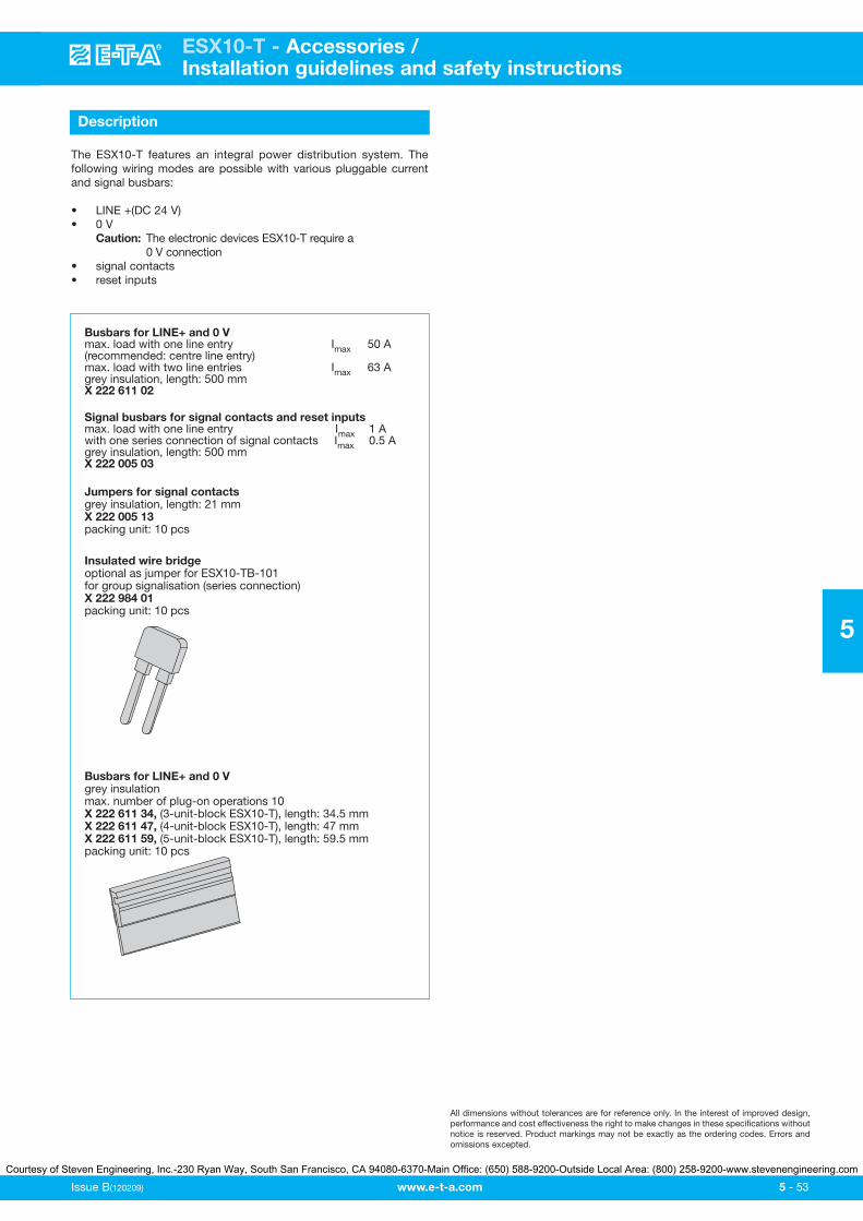
www.e-t-a.com
ESX10-T - Accessories / Installation guidelines and safety instructions
Issue B(120209) 5 - 53
5
Description
The ESX10-T features an integral power distribution system. Thefollowing wiring modes are possible with various pluggable currentand signal busbars:
• LINE +(DC 24 V)• 0 V
Caution: The electronic devices ESX10-T require a 0 V connection
• signal contacts• reset inputs
All dimensions without tolerances are for reference only. In the interest of improved design,performance and cost effectiveness the right to make changes in these specifications withoutnotice is reserved. Product markings may not be exactly as the ordering codes. Errors andomissions excepted.
Busbars for LINE+ and 0 Vmax. load with one line entry Imax 50 A(recommended: centre line entry)max. load with two line entries Imax 63 Agrey insulation, length: 500 mmX 222 611 02
Signal busbars for signal contacts and reset inputsmax. load with one line entry Imax 1 Awith one series connection of signal contacts Imax 0.5 Agrey insulation, length: 500 mmX 222 005 03
Busbars for LINE+ and 0 Vgrey insulationmax. number of plug-on operations 10X 222 611 34, (3-unit-block ESX10-T), length: 34.5 mmX 222 611 47, (4-unit-block ESX10-T), length: 47 mmX 222 611 59, (5-unit-block ESX10-T), length: 59.5 mmpacking unit: 10 pcs
Insulated wire bridgeoptional as jumper for ESX10-TB-101for group signalisation (series connection)X 222 984 01packing unit: 10 pcs
Jumpers for signal contactsgrey insulation, length: 21 mmX 222 005 13packing unit: 10 pcs
Courtesy of Steven Engineering, Inc.-230 Ryan Way, South San Francisco, CA 94080-6370-Main Office: (650) 588-9200-Outside Local Area: (800) 258-9200-www.stevenengineering.com