electronic copy - muna noor · pdf filereaders are advised to check the validity of this...
TRANSCRIPT

Readers are advised to check the validity of this Certificate by either referring to the BBA’s website (www.bbacerts.co.uk) or contactingthe BBA direct (Telephone Hotline 01923 665400).
1 The Building Regulations 1991 (as amended) (England and Wales)
The Secretary of State has agreed with the British Board of Agrémentthe aspects of performance to be used by the BBA in assessing thecompliance of drainage systems with the Building Regulations. In the
opinion of the BBA, the OsmaDrain Underground Drainage System, if used inaccordance with the provisions of this Certificate, will meet the relevantrequirements.Requirement: H1(1) Sanitary pipework and drainage
Comment: See the marked sections of the Design Data parts in theaccompanying Detail Sheets.
Requirement: H3 Rainwater drainage
Comment: See the marked sections of the Design Data parts in theaccompanying Detail Sheets.
Requirement: Regulation 7 Materials and workmanship
Comment: The system is acceptable.
Wavin Building Products LtdParsonage WayChippenhamWilts SN15 5PNTel: 01249 654121 Fax: 01249 443286
AgrémentCertificate
No 87/1835Second issue*
Designated by Governmentto issue
European TechnicalApprovals
OSMADRAIN UNDERGROUND DRAINAGE SYSTEMEléments de drainage souterrainsDränungssystem
Product
Building Regulations — Detail Sheet 1• THIS CERTIFICATE RELATESTO THE OSMADRAIN110 mm AND 160 mmUNDERGROUND DRAINAGESYSTEM, THE COMPONENTSOF WHICH ARE REFERRED TOIN THE ACCOMPANYINGDETAIL SHEETS.• The system is for use indomestic drains and publicand private sewers.• Components of the systemcan be used individually or incombinations as described inthe Detail Sheets.• This Certificate does notcover the use of any of theproducts for untreated tradeeffluents.
CI/SfB
(52) In6
Electronic Copy

2
2 The Building Standards (Scotland) Regulations 1990 (as amended)
In the opinion of the BBA, the OsmaDrain Underground DrainageSystem, if used in accordance with the provisions of this Certificate, willsatisfy the various Regulations as listed below.
Regulation: 10 Selection and use of materials and componentsStandards: B2.1, B2.2 Selection and use of materials and components
Comment: The system is acceptable.Standard: M2.1 Drainage system of a building
Comment: The system can meet the relevant requirements of thisStandard. See the marked sections of the Design Data parts inthe accompanying Detail Sheets.
3 The Building Regulations (Northern Ireland) 1994 (as amended)
In the opinion of the BBA, the OsmaDrain Underground DrainageSystem, if used in accordance with the provisions of this Certificate, willsatisfy the various Regulations as listed below.
Regulation: B2 Fitness of materials and workmanship
Comment: The system is acceptable.Regulation: Part N2 Drainage, systems
Comment: The system satisfies the relevant requirements of thisRegulation. See the marked sections of the Design Data partsin the accompanying Detail Sheets.
Electronic Copy

Conditions of Certification
4 Conditions4.1 This Certificate:(a) relates only to the product that is described,installed, used and maintained as set out in thisCertificate;(b) is granted only to the company, firm or personidentified on the front cover — no other company,firm or person may hold or claim any entitlement tothis Certificate; (c) is copyright of the BBA.
4.2 References in this Certificate to any Act ofParliament, Regulation made thereunder, Directiveor Regulation of the European Union, StatutoryInstrument, Code of Practice, British Standard,manufacturers’ instructions or similar publication,shall be construed as references to such publicationin the form in which it was current at the date ofthis Certificate.
4.3 This Certificate will remain valid for anunlimited period provided that the product and themanufacture and/or fabricating process(es) thereof:(a) are maintained at or above the levels whichhave been assessed and found to be satisfactoryby the BBA;(b) continue to be checked by the BBA or itsagents; and
(c) are reviewed by the BBA as and when itconsiders appropriate.
4.4 In granting this Certificate, the BBA makes norepresentation as to:(a) the presence or absence of any patent orsimilar rights subsisting in the product or any otherproduct; (b) the right of the Certificate holder to market,supply, install or maintain the product; and(c) the nature of individual installations of theproduct, including methods and workmanship.
4.5 Any recommendations relating to the use orinstallation of this product which are contained orreferred to in this Certificate are the minimumstandards required to be met when the product isused. They do not purport in any way to restate therequirements of the Health & Safety at Work etcAct 1974, or of any other statutory, common lawor other duty which may exist at the date of thisCertificate or in the future; nor is conformity withsuch recommendations to be taken as satisfying therequirements of the 1974 Act or of any present orfuture statutory, common law or other duty of care.In granting this Certificate, the BBA does notaccept responsibility to any person or body for anyloss or damage, including personal injury, arisingas a direct or indirect result of the installation anduse of this product.
3
In the opinion of the British Board of Agrément, the OsmaDrain Underground Drainage Systemis fit for its intended use provided it is installed, used and maintained as set out in thisCertificate. Certificate No 87/1835 is accordingly awarded to Wavin Building Products Ltd.
On behalf of the British Board of Agrément
Date of Second issue: 24th December 1998 Director
*Original Certificate issued 29th April 1987, this revised version issued to include updated telephone number, thefacsimile number, reference to the revised national Building Regulations and new Conditions of Certification.
Electronic Copy

British Board of AgrémentP O Box No 195, Bucknalls LaneGarston, Watford, Herts WD2 7NGFax: 01923 665301
©1999 For technical or additionalinformation, tel: 01923 665300.For information about AgrémentCertificate validity and scope, tel:Hotline: 01923 665400
e-mail: [email protected]://www.bbacerts.co.uk
Electronic Copy

Readers are advised to check the validity of this Detail Sheet by either referring to the BBA’s website (www.bbacerts.co.uk) or contactingthe BBA direct (Telephone Hotline 01923 665400).
BS 4660 : 1973 Specification for unplasticized PVC underground drainpipe and fittings — Nominal sizes of 110 mm and 160 mm. Materials,material colour, dimensions, marking, sampling and tests on pipe, fittingsand assemblies. Notes for guidance on storage, handling and installation.Kitemark certified pipe and fittings Manufacturer’s Nominal sizeto BS 4660 : 1973* catalogue No** (mm)
Plain ended pipe 3m 4D 073/A/B/C 1106m 4D 076/A/B/C 1103m 6D 073/A/B/C 1606m 6D 076/A/B/C 160
D/S pipe coupler 4D 205/A 1106D 205/A 160
S/SW pipe coupler 4D 124/A 1106D 124/A 160
D/S slip coupler 4D 105/A 1106D 105/A 160
S/S adaptor to cast iron 4D 107/A 110or clay socket 6D 107/A 110
S/S adaptor to cast iron 4D 128/A 110or clay spigot 6D 128/A 160
SS reducer 4D 095/A 110 x 826D 099/A 160 x 110
S/S 11½° short radius 4D 168/B 110bend
S/S 15° short radius 4D 167/A 110bends 6D 167/A 160
S/S 30° short radius 4D 166/A 110bends 6D 166/A 160
S/S 45° short radius 4D 163/A 110bends 6D 163/A 160
S/S 67½° short radius 4D 162/A 110bends
S/S 87½° short radius 4D 161/A 110bends 6D 161/A 160
D/S 11¼° short radius 4D 568/B 110bends
D/S 15° short radius 4D 567/A 110bends 6D 567/A 160
D/S 30° short radius 4D 566/A 110bends 6D 566/A 160
D/S 45° short radius 4D 563/A 110bends 6D 563/A 160
D/S 67½° short radius 4D 562/A 110bends
D/S 87½° short radius 4D 561/A 110bends 6D 561/A 160
S/S 45° long radius 4D 183/A 110bends 6D 183/A 160
D/S 45° long radius 4D 583/A 110bends 6D 583/A 160
D/S 87½° long radius 4D 581/A 110test bend
Wavin Building Products Ltd Certificate No 87/1835
DETAIL SHEET 2
BSI Kitemarked Components
CI/SfB
(52) In6
OSMADRAIN UNDERGROUND DRAINAGESYSTEM
• THIS DETAIL SHEET LISTS THE COMPONENTS IN THE OSMADRAIN UNDERGROUND DRAINAGESYSTEM CURRENTLY COVERED BY THE BSI KITEMARK CERTIFICATION SCHEME.
BSI Kitemark Licence No 7091 issued to Wavin Building Products Ltd,Parsonage Way,Chippenham, Wilts SN15 5PN.
BSI Kitemark Licence No 5452 issued to Wavin Building Products Ltd,Cobbs Wood, Ashford, Kent TN23 1EL.
BSI Kitemark Licence No 6000 issued to Wavin Industrial Products Ltd,Meadowfield Industrial Estate,Brandon, Durham DH7 8RJ.
continued
Electronic Copy

S/S 87½° long radius 4D 181/D 110bend
P/E 90° long radius 6D 281/A 160bend
S/S 45° equal 4D 210/A 110junctions 6D 210/A 160
S/S 45° unequal 6D 218/A 160 x 100junctions
S/S 87½° equal 4D 190/A 110junctions 6D 190/A 160
S/S 87½° unequal 6D 198/A 160 x 100junctions
D/S 45° equal 4D 213/A 110junctions 6D 213/A 160
D/S 45° unequal 6D 219/A 160 x 110junctions
D/S 87½° equal 4D 193/A 110junctions 6D 193/A 160
S/S inspection pipes 4D 420/B 1106D 420/D 160
S/S equal single 4D 441/B 110inspection junctions 4D 451/B 110
6D 441/D 1606D 451/D 160
S/S 45° equal double 6D 492/D 160inspection junction
D/S inspection pipes 4D 520/B 1106D 520/D 160
D/S 45° equal single 4D 541/C 110inspection junctions 4D 551/C 110
6D 541/D 1606D 551/D 160
D/S 45° equal double 4D 592/C 110inspection junctions 6D 592/D 160
D/S 45° equal twin 4D 542/D 110inspection junctions 4D 552/D 110
D/S 45° equal double 4D 594/D 110twin inspection junction
S/S 87½° short radius 4D 169/A 110access bend with screwed access
D/S 87½° short radius 4D 569/A 110access bend with screwed access
S/S access pipe 6D 274/A 160S/S screwed access 4D 292/A 110
covers 6D 292/A 160Socket plugs 4D 296/A 110D/S 87½° equal single 4D 593/A 110
access junctionS/S 15° channel branch 6D 776/D 160
bends 6D 777/D 160S/S 30° channel branch 6D 778/D 160
bends 6D 779/D 160S/S 45° channel branch 6D 780/D 160
bends 6D 781/D 160S/S 87½° channel branch 6D 784/D 160
bends 6D 785/D 160SW/½S 45° equal 4D 794/D 110
channel junctions 4D 795/D 110SW/½S 87½° equal 4D 792/D 110
channel junctions 4D 793/D 110SW/½S 45° unequal 6D 798/D 160 x 110
channel junctions 6D 799/D 160 x 110SW/½S 87½° unequal 6D 796/D 160 x 110
channel junctions 6D 797/D 160 x 110SW/½S half connectors 4D 864/D 110
6D 864/D 160SW/½S access pipes 4D 868/D 110
6D 868/D 160P/E channel access pipes 4D 874/D 110
6D 874/D 160D/S 90° 4D 585/D 110
channel bends 6D 585/D 160
2
continued
continued
Electronic Copy

D/S 45° long radius 4D 587/D 110channel bends 6D 587/D 160
Socket plug with open boss socket 4D 297/D 110S/S screwed access cover 4D 290/B 110S/S screwed access cover 6D 290/B 160S/S adjustable bend — LH 4D 782/B 110S/S adjustable bend — RH 4D 783/B 110D/S unequal junction 87½° 6D 199/A 160
3
continued
BS 497 : Part 1 : 1976 Specification for manhole covers, road gullygratings and frames for drainage purposes — Cast iron and cast steel— Materials, workmanship, proptective coating, quality control,inspection, marking, grading, dimensions and design features.Appendices detail loading tests and summarize optional variations.Kitemark certified pipe and fittings Manufacturer’s Nominal sizeto BS 497 : Part 1 : 1976* catalogue No** (mm)
Cast iron cover and frame 4D 344/E 110— single seal
Cast iron cover and frame 4D 346/E 110— double seal
BS 4514 : 1983 Specification for unplasticized PVC soil and ventilatingpipes, fittings and accessories — Applies to unplasticized PVC soil andventilating pipe, fittings and accessories, including coated metal fittings,and jointing materials for use in above ground drainage systems intendedto convey normal domestic effluents and surface rainwater.Kitemark certified pipe and fittings Manufacturer’sto BS 4514 : 1983* catalogue No**
P/E 90° WC connector with access 4D 761/F
SW/S 90° WC connector with access 4D 762/F
BSI Kitemark Licence No 7133 issued to Brickhouse Dudley Manufacturing(Fareham) Ltd, 2 Quay Street,Fareham, Hampshire PO16 0LP.
BSI Kitemark Licence No 5314 issued to Wavin Building Products Ltd,Cobbs Wood, Ashford, Kent TN23 1EL.
*Details of Kitemark certification schemes can be obtained from Certification and Assessment Service Quality Assurance Services,British Standards Institution, P O Box 375, Milton Keynes MK14 6LO. Tel: Milton Keynes (0908) 315555; Telex: 82782.
** The letter after the manufacturer’s catalogue number refers to the products covered by the following BSI Kitemark Licences:.
A — Nos 5452, 6000 and 7091B — Nos 5452 and 6000C — No 5452D — No 6000E — No 7133F — No 5314
Electronic Copy

On behalf of the British Board of Agrément
Date of issue: 29th April 1987 Director
Key to abbreviations:
P/E both ends plain or with one plain end and one special endS/S one or more ring seal or push fit socket, but always with one plain or special endD/S ring seal or push fit sockets at all endsS/SW one or more ring seal sockets, but always with one solvent socketSW/S one solvent socket and one plain or special endD/SW solvent sockets at all endsSW/½S half spigot or half socket ends
British Board of AgrémentP O Box No 195, Bucknalls LaneGarston, Watford, Herts WD25 9BAFax: 01923 665301
©1987For additional information about theCertificate, tel: 01923 665300.For information about AgrémentCertificate validity and scope,tel: Hotline 01923 665400, orcheck the BBA website.
e-mail: [email protected]: www.bbacerts.co.uk
Recreated in QX 12.3.03 (sm)
Electronic Copy

Readers are advised to check the validity of this Detail Sheet by either referring to the BBA’s website (www.bbacerts.co.uk) or contactingthe BBA direct (Telephone Hotline 01923 665400).
Installation
1 GeneralInstallation should be carried out in accordancewith BS 5955 : Part 6 : 1980, BS EN 1610 :1998, and BS EN 752 Parts 1 to 4.
2 Laying pipesOn trench bottom in granular material (see Figure 1)
Figure 1 Pipes laid on trench bottom
2.1 Where the as-dug material is suitable* for useas bedding, the bottom of the trench may betrimmed to form the pipe bed.
*Suitable material is defined as granular material inaccordance with the recommendations of BS 5955 : Part 6 :1980, Appendix A, having a nominal particle size not
exceeding 10 mm or 14 mm for 110 mm diameter and160 mm diameter pipes, respectively.
2.2 Small depressions should be made toaccommodate the pipe sockets or couplings. After thepipe has been laid these should be carefully filled toensure that no voids remain under the socket.
2.3 When the formation is prepared, the pipesshould be laid upon it true to line and level within thespecified tolerances. Each pipe should be checkedand any necessary adjustments to level made byraising or lowering the formation, ensuring that thepipes finally rest evenly on the adjusted formationthroughout the length of the barrels. Adjustmentshould never be made by local packing.
2.4 Where the formation is low and does notprovide continuous support, it should be brought upto the correct level by placing and compactingsuitable material.
On granular beds (see Figures 2 and 3)
Figure 2 Pipes laid on 50 mm minimum pea gravelbedding
see section 2.7 forsoil specificationrequirements
first 300 mm ofbackfill selected tobe free fromstones exceeding40 mm (unless thegranular materialexceeds 100 mmabove the pipecrown – see noteopposite)
pea gravel sidefill(see section 3)
minimum 50 mmpea gravel
where the backfillabove the pipe con-tains stones largerthan 40 mm orwhere the pipeworkis deeper than 2 min poor ground, theselected granularmaterial shouldextend to at least100 mm above thepipe crown
sidefill minimum150 mm wideeach side of piperegardless ofdiameter
Note: As-dug soil, sidefill and backfill to be granularmaterial to BS 5955 : Part 6 : 1980 (see section 2.1)
trench bottom trimmed and loosened to form bed
pipe diameter sidefill
backfill
as-dug soil
• THIS DETAIL SHEET RELATES TO THE INSTALLATION OF KITEMARKEDOSMADRAIN 110 mm AND 160 mm DIAMETER PVC-UUNDERGROUND DRAIN PIPES AND FITTINGS TO BS EN 1401-1 :1998 AND BS 4660 : 1989 (SEE DETAIL SHEET 2) AND PRODUCTSCERTIFICATED BY THE BBA AS DESCRIBED IN THIS CERTIFICATE.
Certificate No 87/1835
DETAIL SHEET 3Second issue*
Wavin Building Products Ltd
OSMADRAIN UNDERGROUNDDRAINAGE SYSTEM — INSTALLATION
Product
CI/SfB
(52) In6
Electronic Copy
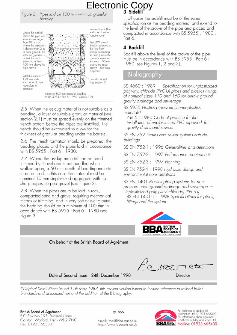
Figure 3 Pipes laid on 100 mm minimum granularbedding
2.5 When the as-dug material is not suitable as abedding, a layer of suitable granular material (seesection 2.1) must be spread evenly on the trimmedtrench bottom before the pipes are installed. Thetrench should be excavated to allow for thethickness of granular bedding under the barrels.
2.6 The trench formation should be prepared, thebedding placed and the pipes laid in accordancewith BS 5955 : Part 6 : 1980.
2.7 Where the as-dug material can be handtrimmed by shovel and is not puddled whenwalked upon, a 50 mm depth of bedding materialmay be used. In this case the material must benominal 10 mm single-sized aggregate with nosharp edges, ie pea gravel (see Figure 2).
2.8 When the pipes are to be laid in rock,compacted sand and gravel requiring mechanicalmeans of trimming, and in very soft or wet ground,the bedding should be a minimum of 100 mm inaccordance with BS 5955 : Part 6 : 1980 (seeFigure 3).
3 SidefillIn all cases the sidefill must be of the samespecification as the bedding material and extend tothe level of the crown of the pipe and placed andcompacted in accordance with BS 5955 : 1980 :Part 6.
4 BackfillBackfill above the level of the crown of the pipemust be in accordance with BS 5955 : Part 6 :1980 (see Figures 1, 2 and 3).
Bibliography
BS 4660 : 1989 — Specification for unplasticizedpolyvinyl chloride (PVC-U) pipes and plastics fittingsof nominal sizes 110 and 160 for below groundgravity drainage and sewerageBS 5955 Plastics pipework (thermoplasticsmaterials)
Part 6 : 1980 Code of practice for theinstallation of unplasticized PVC pipework forgravity drains and sewers
BS EN 752 Drains and sewer systems outsidebuildings
BS EN 752-1 : 1996 Generalities and definitions
BS EN 752-2 : 1997 Performance requirements
BS EN 752-3 : 1997 Planning
BS EN 752-4 : 1998 Hydraulic design andenvironmental considerations
BS EN 1401 Plastics piping systems for non-pressure underground drainage and sewerage —Unplasticized poly (vinyl chloride) (PVC-U)
BS EN 1401-1 : 1998 Specifications for pipes,fittings and the system
see section 2.8 forsoil specificationrequirements
first 300 mm ofbackfill selected tobe free fromstones exceeding40 mm (unless thegranular materialexceeds 100 mmabove the pipecrown – see noteopposite)
granular sidefill(see section 3)
minimum 100 mm granular bedding(to BS 5955 : Part 6 :1980, Clause 7.2)
where the backfillabove the pipe con-tains stones largerthan 40 mm orwhere the pipeworkis deeper than 2 min poor ground, theselected granularmaterial shouldextend to at least100 mm above thepipe crown
sidefill minimum150 mm wideeach side of piperegardless ofdiameter
On behalf of the British Board of Agrément
Date of Second issue: 24th December 1998 Director
*Original Detail Sheet issued 11th May 1987, this revised version issued to include reference to revised BritishStandards and associated text and the addition of the Bibliography.
British Board of AgrémentP O Box No 195, Bucknalls LaneGarston, Watford, Herts WD2 7NGFax: 01923 665301
©1999 For technical or additionalinformation, tel: 01923 665300.For information about AgrémentCertificate validity and scope, tel:Hotline: 01923 665400
e-mail: [email protected]://www.bbacerts.co.uk
Electronic Copy

Readers are advised to check the validity of this Detail Sheet by either referring to the BBA’s website (www.bbacerts.co.uk) or contactingthe BBA direct (Telephone Hotline 01923 665400).
Technical Specification
1 Description1.1 The universal gully is assembled from a rangeof components to allow various inlet and outletarrangements to be made on site. The basiccomponents are the gully trap, hopper and outletbend (see Table 1 and Figures 1, 2 and 3).Dimensions are detailed in Wavin BuildingProducts Ltd’s Product Catalogue, reference BPC 1.
Table 1 Universal Gully and fittings
Manufacturer’s Productcatalogue No
4D 161 Single socket short radius 87½° bend4D 169 Single socket short radius 87½° access bend4D 500 Single socket gully trap4D 503 Solvent weld socket hopper (plain)4D 504 solvent weld socket hopper (vertical inlet)4D 507 Plain ended hopper (plain)4D 508 Plain ended hopper (vertical inlet)4D 525 Sealed access plate (spare)4D 527 Plain ended sealed inspection hopper4D 561 double socket short radius 87½° bend4D 563 Double socket short radius 45° bend4D 569 Double socket short radius 87½° access bend4D 589 Single socket bossed pipe
1.2 The fittings are injection moulded inpolypropylene or uPVC. The uPVC componentscomply with the quality and colour requirements ofBS 4660 : 1973 Specification for unplasticizedPVC underground drain pipe and fittings.Continuous quality control is exercised duringmanufacture and includes checks on stress relief,tensile strength and dimensional accuracy.
1.3 The 110 mm diameter ring seals are SBR(styrene butadiene rubber) to BS 2494 : 1986Specification for elastomeric joint rings forpipework and drainage.
1.4 Some of the items used to construct theuniversal gully are kitemarked to BS 4660 : 1973(see Detail Sheet 2).
2 Delivery and site handling2.1 The components are delivered to site in plasticbags containing similar items. The packagingshould be retained during storage to minimise therisk of loss or damage.
2.2 If long term storage in the open is envisagedthen the fittings should be shaded from directsunlight.
2.3 A label is fixed to each gully bearing the BBAidentification mark incorporating the number of thisCertificate.
• THIS DETAIL SHEET REPLACES PART OF CERTIFICATE No 84/1371AND RELATES TO THE OSMADRAIN UNIVERSAL GULLY.• The gully is for use with 110 mm uPVC underground drain pipes andfittings to BS 4660 : 1973, to receive surface water from paved areasinaccessible to wheeled vehicles, surface water from roofs and/or wastewater from ground floor domestic appliances.
This Detail Sheet must be read in conjunction with the Front Sheet and DetailSheet 1 which give Conditions of Certification and the product’s positionregarding the Building Regulations respectively.
Certificate No 87/1835
DETAIL SHEET 7Wavin Building Products Ltd
OSMADRAIN UNIVERSAL GULLY
Product
CI/SfB
(52) In6
Electronic Copy

Figure 1 Typical combinations for use with universal gully
Figure 2 Alternative assemblies
2
Electronic Copy

Design Data
3 GeneralThe OsmaDrain Universal Gully is suitablefor use in domestic drains designed inaccordance with BS 8301 : 1985 Code of
practice for building drainage for the conveyance,by combined or separate systems, of surface wateras is permitted to be discharged into public sewersby the Public Health Act 1936, and surface wateras is permitted and defined by the Sewerage(Scotland) Act 1968 and the Water andSewerage Services (Northern Ireland) Order1973.
4 Strength
The universal gully has adequate strength toresist loads associated with installation andfor subsequent use in situations inaccessible
to wheeled vehicles.
5 Performance of joints
5.1 Joints between the access systems,universal gully and drainage systemscomplying with BS 4660 : 1973 will
remain watertight under conditions of deformationand pipeline deflection in excess of those expectedto occur with normal good drainage practice.
3
Figure 3 Detail of hoppers
Electronic Copy

5.2 The dimensions of sockets and sealing ringsare such as to give satisfactory joints. Theperformance of the joints will not be affected bythermal movement when the system is correctlyinstalled and limited to the conditions of use set outin this Detail Sheet.
6 Flow characteristics6.1 The gully has adequate flowcharacteristics and will retain an effectivewater seal in conditions of induced or self-
siphonage in excess of those associated with gooddrainage practice.
6.2 The sealed access hopper remains airtightunder normal service conditions.
7 Resistance to chemicalsThe universal gully will be unaffected bythose types and quantities of chemicalsassociated with waste water and surface
water.
8 Resistance to elevated temperaturesThe gully has adequate resistance totemperatures which are likely to be found inwaste and surface water.
9 RoddingIf access is required for rodding the drainfrom a position near the gully, an accessbend (4D 569) and a cast iron cover and
frame assembly 4D 324 must be used (see Figure4a). The drain cannot be rodded through theuniversal gully.
10 MaintenanceRemoval of the grating or sealed access plate willallow access to the gully trap for the removal ofdebris provided the recommended installationdepths are not exceeded.
11 DurabilityIn the opinion of the BBA, when used in the contextof this Detail Sheet, the materials from which thecomponents are manufactured will not significantlydeteriorate, and the system will have a life inexcess of 50 years.
4
Figure 4 Typical installation details
Installation
12 Procedure12.1 Installation of the OsmaDrain Universal Gullymust be in accordance with BS 5955 : Part 6 :1980 Plastics pipework (thermoplastics materials)— Code of practice for the installation ofunplasticized PVC pipework for gravity drains andsewers, BS 8301 : 1985 and Wavin BuildingProducts Ltd’s OsmaDrain Installation Guidepublication BIG 1, October 1986.
12.2 Precautions must be taken during and afterinstallation to protect the gully arrangements fromdamage due to site traffic.
12.3 The universal gully must be assembledabove ground and then positioned on levelledbricks or a prepared concrete slab. The trap is thenbedded and surrounded in concrete to give fullsupport to the base. Connections are then madeand the assembly backfilled as shown in Figures 3,4 and 5 with suitable granular material.
Electronic Copy

Figure 5 Arrangements for particular use
5
Electronic Copy

12.4 The crown of the outlet bend from the gullymust be below the level to which gardenimplements can penetrate when it is not protectedby paving or concrete at ground level. When this isnot practicable a concrete slab should be beddedabove the bend (see Figure 4b).
12.5 The depth from ground level to the base ofthe trap should not exceed 600 mm to facilitate theremoval of debris.
Technical Investigations
The following is a summary of the technicalinvestigations carried out on the OsmaDrainUniversal Gully.
13 TestsTests were carried out to determine:
dimensional accuracyeffect of thermal cycling to BS 4514 : 1969
Unplasticized PVC soil and ventilating pipe,fittings and accessories
Vicat softening pointimpact resistancepracticability of installationwatertightnessairtightness.
14 Other investigations14.1 An evaluation of existing data was made toassess the following:
resistance to chemicalssuitability of materialsdurabilityeffect of syphonage on trap seal loss
14.2 The manufacturing process was examinedincluding the methods adopted for quality controland details were obtained of the quality andcomposition of materials used.
14.3 An assessment was made of the flowcharacteristics.
14.4 A site visit was undertaken to assess thepracticability of the installation instructions.
On behalf of the British Board of Agrément
Date of isssue: 29th April 1987 Director
Recreated in QX 12.3.03 (sm)
British Board of AgrémentP O Box No 195, Bucknalls LaneGarston, Watford, Herts WD25 9BAFax: 01923 665301
©1987For additional information about theCertificate, tel: 01923 665300.For information about AgrémentCertificate validity and scope,tel: Hotline 01923 665400, orcheck the BBA website.
e-mail: [email protected]: www.bbacerts.co.uk
Electronic Copy

Readers are advised to check the validity of this Detail Sheet by either referring to the BBA’s website (www.bbacerts.co.uk) or contactingthe BBA direct (Telephone Hotline 01923 665400).
Technical Specification
1 Description1.1 The OsmaDrain adjustable bend (seeFigures 1 and 2) incorporates two mouldingspressed together to retain a sealing ring. The twocomponents may be rotated to form any anglebetween 0° and 30°. The 4D 173 bend has asocket inlet and spigot outlet, the 4D 573 bend isa double socket fitting. Each socket incorporates aring seal retained by a snap cap. The productshave an arrow indicating the direction of flow.
Figure 1 Single socket adjustable bend
Figure 2 Double socket adjustable bend
1.2 The fitting body and snap cap are injectionmoulded in polypropylene.
1.3 Quality control checks, including visualdimensional checks, heat reversion and waterpressure resistance tests, are carried outcontinuously during manufacture.
1.4 The sealing rings are Type WCBS EN 681-1 : 1996.
1.5 Each fitting is stamped with the manufacturer’sname and product code number. A label bearingthe BBA identification mark incorporating thenumber of this Certificate is attached to each fitting.
4D.573
97
97
184
• THIS DETAIL SHEET RELATES TO THE OSMADRAIN 4D 173 AND4D 573 110 mm DIAMETER POLYPROPYLENE ADJUSTABLE BENDS.• The adjustable bends are for use with pipes and fittings complying withBS EN 1401-1 : 1998, BS 4660 : 1989 and BS 7158 : 1989, andwith the components referred to in the accompanying Detail Sheets.
This Detail Sheet must be read in conjunction with the Front Sheet and DetailSheet 1, which give the Conditions of Certification and the products’ positionregarding the Building Regulations, respectively.
Certificate No 87/1835
DETAIL SHEET 10Second issue*
Wavin Building Products Ltd
OSMADRAIN 110 mmADJUSTABLE BENDS
Product
CI/SfB
(52) In6
Electronic Copy

2 Delivery and site handlingThe fittings are delivered to site in polythene bags.This packaging should be retained during storageto minimise the risk of damage to component parts.
Design Data
3 GeneralThe 110 mm diameter adjustable bendshave been assessed for use with pipes andfittings complying with BS EN 1401-1 :
1998, in domestic drains designed in accordancewith BS EN 752 : 1996 : Parts 1 to 4, BS 4660 : 1989 and BS 7158 : 1989 for theconveyance, by combined or separate systems, ofsurface water and domestic sewage as is permittedto be discharged into public sewers by the WaterIndustry Act 1991 Chapter 56 and surface waterand sewage as is permitted and defined by theSewerage (Scotland) Act 1968 and the Waterand Sewerage Services (Northern Ireland) Order1973.
4 StrengthThe adjustable bends have adequatestrength to resist those loads associated withinstallation and with subsequent use in
locations defined in this Detail Sheet.
5 Performance of joints5.1 The performance of joints will not beadversely affected by thermal expansion orcontraction when correctly made.
5.2 Joints with the pipeline remain watertightunder conditions of pipeline movement in excess ofthose expected to occur in normal good drainagepractice.
6 Flow characteristicsWhen used in underground drainagesystems designed and installed inaccordance with the recommendations given
in this Detail Sheet, the adjustable bend will notadversely affect the flow characteristics of thesystem.
7 Resistance to chemicals7.1 The products are suitable for use wherepipes and fittings to BS EN 1401-1 : 1998and BS 4660 : 1989 are normally used.
They have adequate resistance to the type andquantity of chemicals likely to be found in domesticsewage.
7.2 Details of the chemical resistance ofpolypropylene are given in BS Code ofPractice 312 : Part 1 : 1973.
8 Resistance to elevated temperaturesThe products are for use where pipes andfittings to BS EN 1401-1 : 1998, BS 4660 : 1989 and BS 7158 : 1989 are
normally used and have adequate resistance to thetemperatures likely to be found in domesticsewage.
9 Practicability of installationThe products are installed easily undernormal site conditions and are rotated easilyto the required angle.
10 RoddingDrains incorporating the product can berodded easily using conventional flexibledrain rods. Toothed root cutters, as used with
some mechanical cleaning systems, could damagethe fittings and these should not be used.
11 DurabilityIn the opinion of the BBA, when used in thecontext of this Detail Sheet, no significantdeterioration of the product will take place
and installations have a life in excess of 50 years.
Installation
12 General12.1 Installation of the OsmaDrain 110 mmAdjustable Bend must be in accordance with themanufacturer’s installation instructions, and DetailSheet 3 of this Certificate.
12.2 Installations using the product are shown inFigures 3 to 7.
2
Electronic Copy

Figure 3 Installation of single socket adjustablebend
Figure 4 Permissible connections to inspectionchamber
s/s adjustable bends(4D.173)
Note: The bends must be fitted adjacent to the inspection chamber
s/s adjustable bends (4D.173)
3
Electronic Copy

Figure 5 Double socket bend — change in gradient
4
Figure 6 Double socket bend — manhole base
Electronic Copy

Figure 7 Installation procedure (typical)
13 Procedure13.1 Joints are made as follows:(a) The components to be joined are lined up.The flow direction indicator must point in thedirection of flow.(b) The fitting is rotated to the approximate anglerequired.(c) Both socket and pipe or spigot must becleaned.(d) The ring seal must be correctly seated.
(e) The recommended lubricant is applied to thepipe or spigot.(f) The pipe is inserted fully into the socket andapproximately 10 mm is withdrawn to allow forexpansion.(g) It is important to ensure that the invert of thefitting follows the required gradient.
13.2 Drain and sewer systems utilising the bendsshould be installed in accordance with DetailSheet 3 of this Certificate.
13.3 The systems must have adequate protectionagainst damage from site construction traffic andfrom agricultural or similar operations.
Technical Investigations
The following is a summary of the technicalinvestigations carried out on the OsmaDrain110 mm Adjustable Bend.
14 TestsTests were carried out to determine:effect of combined hot and cold water discharges
through the product whilst subjected to a loadingof 35 kN (BS 4660 : 1973 Appendix K)
dimensional accuracywatertightness of joints under conditions of pipe
deformation and hydrostatic pressure of 0.35bar
watertightness of joints under conditions of verticaldisplacement and a hydrostatic pressure of 0.35bar
ease of jointing and rotating to angle requiredwatertightness of central joint when subject to shear
loadseffect of rodding using polypropylene drain rods
with various rodding heads.
15 Other investigations15.1 An evaluation of existing data was made toassess:tensile strengthcompressive strengthimpact strengthVicat softening pointresistance to chemicalsflow characteristicsdurability.
15.2 The manufacturing process was examined,including the methods adopted for quality control,and details were obtained of the quality andcomposition of the materials used.
15.3 A visit was made to a site in progress toassess the practicability of installation.
pipe to be connected to inspection chamber
maximum 30°
stage 1determine approximate angle required
stage 2set fitting to approximate angle required ensuring that the arrow
points in direction of flow
stage 3complete installation ensure that invert of fitting is to required gradient�
5
Electronic Copy

Bibliography
BS 4660 : 1989 Specification for unplasticizedpolyvinyl chloride (PVC-U) pipes and plastics fittingsof nominal sizes 110 and 160 for below groundgravity drainage and sewerageBS 7158 : 1989 Specification for plasticsinspection chambers for drainsBS EN 681 Elastomeric seals : Materialrequirements for pipe joint seals used in water anddrainage applicationsBS EN 681-1 : 1996 Vulcanized rubberBS EN 752 Drains and sewer systems outsidebuildingsBS EN 752-1 : 1996 Generalities and definitions
BS EN 752-2 : 1997 Performance requirementsBS EN 752-3 : 1997 PlanningBS EN 752-4 : 1998 Hydraulic design andenvironmental considerationsBS EN 1401 Plastics piping systems for non-pressure underground drainage and sewerage —Unplasticized poly (vinyl chloride) (PVC-U)BS EN 1401-1 : 1998 Specifications for pipes,fittings and the systemBS Code of Practice 312
Part 1 : 1973 Code of Practice for Plasticspipework (thermoplastics material) — Generalprinciples and choice of material
On behalf of the British Board of Agrément
Date of Second issue: 24th December 1998 Director
*Original Detail Sheet issued 17th November 1988, this revised version issued to include reference to revised BritishStandards and associated text and the addition of the Bibliography.
British Board of AgrémentP O Box No 195, Bucknalls LaneGarston, Watford, Herts WD2 7NGFax: 01923 665301
©1999 For technical or additionalinformation, tel: 01923 665300.For information about AgrémentCertificate validity and scope, tel:Hotline: 01923 665400
e-mail: [email protected]://www.bbacerts.co.uk
Electronic Copy

Readers are advised to check the validity of this Detail Sheet by either referring to the BBA’s website (www.bbacerts.co.uk) or contactingthe BBA direct (Telephone Hotline 01923 665400).
Technical Specification
1 Description1.1 The OsmaDrain Yard Gully comprises a blow-moulded, high density polyethylene (HDPE) gullywith an internal diameter of 305 mm and depth of600 mm (see Figure 1).
Figure 1 Gully details
1.2 The trapped gully incorporates an integraltrap, outlet spigot and an EPDM rubber plug andretaining strap to BS EN 681-1 : 1996, Type W6.
If the access plug is not used, the gully isconsidered to be untrapped.
1.3 A perforated galvanized mild steel catchmentbucket is available for use with the gully (see Figure 2).
Figure 2 Catchment bucket
1.4 A cast iron grating and frame, kitemarked foruse as a Class B125 cover to BS EN 124 :1994, are available for use with the gully (gratingdimensions 303 mm by 325 mm).
1.5 Joints to PVC-U pipe to BS EN 1401-1 :1998 can be made directly from the outlet usingstandard BS EN 1401-1 and BS 4660 : 1989connectors.
1.6 Quality control includes visual examinationson each moulding and checks on dimensions andweight.
2 Delivery to site, handling and storageThe OsmaDrain Yard Gully is delivered to siteunprotected and is identified by the manufacturer’sproduct code and a label bearing the BBAidentification mark incorporating the number of thisCertificate.
A
B A = 225B = 245
all dimensionsin millimetres
B (I.D.)
A
C
D
all dimensions in millimetres
A = 600B = 305C = 305D = 430
• THIS DETAIL SHEET RELATES TO THE OSMADRAIN YARD GULLY.• The product is for use as a trapped gully for connection to 110 mmPVC-U pipes and fittings to BS EN 1401-1 : 1998 and BS 4660 : 1989.• The gully is for use in situations where Class B125 covers toBS EN 124 : 1994 would be suitable.• This Detail Sheet does not cover the use of the gully for domesticsewerage, combined sewerage systems or untreated trade effluents.
This Detail Sheet must be read in conjunction with the Front Sheet and DetailSheet 1, which give the Conditions of Certification and the product’s positionregarding the Building Regulations, respectively.
Certificate No 87/1835
DETAIL SHEET 12Second issue*
Wavin Building Products Ltd
OSMADRAIN YARD GULLY
Product
CI/SfB
(52) In6
Electronic Copy

Design Data
3 General3.1 The gully is for use with pipes andfittings complying with BS EN 1401-1 :1998 and BS 4660 : 1989 in surface
water drainage systems designed in accordancewith BS 6367 : 1983 and BS EN 752 : 1996,Parts 1 to 4, for the conveyance of surface water.
3.2 This Detail Sheet does not cover the use of thegully for domestic sewage, combined seweragesystems or untreated trade effluents.
4 Flow characteristicsThe gully has a nominal holding capacity of26 litres.
5 StrengthThe product has adequate strength to resistloads associated with installation and withsubsequent use in the situations defined in
the Product part of this Detail Sheet.
6 WatertightnessThe connection between the gully and pipesand fittings to BS EN 1401-1 : 1998 andBS 4660 : 1989 is watertight.
7 Rodding and maintenanceThe drain from the gully may be rodded,using flexible drain rods, by removing theaccess plug. To maintain the effectiveness of
the trap the plug must be replaced after rodding.
8 Practicability of installationThe gully is installed easily under normal siteconditions.
9 Resistance to chemicalsThe gully will be unaffected by those typesand quantities of chemicals likely to be foundin surface water.
10 DurabilityThe gully will have a life equivalent to that ofPVC-U drainage systems.
Installation
11 Procedure11.1 The gully should be installed in a suitablysized excavation allowing an additional 150 mmunder and around the gully (see Figure 3).
11.2 A bed of 150 mm granular material is laid.
11.3 The gully is set level and in line with thebranched drain.
11.4 The gully is connected to the branch drainand surrounded by granular material to a maximumdepth of 350 mm.
11.5 The rest of the excavation is filled withconcrete and the grating and frame bedded in asuitable concrete mix.
Figure 3 Typical installation details
Technical Investigations
The following is a summary of the technicalinvestigations carried out on the OsmaDrain YardGully.
12 TestsTests were carried out to determine:dimensional accuracydensity of HDPE to ISO 1183 : 1987, Method AVicat softening temperature to ISO 306 : 1987,
Method Aash content to ISO 1270 : 1975 : Method Atensile strength and elongation to ISO R 527 : 1966melt flow rate of BS 2782 : Part 7 :
Method 720A : 1979watertightness of gully and connectioncapacityresistance to external hydrostatic pressureresistance to wheel loads.
13 Other investigations13.1 An evaluation of existing data was made toassess resistance to chemicals and durability.
250
350
150
pour 150 mm by 250 mminvert of concrete around gully
bed the grating and framein a suitable concrete mix
bed and surround gullyin a minimum of 150 mmgranular material
connect 110 mm OsmaDrainin the appropriate way
all dimensions in millimetres
2
Electronic Copy

13.2 The manufacturing process was examined,including the methods adopted for quality control,and details were obtained of the quality andcomposition of the materials used.
Bibliography
BS 2782 Methods of testing plasticsPart 7 Rhelogical properties
Method 720A : 1979 Determination of meltflow rate of thermoplastics
BS 4660 : 1989 Specification for unplasticizedpolyvinyl chloride (PVC-U) pipes and plastics fittingsof nominal sizes 110 and 160 for below groundgravity drainage and sewerageBS 6367 : 1983 Code of practice for drainage ofroofs and paved areasBS EN 124 : 1994 Gully tops and manhole topsfor vehicular and pedestrian areas — Designrequirements, type testing, marking, quality controlBS EN 752 Drains and sewer systems outsidebuildings
BS EN 752-1 : 1996 Generalities and definitionsBS EN 752-2 : 1997 Performance requirementsBS EN 752-3 : 1997 PlanningBS EN 752-4 Hydraulic design and environmentalconsiderationsISO 306 : 1987 Plastics — Thermoplasticsmaterials — Determination of Vicat softening point :Method ABS EN 1401 Plastics piping systems for non-pressure underground drainage and sewerage —Unplasticized poly (vinyl chloride) (PVC-U)BS EN 1401-1 : 1998 Specifications for pipes,fittings and the systemISO R 527 : 1966 Plastics. Determination oftensile propertiesISO 1183 : 1987 Plastics. Methods fordetermining the density and relative density of non-cellular plastics : Method AISO 1270 : 1975 Plastics. PVC Resins :Determination of ash and sulphated ash :Method A
3
On behalf of the British Board of Agrément
Date of Second issue: 24th December 1998 Director
*Original Detail Sheet issued 7th March 1995. This revised version issued to include reference to revised BritishStandards and associated text and the addition of the Bibliography.
Electronic Copy

British Board of AgrémentP O Box No 195, Bucknalls LaneGarston, Watford, Herts WD2 7NGFax: 01923 665301
©1999 For technical or additionalinformation, tel: 01923 665300.For information about AgrémentCertificate validity and scope, tel:Hotline: 01923 665400
e-mail: [email protected]://www.bbacerts.co.uk
Electronic Copy