electronic diesel control edc 16 - · pdf fileelectronic diesel control edc 16 ... from bosch...
TRANSCRIPT
Service.
Electronic Diesel Control EDC 16
Design and Function
Self-Study Programme 304
2
NEW ImportantNote
This Self-Study Programme explains the design and
function of new developments.
The contents will not be updated.
For the latest testing, adjusting and repair
instructions, please refer to the relevant workshop
literature.
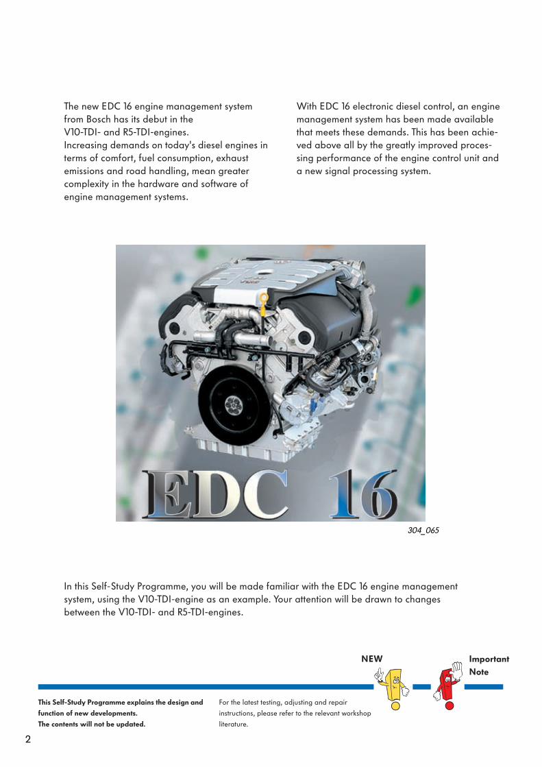
The new EDC 16 engine management system from Bosch has its debut in the V10-TDI- and R5-TDI-engines. Increasing demands on today's diesel engines in terms of comfort, fuel consumption, exhaust emissions and road handling, mean greater complexity in the hardware and software of engine management systems.
In this Self-Study Programme, you will be made familiar with the EDC 16 engine management system, using the V10-TDI-engine as an example. Your attention will be drawn to changes between the V10-TDI- and R5-TDI-engines.
With EDC 16 electronic diesel control, an engine management system has been made availablethat meets these demands. This has been achie-ved above all by the greatly improved proces-sing performance of the engine control unit and a new signal processing system.
304_065

3
Contents
Introduction . . . . . . . . . . . . . . . . . . . . . . . . . . . . . . . . . . . . . . . . . . 4
Engine management . . . . . . . . . . . . . . . . . . . . . . . . . . . . . . . . . . 6
V10-TDI-engine system overview . . . . . . . . . . . . . . . . . . . . . . . . . . . 6Metering regulation . . . . . . . . . . . . . . . . . . . . . . . . . . . . . . . . . . . . . . 8Start of injection regulation . . . . . . . . . . . . . . . . . . . . . . . . . . . . . . 10Exhaust gas recirculation . . . . . . . . . . . . . . . . . . . . . . . . . . . . . . . . . 12Charge pressure control . . . . . . . . . . . . . . . . . . . . . . . . . . . . . . . . . . 15Preglow system . . . . . . . . . . . . . . . . . . . . . . . . . . . . . . . . . . . . . . . . . . 16Idling speed control . . . . . . . . . . . . . . . . . . . . . . . . . . . . . . . . . . . . . . 17Smooth running control . . . . . . . . . . . . . . . . . . . . . . . . . . . . . . . . . . . 18Active pulse damping . . . . . . . . . . . . . . . . . . . . . . . . . . . . . . . . . . . . 19Governor . . . . . . . . . . . . . . . . . . . . . . . . . . . . . . . . . . . . . . . . . . . . . . 20Cruise control system . . . . . . . . . . . . . . . . . . . . . . . . . . . . . . . . . . . . 2
1Sensors . . . . . . . . . . . . . . . . . . . . . . . . . . . . . . . . . . . . . . . . . . . . . . . 22Actuators . . . . . . . . . . . . . . . . . . . . . . . . . . . . . . . . . . . . . . . . . . . . . . 32V10-TDI-engine functional diagram . . . . . . . . . . . . . . . . . . . . . . . 44
Service . . . . . . . . . . . . . . . . . . . . . . . . . . . . . . . . . . . . . . . . . . . . 46
Self-diagnosis . . . . . . . . . . . . . . . . . . . . . . . . . . . . . . . . . . . . . . . . . . 46Workshop equipment . . . . . . . . . . . . . . . . . . . . . . . . . . . . . . . . . . . 47
Test your knowledge . . . . . . . . . . . . . . . . . . . . . . . . . . . . . . . . . 48

4
Introduction
– Start– Idling speed control– Full throttle– Power limitation– Speed governor– Driving comfort– Component protection
304_062
External torque demands
Internal torque demands
Engine control unit J...
Bosch EDC 16
Bosch EDC 16 is a torque-orientated engine management system which is featured for the first time in a diesel engine. As is the case with petrol engines, in the EDC 16 system all torque demands are collected, evaluated and co-ordinated in the engine control unit. This has the advantage of better adaptability between the individual vehicle systems (engine management, brake system, automatic gearbox, air conditioning, ...).
EGR valve N18
Unit injector solenoid valves N240 … 244
Turbocharger 1 positioning motor V280
Turbocharger 2 positioning motor V281
Realisation of torque demands
Automatic gearbox control unit J217
Climatronic control unit J255
ABS with ESP control unit J104
Accelerator pedal module
Cruise control system

5
Functions that cover whole cylinder banks, such as the coolant supply, are carried out byengine control unit 1 J623, or the smooth running control by engine control unit 2 J624.
Information received by engine controlunit 1 J623 is sent to engine control unit 2 J624 via an internal CAN databus.
304_026
Inte
rnal
CA
N
data
bus
304_071
Engine controlunit 1 J623
Engine controlunit 2 J624
The Bosch EDC 16 engine management system is designed to be compatible as both a single and double control unit concept. The actual concept used depends on the number of cylinders in the engine.
– On the R5-TDI-engine, engine control unit 1 J623 fulfils all functions.– On the V10-TDI-engine, engine control unit 1 J623 fulfils the basic functions for cylinder bank 1 and
engine control unit 2 J624 for cylinder bank 2. Basic functions are, for example, actuation of the unit solenoid injector valves and exhaust gas recirculation.
Engine control units in the CAN drive train databus
Both control units are identical and have the same part number. The allocation of engine control unit 1 and engine control unit 2 is done via a coding link in the connector for engine control unit 2. Following allocation, the control units can no longer be changed over.
Engine control
unit 2 J624
Engine control
unit 1 J623
Control unit
for ABS with
ESP J104
Turbocharger 1
positioning
motor V280
Steering column
electronics
control unit J527
Turbocharger 2
positioning
motor V281
Automatic
gearbox control
unit J217
Entry and start
authorisation
control unit J518
Airbag control
unit J234
Control unit with display in dash panelinsert J285
6 7
304_003
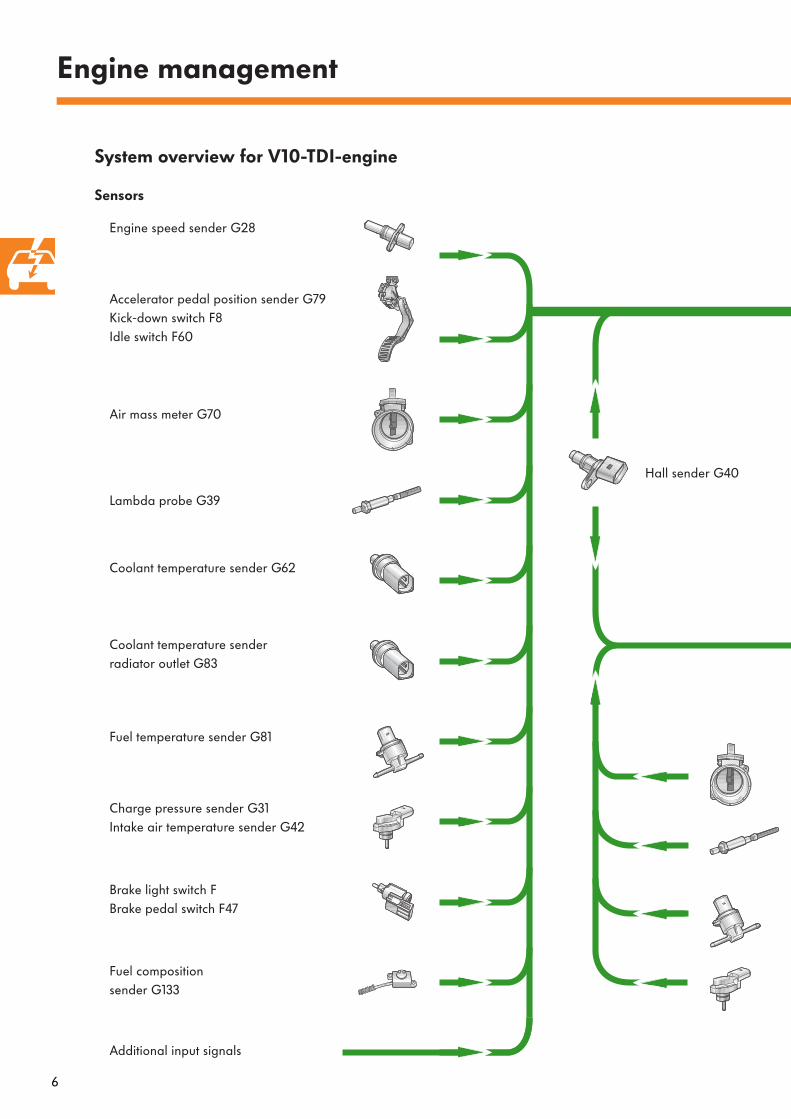
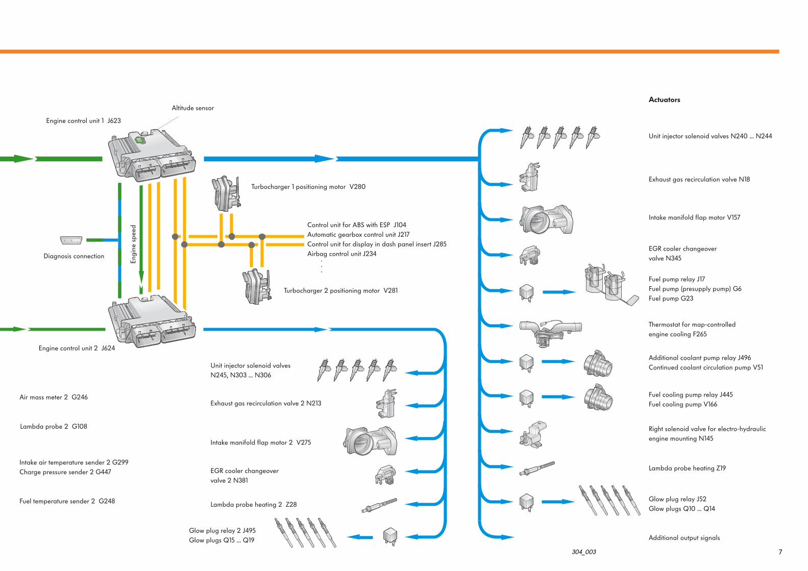
Engine management
System overview for V10-TDI-engine
Air mass meter 2 G246
Fuel temperature sender 2 G248
Intake air temperature sender 2 G299Charge pressure sender 2 G447
Lambda probe 2 G108
Diagnosis connection
Engine control unit 2 J624
Engine control unit 1 J623
Hall sender G40
Engine speed sender G28
Accelerator pedal position sender G79Kick-down switch F8Idle switch F60
Air mass meter G70
Coolant temperature sender G62
Coolant temperature senderradiator outlet G83
Fuel temperature sender G81
Fuel compositionsender G133
Charge pressure sender G31Intake air temperature sender G42
Lambda probe G39
Brake light switch FBrake pedal switch F47
Additional input signals
Sensors
Turbocharger 1 positioning motor V280
Turbocharger 2 positioning motor V281
Altitude sensor
Eng
ine
spee
d Control unit for ABS with ESP J104Automatic gearbox control unit J217Control unit for display in dash panel insert J285Airbag control unit J234
.
.
.
Unit injector solenoid valves N245, N303 ... N306
Exhaust gas recirculation valve 2 N213
Intake manifold flap motor 2 V275
Lambda probe heating 2 Z28
Glow plug relay 2 J495Glow plugs Q15 ... Q19
EGR cooler changeover valve 2 N381
Unit injector solenoid valves N240 ... N244
Fuel pump relay J17Fuel pump (presupply pump) G6Fuel pump G23
Exhaust gas recirculation valve N18
Intake manifold flap motor V157
Thermostat for map-controlled engine cooling F265
Additional coolant pump relay J496Continued coolant circulation pump V51
Fuel cooling pump relay J445Fuel cooling pump V166
Right solenoid valve for electro-hydraulic engine mounting N145
Lambda probe heating Z19
Glow plug relay J52Glow plugs Q10 ... Q14
Additional output signals
EGR cooler changeovervalve N345
Actuators
6 7
304_003
Engine management
System overview for V10-TDI-engine
Air mass meter 2 G246
Fuel temperature sender 2 G248
Intake air temperature sender 2 G299Charge pressure sender 2 G447
Lambda probe 2 G108
Diagnosis connection
Engine control unit 2 J624
Engine control unit 1 J623
Hall sender G40
Engine speed sender G28
Accelerator pedal position sender G79Kick-down switch F8Idle switch F60
Air mass meter G70
Coolant temperature sender G62
Coolant temperature senderradiator outlet G83
Fuel temperature sender G81
Fuel compositionsender G133
Charge pressure sender G31Intake air temperature sender G42
Lambda probe G39
Brake light switch FBrake pedal switch F47
Additional input signals
Sensors
Turbocharger 1 positioning motor V280
Turbocharger 2 positioning motor V281
Altitude sensor
Eng
ine
spee
d Control unit for ABS with ESP J104Automatic gearbox control unit J217Control unit for display in dash panel insert J285Airbag control unit J234
.
.
.
Unit injector solenoid valves N245, N303 ... N306
Exhaust gas recirculation valve 2 N213
Intake manifold flap motor 2 V275
Lambda probe heating 2 Z28
Glow plug relay 2 J495Glow plugs Q15 ... Q19
EGR cooler changeover valve 2 N381
Unit injector solenoid valves N240 ... N244
Fuel pump relay J17Fuel pump (presupply pump) G6Fuel pump G23
Exhaust gas recirculation valve N18
Intake manifold flap motor V157
Thermostat for map-controlled engine cooling F265
Additional coolant pump relay J496Continued coolant circulation pump V51
Fuel cooling pump relay J445Fuel cooling pump V166
Right solenoid valve for electro-hydraulic engine mounting N145
Lambda probe heating Z19
Glow plug relay J52Glow plugs Q10 ... Q14
Additional output signals
EGR cooler changeovervalve N345
Actuators
8
A
Engine management
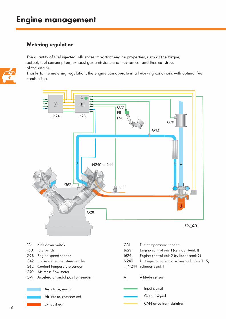
F8 Kick-down switchF60 Idle switchG28 Engine speed senderG42 Intake air temperature senderG62 Coolant temperature senderG70 Air-mass flow meterG79 Accelerator pedal position sender
J623J624
N240 … 244
G70
G28
G79F8F60
G62G81
G81 Fuel temperature senderJ623 Engine control unit 1 (cylinder bank 1)J624 Engine control unit 2 (cylinder bank 2)N240 Unit injector solenoid valves, cylinders 1 - 5, … N244 cylinder bank 1
A Altitude sensor
Metering regulation
The quantity of fuel injected influences important engine properties, such as the torque, output, fuel consumption, exhaust gas emissions and mechanical and thermal stress of the engine. Thanks to the metering regulation, the engine can operate in all working conditions with optimal fuel combustion.
304_079
G42
Air intake, normal
Air intake, compressed
Exhaust gas
Input signal
Output signal
CAN drive train databus
9
The parts systems illustrated as follows in this Self-Study Programme are based on the V10-TDI-engine as fitted in the Phaeton. As can already be seen in the illustrated overview, reference is made only to cylinder bank 1 for description of the systems. Likewise, only the components belonging to the relevant parts system are included in the key.
This is how it works:
The specified torque is calculated from the internal and external torque demands. To reach this torque specification, a set quantity of fuel is required.
The quantity of fuel, for example, is calculated by the engine control unit with respect to
– the driver's requirements,– the engine speed,– the amount of air drawn,– the coolant temperature,– the fuel temperature and – the intake air temperature.
However, to protect the engine against mechanical damage and to prevent black smoke, there should be limitations on the quantity of fuel injected. For this reason, the engine control unit calculates a limit value for this quantity.
The limit value depends on
– the engine speed,– the air mass and– the air pressure.
10
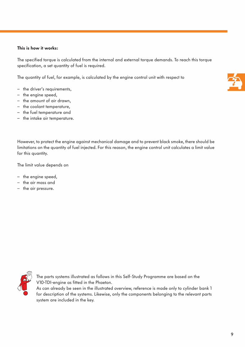
This is how it works:
The engine control unit calculates the start of injection.
The specification depends on
– the engine speed and– the calculated quantity of fuel to be injected
from the metering regulation.
A
t
I M
BIP
Further influencing factors are
– the coolant temperature and – the air pressure.
Engine management
304_073
G28 Engine speed senderG42 Intake air temperature senderG62 Coolant temperature senderJ623 Engine control unit 1 J624 Engine control unit 2 N240 Unit injector solenoid valves, cylinders 1 - 5 … N244
A Altitude sensor
N240 … 244
G62
G28
J623J624
Start of injection regulation
The start of injection regulation influences a number of engine properties, such as the engine performance, the fuel consumption, the noise emissions and, equally as important, the exhaust emissions. The start of injection regulation thus has the task of determining the correct point of fuel delivery and injection.
G42
Exhaust gas
Air intake, normal
Air intake, compressed
Input signal
Output signal
CAN drive train databus
11
t
I M
BIP
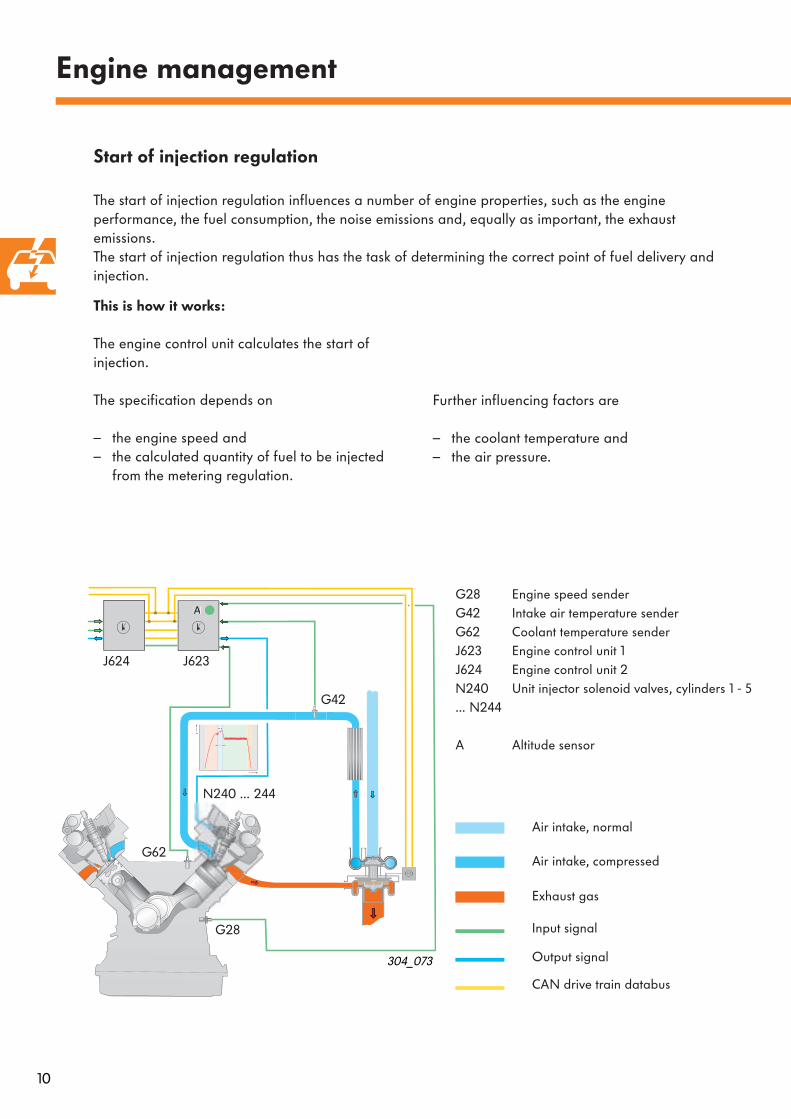
In order that the start of delivery can be calculated optimally, the actual point at which delivery begins must also be registered.
To do this, the engine control unit monitors the flow at the unit injector solenoid valve. From the special flow pattern, the actual start of delivery, and thereby the start of injection, is determined.
This is how it works:
Start of injection is initiated when the unit injector solenoid valve is actuated. For actuation, a magnetic field is created, current increases and the valve shuts. When the valve shuts on the valve seat, a distinctive jolt is noticeable in the current flow. This is known as COI (Commencement Of Injection period).COI signalises complete closure of the unit injector solenoid valve and thereby the point of delivery. The signal is received by the engine control unit.
If the valve is closed, current is maintained at a constant level. Once the required period of delivery has elapsed, actuation will cease and the valve will open.
The actual moment at which the unit injector solenoid valve closes, that is COI, is determined so that the point of actuation for the next injection period can be calculated.
If the actual COI deviates from the mapped details stored in the engine control unit, the engine control unit will correct the point of valve actuation.
In order that faults can be detected at the solenoid valve, the engine control unit evaluates the COI position from the current flow pattern. If there are no faults, COI will be within the control limit. If this is not the case, the valve is faulty.
Effects of signal loss
If faults are detected at the solenoid valve, start of delivery is determined based on fixed values from the map. Regulation is no longer possible and performance will be impaired.
I
M
– Solenoid valve currentt – TimeCOI (BIP) – Point at which valve shuts
304_072
Current pattern - Unit injector solenoid valve
Start of valve actuation
Pickup current
Holding current
End of valve actuation
Control limit
12
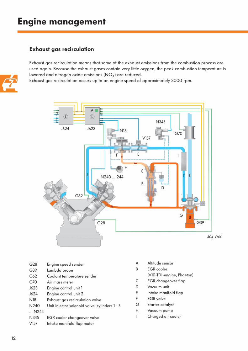
A Altitude sensorB EGR cooler
(V10-TDI-engine, Phaeton)C EGR changeover flapD Vacuum unitE Intake manifold flapF EGR valveG Starter catalystH Vacuum pumpI Charged air cooler
Engine management
Exhaust gas recirculation
Exhaust gas recirculation means that some of the exhaust emissions from the combustion process are used again. Because the exhaust gases contain very little oxygen, the peak combustion temperature is lowered and nitrogen oxide emissions (NO
X
) are reduced.Exhaust gas recirculation occurs up to an engine speed of approximately 3000 rpm.
G28 Engine speed senderG39 Lambda probeG62 Coolant temperature senderG70 Air mass meterJ623 Engine control unit 1J624 Engine control unit 2N18 Exhaust gas recirculation valveN240 Unit injector solenoid valve, cylinders 1 - 5… N244N345 EGR cooler changeover valveV157 Intake manifold flap motor
A
C
B
N18
N345
D
EF
N240 … 244
V157
G62
G28
G70
304_044
J624 J623
H
G39
G
I
13
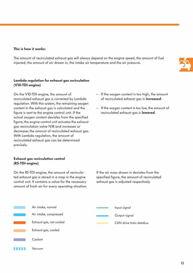
Exhaust gas recirculation control (R5-TDI-engine)
On the R5-TDI-engine, the amount of recircula-ted exhaust gas is stored in a map in the engine control unit. It contains a value for the necessary amount of fresh air for every operating situation.
Lambda regulation for exhaust gas recirculation(V10-TDI-engine)
On the V10-TDI-engine, the amount of recirculated exhaust gas is corrected by Lambda regulation. With this system, the remaining oxygen content in the exhaust gas is calculated and the figure is sent to the engine control unit. If the actual oxygen content deviates from the specified figure, the engine control unit actuates the exhaust gas recirculation valve N18 and increases or decreases the amount of recirculated exhaust gas.With Lambda regulation, the amount of recirculated exhaust gas can be determined precisely.
– If the oxygen content is too high, the amount of recirculated exhaust gas is
increased
.
– If the oxygen content is too low, the amount of recirculated exhaust gas is
lowered
.
If the air mass drawn in deviates from the specified figure, the amount of recirculated exhaust gas is adjusted respectively.
This is how it works:
The amount of recirculated exhaust gas will always depend on the engine speed, the amount of fuel injected, the amount of air drawn in, the intake air temperature and the air pressure.
Coolant
Vacuum
Exhaust gas, not cooled
Exhaust gas, cooled
Air intake, normal
Air intake, compressed
Input signal
Output signal
CAN drive train databus

14
Engine management
Without exhaust gas cooling
Up to a coolant temperature of 50
o
C, the exhaust gas flap remains closed and the exhaust gas is directed past the cooler.
With exhaust gas cooling
From a coolant temperature of 50
o
C, the exhaust gas flap is opened by the changeover valve. The recirculated exhaust gas will now flow past the cooler. The cooler output depends on the coolant temperature and the amount of recirculated exhaust gas.
Exhaust gas recirculation cooling
The V10-TDI-engine in the Phaeton has an independent cooler for exhaust gas recirculation for each cylinder bank due to its emissions classification. The system cools the recirculated exhaust gaswhen the coolant temperature exceeds 50
o
C.
This has two advantages:
– The combustion temperature is reduced and – A greater amount of exhaust gases can be recirculated.
This means that there is less nitrogen oxide and the build up of carbon is reduced.
This is how it works:
An independent exhaust gas recirculation cooler is used because continual cooling of the recirculated exhaust gas lengthens the period required for the engine to reach optimal operating temperature and leads to an increase in carbon dioxide and carbon monoxide emissions. For the independent cooling pro-cess, the exhaust gas is directed either past or through the cooler to the exhaust gas recirculation valve.
304_063 304_064
To exhaust gas recirculation valve
Exhaust gas flap
Cooler for exhaust gas recirculation To exhaust gas
turbocharger
Engine controlunit 1 J623
Vacuum unit, not actuated
Exhaust gas recirculation cooler changeover valve N345
Vacuum unit, actuated
From coolant temperature sender G62
From exhaustmanifold
15
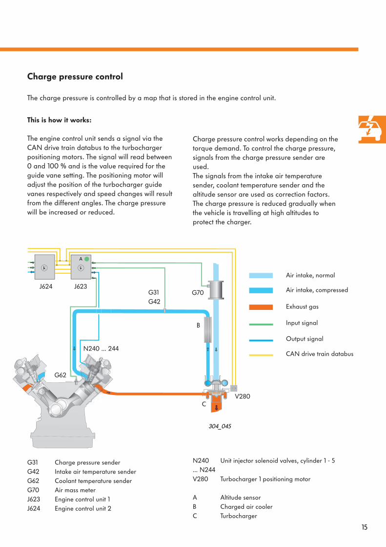
Charge pressure control works depending on the torque demand. To control the charge pressure, signals from the charge pressure sender are used.The signals from the intake air temperature sender, coolant temperature sender and the altitude sensor are used as correction factors.The charge pressure is reduced gradually when the vehicle is travelling at high altitudes to protect the charger.
This is how it works:
The engine control unit sends a signal via the CAN drive train databus to the turbocharger positioning motors. The signal will read between 0 and 100 % and is the value required for the guide vane setting. The positioning motor will adjust the position of the turbocharger guide vanes respectively and speed changes will result from the different angles. The charge pressure will be increased or reduced.
A
G31G42
J624 J623G70
C
304_045
G31 Charge pressure sender G42 Intake air temperature senderG62 Coolant temperature senderG70 Air mass meterJ623 Engine control unit 1J624 Engine control unit 2
N240 Unit injector solenoid valves, cylinder 1 - 5… N244V280 Turbocharger 1 positioning motor
A Altitude sensorB Charged air coolerC Turbocharger
B
N240 … 244
Charge pressure control
The charge pressure is controlled by a map that is stored in the engine control unit.
V280
G62
Exhaust gas
Air intake, normal
Air intake, compressed
Input signal
Output signal
CAN drive train databus
16
Engine management
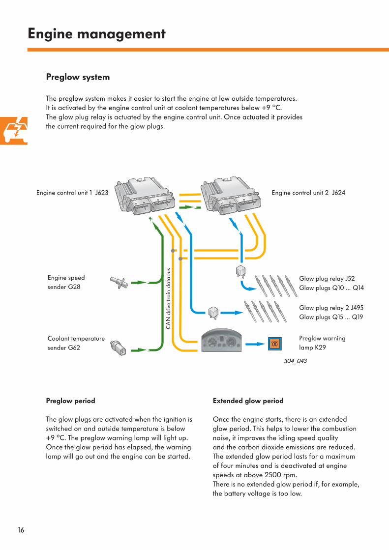
Preglow system
The preglow system makes it easier to start the engine at low outside temperatures. It is activated by the engine control unit at coolant temperatures below +9
o
C. The glow plug relay is actuated by the engine control unit. Once actuated it provides the current required for the glow plugs.
304_043
Extended glow period
Once the engine starts, there is an extended glow period. This helps to lower the combustion noise, it improves the idling speed quality and the carbon dioxide emissions are reduced. The extended glow period lasts for a maximum of four minutes and is deactivated at engine speeds at above 2500 rpm.There is no extended glow period if, for example, the battery voltage is too low.
Preglow period
The glow plugs are activated when the ignition is switched on and outside temperature is below +9
o
C. The preglow warning lamp will light up. Once the glow period has elapsed, the warning lamp will go out and the engine can be started.
Engine control unit 1 J623
Glow plug relay 2 J495Glow plugs Q15 … Q19
Engine control unit 2 J624
Glow plug relay J52Glow plugs Q10 … Q14
Engine speed sender G28
Preglow warning lamp K29
Coolant temperaturesender G62
CA
N d
rive
trai
n da
tabu
s
17
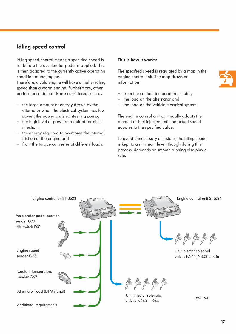
This is how it works:
The specified speed is regulated by a map in the engine control unit. The map draws on information
– from the coolant temperature sender,– the load on the alternator and– the load on the vehicle electrical system.
The engine control unit continually adapts the amount of fuel injected until the actual speed equates to the specified value.
To avoid unnecessary emissions, the idling speed is kept to a minimum level, though during this process, demands on smooth running also play a role.
Idling speed control
Idling speed control means a specified speed is set before the accelerator pedal is applied. This is then adapted to the currently active operating condition of the engine.Therefore, a cold engine will have a higher idling speed than a warm engine. Furthermore, other performance demands are considered such as
– the large amount of energy drawn by the alternator when the electrical system has low power, the power-assisted steering pump,
– the high level of pressure required for diesel injection,
– the energy required to overcome the internal friction of the engine and
– from the torque converter at different loads.
304_074
Accelerator pedal position sender G79Idle switch F60
Unit injector solenoid valves N240 … 244
Coolant temperaturesender G62
Additional requirements
Engine control unit 1 J623 Engine control unit 2 J624
Unit injector solenoid valves N245, N303 … 306
Engine speed sender G28
Alternator load (DFM signal)

18
Engine management
304_058
Example: Necessary changes in the amount of fuel injected at specified speeds of 580 rpm
Smooth running control
Smooth running control improves engine running at idling speed.
Different cylinders in an engine can often generate different levels of torque even though the same amount of fuel has been injected. Possible causes of this are, among other things, differences in
– the tolerances of the parts,– cylinder compressions,– friction caused by the cylinders and– the hydraulic injector components.
The effects of these differences in torque are
– imbalanced engine running and– an increase in exhaust gas emissions.
The smooth running control is designed to detect the pulses in speed that are caused as a result. The pulses in speed are then balanced by targeted control of the amount injected at the affected cylinders.
This is how it works:
Detection works at idling speed via a signal from the engine speed sender. If the signals are received in a balanced rhythm, the cylinders are all working the same way.If one cylinder performance is less than the others, the crankshaft needs longer to reach the next point of ignition.
And in the same way, a cylinder that performs better than the others will have a shorter path.If the engine control unit detects a deviation, the affected cylinder will receive a smaller or greater amount of fuel until the engine runs smoothly again.
Actual speed Change in quantity of fuel injected
19
12
20
25
800
1000
0 1 2
V (
mm
3 )
n (
1/m
in)
t (s)
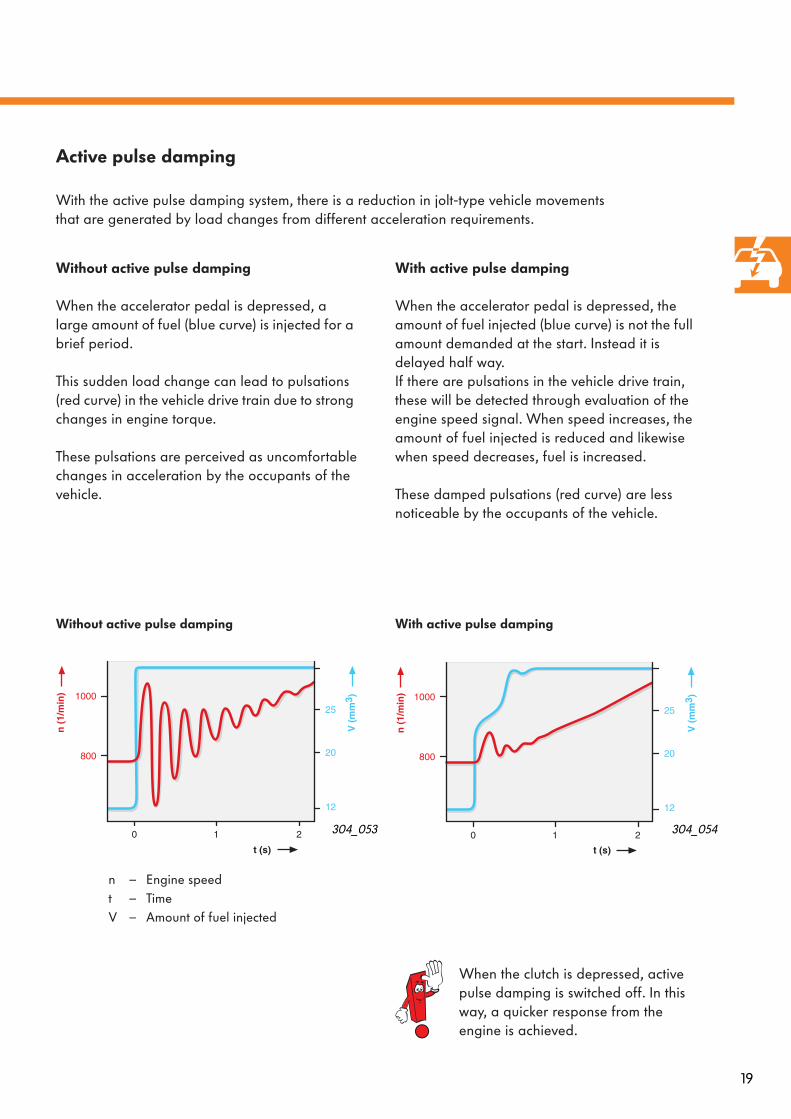
With active pulse damping
When the accelerator pedal is depressed, the amount of fuel injected (blue curve) is not the full amount demanded at the start. Instead it is delayed half way.If there are pulsations in the vehicle drive train, these will be detected through evaluation of the engine speed signal. When speed increases, the amount of fuel injected is reduced and likewise when speed decreases, fuel is increased.
These damped pulsations (red curve) are less noticeable by the occupants of the vehicle.
12
20
25
V (
mm
3 )
800
1000
n (
1/m
in)
0
t (s)
1 2
Without active pulse damping
When the accelerator pedal is depressed, a large amount of fuel (blue curve) is injected for a brief period.
This sudden load change can lead to pulsations (red curve) in the vehicle drive train due to strong changes in engine torque.
These pulsations are perceived as uncomfortablechanges in acceleration by the occupants of the vehicle.
304_054304_053
Without active pulse damping With active pulse damping
n – Engine speedt – TimeV – Amount of fuel injected
Active pulse damping
With the active pulse damping system, there is a reduction in jolt-type vehicle movements that are generated by load changes from different acceleration requirements.
When the clutch is depressed, active pulse damping is switched off. In this way, a quicker response from the engine is achieved.
20
1/m
in
t
Engine management
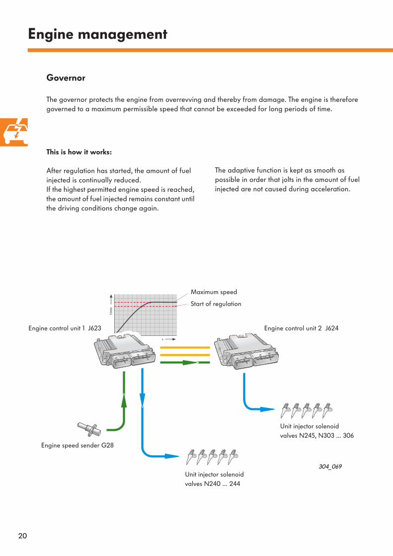
This is how it works:
After regulation has started, the amount of fuel injected is continually reduced. If the highest permitted engine speed is reached, the amount of fuel injected remains constant until the driving conditions change again.
The adaptive function is kept as smooth as possible in order that jolts in the amount of fuel injected are not caused during acceleration.
304_069
Governor
The governor protects the engine from overrevving and thereby from damage. The engine is therefore governed to a maximum permissible speed that cannot be exceeded for long periods of time.
Unit injector solenoid valves N240 … 244
Engine speed sender G28
Engine control unit 1 J623
Unit injector solenoid valves N245, N303 … 306
Maximum speed
Start of regulation
Engine control unit 2 J624
21
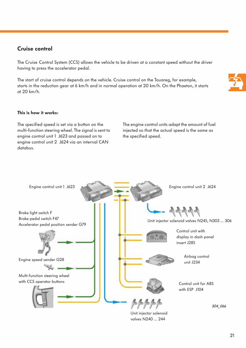
This is how it works:
The specified speed is set via a button on the multi-function steering wheel. The signal is sent to engine control unit 1 J623 and passed on to engine control unit 2 J624 via an internal CAN databus.
The engine control units adapt the amount of fuel injected so that the actual speed is the same as the specified speed.
304_066
Cruise control
The Cruise
Control System (CCS) allows the vehicle to be driven at a constant speed without the driver having to press the accelerator pedal.
The start of cruise control depends on the vehicle. Cruise control on the Touareg, for example, starts in the reduction gear at 6 km/h and in normal operation at 20 km/h. On the Phaeton, it starts at 20 km/h.
Engine control unit 1 J623
Engine speed sender G28
Brake light switch FBrake pedal switch F47Accelerator pedal position sender G79
Engine control unit 2 J624
Unit injector solenoid valves N240 … 244
Unit injector solenoid valves N245, N303 … 306
Control unit withdisplay in dash panelinsert J285
Multi-function steering wheel with CCS operator buttons
Airbag control unit J234
Control unit for ABS with ESP J104
22
Engine management
Sensors
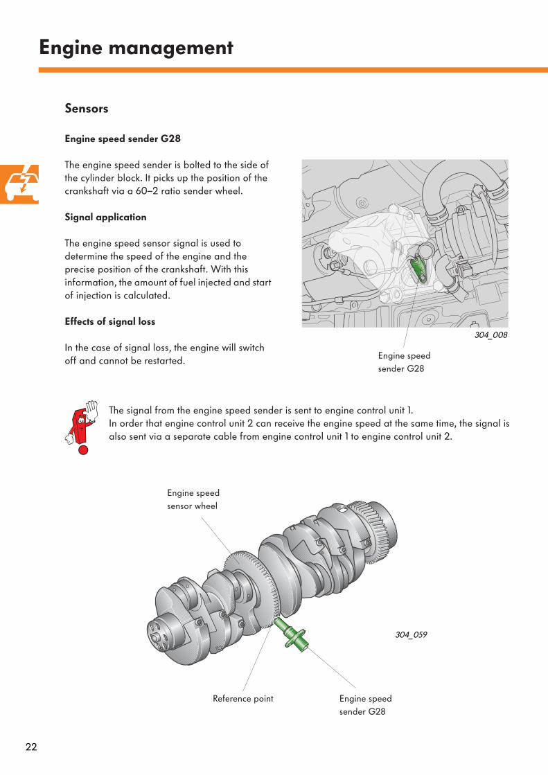
Engine speed sender G28
The engine speed sender is bolted to the side of the cylinder block. It picks up the position of the crankshaft via a 60–2 ratio sender wheel.
Signal application
The engine speed sensor signal is used to determine the speed of the engine and the precise position of the crankshaft. With this information, the amount of fuel injected and start of injection is calculated.
Effects of signal loss
In the case of signal loss, the engine will switch off and cannot be restarted.
304_008
Engine speed sender G28
The signal from the engine speed sender is sent to engine control unit 1. In order that engine control unit 2 can receive the engine speed at the same time, the signal is also sent via a separate cable from engine control unit 1 to engine control unit 2.
304_059
Engine speed sender G28
Engine speed sensor wheel
Reference point
23
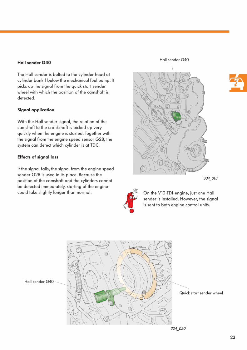
Hall sender G40
The Hall sender is bolted to the cylinder head at cylinder bank 1 below the mechanical fuel pump. It picks up the signal from the quick start sender wheel with which the position of the camshaft is detected.
Signal application
With the Hall sender signal, the relation of the camshaft to the crankshaft is picked up very quickly when the engine is started. Together with the signal from the engine speed sensor G28, the system can detect which cylinder is at TDC.
Effects of signal loss
If the signal fails, the signal from the engine speed sender G28 is used in its place. Because the position of the camshaft and the cylinders cannot be detected immediately, starting of the engine could take slightly longer than normal.
304_007
304_020
On the V10-TDI-engine, just one Hall sender is installed. However, the signal is sent to both engine control units.
Hall sender G40
Hall sender G40
Quick start sender wheel
24
Engine management
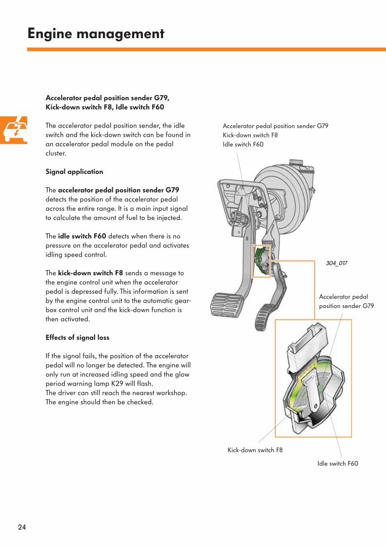
Accelerator pedal position sender G79,Kick-down switch F8, Idle switch F60
The accelerator pedal position sender, the idle switch and the kick-down switch can be found in an accelerator pedal module on the pedal cluster.
Signal application
The
accelerator pedal position sender G79
detects the position of the accelerator pedal across the entire range. It is a main input signal to calculate the amount of fuel to be injected.
The
idle switch F60
detects when there is no pressure on the accelerator pedal and activates idling speed control.
The
kick-down switch F8
sends a message to the engine control unit when the accelerator pedal is depressed fully. This information is sent by the engine control unit to the automatic gear-box control unit and the kick-down function is then activated.
Effects of signal loss
If the signal fails, the position of the accelerator pedal will no longer be detected. The engine will only run at increased idling speed and the glow period warning lamp K29 will flash. The driver can still reach the nearest workshop. The engine should then be checked.
304_017
Accelerator pedal position sender G79Kick-down switch F8 Idle switch F60
Idle switch F60
Kick-down switch F8
Accelerator pedal position sender G79
25
304_033
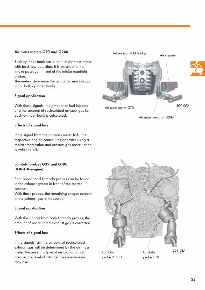
Air mass meters G70 and G246
Each cylinder bank has a hot film air mass meter with backflow detection. It is installed in the intake passage in front of the intake manifold bridge.The meters determine the actual air mass drawn in for both cylinder banks.
Signal application
With these signals, the amount of fuel injected and the amount of recirculated exhaust gas for each cylinder bank is calculated.
Effects of signal loss
If the signal from the air mass meter fails, the respective engine control unit operates using a replacement value and exhaust gas recirculation is switched off.
Lambda probes G39 and G108 (V10-TDI-engine)
Both broadband Lambda probes can be found in the exhaust system in front of the starter catalyst. With these probes, the remaining oxygen content in the exhaust gas is measured.
Signal application
With the signals from both Lambda probes, the amount of recirculated exhaust gas is corrected.
Effects of signal loss
If the signals fail, the amount of recirculated exhaust gas will be determined by the air mass meter. Because this type of regulation is not precise, the level of nitrogen oxide emissions may rise.
304_060
Air mass meter G70
Air mass meter 2 G246
Lambdaprobe G39
Lambdaprobe 2 G108
Air cleanerIntake manifold bridge

26
Engine management
304_034
304_035
Coolant temperature sender G62
The coolant temperature sender can be found in the coolant connecting pipe between the cylinder heads. It sends the coolant temperature to engine control unit 1 J623.
Signal application
The coolant temperature is used by the engine control units as a correction value to calculate the amount of fuel to be injected, the charge pressure, start of delivery and the amount of recirculated exhaust gas, for example. In addi-tion, this information is used to regulate the coo-lant temperature depending on the operating conditions.
Effects of signal loss
If the signal fails, the engine control units use the signals from the coolant temperature sender G83 and the fuel temperature senders G81 and G248.
Coolant temperature sender - radiator outlet G83
The coolant temperature sender G83 can be found in the line at the radiator outlet and it is from this position that the coolant temperature is measured.
Signal application
By comparing both signals from coolant tempe-rature senders G62 and G83, the radiator fans can be actuated.
Effects of signal loss
If the signal from coolant temperaturesender G83 fails, radiator fan output stage 1 remains constantly active. Coolant temperature regulation is continued.
Coolant temperaturesender G62
Coolant temperature sender - radiator outlet G83
Coolant connecting pipe
27
304_006
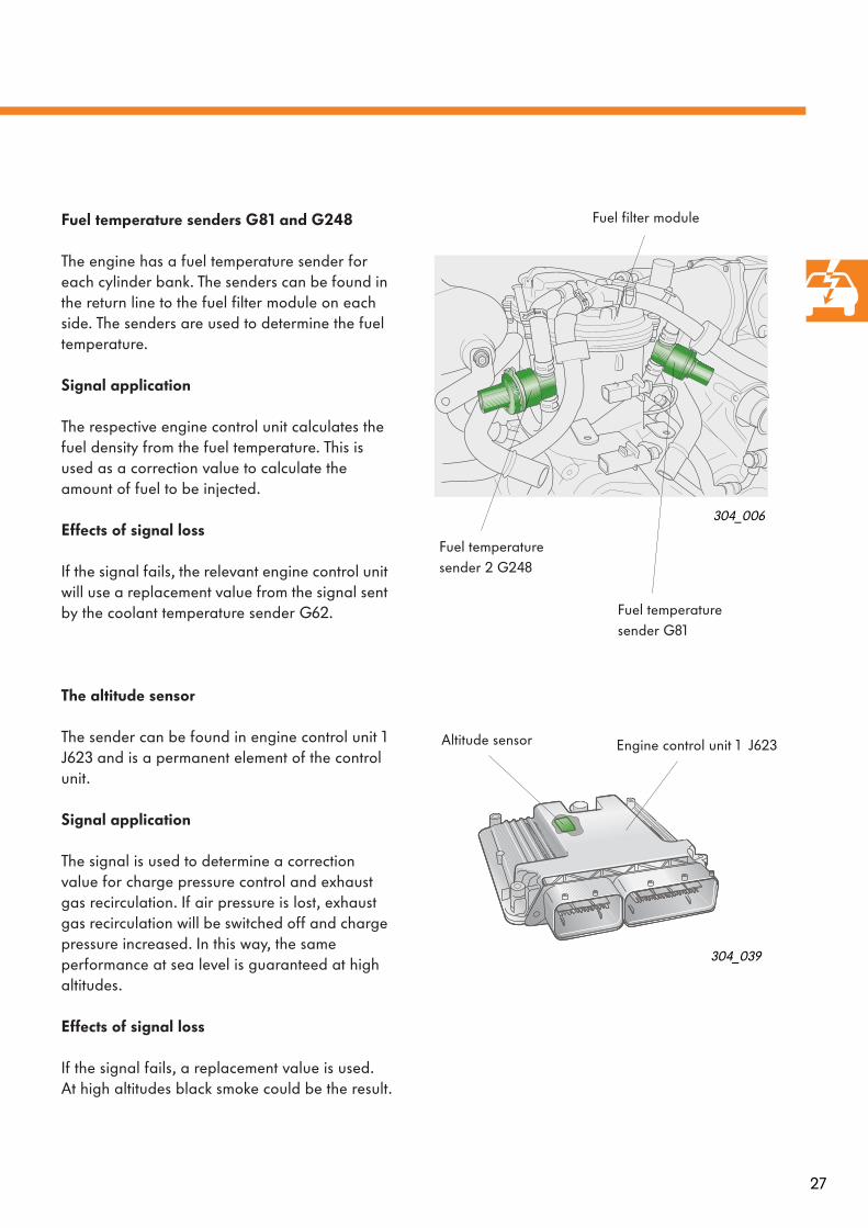
Fuel temperature senders G81 and G248
The engine has a fuel temperature sender for each cylinder bank. The senders can be found in the return line to the fuel filter module on each side. The senders are used to determine the fuel temperature.
Signal application
The respective engine control unit calculates the fuel density from the fuel temperature. This is used as a correction value to calculate the amount of fuel to be injected.
Effects of signal loss
If the signal fails, the relevant engine control unit will use a replacement value from the signal sent by the coolant temperature sender G62.
The altitude sensor
The sender can be found in engine control unit 1 J623 and is a permanent element of the control unit.
Signal application
The signal is used to determine a correction value for charge pressure control and exhaust gas recirculation. If air pressure is lost, exhaust gas recirculation will be switched off and charge pressure increased. In this way, the same performance at sea level is guaranteed at high altitudes.
Effects of signal loss
If the signal fails, a replacement value is used. At high altitudes black smoke could be the result.
304_039
Fuel temperature sender 2 G248
Fuel temperature sender G81
Fuel filter module
Altitude sensor Engine control unit 1 J623
28
Engine management
Intake air temperature senders G42 and G299
Signal application
The signal from the intake air temperature senders is required by the engine control units to calculate a correction value for the charge pressure. When the signal from these senders is evaluated, the influence of the temperature on the density of the fuel is also considered.
Effects of signal loss
If a signal fails, the engine control units will use a fixed replacement value. The result could be impaired performance.
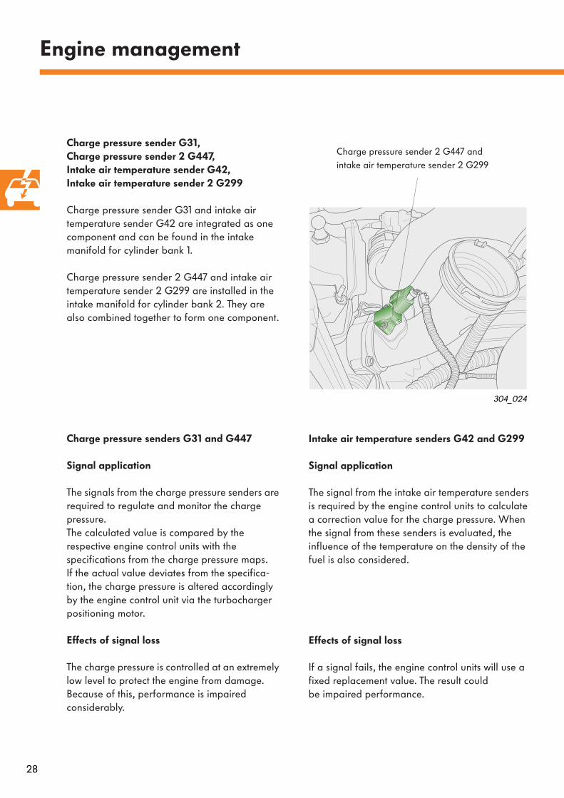
Charge pressure sender G31, Charge pressure sender 2 G447,Intake air temperature sender G42, Intake air temperature sender 2 G299
Charge pressure sender G31 and intake air temperature sender G42 are integrated as one component and can be found in the intake manifold for cylinder bank 1.
Charge pressure sender 2 G447 and intake air temperature sender 2 G299 are installed in the intake manifold for cylinder bank 2. They are also combined together to form one component.
Charge pressure senders G31 and G447
Signal application
The signals from the charge pressure senders are required to regulate and monitor the charge pressure. The calculated value is compared by the respective engine control units with the specifications from the charge pressure maps. If the actual value deviates from the specifica-tion, the charge pressure is altered accordingly by the engine control unit via the turbocharger positioning motor.
Effects of signal loss
The charge pressure is controlled at an extremely low level to protect the engine from damage. Because of this, performance is impaired considerably.
Charge pressure sender 2 G447 andintake air temperature sender 2 G299
304_024

29
Brake light switch F and Brake pedalswitch F47
The brake light switch and the brake pedal switch are part of one component and can be found on the pedal cluster. Both switches send a signal to engine control unit 1 when the brake is applied.
Signal application
When the brake is applied, the cruise control system is switched off.If actuation of the accelerator pedal and the brake pedal is detected, idling speed is increased.
Effects of signal loss
If the signal fails from one of the senders, the amount of fuel injected will be reduced and the engine will have less output.In addition, the cruise control system will be switched off.
Clutch pedal switch F36 (manual gearbox)
The clutch pedal switch can be found on the pedal cluster. The switch detects whether the clutch is depressed or not.
Signal application
When the clutch is depressed, the amount of fuel injected is reduced for a brief period to prevent engine jolts during gear selection.
Effects of signal loss
If signal failure is encountered from the clutch pedal switch, load jolts could become noticeable from gear changes.The cruise control system and active pulse damping are no longer available.
304_081
Clutch pedal switch F36
Brake pedal switch F and brake pedal switch F47
30
Signal application
The signal from the sender prevents water from entering the injection system and thereby prevents corrosion.
Engine management
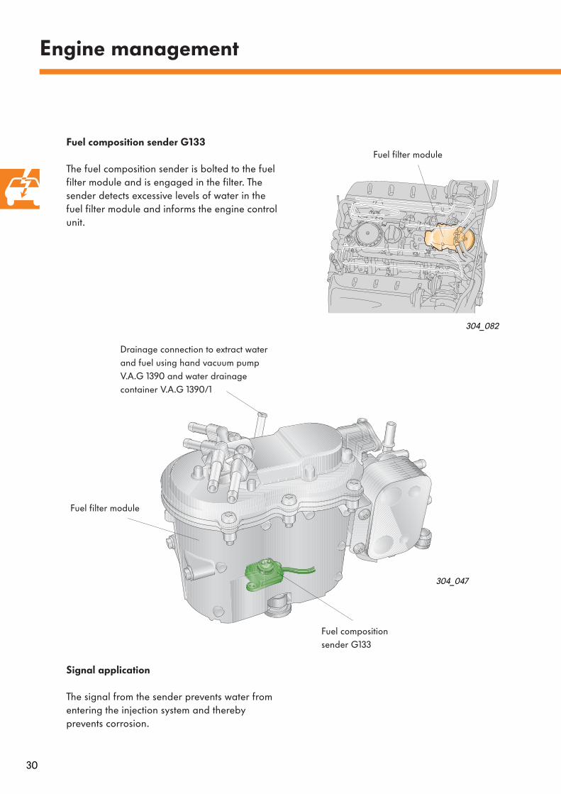
Fuel composition sender G133
The fuel composition sender is bolted to the fuel filter module and is engaged in the filter. The sender detects excessive levels of water in the fuel filter module and informs the engine control unit.
304_047
Drainage connection to extract water and fuel using hand vacuum pump V.A.G 1390 and water drainage container V.A.G 1390/1
Fuel compositionsender G133
304_082
Fuel filter module
Fuel filter module
31
450
V
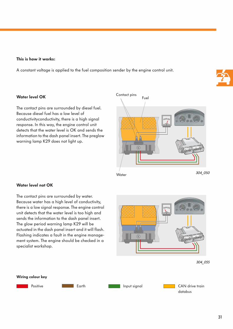
This is how it works:
A constant voltage is applied to the fuel composition sender by the engine control unit.
Water level OK
The contact pins are surrounded by diesel fuel. Because diesel fuel has a low level of conductivityconductivity, there is a high signal response. In this way, the engine control unit detects that the water level is OK and sends the information to the dash panel insert. The preglow warning lamp K29 does not light up.
Water level not OK
The contact pins are surrounded by water. Because water has a high level of conductivity, there is a low signal response. The engine control unit detects that the water level is too high and sends the information to the dash panel insert. The glow period warning lamp K29 will be actuated in the dash panel insert and it will flash. Flashing indicates a fault in the engine manage-ment system. The engine should be checked in a specialist workshop.
304_050
304_055
450
V
Water
Input signal CAN drive train databus
EarthPositive
Fuel
Wiring colour key
Contact pins
32
Actuators
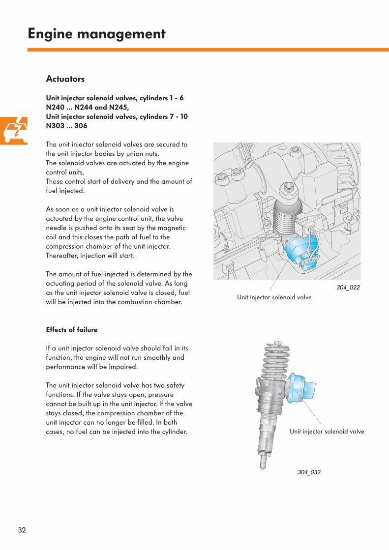
Unit injector solenoid valves, cylinders 1 - 6 N240 … N244 and N245, Unit injector solenoid valves, cylinders 7 - 10 N303 … 306
The unit injector solenoid valves are secured to the unit injector bodies by union nuts. The solenoid valves are actuated by the engine control units. These control start of delivery and the amount of fuel injected.
As soon as a unit injector solenoid valve is actuated by the engine control unit, the valve needle is pushed onto its seat by the magnetic coil and this closes the path of fuel to the compression chamber of the unit injector. Thereafter, injection will start.
The amount of fuel injected is determined by the actuating period of the solenoid valve. As long as the unit injector solenoid valve is closed, fuel will be injected into the combustion chamber.
Effects of failure
If a unit injector solenoid valve should fail in its function, the engine will not run smoothly and performance will be impaired.
The unit injector solenoid valve has two safety functions. If the valve stays open, pressure cannot be built up in the unit injector. If the valve stays closed, the compression chamber of the unit injector can no longer be filled. In both cases, no fuel can be injected into the cylinder.
Engine management
304_022
304_032
Unit injector solenoid valve
Unit injector solenoid valve
33
304_010
304_078
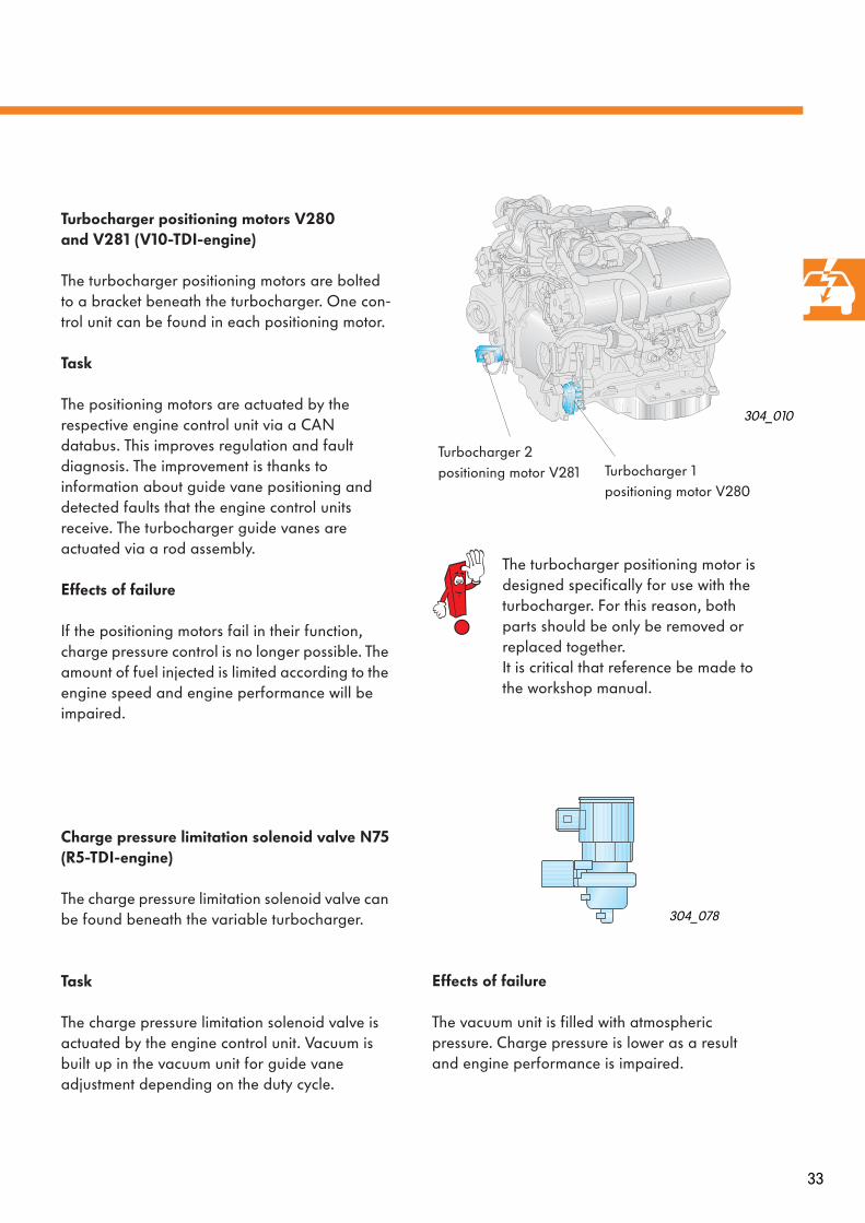
Turbocharger positioning motors V280 and V281 (V10-TDI-engine)
The turbocharger positioning motors are bolted to a bracket beneath the turbocharger. One con-trol unit can be found in each positioning motor.
Task
The positioning motors are actuated by the respective engine control unit via a CAN databus. This improves regulation and fault diagnosis. The improvement is thanks to information about guide vane positioning and detected faults that the engine control units receive. The turbocharger guide vanes are actuated via a rod assembly.
Effects of failure
If the positioning motors fail in their function, charge pressure control is no longer possible. The amount of fuel injected is limited according to the engine speed and engine performance will be impaired.
Charge pressure limitation solenoid valve N75(R5-TDI-engine)
The charge pressure limitation solenoid valve can be found beneath the variable turbocharger.
Task
The charge pressure limitation solenoid valve is actuated by the engine control unit. Vacuum is built up in the vacuum unit for guide vane adjustment depending on the duty cycle.
Turbocharger 1 positioning motor V280
Turbocharger 2 positioning motor V281
Effects of failure
The vacuum unit is filled with atmospheric pressure. Charge pressure is lower as a result and engine performance is impaired.
The turbocharger positioning motor is designed specifically for use with the turbocharger. For this reason, both parts should be only be removed or replaced together.It is critical that reference be made to the workshop manual.

34
Engine management
Exhaust gas recirculation solenoid valves N18 and N213
The solenoid valves for exhaust gas recirculation can be found on the suspension strut domes on each side. The valves are electro-pneumatic.
Task
The valves are actuated with a duty cycle by the engine control unit depending on the map. In this way, the control pressure for the recirculation valve can be set. The cross section of the exhaust manifold is changed in the exhaust gas recirculation valve depending on the control pressure and the amount of recirculated exhaust gas set.
Effects of failure
If the signal fails, exhaust gas recirculation may no longer be possible.
Intake manifold flap motors V157 and V275
The V10-TDI-engine has two electrically adjustable intake manifold flaps and there is one electric motor for each flap. These can be found directly in front of the respective exhaust gas recirculation valve.
Task
– With the electrically adjustable intake manifold flaps, differences between air intake pressure and exhaust gas pressure are generated in certain operating conditions. Effective exhaust gas recirculation is guaranteed thanks to the differences in pressure.
– When the engine is switched off, the flap is closed and the flow of air interrupted. In this way, less air is drawn in and compressed which helps smooth run-down of the engine.
304_012
Effects of failure
In case of failure, effective exhaust gas recirculation is no longer possible.
304_011
Exhaust gasrecirculation valve N18
Exhaust gasrecirculation valve 2 N213
Intake manifold flap motor V157
Intake manifold flap motor 2 V275
Exhaust gasrecirculation valve
35
304_048
304_048
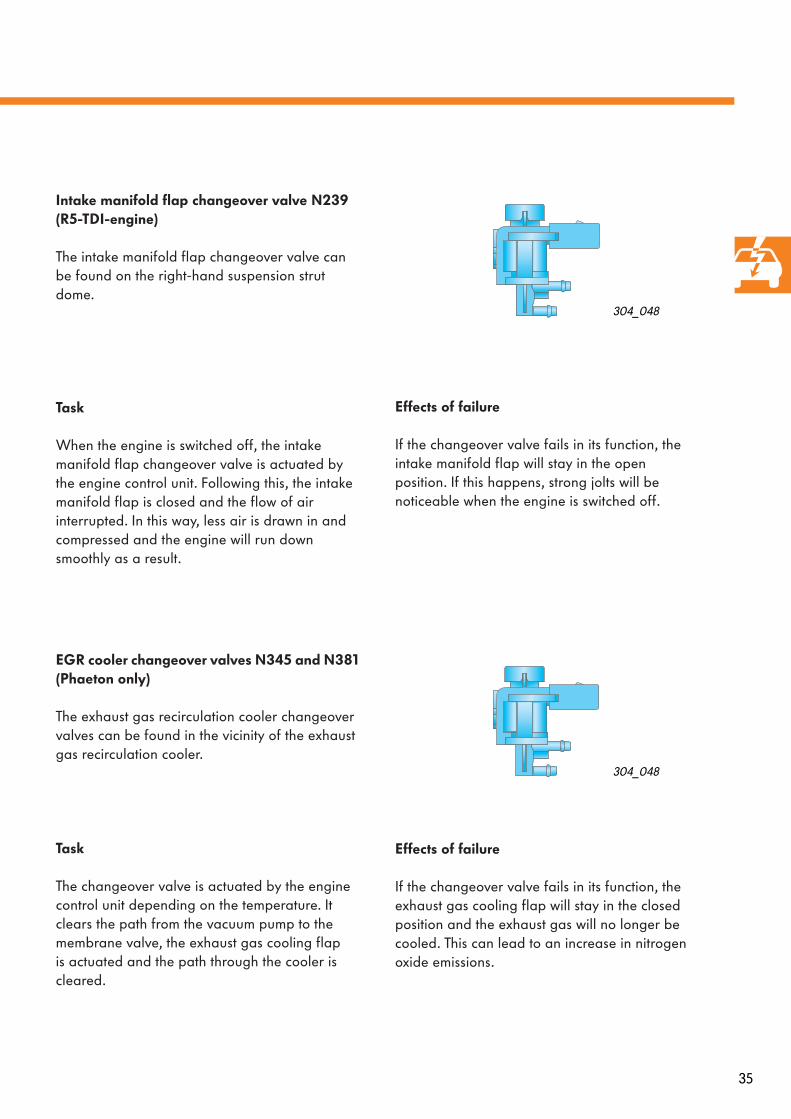
Effects of failure
If the changeover valve fails in its function, the intake manifold flap will stay in the open position. If this happens, strong jolts will be noticeable when the engine is switched off.
Effects of failure
If the changeover valve fails in its function, the exhaust gas cooling flap will stay in the closed position and the exhaust gas will no longer be cooled. This can lead to an increase in nitrogen oxide emissions.
Intake manifold flap changeover valve N239(R5-TDI-engine)
The intake manifold flap changeover valve can be found on the right-hand suspension strut dome.
Task
When the engine is switched off, the intake manifold flap changeover valve is actuated by the engine control unit. Following this, the intake manifold flap is closed and the flow of air interrupted. In this way, less air is drawn in and compressed and the engine will run down smoothly as a result.
EGR cooler changeover valves N345 and N381 (Phaeton only)
The exhaust gas recirculation cooler changeover valves can be found in the vicinity of the exhaust gas recirculation cooler.
Task
The changeover valve is actuated by the engine control unit depending on the temperature. It clears the path from the vacuum pump to the membrane valve, the exhaust gas cooling flap is actuated and the path through the cooler is cleared.

36
Engine management
Exhaust gas recirculation cooler (Phaeton only)
The V10-TDI-engine in the Phaeton is equipped with independent coolers for the exhaust gas recirculation system.
The pneumatically controlled flaps for exhaust gas cooling allow activation of the cooler from a coolant temperature of 50
o
C.
304_014
304_031
Cooler for exhaust gas recirculation
Vacuum unit
Cooler for exhaust gas recirculationTo valve
for exhaust gas recirculation
From exhaust manifold
From exhaust manifold
Coolant connection Coolant distribution to switch unit with flap for exhaust gas cooling
37
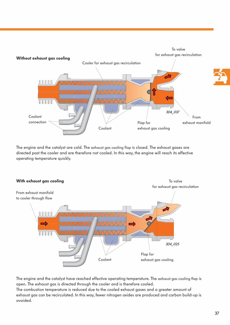
Without exhaust gas cooling
304_025
304_037
With exhaust gas cooling
The engine and the catalyst are cold. The
exhaust gas cooling flap
is closed. The exhaust gases are directed past the cooler and are therefore not cooled. In this way, the engine will reach its effective operating temperature quickly.
The engine and the catalyst have reached effective operating temperature. The
exhaust gas cooling flap
is open. The exhaust gas is directed through the cooler and is therefore cooled. The combustion temperature is reduced due to the cooled exhaust gases and a greater amount of exhaust gas can be recirculated. In this way, fewer nitrogen oxides are produced and carbon build-up is avoided.
Cooler for exhaust gas recirculation
To valvefor exhaust gas recirculation
Coolant
Coolantconnection Flap for
exhaust gas cooling
From exhaust manifold
From exhaust manifold to cooler through flow
To valvefor exhaust gas recirculation
Flap for exhaust gas coolingCoolant

38
Engine management
– Fuel pump G23 with fuel gauge sender G and a suction jet pump can be found in the main chamber of the fuel tank.
– Fuel pump G6 with fuel gauge sender 3 G237 and a suction jet pump can be found in the secondary chamber of the fuel tank.
304_049
Actuation of both electrical fuel pumps is done in parallel sequence via the fuel pump relay J17.
Suction jet pump 1 draws fuel from the main chamber into the presupply reservoir of fuel pump G6 and suction jet pump 2 pumps out the secondary chamber into the presupply reservoir of fuel pump G23. Both suction jet pumps are driven by the electrical fuel pumps.
Effects of failure
If one pump fails, engine performance will be impaired due to a restriction in the amount of fuel supplied.
The maximum speed is unattainable and the engine will not run smoothly at high revs.
Fuel pumps G6 and G23
Both electrical fuel pumps are installed in the fuel tank.
Fuel pump G6(presupply pump)
Fuel pump G23
Suction jet pump 2Suction jet pump 1
Fuel gauge sender 3 G237
Fuel gauge sender G
39
304_016
304_029
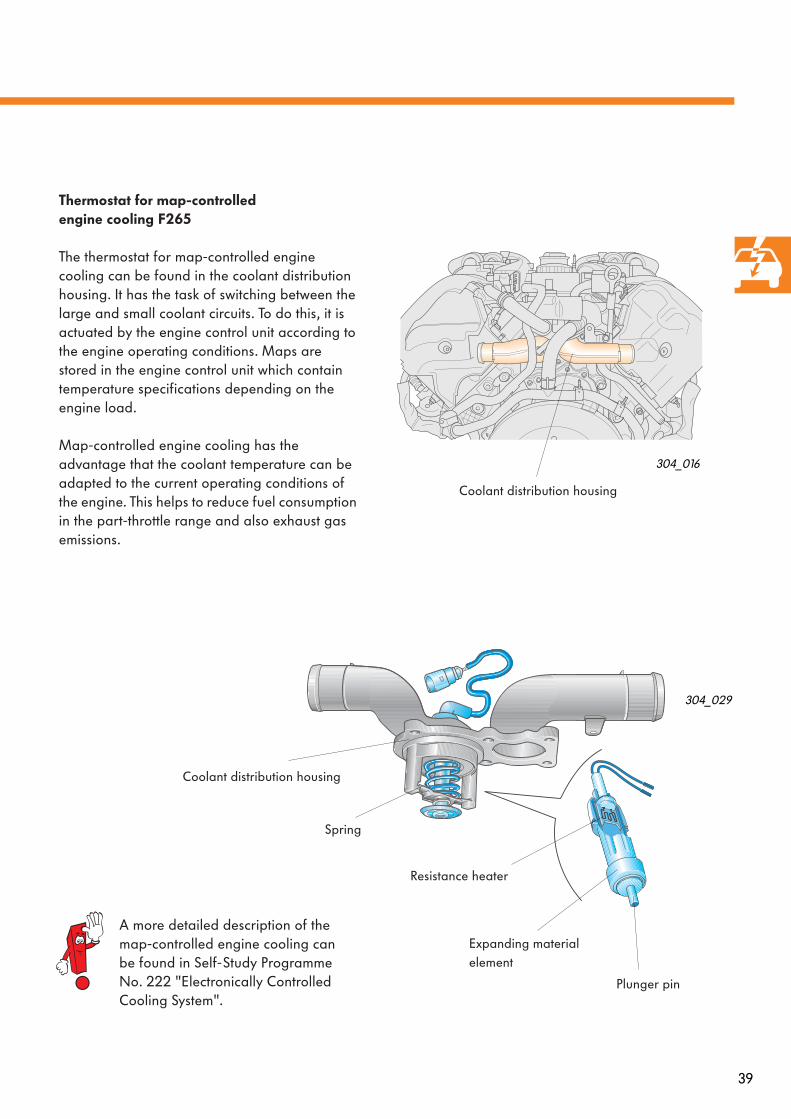
A more detailed description of the map-controlled engine cooling can be found in Self-Study Programme No. 222 "Electronically Controlled Cooling System".
Thermostat for map-controlledengine cooling F265
The thermostat for map-controlled engine cooling can be found in the coolant distribution housing. It has the task of switching between the large and small coolant circuits. To do this, it is actuated by the engine control unit according to the engine operating conditions. Maps are stored in the engine control unit which contain temperature specifications depending on the engine load.
Map-controlled engine cooling has the advantage that the coolant temperature can be adapted to the current operating conditions of the engine. This helps to reduce fuel consumption in the part-throttle range and also exhaust gas emissions.
Expanding material element
Plunger pin
Spring
Resistance heater
Coolant distribution housing
Coolant distribution housing
40
Engine management
J623
M
J496
V51
304_027
304_067
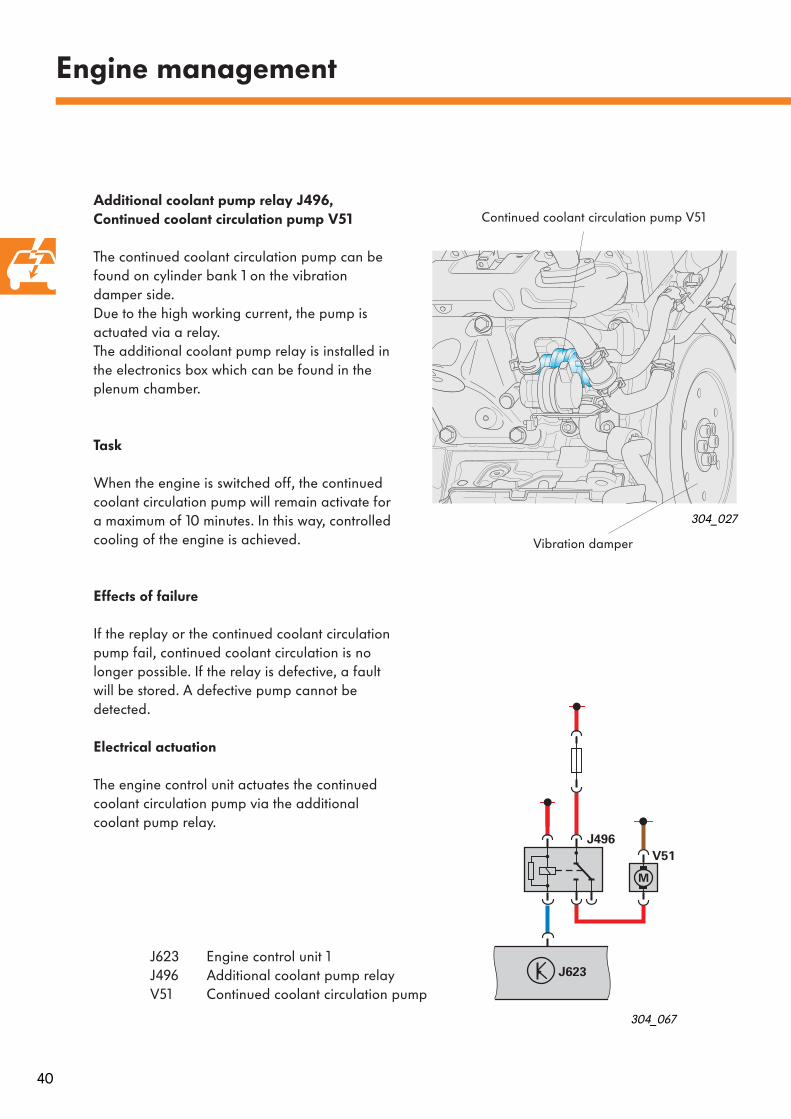
J623 Engine control unit 1J496 Additional coolant pump relayV51 Continued coolant circulation pump
Additional coolant pump relay J496, Continued coolant circulation pump V51
The continued coolant circulation pump can be found on cylinder bank 1 on the vibrationdamper side. Due to the high working current, the pump is actuated via a relay.The additional coolant pump relay is installed in the electronics box which can be found in the plenum chamber.
Task
When the engine is switched off, the continued coolant circulation pump will remain activate for a maximum of 10 minutes. In this way, controlled cooling of the engine is achieved.
Effects of failure
If the replay or the continued coolant circulation pump fail, continued coolant circulation is no longer possible. If the relay is defective, a fault will be stored. A defective pump cannot be detected.
Electrical actuation
The engine control unit actuates the continued coolant circulation pump via the additional coolant pump relay.
Continued coolant circulation pump V51
Vibration damper
41
J623
M
J445
V166
304_009
304_068
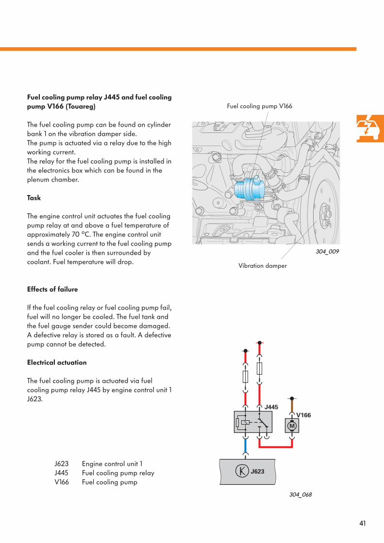
Fuel cooling pump relay J445 and fuel cooling pump V166 (Touareg)
The fuel cooling pump can be found on cylinder bank 1 on the vibration damper side.The pump is actuated via a relay due to the high working current.The relay for the fuel cooling pump is installed in the electronics box which can be found in the plenum chamber.
Task
The engine control unit actuates the fuel cooling pump relay at and above a fuel temperature of approximately 70
o
C. The engine control unit sends a working current to the fuel cooling pump and the fuel cooler is then surrounded by coolant. Fuel temperature will drop.
Effects of failure
If the fuel cooling relay or fuel cooling pump fail, fuel will no longer be cooled. The fuel tank and the fuel gauge sender could become damaged.A defective relay is stored as a fault. A defective pump cannot be detected.
Electrical actuation
The fuel cooling pump is actuated via fuel cooling pump relay J445 by engine control unit 1 J623.
Fuel cooling pump V166
Vibration damper
J623 Engine control unit 1J445 Fuel cooling pump relayV166 Fuel cooling pump

42
Engine management
Right solenoid valve for electro-hydraulic engine mounting N145 (Phaeton)
The V10-TDI-engine in the Phaeton features hydraulically dampening engine mountings.
These engine mountings reduce the transmission of engine vibration to the body and in doing so provide a high level of driving comfort.
304_041
304_040
Left engine mounting
Engine carrier
Right engine mounting
Left engine bracket
Right engine bracket
Right solenoid valve for electro-hydraulic engine mounting N145
43
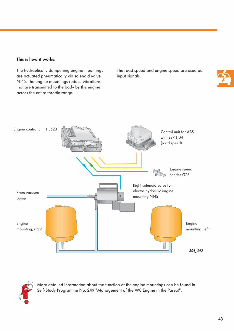
This is how it works:
The hydraulically dampening engine mountings are actuated pneumatically via solenoid valve N145. The engine mountings reduce vibrations that are transmitted to the body by the engine across the entire throttle range.
The road speed and engine speed are used as input signals.
304_042
More detailed information about the function of the engine mountings can be found in Self-Study Programme No. 249 "Management of the W8 Engine in the Passat".
Control unit for ABS with ESP J104 (road speed)
Engine speed sender G28
Right solenoid valve for electro-hydraulic engine mounting N145
Engine mounting, right
Engine mounting, left
Engine control unit 1 J623
From vacuum pump

44 45
M M M
N213
C
N381
J623
30
15
6 7 8 9
J624
N240 N241 N242 N243 N244 N245 N303 N304 N305 N306G81 G248 G447 G299
43 1 2
J317
J689
λ
G108 Z28
λ
G39 Z19
MH
V275
B
M
V157
M
V280 V281
N18
C
F265
M
E F
M
J496
V51
J445
V166
G62 G83 G133
+
G40G31 G42
F
G28 F60/F8 G79
J17
A
G23
N145
H
B
G
G70
30
15
FF47
C
J495
D
A
J52
55
E
Q10...Q14 Q15...Q19
1
2
N345
D
G6
G246
G
Engine management
Additional signal
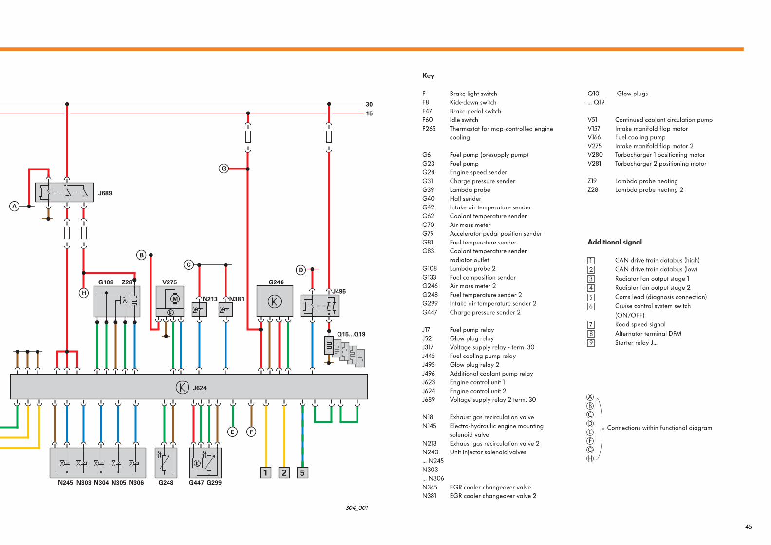
CAN drive train databus (high)CAN drive train databus (low)Radiator fan output stage 1Radiator fan output stage 2Coms lead (diagnosis connection)Cruise control system switch (ON/OFF)Road speed signalAlternator terminal DFMStarter relay J...
Key
F Brake light switch F8 Kick-down switch F47 Brake pedal switch F60 Idle switch F265 Thermostat for map-controlled engine
cooling
G6 Fuel pump (presupply pump)G23 Fuel pumpG28 Engine speed sender G31 Charge pressure senderG39 Lambda probeG40 Hall sender G42 Intake air temperature sender G62 Coolant temperature senderG70 Air mass meterG79 Accelerator pedal position senderG81 Fuel temperature senderG83 Coolant temperature sender
radiator outletG108 Lambda probe 2G133 Fuel composition senderG246 Air mass meter 2G248 Fuel temperature sender 2G299 Intake air temperature sender 2G447 Charge pressure sender 2
J17 Fuel pump relayJ52 Glow plug relayJ317 Voltage supply relay - term. 30J445 Fuel cooling pump relayJ495 Glow plug relay 2J496 Additional coolant pump relay J623 Engine control unit 1J624 Engine control unit 2J689 Voltage supply relay 2 term. 30
N18 Exhaust gas recirculation valve N145 Electro-hydraulic engine mounting
solenoid valve N213 Exhaust gas recirculation valve 2 N240 Unit injector solenoid valves ... N245 N303 ... N306 N345 EGR cooler changeover valveN381 EGR cooler changeover valve 2
Q10 Glow plugs... Q19
V51 Continued coolant circulation pump V157 Intake manifold flap motor V166 Fuel cooling pump V275 Intake manifold flap motor 2 V280 Turbocharger 1 positioning motor V281 Turbocharger 2 positioning motor
Z19 Lambda probe heating Z28 Lambda probe heating 2
123456
789
ABCD
Connections within functional diagramEFGH
Functional diagram for V10-TDI-engine
304_001
44 45
M M M
N213
C
N381
J623
30
15
6 7 8 9
J624
N240 N241 N242 N243 N244 N245 N303 N304 N305 N306G81 G248 G447 G299
43 1 2
J317
J689
λ
G108 Z28
λ
G39 Z19
MH
V275
B
M
V157
M
V280 V281
N18
C
F265
M
E F
M
J496
V51
J445
V166
G62 G83 G133
+
G40G31 G42
F
G28 F60/F8 G79
J17
A
G23
N145
H
B
G
G70
30
15
FF47
C
J495
D
A
J52
55
E
Q10...Q14 Q15...Q19
1
2
N345
D
G6
G246
G
Engine management
Additional signal
CAN drive train databus (high)CAN drive train databus (low)Radiator fan output stage 1Radiator fan output stage 2Coms lead (diagnosis connection)Cruise control system switch (ON/OFF)Road speed signalAlternator terminal DFMStarter relay J...
Key
F Brake light switch F8 Kick-down switch F47 Brake pedal switch F60 Idle switch F265 Thermostat for map-controlled engine
cooling
G6 Fuel pump (presupply pump)G23 Fuel pumpG28 Engine speed sender G31 Charge pressure senderG39 Lambda probeG40 Hall sender G42 Intake air temperature sender G62 Coolant temperature senderG70 Air mass meterG79 Accelerator pedal position senderG81 Fuel temperature senderG83 Coolant temperature sender
radiator outletG108 Lambda probe 2G133 Fuel composition senderG246 Air mass meter 2G248 Fuel temperature sender 2G299 Intake air temperature sender 2G447 Charge pressure sender 2
J17 Fuel pump relayJ52 Glow plug relayJ317 Voltage supply relay - term. 30J445 Fuel cooling pump relayJ495 Glow plug relay 2J496 Additional coolant pump relay J623 Engine control unit 1J624 Engine control unit 2J689 Voltage supply relay 2 term. 30
N18 Exhaust gas recirculation valve N145 Electro-hydraulic engine mounting
solenoid valve N213 Exhaust gas recirculation valve 2 N240 Unit injector solenoid valves ... N245 N303 ... N306 N345 EGR cooler changeover valveN381 EGR cooler changeover valve 2
Q10 Glow plugs... Q19
V51 Continued coolant circulation pump V157 Intake manifold flap motor V166 Fuel cooling pump V275 Intake manifold flap motor 2 V280 Turbocharger 1 positioning motor V281 Turbocharger 2 positioning motor
Z19 Lambda probe heating Z28 Lambda probe heating 2
123456
789
ABCD
Connections within functional diagramEFGH
Functional diagram for V10-TDI-engine
304_001

46
Self-diagnosis
Diagnosis
On vehicle diagnosis, testing and information systems VAS 5051 and VAS 5052:
– Guided fault finding
*
and– Vehicle self-diagnosis
can be selected.
Operating mode "Guided fault finding"
checks all vehicle-specific control units for stored faults and automatically compiles an individual testing plan based on the results.This plan is carried out in conjunction with ELSA information, such as current flow diagrams or workshop manuals, selected to aid fault finding.
In addition to this, you can also compile your own testing plan. The tests you choose from the selection of functions and components will be added to the testing plan and can be carried out as a diagnostic sequence in any order.
Operating mode "Vehicle Self-Diagnosis"
can be used in the same way as normal but no additional information is available from ELSA.
Service
304_051
304_052
* Not with vehicle diagnosis and
service information system VAS 5052
More detailed information about guided fault finding can be found in chapter 7 of the VAS 5051 operating handbook.
47
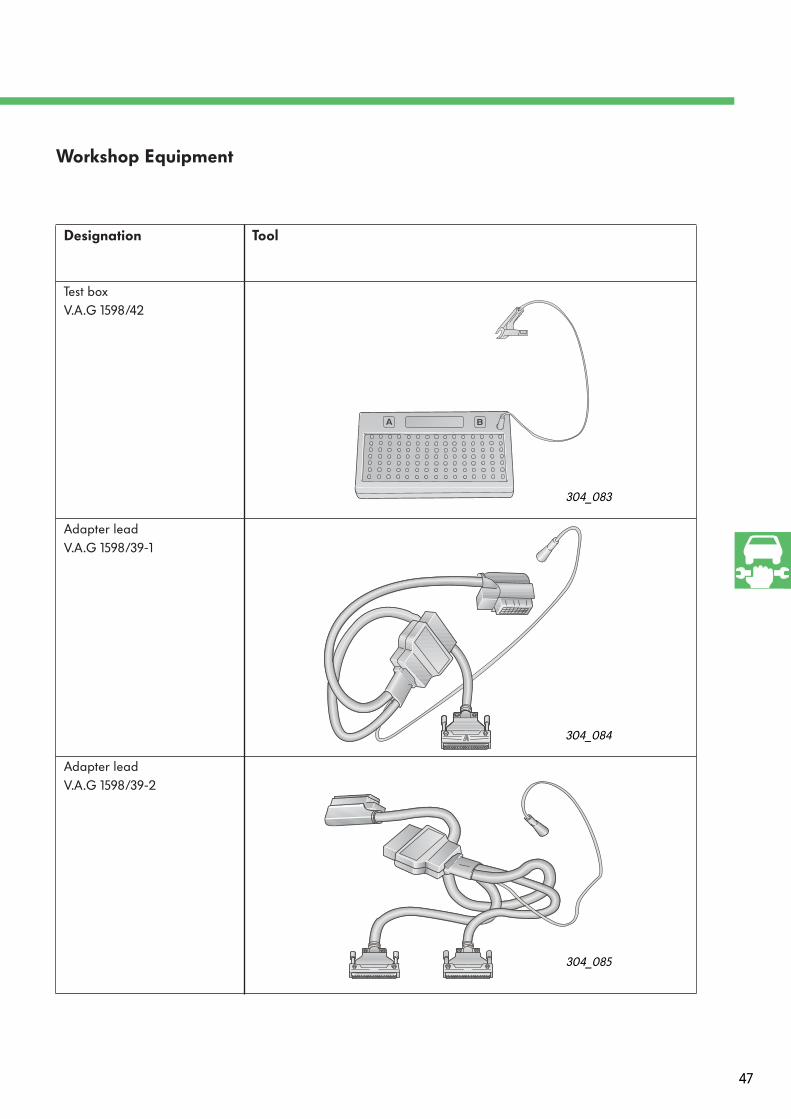
Designation Tool
Test box V.A.G 1598/42
Adapter lead V.A.G 1598/39-1
Adapter lead V.A.G 1598/39-2
Workshop Equipment
304_085
304_084
304_083
48
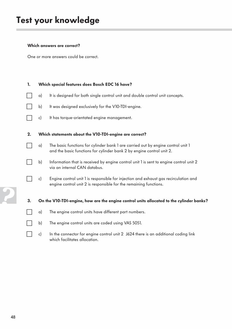
Test your knowledge
Which answers are correct?
One or more answers could be correct.
1. Which special features does Bosch EDC 16 have?
a) It is designed for both single control unit and double control unit concepts.
b) It was designed exclusively for the V10-TDI-engine.
c) It has torque-orientated engine management.
2. Which statements about the V10-TDI-engine are correct?
a) The basic functions for cylinder bank 1 are carried out by engine control unit 1and the basic functions for cylinder bank 2 by engine control unit 2.
b) Information that is received by engine control unit 1 is sent to engine control unit 2 via an internal CAN databus.
c) Engine control unit 1 is responsible for injection and exhaust gas recirculation and engine control unit 2 is responsible for the remaining functions.
3. On the V10-TDI-engine, how are the engine control units allocated to the cylinder banks?
a) The engine control units have different part numbers.
b) The engine control units are coded using VAS 5051.
c) In the connector for engine control unit 2 J624 there is an additional coding link which facilitates allocation.
49
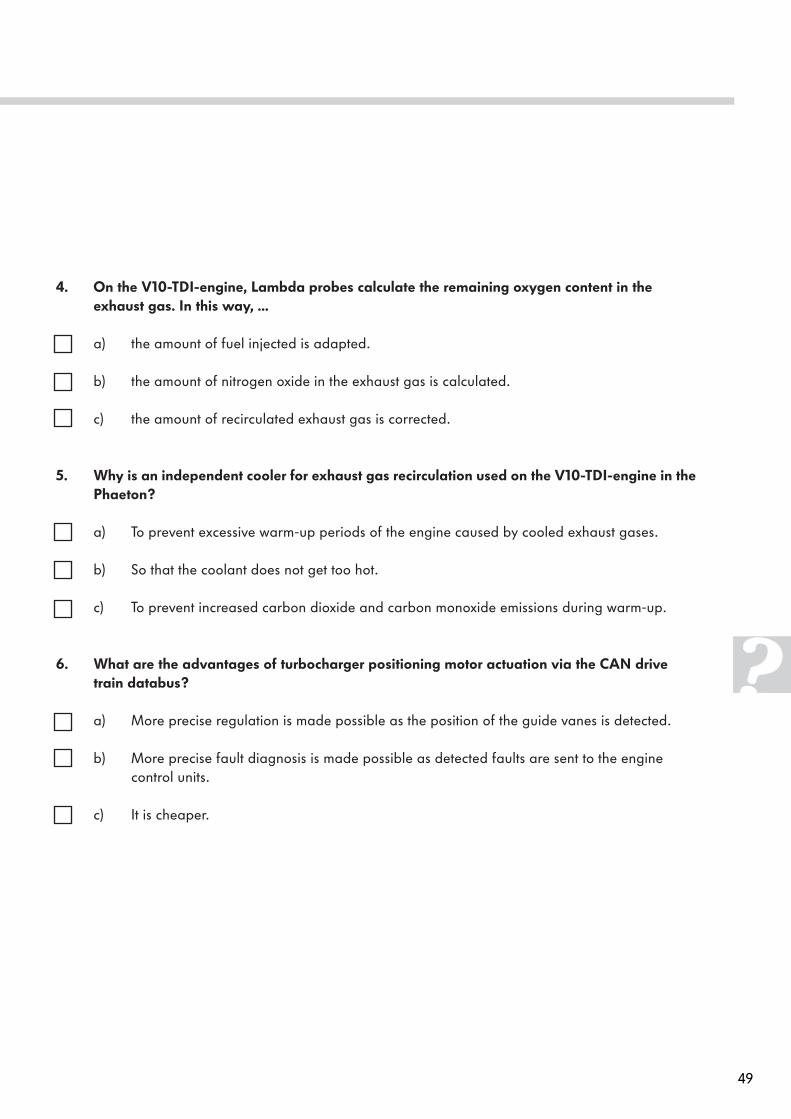
4. On the V10-TDI-engine, Lambda probes calculate the remaining oxygen content in theexhaust gas. In this way, ...
a) the amount of fuel injected is adapted.
b) the amount of nitrogen oxide in the exhaust gas is calculated.
c) the amount of recirculated exhaust gas is corrected.
5. Why is an independent cooler for exhaust gas recirculation used on the V10-TDI-engine in thePhaeton?
a) To prevent excessive warm-up periods of the engine caused by cooled exhaust gases.
b) So that the coolant does not get too hot.
c) To prevent increased carbon dioxide and carbon monoxide emissions during warm-up.
6. What are the advantages of turbocharger positioning motor actuation via the CAN drivetrain databus?
a) More precise regulation is made possible as the position of the guide vanes is detected.
b) More precise fault diagnosis is made possible as detected faults are sent to the engine control units.
c) It is cheaper.
50
7. Which statements about the fuel cooling pump are correct?
a) The fuel cooling pump operates continually while the engine is running.
b) The fuel cooling pump can be found in the Touareg on the V10-TDI-and R5-TDI-engines.
c) The fuel cooling pump is actuated when the fuel temperature is approximately 70 °C.
8. The engine speed sender G28 on the V10-TDI-engine ...
a) sends its signals directly to both engine control units.
b) sends its signals to engine control unit 1 J623 and these are then passed on to engine control unit 2 J624 via an internal CAN databus.
c) sends its signals to engine control unit 1 J623 and these are then passed on to engine control unit 2 J624 via a separate cable.
Test your knowledgeAnswers
1. a, c; 2. a, b; 3. c; 4. c; 5. a, c; 6. a, b; 7. b, c; 8. c

51
Notes
Service.
For internal use only. © VOLKSWAGEN AG, Wolfsburg
All rights reserved. Technical specifications subject to change without notice.
000.2811.24.20 Technical status: 11/02
❀ This paper is produced from
non-chlorine-bleached pulp.
304