electronic emission noticessupport.pcpartner.com/support/man/ati/pa38.pdfelectronic emission notices...
TRANSCRIPT

1
Electronic Emission Notices
Federal Communications Commission (FCC) StatementThis equipment has been tested and found to comply with the limits for a Class B digitaldevice, pursuant to Part 15 of FCC Rules. These limits are designed to provide reasonableprotection against harmful interference in a residential installation. This equipmentgenerates, uses and can radiate radio frequency energy and, if not installed and used inaccordance with instructions contained in this manual, may cause harmful interferenceto radio and television communications. However, there is no guarantee that interferencewill not occur in a particular installation.
If this equipment does cause harmful interference to radio or television reception, whichcan be determined by turning the equipment off and on, the user is encouraged to try tocorrect the interference by one or more of the following measures:
- REORIENT OR RELOCATE THE RECEIVING ANTENNA- INCREASE THE SEPARATION BETWEEN THE EQUIPMENT AND THE RECEIVER- CONNECT THE EQUIPMENT INTO AN OUTLET ON A CIRCUIT DIFFERENT FROM
THAT OF THE RECEIVER- CONSULT THE DEALER OR AN EXPERIENCED AUDIO/TELEVISION TECHNICIAN
NOTE: Connecting this device to peripheral devices that do not comply with Class Brequirements, or using an unshielded peripheral data cable, could also result inharmful interference to radio or television reception.
The user is cautioned that any changes or modifications not expressly approvedby the party responsible for compliance could void the user’s authority to operatethis equipment.
To ensure that the use of this product does not contribute to interference, it isnecessary to use shielded I/O cables.
CopyrightThis manual is copyrighted with all rights reserved. No portion of this manual may becopied or reproduced by any means.
While every precaution has been taken in the preparation of this manual, no responsibilityfor errors or omissions is assumed. Neither is any liability assumed for damages resultingfrom the use of the information contained herein.
TrademarksAll brand names, logos and registered trademarks mentioned are property of theirrespective owners.

2
Technical Reference Booklet
Table of Contents
HARDWARE CONFIGURATION ....................................................... 4Key Features .................................................................................................. 4
MOTHERBOARD LAYOUT ................................................................ 7
REAR PANEL .................................................................................... 8AUDIO CONFIGURATION ................................................................ 10SPEAKER CONFIGURATION ............................................................ 10
Method 1: 4/6 Surround audio output of back panel only ...................... 10Method 2: Using S-Bracket connectors ................................................. 12
CONNECTORS ................................................................................. 15Floppy Disk Drive Connector:CN3......................................................... 15Hard Disk Connectors:CN1&CN2......................................................... 15S-Bracket (SPDIF)/LEN/LFE/Surround Output Connector:J19(optional)................................................................ ................................ 16
TV Out Connector:J3 .............................................................................. 18 IEEE1394 Connectors:J22&J23 ............................................................. 19 Game Connector:J21 ............................................................................. 21 Fan Power Connectors: CPUFAN1/SYSFAN1/WOL................................. 22
CD-IN Connector:J18 ............................................................................ 23AUX-IN Connector:J20 ........................................................................... 23Front Panel Audio Header:FP_S1 ......................................................... 24USB Connectors:FP_U1........................................................................ 25Front Panel Headers:FP1 ...................................................................... 26Serial ATA Hard Disk Connectors:SATA1/SATA2.................................... 27Chassis Alarm Lead:JP13 .................................................................... 29
JUMPER SETTING ............................................................................... 30JP9-CMOS Clear .................................................................................... 30JP2-On Board AC97 Sound Select ........................................................ 30JP7-On Board LAN Select ..................................................................... 30CPU Frequency Jumper: JP8 ................................................................ 31JP3-On Board IEEE1394 Select ............................................................ 31JP12-On Board SATA Select .................................................................. 31

3
SLOTS .............................................................................................. 32
CPU INSTALLATION ........................................................................ 33
MEMORY CONFIGURATIONS .......................................................... 36DDR DIMM Sockets Location ................................................................ 36Install DDR DIMMs................................................................................. 36Memory Configurations ......................................................................... 37
BIOS SETUP ..................................................................................... 38Starting Setup ........................................................................................ 38Main Menu .............................................................................................. 39Standard CMOS Features ..................................................................... 40Advanced BIOS Features ....................................................................... 41Advanced Chipset Features .................................................................. 41Integrated Peripherals ........................................................................... 41Power Management Setup .................................................................... 41PNP/PCI Configurations ........................................................................ 41PC Health Status ................................................................................... 41Set Supervisor/User Password ............................................................. 42Flash Update Procedure ....................................................................... 43
SIL 3112 SATA RAID USER MANUAL ............................................ 44Creating RAID Sets ................................................................................ 44Deleting RAID Sets ................................................................................ 45Resolving Conflict .................................................................................. 45
USING SILICON IMAGE SATARAID GUI ........................................ 46
DRIVER AND RAID SOFTWARE INSTALLATION ............................ 47Microsoft Windows Driver Installation ................................................... 47Install Windows NT4.0,2000,XP ............................................................ 48
APPENDIX ....................................................................................... 48

4
Technical Reference Booklet
HARDWARE CONFIGURATION
Key Features :Chipset
• ATI® RS300+SB200 Chipset.
Processor• Supports the Intel® Celeron, Northwood and Prescott processors in
the 478-pin package (with 0.8V~1.6V voltage).• Supports 64-bit PSB (Processor System Bus) frequency of 400MHz
(100MHz bus clock), 533MHz (133MHz bus clock).• Supports 64-bit PSB (Processor System Bus) frequency of 800MHz
(200MHz bus clock).
VRM 10.0 (Voltage Regulator Modules) on Board• Flexible motherboard design with on board VRD 10.0, easy to upgrade
with future Intel® Celeron, Northwood and Prescott processors.• 0.8375V to 1.600V in 12.5mV steps.
System Memory• A total of four 184pin DDR SDRAM sockets.• DIMM sizes from 64 Mbytes to 4Gbyte.• Support Dual Channel 128-bit Wide Memory Interface.• Support 266/333/400 DDR SDRAM memory type.
System BIOS• PnP, APM, ATAPI and Windows® 2000/XP.• Full support of ACPI & DMI.• Auto detects and supports LBA harddisks with capacities over 160GB.• Easy to upgrade BIOS by end-user.
Plug and Play• Supports Plug and Play specification 1.1.• Plug and play for Windows® 2000, as well as Windows® XP.• Fully steerable PCI interrupts.
TV Out• Integrated TV encoder.• 10-bit DAC with 4-tap filter.• PAL/NTSC TV Out with Composite and S-Video Outputs(Via a header).• ATI’s exclusive “Composite Dot Crawl” freeze option for PAL and
NTSC to improve the picture quality.• TV-Out power management support.

5
Hardware Configuration
On-board I/O• On board two PCI fast IDE ports supporting up to 4 ATA, ATA2 , Ultra
ATA33/66/100 IDE HDDs, CD-ROMs, ZIP drives and LS-120 drives asboot drive.
• One ECP/EPP parallel port.• Two 16550 Compatible UART serial ports.(COM2 is optional)• One floppy port supports two FDD of 360KB, 720KB, 1.2MB , 1.44MB
and 2.88MB capacity.• Six USB ports (two ports via one header).• PS/2 keyboard connector.• PS/2 mouse is supported.• One front panel sound connector.• Infrared (IrDA) is supported via a header.
Expanded USB Support• Includes 2 OHCI host controllers,increasing the number of external
ports to six.• Includes 1 EHCI USB2.0 Host Controller that supports all six
ports(Bandwidth shared between six ports).• This motherboard support USB 2.0 feature only on Windows ®
2000(with SP4 or above)/XP(with SP1 or above) OS.
On-board VGA• Integrated ATI Radeon 9100 IGP.• Supports display (CRT or TV out).• Integrated DAC and CRT controllers.• Full screen/Full speed video playback.• Up to 2048x1536,non-interlaced screen resolution for CRT.
On-board Realtek RTL8100C PCI LAN (optional)• Provides 32-bit performance,PCI bus master capability.• Full compliance with IEEE 802.3u 100 Base-T specifications and
IEEE 802.3X Full Duplex Flow Control.• Supports 10 Mb/s and 100 Mb/s operation.• Supports Wake-On-LAN function and remote wake-up.• Supports ACPI,PCI Power management and PCI VPD.
Full Featured Accelerated Graphics Port (AGP)• Supports AGP3.0 including 4X/8X AGP card.• AGP 1.5V connector support only.• High priority access support.

6
Technical Reference Booklet
Power Management• Supports SMM, APM and ACPI.• Break switch for instant suspend/resume on system operations.• Energy star “Green PC” compliant.• Hardware monitoring circuit is supported, provide voltage, fan speed,
etc. monitoring (optional).• WOL (Wake-On-Lan) Header support.• External Modem Ring-in Wake-up support.• Supports suspend-to-RAM(STR)(optional).
Note: Make sure that the current of your 5VSB power supply is overthan 1.5A.
On-board AC97 Sound (optional)• Integrated AC97 controller with standard AC97 Codec.• Direct Sound and Sound Blaster compatible.• Full-Duplex 16-bit record and play back.• PnP and APM 1.2 support.• Windows® 2000/XP drivers ready.• Line-in, Line-out, Mic-in and MIDI/Game port.• Supports ALC650/ALC655 AC97 codes for six sound channel output
(optional).
On-board IEEE1394(optional)• Compliant with 1394 open HCI specifications v1.0 and v1.1.• Integrated 400Mbit 2 port PHY.
On board Serial ATA host Controller(optional)• Independent DMA operation on two ports.• Data transfer rates of 150Mb/s.• RAID feature support .
Expansion Slots• 1 AGP slot.(supports 1.5V AGP card only).• 5 PCI bus master slots - ver. 2.2 compliant.
Static electricity can harm delicate components of the motherboard.To prevent damage caused by static electricity, discharge the staticelectricity from your body before you touch any of the computerselectronic components.

7
Motherboard Layout (35-AA38-X0-XX)The following diagrams show the relative positions of the jumpers,
connectors, major components and memory banks on the motherboard.
# the LAN ,the Video out and COM2 connectors are optional.# The ALC650/ALC655 embeds an internal analog switch (by driversoftware) to select LINE input or Surround output, and select MIC input orCENTER/LFE output.
NOTE1) Be sure to check the cable orientation in order to match the colored strip to
the pin1 end of the connector.2) When you start up the system, please wait for 5 seconds after you power
on AC.3) It is not recommended to add a metal spacer plate on the back of the
Socket478. Otherwise, some components will be short and damaged.
Motherboard Layout
SATA2

8
Technical Reference Booklet
PIN SIGNAL DESCRIPTION1 VCC +5V/5VSB (optional)2 -Data 0 Negative Data Channel 03 +Data0 Positive Data Channel 04 GND Ground5 VCC +5V/5VSB (optional)6 -Data 1 Negative Data Channel 17 +Data 1 Positive Data Channel 18 GND Ground
Rear Panel The back panel provides the following connectors:
Mouse Connector The mainboard provides a standard PS/2® mouse mini DIN connector forattaching a PS/2® mouse.You can plug a PS/2® mouse directly into thisconnector.
Keyboard Connector The mainboard provides a standard PS/2® keyboard mini DIN connectorfor attaching a PS/2® keyboard.You can plug a PS/2® keyboard directly intothis connector.
USB 2.0 Connector The mainboard provides a OHCI (Open Host Controller Interface) UniversalSerial Bus root for attaching USB devices such as keyboard, mouse or otherUSB-compatible devices.You can plug the USB device directly into theconnector.
USB 2.0 Connector DescriptionUSB 2.0 Connector

9
Serial Port Connectors: COM1 The Port is 16550A high speed communication port that send/receive 16bytes FIFOs. You can attach a serial mouse or other serial devices directly tothe connectors.
Video Out Connector (Optional)The mainboard provides a Video out port to connect a 15-pin analog
video monitor.
LAN Jack (Optional) The mainboard provides one standard RJ-45 jack for connection to LocalArea Network(LAN).You can connect a network cable to the LAN jack.
Parallel Port Connector:LPT1 The mainboard provides a 25-pin female centronic connector as LPT. Aparallel port is a standard printer port that supports Enhanced Parallel Port(EPP) and Extended Capabilities Parallel Port (ECP) mode.
Audio Port Connector SPK_Out is a connector for Speakers or Headphones. Line In is used forexternal CD player, Tape player, or other audio devices. Mic In is a connectorfor microphones.
The ALC650/655 embeds an internal analog switch (by driver software)to select LINE input or Surround output, and select MIC input or CENTER/LFE output.
Rear Panel

10
Technical Reference Booklet
Audio ConfigurationAfter installing the audio driver, you can select 4/6 channel surround
audio output in software utility and then connect surround speakers toappropriate audio ports.
There are two ways to obtain 4/6 channel surround audio output:
1. 4/6 surround audio output of back panel only. All surround speakerconnect to audio connector.
2. S-Bracket (optional cable). You have installed S-Bracket into thecomputer, and then connect two front speakers to back panel’s“Line-out” port, and the rest of speakers to S-Bracket. Detail connectionis refer to Page 17.
Speaker Configuration
Method 1: 4/6 Surround audio output of back panel only.After installing the audio drivers, you can attach the speakers for 2-/4-/6-
channel audio output. Always connect the speakers to the LINE OUTconnectors. Different connector configurations for 2-/4-/6-channeloperations are listed below:
2-Channel 4-Channel 6-ChannelIn 2-channel configuration,Line Out, Line In and MICfunctions all exist.
When set to 4-channelconfiguration, Line Inis replaced by RearSpeaker Out. Line infunction does not exist.
When set to 6-channelconfiguration, Line Inis replaced by RearSpeaker Out. Mic isreplaced by Center/Subwoofer Speaker Out.Line in and Mic do notexist function.

11
Software Configuration
In utility, double click “AC97 Audio configuration” icon from thewindow tray on the right bottom.
Then the “AC97 Audio Configuration” will appear. Click on the SpeakerConfiguration tab to select the audio mode.
A. When you choose 4-channel mode for 4 speaker output, the selected itemis showed as below (Figure1)
(Figure1)
12
Technical Reference Booklet
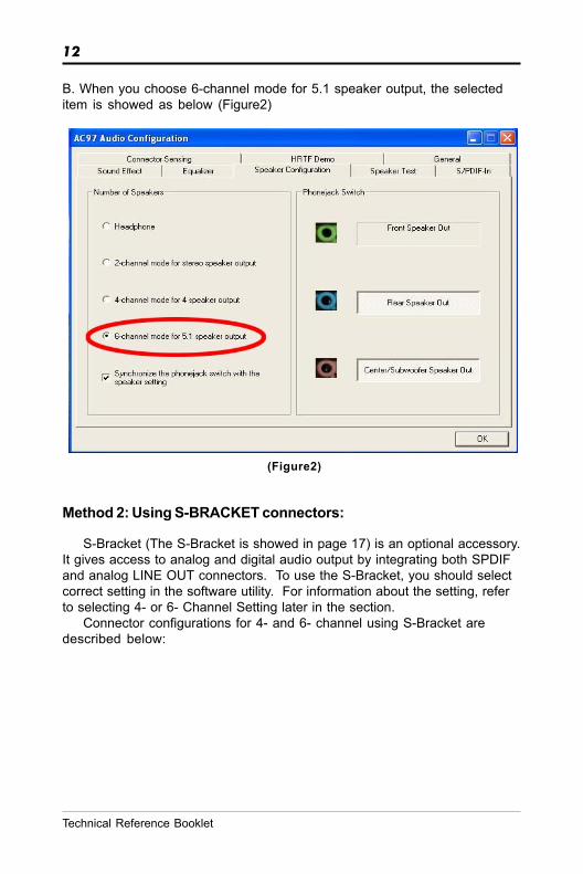
B. When you choose 6-channel mode for 5.1 speaker output, the selecteditem is showed as below (Figure2)
Method 2: Using S-BRACKET connectors:
S-Bracket (The S-Bracket is showed in page 17) is an optional accessory.It gives access to analog and digital audio output by integrating both SPDIFand analog LINE OUT connectors. To use the S-Bracket, you should selectcorrect setting in the software utility. For information about the setting, referto selecting 4- or 6- Channel Setting later in the section.
Connector configurations for 4- and 6- channel using S-Bracket aredescribed below:
(Figure2)
13
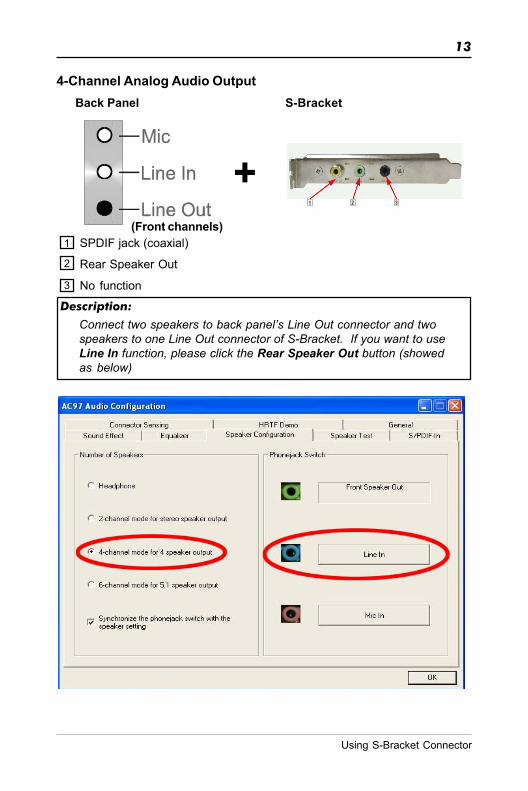
Back Panel S-Bracket
1
2
3
SPDIF jack (coaxial)
Rear Speaker Out
No function
(Front channels)
4-Channel Analog Audio Output
Description:
Connect two speakers to back panel’s Line Out connector and twospeakers to one Line Out connector of S-Bracket. If you want to useLine In function, please click the Rear Speaker Out button (showedas below)
Using S-Bracket Connector
1 2 3
+

14
Technical Reference Booklet
Back Panel S-Bracket
1
2
3
SPDIF jack (coaxial)
Rear Speaker Out
Center and Subwoofer Out
(Front channels)
6-Channel Analog Audio Output
Description:
Connect two speakers to back panel’s Line Out connector and fourspeakers to both Line Out connectors of S-Bracket. If you want to useLine In and MIC function at the same time, please click the RearSpeaker Out and Center/Subwoofer Speaker Out buttons.(showed as below)
1 2 3
+
15
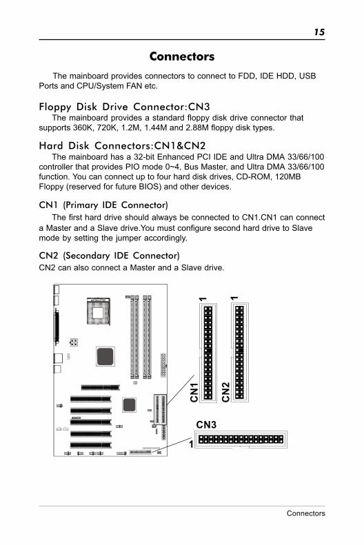
Connectors
The mainboard provides connectors to connect to FDD, IDE HDD, USBPorts and CPU/System FAN etc.
Floppy Disk Drive Connector:CN3The mainboard provides a standard floppy disk drive connector that
supports 360K, 720K, 1.2M, 1.44M and 2.88M floppy disk types.
Hard Disk Connectors:CN1&CN2The mainboard has a 32-bit Enhanced PCI IDE and Ultra DMA 33/66/100
controller that provides PIO mode 0~4, Bus Master, and Ultra DMA 33/66/100function. You can connect up to four hard disk drives, CD-ROM, 120MBFloppy (reserved for future BIOS) and other devices.
CN1 (Primary IDE Connector)The first hard drive should always be connected to CN1.CN1 can connect
a Master and a Slave drive.You must configure second hard drive to Slavemode by setting the jumper accordingly.
CN2 (Secondary IDE Connector)CN2 can also connect a Master and a Slave drive.
CN3
CN
1
CN
2
1
1 1
Connectors

16
Technical Reference Booklet
S-Bracket(SPDIF)/CEN/LFE/Surround Output Connector:J19 (optional)
The connector allows you to connect a S-Bracket for a Digital Interface(SPDIF). The S-Bracket offers 1 SPDIF jacks for digital audio transmissionand 2 analog Line-Out jacks for other 4-channel audio output. So you can useLine in, Mic in and 6 channel audio output features at the same time.
J19
2
1
109

17
PIN SIGNAL DESCRIPTION1 SOUT-L Audio left surrounding output2 SOUT-R Audio right surrounding output3 GND Ground4 GND Ground5 CET-OUT Audio center output6 LFE-OUT Audio bass output7 GND Ground8 SPDIF S/PDIF input9 KEY NC10 SPDFO S/PDIF output
J19-S-Bracket
S-Bracket Cable (optional)
Connect to J19
SPDIF jack (coaxial)Rear Speaker Out
Connectors
Center and Subwoofer Out

18
Technical Reference Booklet
TV Out ConnectorThe mainboard provides TV Out connectors.
J3
1J3 : TV Out
PIN Assignment1 C2 GND3 COMP/B4 Y
TV Out cable
19
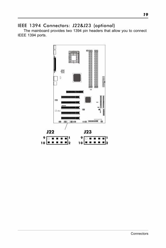
IEEE 1394 Connectors: J22&J23 (optional)The mainboard provides two 1394 pin headers that allow you to connect
IEEE 1394 ports.
1
2
9
10
J22 J231
2
9
10
Connectors

20
Technical Reference Booklet
PIN SIGNAL1 TPA+2 TPA-3 Ground4 Ground5 TPB+6 TPB-7 Cable power8 Cable power9 Key (no pin)10 Ground
J22,J23 Pin Definition
IEEE 1394 Cable (optional)

21
Game Connector: J21The mainboard provides a game port to connect a joystick or a MIDI device.
J211
2
15
16
Game Cable (optional)
Connect to the Game Connector
Connectors
22
Technical Reference Booklet
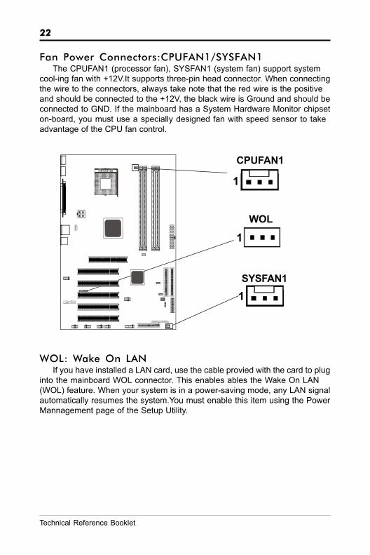
Fan Power Connectors:CPUFAN1/SYSFAN1The CPUFAN1 (processor fan), SYSFAN1 (system fan) support system
cool-ing fan with +12V.It supports three-pin head connector. When connectingthe wire to the connectors, always take note that the red wire is the positiveand should be connected to the +12V, the black wire is Ground and should beconnected to GND. If the mainboard has a System Hardware Monitor chipseton-board, you must use a specially designed fan with speed sensor to takeadvantage of the CPU fan control.
SYSFAN1
CPUFAN1
1
1
1WOL
WOL: Wake On LANIf you have installed a LAN card, use the cable provied with the card to plug
into the mainboard WOL connector. This enables ables the Wake On LAN(WOL) feature. When your system is in a power-saving mode, any LAN signalautomatically resumes the system.You must enable this item using the PowerMannagement page of the Setup Utility.

23
CD-IN Connector:J18The connector is for CD-ROM Drive.
AUX-IN Connector:J20The connector is for Audio Device.
J20J18
1
PIN Assignment1 CD-L2 GND3 GND4 CD-R
CDS1 : J18
AUX1 : J20
PIN Assignment1 AUX-L2 GND3 GND4 AUX-R
1
Connectors

24
Technical Reference Booklet
PIN Assignment1 MIC2 GND3 REF4 POWER5 Front Audio(R)6 Rear Audio(R)7 Reserved8 Key(No pin)9 Front Audio(L)10 Rear Audio(L)
Front Panel Audio Header: FP-S1This mainboard supports front panel microphone and speaker out ports.
If your computer case has these ports,connect them to FP-S1.
FP-S1
Note:If you want to use “Front Audio” connector, you must remove 5-6, 9-10jumper.In order to utilize the front audio header, your chassis must havefront audio connector. Also please make sure the pin assignment on thecable is the same as the pin assignment on the MB header. To find out ifthe chassis you are buying support front audio connector, please contractyour dealer.
10
9
2
1
FP-S1

25
USB Connector: FP-U1This mainboard has USB ports. Some computer cases have a special
module that mounts USB ports at the front of the case. If you have this kindof case, use auxiliary USB connector FP-U1 to connect the front mountedports to the mainboard.
PIN Assignment1 VCC2 VCC3 USBP0-4 USBP1-5 USBP0+6 USBP1+7 GND8 GND9 KEY10 OC#
USB Connector
109
21
FP-U1
Connectors

26
Technical Reference Booklet
Front Panel Header: FP1The mainboard provides one front panel connector for electrical connecti
-on to the front panel switches and LEDs.
FP1
NC
VCC
KEY
KEYLOCKGND
IRRXSPEAKER
GNDKEY
IRTX
NC
VCC
GND
KEYGND
PWR_SWRESET
NCKEY
GNDPW_LED-PW_LED+
HDD_LED-HDD_LED+
24 23
161718
2022 21
19
1513
7
119
531
14
681012
24
27
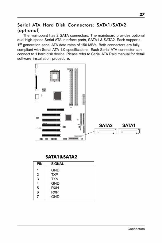
Serial ATA Hard Disk Connectors: SATA1/SATA2(optional)
The mainboard has 2 SATA connectors. The mainboard provides optionaldual high-speed Serial ATA interface ports, SATA1 & SATA2. Each supports1st generation serial ATA data rates of 150 MB/s. Both connectors are fullycompliant with Serial ATA 1.0 specifications. Each Serial ATA connector canconnect to 1 hard disk device. Please refer to Serial ATA Raid manual for detailsoftware installation procedure.
PIN SIGNAL1 GND2 TXP3 TXN4 GND5 RXN6 RXP7 GND
SATA1&SATA2
SATA1SATA2
Connectors

28
Technical Reference Booklet
Serial ATA Cable
Please do not fold the serial ATA cable in a 90-degree angle, whichwill cause the loss of data during the transmission.
Serial ATA Hard Disk Devices Power Cable(optional)
Connect one end of the SATA cable to the mainboard, and connect anotherend to the SATA Hard Disk.

29
Chassis Alarm Lead:JP13(optional)This lead is for a chassis designed with intrusion detection feature.This
requires an external detection mechanism such as a chassis intrusion sensoror microswitch.When you remove any chassis component, the sensor triggersand sends a high-level signal to this lead to record a chassis intrusion event.
PIN Assignment1 +5VSB2 KEY3 Chassis Signal4 GND
JP13 Pin Definition
Note:If you want to use “Chassis Alarm” Connector, you must remove3-4jumper.
JP1
31
Connectors

30
Technical Reference Booklet
Jumper SettingThis chapter explains how to configure the motherboard’s hardware.
Before using your computer, make sure all jumpers and DRAM modules areset correctly. Refer to this chapter whenever in doubt.
1JP9
Clear CMOS Jumper: JP9If you want to clear the system configuration, use the JP9(Clear CMOS
Jumper) to clear data.
JP9 Selection1-2* Normal*2-3 CMOS Clear
Close Open * = Default setting.
JP2-On Board AC97 Sound SelectJP2 Function
1-2* AC97 Sound Enable* 2-3 AC97 Sound Disable
1JP2 JP7
JP7-On Board LAN Select(optional)JP7 Function
2-3* LAN Enable*1-2 LAN Disable
31
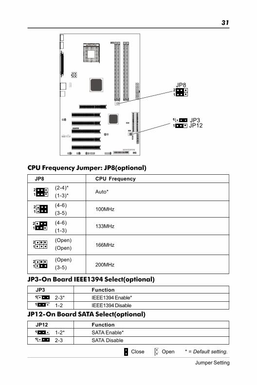
JP8 CPU Frequency(2-4)*(1-3)*
(4-6)(3-5)
(4-6)(1-3)
(Open)(Open)
12
12
Auto*
100MHz
133MHz
166MHz
CPU Frequency Jumper: JP8(optional)
12JP8
Close Open * = Default setting.
12
12
(Open)(3-5)1
2200MHz
JP3JP12
JP3-On Board IEEE1394 Select(optional)
JP3 Function2-3* IEEE1394 Enable*1-2 IEEE1394 Disable
JP12-On Board SATA Select(optional)
JP12 Function1-2* SATA Enable*2-3 SATA Disable
1
Jumper Setting

32
Technical Reference Booklet
SlotsThe motherboard provides one AGP slot,and five 32-bit PCI bus slots.
AGP Slot
PCI Slots
AGP (Accelerated Graphics Port) Slot(optional)The AGP slot allows you to insert the AGP graphics card. AGP is an inter-
face specification designed for the throughput demands of 3D graphics. Itintroduces a 66MHz, 32-bit channel for the graphics controller.
PCI (Peripheral Component Interconnect) SlotsThe PCI slots allow you to insert the expansion cards to meet your needs.
When adding or removing expansion cards, make sure that you unplug thepower supply first. Meanwhile,read the documentation for the expansion cardto make any necessary hardware or software settings for the expansion card,such as jumpers, switches or BIOS configuration.

33
CPU InstallationPlease refer to the following steps to install the CPU.
1. Please turn off the power and unplug the power cord before installing the CPU. Pull the lever sideways away from the socket. Make sure to raise thelever up to a 90 degree angle.
2. Look for the gold arrow. The gold arrow should point towards the lever pivot.The CPU can only fit in the correct orientation.
2. If the CPU is correctly installed, the pins should be completely embeddedinto the socket and can not be seen. Please note that any violation of thecorrect installation procedures may cause permanent damages to yourmainboard.
CPU Installation

34
Technical Reference Booklet
4. Press the CPU down firmly into the socket and close the lever. As the CPUis likely to move while the lever is being closed, always close the lever withyour fingers pressing tightly on top of the CPU to make sure the CPU isproperly and completely embedded into the socket.
5. Position the CPU cooler set onto the CPU.
35
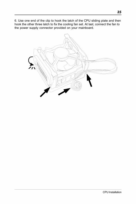
6. Use one end of the clip to hook the latch of the CPU sliding plate and thenhook the other three latch to fix the cooling fan set. At last, connect the fan tothe power supply connector provided on your mainboard.
CPU Installation
36
Technical Reference Booklet
Memory Configurations
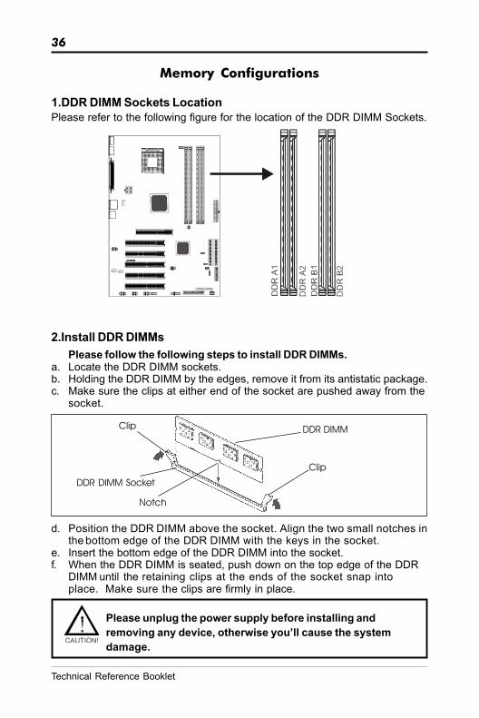
1.DDR DIMM Sockets LocationPlease refer to the following figure for the location of the DDR DIMM Sockets.
2.Install DDR DIMMsPlease follow the following steps to install DDR DIMMs.
a. Locate the DDR DIMM sockets.b. Holding the DDR DIMM by the edges, remove it from its antistatic package.c. Make sure the clips at either end of the socket are pushed away from the
socket.
d. Position the DDR DIMM above the socket. Align the two small notches inthe bottom edge of the DDR DIMM with the keys in the socket.
e. Insert the bottom edge of the DDR DIMM into the socket.f. When the DDR DIMM is seated, push down on the top edge of the DDR
DIMM until the retaining clips at the ends of the socket snap intoplace. Make sure the clips are firmly in place.
Please unplug the power supply before installing andremoving any device, otherwise you’ll cause the systemdamage.
Clip
Clip DDR DIMM
DDR DIMM Socket
Notch

37
Mode/(DIMM Type) Case Sockets - DDR A1 DDR A2 DDR B1 DDR B2 Single-channel/ 1 Populated ---- ---- ---- (DDR400/DDR333 2 ---- Populated ---- ---- DDR266) 3 ---- ---- Populated ----
4 ---- ---- ---- Populated
Dual-channel/ 1 Populated ---- Populated ---- (DDR333/DDR266) 2 ---- Populated ---- Populated
3 Populated Populated Populated Populated
Dual-channel/ 1 Populated ---- Populated ---- (DDR400) 2 ---- Populated ---- Populated
Memory Configurations
3. Memory ConfigurationsPlease refer to the following recommended memory configurations in Table1.
Table 1 Recommended memory configurations
In dual channel mode, always install an identical (the same type andsize) DDR DIMM pair in sockets of the same color.You can install identical DIMMs in DDR A1 and DDR B1 and identicalDIMMs in DDR A2 and DDR B2.When using DDR400 DIMMs, it is recommended to install only onemodule per channel.
Note: • It is not recommended to use the three DIMMs configuration.• Memory channel speed is determined by slowest DIMM populated in system.• Installing DDR DIMMs other than the recommended configurations or Using
memory modules not in the recommemded vendor list may cause systeminstability, the system reliability may not be guaranteed.
Please refer to the following recommended DDR400 vendors list in Table 2.Table 2 Recommended memory modules
Size Vendor Part Number Chip Brand Chip Number256M Infineon HYS64D32300GU-5-B Infineon HYB250256800BT-5
KingMax -- KingMax KDL388P4EA-50Transcend -- Transcend A2S56D30ATP-5Kingston KVR400X64C3A/256 Hynix HY5DU56822BT-D43Kingston KVR400X64C3A/256 Winbond W942508CH-5Kingston KVR400X64C3A/256 Mosel Vitelic V58C2256804SAT-5OEM -- Samsung K4H560838E-TCCCMicroworks M368L3223ETM-CCC Samsung K4H560838E-TCCCAdata -- Adata ADD8608A8A-5BNANYA -- NANYA NT256D64S88BIG-5TCORSAIR CMX256A-3200LL -- --GEIL GE2563200B -- --
512M Infineon HYS64D64300GU-5-B Infineon HYB250256800BT-5Microworks M368L6423ETM-CCC Samsung K4H560838E-TCCCKingston KVR400X64C3A/512 Kingston D3208DL1T-5Kingston KVR400X64C3/512 Kingston D3208DL1T-5Hynix HYMD264646B8J-D43AA Hynix HY5DU56822BT-D43

38
Technical Reference Booklet
BIOS SetupThis chapter discusses Award’s Setup Program built into the ROM BIOS. The SetupProgram allows users to modify the basic system configuration. This special informationis then stored in battery-backed RAM, which retains the setup information when thepower is turned off.
Starting SetupThe Award BIOS is immediately activated when you turn on the computer. The BIOSreads the system information contained in the CMOS and begins the process of checkingout the system and configuring it. When it finishes, the BIOS will seek an operatingsystem on one of the disks and then launch and turn control over to the operatingsystem.
While the BIOS is in control, the Setup Program can be activated :
1. By pressing <Del> immediately after switching the system on, or2. By pressing the <Del> key when the following message appears briefly at
the bottom of the screen during the POST (Power On Self Test )
Press DEL to enter SETUP
If the message disappears before you can respond and you still wish to enter Setup,restart the system to try again by turning it OFF then ON or pressing the “RESET” buttonon the system case. You may also restart by simultaneously pressing the <Ctrl>, <Alt>,and <Delete> keys. If you do not press the keys at the correct time and the system doesnot reset, an error message will be displayed and you will again be asked to ...
PRESS F1 TO CONTINUE, DEL TO ENTER SETUP
Getting HelpPress F1 to pop up a small help window that describes the appropriate keys to use andthe possible selections for the highlighted item. To exit the Help Window press <Esc> orthe F1 key again.
In Case of ProblemsIf, after making and saving system changes with the Setup Program, you discover thatyour computer does not reset, use the Award BIOS defaults to override the CMOSsettings.
39
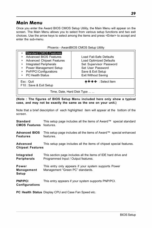
Main MenuOnce you enter the Award BIOS CMOS Setup Utility, the Main Menu will appear on thescreen. The Main Menu allows you to select from various setup functions and two exitchoices. Use the arrow keys to select among the items and press <Enter> to accept andenter the sub-menu.
Phoenix - AwardBIOS CMOS Setup Utility
8 Standard CMOS Features8 Advanced BIOS Features Load Fail-Safe Defaults8 Advanced Chipset Features Load Optimized Defaults8 Integrated Peripherals Set Supervisor Password8 Power Management Setup Set User Password8 PnP/PCI Configurations Save & Exit Setup8 PC Health Status Exit Without Saving
Esc : Quit : Select ItemF10 : Save & Exit Setup
Time, Date, Hard Disk Type ... ...
(Note : The figures of BIOS Setup Menu included here only show a typicalcase, and may not be exactly the same as the one on your unit.)
Note that a brief description of each highlighted item will appear at the bottom of thescreen.
Standard This setup page includes all the items of Award™ special standardCMOS Features features.
Advanced BIOS This setup page includes all the items of Award™ special enhancedFeatures features.
Advanced This setup page includes all the items of chipset special features.Chipset Features
Integrated This section page includes all the items of IDE hard drive andPeripherals Programmed Input / Output features.
Power This entry only appears if your system supports PowerManagement Management “Green PC” standards.Setup
PNP/PCI This entry appears if your system supports PNP/PCI.Configurations
PC Health Status Display CPU and Case Fan Speed etc.
BIOS Setup

40
Technical Reference Booklet
Load Fail-Safe The BIOS defaults have been set by the manufacturer and representDefaults settings which provide the minimum requirements for your system
to operate.
Load Optimized The chipset defaults are settings which provide for maximumDefaults system performance. While Award has designed the
custom BIOS to maximize performance, the manufacturerhas the right to change these defaults to meet its needs.
Set Supervisor/ Changes, sets, or disables password. It allows you to limitUser Password access to the system and the Setup Program.
Save & Exit Saves value changes to CMOS and exits setup.Setup
Exit Without Abandons all CMOS value changes and exits setup.Saving
Standard CMOS FeaturesThe items in Standard CMOS Setup Menu are divided into 10 categories. Each categoryincludes one or more setup items. Use the arrow keys to highlight the item and then usethe <PgUp> or <PgDn> key to select the desired value in each item.
Phoenix - AwardBIOS CMOS Setup UtilityStandard CMOS Features
Date (mm :d d : y y ) Wed. Jan 01 2003 Item HelpTime (h h :mm:ss) 11 : 1 : 35
Menu Level 88IDE Primary Master [Press Enter 4303 MB]8IDE Primary Slave [None] Change the day, month,8IDE Secondary Master [None] year and century8IDE Secondary Slave [None]
Drive A [1.44M, 3.5 in.]Drive B [None]
Video [EGA/VGA]Halt on [All, but keyboard]
Base Memory 640KExtended Memory 30720KTotal Memory 31744K
Move Enter: Select +/-/PU/PD : Value F10 : Save ESC : Exit F1 :General HelpF5 : Previous Values F6 : Fail-Safe Defaults F7 : Optimized Defaults
(Note : The figures of BIOS Setup Menu included here only show a typicalcase, and may not be exactly the same as the one on your unit.)

41
Date The date format is <day-of-the-week>. <month> <day> <year>.
Time The time format is <hour> <Minute> <second> displayed in24-hour military-time clock. For example, 1 p. m. is displayedas 13:00:00.
Primary These categories identify the types of the two channels thatMaster/Primary have been installed in the computer.Slave/SecondaryMaster/Secondary If the controller of the HDD interface is SCSI, the selection shall
be “None”.
Drive A Type / This category identifies the types of floppy disk drive A or driveDrive B Type B that has been installed in the computer.
Video The default setting is EGA/VGA.
Halt on You can select which type of error will cause the system to halt.
Advanced BIOS FeaturesThis section allows you to configure your system for basic operation. You have theopportunity to select the system’s default speed, boot-up sequence, keyboard operation,shadowing and security.
Advanced Chipset FeaturesThe Chipset Features Setup option is used to change the values of the chipset registers.These registers control most of the system options in the computer.
This section allows you to configure the system based on the specific features of theinstalled chipset. This chipset manages bus speeds and access to system memoryresources, such as DRAM and the external cache. It must be stated that these itemsshould not be altered. The default settings have been chosen because they provide thebest operating conditions for your system.
Integrated PeripheralsThe Integrated Peripherals Setup allows the user to configure the onboard IDE controller,floppy disk controller, the printer port and the serial ports.
Power Management SetupThe Power Management Setup Menu allows you to configure your system to most saveenergy while operating in a manner consistent with your own style of computer use.
PNP/PCI ConfigurationsThis section describes how to configure the PCI bus system. This section covers somevery technical items and it is recommended that only experienced users should makeany changes to the default settings.
PC Health StatusThe PC Health Status display CPU and Case Fan Speed.
BIOS Setup

42
Technical Reference Booklet
Set Supervisor/User PasswordYou can set either supervisor or user password, or both of them. The differencebetween them are:
Supervisor Password : You can enter the Setup Program and changethe options of the setup menus.
User Password : You can enter the Setup Program but can notchange the options of the setup menus.
When you select this function, the following message will appear at the center of thescreen to assist you in creating a password.
ENTER PASSWORD:
Type the password, up to eight characters in length, and press<Enter>. The new passwordwill clear the previously entered password from the CMOS memory. You will be asked toconfirm the password. Type the password again and press <Enter>. You may alsopress <Esc> to abort the selection and operate without a password.
To disable a password, just press <Enter> when you are prompted to enter the password.A message will be displayed to confirm that the password is disabled.
PASSWORD DISABLED.
Once the password is disabled, the system will reset and you can enter the SetupProgram freely.
When a password is enabled, you will be prompted to enter it every time you try to entersetup. This prevents an unauthorized person from changing any setting of your systemconfiguration.
In addition, when a password is enabled, you can require the BIOS to request a passwordevery time your system is rebooted. This would further prevent unauthorized use ofyour computer.
The password requirement is defined by the Security Option of the BIOS Features SetupMenu. If the Security Option is set to “System”, the password will be required both atresetting and at entering setup. If the option is set to “Setup”, the prompt only appearswhen you try to enter setup.
43
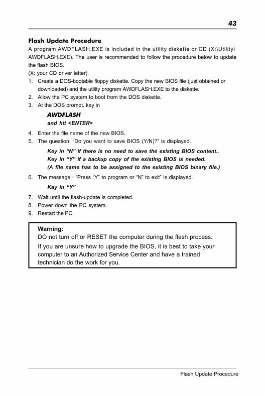
Flash Update ProcedureA program AWDFLASH.EXE is included in the utility diskette or CD (X:\Utility\AWDFLASH.EXE). The user is recommended to follow the procedure below to updatethe flash BIOS.(X: your CD driver letter).1. Create a DOS-bootable floppy diskette. Copy the new BIOS file (just obtained or
downloaded) and the utility program AWDFLASH.EXE to the diskette.2. Allow the PC system to boot from the DOS diskette.3. At the DOS prompt, key in
AWDFLASHand hit <ENTER>
4. Enter the file name of the new BIOS.5. The question: “Do you want to save BIOS (Y/N)?” is displayed.
Key in “N” if there is no need to save the existing BIOS content..Key in “Y” if a backup copy of the existing BIOS is needed.(A file name has to be assigned to the existing BIOS binary file.)
6. The message : “Press “Y” to program or “N” to exit” is displayed.
Key in “Y”
7. Wait until the flash-update is completed.8. Power down the PC system.9. Restart the PC.
Warning:DO not turn off or RESET the computer during the flash process.If you are unsure how to upgrade the BIOS, it is best to take yourcomputer to an Authorized Service Center and have a trainedtechnician do the work for you.
Flash Update Procedure

44
Technical Reference Booklet
SiL 3112 SATA RAID User ManualCreating and deleting RAID sets is a function found in the BIOS. During bootup, thefollowing message will appear, pausing for a few moments to allow the user tochoose what to do:
Press <CRTL-S> or F4 to enter RAID utility
An easy-to-use screen will appear with the following choices in the top left:
Create RAID SetDelete RAID SetRebuild RAID SetResolve Conflicts
Below this will be listed the drives currently installed on the system.
The top right half of the screen displays directions and comments for the user. Thebottom right half lists the command keys:
Arrows up and down are Select KeysESC takes the user to the previous menuEnter selects the user’s choiceCtrl-E exits the utility
Creating RAID SetsBecuase SATARaid supports two drives, creating RAID Sets is a simple procedure.
1. Select “Create RAID Set.”2. Choose either a “Striped” or “Mirrored” RAID Set.3. Select if you want the utility to Auto Configure the RAID Set or if you want to manually
configure the RAID Set. For Striped Sets, you can change the chunk size. ForMirrored Sets, you assign which is the Source and Target drives, as well as if youwant Disk Copy.
What is Disk Copy? If the disk assigned as the source disk already has beenpartitioned and has data stored on it, and then a second disk is added for redundancy,the data on the source drive can be copied to the destination drive, so the disks areidentical, and all subsequent data will be written to both drives as a Mirrored set. If,however,the source disk does not have data already stored on it, there is no needfor Disk Copy.
4. The utility will ask “Are You Sure?” before completing the configuration.

45
Deleting RAID Sets1. To remove one or more RAID sets, select “Delete RAID Set.”2. Select desired set and press Y when asked “Are You Sure?”
Resolving ConflictWhen a RAID set is created, the metadata written to the disk includes drive connectioninformation (Primary Chanel, Secondary Channel). If, after a disk failure, the replacementdisk was previously part of a RAID set (or used in another system), it may have conflictingmetadata, specifically in reference to the drive connection information. If so, this willprohibit the RAID set from being either created or rebuilt,In order for the RAID set tofunction properly, this old metadata must be first overwritten with the new metadata.To resolve this, select “Resolve Conflict” and the correct metadata, including the correctdriveconnection information, will be written to the replacement disk.
SiL 3112 SATA RAID User Manual
46
Technical Reference Booklet
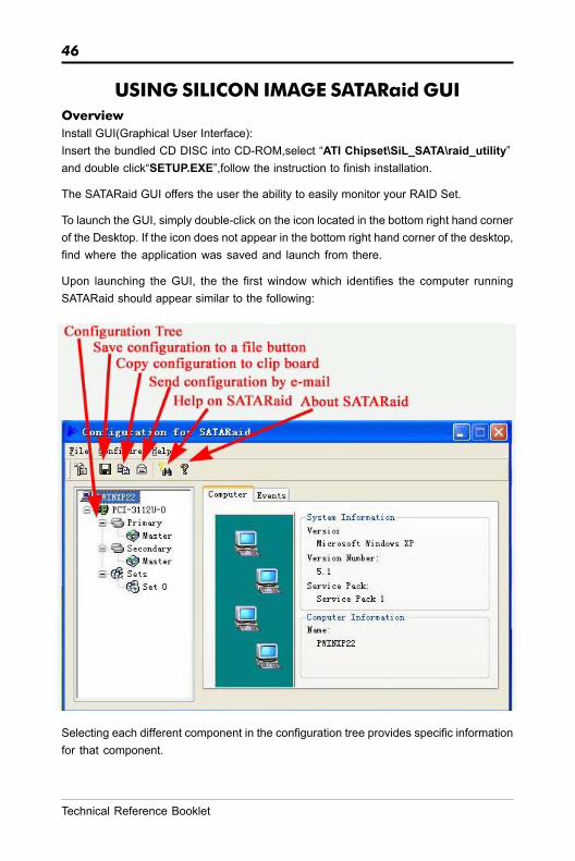
USING SILICON IMAGE SATARaid GUIOverviewInstall GUI(Graphical User Interface):Insert the bundled CD DISC into CD-ROM,select “ATI Chipset\SiL_SATA\raid_utility”and double click“SETUP.EXE”,follow the instruction to finish installation.
The SATARaid GUI offers the user the ability to easily monitor your RAID Set.
To launch the GUI, simply double-click on the icon located in the bottom right hand cornerof the Desktop. If the icon does not appear in the bottom right hand corner of the desktop,find where the application was saved and launch from there.
Upon launching the GUI, the the first window which identifies the computer runningSATARaid should appear similar to the following:
Selecting each different component in the configuration tree provides specific informationfor that component.

47
DRIVER AND RAID SOFTWARE INSTALLATION
Microsoft Windows Driver Installation1. After Windows has finished booting up, the system will automaticallyfind the newly installed adapter and prompt the Found New Hardware Wizard window. Click Cancel to skip it.
2. Insert the bundled driver CD DISC into your CD-ROM drive,select “SiL SATA RAID Driver”installation bar on the dialogue Window to begin thedriver and software installation.(Please follow the instruction to finish theinstallation)
Driver and RAID Software Installation
48
Technical Reference Booklet
APPENDIX
Note to User:The bundled driver CD attached an Auto-Run feature for all the driversthat the motherboard need. Please select the drivers that you wantto install and click the button on the installation panel.
Install Windows NT 4.0,2000,XP1.Insert the bundled driver CD DISC into CD-ROM(G:).Copy all filesfrom directory ( G:\ATI chipset\SiL_SATA\RAID\ ) to a floppy disk.2.Install OS from CD-ROM.3.Press “F6” when display “Press F6 if you need to install a third partySCSI or RAID driver...”4.Insert floppy disk.5.Choose the OS device driver wanted for loading.6.Install OS.7.Install driver after OS is installed.
0283A8