electronic-magnetic measuring system · pdf filefitting manual 4 packaging, scope of delivery,...
TRANSCRIPT

Electronic-magnetic measuring system
Fitting manual and system description

2
Page
Fitting manual4 Packaging, scope of delivery, storage4 Scope of delivery4 Storage
4 Marking of the magnetic strip5 Structure of the magnetic strip5 Structure of the covering strip5 Applies to LMST only6 Guidelines on adhesive bonding of magnetic and covering strips6 Application of pressure and bond strength6 Ambient temperature and adhesive bonding
7 Designs of measuring system8 LMST + EP
Position of the magnetic strip on the guideway9 Fitting of the magnetic strip9 Fitting steps
10 Mounting the carriage10 Laying of cable for LMST + EP/MP10 Laying of cable for LMSD
10 Removing the carriage10 Fitting of electronic evaluation system
System description for design LMSD11 Measuring system for absolute length measurement12 Electrical connection of measuring system12 Anti-interference protection12 Connection allocation
13 Setting of parameters14 Initial operation14 Definition of LEDs in 24 V operation14 LED 114 LED 214 LED 3
15 Calibration of measuring system16 Monitored functions during 24 V operation16 Battery voltage16 Distance between sensor and strip16 Function monitoring of the SSI options card
17 SSI interface17 Application example
Contents

3
Page
18 Serial service interface – RS48518 Service standard protocol18 Programming19 Interfaces for parameters20 SIKONETZ3 protocol22 Error messages22 Synchronisation22 Telegram example23 8 bit system status to register bit allocation23 8 bit configuration register to 0 bit allocation23 8 bit configuration register to 1 bit allocation24 Actor output24 Speed dependency of actor output24 Troubleshooting
System description for design LMST + EP, LMST + MP25 Measuring system for incremental length measurement26 Electrical connections26 Guidance on freedom from interference26 Measures required26 Power supply27 Connection type
28 Positional display MA 10/430 Connection of insert housing EG30 Connector allocation for incremental measuring system30 Connection scheme for absolute measuring system
31 Programming mode
Appendix32 Configuration of parameters on LMST (incremental)33 Configuration of parameters on LMSD (absolute digital)

4
Fitting manual and system description
Electronic-magnetic measuring systemFitting manual
Packaging, scope of delivery, storageThe magnetic strip is supplied packaged.
Scope of deliveryThe delivery comprises (Figure 1):■ the two-component magnetic strip �
– a magnetised, highly flexible plastic strip– a magnetised, flexible steel strip
■ the covering strip �
– a magnetically permeable steel strip.
Storage
In order to prevent stresses in the strip, the strip should only be stored either laid flat or rolled up. The magnetised plastic strip � must face outwards (Figure 2). If the strip is stored rolled up, the radius must not be less thanthe minimum radius Rmin = 100 mm.
Store the magnetic strip in its original packaging at:■ 50% relative humidity
■ +20 °C ambient temperature.
Note the storage life date on the strip.
Marking of the magnetic stripThe magnetic strip can be identified by the continuous printing (Figure 3).
Figure 1 · Scope of delivery
Figure 2 · Position of the plastic strip and minimum radius
Figure 3 · Marking of the magnetic strip
205
06
6
1
2
Rmin = 100 mm
1
1
205
067
Series number
Strip accuracy:005 = 0,05 mm
Pole width: 5 mm
Reference point: 0 = no fixed reference point E = Reference point once
NNNN 00 5 0500 0
205
068

5
Structure of the magnetic stripThe magnetic strip has a two-component structure (Figure 4):■ A magnetised, flexible steel strip � is firmly attached to
the underside of a magnetised, highly flexible plastic strip �. A protective film � is applied to the underside of the steel strip.
The steel strip protects the magnetic strip against mechanical damage and at the same time performs a magnetic short circuit function. This gives a decisive increase in the functional safety of the measuring system under extreme magnetic influences.
Keep the magnetic strip away from magnetic fields (magnetic holders, permanent magnets, etc.) at all times.
The magnetic strips can only be fitted once the guideways are correctly mounted on the adjacent construction.
Magnetic strips can only be attached by adhesive once.
Structure of the covering stripThe covering strip (Figure 5) is a magnetically permeable steel strip � that is supplied separately. Once the magnetic strip is fitted, the covering strip is attached by adhesive in the upper guideway slot and then protects the plastic strip against damage and contamination.
A protective film � is applied to the underside of the covering strip.
Applies to LMST onlyIf no current is flowing, movement or adjustment of the magnetic sensor will not be detected or recorded by the downstream electronics.
Figure 4 · Structure of the magnetic strip
Figure 5 · Covering strip
205
06
9
1
2
3
205
070
1
2

6
Fitting manual and system description
Electronic-magnetic measuring system
Fitting manual
Guidelines on adhesive bonding of magnetic and covering strips
In order to achieve optimum bonding, remove all anti-adhesive substances (oil, grease, dust, etc.) from the surfaces to be bonded.
The surfaces to be bonded must be dry.
Use only cleaning agents that vaporise without leaving a residue; INA recommends Loctite 7 061. Alternatively, a 1:1 mixture of isopropanol and water can be used.
When using solvents, always observe the information and guidance provided by the solvent manufacturer.
Application of pressure and bond strengthThe contact developed between the adhesive and the surfaces to be bonded is decisive for the strength of the bond. High pressure will give good surface contact. The bond will be stronger the more pressure is applied.
Pressure can be applied with the aid of a clean cloth folded over several times.
Ambient temperature and adhesive bondingThe ideal temperature range for adhesive bonding is between +20 °C and +30 °C in a dry room.
Adhesive bonding is inadvisable if the temperatures of the surfaces to be bonded are � +10 °C. At these temperatures, the adhesive is too solid and it is practically impossible to achieve adequate immediate adhesion.
If the magnetic strip was bonded correctly, the bond is stable even at minus temperatures.
Based on experience, the final adhesive strength of the bond is achieved after 72 hours. The ideal temperature for hardening is +21 °C.

7
Designs of measuring systemThe position of the reference point and the position of the incremental mark (above or below) on the magnetic strip can be localised using a magnetic magnifying glass or a film (Figure 6 or Figure 7).
Figure 6 · Magnetic strip MB500-LMST + EP
Figure 7 · Magnetic strip MB500-LMSD
Table 1 · Design
Measuringsystem
Guideway Refer-encesignal
Magnetic strip Accuracy class (relative)
LMST + EPLengthMeasuring System, incremental TTL withonE referencePoint
TKVD..LMSD.. Single-point
MB500-LMST + EP KL3 �25 �m
LMST + MPLengthMeasuring System, incremental TTL with Multiple reference Point
Multiple-point
MB500-LMSD
LMSDLengthMeasuring System,absoluteDigital.
–
205
071
appr
ox 5
mm
10
mm
Incremental mark
Reference mark
= North
= South
Signal period: 5 mm
205
07
2
Signal period: 5 mm
= North
= South
10
mm

8
Fitting manual and system description
Electronic-magnetic measuring system
Fitting manual
LMST + EPPosition of the magnetic strip on the guidewayThe mounting position of the strip is dependent on the position of the measuring head:■ if the measuring head is on the right of the carriage,
the incremental mark is below (Figure 8)
■ if the measuring head is on the left of the carriage, the incremental mark is above (Figure 9)
The measuring head has one sensor each for the incremental mark � and the reference point � (Figure 10).
Figure 8 · Measuring head on right of carriage
Figure 9 · Measuring head on left of carriage
Figure 10 · Measuring head with two sensors � and �
Locating face Incremental mark below
205
07
3
Locating face
Incremental mark aboveIncremental mark above
205
074
1
2
205
078

9
Fitting of the magnetic strip
The magnetic strip must be flat to the mounting surface or the area to be measured. Waviness will always impair the measurement accuracy.
Where long strips are to be fitted, remove a short length of the protective film and fix the strip in place. Then align the strip. Remove the remaining protective strip from the side while pressing the strip down.
Fitting steps■ Press the dummy guideway � against the guideway �
(Figure 11).
■ Push the carriage � carefully onto the dummy guideway �.
■ Store the carriage in a clean dry location; do not remove the dummy guideway from the carriage.
■ Carefully clean the fixing surface in the guideway slot �; see page 6, Guidance on adhesive fixing of magnetic and covering strips.
■ Remove the protective film � of the adhesive strip � on the magnetic strip � progressively while attaching the strip (Figure 12).
■ Attach the magnetic strip � (see page 6, Guidance on adhesive fixing of magnetic and covering strips, see Figure 12).
■ Carefully clean the surface of the magnetic strip.
■ Fix the covering strip � in place (see page 6, Guidance on adhesive fixing of magnetic and covering strips, see Figure 13).
■ Deburr the ends of the covering strip.
Sharp edges on the covering strip will damage the seal lips of the carriage.
Figure 11 · Sliding the carriage off the guideway
Figure 12 · Attaching the magnetic strip
Figure 13 · Attaching the covering strip
2
3
1
205
07
5
7
5
6
4
7
5
205
076
8
8
205
077a

10
Fitting manual and system description
Electronic-magnetic measuring system
Fitting manual
Mounting the carriage
Ensure that the covering strip is deburred.Make sure the connection cable is not subjected to tensile load during fitting.
■ Locate the dummy guideway with the carriage against the guideway and slide the carriage onto the guideway.
Laying of cable for LMST + EP/MPIt is recommended that the cable is guided in a flexible cable trunking system. Note the minimum bending radius of 50 mm.
Laying of cable for LMSDFor short stroke lengths (� 300 mm), the cable should be laid rigidly or guided in a flexible cable trunking system. For a flexible cable trunking system, note the minimum bending radius of 50 mm.
For long stroke lengths (� 300 mm), the electronic evaluation system should be mounted on the moving part and the cable laid rigidly.
Removing the carriage■ Detach the cables
■ Locate the dummy guideway against the guideway
■ Push the carriage onto the guideway
■ Store the carriage and guideway in a clean dry location.
Leave the dummy guideway in the carriage.
Fitting of electronic evaluation system
Ensure that the fixing screws for the electronic evaluation system cannot become loose.
■ Mount the electronic evaluation system on a flat surface using two suitable screws– The holes on the housing have a diameter of 5,2 mm
■ Make the connection for potential equalisation between the screw head and the housing.
Figure 14 · Fitting the carriage
Figure 15 · Removing the carriage
Figure 16 · Fitting the electronic evaluation system
205
11
920
5 1
2020
5 12
1

11
Fitting manual and system description
Electronic-magnetic measuring system
System description for design LMSD
Measuring system for absolute length measurementTechnical data (Table 2 and Figure 17):■ Magnetic linear travel measurement (absolute)
■ KUVE..LMSD �
■ Electronic evaluation system ASA 510 �.
Figure 17 · Measuring system for absolute length measurement – LMSD
21
205
021a
Table 2 · Technical data
Feature Technical data Additional information
Operating voltage 24 V DC �20% Standard
Cable length 2 m as standard (fixed) between measuring headand electronic evaluation system
Measurement length max. 83 m –
Dimensional scale 1 mark, pole pitch 5 mm –
Positional detection Current-free, 3 V lithium battery, life approx. 7to 10 years depending on ambient temperature
–
Cable sheath PUR, oil-resistant Standard
Output switchingoptions
SSIRS485
Standard (to RS422 A, max. 1 MHz)ASCII protocol
Resolution 0,010 mm, internally adjustable –
Power consumption � 100 mA Reverse polarity protection
Connection type D-SUB 9 pin –
Housing for electronic evaluation system Sheet steel Zinc electroplating
Interference protection class 3 to IEC 801
Traverse speed max. 6 m/s (of magnetic sensor) –
Distance between strip and sensor max. 2 mm Over complete measurement length
System accuracy �(0,025 + 0,01�L) mm;[L in m]
at Tu = +20 °C;[L = length per metre started]
Repeat accuracy �1 digit (�0,01 mm) –
Temperature range Working temperature 0 °C to +60 °C Storage temperature –20 °C to +70 °C
Humidity (electronic evaluation system) max. 95% rF Dew formation not permissible
Protection type (electronic evaluation system)
IP 40 to DIN VDE 0470 CE inspection symbol
Mass approx. 550 g Electronic evaluation system + cable + measuring head

12
Fitting manual and system description
Electronic-magnetic measuring system
System description for design LMSD
Electrical connection of measuring system
All wiring work should only be carried out in a voltage-free condition.
Electrical connections should only be made or disconnected in a voltage-free condition.
Before switching on, check all connection cables and plug connections.
Anti-interference protectionThe connections on the device are protected against external interference from, for example, logic systems, motors, clocked controllers etc. However, interference may affect the sensor and connection cable.
Select the connection cables, guidance of cables and location of the system such that inductive or capacitative interference is kept to a minimum.
Only shielded connection cables should be used. Cable shielding should be provided on both sides, a cable cross-section of 0,25 mm2 should be used. Connection cables should not be laid parallel to cables carrying power.
The shielding should be connected to the housing of the electronic evaluation system (mass) in a star shape and over a large area (low impedance).
The system LMSD is highly sensitive to a lack of earthing. The housing must be earthed over a large area (low impedance).
The shielding must be connected to the potential equalisation over a large area (low impedance).
For this purposes, the delivery includes a ring ear and, as an alternative, a flat plug connector and a toothed disc for connection of a cable (max. 2,5 mm2). The connection should be as short as possible.
The measuring system should be positioned as far as possible from cables carrying interference signals. If necessary, shrouds or metallised housings should be used.
Safety coils should be wired with blow-out coils.
The device is matched ex works to the rigidly connected sensor head and can be put into operation once the parameters are set. The sensor cable cannot be extended or divided.
Connection allocationThe output signals and power are fed via a 9 pin D-SUB plug.
Screw the plug to the connector on the housing in order to ensure a stable electrical connection.
For allocation of connections, see Table 3.
SSI and interface RS 485 are not active at the same time. The active data output is selection using the DIP switch 1 before switching on the device.
Table 3 · Connector allocation for D-SUB plug, 9 pin male
Pin Designation Description
1 +24 V DC Power +24 V DC � 5%, � 200 mA, reverse polarity protection
2 SSI■ Clock (+)
Positive SSI clock input, opto-decoupled, 150 R series resistance to RS422
3 SSI■ Data (+)orRS485■ DÜA
Positive SSI data output (if DIP SW-1 ON)
RS485 data output (if DIP SW-1 OFF)
4 Actor Uin Not allocated (power actor (max. 24 V/0,5 A))
5 GND Ground
6 Actor GND Not allocated (Ground actor (not connected to Pin 5))
7 SSI■ Clock (–)
Inverted SSI clock input
8 SSI■ Data (–)orRS485■ DÜB
Inverted SSI data output (if DIP SW-1 ON)
RS485 data output (if DIP SW-1 OFF)
9 Actor Out Not allocated (PNP output actor (max. 24 V/0,5 A))

13
Setting of parametersParameters are set using six DIP switches. DIP switches 1 to 4 are only read in during switch-on.
DIP switches 1 to 4 must be set before switching onthe 24 V net (see Table 4).
DIP switches 5 to 6 are polled while the system is powered by the 24 V net.
DIP switch 1 sets the operating mode (SSI or RS485).
■ SSI (Table 4):– Clock input are designed with opto-decoupling and are
provided with a 150 � series resistance. As soon as a clock signal is present, LED 1 lights (see page 14) even if the 24 V supply to the electronic evaluation system is not switched on.
The SSI clock outputs correspond to RS422.
Table 4 · Operating mode SSI (“SSI mode”)
DIP Position Description
1 ON Operating mode SSI
2 OFF
ON
Positional value outputted in Gray code (default)Positional value outputted in binary code
3 OFFON
Count direction POSITIVE (default)Count direction NEGATIVE
4 OFF
ON
Speed monitoring in positive count direction (default)Speed monitoring in negative count direction
5 OFF Calibration switch
6 OFF Initialisation
Table 5 · Operating mode RS485 (“RS485 mode”)
DIP Position Description
1 OFF Operating mode RS485
2 OFFON
RS485 service standard protokoll (default)RS485 SIKONETZ3 protocol
3 – No function in RS485 mode
4 – No function in RS485 mode
5 OFF Calibration switch
6 OFF Initialisation

14
Fitting manual and system description
Electronic-magnetic measuring system
System description for design LMSD
Initial operation
Before initial operation, it must be ensured thatthe following have been carried out correctly:– fitting– wiring– parametrising.
Initial operation takes place after switching on the 24 V supply. After switch-on, the device will run a “startup routine”. For example, the DIP switches will be read and any option cards initialised. After approx. one second, readiness for operation will be shown by LED 2 lighting.
Definition of LEDs in 24 V operationLED 1ON■ as soon as an external SSI clock signal is supplied.
Also when 24 V net switched off due to opto-decoupling.
LED 2ON■ during 24 V online
Flashing■ Li battery � 2,8 V, must be replaced at factory.
LED 3OFF■ Default.
ON■ Strip/sensor distance � 2 mm (24 V online).
Figure 18 · Housing
LED 1: SSI clock active
LED 2: Online/LoBatt
LED 3: ERROR
SupplySens.
DIP SW
205
07
9

15
Calibration of measuring system
The measuring system is a “quasi absolute” measuring system, i.e. the information on the positional value is not present as an absolute value on the scale.
Calibration is necessary in the following cases:■ after sensor fitting
■ after replacement of the buffer battery
■ if the sensor has been moved too far from the magnetic strip.
During calibration, the current positional value is replaced by the calibration value set and is stored in non-volatile form.
The positional value is preset ex works to “0”. The calibration value can be changed via RS485and is also stored in non-volatile form.
Calibration in operating mode SSI■ Place the sensor on the mechanical reference point
■ Set DIP-switch 5 to the ON position
■ After a second set it to the OFF position.
Completion of calibration is indicated by a single short blink of LED 3 (see page 14).
Calibration in operating mode RS485■ Place the sensor on the mechanical reference point
■ Set DIP switch 1 to the OFF position
■ Set DIP switch 2 to the OFF position (service mode protocol)
■ Enter interface command “S00000”
or
■ Place the sensor on the mechanical reference point
■ Set DIP switch 1 to the OFF position
■ Set DIP switch 2 to the ON position (Sikonetz 3 protocol)
■ Enter interface commands 32 hex, 48 hex, 33 hexor
■ Set DIP switch 5 to the ON position
■ Wait one second
■ Set DIP switch 5 to the OFF position.

16
Fitting manual and system description
Electronic-magnetic measuring system
System description for design LMSD
Monitored functions during 24 V operationBattery voltageThe condition of the internal buffer battery is continuously monitored. If the voltage drops below � 2,8 V, LED 2 will start to flash.
In operating mode RS485, bit 1 is set in the system status register. This error status is automatically cancelled when the battery is replaced.
The battery can only be replaced by the manufacturer.
Distance between sensor and stripDuring 24 V operation, the distance between the sensor head and magnetic strip is continuously monitored.
This monitoring is not suitable for monitoring of manufacturing and assembly tolerances.
If the sensor lifts to � 3 mm or more, LED 3 (ERROR) is switched on and the error is stored. Storage of the error (ERROR) must be cleared. The method of clearing is dependent on the operating mode.
Clearing the error status in operating mode SSIIn SSI mode, the SSI driver is switched off, which allows subsequent control in the same way as, for example, a cable breakage.
The error status is cleared in three steps:■ Place the magnetic sensor above the strip within the
assembly tolerances states and position it on the mechanical reference point
■ Set DIP switch 6 to the ON position
■ Wait at least one second
■ Set DIP switch 6 to the OFF position
LED 3 will now flash: 3�briefly, pause, 3�briefly■ Set DIP switch 5 to the ON position
■ Wait at least one second
■ Set DIP switch 6 to the OFF position.
LED 3 will go out, the SSI driver will be switched on again and the positional value will be outputted as valid.
Clearing the error status in operating mode RS485Bit 0 and bit 2 will be set in the system status register. With DIP 2 in the OFF position, command W or Z will output the fixed positional value +99999999. With DIP 2 in the ON position, command 16h will output the fixed positional value 8388555.
The error status is cleared as in the operating mode SSI. After clearing, the positional value is outputted as valid again and bit 0 and bit 2 are reset in the system status register.
Alternatively, clearing can be carried out via the RS485 interface in four steps instead of using the DIP switches:■ Place the magnetic sensor above the strip within the
assembly tolerances states and position it on the mechanical reference point
Inputting the following command will reset all parameters to the factory setting and reprogramming must be carried out.
■ Enter “S11100”
■ Enter “S00000”
■ Reprogram parameters.
Function monitoring of the SSI options cardIn operating mode SSI, communication between the SSI card and basic card is continuously monitored.
If there is a malfunction:■ the SSI driver is switched off
■ bit 4 is set and stored in the system status register
■ LED 3 flashes: 2�briefly, pause, 2�briefly.
The error status is cleared as follows:■ Set DIP switch 6 to the ON position
■ Wait at least one second
■ Set DIP switch 6 to the OFF position.
17
SSI interfaceThe integrated SSI interface of the ASA510 allows synchronous output of the positional value.
The data format covers a range of 24 bits (1 bit (MSB) sign + 23 bits for positional value) that are outputted aligned right. The output code is expressed in Gray or binary (see Table 2). All subsequent bits (25, 26...) are outputted as “0”.
The data signals conform to the standard RS422. The clock inputs are opto-decoupled and also conform to RS422. The SSI monoflop time is typically 20 �s to 25 �s, giving the minimum clock rate of 62,5 kHz. The maximum clock rate is 1 MHz and is essentially restricted, in relation to data security, by the length of the connection cable.
Guide values according to Table 6 can be specified.
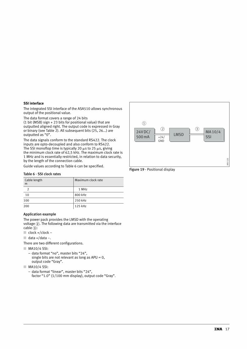
Application exampleThe power pack provides the LMSD with the operating voltage �. The following data are transmitted via the interface cable �:■ clock +/clock –
■ data +/data –.
There are two different configurations.
■ MA10/4 SSI:– data format “no”, master bits “24”,
single bits are not relevant as long as APU = 0, output code “Gray”.
■ MA10/4 SSI:– data format “linear”, master bits “24”,
factor “1.0” (1/100 mm display), output code “Gray”.
Figure 19 · Positional displayTable 6 · SSI clock rates
Cable lengthm
Maximum clock rate
2 1 MHz
10 800 kHz
100 250 kHz
200 125 kHz
24V DC/500 mA
MA 10/4SSI+24/
GND
LMSD
1
2 3
205
12
2

18
Fitting manual and system description
Electronic-magnetic measuring system
System description for design LMSD
Serial service interface – RS485The RS485 interface on the rear of the electronic evaluation system can be used for the programming of parameters.
Service standard protocolThis protocol allows parametrising, positional value output and diagnosis of the electronic evaluation system. The data signals conform to the standard RS485. The protocol is not bus-compatible and therefore no other devices should be connected to the RS485.
ProgrammingBefore programming of the electronic evaluation system using a PC is started, the system must be prepared:■ set DIP switch 1 to the OFF position
■ set DIP switch 2 to the OFF position
■ connect the components in accordance with Figure 20– connect the RS485 interface of the electronic evaluation
system with the RS232 interface of the PC. Use a level converter
– connect the electronic evaluation system to the power pack.
Switch on the power supply to the electronic evaluation system and start programming. For programming, you can use a suitable terminal program or programming tool.
If using the terminal program (e.g. sikoterm.exe), enter the commands manually. A list of commands is given on page 19.
The programming tool asa_demo.exe allows parameters to be entered using the function keys. All relevant parameters are displayed at the same time.
The terminal program sikoterm.exe and asa_demo.exe can be requested from INA.
Figure 20 · Block diagram for programming
Electronicevaluationsystem
Levelconverter PC
24V DC/500 mA
205
12
3

19
Interfaces for parameters:■ 19200 baud, no parity, 8 bit, 1 stop bit, no handshake
■ ASCII
■ 2/3 byte: 0 to 65535 (0 to �223)
■ Upper and lower case accepted■ All response telegrams (exception: command W) are
completed with a CR (= hex13).
Table 7 · Command list
Command Response Comments
Bytes Example
A0 10 ASA 510 � [CR] Hardware identification
A1 7 V0,06 � [CR] Software version
A2 19 RS485/hardware SSI � [CR] Type of interface
B 10 +####### � [CR] Positional value without correction values for ASCII code
Fy+ 2 � [CR] Enter 3 byte valuey = 3:calibration value (default = 0) � xxxxxxx = decimal value
H 4 – For internal purposes: parameter data
K – – Software reset
Q 18 – For internal purposes: parameter data
S00000 2 � [CR] Set positional value to calibration value
S11100 2 � [CR] Restore default condition(ADC channel 2/3, count direction POSITIVE, SSI Gray code, no RS485 start message, speed monitoring ON in positive count direction, delete spacing error, delete calibration data)
S00014 2 � [CR] Switch off speed monitoring
S00015 2 � [CR] Speed monitoring, any direction
S00016 2 � [CR] Speed monitoring in positive count direction
S00017 2 � [CR] Speed monitoring in negative count direction
T0 2 � [CR] Count direction POSITIVE (default)
T1 2 � [CR] Count direction NEGATIVE
U 17 – For internal purposes: parameter data
V 2 – For internal purposes: speed sample rate 250 ms in 1/100 mm
W 4 #### Absolute positional value in binary code
X 6 0�## � [CR] Output system status register
Y0 6 0�## � [CR] Configuration register - output 0
Y1 6 0�## � [CR] Configuration register - output 1
Z 10 + ####### � [CR] Absolute positional value in ASCII code

20
Fitting manual and system description
Electronic-magnetic measuring system
System description for design LMSD
SIKONETZ3 protocolThis protocol allows parametrising and positional value output of the electronic evaluation system. The data signals conform to the standard RS485. Each telegram contains an address and communication with 31 devices is possible via a bus.
In the default condition, every electronic evaluation system has the address 01. Before an electronic evaluation system is connected to the bus, the address should be reprogrammed via the service standard protocol. Switching to the SIKONETZ3 protocol is then possible.
The SIKONETZ3 protocol is designed as a master/slave system, where an electronic evaluation system is a slave. There are two telegram lengths (3 bytes or 6 bytes, Figure 21).
The test byte is generated as follows:■ delete address byte
■ link remaining bytes with EXOR.
AO to A4:■ binary code address 1 to 31, address 0 reserved for master.
RR:■ broadcast bit = 1st command valid for all devices.
Device does not respond.
L:■ length bit.
1 = short telegram (3 bytes). 0 = long telegram (6 bytes).
Figure 21 · Telegram and address byte
3 bytes:
6 bytes:
Address byte:
Addressbyte
Testbyte
Command
Addressbyte
Databyte,low
Databyte,middle
Databyte,high
Testbyte
Command
1 0 A0 A1 A2 A3 A4 0 RR L 1
Start Stop
205
12
5

21
Command list:■ 19 200 baud, no parity, 8 bit, 1 stop bit, no handshake.
1) Hexadecimal value of command.2) Telegram length from master to electronic evaluation system.3) Telegram length from electronic evaluation system to master.4) Parameters transferred are stored in electronic evaluation system in non-volatile form.5) Command is necessary to switch on programming mode.6) Command is broadcastable.
Table 8 · Command list
Hex1) TX2) RX3) S4) P5) R6) Function
16 hex 3 6 – – – Read out positional value
18 hex 3 6 – – – Read out calibration value
1b hex 3 6 – – – Read out device nameD-byte 1: name = 24D-byte 2: software versionD-byte 3: hardware version
1d hex 3 6 – – – Read out count direction0: up (+)1: down (–)
28 hex 6 6 S P – Program calibration valueValue is set to the positional value if the device is calibrated (command 0�48)
2d hex 6 6 S P – Program count direction0: up (+)1: down (–)
32 hex 3 3 – – – Programming mode onProgramming mode must be on in order to program parameters (0�28 and 0�2d)
33 hex 3 3 – – – Programming mode offDefault
3a hex 3 6 – – – Output system status
3b hex 3 3 – – – Delete system statusSystem status bytes 2 and 3 are deleted
48 hex 3 3 S P – Positional value is set to calibration value
4f hex 3 3 – – R Freeze positional valuePositional value is frozen. Condition is restored by reading out positional value.Used for synchronised reading out of several devices

22
Fitting manual and system description
Electronic-magnetic measuring system
System description for design LMSD
Error messagesThe slave (electronic evaluation system) detects transmission or input errors and sends one of the following three error messages.
1) Hexadecimal value of command.2) Telegram length from master to electronic evaluation system.3) Telegram length from electronic evaluation system to master.4) Parameters transferred are stored in electronic evaluation system
in non-volatile form.5) Command is necessary to switch on programming mode.6) Command is broadcastable.
SynchronisationByte/telegram synchronisation is carried out via timeout. A timeout means that, within a telegram, the time spacing of the individual bytes must not exceed the following maximum value:■ 10 ms.
If an electronic evaluation system is contacted but does not respond, the master can only send another telegram at the earliest after the following time:■ 30 ms.
Telegram exampleThe positional value of the device with address 7 is to be outputted.
Master sends (hex): 87 16 91
Short telegram to address 7 (87h); read out positional value (16h); test byte (91h)
Electronic evaluation system responds (hex): 07 16 03 02 00 10
Long telegram from address 7 (07h); read out positional value (16h);value 203h = 515 dec (03 02 00h); test byte (10h)
Table 9 · Error messages
Hex1) TX2) RX3) S4) P5) R6) Function
82 hex – 3 – – – Data transmission error in test total
84 hex – 3 – – – Unacceptable or unknown command
88 hex – 3 – – – Unacceptable value(programming parameter)

23
8 bit system status to register bit allocation
8 bit system status to register bit allocation
8 bit configuration register to 1 bit allocationTable 10 · System status register
Bit no. Default Comments
0 0 ■ Is set as soon as strip/sensor spacing � �3 mm■ Remains set as long as system connected to
+24 V■ Delete using DIP SW-4 (ON/OFF) or
RS485 – S11100
1 0 ■ Is set as soon as lithium battery � 2,8 V■ Resetting once battery has been replaced
2 0 ■ Is set as soon as traverse speed in direction to be monitored � �25 m/min
■ Resetting as soon as � �25 m/min
3 0 ■ For internal purposes: software counter offset
4 0 ■ Is set if communication error occurs with options card
■ Delete using DIP SW6 (ON/1 sec/OFF)
Table 11 · Configuration register 0
Bit no. Default Comments
0 0 ■ When set, an identification key is sent via RS485 (if active) after +24 V switched on = start message
1 0 ■ Count direction 0 = POSITIVE■ Count direction 1 = NEGATIVE
2 1 ■ SSI code 0 = binary■ SSI code 1 = Gray
3 0 ■ For internal purposes: software counter
4 1 ■ For internal purposes: ADC channel select
5 0 ■ Software filter 0 = OFF■ Software filter 1 = ON
6 1 ■ not used
7 0 ■ not used
Table 12 · Configuration register 0
Bit no. Default Comments
0 to 4 0 ■ not used
5 0 ■ Speed monitoring 0 = OFF■ Speed monitoring 1 = ON
6 1 ■ Direction of speed monitoring 0 = POSITIVE■ Direction of speed monitoring 1 = NEGATIVE
7 0 ■ Speed monitoring, all directions 0 = OFF■ Speed monitoring, all directions 1 = ON

24
Fitting manual and system description
Electronic-magnetic measuring system
System description for design LMSD
Actor outputThe switching output of the electronic evaluation system is designed with opto-decoupling to 24 V power supply.PIN 4 of the D-SUB (actor Uin) can be set to an external voltage (max. 30 VDC). Set the associated GND to PIN 6. The potential actor Uin is switched through to PIN 9 (actor OUT). The maximum load capacity is � 0,5 A.
Speed dependency of actor outputWhen the function “Speed monitoring” is released, the travel speed of the sensor head is monitored in a 250 ms time frame. At a travel speed � � 25 m/min, the actor output “Actor OUT” of the sensor is switched to high resistance and bit 2 is set in the system status register. When the speed decreases to � � 25 m/min, BIT 2 is automatically deleted and the actor output “Actor OUT” is closed against “Actor Uin”.
TroubleshootingTypical problems that may occur at initial operation and during operation:■ the electronic evaluation system is not correctly connected
(pin allocation, see Table 3)
■ the spacing tolerance between the sensor/strip was not observed (over the whole measurement length) or the sensor is grazing the magnetic strip
■ cable break/cutting by sharp edges/crushing
■ the active side of the sensor is facing away from the strip
■ there are magnetic fields in the immediate vicinity of the measurement area
■ incorrect measurement values due to EMC interference
■ the operating mode set does not match the hardware connected.
Figure 22 · Actor output – schematic circuit diagram
PIN 4
PIN 9
PIN 6
100
42
0

25
Fitting manual and system description
Electronic-magnetic measuring system
System description fordesign LMST + EP, LMST + MP
Measuring system for incremental length measurementTechnical data (Table 13 and Figure 23):■ Magnetic linear travel measurement (incremental)
■ KUVE..LMST + EP with one reference point
■ KUVE..LMST + MP with multiple reference point
■ Magnetic sensor type MSK 500/1.
Figure 23 · Measuring system for incremental length measurement – LMST + EP, LMST + MP
173
53
3a
Table 13 · Technical data
Features Technical data Additional information
Operating voltage 24 V DC �20% Standard, reverse polarity protection
Connection type/cable length Open cable ends, 2 m cable (standard) 5 m and 7 m cables possible
Cable sheath PUR, oil-resistant Standard
Output switching Line Driver (LD) standard 5V square wave initial signal to RS422
Reference signal Periodic index (LMST + MP)Fixed index (LMST + EP)
–
Resolution 0,005 mm standard –
Power consumption max. 70 mA @ 24 V DC under zero load
Output signals A Quad B 5V TTL –
Traverse speed max. 6,9 m/s (of magnetic sensor) –
Distance between strip and sensor max. 1,5 mm Over complete measurement length
System accuracy �(0,030 + 0,01�L) mm;L in m
at +20 °C;L = length per metre started
Repeat accuracy �1 increment = �0,005 mm –
Temperature range Operating temperature –10 °C to +70 °C Storage temperature –30 °C to +80 °C
Humidity 100% relative humidity Dew formation permissible

26
Fitting manual and system description
Electronic-magnetic measuring system
System description for design LMST + EP, LMST + MP
Electrical connections
Wiring work must only be carried out free from voltage.
Before switching on, check all connection cables and plug connections.
Guidance on freedom from interferenceAll connections must be protected against external interference. The location must be selected such that inductive or capacitative interference cannot affect the sensor or its connection cable.
Interference (e.g. from power pack parts, motors, clocked controllers or contactors) can be reduced by suitable cable guidance and wiring.
Measures requiredOnly shielded cable should be used. Cable shielding should be provided on both sides. Flex cross-section of cables min. 0,14 mm2; max. 0,5 mm2.
Wiring of the shielding and mass (0V) must be carried out in a star shape and over a large area. The shielding must be connected to the potential equalisation over a large area (low impedance).
The system must be fitted as far away as possible from cables carrying interference; if necessary, additional measures such as shrouds or metallised housings should be used. Avoid laying cables parallel to power cables.
Safety coils should be wired with blow-out coils.
Power supplyThe voltage values are dependent on the sensor design and are given in the delivery paperwork and on the type plate, e.g. 24 V DC �20%.
Observe the maximum length of the connection cable between the sensor and downstream electronics.
In order to prevent thermal overload, use terminators � 470 � if:– operating voltage = 24 VDC– output switching = LD– index signal = I– reference signal = R.

27
Connection typeConnection with open cable ends:■ remove sheathing (to approx. 40 mm)
■ cut off sheathing and twist
■ strip insulation and twist cords to approx. 5 mm
■ swage on end sleeve for strands.
Figure 24 · Connection type
Table 14 · Connection allocation
Cords Signal Cord colour
1 A red
2 B orange
3 I blue
4 UB brown
5 GND black
6 A/ yellow
7 B/ green
8 I/ violet
205
08
0
5
As short as possible
Sheathing

28
Fitting manual and system description
Electronic-magnetic measuring system
Positional display MA 10/4
The display MA 10/4 is an electronic measurement display (Table 15 and Figure 25).
In conjunction with an incremental emitter or angle encoder (SSI), the MA10/4 forms an electronic measurement and display system, alternatively with an electronic signal emitter the MA10/4 forms an electronic display system for distance measurement.
In the standard design, the electronic measurement display MA10/4 is used for displaying angles, distances and speeds. Due to the microcontroller and front-mounted keyboard, the display is freely programmable for the relevant application (see Programming mode, page 31). Since it can be programmed for the specific application, this gives the user the facility for simple stockholding of incremental emitters and measurement displays.
In the design “incremental”, the display has an integral actual value memory as standard that stores the last available value when it is switched off. This value is displayed when it is switched back on. As with all incremental measurement systems, however, it is recommended that the system is set to zero or a reference run carried out when it is switched on.
Figure 25 · Positional display MA 10/4
Table 15 · Ordering data for MA 10/4
Positional display Ordering data
Designation EG = insertion housing
Operating voltage (optionally) 1 = 230 V AC +6/–10%
2 = 24 V DC +/–20%
Emitter input For LMST + EP / LMST + MPLD/24 = RS422/24 V
For LMSDSSI/24 = RS422/24 V
205
02
2a

29
The technical data for the positional display are described in Table 16, the dimensions are shown in Figure 26.
Figure 26 · Electronic positional display MA 10/4 – dimensions
Table 16 · Technical data for MA 10/4
Features Technical data
Display LCD with high contrast, dot matrix. 12 characters
Display range (–) 199999 to (+) 999999
Count frequency 500 kHz
Count capacity 223 increments
Pulse evaluation 4 X
Connectors Plug bar
Protection type IP40 for complete device
IP60 on front face, with mounting in control panel
Operating temperature 0 °C to +50 °C
Storage temperature –20 °C to +85 °C
Housing EG: plastic,with panel clip as snap-fit module
Mass approx. 500 g
SiKO
96
45
max. 5
48 42,5
89,5
19 8
111
+0,6
92+0,8
Panel cutoutDIN 43700
205
033b

30
Fitting manual and system description
Electronic-magnetic measuring system
Positional display MA 10/4
Connection of insert housing EG
Connector allocation for incremental measuring system (see Table 17 and Figure 27)
Connection between the electronic evaluation system ASA 510 (plug Sub-D 9 pin) and the controller or measurement display MA10/4 must be carried out individually by the customer since this is dependent on the controller (plug type, cable length).
Connection scheme for absolute measuring system LMSD (see Table 18 and Figure 28) Figure 27 · Connection scheme for LMST + EP / MP
Figure 28 · Connection scheme for LMSD SSI
Table 17 · Cable allocation for LMST + EP / MP
PIN no. LMST EP
1 brown +Ub
2 red Sig A
3 orange Sig B
4 blue Index signal
5 black GND and shield
15 yellow Sig ! A
16 green Sig ! B
17 violet Index signal
Table 18 · LMSD SSI
PIN no. LMSD SSI
1 (+) Ub (supply)
2 Clock (+)
3 Data (+)
5 GND (interface)
15 Clock (–)
16 Data (–)
1 2 3 4 5 6
14 15 16 17 18 19 20 21 22 23 24 25 26
7 8 9 10 11 12 13
Incremental emitterLD (Line Driver)PP (push pull)OC (open collector)OP (push pull)
Shielding
Referenceswitch
Interface
GND
GN
D
GN
D
GN
D
GN
D
PE
N(OV)
L(+UB)
RSF
Akk
+
Inde
x si
gnal
Emit
ter
supp
ly
DÜ
_A(R
S48
5)
DÜ
_B(R
S48
5)
TD(R
S23
2)
RD(R
S23
2)
Akk
-Ca
paci
tor m
odul
e
Akk
EN
Sig
A
Sig
B
Inde
x si
gnal
(LD
)
(LD
)
(LD
)
_ __
Sig
A
Sig
B
205 082
1 2 3 4 5 6
14 15 16 17 18 19 20 21 22 23 24 25 26
7 8 9 10 11 12 13
Shielding
GNDGND
GN
D
GN
D
GN
D
InterfaceGND
PE
N(OV)
L(+UB)
CAL
Emit
ter
supp
ly
DÜ
_A(R
S48
5)
DÜ
_B(R
S48
5)
TD(R
S23
2)
RD(R
S23
2)
Angle encoder SSI
Calibration switch
_Cl
ock
_D
ata
Cloc
k+
Dat
a+
205 083

31
Programming modeIn order to modify and program the parameters on the display, the keyboard is used to switch to programming mode (see Accessing programming mode, booklet MA 10/4 – User information).
Programming of the display is normally only carried out once at initial operation and set-up of the device and application.
The measurement display MA 10/4 is supplied ex works with a default setting.
Legend for Figure 29
Figure 29 · Programming mode – key functions
� Programming key� Selection key “Value”� Selection key “Position”� Save key.
205
08
4
1 2 3 4

32
Appendix
Configuration of parameters on LMST (incremental)
Table 19 · Parameter list for LMST
Parameter Initial allocation (default) Description
Language deu Language
DEZ 0.000 Number of places after decimal comma
APU 00.020 Display per revolution
DIVISOR 1 Display divisor
STR 00001 Input of emitter line count
DREHRICHT i Count direction of measuring system. i: positive clockwise
INDEX I-short Width of index signal. Short: precisely one increment wide
RFS Opener Reference switch typeContact type of reference point emitter,which can be designed as a mechanical switch or proximity switch (terminal 7, 9)Opener: Opener contact, normally closed
REF +000.000 Reference valueDatum point of measuring system. If the reference value and offset are 0, the display can be zeroed
OFF +0000.000 Offset valueFreely selectable value that influences the display. The offset can, for example, be used for tooling correction or as a displacement
RESET On Release for reset function using star keyOn: reset function active
F-KETTM Off Release of incremental dimension functionSwitching between absolute dimension and zeroing with subsequent relative dimensionOff: Incremental dimension function blocked
F-REF/OF Off Release of reference/offset modificationOff: Reference/offset modification blocked
ISP On Actual value memoryThe last measurement value displayed is stored in non-volatile form when the operating voltage is switched offOn: Actual value memory function switched onWhen the operating voltage is switched on, the last measurement value displayed is displayed again
P-TASTE 5s Programming keyDelay on P key for changing between input and programming modeUnit: seconds
BAUD 4800 Baud rate of interface
EINH mm Unit of measurement
D.WINKEL 0 Display angleSetting of LCD contrast. Value range: –5 to +4
CODE 00000 For service only
CONTROL Off For service only

33
Appendix
Configuration of parameterson LMSD (absolute digital)
Table 20 · Parameter list for LMSD
Parameter Initial allocation (default) Description
Language deu Language
G-TYP multi Emitter typemulti: multiturn emitter
FORMAT None Data formatNone: emitter data left aligned (MSB first)
STR 00001 Input of emitter line count
S-BITS 12 Input of single turn bits on multiturn emitters
GEBERBIT 24 Input of total emitter bit count
DEZ 0.00 Input of places after decimal comma
APU 000.00 Display per revolution
DIVISOR 1 Display divisor
DREHRICHT i Count direction of measuring system. i: positive clockwise
KAL +0000.00 Calibration valueAbsolute datum point of measuring system
OFF +000.000 Offset valueFreely selectable value that influences the displayThe offset can, for example, be used for tooling correction or as a displacement
RESET On Release for reset function using star keyOn: reset function active
F-KETTM Off Release of incremental dimension functionSwitching between absolute dimension and zeroing with subsequent relative dimension.Off: Incremental dimension function blocked
F-REF/OF Off Release of calibration/offset value modificationOff: Calibration/offset value modification blocked
AUSGABE gray Output codegray: emitter data in Gray code
TIMEOUT On Timeout functionCable break detection active
P-TASTE 5s Programming keyDelay on P key for changing between input and programming modeUnit: seconds
BAUD 4800 Baud rate of interface
EINH mm Unit of measurement
D.WINKEL 0 Display angleSetting of LCD contrast. Value range: –5 to +4
SET 00000.00 Emitter zeroing
GDAT .... Positional value of emitter. Display of actual emitter position
CODE 00000 For service only
CONTROL Off For service only

34

Schaeffler KG
Linear Technology Division
66424 Homburg/Saar (Germany)
Internet www.ina.com
E-Mail [email protected]
In Germany:
Phone 0180 5003872
Fax 0180 5003873
From other countries:
Phone +49 6841 701-0
Fax +49 6841 701-625
Every care has been taken to ensure the
correctness of the information contained
in this publication but no liability can be
accepted for any errors or omissions. We
reserve the right to make modifications in
the interests of technical progress.
© Schaeffler KG · 2006, January
Reproduction in whole or in part without
our authorisation is prohibited.
MON 33MA
TNR
0286
7012
4-00
00/M
ON
33
GB
-D 0
1062
·
Prin
ted
in G
erm
any