electronic preset counter tico 772 - farnell element14 values variabel and comfortable to control....
TRANSCRIPT

Electronic Preset Counter tico 772One counter and many possibilities

Target values variabel and comfortable to control.
TICO 772: OPENS UP VERSATILE POSSIBILITIES
The fact that the new tico 772 is applicable for a wide range of applica-tions offers you more freedom in planning. Even more: Due to the 3 presets and the simple programming the tico 772 can easily be adjusted to new requirements or processes.
Typical applications are:
Time controlling Position indication Rotation speed controlling Batch counting Cutting to length
TICO 772: SIMPLE TO HANDLE; EASY TO PROGRAM
To use this counter you don‘t have to be a graduated engineer and youdon‘t need a manual. This is especially important, when more than oneemployee uses the counter. To ensure this the counter comes with aneasy readable display (48x48 mm) with large digits (9,3 mm and 7,2 mm) and with only 4 big keys with whom presets, prescaler and sepe-rate totalizer are directly adressable. Even the time counter is adressa-ble directly.
The installation is easy and comfortable due to pluggable terminals.
Universally applicable as tachometer, timershift-counter, batch-counter … Simplified handling Separate preset adjustment
(signal 1, trail preset, range or limit value) Versatile and easy to program Impressive, clearly readable display in 48x48 mm Input frequency up to 60 kHz Easy installation due to pluggable terminals 3 Presets

GENERAL Display LCD reflective, 2 lines, counter value/presettings 6-digits; decimal point (up to 4 decimals)
Digit hight 1st line 9.3 mm; 2nd line 7.2 mm
Supply voltage SELV: 12-30 VDC; protected against polarity reversal 24 VAC, 50/60 Hz, ± 10% / 115 VAC, 230 VAC, 50/60 Hz, ± 10%
Sensor supply Only for AC operation: 12-24 VDC load-dependent; max. 50 mA
Storage of values NV-memory > 10 years
Electrical connections Plug-in screw-type connections / terminals
Cable cross-section 1...1.5 mm² with wire-end sleeves
Amplitude threshold < 2 V and > 8 V or < 1 V and > 4 V at TTL-level amplitude max. 40 VDC
Active edge programmable, positive for PNP-input, negativ for NPN-input
Pulse form any desired form (at max. frequency square 1:1)
Clock frequency up to 60 kHz
Input resistance approx. 10 kOhm
Pulse duration min. 17 ms ( 30 Hz); 8 µs (60 kHz)
Prescaler 0,0001 - 99,9999
Reset manual reset via keyboard, external reset via static or dynamic programming, automatic reset after reaching Preset 2, via application input (programmable) and programmable Power-On Reset
Set function Setting to Preset 0 (independent of reset)
Display and preset range - 999 999 up to + 999 999
Alarm signal Display flashes when preset 0, 1 or 2 are active
Signal times 0,01 s to 599,99 s or bistable programable
Relay (Preset 1 and 2) Change-over contact max.: 250 VAC / 30 VDC / 5 A
Transistor (preset 1 + 2) PNP-output 12 - 30 VDC, max. 50 mA for DC supply12 - 24 VDC, max. 30 mA for AC supply
Application output PNP-output 12 - 30 VDC max. 20 mA for DC supply12 - 24 VDC max. 20 mA for AC supply
COUNTER Counter mode Input A,B Unidirectional; adding or subtracting; directional input;Differential operation, add / sub; Summation (Totalizing) add / add;Phase discriminator single, double or quadruple evaluation
Control input Reset; Gate
Preset modes Absolute or trail, Range signal /limit values (sign. 1 < P1, sign. 2 > P 2)
Apllication input/output output: Input:
Prescaler out, Preset 0-out, Direction-out counter input add / sub, Keylock, Hold, Teach in, Reset, Set, Gate
CONVINCING: THE DATA AND FACTS OF THE TICO 772

A Company of
Hengstler GmbH | Uhlandstr. 49 | 78554 Aldingen | Telefon +49 (0) 7424-890 | [email protected] | www.hengstler.com
DOC
1233
.01E
BATCHCOUNTER Mode Batch counter with Preset or 2nd totalizer with Preset
SHIFT-COUNTER Counter mode of operation Differential counting add/sub, totalizing add/add
TACHOMETER Measuring principle Period (cycle) measurement (1/Tau)
Time base 1/min or 1/s
Min. frequency 1 Hz or 0,1 Hz
Limit values 2 alarms with programmable startup suppression + 1 additional upper limit value on the application output
Tachometer mode of operation Unidirectional add oder sub; directional inputDifferential add / sub; totalizing add / add;Phase discriminator single, double or quadruple evaluation A / B or (A-B) / A %
Application input / output Output: Input:
Preset 0-out, Direction-outaddtl. counter input add / sub, Keylock, Hold, Teach in
Overall tolerance = Shown resolution + tolerance of timebase = 130 ppm
TIME COUNTER Time base Programmable in sec, min, h or hh.mm.ss
Resolution 1; 0,1; 0,01; 0,001; 0,0001
Function Single-pulse or cumulative measurement
Measuring principle Pulse-width or cycle duration measurement Start Inp. A + Stop Inp. B; Start/Stop key
Application input/output Output:Input:
Preset 0-out addlt. Run, Stop, Reset, Set, Keylock, Hold, Teach in
Overall tolerance = Shown resolution + tolerance of timebase = 130 ppm
ENVIROMENTAL CONDITIONS / SAFETY RULES
General design IEC/ EN 61 010-1
Protection class II; IEC/EN 61010-1
Pollution degree V 2, EN 50178
EMC-immunity EN 61326-1 industrial environment **
EMC-emission EN 61326-1 Class B **
Ambient temperature 0°... 50°C EN 60 068-2-1/2
Storage temperature - 20°... + 65°C EN 60 068-2-1/2
Clima 40°C / 93% rel hum. class 4K4H, EN 60 068-2-7825 - 50°C / 93% rel hum., cyclic, EN 60 068-2-38
Protection class IP 65 front side; EN 60529 / IP 20 terminals
Vibration resistence 10 m/s² (10 ... 150 Hz); EN 60 068-2-6
Shock resistence 100 m/s² (18 ms); EN 60 068-2-27
Chemical resistance Frontfoil acc. to DIN 42 115-2
Approvals UL, CSA (pending)
RoHS compliant
MECHANICAL DATA Dimensions 48 mm x 48 mm x 118 mm, installation depth 110 mm DIN 43700
Installation Front-panel installation with tenter (frame), Front panel thickness max. 11 mm
Front panel cut out 45 mm x 45 mm + 0,3 mm
** For cable length > 30 m, connection to a DC-supply-network and input level TTL an additional protection circuit is necessary.
ORDER INFORMATION
Display relay 12 - 30 VDC 24 VAC 115 VAC 230 VAC
LCD reflective 0 * 0 772 110 0 772 120 0 772 130
LCD reflective 1 0 772 101 0 772 111 0 772 121 0 772 131
LCD reflective 2 0 772 102 0 772 112 0 772 122 0 772 132* not yet available
Detailed technical data available seperately
161
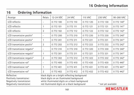
16 Ordering InformationAnzeige Relais 12-24 VDC 24 VAC 115 VAC 230 VAC 90-260 VAC
LCD reflectiv - 0 772 100 0 772 110 0 772 120 0 772 130 0 772 140*
LCD reflectiv 1 0 772 101 0 772 111 0 772 121 0 772 131 0 772 141*
LCD reflectiv 2 0 772 102 0 772 112 0 772 122 0 772 132 0 772 142*
LCD transmissive positiv* - 0 772 200 0 772 210 0 772 220 0 772 230 0 772 240*
LCD transmissive positiv* 1 0 772 201 0 772 211 0 772 221 0 772 231 0 772 241*
LCD transmissive positiv* 2 0 772 202 0 772 212 0 772 222 0 772 232 0 772 242*
LCD transmissive negativ* - 0 772 310 0 772 310 0 772 320 0 772 330 0 772 340*
LCD transmissive negativ* 1 0 772 301 0 772 311 0 772 321 0 772 331 0 772 341*
LCD transmissive negativ* 2 0 772 302 0 772 312 0 772 322 0 772 332 0 772 342*
LCD transmissive rot* - 0 772 400 0 772 410 0 772 430 0 772 430 0 772 440*
LCD transmissive rot* 1 0 772 401 0 772 411 0 772 431 0 772 431 0 772 441*
LCD transmissive rot* 2 0 772 402 0 772 412 0 772 432 0 772 432 0 772 442*
Reflective: black digits on a bright reflecting background Positively transmissive: black digits on an illuminated background Negatively transmissive: white illuminated digits on a black background Negatively transmissive: red illuminated digits on a black background * not yet available
16 Ordering Information