electronic rotary - applied avionics · pdf filethe electronic rotary is an 8-pin electronic...
TRANSCRIPT

The Electronic Rotary is an 8-pin electronic switching component developed as a part of the LOGIC Series by VIVISUN. The Electronic Rotary is customer configurable to replace a standard 2, 3, or 4 position rotary device. The Electronic Rotary component can be integrated into a traditional 4-pole switch housing, creating a LOGIC Body (LB), or can be included in a stand-alone LOGIC Module (LM) for use behind the panel. The Electronic Rotary can also be combined with electromechanical switches and other LOGIC Series components to create a custom configuration that uniquely addresses the designer’s specific functional requirements. The Electronic Rotary is designed and tested in accordance with MIL-PRF-22885 and DO-160.
Electronic Rotary
• 4 electrically separate control states• Configurable as a 2, 3 or 4 state rotary switch• Sink up to 2 amps with a resistive load• Advance to the next state on each high to low transition• Unit remains operational with power drop out up to 200 ms• All inputs are diode isolated and internally pulled up
High Capacity LOGIC Body as shown contains
Electronic Rotary, single switch pole and 4-pin
LOGIC component
LOGIC Module as shown contains
Electronic Rotary and 4-pin LOGIC components
Data Sheet: DS-ER1-11
LO G I C C o m p o n e n t Te c h n o l o g y
E L E C T R O N I C R O T A R YE L E C T R O N I C S W I T C H I N G
www.appliedavionics.com

Electronic Rotary
The Electronic Rotary component provides the ability to use a single illuminated pushbutton switch to cycle through multiple latched states either from successive switch closures or from a remote source. This enhances the options available, such as the capability to cycle through multiple communication systems, navigations systems, audio channels or video channels.
Benefits: The LOGIC Series Electronic Rotary functionally allows the ability to:
• Advance to the next state on each high to low transition of the increment input,
• Hold an existing latch state until either the next increment input or a reset occurs,
• Sink up to 2 amps with a resistive load,• Reset from an external input,• Initiate external override with the reset input, and• Maintain operational status with power drop out up to 200 ms.
How it works: The LOGIC Series Electronic Rotary eliminates the need to use multiple components or complex software to cycle through progressive states. Each unit is capable of 2, 3 or 4 latched states, and the designer determines the configuration by routing the next highest output back to the reset input.
A functional block diagram of the Electronic Rotary is illustrated in Figure 1. Refer to Table 1 for additional details on the operating parameters. A Signal Description and Truth Table is listed in Table 2 and Table 3.
Applications: In addition to the technical and qualification information on the following pages, typical applications for the Electronic Rotary are shown in the Application Examples of this brochure.
Compatibility: The LOGIC Series Electronic Rotary is compatible with a wide range of proven VIVISUN products, including:
• Indicators, switches and modules,• 3/4” LED caps and 1” x 1.2” LR3 LED caps,• 95 Series incandescent caps, and• the Quik-Connect™ solderless termination system (see Table 4).
VIVISUN LOGIC Series Overview: The Electronic Rotary is one of VIVISUN’s LOGIC Series electronic components designed to enhance avionics design flexibility. The Electronic Rotary can be inserted into either a) a High-Capacity LOGIC Body (LB), based on a standard 4-pole switch body with an illuminated lens cap, or b) a stand-alone behind-the-panel electronic LOGIC Module (LM). The innovative LOGIC Series was developed to simplify operator interface and circuit complexity by providing the ability to internally integrate multiple combinations of LOGIC Series components into a single envelope, including functionality such as:
• Switch poles (LOGIC Body only),• Electronic switching,• Electronic sensing and detecting, and• Logic/interface devices.
A single 8-pin LOGIC Series component like the Electronic Rotary can be combined with up to two additional 4-pin LOGIC Series components (LOGIC Module or LOGIC Body) or can be combined with an additional 8-pin component (LOGIC Module only) to bring a customized solution to your application. See Table 6 and How to Order for a complete description of the various configurations.
Table 1: Operating Parameters
Description Parameters
Operating Parameters
Maximum Operating Voltage +32 VDC
Nominal Operating Voltage +28 VDC
Minimum Operating Voltage +18 VDC
Power Supply Input Current 5 mA maximum
Reset From Power Loss 5 second maximum @ +25°C
Input Parameters at 25°C
/INCREMENT 50 ms
/RESET 80 ms
Timing /INC to output 100 ms maximum
High Level Input Voltage ( VIH ) 10 VDC minimum
Low Level Input Voltage ( VIL ) 1.2 VDC maximum
Low Level Input Current ( IIL ) 1 mA maximum
Note: All signal inputs are diode isolated
Output Load Capacity
Resistive 2.0 A
Motor 1.0 A
Lamp 0.8 A
lnductive 0.8 A
Operational Life 500,000 cycles at rated loads
Temperature
Operating -55°C to +85°C
Non-Operating -55°C to +85°C
Figure 1: Block Diagram
Logic Input Circuit: Provides a reliable diode isolated, buffered and debounced input interface. The inputs are internally pulled up to approximately 18V. This provides simple reliable operation with either external switches or open drain drivers.
Latch Circuitry: Proven reliable counter decoder that holds the current state until command to increment or reset.
Logic Output Circuitry: Provides ground switched open drain output drivers that are both fused and surge protected.
Power Supply: Efficient internal regulated supply that allows the unit to operate reliably on less than 5 mA.
ER-2
O V E R V I E WE L E C T R O N I C R O T A R Y

Table 2: Electronic Rotary Signal Description
Table 3: Electronic Rotary Truth Table
Inputs Outputs/RESET /INCREMENT /Q1 /Q2 /Q3 /Q4
H H L Next output, transistions from high impedence (open drain) to ground when state is active
L X Output is ground
High lmpedance
(Open Drain)
High lmpedance
(Open Drain)
High lmpedance
(Open Drain)
X = Input has no effect on output (“Don’t care”) condition. Note: Only one output is active at any one time.
Signal Name
Quik-Connect™ Pin* Number Logic Function Comments
/RESET J1 Input Low-Resets to state1 with /Q1 latched low when held low
/INCREMENT J3 High to low transition advances the unit to the next state
Increment input at state 4 will return the unit to state 1
+28 VDC J4 Power
GROUND K1 Ground Cont. Ground Req’d
/Q1 K2Output: High lmpedance
(Open Drain) Becomes ground when state is active
/Q2 K3Output: Default=High lmpedance
(Open Drain) Becomes ground when state is active
/Q3 K4Output: Default=High lmpedance
(Open Drain) Becomes ground when state is active
/Q4 J2Output: Default=High lmpedance
(Open Drain) Becomes ground when state is active
* Pin-out will change if two 8-pin components are configured in a LOGIC Module.
Table 5: Electronic Rotary (8-pin Component)
Table 4: Connector Plug
ER1
Pins* High Capacity LOGIC Body LOGIC Module Connector
PlugA, B, C, D, F, G Lamp Circuits N/A
P/N 18-440
H1-H4, L1-L4Switch Contacts
4-Pin LOGIC Series Contacts
J1-J4, K1-K4 Electronic Rotary Contacts (assuming a single 8-pin component)
* Pin-out will change if two 8-pin components are configured in a LOGIC Module.
Online Part Configuration
www.appliedavionics.com
The easy-to-use VIVISUN Configurator will ensure proper placement of all LOGIC Series components and assist with full part numbering.
Visit us online today at www.appliedavionics.com.
Table 6: LOGIC Series Overview
The Electronic Rotary may be used in the following packaging options:
The LOGIC Body (LB) expands the capabilities of a standard pushbutton switch or indicator by utilizing the 8-pin Electronic Rotary internally in 6 distinct combinations of electromechanical switches, LOGIC Series devices, and “open” spacers. The Electronic Rotary is compatible with the High Capacity LOGIC Body (based on a standard 4-pole housing).
The LOGIC Module (LM) is a stand alone behind-the-panel module that utilizes the 8-pin Electronic Rotary in 4 distinct combinations of LOGIC components and “open” spacers to provide functionality external to a standard switch envelope. The LOGIC Module may be wired directly into the harness or may mount in a bracket or rail.
For complete descriptions of the combinations see How To Order, LOGIC Body Configuration Guide (Data Sheet DS-LB-13) and the LOGIC Module Configuration Guide (Data Sheet DS-LM-13).
Component Types
{SW} Switch PolesHigh reliability
MIL-PRF-8805/101 snap action switches. Gold contacts
(5 or 7) are required when combining with an
8-pin module. Single Break, Silver 1, Gold 5
Double Break, Silver 3, Gold 7
{8-Pin} ComponentsElectronic components, such as electronic latching, edge detectors, electronic rotary,
and defined logic.
{4-Pin} ComponentsElectronic components, such as solid state relays
and diode packs.
(0) Open Module“Open” spacer for
unoccupied pole positions. No termination pins.
See www.appliedavionics.com for all current LOGIC Series component offerings.
LOGIC ModuleHigh Capacity
LOGIC Body
ER-3
O V E R V I E WE L E C T R O N I C R O T A R Y
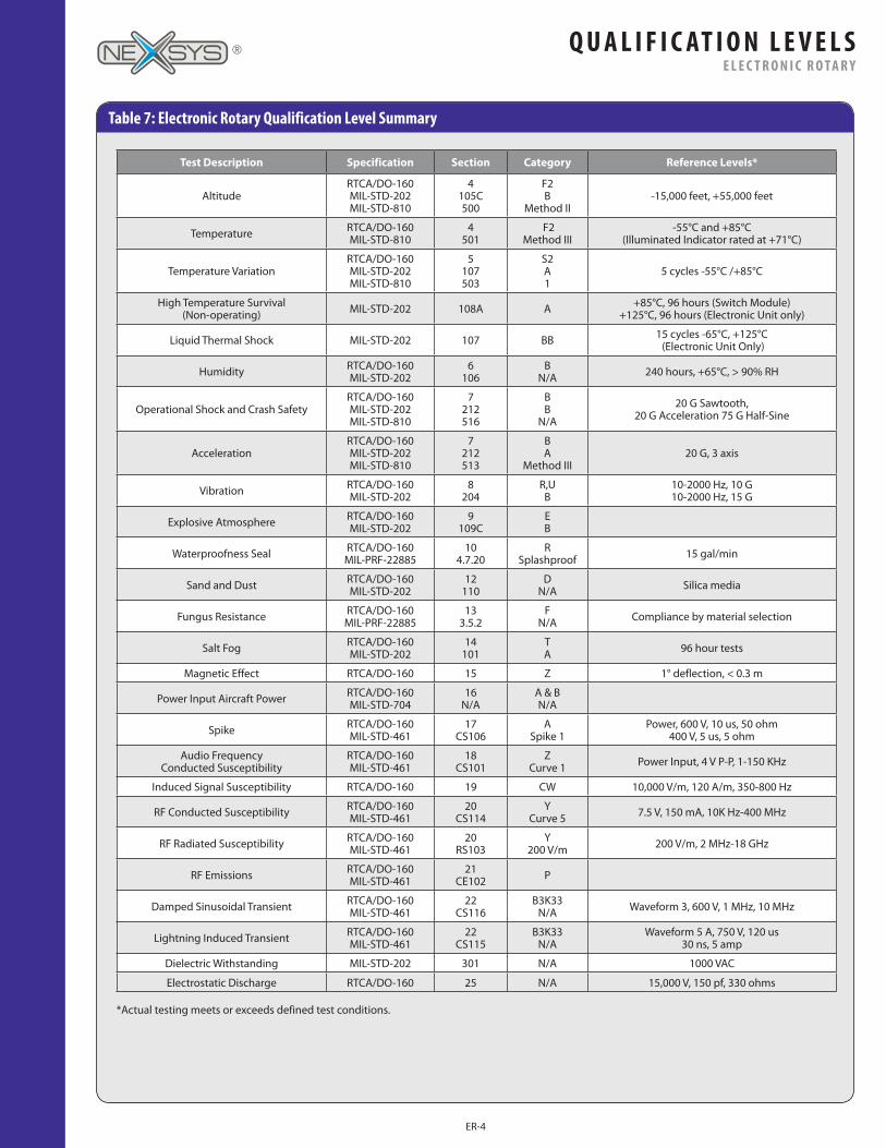
Test Description Specification Section Category Reference Levels*
AltitudeRTCA/DO-160 MIL-STD-202 MIL-STD-810
4 105C 500
F2 B
Method II-15,000 feet, +55,000 feet
Temperature RTCA/DO-160 MIL-STD-810
4 501
F2 Method III
-55°C and +85°C (Illuminated Indicator rated at +71°C)
Temperature VariationRTCA/DO-160 MIL-STD-202 MIL-STD-810
5 107 503
S2 A 1
5 cycles -55°C /+85°C
High Temperature Survival (Non-operating) MIL-STD-202 108A A +85°C, 96 hours (Switch Module)
+125°C, 96 hours (Electronic Unit only)
Liquid Thermal Shock MIL-STD-202 107 BB 15 cycles -65°C, +125°C (Electronic Unit Only)
Humidity RTCA/DO-160 MIL-STD-202
6 106
B N/A 240 hours, +65°C, > 90% RH
Operational Shock and Crash SafetyRTCA/DO-160 MIL-STD-202 MIL-STD-810
7 212 516
B B
N/A
20 G Sawtooth, 20 G Acceleration 75 G Half-Sine
AccelerationRTCA/DO-160 MIL-STD-202 MIL-STD-810
7 212 513
B A
Method III20 G, 3 axis
Vibration RTCA/DO-160 MIL-STD-202
8 204
R,U B
10-2000 Hz, 10 G 10-2000 Hz, 15 G
Explosive Atmosphere RTCA/DO-160 MIL-STD-202
9 109C
E B
Waterproofness Seal RTCA/DO-160 MIL-PRF-22885
10 4.7.20
R Splashproof 15 gal/min
Sand and Dust RTCA/DO-160 MIL-STD-202
12 110
D N/A Silica media
Fungus Resistance RTCA/DO-160 MIL-PRF-22885
13 3.5.2
F N/A Compliance by material selection
Salt Fog RTCA/DO-160 MIL-STD-202
14 101
T A 96 hour tests
Magnetic Effect RTCA/DO-160 15 Z 1° deflection, < 0.3 m
Power Input Aircraft Power RTCA/DO-160 MIL-STD-704
16 N/A
A & B N/A
Spike RTCA/DO-160 MIL-STD-461
17 CS106
A Spike 1
Power, 600 V, 10 us, 50 ohm 400 V, 5 us, 5 ohm
Audio Frequency Conducted Susceptibility
RTCA/DO-160 MIL-STD-461
18 CS101
Z Curve 1 Power Input, 4 V P-P, 1-150 KHz
Induced Signal Susceptibility RTCA/DO-160 19 CW 10,000 V/m, 120 A/m, 350-800 Hz
RF Conducted Susceptibility RTCA/DO-160 MIL-STD-461
20 CS114
Y Curve 5 7.5 V, 150 mA, 10K Hz-400 MHz
RF Radiated Susceptibility RTCA/DO-160 MIL-STD-461
20 RS103
Y 200 V/m 200 V/m, 2 MHz-18 GHz
RF Emissions RTCA/DO-160 MIL-STD-461
21 CE102 P
Damped Sinusoidal Transient RTCA/DO-160 MIL-STD-461
22 CS116
B3K33 N/A Waveform 3, 600 V, 1 MHz, 10 MHz
Lightning Induced Transient RTCA/DO-160 MIL-STD-461
22 CS115
B3K33 N/A
Waveform 5 A, 750 V, 120 us 30 ns, 5 amp
Dielectric Withstanding MIL-STD-202 301 N/A 1000 VAC
Electrostatic Discharge RTCA/DO-160 25 N/A 15,000 V, 150 pf, 330 ohms
*Actual testing meets or exceeds defined test conditions.
Table 7: Electronic Rotary Qualification Level Summary
ER-4
Q U A L I F I C AT I O N L E V E L SE L E C T R O N I C R O T A R Y
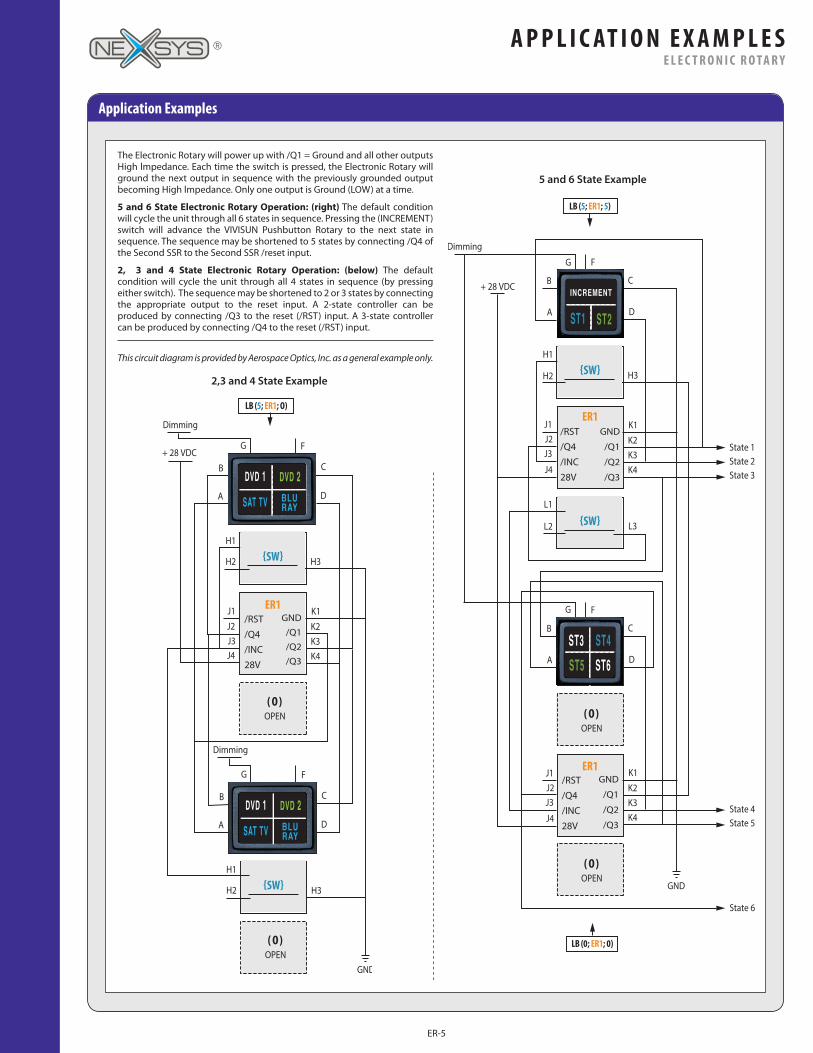
Application Examples
5 and 6 State Example
2,3 and 4 State Example
The Electronic Rotary will power up with /Q1 = Ground and all other outputs High lmpedance. Each time the switch is pressed, the Electronic Rotary will ground the next output in sequence with the previously grounded output becoming High lmpedance. Only one output is Ground (LOW) at a time.
5 and 6 State Electronic Rotary Operation: (right) The default condition will cycle the unit through all 6 states in sequence. Pressing the (INCREMENT) switch will advance the VIVISUN Pushbutton Rotary to the next state in sequence. The sequence may be shortened to 5 states by connecting /Q4 of the Second SSR to the Second SSR /reset input.
2, 3 and 4 State Electronic Rotary Operation: (below) The default condition will cycle the unit through all 4 states in sequence (by pressing either switch). The sequence may be shortened to 2 or 3 states by connecting the appropriate output to the reset input. A 2-state controller can be produced by connecting /Q3 to the reset (/RST) input. A 3-state controller can be produced by connecting /Q4 to the reset (/RST) input.
This circuit diagram is provided by Aerospace Optics, Inc. as a general example only.
ER-5
A P P L I C AT I O N E X A M P L E SE L E C T R O N I C R O T A R Y

How To Order
Configurations with 8-pin LOGIC Series ComponentsPosition Schematic Configuration Combinations
High Capacity LOGIC Body (LB) - with 8-pin Component
LB ( __ ; __ ; __ )LJ & KH
{SW} (5 or 7 only) {8-pin}{4-pin}O- Open Code
LB ( 0 ; {8-pin} ; 0 ) LB ( {SW} ; {8-pin} ; {SW} ) LB ( {SW} ; {8-pin} ; 0 )
LB ( {4-pin} ; {8-pin} ; 0 ) LB ( {4-pin} ; {8-pin} ; {4-pin} ) LB ( {SW} ; {8-pin} ; {4-pin} )
LOGIC Module (LM) - with Single 8-pin Component
LM ( 0 ; {8-pin} ; 0 ) LM ( {4-pin} ; {8-pin} ; 0 ) LM ( {4-pin} ; {8-pin} ; {4-pin} )
LOGIC Module (LM) - with Dual 8-Pin Components
Note: LOGIC Components have specific postion priorities inside of a LOGIC Body or LOGIC Module that must be determined using the online VIVISUN Configurator.
We’ve made the accurate configuration of VIVISUN products quick and easy.
Visit the VIVISUN Configurator at: www.appliedavionics.com/configuratorUsing the VIVISUN Configurator online will ensure that the entire LOGIC Body (including lens cap) or LOGIC Module is configured properly by assigning the selected options into the proper pole positions. You can e-mail complete part specifications and search part numbers. Registered users can also access a database of their previously configured VIVISUN parts.
For complete, manual part number configuration details on our LOGIC Body switches and indicators, refer to the LOGIC Body Configuration Guide (DS-LB-13); the datasheets for either the LED (3/4” square with LED lighting), the LR3 (1” x 1.2” rectangular with LED lighting) or the 95 series (3/4” square with incandescent lighting); and the datasheets for the desired LOGIC Series components.
For complete, manual part number configuration details on our behind-the-panel LOGIC Module solutions, refer to the LOGIC Module Configuration Guide (DS-LM-13) and the datasheets for the desired LOGIC Series components.
For up-to-date information on all available LOGIC Series components, visit www.appliedavionics.com
LM ( {8-pin} ; {8-pin} )
• Dual 8-pin configuration only available in LOGIC Module.
• Compatible with any two 8-pin LOGIC Series components.
• Note specific pin-out designations (H&J and K&L) in Position Schematic.
Full Sample Part Numbers Sample Descriptions Sample Circuit Diagrams Connector Plugs
LED-DM-11-ED-E18CY (JA3 INCREMENT; 6G1 ST1; 7T1 ST2)LB(7;ER1;0)
LED High Capacity LOGIC Body; including (1) double break gold switch, and (1) Electronic Latch, without a Connector Plug.
DM configurations require Connector Plug 18-440 to be ordered separately. Replacing DM with EM denotes a High Capacity LOGIC Body part number with a Connector Plug included.
LED-EM-17-DA-E199R (4A3 DVD 1; 5G3 DVD 2; 6T3 SAT, TV; 7T3 BLU, RAY)LB(SSR1H;ER1;DP2C)
LED High Capacity LOGIC Body; including (1) Solid State Relay, (1) Electronic Latch, and (1) Commercial Diode Pack, with a Connector Plug.
EM configurations denotes a High Capacity LOGIC Body part number with a Connector Plug included. Replacing EM with DM requires Connector Plug 18-440 to be ordered separately.
* Refer to applicable Data Sheets for the LED, LR3 and 95 Series for complete part number descriptions and options for the entire switch assembly.
© 2013 APPLIED AVIONICS, INC. DS-ER1-11 REV 2.1
Headquarters & USA Sales OfficeApplied Avionics, Inc. Telephone: 1-817-451-1141 3201 Sandy Lane Fax: 1-817-654-3405 Fort Worth, TX 76112 Toll-Free: 1-888-848-4786
E-mail: [email protected]
www.appliedavionics.com
International Sales OfficesSee ”Customer Support” at www.appliedavionics.com for a current listing and complete contact information for our international sales network, or e-mail the specific country address below:
Israel Brazil Spain Australia
United Kingdom Italy France Germany
[email protected] [email protected] [email protected] [email protected]
[email protected] [email protected] [email protected] [email protected]
ER-6
H O W T O O R D E RE L E C T R O N I C R O T A R Y