electronic security risks associated with use of wireless, point
TRANSCRIPT

Electronic Security Risks Associated With Use of Wireless, Point-to-Point Communications in
the Electric Power Industry
Allen Risley and Jeff Roberts Schweitzer Engineering Laboratories, Inc.
Revised edition released April 2003
Previously presented at the 56th Annual Conference for Protective Relay Engineers, April 2003
Originally presented at the DistribuTECH Conference, February 2003

1
ELECTRONIC SECURITY RISKS ASSOCIATED WITH USE OF WIRELESS,
POINT-TO-POINT COMMUNICATIONS IN THE ELECTRIC POWER INDUSTRY
Allen Risley and Jeff Roberts Schweitzer Engineering Laboratories, Inc.
Pullman, WA USA
ABSTRACT Wireless, point-to-point communications links are often used in the electric power industry to carry sensitive data like that associated with protection and control of the electric power grid. Many technologies, including IEEE 802.11 compliant wireless bridges and proprietary radio solutions, are used to implement these critical communications links. The recent discovery of severe security vulnerabilities in the encryption procedure used in the IEEE 802.11 wireless LAN standard has brought the risks associated with wireless communication links to light. In this paper, we discuss these security concerns and contrast the relative electronic security of radio technologies commonly used to implement point-to-point, long-distance communications links. Finally, we recommend defensive technologies that mitigate these risks for critical applications.
INTRODUCTION The electric power grid is a critical national infrastructure. Without the reliable delivery of electric power, many of society’s core functions rapidly deteriorate. Utilities take many steps to ensure a reliable power delivery system including installation of multiple power sources and multiple paths for delivering power. To reduce generation redundancy and costs, utilities interconnect their power grids. While these interconnections increase dependability, they also increase exposure and risk as any problem has the possibility of affecting a much larger geographical area. Ideally, the failure of any single device or apparatus does not interrupt power or place undo stress on the remaining apparatus of the grid.
The importance of providing fully redundant paths for energy flow is evident in the lessons learned in the 1965 Northeast US blackout and the 1996 blackouts in the West Coast of the US. The 1965 blackout started with the operation of a backup relay [1]. This single device operation started load redistribution that resulted in cascading relay operations and line outages. Over 30 million people were affected in this blackout. Similarly, the 1996 blackout started with relay operations that caused cascading line outages [2]. The 1996 blackout involved 13 states or provinces (Figure 1).

2
Figure 1 1996 West Coast US Blackout Affected Many High Voltage Grids
In each case, high system loading left little room for error in the power grid control system. In today’s environment, utilities must push their systems closer to their design limits to meet increasing load demands with limited infrastructure.
Localized, or even cascading effects can also be initiated by deliberate sabotage or misoperation of power system equipment by malicious individuals. The coordinated or random switching of breakers may lead to the destabilization of the grid. Furthermore, deliberate alteration of protection settings by a saboteur could result in severe damage to power lines, transformers, generation equipment, and other critical electric power assets in the event of a natural or deliberately induced fault.
The dramatic increase in the capabilities of relays and other Intelligent Electronic Devices (IEDs) has caused a corresponding increase in the level of electronic interconnectivity between such devices. A given control site (substation, generation facility, etc.) is likely to have electronic communication links for Supervisory Control and Data Acquisition (SCADA), real-time protection, engineering access, and Energy Management Systems (EMS). Furthermore, the industry drive to downsize and cut

3
operating expenses has led to an increase in the use of publicly accessible communications media in the implementation of these networks. Often, the cost of linking two physically separated IEDs is inversely proportional to the level of security risk incurred by the use of a given communication technology. For example, a 28 kbps connection from a given site to anywhere in the world can cost as little as $30 per month: $15 for the phone line and $15 for an account with a local Internet service provider. Such a connection can expose a site to millions of potentially hostile Internet users whenever the connection is online. A pair of direct, dialup modems can implement the same level of service for the additional cost of any incurred long-distance charges. The benefit of spending the extra money is the fact that such a connection does not expose the system to the hostile Internet environment. Such a solution does, however, have an intermediate level of risk due to the fact that anyone with a telephone line, a modem, and some motivation to probe the system can potentially break into critical electronic equipment. To “raise the bar” a bit, the connection can be implemented with a dedicated, leased line. A potential attacker must then compromise the phone company switching equipment or physically tap the local wire in order to break into the connected equipment. However, a 28 kbps leased-line implementation will almost certainly cost upwards of several hundred dollars per month with the final cost depending on the geographic distance between the connected points (among other determining factors). Finally, if the desire is to maximize electronic security at all costs, the connection can be made over a fully owned copper or fiber network. Such a network can be very expensive to build and to maintain.
For some applications it is often difficult, expensive, or impossible to implement some of the “standard” communications technologies mentioned above. One example of such an application is establishing electronic communication with a remote, pole-top IED. The installation costs associated with running a telephone line or some other wide-area networking medium to such a device could be prohibitive, especially if the IED is located far from a network access point (e.g., a telephone line demarcation box). This problem compounds when there are many such devices in a given system.
Difficult networking problems such as that mentioned above are often solved with wireless point-to-point radio technologies. The drive to cut system implementation and operation costs have made cost-effective wireless solutions a very attractive option for implementing network links between sites that are geographically close together and between which a relatively unobstructed transmission path exists. Solutions with ranges of 10 to 20 miles are common with directional antennas. Repeaters can be used to extend this range or to enable transmission over or around an obstruction. Radios that utilize the 902–928 MHz, 2.40–2.48 GHz, and 5.2–5.8 GHz unlicensed bands provide convenient solutions because they do not require FCC registration and corresponding operation fees. It is still common, however, to see licensed microwave radios in use for long distance, high bandwidth applications.
The use of wireless communications within the electric power industry poses some unique security concerns. These radios, if used to carry control traffic and/or engineering access, represent a potential path into the utility’s critical protection network. The fact that these technologies radiate their RF signals a long distance from the intended path of transmission, makes them susceptible to eavesdropping and data theft. Furthermore, the exposed transmission/reception antennas make these links susceptible to signal jamming, electronic intrusion, and injection of malicious traffic. It is very important to understand the relative security risks of a given wireless implementation. Such knowledge is essential for conducting an effective security risk-versus-cost analysis. The recent discovery of severe security flaws in the IEEE 802.11 wireless Local Area Networking

4
(LAN) protocol has thrust these issues into the spotlight. These flaws came to public knowledge due to the widespread popularity of the protocol in home and office LAN implementations. This technology is also in use in the electric power industry to implement point-to-point wireless network bridges. The standardized IEEE 802.11 protocol has been subject to much public scrutiny, and it has been shown to be completely insecure [3, 4]. Proprietary radio technologies, on the other hand, have not received this level of public scrutiny. Because of this, it is unclear precisely how secure such radios are.
In this paper, we will outline some of the electronic security risks associated with the use of wireless communications links. We will then describe the popular IEEE 802.11 wireless LAN protocol and discuss the weaknesses in the built-in encryption and authentication functions included in this protocol. The breakdown in security that has occurred due to the discovery of these weaknesses serves as an example of the risks associated with the use of unsecured wireless technologies in a communication architecture. Finally, we will contrast the security of IEEE 802.11 compliant devices with that offered by proprietary radio technologies and suggest techniques to mitigate the risk of electronic intrusion.
OVERVIEW OF WIRELESS SECURITY RISKS For fixed transmission media, like copper wires and optical fiber, the impulses that carry the signal information mainly are localized within the media. Furthermore, physical access to the network media is required in order to transmit or receive a signal over a fixed media network. This physical access usually comes in the form of a direct connection via a media termination plug (RJ-45, RJ-11, DB-9, etc.). Under normal operation, such a network will have a finite number of signal entry/reception points and a finite number of corresponding points at which an electronic security breach can potentially occur.
In contrast, wireless transmitters tend to spread a significant amount of signal energy away from the intended point of reception. The use of highly directional antennas can limit, but not eliminate, this energy dispersal. Figure 2 shows the transmitted energy (in dB) as a function of the angular position around the antenna for a directional, yagi antenna. Even with this high-quality, directional antenna, the 3 dB beamwidth is about 40 degrees. This beamwidth corresponds to a normal (perpendicular to the line of transmission) distance of 7.3 miles at a distance of 10 miles along the line of transmission. In other words, this antenna will paint a very large area with a significant percentage of its transmitted energy. This “leak” of radiation is further compounded by reflections from objects in the path of propagation.

5
Figure 2 Directional Antenna Radiation Pattern
The risks posed by this lack of signal containment are potentially significant. If attackers are able to demodulate and interpret the received signal, they may be able to recover sensitive information (passwords, network and system details, etc.). Furthermore, such an attack is passive in the sense that there is no way to detect this activity short of catching the individual in the act.
Another significant difference between fixed media links and wireless radio links is that the locations from which an attacker can potentially interact with your network are not limited to a known, finite number of points. In fact, if the attacker can direct transmitted energy from a point in the field to one of the receiving antennas on the link, then he/she is capable of affecting the functionality of your network from that point. Furthermore, the attacker can potentially communicate with the network to which the radio is attached if he/she is capable of transmitting a signal that can be properly demodulated by the receiver. Even if this is not feasible, proper communication over the radio link can be interrupted by a jamming signal consisting of a sufficient amount of bandpass noise within the communication frequency range of the target radio.
OVERVIEW OF THE IEEE 802.X STANDARDS The IEEE 802.X protocols are a family of communication standards for local and metropolitan area networking. The IEEE 802.2 standard defines the Logical Link Control (LLC) protocol that acts as a common data interface for the seven different 802.X Media Access Control (MAC) and Physical (PHY) Layer protocol definitions. The MAC/PHY specifications define how data are to be transmitted over a given physical transmission medium. Because different physical media require different transmission methods, a separate MAC/PHY specification must be defined for every desired transmission method. The LLC layer protocol simply acts as a common interface for all of the different MAC/PHY specifications. This intervening layer is required to make it possible for a high-level networking protocol suite (like TCP/IP) to seamlessly communicate over all of the transmission media for which an 802.X MAC/PHY layer is defined. The two MAC/PHY layers that we will be concerned about in this paper are the IEEE 802.3 CSMA/CD Access Method (Ethernet1) specification and the IEEE 802.11
1 Ethernet was invented by Xerox in the late 1970s and forms the basis for the IEEE 802.3 specification. The IEEE 802.3 protocol defines a generic Carrier Sense Multiple Access with Carrier Detect (CSMA/CD) protocol. The original Ethernet specification differs slightly from the IEEE 802.3 specification, but the name “Ethernet” is still commonly used to refer to both definitions.
6
Wireless LAN specification. How the IEEE 802.2, 802.3, and 802.11 protocols are related, in the context of this paper, is further explained below. Interactions between these protocols are important in the insecurities of the IEEE 802.11 wireless LAN standard.
A typical Ethernet LAN carries TCP/IP protocol packets over an acceptable fixed medium like twisted-pair copper wire, or optical fiber (CAT-5 twisted pair, copper wire with RJ-45 connectors is the most common). This is essentially accomplished by handing properly formatted IP packets to the hardware or software with behavior defined by the IEEE 802.2 LLC protocol. The LLC layer then puts the IP packet into the data region of a properly formatted LLC layer packet and hands the product to the MAC/PHY layer with behavior defined by the IEEE 802.3 Ethernet protocol.2 The packet is then placed on the wire for transmission on the LAN medium according to the IEEE 802.3 protocol. If we wish to use a wireless transmission scheme to transmit the original IP packet, the process is identical with the exception that the IEEE 802.2 LLC layer passes the LLC packet to the IEEE 802.11 wireless MAC/PHY protocol rather than to the IEEE 802.3 Ethernet protocol. The IEEE 802.X standards are written in a manner that makes the differences in transmission media transparent to all network protocols above the MAC layer.
OVERVIEW OF IEEE 802.11 The IEEE 802.11 protocol is designed to implement a LAN in which groups of computers can dynamically enter or exit the wireless network with relatively little difficulty. In keeping with this methodology, the physical layer is designed in a way that allows all compliant hosts to demodulate the digital signal without prior knowledge of network-specific settings. In other words, any host has access to all IEEE 802.11 MAC packets that are transmitted over the network. In normal operation, these packets will not be passed up to the LLC layer unless they are specifically addressed to the host’s MAC address, but it is very easy to place an IEEE 802.11 wireless network device in “promiscuous” mode. In this mode, the host device will send all packets up the network stack for further scrutiny regardless of whether or not they are actually addressed to the host.
There is a common misconception that spread spectrum modulation inherently provides a certain level of electronic security to a transmitted signal. The 802.1lb (the most common of the IEEE 802.11 variants) physical layer uses Direct Sequence Spread Spectrum (DS-SS) modulation to transmit the digital signal. This form of modulation spreads the signaling energy over a larger bandwidth (range of frequencies) than would otherwise be required to transmit the signal efficiently. This is useful from a noise immunity perspective because it provides a measure of protection from the effects of frequency-selective signal attenuation caused by reception of multiple, reflected versions of the signal at the receiver. For DS-SS modulation, a high frequency, periodic waveform is convolved with the original signal in order to obtain the desired frequency spreading. The form of this high-frequency signal is determined by a binary, pseudo-random noise (PN) sequence. The perception of security comes from the fact that the exact PN spreading sequence is required in order to demodulate the received signal. This fact is used in code division multiple access (CDMA) cellular phone systems to separate
2 This process assumes that the IEEE 802.3 CSMA/CD version of “Ethernet” is used and not the original, Xerox version.

7
and secure the conversations of individual users by assigning each user a unique PN sequence. In contrast, the IEEE 802.11 physical layer specification designates a single, 11-bit PN sequence to be used by all compliant devices. This allows all IEEE 802.11 compliant devices to demodulate the transmitted signal with no ambiguity at the physical layer. This approach results in global access to an IEEE 802.11 network, but provides absolutely no electronic security below the MAC layer. The designers of the IEEE 802.11 standard recognized the lack of security in the physical layer and added network separation and data security features in the MAC layer.
The Service Set Identifier (SSID) provides some degree of network separation. The SSID is a character string (similar to a password) that is transmitted in the MAC packet header and is intended to provide a mechanism for logical separation of wireless LANs. The SSID allows a network designer to assign groups of hosts to different wireless access points (AP).3 This is a convenient feature for environments in which there are multiple APs with overlapping service areas (the area in which a host is not out of range of the AP and can effectively communicate with the device). Because the SSID is transmitted in the MAC header in plain text (i.e., it is not encrypted or hidden), it provides almost no electronic security. It is, in fact, extremely easy to recover the SSID from packets captured from traffic between legitimate wireless LAN users (i.e., those with the correct SSID and permission to use the wireless network). Even worse, an AP will actually broadcast the SSID to all prospective clients unless it is configured otherwise (usually through a security setting in the device driver or configuration utility).
The IEEE 802.11 designers also included provisions for data encryption and authentication in order to provide what they thought were strong data security and network access control. Both functions are provided by the Wired Equivalent Privacy (WEP) procedures outlined in the standard. Encryption is provided to cryptographically scramble the data contents of the MAC packet prior to transmission. This is meant to keep sensitive data, like passwords and power system details, from being interpreted by malicious individuals. As outlined above, the MAC packets can still be intercepted but the data payload and network headers (above the MAC network layer) will, in theory, be incomprehensible due to the data scrambling provided by the encryption process. The encryption and decryption operations are a function of the original message data and a secret string of bits, known as the key. For symmetric encryption algorithms, like the RC-4 algorithm used in WEP, the encryption key and decryption keys are identical. The strength or security of the encryption process is determined by several factors, including:
�� the secrecy of the key �� the length of the key �� how often the key value is changed �� the cryptographic strength of the encryption algorithm
Because the encryption and decryption keys are identical for symmetric encryption algorithms, the theft or deduction of the key value by a malicious individual will compromise all communications encrypted by the recovered key. There are a few common methods for recovering a key value. The would-be attacker can simply steal the key value in some manner. If that option is not available, the attacker can attempt to guess the key value. The difficulty of such a guessing, or brute-force attack grows
3 An IEEE 802.11 access point can either be a traditional, short-range network access device or a long-range, point-to-point wireless bridge. Both devices communicate according to the IEEE 802.11 protocol and are, in the absence of proprietary security features, subject to the vulnerabilities outlined in this paper.

8
exponentially with the length of the key. The encryption process can be strengthened against key guessing attacks by periodically changing the key value. If the key value is ever guessed, then the attacker can only decrypt the data that were processed with the recovered key. Changing the key value on a periodic basis can significantly reduce the amount of data that is processed by a single key. Finally, the cryptographic strength of the encryption algorithm determines how difficult it is to compromise portions of the encrypted messages. If the algorithm is cryptographically sound, then it is extremely difficult to mathematically compromise the key value or message contents based on publicly available knowledge. Publicly available knowledge includes the encrypted message itself, known as ciphertext, and prior knowledge of the contents of the message, for example the statistics of English text or knowledge of the location and value of an encrypted header field. The encryption process also provides some degree of network access control or user authentication. The IEEE 802.11 standard specifies that if the incoming packet cannot be properly decrypted, then it must be dropped and ignored. This forces all hosts to know the value of the secret encryption key prior to being granted network access. Because the network designer can control the dissemination of the key value, he/she can control who is allowed access to the WEP-protected network. This assumption is clearly dependent on the integrity of the encryption key value. It will be shown in the following section that the WEP encryption algorithm is not cryptographically strong, and that the IEEE 802.11 standard provides virtually no electronic data security.
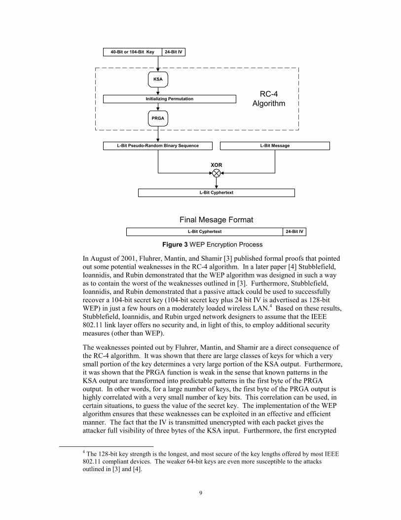
IEEE 802.11 WEP SECURITY FLAWS WEP is based on a two-part encryption algorithm called RC-4. Figure 3 shows how the RC-4 algorithm is used in WEP to encrypt the packet data prior to transmission. The first stage of the encryption process, known as the Key Scheduling Algorithm (KSA), takes a string of key bits as input and forms an output initialization string consisting of a pseudo-random permutation of a large number of integers. The second stage, known as the Pseudo-Random Generation Algorithm (PRGA), produces a pseudo-random bitstream of arbitrary length. The value of this string of bits is dependent on the initializing permutation produced by the KSA. It is important to point out that a given KSA input will always produce the same PRGA output. The designers of the IEEE 802.11 standard wanted the process of decrypting a single packet to be independent of all previous and future packets. Because of this requirement, the output of the PRGA function has to be reset at the beginning of every packet. If this were done without also changing the input to the KSA function, the encryption stream would be identical for every packet and the resulting encryption process would be trivially broken. Because of this, the input to the KSA function is a concatenation of a secret key (either 40 or 104 bits) with a 24-bit Initialization Vector (IV). By changing the IV on every packet, the WEP encryption process ensures that the probability of any two, randomly chosen packets being encrypted with the same PRGA output (known as an “IV collision”) is sufficiently low. For each L-bit packet, the concatenated key and IV serves as input to the RC-4 algorithm, which produces an L-bit (equal to the length of the packet) string of pseudo-random encryption bits. In order to perform the encryption operation, the encryption bit string is added modulo 2 (XOR) to the original contents of the packet. The IV that was employed during the encryption process is then concatenated with the resulting cyphertext to form the final message. The fact that the IV is appended to the cyphertext and transmitted unencrypted is a major contributor to the security weaknesses of the WEP encryption process. The details of these weaknesses are explained below.
9
KSA
PRGA
Initializing Permutation
L-Bit Pseudo-Random Binary Sequence L-Bit Message
L-Bit Cyphertext
XOR
40-Bit or 104-Bit Key 24-Bit IV
RC-4Algorithm
24-Bit IVL-Bit Cyphertext
Final Mesage Format
Figure 3 WEP Encryption Process
In August of 2001, Fluhrer, Mantin, and Shamir [3] published formal proofs that pointed out some potential weaknesses in the RC-4 algorithm. In a later paper [4] Stubblefield, Ioannidis, and Rubin demonstrated that the WEP algorithm was designed in such a way as to contain the worst of the weaknesses outlined in [3]. Furthermore, Stubblefield, Ioannidis, and Rubin demonstrated that a passive attack could be used to successfully recover a 104-bit secret key (104-bit secret key plus 24 bit IV is advertised as 128-bit WEP) in just a few hours on a moderately loaded wireless LAN.4 Based on these results, Stubblefield, Ioannidis, and Rubin urged network designers to assume that the IEEE 802.11 link layer offers no security and, in light of this, to employ additional security measures (other than WEP).
The weaknesses pointed out by Fluhrer, Mantin, and Shamir are a direct consequence of the RC-4 algorithm. It was shown that there are large classes of keys for which a very small portion of the key determines a very large portion of the KSA output. Furthermore, it was shown that the PRGA function is weak in the sense that known patterns in the KSA output are transformed into predictable patterns in the first byte of the PRGA output. In other words, for a large number of keys, the first byte of the PRGA output is highly correlated with a very small number of key bits. This correlation can be used, in certain situations, to guess the value of the secret key. The implementation of the WEP algorithm ensures that these weaknesses can be exploited in an effective and efficient manner. The fact that the IV is transmitted unencrypted with each packet gives the attacker full visibility of three bytes of the KSA input. Furthermore, the first encrypted
4 The 128-bit key strength is the longest, and most secure of the key lengths offered by most IEEE 802.11 compliant devices. The weaker 64-bit keys are even more susceptible to the attacks outlined in [3] and [4].

10
byte of almost every IEEE 802.11 packet is a known constant. This is a direct consequence of the fact that the first encrypted byte of an IEEE 802.11 packet is the Destination Service Access Point (DSAP) field of the LLC header, which has a value of 0xAA (hexadecimal) for all packets containing TCP/IP protocol data. This known value allows an attacker to recover the first byte of the PRGA output for virtually every packet by simply XORing the first byte of cyphertext with the value 0xAA. The attack against WEP is carried out by observing the IV values of each packet in search of the weak ones that result in the leak of information about the value of a particular secret key byte into the first byte of the PRGA output. This process can be carried out until all bytes of the secret key are recovered with sufficiently high probability. Most WEP implementations do not dynamically rotate or change the secret keys, so recovery of the secret key has the potential of compromising all network traffic for a very long period of time.
IMPLICATIONS OF IEEE 802.11 SECURITY FLAWS The IEEE 802.11 protocol has provided an inexpensive mechanism for wirelessly extending existing Ethernet LAN segments. This, coupled with the popularity of Ethernet in home and corporate networking environments, has fueled steadily increasing sales of IEEE 802.11 compliant devices. The widespread use of these wireless LAN devices and the electronic insecurities that the devices contain has not gone unnoticed in the hacking community. There are several automated software tools available for download on the Internet that can identify all IEEE 802.11 wireless APs that are within range, intercept the SSID and MAC address for each of these devices, identify whether or not WEP encryption is enabled on each device, and present all of the findings in a concise, easy to read format. These automated tools are being used to facilitate the systematic discovery of vulnerable wireless networks in an activity commonly referred to as wardriving.5 A wardriving setup usually consists of a laptop with a PCMCIA wireless network card, a high-gain antenna, and a suitable array of hacking software. An example of a typical wardriving setup is shown in Figure 4.
5 This term is a variation on the older term “wardialing” which is the act of systematically dialing telephone numbers in search of unprotected dialup modems.

11
Figure 4 Wardriving and Network Intrusion Equipment
One of the most popular wardriving software tools is pictured in Figure 5 (we have blacked out parts of the MAC addresses for privacy). This screenshot shows four wireless access points within range of the antenna. The display shows that these access points are on channels 4, 6, 7, and 11. An IEEE 802.11 compliant device can transmit on one of 14 different channels (the FCC limits this number to 11 within the US). The fact that there are multiple channels available in the standard does not provide any additional security or obscurity because the Network Stumbler software can automatically sweep all channels in search of active wireless APs. The intercepted SSID strings are also clearly displayed in the screenshot (eagleray, NP-ST, NP-T, and linksys) and, as explained earlier, provide no additional network security. Finally, this tool identifies which of the active APs have enabled WEP encryption and which have not.

12
Figure 5 Wireless Access Point Detection Software
If an AP is found that is protected by WEP encryption, but is “interesting” enough to warrant further investigation, the attacker can attempt to crack the WEP key. Several tools can passively capture normal wireless traffic on a target network and exploit the security flaws outlined above to automatically recover the WEP encryption key used to “secure” the transmitted data. One such tool is shown in Figure 6. These tools can successfully guess a WEP key by passively observing as few as 5 million network packets. Clearly, the amount of time that this process takes is dependent on the average amount of network traffic, but it is possible to recover a key in just a few hours on a moderately loaded network. Because the tools automate the cracking process, an attacker can simply leave the computer in range of the AP (i.e., in a parked car) and come back a few days later after software has broken the WEP key.
Figure 6 Wireless LAN WEP Encryption Key Cracking Software

13
Using the tools outlined above, an attacker can recover all of the parameters necessary to successfully associate with the IEEE 802.11 compliant AP. Changing the SSID and WEP settings of the local (on the attacker’s computer) wireless network interface card to match those of the target AP will allow the attacker to send traffic through the remote AP and onto the target network. Furthermore, the attacker can decode the contents of the traffic transmitted during normal network use. An attacker can employ a TCP/IP packet interception tool, commonly referred to as a sniffer, to either dump the packets to a file for later inspection or to examine the contents of interesting packets in real time. Figure 7 shows an example of a readily available sniffer.
Figure 7 TCP/IP Packet Interception Software (“Sniffer”)
The tool shows the current activity on the network in the upper window. Any of these packets can be selected and the contents will be displayed in the bottom window, interpreted as both hexadecimal (left) and ASCII text (right). The captured traffic may include information that can aid in compromising the devices connected to the AP. An example is the transmission of a Telnet login session over a wireless point-to-point bridge. The Telnet protocol sends the username and password information in unencrypted, ASCII text which can be read directly from the contents of the captured packets. Armed with this information, the attacker is free to initiate his/her own Telnet session on the remote device. In the absence of additional security hurdles, like firewall or virtual private networking (VPN) devices, the attacker is free to send traffic of his/her choosing onto the network. This traffic could be IP address or port scanning traffic designed to glean additional information about the remote network behind the AP (see [5] for further details on hacking tools and techniques). It could also be malicious packets aimed at a single device. An example is malicious operation of a remote breaker through injection of packets onto a wireless SCADA link.

14
The use of IEEE 802.11 compliant wireless bridges to implement long distance, point-to-point links exposes a network to random discovery. The popularity of wardriving is increasing dramatically among the hacking community. Because of this, it is becoming more likely that an attacker will “accidentally” discover your IEEE 802.11 bridge APs. Furthermore, building walls and other enclosures that tend to limit the signal propagation range of more traditional APs (most APs are used to implement indoor, local wireless LANs) are not present around long distance bridge antennas. Because of this, the range from which a bridging device can be located can be quite high.
PROPRIETARY RADIO IMPLEMENTATIONS Proprietary radio solutions are not designed to be consistent with a published standard. In general, the modulation, coding, and data format details are unique to each manufacturer, and usually between different radio models designed by the same manufacturer. In general, two radios must match a huge number of parameters in order to decode each other’s signal. Examples of these parameters are modulation technology (single carrier M-QAM, differential phase shift keying, frequency shift keying, etc.), carrier frequency, synchronization technique, energy dispersal (scrambling) codes, error correction/detection codes, and a huge variety of data formatting options. Because of this, it is likely that a potential attacker would have to begin with a radio of the same make and model as the target radio in order to initiate an attack. This fact makes it extremely unlikely that a malicious individual will accidentally discover the presence of a proprietary radio signal. If, however, an attacker was motivated to launch a directed attack at our critical electric power infrastructure, a proprietary radio link may represent a potential point of entry.
There are two main technologies in use in point-to-point, long distance radio links: spread spectrum modulation in the unlicensed frequency bands, and various forms of single carrier modulation in the licensed frequency bands. Spread spectrum technologies (direct sequence as well as frequency hopping) offer higher immunity to jamming, but there are no inherent electronic security differences between these two approaches. This is primarily due to the observation that most direct sequence and frequency hopped spread spectrum radio implementations have a very limited number of spreading sequences to choose from (just enough to provide interference reduction options). Because of this, the spread spectrum radios do not, in general, offer better electronic security than the radios operating in the licensed frequency bands.
In our survey of point-to-point radio models in use in the electric power industry, we found that very few proprietary radio models directly support dedicated electronic security features in the form of strong encryption and/or authentication. Furthermore, the number proprietary, noncryptographic electronic security features vary greatly with individual radio models. An example of such a proprietary security feature is the use of “matched” radios for point-to-point radio links. In one such scheme a unique device identification (like a serial number) is assigned to each radio produced by the manufacturer. If matching is supported, each radio can be programmed to accept data from only one other radio (the radio on the other end of the point-to-point link). The identity of this radio is determined by the unique ID, which is transmitted in every packet.
15
In the absence of dedicated electronic security features, the security of a proprietary radio solution is largely determined by how difficult it is for an attacker, with a radio of identical make and model as the target, to match the configuration of the target radio. The number of “configurations,” from an electronic security perspective, is the number of unique, functional settings configurations that, if not matched, will not allow communication with the radio. For example, assume that a radio model supports two channels and a 4-bit network identification number. If no other settings can be used to keep two of these radios from communicating with each other, then this radio model has only 2 · 24 = 32 unique configurations.
DEFENSIVE RECOMMENDATIONS The popularity of wardriving techniques coupled with the sharp increase in wireless hacking incidents against IEEE 802.11 devices must be taken into account when implementing point-to-point links with IEEE 802.11 compliant wireless bridges. The proprietary add-ons and security improvements that some manufacturers have been adding to their IEEE 802.11 products are a step in the right direction but until the security flaws in the underlying protocol are fixed, additional security technology should be employed to mitigate the risks. Due to the limited connectivity of point-to-point links (only one active link should exist) it is very easy to employ a Virtual Private Networking (VPN) device at each end of the wireless connection. These devices provide a strongly encrypted and authenticated, secure tunnel between the two antennas. If properly configured, the VPN devices will drop all traffic that does not pass cryptographic authentication (i.e., was not sent by the radio on the other side of the wireless bridge). The term, “VPN”, is typically reserved for security devices that are compliant with the IPSec protocol. This protocol is designed to provide strong encryption and authentication to TCP/IP traffic. We can use these IPSec products (VPNs) to secure wireless LAN bridges because IEEE 802.11 was designed to carry TCP/IP traffic exclusively. Furthermore, this solution is attractive because the use of TCP/IP on the Internet has ensured that VPN products are widely available and relatively inexpensive.
As stated before, proprietary radio solutions offer more anonymity than IEEE 802.11 devices. In the absence of additional security technologies (encryption, authentication, proprietary security features, etc.), this anonymity can translate into a more secure link. However, we advise additional security measures for proprietary radio links that carry sensitive data or represent a portal into a critical private network. A cost versus risk analysis should be done to determine what level of security is required for a given radio link. This analysis requires an assessment of the relative security offered by existing, in-service radio models or for new installations, the relative security of available radio models. If you decide that the security offered by these radio models is inadequate for the given application, then we recommend purchasing and installing additional security devices. If the radio link carries TCP/IP data, then VPN devices can be employed on each end of the link. Similar encryption and authentication devices exist for more generic wide area network protocols. An example is the Cylink Link Encryptor for T3, T1, E1, RS-232, RS-449, HSSI, V.35, X.21, and EIA-530. Cylink also makes similar products for ATM, and Frame Relay.

16
REFERENCES [1] Federal Power Commission, Prevention of Power Failures: An Analysis and
Recommendations Pertaining to the Northeast Failure and the Reliability of U.S. Power Systems; a Report to the President, Volume I, Federal Power Commission, 1967.
[2] J. F. Dahme, “The Summer of Our Disconnects,” Proceedings of the 24th Annual Western Protective Relay Conference, October 21–23, 1997, Spokane, WA.
[3] S. Fluhrer, I. Mantin, and A. Shamir, “Weaknesses in the Key Scheduling Algorithm of RC4,” Eighth Annual Workshop on Selected Areas in Cryptography, August 2001.
[4] A. Stubblefield, J. Ioannidis, A. D. Rubin, “Using the Fluhrer, Mantin, and Shamir Attack to Break WEP,” AT&T Labs Technical Report TD-4ZCPZZ, August 21, 2001.
[5] P. Oman, A. Risley, J. Roberts, E. Schweitzer, “Attack and Defend Tools for Remotely Accessible Control and Protection Equipment in Electric Power Systems,” 55th Annual Conference for Protective Relay Engineers, Texas A&M University, April 9–11, 2002, College Station, TX.
BIOGRAPHIES Allen Risley is a Security Analyst at Schweitzer Engineering Laboratories in Pullman, WA. Prior to joining SEL, he worked at Advanced Hardware Architectures as a Senior Research Engineer specializing in information theory and forward error correction. He received his Master of Science degree in Electrical Engineering from Washington State University in 1998. He has presented papers at the 1998 Conference on Information Sciences and Systems, as well as the 2001 ISCTA conference. His work has been published in the Proceedings of the International Symposium on Information Theory and the IEEE Transactions on Communications.
Jeff Roberts is a Research Fellow at Schweitzer Engineering Laboratories in Pullman, WA. Prior to joining SEL he worked for Pacific Gas and Electric as a Relay Protection Engineer. He received his BSEE from Washington State University in 1985. Mr. Roberts holds 19 patents and has several other patent applications pending; he has written many papers in the areas of distance element design, sensitivity of distance and directional elements, directional element design, and analysis of event report data. He has delivered papers at the Western Protective Relay Conference, Texas A&M University, Georgia Tech, Monterrey Symposium on Electric Systems Protection, and the South African Conference on Power System Protection. He is a Senior Member of the IEEE and was recognized by the Spokane chapter of the IEEE as Engineer of the Year for 2001.
Copyright © SEL 2003 (All rights reserved)
Printed in USA 20030408