electronic step, call/reset and monostable relays ffie electronic step, call/reset and monostable...
TRANSCRIPT

13SЕRIES
Electronic step, call/reset and monostable relays
W/C Call and reset switches for bathrooms
Bathrooms lighting control
Bedroom light control
Living room light control
Office lighting control

FINDER reserves the right to alter characteristics at any time without notice. FINDER assumes no liability for damage to persons or property, caused as a result of the incorrect use or application of its products.

XI-2
017,
ww
w.fi
nder
net.c
om
3
K
13SERIES
13 SERIES Electronic step relays 10 - 16 A
13.81 - Electronic step relay - Rail mount - 1 Pole
13.91 - Electronic step relay and timing step relay Switch box mount - 1 Pole
• Fixed time (10 minutes) timing function selectable (13.91)
• Use with 3 or 4 wire connection, with automatic recognition by the relay
• Control input can be continuously applied• Longer mechanical and electrical life, and much
quieter than electromechanical step relays• “Zero crossing” load switching• Can be mounted behind blanking plates, as
widely used in residential wiring systems such as; BTicino: Axolute, Matix, Living and Magic, Gewiss: GW24, Vimar: Plana and Idea … (13.91)
• 35 mm rail (EN 60715) mount (13.81)• Cadmium free contact material
13.81/91Screw terminals
13.81 13.91
• 1 NO (SPST-NO)• 35 mm rail (EN 60715) mount• 17.5 mm wide
• 1 NO (SPST-NO)• Step relay and timing step
relay (10 minutes)• For mounting within
residential switch boxes
For outline drawing see page 12
Contact specification
Contact configuration 1 NO (SPST-NO) 1 NO (SPST-NO)
Rated current/Maximum peak current A 16/30 (120 - 5 ms) 10/20 (80 - 5 ms)
Rated voltage/ Maximum switching voltage V AC 230/— 230/—
Rated load AC1 VA 3700 2300
Rated load AC15 (230 V AC) VA 750 450
Nominal lamp rating:
230 V incandescent/halogen W 3000 1000
fluorescent tubes with electronic ballast W 1500 500
fluorescent tubes with electromechanical ballast W 1000 350
CFL W 600 300
230 V LED W 600 300
LV halogen or LED with electronic ballast W 600 300
LV halogen or LED with electromechanical ballast W 1500 500
Minimum switching load mW (V/mA) 1000 (10/10) 1000 (10/10)
Standard contact material AgSnO2 AgSnO2
Supply specification
Nominal voltage (UN) V AC (50/60 Hz) 230 230
V DC — —
Rated power V A (50 Hz)/W 3/1.2 2/1
Operating range AC (50 Hz) (0.8…1.1)UN (0.8…1.1)UN
DC — —
Technical data
Electrical life at rated load in AC1 cycles 100 · 103 100 · 103
Maximum impulse duration continuous continuous
Dielectric strength between: open contacts V AC 1000 1000
supply - contacts V AC — —
Ambient temperature range °C –10…+60 –10…+50
Protection category IP 20 IP 20
Approvals (according to type)

XI-2
017,
ww
w.fi
nder
net.c
om
4
K
13 SERIES Electronic step/monostable relays 16 A
13SERIES
13.01 - Electronic step/monostable relay Rail mount - 1 Pole
13.61 - Multifunction step/monostable relay with reset command - Rail mount 1 Pole
• Selectable Step or Monostable operation (13.01)• Multifunction (Step, Timing step, Monostable,
Light ON) (13.61)• Reset feature, for centralized off command
(13.61)• Set feature, for centralized on command
(13.61.0.024)• Control input can be continuously applied• Longer mechanical and electrical life, and much
quieter than electromechanical step relays• 12…24 V AC/DC and 110…240 V AC supply
versions (13.61)• Suitable for SELV applications and available
also for supply 12 and 24 V AC/DC (13.01)• “Zero-crossing” load switching (13.61)• 35 mm rail (EN 60715) mount• Cadmium free contact material
13.01/61
Screw terminals
13.01 13.61.0.024.0000 13.61.8.230.0000
• 1 CO (SPDT)• Step or monostable relay• 35 mm rail (EN 60715) mount• 35 mm wide
• 1 CO (SPDT)• Reset feature, for centralized
off command• Set feature, for centralized on
command• Multifunction:
- step relay - timing step relay
(30s…20min)- monostable relay - light on
• 35 mm rail (EN 60715) mount• 17.5 mm wide
• 1 NO (SPST-NO)• Reset feature, for centralized
off command• Multifunction:
- step relay - timing step relay
(30s…20min)- monostable relay - light on
• 35 mm rail (EN 60715) mount• 17.5 mm wide
For outline drawing see page 12
Contact specification
Contact configuration 1 CO (SPDT) 1 CO 1 NO
Rated current/Maximum peak current A 16/30 (120 A - 5 ms) 16/30 (120 A - 5 ms) 16/30 (120 A - 5 ms)
Rated voltage/ Maximum switching voltage V AC 250/400 250/400 250/400
Rated load AC1 VA 4000 4000 4000
Rated load AC15 (230 V AC) VA 750 750 750
Nominal lamp rating:
230 V incandescent/halogen W 2000 2000 3000
fluorescent tubes with electronic ballast W 1000 1000 1500
fluorescent tubes with electromechanical ballast W 750 750 1000
CFL W 400 400 600
230 V LED W 400 400 600
LV halogen or LED with electronic ballast W 400 400 600
LV halogen or LED with electromechanical ballast W 800 800 1500
Minimum switching load mW (V/mA) 1000 (10/10) 1000 (10/10) 1000 (10/10)
Standard contact material AgSnO2 AgSnO2 AgSnO2
Supply specification
Nominal voltage (UN) V AC (50/60 Hz) 110…125 230…240 — 110…240
V DC/AC (50/60 Hz) 12 24 12…24 —
Rated power AC/DC V A (50/60 Hz)/W 2.5/2.5 1/0.5 3.2/1
Operating range V AC (50 Hz) 90…130 184…253 — 90…264
V DC/AC (50 Hz) 10.8…13.2 20.6…33.6 10.2…26.4 —
Technical data
Electrical life at rated load in AC1 cycles 100 · 103 100 · 103 100 · 103
Maximum impulse duration continuous continuous continuous
Dielectric strength between: open contacts V AC 1000 1000 1000
supply - contacts V AC 4000 2000 2000
Ambient temperature range °C –10…+60 –10…+60 –10…+60
Protection category IP 20 IP 20 IP 20
Approvals (according to type)
XI-2
017,
ww
w.fi
nder
net.c
om
5
K
13SERIES
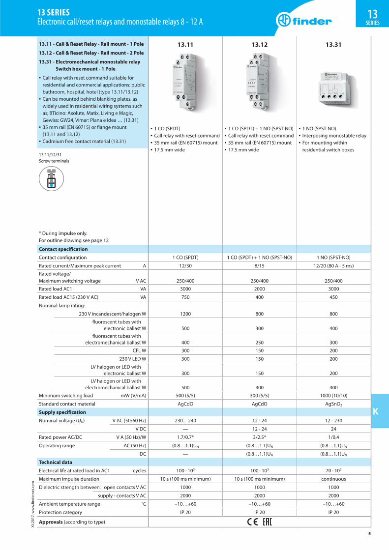
13 SERIES Electronic call/reset relays and monostable relays 8 - 12 A
13.11 - Call & Reset Relay - Rail mount - 1 Pole
13.12 - Call & Reset Relay - Rail mount - 2 Pole
13.31 - Electromechanical monostable relay Switch box mount - 1 Pole
• Call relay with reset command suitable for residential and commercial applications: public bathroom, hospital, hotel (type 13.11/13.12)
• Can be mounted behind blanking plates, as widely used in residential wiring systems such as; BTicino: Axolute, Matix, Living e Magic, Gewiss: GW24, Vimar: Plana e Idea … (13.31)
• 35 mm rail (EN 60715) or flange mount (13.11 and 13.12)
• Cadmium free contact material (13.31)
13.11/12/31Screw terminals
13.11 13.12 13.31
• 1 CO (SPDT)• Call relay with reset command• 35 mm rail (EN 60715) mount• 17.5 mm wide
• 1 CO (SPDT) + 1 NO (SPST-NO)• Call relay with reset command• 35 mm rail (EN 60715) mount• 17.5 mm wide
• 1 NO (SPST-NO)• Interposing monostable relay• For mounting within
residential switch boxes
* During impulse only.For outline drawing see page 12
Contact specification
Contact configuration 1 CO (SPDT) 1 CO (SPDT) + 1 NO (SPST-NO) 1 NO (SPST-NO)
Rated current/Maximum peak current A 12/30 8/15 12/20 (80 A - 5 ms)
Rated voltage/ Maximum switching voltage V AC 250/400 250/400 250/400
Rated load AC1 VA 3000 2000 3000
Rated load AC15 (230 V AC) VA 750 400 450
Nominal lamp rating:
230 V incandescent/halogen W 1200 800 800
fluorescent tubes with electronic ballast W 500 300 400
fluorescent tubes with electromechanical ballast W 400 250 300
CFL W 300 150 200
230 V LED W 300 150 200
LV halogen or LED with electronic ballast W 300 150 200
LV halogen or LED with electromechanical ballast W 500 300 400
Minimum switching load mW (V/mA) 500 (5/5) 300 (5/5) 1000 (10/10)
Standard contact material AgCdO AgCdO AgSnO2
Supply specification
Nominal voltage (UN) V AC (50/60 Hz) 230…240 12 - 24 12 - 230
V DC — 12 - 24 24
Rated power AC/DC V A (50 Hz)/W 1.7/0.7* 3/2.5* 1/0.4
Operating range AC (50 Hz) (0.8…1.1)UN (0.8…1.1)UN (0.8…1.1)UN
DC — (0.8…1.1)UN (0.8…1.1)UN
Technical data
Electrical life at rated load in AC1 cycles 100 · 103 100 · 103 70 · 103
Maximum impulse duration 10 s (100 ms minimum) 10 s (100 ms minimum) continuous
Dielectric strength between: open contacts V AC 1000 1000 1000
supply - contacts V AC 2000 2000 2000
Ambient temperature range °C –10…+60 –10…+60 –10…+60
Protection category IP 20 IP 20 IP 20
Approvals (according to type)

XI-2
017,
ww
w.fi
nder
net.c
om
6
K
13 SERIES Electronic step/monostable and call/reset
13SERIES
Ordering informationExample: 13 series, electronic step/monostable relay, 35 mm rail (EN 60715) mount, 1 CO (SPDT) 16 A contact, 230 V AC supply.
A B C D
1 3 . 0 1 . 8 . 2 3 0 . 0 0 0 0
Series
Type0 = Step/Monostable, 35 mm rail
(EN 60715) mount, 35 mm wide1 = Call & Reset relay, 35 mm rail
(EN 60715) mount, 17.5 mm wide3 = Monostable relay, switch box
mounting6 = Multifunction relay, 35 mm rail
(EN 60715) mount, 17.5 mm wide8 = Modular step relay, 35 mm rail
(EN 60715) mount, 17.5 mm wide9 = Step relay and timing step relay,
switch box mountingNo. of poles1 = 1 pole2 = 1 pole CO (SPDT) + 1 NO (SPST-NO)Supply version0 = AC (50/60 Hz)/DC8 = AC (50/60 Hz)9 = DCSupply voltage012 = 12 V AC/DC (13.01 and 13.12 only)012 = 12 V AC (13.31 only)024 = 24 V AC/DC (13.01 and 13.12 only)024 = 24 V DC (13.31 only)024 = 12…24 V AC/DC (13.61 only)125 = (110…125)V AC (13.01 only)230 = (230…240)V AC (13.01 and 13.11)230 = 110…240 V AC (13.61 only)230 = 230 V AC (13.31, 13.81 and 13.91)
A: Contact material0 = Standard4 = Standard AgSnO2 (only for 13.31)B: Contact circuit0 = Standard3 = Standard NO (only for 13.31)
Codes / Supply voltage13.01.0.012.0000 12 V AC/DC13.01.0.024.0000 24 V AC/DC13.01.8.125.0000 110…125 V AC13.01.8.230.0000 230…240 V AC13.11.8.230.0000 230…240 V AC13.12.0.012.0000 12 V AC/DC13.12.0.024.0000 24 V AC/DC13.31.8.012.4300 12 V AC13.31.9.024.4300 24 V DC13.31.8.230.4300 230 V AC13.61.8.230.0000 110…240 V AC13.61.0.024.0000 12…24 V AC/DC13.81.8.230.0000 230 V AC13.91.8.230.0000 230 V AC
Technical dataInsulation 13.01.8 13.01.0 13.11 - 13.12 13.31 - 13.61 13.81 - 13.91
Dielectric strength
between control circuit and supply V AC 4000 — — — —
between control circuit and contacts V AC 4000 4000 — — —
between R-S-A2 and contacts V AC — — 2000 — —
between supply and contacts V AC 4000 4000 — 2000 —
between open contacts V AC 1000 1000 1000 1000 1000
Other data 13.01 13.11 - 13.12 13.31 13.61 13.81 13.91
Power lost to the environment
without contact current W 2.2 — 0.4 1 1.2 0.7
with rated current W 3.5 1,5 1.6 1.8 2 1.8
Max cable lenght for push-button connection m 100 100 — 200 200 100
Max. no. of illuminated push-button (≤1mA) — — — 10* 15 12
Terminals 13.01 13.11 - 13.12 - 13.31 - 13.61 - 13.81 - 13.91
Max. wire size solid cable stranded cable solid cable stranded cable
mm2 1 x 6 / 2 x 4 1 x 6 / 2 x 2.5 1 x 6 / 2 x 4 1 x 4 / 2 x 2.5
AWG 1 x 10 / 2 x 12 1 x 10 / 2 x 14 1 x 10 / 2 x 12 1 x 12 / 2 x 14
Screw torque Nm 0.8 0.8
* For 8.230 version.

XI-2
017,
ww
w.fi
nder
net.c
om
7
K
13SERIES
13 SERIES Electronic step/monostable and call/reset
FunctionsType
13.01 MonostableOn closure of a switch between terminals (B2-B3) the output contact will close, and remain so, until the switch opens.
Step relay (bistable)After every impulse (B1-B2), the output contact changes state - alternately switching from open to closed and vice versa.
13.1113.12
(13.12 only)
Call and Reset relayOn momentary closure of the Set switch (S), the output contact closes. Only a momentary closure of the Reset switch (R) will open the output contact.
13.81 (RI) Step relayAfter every impulse, the output contact changes state - alternately switching from open to closed and vice versa.
13.91 (RI) Step relayAfter every impulse, the output contact changes state - alternately switching from open to closed and vice versa.
(IT) Timing step relayOn initial impulse the output contact closes and timing starts for the pre-set duration (fixed 10 min); On expiry of the time delay, the output contact opens.During the timing period it is possible to immediately open the contact with a further impulse.
Operating mode setup for type 13.91
RI → IT
a) Remove the supply voltageb) Press the control buttonc) Apply the supply to the relay, keeping the button closed.
After 3 second, the light will flash twice to indicate the selection of the “IT” function, or flash once for “RI” function.
IT → RI

XI-2
017,
ww
w.fi
nder
net.c
om
8
K
13 SERIES Electronic step/monostable and call/reset
13SERIES
FunctionsType Functions13.61.8.230 (RM) Monostable
On closure of a switch between terminal 3 and Line (or Neutral, in case of 3-wire connection) the output contact will close,and remain so, until the switch opens.
(IT) Timing step relayOn initial impulse the output contact closes and timing starts for the pre-set duration T; On expiry of the time delay, the output contact opens.During the timing period it is possible to immediately open the contact with a further impulse.Switch-off delay time: 30s…20min
(RI) Step relayAfter every impulse, the output contact changes state - alternately switching from open to closed and vice versa.
Light ONWith this function set - the output contact stays permanently closed.
13.61.0.024 (RM) MonostableOn closure of a switch between terminal 3 and Line (or Neutral, in case of 3-wire connection) the output contact will close,and remain so, until the switch opens.
(IT) Timing step relayOn initial impulse the output contact closes and timing starts for the pre-set duration T; On expiry of the time delay, the output contact opens.During the timing period it is possible to immediately open the contact with a further impulse.Switch-off delay time: 30s…20min
(RI) Step relayAfter every impulse, the output contact changes state - alternately switching from open to closed and vice versa.
Light ONWith this function set - the output contact stays permanently closed.

XI-2
017,
ww
w.fi
nder
net.c
om
9
K
13SERIES
13 SERIES Electronic step/monostable and call/reset
Wiring diagrams (13.01, 13.11, 13.12 and 13.31)
Type 13.01Step wiring diagram
Type 13.01Monostable wiring diagram
Red LED indication: Continuous = relay ON
Red LED indication: Continuous = relay ON
Type 13.11Call & reset relay
Type 13.12Call & reset relay
Reset
Set
Reset
Set
Type 13.31Connection
XI-2
017,
ww
w.fi
nder
net.c
om
10
K
13 SERIES Electronic step/monostable and call/reset
13SERIES
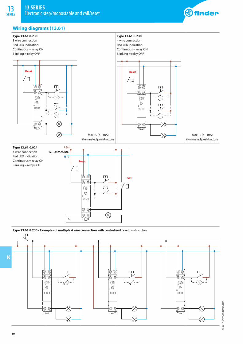
Wiring diagrams (13.61)Type 13.61.8.2303 wire connection Red LED indication: Continuous = relay ON Blinking = relay OFF
Type 13.61.8.2304 wire connection Red LED indication: Continuous = relay ON Blinking = relay OFF
Reset
Max 10 (≤ 1 mA) illuminated push buttons
Reset
Max 10 (≤ 1 mA) illuminated push buttons
Type 13.61.0.0244 wire connection Red LED indication: Continuous = relay ON Blinking = relay OFF
Reset
12…24 V AC/DC
Set
L (+)
N (-)
Type 13.61.8.230 - Examples of multiple 4 wire connection with centralized reset pushbutton

XI-2
017,
ww
w.fi
nder
net.c
om
11
K
13SERIES
13 SERIES Electronic step relays
Wiring diagrams (13.81 and 13.91)
Type 13.813 wire connection Red LED indication: Continuous = relay ON Blinking = relay OFF
Type 13.814 wire connection Red LED indication: Continuous = relay ON Blinking = relay OFF
L
N
Max 15 (≤ 1 mA) illuminated push buttons
Max 15 (≤ 1 mA) illuminated push buttons
Type 13.913 wire connection
Type 13.914 wire connection
Max 12 (≤ 1 mA) illuminated push buttons
Max 12 (≤ 1 mA) illuminated push buttons

XI-2
017,
ww
w.fi
nder
net.c
om
12
K
13 SERIES Electronic step relays
13SERIES
Outline drawings13.01Screw terminal
13.11Screw terminal
45 84
17.5
88.8 33.8
30.5
4.3 56.5
13.12Screw terminal
13.31/13.91Screw terminal
13.61Screw terminal
13.81 Screw terminal
XI-2
017,
ww
w.fi
nder
net.c
om
13
K
13SERIES
13 SERIES Electronic step relays
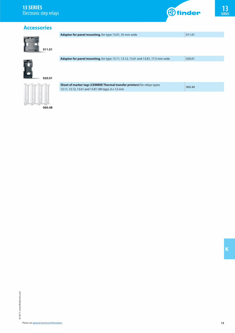
Accessories
011.01
Adaptor for panel mounting, for type 13.01, 35 mm wide 011.01
020.01
Adaptor for panel mounting, for type 13.11, 13.12, 13.61 and 13.81, 17.5 mm wide 020.01
060.48
Sheet of marker tags (CEMBRE Thermal transfer printers) for relays types 13.11, 13.12, 13.61 and 13.81 (48 tags), 6 x 12 mm
060.48
Please see general technical information
