electronic structure properties in the nematic phases of fese · yi liang, 1xianxin wu, and...
TRANSCRIPT

Electronic structure properties in the nematic phases of FeSe
Yi Liang,1 Xianxin Wu,1 and Jiangping Hu1, 2, 3, ∗
1 Institute of Physics, Chinese Academy of Sciences, Beijing 100190, China2Department of Physics, Purdue University, West Lafayette, Indiana 47907, USA
3Collaborative Innovation Center of Quantum Matter, Beijing, China(Dated: October 3, 2018)
We investigate the electronic structures of FeSe in the presence of different possible orders. We find thatonly ferro-orbital order (FO) and collinear antiferro-magnetism (C-AFM) can simultaneously induce splittingsat Γ and M. Bicollinear antiferro-magnetism (B-AFM) and spin-orbit coupling (SOC) have very similar bandstructure on Γ-M near the Fermi level. The temperature insensitive splitting at Γ and the temperature dependentsplitting at M observed in recent experiments can be explained by the d-wave bond nematic (dBN) order togetherwith SOC. The recent observed Dirac cones and their temperature (T ) dependence in FeSe thin films can alsobe well explained by the dBN order with band renormalization. Their thickness- and cobalt-doping- dependentbehaviors are the consequences of electron doping and reduction of Se height. All these suggest that the nematicorder in FeSe system is the dBN order.
PACS numbers: 74.20.Pg, 74.25.Jb, 74.70.Xa
The structurally simplest iron-based superconductor FeSesystem has attracted enormous attention due to its many fan-tastic properties. The FeSe bulk without any doping showssuperconductivity at Tc = 9 K and Tc can be significantlyenhanced to 38 K by applying pressure [1]. Surprisingly, theTc can reach 65 K in 1UC FeSe on SrTiO3 [2–5] and maybe over 100 K [6]. Furthermore, an robust zero-energy boundstate against magnetic field up to 8 T was observed at eachinterstitial iron impurity in superconducting Fe(Te,Se) and itbears all the characteristics of the Majorana bound state pro-posed for topological superconductors [7]. In addition, non-trivial topological states have been predicted to exist in Fe(Te,Se) and 1UC FeSe films on SrTiO3 substrates [8–10].
Recently, the nematic order in FeSe has attracted muchattention. Nematicity, defined as the breaking of tetrago-nal rotational symmetry, is a well-established experimentalfact in iron pnictides. Its origin is still highly debated be-tween magnetic orders [11–14] and orbital orders [15–18].The former is strongly supported by the facts that the or-thorhombic lattice distortion is always accompanied by thecollinear magnetic order in iron pnictides. However, the bulkFeSe shows an orthorhombic lattice distortion at Ts ∼ 90 Kwithout any evidence of magnetic phase transition. A bandsplitting at M is observed in FeSe below Tnem ∼ 120 Kby angle-resolved photoemission spectroscopy (ARPES) [19–25], which is taken as the direct signature of the nematicity.Very recently, the T-insensitive splitting at Γ and T-sensitivesplitting at M have been reported [20]. What is more, Diraccones have been discovered around M point in nematic phaseof FeSe thin films and cobalt doping can suppress the nematic-ity [24, 25]. So far, no strong evidence of anisotropy has beenobtained in FeSe as Ts < T < Tnem. As the splitting at highsymmetry points are highly confined by symmetry, it is possi-ble for us to seek the constraints on different orders in order toconsistently explain all experimental observations in the FeSenematic phase.
In this paper, we try to answer the above questions and un-
derstand the nematicity in FeSe system, which not only canhelp us to understand the origin of the fantastic properties ofFeSe, but also may shade much light on the superconductingmechanism of iron-based superconductors (FeSCs). We, withthe five-orbital tight-binding (TB) model for single unit-cell(UC) FeSe films, investigate the effects on the band struc-ture of eight possible orders in FeSe: FO order, antiferro-orbital (AFO) order, dBN order, charge order (CO), C-AFM,B-AFM, Neel antiferro-magnetism (N-AFM) and SOC. Wefind that only FO and C-AFM can simultaneously induce thesplittings at Γ and M, but in the C-AFM state, it is accom-panied by additional band folding. The splitting at Γ can beinduced in B-AFM and SOC. These two orders, near Fermienergy (EF ), have very similar band structure on Γ-M, butin B-AFM phase, two electron pockets must emerge at X .The splitting at M can arise in the presence of the dBN order.The left other orders can not produce the splittings observedin ARPES. The different T−dependence of the splitting at Γand M can be explained by the dBN order together with SOC.The recently observed Dirac cones and their T-dependence inFeSe thin films can also be well explained by the dBN orderwith band renormalization. The cobalt-doping- and thickness-dependent behaviors result from the electron doping, as wellas the reduction of Se height. All these suggest that the ne-matic order in FeSe system is dominated by the dBN order.
Effects of orders on electronic structure: To investigate theeffects of different orders, we start from the five-orbital TBmodel for 1UC FeSe films with the lattice parameters of bulkFeSe. The results have no qualitative difference with thosefrom the TB model for bulk. The Hamiltonian containing fiveFe 3d orbitals is given by,
H0 =∑
k∈BZ1,σ
ψ†σ(k)A0(k)ψσ(k), (1)
where ψ†σ(k) = [C†k1σ, C†k2σ, C
†k+Q3σ, C
†k+Q4σ, C
†k+Q5σ] ,
Q = (π, π), A0(k) is given in supplement materials and BZ1
arX
iv:1
510.
0422
0v1
[co
nd-m
at.s
upr-
con]
14
Oct
201
5

2
−2
−1
1
E−
EF
Γ Mx X Γ
ψ(k)ψ(k+Q)
EM1
EgΣ2
Σ1’
Σ2’
EM3
−π π
π
Mx′
Y
My
X
Mx
Y ′
My′
X′
Γ
Σ3 Σ4
FIG. 1: Band structure of 1UC FeSe film without any ordering (a)and its corresponding Fermi surface in the Brillouin zone (BZ) forFe lattice (b). The bands attributed to ψ(k) and ψ(k + Q) is plottedin red and blue respectively. The cyan dotted square and the greendashed rectangle are the BZ for C-AFM and B-AFM orders respec-tively.
denotes the Brillouin zone of one Fe lattice. Here, the natu-ral gauge is taken and the Fe 3d orbitals, for convenience, aredesignated as numbers, i.e., dxz → 1, dyz → 2, dx2−y2 →3, dxy → 4, dz2 → 5. The band structure of the above modelis shown in Fig. 1(a). The bands from ψ(k) are plotted inblue and those from ψ(k + Q) in red. The degeneracy at Γresults from the equivalence of dxz and dyz orbitals and nocoupling between them at Γ, which is protected by S4 sym-metry. Thus, there are two ways to break the degeneracy :one is to break the S4 symmetry on Fe sites as well as theC4 symmetry on Se sites; the other is to induce coupling be-tween dxz and dyz orbital at Γ. As for the two-fold degen-erate states (excluding spin degeneracy) on M-X, one is theψ(k) band and the other is ψ(k + Q) band. From the pointof view of symmetry, the band degeneracy on M-X is pro-tected by the symmetry of Υ = K{C2Y |Tx/y}, where K isthe conjugate operator and C2Y is the C2 rotation operatoralong the diagonal of Fe lattice and Tx/y is the translationin the x/y direction by the Fe-Fe distance. The anti-unitaryoperator Υ commutes with H0 and Υ2 = −1 on Υ-invariantM-X line, which infers that the bands on M-X are two-fold de-generate. Hence, the effective way to remove the degeneracyon M-X is to break Υ symmetry. Note that small band split-ting on M-X may alter the superconducting pairing symmetrydue to the change of the topology of electron Fermi pocketsfrom two intersecting ellipses into two separated concentricelectron pockets. On Γ-Mx/y line, dxz/yz and dxy orbitalsonly couple with each other and the other three orbitals hy-bridize. The three bands across EF on Γ-Mx, Σ2,Σ2′ andΣ1′ , consist of {Ck,2, Ck+Q,3, Ck+Q,5},{Ck,1, Ck+Q,4} and{Ck,4, Ck+Q,1} respectively. The band hybridization amongthese three bands can be induced by any coupling betweentheir components. Near the M point, the two bands fromψ(k),Σ2 and Σ4, form a Dirac cone. In the following, we discussthe effects of different orders and SOC on the band structure.
A. Ferro-orbital order: FO order, which is induced bytetragonal symmetry breaking, is characterized by the orbitalpolarization between dxz and dyz orbitals. The additional
−0.4
−0.2
0
0.2
E−
EF
M Γ Mx X Γ Y
(a) D I
D II
M Γ M X Γ Y
(b)
y y x
My Γ Mx
−0.2
0
E-E
F
0.2
−0.4
My Γ Mx
(c) (d)
FIG. 2: Band structure with FO order (a) and that for a twinnedsample (b), and the polarization-dependent bands in ARPES withrespect to Γ-Mx direction: (c) for even orbitals and (d) for odd or-bitals. ∆FO = 30 meV, to induce the observed splitting at Γ [20]. In(b), the bands attributed to domain D I and domain D II are plottedin red and blue respectively.
Hamiltonian term induced by this order can be written as,
hFO = ∆FO
∑k∈BZ1,σ
(nk,1,σ − nk,2,σ), (2)
where nk,α,σ = C+k,α,σCk,α,σ . Fig. 2(a) shows the band
structure with FO order. The most striking feature is the2∆FO gaps opened simultaneously at Γ and M points betweenthe dxz and dyz bands. The band splitting on Mx/y-X resultsfrom the symmetry breaking of Υ. Fig. 2(b) also provides theband structure of a twinned sample composed of two orthog-onal domains of which the order parameters are opposite, i.e.,∆DIIFO = −∆DI
FO. Since generally, the beam spot size of inci-dent light in ARPES is larger than the domain size, the bandstructure observed in ARPES is the combination of the bandsfor the two domains. As the two domains are connected by aC4 rotation, the splitted states become degenerate again andthe bands on My-Γ-Mx reappear symmetric. However, thesymmetry breaking can also been clearly observed in the po-larization dependent ARPES measurements, as shown in Fig.2(c) for the even orbitals and Fig. 2 (d) for the odd orbitals.
B. Antiferro-orbital order: AFO order is also characterizedby the orbital polarization between dxz and dyz orbitals butthe polarization changes alternatively with Fe sites. It can bedefined as εj,xz − εj,yz = ∆AFOe
iQ·Rj where εj,α is the on-site energy of orbital α on site j and Rj is the position of sitej. Thus the additional AFO Hamiltonian term, in momentumspace, can be written as
hAFO = ∆AFO
∑k∈BZ1,σ,α=1,2
sgn(α)C+k,α,σCk+Q,α,σ (3)

3
−0.4
−0.2
0
0.2E
−E F
ψ(k)ψ(k+Q)
My Γ Mx X Γ Y
(a) D ID II
My Γ Mx X Γ Y
(b)
FIG. 3: Band structure with dBN order (a) and that for a twinnedsample (b). |∆dBN | = 80 meV, the splitting observed at M in FeSethin films [23].
where sgn(α) equals 1 for α = 1 and -1 for α = 2.AFO order breaks the S4 symmetry on Fe site and inver-
sion symmetry, but preserves the C4 symmetry on Se sitesand translational symmetry. Thus, although this order inducesthe coupling between ψ(k) and ψ(k + Q) bands, there is nodegeneracy removal at Γ and M points except energy shifts fordxz/yz bands. The most distinct feature with AFO is the hy-bridization between Σ1′ and Σ2′ but no hybridization betweenΣ1′ and Σ2.
C. d-wave bond nematic order: The dBN order is character-ized by the hopping difference between x and y direction fordxz/yz orbitals [20, 26, 27]. It can originate from lattice or-thorhombic distortion or interatomic Coulomb repulsion [28].The additional Hamiltonian introduced by dBN order is givenby,
hdBN =∑
i,σ,α=1,2
∆dBN
8[C+i,α,σCi±ex,α,σ − C
+iασCi±eyασ]
=∑
k∈BZ1,σ,α=1,2
∆dBN
4(coskx − cosky)nk,α,σ. (4)
In dBN order, the S4, C4 and Υ symmetries are broken butthe glide symmetry is preserved. Therefore, the band degen-eracy on M-X is removed and ψ(k) and ψ(k + Q) bands arestill decoupled. As the dBN term vanishes on Γ − X/Y andachieves the maximum at Mx/y , an splitting of ∆dBN is in-duced at Mx/y but on splitting at Γ and X/Y points. Specifi-cally, in dBN order, the ψ(k) and ψ(k + Q) bands attributedto dxz/yz orbitals have energy shifts of −∆dBN
2 and ∆dBN
2 atMx respectively. These bands at My show the opposite shiftbehavior, which can be seen in Fig. 3(a). Considering thepossible domains in experiments, we also provide the bandstructure of a twinned system with dBN order in Fig. 3(b).
D. Charge order: Earlier theoretical study suggestedthat, in FeSCs, spin-density waves (SDW) can induce charge-density waves (CDW) with the modulation momentum,qCDW , double of wave vector of SDW, qSDW [29]. Thus,qCDW = (π, π) in FeTe. In FeAs system, besides qCDW =(0, 0), a CDW with qCDW = (π,±π) can also be caused atboundaries of SDW domains. Although no long range mag-netic order is observed in FeSe, it’s believed that it’s the result
My Γ Mx X Γ Y
ψ (k)ψ(k+Q)
C−AFM(b)
−0.4
−0.2
0
0.2
E−
E F
My Γ Mx X Γ Y
CO(a)
FIG. 4: Band structure with CO order (a) and that with C-AFM or-der (b). ∆CO = 40 meV. To induce a splitting of 30 meV at Γ,∆CAFM = 140 meV.
of competition of different magnetic fluctuations, which hasbeen demonstrated by neutron scattering and nuclear mag-netic resonance [30–33]. Thus, we can assume that a CDWwith qCDW = (π, π) exists in the normal state of FeSe. The(π, π) CDW is introduced by the difference of on-site energyon two sublattice of Fe, εAα − εBα = 2∆CDW . The additionalHamiltonian term is
hCDW = ∆CDW
∑k∈BZ1
C+k,α,σCk+Q,α,σ. (5)
The C4 and Υ symmetries are broken, but S4 symmetry ispreserved. Therefore, no anisotropy occurs in x, y directionand the band degeneracy on M-X is removed, as shown in Fig.4(a). The most distinct features are the splitting of EM3 states(labeled in Fig.1), which results from the coupling betweenCk,4,σ andCk+Q,4,σ . In addition, bands Σ1′and Σ2′ hybridizenear their intersection point.
E. Collinear AFM: AFM fluctuations have been found byneutron scattering and nuclear magnetic resonance in FeSe[30–33]. A DFT calculation also suggested close competi-tion between C-AFM and B-AFM in FeSe [34]. Thus in thefollowing, we consider the effects on band structure of threemagnetic orders: C-AFM, B-AFM and Neel AFM. Firstly,let’s discuss the effects of the most popular AFM order inFeSCs, C-AFM. It can be introduced by a spin polarized term,εj,α,↑ − εj,α,↓ = 2eiqCA·Rj∆CA(qCA = (π, 0)), which leadsto an additional Hamiltonian term,
hCA = ∆CA
∑k∈BZ1,α,σ
sgn(σ)C+k,α,σCk+qCA,α,σ. (6)
where sgn(σ) is the sign function, equals 1 for spin up and -1for spin down. Fig. 4(b) presents the band structure with C-AFM which is much different from that of the normal state.C-AFM doubles the unit cell and rotates it by 45 degrees,which reduces the volume of BZ for 2Fe unit cell by one halfand induces band folding and Fermi surface reconstruction.The normal-state bands located out of the magnetic BZ arefolded into the magnetic BZ with respect to its boundary. Thenormal-state bands around M are folded onto Γ and then newbands near EF appears around Γ. M point turns equivalentto Γ in C-AFM. The splitting at Γ point ∆Eg
∝ ∆2CA from
perturbation theory [35].

4
−0.4
−0.2
0
0.2
My Γ Mx X Γ Y
B−AFM(a)
E−
EF
My Γ Mx X Γ Y
SOC(b)
−0.4
−0.2
0
0.2
My Γ Mx X Γ Y
dBN+B−AFM(c)
My Γ Mx X Γ Y
dBN+SOC(d) D I
D II
E−
EF
FIG. 5: Band structures for a sample with SOC (a)and B-AFM order(b), and those for a twinned sample with coexistence of SOC anddBN order (c) and coexistence of B-AFM and dBN orders (d). In thefour cases, λ = 30 meV, ∆BA = 220 meV, ∆dBN = 80 meV, suchthat the splitting at Γ and M are about 30 and 80 meV respectively,the values observed in ARPES [20, 23].
F. Bicollinear AFM: Now we consider the effects of B-AFM on band structure and it can be modeled by εj,α,↑ −εj,α,↓ = eiqBA·Rj∆BA[1 + eiQ·Rj − i(1 − eiQ·Rj )] whereqBA = (π2 ,−
π2 ). The additional Hamiltonian term is
hBA = ∆BA
∑k∈BZ1,α,σ
(1− i
2C+
k,α,σCk+qBA,α,σ
+1 + i
2C+
k,α,σCk−qBA,α,σ)sgn(σ). (7)
In B-AFM, the S4, C4 and translational symmetries are bro-ken but Υ symmetry survives. Thus, the dxz/yz bands split atΓ point and bands on Mx/y-X are still degenerate, as shownin Fig. 5(a). The splitting ∆Eg = 0.36∆2
BAFM in our model[35]. In addition, Band Σ1′ hybridizes with Σ2,Σ2′ due tothe indirect hopping between C+
k,α,σ and Ck+Q,α,σ throughCk±qBA,α,σ . Another striking effect is the emergence of twoadditional electron pockets at X , which is induced by bandfolding. The magnetic primitive cell is a 2 × 1 (or 1 × 2)supercell of 2Fe unit cell. The magnetic BZ becomes a rect-angle and the rectangle in our case is shown with green dashline in Fig. 1(b). The normal-state bands out of magnetic BZare folded into it with respect to its boundary. In our cases,the bands around Y −My are folded onto Γ−X , which givesrise to the two additional electron pockets at X and the sym-metric band structures on M-X and Γ−Y with respect to theircenters.
G. Neel AFM: As for the N-AFM order, it can be mod-eled by, εi,α,↑ − εi,α,↓ = 2∆NAe
iQ·Ri . The additional termintroduced by the N-AFM order is,
hNA = ∆NA
∑k∈BZ1,α
(C+kα↑Ck+Qα↑−C+
kα↓Ck+Qα↓). (8)
TABLE I: Effects of different orders. ∆ denotes a splitting with theorder of ∆α and ∆2 for that with the order of ∆2
α, where ∆α is theorder parameter of order α. X means band spltting and X means noband splitting.
splitting hybridizationEg EM1 EM3 M-X Σ1′and Σ2 Σ1′and Σ2′
SOC ∆ X X X X XFO ∆ ∆ X X X X
AFO X X X X X XdBN X ∆ X X X XCO X X ∆ X X X
C-AFM ∆2 ∆2 X X X XB-AFM ∆2 X X X X XN-AFM X X ∆ X X X
In N-AFM phase, the magnetic unit cell is the same as that inthe normal state, so no band folding arises. The band structureis very similar with that of CO. The dxy bands splits at M, theband degeneracy on M-X is removed and bands Σ1′ and Σ2′
hybridize near their intersection point.H. SOC effects: Finally, we analyze the SOC effects on
electronic structure of FeSe. Due to the inversion symmetrywith respect to bond centers of nearest Fe-Fe, we consider anisotropic on-site SOC, hSOC = λ
∑i LiSi where
∑i sums
over the Fe sites. In supplement materials can find the de-tailed expression of hSOC in 3d−orbital space. Fig. 5(b) illus-trates the band structure with SOC. On-site SOC doesn’t breaktime reversal and space symmetries, only leads to Υ symmetrybreaking and hybridization of orbitals over the whole BZ1.Thus, the band structure still has C4 rotational and inversionsymmetries and the degenerate bands on M-X are splitted intotwo branches. Band Σ1′ hybridizes with bands Σ2,Σ2′ due tothe couplings of Ck,1/2,σ and Ck,3/4/5,σ . The splitting at Γis the result of the coupling of dxz and yz at Γ. The splitting∆Eg
= λ + a · λ2 where a is an model-dependent parameter[35].
Discussion: The effects of eight considered orders on bandstructure have been summarized in Table I. Four orders caninduce the splitting of Eg states and three ones can producethe splitting of EM1 states. Only FO and C-AFM orders si-multaneously break the degeneracies of Eg and EM1 states.C-AFM causes the normal-state bands around Γ and Mx/y
to fold onto each other. SOC and B-AFM have very similareffects, as shown in Table I. However, B-AFM induces thenormal-state bands around Γ-X and Y-My to fold onto eachother and then two additional electron pockets appear at X.Furthermore, a much larger order parameter is needed in B-AFM to produce the same splitting at Γ compared with that inSOC, since the splitting is an second order effect in B-AFM.It’s difficult to distinguish CO and N-AFM from the bandstructure, the measurement of charge distribution or magneticmoment on each Fe site is needed. In all the considered or-ders, SOC and B-AFM order can simultaneously generate hy-bridization between Σ1′ and Σ2/2′ . No order can produce hy-bridization between Σ1′ and Σ2 but no hybridization betweenΣ1′ and Σ2′ . While dBN coexists with SOC or B-AFM, the

5
band structures for twinned samples are very similar with thatfor a twinned sample with FO order, at least on Γ-M, as shownin Fig. 5(c,d). The difference is that, in the complex cases,the splittings at Γ and M can be different and only the split-ting at M is T -dependent while in FO, both are T -dependentand have the same values. The complex cases of dBN+SOCor dBN+B-AFM can almost explain the the ARPES obser-vation by Zhang et al. [20] except the little hybridization be-tween Σ1′ and Σ2′ . Considering the observed Dirac cones, thedBN+B-AFM case is excluded, because the dramatic breakingof Dirac cones by B-AFM, as shown in Fig. 5(c). This asser-tion is based on our following explanation of the origin of theobserved Dirac cones in ARPES.
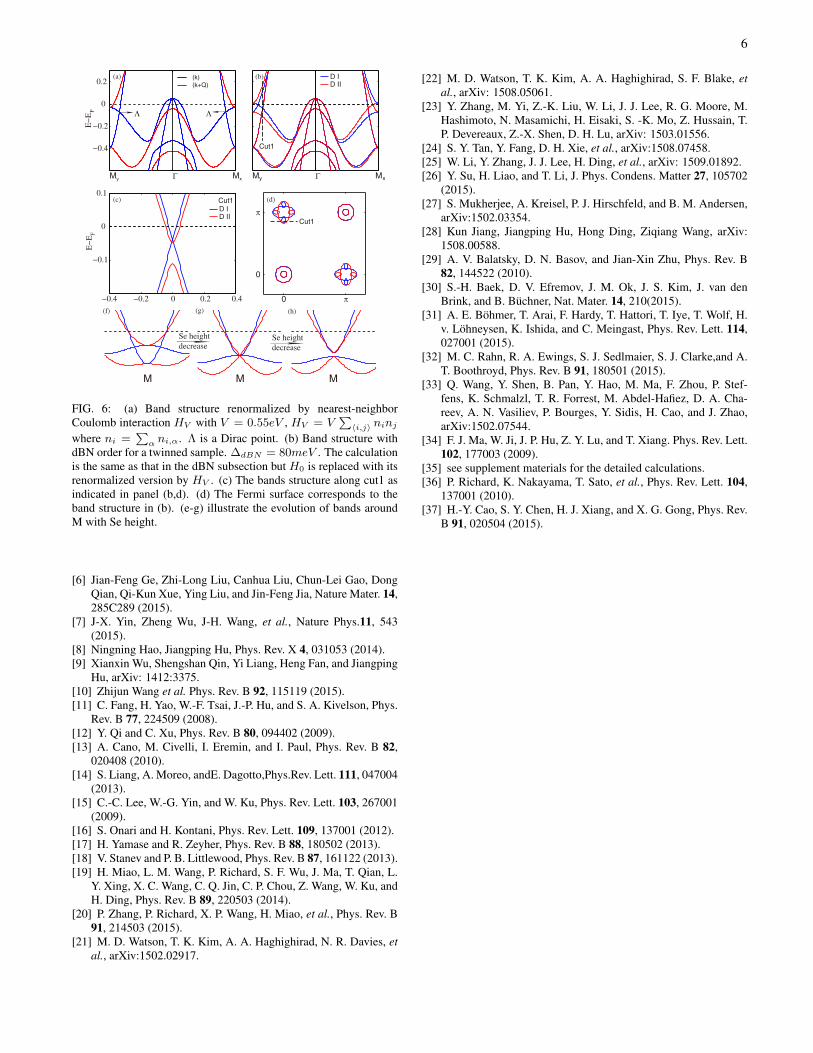
Very recently, in addition to the splitting at Γ and M, newARPES experiments observed four Dirac cones around M inFeSe thin films [24, 25]. Previously, Dirac cones have beenobserved in BaFe2As2 and they were revealed to originatefrom band folding in SDW phase [36]. Thus, the observedDirac cones are particularly intrigue because of the absence ofstatic magnetic order in FeSe. A recent DFT calculation hasalso predicted the existence of Dirac cones in FeSe but just inthe predicted “pair-checkerboard AFM” (P-AFM) phase [37].Due to band folding in P-AFM, the Dirac cone should be ob-served not only around M but also around Γ, which is incon-sistent with experiment results. In the following, we will showthat the observed Dirac cones can be explained by the dBNorder with band renormalization from interatomic Coulombinteraction. First, we consider the renormalization from in-teratomic Coulomb interaction [28]. The renormalized bandsare shown in Fig. 6(a), where two Dirac cones labeled as Λare near EF . Fig. 6(b) shows the bands with dBN order ina twinned system, where ∆dBN = 80 meV. We find that inone domain the Dirac cones on Γ-Mx are pushed up and thoseon Γ-My are pushed down and it is opposite in the second do-main. The Dirac cone can be clearly seen in Fig. 6(c), whichis consistent with experiment. The corresponding Fermi sur-faces are given in Fig. 6(d), where four Dirac cones appeararound M. They are consistent with those in experiment ex-cept the additional oval-shaped electron pockets at M. TheARPES results show that, as T is lowered below Tnem, thearea of electron pockets at M is reduced but little change oc-curs on hole pockets. Since the number of electrons should beconserved in general phase transition, some electron pocketsare not observed in the experiment. We argue that the missingpockets are just the two big elliptical electronic pockets at M.The reason that they are not observed in ARPES is probablyattributed to the photoemission matrix element effect.
With cobalt doping in multi-layer FeSe films, at first, thenematicity is suppressed significantly and then the Diraccones disappear at a higher doping [24]. The former effectattributes to the electron doping and the latter is the result ofreduction of Se height induced by cobalt dopant. The dBN or-der is induced by the quantum fluctuations from the proximityof the Van Hove singularity (EM1) to the Fermi level [28].The electron doping moves the Fermi level away from VanHove singularity, thus suppresses dBN order. This also ex-
plains the absence of nematic order in heavily electron doped1UC FeSe on SrTiO3 [24]. Upon cobalt doping, Se heightdecreases and the EM1 bands are pushed down and the EM3
bands are pushed up. The critical case is thatEM1 bands meetEM3 bands and the Dirac cones disappear, which is just thecase of 8% cobalt doping (see Fig. 6(f)). If the doping furtherincreases, EM1 and EM3 bands are inverted and an anticross-ing between Σ2′ and Σ4 happens, resulting in a gap at M point.In this case, the band is similar to the band of 1UC FeSe [8].Fig. 6(e-g) illustrates the bands around M with the decreaseof Se height.
Based on the explanation of the observed Dirac cone andthe effects of cobalt doping, two predictions can be made: 1)the dBN order in FeSe thin films may be enhanced with smallhole doping. 2) the Dirac cones can survive and just exhibit anenergy shift with dopants that can increase Se height or reduceFe-Fe distance.
The driving force of nematicity in FeSe system is still underdebate. Clear band splitting around M was discovered at thetemperature that is much higher than the structure transitiontemperature. Furthermore, the formation of C2 domain wallsshows no correlation with lattice strain pattern [25]. There-fore, the nematicity is unlikely related to lattice distortion.Recent calculations show that interatomic Coulomb interac-tion can induce the dBN order [28]. Thus, the nematicity inFeSe system may have a electronic origin.
Summary: We investigated the effects on the electronicstructure of eight possible orders in FeSe system. We foundthat only FO and C-AFM can simultaneously induce splittingsat Γ and M. B-AFM and SOC have very similar band struc-tures on Γ-M near EF . The T -insensitive splitting at Γ andthe T -dependent splitting at M can be explained by the dBNorder together with SOC. The recent observed Dirac conesand their temperature dependence in FeSe thin films can alsobe well explained by the dBN order with band renormaliza-tion. Their thickness- and cobalt-doping- dependent behav-iors are the consequences of electron doping and reduction ofSe height. All these suggest that the nematic order in FeSesystem is dominated by the dBN order, which is attributed toelectronic origin.
Acknowledgement: The work is supported by the Ministryof Science and Technology of China 973 program (Grant No.2012CV821400 and No. 2010CB922904), National ScienceFoundation of China (Grant No. NSFC-1190024, 11175248and 11104339), and the Strategic Priority Research Programof CAS (Grant No. XDB07000000).
∗ Electronic address: [email protected][1] S. Medvedev, T. M. McQueen, I. A. Troyan, T. Palasyuk, et al.,
Nat. Mater. 8, 630 (2009).[2] S. Tan, et al., Nature Mater. 12, 634–640 (2013).[3] S. He, et al., Nature Mater. 12, 605–610 (2013).[4] W-H. Zhang, et al., Chin. Phys. Lett. 31, 017401 (2014).[5] Q-Y. Wang, et al., Chin. Phys. Lett. 29, 037402 (2012).
6
−0.4
−0.2
0
0.2E
−E
F
My Γ Mx My Γ Mx
−0.4 −0.2 0 0.2 0.4
−0.1
0
0.1
E−
EF
0
0
π
π
Λ
Cut1
Cut1
(a) (b)
(c) (d)
(k)
(k+Q)
D ID II
M M M
(f) (g) (h)
Λ
D ID II
Se height
decreaseSe height
decrease
Cut1
FIG. 6: (a) Band structure renormalized by nearest-neighborCoulomb interaction HV with V = 0.55eV , HV = V
∑〈i,j〉 ninj
where ni =∑α ni,α. Λ is a Dirac point. (b) Band structure with
dBN order for a twinned sample. ∆dBN = 80meV . The calculationis the same as that in the dBN subsection but H0 is replaced with itsrenormalized version by HV . (c) The bands structure along cut1 asindicated in panel (b,d). (d) The Fermi surface corresponds to theband structure in (b). (e-g) illustrate the evolution of bands aroundM with Se height.
[6] Jian-Feng Ge, Zhi-Long Liu, Canhua Liu, Chun-Lei Gao, DongQian, Qi-Kun Xue, Ying Liu, and Jin-Feng Jia, Nature Mater. 14,285C289 (2015).
[7] J-X. Yin, Zheng Wu, J-H. Wang, et al., Nature Phys.11, 543(2015).
[8] Ningning Hao, Jiangping Hu, Phys. Rev. X 4, 031053 (2014).[9] Xianxin Wu, Shengshan Qin, Yi Liang, Heng Fan, and Jiangping
Hu, arXiv: 1412:3375.[10] Zhijun Wang et al. Phys. Rev. B 92, 115119 (2015).[11] C. Fang, H. Yao, W.-F. Tsai, J.-P. Hu, and S. A. Kivelson, Phys.
Rev. B 77, 224509 (2008).[12] Y. Qi and C. Xu, Phys. Rev. B 80, 094402 (2009).[13] A. Cano, M. Civelli, I. Eremin, and I. Paul, Phys. Rev. B 82,
020408 (2010).[14] S. Liang, A. Moreo, andE. Dagotto,Phys.Rev. Lett. 111, 047004
(2013).[15] C.-C. Lee, W.-G. Yin, and W. Ku, Phys. Rev. Lett. 103, 267001
(2009).[16] S. Onari and H. Kontani, Phys. Rev. Lett. 109, 137001 (2012).[17] H. Yamase and R. Zeyher, Phys. Rev. B 88, 180502 (2013).[18] V. Stanev and P. B. Littlewood, Phys. Rev. B 87, 161122 (2013).[19] H. Miao, L. M. Wang, P. Richard, S. F. Wu, J. Ma, T. Qian, L.
Y. Xing, X. C. Wang, C. Q. Jin, C. P. Chou, Z. Wang, W. Ku, andH. Ding, Phys. Rev. B 89, 220503 (2014).
[20] P. Zhang, P. Richard, X. P. Wang, H. Miao, et al., Phys. Rev. B91, 214503 (2015).
[21] M. D. Watson, T. K. Kim, A. A. Haghighirad, N. R. Davies, etal., arXiv:1502.02917.
[22] M. D. Watson, T. K. Kim, A. A. Haghighirad, S. F. Blake, etal., arXiv: 1508.05061.
[23] Y. Zhang, M. Yi, Z.-K. Liu, W. Li, J. J. Lee, R. G. Moore, M.Hashimoto, N. Masamichi, H. Eisaki, S. -K. Mo, Z. Hussain, T.P. Devereaux, Z.-X. Shen, D. H. Lu, arXiv: 1503.01556.
[24] S. Y. Tan, Y. Fang, D. H. Xie, et al., arXiv:1508.07458.[25] W. Li, Y. Zhang, J. J. Lee, H. Ding, et al., arXiv: 1509.01892.[26] Y. Su, H. Liao, and T. Li, J. Phys. Condens. Matter 27, 105702
(2015).[27] S. Mukherjee, A. Kreisel, P. J. Hirschfeld, and B. M. Andersen,
arXiv:1502.03354.[28] Kun Jiang, Jiangping Hu, Hong Ding, Ziqiang Wang, arXiv:
1508.00588.[29] A. V. Balatsky, D. N. Basov, and Jian-Xin Zhu, Phys. Rev. B
82, 144522 (2010).[30] S.-H. Baek, D. V. Efremov, J. M. Ok, J. S. Kim, J. van den
Brink, and B. Buchner, Nat. Mater. 14, 210(2015).[31] A. E. Bohmer, T. Arai, F. Hardy, T. Hattori, T. Iye, T. Wolf, H.
v. Lohneysen, K. Ishida, and C. Meingast, Phys. Rev. Lett. 114,027001 (2015).
[32] M. C. Rahn, R. A. Ewings, S. J. Sedlmaier, S. J. Clarke,and A.T. Boothroyd, Phys. Rev. B 91, 180501 (2015).
[33] Q. Wang, Y. Shen, B. Pan, Y. Hao, M. Ma, F. Zhou, P. Stef-fens, K. Schmalzl, T. R. Forrest, M. Abdel-Hafiez, D. A. Cha-reev, A. N. Vasiliev, P. Bourges, Y. Sidis, H. Cao, and J. Zhao,arXiv:1502.07544.
[34] F. J. Ma, W. Ji, J. P. Hu, Z. Y. Lu, and T. Xiang. Phys. Rev. Lett.102, 177003 (2009).
[35] see supplement materials for the detailed calculations.[36] P. Richard, K. Nakayama, T. Sato, et al., Phys. Rev. Lett. 104,
137001 (2010).[37] H.-Y. Cao, S. Y. Chen, H. J. Xiang, and X. G. Gong, Phys. Rev.
B 91, 020504 (2015).

7
Supplementary material for “Effects of possible ordered phase on electronic structure of FeSe”
TIGHT-BINDING MODEL
In our paper, the TB model H0 is obtained from the five-orbital TB fit of the DFT band structure for 1UC FeSe film with thelattice parameters of FeSe bulk, which is similar to the TB model for LaOFeAs given by Graser et al. except some additionalhopping terms [1]. The specific expressions are given to facilitate others’ use of it. H0 can be written as
H0 =∑
k∈BZ1,σ
ψ†σ(k)A0(k)ψσ(k), (S1)
where ψ†σ(k) = [C†k1σ, C†k2σ, C
†k+Q3σ, C
†k+Q4σ, C
†k+Q5σ] , Q = (π, π) and the matrix elements of A0(k) are in the following:
e11/22(k) = ε11/22 + 2t11x/ycoskx + 2t11
y/xcosky + 4t11xycoskxcosky + 2t11
xx/yycos2kx + 2t11yy/xxcos2ky
+4t11xyy/xxycoskxcos2ky + 4t11
xxy/xyycos2kxcosky + 4t11xxyycos2kxcos2ky,
e33/44/55(k) = ε33/44/55 + 2t33/44/55x (coskx + cosky) + 4t33/44/55
xy coskxcosky + 2t33/44/55xx (cos2kx + cos2ky)
+4t33/44/55xxy (coskxcos2ky + cos2kxcosky) + 4t33/44/55
xxyy cos2kxcos2ky,
e12(k) = −4t12xysinkxsinky − 4t12
xxy(sinkxsin2ky − sin2kxsinky)− 4t44xxyysin2kxsin2ky,
e13/23(k) = ±2it13y sinky/x ± 4it13
xycoskx/ysinky/x ± 2it13yysin2ky/x
±4it13xyycoskx/ysin2ky/x ± 4it13
xxycos2kx/ysinky/x,
e14/24(k) = 2it14x sinkx/y + 4it14
xysinkx/ycosky/x + 4it14xxysin2kx/ycosky/x
+2it14xxsin2kx/y + 4it14
xxyysin2kx/ycos2ky/x,
e15/25(k) = 2it15x sinky/x − 4it15
xycoskx/ysinky/x − 4it15xxyycos2kx/ysin2ky/x
+2it15yysin2ky/x + 4it15
xyycoskx/ysin2ky/x + 4it15xxycos2kx/ysinky/x,
e34(k) = 4t34xyy(sinkxsin2ky − sin2kxsinky),
e35(k) = 2t35x (coskx − cosky) + 4t35
xyy(coskxcos2ky − cos2kxcosky) + 2t35xx(cos2kx − cosky),
e45(k) = 4t45xysinkxsinky + 4t45
xxyysin2kxsinky.
TABLE S1: The on-site energy used for the DFT fit of the five-orbital TB model.εxz εyz εx2−y2 εxy εz2
0.050 0.050 -0.483 -0.035 -0.403
TABLE S2: The intraorbital hopping parameters used for the DFT fit of the five-orbital TB model.tmmi i=x y xy xx yy xxy xyy xxyym=1 -0.069 -0.317 0.227 0.002 -0.036 -0.019 0.014 0.024m=3 0.396 -0.070 -0.013 0.012m=4 0.061 0.085 0.002 -0.019 -0.024m=5 0.005 0.013 -0.014 0.006 -0.011
THE CALCULATION OF THE Γ SPLITTING IN C-AFM ORDER
C-AFM induces an additional Hamiltonian term,
hCA = ∆CA
∑k∈BZ1,α,σ
sgn(σ)C+k,α,σCk+qCA,α,σ. (S2)

8
TABLE S3: The intraorbital hopping parameters used for the DFT fit of the five-orbital TB model.tmni i=x xy xx yy xxy xyy xxyy
mn=12 0.103 -0.011 0.032mn=13 0.380 -0.089 -0.011 -0.018 0.006mn=14 0.306 0.053 -0.001 0.006 -0.009mn=15 0.158 0.130 0.009 -0.009 -0.011 0.012mn=34 -0.012mn=35 -0.329 -0.023 -0.006mn=45 0.113 -0.011
where sgn(σ) is the sign function, equals 1 for spin up and -1 for spin down. Define ϕCA,σ(k)+ = [ψ+σ (k), ψ+
σ (k + qCA)],then the total Hamiltonian HCA
0 =∑
k∈{BZ1Fe,kx>0} ϕCA,σ(k)+ACAσ (k)ϕCA,σ(k), where
ACAσ (k) =
[Anor(k) sgn(σ)∆CAI
sgn(σ)∆CAI Anor(k + qCA)
],
and I is an 5× 5 identity matrix.The splitting of Eg state can be exactly solved,
∆CAEg
= e22(π, 0)− e11(π, 0) +√
(Eg − e22(π, 0))2 + 4∆2CA −
√(Eg − e11(π, 0))2 + 4∆2
CA ∝ ∆2CA. (S3)
THE CALCULATION OF THE Γ SPLITTING IN B-AFM ORDER
In B-AFM phase, the additional Hamiltonian terms is given by
hBA = ∆BA
∑k∈BZ1Fe
(1− i
2C+
kασCk+qBAασ +1 + i
2C+
kασCk−qBAασ)sgn(σ). (S4)
Define ϕBA,σ(k)+ = [ψ+σ (k), ψ+
σ (k + Q), ψ+σ (k − qBA), ψ+
σ (k + qBA)], then the total Hamiltonian reads HBA =∑k∈BZBA
ϕBA,σ(k)+ABAσ (k)ϕBA,σ(k), where BZBA is the magnetic BZ for B-AFM phase and
ABAσ (k) =
A0(k) 0 D− D+
0 A0(k + Q) D+ D−D+− D+
+ A0(k− qBA) 0D+
+ D+− 0 A0(k + qBA)
,here D± = 1∓i
2 ∆BAsgn(σ)I.B-AFM leads to the splitting at Γ, which can be evaluated with Perturbation theory. ABAσ (Γ)−ABAσ (Γ,∆BA = 0) is taken as
a perturbation, denoted as V BA. With regular first- and second- order perturbation formulas, no splitting is found. The indirecthopping between C+
Γ,xz,σ and CΓ,yz,σ through C±qBA,α,σ need including in the first order perturbation matrix [2]. The elementsof the perturbation matrix for Eg states are
V BAi,j =1
2∆2BA
5∑m=1
φm,−qBA(i)φm,−qBA
(j)∗ + φm,qBA(i)φm,qBA
(j)∗
Eg − Em(qBA)(S5)
where i, j = 1, 2, φm,±qBA(i) is the i-th component of m-th eigenvector of A0(qBA) and its corresponding eigenvalue is
Em(qBA). The splitting ∆Egcan be calculated out by diagonalizing {V BAi,j }2×2. ∆Eg
= 0.36∆2BA in our model.
THE CALCULATION OF THE Γ SPLITTING INDUCED BY SOC
we consider an isotropic on-site SOC, hSOC = λ∑i LiSi where
∑i sums over the Fe sites. In 3d−orbital space, hSOC is
written as

9
hSOC =1
2λ
∑k∈BZ1,σ
{i(C+
k,xz,σCk,xy,σ − C+k,yz,σCk,x2−y2,σ −
√3C+
k,yz,σCk,z2,σ)
−sgn(σ)(C+k,yz,σCk,xy,σ + C+
k,xz,σCk,x2−y2,σ −√
3C+k,xz,σCk,z2,σ)
−isgn(σ)(C+k,xz,σdk,yz,σ + 2C+
k,x2−y2,σCk,xy,σ) +H.c.}. (S6)
Define ϕ(k)+ = [ψ+↑ (k), ψ+
↓ (k + Q)], then the total Hamiltonian HSOC0 = H0 + hSOC =
∑k∈BZ1 ϕ(k)+ASOC(k)ϕ(k),
where
ASOC(k) =
[A0(k) + hsoc↑↑ hsoc↑↓
hsoc+↑↓ A0(k + Q)− hsoc↑↑
](S7)
hsoc↑↑ =λ
2
−i
i−2i
2i
(S8)
hsoc↑↓ =λ
2
−1 i
√3
−i −1 −√
3i1 i−i 1
−√
3√
3i
. (S9)
The Eg level at Γ,is splitted into two energies,Eg± by SOC. ASOC(k)−ASOC(k, λ = 0) is taken as the perturbation and thenwith the regular perturbation theory and accurate to the second order terms of λ,
Eg+ = Eg +1
2λ+
λ2
2(Eg − e33(Γ))+
λ2
2(Eg − e44(Γ)), (S10)
Eg− = Eg −1
2λ+
3λ2
2(Eg − e55(Γ)), (S11)
where eαβ(k) is the element of A0(k). Thus, the splitting ∆Egis,
∆Eg = λ+λ2
2(Eg − e33(Γ))+
λ2
2(Eg − e44(Γ))− 3λ2
2(Eg − e55(Γ)). (S12)
∗ Electronic address: [email protected][1] S. Graser, T. A. Maier, P. J. Hirschfeld and D. J. Scalapino, NEW J. PHYS. 11, 025016 (2009).[2] L. D. Landau and E. M. Lifshitz, Quantum mechanics: non-relativistic theory, chap.6, 6rd edition, Beijing: Higher Education Press, 2008.