electronic timer ct-mfs
TRANSCRIPT
1
1SV
R 4
30 0
10 F
0200
182376594
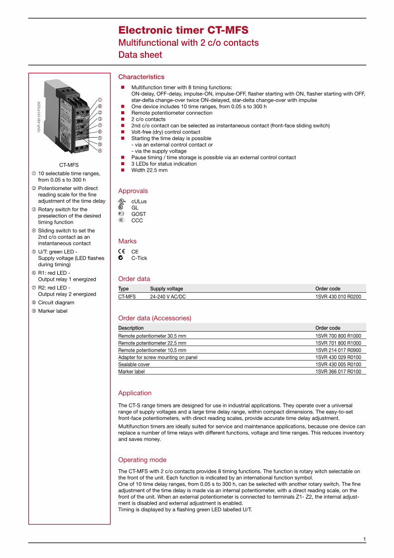
CT-MFS
1 10 selectable time ranges, from 0.05 s to 300 h
2 Potentiometer with direct reading scale for the fine adjustment of the time delay
3 Rotary switch for the preselection of the desired timing function
4 Sliding switch to set the 2nd c/o contact as an instantaneous contact
5 U/T: green LED - Supply voltage (LED flashes during timing)
6 R1: red LED - Output relay 1 energized
7 R2: red LED - Output relay 2 energized
8 Circuit diagram
9 Marker label
Characteristics
Multifunction timer with 8 timing functions: ON-delay, OFF-delay, impulse-ON, impulse-OFF, flasher starting with ON, flasher starting with OFF, star-delta change-over twice ON-delayed, star-delta change-over with impulse
One device includes 10 time ranges, from 0.05 s to 300 h Remote potentiometer connection 2 c/o contacts 2nd c/o contact can be selected as instantaneous contact (front-face sliding switch) Volt-free (dry) control contact Starting the time delay is possible
- via an external control contact or - via the supply voltage
Pause timing / time storage is possible via an external control contact 3 LEDs for status indication Width 22.5 mm
Approvals
a cULus b GL e GOST f CCC
Marks
g CE c C-Tick
Order dataType Supply voltage Order code
CT-MFS 24-240 V AC/DC 1SVR 430 010 R0200
Order data (Accessories)Description Order code
Remote potentiometer 30.5 mm 1SVR 700 800 R1000Remote potentiometer 22.5 mm 1SVR 701 800 R1000Remote potentiometer 10.5 mm 1SVR 214 017 R0900Adapter for screw mounting on panel 1SVR 430 029 R0100Sealable cover 1SVR 430 005 R0100Marker label 1SVR 366 017 R0100
Application
The CT-S range timers are designed for use in industrial applications. They operate over a universal range of supply voltages and a large time delay range, within compact dimensions. The easy-to-set front-face potentiometers, with direct reading scales, provide accurate time delay adjustment.
Multifunction timers are ideally suited for service and maintenance applications, because one device can replace a number of time relays with different functions, voltage and time ranges. This reduces inventory and saves money.
Operating mode
The CT-MFS with 2 c/o contacts provides 8 timing functions. The function is rotary witch selectable on the front of the unit. Each function is indicated by an international function symbol. One of 10 time delay ranges, from 0.05 s to 300 h, can be selected with another rotary switch. The fine adjustment of the time delay is made via an internal potentiometer, with a direct reading scale, on the front of the unit. When an external potentiometer is connected to terminals Z1- Z2, the internal adjust-ment is disabled and external adjustment is enabled. Timing is displayed by a flashing green LED labelled U/T.
Electronic timer CT-MFSMultifunctional with 2 c/o contactsData sheet

2
Function diagrams
A ON-delay (delay on make)
If control contact Y1-Z2 is open, timing begins when supply voltage is applied to A1-A2. Or, if supply voltage is already applied, opening control contact Y1-Z2 also starts timing. The green LED flashes during timing. When the selected time delay is complete, the output relays energi-ze and the flashing green LED turns steady. If supply voltage is interrupted, the output relays de-energize and the time delay is reset. If control contact Y1-Z2 closes before the time delay is complete, the time delay is reset and the output relays remain de-energized. Timing can be paused by closing control contact X1-Z2. The elapsed time is stored and continues from this time value when X1-Z2 is re-pened. This can be repeated as often as required. When an external potentiometer is connected to terminals Z1-Z2, the internal, front-face potentiometer is disabled and the time adjustment is made via the external potentiometer. If the front-face sliding switch is set to the “Inst.” position, the 2nd c/o contact energizes immediately upon application of the supply voltage.
A1-A2
15-16, 25-26
21-2421-22
15-18, 25-28
t1 ts t2t
X1-Z2
Y1-Z2
2CD
C 2
52 0
18 F
0205
green LED
t = adjusted delay time ts = storage time t = t1 + t2
BOFF-delay (Delay on break)
This function requires continuous supply voltage at terminals A1-A2 for timing. Timing is controlled by a volt-free control contact, connected to terminals Y1-Z2. If the control contact is closed, the output relays energize. If the control contact is opened, the selected time delay starts (minimum control pulse length is 20 ms). The green LED flashes during timing. When the time delay is complete, the output relays de-energize and the flashing green LED turns steady. If control contact Y1-Z2 closes before the time delay is complete, the time delay is reset and the output relays remain energized. Timing can be paused by closing control contact X1-Z2. The elapsed time is stored and continues from this time value when X1-Z2 is re-opened. This can be repeated as often as required. When an external potentiometer is connected to terminals Z1-Z2, the internal, front-face potentiometer is disabled and the time adjustment is made via the external potentiometer. If the front-face sliding switch is set to the “Inst.” position, the 2nd c/o contact energizes immediately upon application of the supply voltage.
A1-A2
15-16, 25-26
21-2421-22
15-18, 25-28
t1 ts t2t
X1-Z2
Y1-Z2
2CD
C 2
52 0
27 F
0205
green LED
t = adjusted delay time ts = storage time t = t1 + t2
Electronic timer CT-MFSMultifunctional with 2 c/o contactsData sheet

3
D Impulse-ON (Interval)
The output relays energize immediately when the supply voltage is applied to terminals A1-A2 and de-energize after the set pulse time is complete. The green LED flashes during timing. When the selected pulse time is complete, the flashing green LED turns steady. Timing can be started by opening control contact Y1-Z2, with supply voltage applied. Closing control contact Y1-Z2, before the time delay is complete, de-energizes the output relays and the time delay is reset. Timing can be paused by closing control contact X1-Z2. The elapsed time is stored and continues from this time value when X1-Z2 is re-opened. This can be repeated as often as required. When an external potentiometer is connected to terminals Z1-Z2, the internal, front-face potentiometer is disabled and the time adjustment is made via the external potentiometer. If the front-face sliding switch is set to the “Inst.” position, the 2nd c/o contact energizes immediately upon application of the supply voltage.
A1-A2
15-16, 25-26
21-2421-22
15-18, 25-28
t1 ts t2t
X1-Z2
Y1-Z2
2CD
C 2
52 0
46 F
0205
green LED
t = adjusted pulse time ts = storage time t = t1 + t2
E Impulse-OFF (Trailing edge interval)
This function requires continuous supply voltage at terminals A1-A2. Opening control contact Y1-Z2, energizes the output relays immediately and timing begins. The green LED flashes during timing. When the selected pulse time is complete, the flashing green LED turns steady and the output relays de-ener-gize. Closing control contact Y1-Z2, before the time delay is complete, de-energizes the output relays and the time delay is reset. Timing can be paused by closing control contact X1-Z2. The elapsed time is stored and continues from this time value when X1-Z2 is re-opened. This can be repeated as often as required. When an external potentiometer is connected to terminals Z1-Z2, the internal, front-face potentiometer is disabled and the time adjustment is made via the external potentiometer. If the front-face sliding switch is set to the “Inst.” position, the 2nd c/o contact energizes immediately upon application of the supply voltage.
A1-A2
15-16, 25-26
21-2421-22
15-18, 25-28
t1 ts t2t
X1-Z2
Y1-Z2
2CD
C 2
52 0
55 F
0205
green LED
t = adjusted pulse time ts = storage time t = t1 + t2
Electronic timer CT-MFSMultifunctional with 2 c/o contactsData sheet

4
F Flasher with symmetrical ON & OFF times, starting with the ON time (Recycling equal times, ON first)
Applying supply voltage to terminals A1-A2, starts timing with symmetrical ON & OFF times. The cycle starts with an ON time first. The ON & OFF times are displayed by the flashing green LED, which flashes twice as fast during the OFF time. Closing control contact Y1-Z2, with supply voltage applied, de-energizes the output relays. Opening control contact Y1-Z2, starts the timer pulsing again with the set cycle. When an external potentiometer is connected to terminals Z1-Z2, the internal, front-face potentiometer is disabled and the time adjustment is made via the external potentiometer. If the front-face sliding switch is set to the “Inst.” position, the 2nd c/o contact energizes immediately upon application of the supply voltage.
A1-A2
15-16, 25-26
21-2421-22
15-18, 25-28
t t
Y1-Z2
2CD
C 2
52 0
62 F
0205
green LED
t = adjusted flashing time
G Flasher with symmetrical ON & OFF times, starting with the OFF time (Recycling equal times, OFF first)
Applying supply voltage to terminals A1-A2, starts timing with symmetrical ON & OFF times. The cycle starts with an OFF time first. The ON & OFF times are displayed by the flashing green LED, which flashes twice as fast during the OFF time. Closing control contact Y1-Z2, with supply voltage applied, de-energizes the output relays. Opening control contact Y1-Z2 starts the timer pulsing again with the set cycle. When an external potentiometer is connected to terminals Z1-Z2, the internal, front-face potentiometer is disabled and the time adjustment is made via the external potentiometer. If the front-face sliding switch is set to the “Inst.” position, the 2nd c/o contact energizes immediately upon application of the supply voltage.
A1-A2
15-16, 25-26
21-2421-22
15-18, 25-28
t t
Y1-Z2
2CD
C 2
52 0
71 F
0205
green LED
t = adjusted flashing time
Electronic timer CT-MFSMultifunctional with 2 c/o contactsData sheet

5
I Star-delta change-over, twice ON-delayed (Star-delta starting, delay on make / delay on make)
Applying supply voltage to terminals A1-A2, energizes the star contactor connected to terminals 15-16 and begins the set starting time. The green LED flashes during timing. When the starting time is complete, the first c/o contact de-energizes the star contactor. Now, the fix transition time of 50 ms starts. When the transition time is complete, the second output relay energizes the delta contactor connected to terminals 25-28. The delta contactor remains energized as long as the supply voltage is applied to the unit. The “Inst” sliding switch (to set the 2nd c/o contact as an instantaneous contact) is disabled when this function is selected.
A1-A2
25-2625-28
t1 t2
15-1815-16
2CD
C 2
52 0
80 F
0205
green LED
Star contactor
Delta contactor
t1 = adjustable starting time t2 = transition time (approx. 50 ms)
J Star-delta change-over with impulse function (Star-delta starting, interval / delay on make)
Applying supply voltage to terminals A1-A2, energizes the star contactor connected to terminals 15-18 and begins the set starting time. The green LED flashes during timing. When the starting time is complete, the first c/o contact de-energizes the star contactor. Now, the fix transition time of 50 ms starts. When the transition time is complete, the second output relay energizes the delta contactor connected to terminals 25-28. The delta contactor remains energized as long as the supply voltage is applied to the unit. The “Inst” sliding switch (to set the 2nd c/o contact as an instantaneous contact) is disabled when this function is selected.
A1-A2
25-2625-28
t1 t2
15-1815-16
2CD
C 2
52 0
86 F
0205
green LED
Star contactor
Delta contactor
t1 = adjustable starting time t2 = transition time (approx. 50 ms)
Electronic timer CT-MFSMultifunctional with 2 c/o contactsData sheet

6
Connection diagram
CT-MFS
2CD
C 2
52 0
91 F
0005A1
A1 15 2125
A2 16 18 26 2822 24
15Z2
28 2624 22 Y1
X1
18 16 A2
Z1 25 21
Version: 1SVR 430 010 R0200 A1-A2 Supply: 24-240 V AC/DC Z1-Z2 Remote potentiometer Y1-Z2 Control contact to start timing X1-Z2 Control contact to pause timing 15-16/18 1. c/o contact 25-26/28 2. c/o contact 21-22/24 2. c/o contact as instantaneous contact
Electronic timer CT-MFSMultifunctional with 2 c/o contactsData sheet

7
Wiring notes
Connection diagram for remote potentiometer
L1
A1Z2Z1
Z1Z2
Z1
Z2
N
A2
Z2
2CD
C 2
52 2
77 F
0205
Potentiometer 50 k�
Connection diagram for control contacts
L1/L+
A1X1Z2
Z2X1
X1
Z2
N/L-
A2Y1
Y1
Y1 Z2
2CD
C 2
52 2
78 F
0205
star
t tim
ing
pau
se t
imin
g /
time
stor
age
Connection diagram for proximity switch (3 wire) with 230 V AC supplyL+
A1Z2
Z2
Z2
L-
A2Y1
Y1
Y1
24 V
/ D
C
L1
N
230
V /
AC
2CD
C 2
52 2
79 F
0205
Proximity switch
Connection diagram for proximity switch (3 wire) with 24 V DC supply
B1Z2
A2Y1
L+
L-
2CD
C 2
52 2
80 F
0205
Proximity switch
Electronic timer CT-MFSMultifunctional with 2 c/o contactsData sheet

8
Technical Data
Input circuitsSupply voltage A1-A2 24-240 V AC/DCPower consumption 24-240 V AC/DC approx. 2-2.5 VA/WSupply voltage tolerance -15...+10 %Supply voltage frequency AC/DC Version DC or 50/60 Hz AC Version 50/60 HzControl contact connections volt-free (dry) Y1-Z2 start timing external X1-Z2 time pause, time storageMinimum control pulse length 20 msNon-load voltage at the control contacts 10-40 V DC (no galvanic separation to supply circuit)Max. current in the control circuit 1 mAMax. cable length to the control inputs 50 mRemote potentiometer connection Z1/Z3-Z2 50 kzMax. cable length to remote potentiometer 2 x 25 m, shield connected to Z2 potentialDuty time 100 %
Timing circuitTime ranges 0.05 s - 300 h 1) 0.05-1 s 2) 0.15-3 s 3) 0.5-10 s 4) 1.5-30 s 5) 5-100 s 6) 15-300 s 7) 1.5-30 min 8) 15-300 min 9) 1.5-30 h 10) 15-300 hRecovery time < 50 msRepeat accuracy (constant parameters) < 0.2 %Timing error within the supply voltage tolerance range < 0.008 % / % d UTiming error within operating temperature range < 0.07 % / °C
Indication of operational statesSupply voltage / timer green LED steady / flashing while timing1st / 2nd output relay energized red LED / red LED
Output circuits 15-16/18, 25(21)-26(22)/28(24)Number of contacts Relays, 2 c/o contacts, 2nd c/o contact selectable as instantaneous contactContact material AgCdORelated voltage acc. to VDE 0110, IEC 60947-1 250 VMaximum switching voltage 250 V AC, 250 V DCRated switching current acc. to IEC 60947-5-1 AC-12 (resistive) 230 V 4 A AC-15 (inductive) 230 V 3 A DC-12 (resistive) 24 V 4 A DC-13 (inductive) 24 V 2 AMaximum lifetime mechanical 30 x 106 switching cycles electrical (AC-12, 230 V, 4 A) 0,1 x 10⁶ switching cyclesShort circuit proof, max. fuse rating n/c 10 A fast, operating class gL n/o 10 A fast, operating class gL
General dataEnclosure width 22.5 mm length 78.0 mm depth 100.0 mmWire size fine-strand with wire end ferrule 2 x 0.75 - 2.5 mm2 (18-14 AWG) fine-strand without wire end ferrule rigid 2 x 0.5 - 4 mm2 (20-12 AWG)Weight approx. 150 g (5.3 oz)Mounting position anyDegree of protection enclosure / terminals IP50 / IP20
Electronic timer CT-MFSMultifunctional with 2 c/o contactsData sheet

9
Temperature operating -20...+60 °C storage -40...+85 °CMounting DIN rail (EN 50022)
StandardsProduct standard IEC 61812-1, EN 61812-1EMC Directive 89/336/EECElectromagnetic compatibility IEC 61000-6-2, EN 61000-6-4ESD acc. to IEC 61000-4-2, EN 61000-4-2 level 3 6 kV / 8 kVHF radiation resistance acc. to IEC 61000-4-3, EN 61000-4-3 level 3 10 V/mBurst acc. to IEC 61000-4-4, EN 61000-4-4 level 3 2 kV / 5 kHzSurge acc. to IEC 1000-4-5, EN 61000-4-5 level 4 2 kV L-LHF line emission acc. to IEC 1000-4-6, EN 61000-4-6 level 3 10 VLow Voltage Directive 73/23/EECOperational reliability acc. to IEC 68-2-6 4 gMechanical resistance acc. to IEC 68-2-6 6 g
Approvals / marksApprovals cULus, GL, GOST and CCCMarks CE and C-Tick
Isolation dataRated insulation voltage between supply circuit, acc. to VDE 0110, IEC 60947-1 supply up to 240 V: 300 V control circuit and output circuit supply up to 440 V: 500 VRated impulse withstand voltage between all isolated circuits acc. to VDE 0110, IEC 664 4 kV / 1.2-50 µs Test voltage between all isolated circuits 2.5 kV, 50 Hz, 1 min.Pollution category acc. to VDE 0110, IEC 664, IEC 255-5 III/COvervoltage category acc. to VDE 0110, IEC 664, IEC 255-5 III/CEnvironmental testing acc. to IEC 68-2-30 24 h cycle time, 55 °C, 93 % rel., 96 h
Load limit curves
AC load (resistive)
300
200
1008060504030
20
101 2 4 6 10
I A
V
2CD
C 2
52 1
94 F
0205
V
0.1 0.2 0.5
DC load (resistive)
300
200
1008060504030
20
101 2 4 6 10
I A
V
2CD
C 2
52 1
93 F
0205
V
0.1 0.2 0.5
Derating factor F for inductive AC load
cos ϕ
F
2CD
C 2
52 1
92 F
0205
0.5
0.1 0.2 0.3 0.4 0.5 0.6 0.7 0.8 0.9 1.0
0.6
0.7
0.8
0.9
1.0
Electronic timer CT-MFSMultifunctional with 2 c/o contactsData sheet

10
Contact lifetime /switching cycles N
4321104
2
3 4
N
I A
5
8 9
105
5 6 7 8
2CD
C 2
52 1
91 F
0205
220 V 50 Hz 1 AC 360 cycles/h
Dimensional drawings
Dimensions in mm
2CD
C 2
52 1
88 F
0005
100
102
109,5 4.31“ 22,5
.886“78
3.07
“4.02“
3.94“
Dimensional drawings (Accessories)
2CD
C 2
52 1
84 F
0005
ø36
1...7ø30
33 40
DIA
. 1.4
2”
DIA
. 1.1
8”
.39”...2.75”
1.30” 1.57”
Remote potentiometer 30.5 mm
2CD
C 2
52 1
83 F
0005
ø29
DIA
. 1.1
4”
DIA
. .86
6”
.39”...2.75”
1.30” 1.65”
ø22 1...7
33 42
Remote potentiometer 22.5 mm
50
ø22
max. 5
26
20
3,5
1.97” max .2”
DIA. .866”
.787”
1.02”
.138
”
2CD
C 2
52 1
82 F
0005
Remote potentiometer 10.5 mm
Electronic timer CT-MFSMultifunctional with 2 c/o contactsData sheet

11
2CD
C 2
52 1
87 F
0005
4,5 62,5
60
1011
,5
22,5
.177
”
2.46”
2.36”
.394
”
.886
”
.453
”
Adapter for screw mounting on panel
2CD
C 2
52 1
85 F
000522,5
68,5
73,5
.886”
2.70
”
.138”.275”
front-to-backsize 107
Sealable cover
203A11 8
.315
”
.787”
2CD
C 2
52 1
86 F
0005
Marker label
Electronic timer CT-MFSMultifunctional with 2 c/o contactsData sheet

ABB STOTZ-KONTAKT GmbHEppelheimer Straße 82 69123 Heidelberg, DeutschlandPostfach 10 16 80 69006 Heidelberg, DeutschlandInternet http://www.abb.com/lowvoltage -> Control Products -> Electronic RelaysE-Mail [email protected]
Dru
cksc
hrift
-Num
mer
. 2C
DC
111
008
D02
01P
rinte
d in
the
Fed
eral
Rep
ublik
of G
erm
any
(08/
05)