electronic toll collection system for billing using ...ijaers.com/paper-oct...
TRANSCRIPT

International Journal of Advanced Engineering Research and Science (IJAERS) [Vol-1, Issue-5, Oct.- 2014] ISSN: 2349-6495
Page | 33
Electronic Toll Collection System For Billing Using Wireless Communication
K. Kanthi kumar1, Dontabhaktuni Jayakumar2, K. Jail Singh3
1Associate Professor, Department of Electronics and Communication Engineering, Holy Mary Institute of Technology and Science, Bogaram (V), Keesara (M), Rangareddy (D), Telangana, India.
2Assistant Professor, Department of Electronics and Communication Engineering, Holy Mary Institute of Technology and Science, Bogaram (V), Keesara (M), Rangareddy (D), Telangana, India.
3Assistant Professor, Department of Electronics and Communication Engineering, Holy Mary Institute of Technology and Science, Bogaram (V), Keesara (M), Rangareddy (D), Telangana, India.
Abstract— The main theme of this paper is to avoid human existence at the toll gates and it plays an automatic role in permitting the vehicle to go/stop by taking the payment. This paper plays a vital role now a day because we use RFID technology with GSM to develop the Application. The role of RFID is to identify the vehicle. When the Vehicle is entered then RFID will be active and the reader reads the tag and microcontroller checks with the database for the balance for the balance enquiry. If sufficient amount exits in the card then the gate will be opened and whenever the vehicle crosses then with in 2min automatically gate will be closed. If the balance is not available in the card then gate will not be opened. We also have GPS in this Paper to locate the vehicle. We use GSM to know that where the vehicle is located exactly by sending a message. The controller receives it and responds back with values of latitude and longitude given by GPS. In the above, we use ARM7 processor for the vehicle section of the system, which is a high end 32 bit microprocessor, executes the instructions very fast and we use PIC microcontroller for the transmitting section of the system.
I. INTRODUCTION
Generally to make the payments of electricity, gas, water etc., we need to go respective areas. It was risky and time consuming process. As one of the major research topics in intelligent transportation system(ITS) electronic toll collection (ETC) system is considered as an effective method in order to alleviate traffic congestion and jams, enhance the convenience and safety of travelers, and minimize air pollution and fuel consumption for environmental protection need. The Electronic Toll Collection (ETC) is a technology that permits vehicles to pay highway tolls electronically. E-Z Pass is the nation’s first toll collection system. This automation has replaced live attendants at toll stations that collect fees manually. Electronic Toll Collection is a
concept that is being readily accepted globally. Some tags are designed to communicate with other kinds of roadside readers as well, making interstate and intrastate toll payments accessible. Toll agencies are interested in developing these tags and readers because they can simplify the tolling system The evolution of communication technology has brought ETC systems from SLFF (Single Lane Free Flow) to MLFF (Multi-Lane Free Flow), and area wide integrated MLFF road charging system is now currently on its development. DSRC-based ETC systems will gradually evolve to the area wide integrated road charging solution based on mobile communication technology. Most of the current ETC implementations are based on RFID, the vehicle positioning system using global positioning system (GPS) and mobile communication technique. Objective of the concept The main objective of this paper ELECTRONIC TOLL COLLECTION SYSTEM is to ease the collecting toll and reduce traffic and improve service. The RFID card will be given to the user which contains the digital code, which has the corresponding details stored in the centralized database system which can be accessed in the relevant office as and when required. We can use ETC in any kind of environment. At the tollgates, instead of a person collecting the amounts of vehicles. We use an automated system which helps us to reduce the man power. A system with RFID (radio frequency identification) is used to identify the vehicle. When the vehicle is identified, then the next step the controller will check for the balance in the card. If there is a sufficient amount in the card, then we are allowed to move forward means the gate will be opened automatically and if the card does not have balance then we are not allowed means gate will not be opened. We can also track the vehicle using GPS and GSM in this Paper. We can provide the coordination with above in the real criteria. The GSM (Global Standard for mobile communication) which is used

International Journal of Advanced Engineering Research and Science (IJAERS) [Vol-1, Issue-5, Oct.- 2014] ISSN: 2349-6495
Page | 34
to send the message for retrieving the longitude and latitude values from GPS. Therefore, we can track the vehicle location with the GPS values. 1.1 Details of Electronic Toll Collection System 1.1.1 RFID As an evolutionary automatic identification technology, RFID was considered a niche technology a few years ago. As the costs associated with RFID hardware have decreased, and standards defined for managing data, RFID has gone main stream. It has the potential of powering business systems such that they become the competitive backbone of organizations. Radio-frequency identification (RFID) is an automatic identification method, relying on storing and remotely retrieving data using devices called RFID tags or transponders. An RFID tag is an object that can be applied to or incorporated into a product, animal, or person for the purpose of identification using radio waves. Some tags can be read from several meters away and beyond the line of sight of the reader. Most RFID tags contain at least two parts. One is an integrated circuit for storing and processing information, modulating and demodulating a (RF) signal and can also be used for other specialized functions. The second is an antenna for receiving and transmitting the signal. A technology called chip less RFID allows for discrete identification of tags without an integrated circuit, thereby allowing tags to be printed directly onto assets at lower cost than traditional tags. Today, a significant thrust in RFID use is in enterprise supply chain management, improving the efficiency of inventory tracking and management. However, a threat is looming that the current growth and adoption in enterprise supply chain market will not be sustainable. A fair cost-sharing mechanism, rational motives and justified returns from RFID technology investments are the key ingredients to achieve long-term and sustainable RFID technology adoption. 1.1.2 ETC Transmitting Module: In a typical RFID based ETC system, individual objects are equipped with a small, inexpensive tag. The tag contains a transponder with a digital memory chip that is given a unique electronic product code. The interrogator, an antenna packaged with a transceiver and decoder, emits a signal activating the RFID tag so it can read and write data to it. When an RFID tag passes through the electromagnetic zone, it detects the reader's activation signal. The reader decodes the data encoded in the tag's integrated circuit (silicon chip) and the data is passed to the host computer.
Fig. 1: Complete RFID System Vehicle Module: A GSM modem is used to send the position (Latitude and Longitude) of the vehicle from a remote place. The GPS modem will continuously give the data i.e. the latitude and longitude indicating the position of the vehicle. The GPS modem gives many parameters as the output, but only the NMEA data coming out is read and displayed on to the LCD. The same data is sent to the mobile at the other end from where the position of the vehicle is demanded.
Fig. 2: Transmitter and Receiver
II. LITERATURE SURVEY 2.1 History of the ETC Electronic toll collection (E-Tolls), an adaptation of
military "identification friend or foe" technology, aims
to eliminate the delay on toll roads by collecting tolls
electronically. ETC determines whether the cars passing are enrolled in the program, alerts enforcers for those that are

International Journal of Advanced Engineering Research and Science (IJAERS) [Vol-1, Issue-5, Oct.- 2014] ISSN: 2349-6495
Page | 35
not, and electronically debits the accounts of registered car owners without requiring them to stop. In 1959, Nobel Economics Prize winner William Vickrey was the first to propose a system of electronic tolling for the Washington Metropolitan Area. He proposed that each car would be equipped with a transponder. “The transponder’s personalized signal would be picked up when the car passed through an intersection, and then relayed to a central computer which would calculate the charge according to the intersection and the time of day and add it to the car’s bill”[1] Electronic toll collection has facilitated the concession to the private sector of the construction and operation of urban freeways, as well as made feasible the improvement and the practical implementation of road congestion pricing schemes in a limited number of urban areas to restrict auto travel in the most congested areas. In the 1960s and 1970s, free flow tolling was tested with fixed transponders at the undersides of the vehicles and readers, which were located under the surface of the highway.[2] Norway has been the world's pioneer in the widespread implementation of this technology. ETC was first introduced in Bergen, in 1986, operating together with traditional tollbooths. In 1991, Trondheim introduced the world's first use of completely unaided full-speed electronic tolling. Norway now has 25 toll roads operating with electronic fee collection (EFC), as the Norwegian technology is called (see AutoPASS). In 1995, Portugal became the first country to apply a single, universal system to all tolls in the country, the Via Verde, which can also be used in parking lots and gas stations. The United States is another country with widespread use of ETC in several states, though many U.S. toll roads maintain the option of manual collection. Open road tolling (ORT) is a type of electronic toll collection without the use of toll booths. The major advantage to ORT is that users are able to drive through the toll plaza at highway speeds without having to slow down to pay the toll. 2.2 Existing Systems
Fig. 3:
Fig. 4:
Initially the gates at the tollgate will be closed and it will be opened when the payment will be made. So when the vehicle is identified then the RFID will fetch the unique id from the vehicle and gives it to the microcontroller. The microcontroller always monitors the RFID reader. When any data is received by controllers then it will checks for it details from its database. If the vehicle is having sufficient amount. Then the controller will deduct the amount according to the norms and make the gate to open and after 2 minutes then microcontroller closes the gate. This will be done automatically. We have GPS and GSM technology’s which plays a major role in locating the position and transmission and reception of the data. This is useful when we want to know the position of the vehicle. The GPS Contained by the vehicle will tell us about the vehicle location by giving the LATITUDE and LONGITUDE values and this is done when we send message to the GSM modem which is also contained by the vehicle. So whenever the controller receives the data from the GSM modem. It will reply back to the number with GPS values. 2.3 Technical details about GSM: GSM is a cellular network, which means that mobile phones connect to it by searching for cells in the immediate vicinity.

International Journal of Advanced Engineering Research and Science (IJAERS) [Vol-1, Issue-5, Oct.- 2014] ISSN: 2349-6495
Page | 36
There are five different cell sizes in a GSM network—macro, micro, pico, femto and umbrella cells. The coverage area of each cell varies according to the implementation environment. Macro cells can be regarded as cells where the base station antenna is installed on a mast or a building above average roof top level. Micro cells are cells whose antenna height is under average roof top level; they are typically used in urban areas. Picocells are small cells whose coverage diameter is a few dozen metres; they are mainly used indoors. Femtocells are cells designed for use in residential or small business environments and connect to the service provider’s network via a broadband internet connection. Umbrella cells are used to cover shadowed regions of smaller cells and fill in gaps in coverage between those cells. Cell horizontal radius varies depending on antenna height, antenna gain and propagation conditions from a couple of hundred meters to several tens of kilometres. The longest distance the GSM specification supports in practical use is 35 kilometres (22 mi). There are also several implementations of the concept of an extended cell[12], where the cell radius could be double or even more, depending on the antenna system, the type of terrain and the timing advance. Indoor coverage is also supported by GSM and may be achieved by using an indoor picocell base station, or an indoor repeater with distributed indoor antennas fed through power splitters, to deliver the radio signals from an antenna outdoors to the separate indoor distributed antenna system. These are typically deployed when a lot of call capacity is needed indoors; for example, in shopping centers or airports. However, this is not a prerequisite, since indoor coverage is also provided by in-building penetration of the radio signals from any nearby cell. The modulation used in GSM is Gaussian minimum-shift keying (GMSK), a kind of continuous-phase frequency shift keying. In GMSK, the signal to be modulated onto the carrier is first smoothed with a Gaussian low-pass filter prior to being fed to a frequency modulator, which greatly reduces the interference to neighboring channels (adjacent channel interference). 2.4 GSM network structure: The network behind the GSM seen by the customer is large and complicated in order to provide all of the services which are required. It is divided into a number of sections and these are each covered in separate articles. the Base Station Subsystem (the base stations and their controllers).
the Network and Switching Subsystem (the part of the network most similar to a fixed network). This is sometimes also just called the core network. the GPRS Core Network (the optional part which allows packet based Internet connections).all of the elements in the system combine to produce many GSM services such as voice calls and SMS.
Fig. 4:
2.5 Global Positioning System The Global Positioning System (GPS) is a Global Navigation Satellite System (GNSS) developed by the United States Department of Defense. It is the only fully functional GNSS in the world. It uses a constellation of between 24 and 32 Medium Earth Orbit satellites that transmit precise microwave signals, which enable GPS receivers to determine their current location, the time, and their velocity. Its official name is NAVSTAR GPS . GPS is often used by civilians as a navigation system. A GPS receiver calculates its position by precisely timing the signals sent by the GPS satellites high above the Earth. Each satellite continually transmits messages containing the time the message was sent, precise orbital information, and the general system health and rough orbits of all GPS satellites. The receiver measures the transit time of each message and computes the distance to each satellite. Geometric trilateration is used to combine these distances with the location of the satellites to determine the receiver's location. The position is displayed, perhaps with a moving map display or latitude and longitude; elevation information may be included. Many GPS units also show derived information such as direction and speed, calculated from position changes.PS consists of three segments - the satellite constellation, ground control network, and user equipment. Space segment - The satellite constellations that provide the ranging signals and navigation data messages to the user equipment. Control segment - Ground control network which tracks and maintains the satellite constellation by monitoring satellite health and signal integrity and maintaining satellite orbital configuration.

International Journal of Advanced Engineering Research and Science (IJAERS) [Vol-1, Issue-5, Oct.- 2014] ISSN: 2349-6495
Page | 37
User segment - User equipment. A visual example of the GPS constellation in motion with the Earth rotating. Notice how the number of satellites in view from a given point on the Earth's surface, in this example at 45°N, changes with time. 2.5.1 Introduction to tracking system: A GPS tracking unit is a device that uses the Global Positioning System to determine the precise location of a power lines, person, or other asset to which it is attached and to record the position of the asset at regular intervals. The recorded location data can be stored within the tracking unit, or it may be transmitted to a central location data base, or internet-connected computer, using a cellular (GPRS), radio, or satellite modem embedded in the unit. This allows the asset's location to be displayed against a map backdrop either in real-time or when analyzing the track later, using customized software. Usually, a GPS tracker will fall into one of these three categories: Data Loggers:- A GPS logger simply logs the position of the device at regular intervals in its internal memory. Modern GPS loggers have either a memory card slot, or internal flash memory and a USB port. Some act as a USB flash drive. This allows downloading of the data for further analysis in a computer. i.e. Sports persons, gliding etc… Data pushers:- This is the kind of devices used by the security industry, which pushes (i.e. "sends") the position of the device, at regular intervals, to a determined server, that can instantly analyze the data. i.e. Fleet control, Stolen Power lines control, Race control etc. Data pullers:- Contrary to a data pusher, that sends the position of the device at regular intervals (push technology), these devices are always-on and can be queried as often as required (pull technology). This technology is not in widespread use, but an example of this kind of device is a computer connected to the Internet and running gpsd. Data Pullers are coming into more common usage in the form of devices containing a GPS receiver and a cell phone which, when sent a special SMS message reply to the message with their location.
Fig. 5: The traced path of a tracking device
2.6 RFID Module Radio-frequency identification (RFID ) is an automatic identification method, relying on storing and remotely retrieving data using devices called RFID tags or transponders. The technology requires some extent of cooperation of an RFID reader and an RFID tag. An RFID tag is an object that can be applied to or incorporated into a product, animal, or person for the purpose of identification and tracking using radio waves. Some tags can be read from several meters away and beyond the line of sight of the reader. Most RFID tags contain at least two parts. One is an integrated circuit for storing and processing information, modulating and demodulating a radio-frequency (RF) signal, and other specialized functions. The second is an antenna for receiving and transmitting the signal.There are generally two types of RFID tags: Active RFID tags, which contain a battery, and Passive RFID tags, which have no battery. Future Chip less RFID allows for discrete identification of tags without an integrated circuit, thereby allowing tags to be printed directly onto assets at a lower cost than traditional tags. 2.6.1 Varieties of RFID Tags RFID tags come in three general varieties passive, active, or semi-passive (also known as battery-assisted or semi-active) and beacon types. Passive tags require no internal power source, thus being pure passive devices (they are only active when a reader is nearby to power them by wireless illumination), whereas semi-passive and active tags require a power source, usually a small battery. Beacon tags transmit autonomously with a certain blink pattern and do not respond to interrogation. Passive

International Journal of Advanced Engineering Research and Science (IJAERS) [Vol-1, Issue-5, Oct.- 2014] ISSN: 2349-6495
Page | 38
Passive RFID tags have no internal power supply. The minute electrical current induced in the antenna by the incoming radio frequency signal provides just enough power for the CMOS integrated circuit in the tag to power up and transmit a response. Most passive tags signal by backscattering the carrier wave from the reader. This means that the antenna has to be designed both to collect power from the incoming signal and also to transmit the outbound backscatter signal. The response of a passive RFID tag is not necessarily just an ID number; the tag chip can contain non-volatile data, possibly writable EEPROM for storing data. Active Unlike passive RFID tags, active RFID tags have their own internal power source, which is used to power the integrated circuits and to broadcast the response signal to the reader. Communications from active tags to readers is typically much more reliable (i.e. fewer errors) than those from passive tags due to the ability for active tags to conduct a "session" with a reader. Active tags, due to their onboard power supply, also may transmit at higher power levels than passive tags, allowing them to be more robust in "RF challenged" environments with humidity and spray or with RF-dampening targets (including humans and cattle, which contain mostly water), reflective targets from metal (shipping containers, vehicles), or at longer distances. In turn, active tags can be larger (due to battery size) and more expensive to manufacture (due to price of the battery). However, the potential shelf life of an active tag can be many years. Many active tags today have operational ranges of hundreds of meters, and a battery life from several months to 10 years. Active tags may include larger memories than passive tags, and may include the ability to store additional information received from the reader. Special active RFID tags may include specialized sensors. For example, a temperature sensor can be used to record the temperature profile during the transportation and storage of perishable goods. Other sensor types used include humidity, shock/vibration, light, nuclear radiation, pressure and concentrations of gases such as ethylene. Increasingly, active tags on the market today are internationally standardized according to the ISO 18000-7 air interface standard, which operates at the 433 MHz frequency. In addition, active tags that are sold in the form of an electronic seal are standardized according to the ISO 18185 standard. Beacon tags
Beacon tags blink the coded identity signal at a regular pattern. This may be a constant blink rate or a blink rate with stochastic shift or some triggered blinking. Not to activate the responder function in a tag first prevents from limiting the speed capabilities and improves the availability of the identification information under noisy conditions. Therefore the beacon concept appliers to very robust processes: The regular availability of the coded signal reduces latency and allows for low power levels, as with active tags. However, the permanent talk of many tags may pollute the frequency channel and therefore prevent from operating in denser populations. The design of the blinking scheme must take the battery life cycle into account. Currently (2008) none of the offered products follows any known line of international standardization. However, all blinking must obey the national wireless communications regulations concerning power level and channel occupation. Antenna Types The antenna used for an RFID tag is affected by the intended application and the frequency of operation. Low-frequency is 30–300 kHz. LFID or Low FID passive tags are normally inductively coupled, and because the voltage induced is proportional to frequency, many coil turns are needed to produce enough voltage to operate an integrated circuit. Compact Low FID tags, like glass-encapsulated tags used in animal and human identification, use a multilayer coil (3 layers of 100–150 turns each) wrapped around a ferrite core. High frequency is 3-30 MHz At 13.56 MHz, a HFID or High FID tag, using a planar spiral with 5–7 turns over a credit-card-sized form factor can be used to provide ranges of tens of centimeters. These coils are less costly to produce than LF coils, since they can be made using lithographic techniques rather than by wire winding, but two metal layers and an insulator layer are needed to allow for the crossover connection from the outermost layer to the inside of the spiral where the integrated circuit and resonance capacitor are located. Ultrahigh-frequency or UHF is 300 MHz-3 GHz. UHFID and microwave passive tags are usually radioactively-coupled to the reader antenna and can employ conventional dipole-like antennas. Only one metal layer is required, reducing cost of manufacturing. Dipole antennas, however, are a poor match to the high and slightly capacitive input impedance of a typical integrated circuit. Folded dipoles, or short loops acting as inductive matching structures, are often employed to improve power delivery to the IC. Half-wave dipoles (16 cm at 900 MHz) are too big for many applications; for example,

International Journal of Advanced Engineering Research and Science (IJAERS) [Vol-1, Issue-5, Oct.- 2014] ISSN: 2349-6495
Page | 39
tags embedded in labels must be less than 10 cm (4 inches) in extent. To reduce the length of the antenna, antennas can be bent or meandered, and capacitive tip-loading or bowtie-like broadband structures are also used. Compact antennas usually have gain less than that of a dipole that is less than 2 dB and can be regarded as isotropic in the plane perpendicular to their axis. Dipoles couple to radiation polarized along their axes, so the visibility of a tag with a simple dipole-like antenna is orientation-dependent. Tags with two orthogonal or nearly-orthogonal antennas, often known as dual-dipole tags, are much less dependent on orientation and polarization of the reader antenna, but are larger and more expensive than single-dipole tags. Patch antennas are used to provide service in close proximity to metal surfaces, but a structure with good bandwidth is 3–6 mm thick, and the need to provide a ground layer and ground connection increases cost relative to simpler single-layer structures. HFID and UHFID tag antennas are usually fabricated from copper or aluminum. Conductive inks have seen some use in tag antennas but have encountered problems with IC adhesion and environmental stability. Tag attachment There are three different kinds of RFID tags based on their attachment with identified objects, i.e. attachable, implantable and insertion tags [10]. In addition to these conventional RFID tags, Eastman Kodak Company has filed two patent applications for monitoring ingestion of medicine based on a digestible RFID tag. RFID Backscatter To communicate, tags respond to queries generating signals that must not create interference with the readers, as arriving signals can be very weak and must be differentiated. Besides backscattering, load modulation techniques can be used to manipulate the reader's field. Typically, backscatter is used in the far field, whereas load modulation applies in the near field, within a few wavelengths from the reader. 2.7 Microcontroller LPC2148 The CPU at the heart of the LPC2000 family is the ARM7. The LPC2141/42/44/46/48 microcontrollers are based on a 16-bit/32-bit ARM7TDMI-S CPU with real-time emulation and embedded trace support, that combine microcontroller with embedded high speed flash memory ranging from 32 KB to 512 KB. A 128-bit wide memory interface and a unique accelerator architecture enable 32-bit code execution at the maximum clock rate. Serial communications interfaces ranging from a USB 2.0 Full-speed device, multiple UARTs, SPI, SSP to I2C-bus
and on-chip SRAM of 8 kB up to 40 kB, make these devices very well suited for communication gateways and protocol converters, soft modems, voice recognition and low end imaging, providing both large buffer size and high processing power. Various 32-bit timers, single or dual 10-bit ADC(s), 10-bit DAC, PWM channels and 45 fast GPIO lines with up to nine edge or level sensitive external interrupt pins make these microcontrollers suitable for industrial control and medical systems. 2.8 Microcontroller PIC16F877A The major heart of this Paper is PIC16F877A microcontroller, the reasons why we selected this in our Paper? The PIC16F877A provides the following standard features only 35 single-word instructions to learn, all single-cycle instructions except for program branches, which are two-cycle, Operating speed: DC – 20 MHz clock input, DC – 200 ns instruction cycle, Up to 8K x 14 words of Flash Program Memory, Up to 368 x 8 bytes of Data Memory (RAM), Up to 256 x 8 bytes of EEPROM Data Memory, Pinout compatible to other 28-pin or 40/44-pin, PIC16CXXX and PIC16FXXX microcontrollers, Timer0: 8-bit timer/counter with 8-bit prescaler, Timer1 16-bit timer/counter with prescaler, can be incremented during Sleep via external crystal/clock Timer2 8-bit timer/counter with 8-bit period register, prescaler and postscaler, Two Capture, Compare, PWM modules, Capture is 16-bit, max. resolution is 12.5 ns; Compare is 16-bit, max. resolution is 200 ns PWM max. resolution is 10-bit, Synchronous Serial Port (SSP) with SPI (Master mode) and I2C (Master/Slave), Universal Synchronous Asynchronous Receiver Transmitter (USART/SCI) with 9-bit address detection, Parallel Slave Port (PSP) 8 bits wide . Architecture 16F877A 2.9 UART Serial Communication A serial port sends and receives data one bit at a time over one wire. While it takes eight times as long as to transfer each byte of data this way, only a few wires are required. In fact, two-way (full duplex) communications is possible with only three separate wires- one to send, one to receive, and a common signal ground wire.
� Bi-directional communications � Communicating by wires � The Parity Bit � Cable lengths � MAX-232C � DCE And DTE devices � Synchronous and Asynchronous
Communications Bi-directional Communications

International Journal of Advanced Engineering Research and Science (IJAERS) [Vol-1, Issue-5, Oct.- 2014] ISSN: 2349-6495
Page | 40
The serial port on your PC is a full-duplex device meaning that it can send and receive data at the same time. In order to be able to do this, it uses separate lines for transmitting and receiving data. Some types of serial devices support only one-way communications and therefore use only two-wires in the cable – the transmit line and the signal ground. Communicating by bits Once the start bit has been sent, the transmitter sends the actual data bits. There may either be 5,6,7, or 8 data bits, depending on the number you have selected. Both receiver and the transmitter must agree on the number of data bits, as well as the baud rate. Almost all devices transmit data using either 7 or 8 data bits. Notice that when only 7 data bits are employed, you cannot send ASCII values greater than 127. Likewise, using 5 bits limits the highest possible value to 31. After the data has been transmitted, a stop bit is sent. A stop bit has a value of 1- or a mark state- and it can be detected correctly even if the previous data bit also had a value of 1. This is accomplished by the stop bit’s duration. The Parity Bit Besides the synchronization provided by the use of start and stop bits, an additional bit called a parity bit may optionally be transmitted along with the data. A parity bit affords a small amount of error checking, to help detect data corruption that might occur during transmission. Cable Lengths The MAX-232 standard imposes a cable length limit of 50 feet. You can usually ignore this “standard”, since a cable can be as long as 10000 feet at baud rates up to 19200 if you use a high quality, well shielded cable. The external environment has a large effect on lengths for unshielded cables. MAX232 (Voltage Converter) Since the RS232 is not compatible with today microprocessors and micro controller, we need line driver to convert the RS232 signals to TTL voltage levels that will be acceptable to the 8051’s TXD and RXD pins. One example of such a converter is MAX 232 from maxim corp. The MAX 232 converts from RS232 voltage levels to TTL voltage levels, and vice versa. One advantage of MAX232 chip is that it uses a +5V power source, which is the same as the source voltage for the at89s52 micro controller. In other words, with a single +5v power supply we can power both the PIC and MAX 232, with no need of for the dual power supplies that are common in many older systems. The MAX 232 requires four capacitors ranging from 1 to 22 microfarad. The most widely used value for this capacitor is 22microfarad.
The MAX232 is a dual driver/receiver that includes a capacitive voltage generator to supply TIA/EIA-232-Fvoltage levels from a single 5-V supply. Each receiver converts TIA/EIA-232-F inputs to 5-V TTL/CMOS levels. These receivers have a typical threshold of 1.3 V, a typical hysterias is of 0.5 V, and can accept ±30-V inputs. Each driver converts TTL/CMOS input levels into TIA/EIA-232-F levels. DCE and DTE devices Two terms you should be familiar with are DTE and DCE. DTE stands for Data Terminal Equipment, and DCE stands for Data Communication Equipment. These terms are used to indicate the pin-out for the connectors on a device and the direction of the signals on the pins. Your computer is a DTE device, while most other devices are usually DCE devices. If you have trouble keeping the two straight then replace the term “DTE device” with your PC and the term DCE device with “remote Device” in the following discussion. The RS-232 standard states that DTE devices use a 25-pin male connector, and DCE devices use a 25-pin female connector. You can therefore connect a DTE device to a DCE using a straight pin-for-pin connection. However, to connect two like devices, you must instead use a null modem cable. Null modem cables cross the transmit and receive lines in the cable. The DTE device puts this line in a mark condition to tell the remote device that it is ready and able to receive data. If the DTE device is not able to receive data (typically because its receive buffer is almost full), it will put this line in the space condition as a signal to the DCE to stop sending data. When the DTE device is ready to receive more data it will place this line back in the mark condition. The complement of the RTS wire is CTS, which stands for Clear to Send. The DCE device puts this line in a mark condition to tell the DTE device that it is ready to receive the data. Likewise, if the DCE device is unable to receive data, it will place this line in the space condition. Together, these two lines make up what is called RTS/CTS or “hardware” flow control. The software wedge supports this type of flow control as well as Xon/Xoff or “software” flow control. Software flow control uses special control characters transmitted from one device to another to tell the other device to stop or start sending data. With software flow control the RTS and CTS lines are not used. DTR stands for Data Terminal Ready. Its intended function is very similar to the RTS line. DSR (Data Set Ready) is the companion to DTR in the same way that CTS is to RTS. Some serial devices use DTR and DSR as signals to simplify confirm that a device is connected and

International Journal of Advanced Engineering Research and Science (IJAERS) [Vol-1, Issue-5, Oct.- 2014] ISSN: 2349-6495
Page | 41
turned on. The software wedge sets DTR to the mark state when the serial port is opened and leaves it in that state until the port is closed. The DTR and DSR lines were originally designed to provide an alternate method of hardware handshaking. It would be pointless to use both RTS/CTS and DTR/DSR for flow control signals at the same time. Because of this DTR and DSR are rarely used for flow control. Synchronous and Asynchronous Communications There are two basic types of serial communications, synchronous and asynchronous. With synchronous communications, the two devices initially synchronize themselves to each other, and then continually send characters to stay in sync. Even when the data is not really being sent, a constant flow of bits allows each device to know where the other is at any given time. That is, each character that is sent is either actual data or an idle character. Synchronous communications allows faster data transfer rates than asynchronous methods, because additional bits to mark the beginning and end of each data byte are not required. The serial ports on IBM style PCs are asynchronous devices and therefore only support asynchronous serial communications. Asynchronous means no “synchronization”, and thus does not require sending and receiving idle characters. However, the beginning and end of each byte of data must be identified by start and stop bits. The start bit indicates when the data byte is about to begin and the stop bit signals when it ends. 2.10 Stepper Motor A stepper motor is an electromechanical evince which converts electrical pulses into discrete mechanical movements. The shaft or spindle of a stepper motor rotates indiscrete step increments when electrical command pulses are applied to it in the proper sequence. The motors rotation has several direct relationships to these applied input pulses. The sequence of the applied pulses is directly related to the direction of motor shafts rotation. The speed of the motor shafts rotation is directly related to the frequency of the input pulses and the length of rotation is directly related to the number of input pulses applied. Stepper motors operate differently from DC brush motors, which rotate when voltage applied to their terminals. Stepper motors, on the other hand, effectively have multiple "toothed" electromagnets arranged around a central gear-shaped piece of iron. The electromagnets are energized by an external control circuit, such as a microcontroller. To make the motor shaft turn, first one electromagnet is given power, which makes the gear's
teeth magnetically attracted to the electromagnet's teeth. When the gear's teeth are thus aligned to the first electromagnet, they are slightly offset from the next electromagnet. So when the next electromagnet is turned on and the first is turned off, the gear rotates slightly to align with the next one, and from there the process is repeated. Each of those slight rotations is called a "step," with an integer number of steps making a full rotation. In that way, the motor can be turned by a precise angle. Stepper motors nameplates typically give only the winding current and occasionally the voltage and winding resistance. The rated voltage will produce the rated winding current at DC: but this is mostly a meaningless rating, as all modern drivers are current limiting and the drive voltages greatly exceed the motor rated voltage. A stepper's low speed torque will vary directly with current. How quickly the torque falls off at faster speeds depends on the winding inductance and the drive circuitry it is attached to, especially the driving voltage. Steppers should be sized according to published torque curve, which is specified by the manufacturer at particular drive voltages and/or using their own drive circuitry. It is not guaranteed that you will achieve the same performance given different drive circuitry, so the pair should be chosen with great care. Stepper Motor Controller by ULN2003
Fig. 5: Stepper motor interfacing chip
There are three main types of stepper motors 1. Permanent Magnet Stepper (can be subdivided
in to 'tin-can' and 'hybrid', tin-can being a cheaper product, and hybrid with higher quality bearings, smaller step angle, higher power density)
2. Hybrid Synchronous Stepper 3. Variable Reluctance Stepper
Stepper Motor Advantages 1. The rotation angle of the motor is proportional to
the input pulse. 2. The motor has full torque at standstill (if the
windings are energized) 3. Precise positioning and repeatability of
movement since good stepper motors have an

International Journal of Advanced Engineering Research and Science (IJAERS) [Vol-1, Issue-5, Oct.- 2014] ISSN: 2349-6495
Page | 42
accuracy of3 – 5% of a step and this error isnon cumulative from one step to the next.
4. Excellent response to starting/stopping/reversing.
5. Very reliable since there are no contact brushes in the motor. Therefore the life of the motor is simply dependant on the life of the bearing.
6. The motors response to digital input pulses provides open-loop control, making the motor simpler and less costly to control.
7. It is possible to achieve very low speed synchronous rotation with a load that is directly coupled to the shaft.
8. A wide range of rotational speeds can be realized as the speed is proportional to the frequency of the input pulses.
III. DESIGN 3.1 Design of ETC The system was developed in a modular-based method. It contains an identification module, which has the RFID hardware to read tags as vehicles pass through the tollgate. This module sends information to the software module through RS232 serial connection. The software module uses the information from the identification module to determine the actual physical identity of the vehicle using its EPC code and the information is used to tell the boom gate whether to open or not. The boom gate system makes up the mechanical module. Components of RFID Read-Writer System: To have a complete RFID system, an interrogator, a transponder, an antenna and some tags were used. These form the RFID hardware which is used in an information processing system (IPS) to acquire the total benefit of RFID. An RFID system can detect many different RFID tags simultaneously as long as they are within the read range of the interrogator. The interrogator acts as the sensor as well as an interface between RFID transponders and the IPS. Antennae are attached to the interrogator and perform the actual Radio Frequency (RF) communication which is described above. A computer hosting the IPS application pilots the interrogator and processes the data it sends. The IPS application monitors, configures and coordinates readers for data collection as well as the execution of business programs as dictated by programmed business rules and logic. The IPS normally is also referred to as the edge-ware or middleware and can be addressed as the intelligent sensor network platform (ISNP). After configuration of parameters meaningful information has to be taken from the tag.
The Identification module: There are seven data lines from the RFID read/write module. The important ones for reading and writing are the lines for transmitting and receiving data in a two way communication between the RFID reader and the computer system. A USB-to-RS232 converter is used to enable connect the RFID module to the Personal Computer (PC) if it does not have an RS232 port. The RFID module is powered from an independent power source, in this case, a 12 V and 3A supply. A tag is passed in the region of the magnetic field produced by the RFID module and a beep sound is produced signalling its detection [7]. The RFID module needs to be configured with certain communication parameters. This can be done using the given specific instructions and can be achieved by using the Demo Application or an independent developed application. The RFID module is connected to the PC via the RS232 port. Toll Section:
Fig: 6
Vehicle Section:
3.2 Description of Block Diagram The major components of this Paper are Microcontrollers, RFID Tag Reader and stepper motor. Power supply The Entire Paper needs power for its operation. However, from the study of this Paper it comes to know that we supposed to design 5v and 12v dc power supply. So by utilizing the following power supply components, required power has been gained. (230/12v (1A and 500mA) – Step down transformers, Bridge rectifier to converter ac to dc, booster capacitor and +5v (7805) and +12v (7812) regulator to maintain constant 5v & 12 supply for the controller circuit and RFID Reader). Microcontroller LPC 2148
PIC
(16F877
Powe
RFID
LCD
P
IR
IR
M
M

International Journal of Advanced Engineering Research and Science (IJAERS) [Vol-1, Issue-5, Oct.- 2014] ISSN: 2349-6495
Page | 43
The CPU at the heart of the LPC2000 family is the ARM7. The LPC2141/42/44/46/48 microcontrollers are based on a 16-bit/32-bit ARM7TDMI-S CPU with real-time emulation and embedded trace support, that combine microcontroller with embedded high speed flash memory ranging from 32 kB to 512 kB. A 128-bit wide memory interface and a unique accelerator architecture enable 32-bit code execution at the maximum clock rate. For critical code size applications, the alternative 16-bit Thumb mode reduces code by more than 30 % with minimal performance penalty. Due to their tiny size and low power consumption, LPC2141/42/44/46/48 are ideal for applications where miniaturization is a key requirement, such as access control and Point-of-sale. Serial communications interfaces ranging from a USB 2.0 Full-speed device, multiple UARTs, SPI, SSP to I2C-bus and on-chip SRAM of 8 kB up to 40 kB, make these devices very well suited for communication gateways and protocol converters, soft modems, voice recognition and low end imaging, providing both large buffer size and high processing power. Various 32-bit timers, single or dual 10-bit ADC(s), 10-bit DAC, PWM channels and 45 fast GPIO lines with up to nine edge or level sensitive external interrupt pins make these microcontrollers suitable for industrial control and medical systems. Microcontroller PIC16F877A The major heart of this Paper is PIC16F877A microcontroller, the reasons why we selected this in our Paper? The PIC16F877A provides the following standard features only 35 single-word instructions to learn, all single-cycle instructions except for program branches, which are two-cycle, Operating speed: DC – 20 MHz clock input, DC – 200 ns instruction cycle, Up to 8K x 14 words of Flash Program Memory, Up to 368 x 8 bytes of Data Memory (RAM), Up to 256 x 8 bytes of EEPROM Data Memory, Pinout compatible to other 28-pin or 40/44-pin, PIC16CXXX and PIC16FXXX microcontrollers, Timer0: 8-bit timer/counter with 8-bit prescaler, Timer1 16-bit timer/counter with prescaler, can be incremented during Sleep via external crystal/clock Timer2 8-bit timer/counter with 8-bit period register, prescaler and postscaler, Two Capture, Compare, PWM modules, Capture is 16-bit, max. resolution is 12.5 ns, Compare is 16-bit, max. resolution is 200 ns PWM max. resolution is 10-bit, Synchronous Serial Port (SSP) with SPI (Master mode) and I2C (Master/Slave), Universal Synchronous Asynchronous Receiver Transmitter (USART/SCI) with 9-bit address detection, Parallel Slave Port (PSP) 8 bits wide . RFID Reader Details
The DLP-RFID1 is a low-cost, USB-powered module for reading from and writing to ISO 15693, ISO 18000-3, and Tag-it™ intelligent RFID transponder tags. It has the ability to both read and write up to 256 bytes of data in addition to reading the unique identifier (UID/SID). All of the DLP-RFID1’s electronics and antenna reside within the compact unit, and all operational power is taken from the host PC via the USB interface. The range of the internal antenna is up to 4 inches depending upon the size of the tag being read. RFID stands for Radio Frequency Identification. It is an electronic technology whereby digital data encoded in an RFID Tag (or transponder) is retrieved utilizing a reader. In contrast to bar code technology, RFID systems do not require line-of-sight access to the tag in order to retrieve the tag’s data, and they are well suited to harsh environments. An RFID tag consists of an integrated circuit attached to an antenna. In the case of the tags used with the DLP-RFID1, the antenna is in the form of conductive ink “printed” on a material that allows for connection to the integrated circuit. This type of passive (battery-free) tag is commonly referred to as an “inlay” The RFID reader (or “interrogator”) is typically a microcontroller-based radio transceiver that powers the tag with a time-varying electromagnetic radio frequency (RF) field. When the RF field passes through the tag’s antenna, AC voltage is generated in the antenna and rectified to supply power to the tag. Once powered, the tag can receive commands from the reader. The information stored in the tag can then be read by the reader and sent back to the host PC for processing. The data in the tag consists of a hard-coded, permanent serial number (or UID) and user memory that can be written to, read from and locked if desired. Once locked, user data can still be read but not changed. LCD Module A liquid crystal is a material (normally organic for LCDs) that will flow like a liquid but whose molecular structure has some properties normally associated with solids. The Liquid Crystal Display (LCD) is a low power device. The power requirement is typically in the order of microwatts for the LCD. However, an LCD requires an external or internal light source. It is limited to a temperature range of about 0C to 60C and lifetime is an area of concern, because LCDs can chemically degrade There are two major types of LCDs which are:
1. Dynamic-scattering LCDs 2. Field-effect LCDs

International Journal of Advanced Engineering Research and Science (IJAERS) [Vol-1, Issue-5, Oct.- 2014] ISSN: 2349-6495
Page | 44
Field-effect LCDs are normally used in such applications where source of energy is a prime factor (e.g., watches, portable instrumentation etc.).They absorb considerably less power than the light-scattering type. However, the cost for field-effect units is typically higher, and their hoight is limited to 2 inches. On the other hand, light-scattering units are available up to 8 inches in height. Field-effect LCD is used in the Paper for displaying the appropriate information. The turn-on and turn-off time is an important consideration in all displays. The response time of LCDs is in the range of 100 to 300ms.The lifetime of LCDs is steadily increasing beyond 10,000+hours limit. Since the color generated by LCD units is dependent on the source of illumination, there is a wide range of color choice. Stepper Motors These motors are also called stepping motors or step motors. This name is used because this motor rotates trough a fixed angular step in response to each input current pulse received by its controller. In the recent years, there has been wide demand of stepping motors because of the explosive growth of the computer industry. This popularity is due to the fact that they can be directly controlled by computers, microprocessors and programmable controllers. As we know industrial motors are used to convert electric into mechanical energy but they cannot be used for precision positioning of an object. These stepper motors are ideally suited for situations where precise positioning is required When a command pulse is received each time the output shaft rotates in a series of discrete angular intervals. When number of pulses supplied are definite then shaft of the stepper motor turns through definite known angle. This makes stepper motor suited for open loop position control because no feedback needs to be taken from the shaft. Such motors develop some torques ranging from 1Mn-m. In a tiny wristwatch motor of 3mm diameter, up to 40N-M in a motor of 15cm diameter suitable for machine tool applications. Power output ranges from 1Wto a max of 2500W. The only moving party in a stepper motor is its rotor, which has no windings, commutator or brushes. This feature makes it quite robust and reliable. Step Angle the angle through which motor shaft rotates for each command is called the step angle. Smaller the stepper angle, greater the no. of steps for revolution and higher the resolution or accuracy of positioning obtained. The step angle can be as small as 0.72 degrees as large as 90 degrees. But most common step sizes are 1.8, 2.5, 7.5 and 15. Resolution is given by the number of steps needed to complete one revolution of the rotor shaft. Higher the resolution greater the extraordinary ability to operate at very
high stepping rates up to (20,000 steps 1 second) Operation at high speeds is called slewing. Stepping motors come in two varieties, permanent magnet and variable reluctance (there are also hybrid motors, which are indistinguishable from permanent magnet motors from the controller's point of view). Lacking a label on the motor, you can generally tell the two apart by feel when no power is applied. Permanent magnet motors tend to "cog" as you twist the rotor with your fingers, while variable reluctance motors almost spin freely (although they may cog slightly because of residual magnetization in the rotor). You can also distinguish between the two varieties with an ohmmeter. Variable reluctance motors usually have three (sometimes four) windings, with a common return, while permanent magnet motors usually have two independent windings, with or without center taps. Center-tapped windings are used in unipolar permanent magnet motors. GSM (Global System for Mobile communications: originally from Groupe Spécial Mobile) is the most popular standard for mobile phones in the world. Its promoter, the GSM Association, estimates that 80% of the global mobile market uses the standard. GSM is used by over 3 billion people across more than 212 countries and territories. Its ubiquity makes international roaming very common between mobile phone operators, enabling subscribers to use their phones in many parts of the world. GSM differs from its predecessors in that both signaling and speech channels are digital, and thus is considered second generation (2G) mobile phone system. This has also meant that data communication was easy to build into the system. GSM EDGE is a 3G version of the protocol. The ubiquity of the GSM standard has been an advantage to both consumers (who benefit from the ability to roam and switch carriers without switching phones) and also to network operators (who can choose equipment from any of the many vendors implementing GSM [4]). GSM also pioneered a low-cost (to the network carrier) alternative to voice calls, the short message service (SMS, also called "text messaging"), which is now supported on other mobile standards as well. Another advantage is that the standard includes one worldwide emergency telephone number, 112.[5] This makes it easier for international travellers to connect to emergency services without knowing the local emergency number. Newer versions of the standard were backward-compatible with the original GSM phones. For example, Release '97 of the standard added packet data capabilities, by means of General Packet Radio Service (GPRS). Release '99 introduced higher speed data transmission using Enhanced Data Rates for GSM Evolution (EDGE).

International Journal of Advanced Engineering Research and Science (IJAERS) [Vol-1, Issue-5, Oct.- 2014] ISSN: 2349-6495
Page | 45
3.3 Hardware Design This involved the designing of the mechanical part, with the aim of having a stable, cheap, light and reliable design. For the prototype, wood was used but aluminium can be used for real life boom. After successful building of the gate system the whole system was integrated for testing. The RFID, server (computer and database), PIC control, power supply and the gate system were joined together. 3.3.2 Circuit Diagram
3.4 Software Module The microcontroller was programmed using the C programming language and Visual Basic was used in the serial communication between the computer and the RFID as well as with the PIC. A database was developed using Microsoft Access since it can contain up to 32768 records of objects, a size of about 2GB memory space which is sufficient for demonstration. Synchronizing software called Sync Toy was used to demonstrate exchange of data between. 3.5 Software Requirements Keil an ARM Company makes C compilers, macro assemblers, real-time kernels, debuggers, simulators, integrated environments, evaluation boards, and emulators for ARM7/ARM9/Cortex-M3, XC16x/C16x/ST10, 251, and 8051 MCU families. The Keil 8051 Development Tools are designed to solve the complex problems facing embedded software developers Keil development tools for the 8051 Microcontroller Architecture support every level of software developer from the professional applications engineer to the student just learning about embedded software development. When starting a new Paper, simply select the microcontroller you use from the Device Database and the µVision IDE sets all compiler, assembler, linker, and memory options for you.Numerous example programs are included to help you get started with the most popular embedded 8051 devices. The Keil µVision Debugger accurately simulates on-chip peripherals (I²C, CAN, UART, SPI, Interrupts, I/O Ports, A/D Converter, D/A Converter, and PWM Modules) of your 8051 device. Simulation helps you understand hardware configurations and avoids time wasted on setup
problems. Additionally, with simulation, you can write and test applications before target hardware is available Embedded “C” Compiler � ANSI C - full featured and portable. � Reliable - mature, field-proven technology. � Multiple C optimization levels. � An optimizing assembler. � Full linker, with overlaying of local variables to
minimize RAM usage. � Comprehensive C library with all source code
provided. � Includes support for 24-bit and 32-bit IEEE floating
point and 32-bit long data types. � Mixed C and assembler programming. � Unlimited number of source files. � Listings showing generated assembler. � Compatible - integrates into the MPLAB IDE,
MPLAB ICD. � Runs on multiple platforms: Windows, Linux,
UNIX, Mac OS X and Solaris.
IV. PROGRAMMING IN KEIL SOFTWARE 4.1 Steps for Programming in KEIL Software 1. Click on the Keil vision Icon on Desktop 2. The following figure will appear 3. Click on the Project menu from the title bar
4. Then Click on New Project Save the Project by typing suitable project name with no extension in u r own folder sited in either C:\ or D:\
5. Then Click on Save button above. 6. Select the component for u r project. i.e.
Philips…… 7. Click on the + Symbol beside of Philips Then
Click on “OK” 8. The Following fig will appear 9. Then Click either YES or NO………mostly
“NO” 10. Now your project is ready to USE 11. Now double click on the Target1, you would
get another option “Source group 1” as shown in next page. Click on the file option from menu bar and select “new” The next screen will be as shown in next page, and just maximize it by double clicking on its blue boarder.
12. Now start writing program in either in “C” or “ASM”
13. For a program written in Assembly, then save it with extension “. asm” and for “C” based program save it with extension “ .C

International Journal of Advanced Engineering Research and Science (IJAERS) [Vol-1, Issue-5, Oct.- 2014] ISSN: 2349-6495
Page | 46
14. Now right click on Source group 1 and click on “Add files to Group Source”
Now you will get another window, on which by default “C” files will appear. Now select as per your file extension given while saving the file
15. Click only one time on option “ADD” 16. Now Press function key F7 to compile. Any
error will appear if so happen.
V. USING PROTEUS SOFTWARE
When we double click on Proteus Simulation software icon, this is 1st window will appear in your screen. And In the “Start window”, we have to click on “New Project” to create new project
• After clicking on “New Project”, the above shown window will appear on your screen. There we have to select the path (i.e., on which location we want to save our project file) and the name of the project. After that select “New project” radio button and Click on “next”
• “New Project work schematic designs” window will open, there we have to select “Create a schematic” radio button and Design template as “Default” then click on “Next” button.
• Then “New Project work PCB layout” window will open. There we have to select “Do not create” radio button and then click on “Next” button.
• Then “New Project work Firmware” window will open. There we have to select “No firmware project” radio button and then click on “Next” button.
• the final window in the process of creating project. It shows the ” New project work summary” and there we have to click on “Finish” button.
• Then we are selecting the devices for the project design. Click on the “P” button to pick the devices for our design. And enter the keywords for device. The results space shows the devices matches to your keyword.
This is Output PDF File.
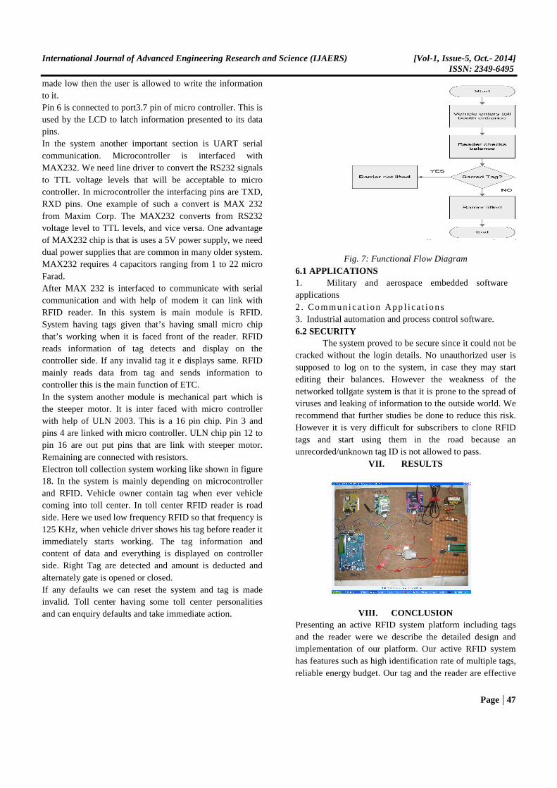
VI. FUNCTIONAL DESCRIPTION Presently toll collection system is mainly depending on the men. That means it is depending on human effort so in this proposal to reduce human effort and improve security and avoiding jam at toll center. This system is working like in shown figure 18, here we are using PIC16F877A microcontroller it is interfaced with LCD, steeper motor, RFID. The microcontroller has totally 40 pins . To display microcontroller is interred faced with LCD. In LCD 8 pins are data pins that are 7 to 14 are connected to port0 of microcontroller. These 8 pins are data pins. These are used to send information to LCD or read contents from LCD registers that are displayed on the LCD. Pin 4 in LCD to port 3.5 pin of micro controller pin 4 LCD is called register select pin. This is used to select the internal register of LCD, this pin is made low then the instruction command code register is selected. If this pin is made high then the data register is selected. Pin 5 is connected to pin 3.6 in micro controller. Pin5 of LCD is called read/write pin. If this pin is made high then the user is allowed to read information from it. If this pin is
International Journal of Advanced Engineering Research and Science (IJAERS) [Vol-1, Issue-5, Oct.- 2014] ISSN: 2349-6495
Page | 47
made low then the user is allowed to write the information to it. Pin 6 is connected to port3.7 pin of micro controller. This is used by the LCD to latch information presented to its data pins. In the system another important section is UART serial communication. Microcontroller is interfaced with MAX232. We need line driver to convert the RS232 signals to TTL voltage levels that will be acceptable to micro controller. In microcontroller the interfacing pins are TXD, RXD pins. One example of such a convert is MAX 232 from Maxim Corp. The MAX232 converts from RS232 voltage level to TTL levels, and vice versa. One advantage of MAX232 chip is that is uses a 5V power supply, we need dual power supplies that are common in many older system. MAX232 requires 4 capacitors ranging from 1 to 22 micro Farad. After MAX 232 is interfaced to communicate with serial communication and with help of modem it can link with RFID reader. In this system is main module is RFID. System having tags given that’s having small micro chip that’s working when it is faced front of the reader. RFID reads information of tag detects and display on the controller side. If any invalid tag it e displays same. RFID mainly reads data from tag and sends information to controller this is the main function of ETC. In the system another module is mechanical part which is the steeper motor. It is inter faced with micro controller with help of ULN 2003. This is a 16 pin chip. Pin 3 and pins 4 are linked with micro controller. ULN chip pin 12 to pin 16 are out put pins that are link with steeper motor. Remaining are connected with resistors. Electron toll collection system working like shown in figure 18. In the system is mainly depending on microcontroller and RFID. Vehicle owner contain tag when ever vehicle coming into toll center. In toll center RFID reader is road side. Here we used low frequency RFID so that frequency is 125 KHz, when vehicle driver shows his tag before reader it immediately starts working. The tag information and content of data and everything is displayed on controller side. Right Tag are detected and amount is deducted and alternately gate is opened or closed. If any defaults we can reset the system and tag is made invalid. Toll center having some toll center personalities and can enquiry defaults and take immediate action.
Fig. 7: Functional Flow Diagram 6.1 APPLICATIONS 1. Military and aerospace embedded software applications 2 . Commun ica t i on App l i ca t i ons 3. Industrial automation and process control software. 6.2 SECURITY The system proved to be secure since it could not be cracked without the login details. No unauthorized user is supposed to log on to the system, in case they may start editing their balances. However the weakness of the networked tollgate system is that it is prone to the spread of viruses and leaking of information to the outside world. We recommend that further studies be done to reduce this risk. However it is very difficult for subscribers to clone RFID tags and start using them in the road because an unrecorded/unknown tag ID is not allowed to pass.
VII. RESULTS
VIII. CONCLUSION Presenting an active RFID system platform including tags and the reader were we describe the detailed design and implementation of our platform. Our active RFID system has features such as high identification rate of multiple tags, reliable energy budget. Our tag and the reader are effective

International Journal of Advanced Engineering Research and Science (IJAERS) [Vol-1, Issue-5, Oct.- 2014] ISSN: 2349-6495
Page | 48
for development and evaluation of prototype applications because of the flexibility of the design of both hardware and software. So, our platform will be suitable for versatile item management applications.
IX. FUTURE SCOPE The future works include as follows:
• The investigation of cost reduction of the platform
• The sophisticated design of the collision arbitration of the active RFIDs.
REFERENCES [1] IET. 2009. Radio Frequency Identification Device
Technology (RFID), The Institution of Engineering and Technology, Available at: http://www.theiet.org/factfiles/it/rfidpage. cfm?type=pdf, Accessed on 15/06/12.
[2] Want, R. 2006. An Introduction to RED) Technology, IEEE Pervasive Computing, 5(1), pp. 25-33.
[3] Stanford, V. 2003. Pervasive computing goes the last hundred feet with RFID systems, IEEE Pervasive Computing, 2(2), pp 9–14.
[4] Soldatos, J., Kefalakis, N., Leontiadis, N. et al. 2010. Core ASPIRE Middleware Infrastructure (Final Version), ASPIRE Consortium, ID: WP3/D3.4b, Revision 1.9 http://www.fp7aspire.eu/fileadmin/aspire/docs/deliverables/ASPIRE_D3.4b_Final.pdf.
Websites Links: [5] http://www.fp7aspire.eu/fileadmin/aspire/docs/delivera
bles/ASPIRE_D3.4b_Final.pdf [6] http://www.arm.com/ [7] http://www.microchip.com [8] http://www.go-etc.jp/english/about/index.html