electronic traffic control device guidelines
TRANSCRIPT

Revision 05/07/21
MichiganDepartment ofTransportation
Electronic Traffic Control DeviceGuidelines
Electronic Traffic Control Device Guidelines 05/07/21
MDOTProjectWise\Documents\Reference Documents\Traffic Reference\Signals\Web\0-Operation Guides
Revision Date: Issue Addressed
8-4-15: Original posting to website
11-30-16: Corrected missing hyperlink to section 1.7.1 on pg. 10
Page 101 section 7.4.1 C under REST IN WALK: Added reference to section 7.5 E for Coordination Mode
Page 12 section 1.7 Devices in School Zones: Added verbiage that requests should be documented by aletter from the Superintendent, especially when school costs will be incurred with the installation
Page 16 Figure 1-2: Corrected step 4B verbiage
Pages 116-117 SECTION B – PREEMPT TIMES: SEL Ped Cl, SEL Yellow, SEL Red Cl: When replacing existingcontrollers (having EPAC Software versions prior to 3.56) with new controllers (using EPAC Softwareversion 3.56 or greater), it is imperative that any existing settings of SEL PED CLR = “0” be changed to SELPED CLR = “1” to avoid long transition times.
11-29-17: Page 8 Section 1.3 : Added text “including aligned left turn only lanes” when discussing the need towiden to obtain two approach lanes to accommodate a new traffic signal
Page 55 Section 5.2.1 Cycle Length Selection added: “The network cycle optimization option should beselected, and the resulting performance indices reviewed and reported as part of cycle length evaluationand selection.”
Section 1.2.6 Signals for Private development: Added typical data requirements for traffic impactstudies
Added verbiage about the purpose of this document immediately below this update list
05-07-21: Notification of Installation of New Traffic Signals (Formerly T&S Note224a) was added as Section 1.3
Financial Participation in Traffic Signals Due to Operational Changes (Formerly T&S Note 262A) wasadded as Section 1.5
Pedestrian Activated Devices information updated in Section 1.6 in regards to Rectangular RapidFlashing Beacons.
Additional references to Form 1597 (1597 Form Signal Study Screening) and Pedestrian Crosswalk Guidewere added in Section 3.1.
Section 7 was rearranged in descending order starting with the most commonly used TimingPermit. The NTCIP Permit was discussed in Section 7.1. Sections discussing the same timing permitwere also combined.
Reference to the EPAC timing parameters spreadsheet was added to Section 7.2.

Electronic Traffic Control Device Guidelines 05/07/21
MDOTProjectWise\Documents\Reference Documents\Traffic Reference\Signals\Web\0-Operation Guides
The purpose of the Electronic Traffic Control Device Guidelines is to provide guidelines and recommendations forthe use and operation of electronic traffic control devices in the state of Michigan. This manual providesguidance to administrative, engineering, and technical staff. Engineering practice requires that professionals usea combination of technical skills and judgment in decision making. Engineering judgment is necessary to allowdecisions to account for unique site-specific conditions and considerations to provide high quality products,within budget, and to protect the public health, safety, and welfare. This manual provides the generaloperational guidelines; however, it is understood that adaptation, adjustments, and deviations are sometimesnecessary. Innovation is a key foundational element to advance the state of engineering practice and developmore effective and efficient engineering solutions and materials. As such, it is essential that our engineeringmanuals provide a vehicle to promote, pilot, or implement technologies or practices that provide efficienciesand quality products, while maintaining the safety, health, and welfare of the public. It is expected whenmaking significant or impactful deviations from the technical information from these guidance materials, thatreasonable consultations with experts, technical committees, and/or policy setting bodies occur prior to actionswithin the timeframes allowed. It is also expected that these consultations will eliminate any potential conflictsof interest, perceived or otherwise. MDOT Leadership is committed to a culture of innovation to optimizeengineering solutions.
The National Society of Professional Engineers Code of Ethics for Engineering is founded on six fundamentalcanons. Those canons are provided below.
Engineers, in the fulfillment of their professional duties, shall:
1. Hold paramount the safety, health, and welfare of the public.2. Perform Services only in areas of their competence.3. Issue public statement only in an objective and truthful manner.4. Act for each employer or client as faithful agents or trustees.5. Avoid deceptive acts.
Conduct themselves honorably, reasonably, ethically and lawfully so as to enhance the honor, reputation, andusefulness of the profession.
To provide comments, please contact the MDOT Signals Unit at 517-488-7413.

Electronic Traffic Control Device Guidelines 05/07/21
MDOTProjectWise\Documents\Reference Documents\Traffic Reference\Signals\Web\0-Operation Guides
This document was prepared by: In cooperation with:
WSP USA Michigan Department of Transportation
500 Griswold Street, Suite 2600 Operations and Field Services DivisionDetroit, MI 48226 Traffic Signal Operations
6333 Lansing RdLansing, MI 48917

Electronic Traffic Control Device Guidelines 05/07/2021
MDOTProjectWise\Documents\Reference Documents\Traffic Reference\Signals\Web\0-Operation Guides
TABLE OF CONTENTS
TABLE OF CONTENTS .................................................................................................................................1
1 STUDY AND APPROVAL PROCESS FOR DEVICES ..................................................................................1
1.1 Requesting an Electronic Traffic Control Device (Formerly T&S Note 201B) .................... 2
1.2 Traffic Signal Warrant Analysis (Formerly T&S Note 201A).............................................. 3
1.2.1 Items for Consideration Regarding Volume Information ............................................ 4
1.2.2 Items for Consideration Regarding Delay Information ............................................... 4
1.2.3 Items for Consideration Regarding Crash Information ............................................... 5
1.2.4 Miscellaneous Items .................................................................................................. 5
1.2.5 Signal Warrant File Naming Convention .................................................................... 6
1.2.6 Signals for Private development ................................................................................ 6
1.3 Notification of Installation of New Traffic Signals (Formerly T&S Note 224A) .................. 8
1.3.1 Isolated or Outskirts Traffic Signals ............................................................................ 8
Traffic signals that are more than one mile from any other traffic signal or are the first traffic signalencountered when entering an area with signals spaced closer than one mile. ........................ 8
1.3.2 Non-Isolated Traffic Signals ....................................................................................... 9
1.4 Required Intersection Widening to Accommodate New Signals (Formerly T&S Note 202A) 9
1.5 Financial Participation in Traffic Signals Due to Operational Changes (Formerly T&S Note 262A) 9
1.6 Pedestrian Activated Devices (Formerly T&S Note 210A) .............................................. 10
1.6.1 Rectangular Rapid Flashing Beacons (RRFB) (Formerly T&S Note 212B) ................... 10
Application ........................................................................................................................ 11
Design ............................................................................................................................... 11
Operation.......................................................................................................................... 12
1.6.2 Pedestrian Hybrid Beacon ....................................................................................... 13
1.7 Sign Mounted Flashing Beacons (Formerly T&S Note 208B) .......................................... 13
1.8 Devices for Emergency Vehicles (Formerly T&S Notes 204A and 205B) ......................... 14
Electronic Traffic Control Device Guidelines 05/07/2021
MDOTProjectWise\Documents\Reference Documents\Traffic Reference\Signals\Web\0-Operation Guides
1.8.1 Traffic Signal for Emergency Vehicle Access ............................................................. 14
1.8.2 Auxiliary Devices for Emergency Vehicle Access ...................................................... 15
1.9 Devices in School Zones ............................................................................................... 16
1.9.1 School Sign Mounted Flashing Beacons (Formerly T&S Note 404C) .......................... 16
Operation.......................................................................................................................... 16
Operation Schedule ........................................................................................................... 17
Cost Participation .............................................................................................................. 17
Processing ......................................................................................................................... 17
Removal of Flasher ............................................................................................................ 18
1.10 Manual Traffic Signal Operation Using The Police Control Box .................................... 18
1.10.1 To hand direct traffic without the traffic signal: .................................................... 19
1.10.2 To give additional green time to one Movement:.................................................. 20
1.11 Temporary Traffic Signals........................................................................................... 22
1.11.1 Temporary Traffic Signals at Crossroads ................................................................ 22
1.11.2 Temporary Traffic Signals to Alternate Traffic in a Single Lane (Formerly T&S Note 906A) 22
1.12 Removal of Existing Traffic Signals ............................................................................. 23
2 LEFT-TURN PHASING GUIDELINES .................................................................................................... 25
2.1 Types of Left-Turn Phasing ........................................................................................... 25
2.2 When to Consider Left-Turn Phasing ............................................................................ 25
2.3 Determining Left-Turn Phasing Type............................................................................. 26
2.3.1 Permissive-Protected and Protected-Permissive Left-Turn Phasing.......................... 26
2.3.2 Protected-Only Left-Turn Phasing ............................................................................ 27
2.4 Removal of Existing Left-Turn Signal Phasing ................................................................ 28
3 PEDESTRIAN SIGNAL GUIDELINES .................................................................................................... 30
3.1 When to Install Pedestrian Signal Indications ............................................................... 30
3.2 How to Operate Pedestrian Signals .............................................................................. 31

Electronic Traffic Control Device Guidelines 05/07/2021
MDOTProjectWise\Documents\Reference Documents\Traffic Reference\Signals\Web\0-Operation Guides
3.3 Countdown Pedestrian Signals ..................................................................................... 31
3.4 Accessible Pedestrian Signals ....................................................................................... 31
4 SIGNAL TIMING CALCULATIONS....................................................................................................... 33
4.1 Vehicular Clearance Interval Calculations ..................................................................... 33
4.1.1 Yellow Change Intervals .......................................................................................... 33
4.1.2 All-Red Clearance Intervals ...................................................................................... 34
4.1.3 Boulevard Clearance Intervals ................................................................................. 36
4.2 Pedestrian Clearance Interval Calculations ................................................................... 37
4.2.1 Walk Intervals ......................................................................................................... 37
4.2.2 Pedestrian Clearance Time ...................................................................................... 37
4.3 Minimum Splits ............................................................................................................ 41
4.3.1 Minimum Green Intervals ....................................................................................... 41
4.3.2 Minimum Split Calculations ..................................................................................... 41
5 TRAFFIC MODELING ........................................................................................................................ 43
5.1 Map and Network Set-Up ............................................................................................. 43
5.1.1 File Structure and Naming Convention .................................................................... 44
5.1.2 Map Set-Up ............................................................................................................. 45
5.1.3 Basic Coding Parameters ......................................................................................... 45
Link Naming ...................................................................................................................... 45
Link Speed ......................................................................................................................... 46
Ideal Saturated Flow Rate ................................................................................................. 46
Volume Input .................................................................................................................... 46
Peak Hour Factor............................................................................................................... 47
Right and Left-Turn Lane Storage Distances ....................................................................... 47
Minimum Splits and Clearance Intervals ............................................................................ 48
Actuated Signal Settings .................................................................................................... 50

Electronic Traffic Control Device Guidelines 05/07/2021
MDOTProjectWise\Documents\Reference Documents\Traffic Reference\Signals\Web\0-Operation Guides
Inhibit Max Setting ............................................................................................................ 51
Interchanges ..................................................................................................................... 51
Parking Maneuvers ........................................................................................................... 51
Michigan Boulevard .......................................................................................................... 52
Travel Time ....................................................................................................................... 53
5.1.4 Intersection Numbering .......................................................................................... 53
5.1.5 Standard Intersection Phasing Set-Up ..................................................................... 54
5.1.6 Boulevard Phasing Set-Up ....................................................................................... 55
5.2 Optimization ................................................................................................................ 57
5.2.1 Split, Cycle Length, and Offset Selection .................................................................. 57
5.2.2 Zone Assignment ..................................................................................................... 60
5.2.3 Coordination with Adjacent Signals ......................................................................... 60
5.2.4 Phasing ................................................................................................................... 61
5.2.5 Measures of Effectiveness ....................................................................................... 61
5.2.6 Time-of-Day Schedules ............................................................................................ 62
5.2.7 Flash Schedules ....................................................................................................... 64
5.3 Microsimulation ........................................................................................................... 65
5.3.1 Simulation Timeframe ............................................................................................. 65
Network Seeding Period .................................................................................................... 65
Analysis Period .................................................................................................................. 66
5.3.2 Calibration and Validation ....................................................................................... 66
5.3.3 Measures of Effectiveness ....................................................................................... 67
5.4 DOCUMENTATION ....................................................................................................... 67
5.4.1 Project Benefits Analysis ......................................................................................... 67
5.4.2 Project Report ......................................................................................................... 69
Measures of Effectiveness Documentation ........................................................................ 69

Electronic Traffic Control Device Guidelines 05/07/2021
MDOTProjectWise\Documents\Reference Documents\Traffic Reference\Signals\Web\0-Operation Guides
Report Organization .......................................................................................................... 69
6 DATA COLLECTION .......................................................................................................................... 73
6.1 Traffic Counts and Peaking Characteristics ................................................................... 73
6.1.1 General Guidelines .................................................................................................. 73
6.1.2 24-Hour Volume Counts .......................................................................................... 74
6.1.3 Turning-Movement Counts ..................................................................................... 75
6.1.4 Pedestrian Counts ................................................................................................... 76
6.2 Gap Studies .................................................................................................................. 76
6.3 Delay/Queuing ............................................................................................................. 77
6.4 Speed Studies............................................................................................................... 77
6.5 Travel Time Data .......................................................................................................... 77
6.6 Intersection Geometry and Equipment ......................................................................... 77
6.6.1 Intersection Inventory and Condition Form ............................................................. 78
6.6.2 Intersection Photographs ........................................................................................ 78
6.7 Heavy Vehicle Volume .................................................................................................. 79
6.8 Bus Blockages............................................................................................................... 79
6.9 Parking Maneuvers ...................................................................................................... 80
6.10 Crash Data ................................................................................................................. 80
7 TIMING PLAN PREPARATION ........................................................................................................... 81
7.1 NTCIP Traffic Signal Timing Permit Form ....................................................................... 82
7.1.1 Basic NTCIP Timing Parameters ............................................................................... 82
Section A – Phase Description ........................................................................................... 83
Section B – Basic Vehicle Timings ...................................................................................... 83
Section C – Pedestrian Timing ........................................................................................... 84
Section D – Initialization and Actuation ............................................................................. 85
Section E – Daily Flash and Conflict Flash ........................................................................... 86

Electronic Traffic Control Device Guidelines 05/07/2021
MDOTProjectWise\Documents\Reference Documents\Traffic Reference\Signals\Web\0-Operation Guides
Section F – Event/Action Plan Set-Up ................................................................................ 86
Section G – Less Frequently Used Features ........................................................................ 87
Section H – VEHICLE Overlaps............................................................................................ 87
7.1.2 Advanced Timing Parameters Form – NTCIP Permit ................................................. 88
7.1.3 Scheduling Information – NTCIP Permit ................................................................... 92
Section A – Typical Schedule ............................................................................................. 93
Section B – Special Schedules ............................................................................................ 93
Section C – Special Schedules Grid..................................................................................... 94
7.1.4 Preemption Information Form – NTCIP Permit ........................................................ 94
7.2 EPAC CONTROLLER UNIT ............................................................................................ 100
7.2.1 Basic Timing Parameters Form - EPAC Controller Unit ........................................... 100
Section A – Phase Description ......................................................................................... 101
Section B – Basic Vehicle Timings .................................................................................... 101
Section C – Pedestrian Timing ......................................................................................... 102
Section D – Initialization and Actuation ........................................................................... 103
Section E – Non-Lock Memory/Dual Entry ....................................................................... 105
Section F – Dial-Split Set-Up ............................................................................................ 106
Section G – Hours of Operation and Additional Remarks ................................................. 107
Section H – Phase Overlaps ............................................................................................. 107
7.2.2 Advanced Timing Parameters Form – EPAC Controller ........................................... 108
7.2.3 Preemption Information Form – EPAC Controller .................................................. 117
7.3 EPIC/EF-140 CONTROLLER UNITS................................................................................ 123
7.3.1 Basic Timing Parameters Form – EPIC/EF-140 Controller Units .............................. 123
Pre-timed EPIC/EF-140 Controller Timing Permit ............................................................. 123
Actuated EPIC/EF-140 Controller Timing Permit .............................................................. 129
7.3.2 ADVANCED TIMING Parameters Form – EPIC/EF-140 Controller ............................ 135
Electronic Traffic Control Device Guidelines 05/07/2021
MDOTProjectWise\Documents\Reference Documents\Traffic Reference\Signals\Web\0-Operation Guides
7.3.3 Preemption Information Form – EPIC/EF-140 Controller ....................................... 139
7.4 Standard Information: Page 1 ..................................................................................... 144
Section 1 – Remarks ........................................................................................................ 144
Section 2 – Flash Operation ............................................................................................. 144
Section 3 – Preemption ................................................................................................... 145
Section 4 – Controller Type ............................................................................................. 145
Section 5 – Location Information ..................................................................................... 145
7.5 Standard Information: Page 2 ..................................................................................... 146
Section 1 – Signal System Information ............................................................................. 146
Section 2 – Vehicular and Pedestrian Detection............................................................... 148
Section 3 – Disappearing Legend Case Signs .................................................................... 149
Section 4 – Remarks ........................................................................................................ 149
Section 5 – Location ........................................................................................................ 149
8 TIMING PLAN IMPLEMENTATION .................................................................................................. 149
8.1 Field Adjustments ...................................................................................................... 150
8.2 Verification That Signal Timing Has Been Installed ...................................................... 151
List of Appendices
Appendix A – MDOT Traffic Volume Data Submittal Format
Appendix B – Intersection Inventory and Condition Form
Appendix C – Sample Timing Permit Forms
Appendix D – Synchro and SimTraffic Sample Analysis Report Formats
Appendix E – Sample Benefit Cost Analysis Spreadsheet
List of Figures
Figure 1-1: Example of RRFB with W1-2 sign and W16-7p plaque at crosswalk across uncontrolled approach.[Photo courtesy of City of St. Petersburg, Florida] .................................................................. 10

Electronic Traffic Control Device Guidelines 05/07/2021
MDOTProjectWise\Documents\Reference Documents\Traffic Reference\Signals\Web\0-Operation Guides
Figure 1-2: Hand Direct Traffic Without The Traffic Signal ....................................................... 19
Figure 1-3: Give Additional Green Time to One Movement ..................................................... 20
Figure 1-4: Contact Information for each MDOT Region ......................................................... 21
Figure 4-1: Measuring Intersection Width .............................................................................. 36
Figure 4-2: Measuring Pedestrian Crossing Distances ............................................................. 39
Figure 5-1: Crossover Peak Hour Factor .................................................................................. 47
Figure 5-2: Turn Lane Distances .............................................................................................. 48
Figure 5-3: Phasing Window for Signal with Pedestrian Push-Buttons and No Ped-Calls .......... 49
Figure 5-4: Parking Maneuvers Coding Examples .................................................................... 51
Figure 5-5: Typical Boulevard Configuration ........................................................................... 52
Figure 5-6: Boulevard Node Numbering.................................................................................. 53
Figure 5-7: Standard Boulevard Phasing Assignments ............................................................. 55
Figure 5-8: Trail Green Sequence ............................................................................................ 56
Figure 5-9: Example Timing Plan Changes by Time-of-Day ...................................................... 63
Figure 5-10: Example SimTraffic Time Interval Setup .............................................................. 66
Figure 5-11: Sample Model Validation Log .............................................................................. 67
Figure 6-1: Tube Counters on Boulevards ............................................................................... 75
Figure 7-1: EPIC/EF-140 Pre-Timed Permit Example .............................................................. 123
Figure 7-2: EPIC/EF-140 Actuated Timing Permit Example .................................................... 130
Figure 7-3: Typical Multi-Path Operation Sequence .............................................................. 133
Figure 7-4: Advanced Timing Parameters Form (EPIC) Example ............................................ 135
Figure 7-5: EPIC/EF-140 Preemption Information Form ........................................................ 139
Figure 7-6: EPAC Timing Permit Example .............................................................................. 144
Figure 7-7: Advanced Timing Parameters Form (EPAC) Example ........................................... 144
Figure 7-8: Dual-Ring Controller (NEMA Standard) ............................................................... 144
Figure 7-9: Permissive Coordination Mode Example ............................................................. 144

Electronic Traffic Control Device Guidelines 05/07/2021
MDOTProjectWise\Documents\Reference Documents\Traffic Reference\Signals\Web\0-Operation Guides
Figure 7-10: Yield Coordination Mode Example .................................................................... 144
Figure 7-11: EPAC Preemption Information Form ................................................................. 144
Figure 8-1: Traffic Signal Timing Record ................................................................................ 151
List of Tables
Table 5-1: Warrant 1 (Minimum Vehicular Volume) ............................................................................................ 64Table 5-2: Comparison of Optimized and Existing Intersection Operations - Zone 1, PM Peak Hour ................... 69Table 5-3: Comparison of Optimized and Existing Network Operations - Zone 1, PM Peak Hour ........................ 69Table 7-1: Signal Timing Permit Ranges and Increments ................................................................................. 101Table 7-2: Extended Pedestrian Clearance Codes and Descriptions ................................................................ 103Table 7-3: Initialization Codes and Descriptions ............................................................................................... 104Table 7-4: Non-Actuated Response Codes and Descriptions............................................................................ 104Table 7-5: Vehicle Recall Codes and Descriptions ........................................................................................... 104Table 7-6: Pedestrian Recall Codes and Descriptions ...................................................................................... 105Table 7-7: Phase Mode Codes and Descriptions .............................................................................................. 106Table 7-8: Advanced Timing Parameters Ranges and Increments .................................................................... 108Table 7-9: Coordination Mode Codes and Descriptions .................................................................................... 112Table 7-11: Maximum Mode Codes and Descriptions ....................................................................................... 114Table 7-11: Correction Mode Codes and Descriptions ...................................................................................... 116Table 7-12: EPIC and EF-140 Signal Timing Permit Ranges and Increments ................................................... 124Table 7-13: Actuation Codes and Descriptions ................................................................................................. 130Table 7-14: Advanced Timing Parameters Ranges and Increments .................................................................. 136
Electronic Traffic Control Device Guidelines 05/07/2021
MDOTProjectWise\Documents\Reference Documents\Traffic Reference\Signals\Web\0-Operation Guides | 1
1 STUDY AND APPROVAL PROCESS FOR DEVICES
This chapter provides guidance for evaluating various electrical devices proposed for use as traffic controldevices or as warning devices on State of Michigan highways.
The following MDOT Traffic & Safety Notes have been incorporated into this chapter:
§ Note 201A: Traffic Signal Warrant Analysis
§ Note 201B: Requesting an Electronic Traffic Control Device
§ Note 202A: Required Intersection Widening to Accommodate New Signals
§ Note 204A: Guidelines for Installation of Emergency Vehicle Traffic Signals
§ Note 205B: Guidelines for Installation of Emergency Vehicle Advance Warning Signs Supplemented withFlashers or Pre-empt of Existing Traffic Signals.
§ Note 210A: Application of the MMUTCD Traffic Signal Warrants
§ Note 211A: Procedure for Installing a Pedestrian Hybrid Beacon
§ Note 212B: Signs with Rectangular Flashing Beacons
§ Note 224A: Notification of Installation of New Traffic Signals
§ Note 262A: Financial Participation in Traffic Signals Due to Operational Changes
§ Note 405B: School Traffic Signals
Consideration of all transportation modes, and advances in technology, have resulted in more devices beingrequested to assist pedestrians, cyclists, bus and transit, in addition to automobile drivers. When evaluating aproposed device for the benefit of one of these modes of transportation, consideration must be given topotential adverse impacts to the other modes. A comprehensive traffic engineering study is required toevaluate requests for new devices and for the modification of existing devices.
The process for approving or modifying an existing electronic traffic control device on the state trunklinehighway system can be broken down into two major parts, the study and the design. This chapter will focus onthe Signal Study with emphasis on the approval process. In addition to standard traffic signals, these devicesinclude overhead flashing beacons, sign mounted flashers, and various devices to assist pedestrians andemergency vehicles

Electronic Traffic Control Device Guidelines 05/07/2021
MDOTProjectWise\Documents\Reference Documents\Traffic Reference\Signals\Web\0-Operation Guides | 2
1.1 REQUESTING AN ELECTRONIC TRAFFIC CONTROL DEVICE (FORMERLY T&SNOTE 201B)
Some requests for new electronic traffic control devices can be addressed by a preliminary review of existingdata and roadway characteristics without ordering a traffic survey and a full traffic engineering study. To assistin this preliminary review of data, the online SIGNAL STUDY SCREENING FORM has been developed. To ensurethe proper use of electronic traffic control devices, MDOT has a process for studying and approving thesedevices outlined as follows:
1. The Region/TSC Traffic and Safety Representative receives a request to review a location for an electricaldevice.
2. The Region/TSC Traffic and Safety Representative reviews the existing files and conducts a field review.The Region/TSC Traffic and Safety Representative completes the online SIGNAL STUDY SCREENINGFORM (1597) and submits it to the MDOT Signals Unit. Some preliminary counts may be required tocomplete this form. Although the title of this form refers to “Signal”, this form should be used forrequests for all electronic traffic control devices. The comments section of this form should be used toclearly state the request and to include any detailed information pertinent to the issue.
3. The MDOT Signals Unit will review the form and decide if a formal study is required, if more informationis needed, or if the request can be denied based on the information in the Signal Study Screening form.
4. If a formal study is needed, the MDOT Signals Unit will typically order a full survey of the intersection tobe completed typically by Transportation Planning Staff. For a new signal study, the full survey includes24-hour machine counts, 8-hour manual turning movement counts, a gap study, and a delay study. Inaddition, they will provide a drawing of the intersection showing laneage and any other unusualconditions.
5. The MDOT Signals Unit will also review the crash data for the intersection and if appropriate conduct afield review.
6. Upon completion of the full survey, review of the crash data, and if appropriate a field review of thelocation, the MDOT Signals Unit will determine if a signal should be installed. The Region/TSC Traffic andSafety Representative is asked for input on the draft memo and will receive the final memo of theresults. The Region/TSC Traffic and Safety Representative then notifies the local agency involved of theresults.
7. The Region/TSC Traffic and Safety Representative then notifies any affected local or private agency ofthe results. Because traffic signal maintenance (and sometimes installation) costs are split among anyagencies having jurisdiction of an approach to the intersection, The Region/TSC Traffic and SafetyRepresentative must provide written approval from any agencies ensuring that the estimated signalcosts will be paid.
8. For permit based requests, the developer shall hire a consultant pre-qualified in traffic signal operationsto perform the analysis. MDOT reserves the right to make the final determination if electronic trafficcontrol devices are justified. If a device is approved as part of a permit, a minimum $2000.00 fee (per

Electronic Traffic Control Device Guidelines 05/07/2021
MDOTProjectWise\Documents\Reference Documents\Traffic Reference\Signals\Web\0-Operation Guides | 3
signal location) must be included in the permit to cover MDOT’s cost to set up the controller andperform inspections on the installation. The permitee is typically responsible for the installation costsand for obtaining approvals from any other agencies involved.
1.2 TRAFFIC SIGNAL WARRANT ANALYSIS (FORMERLY T&S NOTE 201A)
This section provides information and guidance on the use of traffic signal warrants. MDOT has an onlinespreadsheet SIGNAL WARRANTS.XLS to assist in summarizing the necessary data and performing signal warrantanalysis.
The online MDOT document TRAFFIC SIGNALS - A GUIDE FOR THEIR PROPER USE explains the need to useuniform standards when evaluating the need for a traffic signal and the potential negative impacts of installing atraffic signal.
The Michigan Manual on Uniform Traffic Control Devices (MMUTCD) contains a number of “warrants” of whichat least one must be met prior to installing a traffic signal. A significant amount of data must be gathered andevaluated to properly determine if a traffic signal is appropriate. Even if one of the warrants is met, engineeringjudgment is required to determine if the benefits of the installation of a traffic signal will outweigh the negativeimpacts. It is also important to review the traffic signal warrants for existing traffic signals periodically todetermine if a traffic signal is still justified. Unwarranted signals can actually increase both delay and crashes.Also, the Federal Highway Administration (FHWA) will not fund work at traffic signals that do not meet warrants.
For a more detailed description of each signal warrant see Chapter 4C: Traffic Control Signal Needs Studies in thecurrent version of the MMUTCD. MDOT primarily focuses on Warrant 1 Condition A, but all appropriatewarrants should be evaluated to ensure a comprehensive review of site conditions.
An engineering study focusing on traffic conditions, non-motorized characteristics, and physical characteristicsof the location should be performed before determining the justification of a particular signal. Compliance with(or lack of) the traffic signal warrants does not in itself require the installation (or removal) of a traffic controlsignal.
A warrant analysis for a new signal requires the following data:
§ Peak eight hour manual turning movement volume
§ A backup delay study per MDOT standards
§ A gap study per MDOT standards
§ Twenty four hour machine volumes on all approaches
§ An intersection diagram showing all pertinent geometric information and speed limits
§ Crash data from the most recent 3 to 5 years

Electronic Traffic Control Device Guidelines 05/07/2021
MDOTProjectWise\Documents\Reference Documents\Traffic Reference\Signals\Web\0-Operation Guides | 4
§ If appropriate, pedestrian and school crossing data
§ If appropriate, a capacity analysis comparing the existing operation and potential signalized operation
It is important to review all criteria in each warrant. Some require trial of other remedial measures and severalhave delay or crash data requirements. Optimization projects will typically provide all the required data as partof the project.
1.2.1 ITEMS FOR CONSIDERATION REGARDING VOLUME INFORMATION
§ The MMUTCD states, “The study should consider the effects of the right-turn vehicles from the minor-street approaches.” This addresses the “right turn on red” phenomena. Effects of left turning vehicleson one way roads (boulevards and cross-overs) can be considered for reducing approach volumes.
§ The MMUTCD allows for consideration of crashes, speed limits and area population for reducing volumerequirements. While the MMUTCD allows for it, the reductions are not typically treated as additive fortypical warrant analyses. Whichever situation creates a larger reduction in the warranting volumes istypically used.
Ø If a situation arises where the engineer feels that it is appropriate to use multiple reductions inan additive fashion, she or he should consult with the Signals Unit for agreement and approvalprior to submitting a recommendation.
§ All warrants will be analyzed based on two lane approaches in all directions. A minimum of twoapproach lanes is required prior to installing a traffic signal.
1.2.2 ITEMS FOR CONSIDERATION REGARDING DELAY INFORMATION
§ When reviewing delay information at an intersection, patterns of delay in excess of one minuteexperienced by any particular approach may be a cause for concern.
Ø On corridors with large cycle lengths, the maximum delay may be higher just based on the splitsprovided for each movement. For example, a 120 second cycle length could consistently providethe major road with 90 seconds out of the cycle. A vehicle on the minor road that arrives justafter the signal turns red could experience over a minute delay with a traffic signal. In thatsituation the maximum delay considered typically would increase to account for the high cyclelength.
§ Field measured delay is the preferred data to be used for analysis. Locations where projected volumesare used have delay information calculated from simulation models. The simulation models must bereviewed carefully due to the speculative nature of volume projections.

Electronic Traffic Control Device Guidelines 05/07/2021
MDOTProjectWise\Documents\Reference Documents\Traffic Reference\Signals\Web\0-Operation Guides | 5
1.2.3 ITEMS FOR CONSIDERATION REGARDING CRASH INFORMATION
§ Crashes considered correctable by signalization are typically right angle type crashes. Research hasshown that total crashes typically increase when a signal is installed, particularly rear end type crasheson the major road. Locations that experience a pattern of right angle type crashes of at least 5 per yearon average may be a cause for concern and further review should be done to identify potential causes ofthe crashes. Also, crash trends over time and crash severity should be considered in determining if thenumber of crashes per year is a concern.
1.2.4 MISCELLANEOUS ITEMS
§ The MMUTCD states, “The satisfaction of a warrant or warrants shall not in itself require theinstallation of a traffic control signal.” A traffic signal should not be installed unless an identifiableconcern exists, regardless of any warrants that are met. The most important concerns are excessivedelays or crash patterns susceptible to correction by signalization.
§ The MMUTCD is referenced by the Michigan Vehicle Code and has the force of law. It states, “A trafficcontrol signal should not be installed unless one or more of the factors described in this Chapter aremet.” Federal funds cannot be used unless a warrant is met. Therefore, a thorough signal warrantanalysis must be completed before a traffic signal will be approved.
§ The MDOT Signals Unit considers Warrant #1 (Condition A) as the major component for trafficsignalization analysis. This warrant is an eight hour volume warrant. The remaining warrants weredeveloped to address situations when a location experiences a delay or crash pattern so serious that atraffic signal may be an appropriate solution even though the intersection does not meet the minimumvolumes required by Warrant #1 (Condition A). In those situations, other warrants may be considered.
§ Many of the warrants have multiple requirements that must be met before that warrant can be appliedto a location. Some [#1 (Condition B) and #3] require excessive delay be experienced on the minor roadapproaches and Warrant #1 (Combination of A & B) requires trial of other remedial measures first. Ifthese initial requirements are not met, it is inappropriate to review the remainder of the warrant.
§ Even if an intersection meets one of the warrants based on traffic data, engineering judgement isrequired to determine if a new traffic signal is the best solution. Considerations should include:Ø Evaluation of other alternatives including roundabouts, pedestrian devices, improved access
management, and roadway geometric improvements that may provide a better solution.Ø Assessing if the benefits of a traffic signal will outweigh any potential negative impacts including
increased delay and frequency of rear end crashes.Ø Determine the impact to any nearby signals. Signal spacing has significant impacts to traffic
operations along a corridor. Allowing a signal to be installed too close to an existing signal canresult in queues that may block all traffic movement at an intersection. Allowing a signal to be
Electronic Traffic Control Device Guidelines 05/07/2021
MDOTProjectWise\Documents\Reference Documents\Traffic Reference\Signals\Web\0-Operation Guides | 6
installed too close to existing signals along a corridor can interrupt two-way progression andsignificantly increase delay along the corridor. Minimum desirable signal spacing to providetwo-way progression (for cycle length of 90 s and 40 Mph speed) is approximately 1/2 mile.
Ø Evaluate existing roadway geometry that might preclude the installation of a traffic signalincluding horizontal and vertical curvature and skew.
1.2.5 SIGNAL WARRANT FILE NAMING CONVENTION
Each signal warrant analysis spreadsheet (SIGNAL WARRANTS.XLS) should adhere to a standard namingconvention unless otherwise discussed in advance with the MDOT project manager. The following is thestandard file naming convention:
Control Section # - Spot # -“Signal Warrant” – Month-Day-Year.xls
Example: The Woodward Avenue (M-1) corridor within the city of Detroit (Control Section 82400) is beingreviewed. The spot number in this case is 025. The date is May 6th, 2015.
File Name = 82400-025-Signal Warrant – 05-06-2015.xls
1.2.6 SIGNALS FOR PRIVATE DEVELOPMENT
If a traffic impact study is required per TRAFFIC & SAFETY NOTE 607C it is strongly suggested that a trafficvolume assumptions memo be approved very early in the study. This memo would include assumptionsregarding traffic growth, future year(s) to be evaluated, trip generation rates, percent bypass trips, and percentinternal trips.
The scope and detailed requirements of any required traffic impact study will be determined by a cooperativeeffort between MDOT (including specialty units) and the developer after a preliminary site plan has beensubmitted. Typical data requirements include the following:
§ Traffic data should have been collected within the last 3 years
§ Traffic data should be collected during the peak season (especially important if location is recreational innature). If not, contact MDOT planning to determine if counts can be adjusted using seasonal day ofweek (DOW) factors
§ The raw traffic counts should be included in the appendix
§ Growth rates should come from the urban travel demand model or statewide model. If not, the annualgrowth rate selected for use shall be subject to approval by MDOT staff
§ Pass-by and internal linked trips should be based on guidelines from the latest edition of the ITE TripGeneration Manual

Electronic Traffic Control Device Guidelines 05/07/2021
MDOTProjectWise\Documents\Reference Documents\Traffic Reference\Signals\Web\0-Operation Guides | 7
§ If development is anticipated to occur in phases, then the first phase (opening day) must be analyzed inaddition to total build out. If there are other intermediate phases prior to total build out, these may alsorequire separate analyses
§ If development generates 500 or more trips in the peak hour, a minimum 5-year horizon forecast mustbe included. This means total traffic (background + development) forecasted at least 5 years beyondopening year.
o 500 peak hour trips (In+Out) after reductions for by-pass tripso If development has an opening day and a future buildout, then the future buildout can serve as
the 5 year horizon forecast (only if the future buildout is at least 5 years after opening day)
To assist in determining the need for and the scope of traffic impact studies, the following online document wasprepared in 1994 for the Tri-County Regional Planning Commission in cooperation with the MichiganDepartment of Transportation and the Southeast Michigan Council of Governments (SEMCOG): “EVALUATINGTRAFFIC IMPACT STUDIES”.
A signal is often requested prior to the opening day of a private development. Use of the ITE trip generationmanual is the common method used to estimate peak hour development traffic. Often, the permit applicant willjustify a new signal using warrant #3 which is a peak hour warrant. Due to the speculative nature of thesevolume estimates, they must be reviewed closely. There are a few things that can be done to ensure a signal isonly installed if appropriate:
§ If it is a development where data could be collected at a similar installation (similar community andsimilar size development), have the development provide volume information from the existing opendevelopment. With that information, Warrant #1 (Condition A) may be reviewed.
§ For MDOT to consider approving a new signal prior to opening day of a development, one of the 8 hourwarrants must typically be shown to be met using volumes from a similar development.
§ Projected volumes are very speculative and it is not unusual for the projected and actual volumes tovary widely. As a result, the preferred option is to put language in the permit that requires thedevelopment to open and then a study be conducted with actual field data. Include time frames forwhen the study will be conducted and clearly state the developer will be responsible for all costs todesign and install the traffic signal if it is approved. The MDOT Signals Unit will still make the finaldetermination if a signal should be installed.
§ The peak hours can be modeled such that the operation can be reviewed with and without a signal inplace. It is preferred that the modeling be done with Synchro and electronic copies of the model besupplied to streamline the review process.
Electronic Traffic Control Device Guidelines 05/07/2021
MDOTProjectWise\Documents\Reference Documents\Traffic Reference\Signals\Web\0-Operation Guides | 8
§ Contact MDOT Signal Operations to confirm the scope of data collection and signal modeling includinggap study, 8 hour turning movement counts, and 24 hr road tube counts.
§ Use and provide appropriate MDOT online spreadsheets for analysis and evaluation.
1.3 NOTIFICATION OF INSTALLATION OF NEW TRAFFIC SIGNALS (FORMERLYT&S NOTE 224A)
This section provides information and guidance to alert motorists on the installation of new traffic signals. Allnew traffic signals shall be operated in a flashing mode for approximately one week before beginning “Stop-and-Go” operation.
To publicize the new traffic signal, a note will be included in all new “Stop-and-Go” traffic signal workauthorizations, requesting the installing agency to inform the Region/TSC Traffic and Safety Representative atleast two weeks in advance of installation. The Region/TSC Traffic and Safety Representative will then issue anannouncement to the appropriate people. (City Manager, Police Chief, State Police, newspaper, radio station,etc.)
Sample Announcement:
NOTIFICATION OF INSTALLATION OF NEW TRAFFIC SIGNAL
The MDOT will be installing a new stop-and-go traffic signal at intersection in city/township/countyduring the week of month, Monday date and year. The signal will operate in a flashing mode forapproximately one week before beginning STOP-AND-GO operation. For further information, please callthe MDOT Region Office in city at Phone number.
The conditions below, for isolated and non-isolated traffic signals, apply only to the roadways that did not stopprior to signalization. W3-3 signs may be erected on the minor legs if deemed appropriate.
1.3.1 ISOLATED OR OUTSKIRTS TRAFFIC SIGNALS
TRAFFIC SIGNALS THAT ARE MORE THAN ONE MILE FROM ANY OTHERTRAFFIC SIGNAL OR ARE THE FIRST TRAFFIC SIGNAL ENCOUNTERED WHENENTERING AN AREA WITH SIGNALS SPACED CLOSER THAN ONE MILE.
§ SIGNAL AHEAD symbol signs (W3-3) should be considered at the appropriate distance in advance of theintersection as determined by the Michigan Manual of Uniform Traffic Control Devices (MMUTCD) or ata greater distance as determined by engineering judgment. A permanent panel with the name of thecrossroad may be attached under the W3-3 sign.
Electronic Traffic Control Device Guidelines 05/07/2021
MDOTProjectWise\Documents\Reference Documents\Traffic Reference\Signals\Web\0-Operation Guides | 9
§ NEW SIGNAL AHEAD signs with a supplemental panel, ½ MILE (or other distance if appropriate), shouldbe considered in advance of the W3-3 sign. This sign should be removed approximately 90 days after thesignal is installed.
§ All signing should be supplemented with fluorescent orange flags to be removed after 90 days.
§ Battery operated flashers may be considered to supplement the signs. All supplemental devices shouldbe removed after approximately 90 days.
1.3.2 NON-ISOLATED TRAFFIC SIGNALS
Traffic signals along a corridor where the spacing is less than one mile.
§ If visibility limited or the signal is not expected some or all of the signing for Isolated Traffic Signalsshould be considered.
§ W3-3 signs with fluorescent flags should be erected. If visibility is not limited, this signing should beremoved after 90 days.
1.4 REQUIRED INTERSECTION WIDENING TO ACCOMMODATE NEW SIGNALS(FORMERLY T&S NOTE 202A)
When a “Stop-and-Go” traffic signal is installed at an intersection, the capacity of the through roadway isreduced by about half. In addition, left turning traffic can interlock, effectively stopping all through traffic. As aresult, prior to the installation of a “Stop-and-Go” traffic signal, all legs of the intersection should have aminimum of two approach lanes. Additional widening may be required to provide for capacity. An alternative towidening would be to prohibit left turns or provide for one way streets.
If widening is required, it shall be done in accordance with MDOT Geometric Design Guides, and the crossroadshall provide a minimum of two approach lanes. The crossroad widening shall be the responsibility of andfinanced by the roadway authority.
At locations with a single approach lane, intersection widening will typically be required in order to obtain twoapproach lanes, including aligned left turn only lanes, as required to accommodate a new traffic signal.
1.5 FINANCIAL PARTICIPATION IN TRAFFIC SIGNALS DUE TO OPERATIONALCHANGES (FORMERLY T&S NOTE 262A)
When an operational change to a traffic signal is required due a project not initiated by the department, such aswidening of a local road crossing a trunkline or signal modifications due to a development, all costs associatedwith the modifications shall be at the cost of the local governmental agency or the developer.

Electronic Traffic Control Device Guidelines 05/07/2021
MDOTProjectWise\Documents\Reference Documents\Traffic Reference\Signals\Web\0-Operation Guides | 10
Figure 1-1: Example of RRFB with W11-2 sign andW16-7p plaque at unsignalized crosswalk.[Photo courtesy of City of St. Petersburg, Florida]
If the controller is not adequate to handle the new operation or if the controller is 10 years old or older, thecontroller along with the cabinet will be replaced at no cost to the department.
All requests of this type should be processed as a permit to work within MDOT Right-of-Way.
The Traffic Signals Unit will assign costs due to operation changes.
1.6 PEDESTRIAN ACTIVATED DEVICES (FORMERLY T&S NOTE 210A)
This section provides information and guidance on the use of pedestrian activated electronic devices includingthe Rectangular Rapid Flashing Beacon (RRFB) and the pedestrian hybrid beacon (PHB). The PHB is oftenreferred to as a HAWK signal and is intended as an alternative when the warrants for a full pedestrian trafficsignal are not met, but additional traffic control beyond signing and pavement markings are desirable. The PHBsignal provides a protected walk movement but during the Flashing Don’t Walk, the vehicle traffic is shown aflashing red to minimize delay.
Relevant documents include the MMUTCD, which has a chapter for PHB’s, and MDOT’s online document:GUIDANCE FOR INSTALLATION OF PEDESTRIAN CROSSWALKS ON MICHIGAN STATE TRUNKLINE HIGHWAYS,which establishes minimum criteria for the consideration of a PHB or an RRFB. The criteria include pedestrianand vehicular volumes, the number of multiple threat lanes, the width of the crossing, and the traffic speed.
If minimum criteria are met for consideration of a PHBor an RRFB, then a signal study screening form can besent to the signals unit to initiate an engineering studyper Section 1.1
MDOT’s online spreadsheet, SIGNAL WARRANTS.XLScontains tabs for evaluating thresholds (not warrants)for both RRFB’s and PHB’s.
1.6.1 RECTANGULAR RAPID FLASHINGBEACONS (RRFB) (FORMERLY T&S NOTE212B)
Rectangular rapid flashing beacons (RRFB) used inconjunction with pedestrian crossing or schoolcrossing signs can alert drivers that a pedestrian maybe entering the crosswalk. The RRFB is intended toprovide emphasis to the crossing signs where driversmay not be expecting pedestrians, or where specialemphasis is required. The RRFB is a pedestrianactuated device, which is an essential aspect of its
Electronic Traffic Control Device Guidelines 05/07/2021
MDOTProjectWise\Documents\Reference Documents\Traffic Reference\Signals\Web\0-Operation Guides | 11
effectiveness.
The decision to use an RRFB must be based on engineering analysis of the site conditions. MDOT guidancedocuments for establishing pedestrian crossings and determining appropriate treatments include GUIDANCEFOR INSTALLATION OF PEDESTRIAN CROSSWALKS ON MICHIGAN STATE TRUNKLINE HIGHWAYS and TRAFFICAND SAFETY NOTE 401D “Uncontrolled Non-Motorized Crosswalks”. This MDOT guideline follows and uses textdirectly from FHWA Interim Approval 21 – Rectangular Rapid-Flashing Beacons at Crosswalks.
APPLICATION
1. An RRFB shall only be installed to function as a pedestrian-actuated conspicuity enhancement.
2. An RRFB shall only be used to supplement a post-mounted W11-2 (Pedestrian), S1-1 (School), or W11-15(Trail) crossing warning sign with a diagonal downward arrow (W16-7p) plaque, or an overhead-mounted W11-2, S1-1, or W11-15 crossing warning sign, located at or immediately adjacent to anuncontrolled marked crosswalk.
3. The RRFB is to be used at mid-block pedestrian crossings or pedestrian crossings at intersectionapproaches that are not controlled by another traffic control device (e.g. YIELD signs, STOP signs,Pedestrian Hybrid Beacon or traffic control signals). The RRFB may be applicable to a crosswalk acrossthe approach to, or egress from, a roundabout.
4. If sight distance approaching the crosswalk at which RRFBs are used is less than deemed necessary, anadditional RRFB may be installed in advance of the crosswalk to supplement a W11-2, S1-1, or W11-15crossing warning sign with an AHEAD (W16-9P) or distance (W16-2P or W16-2aP) plaque.
DESIGN
1. For design details please see MDOT’s online RECTANGULAR RAPID FLASHING BEACON special detail.
2. The outside edges of the RRFB indications, including any housings, shall not project beyond the outsideedges of the W11-2, S1-1, or W11-15 sign.
3. As a specific exception to MMUTCD Section 4L.01 guidance, the RRFB unit associated with a post-mounted sign and plaque may be located between the bottom of the crossing warning sign and the topof the supplemental downward diagonal arrow plaque (or, in the case of a supplemental advance sign,the AHEAD or distance plaque) or within 12 inches above the crossing warning sign, rather than 12inches minimum above or below the sign assembly.
4. For any approach on which RRFBs are used, two W11-2, S1-1, or W11-15 crossing warning signs (eachwith RRFB and W16-7p plaque) shall be installed at the crosswalk, one on the right-hand side of theroadway and one on the left-hand side of the roadway. On a divided highway, the left-hand sideassembly should be installed on the median, if practical, rather than on the far left side of the highway.
5. An RRFB shall not be installed independent of the crossing signs for the approach the RRFB faces. TheRRFB shall be installed on the same support as the associated W11-2 (Pedestrian), S1-1 (School), or
Electronic Traffic Control Device Guidelines 05/07/2021
MDOTProjectWise\Documents\Reference Documents\Traffic Reference\Signals\Web\0-Operation Guides | 12
W11-15 (Trail) crossing warning sign and plaque. If the RRFB unit is supplementing an overhead-mounted sign, the RRFB unit shall be mounted directly below the bottom of the sign.
OPERATION
1. The RRFB shall be normally dark, shall initiate operation only upon pedestrian actuation, and shall ceaseoperation at a predetermined time after the pedestrian actuation or, with passive detection, after thepedestrian clears the crosswalk.
2. All RRFBs associated with a given crosswalk shall, when activated, simultaneously commence operationof their alternating rapid flashing indications and shall cease operation simultaneously.
3. If pedestrian pushbuttons (rather than passive detection) are used to actuate the RRFBs, a pedestrianinstruction sign with the legend PUSH BUTTON TO TURN ON WARNING LIGHTS should be mountedadjacent to or integral with each pedestrian pushbutton.
4. The duration of a predetermined period of operation of the RRFBs following each actuation should bebased on the MMUTCD procedures for timing of pedestrian clearance times for pedestrian signals.
5. As a specific exception to MMUTCD requirements for the flash rate of beacons, RRFBs shall use a muchfaster flash rate and shall provide 75 flashing sequences per minute. Except as provided in Condition 8below, during each 800-millisecond flashing sequence, the left and right RRFB indications shall operateusing the following sequence:
a. The RRFB indication on the left-hand side shall be illuminated for approximately 50milliseconds.
b. Both RRFB indications shall be dark for approximately 50 milliseconds.
c. The RRFB indication on the right-hand side shall be illuminated for approximately 50milliseconds.
d. Both RRFB indications shall be dark for approximately 50 milliseconds.
e. The RRFB indication on the left-hand side shall be illuminated for approximately 50milliseconds.
f. Both RRFB indications shall be dark for approximately 50 milliseconds.
g. The RRFB indication on the right-hand side shall be illuminated for approximately 50milliseconds.
h. Both RRFB indications shall be dark for approximately 50 milliseconds.
i. Both RRFB indications shall be illuminated for approximately 50 milliseconds.
j. Both RRFB indications shall be dark for approximately 50 milliseconds.
k. Both RRFB indications shall be illuminated for approximately 50 milliseconds.
l. Both RRFB indications shall be dark for approximately 250 milliseconds.

Electronic Traffic Control Device Guidelines 05/07/2021
MDOTProjectWise\Documents\Reference Documents\Traffic Reference\Signals\Web\0-Operation Guides | 13
6. The flash rate of each individual yellow indication, as applied over the full on-off sequence of a flashingperiod of the indication, shall not be between 5 and 30 flashes per second, to avoid frequencies thatmight cause seizures.
7. The light intensity of the yellow indications shall meet the minimum specifications of Society ofAutomotive Engineers (SAE) standard J595 (Directional Flashing Optical Warning Devices for AuthorizedEmergency, Maintenance, and Service Vehicles) dated January 2005.
8. Existing RRFB units that use the flashing sequence that was specified in the Interim Approval 11 memorandum anda subsequent interpretation (the RRFB indication on the left-hand side emits two slow pulses of light after whichthe RRFB indication on the right-hand side emits four rapid pulses of light followed by one long pulse of light)should be reprogrammed to the flash pattern specified above in Condition 5 as part of a systematic upgradingprocess, such as when the units are serviced or when the existing signs are replaced.
9. If a speech pushbutton information message is used in conjunction with an RRFB, a locator tone shall beprovided, the audible information device shall not use vibrotactile indications or percussive indications,and the message should say twice, "Yellow lights are flashing".
1.6.2 PEDESTRIAN HYBRID BEACON
A Pedestrian Hybrid Beacon (PHB), often referred to as a HAWK signal, is intended as an alternative when thewarrants for a full pedestrian traffic signal are not met but additional traffic control beyond signing andpavement markings are desirable.
The PHB signal provides a protected walk movement but during the Flashing Don’t Walk, the vehicle traffic isshown a flashing red to minimize delay.
When a requested, a screening is completed similar to requests for traffic signals. If deemed appropriate, a fullstudy is conducted. The Alternative Pedestrian Devices tabs of the SIGNAL WARRANTS.XLS spreadsheet providefor PHB signals. An important distinction is these are minimum thresholds not “warrants”.
PHBs should only be considered if the crosswalk is at least 100’ away from an intersecting street or driveway. Asample plan and operation sequence can be found in MDOT’s online HAWK SIGNAL SAMPLE PLAN.
1.7 SIGN MOUNTED FLASHING BEACONS (FORMERLY T&S NOTE 208B)
Flashing beacons used in conjunction with sign messages may attract a driver's attention in unusual situations(e.g., where a driver may not be expecting a warning or regulation, or where special emphasis is required). Mosttraffic engineers are concerned that extensive use of flashing beacons will reduce their overall effectiveness.Thus, flashing beacons on advance warning signs and/or regulatory signs are used sparingly and only when thereis a true need for additional emphasis. (U. S. Department of Transportation, Federal Highway Administration,Traffic Control Devices Handbook, Washington, D.C., 1983, p. 4-142).

Electronic Traffic Control Device Guidelines 05/07/2021
MDOTProjectWise\Documents\Reference Documents\Traffic Reference\Signals\Web\0-Operation Guides | 14
The decision to use a flashing beacon in conjunction with a sign must be based on engineering judgment afteranalysis of conditions at the field location. Further discussion pertaining to flashing beacons used with signs canbe found in Parts 4 and 7 of the MMUTCD.
§ NOTE: See Section 1.8.2 for Installation of Emergency Vehicle Advance Warning Signs Supplementedwith Flashers or Pre-Empt of Existing Signals.
§ NOTE: See Section 1.7.1 for installation of sign mounted flashing beacons at school crossings.
1.8 DEVICES FOR EMERGENCY VEHICLES (FORMERLY T&S NOTES 204A AND205B)
This section provides minimum criteria to consider installation of devices intended to improve the safety whenemergency vehicles exit their driveway onto a State Highway. MDOT’s online spreadsheet SIGNALWARRANTS.XLS includes an “Emergency Signals” tab to assist in evaluating thresholds for these devices.
1.8.1 TRAFFIC SIGNAL FOR EMERGENCY VEHICLE ACCESS
The following guidelines will be used when analyzing requests for the installation of EMERGENCY VEHICLETRAFFIC SIGNALS. These are based on guidelines similar to those in the MMUTCD for warranting traffic signals atsimilar low volume type generators. Each of the following sections must be met:
§ For at least eight hours of an average day, the major street volumes are at least:
No. of Lanes for EachDirection
Vehicles Per Hour (TotalBoth Directions)
1 7502 or more 900
Ø If sight distance is less than eight seconds, the warrant is 80 percent of the requirements above.
Ø If one or more reported crashes (of a type susceptible to correction by traffic signal control)involving emergency vehicle equipment occur within the most recent two year period, thewarrant is 80 percent of the requirements above.
Ø The percent reductions are not additive. If more than one is applicable, choose the one thatreduces the volumes the most.
§ There are a minimum of 300 emergency runs per year from the emergency vehicle station onto oracross the major street.
§ The number of adequate gaps (six seconds or more) in the major street traffic stream during the peaktraffic periods is consistently less than the number of minutes in the same period.

Electronic Traffic Control Device Guidelines 05/07/2021
MDOTProjectWise\Documents\Reference Documents\Traffic Reference\Signals\Web\0-Operation Guides | 15
§ All parking must be prohibited on both sides of the major street 150 feet in advance of and beyond theprojected stop bar location to assist major street visibility for emergency equipment.
No emergency vehicle traffic signal shall be located within 500 feet of an existing traffic signal. If an emergencyvehicle driveway is located within 500 feet of an existing traffic signal, consideration should be given to installinga preemption control in the existing traffic signal to assist emergency vehicles in gaining access to the majorstreet.
The Emergency Signals tab on the SIGNAL WARRANTS.XLS spreadsheet provides for this review.
1.8.2 AUXILIARY DEVICES FOR EMERGENCY VEHICLE ACCESS
The following guideline will be used when analyzing requests for the installation of EMERGENCY VEHICLEADVANCE WARNING SIGNS SUPPLEMENTED WITH FLASHERS OR PRE-EMPT OF EXISTING TRAFFIC SIGNALS. Eachof the following sections must be met:
§ For at least eight hours of an average day, the major street volumes are at least:
No. of Lanes for EachDirection
Vehicles Per Hour (TotalBoth Directions)
1 3752 or more 450
Ø If sight distance is less than eight seconds, the warrant is 80 percent of the requirements above.
Ø If one or more reported crashes (of a type susceptible to correction by traffic signal control)involving emergency vehicle equipment occur within the most recent two year period, thewarrant is 80 percent of the requirements above.
Ø The percent reductions are not additive. If more than one is applicable, choose the one thatreduces the volumes the most.
§ There are a minimum of 50 emergency runs per year from the emergency vehicle station onto or acrossthe major street.
§ All parking must be prohibited on both sides of the major street within 150 feet of the access point toassist major street visibility for emergency equipment.
No emergency vehicle advance flashers shall be located within 400 feet of an existing traffic signal. If anemergency vehicle driveway is located within 400 feet of an existing traffic signal, consideration should be givento installing a preemption control in the existing traffic signal to assist emergency vehicles in gaining access tothe major street.

Electronic Traffic Control Device Guidelines 05/07/2021
MDOTProjectWise\Documents\Reference Documents\Traffic Reference\Signals\Web\0-Operation Guides | 16
1.9 DEVICES IN SCHOOL ZONES
This section highlights special considerations for electronic traffic control devices in school zones. Requests forthese devices should be documented by a letter from the Superintendent. This is especially important if theschool will incur costs with the installation. The school will incur costs if any installation is required outsideMDOT right-of-way (for example if the school requests pushbutton activation from inside the school).
Relevant documents include the MMUTCD, which has a chapter for Traffic Control for School Areas in additionto the School Crossing Warrant, and two of MDOT’s online documents: SCHOOL AREA TRAFFIC CONTROLGUIDELINES, and GUIDELINES FOR TRAFFIC SAFETY PLANNING IN SCHOOL AREAS.
1.9.1 SCHOOL SIGN MOUNTED FLASHING BEACONS (FORMERLY T&S NOTE 404C)
The decision to use a flashing beacon in conjunction with a sign must be based on engineering judgment afteranalysis of site conditions. All of the following criteria should be met prior to the consideration of a flashingbeacon on the School Advance Warning Assembly (S1-1 with supplemental plaque):
§ Presence of established school crosswalk
§ Use of an adult crossing guard
§ Majority of the students using school crosswalk in Grades 5 and lower
The use of a flashing beacon on a school speed limit sign, which includes the WHEN FLASHING (S4-4) sign toindicate the times the school speed limit is in effect.
The speed limit sign used in the school zone for a reduced speed limit should be a minimum of 36 inches by 48inches where the existing speed limit is less than 55 mph (90 Km/h). If the existing speed limit is 55 mph, thespeed limit sign used in the school zone should be 48 inches by 60 inches.
OPERATION
To derive the greatest benefit from these devices, they must operate only during periods when they areapplicable. For school crossings there should be allowances for operating them during certain emergencyperiods, such as when a fire or a severe snowstorm forces early closing of school. The flashing beacon shall onlybe in use when the adult crossing guard is present if there is no school speed zone. If there is a school speedzone, the flashing beacon shall be in operation when the school speed limit is in effect.
To accomplish this, a push button and timer will be interconnected with each set of devices. Only by pushingthe push button may the devices be turned on. They will be turned off either automatically by the timer, whichwill have the normal operating periods established in it. A small light at the controls will be lit whenever thedevices are operating.

Electronic Traffic Control Device Guidelines 05/07/2021
MDOTProjectWise\Documents\Reference Documents\Traffic Reference\Signals\Web\0-Operation Guides | 17
The pushbutton will be placed in a location that is convenient for the operator. The School Superintendent isresponsible for designating the person to operate the device. A second responsible person shall be designatedin the event the main person is unavailable to operate the system.
A fully automatic system for operating school flashers will not be allowed. There have been issues with this typeof system operating during the summer or during the next school year when classes start at a different time. Amanual start ensures that the system is monitored on a daily basis.
OPERATION SCHEDULE
The Region/TSC Traffic and Safety Representative will recommend a school speed limit operation schedule foreach new electrical device at a school crossing. It is highly recommended to obtain the school schedule from theSchool Superintendent in order to establish the hours of operation which shall be in accordance with Section257.627a of the Michigan Vehicle Code. Generally, each schedule should include three periods of operationeach school day. A typical schedule would be as follows:
Time of Day Flashing Beacon OperationMorning Start 30 to 60 minutes before classes convene.
End when classes conveneNoon During any lunch period when students are
permitted to leave the school property or toaccommodate half day kindergarteners whowalk to school.
Afternoon Start at the time classes let out. End 30 to 60minutes after classes let out.
Once a schedule is approved and the devices erected, the Region/TSC Traffic and Safety Representative shouldmake periodic checks of the operation to ensure adherence to the approved schedule. Proposed changes in aschedule shall be approved by the Region Traffic and Safety Representative.
COST PARTICIPATION
The Michigan Department of Transportation does not require local cost participation for installation,maintenance, and power consumption of signs with flashers within the Right-of-Way.
All work conducted outside of the Right-of-Way shall be at the cost of the local agency or school. The controlsare normally installed in the school building.
PROCESSING
1. The first step in processing a flashing beacon for a school crossing is the determination of whether aschool speed sign or a warning sign with flashers is required. The MDOT publication “SCHOOL AREATRAFFIC CONTROL GUIDELINES” provides detailed guidelines for determining appropriate traffic controldevices. If the Region/TSC Traffic and Safety Representative determines that a sign with a flashing
Electronic Traffic Control Device Guidelines 05/07/2021
MDOTProjectWise\Documents\Reference Documents\Traffic Reference\Signals\Web\0-Operation Guides | 18
beacon is justified, they recommend to the MDOT Signals Unit the type of device to be erected and theapproximate locations for the required signs. The request should be provided on a “Traffic SignalScreening” form and should include the name of the school, the distance from the signs to the nearestroad and distances to other landmarks as needed. If a school speed zone is to be established, theMichigan State Police should be included in the establishment of the speed limit.
2. If approved, the MDOT Signals Unit will then investigate the school locale to determine the sign layoutand develop a cost estimate in consultation with MDOT signs unit.
3. The Region/TSC Traffic and Safety Representative should provide the speed limit to be established (if aspeed limit sign is to be erected) and an operation schedule for the devices. If there is a flasher on otherschool signs, the school speed limit operation should be coordinated with them. In addition, theRegion/TSC Traffic and Safety Representative must furnish all the required cost agreements and the titleof the responsible person appointed by the school to operate the flashing beacon.
4. The MDOT Signals Unit will issue the work authorization (unless installed by contract) for the erection ofthe required signs and flashing beacons. The MDOT Signals Unit will also send a letter concerningoperation of the device to the Region/TSC Traffic and Safety Representative. The TSC will also notify therespective school.
REMOVAL OF FLASHER
For the removal of a school sign flashing beacon, a letter needs to be obtained from the school with a signatureof the superintendent that reflects the school’s desire to remove the existing flashing beacon. Once this letterhas been received, a work authorization needs to be issued for the removal of the electrical device(s) and asecond work authorization issued, if necessary, for the removal of the sign. The sign inventory should beamended to reflect this change.
1.10 MANUAL TRAFFIC SIGNAL OPERATION USING THE POLICE CONTROL BOX
This section provides guidance on how to use the police control box when it is desired to change the operation ofa traffic signal as a result of a traffic incident. The Police Department should have an existing key to open thecontrol box. If not, one can be obtained from MDOT by calling the appropriate phone number listed by region onthe map at the end of this section and asking for the contact information for the MDOT Region Electrician. For useof the police control box during planned events, please use the same contact information to provide advancednotification to MDOT.
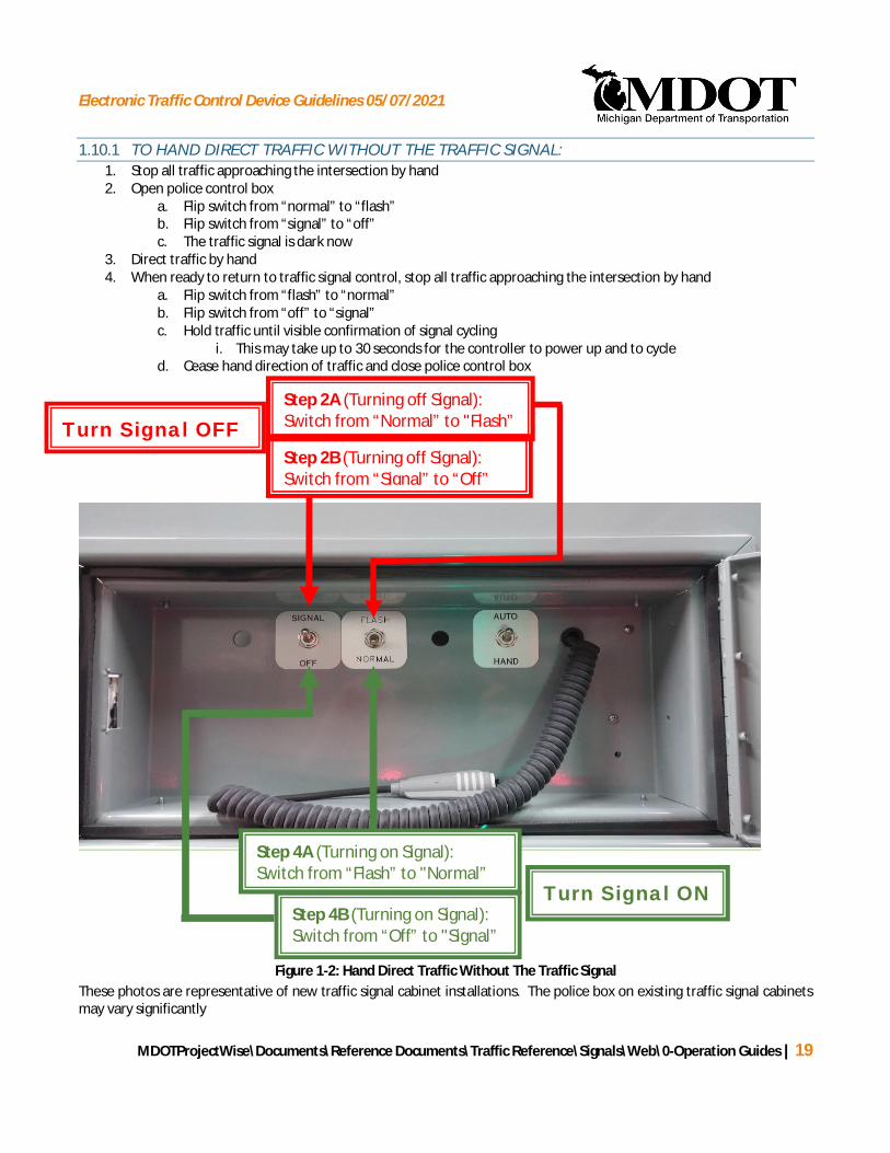
Electronic Traffic Control Device Guidelines 05/07/2021
MDOTProjectWise\Documents\Reference Documents\Traffic Reference\Signals\Web\0-Operation Guides | 19
1.10.1 TO HAND DIRECT TRAFFIC WITHOUT THE TRAFFIC SIGNAL:1. Stop all traffic approaching the intersection by hand2. Open police control box
a. Flip switch from “normal” to “flash”b. Flip switch from “signal” to “off”c. The traffic signal is dark now
3. Direct traffic by hand4. When ready to return to traffic signal control, stop all traffic approaching the intersection by hand
a. Flip switch from “flash” to “normal”b. Flip switch from “off” to “signal”c. Hold traffic until visible confirmation of signal cycling
i. This may take up to 30 seconds for the controller to power up and to cycled. Cease hand direction of traffic and close police control box
Figure 1-2: Hand Direct Traffic Without The Traffic SignalThese photos are representative of new traffic signal cabinet installations. The police box on existing traffic signal cabinetsmay vary significantly
Step 2A (Turning off Signal):Switch from “Normal” to "Flash”
Step 2B (Turning off Signal):Switch from “Signal” to “Off”
Turn Signal OFF
Step 4A (Turning on Signal):Switch from “Flash” to "Normal”
Step 4B (Turning on Signal):Switch from “Off” to "Signal”
Turn Signal ON
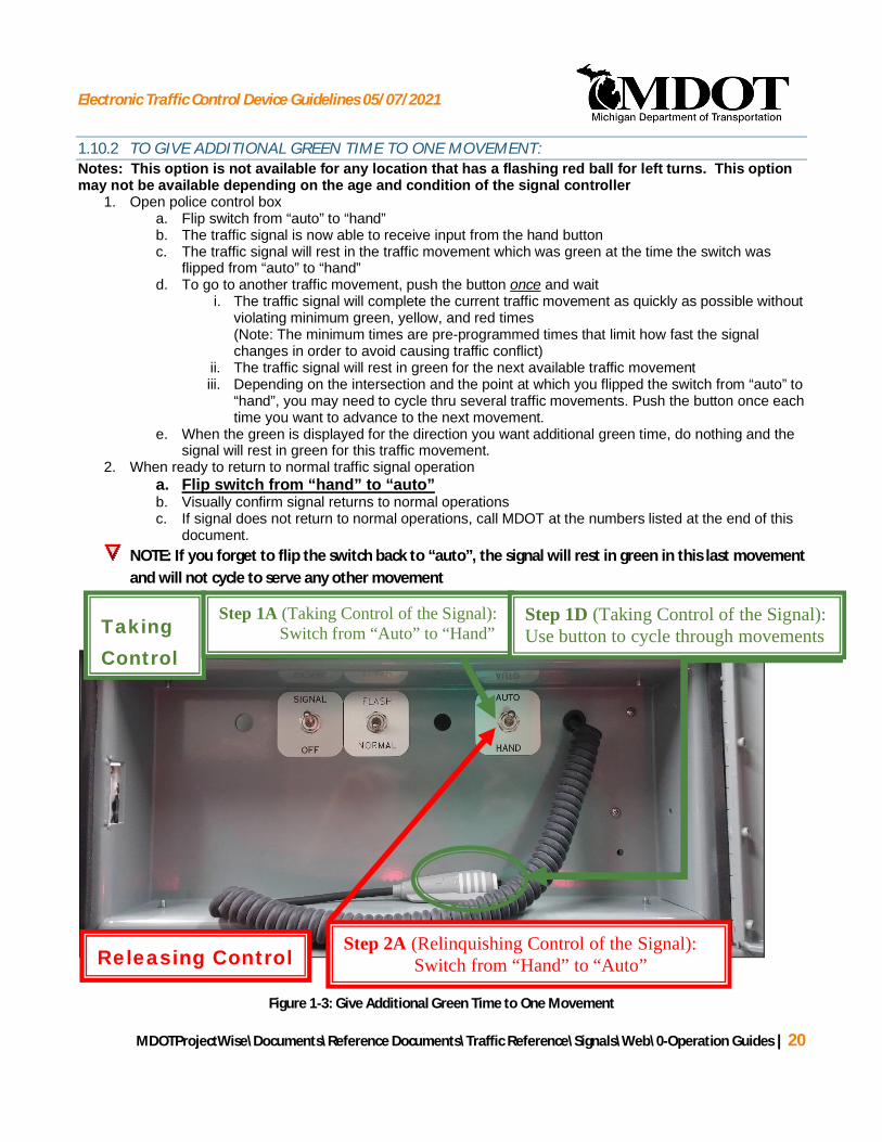
Electronic Traffic Control Device Guidelines 05/07/2021
MDOTProjectWise\Documents\Reference Documents\Traffic Reference\Signals\Web\0-Operation Guides | 20
1.10.2 TO GIVE ADDITIONAL GREEN TIME TO ONE MOVEMENT:Notes: This option is not available for any location that has a flashing red ball for left turns. This optionmay not be available depending on the age and condition of the signal controller
1. Open police control boxa. Flip switch from “auto” to “hand”b. The traffic signal is now able to receive input from the hand buttonc. The traffic signal will rest in the traffic movement which was green at the time the switch was
flipped from “auto” to “hand”d. To go to another traffic movement, push the button once and wait
i. The traffic signal will complete the current traffic movement as quickly as possible withoutviolating minimum green, yellow, and red times(Note: The minimum times are pre-programmed times that limit how fast the signalchanges in order to avoid causing traffic conflict)
ii. The traffic signal will rest in green for the next available traffic movementiii. Depending on the intersection and the point at which you flipped the switch from “auto” to
“hand”, you may need to cycle thru several traffic movements. Push the button once eachtime you want to advance to the next movement.
e. When the green is displayed for the direction you want additional green time, do nothing and thesignal will rest in green for this traffic movement.
2. When ready to return to normal traffic signal operationa. Flip switch from “hand” to “auto”b. Visually confirm signal returns to normal operationsc. If signal does not return to normal operations, call MDOT at the numbers listed at the end of this
document.NOTE: If you forget to flip the switch back to “auto”, the signal will rest in green in this last movementand will not cycle to serve any other movement
Figure 1-3: Give Additional Green Time to One Movement
Releasing ControlStep 2A (Relinquishing Control of the Signal): Switch from “Hand” to “Auto”
TakingControl
Step 1A (Taking Control of the Signal): Switch from “Auto” to “Hand”
Step 1D (Taking Control of the Signal):Use button to cycle through movements

Electronic Traffic Control Device Guidelines 05/07/2021
MDOTProjectWise\Documents\Reference Documents\Traffic Reference\Signals\Web\0-Operation Guides | 21
Figure 1-4: Contact Information for each MDOT Region
Superior Region906-786-1800
North Region989-731-5090 Bay Region
989-754-7443
Metro Region248-483-5100
University Region517-750-0401
Southwest Region269-337-3900
Grand Region616-451-8329
Electronic Traffic Control Device Guidelines 05/07/2021
MDOTProjectWise\Documents\Reference Documents\Traffic Reference\Signals\Web\0-Operation Guides | 22
1.11 TEMPORARY TRAFFIC SIGNALS
Temporary traffic signals are often requested as part of construction projects. They can generally be brokendown into two types: Signals at crossroads and signals to alternate traffic in a single lane.
1.11.1 TEMPORARY TRAFFIC SIGNALS AT CROSSROADS
Traffic patterns cause by construction closures will sometimes create the need for a temporary traffic signal atan intersection. It is still necessary that a warrant be met if a signal is installed and the signal request must bereviewed and approved by the MDOT Signals Unit. Because the determination to install a temporary signal mustbe made prior to the start of construction, estimated volumes and delays must be used in the analysis.
While design should include initial signal timings, due to the variability in construction volumes, it is oftendesirable to make provisions to review the operations and update the timings during construction to account foractual traffic volumes.
Particular attention should be given to the temporary nature of the traffic signal. Once installed, there is oftenconsiderable resistance to the removal of the temporary traffic signal by the local community. Unless there isintent to leave the signal as a permanent installation, there should be clear written confirmation from the localgovernmental agencies that they understand and agree that the temporary traffic signal will be removed at theend of the project.
1.11.2 TEMPORARY TRAFFIC SIGNALS TO ALTERNATE TRAFFIC IN A SINGLE LANE (FORMERLY T&SNOTE 906A)
Temporary traffic signals and street lighting become necessary on bridge deck repair or improvement projectswhen only one lane of traffic can be maintained at a time on a two way roadway. The Signals Unit maintainstypical installation plans for such work.
No roads or driveways may be between the temporary signal heads. In the event a side road or driveway iswithin 200 feet (60 meters) of the stop bar, a custom signal design will be required or a detour should beconsidered. The busier the side road, the greater the distance should be between the stop bar and the sideroad. Contact the MDOT Signals Unit on any projects requiring temporary traffic signals.
Temporary portable traffic signals are only for use on projects with a short duration. The MDOT Signals Unitdoes not typically provide timing permits for temporary portable traffic signals. The following all red intervals(per direction) are based on assumed speeds of 25 MPH as a function of distance between stop bars.

Electronic Traffic Control Device Guidelines 05/07/2021
MDOTProjectWise\Documents\Reference Documents\Traffic Reference\Signals\Web\0-Operation Guides | 23
All-Red Intervals for Temporary Traffic Signals
Assumptions:
§ A 25 MPH speed limit through work zone.
§ Distances should be rounded up to the nearest 50 feet.
§ Typically stop bars are 50 feet from the signal heads.
§ Green time should be adjusted to match traffic demand.
§ Yellow interval should be 5.0 seconds.
1.12 REMOVAL OF EXISTING TRAFFIC SIGNALS
Traffic control devices are used at intersections to regulate the flow of conflicting traffic streams. Over time,traffic patterns and land uses can change and a signal at a particular intersection may no longer be justified.
Distance Between Stop BarsFeet (meters)
All Red IntervalSeconds (per Direction)
200 (60) 5250 (75) 7300 (90) 8350 (105) 10400 (120) 11450 (135) 12500 (150) 14550 (165) 15600 (180) 16650 (200) 18700 (215) 19750 (230) 20800 (245) 22850 (260) 23900 (275) 25950 (290) 261000 (305) 271050 (320) 291100 (335) 301150 (350) 311200 (365) 33
Electronic Traffic Control Device Guidelines 05/07/2021
MDOTProjectWise\Documents\Reference Documents\Traffic Reference\Signals\Web\0-Operation Guides | 24
Federal funding cannot be used to modernize an unwarranted signal. Prior to modernizing a signal, warrantsmust be verified. If a signal appears to be unwarranted, a thorough review is required to determine if the signalis warranted. If warranted, modernization can proceed. If unwarranted, coordination with any affected localagency is required to establish an appropriate course of action.
MDOT’s guidance document 10200 titled “GUIDELINES FOR REVIEWING TRAFFIC SIGNALS FOR POTENTIALREMOVAL”provides a step-by-step process used to analyze existing signalized intersections to determine if atraffic signal is warranted and to assist the Region/Transportation Service Center (TSC) in interacting with localagencies where traffic signal removal may be indicated. This process only applies to intersections wheresignalization is already in place and should not be used for installation of a new signal.

Electronic Traffic Control Device Guidelines 05/07/2021
MDOTProjectWise\Documents\Reference Documents\Traffic Reference\Signals\Web\0-Operation Guides | 25
2 LEFT-TURN PHASING GUIDELINES
This chapter documents the different types of left-turn phasing used in the State of Michigan and providesguidance for determining when to consider the use of left-turn phasing as well as which type of left-turn phasingwould be appropriate. Additional guidance is provided on when to consider the removal of left-turn phasing.
MDOT has an online spreadsheet LEFT TURN PHASING.XLS to perform left-turn phasing threshold analysis.Instructions can be found in a tab of the online spreadsheet.
2.1 TYPES OF LEFT-TURN PHASING
There are three types of left-turn phasing currently in use in the State of Michigan:
1. Permissive-Protected (lagging) left-turn phasing is when the left-turn movement is permissive during aportion of the cycle length (must yield to opposing traffic) and protected during a portion of the cyclelength (exclusive signal phase).
2. Protected-Permissive (leading) left-turn phasing is when the left-turn movement is protected during aportion of the cycle length (exclusive signal phase) and permissive during a portion of the cycle length(must yield to opposing traffic).
3. Protected-Only left-turn phasing is when the left-turn movement can only be made during an exclusiveleft-turn phase.
In some situations, it may be advantageous to corridor progression for the left-turn phase to lead the adjacentthrough movement and the opposite phase will lag the adjacent thru movement (often referred to as Lead/Lagphasing).
§ Note: Opposing left-turn phases generally should match left-turn phasing type for consistent driverexpectations.
The signal head displays used during the permissive operation are the flashing yellow arrow (in a four- sectionhead) or the green ball (in a four or five-section head). The flashing red ball in a three-section left-turn signalhead is being phased out. The display used for the Protected-Only operation is a steady green arrow.
2.2 WHEN TO CONSIDER LEFT-TURN PHASING
While left-turn phasing generally will improve the capacity and level of service for the left-turn traffic, ittypically, reduces the overall intersection capacity and level of service. Left-turn phasing should only beconsidered where the benefits outweigh the costs. Left-turn phasing should be considered at signalizedintersections when the thresholds below are met:

Electronic Traffic Control Device Guidelines 05/07/2021
MDOTProjectWise\Documents\Reference Documents\Traffic Reference\Signals\Web\0-Operation Guides | 26
§ The left-turn peak hour volume exceeds 90 vehicles per hour (VPH)1, and
§ The product of opposing through hourly volume (VHP) and left-turn hourly volumes (VHP) exceeds50,000 (if there is one opposing through2 lane) or 100,000 (if there are two or more opposing through2
lanes), or
§ A crash pattern that could be corrected with left-turn phasing is evident, or
§ Left-turn delay is greater than or equal to 2.0 vehicle-hours AND greater than 35 seconds per vehicleduring a peak hour.
Meeting the thresholds should not be considered a requirement to install left-turn phasing. Left-turn phasingshould only be approved and installed after a comprehensive engineering study indicates this is necessary forthe safe and efficient operation of an intersection. The type of left-turn phasing will be determined based ondata from the engineering study which includes the amount of delay experienced by left-turning traffic, crashpatterns that may be occurring and available capacity of the intersection.
2.3 DETERMINING LEFT-TURN PHASING TYPE
After a comprehensive engineering study indicates left-turn phasing is necessary for the safe and efficientoperation of an intersection, it must be determined whether the left-turn phase will be “Protected-only” or ifthere will also be a permissive portion of the left-turn phase (typically Permissive-Protected). Generally, anincremental approach is preferred with Permissive-Protected (or Protected-Permissive) left-turn phasing beingutilized before moving to Protected-Only left-turn phasing. Including a permissive portion in the left turn phasetypically results in higher capacity and a better level of service for the left-turn movement(s) and for the overallintersection. The following guidelines are to be considered for the determination of the left-turn phasing type.
2.3.1 PERMISSIVE-PROTECTED AND PROTECTED-PERMISSIVE LEFT-TURN PHASING
Permissive-Protected and Protected-Permissive left-turn phasing may be considered under the followingconditions:
§ Adequate sight distance for left-turning vehicles and opposing through traffic is available or can bemade available by implementing geometric or pavement marking improvements.
1 A 90 vehicle/hour threshold is based on typical cycle length in which 2 veh/cycle can clear during the phase change. If the traffic signal being evaluatedhas a higher cycle length then engineering judgment should be provided on consideration of a lower threshold.
2 Through lanes include combination lanes such as through/right turn or through/left-turn. Exclusive turn lanes are NOT counted in this opposingcalculation.

Electronic Traffic Control Device Guidelines 05/07/2021
MDOTProjectWise\Documents\Reference Documents\Traffic Reference\Signals\Web\0-Operation Guides | 27
§ There are no more than three (3) lanes of opposing through traffic (including shared through lanes).
§ Intersection geometrics do not promote hazardous conditions.
§ A crash pattern is evident which could be corrected with left-turn phasing. A crash pattern3 exists if:
Ø By approach, there are four (4) correctable left-turn crashes in one consecutive 12 month periodOR six (6) correctable crashes in a 24 month period.
Ø For a pair of conflicting approaches, there are six (6) correctable crashes in one consecutive 12month period OR nine (9) correctable crashes in a 24 month period.
When these crash thresholds are met, additional accident analysis should be conducted todetermine if there are any causes, such as insufficient sight distance, that could be mitigated toeliminate the need for left-turn phasing.
2.3.2 PROTECTED-ONLY LEFT-TURN PHASING
Protected-Only left-turn phasing may be considered under the following conditions:
§ Sight distance to opposing traffic is inadequate due to geometry or opposing left-turn vehicles andwhere offsetting the left-turn lanes is not feasible or will not provide the required minimum sightdistance.
Ø MDOT’S online “SIGHT DISTANCE GUIDELINES” provide details for the determination andmeasurement of intersection sight distance.
§ Left-turn traffic must cross four or more lanes of opposing through traffic2.
§ There are dual left-turn lanes on the approach. (Permissive-Protected and Protected-Permissive left-turnphasing should not be used with dual turn lanes)
§ Left-turn phasing is existing and a correctable crash pattern exists. A crash pattern3 exists if:
3 Left-Turn Phasing Thresholds are based on the following documents:
Traffic Signal Timing Manual, USDOT, Federal Highway Administration Publication Number: FHWA-HOP-08-024, June 2008: Pg 4-13; Figure 4-11: “Guidelines for determining the potential need for a left-turn phase”
“Guidelines for the Installation of Left-Turn Phasing”, Research Report KTC-95-23, K.R. Agent, Nikiforos Stamatiadis, and Bryan Dye, December,1995
Electronic Traffic Control Device Guidelines 05/07/2021
MDOTProjectWise\Documents\Reference Documents\Traffic Reference\Signals\Web\0-Operation Guides | 28
Ø By approach, there are four (4) correctable left-turn crashes in a 12 month period OR six (6)correctable left-turn crashes in a 24 month period.
Ø For a pair of conflicting approaches, there are six (6) correctable left-turn crashes in a 12 monthperiod OR nine (9) correctable left-turn crashes in a 24 month period.
§ No previous left-turn phasing exists and when one the following correctable crash patterns3 exist:
Ø By approach, there are six (6) correctable crashes in one consecutive 12 month period OReleven (11) correctable crashes in a 24 month period.
Ø For a pair of conflicting approaches, there are eleven (11) correctable crashes in oneconsecutive 12 month period OR eighteen (18) correctable crashes in a 24 month period.
When these crash thresholds are met, additional accident analysis should be conducted to determine ifthere are any causes, such as insufficient sight distance, that could be mitigated to eliminate the needfor left-turn phasing.
§ The posted speed limit of opposing traffic is greater than 45 mph.
§ The product of left-turn and opposing through traffic hourly volumes (VPH) exceeds 150,000 for oneopposing lane or 300,000 for two or more opposing lanes. The number of hours the cross productmeets thresholds should also be considered in determining protected phasing.
2.4 REMOVAL OF EXISTING LEFT-TURN SIGNAL PHASING
Removal of left-turn phasing or changing from a Protected-Only left-turn phasing to Permissive/Protected orProtected/Permissive left-turn phasing requires the completion of an engineering study. The engineering studyshould consider the following:
§ Crash history prior to the installation of the protected left-turn phasing. If the signal was installed dueto left-turn crashes, Protected-Only phasing should be maintained unless the engineering studyindicates a reduction in potential vehicle conflicts.
§ The recent crash history to determine if there is evidence that a reduction in rear-end crashes may beachieved.
§ Evaluation to ensure adequate sight distance for left-turning drivers
§ Evaluation of the overall impact to intersection operations if the phasing change were implementedincluding an estimate of the expected reduction in delay per vehicle entering the intersection and theanticipated benefit from left-turn lane queue reduction.

Electronic Traffic Control Device Guidelines 05/07/2021
MDOTProjectWise\Documents\Reference Documents\Traffic Reference\Signals\Web\0-Operation Guides | 29
§ Additional factors such as high pedestrian volumes, traffic signal progression, geometric design,maneuverability of particular classes of vehicles, adequacy of gaps, or operational requirements uniqueto pre-emption systems.
§ Follow up crash evaluation after the implementation of the less restrictive form of left-turn phasing, todetermine if a correctable crash pattern develops. If a correctable crash pattern does develop, then theprior left-turn phasing should be reinstalled.
Electronic Traffic Control Device Guidelines 05/07/2021
MDOTProjectWise\Documents\Reference Documents\Traffic Reference\Signals\Web\0-Operation Guides | 30
3 PEDESTRIAN SIGNAL GUIDELINES
This chapter details the requirements associated with the use of pedestrian traffic signal indications. Whilepedestrians can generally observe the vehicular traffic signals to determine when it is safe to cross, separatepedestrian signal indications provide direction that is clearer and aids pedestrians in determining if there issufficient time remaining in the phase to safely cross the roadway.
In addition, with the utilization of more complex signal phasing and adaptive signal operations, it may not beclear to pedestrians when conflicting traffic streams will be stopped even if they are familiar with theoperations. Pedestrian traffic signal indications reduce the potential for confusion.
3.1 WHEN TO INSTALL PEDESTRIAN SIGNAL INDICATIONS
Pedestrian signal indications are installed at locations where pedestrian activity is clearly evident. Evidence mayinclude the following:
§ Sidewalks crossing the intersection.
§ Well-worn paths near the intersection.
§ Counts indicating pedestrian activity
§ Proposed projects involving new sidewalks or non-motorized path crossings should include any signalrelated work required to accommodate pedestrians and path users.
Depending on the equipment, the addition of pedestrian facilities to an existing traffic signal may requirecomplete modernization of the signal. Unless there is a safety or operational concern, pedestrian signalindications will typically not be able to be added to an existing signalized location until it can be modernized.
There may be situations in which it is desirable to prohibit pedestrians from crossing certain legs of anintersection. For example: at an intersection with dual left turns and split phase signal operations, it isundesirable to allow pedestrians to cross the path of the protected, left turning vehicular movement.
Furthermore, the GUIDANCE FOR INSTALLATION OF PEDESTRIAN CROSSWALKS ON MICHIGAN STATETRUNKLINE HIGHWAYS is available as a reference. This guidance document provides a step-by-step procedureto identify the appropriate location for a crosswalk and selection of appropriate crossing treatments on statetrunklines. Where the installation of Pedestrian Hybrid Beacon, Pedestrian Signals, or Rectangular RapidFlashing Beacon Signs are deemed appropriate, a request for a study of an electronic pedestrian device issubmitted to MDOT Signal Operations by using the SIGNAL STUDY SCREENING FORM (1597).
Electronic Traffic Control Device Guidelines 05/07/2021
MDOTProjectWise\Documents\Reference Documents\Traffic Reference\Signals\Web\0-Operation Guides | 31
3.2 HOW TO OPERATE PEDESTRIAN SIGNALS
The timing of pedestrian signals is described in Chapter 4, including the meaning of the indications, when theyshould be displayed, and how to calculate the time intervals.
Pedestrian signals are typically operated in one of two ways:
§ The pedestrian signals provide a walk interval every signal timing cycle
§ The pedestrian signals only provide a walk interval if a pushbutton is activated
Pushbuttons should be located so they are clearly visible to pedestrians approaching the intersection, andshould be signed so it is clear which crossing the pushbutton is associated with. The pushbuttons should belocated adjacent to the sidewalk and accessible to disabled persons in accordance with the MMUTCD andMDOT’s online PUSHBUTTON DESIGN details and construction PEDESTRIAN PUSHBUTTON DETAILS .
3.3 COUNTDOWN PEDESTRIAN SIGNALS
Pedestrian countdown displays are mandatory for new installations. These devices inform pedestrians of thenumber of seconds remaining to safely complete their crossing. The display of the number of remaining secondsis concurrent with the flashing UPRAISED HAND indication and counts down to zero at the end of the flashingUPRAISED HAND. After the countdown displays zero the number part of the indication goes dark and a steadyUPRAISED HAND is displayed.
3.4 ACCESSIBLE PEDESTRIAN SIGNALS
Accessible pedestrian signals and detectors provide information in non-visual formats (such as audible tones,speech messages, and/or vibrating surfaces). These devices provide additional information to visually impairedindividuals. MDOT will install them in specific situations. The Michigan Manual of Uniform Traffic ControlDevices (MMUTCD) gives the following guidance:
If a particular signalized location presents difficulties for pedestrians who have visual disabilities to cross theroadway, an engineering study should be conducted that considers the needs of pedestrians in general, as wellas the information needs of pedestrians with visual disabilities. The engineering study should consider thefollowing factors:
§ Potential demand for accessible pedestrian signals;
§ A request for accessible pedestrian signals;
§ Traffic volumes during times when pedestrians might be present, including periods of low trafficvolumes or high turn-on-red volumes;

Electronic Traffic Control Device Guidelines 05/07/2021
MDOTProjectWise\Documents\Reference Documents\Traffic Reference\Signals\Web\0-Operation Guides | 32
§ The complexity of traffic signal phasing (such as split phases, protected turn phases, leading pedestrianintervals, and exclusive pedestrian phases); and
§ The complexity of intersection geometry.
For MDOT to consider the use of accessible pedestrian signals, the location must first meet the following basiccriteria:
§ The intersection must already be signalized.
§ The local governmental agency must submit a written request to MDOT including the following:
Ø Confirmation that the local agency has worked with any landowners that may be affected by theaudible features, and they have concluded that the location is suitable in terms of noise leveland neighborhood acceptance.
Ø If required due to the complexity of an intersection or if these devices are new to themunicipality, confirmation should be provided that a mobility specialist has concurred that thelocation is suitable in terms of safety.
Ø A demonstrated need typically documented by user request
If the above criteria are met, MDOT will conduct an engineering study in accordance with the MMUTCD todetermine if the use of accessible pedestrian signals is appropriate.
Accessible pedestrian signals will not typically be mixed with non-accessible pedestrian signals at the samesignalized intersection.
To provide optimal operation of accessible pedestrian signals, the devices will cycle only when a pushbutton isactivated.

Electronic Traffic Control Device Guidelines 05/07/2021
MDOTProjectWise\Documents\Reference Documents\Traffic Reference\Signals\Web\0-Operation Guides | 33
4 SIGNAL TIMING CALCULATIONS
This chapter provides guidance on the calculation of vehicle change and clearance intervals, pedestrianclearance intervals, and minimum splits. MDOT has a standard online spreadsheet (Y & R & PED TIMING.XLS)that should be used to determine these intervals.
The timing of traffic signals requires the consideration of a number of interrelated variables. These are used asthe basis for setting the overall framework for timings at traffic signals. A Yellow change interval and an All-Redclearance interval are provided for vehicular phases. The Yellow Change interval includes perception reactiontime and the time it takes to decelerate the vehicle to a stop. The All-Red clearance interval is the time it takes avehicle to completely clear the intersection at the approach speed.
Walk, Flashing Don’t Walk (FDW), and Steady Don’t Walk Buffer Intervals are provided for pedestrian crossings.The Walk interval is intended to give the pedestrian sufficient time to travel from the pedestrian detector (orfrom behind the curb if there is no pedestrian detector) to a point just beyond the near face of curb to begintheir crossing. The FDW interval (combined with the buffer interval) is intended to provide the pedestrian withthe time necessary to walk from the near curb (or shoulder) to the far side of the traveled way (or to a medianof sufficient width for pedestrians to wait). The Steady Don’t Walk Buffer Interval (BI) provides a buffer betweenthe end of the FDW interval and the release of conflicting traffic.
Clearance intervals for both vehicles and pedestrians must provide sufficient notice to either avoid entering anintersection if there is insufficient time or to clear the intersection safely. In addition to clearance intervals, if aGreen or Walk interval is too short, drivers or pedestrians may miss their opportunity or out of frustration maychoose to enter when there is insufficient time to clear the intersection safely. Where vehicle and pedestriandetection systems are available, the traffic signal controller must be programmed properly to avoid wasting timeunnecessarily while still servicing all traffic as efficiently as possible.
4.1 VEHICULAR CLEARANCE INTERVAL CALCULATIONS
When calculating change and clearance intervals, opposing directions (northbound and southbound forexample) of traffic should be calculated separately, and the larger of the calculated Yellow and All-Red valuesshould be applied to both paired approaches. However, if opposing directions of traffic are operating as splitphased, they should be calculated independent of each other. The Yellow and All-Red times calculated for thethrough movements of an approach are typically also used for any adjacent left turn phasing unless engineeringjudgment indicates otherwise.
4.1.1 YELLOW CHANGE INTERVALS
Calculation of Yellow change intervals shall adhere to the following methodology:

Electronic Traffic Control Device Guidelines 05/07/2021
MDOTProjectWise\Documents\Reference Documents\Traffic Reference\Signals\Web\0-Operation Guides | 34
= +2( + 32.2 )
Where: Y = Yellow change interval (seconds)t = Driver perception-reaction time for stopping (seconds)v = Approach speed (feet/second)a = Deceleration rate for stopping (feet/sec2)G = Grade of approach, with uphill positive and downhill negative (percent grade/100)
t = 1.0 seconda = 10 feet/sec2
v = Measured 85th percentile speed is preferred, but if not available use posted speed (for driveways/malls, freeway ramps and crossovers use 25 mph)
§ The following formula shall be used to calculate the Yellow interval:
Use the following predetermined values in the above formula when calculating the Yellow change interval:
§ The range of the Yellow interval shall be between 3.0 seconds to a maximum value calculated by theformula above. Calculated intervals less than 3.0 seconds shall be increased to 3.0 seconds.
§ If the calculated value exceeds 6.0 seconds, confirm with the MDOT Signals Unit prior to use.
§ Yellow intervals shall be rounded to the nearest 1/10th of a second.
§ The grade of the roadway should be estimated or measured. 0% should generally be used unless thegrade is estimated to be greater than 2%. If a grade other than 0% is used, it should be noted in theremarks section of the timing permit.
4.1.2 ALL-RED CLEARANCE INTERVALS
Calculation of All-Red clearance intervals shall adhere to the following methodology:
§ The following formula shall be used to calculate the All-Red clearance interval:

Electronic Traffic Control Device Guidelines 05/07/2021
MDOTProjectWise\Documents\Reference Documents\Traffic Reference\Signals\Web\0-Operation Guides | 35
=+v
Where: AR = All-Red interval (seconds)w = Width of intersection, measured from the near-side stop bar to the far edge of
the conflicting extended travel lane along the actual vehicle path of a throughvehicle (feet). The measurement should include any right turn lanes as conflictinglanes of traffic. At “T” intersections, “w” is measured from the near-side stop barto the opposing curb in the path a through vehicle would travel. Figure 4-1illustrates how “w” is measured for both a standard 4-leg intersection and a “T”intersection. The intersection width should be rounded up to the nearest 5-footincrement
L = Length of vehicle (feet)v = Approach speed (feet/second)
L = 20 feetv = Measured 85th percentile speed is preferred, but if not available use posted speed unless site
conditions indicate otherwise. For T intersections use 20 Mph for the traffic approaching theintersection along the stem of the T (the traffic that must turn). For private driveways orlocal streets with no posted speed, use 25 Mph unless site conditions indicate otherwise.
Use the following predetermined values in the above formula when calculating the All-Red interval:
§ The All-Red interval cannot be less than 1 second or greater than the calculated value using the formulaabove.
§ If the calculated value exceeds 4.0 seconds, confirm with the MDOT Signals Unit prior to use.
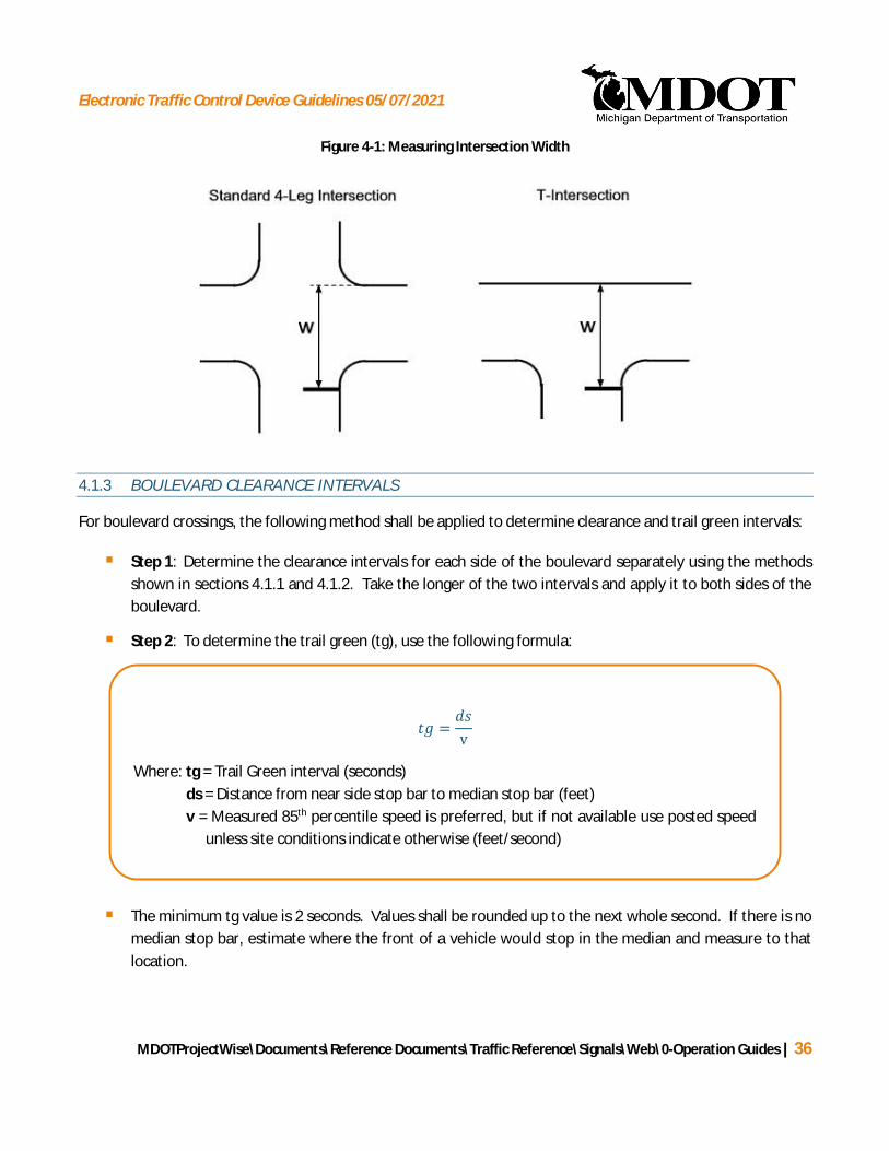
Electronic Traffic Control Device Guidelines 05/07/2021
MDOTProjectWise\Documents\Reference Documents\Traffic Reference\Signals\Web\0-Operation Guides | 36
=v
Where: tg = Trail Green interval (seconds)ds = Distance from near side stop bar to median stop bar (feet)v = Measured 85th percentile speed is preferred, but if not available use posted speed
unless site conditions indicate otherwise (feet/second)
Figure 4-1: Measuring Intersection Width
4.1.3 BOULEVARD CLEARANCE INTERVALS
For boulevard crossings, the following method shall be applied to determine clearance and trail green intervals:
§ Step 1: Determine the clearance intervals for each side of the boulevard separately using the methodsshown in sections 4.1.1 and 4.1.2. Take the longer of the two intervals and apply it to both sides of theboulevard.
§ Step 2: To determine the trail green (tg), use the following formula:
§ The minimum tg value is 2 seconds. Values shall be rounded up to the next whole second. If there is nomedian stop bar, estimate where the front of a vehicle would stop in the median and measure to thatlocation.

Electronic Traffic Control Device Guidelines 05/07/2021
MDOTProjectWise\Documents\Reference Documents\Traffic Reference\Signals\Web\0-Operation Guides | 37
=v
Where: CPCT = Calculated Pedestrian Clearance Time (seconds)d = Distance from curb to curb (feet)v = Walking speed of 3.5 feet/second
4.2 PEDESTRIAN CLEARANCE INTERVAL CALCULATIONS
4.2.1 WALK INTERVALS
For locations with pedestrian signals, the pedestrian walk interval should generally be 7.0 seconds or greater.Walk intervals less than 7.0 seconds will be considered if the pedestrian time requirements exceed the vehiculartime requirements for that particular movement, and if pedestrian volumes, characteristics, and pedestriandetector locations do not require a 7.0 second walk interval. The walk interval shall be no less than 4.0 seconds.
The walk interval may need to be more than 7.0 seconds based on the location of pedestrian detectors and thelength of the crossing: The sum of the walk interval plus the FDW interval plus the buffer interval should besufficient to allow a pedestrian to travel from the pedestrian detector (if no pedestrian detector then use 6’behind curb) to the far curb at a speed of 3.0 feet per second. Any additional time that is required to satisfy theconditions of this paragraph should be added to the walk interval. The online spreadsheet (Y & R & PEDTIMING.XLS) accounts for this and will increase the minimum walk interval accordingly. It is best to start with aminimum walk interval assumption of 4.0 seconds in the spreadsheet so it is apparent if this calculation iscontrolling the minimum walk time.
4.2.2 PEDESTRIAN CLEARANCE TIME
The 2011 MMUTCD requires a clear distinction between the pedestrian clearance time and the FDW interval.The calculated pedestrian clearance time (CPCT) is the time calculated for a pedestrian to walk (assumedwalking speed of 3.5 feet per second) from the near curb (or shoulder) to the far side of the traveled way (or toa median of sufficient width for pedestrians to wait).
The CPCT is calculated as follows:
§ If a crosswalk exists, distance is measured along the center of the crosswalk. If the crosswalk is on aradius and is significantly impacting the CPCT, the MDOT Signals Unit may authorize a measurementalong the crosswalk line closest to the stop bar from near curb to far curb. (see Figure 4-2 scenario A).

Electronic Traffic Control Device Guidelines 05/07/2021
MDOTProjectWise\Documents\Reference Documents\Traffic Reference\Signals\Web\0-Operation Guides | 38
§ If there are two concurrent crosswalks, then use the longer crosswalk distance (see Figure 4-2 scenarioB).
§ If there is a median refuge that is clearly designed and designated for pedestrians to wait to cross in twostages, then use the longer crosswalk distance (see Figure 4-2 scenario C)
§ If there is a median that is NOT clearly designed and designated as a refuge for pedestrians to wait tocross in two stages, then use the complete crossing distance similar to Figure 4-2 scenario A or B)
§ If there is no crosswalk and/or no stop bar, measure the distance from near curb to edge of furthesttravel lane extended (see Figure 4-2 scenario D)..
§ If there are no pedestrian features at an intersection (such as marked crosswalks and pedestrian signals)a FDW interval is not required
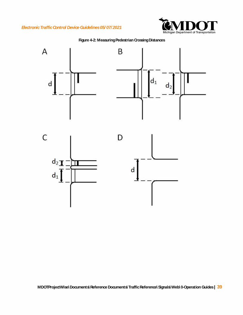
Electronic Traffic Control Device Guidelines 05/07/2021
MDOTProjectWise\Documents\Reference Documents\Traffic Reference\Signals\Web\0-Operation Guides | 39
Figure 4-2: Measuring Pedestrian Crossing Distances
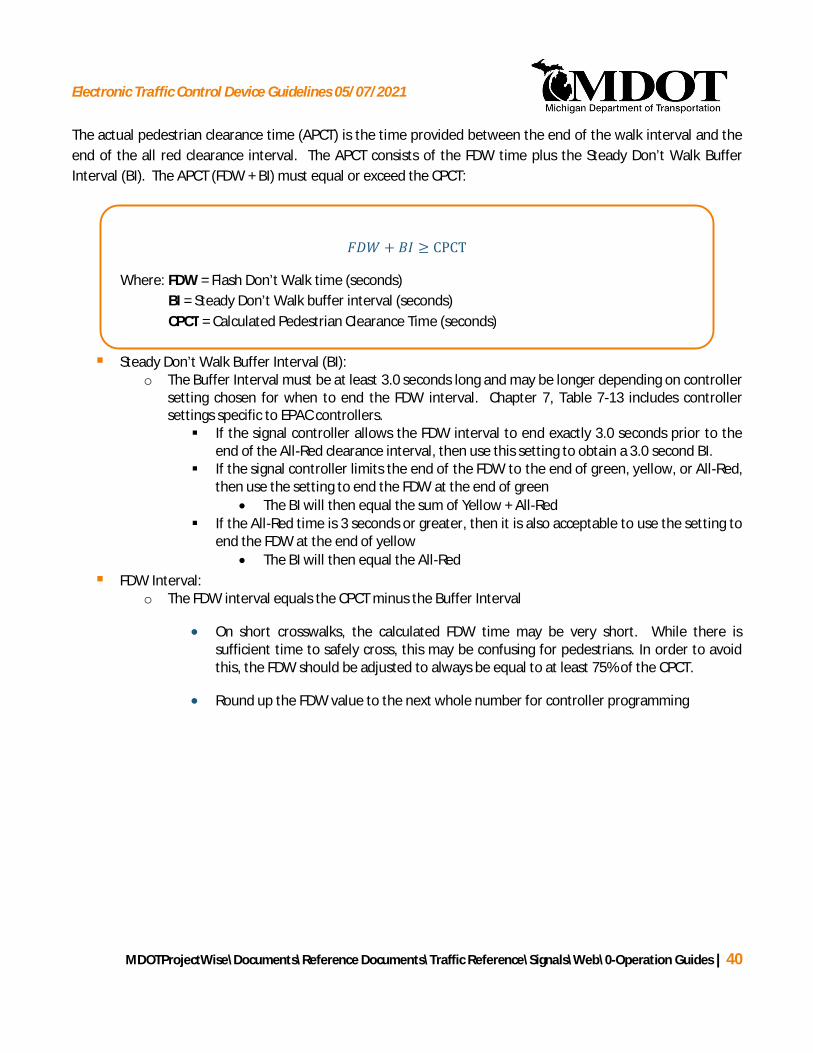
Electronic Traffic Control Device Guidelines 05/07/2021
MDOTProjectWise\Documents\Reference Documents\Traffic Reference\Signals\Web\0-Operation Guides | 40
+ ≥ CPCT
Where: FDW = Flash Don’t Walk time (seconds)BI = Steady Don’t Walk buffer interval (seconds)CPCT = Calculated Pedestrian Clearance Time (seconds)
The actual pedestrian clearance time (APCT) is the time provided between the end of the walk interval and theend of the all red clearance interval. The APCT consists of the FDW time plus the Steady Don’t Walk BufferInterval (BI). The APCT (FDW + BI) must equal or exceed the CPCT:
§ Steady Don’t Walk Buffer Interval (BI):o The Buffer Interval must be at least 3.0 seconds long and may be longer depending on controller
setting chosen for when to end the FDW interval. Chapter 7, Table 7-13 includes controllersettings specific to EPAC controllers.§ If the signal controller allows the FDW interval to end exactly 3.0 seconds prior to the
end of the All-Red clearance interval, then use this setting to obtain a 3.0 second BI.§ If the signal controller limits the end of the FDW to the end of green, yellow, or All-Red,
then use the setting to end the FDW at the end of green· The BI will then equal the sum of Yellow + All-Red
§ If the All-Red time is 3 seconds or greater, then it is also acceptable to use the setting toend the FDW at the end of yellow
· The BI will then equal the All-Red§ FDW Interval:
o The FDW interval equals the CPCT minus the Buffer Interval
· On short crosswalks, the calculated FDW time may be very short. While there issufficient time to safely cross, this may be confusing for pedestrians. In order to avoidthis, the FDW should be adjusted to always be equal to at least 75% of the CPCT.
· Round up the FDW value to the next whole number for controller programming
Electronic Traffic Control Device Guidelines 05/07/2021
MDOTProjectWise\Documents\Reference Documents\Traffic Reference\Signals\Web\0-Operation Guides | 41
4.3 MINIMUM SPLITS
4.3.1 MINIMUM GREEN INTERVALS
Minimum green (minimum initial) intervals are provided to ensure drivers do not miss their green phase andmore importantly, if they are approaching at speed, they are not taken by surprise when a signal turns to greenand then almost immediately turns to Yellow. Minimum green intervals should be determined for each signalphase for the purposes of calculating a minimum split. This applies to both fixed time signals, as well as for anyactuated or semi-actuated signals. Minimum green intervals should be applied as follows:
§ 10.0 seconds should be used for all major street through movements, including:
Ø State trunklines
Ø Major arterial roadways
§ 7.0 seconds should be used for the following:
Ø Minor cross-street movements (i.e. subdivision entrances, driveways, secondary roadways)
Ø All left-turn phasing with the exception of actuated permitted-protected left-turn phasing
Ø At locations with low turning volumes, the minimum green for left-turn phases may be reduced to5.0 seconds with approval of the MDOT project manager.
§ 5.0 seconds should be used for actuated permitted-protected left-turn phasing. A minimum vehiclerecall should always be set for actuated permitted-protected left-turn phasing where a flashing red isused. Locations with a 5 section (dog house) or the flashing Yellow left-turn operation do not requirethe minimum vehicle recall for permitted-protected left-turn phasing
4.3.2 MINIMUM SPLIT CALCULATIONS
The minimum split is the minimum time that must be provided for each vehicular phase or concurrentpedestrian movement to enable vehicles and pedestrians to safely enter and clear the intersection.
The time required to clear pedestrians often exceeds the time allotted for vehicular traffic on the concurrentphase, particularly for side street traffic with concurrent pedestrians crossing the major street. Pushbuttonsshould be considered for this situation. Pushbuttons must be provided for all pedestrian approaches in whichthe concurrent vehicular phase is actuated. Pushbuttons should be considered at intersections that otherwiseoperate fixed time.
If pedestrian signals are provided, but no pushbuttons, then the minimum split must accommodate the requiredpedestrian crossing times.

Electronic Traffic Control Device Guidelines 05/07/2021
MDOTProjectWise\Documents\Reference Documents\Traffic Reference\Signals\Web\0-Operation Guides | 42
( ) = G + Y + AR + 1 second
Where: SPLITmin(vehicle) = Minimum vehicle split (seconds)Gmin = Minimum green interval (seconds)Y = Yellow change interval (seconds)AR = All-Red clearance interval (seconds)
( ) = W + FDW + BI
Where: SPLITmin(pedestrian) = Minimum pedestrian split (seconds)Wmin = Minimum walk interval ( 7 seconds typical)FDW = Flash Don’t Walk time (seconds)BI = Steady Don’t Walk buffer interval (minimum of 3.0 seconds)
If pedestrian signals and pushbuttons are provided, then the minimum split can be based on the vehicularphase, but the pedestrian crossing times must still be calculated and programmed to run upon pushbuttonactivation.
If a pedestrian movement is equipped with pushbuttons, the minimum split based on vehicular movement canbe programmed for the controller to run in the absence of any pushbutton activations, allowing for a shortercycle length. When a pushbutton is activated, it overrides the vehicular phase timing to provide additional timefor pedestrians to cross. If the signal is running in coordination mode, this additional time may cause the signalto be bumped out of coordination for multiple cycle lengths (depending on correction mode and timing).
Depending on the number of pushbutton actuations, especially during peak traffic, the timing plan may need toaccommodate the pedestrian timing within the split and cycle length.
Minimum splits for each phase must be calculated. The minimum vehicle split is calculated with the followingequation:
The minimum pedestrians split is calculated with the following equation:
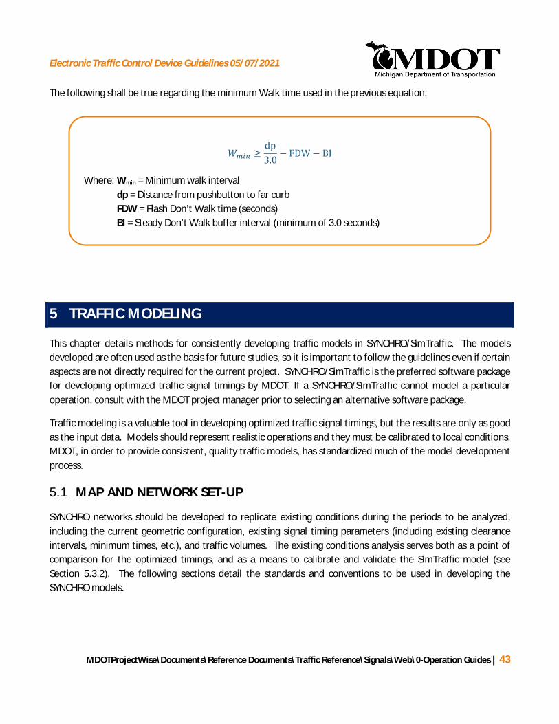
Electronic Traffic Control Device Guidelines 05/07/2021
MDOTProjectWise\Documents\Reference Documents\Traffic Reference\Signals\Web\0-Operation Guides | 43
≥dp3.0
− FDW − BI
Where: Wmin = Minimum walk intervaldp = Distance from pushbutton to far curbFDW = Flash Don’t Walk time (seconds)BI = Steady Don’t Walk buffer interval (minimum of 3.0 seconds)
The following shall be true regarding the minimum Walk time used in the previous equation:
5 TRAFFIC MODELING
This chapter details methods for consistently developing traffic models in SYNCHRO/SimTraffic. The modelsdeveloped are often used as the basis for future studies, so it is important to follow the guidelines even if certainaspects are not directly required for the current project. SYNCHRO/SimTraffic is the preferred software packagefor developing optimized traffic signal timings by MDOT. If a SYNCHRO/SimTraffic cannot model a particularoperation, consult with the MDOT project manager prior to selecting an alternative software package.
Traffic modeling is a valuable tool in developing optimized traffic signal timings, but the results are only as goodas the input data. Models should represent realistic operations and they must be calibrated to local conditions.MDOT, in order to provide consistent, quality traffic models, has standardized much of the model developmentprocess.
5.1 MAP AND NETWORK SET-UP
SYNCHRO networks should be developed to replicate existing conditions during the periods to be analyzed,including the current geometric configuration, existing signal timing parameters (including existing clearanceintervals, minimum times, etc.), and traffic volumes. The existing conditions analysis serves both as a point ofcomparison for the optimized timings, and as a means to calibrate and validate the SimTraffic model (seeSection 5.3.2). The following sections detail the standards and conventions to be used in developing theSYNCHRO models.

Electronic Traffic Control Device Guidelines 05/07/2021
MDOTProjectWise\Documents\Reference Documents\Traffic Reference\Signals\Web\0-Operation Guides | 44
5.1.1 FILE STRUCTURE AND NAMING CONVENTION
SYNCHRO network files should adhere to a standard naming convention unless otherwise discussed in advancewith the MDOT project manager. The following is the standard file naming convention:
Route # - Control Section # - Zone # - Condition – Time Period.syn
The following abbreviations should be used in file naming:
§ Zone Number:
Ø Numeric designation (1, 2, 3…)
Ø “A” for all (the entire control section if no zone breakdown is used, or if multiple zones are includedin the same file)
§ Condition:
Ø “EX” for existing condition
Ø “OPT” for optimized condition
Ø “MIT” for optimized condition with geometric or operational mitigation.
§ Time Period:
Ø “AM” for AM peak period
Ø “PM” for PM peak period
Ø “OP” for mid-day/off-peak period
Ø “NT” for nighttime period (if required due to special circumstances)
Ø “WE” for weekend period (if required due to special circumstances)
Ø “SP-IN” for an inbound special event timing plan
Ø “SP-OUT” for an outbound special event timing plan
Ø “EM-XX” for emergency signal timing plan. XX will indicate the direction of travel as follows:
· NB – Northbound
· SB – Southbound
· EB – Eastbound
· WB – Westbound

Electronic Traffic Control Device Guidelines 05/07/2021
MDOTProjectWise\Documents\Reference Documents\Traffic Reference\Signals\Web\0-Operation Guides | 45
· BI – Bi-directional
Example: The Woodward Avenue (M-1) corridor within the city of Detroit (Control Section 82400) is beingdivided into two zones, or segments, for optimization – Zone 1 and Zone 2. The file being named represents theoptimized condition for Zone 1 during the AM peak period.
File Name = M1-82400-1-OPT-AM.syn
Once a model contains more than one corridor the naming convention may become too large. For isolatedintersections use one SYNCHRO file and place the intersections adjacent to each other but unconnected.Spacing the intersections out geographically causes problems during review as these intersections are easilymissed. If more than one corridor is present use different control section numbers in the file name todifferentiate between models.
File Name = 82300–82400–83500-OPT-AM.syn
5.1.2 MAP SET-UP
A background image of the study area should be inserted in each SYNCHRO model. The background image canbe toggled on/off for ease of loading and navigation. All maps should be imported under the File -> SelectBackgrounds interface. SYNCHRO also allows users to import a background map using Bing maps. Follow theinstructions provided within the software for up-to-date procedures. Once the map is inserted into the file besure that it is scaled properly before beginning to construct the model. If using an imported map, the mapneeds to be scaled to correct proportions manually.
5.1.3 BASIC CODING PARAMETERS
The following procedures and values should be used when coding the basic SYNCHRO network:
LINK NAMING
Link names along a single corridor should be as consistent as possible so that the corridor will be recognized as asingle arterial and be displayed properly in the time-space diagram.
Road names should match the names on the permit. For trunklines, it should start with the route numberfollowed by the local name if there is one.
Dummy nodes should be named alphabetically without duplicates. They should also be consistent betweentime periods.
For intersections utilizing SCATS, the crossroad name should be followed by, “(SCATS)” in order to clarifyoperational questions.

Electronic Traffic Control Device Guidelines 05/07/2021
MDOTProjectWise\Documents\Reference Documents\Traffic Reference\Signals\Web\0-Operation Guides | 46
LINK SPEED
The link speed coded in SYNCHRO provides the basis for evaluating progressive movement between signalizedintersections. Where 85th percentile speeds are available, they should be used. If not available, set the speedsbased on the posted speed limit. A speed limit of 25 MPH should be used for all ramps unless there is a throughmovement, in which case the speed limit should be set to the speed limit (or estimated prevailing speed) of thereceiving lanes. In the event the 85th percentile speeds exceed the posted speed limit, consult with the MDOTproject manager to determine the appropriate speed to use in the models.
IDEAL SATURATED FLOW RATE
The default ideal saturated flow rate for a movement at an intersection should be 2,000 vehicles/hour forprojects in the Metro Region. 1,900 vehicles/hour should be used for all other regions of the State, or asdirected by the MDOT project manager.
VOLUME INPUT
Pedestrian counts and pedestrian push button data should be entered in two different areas. Under the VolumeSettings window, the number of pedestrians counted should be entered under the Conflicting Pedestrians perhour. When inputting pedestrian data into the Phasing Settings window, the data is entered as Pedestrian Callsper hour. It is important to differentiate between the number of pedestrians and the number of actuations/callswhen collecting pedestrian data. Multiple pedestrians may cross under one (1) actuation.
Actual pushbutton actuations per hour can sometimes be determined by reviewing the existing controller’s localalarms report. If not, then review the pedestrian counts in 15 minute time periods and estimate the number ofpushbutton actuations per hour using engineering judgment.
For simplicity, the number of pedestrian calls can be calculated as follows:
§ Up to 5 pedestrians/hour – Pedestrian calls should equal the number of pedestrians.
§ From 5 to 10 pedestrians/hour: 5 calls should be used.
§ For 10 or more pedestrians/hour: Half of the pedestrian volume up to the number of cycles per hour
§ If there are more than 30 pedestrians/hour – Engineering judgment should be used to determine ifthere is a traffic generator such as a school or factory concentrating the pedestrians into a short timeperiod.
To determine which volumes should be entered into the SYNCHRO models, select the Peak Hour for eachintersection and input the corresponding volumes. Once these volumes have been entered, volume balancingbetween the intersections should be completed. Volume balancing can occur through one of two methods.
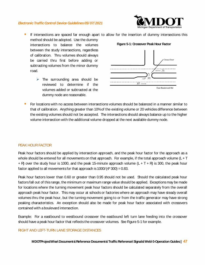
Electronic Traffic Control Device Guidelines 05/07/2021
MDOTProjectWise\Documents\Reference Documents\Traffic Reference\Signals\Web\0-Operation Guides | 47
Figure 5-1: Crossover Peak Hour Factor
§ If intersections are spaced far enough apart to allow for the insertion of dummy intersections thismethod should be adopted. Use the dummyintersections to balance the volumesbetween the study intersections, regardlessof calibration. Thru volumes should alwaysbe carried thru first before adding orsubtracting volumes from the minor dummyroad.
Ø The surrounding area should bereviewed to determine if thevolumes added or subtracted at thedummy node are reasonable.
§ For locations with no access between intersections volumes should be balanced in a manner similar tothat of calibration. Anything greater than 10% of the existing volume or 20 vehicles difference betweenthe existing volumes should not be accepted. The intersections should always balance up to the highervolume intersection with the additional volume dropped at the next available dummy node.
PEAK HOUR FACTOR
Peak hour factors should be applied by intersection approach, and the peak hour factor for the approach as awhole should be entered for all movements on that approach. For example, if the total approach volume (L + T+ R) over the study hour is 1000, and the peak 15-minute approach volume (L + T + R) is 300, the peak hourfactor applied to all movements for that approach is 1000/(4*300) = 0.83.
Peak hour factors lower than 0.60 or greater than 0.95 should not be used. Should the calculated peak hourfactors fall out of this range, the minimum or maximum range value should be applied. Exceptions may be madefor locations where the turning movement peak hour factors should be calculated separately from the overallapproach peak hour factor. This may occur at schools or factories where an approach may have steady overallvolumes thru the peak hour, but the turning movement going to or from the traffic generator may have strongpeaking characteristics. An exception should also be made for peak hour factor associated with crossoverscontained with a boulevard intersection.
Example: For a eastbound to westbound crossover the eastbound left turn lane feeding into the crossovershould have a peak hour factor that reflects the crossover volumes. See Figure 5-1 for example.
RIGHT AND LEFT-TURN LANE STORAGE DISTANCES

Electronic Traffic Control Device Guidelines 05/07/2021
MDOTProjectWise\Documents\Reference Documents\Traffic Reference\Signals\Web\0-Operation Guides | 48
Figure 5-2: Turn Lane Distances
Right and left-turn lane storage lengths should be coded in SYNCHRO as the distance from the stop bar to thebeginning of the taper, or the end of the full-lane width. Figure 5-2 provides an example of the turn lanestorage length to code in SYNCHRO.
For intersections with continuous two-way left-turn lanes, the left-turn lane storage length should typically becoded as 500 feet as a default value. However, care should be taken to consider the impact of opposingdriveways and nearby intersections on the practical storage length available. The following issues should beconsidered in determining storage length in the case of continuous two-way center left-turn lanes:
§ Observed queues exceeding 500 feet contained within the left-turn lane
§ Observed queues of less than 500 feet which overflows from the left-turn lane
§ Closely-spaced driveways or intersections, the location of which reduces the practical available left-turnstorage at the signalized intersection.
Typically, taper lengths should not be measured. However, if an intersection has a long taper length andvehicles are using the taper length as additional storage the portion of the taper being used as storage should bemeasured and coded as part of the storage distance. This should be noted on the inventory sheet.
MINIMUM SPLITS AND CLEARANCE INTERVALS
This section provides an overview of the SYNCHRO inputs for minimum split times and pedestrian and vehicularclearance intervals. For evaluating SYNCHRO outputs, including optimizing signal timings, see Section 5.2.
Minimum split definitions and calculations can be found in Section 4.3.Controller settings determining splits and pedestrian timings can be found inSection 1.1.
§ Yellow and All-Red Time:
These values should be taken directly from MDOT’s onlinespreadsheet Y & R & PED TIMING.XLS noting that Yellow intervalsgreater than 6 seconds and All-Red intervals greater than 4 secondsmust be confirmed with MDOT Lansing Signal Operations.
§ Walk and Flash Don’t Walk Time:
These values should be taken directly from MDOT’s onlinespreadsheet Y & R & PED TIMING.XLS making sure to use thecolumn labeled “FDW Interval-Synchro”. There is also a columnlabeled “FLASH DON’T WALK (CONTROLLER)”. These two valuesmay not be the same since SYNCHRO always assumes the FDW ends at the end of green. SYNCHRO mayoverestimate the required split time if the FDW time is entered incorrectly.

Electronic Traffic Control Device Guidelines 05/07/2021
MDOTProjectWise\Documents\Reference Documents\Traffic Reference\Signals\Web\0-Operation Guides | 49
§ Minimum Split:
MDOT’s online spreadsheet Y & R & PED TIMING.XLS has a column labeled “Min. Split (larger of vehicleor pedestrian)”. The spreadsheet calculations take into account whether or not the pedestrianmovement is equipped with pushbuttons. If no pushbuttons, this minimum split will be the greater ofthe vehicle or pedestrian split. If a pedestrian movement is equipped with pushbuttons, this minimumsplit will be the vehicle split.
When a pedestrian movement is equipped with pushbuttons, the vehicle split can be entered as theminimum split in SYNCHRO as a starting point. Significant engineering judgment must be used beforechoosing a cycle length that does not accommodate pedestrian split times (See Section 5.2Optimization).
If a street has parallel pedestrian pushbuttons, then rename the street in SYNCHRO to indicate the pedestrianpushbuttons, e.g. “Elm Street (Pushbuttons).” Always enter the pedestrian Walk and FDW times for anymovement with pedestrian indications, even if the vehicle split is entered as the minimum split. SYNCHRO mayprovide a minimum split error warning in the signal timing window. This is a reminder to include pedestrianconsiderations when evaluating the proposed cycle length and splits. Figure 5-3 illustrates the phasing windowin SYNCHRO for this situation.
NOTE: SYNCHRO assumes that the Flash Don’t Walk phase and the Yellow vehicle phase are sequential and notconcurrent. In other words, SYNCHRO assumes that the pedestrian indication will stop flashing and enter a
steady Don’t Walk as vehiclesreceive the Yellow indication.
Figure 5-3: Phasing Window forSignal with Pedestrian Push-Buttons and No Ped-Calls
Street Name IdentifiesPush-Button Operation
Vehicular Minimum Split(Gmin + Y + AR + 1 )

Electronic Traffic Control Device Guidelines 05/07/2021
MDOTProjectWise\Documents\Reference Documents\Traffic Reference\Signals\Web\0-Operation Guides | 50
For the Existing Conditions models with EPIC or EF-140 controllers, the clearance intervals (Flash Don’t Walk,Yellow and All-Red intervals) should match the value actually running. Normally the minimum interval and thedial/split interval times should be identical for clearance intervals, but occasionally they are not. MinimumGreen/Walk intervals are highly variable ranging from the typical 7 to 10 seconds down to 0 seconds and up tothe actual interval time. As these controllers typically run fixed time operation, the minimum green/walk timesdo not impact the existing splits. For simplicity, they should be based on the typical 7 to 10 second times foroptimization unless that will cause the operation to violate the existing split, in which case they should beadjusted to allow for the existing split.
ACTUATED SIGNAL SETTINGS
The following values should serve as default settings for actuated signals. Exceptions for the vehicle extensionand minimum gap may occur:
§ Vehicle Extension = 3.0 seconds
§ Minimum Gap = 3.0 seconds
§ Time Before Reduce = 0.0 seconds
§ Time to Reduce = 0.0 seconds
For Actuated locations, extra attention should be paid to make sure that phases are on the correct side of thebarrier so the signal will operate correctly when simulated in SIMTRAFFIC.
Detectors should be coded utilizing SYNCHRO’s default size and position unless there is a non-typical operationsuch as a second set of advance detection zones well away from the intersection. Default detector settingshould be left in the models for consistency purposes.
Walk and FDW timesentered for push-buttoncrossing

Electronic Traffic Control Device Guidelines 05/07/2021
MDOTProjectWise\Documents\Reference Documents\Traffic Reference\Signals\Web\0-Operation Guides | 51
INHIBIT MAX SETTING
For actuated coordinated signals, the inhibit max setting in SYNCHRO is used to designate whether unused timefrom a phase that is skipped or gaps out early is given to other uncoordinated phases so that they exceed theirmaximum split or if all unused time should be given to coordinated phases.
§ An inhibit max setting of “YES” allows unused or extra time to be given to uncoordinated phases andshould be used if the mode setting of 7-Dual Coordinated is used on the timing permit.
§ An inhibit max setting of “NO” means all unused time will go to the coordinated phases and should beused in most other situations.
The Inhibit Max setting in EPAC controller is unrelated to the SYNCHRO setting. In an EPAC controller, setting theInhibit Max to “YES” implies that the signal is running coordinated and the dial/split times should override theMax time settings.
INTERCHANGES
If an interchange lies within the corridor (signalized or unsignalized), the ramps should be modeled within theSYNCHRO model.
PARKING MANEUVERS
Parking maneuvers adjacent to the travel lanes should be estimated based on number of spaces, nearby landuse composition, and parking time and duration restrictions (where applicable). A default of 10maneuvers/hour should be assumed under typical conditions with an adjacent parking lane. On-Street parkingshould be coded as shown in Figure 5-4.
Figure 5-4: Parking Maneuvers Coding Examples

Electronic Traffic Control Device Guidelines 05/07/2021
MDOTProjectWise\Documents\Reference Documents\Traffic Reference\Signals\Web\0-Operation Guides | 52
Figure 5-5: Typical Boulevard Configuration
MICHIGAN BOULEVARD
Michigan boulevards should be coded as parallel, one-waylinks, connected by crossing streets and crossover laneswithin the median space, in order to appropriately replicatefield operations. An example boulevard layout is depictedin Figure 5-5.
Crossover lanes should be coded as short links connectingboth directions of the divided roadway. Crossover lanestypically function as a short two-lane segment, as the widthof the lane at the point of u-turn accommodates wide truck
CrossoverSignals
MainIntersection
SouthboundRoadway
NorthboundRoadway
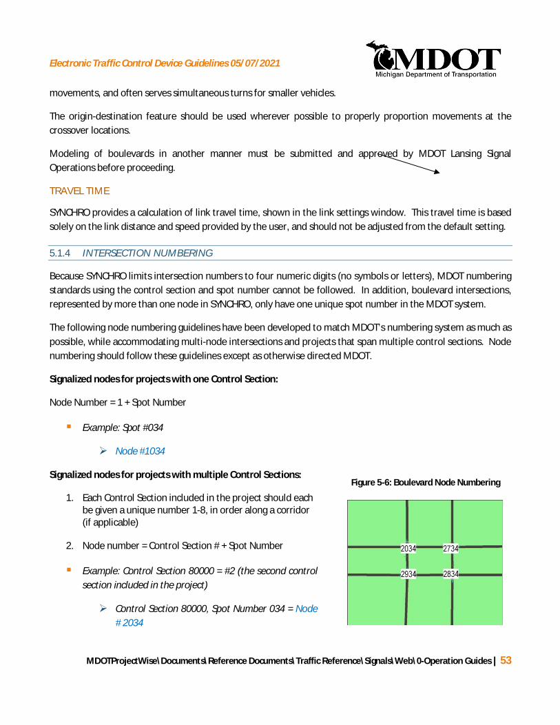
Electronic Traffic Control Device Guidelines 05/07/2021
MDOTProjectWise\Documents\Reference Documents\Traffic Reference\Signals\Web\0-Operation Guides | 53
Figure 5-6: Boulevard Node Numbering
movements, and often serves simultaneous turns for smaller vehicles.
The origin-destination feature should be used wherever possible to properly proportion movements at thecrossover locations.
Modeling of boulevards in another manner must be submitted and approved by MDOT Lansing SignalOperations before proceeding.
TRAVEL TIME
SYNCHRO provides a calculation of link travel time, shown in the link settings window. This travel time is basedsolely on the link distance and speed provided by the user, and should not be adjusted from the default setting.
5.1.4 INTERSECTION NUMBERING
Because SYNCHRO limits intersection numbers to four numeric digits (no symbols or letters), MDOT numberingstandards using the control section and spot number cannot be followed. In addition, boulevard intersections,represented by more than one node in SYNCHRO, only have one unique spot number in the MDOT system.
The following node numbering guidelines have been developed to match MDOT’s numbering system as much aspossible, while accommodating multi-node intersections and projects that span multiple control sections. Nodenumbering should follow these guidelines except as otherwise directed MDOT.
Signalized nodes for projects with one Control Section:
Node Number = 1 + Spot Number
§ Example: Spot #034
Ø Node #1034
Signalized nodes for projects with multiple Control Sections:
1. Each Control Section included in the project should eachbe given a unique number 1-8, in order along a corridor(if applicable)
2. Node number = Control Section # + Spot Number
§ Example: Control Section 80000 = #2 (the second controlsection included in the project)
Ø Control Section 80000, Spot Number 034 = Node# 2034

Electronic Traffic Control Device Guidelines 05/07/2021
MDOTProjectWise\Documents\Reference Documents\Traffic Reference\Signals\Web\0-Operation Guides | 54
Signalized nodes for boulevard intersections (more than one SYNCHRO node representing a single spotnumber):
1. The Northwest-most node should be numbered based on the standard numbering system above
2. Additional nodes should be numbered by varying the hundreds digit of the node number, counting backfrom “9” going counterclockwise.
§ Example (See Figure 5-6 on the previous page): Control Section 80000 (#2), Spot Number 034 is aboulevard/boulevard intersection (represented by four SYNCHRO nodes):
Ø Northwest-most Node = Node #2034
Ø Southwest-most Node = Node #2934
Ø Southeast-most Node = Node #2834
Ø Northeast-most Node = Node #2734
Unsignalized Nodes:
Unsignalized nodes (including sign-controlled intersections, bend nodes, external nodes, etc.) should benumbered in the 9000’s for ease of segregating during the reporting process. If the node is directly associatedwith an adjacent signal, such as the unsignalized node at a crossover, it should be numbered in association withthe signalized node similar to the way boulevard intersections are numbered.
5.1.5 STANDARD INTERSECTION PHASING SET-UP
The signal phasing used in SYNCHRO modeling should follow the phasing as documented on the timing permitwherever possible. In cases where the timing permit phasing is unclear, NEMA standard phasing sequenceshould be used. Since phases greater than eight (8) are rarely used, overlaps can be distinguished by codingthem as phase number 9 or higher.
When coding intersection phasing, it is imperative that the offset is referenced properly to the initial phase (orstart-up phase) in the controller. While maintaining agencies differ in their assignment of the initial controllerphase (based on major street, cardinal direction, etc.), the following standard should be applied to assureSYNCHRO network consistency.
Offsets should always be set to match the existing permit if possible, if this is not possible reference thebeginning of the green indication for phases 2+6.
Right turn movements should typically be coded as permissive unless there is a green arrow and no conflictingpedestrian movement.
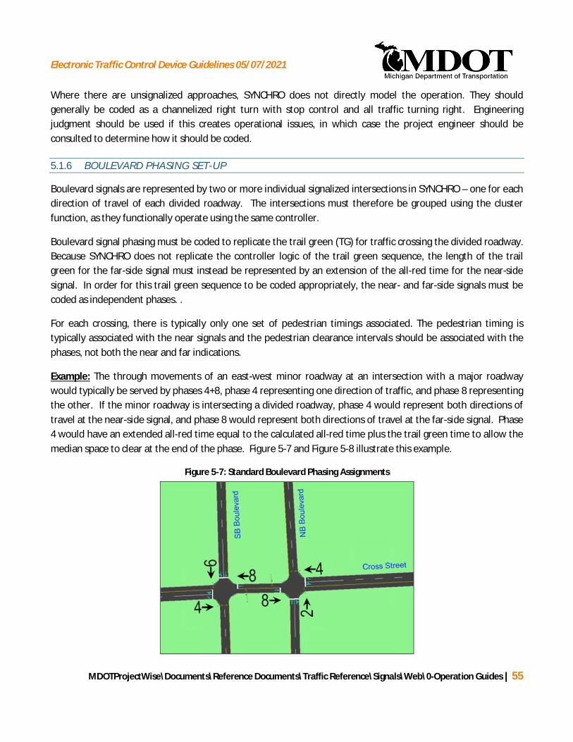
Electronic Traffic Control Device Guidelines 05/07/2021
MDOTProjectWise\Documents\Reference Documents\Traffic Reference\Signals\Web\0-Operation Guides | 55
Where there are unsignalized approaches, SYNCHRO does not directly model the operation. They shouldgenerally be coded as a channelized right turn with stop control and all traffic turning right. Engineeringjudgment should be used if this creates operational issues, in which case the project engineer should beconsulted to determine how it should be coded.
5.1.6 BOULEVARD PHASING SET-UP
Boulevard signals are represented by two or more individual signalized intersections in SYNCHRO – one for eachdirection of travel of each divided roadway. The intersections must therefore be grouped using the clusterfunction, as they functionally operate using the same controller.
Boulevard signal phasing must be coded to replicate the trail green (TG) for traffic crossing the divided roadway.Because SYNCHRO does not replicate the controller logic of the trail green sequence, the length of the trailgreen for the far-side signal must instead be represented by an extension of the all-red time for the near-sidesignal. In order for this trail green sequence to be coded appropriately, the near- and far-side signals must becoded as independent phases. .
For each crossing, there is typically only one set of pedestrian timings associated. The pedestrian timing istypically associated with the near signals and the pedestrian clearance intervals should be associated with thephases, not both the near and far indications.
Example: The through movements of an east-west minor roadway at an intersection with a major roadwaywould typically be served by phases 4+8, phase 4 representing one direction of traffic, and phase 8 representingthe other. If the minor roadway is intersecting a divided roadway, phase 4 would represent both directions oftravel at the near-side signal, and phase 8 would represent both directions of travel at the far-side signal. Phase4 would have an extended all-red time equal to the calculated all-red time plus the trail green time to allow themedian space to clear at the end of the phase. Figure 5-7 and Figure 5-8 illustrate this example.
Figure 5-7: Standard Boulevard Phasing Assignments

Electronic Traffic Control Device Guidelines 05/07/2021
MDOTProjectWise\Documents\Reference Documents\Traffic Reference\Signals\Web\0-Operation Guides | 56
Trail Green Time for the Far-Side Phase
Coded as Additional All-Red Time for the Near-Side Phase
Figure 5-8: Trail Green Sequence
Electronic Traffic Control Device Guidelines 05/07/2021
MDOTProjectWise\Documents\Reference Documents\Traffic Reference\Signals\Web\0-Operation Guides | 57
5.2 OPTIMIZATION
The automated optimization functions in SYNCHRO do not typically provide timings consistent with MDOT’spreferences. SYNCHRO output should be considered as a starting point for the optimization process. Care mustbe taken by the engineer to evaluate the SYNCHRO results and manually adjust the timings in the model basedon the following general guidelines.
5.2.1 SPLIT, CYCLE LENGTH, AND OFFSET SELECTION
§ Splits
When a pedestrian movement is equipped with pushbuttons, the vehicle split is typically entered as theminimum split in SYNCHRO as a starting point. Depending on the cycle length selected after evaluatingthe output of the SYNCHRO optimization, the minimum split in SYNCHRO may be increased toaccommodate the pedestrian split.
Generally, signal phase splits should be manually adjusted to favor the trunkline corridor (typically thehigher volume roadway), while maintaining acceptable LOS on the intersecting roadways. Specialattention should be paid to locations where a major arterial crosses the trunkline. In addition, signalizedcrossovers should generally be timed as an extension of the main intersection, with identical splits.
§ Cycle Lengths
MDOT signals typically operate on cycle lengths ranging from 60 seconds to 120 seconds, in 10 secondincrements.
The progression bands and phase splits must be reviewed during the process of selecting a cycle lengthas the splits and offsets that SYNCHRO provides are often impractical and/or provide excessive time tominor movements and thus may result in a less than ideal cycle length.
The network cycle optimization option should be selected, and the resulting performance indicesreviewed and reported as part of cycle length evaluation and selection.
Cycle lengths should generally be evaluated first based on the quality of progression for the trunklinecorridor, and secondly based on the resulting local intersection delay. Typically, cycle lengths thatprovide optimum progression for a high-volume trunkline will yield the best overall networkperformance.
Before choosing a cycle length that does not accommodate pedestrian split times, the following datamust be evaluated:
Ø Number of pedestrian pushbutton actuations during the 15 minute periods in the peak hours

Electronic Traffic Control Device Guidelines 05/07/2021
MDOTProjectWise\Documents\Reference Documents\Traffic Reference\Signals\Web\0-Operation Guides | 58
Ø Amount of time differential between minimum splits and programmed splits for all phases
Ø Correction mode being used for signals in coordination
Ø Number of cycles required for traffic signal controller to get back in step (correction)
Ø Impact to corridor traffic operations during correction time
Evaluation results may indicate that the peak period cycle length must accommodate the pedestriansplit time, but the off peak cycle length can be shorter based on vehicle split times, providing the longerpedestrian split times only upon pushbutton activation.
When considering a cycle length that does not accommodate the pedestrian split time, it is highlyrecommended to bench test a controller with anticipated pedestrian calls to ensure it gets back intostep as anticipated.
§ Offsets
Offsets obtained from traffic models should be considered as a starting point for signal retimingprojects. Field observation of the implemented offsets is critical to verify the efficacy of the proposedtiming. Offset adjustments may be needed due to slower traffic speeds or excessive queues.
Offsets should generally be adjusted to provide optimal progression for the predominant peak direction,while maintaining the best possible progression in the off-peak direction. If the cycle length remains thesame in optimized conditions as in existing conditions, a common reference point should be establishedfor ease of comparing the existing and optimized offset plan. A reference intersection should beselected (typically a major crossroad or a signal at one end of the corridor) and the existing offset at thatlocation held constant for the optimized condition, with all other offsets developed around it.
Selecting offsets for traffic signals with side-street vehicle detection requires engineering judgment.When an actuated side street phase gaps out, the coordinated main street phase will be serviced earlierthan planned. This early return to green may result in undesirable queuing and inefficient flow at acritical intersection or along the corridor. Early return to green is most likely to occur when side streetvolumes are low or sporadic. Adverse impacts from early return to green can sometimes be identified byobserving the simulation, or by viewing the time space diagram using 50% flows compared to 90% flows.
Techniques to mitigate early return to green include:
Ø Not allowing the early return to green if it will cause excessive queuing or adversely impactprogression at downstream intersection(s)
Ø Starting the green earlier on downstream intersection(s) to accommodate the early arrivals.

Electronic Traffic Control Device Guidelines 05/07/2021
MDOTProjectWise\Documents\Reference Documents\Traffic Reference\Signals\Web\0-Operation Guides | 59
· The more this adjustment is made, both in magnitude and the number of signals downthe corridor, the more potential adverse impact to the bandwidth, especially for two-way progression along a corridor.
· If a particular intersection is known to have consistently low side street volumes,consideration should be given to starting the green earlier at the next downstreamsignal. A general rule, based on driver expectation, is to avoid having drivers stop at twoconsecutive signals.
Offset selection may depend on the type of controller in use for the particular corridor being retimed.The following considerations are specific to the controller type:
Ø EPAC Controller
· Side street with vehicle detection:
o Select offsets using engineering judgment described above to address impactsof early return to green as required based on directional, flows, progressionbandwidths, time of day plan, and any critical intersections.
o The offsets on the timing permit should match the offsets shown in SYNCHRO.
Ø EPIC Controller
o If the controller loses step when the push button is activated (This will occur ifthe side street split is less than the minimum pedestrian split): EPIC controllerswon’t accommodate this type of operation. Adjust the splits to accommodatethe pedestrian timings while staying within the cycle length.
· If the controller does not lose step when the push button is activated (The start ofmainline green for EPIC controllers with push buttons will vary depending on if the pushbutton is activated. This will result in variable early greens depending on vehiclevolumes):
o If pedestrian actuations are infrequent, the SYNCHRO model and permit shouldbe based on not having pedestrian actuation. Typically, the start of the mainlinegreen will be at the beginning of the last interval and the SYNCHRO offset willcorrespond with the mainline green starting at the beginning of the last interval.However, the offset on the timing permit is based on the start of the firstinterval. The offset on the timing permit will need to be adjusted from what isshown in SYNCHRO to account for the early mainline green.
o If pedestrian actuations are frequent, the SYNCHRO model and permit should bebased on having pedestrian actuation. Typically, the start of the mainline greenwill be the start of the first interval and the SYNCHRO offset will correspondwith the mainline green starting at the beginning of the first interval. The offseton the timing permit should match the offset shown in SYNCHRO.

Electronic Traffic Control Device Guidelines 05/07/2021
MDOTProjectWise\Documents\Reference Documents\Traffic Reference\Signals\Web\0-Operation Guides | 60
5.2.2 ZONE ASSIGNMENT
In many cases it may be necessary or desirable to divide a project area into smaller signal zones in order toaccommodate different cycle lengths. Zone assignments must be approved by the MDOT project managerbefore proceeding with the optimization process. Proposed zone assignments are typically submitted in theform of a memo including a summary of the cycle length selection process. For larger projects, a meeting istypically held to discuss the zone assignments in the cycle length selection memo.
The following are examples of where separate zones should be considered:
§ Where differing volumes, speeds, or signal spacing indicate different cycle lengths would reduce overallnetwork delay.
§ Where a coupling index calculation indicates low benefit of coordinating two signals or zones.
§ Where a transition occurs from a median-divided to undivided roadway.
§ At a highly-congested intersection where congestion prevents progressive movement, even when acommon cycle length is used.
§ Where unique geometric conditions necessitate signal phasing not consistent with other intersectionswithin the project area.
§ Where a natural break in progression occurs, such as at a “T” intersection, the crossing of a freeway, or along segment of roadway (greater than 1.5 miles) without a signalized intersection.
5.2.3 COORDINATION WITH ADJACENT SIGNALS
Coordination with adjacent signals should be investigated under certain conditions so that the optimizationproject causes the least possible disruption to the surrounding signal network. The following are examples ofwhen coordination with adjacent signals should be investigated:
§ When a signal is closely adjacent (less than ¼ mile) to the project area/corridor.
§ When the optimized cycle length for the project area/zone is the same as the surrounding signalnetwork, and cross-progression could be accommodated.
§ When single intersections adjacent to the project area are left isolated (not functioning with any system)by the optimization project.
The extent of coordination may vary, from proposed changes in offsets to a complete re-timing. Every effortshould be made to determine coordination requirements in advance of proceeding with an optimization project.The extent of coordination should be discussed and determined in conjunction with the MDOT project manager.

Electronic Traffic Control Device Guidelines 05/07/2021
MDOTProjectWise\Documents\Reference Documents\Traffic Reference\Signals\Web\0-Operation Guides | 61
5.2.4 PHASING
MDOT applies a standard phasing sequence wherever possible in order to remain consistent with driverexpectations. Signal phasing should not be changed unless special conditions exist where other phasingstrategies are required, or would result in a substantial improvement over standard phasing.
The following phasing sequences are typically used:
§ Left-turns must LAG the through movement where a flashing red ball or 4th level left-turn arrowpermissive-protected phasing is used.
§ Left-turns should LAG the through movement where a flashing yellow arrow or 5 section permissive-protected phasing is used.
Ø Where there is significant benefit, the MDOT project manager may approve having the left turnphase LEAD.
§ Left-turns should LEAD the through movement where protected-only phasing is used.
5.2.5 MEASURES OF EFFECTIVENESS
Measures of Effectiveness (MOEs) should be evaluated to determine the effectiveness of the optimizationprocess. MOEs to be considered vary between the local intersection and network levels:
§ Local Intersections
Intersection control delay and level of service (Highway Capacity Manual method) should be evaluatedas the primary MOE at the local intersection level. Wherever possible, Level of Service (LOS) C or bettershould be achieved for all approaches. However, judgment should be used to balance approach levelsof service based on relative traffic demand. Where an intersection is running at or above theoreticalcapacity, the volume/capacity ratio should also be considered.
§ Network/System
Progression bandwidth should be evaluated as the primary MOE at the network/system level. Theoptimization should aim not only to provide the maximum bandwidth along major corridors, but toposition the band to provide progression for the leading vehicles in the platoon (leading edgebandwidth) wherever possible.
While other MOEs should be evaluated as part of the optimization and reporting process (see Section 5.3.3), theabove MOEs should be considered the most important when making optimization decisions and adjustments.

Electronic Traffic Control Device Guidelines 05/07/2021
MDOTProjectWise\Documents\Reference Documents\Traffic Reference\Signals\Web\0-Operation Guides | 62
5.2.6 TIME-OF-DAY SCHEDULES
The time-of-day schedule for the project area/zone should be updated as part of the optimization process todesignate when the various timing plans should be in operation. The following guidelines should be followed indetermining the time-of-day schedule:
§ Signals typically operate under three timing plans: AM peak period, PM peak period, and a mid-day/off-peak/weekend plan.
§ 24-hour counts should be used to determine when timing plan changes should occur based on the trafficflow pattern. Figure 5-9 presents an example of a typical 24-hour traffic flow pattern of an averageweekday, and illustrates where timing plan changes may be appropriate.
§ The time-of-day schedule should be the same for all signals within a zone in order to maintaincoordination, except when signals change in and out of flash operation.
§ Certain locations may require special mid-day, night, or weekend timing plans to accommodate uniqueconditions, such as school dismissal or shift changes. In such cases, coordination should be maintainedwhenever possible with adjacent signals operating on a standard schedule.
§ When a signal comes out of flash mode or changes dial/splits, it must go thru a period of correctionwhere the controller adjusts the timings to move the offset to the desired time. During this correctionthe offsets tend to be random and progression will often be poor. Depending on the cycle length, howmuch the offset needs to be adjusted and how much correction the controller can make per cycle, thiscan take multiple cycles and last for as much as 10-15 minutes. In the AM time period, it is oftenbeneficial to start the timing plan while volumes are still relatively low but growing quickly. This allowsall the controllers to be coordinated when the peak volumes arrive. There may be situations where thisis beneficial for the PM time period, but the midday volumes are typically substantially higher than theearly morning volumes and the PM peak is typically more of a gradual increase in volumes as opposed tothe sharp spike typically seen in the AM time period.
At locations with current flash schedules, the period(s) of flash operation should be reviewed based on 24-hourvolume data. While flash schedule is not explicitly addressed in the current edition of the Michigan Manual ofUniform Traffic Control Devices (MMUTCD), MDOT’s internal guideline on setting flash schedule, consistent withdirection set forth in the 1994 MMUTCD, which follows:
“When for a period of four or more consecutive hours any traffic volume drops to 50percent or less of the stated volume warrants, it is desirable that flashing operationbe substituted for conventional operation for the duration of such periods. However,such flashing operation should be restricted to no more than three separate periodsduring each day.”
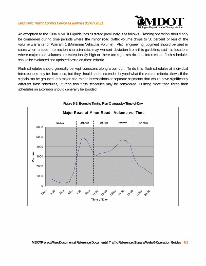
Electronic Traffic Control Device Guidelines 05/07/2021
MDOTProjectWise\Documents\Reference Documents\Traffic Reference\Signals\Web\0-Operation Guides | 63
An exception to the 1994 MMUTCD guidelines as stated previuosly is as follows. Flashing operation should onlybe considered during time periods where the minor road traffic volume drops to 50 percent or less of thevolume warrants for Warrant 1 (Minimum Vehicular Volume). Also, engineering judgment should be used incases when unique intersection characteristics may warrant deviation from this guideline, such as locationswhere major road volumes are exceptionally high or there are sight restrictions. Intersection flash schedulesshould be evaluated and updated based on these criteria.
Flash schedules should generally be kept consistent along a corridor. To do this, flash schedules at individualintersections may be shortened, but they should not be extended beyond what the volume criteria allows. If thesignals can be grouped into major and minor intersections or separate segments that would have significantlydifferent flash schedules, utilizing two flash schedules may be considered. Utilizing more than three flashschedules on a corridor should generally be avoided.
Major Road at Minor Road - Volume vs. Time
0
1000
2000
3000
4000
5000
6000
Time
1:00
3:005:00
7:00
9:0011:0
013
:0015:0
017
:0019
:0021:0
023
:00
Time of Day
Volu
me
AM Peak PM PeakOff-Peak Off-PeakOff-Peak
Figure 5-9: Example Timing Plan Changes by Time-of-Day

Electronic Traffic Control Device Guidelines 05/07/2021
MDOTProjectWise\Documents\Reference Documents\Traffic Reference\Signals\Web\0-Operation Guides | 64
5.2.7 FLASH SCHEDULES
The flash schedule is determined by using the traffic volumes and Warrant 1 in the MMUTCD 1994 guidelineswhich states, “When for a period of four or more consecutive hours any traffic volume drops to 50 percent orless of the stated volume warrants, it is desirable that flashing operation be substituted for conventionaloperation for the duration of such periods. However, such flashing operation should be restricted to no morethan three separate periods during each day.” Generally flashing operation should be considered during timeperiods where the minor road traffic volume drops to 50% or less of the volume warrants for Warrant 1(Minimum Vehicular Volume). There are a number of situations where flash operation should be referred to theMDOT project manager for comment prior to making a decision.
§ If the major street has significant volume that would make it difficult for minor road traffic to enter theintersection, a flash schedule may not be desirable.
§ For signals in residential areas or with evening pedestrian activity, consider delaying the beginning of theflash schedule until at least 10:00 PM, especially for roadways having more than 3 lanes and speedsgreater than 35 Mph.
§ If the major road volume is below 50% of the warranting volumes but the minor road volume is not,consideration of utilizing a flash schedule may be considered if it would allow for a more consistent flashschedule along the corridor.
§ Flash operation should generally be avoided in cases when unique intersection characteristics may makeit undesirable, such as locations where there are sight distance restrictions.
Intersection flash schedules should be evaluated and updated based on these criteria. See Table 5-1 forminimum vehicular volumes.
Table 5-1: Warrant 1 (Minimum Vehicular Volume)
Minimum Vehicular VolumeNumber of lanes for moving
traffic on each approachVehicles per hour on
major street (total of bothapproaches)
Vehicles per hour onhigher-volume minor-street
approach (one directiononly)
Major Street Minor Street 100%a 80%b 70%c 100%a 80%b 70%c
1................. 1................. 500 400 350 150 120 1052 or more... 1................. 600 480 420 150 120 1052 or more... 2 or more ... 600 480 420 200 160 1401................. 2 or more .... 500 400 350 200 160 140
a Basic minimum hourly volume.c May be used when the major-street speed exceeds 70 km/h or exceeds 40 mph or in an isolated community with a population of less than 10,000.
Electronic Traffic Control Device Guidelines 05/07/2021
MDOTProjectWise\Documents\Reference Documents\Traffic Reference\Signals\Web\0-Operation Guides | 65
For determination of Flash Schedules, MDOT will typically consider left-turn and right-turn lanes as individuallanes for moving traffic. Therefore, if an approach has 1 through lane and 1 left-turn lane, it is considered a 2-lane approach for the purposes of determining flash schedules.
Even though it is allowable for an intersection to be in flash based on the volume criteria, it is generally desirableto keep the entire corridor on the same flash schedule. This may reduce the duration of the flash schedule atsome locations. This should not be used to justify putting a signal into flash when it does not meet the 50% ofthe warranting volumes criteria.
It sometimes is beneficial to provide two schedules such as a corridor where there are a small number of busyintersections that allow for a relatively short flash schedule and the remainder could have a longer flashschedule.
Any locations where the flash schedule is increased beyond the existing should be highlighted so the projectmanager can verify if the change is acceptable.
Set all flash schedules beginning at midnight to 00:01 so as not to interfere with a midnight sync pulse orrecovery from a power outage.
5.3 MICROSIMULATION
Microsimulation should be conducted using SimTraffic to further evaluate the network performance both beforeand after optimization. This evaluation should focus on the effectiveness of progression along major corridorsand identification of potential storage issues. The following sections document specific procedures to befollowed when conducting microsimulation.
5.3.1 SIMULATION TIMEFRAME
A full hour of analysis is typically used for all microsimulation analyses, in addition to an adequate period fornetwork seeding. However, duration may be evaluated and determined on a project-by-project basis, assimulation of large networks may become prohibitively long.
NETWORK SEEDING PERIOD
The network seeding period must at a minimum be long enough for one vehicle to travel from one entry point ofthe network to the farthest exit point of the network. This length of time should be approximated based ondistance, speed limits and consideration of signal density and congestion within the network. No data should berecorded during the seeding interval.

Electronic Traffic Control Device Guidelines 05/07/2021
MDOTProjectWise\Documents\Reference Documents\Traffic Reference\Signals\Web\0-Operation Guides | 66
ANALYSIS PERIOD
The analysis hour should reflect fluctuationsin traffic flow over an hour period, asrepresented by the Peak Hour Factor (PHF).The PHF defines the intensity of traffic flowduring the peak 15-minutes of the hourperiod, relative to the remainder of thehour. The location of the peak 15-minuteperiod within the peak hour may vary, evenwithin a single corridor. However, undernormal conditions, the peak 15-minuteperiod may be estimated to occur within themiddle two 15-minute intervals of the hour.
In order to reflect this variation in trafficflow over the hour, the analysis hour shouldbe divided into three distinct intervals – a15-minute pre-peak interval, a peak 15-minute interval, and a 30-minute recovery interval. The PHF should be applied during the peak 15-minuteinterval only. An anti-PHF (an inverse of the PHF used to reduce volume levels during the off-peak intervals)should be applied during the pre-peak and recovery intervals. Figure 5-10 illustrates this interval set-up.
5.3.2 CALIBRATION AND VALIDATION
The SimTraffic model of the existing conditions must be calibrated and validated to actual field conditions beforefurther analysis is conducted. In addition to performing adjustments to the simulation parameters to betterreflect nuances experienced in the field, this process serves as an opportunity to validate the accuracy of theSYNCHRO model inputs.
SimTraffic model outputs should be compared against any available and comparable field data to determine thevalidity of the model results. On a typical project, this would be traffic volumes served. A comparison of actualturning-movement counts that were input into SYNCHRO and the SimTraffic model results can be done using theSimTraffic VOLUME EXITED report. This report should be conducted to assure that the actual volume levelsobserved in the field are being replicated by the SimTraffic model. The greater of ±10 percent or ±20 vehicles isconsidered a reasonable threshold for model validation. Figure 5-11 illustrates an example report to be includedin the final report (see Section 5.4.2). The report shows the volume exited, the volume input, as well as thepercent of volume exited. If volume on a certain approach is very low, usually the +20 vehicle rule will apply.
Figure 5-10: Example SimTraffic Time Interval Setup

Electronic Traffic Control Device Guidelines 05/07/2021
MDOTProjectWise\Documents\Reference Documents\Traffic Reference\Signals\Web\0-Operation Guides | 67
Once calibrated andvalidated, any adjustedparameters are stored in aSimTraffic configuration file(extension .sim for SimTrafficversion 7). If the SYNCHROfile is modeled in SimTrafficwithout the appropriateconfiguration file in the samedirectory, SimTraffic will usedefault parameters, therebynegating the calibration andvalidation process. Therefore,appropriate .st7 files, representing the calibration of existing conditions, should be used when modelingoptimized conditions, and should accompany all file transmittals.
5.3.3 MEASURES OF EFFECTIVENESS
SimTraffic Measures of Effectiveness (MOEs) should be collected and evaluated as a means of further assessingthe results of the optimization process. The following MOEs should be reviewed during the analysis process,and should be included in the final report (see Section 5.4.2):
§ Total Network Delay
§ Average Network Speed
§ Total Network Travel Time
§ Total Network Stops
5.4 DOCUMENTATION
5.4.1 PROJECT BENEFITS ANALYSIS
A project benefits analysis should be performed for each project, quantitatively evaluating conditions bothbefore and after the new timings are in place. This analysis will typically require collection of travel time orother data both before and after implementation. Specific procedures, however, will vary by project, and will bedetermined in conjunction with the MDOT project manager at the beginning of the project.
The benefit analysis can be performed using two different methodologies:
Figure 5-11: Sample Model Validation Log

Electronic Traffic Control Device Guidelines 05/07/2021
MDOTProjectWise\Documents\Reference Documents\Traffic Reference\Signals\Web\0-Operation Guides | 68
§ The preferred method for corridors is to utilize PC-Travel data from before- and after-travel time runs.MDOT provides a Signal Optimization Benefit/Cost Analysis Spreadsheet. Data from PC-Travel reportscan be quickly entered into this spreadsheet along with traffic volume information to generate abenefit/cost summary for the project.
§ A second benefit analysis can be performed using results from SimTraffic. This method should be usedwhen studying isolated intersections, small groupings of signals (typically 5 or fewer), or any othersituation where before or after travel time runs are unavailable. The benefit analysis uses thefollowing MOE’s from SimTraffic:
Ø Stop Delay (sec/veh)
Ø Travel Time (hr)
Ø Average Speed (mph)
Ø Fuel used (gal)
Ø HC Emissions (g)
Ø CO Emissions (g)
Ø NOx Emissions (g)
Ø Vehicles Exited
Several assumptions regarding average values have been made. These values are as follows:
§ Average Cost of Fuel: Obtain an average annual fuel cost from a reliable source such ashttp://www.bls.gov/regions/midwest/news-release/averageenergyprices_detroit.htm and confirm withMDOT Signals Unit
§ Average Number of Work days per Year: 250
§ Average Vehicle Occupancy: 1.1
§ Average Value of Time per Individual: Should be an average based on the Federal HighwayAdministration (FHWA) publication number FHWA-SA-98-079, "Life-Cycle Cost Analysis in PavementDesign." Currently, MDOT updates these costs yearly using the Consumer Price Index (CPI).
These values should be verified with the MDOT PM prior to completing the analysis. Volume counts for eachpeak hour should also be input into the analysis.

Electronic Traffic Control Device Guidelines 05/07/2021
MDOTProjectWise\Documents\Reference Documents\Traffic Reference\Signals\Web\0-Operation Guides | 69
5.4.2 PROJECT REPORT
Each optimization project should include a final report documenting the project process and results, as well asall data collected for the signal timing effort. The following sections describe the required documentation.
MEASURES OF EFFECTIVENESS DOCUMENTATION
All Measures of Effectiveness (MOEs) should be summarized in a tabular format within the project report forease of review. The summary of MOEs prepared for the optimization analysis should include a comparisonbetween existing and optimized conditions results. Following are sample formats for MOE summary tables:
Table 5-2: Comparison of Optimized and Existing Intersection Operations - Zone 1, PM Peak Hour
Intersection Existing Condition Optimized Condition Change(sec/veh)Delay (sec/veh) LOS Delay (sec/veh) LOS
Main Street/Elm Street 47.6 D 41.3 D -6.3Main Street/Walnut Street 24.9 C 18.2 B -6.7
Source: SYNCHRO
Table 5-3: Comparison of Optimized and Existing Network Operations - Zone 1, PM Peak Hour
MOE Existing Condition Optimized Condition Change (%)Total Delay (hours) 370 320 -14%Total Stops 15000 13000 -13%Total Travel Time (hours) 600 500 -17%Average Speed (mph) 27 34 +26%
Source: SimTraffic
REPORT ORGANIZATION
Optimization project reports should generally be organized into the following sections:
Project Summary
The first page of the report should provide a one-page summary table detailing pertinent project scope andresults information. The summary should include the following information:

Electronic Traffic Control Device Guidelines 05/07/2021
MDOTProjectWise\Documents\Reference Documents\Traffic Reference\Signals\Web\0-Operation Guides | 70
SIGNAL OPTIMIZATION PROJECT SUMMARY
MDOT Job Number JN 50000CRoute Number and Name M-1000 Elm AvenueControl Section(s) CS 90000Location (City/Township, County) Anywhere Twp, Michigan CountyProject Limits (Cross-Streets) Main Street to Oak StreetProject Limits (Mileposts) 10.2 to 16.7Field Study Results AM Peak Mid-Day PM PeakTravel Time Reduced by (minutes): Northbound 1.2 0.4 2.2
Southbound 1.0 0.1 3.1Stopped Time Reduced by (minutes): Northbound 0.8 0.2 1.6
Southbound 0.6 0.2 2.7Speed Increased by (mph): Northbound 5.0 2.0 6.0
Southbound 4.0 1.0 5.0Daily Vehicle-Hours of Travel Reduced by: 500 Vehicle-HoursDaily Fuel Consumption Reduced by: 300 GallonsDaily Pollutant Emissions Reduced by: 1000 Pounds VOC, NOxDaily Time and Fuel Savings: $1,400 DollarsAnnual Time and Fuel Savings: $350,000 DollarsProject Cost: $100,000 DollarsFunding Source: CMAQAverage Daily Traffic: 20,000 Vehicles per DayAnnual Benefit/Cost Ratio: 3.5
If the project incorporates multiple corridors, a summary for the entire project should be incorporated. The FieldStudy Results would not be listed. The summary for the individual corridors should be included in an appendixseparate for each corridor.
Table of Contents
Following the Project Summary, provide a table of contents detailing page numbers of reportsections, tables and figures.
1.0 Introduction
The Introduction section should include a brief description of the project area, including a map,and a list of intersections included in the analysis.
Electronic Traffic Control Device Guidelines 05/07/2021
MDOTProjectWise\Documents\Reference Documents\Traffic Reference\Signals\Web\0-Operation Guides | 71
2.0 Data Collection
The Data Collection section should include a description of the data collected, including dates.Any unusual circumstances surrounding the data collection effort should be identified, such asconstruction, weather conditions, etc.
3.0 Existing Operations Analysis
The Existing Operations Analysis section should document the following:
§ SYNCHRO analysis results in tabular form
§ The SimTraffic model calibration and validation process
§ SimTraffic analysis reports in tabular form
4.0 Crash Analysis
The Crash Analysis section should identify critical crash locations and discernable crash patternsat critical locations.
5.0 Optimization Analysis
The Optimization Analysis and Results section should document the following:
§ A brief description of the optimization process, including cycle length selection (Mapsshould be provided in cases where multiple cycle lengths are employed during the sametime period).
§ Discussion of any proposed phasing modifications
§ SYNCHRO analysis results in tabular form
§ SimTraffic analysis results in tabular form
7.0 Project Implementation and Benefits
The Project Implementation and Benefits section should document the following:
§ A discussion of the implementation process, including field review and necessary timingmodifications.
§ Project benefits analysis summary that includes a comparison of before and after travel timeruns.
§ Identification of any items for consideration that were mitigated (or may potentially bemitigated) as a result of this project.
Electronic Traffic Control Device Guidelines 05/07/2021
MDOTProjectWise\Documents\Reference Documents\Traffic Reference\Signals\Web\0-Operation Guides | 72
8.0 Items for Further Consideration
Include any recommendations to further improve operations or safety, including equipmentupgrades, geometric or striping reconfiguration, addition or deletion of signal phases, removalof signals due to lack of warrant, or other modifications. Also make a note where further studywould be required to determine the exact scope or effectiveness of potential improvements.
Potential items to identify for improvement may include:
§ Operations and safety, i.e. signal timing/phasing, turn restrictions, lane assignment,adjacent parking.
§ Geometry that impacts both traffic operations and safety, i.e. lane geometry, sight distanceissues, offset vehicle paths.
NOTE: An advanced submittal regarding items for consideration should only be submitted if there is acritical item that needs to be addressed through the retiming of the signal.
Appendix A: Traffic Volume and Travel Time Data
§ A sample MDOT formatted traffic volume data submittal and guidelines for the submittal ofMDOT formatted traffic volume data is included in Appendix A of this document
Appendix B: Intersection Inventory and Condition Reports
§ A sample inventory form and instructions for data collection are provided in Appendix B ofthis document.
Appendix C: Timing Permits
Appendix D: SYNCHRO and SimTraffic Reports
§ A sample SYNCHRO analysis report format is included in Appendix D of this document,including HCM reports
o For models containing two or more coordinated signals, include 90%tile bandwidthand 90%tile flow printouts.
§ A sample SimTraffic analysis report format is included in Appendix D of this document.
Appendix E: Project Benefits Analysis Spreadsheet
The report should be prepared in a concise manner, using maps, figures and tables where appropriate to bestconvey the information.
Electronic Traffic Control Device Guidelines 05/07/2021
MDOTProjectWise\Documents\Reference Documents\Traffic Reference\Signals\Web\0-Operation Guides | 73
6 DATA COLLECTION
Data collection includes traffic counts, intersection geometry, speed, and crash data. High quality data is criticalto effective traffic signal timing.
Data collection procedures for signal retiming should be documented in a data collection plan, including types ofinformation to be collected, acceptable collection timeframes, and other procedures as required by the specificproject.
The data collection processes and procedures presented herein are based on procedures outlined in the ITEManual of Transportation Engineering Studies. The ITE manual should be consulted in the event that additionaldata collection is required beyond what is outlined in this chapter.
6.1 TRAFFIC COUNTS AND PEAKING CHARACTERISTICS
Peak period, off-peak, and daily traffic counts are all necessary in order to fully understand the trafficcharacteristics of an intersection. The following presents guidelines for the conduct of these counts, includingwhen and where they are required, and interpretation and processing of the data.
6.1.1 GENERAL GUIDELINES
Traffic volume data can vary significantly based on day of the week, and is often highly sensitive to holidays andspecial events. In order to maintain consistency and to assure counts are reflective of typical conditions, trafficvolume data collection should adhere to the following general guidelines:
§ Counts should be taken on Tuesdays, Wednesdays and Thursdays only, unless special circumstancesrequire data for another day of the week.
§ Counts should not be taken during periods of inclement weather (rain, snow or fog events) that mayresult in atypical traffic flow conditions.
§ Counts should not be taken at any time during a week that includes one of the following holidays:
Ø Martin Luther King Jr. Day
Ø Presidents Day
Ø Good Friday
Ø Easter Sunday
Ø Memorial Day
Ø Independence Day
Ø Labor Day
Ø Thanksgiving
Ø Christmas
Ø New Years Eve/Day
§ Counts should not be taken on the day of the above holidays or any other national holidays.
§ Whenever possible, counts should be taken while schools are in session.

Electronic Traffic Control Device Guidelines 05/07/2021
MDOTProjectWise\Documents\Reference Documents\Traffic Reference\Signals\Web\0-Operation Guides | 74
§ In tourist areas, the seasonal variation should be discussed with the Project Manager when setting upthe data collection schedule.
§ Consideration should be given to the two-week summer “shut-down” period observed by majorautomakers and suppliers in the state. Shut-down may lead to lower than normal traffic volumes in highemployment areas, or higher than normal volumes in recreational areas. Depending on the projectlocation, data collection during the shut-down period should be avoided whenever possible.
6.1.2 24-HOUR VOLUME COUNTS
24-hour volume counts provide the basis with which to understand the changes in traffic flow over the course ofa typical weekday. They will be used to determine when changes in timing programs should occur throughoutthe day, and to identify if and when a flash operation is appropriate. The following guidelines should be appliedwhen conducting 24-hour approach counts:
§ Counts should be taken at all intersection approaches for a period of two weekdays within a typicalMonday through Thursday period.
§ Counts should be taken on all approaches at locations that currently operate under flash control at anytime or currently operate with a special weekend timing plan for a period of seven (7) days, including alldays of the week.
§ If an interchange lies within the corridor, machine counts should be taken on the ramps (signalized andunsignalized).
§ Counts should be provided in 15 minute intervals.
§ Additional counts may be performed at the suggestion of the Engineer as warranted by field conditions.
On roadways that utilize directional crossovers, machine counts may be utilized in lieu of manual counts.Recognizing that the timing at crossovers is often a direct reflection of the timing at the nearest majorintersection, machine counts can often collect all of the necessary data. A cost savings may be achieved byutilizing machine counts without manual counts at some crossovers. See Figure 6-1 for placement of tubecounters.
§ Machine counts are typically higher than manual counts since machines count axles not vehicles. As aresult, the machine counts and the manual counts should be compared by time period at the primaryintersection to determine the variance between them. The machine counts at the crossover should beadjusted accordingly to balance with the main intersection.
§ At locations where there is no driveway or minor road coming into the crossover, machine counts willtypically provide sufficient data for the analysis. At locations where the crossover turns into a drivewayor minor road, a judgment should be made regarding the likelihood that it will control the signal timings

Electronic Traffic Control Device Guidelines 05/07/2021
MDOTProjectWise\Documents\Reference Documents\Traffic Reference\Signals\Web\0-Operation Guides | 75
Figure 6-1: Tube Counters on Boulevards
or have timings independent of adjacent signals. If likely to control the timings, full manual countsshould be taken.
§ It is preferable to measure the crossover traffic in the left turn lane as opposed to the crossover itself.Tubes typically count axels and convert the results into the number of vehicles. This is bestaccomplished by placing the tube at a right angle to the direction of traffic. If placed in the crossover,vehicles may cross at an angle and individual wheels may be counted substantially increasing themeasured volume.
6.1.3 TURNING-MOVEMENT COUNTS
Turning-movement counts should be collected during the following periods, unless special circumstances existthat warrant additional counting periods:
§ AM Peak Period: 7:00AM – 9:00AM
§ Mid-Day Period: 11:00AM – 1:00PM
§ PM Peak Period: 2:00PM – 6:00PM
Electronic Traffic Control Device Guidelines 05/07/2021
MDOTProjectWise\Documents\Reference Documents\Traffic Reference\Signals\Web\0-Operation Guides | 76
For the AM and PM peak periods where multiple hours of data are collected, each intersection will have aunique peak hour within the multi-hour count period. To determine which volumes should be used, evaluatethe Peak Hour for each intersection and use the volumes that correspond to this hour.
Peak hour factors should be calculated by intersection approach. For example, if the total approach volume (L +T + R) over the study hour is 1000, and the peak 15-minute approach volume (L + T + R) is 300, the peak hourfactor applied to all movements for that approach is 1000/(4*300) = 0.83. For Dummy nodes, the PHF should beset based on the average of the upstream and downstream PHF.
Truck counts should be included in the total with the main counts when reporting, even though they have aseparate tab on the traffic counts spreadsheet.
6.1.4 PEDESTRIAN COUNTS
Pedestrian counts should be included as part of intersection turning movement counts. Pedestrian counts are ofparticular importance at locations where pedestrian volumes play a significant role in intersection operation.Pedestrian counts should be taken during time periods as the turning-movement counts and recorded in 15minute increments. Additional notes should be taken if multiple pedestrians are seen crossing in groups.
When reported, pedestrian movements are categorized under the vehicular movement that they are in conflictwith. For example, a pedestrian that crosses the south leg of an intersection will be counted as a northboundpedestrian. Similarly, a pedestrian that crosses the east leg is considered a westbound pedestrian
6.2 GAP STUDIES
Gap studies are typically conducted to get a better idea of how vehicles react when faced with an unprotectedmovement or to determine if pedestrians can safely cross a roadway. In order to make an unprotectedmovement, vehicles and pedestrians must find a “gap” in the conflicting traffic. Two factors are important indetermining if there are enough gaps in traffic:
1. The minimum acceptable gap, otherwise known as the critical gap.
2. The actual gap that is present in opposing traffic.
To measure vehicle gaps in the field, a reference point is selected near the intersection, and the time is recordedevery time the front bumper of a car hits that same point. This allows a time in seconds to be calculatedbetween each vehicle. The data is then grouped into bins such that the engineer can see how many gaps wereavailable from 0 to 2 seconds, 2 to 4 seconds, and so on.
For pedestrian crossings, Warrant 5 (School Crossing) in the MMUTCD provides a formula to determineacceptable gaps.
Electronic Traffic Control Device Guidelines 05/07/2021
MDOTProjectWise\Documents\Reference Documents\Traffic Reference\Signals\Web\0-Operation Guides | 77
6.3 DELAY/QUEUING
Comprehensive delay and queue measurement is a time consuming and expensive process. A simplified methodused by MDOT is as follows:
Every five minutes during a red phase, an observer at one approach, determines how many cars are in thequeue. At that time a stop watch is started. The time is recorded when the last car clears the intersection. Thiswill provide two sets of data points. The length of the queue in number of vehicles, and the time in seconds ittakes a vehicle to clear the intersection.
6.4 SPEED STUDIES
Speed is an important factor in determining signal progression. Spot speed studies are the easiest to conduct.They should generally be taken away from intersection approaches so that traffic is free flowing and notimpacted by intersection control. There are many ways to measure speed but the most common are radar (orlaser) units or pneumatic tubes. Measuring with radar can be accurate, but generally hose counts are preferredas drivers tend to react to an observer with a radar unit by slowing down.
6.5 TRAVEL TIME DATA
While simulation models predict the impacts of optimization, there are often situations where field conditionsdo not match the predictions. Field reviews including travel time runs are useful to calibrate the existingconditions models and to verify the improvements due to optimized signal timings.
Travel time data will typically be required to support the evaluation of before- and after-conditions. The extentof study and data to be collected will be determined at the beginning of a project in conjunction with the MDOTproject manager. Travel time runs should be performed when six or more signals are being coordinated and areno more than 80 seconds travel time apart. Additional corridors may require travel time runs as requested bythe MDOT project manager. There are various methods in which travel time data can be collected, includingGPS tracking software, Bluetooth/Wi-Fi receivers and detectors, and other software capable of monitoring real-time and historical travel times. All are acceptable methods, however the method used on each project must beapproved by the MDOT PM prior to collection. Travel time data collection should follow the proceduresoutlined in the ITE Manual of Transportation Engineering Studies, unless otherwise directed by the MDOTproject manager. An average of the data must be obtained per time period (i.e. 5 runs in each direction ormultiple times of day for alternative methods).
6.6 INTERSECTION GEOMETRY AND EQUIPMENT
A field inventory of intersection geometry and equipment should be conducted at each study intersection.Whenever possible, MDOT or the maintaining agency will provide available as-built drawings for use in verifying

Electronic Traffic Control Device Guidelines 05/07/2021
MDOTProjectWise\Documents\Reference Documents\Traffic Reference\Signals\Web\0-Operation Guides | 78
field data. MDOT has developed a standardized inventory form that includes the information required todevelop accurate models.
Intersection inventory forms should adhere to a standard naming convention unless otherwise discussed inadvance with the MDOT project manager. The following is the standard file naming convention:
Control Section # - Spot # -“ Inventory” - Month-Day-Year–Vx.pdf
Example: The Woodward Avenue (M-1) corridor within the city of Detroit (Control Section 82400) is beinginventoried. The spot number in this case is 025. The date should be the date the inventory data was collected.If minor updates are made the version number should be updated.
File Name = 82400-025-Inventory - 01-01-2001-V1.pdf
6.6.1 INTERSECTION INVENTORY AND CONDITION FORM
A sample inventory form is included in Appendix B along with instructions for data collection. In general, theinventory should include the following information:
§ Intersection Location and Number
§ Street Naming
§ Geometry
§ Operations
§ Equipment
§ Signal Phasing
§ Intersection Layout Diagram
§ General Comments
6.6.2 INTERSECTION PHOTOGRAPHS
Photographs of each intersection should be taken to ensure the accuracy of recordings on the Inventory Formand as a source of additional information. The approach photo should be taken from a position where allapproach and departure lanes and signal equipment is visible. If this cannot be done with one photo or there areunusual features, additional photos should be taken to capture pertinent data.
Intersection photographs should be taken in all approach directions (If there is a one way road or departingramp include the opposite approach also) and labeled accordingly in the Approach Direction (Northbound,Southbound, Eastbound, Westbound, etc). When submitting intersection photographs, all photographs for a
Electronic Traffic Control Device Guidelines 05/07/2021
MDOTProjectWise\Documents\Reference Documents\Traffic Reference\Signals\Web\0-Operation Guides | 79
single intersection should be contained within one file. A PDF form has been developed for consistency. Withinthe document, photographs are to be labeled with their corresponding directional approach and inserted intothe document as follows:
§ Major Approach Photographs
§ Minor Approach Photographs
§ Miscellaneous Approach Photographs
If the intersection is a boulevard take separate photos for both the “near” and “far” approaches. Place the“near” intersection photographs first and the “far” intersection photographs second in the PDF document.
Intersection photographs should adhere to a standard naming convention unless otherwise discussed in advancewith the MDOT project manager. The following is the standard file naming convention:
Control Section # - Spot # - “Photo” - Month-Day-Year.pdf
Example: The Woodward Avenue (M-1) corridor within the city of Detroit (Control Section 82400) is beinginventoried. The spot number in this case is 025. The date that the photo was taken will also be included in thefile name.
File Name = 82400 – 025 – Photo – 01-01-2008.pdf
6.7 HEAVY VEHICLE VOLUME
While it is preferable to collect actual heavy vehicle counts, MDOT’s Average Daily Traffic (ADT) Map andCommercial Vehicle ADT Map can be used to verify the heavy vehicle counts. Both are available on the MDOTwebsite at WWW.MICHIGAN.GOV/MDOT under “Reports, Publications, and Specs.” A default value of two-percent heavy vehicles should be assumed for other intersection movements where data is not available.
The heavy vehicle percentage (HV%) is typically calculated by approach and not for an individual movement. Anexception to this can be made if a particular movement has a higher percentage of truck traffic than the othersin the approach (e.g., near the Ambassador Bridge there are certain turning movements that feed into thefreeway system and thus have very high truck volumes associated with them).
6.8 BUS BLOCKAGES
Bus blockages can have a measurable impact on intersection performance along corridors with high transit use.A number of bus blockages per hour should be determined or estimated at intersections with bus stops in thenear upstream or downstream vicinity. Local transit providers should be contacted when possible to determinebus routing and headways during analysis hours.

Electronic Traffic Control Device Guidelines 05/07/2021
MDOTProjectWise\Documents\Reference Documents\Traffic Reference\Signals\Web\0-Operation Guides | 80
6.9 PARKING MANEUVERS
Parking maneuvers adjacent to the travel lanes should be estimated based on number of spaces, nearby landuse composition, and parking time and duration restrictions (where applicable). A default of 10maneuvers/hour should be assumed under typical conditions with an adjacent parking lane.
6.10 CRASH DATA
Crash data, if available, should be collected for study intersections in order to identify any crash patterns thatmay be correctable through signal timing or equipment modifications. While most data will be available throughMDOT, the assistance of local agencies may be required in some cases. Crash data should be obtained for thelast three consecutive years of complete crash data. Locations where fatal crashes have occurred may justifyadditional years of analysis and should be verified with the MDOT project manager.
It will be at the discretion of the MDOT project manager to determine whether a crash analysis is warranted andshould be conducted.
Electronic Traffic Control Device Guidelines 05/07/2021
MDOTProjectWise\Documents\Reference Documents\Traffic Reference\Signals\Web\0-Operation Guides | 81
7 TIMING PLAN PREPARATION
Modern traffic signal controllers are capable of a wide variety of operations and functions. The core of a timingplan is clearance intervals, cycle lengths, splits, offsets and time of day schedule, but there are a variety of otherentries that impact the resulting timings sometimes in subtle and other times dramatic ways. While manycontroller entries can be left with default values, there are many entries that need to be determined in order forthe timings to operate as intended.
The vast majority of traffic signal controllers in Michigan until 2021 have been Siemens EPIC (Eagle ProductsInterval Controller) and EPAC (Eagle Products Actuated Controller) controllers. The major exceptions were:
§ Oakland County: many signals operating under SCATS (Sydney Coordinated Adaptive Traffic System)controllers.
§ Macomb County: many signals will be operating under D4 controllers.
§ There are some older EF-140 controllers still in use. They are an older version of an EPIC controller withkey limitations which must be accounted for when developing the timing permit.
Going forward, new controllers will typically be National Transportation Communications for IntelligentTransportation System Protocol (NTCIP) compatible. These controllers will be manufactured by variousdevelopers including but not limited to Siemens and Econolite.
There are separate timing permit forms for NTCIP, EPAC, and EPIC/EF-140 controllers that contain the pertinentinformation to run timing plans. Occasionally, entries not on the permit will be needed and those should benoted in the remarks section of the permit. Alternative signal systems such as SCATS can generally be coded onthe NTCIP or EPAC timing permit form, though it is important to highlight the controller type and entries shouldbe verified with MDOT to ensure they are consistent with the individual controller operations.
A timing permit should be prepared documenting the timing parameters to be entered into a controller. MDOTmaintains timing permit forms for NTCIP compatible, EPAC, and EPIC/EF-140 controller types in fillable PDFformat. Sample forms are included in Appendix B.
Timing permits should be prepared in accordance with these Guidelines, which documents procedures forcompleting timing permits. Timing permit files should be named with the control section spot number and theprepared by date.
Timing Permit File Name = 55555-01-555_05-29-08.pdf
The rest of this chapter focuses on the different timing permit forms used by MDOT and describing the variousfields on each of these forms.

Electronic Traffic Control Device Guidelines 05/07/2021
MDOTProjectWise\Documents\Reference Documents\Traffic Reference\Signals\Web\0-Operation Guides | 82
7.1 NTCIP TRAFFIC SIGNAL TIMING PERMIT FORM
The NTCIP PERMIT consists of four pages which are each independently detailed in the following four sub-sections. Additionally, the NTCIP TIMING PARAMETERS spreadsheet may be used as a quick reference tool as itdetails the possible inputs and descriptions.
7.1.1 BASIC NTCIP TIMING PARAMETERS
Figure 7-1 illustrates the basic parameters for the NTCIP Traffic Signal. A description of each section (A – H) ofthe signal timing permit and how to properly complete each section is provided in the text that follows. All ofthe general information (1-5) is presented under Section 4 Standard Information: Page 1. The ranges andincrements for the timed values entered into the timing permit are provided in .
Figure 7-1: NTCIP Timing Permit
3
1
2
45HA
G
B
C
DEF
Electronic Traffic Control Device Guidelines 05/07/2021
MDOTProjectWise\Documents\Reference Documents\Traffic Reference\Signals\Web\0-Operation Guides | 83
SECTION A – PHASE DESCRIPTION
Section A lists the phases that are utilized for the timing plan. The eight phases typically correspond to thestandard eight phases used in a NEMA dual-ring controller. Unless a new controller is being installed as part ofthe project, the phase numbering should not be changed. Should more than the eight phases provided on thepermit be needed, a second sheet should be attached. The second sheet should note in the Remarks Sectionthat phase one of that sheet is actually phase nine.
SECTION B – BASIC VEHICLE TIMINGS
Section B is where much of the basic data is entered for the signal. This information provides basic assumptionsthe controller uses when determining interval times. Some data such as the Maximums are required in case thesignal is operating as a free actuated signal with no dial information, or if for some reason the dial information islost.
The phases one through eight listed along the top row of Section B correspond to the eight phases listed inSection A.
§ APPROACH – An abbreviated description of the corresponding information from Section A.
§ MINIMUM GREEN – The minimum amount of initial green time, in seconds, that must be given to eachphase in use. This value must be a whole number, and the MDOT minimum is 10 seconds for the majorroad, 7 seconds for the minor road/cross street and all non-actuated left-turn phases. For actuated left-turn phases, 7 seconds is the minimum green for protected-only left-turn phasing, and 5 seconds for allpermitted-protected left-turn phasing. A minimum vehicle recall will always be set for actuatedpermitted-protected left-turn phasing where a flashing red is used. Locations with a “doghouse” or aflashing yellow left turn indication do not require the minimum vehicle recall for permitted-protectedleft-turn phasing. 5 seconds may be used for a non-actuated and/or protected-only left-turn phase withMDOT approval. This would be considered when the left-turn volume is extremely low and theadditional 2 seconds taken from the left-turn would provide a significant benefit to the other phases ofthe signal.
§ PASSAGE – The extended portion of the green time for an actuated approach is a function of vehicleactuations that occur after the minimum green is served. The phase remains green after the minimumgreen has been served until no additional calls are received and the passage timer has timed out, oruntil the maximum green time is reached. The passage timer is reset with each subsequent vehicleactuation and begins timing again when the actuation is removed. The typical passage time is 3.0seconds.
o While uncommon, it is possible for an actuated phase to have a passage time equal to zero. Thisis sometime used where there are multiple lanes of detection for an approach or a particularlylong detection zone. Unusual operations such as this should be noted in the remarks section.
§ MAXIMUM GREEN NO. 1 – The maximum length of time this phase may be held green in the presenceof a serviceable conflicting call. In the absence of a serviceable conflicting call, the maximum green
Electronic Traffic Control Device Guidelines 05/07/2021
MDOTProjectWise\Documents\Reference Documents\Traffic Reference\Signals\Web\0-Operation Guides | 84
timer is held reset. The value is to be entered in whole seconds and typically matches the highest splitentered in Section F for that particular phase.
§ MAXIMUM GREEN NO. 2 – This time setting serves the same function as MAXIMUM NO. 1. This is mostcommonly used at intersections that run free where the volumes change significantly over the course ofa day and require different maximum times at different times of the day. To achieve this, MAXIMUMNO. 2 can be designated to run at certain times of the day.
o There are 3 additional Maximum times available, but they are very rarely used as they requirespecial programming techniques in the controller. The MAXIMUM NO.2 data is typically leftwith a default value of zero entered.
§ YELLOW CHANGE – The yellow change interval time for each phase. The value is entered in seconds in0.1 second increments. Per MDOT policy, the yellow change interval must be at least 3.0 seconds. Thetypical range is 3.0 to 6.0 seconds. Yellow change intervals greater than 6.0 seconds may be used withMDOT approval.
§ ALL RED CLEARANCE – The all-red clearance interval time for each phase. The value is entered inseconds in 0.1 second increments. Per MDOT policy, the red clearance interval must be at least 1.0second. The typical range is from 1.5 to 4.0 seconds. Red clearance intervals greater than 4.0 secondsmay be used with MDOT approval. Situations that may require longer all red times include locationswith a trail green, single-point urban interchanges, and diverging diamond interchanges.
SECTION C – PEDESTRIAN TIMING
Pedestrian timing data is entered in Section C. The WALK time, FLASHING DON’T’ WALK CLEARANCE time, andEXTENDED PEDESTRIAN CLEARANCE are entered here for each phase.
§ WALK – The minimum time, in seconds, that the walk display must be displayed for this phase. Thevalue must be entered in whole seconds. Per MDOT policy, the typical minimum WALK time is 7.0seconds. A minimum WALK time of 4.0 seconds may be used, where deemed appropriate based onpedestrian characteristics, volumes, and timing requirements, with approval of MDOT. In somesituations, the minimum walk time will be greater than 7.0 seconds (see Section 4.3.2)
§ FLASHING DON’T WALK CLEARANCE – The time in seconds that the “Flash Don’t Walk” indication, isdisplayed during each phase. This value must be entered in whole seconds. This is different from thecalculated pedestrian clearance which includes a buffer interval after the Flash Don’t Walk.
§ EXTENDED PED. CLEARANCE – Defines when the Flash Don’t Walk indication terminates. The EXTENDEDPED. CLEARANCE entries are as follows:
Ø EOG = The pedestrian clearance only flashes thru green.
Ø EOY = The pedestrian clearance flashes thru yellow.
Electronic Traffic Control Device Guidelines 05/07/2021
MDOTProjectWise\Documents\Reference Documents\Traffic Reference\Signals\Web\0-Operation Guides | 85
Ø 3.0s = The pedestrian clearance flashes to exactly 3.0 seconds before the end of the AllRed. This is the preferred entry.
SECTION D – INITIALIZATION AND ACTUATION
This section contains the information for START UP PHASE(S), VEHICLE RECALL, PEDESTRIAN RECALL, DUALENTRY, and MODE.
§ START UP PHASE(S) – Check the mainline thru phases that start in green after the initialization process.
§ VEHICLE RECALL – This row defines the VEHICLE RECALL mode for each phase previously defined inSection A. The VEHICLE RECALL entries are as follows:
Ø NONE = Fully Actuated Phase
Ø MIN = Actuated with Minimum Green
Ø MAX = Maximum Green (not actuated)
Ø SOFT = “Soft Recall” recalls a phase if no calls are being made.
Ø OTHR = other to be described in the REMARKS Section 1
§ PEDESTRIAN RECALL – This row defines the PEDESTRIAN RECALL mode for each phase previouslydefined in Section A. The PEDESTRIAN RECALL entries are as follows:
Ø NONE = pedestrian push buttons are present, or no pedestrian signals are provided.
Ø RECL = pedestrian signals are provided, but no pedestrian push buttons are present.
Ø OTHR = other to be described in the REMARKS Section 1
§ DUAL ENTRY – DUAL ENTRY is a mode of operation (in multiple ring controllers) in which one phase ineach ring must be in service, subject to compatibility, at all times. If a call does not exist in a ring when itis committed to cross a barrier, a phase is selected in that ring to be activated by the controller unit thatwill be compatible. DUAL ENTRY is entered either as “Y” for yes, or “N” for no. A NO represents SINGLEENTRY. SINGLE ENTRY is a mode of operation (in multiple ring controllers) in which a phase in one ringcan be selected and timed alone if there is no demand for service in a non-conflicting phase in a parallelring.
Minor St thru phases are typically entered as Dual entry, all left turn phases are typically entered asSingle entry.
§ MODE – This row represents the Phase Mode for each respective phase defined in Section A. The phasemode combines with the VEHICLE and PEDESTRIAN RECALL codes entered in Section D. The controllermay be capable of having different Mode settings for each Dial-Split combination, but typically the modewill be the same for all time periods. The Phase Mode entries are as follows:
Electronic Traffic Control Device Guidelines 05/07/2021
MDOTProjectWise\Documents\Reference Documents\Traffic Reference\Signals\Web\0-Operation Guides | 86
Ø CRD = will operate as the Coordinated Phase for the ring. The trunkline thru movementwill typically be set as the coordinated phase.
Ø MIN = will operate as the actuated phase with a Minimum Recall.
Ø MAX = will operate as an actuated phase with a Maximum Recall.
Ø D-CRD = will operate as the Dual Coordinated phase for the ring. Dual coordinationshould not be used with actuated operations unless the intent is to provide coordinationfor the crossroad in addition to the trunkline. For consistency, if the controller isrunning fixed time, set the side road mode to dual coordination (code = 7).
Ø NOCRD = will operate as the none coordinated phase.
SECTION E – DAILY FLASH AND CONFLICT FLASH
The DAILY FLASH and CONFLICT FLASH information for each phase are entered in this area. This section is asupplement to the Flash Hours entered in the Standard Information Section 2.
§ DAILY FLASH – If there is no flash schedule, enter “NA” for Not Applicable. If the signal flashes daily,enter “Y” for Yellow, “R” for Red, or “DK” for Dark.
§ CONFLICT FLASH – Enter conflict flash information as follows: “Y” for Yellow, “R” for Red, or “DK” forDark.
SECTION F – EVENT/ACTION PLAN SET-UP
Section F is the Event/Action Plan Set-Up section. It establishes the cycle lengths, splits, and offsets for theEvent/Action Plan. Event/Action Plan numbering fitting with MDOT standard assignment is entered in the leftmost box of Section F. Under typical conditions, MDOT’s standard convention is to use Event/Action Plan 1 fornormal “off-peak” operation, Event/Action Plan 2 for the AM peak period, and Event/Action Plan 3 for the PMpeak period. However, assignment of dials may vary depending on maintaining agency and should therefore bedetermined in advance of preparing a timing permit. If needed, additional dial and split information can beentered on page 2 (see Section 7.1.2).
§ OFFSETS – The offsets, in seconds, for each Event/Action Plan in operation are entered in the secondcolumn of Section F.
§ CYCLE – The cycle length, in seconds, for each Event/Action Plan in operation are entered in the thirdcolumn of Section F.
§ PHASE TIME – The phase time for each phase is entered for each Event/Action Plan in operation. Thephase time includes the green time, yellow time, and all-red time for that phase. Phase time datasupersedes the values entered in MAXIMUM GREEN NO.1 and NO.2. The Phase Times are oftenreferred to as Splits.
Electronic Traffic Control Device Guidelines 05/07/2021
MDOTProjectWise\Documents\Reference Documents\Traffic Reference\Signals\Web\0-Operation Guides | 87
SECTION G – LESS FREQUENTLY USED FEATURES
Less frequently used features are entered in Section G. These features include WALK REST MODIFIER, LEADPEDESTRIAN INTERVAL, and RED MAX EXTENSION. It is acceptable to leave these blank on permits where theydon’t apply.
§ WALK REST MODIFIER – This entry is applicable only for signals that are running in Free Mode. Enter“Y” for pedestrian signals that cycle in Free Mode, and enter “N” for pedestrian signals that do not cyclein Free Mode.
§ LEAD PEDESTRIAN INTERVAL – This entry is the number of seconds before starting the phase vehicles inorder to allow pedestrians to establish a presence in the street. This value is typically equal to orbetween 3.0 and 5.0 seconds.
§ RED MAX EXTENSION – This entry is for dilemma zone mitigation. This is the length in time to extendthe red clearance based on a late vehicle detection. This value is typically equal to or between 2.0 and4.0 seconds.
SECTION H – VEHICLE OVERLAPS
Section H contains the VEHICLE OVERLAP information. Overlaps are similar to phases except they are set up tospecifically run concurrently with other phases.
§ OVERLAP PHASE – The letter and description of the Overlap Phase is entered in the first column.
§ LOAD BAY – The load switch position that it is associated with is entered in the next column. This will beon the existing timing permit or it must be obtained from the controller cabinet.
§ PHASES OVERLAPPED – The phases overlapped are entered in the third column. The phase numbersentered in the Phases Overlapped section should correspond to the phases entered in Section A.
§ T.G. – Trail Green in seconds. This is typically used to clear the space between two sets of signalindications (one near and one far) servicing the same approaches of a median-divided roadway or otheroffset intersection. Details for determining this time are found in Section 4.1.3.
Ø For locations with a trail green, set the near signal’s all-red equal to the calculated all-red plusthe trail green value (this will typically exceed 2.5 seconds). The splits entered in Section Fshould add up to the cycle length and not be adjusted for the trail green (i.e. do not subtract thetrail green from the split times).
§ Y & R – The Yellow and All-Red times typically correspond to the values calculated for the associatedphases.
§ FYA PHASES – This entry is used for a Flashing Yellow Arrow operation. Indicate the permissive andprotected phase numbers in their respective column. Leave blank the "Phases Overlapped", "T.G.", "Y",and "R" columns.
Electronic Traffic Control Device Guidelines 05/07/2021
MDOTProjectWise\Documents\Reference Documents\Traffic Reference\Signals\Web\0-Operation Guides | 88
§ FLASH – This entry is used to indicate the daily and/or conflict flash for the overlap phase. For entryinformation, refer to Section E – Daily Flash and Conflict Flash.
7.1.2 ADVANCED TIMING PARAMETERS FORM – NTCIP PERMIT
The Advanced Timing Parameters form (page 2) provides the system data and signal operation parameters. Thisform should accompany the signal timing permit form on all occasions.
Figure 7-2 illustrates a sample Advanced Timing Parameters form. A description of each section (A – D) of theAdvanced Timing Parameters form and how to properly fill in these sections is provided in the text that follows.All of the general information (1-5) is presented under 7.5 Standard Information: Page 2.

Electronic Traffic Control Device Guidelines 05/07/2021
MDOTProjectWise\Documents\Reference Documents\Traffic Reference\Signals\Web\0-Operation Guides | 89
Figure 7-2: Advanced Timing Parameters Form (NTCIP)
SECTION A – LEFT-TURN PHASING
The LEFT-TURN PHASING information is entered in Section A. The left-turn Phase # / Phase Descriptioninformation as well as Permissive-Protected and Protected Only information are entered in this section.
§ Phase # / Phase Description – The left-turn phase number, followed by a description of the phase areentered in this area. This information must match the left-turn information found in Section A of theBasic NTCIP Timing Parameters.
§ Permissive-Protected and Protected-Only Phasing – In this section, the left-turn operation should bedefined as either a “leading,” “lagging,” or “split” phase (relative to the parallel through movement), andwhether permissive left-turns are allowed during the companion through phase. Only one box shouldbe checked for each phase.
1
4
A C
2 D
3B
5

Electronic Traffic Control Device Guidelines 05/07/2021
MDOTProjectWise\Documents\Reference Documents\Traffic Reference\Signals\Web\0-Operation Guides | 90
Ø Note: If a lagging left-turn phase is selected, the electrician will input an “alt sequence” into thecontroller. Do not reverse the phase sequence in the Ring and Barrier Structure if lagging leftturn phase has already been selected
SECTION B – ADDITIONAL DIAL SPLIT DATA
Additional Dial Split Data may be entered on page 2. Refer to Section 7.1.1 (Section F) of the Basic NTCIP TimingParameters for more detail.
SECTION C – RING AND BARRIER STRUCTURE
The RING and BARRIER STRUCTURE entered in Section C defines and illustrates the phase operations of acontroller.
§ A Ring is a series of conflicting phases that occur in an established order and never at the same time.
§ A Barrier is a compatibility line in the sequence of a multi-ring controller that interlocks the Rings. ABarrier assures there will be no concurrent selection and timing of conflicting phases for trafficmovements in different Rings. All Rings cross the barrier simultaneously to select and time phases onthe other side.
Section C is set up with four Barriers and four Rings (the current constraints of an NTCIP controller). The phasenumbers should be entered in their corresponding areas and match the phases identified in Section A of theBasic NTCIP Timing Parameters.
Typically, an eight-phase dual-ring controller is utilized in the field. Figure 7-3 illustrates this controllerconfiguration based on the National Electrical Manufacturers Association (NEMA) standard, which is as follows:
§ Phases 2 and 6 are the main street through movements
§ Phases 1 and 5 are the main street left-turn movements
§ Phases 4 and 8 are the minor street through movements
§ Phases 3 and 7 are the minor street left-turn movements
Four boxes are provided in each Ring per Barrier for more complicated and non-standard phasing schemes, suchas split-phasing or sequential phasing.
When filling out the Advanced Timing Parameters Form for new signal installations, the NEMA standard shouldbe adhered to whenever possible when filling out the ring and barrier structure
Figure 7-3: Dual-Ring Controller (NEMA Standard)
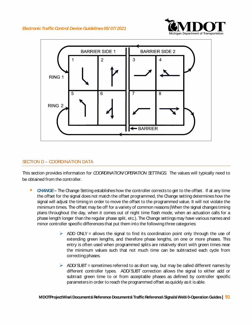
Electronic Traffic Control Device Guidelines 05/07/2021
MDOTProjectWise\Documents\Reference Documents\Traffic Reference\Signals\Web\0-Operation Guides | 91
SECTION D – COORDINATION DATA
This section provides information for COORDINATION/OPERATION SETTINGS. The values will typically need tobe obtained from the controller.
§ CHANGE – The Change Setting establishes how the controller corrects to get to the offset. If at any timethe offset for the signal does not match the offset programmed, the Change setting determines how thesignal will adjust the timing in order to move the offset to the programmed value. It will not violate theminimum times. The offset may be off for a variety of common reasons (When the signal changes timingplans throughout the day, when it comes out of night time flash mode, when an actuation calls for aphase length longer than the regular phase split, etc.). The Change settings may have various names andminor controller specific differences that put them into the following three categories:
Ø ADD ONLY = allows the signal to find its coordination point only through the use ofextending green lengths, and therefore phase lengths, on one or more phases. Thisentry is often used when programmed splits are relatively short with green times nearthe minimum values such that not much time can be subtracted each cycle fromcorrecting phases.
Ø ADD/SUBT = sometimes referred to as short way, but may be called different names bydifferent controller types. ADD/SUBT correction allows the signal to either add orsubtract green time to or from acceptable phases as defined by controller specificparameters in order to reach the programmed offset as quickly as it is able.

Electronic Traffic Control Device Guidelines 05/07/2021
MDOTProjectWise\Documents\Reference Documents\Traffic Reference\Signals\Web\0-Operation Guides | 92
Ø OTHR = use this entry if a Change setting not clearly identified by one of the explicitlylisted labels is used. Explain the setting in the Remarks Section.
§ REST IN WALK FOR COORD PHASE – This entry is applicable only for signals that are runningcoordinated. For intersections that are coordinated, the signal can dwell in WALK at the end of theWALK timing when there is no serviceable conflicting call. Enter “Y” for yes, coordinated phase will restin walk, meaning FDW will not come on until a conflicting call comes in. Enter “N” for no, coordinatedphase will not rest in walk, meaning there will be an automatic transition from walk; therefore, walkmust cycle or be actuated.
§ PUSHBUTTONS FOR COORD PHASE – This entry is applicable only for signals that are runningcoordinated. Enter “Y” for yes, pushbuttons are present for the coordinated phase. Enter “N” for no,pushbuttons are not present for the coordinated phase.
§ OTHER COORDINATION FIELDS – Default values need not be called out on the permit. Use for sitespecific settings (e.g. start of yellow offset, transition %, and slack time distribution). Describe settingsin the Remarks section on page 2 as needed.
7.1.37.1.37.1.3
7.1.3 SCHEDULING INFORMATION – NTCIP PERMIT
The Scheduling Information form (page 3) should accompany the signal timing permit form on all occasions.Figure 7-4 illustrates a sample Advanced Timing Parameters form. A description of each section (A – C) of theScheduling Information form and how to properly fill in these sections is provided in the text that follows.
Figure 7-4: Scheduling Information Form (NTCIP)
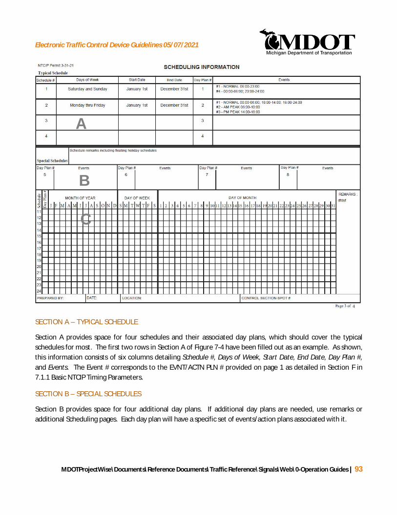
Electronic Traffic Control Device Guidelines 05/07/2021
MDOTProjectWise\Documents\Reference Documents\Traffic Reference\Signals\Web\0-Operation Guides | 93
SECTION A – TYPICAL SCHEDULE
Section A provides space for four schedules and their associated day plans, which should cover the typicalschedules for most. The first two rows in Section A of Figure 7-4 have been filled out as an example. As shown,this information consists of six columns detailing Schedule #, Days of Week, Start Date, End Date, Day Plan #,and Events. The Event # corresponds to the EVNT/ACTN PLN # provided on page 1 as detailed in Section F in7.1.1 Basic NTCIP Timing Parameters.
SECTION B – SPECIAL SCHEDULES
Section B provides space for four additional day plans. If additional day plans are needed, use remarks oradditional Scheduling pages. Each day plan will have a specific set of events/action plans associated with it.
A
B
C

Electronic Traffic Control Device Guidelines 05/07/2021
MDOTProjectWise\Documents\Reference Documents\Traffic Reference\Signals\Web\0-Operation Guides | 94
SECTION C – SPECIAL SCHEDULES GRID
Section C provides a grid that allows for identification of specific days of the month or days of each week withinany month. In the special schedule grid, next to the appropriate schedule number indicate the Day Plan to berun and X mark the months, days of the week, and specific days of the month that it may run. Day plans will notrun during any month, any day of the week, or any day of the month that is not checked. Day plans will befrequently associated with multiple schedules, either out of necessity or clarity of design intent. Schedulenumbers for special schedules start at 11 to avoid confusion between typical schedules and special schedules.
7.1.4 PREEMPTION INFORMATION FORM – NTCIP PERMIT
PREEMPTION INFORMATION is entered on page 3 of the timing permit (see Figure 7-5). This page only needs tobe included if preemption information exists. Four preemption plans may be entered on this form. If additionalpreemption plans are needed an additional sheet may be attached.
Figure 7-5: NTCIP Preemption Information Form
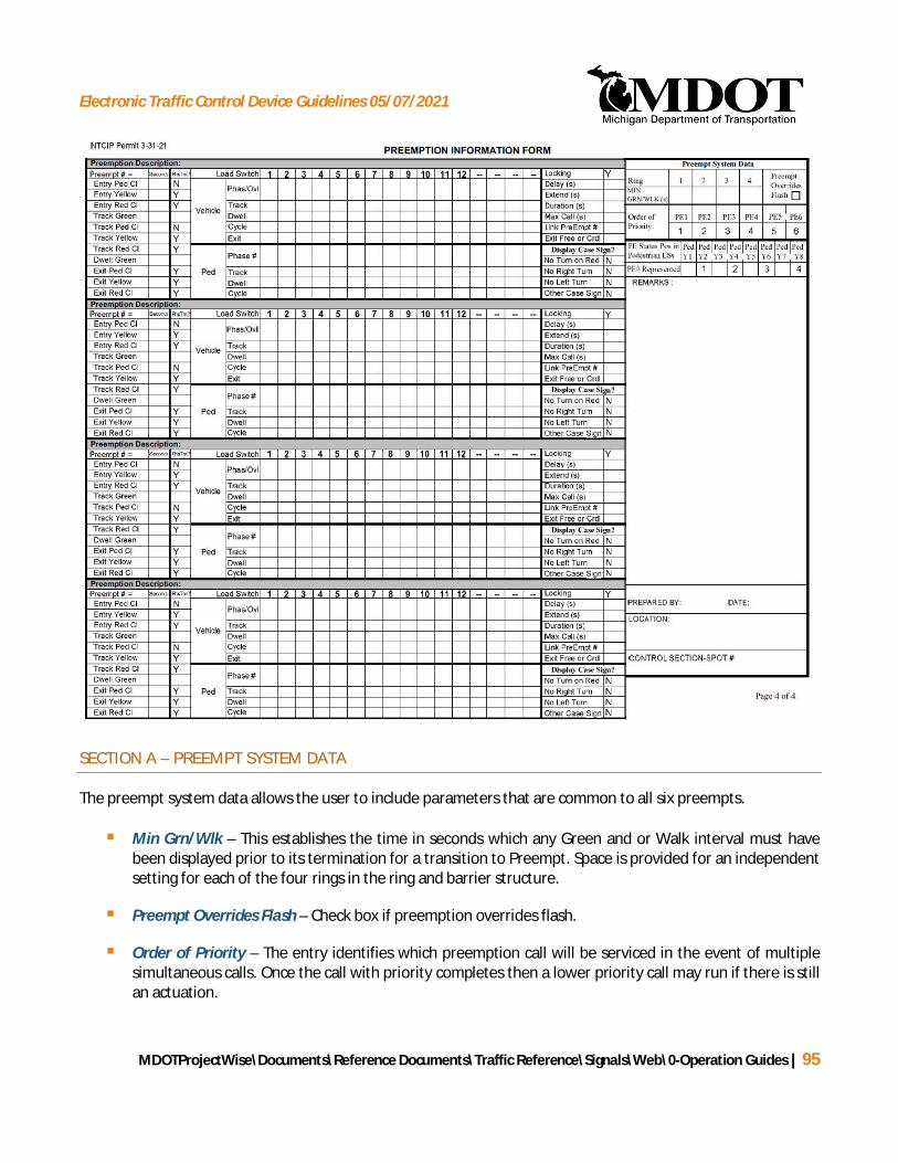
Electronic Traffic Control Device Guidelines 05/07/2021
MDOTProjectWise\Documents\Reference Documents\Traffic Reference\Signals\Web\0-Operation Guides | 95
SECTION A – PREEMPT SYSTEM DATA
The preempt system data allows the user to include parameters that are common to all six preempts.
§ Min Grn/Wlk – This establishes the time in seconds which any Green and or Walk interval must havebeen displayed prior to its termination for a transition to Preempt. Space is provided for an independentsetting for each of the four rings in the ring and barrier structure.
§ Preempt Overrides Flash – Check box if preemption overrides flash.
§ Order of Priority – The entry identifies which preemption call will be serviced in the event of multiplesimultaneous calls. Once the call with priority completes then a lower priority call may run if there is stillan actuation.

Electronic Traffic Control Device Guidelines 05/07/2021
MDOTProjectWise\Documents\Reference Documents\Traffic Reference\Signals\Web\0-Operation Guides | 96
§ PE Status Pos in Pedestrian LSs – The entry identifies where each preempt status light is located in thecabinet. These will be located in the otherwise unused yellow positions, typically in the phase 2,4,6, and8 pedestrian load switches. Default values place PE status 1, 2, 3, 4 in Pedestrian load switches 2, 4, 6,and 8
Section B – Preempt Times
§ Preemption Description – Enter a description of the preemption here.
§ Preempt Number - Indicate which of the 6 available preempts is being defined. If more than fourpreempt plans exist, then an additional form should be attached for the additional preempts.
§ Phase Time? (PhsTm?) - Identify whether the controller should use the phase times from pg 1.Electrician/Programmer should use these phase time values if possible when there is "Y" entry.
§ Entry Ped Cl – The Entry Ped clearance interval is provided to transition from a ped movement into apreempt. The proper pedestrian clearance time can be terminated early if necessary, by using the“Entry Ped Cl”. The type of preemption typically determines how much transition time is feasible.
Ø The MDOT project manager must be consulted prior to changing any of these values. Railroadsare required to provide a minimum amount of time prior to the train entering the intersection.Railroad preemption can be reduced as necessary to 1. If this minimum time is not sufficient,the required amount of time must be calculated and provided to the MDOT project managerand to the railroad.
Ø For emergency vehicle preemption, the Entry Ped Cl is typically set to the largest of the“Pedestrian Clearance” values from the various phases in operation. For example, at a two-phase signal where the normal pedestrian clearance is 12 seconds for one phase and 14 secondsfor the second phase, 14 seconds would be entered for the Entry Ped Cl as it is the larger of thetwo phases. The phase that it is transitioning to generally does not need to be considered unlessthere is a track green being utilized.
§ Entry Yellow, Entry Red Cl – The “Entry” clearance intervals are provided to transition from normaloperation into Track Green. Proper values for “Entry Yellow” and “Entry Red Cl” cannot be terminatedearly during this transition. The type of preemption typically determines how much transition time isfeasible. Railroad preemption will typically require minimal transition time. Emergency vehiclepreemption will typically allow for the full more transition time.
Ø For rail preemption, use the highest Yellow Clearance and All Red Clearance values from page 1phase information.
Ø For Emergency Vehicle preemption, use highest Yellow and Red Clearance values that are not ona phase that is being transition to.
Electronic Traffic Control Device Guidelines 05/07/2021
MDOTProjectWise\Documents\Reference Documents\Traffic Reference\Signals\Web\0-Operation Guides | 97
§ Track Green, Track Ped Cl, Track Yellow, Track Red Cl – The “Track” intervals are provided when arailroad track is located close to the intersection and they are intended to keep vehicles from queuingacross the track. The intervals provide a short period of green as well as clearance intervals at theintersection while the pre-signal at the tracks stays red. Doing this clears vehicles that were stopped onthe tracks while not allowing more vehicles on to the tracks. The “Track” intervals are typically usedwhen there are near and far signal heads at an intersection. The “Track” intervals clear vehiclesbetween the near and far signal head to avoid vehicle trapping.
Ø TRACK GREEN interval provides the time for the TRACK Green. If no time is entered for theTRACK Green interval, the “Track” intervals will be skipped (Track Green, Track Ped Clear, TrackYellow, and Track Red Clear).
· If the signal utilizes a flashing red ball for left turns, the track green must provide aminimum of 1.0 seconds in order to operate correctly.
Ø The TRACK Ped Clear interval is the time provided to clear a terminating Walk during thetransition to DWELL Green.
Ø The TRACK Yellow interval is the time provided to clear a terminating Green during thetransition to DWELL Green.
Ø The TRACK Red Clear interval is the time provided to clear a terminating Yellow during thetransition to DWELL Green.
§ Dwell Green, Exit Ped Cl, Exit Yellow, Exit Red Cl – The Dwell Green interval is the time that theintersection will dwell in green for the allowed phases during the preempt. The “Exit” clearanceintervals are provided to transition from preempt operation into normal operation. These values shouldbe set to the normal clearance intervals for the respective approach.
For railroad preempts the amount of fixed time the railroad gives the traffic signal prior to the trainentering the intersection is 20 seconds unless otherwise specified in writing from the railroad owner.Therefore, the sum of the Min Grn/Wlk, Entry Ped Cl, Entry Yellow, Entry Red Cl, and TRACK GREENtimes shall not typically exceed 20 seconds. In any cases where it is unclear whether the railroad ownerhas provided notices of a period less than 20 seconds, extreme caution should be exercised to makesure that a dangerous timing is not put in place. If there is an existing timing then the new time to clearthe tracks should not be increased without verification.
SECTION C – PREEMPT STATUS
§ Vehicle – Identify the Phase or Overlap that corresponds with each of the load switches in use. This isentered in the first Vehicle row and only needs to be done for one preempt as it auto populates theothers.
The vehicle signal head displays for the TRACK Green and DWELL Green for each phase are entered inthis area. Possible entries for these phases include:
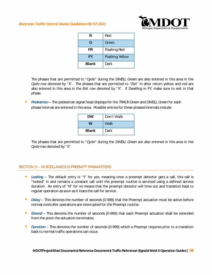
Electronic Traffic Control Device Guidelines 05/07/2021
MDOTProjectWise\Documents\Reference Documents\Traffic Reference\Signals\Web\0-Operation Guides | 98
R Red
G Green
FR Flashing Red
FY Flashing Yellow
Blank Dark
The phases that are permitted to “Cycle” during the DWELL Green are also entered in this area in theCycle row denoted by “X”. The phases that are permitted to “Exit” in after return yellow and red arealso entered in this area in the Exit row denoted by “X”. If Dwelling in FY, make sure to exit in thatphase.
§ Pedestrian – The pedestrian signal head displays for the TRACK Green and DWELL Green for eachphase/interval are entered in this area. Possible entries for these phases/intervals include:
DW Don’t Walk
W Walk
Blank Dark
The phases that are permitted to “Cycle” during the DWELL Green are also entered in this area in theCycle row denoted by “X”.
SECTION D – MISCELLANEOUS PREEMPT PARAMETERS
§ Locking – The default entry is “Y” for yes, meaning once a preempt detector gets a call, this call is“locked” in and remains a constant call until the preempt routine is serviced using a defined serviceduration. An entry of “N” for no means that the preempt detector will time out and transition back toregular operation as soon as it loses the call for service.
§ Delay – This denotes the number of seconds (0-999) that the Preempt actuation must be active beforenormal controller operations are interrupted for the Preempt routine.
§ Extend – This denotes the number of seconds (0-999) that each Preempt actuation shall be extendedfrom the point the actuation terminates.
§ Duration – This denotes the number of seconds (0-999) which a Preempt requires prior to a transitionback to normal traffic operations can occur.

Electronic Traffic Control Device Guidelines 05/07/2021
MDOTProjectWise\Documents\Reference Documents\Traffic Reference\Signals\Web\0-Operation Guides | 99
§ Max Call – This establishes the number of seconds (0-999) which a Preempt call may remain active andbe considered valid.
§ Link PreEmpt # – This establishes the higher priority Preempt routine which is to be linked to thisPreempt routine.
§ Exit Free or Crd – This identifies whether the initial transition out of the preemption is to free mode orcoordinated mode. This option may not be available on all controllers.
SECTION E –DISPLAY CASE SIGNS
Section E lists four types of Display Case Signs. The default value is “N” for each of the Display Case Signs,meaning the case sign is not provided. If the Display Case Sign is present, this value can be overridden with “Y”for yes. The following four types of Display Case Signs can be denoted in Section E:
Ø No Turn on Red – enter “Y” if No Turn on Red case sign is present.
Ø No Right Turn – enter “Y” if No Right Turn case sign is present.
Ø No Left Turn – enter “Y” if No Left Turn case sign is present.
Ø Other Case Sign – enter “Y” if other case sign is present. Describe in the REMARKS section onthe same page.
SECTION F – REMARKS & LOCATION
Section F provides space for REMARKS and general information about the signalized location. Any informationthat is necessary for the proper installation of the signal timing permit that was not captured by the fields of thesignal timing permit should be entered in this section. If all of the remarks do not fit into the space provided, donot change the font size as MDOT will lose all of this information in their database when the font is changed.
If a timing permit is prepared by a consultant, the consultant name should be included in the remarkssection. For example:
“OPTIMIZED BY (Insert Organization Name)”
The general information about the signalized location auto populates from the entries made on the first page.This information includes:
§ Who prepared the timing permit and the date
§ The location and control section-spot number

Electronic Traffic Control Device Guidelines 05/07/2021
MDOTProjectWise\Documents\Reference Documents\Traffic Reference\Signals\Web\0-Operation Guides | 100
7.2 EPAC CONTROLLER UNIT
The EPAC PERMIT is described below and in the EPAC TIMING PARAMETERS spreadsheet.
7.2.1 BASIC TIMING PARAMETERS FORM - EPAC CONTROLLER UNIT
The EPAC controller unit offers pre-timed, semi-actuated, and fully-actuated operation. Up to 16 phases in fourrings can be entered into the EPAC controller. illustrates a sample signal timing permit for an EPAC controllerunit. A description of each section (A – H) of the signal timing permit and how to properly complete eachsection is provided in the text that follows. All of the general information (1-5) is presented under Section 7.4Standard Information: Page 1. The ranges and increments for the timed values entered into the timing permitare provided in Table 7-11.
Figure 7-6: EPAC Timing Permit Example
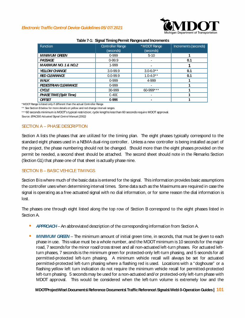
Electronic Traffic Control Device Guidelines 05/07/2021
MDOTProjectWise\Documents\Reference Documents\Traffic Reference\Signals\Web\0-Operation Guides | 101
Table 7-1: Signal Timing Permit Ranges and IncrementsFunction Controller Range
(seconds)*MDOT Range
(seconds)Increments (seconds)
MINIMUM GREEN 0-999 5-10 1PASSAGE 0-99.9 - 0.1MAXIMUM NO. 1 & NO.2 1-999 - 1YELLOW CHANGE 3.0-99.9 3.0-6.0** 0.1RED CLEARANCE 0.0-99.9 1.0-4.0** 0.1WALK 0-999 4-999 1PEDESTRIAN CLEARANCE 0-999 - 1CYCLE 30-999 60-999*** 1PHASE TIME (Split Time) 0-400 - 1OFFSET 0-999 - 1
*MDOT Range is listed only if different than the actual Controller Range** See Section B below for more details on yellow and red change interval ranges.***60 seconds minimum is MDOT’s typical restriction; cycle lengths less than 60 seconds require MDOT approval.Source: EPAC300 Actuated Signal Control Manual (2002)
SECTION A – PHASE DESCRIPTION
Section A lists the phases that are utilized for the timing plan. The eight phases typically correspond to thestandard eight phases used in a NEMA dual-ring controller. Unless a new controller is being installed as part ofthe project, the phase numbering should not be changed. Should more than the eight phases provided on thepermit be needed, a second sheet should be attached. The second sheet should note in the Remarks Section(Section G1) that phase one of that sheet is actually phase nine.
SECTION B – BASIC VEHICLE TIMINGS
Section B is where much of the basic data is entered for the signal. This information provides basic assumptionsthe controller uses when determining interval times. Some data such as the Maximums are required in case thesignal is operating as a free actuated signal with no dial information, or for some reason the dial information islost.
The phases one through eight listed along the top row of Section B correspond to the eight phases listed inSection A.
§ APPROACH – An abbreviated description of the corresponding information from Section A.
§ MINIMUM GREEN – The minimum amount of initial green time, in seconds, that must be given to eachphase in use. This value must be a whole number, and the MDOT minimum is 10 seconds for the majorroad, 7 seconds for the minor road/cross street and all non-actuated left-turn phases. For actuated left-turn phases, 7 seconds is the minimum green for protected-only left-turn phasing, and 5 seconds for allpermitted-protected left-turn phasing. A minimum vehicle recall will always be set for actuatedpermitted-protected left-turn phasing where a flashing red is used. Locations with a “doghouse” or aflashing yellow left turn indication do not require the minimum vehicle recall for permitted-protectedleft-turn phasing. 5 seconds may be used for a non-actuated and/or protected-only left-turn phase withMDOT approval. This would be considered when the left-turn volume is extremely low and the

Electronic Traffic Control Device Guidelines 05/07/2021
MDOTProjectWise\Documents\Reference Documents\Traffic Reference\Signals\Web\0-Operation Guides | 102
additional 2 seconds taken from the left-turn would provide a significant benefit to the other phases ofthe signal.
§ PASSAGE – The extended portion of the green time for an actuated approach is a function of vehicleactuations that occur after the minimum green is served. The phase remains green after the minimumgreen has been served until no additional calls are received and the passage timer has timed out, oruntil the maximum green time is reached. The passage timer is reset with each subsequent vehicleactuation and begins timing again when the actuation is removed. The typical passage time is 3.0seconds.
o While uncommon, it is possible for an actuated phase to have a passage time equal to zero. Thisis sometime used where there are multiple lanes of detection for an approach or a particularlylong detection zone. Unusual operations such as this should be noted in the remarks section.
§ MAXIMUM NO. 1 – The maximum length of time this phase may be held green in the presence of aserviceable conflicting call. In the absence of a serviceable conflicting call, the maximum green timer isheld reset. The value is to be entered in whole seconds and typically matches the highest split enteredin Section F for that particular phase.
§ MAXIMUM NO. 2 – This time setting serves the same function as MAXIMUM NO. 1. This is mostcommonly used at intersections that run free where the volumes change significantly over the course ofa day and require different maximum times at different times of the day. To achieve this, MAXIMUMNO. 2 can be designated to run at certain times of the day.
o There are 3 additional Maximum times available, but they are very rarely used as they requirespecial programming techniques in the controller. The MAXIMUM NO.2 data is typically leftwith a default value of zero entered.
§ YELLOW CHANGE – The yellow change interval time for each phase. The value is entered in seconds in0.1 second increments. Per MDOT policy, the yellow change interval must be at least 3.0 seconds. Thetypical range is 3.0 to 6.0 seconds. Yellow change intervals greater than 6.0 seconds may be used withMDOT approval.
§ RED CLEARANCE – The all-red clearance interval time for each phase. The value is entered in seconds in0.1 second increments. Per MDOT policy, the red clearance interval must be at least 1.0 second. Thetypical range is from 1.5 to 4.0 seconds. Red clearance intervals greater than 4.0 seconds may be usedwith MDOT approval. Situations that may require longer all red times include locations with a trailgreen, single-point urban interchanges, and diverging diamond interchanges.
SECTION C – PEDESTRIAN TIMING
Pedestrian timing data is entered in Section C. The WALK time, PEDESTRIAN CLEARANCE time, EXTENDEDPEDESTRIAN CLEARANCE code, and REST IN WALK code are entered here for each phase.
§ WALK – The minimum time, in seconds, that the walk display must be displayed for this phase. Thevalue must be entered in whole seconds. Per MDOT policy, the typical minimum WALK time is 7.0
Electronic Traffic Control Device Guidelines 05/07/2021
MDOTProjectWise\Documents\Reference Documents\Traffic Reference\Signals\Web\0-Operation Guides | 103
seconds. A minimum WALK time of 4.0 seconds may be used, where deemed appropriate based onpedestrian characteristics, volumes, and timing requirements, with approval of MDOT. In somesituations, the minimum walk time will be greater than 7.0 seconds (see Section 4.3.2)
§ PEDESTRIAN CLEARANCE – The time in seconds that the “Flash Don’t Walk” indication, is displayedduring each phase. This value must be entered in whole seconds. This is different from the calculatedpedestrian clearance which includes a buffer interval after the Flash Don’t Walk.
§ EXTENDED PED. CLEARANCE – Defines when the Flash Don’t Walk indication terminates. The codes arefound in Table 7-22. Code 0 is most typically required to meet the 3 s minimum buffer requirement. Ifthe All-Red time is 3 s or greater, then code 2 may be used (Note that MOD 10 controllers and older donot have the code 2 option). If the controller has the option to terminate the Flash Don’t Walk atexactly 3 s before the end of All-Red, then this is the preferred option.
§ REST IN WALK – This entry is applicable only for signals that are running uncoordinated. For signalsrunning in coordinated mode, this entry is overridden by the coordination mode (see section 7.5 E). Forintersections that are actuated and uncoordinated, the signal can dwell in DON’T WALK (Mode 0) orWALK (Mode 1) at the end of the WALK timing when there is no serviceable conflicting call. If there is apedestrian push-button available, having the signal dwell in DON’T WALK is preferable as it cantransition to a conflicting phase more quickly if a call comes in. If there is not a pedestrian push button,the signal should be set up to dwell in WALK with locking side street vehicle detection. Otherwise, ifthere are no conflicting calls, the signal will continue to dwell in DON’T WALK and a pedestrian will neverhave an opportunity to cross. It is preferred that logic common be jumpered to the walk rest modifierinput on the controller back panel. Then set ped recall to code 3 which is "non-actuated". This allowswalk cycling to occur when side street vehicle detection is non-locking. This will override the entry forrest in walk.
Table 7-2: Extended Pedestrian Clearance Codes and Descriptions
Code Description0 (Normal) Flash Don’t Walk ends at the end of Green1 (Extended Ped. Clear)* Flash Don’t Walk ends at the end of All-Red2 (Extended Ped. Clear) Flash Don’t Walk ends at the end of Yellow
*Extended Pedestrian Clearance code 1 is no longer acceptable if it does not allow the minimum 3 second pedestrian clearance buffer interval requiredper the MMUTCD.Source: EPAC300 Actuated Signal Control Manual (2002)
SECTION D – INITIALIZATION AND ACTUATION
This section contains the information for INITIALIZATION, NON-ACT RESPONSE, VEHICLE RECALL, andPEDESTRIAN RECALL.
§ INITIALIZATION – INITIALIZATION occurs when there is a restoration of power after a defined powerinterruption, or the activation of External Start input is entered. An entry for INITIALIZATION is providedto cause the controller unit to start at the beginning of the Green, Yellow, or Red interval of any phaseor non-conflicting phase pair. The INITIALIZATION codes are shown in Table 7-33. The typical valuesused are 4 for the major movement and 1 for the minor movements.
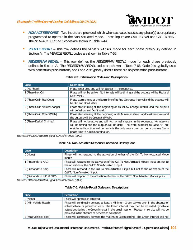
Electronic Traffic Control Device Guidelines 05/07/2021
MDOTProjectWise\Documents\Reference Documents\Traffic Reference\Signals\Web\0-Operation Guides | 104
§ NON-ACT RESPONSE – Two inputs are provided which when activated causes any phase(s) appropriatelyprogrammed to operate in the Non-Actuated Mode. These inputs are CALL TO NAI and CALL TO NAII.The NON-ACT RESPONSE codes are shown in Table 7-44.
§ VEHICLE RECALL – This row defines the VEHICLE RECALL mode for each phase previously defined inSection A. The VEHICLE RECALL codes are shown in Table 7-55.
§ PEDESTRIAN RECALL – This row defines the PEDESTRIAN RECALL mode for each phase previouslydefined in Section A. The PEDESTRIAN RECALL codes are shown in Table 7-66. Code 0 is typically usedwith pedestrian push-buttons, and Code 2 is typically used if there are no pedestrian push-buttons.
Table 7-3: Initialization Codes and Descriptions
Code Description0 (No Phase) Phase is not used and will not appear in the sequence.1 (Phase Not On) Phase will not be active. No intervals will be timing and the outputs will be Red and
Don’t Walk.2 (Phase On in Red Clear) Phase starts timing at the beginning of its Red Clearance interval and the outputs will
be Red and Don’t Walk.3 (Phase On in Yellow Change) Phase starts timing at the beginning of its Yellow Change interval and the outputs
will be Yellow and Don’t Walk.4 (Phase On in Green/Walk) Phase starts timing at the beginning of its Minimum Green and Walk intervals and
the outputs will be Green and Walk.5 (Phase Dark & Omitted) Phase will not be active and will not normally appear in the sequence. No intervals
will be timing and the outputs will be dark. The state is similar to Code “0” butenables a distinction and currently is the only way a user can get a dummy (dark)phase time to run in Coordination.
Source: EPAC300 Actuated Signal Control Manual (2002)
Table 7-4: Non-Actuated Response Codes and Descriptions
Code Description0 (None) Phase will not respond to the activation of either of the Call To Non-Actuated Mode
inputs.1 (Responds to NA1) Phase will respond to the activation of the Call To Non-Actuated Mode I input but not to
the activation of the Call To Non-Actuated II input.2 (Responds to NA2) Phase will respond to the Call To Non-Actuated II input but not to the activation of the
Call To Non-Actuated I input.3 (Responds to NA1 & NA2) Phase will respond to the activation of either of the Call To Non-Actuated Mode inputs.
Source: EPAC300 Actuated Signal Control Manual (2002)
Table 7-5: Vehicle Recall Codes and Descriptions
Code Description0 (None) Phase will operate as actuated.2 (Min Vehicle Recall) Phase will continually demand at least a Minimum Green service even in the absence of
actual vehicle or pedestrian calls. The Green interval may then be extended by vehicleactuations during the Green interval in the usual manner. Pedestrian service will not beprovided in the absence of pedestrian actuations.
3 (Max Vehicle Recall) Phase will continually demand the Maximum Green setting. The Green interval will not
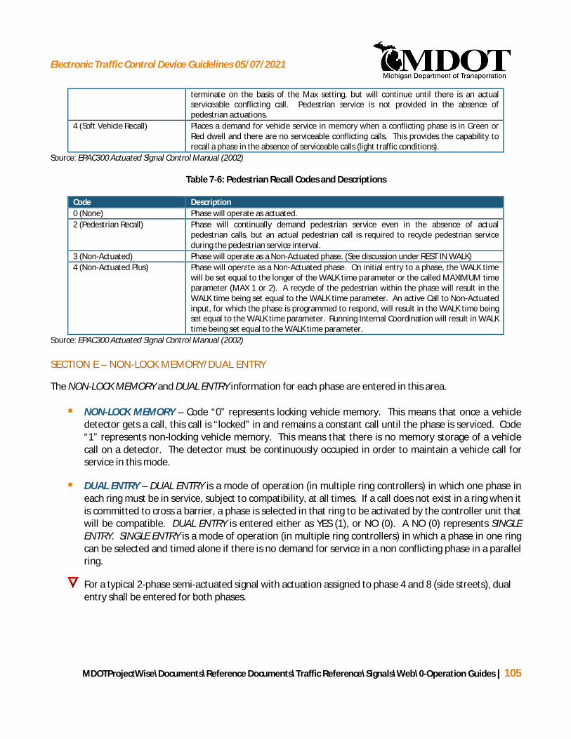
Electronic Traffic Control Device Guidelines 05/07/2021
MDOTProjectWise\Documents\Reference Documents\Traffic Reference\Signals\Web\0-Operation Guides | 105
terminate on the basis of the Max setting, but will continue until there is an actualserviceable conflicting call. Pedestrian service is not provided in the absence ofpedestrian actuations.
4 (Soft Vehicle Recall) Places a demand for vehicle service in memory when a conflicting phase is in Green orRed dwell and there are no serviceable conflicting calls. This provides the capability torecall a phase in the absence of serviceable calls (light traffic conditions).
Source: EPAC300 Actuated Signal Control Manual (2002)
Table 7-6: Pedestrian Recall Codes and Descriptions
Code Description0 (None) Phase will operate as actuated.2 (Pedestrian Recall) Phase will continually demand pedestrian service even in the absence of actual
pedestrian calls, but an actual pedestrian call is required to recycle pedestrian serviceduring the pedestrian service interval.
3 (Non-Actuated) Phase will operate as a Non-Actuated phase. (See discussion under REST IN WALK)4 (Non-Actuated Plus) Phase will operate as a Non-Actuated phase. On initial entry to a phase, the WALK time
will be set equal to the longer of the WALK time parameter or the called MAXIMUM timeparameter (MAX 1 or 2). A recycle of the pedestrian within the phase will result in theWALK time being set equal to the WALK time parameter. An active Call to Non-Actuatedinput, for which the phase is programmed to respond, will result in the WALK time beingset equal to the WALK time parameter. Running Internal Coordination will result in WALKtime being set equal to the WALK time parameter.
Source: EPAC300 Actuated Signal Control Manual (2002)
SECTION E – NON-LOCK MEMORY/DUAL ENTRY
The NON-LOCK MEMORY and DUAL ENTRY information for each phase are entered in this area.
§ NON-LOCK MEMORY – Code “0” represents locking vehicle memory. This means that once a vehicledetector gets a call, this call is “locked” in and remains a constant call until the phase is serviced. Code“1” represents non-locking vehicle memory. This means that there is no memory storage of a vehiclecall on a detector. The detector must be continuously occupied in order to maintain a vehicle call forservice in this mode.
§ DUAL ENTRY – DUAL ENTRY is a mode of operation (in multiple ring controllers) in which one phase ineach ring must be in service, subject to compatibility, at all times. If a call does not exist in a ring when itis committed to cross a barrier, a phase is selected in that ring to be activated by the controller unit thatwill be compatible. DUAL ENTRY is entered either as YES (1), or NO (0). A NO (0) represents SINGLEENTRY. SINGLE ENTRY is a mode of operation (in multiple ring controllers) in which a phase in one ringcan be selected and timed alone if there is no demand for service in a non conflicting phase in a parallelring.
For a typical 2-phase semi-actuated signal with actuation assigned to phase 4 and 8 (side streets), dualentry shall be entered for both phases.

Electronic Traffic Control Device Guidelines 05/07/2021
MDOTProjectWise\Documents\Reference Documents\Traffic Reference\Signals\Web\0-Operation Guides | 106
SECTION F – DIAL-SPLIT SET-UP
Section F is the Dial-Split data section. It establishes the cycle lengths, splits, offsets, and actuation modes forthe Dial-Split Combinations if a defined cycle length is being used. Dial and split information is entered in theleft most box of Section F. There are four dials (1-4) and each dial has four splits (1-4) available for a total of 16Dial-Split Combinations. Each Dial-Split Combination can have up to 3 offsets. Under typical conditions, MDOT’sstandard convention is to use Dial 1 Split 1 Offset 1 for normal “off-peak” operation, Dial 2 Split 1 Offset 1 forthe AM peak period, and Dial 3 Split 1 Offset 1 for the PM peak period. However, assignment of dials may varydepending on maintaining agency and should therefore be determined in advance of preparing a timing permit.If needed, additional dial and split information can be entered on page 2 (see Section 7.2.2).
§ CYCLE – The cycle length, in seconds, for each dial in operation.
§ PHASE TIME – The phase time for each phase is entered for each dial in operation. The phase timeincludes the green time, yellow time, and all-red time for that phase. Phase time data supersedes thevalues entered in MAXIMUM NO.1 and NO.2. The Phase Times are often referred to as Splits.
§ OFFSETS – The offsets for each dial in operation are entered, in seconds, in the last three columns ofSection F. Up to three offsets may be entered for each dial split.
Ø If the offset is set to the cycle length, the Phase Time values become maximum greentimes with the yellow and all red times being timed separately. In addition thecontroller unit will be running free (un-coordinated). But the splits entered cannotviolate the minimum split time. This can be problematic with short left turn phases.
§ MODE – This row represents the Phase Mode for each respective phase defined in Section A. The phasemode combines with the VEHICLE and PEDESTRIAN RECALL codes entered in Section E. The codesrepresenting the different Phase Modes are shown in Table 7-77. The controller is capable of havingdifferent Mode settings for each Dial-Split combination, but typically the mode will be the same for alltime periods. The trunkline through movement will typically be set as the coordinated phase.
Ø For consistency, if the controller is running fixed time, set the side road mode to dualcoordination (code = 7).
Ø Dual coordination should not be used with actuated operations unless the intent is toprovide coordination for the crossroad in addition to the trunkline.
For information on minimum split times see Section 4.3.
Table 7-7: Phase Mode Codes and Descriptions
Code Description0 (Actuated) Phase will operate as actuated.1 (Coordinated Phase) Phase will operate as the Coordinated Phase for the ring.2 (Minimum Recall) Phase will operate as an actuated phase with a Minimum Recall.3 (Maximum Recall) Phase will operate as an actuated phase with a Maximum Recall.
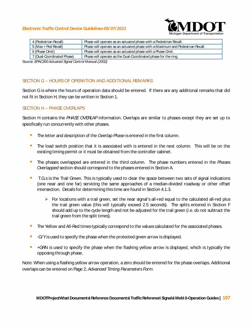
Electronic Traffic Control Device Guidelines 05/07/2021
MDOTProjectWise\Documents\Reference Documents\Traffic Reference\Signals\Web\0-Operation Guides | 107
4 (Pedestrian Recall) Phase will operate as an actuated phase with a Pedestrian Recall.5 (Max + Ped Recall) Phase will operate as an actuated phase with a Maximum and Pedestrian Recall.6 (Phase Omit) Phase will operate as an actuated phase with a Phase Omit.7 (Dual-Coordinated Phase) Phase will operate as the Dual-Coordinated phase for the ring.
Source: EPAC300 Actuated Signal Control Manual (2002)
SECTION G – HOURS OF OPERATION AND ADDITIONAL REMARKS
Section G is where the hours of operation data should be entered. If there are any additional remarks that didnot fit in Section H, they can be written in Section 1.
SECTION H – PHASE OVERLAPS
Section H contains the PHASE OVERLAP information. Overlaps are similar to phases except they are set up tospecifically run concurrently with other phases.
§ The letter and description of the Overlap Phase is entered in the first column.
§ The load switch position that it is associated with is entered in the next column. This will be on theexisting timing permit or it must be obtained from the controller cabinet.
§ The phases overlapped are entered in the third column. The phase numbers entered in the PhasesOverlapped section should correspond to the phases entered in Section A.
§ T.G.s is the Trail Green. This is typically used to clear the space between two sets of signal indications(one near and one far) servicing the same approaches of a median-divided roadway or other offsetintersection. Details for determining this time are found in Section 4.1.3.
Ø For locations with a trail green, set the near signal’s all-red equal to the calculated all-red plusthe trail green value (this will typically exceed 2.5 seconds). The splits entered in Section Fshould add up to the cycle length and not be adjusted for the trail green (i.e. do not subtract thetrail green from the split times).
§ The Yellow and All-Red times typically correspond to the values calculated for the associated phases.
§ -G/Y is used to specify the phase when the protected green arrow is displayed.
§ +GRN is used to specify the phase when the flashing yellow arrow is displayed, which is typically theopposing through phase.
Note: When using a flashing yellow arrow operation, a zero should be entered for the phase overlaps. Additionaloverlaps can be entered on Page 2, Advanced Timing Parameters Form.
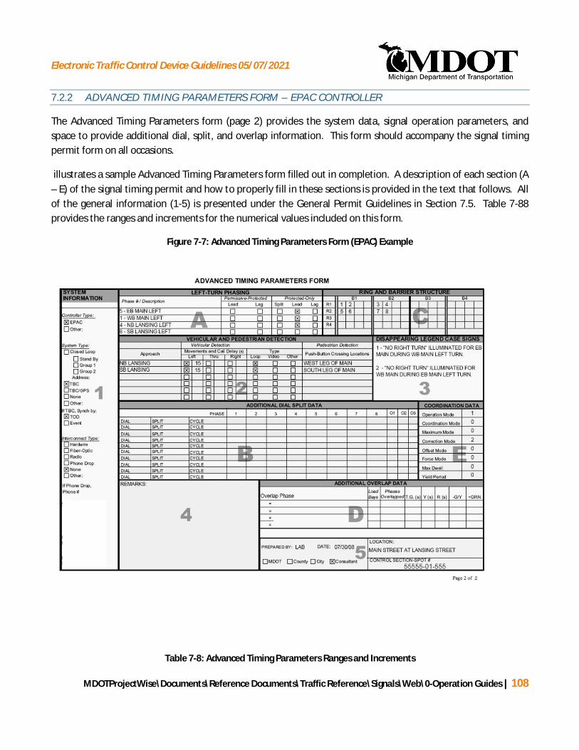
Electronic Traffic Control Device Guidelines 05/07/2021
MDOTProjectWise\Documents\Reference Documents\Traffic Reference\Signals\Web\0-Operation Guides | 108
7.2.2 ADVANCED TIMING PARAMETERS FORM – EPAC CONTROLLER
The Advanced Timing Parameters form (page 2) provides the system data, signal operation parameters, andspace to provide additional dial, split, and overlap information. This form should accompany the signal timingpermit form on all occasions.
illustrates a sample Advanced Timing Parameters form filled out in completion. A description of each section (A– E) of the signal timing permit and how to properly fill in these sections is provided in the text that follows. Allof the general information (1-5) is presented under the General Permit Guidelines in Section 7.5. Table 7-88provides the ranges and increments for the numerical values included on this form.
Figure 7-7: Advanced Timing Parameters Form (EPAC) Example
Table 7-8: Advanced Timing Parameters Ranges and Increments

Electronic Traffic Control Device Guidelines 05/07/2021
MDOTProjectWise\Documents\Reference Documents\Traffic Reference\Signals\Web\0-Operation Guides | 109
Function Controller Range(seconds)
*MDOT Range(seconds)
Increments(seconds)
Phase Overlap Trail Green 0-99.9 - 0.1Phase Overlap Yellow 3.0-99.9 3.0-6.0** 0.1Phase Overlap Red 0-99.9 1.0-4.0** 0.1Call Delay (Vehicular Detection) 0-999 - 1Max Dwell 0-999 - 1Yield Period 0-999 - 1
*MDOT Range is listed only if different than the actual Controller Range**See 4.1, for details on yellow and red clearance intervals.Source: EPAC300 Actuated Signal Control Manual (2002)
SECTION A – LEFT-TURN PHASING
The LEFT-TURN PHASING information is entered in Section A. The left-turn Phase # / Phase Descriptioninformation as well as Permissive-Protected and Protected Only information are entered in this section.
§ Phase # / Phase Description – The left-turn phase number, followed by a description of the phase areentered in this area. This information must match the left-turn information found in Section A of theBasic Timing Parameters Form for EPAC Controllers.
§ Permissive-Protected and Protected-Only Phasing – In this section, the left-turn operation should bedefined as either a “leading,” “lagging,” or “split” phase (relative to the parallel through movement), andwhether permissive left-turns are allowed during the companion through phase. Only one box shouldbe checked for each phase.
Ø Note: If a lagging left-turn phase is selected, the electrician will input an “alt sequence” into thecontroller. Do not reverse the phase sequence in the Ring and Barrier Structure if lagging leftturn phase has already been selected
SECTION B – ADDITIONAL DIAL SPLIT DATA
Additional Dial Split Data may be entered on page 2. Refer to Section 1.1 (Section F) of the EPAC Basic TimingParameters Form for more detail.
SECTION C – RING AND BARRIER STRUCTURE
The RING and BARRIER STRUCTURE entered in Section C defines and illustrates the phase operations of acontroller.
§ A Ring is a series of conflicting phases that occur in an established order and never at the same time.
§ A Barrier is a compatibility line in the sequence of a multi-ring controller that interlocks the Rings. ABarrier assures there will be no concurrent selection and timing of conflicting phases for trafficmovements in different Rings. All Rings cross the barrier simultaneously to select and time phases onthe other side.

Electronic Traffic Control Device Guidelines 05/07/2021
MDOTProjectWise\Documents\Reference Documents\Traffic Reference\Signals\Web\0-Operation Guides | 110
Section C is set up with four Barriers and four Rings (the current constraints of an EPAC controller). The phasenumbers should be entered in their corresponding areas and match the phases identified in Section A of theBasic Timing Parameters Form for EPAC Controllers.
Typically, an eight-phase dual-ring controller is utilized in the field. illustrates this controller configurationbased on the National Electrical Manufacturers Association (NEMA) standard, which is as follows:
§ Phases 2 and 6 are the main street through movements
§ Phases 1 and 5 are the main street left-turn movements
§ Phases 4 and 8 are the minor street through movements
§ Phases 3 and 7 are the minor street left-turn movements
Four boxes are provided in each Ring per Barrier for more complicated and non-standard phasing schemes, suchas split-phasing or sequential phasing.
When filling out the Advanced Timing Parameters Form for new signal installations, the NEMA standard shouldbe adhered to whenever possible when filling out the ring and barrier structure
Figure 7-8: Dual-Ring Controller (NEMA Standard)

Electronic Traffic Control Device Guidelines 05/07/2021
MDOTProjectWise\Documents\Reference Documents\Traffic Reference\Signals\Web\0-Operation Guides | 111
SECTION D – PHASE OVERLAPS
See Section 1.1 Section H of the EPAC Basic Timing Parameters form for more details.
SECTION E – COORDINATION DATA
This section provides information for OPERATION MODE, COORDINATION MODE, MAXIMUM MODE,CORRECTION MODE, OFFSET MODE, FORCE MODE, MAX DWELL, and YIELD PERIOD. The values will typicallyneed to be obtained from the controller.
§ Operation Mode – The Operation Mode establishes whether the signal operates as Free or Coordinated.
Ø 0 - provides Non-Coordinated (Free) operation. This is the typical setting for signals that arenot coordinated and are not locked down to a particular cycle length.
· If the signal is Non-coordinated and is running Max 1 and Max 2 timesdepending on the time of day it is suggested that if the signal is running free, fillin all zeros for the Operation Mode. If the signal is running dial/splits part of theday and free the remainder, fill in the Operation Mode based on the dial/splitoperation.
Ø 1 - Provides for Coordination operation to be automatically determined by interconnect,time base, or system commands. This is the typical setting for a coordinated system.
Ø 2 - Provides for Manual Coordination operation. This option allows for a singledial/split/offset combination to run always. This is not typically used as a permanentsetting.
§ Coordination Mode – The Coordination Mode establishes the type of coordination. The followingprovides descriptions of each mode. See Table 7-99 for codes and brief descriptions.
Ø 0 = Permissive (Typical Value): Under permissive coordination the controller will transitionto the coordinated phase(s), and upon completion of the coordinated phase(s) split timerest in the Green/Don’t Walk state,. Because the controller is already in a state (Green/DW)where it can readily exit the coordinated phase(s), this allows a relatively large time windowto transition from the coordinated phase(s) to the actuated non-coordinated phase(s). Afterthe transition time window closes, and there is no call placed from the non-coordinatedphase(s), the controller will cycle back to Green/Walk for the coordinated phase(s). Whenmultiple non-coordinated phases are present, the coordinator provides sequential releases,based on the order of the ring structure, to the non-coordinated phases
Ø 1 = Yield: Under yield coordination the controller will rest in the Green/Walk state if there isan absence of call from the actuated non-coordinated phases. This allows a relatively shorttime window to transition from the coordinated phase(s) to the actuated non-coordinatedphase(s), potentially increasing the worst case delay time to service non-coordinated

Electronic Traffic Control Device Guidelines 05/07/2021
MDOTProjectWise\Documents\Reference Documents\Traffic Reference\Signals\Web\0-Operation Guides | 112
actuated phases. When multiple non-coordinated phases are present, the coordinatorprovides a single release to the non-coordinated phases.
Ø 2 = Permissive Yield: Permissive Yield is similar to Permissive mode except for thecoordinated phase(s) pedestrian movement(s) are actuated. This mode is useful whenpedestrian push buttons are provided for the coordinated phase(s).
Ø 3 = Permissive Omit: Permissive Omit is similar to Permissive Yield except for onceterminated, the coordinated phase(s) are omitted. This prevents the controller from exitingthe non-coordinated phase(s) early to return to the coordinated phase(s).
Ø 4 = Sequential Omit: Sequential Omit is similar to the Permissive Yield mode except itprovides a phase by phase sliding window of service (omit lifted), resulting in one and onlyone phase in a ring having the omit lifted at any time.
Ø 5=Fully Actuated: Fully Actuated coordinated is similar to Permissive mode except for thecoordinated phase(s) will act as an actuated phase. This is useful if vehicle detection is usedon the coordinated phase(s).
Table 7-9: Coordination Mode Codes and Descriptions
Code Description0 (Permissive) Provides Permissive Coordination operation (typical value)1 (Yield) Provides Yield Coordination operation2 (Permissive Yield) Provides Permissive Yield Coordination (use if push buttons for coordinated phase
pedestrian signals are present)3 (Permissive Omit) Provides Permissive Omit Coordination operation4 (Sequential Omit) Provides Sequential Omit Coordination operation5 (Fully Actuated) Provides Full Actuated Coordination operation
EPAC300 Actuated Signal Control Manual (2002)
Example of Permissive and Yield coordination modes:
Assumptions:
§ Assume a two-phase semi-actuated signal.
§ Coordinated phase: 30 second split, 7 second walk, 20 second APCT*, 5 second yellow & all red
§ Actuated phase: 30 second split 7 second walk, 20 second APCT*, 5 second yellow & all red
*APCT is actual pedestrian clearance time which consists of the FDW time plus the Steady Don’t Walk BufferInterval (BI).
When a call arrives, will the actuated phase be serviced (times are from start of coordinated green)?
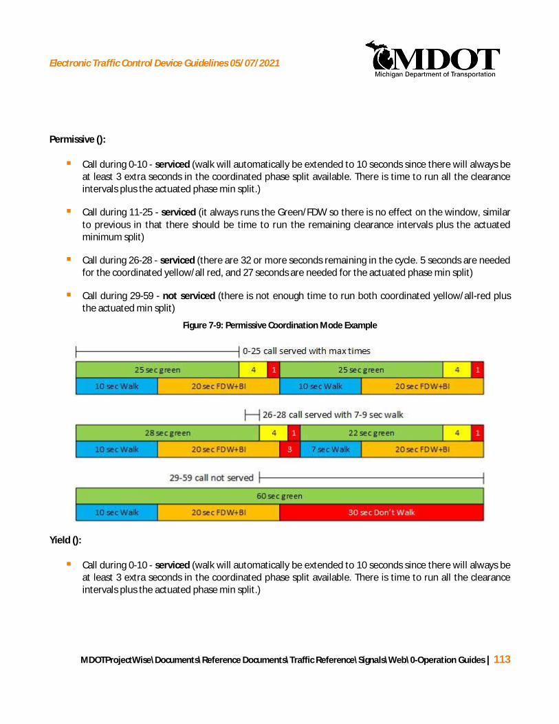
Electronic Traffic Control Device Guidelines 05/07/2021
MDOTProjectWise\Documents\Reference Documents\Traffic Reference\Signals\Web\0-Operation Guides | 113
Permissive ():
§ Call during 0-10 - serviced (walk will automatically be extended to 10 seconds since there will always beat least 3 extra seconds in the coordinated phase split available. There is time to run all the clearanceintervals plus the actuated phase min split.)
§ Call during 11-25 - serviced (it always runs the Green/FDW so there is no effect on the window, similarto previous in that there should be time to run the remaining clearance intervals plus the actuatedminimum split)
§ Call during 26-28 - serviced (there are 32 or more seconds remaining in the cycle. 5 seconds are neededfor the coordinated yellow/all red, and 27 seconds are needed for the actuated phase min split)
§ Call during 29-59 - not serviced (there is not enough time to run both coordinated yellow/all-red plusthe actuated min split)
Figure 7-9: Permissive Coordination Mode Example
Yield ():
§ Call during 0-10 - serviced (walk will automatically be extended to 10 seconds since there will always beat least 3 extra seconds in the coordinated phase split available. There is time to run all the clearanceintervals plus the actuated phase min split.)
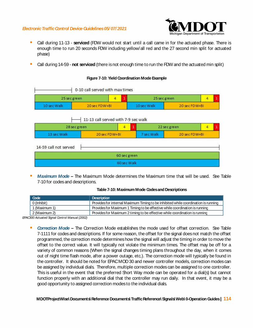
Electronic Traffic Control Device Guidelines 05/07/2021
MDOTProjectWise\Documents\Reference Documents\Traffic Reference\Signals\Web\0-Operation Guides | 114
§ Call during 11-13 - serviced (FDW would not start until a call came in for the actuated phase. There isenough time to run 20 seconds FDW including yellow/all red and the 27 second min split for actuatedphase)
§ Call during 14-59 - not serviced (there is not enough time to run the FDW and the actuated min split)
Figure 7-10: Yield Coordination Mode Example
§ Maximum Mode – The Maximum Mode determines the Maximum time that will be used. See Table7-10 for codes and descriptions.
Table 7-10: Maximum Mode Codes and Descriptions
Code Description0 (Inhibit) Provides for internal Maximum Timing to be inhibited while coordination is running1 (Maximum 1) Provides for Maximum 1 Timing to be effective while coordination is running2 (Maximum 2) Provides for Maximum 2 timing to be effective while coordination is running
EPAC300 Actuated Signal Control Manual (2002)
§ Correction Mode – The Correction Mode establishes the mode used for offset correction. See Table7-1111 for codes and descriptions. If for some reason, the offset for the signal does not match the offsetprogrammed, the correction mode determines how the signal will adjust the timing in order to move theoffset to the correct value. It will typically not violate the minimum times. The offset may be off for avariety of common reasons (When the signal changes timing plans throughout the day, when it comesout of night time flash mode, after a power outage, etc.). The correction mode will typically be found inthe controller. It should be noted for EPAC MOD 30 and newer controller models, correction modes canbe assigned by individual dials. Therefore, multiple correction modes can be assigned to one controller.This is useful in the event that the preferred Short Way mode can be operated for a dial(s) but cannotfunction properly with an additional dial that the controller may run daily. In that event, it may be agood opportunity to assigned correction modes to the individual dials.

Electronic Traffic Control Device Guidelines 05/07/2021
MDOTProjectWise\Documents\Reference Documents\Traffic Reference\Signals\Web\0-Operation Guides | 115
Ø 0 – Dwell: causes the signal to dwell in green interval beyond the time defined for the phaseuntil the correction has been accomplished. This correction mode is not typically used.Especially at locations with high cycle lengths, it can cause the signal to dwell in one phase for aninordinate length of time.
Ø 1 – Max Dwell: causes the signal to dwell in the same manner as Dwell, but limits the maximumamount of time the signal can dwell per cycle. If the correction cannot be completed in onecycle, the signal will continue to correct in future cycles until the offset is correct. If they cyclelength is 90 seconds or less, Max Dwell may be a good alternative to Short Way +.
Ø 2 – Short Way: allows the signal to dwell or if it can correct the offset faster by reducing thetime provided for the phases, it will do that. Correction will not exceed 19% in a cycle and willautomatically take into consideration minimum times.
· With Short Way correction, it is important that the phasing have enough time beyondthe minimum times to allow for a reduction in the split time. If this is not accounted for,it is possible for the signal to get caught in an endless loop as it tries to subtract timefrom a phase and the minimum times don’t allow for it. If this happens, the signal willnever be able to correct the offset.
· The requirement to use Short Way is that the sum of the difference between the phasesplit times and the respective phase minimum split times must exceed at least 19% ofthe cycle length.
· If the Short Way method does not meet the requirements stated above, consider ShortWay + or Max Dwell Mode.
Ø 3 – Short Way+: this correction mode is identical to Max Dwell except correction will not exceed20% in a cycle. This mode does not reduce interval times to adjust the offset.
· If a larger Max Dwell time is entered, it will override the 20% default value. To avoidconfusion, if a maximum dwell time other than 20% of the cycle length is desired, useMax Dwell as the correction type. With Short Way+, the Max Dwell should be set tozero.
· Short Way is the preferred method, but as mentioned above it requires splits beyondwhat is required for the minimum times.
· If the intersection contains push buttons this may also affect the decision betweenShort Way and Short Way+.
o The difference between the proposed splits and the minimum times should belooked at to see how much time can be subtracted from the split times (keepingin mind the 20% maximum correction per cycle). Also the difference betweenthe proposed split times and the minimum pedestrian split should be compared(this assume the proposed splits with push buttons are less than the minimumpedestrian split). If based on the differences, the controller will be back in step

Electronic Traffic Control Device Guidelines 05/07/2021
MDOTProjectWise\Documents\Reference Documents\Traffic Reference\Signals\Web\0-Operation Guides | 116
after one cycle, shortway is likely a good option. I.e. If a push button is utilizedand the pedestrian times force the cycle length beyond the split by 5 seconds(“out of step”) and the controller is able to subtract 5 or more seconds in thenext cycle, its next operation Short Way should be applied. If a push buttonpushes the controller out of step by 15 seconds, but the controller is only ableto subtract 2 seconds Short Way+ should be considered since it would take 8cycles of reducing time for the controller to get into step.
Ø 4 – Short Way2: this correction mode operates the same as Short Way except when going longwill add to all phases proportional to their split time.
Table 7-11: Correction Mode Codes and Descriptions
Code Description0 (Dwell) Provides an offset dwell until correction has been accomplished1 (Maximum Dwell) Provides an offset dwell until correction has been accomplished with Max Dwell time
establishing the dwell limit for a single cycle.2 (SWY) Provides an offset correction by dwelling based on a shortest way calculation.
Correction will not exceed 20% in a cycle3 (SW+) Provides offset dwell similar to Max dwell except the max dwell time will be the
larger of 20% of the cycle OR the entered Max Dwell Time4 (SW2) Provides offset dwell similar to SW except when going long will add to all phases
proportional to their split timeEPAC300 Actuated Signal Control Manual (2002)
§ Offset Mode – The offset mode establishes whether the offset is based on the beginning of the firstcoordination phase green, Code “0-BEG”, or if the offset is based on the end of the first coordinationphase green, Code “1-END”. The typical value is 0.
§ Force Mode – The force mode establishes whether the force is based upon the plan timing, Code “0-PLN” or if he force mode is based on the cycle timing, code “1-CYCLE”. The typical value is 0.
§ Max Dwell – The Max Dwell establishes the number in seconds (0-999) that the unit may dwell for offsetcorrection in a single cycle if Max Dwell correction is used.
§ Yield Period – The Yield Period establishes the number in seconds (0-999) of the yield period for Yieldand Permissive Yield coordination modes.

Electronic Traffic Control Device Guidelines 05/07/2021
MDOTProjectWise\Documents\Reference Documents\Traffic Reference\Signals\Web\0-Operation Guides | 117
7.2.3 PREEMPTION INFORMATION FORM – EPAC CONTROLLER
PREEMPTION INFORMATION is entered on page 3 of the timing permit (see ). This page only needs to beincluded if preemption information exists. Four preemption plans may be entered on this form. If additionalpreemption plans are needed an additional sheet may be attached. Up to six preemption plans may be enteredinto the signal controller, as well as six low-priority preemption plans.
Figure 7-11: EPAC Preemption Information Form
SECTION A – PREEMPT SYSTEM DATA
The preempt system data allows the user to include parameters that are common to all six preempts.

Electronic Traffic Control Device Guidelines 05/07/2021
MDOTProjectWise\Documents\Reference Documents\Traffic Reference\Signals\Web\0-Operation Guides | 118
§ Min Grn/Wlk – This establishes the time in seconds which any Green and or Walk interval must havebeen displayed prior to it’s termination for a transition to Preempt. This may be set independently foreach of the four rings in the ring and barrier structure.
§ Priority and Status – The entry (Code “0” = NO and Code “1” = YES) establishes whether the firstfunction has priority over the second. An entry of “0” indicates no priority between the two. When afunction has priority over another, the function of lower priority will terminate and the higher prioritywill assume control.
PE/FL – Preemption to Remote Flash
PE1/2 – Preempt 1 over Preempt 2
PE2/3 – Preempt 2 over Preempt 3
PE3/4 – Preempt 3 over Preempt 4
PE4/5 – Preempt 4 over Preempt 5
PE5/6 – Preempt 5 over Preempt 6
SECTION B – PREEMPT TIMES
§ Preemption Description – Enter a description of the preemption here.
§ Preempt Number - Indicate which of the 6 available preempts is being defined. If more than fourpreempt plans exist, then an additional form should be attached for the additional preempts.
§ SEL Ped Cl, SEL Yellow, SEL Red Cl – The “Selective” clearance intervals are provided to transition fromnormal operation into a preempt. Proper values for “SEL Yellow” and “SEL Red Cl” cannot be terminatedearly during this transition. The proper pedestrian clearance time can be terminated early if necessaryby using the “SEL Ped Cl”. The type of preemption typically determines how much transition time isfeasible. Railroad preemption will typically require minimal transition time. Emergency vehiclepreemption will typically allow for the full more transition time.
Ø With EPAC Software versions prior to 3.56, setting the SEL PED CLR to “0” seconds results in thecontroller immediately terminating a timing ped clearance (or skipping the ped clearance if theWalk was timing) upon activation of the preempt input.
Ø With EPAC Software version 3.56 or greater, a SEL PED CLR setting of “0” results in the use of thePed Clearance setting that is in Phase Data for timing the pedestrian clearance upon activationof the preempt input.
NOTE: When replacing existing controllers (having EPAC Software versions prior to 3.56) with newcontrollers (using EPAC Software version 3.56 or greater), it is imperative that any existing settingsof SEL PED CLR = “0” be changed to SEL PED CLR = “1” to avoid long transition times.

Electronic Traffic Control Device Guidelines 05/07/2021
MDOTProjectWise\Documents\Reference Documents\Traffic Reference\Signals\Web\0-Operation Guides | 119
Ø With EPAC Software version 3.56 or greater, a value of “1” second for SEL PED CLR will transitionto preempt operation as quickly as possible.
Ø With EPAC Software versions prior to 3.56 for railroad preemption, the SEL PED CLR wastypically set to “0” to transition to preempt as quickly as possible. Due to the potential for thissetting to be a problem with newer controller software, the SEL PED CLR should be set to “1” totransition to preempt as quickly as possible.
Ø For emergency vehicle preemption, the SEL PED CLR is typically set to the largest of the“Pedestrian Clearance” values from the various phases in operation. For example, at a two-phase signal where the normal pedestrian clearance is 12-seconds for one phase and 14-seconds for the second phase, 14-seconds would be entered for the SEL Ped CL as it is the largerof the two phases. The phase that it is transitioning to generally does not need to be consideredunless there is a track green being utilized.
Ø The MDOT project manager must be consulted prior to changing any of these values. Railroadsare required to provide a minimum amount of time prior to the train entering the intersection. Ifthis minimum time is not sufficient, the required amount of time must be calculated andprovided to the MDOT project manager and to the railroad.
§ TRK Green, TRK Ped Cl, TRK Yellow, TRK Red Cl – The “Track” intervals are provided when a railroadtrack is located close to the intersection and they are intended to keep vehicles from queuing across thetrack. The intervals provide a short period of green as well as clearance intervals at the intersectionwhile the pre-signal at the tracks stays red. Doing this clears vehicles that were stopped on the trackswhile not allowing more vehicles on to the tracks. The “Track” intervals are typically used when thereare near and far signal heads at an intersection. The “Track” intervals clear vehicles between the nearand far signal head to avoid vehicle trapping.
Ø TRACK GREEN interval provides the time for the TRACK Green. If no time is entered for theTRACK Green interval, the “Track” intervals will be skipped (Track Green, Track Ped Clear, TrackYellow, and Track Red Clear).
· If the signal utilizes a flashing red ball for left turns, the track green must provide aminimum of 1.0 seconds in order to operate correctly.
Ø The TRACK Ped Clear interval is the time provided to clear a terminating Walk during thetransition to DWELL Green.
Ø The TRACK Yellow interval is the time provided to clear a terminating Green during thetransition to DWELL Green.
Ø The TRACK Red Clear interval is the time provided to clear a terminating Yellow during thetransition to DWELL Green.
§ DWELL Green, RET Ped Cl, RET Yellow, RET Red Cl – The DWELL Green interval is the time that theintersection will dwell in green for the allowed phases during the preempt. The “Return” clearance
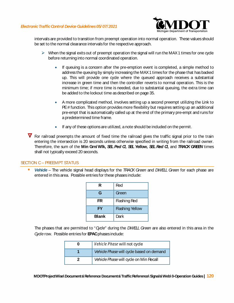
Electronic Traffic Control Device Guidelines 05/07/2021
MDOTProjectWise\Documents\Reference Documents\Traffic Reference\Signals\Web\0-Operation Guides | 120
intervals are provided to transition from preempt operation into normal operation. These values shouldbe set to the normal clearance intervals for the respective approach.
Ø When the signal exits out of preempt operation the signal will run the MAX 1 times for one cyclebefore returning into normal coordinated operation.
· If queuing is a concern after the pre-emption event is completed, a simple method toaddress the queuing by simply increasing the MAX 1 times for the phase that has backedup. This will provide one cycle where the queued approach receives a substantialincrease in green time and then the controller reverts to normal operation. This is theminimum time; if more time is needed, due to substantial queuing, the extra time canbe added to the lockout time as described on page 35.
· A more complicated method, involves setting up a second preempt utilizing the Link toPE # function. This option provides more flexibility but requires setting up an additionalpre-empt that is automatically called up at the end of the primary pre-empt and runs fora predetermined time frame.
· If any of these options are utilized, a note should be included on the permit.
For railroad preempts the amount of fixed time the railroad gives the traffic signal prior to the trainentering the intersection is 20 seconds unless otherwise specified in writing from the railroad owner.Therefore, the sum of the Min Grn/Wlk, SEL Ped Cl, SEL Yellow, SEL Red Cl, and TRACK GREEN timesshall not typically exceed 20 seconds.
SECTION C – PREEMPT STATUS
§ Vehicle – The vehicle signal head displays for the TRACK Green and DWELL Green for each phase areentered in this area. Possible entries for these phases include:
R Red
G Green
FR Flashing Red
FY Flashing Yellow
Blank Dark
The phases that are permitted to “Cycle” during the DWELL Green are also entered in this area in theCycle row. Possible entries for EPAC phases include:
0 Vehicle Phase will not cycle
1 Vehicle Phase will cycle based on demand
2 Vehicle Phase will cycle on Min Recall

Electronic Traffic Control Device Guidelines 05/07/2021
MDOTProjectWise\Documents\Reference Documents\Traffic Reference\Signals\Web\0-Operation Guides | 121
3 Vehicle Phase will cycle on Max Recall
§ Pedestrian – The pedestrian signal head displays for the TRACK Green and DWELL Green for eachphase/interval are entered in this area. Possible entries for these phases/intervals include:
DW Don’t Walk
W Walk
Blank Dark
The pedestrian phases that are permitted to “Cycle” during the DWELL Green are also entered in thisarea in the Cycle row. Possible entries for EPAC phases include:
0 Pedestrian Phase will not cycle
1 Pedestrian Phase will cycle based on demand
2 Pedestrian Phase will cycle on Recall
§ Overlap Vehicle - The vehicle signal head displays for the TRACK Green and DWELL Green for eachphase/interval are entered in this area for overlap vehicles. Possible entries for these phases/intervalsinclude:
R Red
G Green
FR Flash Red
FY Flash Yellow
The overlaps that are permitted to “Cycle” during the DWELL Green are also entered in this area in theCycle row. Possible entries for EPAC phases include:
0 Overlap Vehicle will not cycle
1 Overlap Vehicle will cycle based on service toincluded phases
SECTION D – MISCELLANEOUS PREEMPT PARAMETERS
§ Locking / Non-Locking
Electronic Traffic Control Device Guidelines 05/07/2021
MDOTProjectWise\Documents\Reference Documents\Traffic Reference\Signals\Web\0-Operation Guides | 122
Ø Non-Locking preempt memory: there is no memory storage of a preempt call. The preemptdetector must have a continuous call in order to maintain a call for service of the preemptroutine.
Ø Locking preempt memory: once a preempt detector gets a call, this call is “locked” in andremains a constant call until the preempt routine is serviced.
§ Delay – This denotes the number of seconds (0-999) that the Preempt actuation must be active beforenormal controller operations are interrupted for the Preempt routine.
§ Extend – This denotes the number of seconds (0-999) that each Preempt actuation shall be extendedfrom the point the actuation terminates.
§ Duration – This denotes the number of seconds (0-999) which a Preempt requires prior to a transitionback to normal traffic operations can occur.
§ Max Call – This establishes the number of seconds (0-999) which a Preempt call may remain active andbe considered valid.
§ Lockout – This establishes the number of seconds (0-999) following the exit from the Preempt Routinethat will occur prior to entering a Low Priority Routine.
Ø When this value is “0”, Lockout will be in effect until:
· No serviceable Conflicting Call Exists or
· Any phase is re-serviced following the exit.
§ Link PE # - This establishes the higher priority Preempt routine which is to be linked to this Preemptroutine.
SECTION E – REMARKS
Section E is the REMARKS section. Any information that is necessary for the proper installation of the signaltiming permit that was not captured by the fields of the signal timing permit should be entered in this section. Ifall of the remarks do not fit into the space provided, do not change the font size as MDOT will lose all of thisinformation in their database when the font is changed.
If a timing permit is prepared by a consultant, the consultant name should be included in the remarkssection. For example:
“OPTIMIZED BY (Insert Organization Name)”
SECTION F – LOCATION
Section F provides general information about the signalized location including:
Electronic Traffic Control Device Guidelines 05/07/2021
MDOTProjectWise\Documents\Reference Documents\Traffic Reference\Signals\Web\0-Operation Guides | 123
§ Who prepared the timing permit and the date
§ The location and control section-spot number
This data automatically transfers from the first page.
7.3 EPIC/EF-140 CONTROLLER UNITS
7.3.1 BASIC TIMING PARAMETERS FORM – EPIC/EF-140 CONTROLLER UNITS
The EPIC and EF-140 controller units are interval–based pre-timed traffic controller units. Limited vehicle andpedestrian actuation can be accommodated through the use of detectors and alternate pre-timed paths enteredinto the interval sequences. The procedures for completing timing permits for pre-timed and actuated(alternate path) formats are detailed below, respectively.
PRE-TIMED EPIC/EF-140 CONTROLLER TIMING PERMIT
Figure 7-12 represents a sample signal timing permit sheet for an EPIC or EF-140 controller operating in pre-timed mode. The sample illustrates a signal with lagging permitted-protected left-turns on Main Street, andpedestrian crosswalks provided on both Main Street and Lansing Street. A description of each section (A – E) ofthe signal timing permit, and how to properly fill in these sections, is provided in the text that follows. All of thegeneral information (Sections 1-5) is presented under Section 7.4 Standard Information: Page 1. The ranges andincrements for the timed values entered into the timing permit are provided in Table 7-1212.
Figure 7-12: EPIC/EF-140 Pre-Timed Permit Example
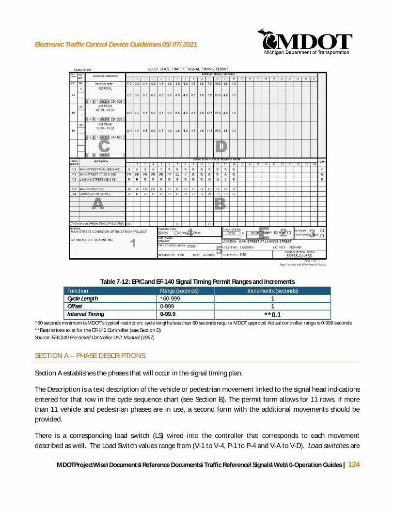
Electronic Traffic Control Device Guidelines 05/07/2021
MDOTProjectWise\Documents\Reference Documents\Traffic Reference\Signals\Web\0-Operation Guides | 124
Table 7-12: EPIC and EF-140 Signal Timing Permit Ranges and IncrementsFunction Range (seconds) Increments (seconds)Cycle Length *60-999 1Offset 0-999 1Interval Timing 0-99.9 **0.1
*60 seconds minimum is MDOT’s typical restriction; cycle lengths less than 60 seconds require MDOT approval Actual controller range is 0-999 seconds**Restrictions exist for the EF-140 Controller (see Section D)Source: EPIC140 Pre-timed Controller Unit Manual (1997)
SECTION A – PHASE DESCRIPTIONS
Section A establishes the phases that will occur in the signal timing plan.
The Description is a text description of the vehicle or pedestrian movement linked to the signal head indicationsentered for that row in the cycle sequence chart (see Section B). The permit form allows for 11 rows. If morethan 11 vehicle and pedestrian phases are in use, a second form with the additional movements should beprovided.
There is a corresponding load switch (LS) wired into the controller that corresponds to each movementdescribed as well. The Load Switch values range from (V-1 to V-4, P-1 to P-4 and V-A to V-D). Load switches are

Electronic Traffic Control Device Guidelines 05/07/2021
MDOTProjectWise\Documents\Reference Documents\Traffic Reference\Signals\Web\0-Operation Guides | 125
devices that switch the load current to the appropriate indication (phase red, green or yellow). Each load switchconsists of three outputs into the field load bay which connect to a field terminal. These load switches allow alow voltage signal from the Controller Unit to control the delivery of high current and voltage to the traffic signalload.
Standard load switch assignments for a cabinet with 8 load switches are as follows:
LS1(V-1) and LS2(V-2) are typically used for vehicle movements and LS3(V-3) and LS4(V-4) are used for thepedestrian signals associated with LS1 and LS2, respectively. LS5(P-1) and LS6(P-2) are typically used for vehiclemovements and LS7(P-3) and LS8(P-4) are used for the pedestrian signals associated with LS6 and LS5,respectively.
Standard load switch assignments for a cabinet with 12 load switches are as follows:
LS1(V-1) through LS4(V-4) and LS5(P-1) through LS8(P-4) are used for vehicle movements. LS9(V-A), LS10(V-B),LS11(V-C), and LS12(V-D) are used for pedestrian signals associated with vehicle movements LS2, LS4, LS6, andLS8 respectively.
While these are the typical convention, individual intersections may utilize them differently. The value for theload switch will typically need to be obtained from the existing timing permit or from the controller cabinet.
SECTION B – CYCLE SEQUENCE CHART
The cycle sequence chart in Section B is where the signal indication is entered for each interval. Each rowcorresponds to the phase defined in Section A. Possible entries for these intervals include:
G Green
GL Green Left Arrow
GR Green Right Arrow
R Red (used for ball or arrow)
FR Flashing Red
Y Yellow (used for ball or arrow)
FY Flashing Yellow
W Walk
D Don’t Walk
FD Flash Don’t Walk
Some indications for turning movement simply go dark during parts of the cycle. When the indication is dark,simply leave those intervals blank.

Electronic Traffic Control Device Guidelines 05/07/2021
MDOTProjectWise\Documents\Reference Documents\Traffic Reference\Signals\Web\0-Operation Guides | 126
Twenty-four (24) intervals are provided on the signal timing permit to enter the signal indication for each phasedescription. The EPIC and EF-140 controllers allow for up to 32 intervals of data entry. Should more than the 24intervals be needed, a second sheet may be attached. The second sheet should note in the Remarks Section(Section G1) that interval one of that sheet is actually interval 25. Interval eight (8) on the second sheet will bethe last interval possible for data entry, as it represents interval 32 in the controller unit.
At signalized locations with no pedestrian signals, it was common for the green-time of individual splits to bedivided into more than one interval to accommodate for potential future pedestrian signal intervals. This is aremnant of the EF-140 controllers that required a permanently burnt in PROM chip, which limited the ability toadd intervals at a later date without burning a new PROM chip. With the advent of EPIC controllers the duplicateintervals were often still utilized even though they were not necessary. The duplicate intervals should not beremoved when updating the permit. This is intended to minimize the potential for errors during theprogramming of the controllers. If the controller is being modernized, all interval information will need to beentered regardless and the unnecessary intervals should be eliminated. Duplicate intervals can be eliminatedonly if the intervals are forced to be redone, such as adding an all red or trail green to the signal.
Where duplicate intervals do exist, the minimum green time should be split roughly equally between themand the interval time for the second interval should be set equal to the minimum time for all dial/splitcombinations. This will cause all changes in splits along with correction to occur in the first of the duplicateintervals. In addition, if a pedestrian crossing is present at the intersection duplicate intervals for the vehiclephase are needed to accommodate the walk time and all or a portion of the pedestrian clearance interval. Itis typical to have the minimum time for the second interval of a phased be governed by all or a portion ofthe pedestrian clearance time.
The last column in Section B denotes the state of the signal indication for each respective vehicle phase whenthe controller is in Flash Mode. Entries here should be Y (yellow), R (red) or Blank (dark). In the event conflictflash and scheduled flash operations are different, the remarks section should be updated to clarify.
Into and Out of Flash
The last row in Section B denotes the entry/exit interval for the flash mode and the intervals that can be used foroffset correction operation. The entry interval should be designated with an “I” for Into Flash, and the exitinterval should be designated with an “O” for Out of Flash. The Into Flash transition will occur at the end of thespecified interval. The Out of Flash transition will occur at the beginning of the specified interval. The signal willtypically enter Into Flash at the end of the side road’s All Red interval. The signal will typically come Out of Flashat the beginning of interval 1, or the main street’s green. If pedestrian push buttons are present and the lastinterval is a main street green, do not exit Out of Flash in this interval. If there is no flash schedule the Into andOut of Flash intervals should still be entered to account for power outages.
Correction Intervals

Electronic Traffic Control Device Guidelines 05/07/2021
MDOTProjectWise\Documents\Reference Documents\Traffic Reference\Signals\Web\0-Operation Guides | 127
The intervals used for offset correction operation should be designated with a “C”. Correction is allowed inintervals that are not timing a clearance interval (Yellow, All Red or Flashing Don’t Walk). Typically these will begreen/walk intervals. Multiple intervals can and should be coded for correction if the minimum times allow forit. With multiple correction intervals the coordinator will split the correction time for each cycle proportionallyamong the correction intervals based on the difference in the correction intervals between the Min time andinterval time provided in the Dial/Split data. This is true for all correction modes including Dwell, Dwell withInterrupt, Short Way, and Short Way +. If there are multiple green/walk intervals for a phase, set one interval tobe the same for all dial/split combinations and make changes to the other interval. For the interval that doesnot change, try to set the minimum time equal to the interval time. This will ensure that the correction does notoccur during this interval.
Before allowing correction in an interval, it should be verified that the interval times EXCEED the minimumtime for the interval or Short Way correction should not be used (see Section D for more details onminimum times and Section 7.3.2 for details on Correction Mode).
For an interval in which correction is being considered, if some Dials allow for correction but others don’t,code it to provide correction. For the dials in which there is no additional time beyond the minimum time,the controller will correct in other intervals.
If the signal is an EF-140, leave the Correction and Into/Out of Flash off of the permit because what iscurrently in operation is unknown and is permanently burned into the PROM.
SECTION C – DIAL SET-UP
Section C is the dial data section. It establishes the pre-timed cycle lengths, offsets, and hours of operation forup to four timing plans. A controller can accommodate up to four dials, and each dial can accommodate up tofour different splits, allowing a controller to accommodate up to 16 different timing plans total. Each dial/splitcombination can accommodate up to 3 offsets. Under typical conditions, MDOT’s standard convention is to useDial 1, Split 1, Offset 1 for normal “off-peak” operation, Dial 2, Split 1, Offset 1 for the AM peak period, and Dial3, Split 1, Offset 1 for the PM peak period. Construction and special event timing plans should be placed in Dial4. However, assignment of dials may vary depending on maintaining agency and should therefore bedetermined in advance of preparing a timing permit. If more than the four timing plans provided on the firstpage of the permit are needed, there are spots for up to four additional timing plans available on the secondpage (see Section 7.3.2).
§ CYCLE LENGTH – The first column is where the cycle length is entered, in seconds, for each dial inoperation.
§ OFFSET – The second column is where the offset is entered, in seconds, from the system zero time foreach dial in operation. Up to three offsets can be entered for each split. For uncoordinated locations,enter zero.

Electronic Traffic Control Device Guidelines 05/07/2021
MDOTProjectWise\Documents\Reference Documents\Traffic Reference\Signals\Web\0-Operation Guides | 128
§ HOURS OF OPERATION – The hours and days of the week of operation for each dial in operation areentered here. A timing plan must be designated for all time periods 24-hours a day, seven days a week,except for the hours where the signal is designated to operate in flash mode (see Section F). Dial 1, Split1, Offset 1 is often simply designated as “Normal.” This implies that for any time period in whichanother dial-split combination is not called out and the signal is not in nighttime flash mode, the signalwill run this plan.
§ Dial Split Designation – The dial and split number are entered below the Hours of Operation. Both thedial and split can range from (1-4). Default values of (D1/S1, D2/S1, and D3/S1) have been entered inthe first three timing plans. If necessary, these values may be overridden.
§ Phase Split Times – The split times, in seconds, for each phase can be entered in the box provided forsplits. For example, the splits in the example for D1/S1 are 28/14/28. If the splits are variable due tovehicle detection or pedestrian push buttons, this entry may be left blank.
Valid offset entries for EF-140 controllers range from zero to the cycle length minus one second. An offsetequal to the cycle length will make the controller run free on that particular dial. An offset greater than thecycle length is invalid and the dial will not run.
Valid offset entries for EPIC controllers range from zero to the cycle length minus one second. An offsetgreater than or equal to the cycle length will make the controller run free on that particular dial.
For an EF-140 controller, the OFFSET time, when subtracted from the end of the cycle, should not occurduring a yellow or all-red interval when used in a coordinated system. During dial changes or othersynchronization periods, the controller will dwell at the offset point until the clock reaches synchronizationwith the system time. If the offset point occurs within a yellow or all-red interval, the signal will dwell inthat interval, leading to lengthened clearance interval that may confuse drivers. Offsets should thereforealways be designated to fall within a green interval.
SECTION D – INTERVAL TIMING
The interval timing section is where the length of the intervals is entered for each dial in operation as well as theminimum times for each interval (Minimum Time row is above the first Dial-Split row). The interval lengthsentered in Section D correspond to the length of the signal indications entered in Section B.
Minimum times should reflect the minimum Yellow, All-Red, or Flash Don’t Walk intervals, as calculated perMDOT’s clearance interval methodology (See chapter 4.0 for details). In addition, minimum Walk and InitialGreen intervals should be entered based on MDOT standards wherever possible. The minimum standards are asfollows:
§ Minimum Green for major roadway – 10.0 seconds
§ Minimum Green for minor roadway/cross-street – 7.0 seconds

Electronic Traffic Control Device Guidelines 05/07/2021
MDOTProjectWise\Documents\Reference Documents\Traffic Reference\Signals\Web\0-Operation Guides | 129
§ Minimum Green for all left-turn phasing with the exception of actuated permitted-protected left-turnphasing – 7.0 seconds
§ Minimum Green for actuated permitted-protected left-turn phasing – 5.0 seconds
§ Minimum WALK time – 7.0 seconds
A Minimum Green of 5.0 seconds may be used for a protected left-turn phase with MDOT approval. This wouldbe considered when the left-turn volume is extremely low and the additional 2.0 seconds taken from the left-turn would provide a significant benefit to the other phases of the signal. A minimum WALK time of 4.0 secondsmay be used, where deemed appropriate based on pedestrian volumes and timing requirements, with approvalof MDOT.
If there are duplicate green/walk intervals, the minimum times should be set such that the total of the twointervals is equal to the minimum times above.
For an EF-140 controller, the interval time may only be entered with a decimal place up to 12.7 seconds.Any interval time above 12.7 seconds must be entered as a whole number.
For an EF-140 controller, the minimum times are fixed (burned) into the controller and are not easilyadjustable. Typically, these minimum times will be left alone and not adjusted. If there is a need to adjustthe minimum times, the MDOT project manager will need to approve.
Interval times should always equal or exceed the minimum times. If the minimum time for an intervalexceeds the interval time for a Dial-Split, the minimum time will be run and the signal will not stay incoordination.
SECTION E – FLASH SCHEDULE
Information for determining an appropriate flash schedule can be found in Section 5.2.7.
ACTUATED EPIC/EF-140 CONTROLLER TIMING PERMIT
The EPIC and EF-140 controller units do have limited actuation capabilities through the use of multiple pre-timedpaths. The pre-timed path to be followed is determined by calls (or the absence of calls) placed by vehicle andpedestrian detectors. For the EPIC controller unit, there are two detector groups; Detector A and Detector B.Each detector group allows for a pedestrian and vehicle call.
The majority of the timing permit for operation in actuated mode is completed similarly to that of pre-timedcontrol (see Section 0) However, multiple paths must be established in the Cycle Sequence Chart and IntervalTiming Chart, corresponding to the various timing sequences, should detector calls occur. Figure 7-13 illustratesa sample signal timing permit for an EPIC or EF-140 controller operating in actuated mode, with multiple pre-timed paths. A description of how to complete each affected section of the signal timing permit to reflectoperation in actuated mode follows.

Electronic Traffic Control Device Guidelines 05/07/2021
MDOTProjectWise\Documents\Reference Documents\Traffic Reference\Signals\Web\0-Operation Guides | 130
Figure 7-13: EPIC/EF-140 Actuated Timing Permit Example
SECTION A – CYCLE SEQUENCE CHART
The cycle sequence chart is used to define the signal indications throughout a series of actuated “paths”. Thevarious signal paths are denoted with actuation codes. The actuation codes and their descriptions are shown inTable 7-1313. Typical multi-path sequences are illustrated in Figure 7-14.
Table 7-13: Actuation Codes and DescriptionsCode Description Sequence Restrictions
0(Non-Actuated)
Interval is not actuated and will always run. An interval with code “0”also serves as a choice interval during which the controller unitdetermines which interval to run next, given two or more branches inthe interval path. This is the only interval during which the controlleraccepts detector calls.
Must be included in all actuatedtiming plans and will precede allother codes used.
1 (Either) Indicates that a call on either one of the two detector groups willprovide the same signal displays in response to detector actuationsregardless of which detector calls are received on.
Code “1” (if used) must follow Code“0”. Must precede Codes “2”, “3” or“4” (if used), or Codes “6” and “7” (ifused).
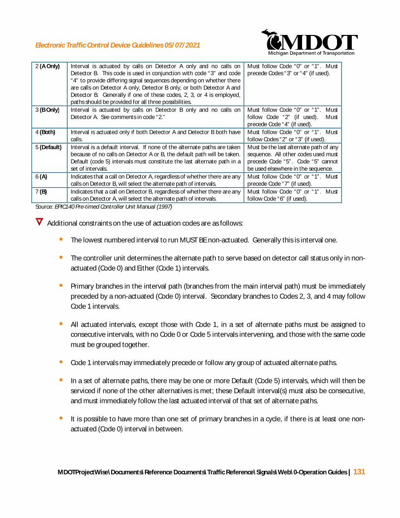
Electronic Traffic Control Device Guidelines 05/07/2021
MDOTProjectWise\Documents\Reference Documents\Traffic Reference\Signals\Web\0-Operation Guides | 131
2 (A Only) Interval is actuated by calls on Detector A only and no calls onDetector B. This code is used in conjunction with code “3” and code“4” to provide differing signal sequences depending on whether thereare calls on Detector A only, Detector B only, or both Detector A andDetector B. Generally if one of these codes, 2, 3, or 4 is employed,paths should be provided for all three possibilities.
Must follow Code “0” or “1”. Mustprecede Codes “3” or “4” (if used).
3 (B Only) Interval is actuated by calls on Detector B only and no calls onDetector A. See comments in code “2.”
Must follow Code “0” or “1”. Mustfollow Code “2” (if used). Mustprecede Code “4” (if used).
4 (Both) Interval is actuated only if both Detector A and Detector B both havecalls.
Must follow Code “0” or “1”. Mustfollow Codes “2” or “3” (if used).
5 (Default) Interval is a default interval. If none of the alternate paths are takenbecause of no calls on Detector A or B, the default path will be taken.Default (code 5) intervals must constitute the last alternate path in aset of intervals.
Must be the last alternate path of anysequence. All other codes used mustprecede Code “5”. Code “5” cannotbe used elsewhere in the sequence.
6 (A) Indicates that a call on Detector A, regardless of whether there are anycalls on Detector B, will select the alternate path of intervals.
Must follow Code “0” or “1”. Mustprecede Code “7” (if used).
7 (B) Indicates that a call on Detector B, regardless of whether there are anycalls on Detector A, will select the alternate path of intervals.
Must follow Code “0” or “1”. Mustfollow Code “6” (if used).
Source: EPIC140 Pre-timed Controller Unit Manual (1997)
Additional constraints on the use of actuation codes are as follows:
§ The lowest numbered interval to run MUST BE non-actuated. Generally this is interval one.
§ The controller unit determines the alternate path to serve based on detector call status only in non-actuated (Code 0) and Either (Code 1) intervals.
§ Primary branches in the interval path (branches from the main interval path) must be immediatelypreceded by a non-actuated (Code 0) interval. Secondary branches to Codes 2, 3, and 4 may followCode 1 intervals.
§ All actuated intervals, except those with Code 1, in a set of alternate paths must be assigned toconsecutive intervals, with no Code 0 or Code 5 intervals intervening, and those with the same codemust be grouped together.
§ Code 1 intervals may immediately precede or follow any group of actuated alternate paths.
§ In a set of alternate paths, there may be one or more Default (Code 5) intervals, which will then beserviced if none of the other alternatives is met; these Default interval(s) must also be consecutive,and must immediately follow the last actuated interval of that set of alternate paths.
§ It is possible to have more than one set of primary branches in a cycle, if there is at least one non-actuated (Code 0) interval in between.

Electronic Traffic Control Device Guidelines 05/07/2021
MDOTProjectWise\Documents\Reference Documents\Traffic Reference\Signals\Web\0-Operation Guides | 132
§ In branches with alternate paths Codes 6 and 7, if there are calls on both detectors, the path withthe LOWER-numbered intervals will be serviced.
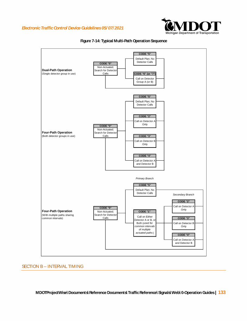
Electronic Traffic Control Device Guidelines 05/07/2021
MDOTProjectWise\Documents\Reference Documents\Traffic Reference\Signals\Web\0-Operation Guides | 133
Figure 7-14: Typical Multi-Path Operation Sequence
SECTION B – INTERVAL TIMING
CODE "5"
(Single detector group in use) CODE "6" (or "7")
CODE "5"
CODE "2"
(Both detector groups in use) CODE "3"
CODE "4"
Primary Branch
CODE "5"
Secondary Branch
CODE "2"
CODE "1"
CODE "3"
CODE "4"
Dual-Path Operation
(With multiple paths sharingcommon intervals)
Call on Detector BOnly
Call on Detector AOnly
Default Plan; NoDetector Calls
Call on Detector AOnlyCODE "0"
Call on Detector Aand Detector B
Call on EitherDetector A or B, or
Both (used forcommon intervals
of multipleactuated paths )
Non-Actuated;Search for Detector
Calls
Four-Path Operation
Four-Path Operation
Call on Detector Aand Detector B
Default Plan; NoDetector Calls
CODE "0"
Non-Actuated;Search for Detector
Calls
Call on Detector BOnly
Default Plan; NoDetector Calls
Call on DetectorGroup A (or B)
CODE "0"Non-Actuated;
Search for DetectorCalls

Electronic Traffic Control Device Guidelines 05/07/2021
MDOTProjectWise\Documents\Reference Documents\Traffic Reference\Signals\Web\0-Operation Guides | 134
Timings for each interval in actuated mode are governed by the same restrictions as those of pre-timedlocations as discussed in Section 7.1. However, care must be taken to assure that timings for each path equalthe defined cycle length for each dial. The following is an example taken from the sample permit illustrated inFigure 7-13:
Example: The intersection of Main Street and Lansing Road operates with two paths: the default path (if nodetector calls are received), and the actuated path (if a call is received on Detector A).
§ Default Path (0→5): The default path is comprised of intervals with actuation codes “0” and “5”. In thiscase, this includes Interval 1-8, and Intervals 9-11. Therefore, the sum of timings for Dial 1, intervals 1-8and 9-11must equal the cycle length of 70 seconds.
§ Actuated Path (0→6): The actuated path is comprised of intervals with actuation codes “0” and “6”. Inthis case, this includes Intervals 1-8, and Interval 12. Therefore, the sum of timings for Dial 1, intervals1-8 and 12 must equal the cycle length of 70 seconds.
EPIC/EF-140 controllers are not capable of extending a cycle length based on detector calls received. Allalternative path intervals must independently sum to the assigned cycle length for that dial.
MISCELLANEOUS ACTUATED OPTIONS
EXTEND and DELAY times can also be used in association with actuated intervals.
§ EXTEND – When in the actuated intervals associated with the detector, an actuation (input duration)shall be extended from the point of termination by the EXTEND time entered (0-99.9 seconds). EXTENDtimes and the intervals they pertain to should be described in the REMARKS section (Section G1).
§ DELAY – When not in the actuated intervals associated with the detector, a detector actuation shall bedelayed by the DELAY time. Once the actuation has been present for the DELAY time, it shall becontinued for as long as it is present (0-99.9 seconds). DELAY times and the intervals they pertain toshould be described in the REMARKS section (Section G1).
EXTEND timings do not apply to “Either” or “Default” path intervals in regard to FORCE INTERVALS andextend/gap operation. DELAY is operational in “Either” or “Default” path intervals and disabled in otherpath intervals.
FORCE INTERVALS
Though not commonly used, the EPIC/EF-140 controllers have the capability of variable time intervals calledFORCE INTERVALS. A FORCE INTERVAL is an actuated interval with the capability to terminate early if there areno detector calls. The remaining time from the actuated interval is then distributed to a non-actuated intervalso that the cycle length remains unchanged.
Electronic Traffic Control Device Guidelines 05/07/2021
MDOTProjectWise\Documents\Reference Documents\Traffic Reference\Signals\Web\0-Operation Guides | 135
Any actuated green interval can be specified as a FORCE INTERVAL. If there are no calls currently present on adetector when an actuated path is used, a FORCE INTERVAL will terminate early with at least the MINIMUMTIME for the actuated interval in use. The remaining time from the FORCE INTERVAL that was unused isdistributed to the next non-actuated interval in the controller path (this is typically a main street green interval).If there are constant calls on the detector, the FORCE INTERVAL will run the full interval time listed for the timingplan.
Because it is not common for EPIC/EF-140 controllers to use FORCE INTERVALS, the current timing permit doesnot provide areas for the specification of FORCE INTERVALS or the EXTEND/DELAY times. If FORCE INTERVALS orEXTEND/DELAY times are used, this information should be described in the REMARKS section (Section G1) afterconsulting the EPIC controller manual for more detail.
7.3.2 ADVANCED TIMING PARAMETERS FORM – EPIC/EF-140 CONTROLLER
The Advanced Timing Parameters form (page 2) provides the system data, signal operation parameters, andspace to provide additional dial and split information. This form is meant to be used for EPIC/EF-140 signalcontrollers and should always be included as part of the signal timing permit.
Figure 7-15 illustrates a sample Advanced Timing Parameters form filled out. A description of each section (A –C) of the signal timing permit and how to properly fill in these sections is provided in the text that follows. All ofthe general information (sections 1 - 5) is presented under the General Permit Guidelines in Section 7.5. Table7-1414 provides the ranges and increments for the numerical values included on this form.
Figure 7-15: Advanced Timing Parameters Form (EPIC) Example
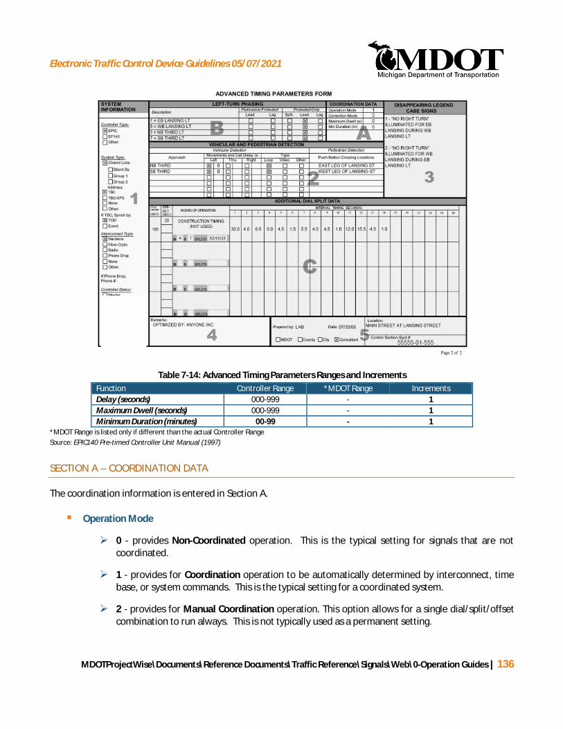
Electronic Traffic Control Device Guidelines 05/07/2021
MDOTProjectWise\Documents\Reference Documents\Traffic Reference\Signals\Web\0-Operation Guides | 136
Table 7-14: Advanced Timing Parameters Ranges and IncrementsFunction Controller Range *MDOT Range IncrementsDelay (seconds) 000-999 - 1Maximum Dwell (seconds) 000-999 - 1Minimum Duration (minutes) 00-99 - 1
*MDOT Range is listed only if different than the actual Controller RangeSource: EPIC140 Pre-timed Controller Unit Manual (1997)
SECTION A – COORDINATION DATA
The coordination information is entered in Section A.
§ Operation Mode
Ø 0 - provides Non-Coordinated operation. This is the typical setting for signals that are notcoordinated.
Ø 1 - provides for Coordination operation to be automatically determined by interconnect, timebase, or system commands. This is the typical setting for a coordinated system.
Ø 2 - provides for Manual Coordination operation. This option allows for a single dial/split/offsetcombination to run always. This is not typically used as a permanent setting.
Electronic Traffic Control Device Guidelines 05/07/2021
MDOTProjectWise\Documents\Reference Documents\Traffic Reference\Signals\Web\0-Operation Guides | 137
§ Correction Mode – The correction mode determines how the signal will adjust the timing in order tomove the offset to the correct value. It will typically not violate the minimum interval times. The offsetmay be off for a variety of common reasons (when the signal changes timing plans throughout the day,when it comes out of night time flash mode, after a power outage, etc.). The correction mode willtypically be found in the controller.
Ø 0 – Dwell: causes the signal to dwell in a compatible interval beyond the time defined for theinterval until the correction has been accomplished. This correction mode is not typically used.Especially at locations with high cycle lengths, it can cause the signal to dwell in one phase for anexcessive length of time.
Ø 1 – Max Dwell: causes the signal to dwell in the same manner, but limits the maximum amountof time the signal can dwell per cycle. If the correction cannot be completed in one cycle, thesignal will continue to correct in future cycles until the offset is correct.
Ø 2 – Short Way: allows the signal to dwell or if it can correct the offset faster by reducing thetime provided for intervals it will do that. Correction will not exceed 20% in a cycle and willautomatically take into consideration minimum times.
· Short Way correction is the preferred correction, but it requires the sum of thedifference between the interval times (that the correction is applied to) and therespective interval minimum times to exceed at least 19% of the cycle length.
Ø 3 – Short Way+: this correction mode is identical to Max Dwell except the Maximum Correctionwill not exceed 20% in a cycle. This mode does not reduce interval times to adjust the offset.
§ Maximum Dwell – This value establishes the maximum time the unit may dwell for offset correction in asingle cycle when the correction mode is set to Max Dwell. This value may range from (0-999 seconds).
§ Minimum Duration – This value establishes the minimum time a dial/spit/offset pattern will run. Thisvalue may range from (0-99 minutes). This is typically only a concern for closed loops running TrafficResponsive. Depending on the timing, it can take upwards of 10 minutes for a system to get in stepafter a dial/split/offset change. If the system changes dial-splits too often, it will spend a largepercentage of time correcting rather than running the plan. While correcting, progression is typicallydisrupted.
If the controller is an EF-140 controller, leave the coordination data blank as what is currently running isunknown and the data may be burnt into the PROM.
With Short Way correction, it is important that the correction intervals have interval times that EXCEED theminimum time. If this is not accounted for, it is possible for the signal to get caught in an endless loop as ittries to subtract time from an interval and the minimum times do not allow for it. If this happens, the signalwill never be able to correct the offset.
SECTION B – LEFT-TURN PHASING
Electronic Traffic Control Device Guidelines 05/07/2021
MDOTProjectWise\Documents\Reference Documents\Traffic Reference\Signals\Web\0-Operation Guides | 138
The LEFT-TURN PHASING information is entered in Section B. The left-turn Phase # / Phase Descriptioninformation as well as Permissive-Protected and Protected Only information are entered in this section.
§ Load Switch # / Phase Description – The load switch number, followed by a description of the phase areentered in this area.
§ Permissive-Protected and Protected-Only Phasing – In this section, the left-turn operation should bedefined as either a “leading,” “lagging,” or “split” phase (relative to the parallel through movement), andwhether permissive movement of that phase is allowed during the companion through phase. Only onebox should be checked for each phase.
SECTION C – ADDITIONAL DIAL AND SPLIT DATA
There are four additional timing plans that may be entered in this section. See section D of the Basic TimingParameters Form (Section 7.3.1) for more information.
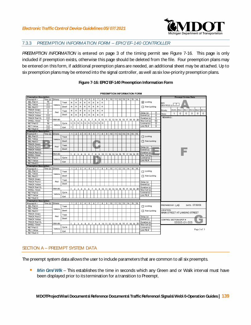
Electronic Traffic Control Device Guidelines 05/07/2021
MDOTProjectWise\Documents\Reference Documents\Traffic Reference\Signals\Web\0-Operation Guides | 139
7.3.3 PREEMPTION INFORMATION FORM – EPIC/EF-140 CONTROLLER
PREEMPTION INFORMATION is entered on page 3 of the timing permit see Figure 7-16. This page is onlyincluded if preemption exists, otherwise this page should be deleted from the file. Four preemption plans maybe entered on this form, if additional preemption plans are needed, an additional sheet may be attached. Up tosix preemption plans may be entered into the signal controller, as well as six low-priority preemption plans.
Figure 7-16: EPIC/EF-140 Preemption Information Form
SECTION A – PREEMPT SYSTEM DATA
The preempt system data allows the user to include parameters that are common to all six preempts.
§ Min Grn/Wlk – This establishes the time in seconds which any Green and or Walk interval must havebeen displayed prior to its termination for a transition to Preempt.

Electronic Traffic Control Device Guidelines 05/07/2021
MDOTProjectWise\Documents\Reference Documents\Traffic Reference\Signals\Web\0-Operation Guides | 140
§ Priority and Status – The entry (Code “0” = NO and Code “1” = YES) establishes whether the firstfunction has priority over the second. An entry of “0” indicates no priority between the two. When afunction has priority over another, the function of lower priority will terminate and the higher prioritywill assume control.
PE/FL – Preemption over Remote Flash
PE1/2 – Preempt 1 over Preempt 2
PE2/3 – Preempt 2 over Preempt 3
PE3/4 – Preempt 3 over Preempt 4
PE4/5 – Preempt 4 over Preempt 5
PE5/6 – Preempt 5 over Preempt 6
SECTION B – PREEMPT INTERVAL TIMES
§ Preemption Description – Enter a description of the preemption here.
§ Preempt Number – Indicate which of the 6 available preempts is being defined. If more than fourpreempt plans exist, then an additional form should be attached for the additional preempts.
§ SEL Ped Cl, SEL Yellow, SEL Red Cl – The “Selective” clearance intervals are provided to transition fromnormal operation into a preempt. These values should typically be set to the highest value from thevarious phases in operation. For example, at a two-phase signal where the normal pedestrian clearanceis 12-seconds for one phase and 14-seconds for the second phase, 14-seconds would be entered for theSEL Ped CL as it is the larger of the two phases. The phase that it is transitioning to generally does notneed to be considered unless there is a track green being utilized.
Ø The exception to this is at some rail road crossings, the signal from the train does not trigger thepreempt soon enough to run all of the clearance intervals prior to the train arriving. Whensetting minimum times within preempts do not increase the SEL Ped Clearance without verifyingthat the increase can be accommodated. During preempts, the railroad will provide a fixedamount of time prior to the train entering the intersection. Often it is impractical to provideadditional advance notice. In the event this situation arises, the MDOT project manager shouldbe consulted prior to changing any of these values.
§ TRK Green, TRK Ped Cl, TRK Yellow, TRK Red Cl – The “Track” intervals are provided when a railroadtrack is located close to the intersection and they are intended to keep vehicles from queuing across thetrack. The intervals provide a short period of green as well as clearance intervals at the intersectionwhile the pre-signal at the tracks stays red. Doing this clears vehicles that were stopped on the trackswhile not allowing more vehicles on to the tracks. The “Track” intervals are typically used when thereare near and far signal heads at an intersection. The “Track” intervals clear vehicles between the nearand far signal head to avoid vehicle trapping.

Electronic Traffic Control Device Guidelines 05/07/2021
MDOTProjectWise\Documents\Reference Documents\Traffic Reference\Signals\Web\0-Operation Guides | 141
Ø TRACK GREEN interval provides the time for the TRACK Green. If no time is entered for theTRACK Green interval, the “Track” intervals will be skipped (Track Green, Track Ped Clear, TrackYellow, and Track Red Clear).
Ø The TRACK Ped Clear interval is the time provided to clear a terminating Walk during thetransition to DWELL Green.
Ø The TRACK Yellow interval is the time provided to clear a terminating Green during thetransition to DWELL Green.
Ø The TRACK Red Clear interval is the time provided to clear a terminating Yellow during thetransition to DWELL Green.
§ DWELL Green, RET Ped Cl, RET Yellow, RET Red Cl – The DWELL Green interval is the time that theintersection will dwell in green for the allowed phases during the preempt. The “Return” clearanceintervals are provided to transition from preempt operation into normal operation. These values shouldbe set to the normal clearance intervals for the respective approach.
For railroad preempts the amount of fixed time the railroad gives the traffic signal prior to the trainentering the intersection is 20 seconds unless otherwise specified in writing from the railroad owner.Therefore, the sum of the Min Grn/Wlk, SEL Ped Cl, SEL Yellow, SEL Red Cl, and TRACK GREEN timesshall not typically exceed 20 seconds.
SECTION C – PREEMPT SIGNAL DRIVERS
§ Vehicle – The vehicle signal head displays for the TRACK Green and DWELL Green for each driver areentered in this area. Possible entries for these drivers include:
R Red
G Green
Y Yellow
FR Flashing Red
FG Flashing Green
FY Flashing Yellow
RG Red and Green
Blank Dark
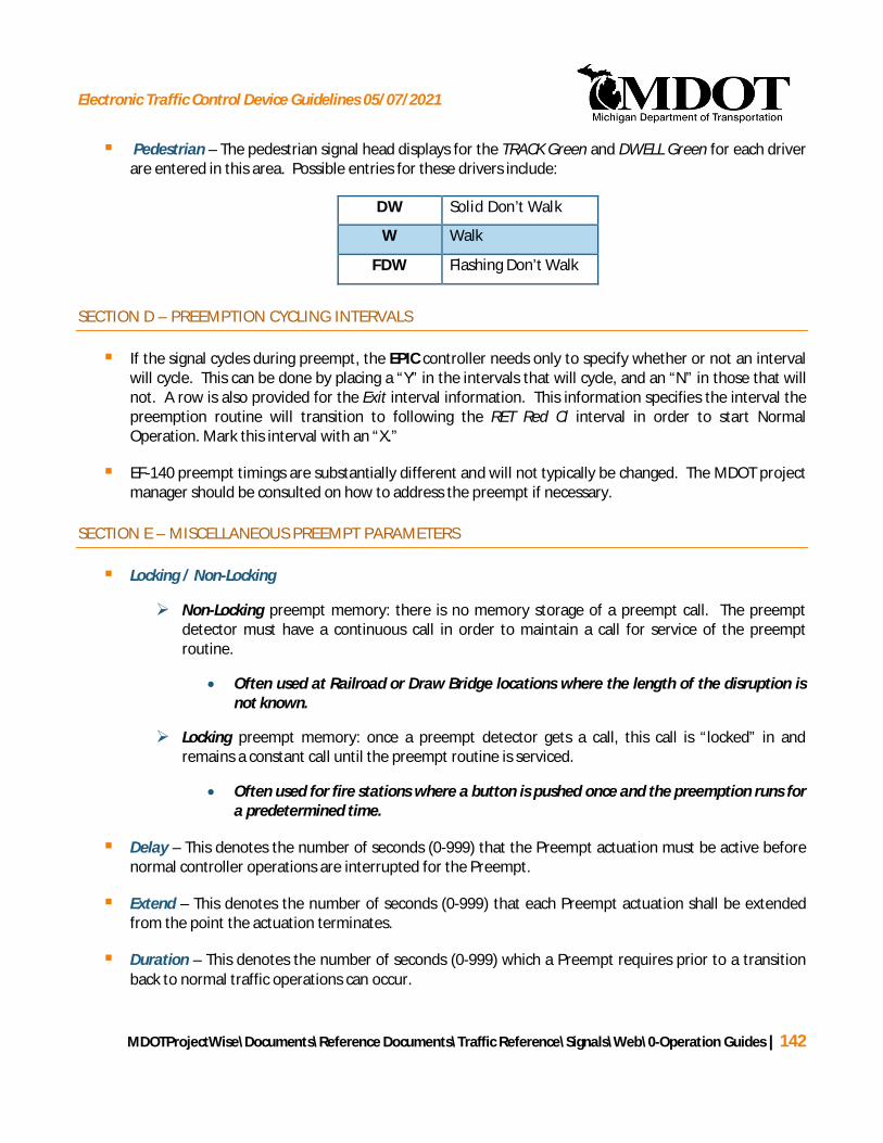
Electronic Traffic Control Device Guidelines 05/07/2021
MDOTProjectWise\Documents\Reference Documents\Traffic Reference\Signals\Web\0-Operation Guides | 142
§ Pedestrian – The pedestrian signal head displays for the TRACK Green and DWELL Green for each driverare entered in this area. Possible entries for these drivers include:
DW Solid Don’t Walk
W Walk
FDW Flashing Don’t Walk
SECTION D – PREEMPTION CYCLING INTERVALS
§ If the signal cycles during preempt, the EPIC controller needs only to specify whether or not an intervalwill cycle. This can be done by placing a “Y” in the intervals that will cycle, and an “N” in those that willnot. A row is also provided for the Exit interval information. This information specifies the interval thepreemption routine will transition to following the RET Red Cl interval in order to start NormalOperation. Mark this interval with an “X.”
§ EF-140 preempt timings are substantially different and will not typically be changed. The MDOT projectmanager should be consulted on how to address the preempt if necessary.
SECTION E – MISCELLANEOUS PREEMPT PARAMETERS
§ Locking / Non-Locking
Ø Non-Locking preempt memory: there is no memory storage of a preempt call. The preemptdetector must have a continuous call in order to maintain a call for service of the preemptroutine.
· Often used at Railroad or Draw Bridge locations where the length of the disruption isnot known.
Ø Locking preempt memory: once a preempt detector gets a call, this call is “locked” in andremains a constant call until the preempt routine is serviced.
· Often used for fire stations where a button is pushed once and the preemption runs fora predetermined time.
§ Delay – This denotes the number of seconds (0-999) that the Preempt actuation must be active beforenormal controller operations are interrupted for the Preempt.
§ Extend – This denotes the number of seconds (0-999) that each Preempt actuation shall be extendedfrom the point the actuation terminates.
§ Duration – This denotes the number of seconds (0-999) which a Preempt requires prior to a transitionback to normal traffic operations can occur.

Electronic Traffic Control Device Guidelines 05/07/2021
MDOTProjectWise\Documents\Reference Documents\Traffic Reference\Signals\Web\0-Operation Guides | 143
§ Max Call – This establishes the number of seconds (0-999) which a Preempt call may remain active.When the preempt call has been active for this time period, the controller shall return to normaloperation.
§ Lockout – This establishes the number of seconds (0-999) following the exit from the Preempt Routinethat will occur prior to entering a Low Priority Routine.
Ø When this value is “0”, Lockout will be in effect until:
· No serviceable Conflicting Call Exists or
· Any phase is re-serviced following the exit.
§ Link PE # - This establishes the higher priority Preempt routine which is to be linked to this Preemptroutine.
SECTION F – REMARKS
Section F is the REMARKS section. Any information that is necessary for the proper installation of the signaltiming permit that was not captured by the fields of the signal timing permit should be entered in this section. Ifall of the remarks do not fit into the space provided, do not change the font size as MDOT will lose all of thisinformation in their database when the font is changed.
SECTION G – LOCATION
Section G provides general information about the signalized location including:
§ Who prepared the timing permit and the date.
§ The location and control section-spot number.
This data automatically transfers from the first page.

Electronic Traffic Control Device Guidelines 05/07/2021
MDOTProjectWise\Documents\Reference Documents\Traffic Reference\Signals\Web\0-Operation Guides | 144
7.47.47.47.47.47.47.47.47.47.47.47.47.47.47.47.47.4
7.4 STANDARD INFORMATION: PAGE 1
The EPIC/EF-140, EPAC, and NTCIP permits have areas that provide similar information. The following sectionwill detail information that is common between these permits. The following section numbers match thecorresponding sections in Figure 7-1, Figure 7-6, and Figure 7-12 for reference.
SECTION 1 – REMARKS
Section 1 is reserved for REMARKS.
§ Any information that is necessary for the proper installation of the signal timing permit that was notcaptured by the fields of the signal timing permit should be entered in this section.
§ Notes regarding the changes when compared to the previous permit should be included.
§ If all of the remarks cannot fit on the first page, do not change the font size as MDOT’s database will notdownload the information and it will be lost if the font is changed. Carry additional comments to Page 2or utilize abbreviations.
§ If the timing permit is prepared by a consultant, a comment should also be added in the REMARKSsection that states what company/organization prepared the permit (see Figure 7-6 or Figure 7-12). Forexample:
Ø “OPTIMIZED BY: (Insert Organization Name)”
SECTION 2 – FLASH OPERATION
The flash mode hours of operation are entered in Section 2. If there is no flash schedule, the check box forNONE should be checked. If there is a daily flash schedule, the DAILY check box should be checked with thetimes of flash operation entered in military time. The sample signal timing permit sheet shown in Figure 7-12
Electronic Traffic Control Device Guidelines 05/07/2021
MDOTProjectWise\Documents\Reference Documents\Traffic Reference\Signals\Web\0-Operation Guides | 145
shows a flash schedule that occurs daily from the hours of 22:00 to 06:00. If the weekend flash schedule differsfrom the daily flash schedule, it should be entered beneath the daily flash schedule. A description of theweekend flash should be entered to the right of the flash schedule times. If more space is needed thedescription should be entered in the remarks section.
See Section 5.2.7 for details on selecting a flash schedule.
EF-140 controllers only: For non-harmonic cycle lengths (cycle lengths that do not divide evenly into 3600seconds), a signal that comes out of flash at a different time than the rest of the corridor should come out atthe beginning of a cycle. This assumes that the “time of day” changes occur on the hour. If they change onthe half or quarter hour it should be verified if the cycle length is harmonic for that time period.
On the EPAC permit the NIGHT FLASH and CONFLICT FLASH section specifies what the state of the signalindications should be for each approach during flash modes.
SECTION 3 – PREEMPTION
Section 3 is where preemptions and countdown pedestrian signals are specified.
§ PRE-EMPT – This box should be checked if a preemption sequence exists at the location.
§ COUNTDOWN PEDS – This box should be checked if there are countdown pedestrian signal heads.
SECTION 4 – CONTROLLER TYPE
Section 4 is where the controller type is specified. This is typically set as EPIC, EF-140 or EPAC. The other boxshould be check if the controller is not one of the common types and a description should be written in next tothe box
§ 2070 is a relatively common alternative controller that would also utilize the EPAC form.
§ NEMA style and SCATs controllers should use the EPAC form.
§ Electromechanical controllers should utilize the EPIC form, but the interval times should be shown aspercentages with a note in the remarks section indicating this.
SECTION 5 – LOCATION INFORMATION
Section 5 provides general information about the signalized location including: intersecting roads, city andcounty location, mile point, control section-spot number, who prepared the timing plan, when the timing planwas developed and when it was installed, and the controller type. The initials of the actual person whoprepared the timing plan permit should be entered in the PREPARED BY portion of Section 5. If the permit isprepared by a consultant, the MDOT job number should be entered in the Job # field. The page numberinformation should also be verified just below where the control section-spot number information is entered.The second number can be overridden if necessary.
Electronic Traffic Control Device Guidelines 05/07/2021
MDOTProjectWise\Documents\Reference Documents\Traffic Reference\Signals\Web\0-Operation Guides | 146
The spot numbers and mile point will generally be provided, but if they are not, do not assume or usemeasurements from a map as the MDOT system already has defined spot numbers and mile points for allsignalized locations.
If a timing permit is prepared by a consultant, the consultant name should be included in the remarkssection (see Section 1).
7.5 STANDARD INFORMATION: PAGE 2
SECTION 1 – SIGNAL SYSTEM INFORMATION
The SIGNAL SYSTEM INFORMATION is entered in Section 1, including the Controller Type, System Type,Interconnect Type, and Controller Status.
§ Controller Type – The choices that may be checked are: EPIC, EF140, EPAC, and OTHER. If OTHER ischecked, a description of the controller type should also be entered.
§ System Type – The System Type can be:
Ø Closed Loop
· If the signal is part of a Closed Loop, a specification as to whether the signaloperates on Stand By, Group 1, or Group 2 must be entered. Setting Closed Loopsystems to Stand By is preferred, unless there are special event or traffic responsiveoperations. All signals in the same Group must have identical time of day and flashschedules. Special event plans and traffic responsive plans are called up by GroupNumber, but for other situations, there is no need. Standby allows individual signalsto have different time of day and flash schedules.
· For Closed Loop intersections, the intersection will have an Address number (rangingfrom 1-32). The value is typically obtained from the Primary Controller.
Ø Time Base Coordinated (TBC)
· The clocks at each location are set to the exact same time by the electrician (down tothe second). As long as the clocks keep time accurately, the signals will remaincoordinated.
Ø Time Base Coordinated with Global Positioning System (TBC/GPS)
· This is the same as TBC except each signal has a GPS unit that reads the timesignature from the GPS satellites rather than having the electrician manually set theclocks.
Ø None

Electronic Traffic Control Device Guidelines 05/07/2021
MDOTProjectWise\Documents\Reference Documents\Traffic Reference\Signals\Web\0-Operation Guides | 147
Ø Other - If Other is checked, a description of the system should follow. Other systems thatmay be present:
· Hardwire – There is a wire connection between a group of signals and one controlleris selected as Primary, and it sends a synch pulse over the wire every cycle.
· SCATS – This is a central computer system. Currently it is only in use in OaklandCounty, but not on all signals within the county. It typically communicates via anindependent phone drop at each location or wireless radio.
· TACTICS (Formerly ACTRA) – This is the next step up from a closed loop. It is acentral computer system that is capable of controlling a large number of closedloops and/or individual signals.
§ If the location is part of a closed loop, controlled by TACTICS, code it as aclosed loop, but include a note in the remarks that the closed loop is on anTACTICS system.
§ Some signals in the Ann Arbor area are on a SCOOT system. SCOOT runs inconjunction with TACTICS. Again include a note in the remarks indicatingthat it is running SCOOT.
· Centracs – This is a system similar to TACTICS used for some locations in MacombCounty
Ø If the System Type is TBC, Closed Loop or TACTICS, a specification as to whether the signal issynched by Time of Day (TOD) or Event must be made.
· All signals along a corridor should synch in the same manner
· Most newer signals should be set to synch by TOD.
§ Interconnect Type – The Interconnect Type can be Hardwire, Fiber-Optic, Radio, Phone Drop, None, orOther. If Phone Drop is checked, the phone number should be included. If a cellular modem is used,check Other and indicate cell modem.
Ø For closed loop systems, the Primary will typically be equipped with a cellular modem forcommunications along the corridor. Other should be checked in addition to the generalclosed loop interconnect type (hardwire, fiber-optic or radio).
Ø In some cases individual intersections may be equipped with a cellular modem or a phonedrop (those signals in Oakland County on the SCATS system will typically have a phone dropat each intersection).
§ Controller Status
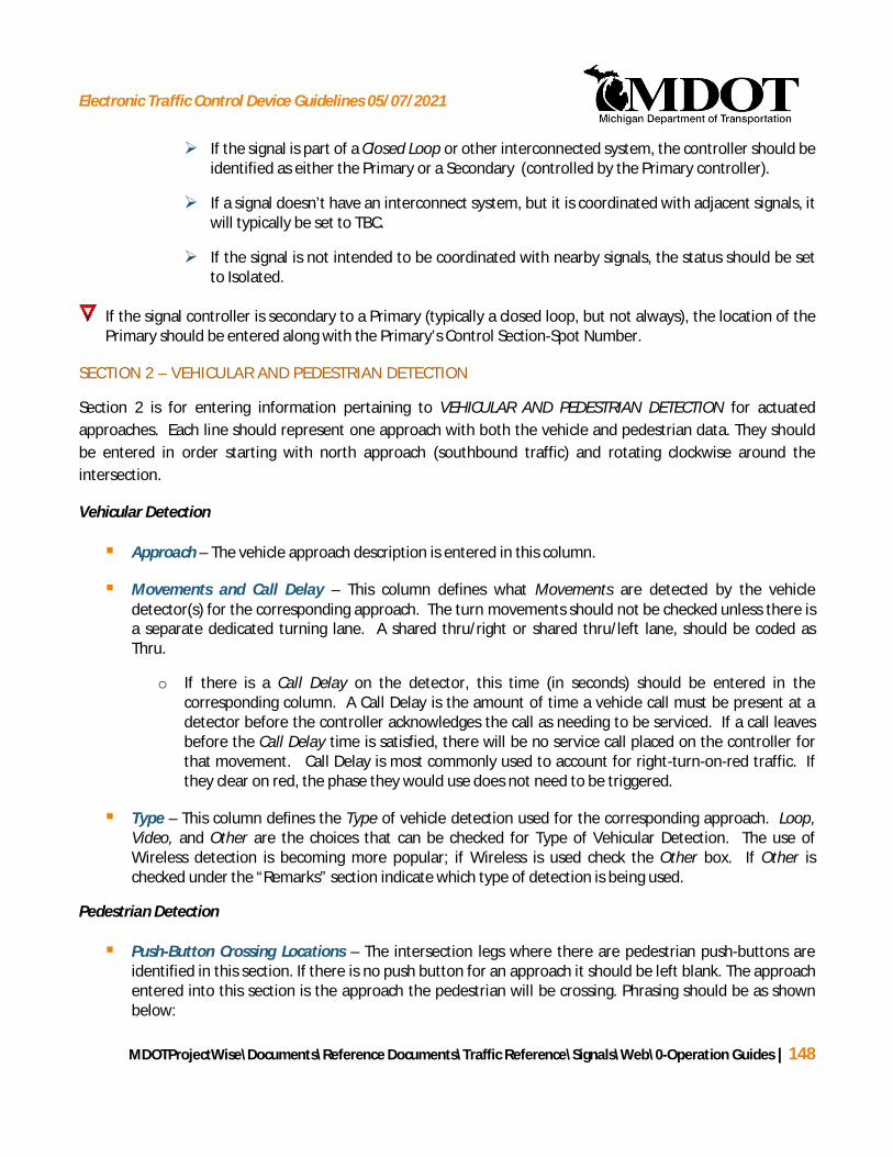
Electronic Traffic Control Device Guidelines 05/07/2021
MDOTProjectWise\Documents\Reference Documents\Traffic Reference\Signals\Web\0-Operation Guides | 148
Ø If the signal is part of a Closed Loop or other interconnected system, the controller should beidentified as either the Primary or a Secondary (controlled by the Primary controller).
Ø If a signal doesn’t have an interconnect system, but it is coordinated with adjacent signals, itwill typically be set to TBC.
Ø If the signal is not intended to be coordinated with nearby signals, the status should be setto Isolated.
If the signal controller is secondary to a Primary (typically a closed loop, but not always), the location of thePrimary should be entered along with the Primary’s Control Section-Spot Number.
SECTION 2 – VEHICULAR AND PEDESTRIAN DETECTION
Section 2 is for entering information pertaining to VEHICULAR AND PEDESTRIAN DETECTION for actuatedapproaches. Each line should represent one approach with both the vehicle and pedestrian data. They shouldbe entered in order starting with north approach (southbound traffic) and rotating clockwise around theintersection.
Vehicular Detection
§ Approach – The vehicle approach description is entered in this column.
§ Movements and Call Delay – This column defines what Movements are detected by the vehicledetector(s) for the corresponding approach. The turn movements should not be checked unless there isa separate dedicated turning lane. A shared thru/right or shared thru/left lane, should be coded asThru.
o If there is a Call Delay on the detector, this time (in seconds) should be entered in thecorresponding column. A Call Delay is the amount of time a vehicle call must be present at adetector before the controller acknowledges the call as needing to be serviced. If a call leavesbefore the Call Delay time is satisfied, there will be no service call placed on the controller forthat movement. Call Delay is most commonly used to account for right-turn-on-red traffic. Ifthey clear on red, the phase they would use does not need to be triggered.
§ Type – This column defines the Type of vehicle detection used for the corresponding approach. Loop,Video, and Other are the choices that can be checked for Type of Vehicular Detection. The use ofWireless detection is becoming more popular; if Wireless is used check the Other box. If Other ischecked under the “Remarks” section indicate which type of detection is being used.
Pedestrian Detection
§ Push-Button Crossing Locations – The intersection legs where there are pedestrian push-buttons areidentified in this section. If there is no push button for an approach it should be left blank. The approachentered into this section is the approach the pedestrian will be crossing. Phrasing should be as shownbelow:
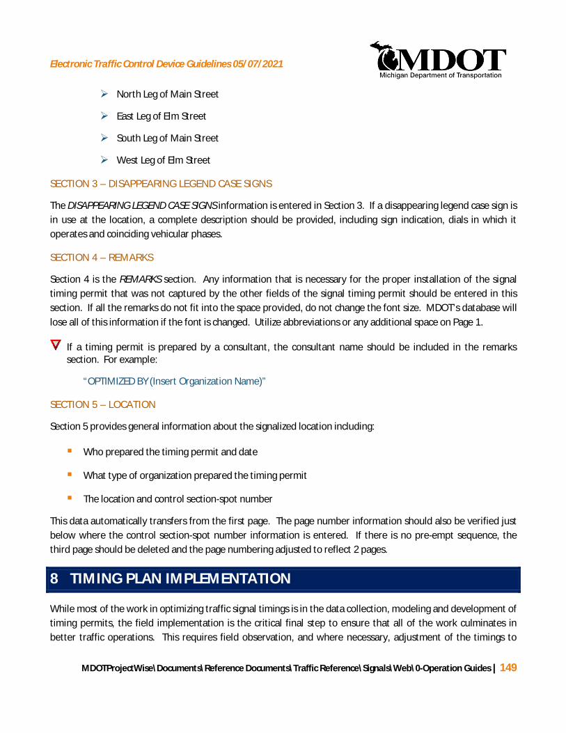
Electronic Traffic Control Device Guidelines 05/07/2021
MDOTProjectWise\Documents\Reference Documents\Traffic Reference\Signals\Web\0-Operation Guides | 149
Ø North Leg of Main Street
Ø East Leg of Elm Street
Ø South Leg of Main Street
Ø West Leg of Elm Street
SECTION 3 – DISAPPEARING LEGEND CASE SIGNS
The DISAPPEARING LEGEND CASE SIGNS information is entered in Section 3. If a disappearing legend case sign isin use at the location, a complete description should be provided, including sign indication, dials in which itoperates and coinciding vehicular phases.
SECTION 4 – REMARKS
Section 4 is the REMARKS section. Any information that is necessary for the proper installation of the signaltiming permit that was not captured by the other fields of the signal timing permit should be entered in thissection. If all the remarks do not fit into the space provided, do not change the font size. MDOT’s database willlose all of this information if the font is changed. Utilize abbreviations or any additional space on Page 1.
If a timing permit is prepared by a consultant, the consultant name should be included in the remarkssection. For example:
“OPTIMIZED BY (Insert Organization Name)”
SECTION 5 – LOCATION
Section 5 provides general information about the signalized location including:
§ Who prepared the timing permit and date
§ What type of organization prepared the timing permit
§ The location and control section-spot number
This data automatically transfers from the first page. The page number information should also be verified justbelow where the control section-spot number information is entered. If there is no pre-empt sequence, thethird page should be deleted and the page numbering adjusted to reflect 2 pages.
8 TIMING PLAN IMPLEMENTATION
While most of the work in optimizing traffic signal timings is in the data collection, modeling and development oftiming permits, the field implementation is the critical final step to ensure that all of the work culminates inbetter traffic operations. This requires field observation, and where necessary, adjustment of the timings to

Electronic Traffic Control Device Guidelines 05/07/2021
MDOTProjectWise\Documents\Reference Documents\Traffic Reference\Signals\Web\0-Operation Guides | 150
improve operations relative to actual traffic conditions. Timing changes are to be made by MDOT electrician ordesignated maintaining agent only.
8.1 FIELD ADJUSTMENTS
A field review of implemented timings is required for all projects in order to assure that timings have beenimplemented properly, and that the signal timings are facilitating traffic as they were designed. The field reviewof implemented timings should include the following steps:
§ Coordinate date of field implementation with MDOT signal operations engineer and MDOT electrician ordesignated maintaining agent.
§ Verification that individual signal controller clocks are synchronized.
§ Verification of offsets should be conducted by performing a driving check of the corridor to verifyprogression.
§ Any observed and unexpected conditions, such as cycle failures, extensive queuing or spillbacks, shouldbe noted and further reviewed to determine whether reallocation of green time is required orappropriate.
§ The speed and platooning of vehicles should be critically reviewed to determine whether progression ismaintained as intended, and whether adjustments should be made to better facilitate coordinatedtraffic flow.
Any recommended adjustments after implementation should be documented in a brief memo, along withupdated signal timing permits reflecting the proposed adjustments.
Outside of optimization projects, it is sometimes necessary to make on the spot minor changes in the trafficsignal timing. This may be due to construction activities, special events or changes in traffic patterns. It isimperative that any changes be recorded and a copy provided to the MDOT Signals Unit. Timing changesinitiated in the field must be compatible with the signal system. If time allows, the change should be reviewedby the MDOT Signals Unit prior to implementing the change. If an immediate response is required, the changesshould be done under the guidance of the MDOT Region/TSC Traffic and Safety Representative withdocumented changes provided to the MDOT Signals Unit after the fact.
Prior to any adjustments, the location should be thoroughly reviewed in the field. Particular attention should bepaid to the times when a problem may exist. Any changes should be implemented by the Region/TSC electricianor the maintaining agency.

Electronic Traffic Control Device Guidelines 05/07/2021
MDOTProjectWise\Documents\Reference Documents\Traffic Reference\Signals\Web\0-Operation Guides | 151
8.2 VERIFICATION THAT SIGNAL TIMING HAS BEEN INSTALLED
Traffic Signal Timing Permits are issued with one copy placed in the controller cabinet for ready reference. Asecond copy is kept in the Region/TSC Traffic and Safety files. A third copy is kept in the Lansing Traffic Signalspot files.
When new timing (or a timing modification) is installed in a controller, the MDOT electrician or maintainingagent shall create an electronic file of the controller’s all data report and email it to the MDOT Signals Unit.
If applicable, the Region/TSC electrician or maintaining agent shall also complete form 1577 “Traffic SignalTiming Record” including an explanation of any timing changes and why they were made (see Figure 8-1).
Figure 8-1: Traffic Signal Timing Record
This form is available on MDOT’s internal intranet service. Choose “MDOT’S Forms Services” under Quick Picks.Enter form number 1577.
The electrician will email this form along with the electronic file of the controller’s all data report to the MDOTSignals Unit to notify them when final timing is installed. MDOT Signals Unit will record the date in the timingpermit data base.

Electronic Traffic Control Device Guidelines 05/07/2021
MDOTProjectWise\Documents\Reference Documents\Traffic Reference\Signals\Web\0-Operation Guides
APPENDIX AMDOT Traffic Volume
Data Submittal Format

Electronic Traffic Control Device Guidelines 05/07/2021
MDOTProjectWise\Documents\Reference Documents\Traffic Reference\Signals\Web\0-Operation Guides
MDOT Traffic Volume Data Submittal Format
The following are guidelines for the submittal of traffic volume data (manual and machine counts) toMDOT for signal optimization projects:
§ File Format - All manual and machine counts should be exported into a Microsoft Excel format(.xls).
§ File Name – The file name will be the Control Section/Spot # followed by the date of the manualtraffic count. The following is an example:
77091-01-012_Jan27-2005_Counts.xls
§ Worksheet Arrangement – The Excel file will contain one worksheet for the manual trafficcounts, and separate worksheets for each of the machine counts with the worksheet tabsnamed accordingly (NB Machine Counts, SB Machine Counts, etc.).
§ Manual Traffic Counts General Info – The manual traffic counts worksheet will contain thefollowing info at the top of the worksheet:
Control Section/Spot #Ø Location (the MDOT name for the intersection)Ø City/TownshipØ Date (the date the manual traffic count was collected)Ø Weather (weather conditions if applicable)Ø Collected By (a note about who collected the counts)
Example:
Control Section/Spot # 77091-01-012
Location: M-25 Pine Grove at Hancock
City/Twp: Port Huron
Date: 1/27/2005 (Thursday)
Weather Clear, Dry 20 Deg's
Collected By: MDOT

Electronic Traffic Control Device Guidelines 05/07/2021
MDOTProjectWise\Documents\Reference Documents\Traffic Reference\Signals\Web\0-Operation Guides
§ Machine Counts General Info – The machine counts worksheet(s) will contain the following infoat the top of the worksheet:Ø Type of Count (direction of count taken and any pertinent information)Ø Location (where on the roadway was the count taken)Ø City/TownshipØ Start Date (date the machine count was started)Ø Collected By (a note about who collected the counts)
Example:
Type of Count: NB M-25 24-Hour Vehicle Count
Location: M-25 (210' South of Hancock St.)
City/Twp: Port Huron
Start Date: 2/1/2005 (Tuesday)
Collected By: MDOT
§ Offset Intersections – If the offset intersections are on the same controller, the counts should besummarized in one Excel file. If the offset intersections are on separate controllers, the countsshould be summarized in separate Excel files.
§ Multi-Approach Intersections – There will occasionally be situations where there are more than fourapproaches at an intersection. On the Manual Counts worksheet, simply add these additionalapproaches to the right of usual four approaches and label accordingly. For the machine counts,insert additional worksheets and name accordingly for the additional approaches.
§ Boulevard Intersections – Boulevard roadway intersections are to be treated as one intersection andsummarized in one Excel file. Crossovers adjacent to the boulevard intersection are to besummarized in separate Excel files (a different file for each crossover).
§ Closely Spaced Intersections – For closely spaced intersections, such as those near highway on/offramps, locations that are on the same controller should be summarized in the same Excel file. Caremust be taken in the naming of the Manual Count approaches and Machine Count locations so thatit is easily understood what approach is being described.

Electronic Traffic Control Device Guidelines 05/07/2021
MDOTProjectWise\Documents\Reference Documents\Traffic Reference\Signals\Web\0-Operation Guides
Sample Turning Movement Count Submittal Format
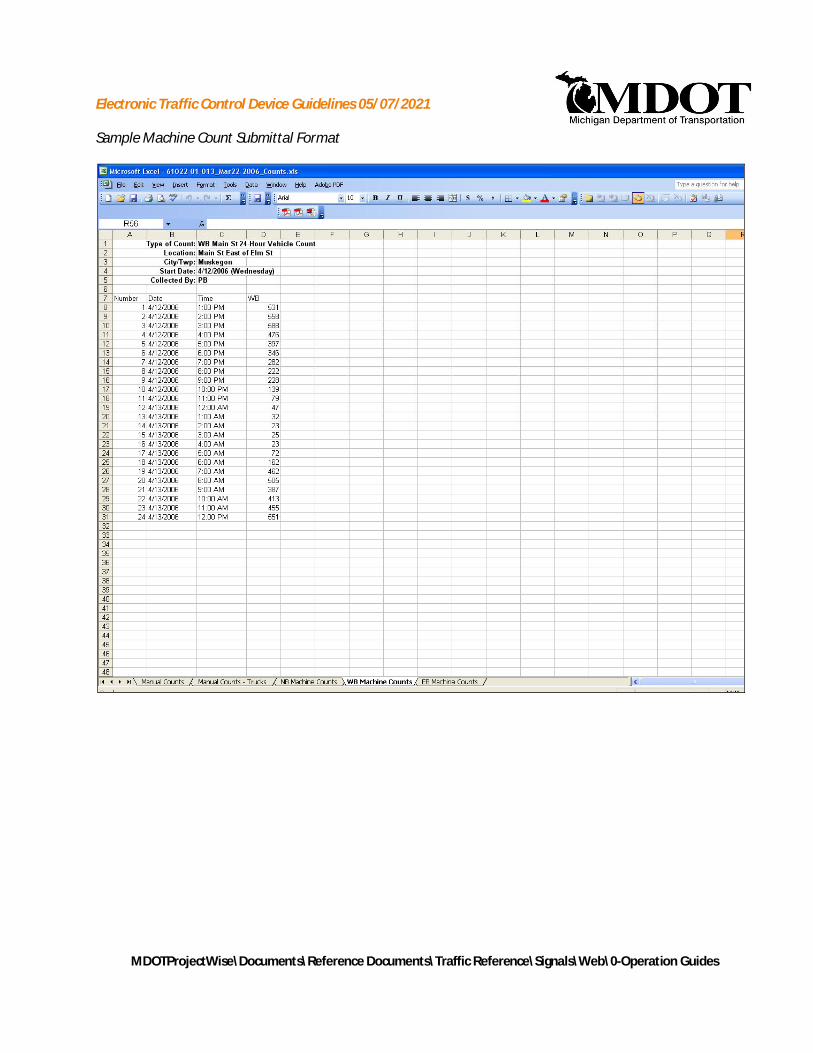
Electronic Traffic Control Device Guidelines 05/07/2021
MDOTProjectWise\Documents\Reference Documents\Traffic Reference\Signals\Web\0-Operation Guides
Sample Machine Count Submittal Format

Electronic Traffic Control Device Guidelines 05/07/2021
MDOTProjectWise\Documents\Reference Documents\Traffic Reference\Signals\Web\0-Operation Guides
APPENDIX BINTERSECTION INVENTORY AND
CONDITION FORM

Electronic Traffic Control Device Guidelines 05/07/2021
MDOTProjectWise\Documents\Reference Documents\Traffic Reference\Signals\Web\0-Operation Guides
MDOT Inventory Form
The following are guidelines for the data collection of intersection geometry and equipment as relatedto MDOT signal optimization projects. The two-pages of the Intersection Inventory and Condition Formare illustrated next, with a detailed description of the information filled into each section following.

Electronic Traffic Control Device Guidelines 05/07/2021
MDOTProjectWise\Documents\Reference Documents\Traffic Reference\Signals\Web\0-Operation Guides
AB
C
D
E

Electronic Traffic Control Device Guidelines 05/07/2021
MDOTProjectWise\Documents\Reference Documents\Traffic Reference\Signals\Web\0-Operation Guides
F
I
H
G

Electronic Traffic Control Device Guidelines 05/07/2021
MDOTProjectWise\Documents\Reference Documents\Traffic Reference\Signals\Web\0-Operation Guides
Section A – Intersection Location and Number
Section A provides the general information about the intersections location including:
§ Main and Cross Street Name
§ City/Township, County
§ Latitude & Longitude Coordinates: the coordinates should be as close to the center of where theroads cross as possible. For Boulevards it should be the center of the combined intersection. Thestandard format should be as shown (Latitude/Longitude) and the last two digits should bedecimals. Utilization of Google Earth is acceptable for obtaining the coordinates. If an existinginventory form is available and includes the GPS coordinates they should not be changed unlessa review shows them to be incorrect.
Example: DD-MM-SS.SS
§ Intersection Number and Mile Post Number. These are the Control Section, Spot number andMile Post number provided by MDOT.
§ Prime Number
§ MDOT Project Number
§ The observer who performed the inventory and the date in which it was completed on shouldalso be entered.
Section B – Street Naming
Section B provides the names for each approach as indicated by the direction above. If there is noapproach in a particular direction, leave this street name blank.
Section C – Geometry
Section C provides information regarding approach lanes, intersection measurements, parking lanes,and grades.
§ Through Lanes: The number of through lanes present in each direction.
§ Left and Right Turn Lanes: Indicates the number of right and left turn lanes and theircorresponding lengths. If a turn lane is shared with a through lane movement, count it as athrough lane. If a two-way left-turn lane (TWLTL) is present, indicate this on the inventoryform using the abbreviation TWLTL next to the left turn lane. In Synchro this length should becoded as a TWLTL with a 500 foot storage length unless a field review shows that asunreasonable (ie: queuing observed to be longer than 500 feet or it would extend back beyonda major intersection limiting drivers ability to utilize a full 500 feet).

Electronic Traffic Control Device Guidelines 05/07/2021
MDOTProjectWise\Documents\Reference Documents\Traffic Reference\Signals\Web\0-Operation Guides
Ø If adjacent parking is present and ends before the intersection, thus leaving room for avehicle to make a right turn, indicate this as an available right turn lane, with storagedistance. Observations should be made to determine if traffic is utilizing this space as aright turn lane. Include a note in the comments section indicating this is the case. Ifthe parking ends at the intersection, as can be seen in Figure 1 on the southboundapproach, then there is no exclusive right turn lane.
Ø Turn lane lengths should be measured based on the length of full width pavement, notwhere the pavement markings stop. If congestion is significant, part of the taperlength may be coded as storage. If this is done a remark should be included in thecomments section that the operation was being used based on field observation.
Ø Some approaches will be marked as a single lane but may be wide enough toaccommodate multiple lanes of traffic. In this case the operation should be observedand the lanes shown as they function along with a note in the comments sectionexplaining this.
§ Intersection Width: See Section 4.1 for details on measuring intersection widths. If it is aboulevard the near/far stop bar distance should be entered in parentheses after theintersection width.
§ Pedestrian Crossing Length / Button Distance: See Section 4.2 for details on measuring thepedestrian crossing length. The first and third entry for each approach are the distances fromthe curb to the pushbuttons, if present. The middle entry is the actual crossing distance. This ismost helpful when reducing the walk time from 7.0 sec to 4.0 sec, if this distance is more thanthe recommended 10 feet and the pedestrian waits near the push button and not the curb, thewalk time should be increased.
§ Adjacent Parking Lane Approach and Departure: Indicates with a yes, “Y”, or a no, “N”whether a parking lane is present. If a parking lane is present on the near side of theintersection this would be labeled as an Approach Parking Lane, whereas if the parking lane islocated on the far side of the intersection it should be labeled as a Departure Parking Lane.
Ø See Figure 1 for a visual. There is parking available on Main Street only. For thenorthbound lane Approach Parking should be indicated, whereas for the southboundlane both Approach and Departure Parking should be indicated.
§ Approach Grade: Grades are indicated as either positive or negative. If the approach is uphillthis would be positive, if the approach is downhill it would be negative. A visual estimate ofthe grade should be entered on the inventory form. For any grade perceived as 2% or less,leave as 0% on the clearance interval calculation spreadsheet (Section 4.1). For any gradeperceived as 3% or higher, enter these values on the clearance interval calculationspreadsheet. Also note the grades in the REMARKS section of the timing permit. (i.e. EB M-55approach grade 5%). Leave all grades out of the Synchro files.
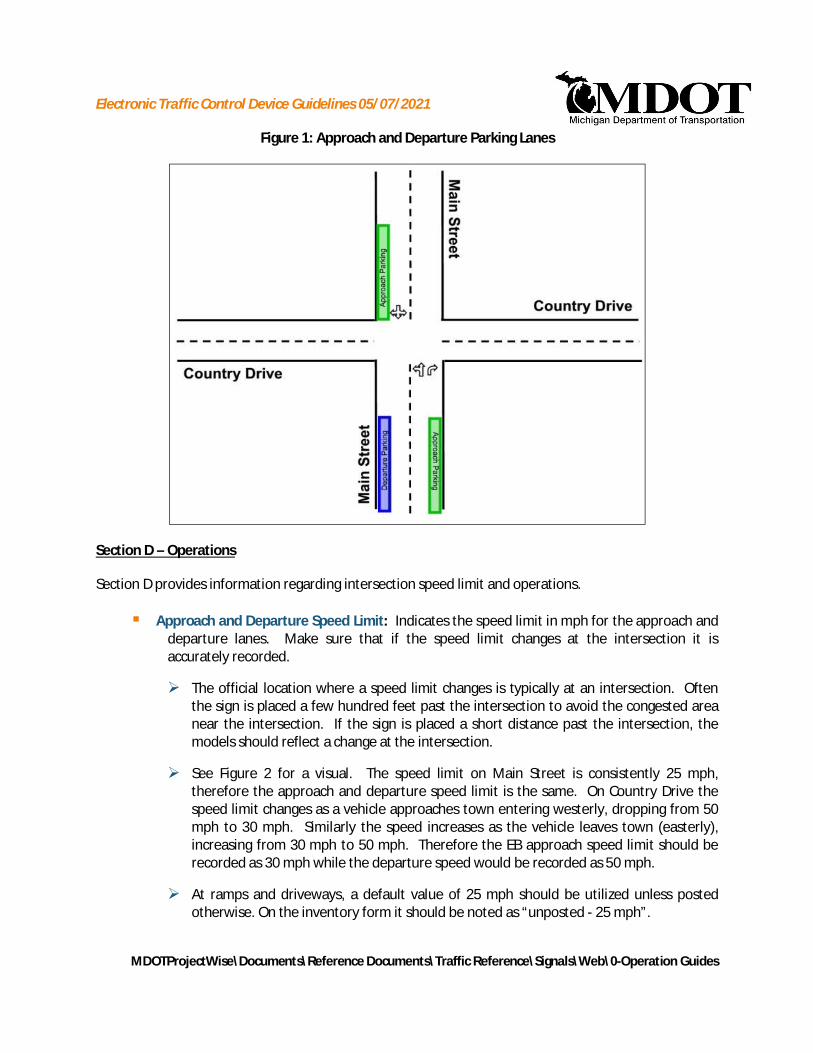
Electronic Traffic Control Device Guidelines 05/07/2021
MDOTProjectWise\Documents\Reference Documents\Traffic Reference\Signals\Web\0-Operation Guides
Figure 1: Approach and Departure Parking Lanes
Section D – Operations
Section D provides information regarding intersection speed limit and operations.
§ Approach and Departure Speed Limit: Indicates the speed limit in mph for the approach anddeparture lanes. Make sure that if the speed limit changes at the intersection it isaccurately recorded.
Ø The official location where a speed limit changes is typically at an intersection. Oftenthe sign is placed a few hundred feet past the intersection to avoid the congested areanear the intersection. If the sign is placed a short distance past the intersection, themodels should reflect a change at the intersection.
Ø See Figure 2 for a visual. The speed limit on Main Street is consistently 25 mph,therefore the approach and departure speed limit is the same. On Country Drive thespeed limit changes as a vehicle approaches town entering westerly, dropping from 50mph to 30 mph. Similarly the speed increases as the vehicle leaves town (easterly),increasing from 30 mph to 50 mph. Therefore the EB approach speed limit should berecorded as 30 mph while the departure speed would be recorded as 50 mph.
Ø At ramps and driveways, a default value of 25 mph should be utilized unless postedotherwise. On the inventory form it should be noted as “unposted - 25 mph”.
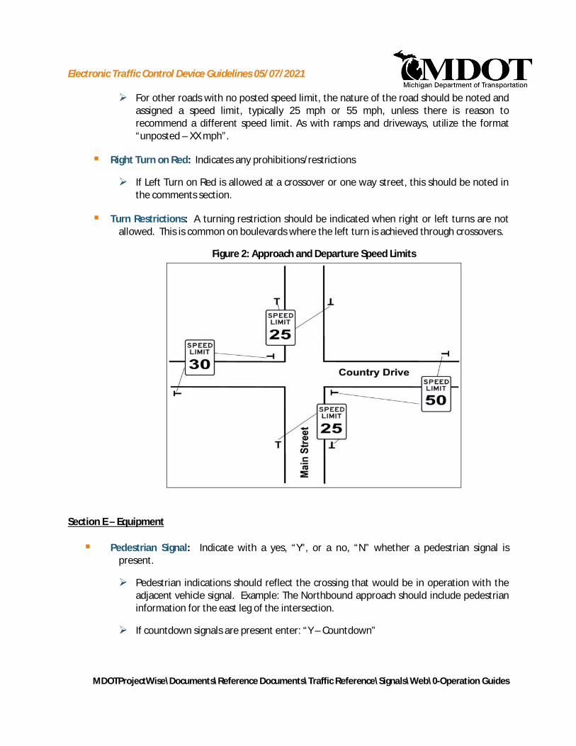
Electronic Traffic Control Device Guidelines 05/07/2021
MDOTProjectWise\Documents\Reference Documents\Traffic Reference\Signals\Web\0-Operation Guides
Ø For other roads with no posted speed limit, the nature of the road should be noted andassigned a speed limit, typically 25 mph or 55 mph, unless there is reason torecommend a different speed limit. As with ramps and driveways, utilize the format“unposted – XX mph”.
§ Right Turn on Red: Indicates any prohibitions/restrictions
Ø If Left Turn on Red is allowed at a crossover or one way street, this should be noted inthe comments section.
§ Turn Restrictions: A turning restriction should be indicated when right or left turns are notallowed. This is common on boulevards where the left turn is achieved through crossovers.
Figure 2: Approach and Departure Speed Limits
Section E – Equipment
§ Pedestrian Signal: Indicate with a yes, “Y”, or a no, “N” whether a pedestrian signal ispresent.
Ø Pedestrian indications should reflect the crossing that would be in operation with theadjacent vehicle signal. Example: The Northbound approach should include pedestrianinformation for the east leg of the intersection.
Ø If countdown signals are present enter: “Y – Countdown”

Electronic Traffic Control Device Guidelines 05/07/2021
MDOTProjectWise\Documents\Reference Documents\Traffic Reference\Signals\Web\0-Operation Guides
§ Pedestrian Push Button: Indicate with a yes, “Y”, or a no, “N” whether a push button ispresent.
§ Left Turn Head Type: The left turn signal head type should be indicated as:
Ø 3 - Level Arrow
Ø 4 - Level Green Arrow
Ø 4 - Level Yellow Arrow Flash
Ø Dog-House
§ Right Turn Green Arrow: Indicates with a yes, “Y”, or a no, “N” whether a right turn greenarrow is present.
§ Ambient Light: MDOT is moving away from internally lighted case signs if there is ambientlighting within the area. Ambient lighting can be provided from an overhead streetlight orfrom an adjacent parking lot. Any reasonable amount of lighting should be coded as yes.This is a judgment determination. A separate night review is not required.
Section F – Signal Phasing
Section F provides a drawing of each phase for which the signal operates. A solid line indicates that themovement is “Protected”, a dashed line indicates that the movement is “Permitted”. Provided in eachof the phases are four arrows:
§ Permitted Left Arrow
§ Protected Left Arrow
§ Protected Through Arrow
§ Protected Right Arrow: The protected right turn should only be checked if there is a right turnarrow and it is on during that phase.
For each phase, indicate which movements are allowed, leaving blank those movements that are notstopped. In the case where a signal has more than six phases attach a third page and provide anexplanation in the general comments section (I).
For T intersections for the movement coming from the bottom of the T, the through movement shouldbe checked if there are no turn arrows. If there are green arrows, the turning movements should bechecked. This is primarily to differentiate between a protected turning movement and one with thepotential for conflicting pedestrians.

Electronic Traffic Control Device Guidelines 05/07/2021
MDOTProjectWise\Documents\Reference Documents\Traffic Reference\Signals\Web\0-Operation Guides
Section G – Intersection Layout Diagram
In the space provided for drawing, a clean hand sketch or an electronic version of the intersectionshould be provided. Data to be included are as follows:
§ Through Lanes§ Turn Lanes§ Width/Measurements§ Crosswalk Length§ Parking Lanes§ Bus Stops
§ Signal Poles§ Pedestrian Signal/Push Button§ Controller§ Detection§ Signal Head Direction§ Directional North Arrow: to be indicated
via radio button.
To add an electronic version of the intersection layout start by left-clicking anywhere within the gridded-box area. This will bring up a “Select Image File” box. From here route the browser to the correct imagefile. Click on intersection layout and choose “Select,” this will add the layout to the Inventory form.
Section I – General Comments
Section I provides extra space for anything that is not contained within the Inventory form. A possibleitem to include is if the layout should be modeled differently in Synchro than from what is shown. Thiscase is most common when an approach lane is marked as a single lane but is wide enough that it isbeing used as two approach lanes.
Section H – Intersection Location and Number
The information contained within Section H carries over from Page 1 when inserted.

Electronic Traffic Control Device Guidelines 05/07/2021
MDOTProjectWise\Documents\Reference Documents\Traffic Reference\Signals\Web\0-Operation Guides
APPENDIX CSAMPLE TIMING PERMIT FORMS
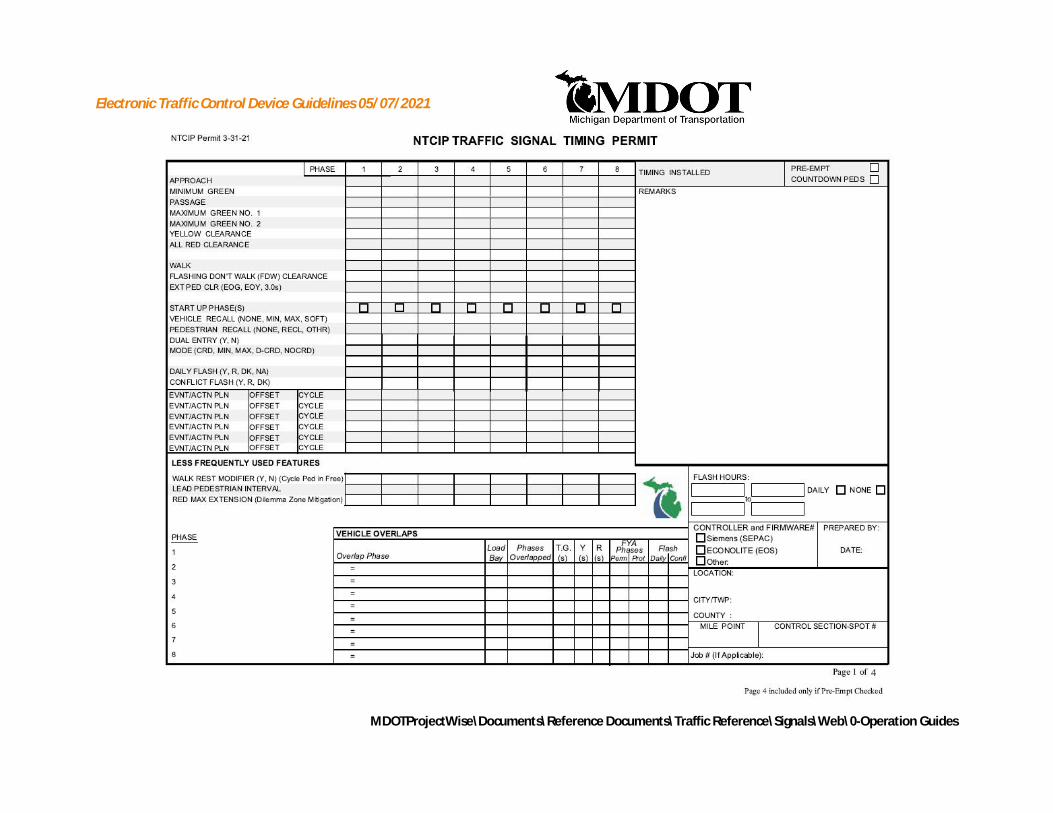
Electronic Traffic Control Device Guidelines 05/07/2021
MDOTProjectWise\Documents\Reference Documents\Traffic Reference\Signals\Web\0-Operation Guides

Electronic Traffic Control Device Guidelines 05/07/2021
MDOTProjectWise\Documents\Reference Documents\Traffic Reference\Signals\Web\0-Operation Guides

Electronic Traffic Control Device Guidelines 05/07/2021
MDOTProjectWise\Documents\Reference Documents\Traffic Reference\Signals\Web\0-Operation Guides

Electronic Traffic Control Device Guidelines 05/07/2021
MDOTProjectWise\Documents\Reference Documents\Traffic Reference\Signals\Web\0-Operation Guides

Electronic Traffic Control Device Guidelines 05/07/2021
MDOTProjectWise\Documents\Reference Documents\Traffic Reference\Signals\Web\0-Operation Guides
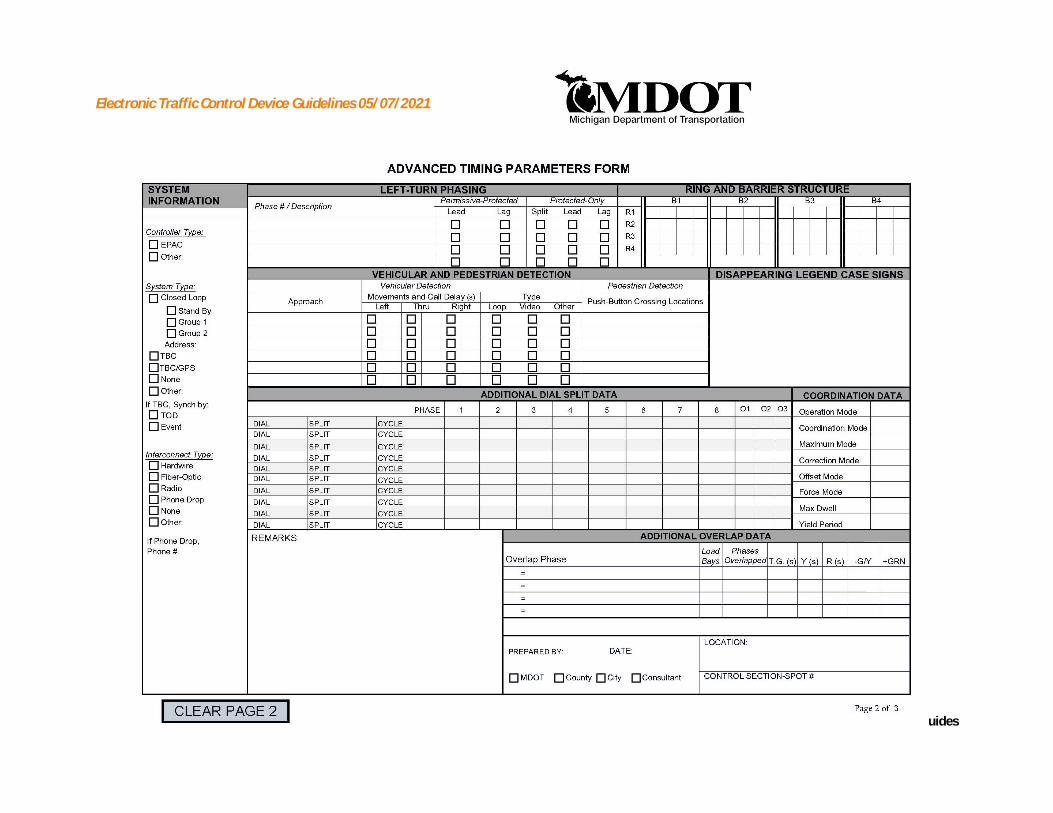
Electronic Traffic Control Device Guidelines 05/07/2021
MDOTProjectWise\Documents\Reference Documents\Traffic Reference\Signals\Web\0-Operation Guides

Electronic Traffic Control Device Guidelines 05/07/2021
MDOTProjectWise\Documents\Reference Documents\Traffic Reference\Signals\Web\0-Operation Guides

Electronic Traffic Control Device Guidelines 05/07/2021
MDOTProjectWise\Documents\Reference Documents\Traffic Reference\Signals\Web\0-Operation Guides

Electronic Traffic Control Device Guidelines 05/07/2021
MDOTProjectWise\Documents\Reference Documents\Traffic Reference\Signals\Web\0-Operation Guides

Electronic Traffic Control Device Guidelines 05/07/2021
MDOTProjectWise\Documents\Reference Documents\Traffic Reference\Signals\Web\0-Operation Guides

Electronic Traffic Control Device Guidelines 05/07/2021
MDOTProjectWise\Documents\Reference Documents\Traffic Reference\Signals\Web\0-Operation Guides
APPENDIX DSYNCHRO AND SIMTRAFFIC
SAMPLE ANALYSIS REPORT FORMATS

Electronic Traffic Control Device Guidelines 05/07/2021
MDOTProjectWise\Documents\Reference Documents\Traffic Reference\Signals\Web\0-Operation Guides
Sample SYNCHRO HCM Analysis Report Format
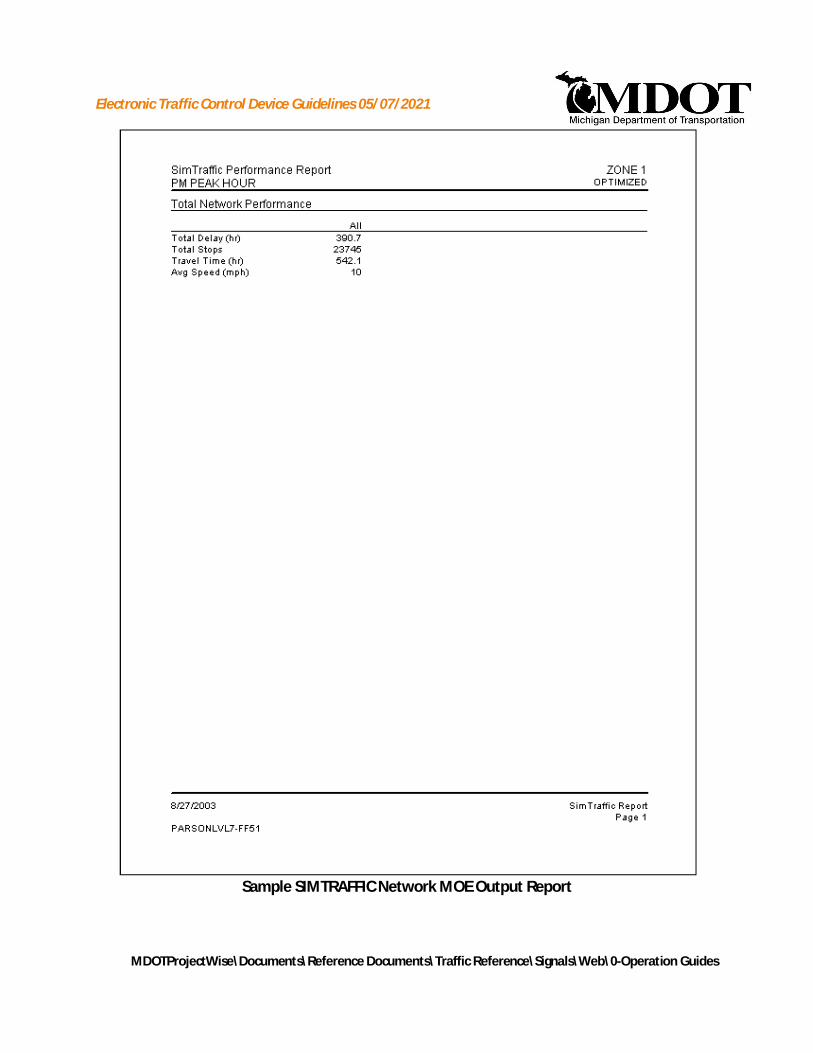
Electronic Traffic Control Device Guidelines 05/07/2021
MDOTProjectWise\Documents\Reference Documents\Traffic Reference\Signals\Web\0-Operation Guides
Sample SIMTRAFFIC Network MOE Output Report

Electronic Traffic Control Device Guidelines 05/07/2021
MDOTProjectWise\Documents\Reference Documents\Traffic Reference\Signals\Web\0-Operation Guides
Sample SYNCHRO 90th percentile flow diagram
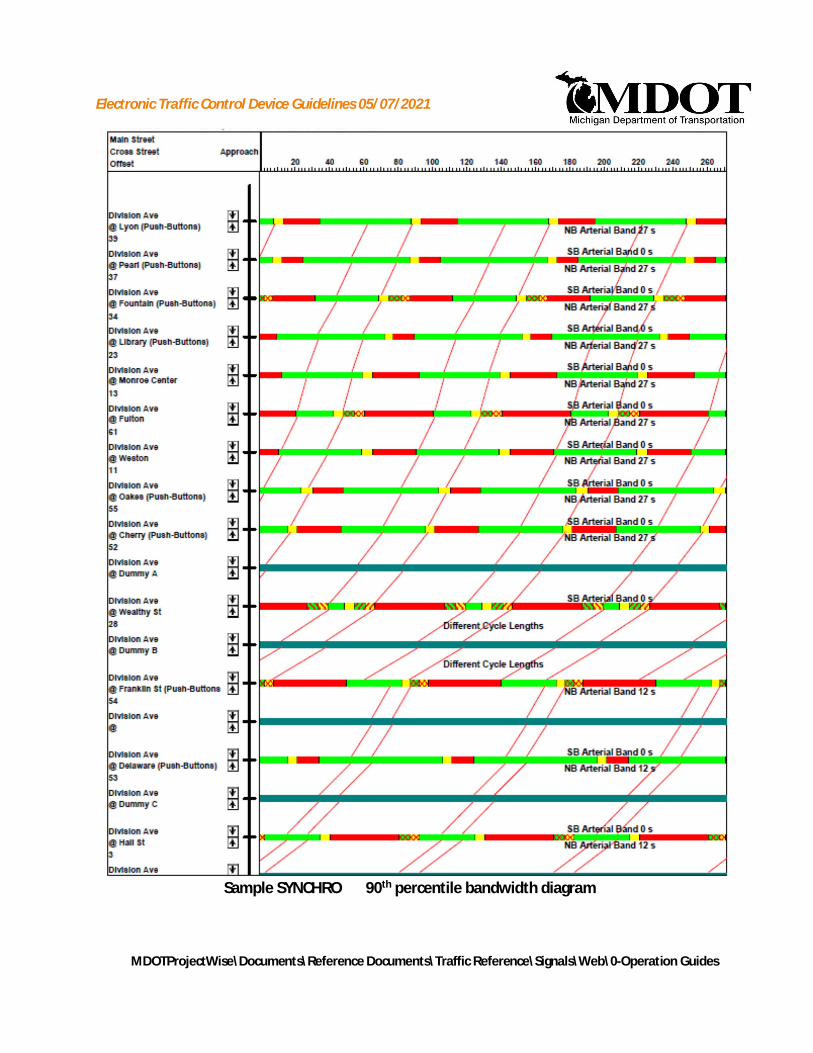
Electronic Traffic Control Device Guidelines 05/07/2021
MDOTProjectWise\Documents\Reference Documents\Traffic Reference\Signals\Web\0-Operation Guides
Sample SYNCHRO 90th percentile bandwidth diagram

Electronic Traffic Control Device Guidelines 05/07/2021
MDOTProjectWise\Documents\Reference Documents\Traffic Reference\Signals\Web\0-Operation Guides
APPENDIX ESAMPLE BENEFIT COST ANALYSIS
SPREADSHEET

Electronic Traffic Control Device Guidelines 05/07/2021
MDOTProjectWise\Documents\Reference Documents\Traffic Reference\Signals\Web\0-Operation Guides

Electronic Traffic Control Device Guidelines 05/07/2021
MDOTProjectWise\Documents\Reference Documents\Traffic Reference\Signals\Web\0-Operation Guides