electronic warfare self-protection of battlefield ...checksix-fr.com/downloads/dcs/docs/electronic...
TRANSCRIPT

Helsinki University of Technology, Applied Electronics Laboratory Series E: Electronics Publications E18 Teknillisen korkeakoulun sovelletun elektroniikan laboratorion julkaisusarja E: Elektronisia julkaisuja E18 Espoo 2005 ELECTRONIC WARFARE SELF-PROTECTION OF BATTLEFIELD HELICOPTERS: A HOLISTIC VIEW Johnny Heikell
Dissertation for the degree of Doctor of Science in Technology to be presented with due permission of the Department of Electrical and Communications Engineering, Helsinki University of Technology, for public examination and debate in Auditorium S4 at Helsinki University of Technology (Espoo, Finland) on the 24 of March, 2005, at 12 noon. Helsinki University of Technology Department of Electrical and Communications Engineering Applied Electronics Laboratory Teknillinen korkeakoulu Sähkö- ja tietoliikennetekniikan osasto Sovelletun elektroniikan laboratorio

2
Distribution: Helsinki University of Technology Applied Electronics Laboratory P.O. Box 3000 FI-02015 TKK FINLAND Tel: +358-(0)9-451 2301 Fax: +358-(0)9-451 2307 http://www.hut.fi/Units/Electronics/ Online in PDF format: http://lib.hut.fi/Diss/2005/isbn9512275465/ E-mail: [email protected] © Johnny Heikell ISBN 951-22-7545-7 (printed) ISBN 951-22-7546-5 (PDF) ISSN 1459-1111 Otamedia Oy Espoo 2005

3
HELSINKI UNIVERSITY OF TECHNOLOGY ABSTRACT OF THE DOCTORAL DISSERTATION Author: Johnny Heikell
ELECTRONIC WARFARE SELF-PROTECTION OF BATTLEFIELD HELICOPTERS: A HOLISTIC VIEW Date: 14.2.2005 Number of Pages: 217 Department of Electrical and Communications Engineering
Professorship: S-66 Applied Electronics Supervisor: Professor Raimo Sepponen
Instructor: N.N. The dissertation seeks to increase understanding of electronic warfare (EW) self-protection (EWSP) of battlefield helicopters by taking a holistic (systems) view on EWSP. It also evaluates the methodologies used in the research and their suitability as descriptive tools in communication between various EWSP stakeholders. The interpretation of the term “holistic view” is a central theme to the dissertation. The research methodology is bottom-up—which is necessary since no previous work exists that could guide the study—and progresses from analysis to synthesis. Initially several methods are evaluated for presenting findings on EWSP, including high-level system simulation such as Forrester system dynamics (FSD). The analysis is conducted by a comprehensive literature review on EW and other areas that are believed to be of importance to the holistic view. Combat scenarios, intelligence, EW support, validation, training, and delays have major influence on the effectiveness of the EWSP suite; while the initial procurement decision on the EWSP suite sets limits to what can be achieved later. The need for a vast support structure for EWSP means that countries with limited intelligence and other resources become dependent on allies for support; that is, the question of EWSP effectiveness becomes political. The synthesis shows that a holistic view on EWSP of battlefield helicopters cannot be bounded in the temporal or hierarchical (organizational) senses. FSD is found to be helpful as a quality assurance tool, but refinements are needed if FSD is to be useful as a general discussion tool. The area of survivability is found to be the best match for the holistic view—for an EWSP suprasystem. A global survivability paradigm is defined as the ultimate holistic view on EWSP. It is suggested that future research should be top-down and aiming at promoting the global survivability paradigm. The survivability paradigm would give EWSP a natural framework in which its merits can be assessed objectively. Keywords: electronic warfare, self-protection, battlefield helicopter, survivability, susceptibility reduction, systems engineering, systems thinking, system dynamics

4
TEKNISKA HÖGSKOLAN REFERAT AV DOKTORSAVHANDLINGEN Utfört av: Johnny Heikell
VARNINGS- OCH MOTMEDELSSYSTEM FÖR MILITÄRA HELIKOPTRAR: ETT HOLISTISKT PERSPEKTIV Datum: 14.2.2005 Sidoantal: 217 Avdelning: Elektro- och telekommunikationsteknik
Professur: S-66 Tillämpad elektronik Övervakare: Professor Raimo Sepponen
Handledare: N.N. Avhandlingen söker förbättra förståelsen för varnings- och motmedelssystem (VMS) för militära helikoptrar genom en holistisk (system-) syn på VMS-problematiken. Den evaluerar också de metoder som används i forskningen jämte deras användbarhet för kommunikation mellan olika VMS-intressegrupper. Tolkningen av begreppet ”holistiskt perspektiv” är ett centralt tema i avhandlingen. Forskningsmetodiken är bottom-up—vilket är nödvändigt eftersom det inte finns tidigare studier som kunde fungera som modell för arbetet—och går från analys till syntes. I inledningen evalueras några metoder för presentation av rön om VMS, inklusive högnivåsystemsimulation såsom Forresters systemdynamik (FSD). Analysen utförs som ett omfattande litteraturstudium inom området telekrig, samt inom andra områden som antas vara av betydelse för det holistiska perspektivet. Stridsscenarier, underrättelser, telekrigstöd, validering, utbildning, samt fördröjningar har en central betydelse för VMS-utrustningens effektivitet; medan de beslut som fattas i upphandlingsskedet sätter begränsningar för vad som kan åstadkommas senare. Behovet av ett stort stödsystem för VMS betyder att länder med begränsade underrättelse- och andra resurser blir beroende av allierade för stöd, vilket leder till att VMS-effektivitet får politiska konsekvenser. Syntesen visar att ett holistiskt perspektiv av VMS för militära helikoptrar inte kan begränsas i temporal eller hierarkisk (organisatorisk) mening. FSD befinnas vara av hjälp som ett kvalitetsredskap, men ytterligare utveckling krävs om FSD skall bli användbar som ett generellt diskussionsredskap. Överlevnadsförmåga är det område som bäst sammanfaller med idén om ett holistiskt perspektiv—ett VMS-suprasystem. Ett globalt överlevnads-paradigm bedöms vara den definitiva holistiska synen på VMS. Det rekommenderas att fortsatt forskning skall utföras top-down med strävan att vidareutveckla det globala överlevnadsparadigmet. Överlevnadsparadigmet skulle utgöra en naturlig hemvist för VMS, där dess meriter kan avvägas objektivt. Nyckelord: telekrig, varnings- och motmedelssystem, militär helikopter, överlevnad, reduktion av mottaglighet, systemteknik, systemtänkande, systemdynamik

5
PREFACE
Illis quorum meruere labores Propertius
Working on this dissertation for well over six years, I have mustered a deep sympathy for the following words by Raymond Aron: “(…) as Clausewitz repeatedly revises his treatise, he comes to a deeper understanding of his own ideas, but before his untimely death he brings fully developed insights to bear only upon the final revision of Chapter 1 of Book One (…)”. So much remains to be done, but if anything ever was to be published it had to be done so even with the feeling of dissatisfaction of an incomplete work. Although a doctoral dissertation is a very personal academic exertion, it is always the result of a community effort. Over the years I have received support from a great number of individuals and institutions, of whom the most critical are: Paavo Jääskeläinen, emeritus professor at Helsinki University of Technology, together with Sverre Slotte and Brita Kuula, retired instructors at Vasa Technical Institute. They helped me on the way to study radar engineering at the University of Kansas. My Jayhawk year was crucial for this work and I have fond memories of the Sunflower State, the city of Lawrence, and of KU. Lieutenant General (ret.) Heikki Tilander, my previous superior at the FDF Defense Staff (then Brigadier General), honored my wish to join the Army’s helicopter project—later the NSHP. Two years of discussions with colleagues, EW and helicopter manufacturers, and others during the NSHP program are deeply reflected in this work. Raimo Sepponen, professor Jääskeläinen’s successor, supervised the work and helped me in a major task by pinpointing the word “holistic”, and thus the title “Electronic warfare self-protection of battlefield helicopters, a holistic view” was born. The preliminary examiners of the dissertation were Dr Filippo Neri, VirtuaLabs s.r.l., Italy, and Dr Gustaf Olsson, FOI, Sweden. Their recommendation cleared the dissertation for publication. My wife Marianne was always supportive, even when the laptop was running although the house badly needed attention. I should of course not forget the role of my employer, the Finnish Defence Forces, who over the years has invested heavily in my training and supported this work. And finally a feeling of gratitude goes to the US Freedom of Information Act. My search for information has mostly turned up American sources—a good part of which are funded by the Pentagon. Without this policy of openness my dissertation would not have come true. To all those neither mentioned above nor acknowledged at the end of the text, I can only say: Thank you. Espoo 14 February 2005 Johnny Heikell

6

7
LIST OF CONTENTS Title page
Abstracts
Preface
List of contents
Symbols and abbreviations
1 INTRODUCTION ............................................................................................17
1.1 Incentive for the work ..................................................................................17
1.2 Present deficiencies.......................................................................................17 1.2.1 Opinions on EWSP......................................................................................................17 1.2.2 The position of other stakeholders .............................................................................19 1.2.3 The EWSP communication gap .................................................................................20 1.2.4 Change of attitude .......................................................................................................21
1.3 Objective of work..........................................................................................22 1.3.1 The problem and the need for a solution...................................................................22 1.3.2 Objectives of work.......................................................................................................23 1.3.3 Methodology ................................................................................................................25 1.3.4 Comments to the objectives ........................................................................................25
1.4 Overview of the present work......................................................................27 1.4.1 Information types, classification, and reliability ......................................................27 1.4.2 Tentative idea on information for the present work ................................................28 1.4.3 Specific and generic threat scenarios.........................................................................30 1.4.4 Organization of the present work ..............................................................................31
2 METHODOLOGY ...........................................................................................33
2.1 Introduction...................................................................................................33
2.2 Research method...........................................................................................33
2.3 Tools for analysis and synthesis...................................................................34 2.3.1 Quantitative vs. qualitative approaches ....................................................................34 2.3.2 Modeling vs. simulation ..............................................................................................35 2.3.3 Alternatives for further study ....................................................................................35 2.3.4 Traditional methods ....................................................................................................37 2.3.5 Word-and-arrow diagrams ........................................................................................37 2.3.6 Checkland’s soft system methodology .......................................................................39 2.3.7 Forrester system dynamics .........................................................................................40 2.3.8 Tools for mathematical computation.........................................................................42
2.4 Conclusions on methods ...............................................................................43

8
3 THE OPERATIONAL SETTING ..................................................................45
3.1 Helicopters and armed conflicts ..................................................................45 3.1.1 Development of battlefield helicopters ......................................................................45 3.1.2 Strengths of helicopters ..............................................................................................45 3.1.3 Weaknesses of helicopters ..........................................................................................46 3.1.4 Development trends.....................................................................................................46 3.1.5 Conclusions on helicopters .........................................................................................47
3.2 The battlefield ...............................................................................................47 3.2.1 Conflicts and threats ...................................................................................................47 3.2.2 Helicopter operations and tactics...............................................................................50 3.2.3 Conclusions and implications for EWSP...................................................................53
3.3 Survivability ..................................................................................................54 3.3.1 Review of survivability concepts ................................................................................54 3.3.2 Susceptibility................................................................................................................56 3.3.3 Additional considerations on survivability................................................................58 3.3.4 Conclusions and implications for EWSP...................................................................60
3.4 Phenomenology .............................................................................................61 3.4.1 Overview ......................................................................................................................61 3.4.2 Helicopter signatures ..................................................................................................62 3.4.3 Background signatures ...............................................................................................64 3.4.4 Threat signatures.........................................................................................................65 3.4.5 Summary of phenomenology ......................................................................................66
3.5 Conclusions on the operational setting .......................................................66
4 THREATS AND COUNTERMEASURES ....................................................67
4.1 Threat systems ..............................................................................................67 4.1.1 Overview ......................................................................................................................67 4.1.2 Non-terminal threat systems ......................................................................................68 4.1.3 Terminal threats: static systems ................................................................................69 4.1.4 Terminal threats: mobile systems ..............................................................................69
Small arms fire and RPGs.......................................................................................................69 Artillery and MBTs.................................................................................................................69 Anti-aircraft guns and SPAAGs..............................................................................................70 Missiles ...................................................................................................................................71 Aircraft rockets and guns........................................................................................................74 Directed energy weapons........................................................................................................74
4.1.5 Terminal threats: propagators and fuzes ..................................................................75 4.1.6 Threat system development trends ............................................................................75 4.1.7 Conclusions and implications for EWSP...................................................................76
4.2 Threat technology .........................................................................................77 4.2.1 Overview ......................................................................................................................77 4.2.2 EO sensors....................................................................................................................77
IR sensor and seeker technology.............................................................................................77 Laser technology and guidance...............................................................................................80
4.2.3 RF sensors ....................................................................................................................81 4.2.4 Threat timelines...........................................................................................................83 4.2.5 Threat technology development trends .....................................................................84 4.2.6 Opportunities for electronic countermeasures .........................................................85 4.2.7 Conclusions and implications for EWSP...................................................................86

9
4.3 EWSP countermeasure technology .............................................................86 4.3.1 The scope of EWSP countermeasure technology......................................................86 4.3.2 Warning system technology........................................................................................87
General requirements on warning systems .............................................................................87 Radar warning receivers .........................................................................................................87 Missile warning systems.........................................................................................................89 Laser warning receivers ..........................................................................................................90
4.3.3 Countermeasure technology .......................................................................................90 General requirements on countermeasures .............................................................................90 RF countermeasures................................................................................................................91 EO countermeasures ...............................................................................................................94
4.3.4 Warning and countermeasure development trends and issues ...............................97 4.3.5 Extended discussion on threats and countermeasures .............................................99 4.3.6 Conclusions on EWSP countermeasure technology .................................................99
4.4 Conclusions on threats and countermeasures..........................................100
5 EWSP SYSTEMS AND SUPPORT CONSIDERATIONS.........................101
5.1 Introduction.................................................................................................101
5.2 Support factors............................................................................................102 5.2.1 Support functions ......................................................................................................102
Intelligence ...........................................................................................................................102 EW support center ................................................................................................................104 Mission planning and execution ...........................................................................................105 The EWSP life cycle.............................................................................................................107
5.2.2 Aircrew factors ..........................................................................................................107 5.2.3 Decision-making on EWSP.......................................................................................108 5.2.4 Conclusions on support functions ............................................................................109
5.3 EWSP systems factors ................................................................................110 5.3.1 EWSP architecture and aircraft installation ..........................................................110 5.3.2 Validation and verification .......................................................................................112
Definitions ............................................................................................................................112 Verification...........................................................................................................................113 Validation .............................................................................................................................113 Modeling and simulation ......................................................................................................114 Test and evaluation ...............................................................................................................115 Aircrew training....................................................................................................................117
5.3.3 Conclusions on EWSP systems factors ....................................................................117 5.4 Interactions and quantification .................................................................118
5.4.1 Interactions ................................................................................................................118 5.4.2 Quantification ............................................................................................................119
5.5 Conclusions on EWSP systems and support issues .................................119
6 SYNTHESIS OF THE HOLISTIC VIEW...................................................121
6.1 The legacy of earlier chapters....................................................................121
6.2 Aspects of holism in the EWSP context ....................................................124 6.2.1 Introduction ...............................................................................................................124 6.2.2 Temporal bounds ......................................................................................................124 6.2.3 Hierarchic bounds .....................................................................................................126 6.2.4 The fallacy of the bounded time/hierarchy domain ...............................................126
6.3 Revisiting the tentative idea for the present work...................................128

10
6.4 The top-down view on EWSP ....................................................................129
6.5 Modeling the EWSP capability level.........................................................130 6.5.1 The conceptual model ...............................................................................................130 6.5.2 The problem...............................................................................................................131 6.5.3 Discussion on the Capability Model.........................................................................131 6.5.4 Discussion on Capability Model simulations ..........................................................133 6.5.5 Lessons from building the Capability Model ..........................................................135
6.6 Modeling the EWSP campaign level .........................................................136 6.6.1 Conceptualization......................................................................................................136 6.6.2 Discussion on the Campaign Model.........................................................................138 6.6.3 Discussion of simulation results ...............................................................................140 6.6.4 Lessons from building the Campaign Model ..........................................................142
6.7 Modeling the EWSP mission level.............................................................144 6.7.1 Conceptualization......................................................................................................144 6.7.2 Discussion on the Mission Model .............................................................................147 6.7.3 Discussion on simulations and results......................................................................148 6.7.4 Lessons from building the Mission Model...............................................................151
6.8 The holistic view on EWSP of battlefield helicopters, a resolve.............153 6.8.1 The survivability paradigm ......................................................................................153 6.8.2 Additional observations ............................................................................................155
7 DISCUSSION..................................................................................................157
7.1 Description of results..................................................................................157 7.1.1 Recollection of objectives ..........................................................................................157 7.1.2 Description of results in the light of the objectives.................................................157
Objective 2: Uniting information on and factors contributing to EWSP ..............................157 Objective 3: Tools or methodologies for communication on EWSP ....................................158 Objective 1: Improved understanding on EWSP of battlefield helicopters ..........................159 Objective 4: The notion “holistic view on EWSP of battlefield helicopters” .......................159 Secondary objectives ............................................................................................................159 Discussion on other issues of concern ..................................................................................160 Discussion on the bottom-up approach.................................................................................161 Summary of experiences from FSD......................................................................................161
7.2 Importance of results, generality, author’s contribution........................161 7.2.1 Importance of results ................................................................................................161 7.2.2 Generality of the work ..............................................................................................162 7.2.3 Author’s contribution ...............................................................................................162
7.3 Conclusion, suggestion for further research ............................................163 Acknowledgements
References
Appendices

11
SYMBOLS AND ABBREVIATIONS SYMBOL DESIGNATION
a Attrition rate (coefficient) of enemy forces, Arbitrary (CLD links) b Attrition rate (coefficient) of friendly forces c Attrition rate (coefficient) of enemy by friendly support fire d Attrition rate (coefficient) of friendly forces by enemy support fire k Number of nodes n Refractive index Pfa Probability of false alarm Pd Probability of detection PH Probability of hit PH,m Probability of hit per mission Pk Probability of kill Pk/H Probability of kill, given a hit x Number of enemy forces xs Number of enemy support forces y Number of friendly forces ys Number of friendly support forces Emissivity Reflectivity Pulse/code element length
ABBREVIATION DESCRIPTION
AA Anti-Aircraft AAA Anti-Aircraft Artillery AD Analogue-to-Digital AEW Airborne Early Warning AFV Armored Fighting Vehicle AGC Automatic Gain Control AHP Analytic Hierarchy Process AL Aft, Left AlGaN Aluminum Gallium Nitride Al2O3 Sapphire AM Amplitude Modulation AOA Angle of Arrival AOC Association of Old Crows AR Aft, Right ARM Anti-Radiation Missile ASPJ Airborne Self-Protection Jammer ATGW Anti-Tank Guided Weapon BDR Battle Damage Repair BVR Beyond Visual Range BW Bandwidth CAS Close Air Support CASEVAC Casualty Evacuation CATWOE Customer, Actor, Transformation, Weltanschauung, Owner, Environmental
Constraints C-band IEEE StdTM 521-2002 designation for the frequency band 4-8 GHz CCD Charge-Coupled Device

12
ABBREVIATION DESCRIPTION
CCM Counter-Countermeasure C/FD Chaff/Flare Dispenser CLD Causal Loop Diagram CLOS Command-Line-of-Sight CM Countermeasure CMT Cf. MCT CNI Communication, Navigation, and Identification COMJAM Communications Jamming COSRO Conical Scan on Receive Only (cf. SORO) CO2 Carbon Dioxide CPI Coherent Processing Interval CSAR Combat Search and Rescue CVR Crystal Video Receiver CW Continuous Wave C3 Command, control, and communication DBF Digital Beamforming dBmi Decibel milliwatt (referred to the) isotropic DDL Dispersive Delay Line DEAD Destruction of Enemy Air Defense DEW Directed Energy Weapon DFD Data Flow Diagram DHS (US) Department of Homeland Security DIRCM Directed Infrared Countermeasure Dmnl Dimensionless DOD (US) Department of Defense DRFM Digital Radio-Frequency Memory DTU Data Transfer Unit DZ Drop Zone DVO Direct Viewing Optics EBO Effects-Based Operations ECM Electronic Countermeasure ECCM Electronic Counter-Countermeasure EFP Explosively Forged Penetrator ELINT Electronic Intelligence EM Electromagnetic EMC Electromagnetic Compatibility EMI Electromagnetic Interference EO Electro-Optic EOB Electronic Order of Battle ESA Electronically Scanned Array ESM Electronic Support Measure EW Electronic Warfare EWC Electronic Warfare Controller EWSC Electronic Warfare Support Center EWSP Electronic Warfare Self-Protection f frequency FAE Fuel Air Explosive FCS Fire Control System FEBA Forward Extension of Battlefield Area, Forward Edge of Battle Area FFT Fast Fourier Transform FL Forward, Left FLIR Forward Looking Infrared FM Field Manual, Frequency Modulation FMCW Frequency Modulated Continuous Wave FOM Figure-of-Merit FOV Field-of-View FPA Focal Plane Array FR Forward, Right

13
ABBREVIATION DESCRIPTION
FSD Forrester System Dynamics GaN Gallium Nitride GAO (US) General Accounting Office GaP Gallium Phosphide Ge Germanium HF High Frequency, IEEE StdTM 521-2002 designation for the frequency band 3-30
MHz HOJ Home-on-Jam HPM High-Power Microwave HUMINT Human Intelligence HW Hardware HWIL Hardware-in-the-Loop Hz Hertz H2O Water IBW Instantaneous Bandwidth ICW Intermittent Continuous Wave ID Identification IFF Identification Friend or Foe IFM Instantaneous Frequency Measurement IFOV Instantaneous Field-of-View IMINT Image Intelligence InGaAs Indium Gallium Arsenide InSb Indium Antimonide IR Infrared IRST Infrared Search and Track ISA Integrated Survivability Assessment ISO International Organization for Standardization ISTF Installed System Test Facility ITU International Telecommunication Union J/S Jamming-to-Signal JTCG/AS (US) Joint Technical Coordination Group on Aircraft Survivability K-band IEEE StdTM 521-2002 designation for the frequency band 18-27 GHz Ka-band IEEE StdTM 521-2002 designation for the frequency band 27-40 GHz km kilometer kt knot Ku-band IEEE StdTM 521-2002 designation for the frequency band 12-18 GHz L-band IEEE StdTM 521-2002 designation for the frequency band 1-2 GHz LBR Laser Beam Rider LFM Linear Frequency Modulation LLADS Low-Level Air Defense System LLTV Low-Light Television LNA Low-Noise Amplifier LO Low Observable, Local Oscillator LORO Lobe-Switching on Receive Only (cf. SORO) LOS Line-of-Sight LPI Low Probability of Intercept LRF Laser Range Finder LWIR Long-Wave Infrared, defined as 8-14 m in the present work LWR Laser Warning Receiver m meter, milli- M Mach, Mega MANPAD(S) Man-Portable Air Defense (System) MASINT Measurement and Signature Intelligence MBT Main Battle Tank MCT Mercury-Cadmium-Telluride (or: CMT) MDF Mission Data File Mg Magnesium MgF2 Magnesium Fluoride

14
ABBREVIATION DESCRIPTION
MMI Man-Machine Interface MMIC Monolithic Microwave Integrated Circuit MMW Millimeter Wave MOD Ministry of Defense (or Defence) MOE Measure of Effectiveness Mpps Million pulses per second MRTD Minimum Resolvable Temperature Difference ms millisecond MTF Modulation Transfer Function MTI Moving Target Indication MTV Magnesium Teflon Viton mv meter vertical MW Megawatt MWIR Medium-Wave Infrared, defined as 3-5 m in the present work MWS Missile Warning System M&S Modeling and Simulation NATO North Atlantic Treaty Organization NBC Nuclear, Bacteriological, and Chemical Nd:GGG Neodymium doped Gadolinium Gallium Garnet Nd:YAG Neodymium doped Yttrium Aluminum Garnet NIR Near-Infrared, defined as 0.7-0.92 m in the present work nm nautical mile NOE Nap-of-the-Earth NOTAR No Tail Rotor NSHP Nordic Standard Helicopter Program NVIS Night Vision OAR Open Air Range OODA Observe, Orient, Decide, Act OPO Optical Parametric Oscillator OR Operational/Operations Research ORD Operational Requirements Document OSINT Open Source Intelligence O2 Oxygen O3 Ozone PBO Post-Burnout PbS Lead Sulphide PbSe Lead Selenide PD Pulse Doppler PDW Pulse Descriptor Word PLAID Precision Location and Identification PN Proportional Navigation, Pseudonoise POI Probability of Intercept PPLN Periodically-Poled Lithium Niobate PRF Pulse Repetition Frequency PRI Pulse Repetition Interval PSO Peace Support Operation PtSi Platinum Silicide PW Pulse Width PZ Pickup Zone QWIP Quantum Well Infrared Photodetectors RCS Radar Cross-Section RF Radio-Frequency RFI Radio-Frequency Interferometer RFJ Radio-Frequency Jammer RGPO Range Gate Pull-Off RMA Revolution in Military Affairs RMS Root Mean Square ROE Rules of Engagement

15
ABBREVIATION DESCRIPTION
RPG Rocket Propelled Grenade rpm revolution per minute RTO (NATO) Research and Technology Organization RWR Radar Warning Receiver SA Situational Awareness S/A Semi-Active SAM Surface-to-Air Missile SAR Search and Rescue, Synthetic Aperture Radar SBA Simulation Based Acquisition S-band IEEE StdTM 521-2002 designation for the frequency band 2-4 GHz SEAD Suppression of Enemy Air Defense Si Silicon SIGINT Signal Intelligence SLB Sidelobe Blanking SLC Sidelobe Cancellation SORO Scan on Receive Only (cf. COSRO, LORO) SNR Signal-to-Noise Ratio SPAAG Self-Propelled Anti-Aircraft Gun sr steradian SSM Soft Systems Methodology S/T-rdr Search/Track Radar (separated as S-rdr, T-rdr) S&T Science and Technology SW Software SWIR Short-Wave Infrared, defined as 0.92-2.5 m in the present work STANAG (NATO) Standardization Agreement T&E Test and Evaluation TOA Time of Arrival TTG Time-to-Go TV Television TVM Track Via Missile TWT Traveling Wave Tube UAV Unmanned Aerial Vehicle UHF Ultra High Frequency, IEEE StdTM 521-2002 designation for the frequency
band 300-3000 MHz UK United Kingdom UN United Nations UNMEE UN Mission in Ethiopia and Eritrea US United States (of America) UV Ultraviolet UWB Ultra-Wide Bandwidth V-band IEEE StdTM 521-2002 designation for the frequency band 40-75 GHz VGPO Velocity Gate Pull-Off VHF Very High Frequency, IEEE StdTM 521-2002 designation for the frequency
band 30-300 MHz VIP Very Important Person V&V Verification and Validation W Watt W-band IEEE StdTM 521-2002 designation for the frequency band 75-110 GHz WOW Weight on Wheel WWII World War II X-band IEEE StdTM 521-2002 designation for the frequency band 8-12 GHz YIG Yttrium Iron Garnet ZnS Zinc Sulfide ZnSe Zinc Selenide
m micrometer µs microsecond

16

17
1 INTRODUCTION
1.1 Incentive for the work This dissertation is an offspring of an involvement in the Nordic Standard Helicopter Program (NSHP) in 1999-2001. The procurement stage of the NSHP showed a lack of interest for EWSP (electronic warfare self-protection) problems both by engineers and officers working on other areas of the program, as well as by NSHP decision-makers. On the other hand, it was also evident that the EW (electronic warfare) community lacks tools to convey its messages to other helicopter stakeholders. Despite the abundance of unclassified literature on EW and EWSP, hardly any attempts seem to have been made to form a holistic view on EWSP, nor to develop tools or methodologies that could be of help in bringing home the central points of EWSP to other stakeholders. It was the interest for such questions that acted as an incentive for this study.1
1.2 Present deficiencies
1.2.1 Opinions on EWSP EWSP of airborne platforms has difficulty in gaining appreciation from the operational and decision-making communities alike. Haynes et al. [Hay98] points out that the selection and implementation of any particular countermeasure technique for helicopters has been piecemeal, related to immediate operational needs and perceived shortfalls. This contradicts the fact that the EWSP tends to be mission critical, i.e. survivability is dependent upon correct operation of the equipment and system failure equals aborted mission [Pyw02]. More to the point, in financially constrained programs the EWSP suite will either be terminated or inexpensive solutions will be selected regardless of the outcome for platform survivability. US Congressman Joseph R. Pitts—an EW specialist with war experience—has expressed the following view: “EW does suffer from a public-relations problem. There are several reasons for this. First, (…) EW programs become hidden under the umbrella of larger programs and are often overlooked. Second, EW is a very technical subject that is not easy to 1 EW terminology varies within the English-speaking world. The term “electronic warfare self-protection” (EWSP), used in the present work, corresponds to aircraft survivability equipment (ASE) in NATO and US parlance, whereas the British expression is defensive aids suite (DAS). The rational for selecting the term EWSP—which is frequently used by Australian authors—is that it points to the discipline of electronic self-protection with a stress on warfare; while it discloses weapons, structural protection, and similar survivability measures.

18
understand. It does not have a real tangible quality to it like other military programs. Third is the classified nature of EW. This makes it difficult to educate people about the importance of EW”. [Anon01a] In addition to the problems pointed out by Pitts one should add that EW equipment and operations are too inconspicuous to boost the imagination of people. Not only are EWSP systems obscure little boxes joined by cables, but there is very little that can be perceived by human senses when EWSP systems function optimally. EWSP systems do little to promote their own image.2 This weakness means that EWSP has difficulty in attracting the attention of decision-makers, and since attention is a scarce human resource [Ste00 pp.599-600] it will be allocated elsewhere. According to Hedelund [Hed00 p.18] “vulnerability concerns seem to have been forgotten on traditional battlefields where helicopters are employed more routinely [than on urban battlefields]”.3 One might also speculate that the regret theory of decision-making could be at work on EWSP: The theory predicts that decision-makers will most likely choose the sure thing when they expect they will not learn the outcome of the gamble than when they expect they will [Lar95]. Therefore, since most military decision-makers are involved in EWSP only once in their career they probably never get combat feedback on their decision and therefore select traditional solutions in survivability enhancement. A RAND4 study on US light forces for rapid reaction missions [Mat00] and earlier NATO RTO (Research and Technology Organization) lecture notes on helicopter/weapons system integration [Gme97] show that EWSP is not a major subject, neither to military thinkers nor to aircraft engineers. The RAND study briefly mentions infrared jammers, but the RTO notes do not make any reference to EWSP as a survivability asset for helicopters. The notion “interpretive flexibility of objects”—the way in which they mean different things to different social groups [Law94 p.42]—is valid for EWSP. Impartiality demands that it be asked if the EW community can make unbiased judgement on questions related to EWSP. Pywell and Stubley [Pyw96] argues that EW systems have justifiably received bad publicity by appearing to offer substantial technical promises which either have not been, or could not have been realized.5 2 A) The little that can be done can be seen in promotional photos of aircraft dispensing flares to both sides in a rapid succession. A letter to The Journal of Electronic Defense asks a rhetoric question on the state of US EW during the 1990’s: “Did EW become a victim of its own success?” [Sot01]. The writer suggests that the successes of EW up to and including the war in the Persian Gulf brought with it a diminishing interest for this force multiplier. This view resembles an earlier statement on the Israeli intelligence blunders that led to the Yom Kippur war in 1973: “(…) paradoxically a great victory [in 1967] assisted by brilliant intelligence can lead to complacency and disaster.” [Hug99 p.218] Lambeth presents evidence that the success of SEAD (suppression of enemy air defense) in the Gulf War led to disappointing performance in the Kosovo operation in 1999 [Lam02], but this should not be generalized for the entire field of EW. B) The importance of visual evidence was shown in the downfall of a US/NATO communications project in its third year. Systems engineers working on the project had concentrated on modeling and simulation of scenarios, and on embedded software. Dignitaries from prospective customer countries were dismayed at the lack of hardware and canceled the project. [Hit92 p.265] 3 The use of the word “vulnerability” is not consistent in Hedelund [Hed00]. In this particular case its usage is similar to that of the term “survivability” in the present work. 4 Refers to the RAND Corporation (http://www.rand.org) of California, USA. 5 An example in case is the US-built airborne self-protection jammer (ASPJ) which was developed for 10 years, during which time the threats it was designed to counter were replaced by later versions, and immature or unproven technologies were used in the design of the system which caused problems with effectiveness and suitability of the system [Wri93 p.9]. Another example is the AN/ALQ-211 SIRFC, as shown through the US General Accounting Office report GAO-01-448 [Lev01].

19
According to Regev [Reg01] a fundamental weakness of platform self-protection lies in the supporting technologies that are reaching the limits of cost-effectiveness. This view is supported by the NATO RTO report Land Operations in the Year 2020 (LO2020), which predicts that EWSP systems are likely to be very expensive, even by 2020, and so will only be fitted on the most important ground and army aviation assets [Anon99a]. A study of cost-effectiveness of the F/A-18 EWSP suite concludes that when the threat level is low, the least expensive suite is the most cost-effective; but as the threat level increases the more effective suites become the most cost-effective [Ken97]. The question of an optimal EWSP solution therefore depends on the relevant threat scenario. Psychological factors may also be involved in how the situation is perceived by the EW community. Experience shows that anything that distorts one’s ability to recall events in a balanced way will distort one’s assessment. More generally, this falls under the concept of bounded rationality of human behavior. [Sim92 p.3, Con96, Ham01] Since the EW community is emotionally involved in its trade, its conclusions on the importance of EWSP may therefore be exaggerated.
1.2.2 The position of other stakeholders EWSP stakeholders represent a heterogeneous group with differing interests. Within this group only the aircrews’ lives depend on an effective EWSP suite, but unless aircrews have combat experience their priorities are mostly elsewhere. To aeronautical engineers and operational officers the EWSP suite presents additional weight, space and power demands on an often overburdened platform. Proponents of stealth technology have been successful in arguing for funds at the cost of EWSP. Mutzelburg and Grieco [Mut99] elaborates on the competition between EW and stealth technology: “The budgeters quickly bought into the idea that if you had LO,6 you would not need money for EW. (….) Consequently EW lost funds.” 7 The emphasis on stealth technology by the US Air Force also led to EW expertise becoming rare both in the operational and technological arenas [Sco00]. Rentfrow [Ren01] presents a critical account of the competition between stealth and EW, which also highlights hidden motives in military decision-making. Decision-makers on military acquisition programs often favor impressive hardware over the opinion of specialists. However, the position of the decision-maker is not as straightforward as the EW specialist would like to believe. According to Shulsky and Schmitt [Shu02 p.129]: “[One set of public administration issues is] the uneasy relationship between expertise and policy making. It deals with the problems of determining the appropriate weight that the views of the experts (who claim to have special knowledge) should be given in governing the actions of policy makers (who have the actual authority to make decisions) and of ensuring that the experts’ views receive the attention they deserve”. The decision-maker therefore has to weigh the EW experts’ views against those of aeronautical and logistics experts, operational
6 LO = Low Observable. 7 An extreme pro-stealth view is e.g. the following statement from 1993: “To capture fully the impact of the stealth revolution, we must renew our efforts to revisit doctrine, revise plans, revise tactics, and plan forces in order to employ the F-117, B-2, and F-22 most effectively in the early establishment of air superiority” [Pat93]. Cancellation of the RAH-66 Comanche program shows that the importance of extreme stealth has decreased in the post-Cold War era.

20
officers, pilots, etc., and make decisions in the framework of budget constraints,8 political considerations and other limiting factors. The futile deployment of American AH-64A Apaches to Kosovo has been called “an accident waiting to happen” [Hoy02] and has mainly been blamed on bad management [Bra01a], but the EWSP suite has also been charged [Anon99b, Cod99, Coo99a]. This has not prevented a new, more advanced EWSP suite to face repeated funding problems. [Lum02, Riv02].9 A top-level controversy was seen in November 2003, when the US Army began rushing helicopter EWSP equipment to Iraq after a CH-47D Chinook had been shot down with a Strela 2 (SA-7 Grail) MANPAD (man-portable air defense) missile, killing 16 and injuring 20, and lawmakers criticizing the US Army for failing to equip helicopters with adequate defensive systems [Erw04, Riv03, Riv04a, Scu03a].10 This event supports the earlier mentioned report by Haynes et al. [Hay98], according to which the implementation of countermeasure techniques for helicopters is related to immediate operational needs and perceived shortfalls. The question of whether the EW community is capable of unbiased judgment on the need for EWSP on battlefield helicopters can be extended to other stakeholders. It can therefore be asked whose opinion is the legitimate one and should be heeded when decisions are made. Problems of this nature have received some attention in the field of risk analysis, where for instance Hatfield and Hipel [Hat02] suggests finding solutions by applying concepts from systems theory.
1.2.3 The EWSP communication gap Pitt’s earlier mentioned opinion on the need for education of non-specialist stakeholders brings up the issue of communication among EWSP stakeholders. However, searches of both unclassified data bases and other information sources have not indicated that any tools would have been developed to promote communication between EW specialists and other EWSP stakeholders. Such tools could take many forms. Writing is still the backbone of documented communication, but written reports on EWSP with the necessary level of detail, and consideration of 8 The controversy behind various decision-makers is contained in a remark by the US House Armed Services Committee (May 1966) of the Defense Department, that its “(…) almost obsessional dedication with cost-effectiveness raises the specter of a decision-maker who (…) knows the price of everything and the value of nothing” [Qua83 p.96]. 9 A) Despite the EWSP suite having been mentioned as one cause for the Apaches remaining on the ground, the US General Accounting Office (GAO) report Kosovo Air Operations: Army Resolving Lessons Learned Regarding the Apache Helicopter [Cur01] does not mention the EWSP suite; only suggestions regarding EW officers on the ground are given. Puttré [Put02a] reports that at least the AN/ALQ-144 omnidirectional lamp jammer worked to satisfaction during the Operation Anaconda in Afghanistan in March 2002. B) The new EWSP suite for the AH-64 Apache Longbow has had constant problems in mustering funding support, and part of the suite was even terminated in early 2002, since the full suite would add about 30% to the Longbow upgrade cost [Lum02]. 10 Ball [Bal03 p.538] states, on the eve of the 2003 Iraq War: “The history of reducing an aircraft’s susceptibility to hostile air defense systems is mainly a story of reactions to a changed or unanticipated threat situation, most of them conducted on a short-term crash basis in order to keep aircraft losses to an ‘acceptable’ level (…) the hard lessons learned in the last half-century have given countermeasures proper credentials to make them a major consideration for survivability enhancement; and survivability is now given serious attention over the entire life span of aircraft, (…)” In view of the experience from Iraq the latter part of the statement is optimistic and there still remains work to be done in the field.
21
alternatives and their possible interactions, are typically too long for efficient group discussions. Simulation tools are mainly intended for specialized purposes such as countermeasures effectiveness studies, as for instance the RJARS engagement simulator, presented in Sollfrey [Sol91], the methodology outlined in Hume [Hum96], and the ATCOM simulator for attack helicopter team behavior, described in Baker [Bak01]. Although such simulators have advanced features the core of their message is rooted in detailed understanding of EW, and they are therefore mostly too sophisticated to facilitate communication with individuals who have had little exposure to EW. Graphics have been used to present various aspects of EWSP, for instance block diagrams to depict EW test and evaluation processes [Anon96, Wri93] and flow diagrams to describe simulation processes [Arc87, Sol91]. Despite the virtue of graphical methods no attempts seem to have been made to apply such tools to more holistic problems in EWSP. Connected to the communication gap is the lack of an overall, holistic, treatise of EWSP. Standard literature on EW (e.g. [Gol87, Lot90, Ner01, Sch86,99, Wie91]) is mostly content with covering technical aspects of EW. Related factors, such as intelligence, research, test and evaluation, mission planning, flight tactics, rules of engagement, and situational awareness are left with a brief mention—if mentioned at all. Details on these can be found scattered in various journals, books, symposia proceedings, academic theses, publications by the US DOD and NATO RTO, etc. Even if the information is unclassified and available the details remain disconnected and the interaction of contributing factors can only be guessed upon. Since our society takes a keen interest in the wider aspects of science and technology—be the aspects environmental, economic, ethical, or developmental—the EW community should also be able to discuss its trade in a holistic manner.
1.2.4 Change of attitude Despite an often heated debate on insufficient support of EW in the US, it is the US defense services that have the broadest experience of EWSP of battlefield helicopters. The gaining of experience started in earnest in 1971 in Laos, when helicopters for the first time had to face surface-to-air missiles with infrared (IR) seekers [Pri00 p.179], and new lessons are learned in the most recent conflict in Iraq. The US conduct a comprehensive program on aircraft survivability, as can be seen in numerous Internet sources on the subject and in Ball’s seminal textbooks on the subject [Bal85,03]. The American edge in EW prompted US Congressman Mark Kirk to point at EW deficiencies of other countries: “(…) I am beginning to wonder why other countries have not figured out the ‘EW factor’ in making sure that they, like us, have such an unbelievable ability to protect uniformed men and women who are flying over the beach and into harm’s way” [Kir01].11 Europe has seen an increasing interest in EWSP suites for helicopters. The Netherlands, following deployment of AH-64D Apache attack helicopters as a
11 A) Kirk’s comment is strongly connected to his experience of the EA-6B Prowler support aircraft, and against this background his opinions are valid. B) Although the US is leading in the field of EW and in research on platform survivability, the US military also faces financial constraints and is prone to wishful thinking, as shown in Rentfrow [Ren01].

22
backup to the UN Mission in Ethiopia and Eritrea (UNMEE), decided that an integrated EWSP suite together with a new generation forward-looking infra-red (FLIR) cameras had first priority for improving the Apache [Jan01].12 The four Nordic countries that participated in the NSHP project all decided to outfit their transport helicopters with an EWSP suite. The UK has equipped both its Apache attack helicopters and Merlin transport helicopters with an indigenous EWSP suite. The European NH-90 and Tiger helicopters are both offered with integrated EWSP suites. A major obstacle, however, is the patchwork of European countries that lack a joint approach to EWSP. Efforts by individual countries, e.g. in simulation, test and validation, and mission data file generation are repeated by other countries, and there are few indications of a systematic approach to EWSP of battlefield helicopters. The attitude on defense issues has been changing in Europe; particularly after the NATO-led Kosovo operation in 1999 which highlighted European dependence on US military assistance.13
1.3 Objective of work
1.3.1 The problem and the need for a solution The previous discussion indicates that a main concern of the EW community is the low propensity of decision-makers to invest in EWSP, and when investments are made they are made in a haphazard way, without real appreciation for conditions that would make EWSP an efficient contributor to platform survivability. On the other hand, the discussion also reveals that the EW community has problems in communicating its message to other interest groups and in understanding the position of other stakeholders in helicopter survivability. As a first cornerstone for the present work the following claims are made: Claims:
It should be noted that the claims refer to the unclassified and freely available body of scientific information. The discussion in Sections 1.4.1 and 1.4.2 indicates that some classified work has been done within this field, and it must also be assumed that various EW and combat simulation facilities take a holistic view on survivability.
12 Despite this, it is obvious that only the Dutch decision to deploy the Apaches to Afghanistan trigged a crash-program for outfitting the helicopters with an EWSP suite [Jan04a, Jan04b, Fis04a]. 13 The weakness of Europe is expressed in the following statement: “Kosovo underlined the bad news. First, we lack sufficient strategic and tactical intelligence assets (….) Second, we lack sufficient strategic and tactical sea and air lift (….) Third, we lack enough hi-tech weapons (….) In effect, without the US today we cannot see very far, we cannot go very far, and when there, we cannot do very much and we are unlikely to be able to stay very long if we are not welcome” [Lin00].
1) There exists today no treatise on EWSP and its relation to battlefield helicopter survivability in general.
2) The tools that exist today for communicating issues of EWSP with disparate stakeholders are insufficient.

23
The second cornerstone for the present work is formed by the following hypotheses. Hypotheses 1 and 2:
The third cornerstone is presented in Figure 1, which summarizes the opening discussion in Sections 1.1 and 1.2 as factors working for or against investments in EWSP—the embodiment of the EW community’s claimed lack of understanding by other interest groups.
Propensityto invest in
EWSP
Understanding ofEWSPImmediate operational
needs and perceivedsurvivability shortfalls
Security restrictionsand classification
requirements
Obscuration ofEWSP by umbrella
programsIntangible benefits,
inconspicuousappearance
Disconnectedinformation on factorscontributing to EWSP
Cost-effectivenesslimits of supporting
technologies
Overambitious andunrealized promises
of EWSP
Lack of tools forcommunicating withEWSP stakeholders
Influence of EWexperts on decision-
makers
Weight, space, andpower demand on the
platform
Competition fromstealth technology
Factors targeted by the present work
12
3
4
56
Figure 1: Factors working for (+) or against (-) investment in EWSP and factors targeted by the present work in order of importance. Target factors 1-3 are main objectives of the study. Factors 4-6 are secondary objectives, improvements gained by achieving the prime objectives. Factor 3 is a partial reason for deficiencies in factor 1.
1.3.2 Objectives of work The main objectives of the present work follow from the previous discussion and are indicated in Figure 1; in addition the imprecise notion “holistic view” will have to be resolved.
The field of battlefield helicopter survivability, including EWSP, will benefit
1) from an investigation that unifies EWSP and other survivability issues, and
2) from tools or a tool that facilitate(s) communication on EWSP issues without prerequisite of specialized technical or scientific knowledge.

24
Objectives:
The first two objectives are closely related, and both are related to Claim 1 and Hypothesis 1. Objective 3 is related to Claim 2 and Hypothesis 2. Objective 4 calls for a clarification to the title of the dissertation. Proving that the objectives have been met is problematic, as is normal in the case of qualitative research. Objective 1 has a specific dilemma in that the term “understanding” cannot be defined in absolute terms [Gol78 p.6]—although Figure 2 contributes with the view on understanding promoted by the systems thinking school. For that reason Hypothesis 3 is taken as the measure of fulfillment of Objective 1. Hypothesis 3:
Hypothesis 3 puts the burden on Objectives 2 and 3. These objectives are somewhat more manageable since there is a wealth of tools, methodologies, and information sources with which the present work can be compared. In the end, however, the final verdict on the objectives having been met is a question of judgement. Figure 1 indicates three secondary objectives for the study. If the main objectives are satisfied, the following secondary objectives can be expected to be met:
• Influence of EW experts on decision-makers: Better tools for communicating with non-specialist decision-makers improve the EW specialist’s chances of arguing his case. A fuller picture of factors related to EWSP reduces misunderstanding on resource requirements, life-cycle costs, etc.
• Obscuration of EWSP by umbrella programs: Ability to argue for EWSP in a manner that can be understood by all stakeholders is of importance when limited resources are shared. However, no benefit is achieved if there are political strings or hidden agendas in the decision-making process.
• Intangible benefits: Improved tools for demonstrating the benefits of EWSP systems—whether in the form of graphs, simulations, or other forms—can mitigate the basic EWSP problem of being too inconspicuous and
Objective 1 is satisfied if Objectives 2 and 3 are met and the work towards meeting them is performed systematically, and is documented in a consistent and unambiguous manner.
The objective of the present work is to 1) generate improved understanding of EWSP of battlefield
helicopters; 2) unite disconnected information on and factors contributing to
EWSP of battlefield helicopters; 3) develop or identify tools or methodologies that can be used for
communication on EWSP with disparate interest groups; and 4) resolve on the notion “holistic view on EWSP of battlefield
helicopters “.

25
uninteresting to the layman. It is believed that much can be done in this area without violating security requirements.
1.3.3 Methodology The following passage in Cook et al. [Coo99b] had a major influence on the present work, by mobilizing interest in systems thinking: “Systems thinking is concerned with the conscious use of the concept of wholeness when considering an entity (system) that exhibits properties that are greater than the sum of its components. It is the antithesis of Descartes’ reductionism. (….) It is important to appreciate that systems thinking is generic and far broader than traditional military systems engineering.” According to this definition systems thinking embraces traditional systems engineering. The quotation above gives the ideology behind the present work, and is portrayed graphically in Figure 2: To gain understanding on the suprasystem of EWSP for battlefield helicopters by synthesizing knowledge on systems that is gained through analysis of underlying subsystems (factors).
Ana
lysi
sS
ynth
esis
ME
THO
D
Note:The idea of holism mandates superiorsystems to be greater than the sum ofsubordinated systems.
SUPRASYSTEM
Subsystems
SystemsAnalysis is the the essence ofreductionist thinking. It providesknowledge of entities that aresmaller than the system.
Synthesis is the essence ofsystems thinking. It providesunderstanding of wholes thatare larger than the system.
Understanding
Knowledge
Figure 2: Central concepts and ideas in systems thinking: Understanding is generated by synthetic thinking whereas knowledge is gained by analytic thinking [Ack01]. Figure adapted from Barnes et al. [Bar99].
The practical research method of this study is discussed in detail in Chapter 2, questions of general interest are given in Section 1.4, with a concluding summary in Figure 4.
1.3.4 Comments to the objectives There is a slight discrepancy between Objective 1 and the discussion in Section 1.2. The earlier discussion talks about EW as “(...) a very technical subject that is not easy to understand”. Objective 1, however, generalizes the question and can be seen to be valid also for EW specialists. The reason behind this generalization lies in the motivation for Objective 3, and the discussion in Section 1.2.3: With the exception of basic textbooks the information related to EWSP is scattered in a vast number of

26
sources, which the EW specialist is likely to meet only if working on specialized subjects. Building the whole picture of factors contributing to EWSP is therefore a major effort also for the EW specialist. The term “holistic view” in the title of this study emerged from the original idea of conducting a systems thinking study on EWSP of battlefield helicopters. Since the expression “a systems view” may be confusing—particularly to engineers—the latter part of the title was changed to the less ambiguous “a holistic view”. The term “systems thinking” is controversial.14 Systems thinking can be practiced in more than one way [Cau01]. It is partly a reaction to the inability of traditional “hard” operational research (OR) methods to deal with complex, unstructured problems. Forrester [For 94] states that “’systems thinking’ has no clear definition or usage (….) [it] is coming to mean little more than thinking about systems, talking about systems, and acknowledge that systems are important.” This view is challenged in Sterman [Ste00 p.38], and in Caulfield and Maj [Cau01], where Forrester system dynamics (FSD)15 is seen as a subgroup of systems thinking. Espejo [Esp94] defines the related term “systemic thinking” as “learning how to manage situational complexity”.16 The statement “The bottom line of systems thinking is leverage—seeing where actions and changes can lead to significant, enduring improvements” [Sen90 p.114] is intriguing, since finding a leverage point in EWSP is in line with the objectives of the present work. The term “emergence” is used in connection with complex systems [Con02]. According to one definition “(…) the idea of emergence is used to indicate the arising of patterns, structures, or properties that do not seem adequately explained by referring only to the system’s pre-existing components and their interactions.” [Anon03] This definition can be rewritten into a guideline for the present study: “To indicate patterns, structures, or properties in the field of EWSP of battlefield helicopters, which do not seem adequately explained by referring only to the pre-existing EWSP components and their interactions.” The conclusion is that the present work is a multidisciplinary enterprise. Its emphasis is on EWSP but within the realm of engineering it is most appropriately classified as belonging to systems engineering, given that the following definition is accepted: “Systems engineering is a branch of engineering which concentrates on the design
14 Indeed, the term “system” is controversial because it has both a common everyday usage and a wider meaning. Checkland [Che99 pp.306-307] traces this problem back to Ludwig von Bertalanffy, a biologist who in the late 1940s suggested that ideas about organisms as whole entities could be generalized to refer to wholes of any kind called “systems”. 15 A) Forrester system dynamics (FSD) is termed ”system dynamics” by its practitioners—embodied by its inventor, Prof. Jay W Forrester, the System Dynamics Society, the journal System Dynamics Review, and a vast body of literature on the subject [For61,95]. The conventional term has been modified in the present work in order to avoid confusion with ordinary engineering system dynamics: dynamical phenomena in power lines, vibrating mechanical structures, oscillating control systems, etc. B) Dangerfield and Roberts [Dan96] claims that Forrester was influenced by Tustin who had applied the ideas of the control engineer to economic systems already in the early 1950s. Tustin’s name does not appear on Forrester’s seminal Industrial Dynamics, A Major Breakthrough for Decision Makers [For58]. 16 The terms “systems thinking” and “systemic thinking” are regarded interchangeable in the present work. This is in accordance with Checkland and Scholes [Che99 p.18], which regards the word systemic a legitimate adjective of the word system, with the meaning “of or concerning a system as a whole”.

27
and application of the whole as distinct from parts (…) looking at a problem in its entirety, taking into account all the facets and all the variables and linking the social to the technological” [Ste98 p.344].17 In the philosophical sense the present work is divided between ontology and epistemology. It has ontological aspects in its effort to understand the holistic being of EWSP; and epistemological features in its attempt to improve, and to find ways to improve, knowledge on EWSP.
1.4 Overview of the present work
1.4.1 Information types, classification, and reliability Huo and Wang [Huo91] distinguishes between four types of information: (1) verbal information; (2) physical information (products, prototypes, etc.); (3) documentary information; and (4) database information. In addition, the military field acknowledges e.g. (5) signal information (intercepted and processed transmissions, emissions and reflected signals of any kind); and (6) visual information (human observation).18 All six types of information are important in EW, particularly through the significance of intelligence. The present work mainly draws from documentary and database information, and is based exclusively on unclassified sources. Because of the risk of misappropriation an extensive list of references is provided, even including some references that ordinarily would not be made in a doctoral dissertation. No part of the work reflects opinions of the Finnish Defence Forces or of the Nordic countries involved in the NSHP program. In drawing the line between classified and unclassified information the following guideline in Hudson and Hudson [Hud75] has been used: “Our criteria is that publication of an item in the readily available open literature of the world is a clear indication that the item is not, or, perhaps, is no longer, classified”. Material with unrestricted access on the Internet has been regarded unclassified, even when marked classified (a few “for official use only” have emerged). NATO material labeled “unclassified” has been regarded as de-facto classified; only “unclassified/unlimited distribution” material has been freely quoted (typically NATO RTO publications available on the Internet without password). It is generally accepted that information on military operations and defense technology can be obsolete, partial, speculative and sometimes even intentionally misleading.19 To this can be added overoptimistic promises by manufacturers who 17 The definition originates with Ramo, but the original text has not been available for the present work. 18 Additional types are information contained in acoustic, haptic, chemical, biological, and radiological phenomena. 19 Keeler and Steiner [Kee89] maintains that “dezinformatsia” and “maskirovka” are of limited use in the scientific community and is therefore seldom attempted. However, examples of these techniques in the military community abound: Lambeth [Lam86] distrusts information provided by Israel on the Beka’a air operation in 1982. US authorities have put out a smokescreen on a number of occasions, e.g. in connection with the first announcement of the F-117A stealth fighter [Anon91a p.165]. Browne and Thurbon [Bro98] does not even mention the Falklands/Malvinas War although it is generally agreed that the war gave some prime lessons in EW [Bon82, Spe93]. One can also recall enthusiastic reports on anti-stealth properties of UWB radars in the early 1990s, and denials of combat UAVs

28
market developmental equipment as fielded systems.20 A major risk in analyzing information lies in “circular intelligence”, with information of questionable origin being repeated by more reliable sources and therefore becoming more credible [Hug99 pp.250-251]. An example of this behavior was quantitative data produced by the Ansbach trials (discussed later) that was commonly used by Soviet writers to support their own conclusions, and which caused Western writers to imagine that these figures had come from Soviet experiments [All93 p.249]. For the present work this highlights the need to ferret out relevant information from the offered lot by critical analysis and by cross-checking one’s sources to any possible extent.21
1.4.2 Tentative idea on information for the present work Information searches for this study have not turned up a single comprehensive treatment of the discipline of EWSP of battlefield helicopters. There is a hint at such a study from the 1990s, which the UK Ministry of Defence (MOD) sponsored and which has been briefly reported in Haynes et al. [Hay98], and some results of a Russian study on helicopter survivability which are given in Platunov [Pla01]. Swedish studies “HKP99352S(F), VMS för helikopter” have also been reported, but are on a more detailed level than the present work [Ros03]. Useful contributions are Zanker’s [Zan99] treatise on EWSP integration and Carpers’ [Car84] recapitulation of aircraft survivability. Some hints at holistic thinking in EW are given in Pywell et al. [Pyw02]. Pywell et al. is in fact most closely related to the present work. Doctoral dissertations in the field of EW with some interest to this study have been presented by Albegami [Alb93] and Santoso [San84]. As the amount of unclassified information on helicopter EWSP is limited, most examples quoted in the present work are on fixed-wing aircraft. This introduces a bias, but the assumption is that despite differences the rotary-wing community can learn by analyzing experiences of fixed-wing counterparts. The lack of earlier work that could have acted as a model for a research approach to this study led to form a tentative idea of information that possibly could be of being developed in the late 1990s. The Soviet Union was notoriously reluctant to publish any information, and Russia still does not publish information on systems and technologies that have been thoroughly investigated by NATO countries. Similarly the US has not published detailed information e.g. on the track-via missile system of the Patriot surface-to-air missile system, which is claimed to have been copied into the Soviet/Russian S-300P (SA-10 Grumble) [Fis02a]. Such examples notwithstanding, military and other government agencies are making increasing use of open source intelligence [Tur99]. 20 There is also a positive side to information coming from manufacturers. Suitably filtered the message from the industry is a fairly reliable source on development trends in EWSP; particularly if several companies can be heard on the same subject. 21 An example is shown in the series of speculations on the downing of the F-117A stealth fighter over Serbia in 1999. The first guess was that the aircraft was targeted with an electro-optical (EO) fire control system of an S-75 Dvina (SA-2 Guideline) battery [Sco99]. A later report suggested that it was detected by the radar blip of an S-125 Neva (SA-3 Goa) battery and downed by a lucky salvo of missiles, fired in the general direction of the aircraft [Ful99]. A still later report proposed either an S-125 Pechora (SA-3 Goa) or Kub/Kvadrant (SA-6 Gainful) missile system, to which the Serbs had been offering upgrade packages including optical fire control [Zal00]. The last report agrees with Russian claims that the honor of the first stealth kill goes to two Kub (SA-6 Gainful) missiles [Anon03]. According to Pitts [Pit00], inadequate stand-off jamming directly contributed to the loss, while Lambeth [Lam02] mentions failed ELINT (electronic intelligence) and weaknesses in operational procedures.

29
relevance to the holistic view. This supposition is depicted in Figure 3. The question of how to synthesize the holistic view from the analyzed literature information has been a major issue for the present work and will be discussed later.
Synthesizeholistic
EWSP view
Warfarecomponents
Stakeholdercomponents
PoliticiansDefense industryCoalition partnersMilitary decision-
makersMilitary planners
CommandersEW officers
Ground troopsAircrew
StrategyOperations
TacticsDoctrine
Helicopter operationsEW tactics
Behavioralcomponents
Decision-makingTraining levelCombat stress
Fitness
Sciencecomponents Technology
componentsElectronics
Software technologyEW technology
PhysicsChemistry
MathematicsEnvironmental physics
TopographyOperational research
Systems engineeringAircraft technology
Verification & ValidationLogistics
C3Situational awareness
Holistic view ofEWSP of battlefield
helicopters
Threat systemsThreat technologies
Threat tacticsEW operationsPotential
influence
Potentialinfluence
Potentialinfluence
IntelligenceEW support centerMission data files
EW test rangeMission planning &
debriefing
Potentialinfluence
Supportcomponents
Potentialinfluence
Potentialinfluence
Helicopter performanceHelicopter signatures
Helicopter vulnerability
Potentialinfluence
Potentialinfluence
Holistic view
Collected and analyzedinformation
Potentialstakeholder
TechnologyScience
Warfare
EW support
Stakeholders
Humanbehavior
Figure 3: Tentative idea of information contributing to the holistic view on EWSP of battlefield helicopters. A central issue will be to define the scope and level of the holistic view,22 meaning that analyzed “raw” information has to be synthesized and reduced. The eventual synthesis and reduction will be done in Chapter 6, although the preceding analysis will include some reduction. The figure can be interpreted as an embodiment of block 3 in Figure 1 (“disconnected information on factors contributing to EWSP”), or as a description of the most basic “subsystems” in Figure 2. Legend: C3=command, control, and communication.
22 Here the terms ”scope” and ”level” are defined by paraphrasing Robinson: “Scope is the range or the breadth of the holistic view, what to include in the view. Level is the amount of detail to include in the view.” [Rob94 p.74]

30
1.4.3 Specific and generic threat scenarios During the Cold War the two blocks could declare the other part its potential enemy, and the weapon systems of that enemy as the threat that would be encountered in an armed conflict (cf. [Peo87]). This straightforward scene changed at the latest in 1991 with the Persian Gulf War, when the US lead coalition had to face weapon systems manufactured by its member countries.23 Earlier the British had to face the threat from French Exocet missiles in the Falklands/Malvinas War in 1982 and the Soviet Union had to face its own MANPAD (man-portable air defense) missiles in Afghanistan. More recently Swedish search radars were found to be a threat to the NATO-led Bosnia campaign, and since 2001 the US had to worry about FIM-92A Stinger missiles, which had been delivered to the Mudjahedeen guerilla in Afghanistan for the fight against the Soviet Union and now were in the hands of Taliban and al Qaeda fighters.24 A single threat scenario may still exist on the national level for small countries, but in international operations the “rainbow threat” of almost any possible weapon system is reality. [Pri00 pp.556-557] 25 An intermediate construct is so-called generic threats, which are exemplified in Canadian Generic Enemy documents [Anon02a]. 26 The Finnish Army has used generic threats in simulator studies on attack helicopters in the Finnish environment [Hei01a]. The limitation with available generic threat documents is that they focus on traditional Soviet/Russian weapon systems. As no EWSP system can cope with all eventualities, specifying EWSP systems becomes guesswork and the use of generic data is both realistic and necessary.27 The opinion stated in Wright [Wri93 p.72], that the design of EWSP systems should be based on complete intelligence on threat systems, is not realistic. Schlecher [Sch86 pp.28-29] reports that design approaches stemming from intelligence-based EOB (electronic order of battle) tend to underestimate the threat, whereas generic design approaches tend to overestimate the threat. Working on generic threats or scenarios therefore should leave a margin for the unexpected and for future modifications. 23 In 1990 the US Joint Chief of Staff required capabilities-based planning instead of the threat-based analysis that had governed the Cold War [Bon02, Loc99]. 24 It has been suggested that the missiles delivered to the Mudjahedeen in the 1980’s were unusable by 2001. Hunter, however, maintains that it is a popular misconception that MANPAD missiles become unusable after several years due to battery or other systems failures. Often the batteries can be replaced with commercially purchased batteries available on the open market. Technically proficient terrorist groups might also be able to construct hybrid batteries to replace used ones. The shelf life of missiles can be 22 years or longer if stored properly (the SA-7B missiles used in the attack on the Israeli commercial aircraft in Kenya in 2002 are believed to have been 28 years old [Kuh03]), and in any case most missiles have been hermetically sealed in launchers designed for rough handling by soldiers in the field. [Hun01] A software defined life time seems more likely to be expected in weapons of this type. Thus, since the failed attack on an Israeli civil airliner in Kenya on 28 November 2002 was conducted by the comparatively ineffective Strela-2/2M, it is believed that the Mudjahedeen Stinger missiles are not operational any more [Hug02]. In any case, engagement of US military aircraft with Stinger missiles requires that the missile’s IFF (identification friend or foe) system has been bypassed. 25 The second edition of Ball’s The Fundamentals of Aircraft Combat Survivability Analysis and Design, published in late 2003, is an example of the fixation on threats being equal to equipment of Soviet/Russian origin [Bal03]. 26 The Canadian B-SJ-100-002 Generic Enemy model is claimed to be similar to US Army and British counterparts. 27 This view is underscored through generic countermeasures being frequently used. Noise jamming, preemptive manual triggering of expendables, and generic infrared jamming codes are examples.

31
1.4.4 Organization of the present work Figure 4 summarizes the layout of the study, seen as a bottom-up approach.
INTRODUCTION (Chapter 1)Introduction to the subject: incentive for the work, present deficiencies,
objective of work, overview.
METHODOLOGY (Chapter 2)Discussion of research methods that might be of use to the present work, and
motivation for selecting certain ones. Review of methods that are less known tothe EW community.
CO
LLE
CTI
ON
AN
D A
NA
LYS
IS
THE OPERATIONAL SETTING (Chapter 3)Analysis of the operational setting: helicopters and warfare, survivability, and
phenomenology. Conclusions and implications for EWSP.
THREATS AND COUNTERMEASURES (Chapter 4)Analysis of threat systems, threat technology, and countermeasures technology,
as well as their development trends. Conclusions.
EWSP SYSTEMS AND SUPPORT CONSIDERATIONS (Chapter 5)Analysis of the EWSP support factors: support functions, aircrew factors,
decision-making; EWSP systems factors: architecture and aircraft installation,validation and verification; interactions and quantification. Conclusions.
SYNTHESIS OF THE HOLISTIC VIEW (Chapter 6)Synthesis: review of preceding chapters; holism in the EWSP context; a top-down view of EWSP; FSD models on the capability, campaign, and mission
levels. The holistic view.
DISCUSSION (Chapter 7)Discussion of results, importance of the results, generality of results, author’s
contribution to scientific thinking, conclusion and suggestion for furtherresearch.
Figure 4: Organization of the present work seen as a bottom-up approach. The collection and analysis part (Chapters 3-5) is mainly a critical literature review, although conclusions synthesize central thoughts of each chapter and graphical models in Chapter 5 add to the synthesis. The bulk of new thinking, however, is concentrated to Chapter 6 and to the conclusions in Chapter 7.

32

33
2 METHODOLOGY
2.1 Introduction The methodology of research has been a major issue for this study. Different ideas have been tried, and a few methods have been investigated in more detail. The search for methods has not been exhaustive, since this would have shifted the emphasis of the work from EWSP to methodology. It is important to note that two different methodologies are of concern: the methodology to be used for producing the dissertation, and the methodology which eventually should be recommended for presenting a holistic view on EWSP of battlefield helicopters—assuming that individual methodologies are feasible. These are discussed in parallel below, the terms “method” and “tool” are used synonymously. Since systems thinking is mostly unfamiliar in the EW community, a more detailed review will be provided on causal loop diagrams and on Forrester system dynamics (FSD).
2.2 Research method The approach taken in this study is governed by the stated objective of work. An initial attempt towards the first objective “generate improved understanding of EWSP of battlefield helicopters” was made by defining the tentative idea of the need for information, as presented in Figure 3. The tentative idea indicates that a considerable amount of information has to be collected and analyzed before a synthesis can be attempted. The second objective, to “unite disconnected information on and factors contributing to EWSP of battlefield helicopters”, is expected to be met through the systematic bottom-up analysis and synthesis shown in Figure 4. Assessments based on experience gained through the progression of the work will support the task. An initial attempt towards the third objective, to “develop or identify tools or methodologies that can be used for communication on EWSP with disparate interest groups” will be made in Section 2.3. It is worth noting that the original idea of “conducting a systems thinking study on EWSP of battlefield helicopters” (cf. Section 1.3.4) also brought in some existing tools for systems thinking (causal loop diagrams and FSD). The objective of identifying tools therefore partly comes from the need to make recommendations for future research, based on experiences gained through the present work, and to assess to what extent the tools satisfy communications needs.

34
The last objective, to “resolve the notion ‘holistic view (…)”, will be addressed only at the end, as a conclusion of the entire discussion. It was stated in Section 1.3.2 that the final verdict on objectives having been met will remain a question of judgement. The discussion below on validation of simulations (cf. Section 2.3.7) shows that no objective validation method exists. Thus, as this study in its entirety is more extensive than a simulation, and the problem set more unstructured, it must be concluded that only future research will reveal the true value of the presented ideas.
2.3 Tools for analysis and synthesis
2.3.1 Quantitative vs. qualitative approaches A decision has to be made whether to use quantitative or qualitative research methods. Quantitative methods are attractive to engineers, who are trained to process and present numerical information. Similarly, mathematical methods are used in the military sciences: The Lanchester equations28 that were born during World War I, are examples of this. Operational research (OR)29 was born prior to World War II as a method for investigating military operational problems [Kje03 p.131]. Richardson [Ric99] cautions that the pressure to use qualitative work will lead to some flawed analyses and spurious insights that would not stand up under quantitative analyses. As for the usefulness of quantitative methods Glasow [Gla00] claims that a major lesson learned is that they are most useful during the early stages of problem definition and analysis, to “understand the problem”. The claim is similar to a critical view of Lanchester’s equations [Lep87]: “Lanchester’s laws provide a framework for thinking about combat processes, (…)”. There is also skepticism on the reliability of quantitative methods. The policy of the US Secretary of Defense, McNamara, to apply such methods in the management of the Vietnam War, has been criticized. It caused the US to lose the war at the strategic level although it prevailed at the operational and tactical level. [Gra72, Owe98]30 More recently, the quest for analytical tools for effects-based operations (EBO) also show limitations of quantitative tools [Sau02]. Roche and Watts [Roc91] states: “In military affairs, the most obvious or readily quantifiable measures may not necessarily be the right ones at all” (original emphasis). 31 Similar views are 28 “Lanchester equation” refers to the mathematical analysis of air combat which the British aeronautical engineer Frederic Lanchester published in 1916. The basic Lanchester equation is a pair of differential equations of the type dx/dt = -ay, dy/dt = -bx for modern warfare, but the equations vary with the type of combat [Doc93 p.21, Hom87, Lep87]. See also Figures 67 and 79. 29 The present work does not distinguish between the terms “operational research”, “operations research”, and “system(s) analysis”. 30 Secretary McNamara’s approach, which was based on the systems analysis methodology developed by the RAND Corporation, was in 1967 hailed as “a revolution” which only faced some “remaining difficulties” [Che81 p.136]. 31 Roche and Watts points out Galbraith’s simplified criticism of the Allied bombing of Germany in WW II, according to which the influence of the massive bombing campaign on German war

35
expressed in Hughes-Wilson [Hug99 p.196] and Hoeber [Hoe81 p.205]. More generally Platt [Pla64] affirms: “Many—perhaps most—of the great issues of science are qualitative, not quantitative, even in physics and chemistry. Equations and measurements are useful when and only when they are related to proof; but proof or disproof comes first and is in fact strongest when it is absolutely convincing without quantitative measurement”.
2.3.2 Modeling vs. simulation A part of the systems school sees qualitative modeling as a satisfactory way to approach problems; while others see (quantitative) simulation necessary to achieve the rigorousness of scientific work. One view is that modeling can be useful in its own right and that quantification may be unwise if it is pushed beyond reasonable limits [Coy00a]. A more restraining view on modeling warns of the possibility that the attractiveness of qualitative approaches will lead toward their overuse; but at the same time writer accepts their increasing use: “It is clear that the growing trend to use qualitative mapping without quantitative modeling to back up the analyses is here to stay” [Ric99]. Meredith [Mer67 p.225] points to the difference between static and dynamic phenomena: “(…) the static phenomenon is simply an effect (….) The dynamic phenomenon, on the other hand, is actively producing changes and is therefore a cause” (original emphasis). According to this view dynamic simulation therefore should provide more information than static models. A problem arises with simulation if no quantitative data exist. It has been claimed that qualitative factors such as motivation, commitment, confidence, and perceptions can be included in simulation models [Cau02]. Claims on successful quantification of such factors as morale, shock and surprise in military modeling are called “absurd” by its opponents [Coy00a].32 For the present work the following assertion will function as a guideline: “Even when there is too little information to reach firm conclusions from a simulation model, it is still not more misleading to simulate than to map without simulation” (original emphasis) [Hom01].33
2.3.3 Alternatives for further study It is claimed that the debate within the OR community on various problem solving methods is rooted on which method is best rather than the best use of methods [Flo95]. In the present work methodological issues are involved only in one objective out of four (cf. page 22). Intricacies of relative OR methodologies should therefore not be given superiority over EWSP problems. The undertaking of identifying suitable methodologies is therefore limited to two tasks: First, identifying methods that are best from the EWSP perspective and, second, identifying how to make best use of the method(s). Several methods were selected for a more thorough evaluation
production was minimal. The real influences are revealed only by analyzing direct and indirect effects, as well as first-order and second-order consequences. [Roc91] 32 Despite this statement the same author, in a paper titled A system dynamics model of aircraft carrier survivability [Coy92], circumvents the problem of unquantifiable variables by naming them “factor X” and “factor Y” and investigating the behavior of the model for different values of these variables. 33 The verbs “to map” and “to model” are used interchangeably in the present work.

36
of their usability (Table 1). However, the freedom to choose has limits due to requirements on academic theses.
Alternative Reason for being considered Comment Textual information Traditional and retains a strong
position in communication. Used in all areas of life.
Tabulated information Concise way of communicating information whenever applicable.
Commonly in combination with written and/or oral information.
Graphical information Attracts human cognition better than writing.
Usually in combination with written and/or oral information.
Flow and block diagrams
Allow graphical presentation of the structure of control and processes.
Common tool in systems and computer engineering.
Word-and-arrow diagrams
Allow graphical presentation of causal processes.
Used chiefly in social sciences, but little known in engineering.
Checkland’s soft system methodology
Allows analysis of unstructured problems.
Applied to social problems, but not to engineering problems.
Forrester system dynamics
Allows modeling and simulation of causal processes.
Applied mostly to management problems, rare in engineering.
Tools for mathematical computation
Allow computation of physical processes.
Used mostly in engineering and mathematical sciences, but not to study unstructured problems.
Table 1: Alternative methods considered for generating the holistic view on EWSP of battlefield helicopters.
Table 1 includes methods which, inserted into the continuum of OR methods (Figure 5), would represent anything from the “softest” (no quantification) to the “hardest” (quantitative only). The important message of Figure 5 is that available methods do not form a dichotomy of soft and hard—or black and white—alternatives, but come in all shades of gray. The difference between hard and soft OR methods is often seen as one between quantitative and qualitative approaches. Another view is that hard methods are concerned with reaching a predefined end, or “How should we do it?” whereas soft methods accept the notion of plurality of possible viewpoints, or “What should be done?” (original emphasis) [Flo91 p.169].
Soft systemsmethodology
Cognitivemapping
Audio/visual tapes
Influencediagrams
Systemdynamics
Simulation
Decisiontrees
Projectmanagement
Linearprogramming
Queuingtheory
Questionnaires
Clusteringtechniques
Regression
HA
RD
OR
MET
HO
DS
SOFT
OR
MET
HO
DS
Problemformulation
Datamining
Probabilityassessment
HeuristicsSurveys
Watching anexperiment
Case studyanalysis
Design ofexperiments
Figure 5: Continuum of selected OR methods, located along the scale ranging from "soft" to "hard". Adapted from Glasow [Gla00]; influence diagrams and project management are deemed “softer” than in Glasow’s presentation.

37
2.3.4 Traditional methods The expression “traditional methods” refers to the four first methods in Table 1. Together they are the backbone of analyses and communication in most areas of science and engineering. It has been claimed that qualitative methodologies generally produce narrative outputs that are open to a wide array of interpretations by readers and are difficult to represent graphically. The insights produced by qualitative means are therefore often difficult to communicate. [Sau02] This view is extreme but not altogether incorrect, since precise textual information is often long and demanding on the reader. However, completed with tables and graphs the written text becomes more attractive to an audience. One of the strengths of block and flow diagrams is the easy way of presenting interrelated data and processes. The only block and flow diagram that has been considered for this study is the modified data flow diagram (DFD); modified according to the notations in Figure 6. An example was shown already in Figure 3. The attractiveness of this approach is explained by the fact that data flow diagrams are well known in the engineering community, they can be used outside their original field of software systems engineering, and although the philosophy behind them requires some effort the diagrams can be understood without training.
Processingtask
Miscellaneousobjects
Triggering flow
Externalinteractor or
resource
Flow
Store
Delayedflow D
Flow withspecial
attributes
D
Processing delay
TEMPLATE
Comment:Templates are used tohighlight entitieswithin the diagram.
Figure 6: Notations of the modified data flow diagram considered for use in the present work. Whereas the original DFD concentrates on data processes, the modified diagram allows other factors be modeled as well, and uses annotations for clarity.
2.3.5 Word-and-arrow diagrams There exists a wealth of modeling tools that can be grouped under the heading “word-and-arrow diagrams”. Word-and-arrow diagrams can be subdivided into influence diagrams and cognitive maps, although the division is somewhat artificial. Examples of acyclic influence diagrams are the “laundry list” diagram (cf. [Hit92 p.173]) shown in Figure 1, tree diagrams, Ishikawa’s “fish-bone” diagram, and Bayesian belief networks. The best known cyclic influence diagram is the causal loop diagram (CLD). A common trait with acyclic influence diagrams is that they qualitatively depict the influence that various factors (variables, issues, parts, etc.) have on each other. Cognitive maps show outwardly great similarity with CLDs, and they have been applied to similar types of unstructured problems. Two categories of cognitive maps are the Kelly type and the Axelrod type [Axe76, Ede88]. Cognitive

38
maps of the Axelrod type are used in Garigue to visualize belief systems about information warfare. Garigue presents both a static and a dynamic case, where the static map, in fact, is a hierarchic tree structure that could be visualized e.g. by an Ishikawa “fishbone’” diagram.34 The dynamic map is similar to a CLD diagram but the software package in case allows some quantitative manipulation of causalities. [Gar94] The advantage of CLDs is their close relation to FSD, which eases a shift from qualitative to quantitative methods. Superficially CLDs show similarities with data flow diagrams (DFDs), both shown in Figure 6, but there is a basic difference: CLD variables are defined by nouns or noun phrases; the links (arrows) are indicated by “+” (“increases”) and “-” (“decreases”) signs, i.e. by verbs. The processes in DFDs, on the other hand, are defined by verbs or verb phrases and information flows (arrows) are defined by nouns or noun phrases. The practical difference is that DFDs are suited for process-oriented thinking, whereas CLDs support problem-oriented thinking.
New information
DFD notation
Ability toutilize newinformation
Analyze newinformation
Organizeuseful
information
Informationto process
Information
Informationgain
CLD notation
(a) (b)
Information
Newinformation
Knowledge Ability toutilize newinformation
+/-
+
+
+
+
Hypothesis:Information improves knowledge,which in turn improves the abilityto process new information.
Rate ofobsolescence
-
Informationdegradation
+
Informationgain
+
Informationdegradation
Rate ofobsolecence
Generateknowledge
Informationstore
Figure 7: Comparison of a simple information process/system in (a) data flow and (b) CLD notation. The link from new information can be positive or negative; negative e.g. in the case of deceptive communication. The positive feedback loop is present in both diagrams.
Construction of CLD diagrams is governed by recommended practices, but particularly the +/- notation has been altered by some modelers to “s” for “same” and “o” for “opposite”, a practice of which traditionalists warn [Ric97]. A hidden problem with CLDs is that the model only provides hints at the temporal behavior of the system. Forrester [For94] cautions against the erroneous impression the reader may get from Senge [Sen90]: that one can look at real life, draw a CLD, and then carry through a penetrating description of dynamic behavior. Practitioners of FSD advocate CLDs chiefly as simplified explanation tools, after models have been created and simulated in FSD [Ric86].
34 Visually the figures in Garigue [Gar94] are similar to Bayesian belief networks [Sta04], but no reference is made to the similarity and no probability tables are given.

39
2.3.6 Checkland’s soft system methodology Among the various soft systems methodologies (SSMs) Checkland’s methodology appears to be the one that is best known and which has been most widely applied [Sta99]. Flood and Jackson sees the transfer of the notion of systemicity of the world to the process of enquiry into the world as Checkland’s main contribution to scientific thinking [Flo91 p.170]. Checkland’s SSM is generally seen as a mature paradigm, although it has evolved in several versions, from the original one published in Systems Thinking, Systems Practices [Che81] to the more recent one published in Soft Systems Methodology in Action [Che99]. SSM was developed as a reaction to the failure of the “hard” engineering tradition in unstructured problem situations [Che81 p.189, 35 Che99 p.18]. The “Root definition” and “CATWOE” mnemonic form the base of Checkland’s methodology. Any conceptual models must be developed from their relevant root definitions, and nothing else [Flo91 p.176]. For the present work these can be defined according to Table 2, which indicates that SSM could be applied to the EWSP case. However, the root definition below is not exclusively “a human activity system” as required by Checkland [Che81 p.167]. Root definition: A system for survivability enhancement of battlefield helicopters, including an EWSP suite. Components of the system are complementary and interactive. Realistic combat scenarios, intelligence and other support functions are required for the system to be effective.
C customer battlefield helicopter fleet and aircrews A actor military forces T transformation battlefield helicopters survivable battlefield helicopters W Weltanschauung EWSP is of value to the survivability system O owner military decision-makers E environmental constraints costs, resources, technology, intelligence, knowledge, dynamics
Table 2: Root and CATWOE definitions for a holistic view on EWSP of battlefield helicopters. The transformation and Weltanschauung—world view—are restricted to the platform.
Employing Checkland’s SSM requires awareness of four main principles: learning, culture, participation and two modes of thought (abstract systems thinking vs. context-related “real world” thinking). Participation of those involved is necessary if there is any chance of bringing about successful results. [Flo91 p.171] Defense applications of Checkland’s SSM are limited, although it has been applied to a study on military information operations. In that study the lack of alternatives was seen as a weakness of Checkland’s methodology, and the use of more formal graphical representations, e.g. colored Petri nets, was discussed as a possible replacement or supplement to Checkland’s diagrams. [Sta99] It has also been claimed that FSD shares all steps with SSM, in addition to providing the opportunity to simulate the model [For94]. The last claims are based only on a comparison with figure 5 in Systems Thinking, Systems Practice [Che81 p.147]. The SSM paradigm has developed considerably over the past two decades.
35 The terms “structured” and “unstructured” problems are used in Checkland [Che81]. The former is typical for hard, the latter for soft systems thinking (answering the questions “How?” and “What?” as discussed earlier). [Che81 pp.144,154-155]

40
2.3.7 Forrester system dynamics Simulations provide numerous advantages when experience is to be conveyed to other individuals in an organization [Ber96]. Forrester system dynamics (FSD) is the only simulation method that was considered for this study. FSD is a natural choice if simulation is to be used in a systems thinking study of EWSP of battlefield helicopters (cf. Section 1.3.3). FSD has several attractive features for the present work: First, feedback is a major aspect of FSD modeling. Simulation of interactions between threats and countermeasures should hence be natural in FSD. Second, FSD can be applied to modeling human, organizational and social interactions, which according to Figure 3 can be expected in a holistic approach to EWSP. Third, data are not of utmost concern in FSD modeling, since the models can help reveal which data might be most important [Edw00]. This indicates the possibility to gain understanding of systems without a repressive burden of numerical data. Fourth, FSD models tend to be fairly small and transparent [Mea80 p.34]. The advantages of reduced model complexity are recognized generally within the field of modeling and simulation [War89, Chw00].36 Fifth, FSD is claimed to be suitable for providing a compromise between the systemic ideals of holism and practical necessities of real world problem solving [Ran80 p.121, Wol88]. Sixth, a fundamental principle of FSD is that the structure of the system gives rise to its behavior [Ste02]; which allows simultaneous investigation of two fundamental characteristics of systems (structure and behavior). Seventh, FSD has been applied to a vide range of problems, ranging from the business world to the military, from environment concerns to physical processes; but as its roots are in control engineering and computer science [For95] its ideas should be readily grasped with an engineering background.37 As mentioned, FSD facilitates investigation into the influence that structure has on behavior. Tools for modeling and simulating problems in control engineering do the same; the attractiveness of FSD lies in the simplified mathematical approach that allows easy experimentation with structures, variables, and input parameters, as well as Monte Carlo simulation for sensitivity analysis. Figure 8 presents, as an illustrative example, the CLD diagram of Figure 7, remodeled in the usual rate-and-level notation of FSD, and simulated results based on hypothetical data.
36 A) The view that small models are sufficient to support management decisions is contested in Weil [Wei80 p.287], which states that 1,000 to 2,000 significant variables are routinely needed to achieve the desired degree of historical and near-term predictive accuracy, and to produce findings of sufficient detail to be implementable (sic). The opposite view is presented in Lee [Lee73], which gives examples of large models that have gone wrong (the paper is from 1973 and deals with urban planning, but the views are of interest even three decades later) and gives the Keynesian model of fiscal policy as an example of a simple and robust model. The latter view is in line with common ideas on modeling, where inclusion of too many details is seen as a beginner’s mistake [Kle98]. B) Ward [War89] defines model simplicity with regard to the concepts of “transparency” and “constructive simplicity”, whereas Chwif et al. [Chw00] defines complexity in terms of “level of detail” and “scope”. 37 A) An illuminating example of how control engineering can reveal redundancies and common paths in FSD models is given in Towill. The paper concludes that “system dynamicists in the Forrester tradition would all benefit from a basic knowledge of feedback theory.” [Tow93] B) There are numerous examples of military applications of FSD (e.g. [Coy91,92,96,00b; Doc93; Haz00; Jan00; Lav98; Luc00; Mof96, San84]. An early application of FSD to helicopter problems is given in Swanson [Swa67]). Examples of decision support modeling using FSD are given in a series of reports by the Norwegian Defense Research Institute, e.g. [Bak03, Gil03].

41
144136128120112104968880Time (Month)
726416 4832 40 568 24 48
Comment:The simulation of the levels”Information” and ”Knowledge” isrun for two cases of ”NEWINFORMATION”. In the first case”NEW INFORMATION” has aconstant value of 10 Pieces/Month.In the second case it starts at +10,switches to -10 at t=36 months andreturns to +10 at t=42 months(dash-dot lines). The initial valueof ”Information” is 100 Pieces, andthe initial value of ”Knowledge” is1000 Pieces. Due to the delays(”COLLECTION DELAY”=12months, ”TRANSFORMATIONDELAY= 24 months) the effect ofthe switch on ”Information”reaches its maximum only atapprox. t=57 months, whereas itseffect on ”Knowledge” is minimal.
0 16 32 64 80 96 112 128 114Time (Month)
Informationrate of
information gain
rate of informationdegradation
RATE OFOBSOLESCENCE
ability to utilize newinformation
+NEW information
INITIAL INFORMATION
LEARNINGEFFICIENCY
CONVERSIONEFFICIENCY
Knowledge
+
+
INITIAL KNOWLEDGECOLLECTION DELAY
LEARNING DELAY
rate of knowledgechange
+
150 Pieces3,000 Pieces
112.5 Pieces2,250 Pieces
75 Pieces1,500 Pieces
37.5 Pieces750 Pieces
0 Pieces0 Pieces
0
Information : NEW INFORMATION is constant PiecesInformation : NEW INFORMATION switches PiecesKnowledge : NEW INFORMATION is constant PiecesKnowledge : NEW INFORMATION switches Pieces
Information: NEW INFORMATION is constant PiecesInformation: NEW INFORMATION switches PiecesKnowledge: NEW INFORMATION is constant PiecesKnowledge: NEW INFORMATION switches Pieces
Dynamic behavior of Information and KnowledgeDynamic behavior of Information and Knowledge150 pieces
3,000 pieces
112.5 pieces2,250 pieces
75 pieces1,500 pieces
37.5 pieces750 pieces
0 pieces0 pieces
Figure 8: FSD model of the information process/system in Figure 7, with dynamic behavior for hypothetical parameter values. FSD simulation requires additional parameters (exogenous variables) that clutter the model compared with the qualitative models in Figure 7. Assumed parameter values are given in Appendix 2, Table 2-1.
There are aspects that negate the advantages of FSD. First, FSD is a controversial method with a small group of practitioners, primarily at some business schools. For the present work the obscurity of FSD introduces the risk of having ideas rejected as being too enigmatic.38 This risk is pointed out in LeFèvre, which claims that because of the unnatural appearance of FSD models they fail to capture the interest of the people who have the real knowledge of the system. Thus, knowledge extraction becomes a bottleneck and the credibility of the result is seen as quite dubious by the end-users. [Fev97]39 Second come weaknesses in the FSD paradigm that may limit 38 An example of the criticism against FSD is the claim that the treatise Limits to Growth, by Meadows et al., substitutes elaborate causal structures for missing data, and that the models lack empirical validity [And01]. A critical review of Forrester’s Urban Dynamics claims that the conclusions of the book are outright wrong (including its “counterintuitive” results), that there is a gulf between what the urban model is and what Forrester claims it to be, and that Forrester’s knowledge of cities is limited to what he has learned from the former mayor of Boston [Lee73]. A true dialogue between the differing views does not seem to have emerged, and thus in 1999 Meadows [Mea99] claims that “Forrester was right”. A systems engineering view on FSD is that it is “(…) a technique viewed with the gravest suspicion in some industrial circles, owing to its potentially imprecise approach to modelling—although it is that very imprecision which makes system dynamics potentially useful for addressing softer issues” [Hit92 p.22]. 39 A) The comment in LeFèvre [Fev97] points to different usages in the traditional FSD community, which consists mainly of individuals with background in sociology and management, and in the

42
its usefulness to the present work. Stacey indirectly questions if FSD lives up to the definition of emergence (cf. Section 1.3.4). Negative feedback loops work to stabilize a system and therefore do not promote the creativity and change. Creativity requires behavior at the edge of instability: “Disorder is not simply the result of inertia, incompetence or ignorance—it is a fundamental property of creative systems and it plays a vital role in that creativity.” [Sta95] A review of FSD soon after Forrester’s World Dynamics was published pointed to a limitation that may be an obstacle to the present work: FSD modeling is global and disregards local variations in existing systems [Las73 pp.4-5]. A related limitation is that changes often take place in sub-systems—exactly those that FSD consciously avoids dealing with [Bat78]. More detailed points of criticism are: the use of qualitative variables, for which data have been generated by the modeler and thereby making validation of the model impossible [Leo73]; the deliberate design of models to generate the results that the modeler wants [Mea80 p.52]; and the lack of scientific rigor [Sus02]. A list of critical opinions from the hard and soft OR communities is given in Flood and Jackson [Flo91 pp.78-83]. Validation plays a central role for all types of simulations, but there is no general agreement on how validation should be performed. The procedure for validation in Naylor and Finger [Nay67] has been criticized for not giving any advice on what to do in the common situation in which the real system does not exist [Kle98]. It has been said that “any ‘objective’ model-validation procedure rests eventually at some lower level on a judgment or faith that either the procedure or its goals are acceptable without objective proof” [For61 p.123]. In essence, this means that a model can never be completely validated and a lesser degree of perfection has to be accepted. Some sources regard the use of qualitative information as a strength of the FSD paradigm and strive for utility of a model rather than for validity [Mea80 p.36].40 Oliva proposes to capture the spirit of scientific methods through the experimentation ethos: strive to reject the dynamic hypothesis. Thus, the testing process should be based on experiments that can yield a false outcome. [Oli03] A list of practical tests for assessment of dynamic models is provided in Sterman [Ste00 pp.859-889].
2.3.8 Tools for mathematical computation Commonly available tools for mathematical computing—e.g. MathCad® and Matlab®; and in a simpler form included in spreadsheet packages—are natural candidates for computing and presenting results graphically to an engineering audience. The results produced by these tools can be visualized in a manner that is understandable to people with different backgrounds, which is an advantage. The
engineering community. The traditional FSD community feels that the straight lines and square-shaped blocks preferred by engineers are “hard”, and favors rounded shapes. If engineering-like models are needed, software packages like Vensim® <http://www.vensim.com> are capable of providing polylines. B) Some of the claims in LeFèvre [Fév97] are linked to the software package used, e.g. the statement that FSD is limited to flows between two and only two levels. Similarly, the opinion that FSD can be learned in a couple of days cannot be supported. Learning FSD by self-instruction for this study delayed the work by a year. FSD is more intricate than what is revealed by a brief introduction. 40 Sterman [Ste00 p.846] points out that the origin of the definition of the word “valid” is “to establish the truth, accuracy, or reality of”, and concludes that since all models are wrong they cannot be validated.

43
disadvantage is that understanding of the factors that have contributed to the result requires detailed mathematical insight into the problem. In order to make the problem more understandable, mathematical tools have to be supported either by drawings or by models that explain intricacies and alternatives.
2.4 Conclusions on methods Conclusions of the discussion in Section 2.3 are summed up in Table 3. One conclusion drawn from the table is not to use Checkland’s SSM in the present work. Further, mathematical tools will be used, if needed, only in a supportive role. Qualitative methods will be preferred over quantitative methods, but simulation will be used if a specific advantage can be expected from it. As mentioned in Section 2.3.7, FSD is the only simulation tool that has been considered. The main reason for this choice is that the results of the present work are intended for use in a multitude of situations, and for communication with people of different backgrounds, and the methods should be kept at the simplest possible level. Figure 7 shows that data flow diagrams and CLDs can be used to model similar processes or systems. Since CLDs are less well known in the engineering community the decision is mainly to build qualitative models using DFDs. The bulk of the information in this study will be presented through the “traditional methods”, but the extent to which they are useful for presenting the holistic view on EWSP of battlefield helicopters must be judged when discussing the entire work. Section Conclusion 2.3.1 and 2.3.2
Quantitative methods (simulations) are preferable when access to numerical data is painless and the data is reliable, qualitative methods (modeling) are to be preferred for unstructured problems and when data is not available. In equivocal cases the continuum of OR methods (Figure 5) can be a guide.
2.3.3 No single alternative presented in Table 1 can be assessed to satisfy the requirements alone for forming a holistic view on EWSP.
2.3.4 The “traditional methods” are “traditional” because of their inherent strengths; hence they maintain their position in many forms of communication. The major weakness is the demand that textual information puts on participants.
2.3.5 Despite differences both DFDs and CLDs are possible modeling tools for the present work. The resemblance between the DFD and CLD raises the question of what changes are needed to use DFDs in connection with FSD models instead of CLDs.
2.3.6 Checkland’s SSM has merits in facilitating group discussions on unstructured problems, but application of Checkland’s SSM to the present work would shift the focus from EWSP to SSM methodology.
2.3.7 FSD is intended for simulation of general systems, and is as such applicable to a wide range of problems. It has inherent limitations that could be a problem for the present work, but these do not seem serious enough to discourage from using the methodology. Validation of simulations—regardless of the type of simulation—cannot be carried out to objective completeness, but will ultimately rest on faith.
2.3.8 Understanding of factors governing the results of mathematical tools requires familiarity with governing physical principles, which is an obstacle in many situations. Mathematical tools can, however, be useful in an auxiliary role.
Table 3: Conclusions drawn from the discussion in Section 2.3.

44
When judging the models and simulations presented above, they can be seen to share features of all three modes mentioned in Robinson [Rob01], and shown in Figure 9, but with an emphasis on facilitation. The stress on facilitation is underscored by the abundant use of graphical models without simulation.
Softwareengineering
Process ofsocial change Facilitation
Business simulations
Military simulations
Simulations in the present work
Figure 9: Modes of simulation in business and the military compared with targeted modes of simulation in the present work. The emphasis in the present work is on facilitating discussions between stakeholders. Adapted from Robinson [Rob01].
The present study is “soft” in the sense that it mainly uses qualitative methods, and that the question it seeks to answer is “What should be done?”. It is “hard” in its belief that EWSP plays a role in the survivability of battlefield helicopters (“How?”). Paraphrasing Checkland [Che81], this study mainly deals with unstructured problems.

45
3 THE OPERATIONAL SETTING
3.1 Helicopters and armed conflicts
3.1.1 Development of battlefield helicopters Helicopters have been used for military purposes since WW II. Knowingly the first attempt to arm helicopters was made by the Germans in 1944, when a machine gun was mounted in the nose of Fa-223 “Drache” helicopters [Eve83a]. Helicopters were used in counterinsurgency operations by the British in Malaya from 1950 onwards [All93 p.129, Dun88 p.12]. In the Korean War helicopters were used largely for search and rescue (SAR), combat SAR (CSAR), and casualty evacuation (CASEVAC); but also for transporting men and matériel [Dun88 p.10]. The French routinely armed helicopters during the 1954-1962 conflict in Algeria, and the dedicated attack helicopter made its debut when the AH-1G Huey Cobra entered service in Vietnam in 1967. [Koc00a, Thi00 pp.6-10, Tol73 p.144] The Vietnam War taught many valuable lessons, but at a cost of over 2,500 helicopters lost to enemy action [Gun98 p.170, Hal00 p.32]. Since the RAH-66 Comanche program was canceled early in 2004 the most original rotorcraft program today is the American V22 tilt-wing aircraft, which also is surrounded by controversy and delays. Another unique solution is the Russian Ka-50/52 coaxial-rotor helicopter, which has been delayed due to funding problems.
3.1.2 Strengths of helicopters Both transport and attack helicopters have characteristics that set them apart from fixed-wing aircraft. Howze [How79] argues for battlefield helicopters using experience from World War II: “As has been said a thousand times, there are two main elements of military strength in the land battle: mobility and firepower. We cannot be deficient in either, and nothing else—absolutely nothing else—affords the battlefield mobility of the helicopter”. Helicopters open more fully the third dimension—air—to army operations. The ability to self-deploy to a conflict area is also an advantage over e.g. the main battle tank (MBT). Attack helicopters cost less than fixed wing counterparts, they can operate without the infrastructure of an airfield, they can deploy forward with ground forces, and being dedicated to combined-arms ground battle mission they can be counted upon to provide support to ground troops whenever and wherever required [Kha99]. A strength of attack helicopters on the urban battlefield lies in their ability to use precision engagements to destroy selective targets with minimal collateral damages [Jon96]. In the

46
reconnaissance role rotorcraft have the ability to provide near real-time tactical situation data with the added advantage of human assessments of that data [Boi95].
3.1.3 Weaknesses of helicopters The main weakness of helicopters compared to fixed-wing aircraft is inefficiency, which is reflected in a limited range. Helicopters are inherently unstable and difficult to fly, and helicopters with tail rotor are sensitive to cross wind. Also, the maximum speed of helicopters is only some 330 km/h (180 kts),41 and the acceleration limit some 3g [Gun98 p.172, Spa99]; but as the acceleration occurs at low speed the helicopter nevertheless has excellent maneuverability [Con00]. Helicopters are sensitive to additional weight, which strictly limits armor and protective equipment, and the rotors are particularly susceptible and almost impossible to protect. At night or under poor-visibility conditions helicopters may have to increase flight altitude [Anon92a p.2-3], which increases susceptibility to radar threats and direct fire.42 The speed of helicopter transportation can be severely restricted: If the situation forces the helicopter to nap-of-the-earth (NOE) flight a speed of 90 km/h (50 kts) or less is likely [Gun98 p.176, Mul80].43 Extended NOE flight can also provoke an excessive workload for the pilot [Ama00]. Since fuel consumption does not depend on speed, the range of NOE flights will be severely restricted. Concerns have be raised about the protection provided by NOE flight in the future: Increased redundancy in networked air-defense systems, and improved processors that allow more complex computing tasks to be performed, will allow detection and engagement of low flying aircraft [Wal00]. During the major combat phase of the 2003 Iraq War the US lost seven aircraft, six of which were attack helicopters [Mos03],44 by April 2004 nine US Army helicopters had been shot down with the loss of 32 lives [Riv04b]. According to one statement on the Iraq experience “(…) when you compromise on survivability for the sake of mobility, you have a lot of formidable firepower that is of limited used, since it simply can’t survive”. According to this source the attack helicopter is conceptionally flawed by putting the firepower in the air, where it is most vulnerable. [Opa03]
3.1.4 Development trends Major future helicopter design issues are speed, agility, signatures, and true 24-hour capability [Thi00 pp.139-153]. Compound helicopters would provide increased speed and agility, but have not had any success either in the military or civil market although development continues [Bal94, Lop03, Orc99]. The tilt-wing rotorcraft, however, is approaching maturity with the US-built V22 aircraft. Tilt-wing 41 The maximum speed primarily has it origins in the imbalance of forces acting on the advancing and retreating blades of the main rotor. 42 There is room for interpretation in this statement: Armed helicopters were often operated in Vietnam under low ceilings and weather conditions that restricted or precluded use of tactical air in close support of ground units or airmobile operations [Tol73 p.248]. 43 These are generally claimed figures for speed. During the 2003 Iraq War AH-64 Apaches frequently fought at higher speeds, sometimes as high as 100 knots, although most engagements were below that [Har03]. 44 The USCENTAF report from which this information is taken avoids presenting information on the AH-64D Apache Longbow in a way that only raises still more questions on its true combat value.

47
rotorcrafts have distinct advantages over helicopters, particularly in being faster and less noisy in vertical flight. On the other hand, “flying around threats” is equivalent to loss in useful combat radius, the flight profile in landing zones is not unlike that of a helicopter and therefore introduces similar susceptibility concerns, and the acoustic signature of tilt-wing aircraft increases significantly when transiting to hover profile. [Hed00 pp.51-54, Kan97] The future may see cooperation between unmanned aerial vehicles (UAVs) and attack helicopters [Col99], where UAVs provide real-time surveillance information and perform high risk reconnaissance and jamming support.45 Despite the advantages of attack helicopters, they should not be expected to replace main battle tanks (MBTs) in the near future [Blu99]. MBTs have advantage over helicopters in being able to take and hold objectives. For instance, the Danish experience from deploying six MBTs to Bosnia-Herzegovina in 1998 showed that the Danish force received respect from opposing forces in the conflict [Lak01].46
3.1.5 Conclusions on helicopters Battlefield helicopters have advantages that make them attractive for use on the battlefield in various tasks. From the survivability standpoint their strength lies in their ability to utilize terrain masking; simultaneously this advantage makes them prone to encounter ground fire. Helicopter technology will not see any major changes in the foreseeable future; this conclusion is evident also in a RAND study on heavy transport rotorcraft [Gro03]. Helicopters face competition from other types of platforms, but it can be expected that present platform types will coexist on the battlefield during the time frame of interest for the present work although the number of UAVs increases.
3.2 The battlefield
3.2.1 Conflicts and threats Security thinking prior to the demise of the Soviet Union was dominated by ideas of a major war between NATO and the Warsaw Pact. Local wars—e.g. the Yom Kippur War in 1973, the Falklands/Malvinas War in 1982, and the Grenada invasion in 1983—were short but saw intensive fighting. UN mandated peace support operations (PSOs) were mostly guard duties aimed at separating antagonists, and carried out with their consent. Western military thinking was focused on Clausewitz’s theories that had become fashionable in the aftermath of the US defeat in Vietnam. In the 1990s the risk of a major global conflict was replaced by a surge of ethnic and civil wars. The interest of theoreticians shifted to the latest revolution in military affairs (RMA) and to information warfare [Fit87, Fit94, Mur97]. Sun Tzu’s thinking gained
45 A partial reason for canceling the RAH-66 Comanche armed scout helicopter program was to free funds for development of UAVs [Scu03b, Way04]. 46 Redman [Red98] argues strongly in favor of the attack helicopter and does not accept the idea that tanks are needed to hold objectives, but accepts that tanks will be needed in the future since fiscal realities do not allow an all-out helicopter combat force.

48
popularity over Clausewitz’, given modern form through Warden’s strategic rings and Boyd’s OODA loop (observe, orient, decide, act). Warden has been credited as the originator of the allied strategy in the 1991 Persian Gulf War, but the swiftness of the campaign can also be seen as an application of the OODA loop. [Fad95 p.25, Pol00, War95] Following the terrorist attack on World Trade Center in New York in 2001 the attention has shifted to terrorism and—in the US—to homeland defense.
Conflict type Scenario Note Major war (Cold War scenario)
Intensive fighting day and night. Multitude of threats ranging from traditional ballistic weapons to systems with advanced electronic guidance. Use of NBC weapons likely. Threats come from air, ground and sea. Severe environment for RF, EO, and laser systems. Helicopter EWSP would encounter all types of threats.
Present attack helicopters were designed for the anti-tank role.
Finnish defense whitepaper 1997 [Anon97a pp.57-58]
Three scenarios are identified: the military pressure stage, a strategic strike,47 and large-scale attack. The strategic strike has since been in the focus of Finnish military planning. A large-scale attack is expected if the strategic strike fails to meet its objectives, or if a strike is assessed insufficient.
WP’97 led to a decision to acquire transport helicopters.48
Recent conflicts (I): Iraq (1991), Kosovo (1999)
Massive air-to-ground operations and helicopters used for CSAR missions. Iraq: Ground attack phase with helicopters used for troop transport and precision attack on static and mobile high-value targets, no helicopter killed [But91 p.240, Cla99]. Kosovo: Attack helicopters deployed to theater but withheld for fear of losses.
No helicopter killed by hostile fire.
Recent conflicts (II): Grenada (1983), Somalia (1993), Chechnya (12/94-8/96, 10/99-), Afghanistan (2001-), Iraq (2003-)
Offensive forces superior in number and equipment. Grenada operation successful, Somalia ended in defeat for offensive forces; Chechnya and Afghanistan persist and Iraq has transformed into underground resistance (July 2004). Helicopters used extensively and found vulnerable to fire from unsophisticated weapons, particularly RPGs.
Numerous helicopters killed and damaged by hostile fire.
Guerilla warfare and terrorism
Guerilla warfare and terrorism are examples of asym-metric warfare, typified by the Chechnya situation. Attack helicopters are used e.g. for assassination operations in urban environment [Opa01]. Ambushes on helicopters with small arms fire, RPGs and MANPAD missiles are typical. Battlefield victory can be almost irrelevant, since the final victory depends on many factors [Gra95].
One-sided use of helicopters, benign electronic environment.
Peace support operations (PSO)
Helicopters used mainly to deliver humanitarian aid, but attack helicopters have been used for area surveillance [Jan01].
Benign environment.
Table 4: Summary of conflict types and scenarios with relevance to the present work. One lesson of the Somalia operation was the need for a turreted gun for the Italian A129 Mangusta [Val02]. Legend: EO=electro-optic; NBC=nuclear, bacteriological, and chemical; RF=radio-frequency; RPG=rocket propelled grenade.
47 The Whitepaper does not use the term “strategic attack”, but the description provided in US Army Field Manual (FM) 100-5 is close to the Finnish view: “Strategic attacks are carried out against an enemy’s center of gravity, which may include national command elements, war production assets, and supporting infrastructure (…). Strategic attacks focus on the enemy’s capability and possibly its will to wage war. They are designed to affect the entire war effort rather than single campaign or battle (…).” [Anon94a p.2-18] 48 The Finnish plans from 1997 called for both transport and escort (attack) helicopters. In 2004 plans for escort helicopters were dropped, which puts the entire acquisition of transport helicopters and plans for airmobile units into question.

49
The analysis above, including Table 4, is strongly influenced by US actions; but it must be expected that US domination in military operations and military technology will continue in the foreseeable future. Examples of attack helicopter losses in military operations are given in Table 5. The Karbala operation was a failed deep attack, conducted with AH-64 Apache helicopters. The ongoing Iraq conflict has seen numerous helicopter losses, both to accidents and to hostile fire, but official information—“lessons learned”—is still scanty (July 2004).
Conflict Helicopter losses Vietnam (1961-1973) 2,587 helicopters lost to enemy action; 2,282 lost to “operational
mishaps”. One hit by enemy fire for every 1,147 sorties; one shot down per 13,461 sorties; one shot down and lost per 21,194 sorties
PH,m = 0.09 %, Pk/H = 13.7%. Grenada 1983 7 killed, 11 damaged Pk/H = 38.9 %. Panama 1989 4 killed, 45 damaged (out of 170) PH = 26.5 %, Pk/H = 8.2 %.49 Somalia 1993 2 killed, 2 damaged in Mogadishu raid on 3 October (out of 17)
PH = 23.5 %, Pk/H = 50 %. Chechnya (December 1994 to August 1996)
Unconfirmed estimations claim that 1 helicopter in 10 was lost, 1 in 4 was damaged PH = 35%, Pk/H = 28.6%.
Afghanistan 2002 Operation “Anaconda” on 2 March: 7 attack helicopters took part in the operation; all were damaged, 4 had to withdraw from the fight
PH,m = 100% (Pk/H = 57.1 % if withdrawn are considered killed). Iraq 2003 Karbala operation on 23-24 March: 31 helicopters damaged out of 32,
some seriously ( PH,m = 96.9 %); 1 crashed on landing, 1 forced to land on enemy ground ( Pk/H = 6.5 % if losses were related to hits).50
Table 5: Most likely data for helicopter losses in some conflicts and missions [Anon84, Bal03 p.86, Bil02, Col04, Ell02, Hew03, Nay02, Tat00, Tho97, Tol73 p.153]. The “operational mishaps” are defined “principally mechanical and electrical failures” in Augustine [Aug72]. The number of helicopters killed or damaged by sophisticated weapons is small, but accurate data is not available. Legend: PH=probability of hit (in conflict); PH,m=probability of hit per mission; Pk/H=probability of kill, given a hit.
The increased number of joint international operations in conflicts lesser than war has implications for EWSP through rules of engagement (ROE) and “electronic fratricide”. ROE may for instance prohibit the use of flares over urban areas.51 “Electronic fratricide” includes the risk of electromagnetic interference among friendly forces, wrong identification leading to attack on friendly units, etc. [Coo99c, Spe93] 49 As an example of battle damage repair timelines: 24 out of 25 damaged Black Hawks were returned to service within 24 hours [Bal03 p.105]. 50 A) Apart from being a tactical victory for the Iraqis it was also an intelligence scoop: The Apache Longbow that was forced to land on enemy territory did so with its classified radar and was fully armed. No attempts are known to have been made to destroy the wreckage. [Hew03] B) Of the damaged Apaches all but five were operating the next day; the rest within four days [Har03]. Wilson [Wil04] claims that the total number of helicopters was 33. 51 It has been suggested that a reason for the failed Karbala mission was that ROEs required target identification from 1 km; which completely negated the advantages of the Longbow radar and the range of Hellfire missiles. Intelligence failure, overconfidence, and hasty planning have also been blamed. The true merits of the Apache helicopter have come under scrutiny, and US Army training practices have been particularly criticized. [Har03, Hew03, New03]

50
3.2.2 Helicopter operations and tactics The first battlefield helicopter operations were related to CASEVAC and other transport duties, the use of helicopters as dedicated weapon platforms materialized later (cf. Section 3.1.1). Accordingly, this study divides helicopters into two major groups, transport helicopters and attack helicopters. The term “transport helicopter” is used synonymous to “battlefield support helicopter”. Naval helicopters and missions are not covered, although this should be only a marginal issue. The increased use of transport helicopters on the battlefield is closely related to Airmobility, a concept founded on the use of helicopters to provide increased mobility for ground combat forces on and around the battlefield [Bud99, Cha89 p.148, Dem94, Dou99, Jar97]. Typically the helicopter mission profile of an air assault operation covers three parts: the flight from the base to the pickup zone (PZ), where men and equipment are loaded, the flight to the drop zone (DZ) where the cargo is unloaded, and the return flight to the base for refueling and maintenance. The flight height is varied according to the perceived threat. Figure 10 shows an example of a mission profile according to specifications of the Nordic Standard Helicopter Program [Wes00]. The approach to and egress from the DZ are along different routes, a tactics that became standard in Vietnam to avoid overflying the same area more than once. The average unloading time for a twelve-ship formation was two minutes. [Tol73 pp.37-38]
Base
Pickup zone (PZ)
Drop zone (DZ)DZ approach10 nm, NOE
DZ egress10 nm, NOE
DISEMBARCATION
EMBARCATION
TAKE-OFF
En route flight phase70 nm. Contour/Low
level
Return flight phase70 nm. Contour/
Low level
25 nm,Low level
Comment:The total distances from PZ to DZ andDZ to base are not required to exceed 80nm.
Figure 10: Mission profile for the tactical troop transport helicopters as specified in the Nordic Standard Helicopter Program (NSHP). Adapted from Westin [Wes00]. Ricciardi et al. [Ric94] shows that NOE flight is necessary primarily in the area 0-40 km behind enemy lines. Legend: nm=nautical miles.
Table 6 summarizes the most important roles of transport helicopters, and the implications that these roles have. The role of intelligence has been stressed only for SEAD missions, but situational awareness is important in all cases.

51
TRANSPORT HELICOPTERS
Role Mission goal Implication Transport Transport of troops to/from combat area,
also deep attacks behind enemy lines. Threat reduction a prime consideration.
Threat level depends on depth of pene-tration.52 Threat increases when hovering (fast roping) and with increased height/ slow speed (underslung cargo). Mission planning required for threat avoidance.
CSAR Typically search and rescue of pilots downed behind enemy lines. Stealth, fast execution, and local air superiority are essential for success. [Whi00]53
Need for speed of execution prohibits accurate planning, support by ownship and other weapon assets required for protection.
CASEVAC Evacuation of wounded from combat area or its immediate vicinity.
Threat level depends on evacuation site, and can be very high in the immediate combat area. Support from weapon assets important for protection.
SEAD Location and identification of enemy air defenses, destruction by soft- and hard-kill on-board assets.
High-threat role as operation close to enemy air defense is required, intelli-gence is vital for threat avoidance. Other weapon assets can increase protection.
SIGINT Intelligence collection with passive radio sensors at some distance from FEBA.
Intelligence footprint depends on flight height, which increases the otherwise low to medium risks of SIGINT missions.
Battlefield surveillance
Surveillance with SAR radar or other sensors at some distance from enemy lines.
Effectiveness requires sufficient flight height, which combined with active sensors attract fire from ground and air.
Table 6: Summary of the most important roles of transport helicopters, relevant mission goals and their implications. The SEAD (suppression of enemy air defense) role is presently only discussed for transport helicopters. Legend: FEBA=forward extension of battlefield area.
Threat types and probability of occurrence depends on the helicopter’s location relative to the combat area. Table 7 gives an estimation of how various threats relate to different mission stages [Kit02]. Major uncertainties related to this estimation are the nature of conflict and, in case of an armed conflict, the fragmented battlefield of today with no clear demarcation line between friends and foes [Kan97]. FEBA is therefore a diffuse notion. The estimation on threats in various situations can also be challenged. For instance, according to the table threat from direct fire is very low even at FEBA, but if the enemy has MBTs with advance fire control systems the threat from MBT main guns must be taken as high. Table 7 allows quantification of risks by applying, for instance, the Delphi technique or the Analytic Hierarchy Process (AHP).
52 According to one view deep attack task forces should be placed in a cocoon of protecting assets (sensors, SEAD aircraft, artillery, etc.) that increases survivability [Jam02]. 53 Hewish [Hew00], with reference to an unidentified study in 1996, reports that the combined total of search parties, anti-aircraft units and man-portable air defense systems (MANPADS) that would probably be deployed by Iraq were expected to rise from virtually zero after 30 minutes to about 13 within an hour, and approach 25 within 2.5 hours.

52
Weapon Take-off and landing Transit FEBA Beyond
FEBA IR MANPAD Very low Medium High High LBR MANPAD Very low Medium High High LLADS Nil Medium Very high Medium Direct fire Nil Nil Very low Very low Laser guided anti-tank missiles Nil Nil Low Nil Other anti-tank missiles Nil Nil Very low Nil Active BVR air-to-air missile Very low Medium Low Medium Semi-active air-to-air missile Very low Medium Low Medium IR BVR air-to-air missile Very low Low Low Medium Short-range IR-guided AA missile Nil Very low Low Medium Fixed-wing fighter guns Nil Very low Very low Medium Long-range SAM Nil Low Low Low Medium range SAM Nil Low Low Medium
Table 7: Threat assessment for battlefield helicopters according to Kitchner [Kit02]. Legend: AA=anti-aircraft, BVR=beyond visual range, LBR=laser beam rider, LLADS=low-level air defense system, SAM=surface-to-air missile.
Armed helicopters were originally conceived for the CAS (close air support) role, and used to effect first by the French in Algeria and later by the US in Vietnam [Koc00a]. The perceived threat of a massive Soviet tank attack in central Europe led to the development of attack helicopters specialized for the anti-tank role. Recent conflicts have revived interest in the CAS role, and the true value of e.g. the technically advanced target acquisition radar on the AH-64 Apache Longbow can be questioned. Similarly old doctrines have come under scrutiny: The Ansbach trials in Germany in 1972, and subsequent TASVAL trials at Fort Ord, California, had a major impact in developing attack helicopter tactics. It was through these trials that the combined use of scout and anti-tank helicopters evolved, as well as the pop-up firing technique for anti-tank helicopters.54 [Har97, Mue74] In the 2003 Iraq War the loss rate of US Army Apache helicopters was higher than that of US Marine Corps AH-1 Cobras, despite the Apache generally being considered as a more advanced platform. A main reason appears to be the Army tactics of firing in hover—a remnant of the pop-up tactics of the anti-tank doctrine—versus firing on the move, as practiced by Marine Corps pilots.55 [Put03, Sir03] The Ansbach trials showed considerable individual differences. The average kill ratio (armored vehicle per helicopter) for US pilots was 8.6, against 41.7 for their German and Canadian counterparts, despite the US pilots having more flight hours as a group. The reason was found to be that “The German and Canadian pilots (…) appeared to have a better appreciation of the European terrain and of the application of nap-of-the-earth flight techniques, generally selected better firing positions, and had a better
54 The term “anti-tank” is used here to distinguish attack helicopters with a scout role, and attack helicopters delivering the major weapons load on targets. Less sophisticated helicopter may also be used for scout tasks. In addition, there was no dedicated attack helicopter in Western Europe before the A129 Mangusta; anti-tank missions were conducted by multirole helicopters such as the SA 341 Gazelle and MBB BO 105. 55 A difference that has been pointed out is that the US Marine Corps conducts, and trains for, close air support (CAS) missions, whereas the US Army does not have a CAS environment. The same source also maintains that the usual picture of US Army Apaches, as not training for fire on the move, is incorrect. [Har03]

53
grasp of the tactical situation and likely aggressor actions” [How79]. If this evaluation is correct a fivefold improvement can be achieved through better tactics, situational awareness, and knowledge of local conditions.56
ATTACK HELICOPTERS Role Mission goal Implication
Escort Typically armed escort of transport helicopters on their way to/from DZ.
High risk role since the escort helicopter is supposed to put itself into harm’s way. Success requires meticulous mission planning based on accurate intelligence.
CAS Fire support to ground troops, destruction of hard and high-value targets. CAS can be part of an escort mission.
High-threat role due to constant presence on the battlefield and exposure to threats are required.
Anti-tank Destruction of enemy MBTs and other armored vehicles.
CLOS ATGWs require lengthy exposure to counterfire that can reach the helicop-ter before missile impact. Situation improves with fire-and-forget weapons.
Scout, reconnais-sance
Scouting the battlefield in search of targets for armed anti-tank helicopters (scout) of for other assets (recon).
Exposure to threats depends on battle-field conditions and on helicopter agility.
Deep attack Attacking high-value targets deep in enemy territory, possibly with the support of other fire assets.
Potentially high-threat, but en route risks alleviated through detailed mission planning based on accurate intelligence.
SEAD Location and identification of enemy air defenses, destruction by soft- and hard-kill on-board assets.
High-threat role as operation close to enemy air defense is required, intelli-gence is vital for threat avoidance.57
Table 8: Summary of the most important roles of attack helicopters, relevant mission goals and their implications. Scout helicopters are usually armed, but the weapon load is insufficient for performing the mission alone. Legend: ATGW=anti-tank guided weapon, CLOS=command-line-of-sight.
3.2.3 Conclusions and implications for EWSP When analyzing experiences from recent conflicts it should be recognized that events are distorted if compared with conflicts between equal antagonists. In recent conflicts one side has enjoyed air superiority (the US, NATO, or Russia). This has limited the options available to the other party, but has also given the opposition the possibility to regard anything that flies as its enemy, and no time has been wasted on target
56 Caution is necessary in making this interpretation. Combat efficiency variations reported in Dupuy [Dup79 p.64] are much smaller. The German combat efficiency advantage over the Allies in WW II was generally 20%, whereas the Israeli advantage over the Egyptians has been some 90%. Extensive simulations of the armor battle of 73 Easting in the 1991 Persian Gulf War have revealed that technology alone cannot explain Iraqi losses. Without a major skill advantage for US troops the outcome could have been radically different, but quantitative estimations of the skill difference have not been presented. [Bid99] 57 The best-known SEAD mission with attack helicopters took place on the first night of air operations in the 1991 Persian Gulf War, when a task force of US attack and transport helicopters flew a 1300 km round trip to destroy Iraqi air-defense radars in order to open the attack route for the major air assault on Iraq. The attack was performed with ATGW missiles against the radar installations. [All93 p.218-219, Cla99 p.284, Gun98 pp.194-195, Mac91] The obsolete AGM-122A Sidearm anti-radiation missile would have been available on the AH-1W Cobra attack helicopter [Spe93].

54
identification. Also, as a consequence of air superiority, the RF environment has been quite benign to the major power. The shift of the global scenario from general war to smaller and technologically less sophisticated conflicts would indicate that the need for EWSP suites on helicopters (or any platform) has diminished. However, proliferation of low-cost high-tech weapons, such as MANPAD and ATGW missiles, guarantees that these can be encountered in any conflict. The shift has therefore been one from radar to electro-optical (EO) threats. 58 Furthermore, the likely threat scenario is not the global average even to major powers; threats should be analyzed in the most relevant setting. Political strings are attached to helicopter operations through restrictive ROE. Joint international missions require cooperation in order to avoid fratricide—caused either by weapons or by electronic interference. The risk of weapons induced fratricide demands unhindered communication between coalition partners, the risk of electronic fratricide requires the political will to share intelligence and information on friendly systems (cf. Section 3.2.1). Despite the large number of total helicopter losses in Vietnam, the losses per sortie were not excessive. The other extreme, the Mogadishu, Anaconda and Karbala operations, show that the damage rate on individual missions can be very high indeed. The threat matrix of Table 7 must be seen as being valid for a particular scenario, and not as a generic tool. For instance, LBR MANPAD missiles are not as common as IR missiles. The overall probability of encountering an LBR missile is therefore not as high as encountering an IR missile. Experiences of recent conflicts have also shown that direct fire, particularly RPGs, are a more serious threat to helicopters than Table 7 implies. Tables 6 and 8, in turn, point to the importance of intelligence, mission planning and fire support by other weapon assets in securing helicopter operations. Some helicopter missions, or part of missions, are performed on an ad hoc basis, which returns the issue of real-time situational awareness—both on the ground and on armed helicopters—in order to avoid fratricide.
3.3 Survivability
3.3.1 Review of survivability concepts The following passage in Tolson [Tol73 pp.257-258] can be seen as a first guideline towards defining the term “holistic view” on EWSP of battlefield helicopters (Corollary 2, Section 1.3.1): “Survivability of air vehicles in the land battle is one end product of a combination of actions and reactions by two opposing forces (…) beginning with intelligence production and planning, and ending with the last shot fired. Survivability of aircraft can be appreciated only by examining all of these influences in their proper relationship to each other (….) The survivability of Army aircraft is enhanced by suppressive ground fire, close air defense support, the proper use of intelligence for planning aviation operations, the effect of tactic and
58 The present work uses the designation EO for the entire band that can be covered by electro-optical devices. In practical terms it means the wavelength band from approx. 0.2 µm to 14 µm.

55
techniques in increased survivability, the soldier’s desire to accomplish his mission, and the effect of personal command attention.” The passage indicates factors that need be observed in the present work. The list puts adequate emphasis on interactions and dynamic aspects of the scenario. MIL-HDBK-2069 Aircraft Survivability divides the concept of survivability into susceptibility and vulnerability. A common addition is battle damage repair (BDR) as the third component of survivability, which MIL-HDBK-2069 refers to as reconstitution.59 Susceptibility is defined as “The degree to which a system is open to effective attack due to one or more inherent weaknesses.” [Anon97b] Using the phrasing of the last sentence, the objective of the EWSP suite is to make the helicopter less “open to effective attack” by reducing “inherent weaknesses” of the platform. Thus the task of the EWSP suite is to mitigate susceptibility. This leads to the next question: how does the EWSP suite relate to other susceptibility reduction measures, to vulnerability, and possibly also to BDR? MIL-HDBK-2069 defines vulnerability reduction as “The characteristics of a system which causes it to suffer a definite degradation in its capability of performing the designated mission as a result of having been subjected to a certain level of effects in a man-made threat environment.” The EWSP suite cannot bring a productive contribution to vulnerability reduction. Vulnerability reduction of the platform is needed when susceptibility reduction measures fail their objective. Vulnerability issues will not be covered further in this study, but Figure 11 gives an overview of some vulnerability reduction measures for helicopters. Many of the vulnerability reduction measures in the figure have weight and space implications, and therefore compete with the EWSP suite for platform resources. There is, therefore, an indirect link between vulnerability and susceptibility issues.
Low spallwindshield and
cockpit structure
23 mm tolerantmain rotor blade
Ballistically tolerantupper controls and hub
Ballisticallytolerant driveshaft
23 mm tolerantstructure
Ballisticprotection forgearbox andbearings
Modularized maintransmission system withdual lubrication system
Redundant suction fuel system withself-sealing fuel tanks and lines;short, self-sealing feed lines
Armored pilot andcopilot seats withone-piece bucket
Redundant and separatedmain rotor flight controls
Add-on armor for passenger protection
Energy absorbing structuresand landing gears
Triple redundant,separated hydraulic
and electric systems
High performance,widely separated engines
Fire detectionandextinguishing
Ballisticallytolerant tailrotor blades
Fail-safe tailrotorcontrols–rotorstable if pitchcontrol rod issevered
Figure 11: Some vulnerability reduction features of battlefield helicopters. The design for ballistic tolerance is mainly driven by three weapon calibers: the Soviet/Russian 23 mm AA gun, the 12.7 mm heavy machine gun, and 7.62 mm small arms. [Bal03 p.140,720-722, Cur99, Yan91] A more complete list of vulnerability enhancement techniques is given in [Anon82]. 59 Hall [Hal03] proposes decomposition of survivability into seven factors: (1) susceptibility, (2) vulnerability, (3) personnel survivability and recoverability, (4) range and breadth of missions, (5) scenarios and threat levels, (6) availability of required support assets, and (7) a definition of what level of survivability is “acceptable” for the platform. The present work will stay with the definitions of MIL-HDBK-2069, although the other factors in Hall’s paper are discussed.

56
Traditional survivability thinking has been criticized for, among other things, failing to take into account the likelihood of encountering a threat, and for not providing information on how vulnerability assessment levels were chosen. Instead a merger of traditional survivability thinking with classical risk analysis/assessment is proposed, and to define survivability factors in probabilistic terms. [Guz00] A short discussion along these lines can be found in Ball [Bal03 pp.74-77]. The present work adheres to traditional definitions because the risk/hazard approach to survivability would be an extension to the work.
3.3.2 Susceptibility According to one definition susceptibility is the intersection of feasibility, accessibility, and interceptability. Feasibility, further, is defined as the scientific, engineering, and economic capability of an enemy to attack a system, and the intent to field and use this capability. Accessibility is the presence of battlefield conditions and geometry that permit an enemy to use this capability to successfully attack a system, including battlefield areas, engagement geometry, and battlefield dynamics. Interceptability, finally, is the target acquisition and C3 (command, control and communication)60 capabilities of an enemy that provides him the ability to locate, identify, and engage a weapon in the operational environment in a timely manner. [Anon92b] Susceptibility is often presented as a sequential process, depicted by the “onion skin” model in Figure 12 [Bur97, Eri01, Hel01, etc.]. 61 Basic steps for achieving survivability “in order of least cost and most effective to the most cost and least effective” are: tactics, signature reduction, warning, jamming and decoying, and aircraft hardening [Anon97b, p.G-2]. The message of this statement is that the deeper the threat penetrates into the onion skin model, the more expensive the survivability measures become and the more uncertain is the outcome to the helicopter. Conversely, the onion skin model indicates sequences that a weapon system must undergo in order to kill a target: Search for the target, detect the target, engage (fire at) the target, allow propagator to fly out, unleash damage mechanism sufficiently close to target, and cause sufficient damage to the target. Only when all these six steps have been successfully completed will the target be killed. [Bal03 pp.10-12] Mechanisms of platform survivability are summarized in Figure 13. The final degree of survivability is achieved by a combination of diverse mechanisms. Hard-kill measures for threat elimination are included in the susceptibility reduction arsenal, which requires support by artillery and attack aircraft.
60 The term “command, control and communication” (C3) is used throughout the present work for the entire set of abbreviations in the field: C2, C3, C3I, C4, C4I, C4ISR etc. The rational is that the intelligence (I), surveillance (S) and reconnaissance (R) parts are covered by the sensors mentioned elsewhere in the text and computers, the fourth “C”, is a natural component in modern systems. 61 Another representation is the “kill chain” proposed in Hall [Hal03]. The “kill chain” essentially contains the same components as the onion skin model, but presents them in a different way

57
Avoid locationAvoid detection
Avoid identificationAvoid engagement
Avoid being hitAvoid total destruction
Supported by EWSP
Situationalawareness
Situationalawareness
Missionplanning
Missionplanning
Intelligence
Signaturereduction
Counter-measures
Counter-measures
Counter-measures
Counter- measures
Signature modifi-cation
ManeuversManeuvers
Terrainmasking
Vulnerabilityreduction
SEAD
EW operations
EWSP suite
Situationalawareness
Situationalawareness
Signaturereduction
Flight routeselection
Figure 12: Condensed onion skin model of the sequential process of helicopter threats and major countermeasures in each layer. Pre-emptive self-screen jamming by the EWSP suite has not been foreseen. The idea of the onion skin model is applicable to all types of military platforms.
Helicopter survivability
1. Threat avoidanceDeny enemy knowledge of
helicopter’s presence
2. Threat evasionDeny enemy an attack/
firing solution,evade incoming weapon or
fire
3. Threat eliminationDestroy/suppress enemy’sC3, attack platforms, and
weapons
4. Vulnerability reductionMinimize effects of
damage caused by enemy
1.1 Signature reduction1.2 Situational awareness1.3 Flight route selection1.4 Saturation/deception of threat sensors1.5 Range/endurance1.6 Speed
2.1 Disrupt transfer of data to weapon2.2 Deny/corrupt weapon guidance information2.3 Disrupt communication/ data links (C3)2.4 Outrun/outmaneuver threat
3.1 Sensors3.2 Fire control technology3.3 Weapons3.4 Communications
4.1 Redundancy/separation4.2 Component location4.3 Passive damage suppression4.4 Active damage suppression4.5 Hardening/shielding4.6 Component elimination4.7 Battle damage repair (BDR)
SUSCEPTIBILITY REDUCTION
SURVIVABILITY MEANS
1.1 Delay detection1.2 Allow preemptive measures1.3 Bypass threats1.4 Delay detection1.5 Allow extended flight route1.6 Minimize exposure time
2.1 RF jammers2.2 RF/EO countermeasures2.3 Communication jammers2.4 Speed & maneuverability
3.1 Threat detection, identification & location3.2 Weapon guidance/control3.3 Hard-kill3.4 Coordination and situational awareness
4.1 Vulnerability reduction4.2 -”-4.3 -”-4.4 -”-4.5 -”-4.6 -”-4.7 Improved availability of helicopters
SURVIVABILITY GOALS Figure 13: The mechanisms of helicopter survivability. Means and goals in boldface are related to EWSP. Note that BDR (4.7) is defined as part of vulnerability reduction. Extension of Pywell [Pyw02].62
62 An earlier version of the triad threat avoidance—threat elimination—threat evasion are the air defense penetration priorities of the US Strategic Air Command, termed “threat avoidance”, “threat suppression”, and “threat countering” [Buc87].

58
3.3.3 Additional considerations on survivability The defensive mind-set in traditional platform-centric self-protection has been criticized since in reality it starts from the center of the onion-skin model, by regarding miss distance of threats as the first priority, instead of concentrating on detection avoidance.63 It has been suggested that mission survivability should be put in focus, and measures necessary to that effect be taken by concentrating on the outer layers of the onion skin model. [Reg01] This observation is supported by the statement in Section 3.3.2 on worsening cost-efficiency with increasing penetration into the onion skin model. On the other hand, it also raises the question if mission survivability is the ultimate goal or should the realm of the analysis be pushed to tactical, operational, or even strategic survivability? The need to lower exposure of a firing platform motivates target handoff by scout helicopters and other assets to the firing platform [Jon96] but the probability of detection (Pd) is influenced by additional factors during exposure, as evidenced by tests with the AH-1 Cobra in the 1970s and summarized in Table 9 [Cob84].64
Action Change in Pd Recommendation Helicopter makes lateral maneuver or movement
Increased from 0.30 to 0.64. Avoid lateral movement while exposed.
Wide lateral separation (> 500m) between the aircraft of a section
Decreased from 0.55 to 0.44 for observing either aircraft and from 0.28 to 0.03 for both aircraft.
Maintain good separation between aircraft in a section.
Scan sector of the observer expanded from 60o to 120o
Decreased from 0.42 to 0.33 for observing either aircraft and from 0.19 to 0.09 for both aircraft.
As previous.
Terrain background Decreased from 0.68 to 0.44 for either aircraft and from 0.19 to 0.11 for both aircraft.
Maintain terrain background.
Table 9: Influence of various actions and conditions on the probability of the AH-1 Cobra attack helicopter being detected, and recommendations based on these observations [Cob84]. The first case is for a single aircraft, the other cases with one or two aircraft.
Based on a study of the benefits of advanced control technology on helicopters (fly-by-wire primary flight control, advanced control laws and carefree handling systems) Handcock and Howitt [Han00] reports an increase in platform agility by 20%,65 which translates into a potential 20% reduction in the exposure time for critical NOE unmask/remask maneuvers and low-level transit flight with a corresponding impact on Pd and probability of hit (PH). 63 The views expressed in Regev [Reg01] concern high-flying fixed-wing aircraft, for which stronger emphasis on RF stealth technology is motivated than for rotary-wing aircraft. 64 A study from the same time concluded that the AH-1 Cobra attack helicopter was mainly not detected by ground observers at a range of 3000 meters if the helicopter appeared only for 60 seconds at a time. The rule of thumb of AH-1 (TOW) pilots in tactical squadrons at that time was: If a target has not been acquired and engaged within 20 s, remask and move to another firing position. The rule was also to remain masked for 60 s prior to unmasking. [Cob84] The 20 s rule is related to the maximum time of flight for the TOW missile. 65 Agility of a helicopter is defined as forward and lateral acceleration and deceleration, and vertical movement from and to hover [Eve83b].

59
The general observations from a simulation study on an air insertion operation (insertion of airmobile troops behind enemy lines) with a large tilt-rotor aircraft are collected in Table 10. The low and slow flight path was found to be more advantageous than a faster but higher path.66 [Mat00 pp.117-122] In this study the value of EWSP to the insertion aircraft was not considered. Survivability mechanism Observation
SEAD - SEAD is a critical part of the insertion mission - With SEAD of high-level enemy air defenses, medium-altitude penetration becomes an option for deployment of force.
Situational awareness (SA)
Greater SA can improve survivability, except when enemy air defense systems are not disrupted.
Flight tactics Slower flight speeds allow lower altitudes to be obtained during penetration of enemy airspace.
Stealth Stealth by itself tends to lose its effect at slow speeds. Combinations of above Extreme combinations of stealth, SA, SEAD, and flight tactics may be
needed to achieve survivability at low altitude.
Table 10: General observations in a simulated air insertion operation. Note, however, that this study deals with a tilt-wing rotor operation against an enemy-occupied island and is therefore not of general validity.
Survivability measure
Level I Flight beyond the reach
of enemy fire, no special protection.
Level II Moderate threat, low weight penalty from protective measures.
Level III Maximum threat, full spectrum of protective
measures. Vulnerability reduction
Normal design and configuration measures, multiple engines and fire extinguish system.
Armor against 7.62 mm bullets for crew and vital units, self-sealing fuel tanks.
Crew and vital units are armor protected against 12.7 mm bullets.
EWSP None. Warning systems that can detect threats in various spectral bands, passive counter-measures.
Complete EWSP suite with warning systems, as well as passive and active countermeasures in various spectral bands.
Maneuverability 1.5 g 2.5-3 g 3.5 g IR signatures No reduction measures. Exhaust screens. Exhaust baffles with
cool-air mixing, screens on hot engine parts.
Radar signatures No RCS reduction measures.
Rotor blades in composite material, radar absorbing fairing on main rotor hub.
In addition to Level II: radar absorbing coating on the airframe, tail boom, and engine pods.
Table 11: Matrix of platform survivability measures, consistent with the layered survivability concept proposed in Platunov [Pla01].67
66 The study hypothesized that speed can be maintained only at the cost of flight height, it was not a finding of the study [Mat00 p.122]. 67 Due to unfamiliar expressions used in Platunov [Pla01] the correct meaning of details had in some cases to be guessed.

60
As a conclusion on the discussion on survivability is the layered methodology for platform survivability proposed in Platunov [Pla01], and summarized in Table 11. Platunov presents results from calculations of the relative cost to accomplish nominal combat missions in four different scenarios. The conclusion reads: “Although implementation of numerous survivability techniques [for Levels II and III] significantly increases the takeoff weight, the resultant effectiveness is improved several times.” 68
3.3.4 Conclusions and implications for EWSP Section 3.3.1 links EWSP with susceptibility, which is a survivability component. Survivability has links outside the platform, and interactions between EWSP and survivability factors extrinsic to the platform need to be defined. Connections between EWSP and vulnerability measures are indirect and need not be considered. The intersection definition of susceptibility (Section 3.3.2) brings on the scene scientific, economic, geometric, dynamic factors; as well as C3, space and time related topics. The approach to susceptibility suppression has to be outside-in in the onion skin model; through this the true benefit of EWSP to threat avoidance and threat elimination begin to unravel. Likewise the question of the aircrew’s situational awareness and how to support it by the EWSP suite gains interest. Table 9 indicates that the probability of a helicopter being detected varies strongly with flight tactics. Lower Pd (for the enemy observer) usually improves helicopter survivability. However, in those cases when the helicopter actually is fired upon, late detection due to low Pd could lead to firing ranges so short that neither the pilot nor the EWSP suite are able to react properly. In addition, platform agility has direct influence on survivability, but the interaction between maneuvers and the EWSP suite (e.g. changing geometry of flare ejection) must also be considered. Table 10 can be summarized as: fly low with a low-signature aircraft, have high situational awareness, and be covered by maximum SEAD. Care is needed in this interpretation since simulations that produced the result were found on the hypothesis that higher speed requires elevated flight height. The result indicates, however, that the EWSP suite should be able to operate effectively also at minimum flight height, since this is where most threat engagements occur. Matching the levels in Table 11 with threats in Table 7, and by defining Level I equal to Nil-Very Low, Level II equal to Low-Medium, and Level III equal to High-Very High, produces the result that all helicopters crossing FEBA should be equipped with a complete EWSP suite and with a reduced suite if approaching FEBA. The same helicopters also need to have the highest maneuverability. This closes the loop to the previous issues of EWSP efficiency at low flight heights and EWSP in highly agile helicopters.
68 Platunov does not define the term “effectiveness”, but from the context one can understand it to mean cost-effectiveness.

61
3.4 Phenomenology
3.4.1 Overview The phenomenology related to helicopter survivability and EWSP is best described in terms of signatures; signatures originating from the helicopter and signatures originating from the helicopter’s environment. It is signatures originating from the helicopter (either emitted or reflected signatures) that allow threat systems to detect, identify, and track the helicopter. Signatures originating from the environment provide the cluttered background that reduces the contrast between the helicopter and its surrounding. In a similar way threat signatures and the background affect sensors of the EWSP suite. Figure 14 gives an overview of the most important signatures. The following discussion will be divided into helicopter signatures and background signatures. Threats fall then into the group background, subgroup man-made signatures. Some signatures, for instance moon and starlight, are not important to EWSP but are important to night-vision equipment during low-level flight. Moon and starlight also increase the probability of being detected visually at night.
Helicopter
Signatures
Size/form
ReflectedEmitted
ActivePassive
CNI & radar
CountermeasuresSun
MoonSpace
Stellar
Ground and vegetationWater and snow
Reflected
Cloud emissionLightning
Reflection
ScatteringBending/channelizing
tracer bullets
Muzzle flashesRocket plumesPyrotechnics
Smokestacks
Fires
LightsWelding, sparks
EOmissile plumes
contamination
laser signals
command links
Animals
radarsIFF systemsflight sensors
GlitchesColor/illumination
Atmosphere
BackgroundWaves
Noise
Society
Threats
Radar/radioTH
RE
ATS
PLA
TFO
RM
radarradio
RF emission
CLU
TTER
Visual
Infrared
Aural
RCS
Emission
Sky
Wind
NBC
Nature
Man-made
Legend:EO=Electro-opticalNBC=Nuclear, biological,and chemicalRCS=Radar cross section
Radar
RadioBattlefield
Earth
Figure 14: Overview of signatures of importance to battlefield helicopters on the platform level. Included are signatures that are central to EWSP (threats); signatures that can be detected by the enemy (platform); and those of the environment (clutter). Some signatures can fall into multiple groups; muzzle flashes belong to those.

62
3.4.2 Helicopter signatures Tables 12 and 13 summarize major helicopter signatures and signature reduction techniques. The tables do not go into details on spatial, temporal, or frequency distribution of signatures. A typical Doppler spread of radar returns from a helicopter is shown in Figure 15 and the horizontal distribution of IR radiant intensity in Figure 16. Additional information on signatures is given in Appendix 1, Figures 1-3 to 1-5.
SIGNATURES Signature Manifestation Visual Size is the major contributor to detection according to the Johnson criteria [Joh58],
but distinctive features permit identification at long range. Sun glints from cockpit windows and metallic rotor blades highlight the helicopter; as does engine exhaust glow and cockpit lighting [Bal03 pp.569-571]. Movement in a static background attracts the attention of human vision.
Infrared Sun reflexes and engine emission are mainly in the 3-5 m transmission band, and blackbody radiation from the fuselage in the 8-12 m band. Engine plume emission is strong around the CO2 emission line at 4.3 m; the spectrum is broader if the plume is contaminated or contains solid particles. See also Appendix 1, Figure 1-1.
Aural Strong noise is generated by the anti-torque system, engine, and main rotor [Ker99]. Rotor noise frequency is the rpm times number of rotor blades, usually 20-40 Hz for the primary frequency of a four-blade main rotor. The ratio of the main and tail rotor frequencies is type-specific and allows identification of a helicopter. [Car92] The particular feature of noise is propagation behind LOS obstacles. Uneven rotor blade spacing offers best potential for noise reduction [Edw02].
Radar backscatter
Fuselage RCS average some square meters. Both static and rotating flash points. Rotor flash duration in the order of 0.25-0.5 ms. [Mis97] See Figure 15.
Emission Radars, communication radios, IFF systems, obstacle warning systems [Bha96], and other on-board transmitters emit signals that can be detected and identified.
Table 12: Summary of helicopter signatures and their characteristic features. Rotor downwash has not been included as a signature although it indirectly can reduce helicopter stealth, e.g. by blowing up dust or snow that can be observed from a long distance. Legend: IFF=identification friend or foe, LOS=line-of-sight, ms=millisecond, rpm=revolution per minute.
Spe
ctra
l am
plitu
de [d
B]
Rotor speed [m/s]
Fuselage
Rotor hub
Approaching bladeReceding blade
-200 -150 -100 -50 0 50 100 150 200
35
40
45
50
55
60
65
70 Note:A rotor tip speed of 200 m/s corresponds toa Doppler shift of 13.3 kHz at 10 GHz. Therpm ratio between the main and tail rotors,and the ratio between main rotor length andnumber of blades have been suggested asidentification parameters [Car92, Rot97].
Figure 15: Generic spectral plot of radar backscatter from a helicopter. Adapted from fig. 9 in [Mac86], fig. 8 in [Mis97], and [Shi97]. See Appendix 1, Figure 1-3, for radar glitter points.

63
SIGNATURE REDUCTION Signature Reduction means Visual Reduction of airframe size, particularly the frontal view; use of camouflage
painting, fuselage markings in low-contrast colors, reduction of sun glints or their number of directions. Rotor frequencies above 16 Hz, low-level flight in the shadow of clouds to avoid revealing shadows on the ground [Bal03 pp.569-571, Gun98]. NOE-flight over dusty ground to be avoided.
Infrared IR suppressors decrease heat signatures at the cost of additional weight on the platform [Ear78 p.22-13, Gun98 p.67]. Suppressors are claimed to reduce the temperature of AH-64 Apache engine parts from 590 ºC to 150 ºC [Yi95]. 69 Fuselage emission and solar reflex suppression by IR paint [Bal03 p.569]. Frontal aspect of the helicopter is cooled by the rotor downwash. Signature reduction is simplified by 5ºC or more temperature differences in the surrounding [Sch91].
Aural Reduction of main rotor tip speed lowers noise, but at the cost of lift. Other noise reduction methods are rotor blade tip shaping, increased number of blades, active blade control, uneven tail rotor blade spacing, “fan-in-fin”, NOTAR [Ker99, Pro00], and spectrum shaping to where the human ear is less sensitive [Bal03 p.572].
Radar backscatter
Reduction through all-composite rotor blades, “fan-in-fin”, rotor hub fairing, radar absorbing structures and paint, conductive windshield coating, fuselage geometrics, internal weapon load, impedance control, etc. [Fuh99, Gun98, Lyn04 pp.7-8, Pro00]
Emission LPI gains through emission control; spread spectrum; power, temporal, and spatial emission control; utilization of mm-waves and atmospheric absorption peaks; etc.
Table 13: Summary of helicopter signature reduction measures. The term “reduction” is a misnomer since the goal is not reduction by any means, but to match signatures to the background. Terrain masking is beneficial in all but the aural case, avoidance of uncluttered background should be observed in the visual and IR bands. Legend: LPI=low probability of intercept, NOTAR=no tail rotor.
Note:Radiant intensityvaries with thespectral band. Typicalvalues are 10-100W/sr for the 2-3 mband, and 100-300W/sr in the 3-5 mband [Dav96, Bru93p.297]. Suppressionby a factor of over 10is mentioned e.g. in[Hoo99]. Horizontaldistribution dependson the helicopter. TheNH-90 and Tigerhelicopters shouldhave strong radiantintensity to zenithsince their exhaustspoint upward; whilethe RAH-66Comanche shouldhave its maximum tonadir.
100o 120o 140o
160o
200o
220o240o260o280o300o320o
340o
20o
40o 60o 80o
1 10 100180o
1101000o
Battlefield helicopterwith IR signaturesuppression
Battlefield helicopterwith no IR signaturesuppression
Figure 16: Generic polar plot illustrating effects of IR signature reduction in an arbitrary spectral band. Radiant intensity in W/sr. The aft radiant intensity of a large helicopter without IR suppressors can reach 1000 W/sr or more. (Cf. [Bal03 p.475] and [Sch93 p.165]). 69 According to the Stefan-Boltzmann law a temperature reduction from 590 ºC to 150 ºC decreases the total radiant excitance by a factor of 17, and the peak excitance shifts from 3.4 m to 6.8 m—well into the 5-8 m absorption band. It is claimed, without giving aspect angle, spectral band or suppressor influence, that the radiant intensity of the AH-64 Apache is about 30 W/sr [Tay98].

64
3.4.3 Background signatures
NATURE Signature Attributes Sky In most practical cases clear sky is uncluttered, but galactic noise gains significance
below l1 GHz and emission by dry atmosphere above l40 GHz. The sun is a l5900 K blackbody emitter, producing l900 W/m2 irradiance at sea level (l10 W/m2 in the 3-5 m band and l0.5 W/m2 in the 8-12 m band) [Hud69 p.85,254].70 The moon is a l400 K (≠7.2 m peak) blackbody emitter [Mil96 p.3].
Atmosphere Permanent constituents of dry air are N2 (78.1%), O2 (20.9%), H2O (i2% at sea level), Ar (0.9%), CO2 (0.03%), and traces of other gases. Ozone exists at sea level due to pollution; around urban centers O3 levels can vary by an order of magnitude in time and over short distances [Sch98]. Variations in the refractive index n cause EM waves to bend according to Snell’s law; vertical variations of n cause ducting in the RF and IR bands [Sch98, Sko80 pp.450-456]. Clouds consist of droplets, ice crystals, smoke or dust, and in all cases present clutter to sensors. Droplet or particle size relates to scattering and attenuation at a particular wavelength; sunlight is reflected from clouds. Cf. Appendix 1, Figures 1-1, 1-2 and 1-5.
Animals Animals are warm, moving bodies that may confuse EO trackers; birds and insects also contribute to “radar angels” [Sko80 pp.508-512].
Earth The ground, with vegetation and topographical irregularities, is a strong clutter source to EO and RF sensors. Annual variations in vegetation and snow coverage influence the scenery [Mil96 p.60; Wil93a p.39,46; Wol96 p.50]. Diurnal variations strongly affect the EO band. Reflection of RF waves causes interferences and a lobed radiation pattern in radars [Sko80 pp.442-447]
Wind Wind brings dust and pollution and is also connected with precipitation, all of which contribute to increasing attenuation particularly in the EO band. Wind affects laser beams [Wei90 pp.76-81], causes background noise to acoustic detectors, influences smoke and chaff CMs, and raises waves that cause sea clutter in radars.
Table 14: Summary of nature-generated signatures. Legend: EM=electromagnetic.
MAN-MADE Signature Attributes Battlefield Peacetime military RF signals are limited to designated frequency bands, during
conflicts these restrictions may not be honored. Signal sources are communication, navigation, and radar systems; as well as jamming and deception emitters. Wartime signal densities and modulation types increase from peacetime practices. Clutter in the EO band is caused by explosions, fires, muzzle flames, rocket artillery, tracer bullets, pyrotechnics, etc.; these are mostly also related to noise. Decoys, smoke and dust add to the EO clutter.
Society Frequency allocation by the ITU forms the basis for RF spectrum management. RF bands <2 GHz are dense with communication, navigation, broadcasting and other emissions of the society. Civilian need for frequencies >2 GHz is increasing, and signal modulations become more sophisticated. Urban and industrial areas are rich in EO emissions emanating from streetlights, vehicles, houses, smokestacks, welding, fires, etc. Air pollution from these areas affects EM propagation.
Table 15: Summary of man-made signatures, excluding threat signatures. Legend: ITU=International Telecommunication Union.
70 Data on the sun depends on the source. According to The McGraw-Hill Encyclopedia of Science & Technology (Vol. 12, p.581) direct sunlight irradiance at sea level varies between 758 and 1123 W/m2 for clear sky, depending on atmospheric conditions and assuming the space solar constant 1353 W/m2.

65
3.4.4 Threat signatures
THREAT SIGNATURES Signature Attributes NBC Physical presence of contamination agents (isotopes, molecules, viruses, etc.). EO Missile and jet engine plume emission, laser signals, tracer bullets, visual cues.
Some 95% of current tactical missiles use solid propellants [Fle02]. Aluminum is commonly used to increase the specific impulse of the engine, leading to increased flame temperature and radiation in the UV band [Sho67 p.142]. Table 17 gives generic data for MANPAD missiles. The hydrocarbon fuel of jet engines gives strong plume emission around the CO2 spectral/absorption line at 4.3 m. Cf. Figure 17. Laser signatures will be discussed later.
Radio Missile guidance links, e.g. the 0.7-0.8 GHz guidance uplink of the S-75 Dvina (SA-2 Guideline) system [Zal89 p.76]; hostile radio communication, particularly in the VHF and UHF bands; communication and radar jamming signals. Increasing use of frequency hopping and other LPI techniques.
Radar Radar signatures will be discussed later.
Table 16: Summary of threat signatures. Legend: UV=ultraviolet. See also Appendix 1, Figure 1-5, for a pictorial summary of EO factors influencing the combat scenario. 71
IR (W/sr) UV (W/sr) Duration (s) Boost 100 10-2 …1.5 Sustain 10 3x10⁻³ 1.5-7.1 Post-burnout 0.1 0 …20 (self destruction)
Table 17: Generic radiant intensities for MANPAD missiles according to Taylor [Tay98]. Wavelength band and look angle are not defined.
6Wavelength, µm
5432100
Rad
ianc
e, W
/cm
2 /sr/
µm
H OH O2
CO 2 CO 2
Rel
ativ
e ra
dian
ce
2H O2
H O2
CO band center4.668 m
1
2
3
4
5
6
7
8
9
Figure 17: Spectrum of an aluminized composite propellant rocket booster (red) [Ree93] and for a tactical missiles (blue) [Dir93]. The former shows similarities with spectral data for composite propellants presented in Lawrence [Law93], the latter shows similarities with data for a gas turbine presented in Schleijpen [Sch98]. Measurement ranges are not defined.
71 The terms “near-IR” (NIR), “short-wave IR” (SWIR), “mid-wave IR” (MWIR) and “long-wave IR” (LWIR) have no generally agreed definitions. When needed the present work refers to NIR as the wavelength band 0.7-0.92 m; to SWIR as 0.92-2.5 m, to MWIR as 3-5 m, and to LWIR as 8-14
m. The definition is based in part on convention and in part on attenuation bands.

66
3.4.5 Summary of phenomenology The phenomenology related to helicopter survivability and EWSP is a multifaceted dynamic problem set. A major issue is the clutter environment in which the helicopter operates; another is atmospheric attenuation and propagation effects. The natural environment changes in annual and diurnal cycles, it has geographical and biological variances, and it depends on weather and atmospheric conditions. Man made signatures—both intentional and unintentional—add to the clutter environment. The frequency spectrum of the environment covers orders of magnitude, temporal events range from nanoseconds to years, and power densities vary 15 to 20 orders of magnitude. It is into this background that the helicopter should blend using technical and tactical means; and it is in this environment that threats should be detected and identified, and countermeasures effected.
3.5 Conclusions on the operational setting Helicopters provide unique advantages to ground warfare, but operation at an elevated height makes them susceptible to attacks. Although modern battlefield helicopters are provided with numerous vulnerability reduction features, recent conflicts have shown they are still vulnerable to unsophisticated weapons. This vulnerability shifts the relative value of susceptibility reduction measures from EWSP to maneuverability, aircrew training, situational awareness and tactics. It also stresses the importance of battlefield intelligence, mission planning and replanning, and SEAD support. Susceptibility reduction through intelligence and planning is more cost-effective than EWSP, although the latter is more cost-effective than vulnerability reduction means. Contributing to the development is the increased threat of conflicts lesser than general war, where the opponent is armed only with light weapons. However, due to the proliferation of low-cost MANPAD systems these missiles can be encountered in any conflict, and that emphasizes the need for effective EO countermeasures as a minimum EWSP requirement. A missing dimension in the discussion on EWSP is military-technological advances requiring improved battlefield intelligence and calling for a multitude of sensors. An advanced EWSP suite capable of collecting intelligence data, and distributing it in a networked surrounding, can therefore serve the twin goals of providing protection and intelligence. The requirements on EWSP suites are accentuated by the increasingly difficult electromagnetic environment in which the suite has to operate. Not only is battlefield complexity rising (in comparison with Cold War scenarios), but due to requirements for military operations in a functioning civilian society the number of signals that the EWSP suite must be able to deal with without saturation or excessive false alarm rates is ever growing. The increasing demand for military operations on a global scale adds to the need for capability to operate in urban, tropical, desert, and arctic environments.

67
4 THREATS AND COUNTERMEASURES
4.1 Threat systems
4.1.1 Overview Threats to helicopters in land operations are listed in STANAG 2999 as air defense weapons, tank main armament, anti-tank guided missiles, field artillery, tactical aircraft, armed helicopters, EW, and NBC warfare [Anon 92a pp.4/1-4/2]. The discussion in Chapter 3 shows that the list in STANAG 2999 is limited. Figure 18 attempts to give a more comprehensive view on the threats. There is a bulk of patents outlining helicopter threats (e.g. [Bor89, Fog86, Gau99, Har99a, Roe82, Shi97]).
Non-terminal
Threats
Active
Passive
CooperativeNon-cooperative
ActivePassive
Computers
Communication
Search andacquisition
Identification
Tracking
Command,control, and
communication
Mobile
Terminal
StaticAA guns
DEWs
Naval
Rockets
Guns
Impact
Proximity
Time
Guided
surface-to-air
air-to-air
ATGW
Laser
Microwave
tube
rocket
gungun+missiles
high explosive
EFP
rod penetrator
FAE
laser beam rider
infrared
radar
CLOS
Legend:AA=Anti-aircraftATGW=Anti-tank guided weaponCLOS=Command-line-of-sightDEW=Directed energy weaponEFP=Explosively forged penetratorFAE=Fuel air explosiveMBT=Main battle tankSPAAG=Self-propelled anti-aircraft gun
Land
Airborne
Artillery, MBTs
SPAAG
Missiles
Projectiles
Missiles
Ballistic
Contamination
EW Jamming
acoustic
RPGsguns
Small arms
Helicoptermines
Subsystems
Propagators
Fuzes
Directedenergy
Figure 18: Helicopter threat types. NBC threats are included under the group “contamination”. Various ideas in non-lethal research, e.g. metal embrittlements and adhesives, have not been considered. Adapted from Ball [Bal85 p.72].

68
4.1.2 Non-terminal threat systems Non-terminal threat systems do not constitute a threat to the helicopter per se, but they augment the effectiveness of terminal weapon systems by providing advanced warning; by identifying and tracking the target and distributing information to weapon platforms, and by lowering the helicopter’s efficiency through jamming. Table 18 summarizes the most important non-terminal threat systems. System task Systems/methods Features
Search and acquisition
Active uni- or multistate radar systems, passive SIGINT and ESM systems, IRST and other EO systems, acoustic helicopter detectors, human observation. Airborne systems increasingly used for enhanced coverage.
Radar frequencies from VHF to X-band,72 multitude of modulations and search schemes, transmit powers from sub-Watt to MWs. ESM and SIGINT systems covering HF through Ka-band, with sensitivities below -100 dBm. EO systems covering the visual to 12 m band. Aural detectors sensitive in the lower frequency range of helicopter rotor noise.
Identification Cooperative through active IFF systems; non-cooperative by radar identification, EO systems and/or visual observation; or identification of emissions by ESM systems.
Encrypted IFF interrogations and responds at designated frequencies. Non-cooperative systems through signal processing in search/acquisition sensors, supported by emitter libraries. Radar ID of turbine and rotor modulations or target glint pattern. EO ID through pattern recognition. Hybrid ID methods for enhanced effectiveness.
Tracking Software tracking functions of search radars and EO sensors. Combined search and track with ESA and track mode of airborne radars. Dedicated track (fire control) by mechanically steered antennas. Triangulation by SIGINT or ESM for rough track. Track by human observation.
Track function in traditional search radar as a display feature; in EO sensors tracking is by signal processing and pattern recognition or human assisted. ESA radars can switch between search and track and have no fixed spatial scheme; present fighter aircraft radars mechanically lock their antenna for tracking, as does dedicated fire control radars.73 Monopulse tracking dominates modern radars. Triangulation with cooperating or airborne systems.
C3 Mobile ground/air/space communication systems; wires used for short distances and trunk traffic, plus mobile and fixed links. Computer assisted, manned command centers for processing and information distribution.
Radio communication from HF to microwaves, with multitude of modulation types. The simplest wire bound systems use pair cables, trunk traffic increasingly over optical fibers. Human actions and decisions are needed for a functioning C3 system. C3 solutions increasingly networked with flexible switching between channels and nodes.
EW Electronic countermeasures against helicopter radar and communication systems.
Saturation and/or deceptive jamming to degrade helicopter’s effectiveness as a combat asset.
Table 18: Summary of most important non-terminal threats to helicopters (cf. Fig. 18). Legend: ESM=electronic support measure, ESA=electronically scanned array, ID=identification, IFF=identification friend or foe, IRST=infrared search and track.
Evaluating the impact of non-lethal threat systems calls for major considerations as to their spatial and temporal coverage—particularly against low-flying helicopters— 72 The present work exclusively uses frequency letter designations according to IEEE StdTM-2002. 73 Scan rates for mechanical tracking radars are hundreds of rpm, in one case as high as 2400 rpm [How90a p.18/8]

69
and delays in collecting, processing, and distributing the information; as well as accuracy of distributed target information. Rules of engagement (ROE) cannot tolerate fire to be opened unless the target has been positively identified as the enemy, if both antagonists have operational aircraft.74 See Figure 29 for a more detailed example of timelines.
4.1.3 Terminal threats: static systems Any solid static object is a lethal threat to helicopters: smokestacks, hills, communication link antennas, bridge pylons, power lines, buildings, broadcast antennas, etc. The most noticeable threat to helicopters from static tactical weapon systems is that of helicopter mines. A basic precaution for the helicopter is to plan the flight path using relevant battlefield intelligence with attention to terrain features [Til89]. However, the cost of dedicated helicopter mines—e.g. the American Wide Area Munition and its Russian counterpart—is high, 75 and they have remained developmental projects. [Ban94, Dit94, Rei92, Sar99, Wal00]
4.1.4 Terminal threats: mobile systems
Small arms fire and RPGs The threat from small arms fire and RPGs has been pointed out in Section 3.2.1. The RPG showed its potential already in Vietnam, especially during assault landings when helicopters were hovering or on the ground. In 380 incidents involving RPGs up to 1971, a total of 128 helicopters were lost [Dun88 p.53]. A skilled RPG gunner is able to hit a moving target from 300 m with an RPG [Dun03]. The Mudjahedeen guerilla in Afghanistan learned to replace the impact fuze of RPGs with a timed fuze, eliminating the need for a direct hit. They also learned to aim at the tail rotor—the most vulnerable area and least dangerous to the gunner. These skills have been transferred to other non-state groups, and can therefore be expected in any scenario. [Bow99, p.167]
Artillery and MBTs Field artillery units are equipped with guns, heavy mortars, rocket launchers, and even tactical missiles. Due to reaction times of up to five minutes [Cal91 p.22] field artillery is less of a threat to helicopters in flight, but can be a threat to attack helicopters in battle positions and transport helicopters in the landing zone [Gun98 p.192]. Artillery location radars are designed to detect shells rising from behind the tree-tops, and can therefore detect helicopters. However, if this information is to be utilized effectively the artillery C3 system must be networked with that of air defense units. The Ansbach trials in 1972 showed half of the helicopter attrition to be due to tank main guns [Har97]. More recent simulator studies also indicate the main gun of an
74 The shooting down of two US utility helicopters over Iraq in 1994 by friendly fire, and the shooting down of friendly aircraft in the 2003 Iraq War are two reminders of the risk of fratricide even in the presence of strict ROE. 75 The Russian helicopter mine may become widely used if the estimated unit price between $4000 and $6000 [Sar99] materializes.

70
MBT to be the prominent killer of helicopters [Pen98]. The heavy armor, mobility, excellent fire control and a turret servo system that allows fire on the move with the main gun [Pen97a] makes the MBT a serious opponent even to attack helicopters. The response time of a tank is short—just over four seconds to slew the turret 180o and fire the gun—and the muzzle velocity can be 1700 m/s or more [Hew95, Geu95]. A weakness is that the tank provides the crew poor panoramic view of the surrounding; the gunner’s FOV is typically 6-8º [Hew95]). MBTs have therefore been upgraded with IR panoramic commander’s sight [Biv96]. Other improvements are gun-launched missiles [Bon93] 76 and automatic tracking by the IR imaging system of the fire control system (FCS) [Pen97a].
Anti-aircraft guns and SPAAGs Although there is a trend to exchange AA guns for missiles, the AA gun is a potent threat to helicopters. The value of AA guns in a modern scenario was first demonstrated in the Yom Kippur war in 1973. The war showed that in order to be effective helicopters needed to avoid or neutralize enemy air defenses, in particular the ZSU-23-4 Shilka [All93 p.20]. AA guns have better multi-target capability than missiles and are effective when defending point targets against approaching aircraft at close range. Guns need a good FCS and a very high rate of fire to be effective. Therefore, while the gun is cheap the fire control system can be very costly [Lee98 pp.205-206]. Self-propelled anti-aircraft gun (SPAAG) systems have evolved out of the need to provide air protection to armored units. SPAAG vehicles often carry both search and track radars, and the gun is gyro stabilized for firing on the move. The latest development is to add short-range air-defense missiles to SPAAG systems, which increases the range and the number of targets that can be engaged. [Po97] Details on some AA guns and SPAAG systems are given in Tables 19 and 20 respectively. ZSU-23-2 S-60 Bofors L/70 Skyshield 35
AHEAD Country of origin Russia Russia Sweden Switzerland Caliber 2x23 mm 57 mm 40 mm 35 mm Muzzle velocity 970 m/s 1000 m/s 1000+ m/s -- FCS Optical Radar/Optical Radar/Optical Remote only Rate of fire (/barrel) 1000 rds/min 105-120 rds/min 260 rds/min 1000 rds/min Elevation/Depression +90°/-10° +87°/-2° +90°/-4° -- Traverse 360° 360° 360° -- Drive type Manual Servo/Manual Electrohydraulic Electrical Effective range 2000+ mv 4000-6000 mv 3000-4000 m --77 Ammunition Various F/T, AP/T Numerous AHEAD Comment Used in over 60
countries Produced from 1950 to 1957
Entered service in 1951
Ready for production
Table 19: Specifications for some AA gun systems [Cul01]. Legend: AP/T=Armor Piercing—Timed, F/T=Fragmented—Timed, mv=meter vertical. AHEAD is a commercial acronym.
76 The gun-launched missile is controversial since the tank interior is a crammed environment, and there must be a good motive for adding another type of ammunition. Another reason is the difficulty in seeing the target and having a sensor that will alert the crew to the presence of a helicopter. [Lak01] 77 Skyshield is claimed to track 20 aircraft with its X-band search/track radar and laser range finder, engage helicopters at 4 km, air-to-ground missiles at 2 km, and precision-guided bombs at 2 km [Wal00].

71
Gepard ZSU-23-4 2S6M Tunguska LvKv-90 Country of origin International Russia Russia Sweden Gun caliber 2x35 mm 4x23 mm 2x30 mm 40 mm Missiles -- No 9M311 (SA-19) No Sensors S/T-rdr, EO,
LRF Ku-band S/T-rdr,
EO S/T-rdr, EO,
Optical T-rdr, EO,
Optical, LRF Gun/missile range 3000 m 2500 m 4000/8000 m -- Max. missile speed -- N/A 900 m/s -- IFF Yes -- Yes (1RL138) -- Max. road speed 65 km/h 50 km/h 65 km/h 70 km/s Fording -- 1.07 m 0.8 m -- Comment Missile upgrade
developed Modernization packages are
offered78
Replaces the ZSU-23-4, SA-9
and SA-13
CV-90 chassis
Table 20: Specifications for some SPAAG systems [Cul01, Ger01, Put04]. The Tunguska 9M311 missile is an LBR (laser beam rider); its range has also been given as 10-15 km [Tan00]. Legend: LRF=laser range finder, S/T-rdr=search/track radar, T-rdr=tracking radar.
Missiles A missile can catch up with a helicopter, if the missile can operate at low altitudes. Up to 500,000 MANPAD missiles have been produced worldwide and 25-30 non-state groups are estimated to possess MANPAD missiles [Bol03, Hun01]. They can therefore be encountered in almost any scenario and are the single most important missile threat to helicopters. Tables 21 and 22 give specifications for some common IR guided MANPAD missiles; LBR and CLOS missiles will be discussed later. Mistral 1 Strela-2M Igla FIM-92B/C Country of origin Europe Russia Russia USA Min/Max slant range 300/6,000 m 800/4,200 m 500/5,200 m 200/4,800 m Min/Max eff. altitude 5/3,000 m >15/2,300 m 10/3,500 m >0/3,800 m Seeker 2-4/3.5-5 µm 1.7-2.8 µm
uncooled PbS 1.5-2.5/3-5 µm
FM tracking 0.3-0.4/3.5-5 µm,
Rosette Preparation time -- 6 s 6 s -- Speed M2.5 max 430 m/s max M2+ M2.2 Burn-out/Self-destruct
2.5 s/14 s 2 s/14-17 s -- --
Warhead 1 kg HE 1.17 kg HE 1.27 kg HE 1 kg HE Fuze Impact & laser
proximity Impact Impact/delay Time delay
impact Comment ECCM through
push-up/-down 9K32M (SA-7B)
9K38 (SA-18), FM seeker
Produced also in Europe
Table 21: Specifications for some IR–guided MANPAD. The data is mainly from [Cul01], with additions from [Fis02b, Put04, Zal98]. There are some inconsistencies among the sources: Jane’s Land-Based Air Defence 2001-2002 [Cul01] refers to the Igla as the Igla-2; it is also claimed [Fis02b] that Igla has a dual IR/UV seeker aimed at defeating the American AN/ALQ-144 omnidirectional IR jammer. Similarly Stinger missiles are reported to have engaged at more than 4,572 m (15,000 ft) altitude [Kuh03]. Legend: FM=frequency modulation.
78 For instance, the Polish ZSU-23-4MP Biala upgrade has only passive EO sensors. Four Grom fire-and-forget SAM missiles (Polish-made versions of Igla-1 and Igla [Anon04a]) are added to extend the fire range up to 5,200 m and 3,000 m altitude [Fos02].

72
Missile system
Spectral wavelength
Boost phase
Sustain phase
Downrange burnout Rangemax Speedmax Speedave
Type West 1 IR/UV 2 s 4 s 3 km 7 km 2.3 M 1.5 M Type West 2 IR 2.2 s -- 1 km 6.5 km 2.6 M 1.3 M
SA-7 IR 2.2 s 6.1 s 3.5 km 4 km 1.5 M 1.2 M SA-8 RF -- 14 s 7 km 12 km 2 M 1.8 M SA-13 IR -- 4.5 s 3 km 10 km 2.4 M 1.5 M SA-16 IR -- 8 s 3.5 km 5 km 1.7 M 1.2 M
Table 22: Specifications for some common SAM missiles according to Schwaetzer [Sch01]. The most likely candidate for “Type West 1” is the FIM-92 Stinger, and for “Type West 2” the Mistral. The SA-13 Gopher (9K35 Strela 10) is a vehicle-mounted, modernized SA-7 [Put04].79 The maximum ranges in Schwaetzer are higher than those stated in other sources.80
MANPAD missiles have also been installed on helicopters as short-range air-to-air missiles and are therefore relevant in the helicopter-on-helicopter scenario. Medium and long-range surface to air missiles are a threat if the helicopter has to fly at elevated height, or if terrain masking is scarce. These missiles introduce the addition of radar and radio guidance. Table 23 gives specifications for some of these missiles, Figure 19 provides flight profiles for one missile type. ADATS Crotale NG S-300V Patriot Country of origin Canada France Russia USA Max effective range 10,000 m 11,000 m 75,000 m with
9M83 missiles 70,000 m
Min/Max eff. altitude 0/7,000 m --/6,000 m 250/25,000 m 60/>24,000 m Sensors X-band PD rdr,
8-12 µm FLIR 0.7-0.9 µm TV 1.064 µm LRF
2.3-2.4 GHz PD S-rdr, 16.0-16.4 GHz monopulse
PD T-rdr
9S15V early warning rdr,
9S19M2 sector scanning rdr
C-band ESA S/T-rdr and
up/down links
Guidance LBR: CW CO2 Radio command Inertial with S/A terminal homing
S/A TVM
Max. missile speed 1,027 m/s -- 1,700 m/s 1,700 m/s Max maneuver -- 35 g -- 20-30 g Burn-out/Self-destruct
2.5 s/14 s -- -- 11.5 s/--
Warhead 12 kg SC 13 kg HEF 150 kg HEF 91 kg HEB/F Fuze Impact & laser
proximity Impact & proximity
Proximity Ka-band proximity
Comment In service SA-12a Gladiator
PAC-1
Table 23: Specifications for some medium- and long range surface to air missile systems [Cul01, Lyn04, Put04]. Legend: bl=blast, CW=continuous wave, HEF=high-explosive fragmentation, HEB/F=high-explosive blast/fragmentation, S/A=semi-active, SC=shaped-charge, TVM=track via missile.
79 Some reported kill probabilities (Pk) for MANPAD missiles are: One hit in three on helicopters for the Strela-2 in Vietnam [Pri00 p.179]; 10% for the FIM-92 Stinger in use by the Mujahedin against Soviet forces in Afghanistan [All93 p.109]; and 1.3% overall for the Strela-2M [Zal98]. Manufacturers claim 93% success for the Mistral and 96% for the Starstreak LBR [Fos01a], but these claims have not been substantiated under battlefield conditions. 80 The performance values given for the Russian missiles only roughly match those given in Zaloga [Zal89] for the same missile type. There is obviously a mix of maximum and effective ranges for Western missiles.

73
No escapezone
Range (km)
Alti
tude
(km
)
Velocityprofile
Mac
h nu
mbe
r
Ran
ge (k
m)
Time-of-flight (s)
Rangeprofile
Interceptboundary
Exclusionzone
0 5 10 15 20 25
0.5
0
1.0
1.5
2.0
2.5
3.0
3.5
2
0
4
6
8
10
12
14
0 2 4 6 8 10 12
2
0
4
6
8
Figure 19: Flight profiles of the South-African SAHV-IR missile. The missile’s early history is linked to the French Crotale concept. Missing information on the right are assumed target speed and maneuverability. Adapted from Fetterly [Fet96].
Anti-tank guided weapons (ATGWs) are mostly slow (Figure 20) and the long time between launch and impact gives the helicopter a chance to seek cover [Fis04b]. The slow speed, however, is related to low IR/UV signatures and the helicopter may not get ample warning before impact. Guidance is mainly man-in-the-loop CLOS through an EO sight and wire command link, but radio guidance and LBR also exist; as do semi-active laser designation and lock-after-launch millimeter wave (MMW) seekers [Min01, Pen99a, Put04]. The latest development is man-in-the-loop with an IR or visual band imaging seeker in the missile and bidirectional fiber-optic image/command transfer. The concept allows both lock before launch and lock after launch. [Hew96, Koc92, Lau90, Lee98 p.118-123, Put04] An autonomous top-attack anti-helicopter missile that resembles an ATGW is proposed in [Har99a]. Top-attack capability puts helicopter threats beyond the traditional !45o in elevation into the full upper hemisphere. In addition, for ATGWs the emphasis is on the 8-12 µm IR band, against the 1-5 µm band for MANPAD missiles.
Trigat specifications:Range: 500-5,000 mSpeed: 290 m/sEndgame: top attackWarhead: tandem shaped chargePropulsion: solid propellant
Trigat guidance:Target acquisition system: dual band visible throughnear IR, combined with approx 10 m bandSeeker: imaging IR seeker operating around 10 m
100
200
300
400
Spe
ed, m
/s
1
2
3
4
5
6
Max
. lat
eral
g
1 km 2 km 3 km 4 km 5 km 6 km 7 km 8 km
Range
Ballistic range
Lateral acceleration
Effective range
Figure 20: Profile for the developmental European Trigat-LR ATGW. 81 A helicopter has difficulties in outmaneuvering the missile inside its effective range envelope. The dashed graph part is estimated. Inserted specifications are based on [Atk02 pp.477-478].
81 The figure is adapted from an undated sales-promotion brochure for the Tiger attack helicopter, Tiger-HCP: Focus on…. The brochure was handed out at the Eurosatory 2000 exhibition.

74
Aircraft rockets and guns Fixed-wing aircraft are not a major threat to helicopters,82 but the helicopter-on-helicopter threat need be considered. Apart from air-to-air missiles helicopters are armed with rockets and guns. Rockets are inaccurate air-to-ground fire suppression weapons that constitute a threat only to helicopters on the ground. Thus the gun would be the weapon for dogfights. However, due to problems of disengagement and other reasons most authors do not foresee true dogfights between helicopters, but rather shoot-and-scoot ambush situations [Bea92, Eve83b, Gun98 p.203, Sef99]. The duel scenarios showed in Figure 21 are likely only between helicopters lacking turreted guns.
Figure 21: A dogfight of the fixed-wing type is most unlikely between attack helicopters, but could possibly occur if the helicopters lack turreted guns, as is the case with the basic A-129 Mangusta and Ka-50 (Hokum). Both would aim at maneuvering into a firing position behind the opponent. Adapted from [Eve83b, Fat93, Gun98 p.203].
Directed energy weapons Directed energy threats will emerge in the form of laser and high-power microwave (HPM) weapons. An indication of this development is the terminated German MELAS project from the 1980s, which aimed at destroying the canopy of attack helicopters and can be classified as a non-lethal weapon (Figure 22). Another terminated German concept from the same time is an HPM anti-aircraft vehicle, which would have generated a strong microwave pulse by a gun-like magnet flux compressor inside the vehicle [Pro97]. Interest in these technologies is growing after the failed MANPAD missile attack on an Israeli passenger aircraft in Kenya in November 2002, leading to an increased awareness of the need to protect commercial aviation from attacks, and also due to the US focus on “Homeland Security” [Bol03, Riv04]. 82 The first simulated dogfights between a fighter aircraft and a helicopter were conducted in Germany in 1942 [Gun98 p.51]. In the 1967 Six Day War MANPAD missiles had not yet been introduced and Egyptian fighter aircraft harassed Israeli helicopters. Israeli air superiority allowed the threat to be neutralized. The Israelis also had devised helicopter flight tactics matched to the Soviet aircraft used by Egyptian forces, and to the Egyptian surface-to-air defense in general. [Mar72]
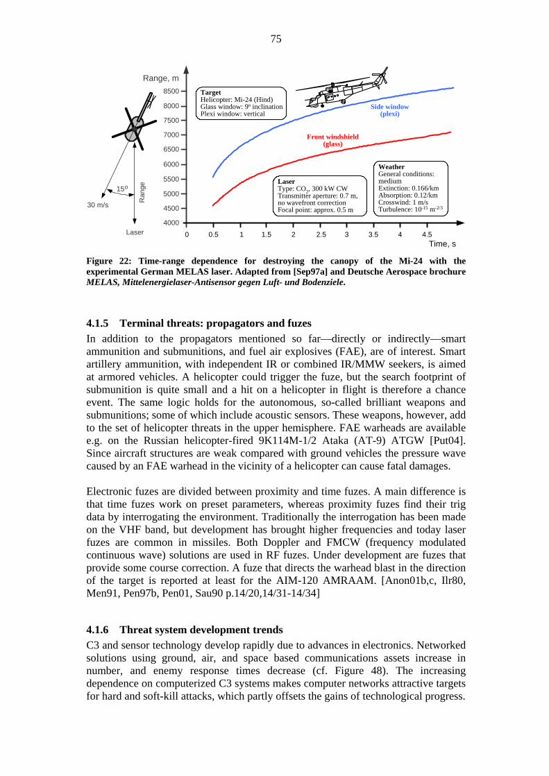
75
30 m/s 4500
0.5 1 41.5 2 2.5 3 3.5Time, s
Front windshield(glass)
Side window(plexi)
4000
5000
5500
6000
6500
7000
7500
8000
8500
4.50
Range, m
TargetHelicopter: Mi-24 (Hind)Glass window: 9o inclinationPlexi window: vertical
LaserType: CO2, 300 kW CWTransmitter aperture: 0.7 m,no wavefront correctionFocal point: approx. 0.5 m
WeatherGeneral conditions:mediumExtinction: 0.166/kmAbsorption: 0.12/kmCrosswind: 1 m/sTurbulence: 10-15 m-2/3
Ran
ge
Laser
15o
Figure 22: Time-range dependence for destroying the canopy of the Mi-24 with the experimental German MELAS laser. Adapted from [Sep97a] and Deutsche Aerospace brochure MELAS, Mittelenergielaser-Antisensor gegen Luft- und Bodenziele.
4.1.5 Terminal threats: propagators and fuzes In addition to the propagators mentioned so far—directly or indirectly—smart ammunition and submunitions, and fuel air explosives (FAE), are of interest. Smart artillery ammunition, with independent IR or combined IR/MMW seekers, is aimed at armored vehicles. A helicopter could trigger the fuze, but the search footprint of submunition is quite small and a hit on a helicopter in flight is therefore a chance event. The same logic holds for the autonomous, so-called brilliant weapons and submunitions; some of which include acoustic sensors. These weapons, however, add to the set of helicopter threats in the upper hemisphere. FAE warheads are available e.g. on the Russian helicopter-fired 9K114M-1/2 Ataka (AT-9) ATGW [Put04]. Since aircraft structures are weak compared with ground vehicles the pressure wave caused by an FAE warhead in the vicinity of a helicopter can cause fatal damages. Electronic fuzes are divided between proximity and time fuzes. A main difference is that time fuzes work on preset parameters, whereas proximity fuzes find their trig data by interrogating the environment. Traditionally the interrogation has been made on the VHF band, but development has brought higher frequencies and today laser fuzes are common in missiles. Both Doppler and FMCW (frequency modulated continuous wave) solutions are used in RF fuzes. Under development are fuzes that provide some course correction. A fuze that directs the warhead blast in the direction of the target is reported at least for the AIM-120 AMRAAM. [Anon01b,c, Ilr80, Men91, Pen97b, Pen01, Sau90 p.14/20,14/31-14/34]
4.1.6 Threat system development trends C3 and sensor technology develop rapidly due to advances in electronics. Networked solutions using ground, air, and space based communications assets increase in number, and enemy response times decrease (cf. Figure 48). The increasing dependence on computerized C3 systems makes computer networks attractive targets for hard and soft-kill attacks, which partly offsets the gains of technological progress.

76
Weapons technology relies ever more on electronics to improve precision and speed of execution. The need for electronic countermeasures to offset these improvements therefore rises. Simultaneously improvements in explosives and ammunition technology decrease the quantity of munitions needed for target destruction. DEW weapons gradually evolve, but kinetic energy will remain the premier agent for weapons effect. Traditional ballistic weapons will remain a threat also on the future battlefield due to their simplicity and insensitivity to countermeasures. Weapons and other combat assets will be increasingly mobile, and airborne platforms will play a greater role as carriers of weapons, reconnaissance, and C3 assets. The number of unmanned aerial vehicles (UAVs) will increase substantially. The development of unmanned ground vehicles is slow due to problems with artificial intelligence in guaranteeing safe and reliable operation of such vehicles.
4.1.7 Conclusions and implications for EWSP The chain of threat systems for a helicopter, together with EWSP and other means (support assets) for attacking the threats are shown in Figure 23.
Sensors for target detection andidentification.
Communication network for relayingdata to command centers.
Human-computer interaction commandcenters for processing target data.
Communication network for relayingtarget data to fire units.
Sensors for target tracking (includingfire control).
Weapon launchers and targetilluminators.
Weapon seeker or guidance commandreceiver/processor.
Weapon guidance & servo system.
Warhead fuze.
SEAD attack, flight routeselection.Attack
Seeker/receiver jamming,deception, disruption or
destruction.
Servo loop deception.
Fuze deception (prematuretriggering).
Attack
Attack
Attack
SEAD (COMJAM) attack.Attack
Hard kill and informationwarfare attack.Attack
SEAD (COMJAM) attack.Attack
Intelligence and missionplanning for threat avoidance.
Sensors for target detection andidentification. Counter
THREATS EWSP METHODS SUPPORT ASSETS
SEAD (hard-kill) attack.Attack
SEAD (soft/hard-kill) attack.Jamming and deception.Attack
Figure 23: Summary of Section 4.1, the chain of threat systems of battlefield helicopters and assets for countering the threats. A number of threat systems cannot be attacked by EWSP, but need hard- and soft-kill support assets. Due to the growing use of sophisticated weapons the importance of EW assets increases. An attack on weapon launchers and fuzes by EWSP means is an unlikely theoretical possibility. Legend: COMJAM=communications jamming.

77
The possibility of attacking the weapon launcher by EWSP means, as indicated by the dashed box in Figure 23, is primarily a future alternative for countering LBR missiles. Deception of proximity fuzes is practiced against artillery ammunition, but to aircraft EWSP the narrow endgame engagement geometry has so far precluded this technique. In conclusion it can be stated that the EWSP suite has potential to counter only a lesser part of threat systems—a fact that is obvious already from Figures 12 and 13—but the interaction of various countermeasures and their relative cost-benefit merits must be kept in mind.
4.2 Threat technology
4.2.1 Overview Section 4.1 and Figure 23 indicate threat technologies of primary importance to EWSP and therefore deserve a more detailed analysis. Figure 24 summarizes these technologies. In order to avoid repetition the following discussion is divided into technology groups, as marked by the templates in Figure 24. Guidance systems are discussed in connection with sensors.
RF SENSORS Mechanical
Monopulse
Active radar
Semiactiveradar
Semiactivelaser
Infrared
Legend:ESA=electronically scanned arrayPN=proportional navigation
Visual trackingSeekers and
guidance links
EWSP-related threattechnologies
Targettracking
Imaging
LaserEO trackers
ESA
Tracking radars
Passive
Guidancesystems
PN
Commandguidance
Other
Missilenavigation
Gun FCS
EO SENSORS
AcousticGUIDANCE
Figure 24: Summary of threat technologies of importance to EWSP of battlefield helicopters. Visual tracking will not be considered, since countermeasures to visual observation may violate the UN Protocol prohibiting Blinding Laser Weapons [Anon95a]; acoustic sensors have no effective EWSP countermeasures.
4.2.2 EO sensors
IR sensor and seeker technology The group of imaging technology consists of low-light television (LLTV) cameras, image intensifiers, and infrared cameras of various types. LLTV cameras are mostly used in naval applications and image intensifiers in short-range systems. IR technology is therefore of main interest to the present study. A review of IR detector
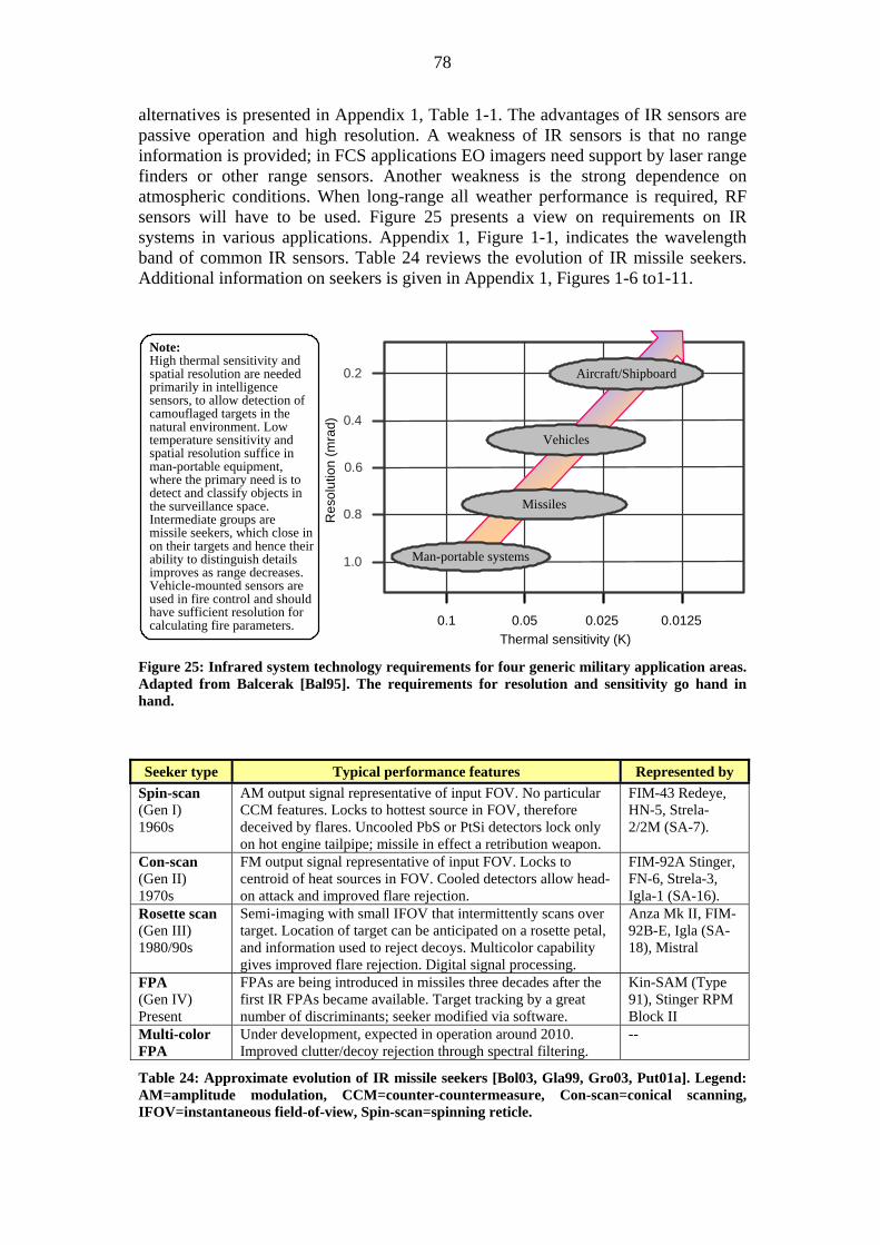
78
alternatives is presented in Appendix 1, Table 1-1. The advantages of IR sensors are passive operation and high resolution. A weakness of IR sensors is that no range information is provided; in FCS applications EO imagers need support by laser range finders or other range sensors. Another weakness is the strong dependence on atmospheric conditions. When long-range all weather performance is required, RF sensors will have to be used. Figure 25 presents a view on requirements on IR systems in various applications. Appendix 1, Figure 1-1, indicates the wavelength band of common IR sensors. Table 24 reviews the evolution of IR missile seekers. Additional information on seekers is given in Appendix 1, Figures 1-6 to1-11.
1.0
0.8
0.6
0.4
0.2
0.1 0.05 0.025 0.0125Thermal sensitivity (K)
Res
olut
ion
(mra
d)
Aircraft/Shipboard
Vehicles
Missiles
Man-portable systems
Note:High thermal sensitivity andspatial resolution are neededprimarily in intelligencesensors, to allow detection ofcamouflaged targets in thenatural environment. Lowtemperature sensitivity andspatial resolution suffice inman-portable equipment,where the primary need is todetect and classify objects inthe surveillance space.Intermediate groups aremissile seekers, which close inon their targets and hence theirability to distinguish detailsimproves as range decreases.Vehicle-mounted sensors areused in fire control and shouldhave sufficient resolution forcalculating fire parameters.
Figure 25: Infrared system technology requirements for four generic military application areas. Adapted from Balcerak [Bal95]. The requirements for resolution and sensitivity go hand in hand.
Seeker type Typical performance features Represented by
Spin-scan (Gen I) 1960s
AM output signal representative of input FOV. No particular CCM features. Locks to hottest source in FOV, therefore deceived by flares. Uncooled PbS or PtSi detectors lock only on hot engine tailpipe; missile in effect a retribution weapon.
FIM-43 Redeye, HN-5, Strela-2/2M (SA-7).
Con-scan (Gen II) 1970s
FM output signal representative of input FOV. Locks to centroid of heat sources in FOV. Cooled detectors allow head-on attack and improved flare rejection.
FIM-92A Stinger, FN-6, Strela-3, Igla-1 (SA-16).
Rosette scan (Gen III) 1980/90s
Semi-imaging with small IFOV that intermittently scans over target. Location of target can be anticipated on a rosette petal, and information used to reject decoys. Multicolor capability gives improved flare rejection. Digital signal processing.
Anza Mk II, FIM-92B-E, Igla (SA-18), Mistral
FPA (Gen IV) Present
FPAs are being introduced in missiles three decades after the first IR FPAs became available. Target tracking by a great number of discriminants; seeker modified via software.
Kin-SAM (Type 91), Stinger RPM Block II
Multi-color FPA
Under development, expected in operation around 2010. Improved clutter/decoy rejection through spectral filtering.
--
Table 24: Approximate evolution of IR missile seekers [Bol03, Gla99, Gro03, Put01a]. Legend: AM=amplitude modulation, CCM=counter-countermeasure, Con-scan=conical scanning, IFOV=instantaneous field-of-view, Spin-scan=spinning reticle.

79
Figure 26 shows the typical two-color missile seeker optical layout with Cassegrain mirror arrangement. The figure is of interest for the later discussion on countermeasures.
The dome:Aerodynamic heating of thedome is a major source of noisein IR seekers, particularly at sealevel. At Mach 3 the dometemperature rises above 500 oC.Improvements are theaerodynamic spike on the Iglas(SA-16 and SA-18) and theoctagonal cone of the Mistral.Long wavelength detectorstolerate more dome emittance.Popular dome materials are MgF2and Al2O3; other acceptablematerials are GaP, ZnS, andZnSe. Diamond domes are underdevelopment and expected to besuperior at long wavelengths.[Gla99, Gol02, Har96 p.45,80,Har99b, Hoy00, Kle97 p.349]
DomePrimary mirror &seeker gyro rotor
Preamplifiers
Spectral filter& detector 1(cooled)
Support lensBeam splitter
Spectral filter& detector 2
Secondarymirror
Gimbal/slip rings
Figure 26: Typical two-color seeker optical layout [Gla99] and requirements on IR missile domes. Motivations for longer wavelength detectors (3.2-4.8 µm or more) are to achieve lower dome emission and to escape solar radiation reflected from sunlit clouds [Har99b p.74, Hud69 p.238].83 According to Doo et al. [Doo02] the most favorable UV band in a combined UV/IR seeker is 0.37-0.43 µm; i.e., on the border between the visual and UV regions.
Table 25 summarizes typical flare countermeasure techniques, but the information cannot be related to particular missile types since unclassified sources disclose only the most basic ECCMs (electronic counter-countermeasures) of specific missile types. Even the seeker type may not be revealed. For instance, information on the Igla (SA-18 Grouse) claims it to have both an FM (con-scan) and rosette scanned seeker (cf. inconsistency in Tables 21 and 24).
Aim Method Kinematic and spatial recognition of flare separation rate and position. Effective for high separation rate between flare and aircraft. Spectral recognition, including dual band recognition.
Flare detection and identification
Flare ignition time (rise time) recognition. Detector shutting until flare has passed. Effective if only a single flare is ejected and the target is sufficiently distant. Seeker push-forward or push-up. Effective if the flare is not ejected in front of, alternatively above, the aircraft. Blanking of the lower-rear FOV quadrant. Effective if the flare drops below-behind the aircraft. Rejection of hot objects with multi-color discrimination. Effective if multi-color discrimination is possible and object separation is sufficient.
Flare rejection
Rejection of spatially irrelevant objects. Effective if seeker is capable of image processing.
Table 25: Missile seeker flare ECCM methods, grouped into flare detection/identification and flare rejection actions. [Dey94, Gla99, Phe98a, Phe98b, Sch99 p.449, Tay98, Vol95]. 83 Solutions for rosette scanned seekers can be found e.g. in Andersson [And03], Knight [Kni01], and Voigt and Gordon [Voi00].

80
Laser technology and guidance Lasers are part of helicopter threat systems in the form of laser range finders, semi-active target designators, guidance beams for LBR missiles, and laser fuzes. Table 26 gives an overview of typical LRF and designator lasers; these can be categorized as medium-energy, low PRF (pulse repetition frequency) lasers. LBR lasers are low-energy, high PRF (up to some 10 kHz) devices.
PLATFORM Portable Land vehicle Airborne Requirement Artillery
observation Tank/AFV
FCS Air defense
(AAA/Missile) Helico missile
guidance Fixed wing targeting
Maximum range 4-10 km 4-10 km 10-20 km 4-10 km 10-20 km Pulse energy 5-40 mJ 5-40 mJ 25-125 mJ 5-40 mJ 25-150 mJ Beam divergence 1-2 mrad 0.4-1 mrad 0.5-2.5 mrad 0.4-1 mrad 0.1-0.5
mrad Pulse rate Single Shot 0.1-8 Hz 6-20 Hz 4 Hz 5-20 Hz Duty factor > 10 s
interpulse Burst 10-100 pulses
100% 25-100% 100%
Range accuracy ! 10 m !5-10 m !2.5-5 m !5-10 m !1-10 m Atmospheric penetration
Compatible with DVO
Compatible with DVO, TV, FLIR
Clear to hazy weather
Clear to hazy weather
Clear to hazy weather
Table 26: Typical parameters of LRFs and designators [Byr93 p.83, Hew95]. Legend: DVO=direct viewing optics, FLIR=forward looking infrared, Helico=helicopter.
Figure 27 shows important wavelengths used by military systems. Of the numerous wavelengths possible for different lasers, only a few are used in practice. For instance, CO2 lasers usually operate at 10.6 µm but CO2 lasing has been demonstrated at least for the 8.9-12.4 µm band [Fre95 p.65]. Nd:YAG laser at 1.064 µm are the backbone of military lasers, but requirements on eye safety see increased use of Raman-shifted Nd:YAG or Erbium:glass lasers at 1.54 µm.
DEWs &laser CMs
Laser radar& illum.
Laserdazzlers
LRF &designator
LBRs
Application Wavelength [ m]0.2 1.0 2.0 3.0 4.0 5.0 9.0 11.0
O3H2OCO2
COCO2
H2OCO2 10.6
10.6
10.6
4.63.8
1.54
1.54
1.064
1.064
0.532
0.694,1.74...1.79
0.904
0.8….1.1….1.8
2x
2x
Legend:2x œ frequency doubling; stripedareas œ high attenuation.
1.315Lasers:Alexandrite: 0.36...0.82 mCO2: 10.6 m (8.9...12.4 m)Deuterium fluoride: 3.8 m (3.5...4.2 m)Er:glass: 1.50...1.604 mGaAs: 0.904 m (0.825...0.962 m)Iodine (Iodine:Oxygen): 1.315 mNd:YAG: 1.064 m (0.213...1.319 m)Raman-shifted Nd:YAG: 1.54 mRuby: 0.694 m (0.347...0.6943 m)
H2OH2OAbsorbingmolecule
Figure 27: Graphical presentation of the most frequently mentioned military laser wavelengths. The range 0.9-1.8 µm for beamriders covers semiconductor lasers in optical communication. [Fre95 p.65, Web99] Holmium YAG lasers at 2.06 µm have are also a possibility [Bro98 p.216].

81
The FOV of LBR missile receivers is directed to the rear, towards the laser beam source at the launcher. The receivers are therefore generally assumed immune to jamming. In addition, in order to keep the missile within the beam just after launch the beam has to be broadened, which lowers the beam power density at the target and delays detection by the target’s sensors.84
Return to azimuth frame
Switch to elevation frame
A
B
Note:The missile sees pulsetime intervals thatdepend on the missile’sposition in the scanraster (A or B).Synchronization to thescan pattern occursduring the time gapmarking return fromelevation to azimuthscan frame.
Azimuth frame Elevation frame
Figure 28: LBR guidance solution proposed in Higgins et al. [Hig84]. The figure gives an indication of the frame rate needed for accurate guidance, considering speed and maneuverability of missile and target. Other proposed LBR solutions are given in e.g. [Die87a, Die87b, Jam00, Mil74, Pit94, Sog80, Ton84, Ton95].85
4.2.3 RF sensors Passive ESM and SIGINT assets are an indirect threat to helicopters and have to be dealt with by LPI techniques, emission control and other procedural means. Radio receiver technology will not be covered in more detail, but a review of EW receivers is provided in Appendix 1, Table 1-2(a-d). It can be noted, however, that South-Africa shot down six helicopters in the Angola War by interceptions based purely on ESM information [Rad02]. It has been claimed that “(…) every ECM system should be designed to counter the threat to the specific craft to be protected, not every radar in the general area” [Wie91 p.122]. According to this, a central question to helicopter EWSP is which radars or radar types are important enough to be of concern. The success of the 2K12 Kub/Kvadrant (SA-6 Gainful) and the ZSU-23-4 in the 1973 Yom Kippur War led Western militaries for a long time to focus on the emitters of those systems.86 Earlier
84 According to Pengelley the guidance beam energy level of the UK-built Starstreak LBR system is some 60 dB lower than that of an Nd:YAG laser range finder [Pen99b]. Since the peak power density of a Nd:YAG laser range finder is approximately 106…108 W/m2 at normal detection ranges (atmospheric attenuation not considered), detection of Starstreak’s guidance beam should require sensitivities better than 10-6 W/cm2 if Pengelley’s claims are correct. 85 It is of interest to note that the Starstreak is reported to be guided by two laser beams, one of which is scanned horizontally and the other vertically to create a grid [Cul99 p.29, Pen99b]. 86 The mobile Straight Flush search radar of the SA-6 reportedly operates in the C-band (5-6 GHz), and its CW (continuous wave) tracking radar and illuminator in the low X-band (8-9 GHz) [Lyn04 p.270, Put04]. The Gun Dish radar associated with the ZSU-23-4 reportedly operates in the Ku-band (14.6-15.6 GHz) [Lyn04 p.269]

82
the attention had been on the S-75 Dvina (SA-2 Guideline)—and its 700-800 MHz guidance uplink [Zal89 p.76] still influences EW specifications. 87 The previous discussion is contradicted by views on generic threats (cf. Section 1.4.3), according to which a modern EWSP suite cannot intrinsically be tied to one specific scenario. Also, the discussion in Section 3.3.3 on mission survivability opens a broad spectrum of threats that need be considered. Table 27 gives a general review of radar parameters of importance to helicopter EWSP. Parameter Importance Parameter range
Carrier frequency
Single most important parameter for radar identification.
The 2-18 GHz band most important to EWSP. Tracking radars increasingly use Ka-band, and weapon seekers the W-band. Frequencies <2 GHz increasingly cluttered by civil emitters. X-band contains e.g. the bulk of civil navigation radars.
PRI (PRF) PRI ranks second most important parameter for radar identification.
PRF from <1 kHz (search radars) to 1 MHz (PD missile seekers). Fixed, staggered, or completely random (in MTI radars).
Pulse width Third most important parameter for radar identification. Related to BW and PRI.
Pulse lengths from <0.1 µs to >10 µs. Duty cycles from 0.1%, and up to 50% for ICW operation.88 Risk for PW corruption by multipath propagation.
Scan type Mechanical scan: Indicates threat’s intension and is a target for deception. ESA antennas complicate the situation.
Circular or sector scan (0.2…2 Hz) for search radars. Intermittent for tracking radars in acquisition phase, and virtually constant when locked. Random looks by ESA radars.
Power Determines power density at the receiver, which is a main issue to detection.
Transmit powers from <1 W (FMCW) to the MW class (high-power pulsed search radars). EWSP receivers can see any power density depending on the range to the radar.
Bandwidth (BW)
Puts similar requirements on the EWSP receiver.
Pulses shorter than 0.1 µs require > 10 MHz IBW. Frequency agility up to 10% of carrier frequency. (BW i 1/ )
DBF Digital beamforming (DBF) allows beam nulls to be placed in the direction of a jammer.
True DBF by ESA antenna, pseudo-DBF (SLB/ SLC) by added auxiliary antenna(s). Jamming suppression -20…-30 dB, with potential for more.
Polarization Influences antenna losses and is needed as a jamming parameter.
Any polarization must be expected. Antenna cross polarization (-25…<-40 dB of main polarization direction) is an avenue for jamming.
Coherence Introduces requirements on jamming coherence.
Depends on victim radar’s CPI and stability of its local oscillator.
Coverage Determines whether a target will be detected or not.
Detection requires that spatial and temporal search conditions are satisfied; frequency domain influences lobe properties and hence the space.
Table 27: Radar parameter considerations of importance to helicopter EWSP and survivability [Bog90 p.75, 84; Far90 p.9/8; Mor96 p.17; Ner91 p.178; Sch90, Sch99; Sko80,87].89 Legend: CPI=coherent processing interval, IBW=instantaneous BW, ICW=intermittent CW, LFM=linear frequency modulation, MTI=moving target indication, PD=pulse Doppler, SLB=sidelobe blanking, SLC=sidelobe cancellation, =pulse/code element length.
87 The family of S75 systems includes the Soviet/Russian type designations Dvina, Desna and Volkhov, but the US/NATO designation for all is SA-2 Guideline [Fis02a]. 88 Pulse compression ratios vary from <13 to 100-300 and more [Sko80 p.422]. Binary pseudorandom sequences are preferred, because they have desirable autocorrelation properties and are relatively easy to generate. However, polyphase codes make the radar susceptible to Doppler-induced phase shifts. [Vac93 p.28, 38] 89 Fighter aircraft radars have a multitude of modes for different applications. The AN/APG-73 radar on the F/A-18, for instance, is reported to have 14 operational modes [Bro98 p.297].

83
Ground-based long-range search radars are generally not a threat to helicopters, and have not been considered in Table 27. Major radar ECCM techniques are methods for increasing parameter selectivity. Appendix 1, Table 1-3, reviews important radar selectivity methods and also points out LPI factors.90
4.2.4 Threat timelines Threat timelines include reaction times, deployment times and development times. Reaction times are the time delays between target detection and effector impact on the target. Reaction delays are counted in seconds and are due to technical as well as human and organizational reasons (cf. [Bal98 p.113]). Deployment delays are primarily due to delays in logistics and take anything from minutes to months. Development time is the time between the decision to develop a threat (or threat system) until its operational readiness, and may run from months to years, even decades. The timelines are exemplified by Figure 29, where the MANPAD case exemplifies reaction times.91 Development timelines in Figure 29 underline a basic problem of sensors: Sensor systems live for a decade or two, while the gestation period for countermeasures can be very short particularly in time of war. [Rad78] Software configurability is increasingly important for threat systems and CMs alike.
Deployment of new threatmodes
Weaponactivation
Reactiontime
Visual detection
0 3 4.2 7.2 10.6 14-17
Elapsedtime (s)
Missile impactExample:MANPAD reaction timeline
Deploy-ment time
Deployment of troops &equipment to conflict area
Combatredeployment
Events &duration
Develop-ment time
Weapon systemreconfiguration
Combat system modificationor upgrade program
Developmentof new system
Events &duration
Minutes Weeks/MonthsDaysHours
Decade(s)Months/YearsWeeks
Identifi-cation Gyro spin-up IR acquire,
aim, fire Time of flight
Figure 29: Typical threat timelines. The MANPAD reaction time budget (bottom) is adapted from [Anon00a, Hew98, Kre97] and should be seen as an idealized case with the gunner having accurate advance informtaion on the incoming threat.
90 It is worth noting that spread-spectrum techniques are not equivalent to LPI techniques. LPI designers must consider ELINT capability. For instance, chirp modulation may be classified as a spread-spectrum technique but an ELINT processor only need an approximation to the phase slope to recapture the chirp processing gain. [Car88] 91 Another example of system reaction time is reported for the Russian ZSU-23-4 without its radar operational: The shortest time recorded is 32 seconds to open fire after the appearance of a helicopter, with the average time being around two minutes [Cob84, Mul80].

84
4.2.5 Threat technology development trends Recent years have seen rapid progress in IR technology, and cooled staring array detectors with a minimum resolvable temperature difference (MRTD) of 10 mK will abound. QWIP technology (quantum well infrared photodetectors) is a likely candidate for multispectral FPAs. However, the time lag between an FPA matrix being commercially available and its incorporation into missile seekers has been over a decade. Based on this 2048x2048 FPA matrixes can be expected in missiles within a decade, and 4096x4096 matrixes around the year 2020. [Gla99] Suggested solutions for home-on-jam (HOJ) capability in IR guided missiles promises a countermeasure to DIRCMs (directed infrared countermeasures) [Lan98, Put01a]. Dome structures will improve and dome-induced noise be reduced—in part due to use of longer wavelength seekers. Alternatives to the bulky and costly electromechanical gimbals are actively sought [Hår99]; one candidate is FOV-multiplexer technology [Tho98]. FPA seekers are software reconfigurable and will therefore shorten the race time between threats and countermeasures. LBR missiles do not challenge the quantity of fire-and-forget IR missiles in the future, but their immunity to countermeasures and relative stealth will remain a problem to EWSP. Fiber-optic guidance will eventually replace wire-guided ATGWs and they will—as the first systems today do—also have fire-and-forget capability. Although fiber-optic ATGWs are comparatively slow their elevated flight path and top-attack capability make them a threat to helicopters; target speed, however, decreases missile hit probability [Kra92]. High-energy lasers will eventually be a threat to slow ATGWs. One research goal is to achieve 100 kW laser output by 2007 with an 0.808 µm Nd:GGG system that can operate from a terrain vehicle, which allows small-size threats to be defeated in a few seconds [Jon03, Sco04]. Radar technology is a mature field but its progress shows no end, primarily due to progress in digital signal processing. The long-awaited breakthrough of ESA radars has been delayed by the slow emergence of low-cost MMIC (monolithic microwave integrated circuit) transmit/receive modules. The ESA radar is, however, less attractive for long-range air-surveillance applications [Sko02]. Optical beamforming promises true time delay beam steering, which is required for wideband operation with large scan angles [Cha03]. The reliability of traveling-wave tubes (TWTs) has improved, thereby retaining the attractiveness of TWTs when wide bandwidth is required. Emerging competitors are the so-called clustered-cavity klystrons and high-power gyrotrons [Gra99, Sko01,02]. Further improvements to clutter rejection and other long-standing radar problems need be found in signal processing theory and software algorithms. HF-UHF radars have seen renewed interest due to their anti-stealth properties, with digital signal processing improving their inherently poor resolution [Gru04; Kus97,98; Yat97]. The interest of the telecommunication industry in pseudonoise (PN) spread-spectrum technology will give a push to PN radar technology. PN transmissions are innately difficult to detect, and also provide means to disguise radar emissions as civilian signals. Another potential method is passive radar technology; that is, to detect reflected target signals originating from civil transmitters. If no suitable transmitter is available the radar can shift to an active PN mode. [Kus95] Finally, networks of combined radar, SIGINT, EO and other sensors will increase as a result of the present interest in network centric warfare.

85
4.2.6 Opportunities for electronic countermeasures The performance of electronic systems can be influenced by electronic countermeasures (ECMs) in four main ways: by decreasing the sensor’s signal-to-noise ratio (SNR), by deceiving the sensor, by disrupting or destroying the sensor or a part of it, and by influencing the feedback loops of the receiver. Table 28 summarizes the chances for these countermeasures against each threat technology or factor discussed above. It can be noted that IR tracking sensors are particularly susceptible to countermeasures during the acquisition phase, before a solid track is being established and thresholds are set [Tay00]. Technology ECM type ECM goal
Noise or SNR reduction
Introduce IR radiating or absorbing medium between target and sensor, or introduce noise into the sensor’s detector.
Deception Introduce decoys in the sensor’s FOV, or introduce deceptive signals into the detector.
IR sensors
Disrupt/destroy Induce disruptive or destructive high-power signal to lenses, detector elements or sensor electronics.
Noise or SNR reduction
Introduce IR radiating or absorbing medium in the seeker’s FOV, or introduce noise into the seeker’s detector.
Deception Introduce decoys in the seeker’s FOV, or introduce deceptive signals into the detector.
IR seekers
Disrupt/destroy Induce disruptive or destructive high-power signal into window, detector elements or seeker electronics.
Noise or SNR reduction
Introduce radiating or reflecting medium in the laser path, or introduce noise into the laser receiver.
Deception Introduce decoys in the laser path, or introduce deceptive signals into the detector.
Laser technology
Disrupt/destroy Induce disruptive or destructive high-power signal into detector elements of laser receiver or seeker electronics.
Noise or SNR reduction
Introduce radar reflecting or absorbing medium between target and radar receiver, introduce noise into the receiver.
Deception Introduce decoys in the radar’s search volume, introduce deceptive signals into the receiver, introduce false targets that overload signal processing capacity.
Radars
Disrupt/destroy Induce disruptive or destructive high-power signal into the radar receiver’s front end or into receiver electronics.
Noise or SNR reduction
Degrade SNR of sensors that form a part of the servo feedback loop.
Deception Introduce beat signals into the servo feedback loop through sensor signals, or signal that offsets the AGC.
Servos & FCS
Disrupt/destroy Induce disruptive or destructive high-power signal into the sensors or into sensor electronics.
Threat timelines
-- Reaction timelines: CM directed at sensors as mentioned above, tactical measures to delay detection and identification.
Table 28: Conceptual solutions for threat technology countermeasures. The basic principle is repeated in all sensor cases, but the feasibility of the methods varies from technology to technology. Threat development and deployment times cannot be influenced by EWSP, but need a set of actions ranging from armed attacks and tactical deception to political influence. Legend: AGC=automatic gain control.

86
4.2.7 Conclusions and implications for EWSP The helicopter cannot outmaneuver an approaching threat, but threat reaction times are often too long for engagement if the helicopter keeps moving and makes good use of terrain masking. This places NOE capability and aircrew situational awareness (SA) among the most important susceptibility reduction means for battlefield helicopters. Hard- and soft-kill support assets that can suppress enemy threat systems come next in importance for survivability, and EWSP rates third. Threat technology is the key to effective CMs, but countermeasures have to be tailored to the threat. Applying CMs against threats that are not susceptible to such actions is a waste of resources and potentially harmful, although they may have some positive influence on aircrew moral.
4.3 EWSP countermeasure technology
4.3.1 The scope of EWSP countermeasure technology Countering a threat by EWSP requires, first, threat detection and identification, and next execution of effective countermeasures. This is a repetition of the sequence for flare rejection, discussed in Table 25. The chain of events and alternative actions is somewhat more complex, as demonstrated by Figure 30.
Threat systems Signatures Detection &identification
Execution ofcounter-
measures
Warning
Contributing factors:- spatial distribution- temporal distribuiton- frequency distribuiton- modulation- power- propagation path- clutter
Contributing factors:- spatial coverage- temporal coverage- frequency coverage- sensitivity- processing capacity- identification process
Aircrewactions
Com
man
ds
Data Counter-measures
Maneuvers
Contributing factors:- workload- delays- crew assessment reliability
EWSP suite
Feedback
Influ
ence
Figure 30: Events and actions in the EWSP countermeasure process, and major factors involved in the process. The influence of CMs and maneuvers on threats is shown as a feedback loop.
The following discussion will proceed according to the events in Figure 30. That is, first a discussion on warning systems that perform the detection and identification task, and then a discussion on countermeasure technology. Questions related to the control of the countermeasure process will be covered in Chapter 5, together with other systems aspects.

87
4.3.2 Warning system technology
General requirements on warning systems Concluding from the earlier discussion the warning system of an EWSP suite of battlefield helicopters shall fulfill the following criteria: The warning system shall provide sufficient, timely, accurate and prioritized information on relevant threats to support decisions on further actions. On this level of generalization the criteria are applicable to any platform. For the present work the criteria will act as a guideline, but it should be recognized that they are idealized and cannot be satisfied in a strict sense. Judgement and analysis are required to find practical solutions. Figure 31 shows the typical spatial coverage of helicopter warning systems and RF jammer.
RWR
RFJLWR
90°
60°
MWS MWS
RWR
RFJLWR
Elevation coverage:RWR ±45°RFJ ±30°
LWR ±30°MWS ±50°
RFJ
RFJ
RWRMWSLWR
RWRMWSLWR
45°315°
135°225° 100°
60°
90°
100°
Azimuth coverage:RWR 360°
RFJ ±60° fore/aftLWR 360°MWS 360°
Figure 31: Spatial coverage of the proposed ASPIS EWSP suite on the Apache attack helicopter [Oeh98]. Top-attack weapons will not be detected. In practice the coverage has blind sectors due to rotors, tail boom, external stores and other protruding structures [Boe95]. Pod-mounted sensors on Dutch Apache helicopters allow spherical MWS coverage [Jan04b]. Information on blind sectors is classified, since they represent weak spots. Legend: LWR=laser warning receiver, MWS=missile warning system, RFJ=RF jammer, RWR=radar warning receiver.
Radar warning receivers The RF environment of RWRs is dense with signals from friendly, enemy, and neutral transmitters; in a relative sense the RWR has to operate in a more demanding environment than the other warning systems. The detector part of the RWR is one of the RF receivers listed in Appendix 1, Table 1-2. CVRs (crystal video receiver), IFMs (instantaneous frequency measurement), and tuned receivers are used in rotorcraft EWSP applications, while digital receivers are emerging. In cases when only the most basic RF warning system is needed the CVR receiver is still a viable option, assuming that the RF environment does not hold strong simultaneous signals. In more demanding cases each receiver type has to be judged against the specific requirements of the environment. Table 29 summarizes the most important questions on RWR performance. Threat identification and classification are today computerized processes [Bro98 pp.205-207], although a trained person still can identify many threats by listening to the PRF and AM signal of a radar. Figure 32 shows in a block diagram the manipulation, identification and classification process of intercepted signals.

88
RWR issue Contemplation Threat scenario
Ideally the RWR should be tailored to mission threats and not be burdened with undue capabilities. A generic scenario asks for sufficient HW capability, modularity and tailoring by SW. A decision is also required if the RWR is to serve only the self-protection task, or if it also should support tactical intelligence.92
Probability of intercept (POI)
POI is a loosely defined term [Tsu86 p.76]. POI should be as close to 100% as possible, which is the strength of wide-open receivers. The POI of tuned (and digital) receivers depends on the IBW, scan rate and signal environment. The risk of missing high-threat emitters is alleviated by an MDF-driven search strategy.
Sensitivity The threat footprint of low-flying helicopters is small and a low-sensitivity receiver (CVR) has traditionally been sufficient for self-protection [Sch86 p.34]. LPI technology introduces new challenges, as does requirements on improved SA. Digital receivers promise, among other benefits, high sensitivity.
Signal density
Density is scenario dependent. In addition to threats, friendly and neutral emitters (including cellular phones) must be accounted for. RWR receiver & processor load increases with increased sensitivity, bringing risk for degraded performance.
Probability of false alarm (Pfa)
Pfa > 1/hour easily leads to loss of confidence in the RWR. High receiver sensitivity and low resolution, together with threat identification ambiguities, are main contributors to high Pfa. Adjustable sensitivity, filtering of irrelevant emitters, and mission-tailored MDFs are methods to decrease Pfa.
Frequency band
The 2-18 GHz band is almost institutionalized for RWRs, but it should be asked if S-band and below is needed for helicopters. The Ka-band is of increasing importance, and some threats exist in the W-band.93
Frequency resolution
The maxim “the more the better” is valid, since frequency resolution contributes to resolving similar emitters and thereby avoiding ambiguities and false alarms.
Signal modulation
Radar selectivity (Appendix 1, Table 1-3) asks for capability to operate with pulse, PD, and CW/ICW emitters; with PRF staggering/jitter, frequency agility/jitter and interleaved modes; and to resolve major antenna scan patterns.
Angle of arrival (AOA)
High AOA resolution enhances deinterleaving, high accuracy supports RF jammer cueing. Geolocation capability may be required in SEAD operations [Nor99a] and also as an option for attack helicopters, but goes beyond traditional self-protection.94
Antennas Influence spatial coverage, AOA accuracy, system sensitivity, and frequency dependence of the total installation. Cavity-backed spiral antennas are popular due to wide BW, circular polarization, and near-Gaussian gain pattern [Vac93 p.231].
MDF A large, general-purpose MDF leads to risk of ambiguous identification of similar emitters. Tailoring the MDF for the mission at hand filters out irrelevant emitters but requires accurate tactical intelligence and EW support personnel at the base.
Conclusion A hybrid of different receiver types mitigates weaknesses of any single type. CVR+IFF and CVR+YIG are common solutions. Digital receivers may also require support by other receivers to avoid a narrow-IBW system with low POI.
Table 29: Contemplations on RWR issues in the helicopter environment. 95 Legend: HW=hardware, MDF=mission data file, SW=software.
92 Operational experience shows that tactical aircraft entering high threat environments is often the first to detect emitters in such areas, even though more sophisticated ELINT platforms have monitored the same area at stand-off range [Rad99]. In Bosnia the high-flying U-2 was relegated strictly to stand-off range due to proliferation of long-range, high-altitude surface-to-air missiles [Hay95]. 93 The AN/ALQ-211 SIRFC, under development for different US platforms, is obviously the first rotor-wing EWSP suite to include a W-band in the RWR [Anon97d]. 94 The usual arrangement with four quadrant antennas (cf. Fig. 31) on the platform gives an AOA accuracy around 10o RMS (root mean square) for a good installation [Bro98 p.195]. 95 The British Sky Guardian 2000 (core of the HIDAS system) is a present-generation RWR for helicopters. It is advertised to have the following performance [Put04, Whi98]: (1) UHF to Ka band coverage (0.5-18 GHz and 32-40 GHz) for pulsed and CW emitters. (2) Hybrid CVR receiver. (3) Pulse sensitivity in excess of –50 dBmi. (4) CW sensitivity in excess of –60 dBmi. (5) Dynamic range in excess of 50 dB. (6) Full capability in an environment exceeding 1 Mpps. (7) POI 100%. (8) Time to intercept <1 second. (9) Threat library with up to 4000 entries. (10) Weight 22 kg including RF heads and amplifiers. Legend: HIDAS=commercial acronym.

89
RF part Featureextractor
CNIsystem
PDW1
PDW2
PDW3
PDWN
.
.
.
Pulsebuffer
PDW: frequency,TOA, AOA, PW,
amplitude, etc.
Nav
igat
ion
data
Histogrambased e.g. on f,
PW, AOAHistogram +
PRI, amplitudeetc. data
DATAMANIPULATION
Emitter2
Emitter3
EmitterN
.
.
.
MDF
Classifier
Emitter1
THREATIDENTIFICATION &CLASSIFICATION
Informationon threat
type, locationand lethality
Legend:CNI=communication, navigation, andidentification; f=frequency; PDW=pulsedescriptor word; PW=pulse width.
Patternextractor& tracker
Deinter-leaver
Signalintercept &digitization
Figure 32: The emitter identification and classification process. Adapted from Vaccaro [Vac93 pp.207-211]. Alternative approaches are presented in e.g. [Coo89, Gra86 pp.222-224, Lyn04 pp.135-145, Ner01 pp.341-344, Tra94]; deinterleaving algorithms are discussed e.g. in [Wil93b].
Missile warning systems Three technological alternatives compete for the missile warning market: CW or pulse Doppler (PD) radars, IR detectors, and ultraviolet (UV) detectors. Their respective merits are given in Table 30. The detection range of IR systems is superior to UV under all atmospheric conditions except for drizzle. Detection range, however, is not important per se; the central issue is the warning time before missile impact. The advantages of UV detectors coupled with the less severe impact of their weakness in the helicopter environment have made them the favored alternative in helicopter EWSP. [Car99, Cos99, Gel01, Ner01 p.362, San96, Sim99] Type Properties
PD operates e.g. in L-band to avoid ESM/RWR systems operating only above 2 GHz. Strengths Long-range, all-weather capability, controllable false-alarm rate,
independent of missile emissions, missile time-to-go information.
PD
Weaknesses Active transmitter, strong ground clutter at low altitudes, rotor blade interference on helicopters, antenna space requirement, decreasing RCS of tactical missiles.
IR detection typically in 3-5 m band; either mechanical scanning or FPAs. Strengths Detects both plume emission and hot engine parts, including PBO detection;
lower atmospheric attenuation; high angular separation of targets.
IR
Weaknesses Strongly clutter limited performance, risk for saturation at short ranges due to need for high sensitivity to provide long-range detection, complexity due to need for cooling.
UV detection of missile plume in the solar-blind region at 0.2-0.3 m; built around an image-intensifier. Strengths Minimal background clutter, hence lower demand on signal processing and
reduced complexity; no cooling required; mature technology; lower cost.
UV
Weaknesses No PBO detection, restricted detection range due to ozone attenuation, UV clutter from man-made sources, requirement for sharp cut-off filter at approx. 0.29 m, possibility that UV threat decoys will be developed.
Table 30: Strengths and weaknesses of MWS technologies [Bha97, Cos99, Fos01b, Her00, Kol65 p.118, Law93, Moa78, Rea96, Sch99 p.453, Sim99, Tay98, Wil93a p.80]. Properties of IR and UV are in relation to each other; only monochromatic IR is considered. Legend: PBO=post-burnout.

90
Laser warning receivers The chances for a helicopter to evade a laser-based threat once it has been fired at the helicopter are mostly low. Even when the helicopter’s LRF provides advance warning, a shell from the main gun of an MBT is only seconds away. The value of the LWR in the traditional self-protection sense—as represented by Figure 30—is therefore limited. The situation improves if the LRF measurement is made by a field artillery fire control squad, in which case the fire is a minute or two away. A further motivation for the LWR can be found if the EWSP suite is able to correlate data from multiple sources in order to decrease ambiguity of threat identification. Table 31 presents central LWR technology questions. LWR challenge Solution Note
Pulse rise time. Not entirely reliable due to rapid sun glitches, especially from helicopter’s tail rotor.
Pulse energy. Challenging, since the dynamic range of LBR beams and indirect LRF splashes (low energy), and direct LRF hits (high energy), is 50 dB (optical) or more.
Polarization. Complex measurement techniques, false alarms from partially polarized non-laser sources.
Signal coherence. Military lasers are only partially coherent since the focus is on beam width, bandwidth and power density.
Suppression of false alarms
Sensitivity. Very high sensitivity would allow determination of TOA between direct port scatter and indirect main beam.
LBR signals Sensitivity. Tradeoffs required to achieve 10-5 W/cm2 or better; related to false alarm rate, bandwidth, dynamic range, etc.96
AOA resolution
Detector array. Old single detector LWRs achieve only ±45° resolution, new systems reach ±1°. True need is a controversial issue.
Wavelength band
-- Typically 0.5 m to 1.6 m, addition of MWIR and LWIR bands increases costs and complexity.
Wavelength resolution
Multiple detectors. Two partly overlapping detector wavelengths resolve total band in three parts (Si & Ge diodes for 0.5-1.6 m band).97
Table 31: Major challenges in LWR technology and alternative solutions [Col98; Dun89; Man96; Wil93a p.27,55,116,118,141]. Note that the column “solution” includes both beam parameters and LWR solutions. Legend: AOA=angle of arrival, Ge=germanium, LWIR=long-wave IR, MWIR=medium-wave IR, Si=silicon, TOA=time of arrival.
4.3.3 Countermeasure technology
General requirements on countermeasures Concluding from earlier discussions the execution of countermeasures by an EWSP suite of battlefield helicopters shall fulfill the following general criteria: Electronic countermeasures shall be implemented optimally in time, space and frequency, and with maximum effect on the threat system. Countermeasures shall not endanger the
96 It is common to protect LWRs with wavelength-adapted filters to reduce sensitive at wavelengths where high irradiance can be encountered, e.g. 0.532 m, 0.694 m, 1.064 m, and 1.54 m; and to strive for peak sensitivity around 0.9 m. 97 Laser detectors typically are semiconductor avalanche diodes. Imaging LWRs, e.g. based on CCD (charge-coupled device) technology, have been shown to give subdegree angular resolution, but have low dynamic range and produce no wavelength information [Col86].

91
helicopter or its crew, nor friendly forces, non-combatants or civilian property. As with the previously defined criteria for warning systems these criteria are generic and applicable to any platform. The last criterion “(…) shall not endanger (…) civilian property” should be seen as a ROE requirement for PSO conditions. Figure 33 presents an overview of the main problem set that needs to be solved in the EWSP countermeasures process.
PARAMETERS TO BRINGINTO THE TIME-SPACE
DOMAIN:
Note:dx/dt refers to time-dependentchanges, such as rise/fall times.
Time
Space
Frequency
Phase
WavelengthIdentification
dx/dt
Modulation
Power
Energy
Frie
ndFo
e
ReactivePreemptive
Execute or not, and ifyes, in which
direction and for howlong?
Emit or not, and ifyes, in which
direction and for howlong?
Reaction time?Single or multiple
shots?Lead angle?
Obstructions?Lock-on?
Tracked or not?Time to impact?
Single or multiplethreat?
Terrain masking?Miss distance?
TIME-SPACE DOMAIN
Maneuvers
Range
Coverage
Lobe/dispersionAttenuation
Timing
ROE
Figure 33: Time-space domain (friend/foe space) of EWSP countermeasures and parameters to bring into the domain in order to find a method for effective countermeasure execution. The set of questions are similar for friend and foe, but differ for preemptive and reactive actions. Questions to be brought into the time-space domain are scenario dependent, but valid for friend and foe alike.
RF countermeasures Passive RF countermeasures in the helicopter EWSP environment equal to chaff, even when called aerosols for use against millimeter-wave seekers [Per99]. General requirements on chaff are given in Figure 34; an extended view on chaff ejection is presented in Appendix 1, Figure 1-12. A vital question is how to dispense chaff; bearing in mind the air flow of the main and tail rotor and the slow—even zero—speed of the helicopter. If a chaff burst is sucked into the rotor vortex of a helicopter hovering at low altitude, the chaff will highlight the helicopter to the radar. One attempt to solve the problem is by dispensing chaff to the rear, into the air flow of the tail rotor. The advantages of this method are fast blooming and Doppler broadening due to the violent movement of chaff filaments in the air flow. The disadvantage is that chaff bursts always are located to one side of the helicopter, which may not match requirements of engagement geometry. The history of active RF electronic countermeasures (ECMs) is as long as that of EW, stressed by the fact that the number of radar ECM techniques listed in Van Brunt [Bru78,82,95] is close to 300, and more methods are proposed in patents and other publications. The basic techniques, however, are few; other techniques are resorted to when conditions so demand. Table 32 lists the primary RF threats to helicopters and contemplates countermeasure issues. Figure 35 presents RF tracking

92
guidance methods and classic ECM techniques to defeat these methods. Table 33 reviews the main jamming techniques mentioned in Figure 35.
Requirementson chaff
Adequate dipole lengthto tune to threat radar
wavelengthAdequately rapidblooming time tocreate shielding
cloud.
Adequate ejectionsequence to create
optimal effectAdequate dynamicsto impede Doppler
processing by threatradar
Adequately lightweight to maximize
cloud persistence Adequatecoordination with
RF jammer
1
Adequately low”birdnesting” properties
to maximize cloudreflectivity
2
4
5
8
7
Adequate dipolenumber in cartridge tomask aircraft’s RCS3
Adequateconsideration of
engagement geometry
9
Adequateconsideration of
platform speed onuseful cloud life
Adequateconsideration of
helicopter rotor airflows on chaff
11
6
10
Figure 34: Requirements on chaff. Some requirements are dictated more by general EW than by EWSP; but e.g. fall rate (requirement 4) is important to EWSP if a chaff-dispensing rocket is fired ahead of the helicopter. References for respective requirement: 1 [Ner01 p.460, Sho85]; 2 [Sch99 p.427, Sho85]; 3 [Ner01 p.461, Sho85]; 4 [Sch99 p.421]; 5 [Anon92b, Phe98a]; 6 [Dun96]; 7 [Bru78 pp.498-503]; 8 [Phe98a]; 9 [Bru78 pp.514-519, Phe98a]; 10 [Phe98a]; 11 [---].
ACTIVE RF COUNTERMEASURES: PHILOSOPHY RF threat Contemplation
Search radars The helicopter is a weight and power constrained platform that does not allow high-power RF jammers. Achieving sufficient burn-through range even against short range search radars is difficult, but may be a necessary precondition for sufficient effect on gun FCS and semi-active guidance [Ner01 p.239]. A dedicated escort jammer platform may be needed for jamming search radars.
Tracking radars Guidance types of importance are semi-active CW (some SAM systems), and active pulse and PD radars (FCS radars and missiles) including command guidance. Tracking methods in order of increasing performance and cost are, conical scan, lobe switching, COSRO, LORO, conopulse, and monopulse [Lot90 p.129, Ner01 p.137]; with HOJ as fallback. Monopulse is used in modern systems, but other types must be expected. Frequency agility is used in all modern systems.
Guidance links Jamming has to be injected through the backlobes of the missile’s rear-looking receiver antenna. Required jammer power exceeds helicopter capability. The tracking radar is more vulnerable.
Conclusion The motivation for RF jammers on helicopters is questionable, unless the aircraft is used for deep-penetration CSAR or special operations. Even in that case an escort jammer may be a more viable solution.
Table 32: Contemplations on jamming RF threats with a helicopter EWSP suite. Helicopter weight and power constraints put major restrictions on opportunities. Legend: COSRO=conical scan on receive only, LORO=lobe-switching on receive only, SAM=surface-to-air missile.
Expendable repeater jammers can offer some potential for helicopters since towed decoys may not be practical for helicopters, although a towed helicopter decoy is proposed in [Col80]. Expendable repeaters/transponders ejected from standard C/FDs (chaff/flare dispensers) would be a lower-cost solution than on-board jammers or, alternatively, as a complement to the on-board jammer. However, no such decoy for helicopters is known to be in operational use.

93
Cross-eye/pol
Semi-active
Active
Inverse gain
Noise jamming
JAMMING TECHNIQUES
Range: RGPO
Velocity: VGPO
Modulation-specific requirements
PD
Pulse
CW
Terrain-bounce
LORO
COSRO
monopulse
conical scan
Angle-specificrequirements
Chaff illumination
Angle:
lobe switching
Signal return time
Note:CMs against RF command links are notfeasible for helicopters, the efforts shouldinstead be aimed at the tracking radar.
Range/speed-specific
requirements
Acquisition Chaff
Commandguidance
RF tracking& guidance
conopulse
Figure 35: RF tracking guidance taxonomy and main jamming techniques. Requirements on techniques differ for CW, pulse and PD radars. Power requirement of noise jamming is mostly excessive for helicopters. Legend: RGPO=range gate pull-off, VGPO=velocity gate pull-off.98
ACTIVE RF COUNTERMEASURES: TECHNIQUES Target ECM technique Note
Acquisition Deception by chaff bursts can delay acquisition if noise jamming is not an option.
ECCM: Manual override by operator.
Inverse gain is the basic method against conical scanning and lobe switching.
ECCM: SORO and monopulse.
Sensing SORO scan rate by a jog detector, after which inverse gain can be applied [Lot90 p.99]. Modulating jammer over expected radar scanning frequency.
Weakness: Time required for CM. Improvement by conopulse [Sak78].
Cross-eye and -polarization are feasible against monopulse. Increased interest in cross-eye jamming after positive test results in Italy [Ner00, Ner01 pp.446-451].
ECCM: Flat-panel arrays and polarization screens [Sch99 p.266].
Angle tracking
Conopulse (two-channel monopulse) has the strengths of monopulse, same ECM techniques are to be used.
As monopulse.
Range tracking
The conventional form of RGPO is effective against noncoherent pulse radar; CW and PD require modified techniques. Can be combined e.g. with the holdout and hook technique. [Bru78 pp.786-809]
ECCM: Leading-edge range trackers [Far90 p.9/26, Ner01 pp.510-516].
Velocity tracking
VGPO either alone or in conjunction with e.g. amplitude modulation or holdout and hook techniques. VGPO works with CW and the power need is therefore relatively low. [Bru78 p.945, Ner01 p.437]
ECCM: Guard gates [Ner01 pp.510-516]
Terrain-bounce and chaff illumination: Provide alternatives with lower power demand than noise jamming. The jammer is in effect a directed repeater.
Environment and geometry are difficult to master.
Other
Noise jamming: Ideally white Gaussian noise with output power in relation to the RCS of the helicopter. [Sch99 p.157, Wie91 p.30].
Power demand is particularly high for barrage noise.
Table 33: Classic RF jamming techniques against tracking radars. Legend: C/FD=chaff/flare dispenser, SORO=scan on receive only (COSRO, LORO).
98 A survey cited in Van Brunt [Bru78 p.14] lists 17 RF countermeasure techniques in order of decreasing number of references made to them in literature. The list contains the following of interest to the present work: (1) angle deception, (2) barrage noise, (…) (4) chaff, (…) (7) expendable jammers, (…) (9) inverse gain, (…) (11) RGPO, (…) (17) velocity deception. The act of ejecting an active expendable is only a partial technique, the other part being the signal repeated by the jammer.

94
EO countermeasures Some ideas have been presented on passive EO countermeasures for helicopter use. Examples are dispensing of smoke and laser-reflecting particles. The former idea is impractical due to the bulky dispensers and the short duration of the protective smokescreen, the latter has problems with the narrow engagement geometry (cf. pages 74 and 88) [Phe98b]. Flares have remained the most important active countermeasure since their first use against IR seekers in Vietnam in the 1960s. The baseline flare is the Magnesium-Teflon-Viton (MTV) pellet with various additives to increase radiant intensity. [Her95, Koc00b, Koc01, Pan95, Pri89 p.235-237]. Figure 36 shows the spectral and temporal behavior of an MTV flare. MTV flares have several drawbacks; particularly the hot temperature, rapid rise time, and free-falling trajectory open doors for counter-countermeasures. Requirements on modern flares are complex, as indicated by Figure 37. Additional insight into flare ejection from a helicopter is given in Appendix 1, Figure 1-13. Table 34 summarizes important propositions and solutions for satisfying flare requirements. A description of the exact nature of pyrophoric flares—also termed special material decoys—has not been published,99 but based on indirect evidence [Bal01, Hew04, Roc96, Rit03] it can be assumed that a hermetically sealed cartridge contains “chips” of spontaneously combustible iron foils that are ejected out of the cartridge.
Wavelength, µm8642
Rad
ianc
e, a
rbitr
ary
units
10 12
Flare composition:Common MTV ratios are 54:30:16(US) and 55:40:5 (UK) [Chr99]. It hasbeen found that an Mg-weight fractionof 0.5-0.55 provides comparativelyhigh specific intensity in both the 2-3and 4-5 m bands without unduly highmass consumption. For Mg-fractionsover 0.6 the specific intensitydecreases while the mass consumptionincreases rapidly [Koc00b].
Time scales:0.83 s1.67 s2.23 s
Figure 36: Development of flare radiance as a function of time in a static test. In three seconds the flare is almost extinguished; the atmospheric extinction in this case is not stated. Adapted from Kujala and Kaurila [Kuj02].
99 Contrary to the case with flares, a number of patents have been granted for inventions on towed canisters for spraying liquid pyrophoric material [Bri97, Hal96, Her95]. The unit price of pyrotechnic flares is reportedly US Dollars 135-138 [Riv04d].

95
Adequatecoordination with
DIRCM
Requirementson flares
Adequately aircraft-like signatures to beaccepted as target
Adequate butbalanced intensity
to be favoredinstead of the
aircraft
Adequate size tocompete with thetarget in imaging
seekersAdequately long-
lived not to requireconstant ejections
Adequatelyaircraft-like flight-path to be accepted
as target
1
Adequate rise-time inorder not to activateseeker’s rise-time
trigger
2
4
5
8
7
Adequately smallinitial separation to
the aircraft3
Adequate considerationof engagement
geometry9
Adequate ejectionsequence to create
optimal effects
Adequateconsideration of
ROE and hazards
11
6
10
Figure 37: Requirements on flares. The requirements are idealistic and in part demand careful matching to the aircraft; they are partly contradicting and partly difficult to satisfy. References for respective requirement: 1 [Ear78 p.22/9, Dav98]; 2 [Mar95, Lia95, Dav98, Phe98b, Fra00]; 3 [Dav98]; 4 [Fra00, Mei95, Nor99b]; 5 [Dav98, Phe98a]; 6 [---]; 7 [Lia95, Phe98b]; 8 [Lia95]; 9 [---]; 10 [Tay00] ]; 11 [---].
Solution Objective and methods Note Signature modification
Matching between flare and platform signatures. Achieved by adding various chemicals to the basic MTV composition, by reduced flare size, by a mesh of INCONEL 601 in front of the flare to reduce radiance, and by pyrophoric flares.100 [Bal01, Bra01b, Chr01, Ger01, Her95, Mar95, Pan95, Phe98b, Woo91]
Most popular technique for improving flares. Pyrophoric flares are presently state-of-the-art. Pyrophoric materials do not highlight the platform as do MTV.
Number of expendables
Maximal number of on-board expendables. Achieved without increasing platform weight by decreasing flare size, which is sufficient for most cases and compatible with strive to reduce flare intensity. [Mar95]
So-called modular flares allow double flare number in a 1”x8” C/FD casing [Mar95].
Flare kinematics
Matching between flare and platform kinematics. Achieved by ejecting flares ahead of the aircraft, by ejecting flares obliquely forward (fixed-wing aircraft), and by stabilized flares with thrust divided into boost and sustain phases. [Dav98, Fra00, Her99, Mei95]
Restrictions on rotorcraft due to low air speed, limited flight height, main and tail rotors and engine air intakes.
Engagement geometry
Maximum missile miss distance. Achieved by optimizing flare ejection direction relative to missile’s angle of arrival, by optimizing flare ejection timing relative to missile time-to-go, and by a towed flare or canister spraying pyrophoric liquid. [Put01b, Tsi84]
Optimal direction of C/FDs and ejection algorithms. TTG data not available with passive MWSs and towed canister are impractical.
Flare size Matching between flare and platform size. Attempted at by pyrophoric flares that create an extended volume of glowing material. [Lia95, Roc96]
Additional benefit of improved spectral matching by pyrophoric flares.
Flash flares Distracting gunners and EO sensors in the critical engagement phase. Achieved by flares producing an intensive optical flash or series of flashes. [Bra01b]
Need for high flash intensity; problems with engagement geometry.
Flare mix Optimal flare effectiveness. Achieved by ejecting flares with different properties. [Sho00]
Increased flare load and/or lower number of salvos.
Table 34: Major flare improvement techniques. There is a double benefit from pyrophoric flares: from the improved signature matching (temperature approx. 800 °C versus 2000 °C for MTV flares [Sho00]) and from a target-like size. Legend: TTG=time-to-go.
100 INCONEL 601 is an alloy of Nickel, Chromium and Iron, with smaller amounts of other substances.

96
Open loop
Examples:- AN/AAQ-24 (US)- Aero-Gem (Israel)
Omni-directional
IRjammers
LaserClosed loop
DirectedLamp
Open loop
Weaknesses:- Limited jamming (modulation) capability- Low J/S ratio (0-7 dB)- Wrong modulation can act as beacon
Strengths:- Preemptive, does not require an MWS- Wide-band
Weaknesses:- Complex- Time required for threat interrogation
Strengths:- Jamming (modulation) tailored to the threat
Examples:- AN/ALQ-144A (US)- L-166B1 A (Russia)
Strengths:- Generic jamming algorithms- No jamming delay
Weaknesses:- Non-optimal jamming code
Features:- Wideband- Medium J/S ratio (10-17 dB)
Features:- High J/S ratio (>20 dB)- Spectral filters provide a basic countermeasure
Electricalfilament orfuel burner
Figure 38: Summary of active infrared countermeasures [Anon97c p.G-6, Gei02, Gun98 p.69, Ric85 p.112, She00, Tay00, Wal02]. Information on J/S ratios are from Snodgrass [Sno01]. Closed-loop DIRCMs are not yet operational. Legend: J/S=jamming-to-signal.
Active, directed IR jammers (DIRCM, directed infrared countermeasure) are becoming operational, while mechanically modulated omnidirectional jammers still are effective against older IR missiles.101 Figure 38 summarizes the main features of IR jammers. As a minimum one jamming signal is needed in each of the wavelengths 0.7-1.2 m, 2-3 m, and 3-5 m [Sep97b]. Closer to 30 dB J/S ratio is needed to defeat reticle and first generation imaging seekers with impunity [Tay98]. It has been noticed that short laser pulses (0.1-50 ns), focused on the detector, create a plasma spark within the seeker near the detector (cf. Figure 26). The plasma may enhance jamming/blinding by pitting or scoring optics, creating debris, or upsetting electronics. A major advantage of the plasma spark is that it allows out-of-band or near-band lasers to be used. [Fie96]
Laser
FPA laserreceiver/
camera sensor
Optics
Countermeasureprocessor
DIRCM trackprocessor
Blanking signalMissile
characteristic signalTrajectory characteristic
signal
POINTER
Pointer controlsignal
MWS hand-offsignal
Gimbal
Laser control signal
Pointer slewing andframe control signal
Frame controlsignal
Laser interrogationand jamming signal
Active and passivemissile signal
Typical laser values:- 0.5-6 W laser output power depending on type and laser band- 1.7 mrad beam divergence- Repetition rates >20 kHz[Anon00a, Kla99, Mye97, Sno01,Tay98]
Figure 39: Schematic diagram of a closed-loop DIRCM. Operational characteristics of the missile seeker are determined by Fourier analysis of the retroreflected laser signal. The term “active missile signal” refers to EO emissions. Adapted from [Bro02, Hic02]. Typical DIRCM laser specifications are inserted; however, 10-20 W laser output or more is obviously needed for interrogation [Jha00, Hew04]. The developmental European Flash system for protection of large aircraft aims at a closed-loop system capable of damaging missile seekers [Wal03a].
101 The AN/ALQ-144 is reported to be ineffective against newer MANPAD missiles [Fis04a, Kan97].

97
Figure 39 shows a schematic diagram of a closed-loop system; improvements are proposed in [Pep02]. Random variation of the jamming signal’s pulse parameters has been suggested as a method to avoid the need for closed-loop systems [Tak02].
4.3.4 Warning and countermeasure development trends and issues Warning systems are facing an increased set of challenges, in part due to development of threat technologies and in part due to the increasing number of civil emitters in various bands of the electromagnetic spectrum. Table 35 reviews the most important development trends and issues related to warning systems.
WARNING SYSTEM DEVELOPMENT TRENDS AND ISSUES System Issue Development prospect
Digital receivers
Telecommunication is driving digital receiver development, and RWR technology will be able to gain from civil progress. A technological breakthrough is, however, needed to allow AD conversion at carrier frequency.
AOA resolution
Improved AOA resolution enhances the deinterleaving process. The value of PLAID and other emitter location techniques [Ada00, Wil99] to the helicopter environment remains unconfirmed, but they promise a step forward without undue increase in hardware.
Ambiguity Measurement accuracy and resolution contribute to reducing ambiguity, but progress is also needed in the areas of signal processing and artificial intelligence. Digital receivers promise improvements in this field. Alas, tactical intelligence and human judgement remain important for reducing ambiguity.
RWR102
LPI technology
Growing need to detect and identify both low-power signals and intermittent pulses; single scan emissions are becoming more frequent.
Radar technology
The steady progress of radar technology can still make radar-based MWS a viable alternative. Anti-collision radars and conformal antennas, e.g., bring new opportunities to MWS development.
IR technology US focus is on multispectral FPA technology, while Europe improves monospectral technology [Wal03b]. Hyperspectral technology, of interest to intelligence and environment surveillance, will in the long term bring spin-off to multispectral capability.
MWS
UV technology Alternatives to UV image-intensifiers and their critical wavelength filters are sought in AlGaN technology. Recent success in growing GaN wafers [Gep04] opens new potentials for this technology.
Accuracy LWR accuracy has taken a step forward with recent development of systems capable of ±1° or less. As with RWR resolution, a need for this capability rises through SEAD and other forms of weapons effect.
LWR
Pfa The difficulty in identifying threat lasers from other laser sources remains a major problem until laser pulses can be coded in some way. The technique of separating direct hits from nearby splashes and port scattering by increased sensitivity is still immature.
Table 35: Current development trends and issues in warning system technology. Legend: AD=analogue-to-digital, (Al)GaN=(aluminum) gallium nitride, PLAID=precision location and identification.
102 Adamy [Ada00] lists RWR improvement requirements as: (1) Enough sensitivity to receive all threats from their sidelobe; (2) direction-finding accuracy adequate to hand off threat location to another friendly platform; (3) specific-emitter tracking or, preferably, specific-emitter identification; and (4) detection as well as location of LPI radars.

98
Development of countermeasures faces the challenge to match the ability of threat systems to track targets with an increasing number of discriminants in time, space and frequency. Simultaneously threat reaction times are decreasing as a result of sensor and C3 networking, and threat modification times decrease as threat sensors increasingly become SW reprogrammable. Table 36 reviews current countermeasure development issues.
COUNTERMEASURE DEVELOPMENT TRENDS AND ISSUES Field Type Development prospect
Chaff Improved chaff properties, chaff for multiple frequency bands (Ku and Ka), matching of chaff bursts to helicopter RCS, and optimal chaff ejection are areas that need further research.
Jamming Monopulse remains a challenge to jamming; DRFMs will be increasingly needed for jamming of coherent radars. Off-board jammers need further investigation for helicopter use. Solid-state transmitters and Vivaldi antenna arrays challenge traditional TWT transmitters.103
RF
Multiple Efficient chaff illumination requires jammer beam focusing on the chaff cloud; flexible antenna beam steering favors conformal antenna arrays. The requirements are in line with those of fixed-wing aircraft.
Flares Ordinary flare pellets keep improving, while pyrophoric flares are gaining momentum. Improved flare dispensing techniques and mixed use of different flare types are needed to deal with advanced threats. Flares are needed to support DIRCM systems in case of multiple threats.
DIRCM Improved missile seekers and the prospect of HOJ require fast threat suppression. Future DIRCMs must quickly disrupt/destroy the seeker, which will require higher laser powers than at present. PPLN is the prime OPO candidate for producing multiple wavelength lasers [Mye97, Pro99, Sep03]. Alternatives to the gimbal structure are being investigated; more agile solutions could defeat multiple threats [Dor00].
EO
Laser Low-power lasers operating with high PRF at the most usual laser wavelengths should have the potential to deny range measurement. LBR jamming, either by illuminating the missile’s plume or by blinding the gunner, are not feasible in the foreseeable future.
RF+EO Ideas on combined RF/IR chaff [Woo91] are interesting but practical problems have not been solved. The demand for this type of solutions is, however, increasing with proliferation of multispectral seekers.
Multi-spectral
Acoustic+EO Successful tests with dropping the BAT acoustic/EO submunition from an UAV stress the need for protection against top-attack threats. There is no feasible method for deceiving the acoustic part of the seeker; the effort must be concentrated to the EO band.
Table 36: Current development trends and issues in countermeasure technology. The need for RF jammers on helicopters is generally low; it is also claimed that “(…) such is the variety of radar out there, and such is the ability to alter signals, we cannot always think of combating them with ECM, (…)” [Kin04]. Legend: DRFM=digital radio-frequency memory, OPO=optical parametric oscillator, PPLN=periodically-poled lithium niobate. BAT (Brilliant Anti-Tank) is a commercial designation.
103 Serrodyning of TWT amplifiers has traditionally been used to translate the carrier RF to either side of the receiver RF. The drawback of this method is that it restricts the jammer to radiating one technique per band at any one time. [Tsi84]

99
4.3.5 Extended discussion on threats and countermeasures In line with traditional texts on EWSP the preceding discussion has mainly been concerned with one-on-one interactions; i.e. one threat using one technique, against one countermeasure asset using one technique. The usual combat situation is, however, more complex. The number of threat systems and techniques varies, as do countermeasure systems and techniques. In addition, the situation changes with time. Figure 40 depicts the situation as a multidimensional issue. Related to this discussion are e.g. the earlier mentioned question of mission survivability (Section 3.3.3), the issue of EWSP sensors in the tactical intelligence role [Pie01], and later the discussion on EMI and other interactions in the EWSP process (Section 5.4.1). However, experience shows that simulations are not appreciated by warfighters due to the uncertainty of real combat [Put01c].
Many-Many Many-Many
Many-One
One-Many
One-One
Space of time-dependent threat-CM interactions
One
One
Threats
Techniques
Quantity
One
One
Counter-measures
Techniques
Quantity
Time
Inte
ract
ion
com
plex
ity
Threat dimension (Red Force) Countermeasures dimension (Blue Force)
Threats: quantity-techniques Countermeasures: quantity-techniques
Many
Many
Many
One-One
One-Many
Many-One
Many
Figure 40: Interactions between threats and countermeasures vary with time, from the simplest case of one-one/one-one to the most complex case of many-many/many-many. 104 As the engagement progresses in time, the space of time-dependent threat-CM interactions undergoes constant state transitions. Coordination problems increase with increasing complexity.
4.3.6 Conclusions on EWSP countermeasure technology The popular view of an eternal competition between threats and countermeasures—where one step forward by threats is followed by next step by countermeasures—is only partially true, and this is especially true on the technological level. Threats in the form of imaging missile seekers are being fielded, but simultaneously their countermeasures are fielded in the form of the DIRCM. The next evolutionary step is likely to be IR seekers with HOJ capability, and the answer in the form of increased DIRCM jamming power is understood on the conceptual level. Threats and
104 Even more extreme cases exist. For instance, prior to an engagement, when warning systems are active but no threats are on the scene, there exists a zero-zero/point five-zero case.

100
countermeasures develop in parallel in a symbiotic manner and the development is driven mainly by technological and scientific progress; whereas complexity and cost act as limiting factors. Countermeasure development as a direct result of threats observed on the battlefield is often the result of oversight or misjudgment.105 Dual use technology plays an increasing role in the development of countermeasures. Research in mobile telecommunication, signal and image processing, software technology, semiconductor and laser technology, etc. form the technological infrastructure for EWSP. Areas that are dominated by defense research are high-power MMIC transmit-receive modules, IR imaging technology, pyrotechnics, and stealth technology. In conclusion, comprehension of countermeasures requires understanding of a vast field of technologies for civil applications.
4.4 Conclusions on threats and countermeasures Helicopter threats are divided in two main groups, depending on the general threat scenario. One group is high-technology threats, which are related to scenarios of major war. The other group is low-technology threats, which are mainly related to low-intensity conflicts and asymmetric warfare. The common high-technology threat in both scenarios are IR guided MANPAD missiles. The basic EWSP suite of today should therefore consist of an MWS and a programmable dispenser, controlled by the MWS. Early next decade the suite should include an DIRCM capable of defeating imaging seekers. By the year 2020 the DIRCM need be able to quickly induce laser damage to missile seekers in order to avoid HOJ threats. Armed helicopters can benefit from a high-resolution LWR that can act as emitter location sensor and guide suppressive fire. To transport helicopters the LWR is of less value but it can indicate areas with high concentration of laser signals and which therefore are potentially hostile. Since there are no effective countermeasures to laser-guided threats (LBRs, and FCS of AA guns or MBTs etc.) the LWR is of no use once a line-of-sight (LOS) propagator has been fired at the helicopter. UN mandated PSOs and similar low-intensity operations do not mandate an RWR, far less an RF jammer. The need for them rises with increasing conflict intensity and complexity. An emerging issue in the discussion on RWR capability is the potential of the RWR to function as a tactical intelligence sensor. By combining the needs of self-protection and of intelligence both areas can benefit. RWR ambiguities are a major source of false alarms, which causes the crew to lose confidence in the system. A part of the threat avoidance task is intelligence-based mission planning, contingency planning, and capability for on-board flight route recalculation. Regardless of the scenario the threat from small-caliber weapons, RPGs, and manually operated AA guns remains. These will have to be met by utilization of terrain masking, continuous mobility, and suppressive fire.
105 These claims run contrary to statements on missile defense in Swedenburg [Swe94], according to which attack systems are developed without prior knowledge of countermeasures. Cases where threat technologies have come as a surprise are e.g. the first use of chaff in WWII, IR guided MANPAD missiles in Vietnam, and CW semi-active missile guidance in the Yom Kippur War. In these cases the lack of countermeasures was mainly a result of underestimating the enemy’s capability.

101
5 EWSP SYSTEMS AND SUPPORT CONSIDERATIONS
5.1 Introduction Systems and support issues are the “infrastructure” of EWSP. Some of these issues have been briefly mentioned in earlier chapters and the present chapter takes a more detailed look at the major factors, which are summarized in Figure 41. Under the term “systems factors” is grouped technical issues that are directly related to the EWSP suite. The group “support factors” includes mechanisms within and outside pure EW thinking, and their support for platform survivability (cf. Figure 13). Interactions and quantification issues do not logically fall into either of the two major groups. Mission support by SEAD and similar assets are mainly not covered in this chapter; they will re-emerge in Chapter 6. The emphasis of Figure 41 is on the assistance by systems and support factors to helicopter susceptibility reduction and the arrowhead direction is changed compared with earlier tree diagrams, where the emphasis has been on taxonomy. The usage of the terms “verification”, “validation”, (V&V) and “test and evaluation” (T&E) will be defined in Section 5.3.2.
Operationalfunctions
Interactions &quantification
V&V/T&E
Decision-making on
EWSP
Legend:V&V=Verification and validationT&E=Test and evaluation
Architecture &installation
EWSP supportcenter
Suite verification
Flightline tests
Requirements
Aircrewfactors
Cognitiveprocesses
Modeling andsimulation
Operationalfactors
(Chapter 3)
Helicoptersusceptibility
reduction
SUPPORTFACTORS
EWSP CMtechnology(Chapter 4)
Intelligence
Validation
Installationverification
Politics andhidden agendas
Situationalawareness
EWSP life cycle
SYSTEMSFACTORS
Mission planning& field support
Aircrew training EWSP systemsand support
issues
Figure 41: The trio of susceptibility reduction measures that constitutes the “infrastructure” of EWSP: Major EWSP systems and support factors together with earlier discussed operational factors and countermeasure technology.

102
5.2 Support factors
5.2.1 Support functions
Intelligence Intelligence produces information on threat systems and technologies, based upon which countermeasures are developed. From the EWSP perspective intelligence can be divided into scientific and technical intelligence, which is strongly connected to preparations during peace, and operational and tactical intelligence that precedes a mission. With the exception for SIGINT, the unclassified literature gives scant information on the methods of scientific and technical intelligence.106
Advantages Disadvantages Unclassified sources
- Majority of information is available from unclassified sources at low cost. - Low collection risk.
- Useful information buried in the mass of public information. Requires massive filtering.
Classified sources
- Provides point information that is unavailable in unclassified sources. - Loss of information may not be obvious to intelligence target.
- Requires illegal practices; e.g. US ferret missions over Soviet airspace [Bur03] and Soviet WWII activities in the US [Hay99]. - High costs and risk of deception.107
Table 37: Intelligence matrix: advantages and disadvantages on accessing unclassified and classified information sources. The third group is “gray” information, which is unclassified but not freely available. Note classification of information types listed in Section 1.4.1.
Systematic intelligence is usually seen as a demand-driven process and is often depicted by the intelligence cycle (e.g. [Hug99 p.6]). An alternative view is that the intelligence user often cannot state his needs and that intelligence therefore should be market driven, letting the user choose from the available intelligence lot [Her96 pp.293-296]. Besides systematic targeting of information sources, chance opportunities can give valuable contribution to the intelligence flow. Examples of chance information are radar modes opened by accident, equipment being offered on the black arms market, and equipment having been conquered by friendly nations.108
106 R.V. Jones’s Most Secret War [Jon78] is the seminal work in this field. Almost completely missing are accounts on how to analyze acquired systems, in the manner that is presented e.g. in Wiley [Wil93b] for ELINT (electronic intelligence) data. 107 It has been estimated that the UK spends the equivalent of 5% of its annual defense budget on intelligence [Pow00]. A reminder of the dangers in covert operations are those 163 US aircrew members listed in Burrow [Bur03 pp.353-356] that were killed in ferret missions over Communist countries between 1950 and 1969. 108 Some occurrences in the past: In 1958 a Taiwanese fighter aircraft fired an AIM-9B Sidewinder missile at a Chinese MiG-17. The missile stuck into the body of the MiG without exploding, and it was sent to the Soviet Union where it was copied to become the K-13 (AA-2 Atoll), and later the Chinese PL-2, missile. [Anon99c] Following the shootdown of South Korean airliner KAL 007 in 1983 the Soviets went through their checklist and activated all their radars; including equipment that the Americans did not know existed [Mun91 p.148]. China is claimed to have obtained several basic Stinger missiles from Pakistan and purchased Igla-1 (SA-16) missiles from unknown source(s) in order to exploit and reverse engineer both systems [Fet96]. The Swedish Defense Material Administration (FMV) used criminal middlemen to acquire a non-export radar version for the Russian Su-27 and Su-30 fighter aircraft at a cost of approx. €9 millions [Lin03]. Israel supplied the US with

103
DECIDE
OBSERVE
ORIENT
User
Intelligence,performance,
impact
Dissemi-nation
Nationalintelligence data
base
Givedirection
Policy actions
Feedback
Existingintelligence
Planintelligencecollection
Direction
Collectmaterialalt. data
Needs, targets,sources, methods
DataExistingintelligence
Analyzematerial, alt.collate data
Interpre-tation
Intelligence
Material,data
Existingintelligence
InformationIntelligence,performance
Existingintelligence
Response
Analyzeusefulnessof intelli-
gence
NeedsRelevant collectionforms:HUMINT:Human intelligenceSIGINT:Signal intelligenceIMINT:Image intelligenceMASINT:Measurement andsignature intelligenceOSINT:Open sourceintelligence
ACT
Figure 42: Intelligence cycle with templates marking relationship to the OODA loop. Adapted from [Ash97 p.13, Her96 pp.293-296, Hug99 p.6, Pol97 p.283, Wal98 p.118]. The term “material” is synonymous with the “physical information” defined in Section 1.4.1.
The intelligence approach therefore needs to be a mixture of both systematic, demand-driven work and of exploiting chance opportunities and offering the intelligence to users. Figure 42 presents a view on the intelligence cycle, modified to suite the present work. Figure 43 expands the view by looking at intelligence tasks from the EWSP perspective, including operational and tactical intelligence and the later discussed roles of the EW support center (EWSC) and the flight squadron EW officer.
GenerateMDFs
EOB
Generateflight plan
MDFs
Intelligence
Aircrew
Flightroute
Collect &analyze
data Tacticalintelligence
Threatdata files
Generate &test threat &CM libraries
Resources
EWSC
Resources
EW Officer
Resources
EWdataThreat
data
Dointelligence
cycle
Strategic S&Tintelligence Generate
requirementsdocuments
Intelligence
Resources
Scenarios,ORD, technical
requirements
Nationalintelligence data
base
Tacticalintelligence data
base
Strategicintelligenceresources
Tacticalintelligenceresources
Verbal, physical,documentary, database & signal data
Resources
Verbal, physical,documentary, database & signal data
Resources
Strategicintelligence target
Tacticalintelligence target
Signalintelligence EWSC
STRATEGICINTELLIGENCE
OPERATIONALAND TACTICALINTELLIGENCE
FLIGHTSQUADRON
Intelligencecycle
Tacticalintelligence
Feedback
EWSPREQUIREMENTS
Figure 43: The tasks of intelligence in the EWSP perspective. Note that the intelligence cycle of Figure 42 is collapsed into the framed block. Legend: MDF=mission data file, ORD=operational requirements document, S&T=science and technology.
samples of Soviet equipment after the Yom Kippur war in 1973. Among them were: S-75 Dvina (SA-2 Guideline), S-125 Neva (SA-3 Goa), 9M32 Strela-2 (SA-7 Grail) and ZRK-SD Kub/Kvadrant (SA-6 Gainful) missiles. [Pri00 p.292] A further SA-6 system was acquired in 1986 through France [Ant00].

104
Figures 42 and 43 make it clear that RF active countermeasures have limitations in UN mandated peace support operations and other cases where intelligence cannot be performed. EO countermeasures are effective also under these circumstances due to their generic nature. Intelligence timelines can vary from short to very long, as indicated by Table 38. This means that intelligence, as discussed previously, mainly cannot support a mission in progress. Tactical reconnaissance and surveillance assets combined with a near real-time C3 network are needed to assist strategic intelligence. Information sharing between platforms and tactical UAVs point the way to the future, while communications jamming and offensive information warfare methods become attractive countermeasures to networked combat assets. (Cf. Figure 48.)
IMINT SIGINT HUMINT Accuracy 15-600 m 1.5-15 km Centimeters…kilometers Timeliness Hours…days Minutes…hours Days…months Detail Centimeters…meters Depends on emitter type Variable Penetration Night/clouds Night/clouds Inside buildings
Table 38: Comparative capabilities of IMINT, SIGINT, and HUMINT. Adapted from [Mar94].109 State-of-the-art IMINT and SIGINT assets produce better accuracy than stated here.
EW support center The term “EW support center” (EWSC) is commonly used for the organization responsible for generation, maintenance and distribution of threat and CM techniques files—i.e. it is the organization responsible for transforming EW-related intelligence data to useful combat data. The following discussion uses the term EWSC for a larger field of responsibility, including support to procurement agencies, EW research (incorporating modeling and simulation, M&S), EW verification and validation (V&V), and aircrew EW training. The functions of the EWSC in this role are shown in Figure 44, which is related to Figure 43 but with aggregated intelligence and disaggregated EW functions. HUMINT is shown as providing physical samples of threat systems (missiles, radars, etc.), which are analyzed by the EWSC before countermeasures are developed and verified.110 SIGINT provides radar signatures, which the EWSC transforms into verified threat data files. Threat and countermeasure data files are distributed to the field, where the flight squadron’s EW officer compiles the threat files into mission data files (MDFs) that match the
109 The origin of the table in Marshall [Mar94] is MITRE Corporation paper ESD-TR-84-191 which has not been available for the present work. 110 An example of long time delays in the EW analysis process: South Africa is claimed to have used two years to develop a multi-spectral flare against a newer generation IR missile that emerged in the region. The work included development of a digital data capture system (sic) for data analysis aimed at understanding the missile’s behavior, and development of a single-aperture broadband collimator system to generate target and CM settings for laboratory testing. The analysis process included X-raying the seeker head for non-destructive characterization of components, laboratory testing, modeling and simulation, HWIL (hardware-in-the-loop) testing, integration with a mobile IR laboratory, field trials against aircraft flares followed by CM and IR jamming investigations, and final field trials to evaluate the new CMs. [Hei01b]

105
prevailing threat situation. The MDFs are loaded into the EWSP suite from a data cartridge that preferably also can record mission events. Recorded data together with post-mission debriefing information are used as feedback for subsequent missions [Pie01]. In peacetime the combat missions are exchanged for training missions, preferably on instrumented open air flight ranges. It is worth noting that compared with other recommendations for the MDF process (e.g. [Anon92c, Anon01d, Bat90]), the procedure described here puts stronger emphasis on the skill of the EW field officer. The view of an integrated EWSC team, responsible for EWSP support throughout the system’s life cycle, is an answer to learning cycle problems identified in Sowell [Sow97].
Debriefcrew
Crewobservations Helicopter combat unit
Analyzeintercepted
data Recordeddata
MDF
CompileMDF
Analyzedata
Debriefinformation
Preanalyzeddata
CollectHUMINT
data
CollectSIGINT
dataHUMINTdata
SIGINTdata
INTELLIGENCE
D
Analysis delay
Intelligence
Intelligence oncomparableequipmentD
D
Collectiondelay
Assessperformancein relevantscenario
Generatethreat data
files
Intelligence
Threatdata files
Verifythreat &CM files
HWIL lab
Resources
Verified threat& CM files
Analysis ofequipment
Acquiredequipment
Verified threat& CM files
Equipment
DevelopCMs
Data
CM files
EW fieldofficer
ResourcesMISSION SUPPORT
Intelligence
Feedback
MeasurementdataAssessment
EWSCDAnalysis delay
Debriefintelligence
Tactical intelli-gence data
base
Intelligenceupdate
D Verificationdelay
D
Developmentdelay
National intelligence database
Firewall
Intelligence
OAR
Resources
Figure 44: Field of responsibility of the EWSC and its relation to intelligence and EW field support. Wartime mission support corresponds to training and validation in peace. The national intelligence data base is not literally a single entity but a collection of intelligence storages, including human knowledge and experience. Security rules and practices are part of the firewall. [How90b, How99, Ikr97] Legend: HWIL=hardware-in-the-loop, OAR=open air range.
Mission planning and execution Typical mission stages are presented by the waterfall model in Figure 45. The figure is a companion to the onion skin model of Figure 12 and is drawn expressly to show the role of intelligence and reconnaissance in the mission process. The possible role of the EWSP suite in the reconnaissance and feedback processes will be discussed later. The effectiveness of the EWSP suite can benefit from mission planning in four ways: First, by the ability to correlate sensor data with map reference locations of known threats. Second, by information on the type of terrain and likely civil emissions that can influence EWSP false alarm rate. Third, by information that allows selection of self-protection strategy depending on mission phase. Fourth, by selection of modes and tasks of EWSP assets which are shared with other avionic functions. [Zan99]

106
Tasking
Strategic/operationalintelligence
Mission planning
Mission support
Route replanning,maneuvers, CMs
Operational/tacticalintelligence
Reconnaissance &on-board sensors
Reconnaissance &on-board sensors
Reconnaissance &on-board sensors
Planning Mission execution
Post
-mis
sion
act
iviti
es
Feedback
Tasking is done atthe operational leveland produces thetask order to thetactical level. It alsooutlines operationalassets available forexecution of thetask.
Mission planning isperformed on thetactical level and isbased on the taskorder and coversdetails on theexecution of themission.
Operational assetsallocated by the taskorder supports themission by SEAD,air and groundsurveillance, etc.
Crew debriefing,data analysis
On-board ad hocactivities. Mission objective: weapons
delivery, troop pickup, etc.
Figure 45: The interaction of intelligence, tasking, mission planning, mission support, and reconnaissance in the helicopter mission process.
Mission planning in its entirety covers functions that are not of interest for the present discussion (refueling, communication, flight corridors, etc.) but survivability aspects of mission planning are tightly connected to EWSP. However, the mission as a whole must dominate, since completion of mission objectives is the ultimate goal before which optimal survivability has to be sacrificed or, if costs are too high, the mission should not be executed. Figure 46 shows a conceptual mission survivability planning process as part of generating the overall mission plan. Detailed planning approaches are described e.g. in [Dei95, Gal01, Hus98]; a computer-based method for countering pop-up threats is described in [Dei97].
Planmission
SimulateEWSP
effective-ness
Environmentdata
Updatemissionhistory
Signaturedata
Threatdata
EWSPdata
Survivabilitydata
Simulateddata
Input dataProposalsFlight leg
survivabilitydata
Calculateprobabilityof survival
Selectedwaypoint
Nextflight leg
Data tosimulate
Currentstatus
Initial dataResourcechanges
Resourcestatus
Task order
Task order
INPUT DATA
Missionplan
SURVIVABILITYESTIMATE
FLIGHT ROUTE
Weapons,expendables
OBJECTIVE
Platformsignatures
Topographical& weather data
Field simulator
Simulatorresource
OPTIONALSIMULATION
EOB & enemydeployment
Supportdata
Missionsupport assets
B
A
Interactiveuser(s)
EWSPresources
Flight routeincrements
ON-BOARDRESOURCES
Figure 46: Survivability estimation of mission flight leg. The output to the overall mission planning process can be e.g. cost matrix for the leg in case. An optional EW simulation can be performed for high-threat legs as a part of the aircerw mission rehersal process. There are two major feedback loops in the process, A and B. [Cha88, Gal01, Men94, Put01c]

107
The EWSP life cycle The “V” curve is well known in systems engineering and is applied to a special EW case in Fossier [Fos94], where a five-stage “V” consists of elaboration, definition, development, validation, and operational use.111 The simple “V” might adequately explain the development cycle of a product; a more comprehensive approach is needed to account for the entire life cycle of an EWSP suite. As a minimum a “W” curve of Figure 47 is needed, but the “V”-loops are in fact continuous. EWSP implications of the W-curve are discussed later.
Operational use
Intelligence
Threats
Threat & technologydevelopment
Techno-logy
Time
W-c
urve
ACQUISITION
Intelligence
Newthreats
Techno-logy
Threat & technologydevelopment
UPGRADES
Intelligence
Newthreats
Techno-logy
Threat & technologydevelopment
Definition Verification &validation
Documentedexperience
Verification andvalidation
Development Modifications
Conceptualization Operational use
Figure 47: The W-curve interpretation of the life cycle of an EWSP suite. The driving force is threat and technology development; insight on development is gained through intelligence in various forms. Operational use is a stage that in itself requires support by intelligence, as indicated in figures 43 to 46.
5.2.2 Aircrew factors EWSP has three aircrew-related issues that rise above others in importance: First, real-time situational awareness (SA). Second, skill to do whatever the situation requires. Third, means by which to take required actions. SA is informally defined as “knowing what is going on” and answers to the following informal questions: (1) Identification, “who is in the battle area?” (2) Location, “where is everyone?” (3) Activity, “what is everyone doing?” (4) Intent, “what is everyone going to do next?” [Sti99]. Together these lead to (5) Decision, “what should be done about it?” [Pet82 p.3]. Situational awareness is a technical issue, one of having means to collect, fuse, distribute, and present information, but it also depends on individual cognitive capabilities [Kin95]. The aircrew’s vigilance and unobstructed view from the cockpit are important tools for information collection [Fis04b]. The wider aspects of information collection, fusion, and distribution are presented in Figure 48. The figure shows factors that are external to the platform; on-board SA factors will be covered as a part of the discussion on avionics integration. Related to SA is the question of 111 According to views in Fossier [Fos94] the industry should be responsible for the validation of the EW system, whereas the customer is responsible only for the operational use. This leaves open the question of who takes responsibility for such functions as intelligence, and techniques generation and testing. These questions will have to be addressed before commercial aircraft are fitted with EWSP systems.
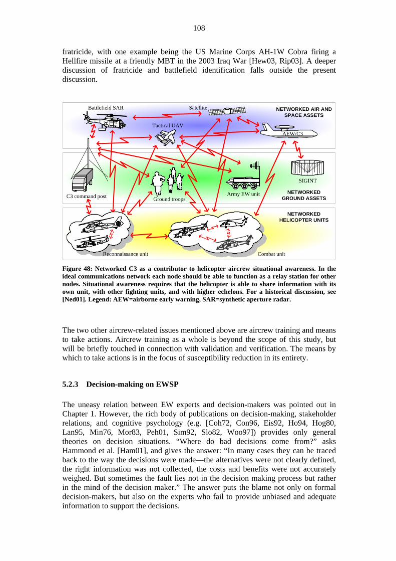
108
fratricide, with one example being the US Marine Corps AH-1W Cobra firing a Hellfire missile at a friendly MBT in the 2003 Iraq War [Hew03, Rip03]. A deeper discussion of fratricide and battlefield identification falls outside the present discussion.
Satellite
C3 command post
SIGINT
Battlefield SAR
Ground troopsArmy EW unit
Tactical UAV
Combat unit
AEW/C3
Reconnaissance unit
NETWORKED AIR ANDSPACE ASSETS
NETWORKEDGROUND ASSETS
NETWORKEDHELICOPTER UNITS
Figure 48: Networked C3 as a contributor to helicopter aircrew situational awareness. In the ideal communications network each node should be able to function as a relay station for other nodes. Situational awareness requires that the helicopter is able to share information with its own unit, with other fighting units, and with higher echelons. For a historical discussion, see [Ned01]. Legend: AEW=airborne early warning, SAR=synthetic aperture radar.
The two other aircrew-related issues mentioned above are aircrew training and means to take actions. Aircrew training as a whole is beyond the scope of this study, but will be briefly touched in connection with validation and verification. The means by which to take actions is in the focus of susceptibility reduction in its entirety.
5.2.3 Decision-making on EWSP The uneasy relation between EW experts and decision-makers was pointed out in Chapter 1. However, the rich body of publications on decision-making, stakeholder relations, and cognitive psychology (e.g. [Coh72, Con96, Eis92, Ho94, Hog80, Lan95, Min76, Mor83, Peh01, Sim92, Slo82, Woo97]) provides only general theories on decision situations. “Where do bad decisions come from?” asks Hammond et al. [Ham01], and gives the answer: “In many cases they can be traced back to the way the decisions were made—the alternatives were not clearly defined, the right information was not collected, the costs and benefits were not accurately weighed. But sometimes the fault lies not in the decision making process but rather in the mind of the decision maker.” The answer puts the blame not only on formal decision-makers, but also on the experts who fail to provide unbiased and adequate information to support the decisions.

109
One reason for “irrational” behavior in decision-making in the public sector on EW lies in industrial lobbying, and in political and personal aspirations. The decision process on the EWSP suite for the Nordic Standard Helicopter Program, presented in the case box below, is a blend of hidden agendas and non-EW issues—and also of trust in EW experts.112 Analysis of decision-making processes has attracted interest in the FSD community [Maa04], but it goes beyond the goals of the present work.
5.2.4 Conclusions on support functions Intelligence is the single most important support requirement of EWSP. Intelligence delays and reliability vary strongly, and this reflects in variations in the effectiveness of the EWSP suite. The second major EWSP support factor is the professionalism and resources of the EW support center. Reliability of the EWSP threat identification process depends on the quality of the MDF, which in its turn depends on the skill of the EW field officer that compiles the files and on the accuracy of tactical intelligence provided to him. The mission planning stage is of central importance also to the aircrew’s situational awareness and should be seen as a function that 112 A) The NSHP situation is more understandable when considering that the program ended up with four different helicopter types. Denmark selected the EH-101 whereas Finland, Norway, and Sweden chose the NH-90. However, the Finnish platform is the basic (German) troop transport version. Norway selected the naval version equipped for anti-submarine warfare. Sweden went for the troop transport version but changed the mission avionics suite for a Swedish-built one, and also equipped some helicopters for anti-submarine warfare in littoral waters. A common EWSP solution on these three NH-90 variants would have required three partly different installation efforts, whereas the end result was only two. B) The controversy surrounding the early stages of the Finnish helicopter program is described in some detail in Ahoniemi’s doctoral dissertation [Aho00]. Finnish views on problems in the multinational NSHP program have been expressed in Storgårds and Luoma [Sto01].
Case: Decision-making on the EWSP suite for NSHP helicopters. NSHP was a joint helicopter procurement program between Denmark, Finland, Norway and Sweden that peaked between 1999 and 2001. In an early stage of joint discussions Denmark made it clear that the country did not have resources to support two airborne EWSP suites and therefore intended to go for the EWSP solution on its F-16 fighter aircraft. What was not told was that Danish defense industry had a vested interest in this particular solution. The EW expert team of the other three nations made a unanimous recommendation on a solution that it saw as an advanced helicopter EWSP suite fulfilling—as the only offered solution—operational requirements of all three countries, providing opportunity for future cooperation between the nations, giving advantages in international operations, and having a price-tag in line with three of the four alternatives under consideration; while the risks were judged to be somewhat higher than for the competitors. Finland did the next move. Explaining that funding excluded anything but the cheapest EWSP solution it opted for the suite already installed by the helicopter manufacturer. Untold went a heated debate in 1997 between the Finnish Parliament and top-ranking military decision-makers, where the latter had made ill-founded statements on the cost of setting up a battlefield helicopter unit. The number of helicopters therefore had to be maximized at the expense of equipment. With Finland gone the pressure mounted on Sweden to select a solution that would help its defense industry to meet earlier offset obligations. Thus Norway alone selected the solution proposed by the EW expert team. Apart from some pressure on Finland to change its mind there was no bargaining in order to find a common solution.

110
continues throughout the mission. Accurate SA throughout the mission requires that the aircrew has access to real-time intelligence and reconnaissance data, and that individual helicopters themselves can contribute with reconnaissance data to a C3 network. Threat development is a major driving force of the W-curve. In order to provide flexible countermeasures to new threats the EWSP suite should, as far as possible, be software reconfigurable. However, the question of which factor, intelligence or technological progress, has a stronger impact on EW development is not answered by the W-curve. Decision-making processes are nonlinear and decisions are often formed by factors outside the realm of technical merits of the subject of interest. Chaos theory and multi-dimensional catastrophe theory could provide an approach to modeling these processes. However, bringing the discussion further, or attempting to model the decision-making process, is not beneficial for the present work.
5.3 EWSP systems factors
5.3.1 EWSP architecture and aircraft installation Benefits of an integrated EWSP suite were pointed out already in the 1960s [Ear78 p.22/20]. Two decades later Coleman [Col98] lists the following five incentives: (1) Correlation of sensor inputs—improved situational awareness. (2) Coordination of countermeasures—selection and control of CM, multiple threat prioritization, optimum CM strategy. (3) Single interface to mission system—glass cockpit compatibility. (4) Coordinated mission data recording. (5) Coordinated interoperability with radar, IRST and weapons. To the list should be added (6) reduced aircrew workload, particularly under the stress of combat flight [Lum02, Tra97]. Figure 49 shows the functional diagram of an integrated EWSP suite. The CNI system (communication, navigation, and identification) handles external communication, and is therefore the helicopter’s link to the C3 network in Figure 48. Means for updating the aircrew’s SA are multifunctional displays, aural warning signals, and voice communication. Supporting instruments are the CNI system, ownship sensors, on-board mission data files, and software for data fusion.113 The number of on-board data files can be quite large, as shown in Figure 50. With similar types of sensors and data files—the RWR and ESM systems, for instance—the risk of conflicting information increases. This brings up the idea of a standardized EWSP data file architecture to improve the situation. Since competing manufacturers cannot be expected to agree on a common solution, it should be standardized e.g. within NATO. The idea is obviously new, since earlier discussions have focused on integrating hardware structures on aircraft, particularly antennas and other apertures, which is motivated by the weight increase between uninstalled and installed avionics system [Ree94, Ric96].
113 The solution in Figure 49 is fictive, but similar ideas on integrated EWSP suites have been presented in Tran [Tran96, Tra97] and Fogh [Fog02].

111
Signal types:S1=CommandsS2=Threat dataS3= Lookthrough/blankingS4=Techniques assignmentS5=Mission data filesS6=Intercept dataS7=Status reportsS8=C/FD cueingS9=Requests/commandsS10=DIRCM cueing
EXTENDEDCONFIGURATION
LIMITEDCONFIGURATION
EWC
CNI systen
Stores
Weight on wheel(WOW)
Auralwarning
On-boardsensors
Embeddedtraining
Missioncomputer
RWR
LWR
Dispensers
Detectors
Tracker,jamminghead
FR AR
FL ALC/FD
DIRCM
DTU Recorder
Manualcontrol Blanking
Avionicsmuxbus
Avi
onic
sEW
SP s
uite
FR AR
FL AL
MWS
RFjammer &receiver FULL
CONFIGURATION
Multifunctionaldisplays
Antennas
Detectors
Antennas
S1
S2
S2
S3S4
S5 S6
S7
S2
S8
S9
S10
Legend:AL=Aft, leftAR=Aft, rightDTU=Data transfer unitFL=Forward, leftFR=Forward, right
Figure 49: Functional diagram of an integrated EWSP suite in three different configurations; the DIRCM is not controlled by the EWC (EW controller). Data links S1…S9 can also be implemented as an EW bus. The DTU is for loading mission data to the suite, the recorder for recording sensor and other data for post-mission analysis. Signals S3 and S9 are conflicting as shown; a decision must be made on which unit controls blanking during RF jamming.
Commsystem
CNIsystem
Navsystem
IDsystem
Status &navigation data
Status &received data
Status &
ID data
Situationalinformation
Controlinformation
Flightdata Threat &
status infoControl &CNI data
EWCdata
fusion
Status &threat data
C3 info
Threatdata
Countermeasures
LWRdata
fusion
Status &threat data
Threatdata
Techniques assignmentJammer status
RFjammer
C/FD
Threat data &DIRCM status
C/FD cueingC/FD status
MWSsignal pro-
cessing
Tech-nique
Jamming codes
Dispensesequence
On-boardsensors
Radar
Weapons& FCS
ESMsystemStatus & radar
target dataStatus &RF data
Status target &weapons data
Emitterdata
DIRCM
cueing
Terminology:”Status” refers to theoperational status ofthe system in question
C3 system
Threatdata
Threatdata
Missioncomputer
Display& control
Trackdata
Status &threat data
RWRdata
fusion
DIRCM
Threatsystem
identifierfile
EOB
MDF(RWR)
Missionplan
Techniquesfile
Sequencefile
Targettrackfile
Codefile
MDF(LWR)
MDF(ESM)
Figure 50: Block diagram emphasizing the potential number of on-board data files with a comprehensive EWSP/ESM solution. Correlating data from sensors with independent data files can lead to ambiguities and conflict situations. A standardized data file solution would improve the situation.

112
Platform installation is an engineering task which goes beyond the scope of the present work, but remarks on some issues that are not discussed elsewhere are motivated. First, sufficient aperture isolation is required and this can be a problem particularly for a small platform; ground reflections can also cause interferences. Second, data bus capacity requires careful consideration; particularly in threat evasion situations with rapid maneuvers. Third, cockpit MMI (man-machine interface) must observe pilot workload; for instance, automatic pop-up of threat information can impair the pilot’s ability to save the aircraft in high-threat situations. Fourth, air worthiness certification is required and this can incur significant costs [Zan99]. Location of apertures on the fuselage can be a major installation problem; Figure 51 shows locations on the AH-64 Apache Longbow.114
IR jammer transmitter(ALQ-144A(V)3)
Radar frequency interferometer(APR-48(V))
RF jammer receiverantenna (ALQ-136(V)5)
RWR spiral antenna(APR-39(V)1)
RF jammer transmitantenna (ALQ-136(V)5)
LWR detectors(AVR-2A(V)1)
RWR blade antenna(APR-39(V)1)
Chaff dispenser(M-130)
RWR spiral antenna(APR-39(V)1)
Figure 51: Location of EWSP apertures/subsystems and the RFI antenna on the AH-64 Apache Longbow [Anon02b]. For the installation of a proposed suite with DIRCM, see [Anon94b]. Since the ALQ-144 is a preemptive CM system it does not need an MWS. There are RF jammer transmit/receive antennas only in the forward sector.
5.3.2 Validation and verification
Definitions The present work distinguishes between the terms “validation” and “verification” in the spirit of ISO 9000:2000; while test and evaluation (T&E), and modeling and simulation (M&S) are means to reach the objectives of validation and verification. The relations are depicted graphically in Figure 52. Logically the sequence is to look first at verification and then at validation, since verification is connected to formal requirements but validation is related to less formal expectations. Verification is preceded by requirements specification, but this process will not be covered here. Verification and validation can both be directed at the EWSP suite per se, as well as at the installed suite. Validation has been described as “end-to-end verification i.e. meeting the user requirements in the operational environment” [Ste98 p.159] and encompasses not only the suite and platform but the total contribution of the EWSP suite to helicopter survivability. Validation, therefore, also covers threat systems and tactics, environmental factors, system responses, aircrew behavior, etc.
114 The question is not only about finding space for the physical location of apertures and dispensers. For instance, apertures should not be clogged by oil or snow, and the mechanical stress on the fuselage from flare ejections has to be considered.

113
VALIDATION
VERIFICATION
M&S T&E
Validation:Confirmation that therequirements for a specificintended use or applicationhave been fulfilled.
Verification:Confirmation thatspecified requirementshave been fulfilled.
M&S and T&E:Methodologies by whichvalidation and verificationobjectives are fulfilled.
Figure 52: Venn diagram showing the relations between validation, verification, M&S, and T&E. The objectives of validation are broader but less specific than those of verification.
Verification Verification of an EWSP suite encompasses three major steps:115 (1) Laboratory measurements in a test bench to verify the performance of the integrated EW suite. (2) Measurement range tests, including measurements in an anechoic chamber, of the installed performance of the EW suite [Ali97, Rob00, Smi94]. (3) Open air range (OAR) flight tests to evaluate EW systems in background, clutter, noise, and dynamic environments [Anon00b p.41, Boe95, Smi94], including the performance of the suite in peacetime signal environment. The skill of the customer is put on trial in the second step, which requires that necessary operational scenarios have been defined.116 However, it has been shown that test results of the three methods correlate poorly. Operator actions are a prime source of test variances, but they do not explain all inconsistencies. One speculation regarding verification of RF jammers is that nonlinear effects may produce chaotic behavior of the system and lead to unpredictable jammer performance [Tuc01a, Tuc01b]. The idea is intriguing, but earlier observations of ambiguity problems in EW testing and simulations could very well explain the nonlinearities [Boe95].117
Validation The problem of validation lies in substantiating the somewhat obscure “specified intended use” of the EW suite. As has been showed earlier, “rainbow threats” imply that almost any perceivable operational scenario is possible. Generic scenarios, building on national defense requirements with additional components from likely PSOs (peace support operations), are therefore an acceptable—although broad—compromise in defining the “specified intended use”. A realistic validation process 115 A) The three-step procedure described here is suitable for procurement of existing systems. DOD 5000.2-R [Anon96] defines a five-step T&E process, including four milestones, for cases when equipment are designed and built to specification. DOD 5000.2-R has a weakness (shared with US Air Force Manual 99-112) in concentrating on the acquisition phase and not supporting subsequent life-cycle phases. The problem is discussed in Sowell [Sow97]. B) A useful set of performance standards for wideband RF receivers is given in Tsui et al. [Tsu89]. Similar standards for EO systems are not known to exist. 116 A) According to Pywell and Stubley [Pyw96] an ideal EW equipment specification would in the pre-contract stage include time-histories of signals and functions as quantitative benchmarks for the aircraft and its installed EWSP suite: pulse density vs. frequency sub-band vs. time, instantaneous dynamic range requirements vs. time, number of simultaneous pulsed and CW emitters vs. time, etc. This level of detail, the paper claims, is rarely seen in specifications. B) The OAR stage covers aircrew behavior and is therefore a border case between verification and validation. 117 Charland and Pulsifer [Cha02] reports of simulations on cross-polarization jamming on a generic terminal-phase seeker, and have found evidence of chaos and fractals in the results.

114
requires that the helicopter with its installed EWSP suite is flown under measurable conditions against simulated and/or real threat systems on an OAR. If possible, OAR tests should be repeated before a campaign, with the test range instrumented to the best possible match with the scenario to be expected.
Modeling and simulation Modeling and simulation used on its own has the risk of producing distorted results. Combined with test and evaluation the methods can support each other. Figure 53 shows M&S support to T&E at various EW development stages, to produce predictions of overall system performance. Slightly different model approaches are the cyclic M&S/T&E processes described in [Anon95b, Anon96].
Use M&S to translate required systemcapabilities into measures of effectiveness andmeasures of performance
Use M&S to predict approximateantenna RCS and antenna patterns tohelp plan test. Use measured resultsto update digital M&S.
Use M&S to define scenarios andset the configuration for test. Predictcomponent/subsystem performance,and use measured results to updatesystem model.
Use M&S to define scenarios and setthe configuration for test. Predictexpected system performance, anduse measured results to updatesystem model.
Use M&S to define scenarios andset the configuration for test. Predictexpected system performance, anduse measured results to updatesystem model.
Use M&S to define scenarios and setthe configuration for test. Predictexpected system performance, anduse measured results to updatesystem model.
Use measured data to predict receiversensitivity and jammer power outputrequirements. Results assist planninglater testing. Identify problem areas.
Use M&S to forecast performance inHWIL and design HWIL testing formaximum productivity. Identifyproblem areas.
Use updated M&S to forecastperformance in flight test. Useresults to identify problem areas andto design flight testing.
Use updated M&S to forecastperformance in scenarios beyondHWIL capabilities. Use results toidentify problem areas and designtests at ISTF and flight tests.
Use updated M&S to extrapolate andextend results from testing forpurposes of evaluating measures ofeffectiveness.
Pred
ictio
ns o
f ove
rall
syst
em p
erfo
rman
ce
TEST REQUIREMENTS
Measurement facilitiesAntenna patterns, antenna
isolation, RCS, etc.
System integration labDetermine HW and SW
interactions
HWIL facilityDetermine system under
test interactions withenvironment
Installed system testfacility (ISTF)
Determine functionality ofsystem installed on aircraft
Flight test facilityConfirm effectiveness ofsystem in realistic flight
conditions
Figure 53: Support of digital M&S to T&E at various EW development stages. The use of M&S to define scenarios can be noted. Adapted from [Anon00b p.33]. The process focuses on RF aspects of EWSP and needs modification to fit EO equipment. Generic models can be used to advantage in M&S of infrared CMs [For01].
Modeling and simulation is frequently used in mission analysis, as indicated in Figure 46, and in the “flight test facility” stage of Figure 53. An important issue to platform survivability is the probability of kill (Pk) during a mission (cf. Table 5). Figure 54 shows one approach to estimating the minimum probability of kill (min-Pk) for a flight leg. The idea is to calculate a basic-Pk (no countermeasures) that acts as reference for the flight leg and then minimize Pk with a mixture of threat elimination and evasion measures. Since threat avoidance and elimination actions will influence the threats, the calculated basic-Pk value is valid only for a limited flight leg. In reality alternative legs will have to be investigated in order to find the min-Pk for the leg in case; with consideration for limitations imposed by flight corridors, flight formations, etc. As with all simulations the level of detail in the M&S process has to be judged against the additional benefit given by the details.

115
BASIC PkANALYSIS
SUPPORTMEASURES
Min-PkANALYSIS
Computebasic Pk
envelopes
Detectionranges
Platform flightwith and withoutmaneuvers vs.threat kinematics
Basic-Pk
Computedetection
ranges
Radar, EO,visual, others
Air threatdata
Platformdata
Ground threatdata
Computetime-to-go,range-to-
go
Data on threatelimination assetts
Data on threatelimination assettsData on threat
avoidance assettsData on threat
avoidance assetts
Computeminimum
Pk
Definemix of
susceptibilityreductionmeasures
Data onCM assets
Time-to-go/range-to-go
Air threat:* Type* Velocity* Altitude* Course* Maneuvers* Signatures
Platform:* Type* Velocity* Altitude* Course* Maneuvers* Signatures
Ground threat:* Type* Fire doctrine* Weapons* Signatures
Threat elimination:* Sensors* Attack systems* Weapons* Communication
Threat avoidance:* Flight plan/route* Reconnaissance/C3* Flight tactics
Other signatures:* Society* Friendly forces* Battlefield
Signaturedata
Threat evasion:* Warning systems* Maneuvers* Decoys* Jammers
Signaturedata
Data onCM assets
Mix ofassets
Data onCM assets
Definenew mix
Mix ofassets
Min-Pk
Line-of-sight:* Multipath* Terrain* Clutter* Atmosphere* Others
LOS data
LOSdata
Figure 54: Simulation of minimum probability of kill (Min-Pk) for a mission leg. Apart from the shown Pk iteration (“define new mix”), the full simulation requires different leg alternatives to be evaluated and the influence of threat avoidance and elimination actions to be fed back to the Basic-Pk calculation. Adapted from Arcidiacono [Arc87].
Test and evaluation Three verification types were mentioned above: test bench laboratory measurements, measurement range tests, and OAR flight tests.118 In addition Figure 44 covered some T&E resources of the EWSC. Table 39 reviews the benefits of M&S, ground tests, and OAR test flights. A more detailed discussion is presented in Appendix 1, Table 1-4. The ground tests in Table 39 split into three main groups: test bench laboratory measurements on uninstalled EWSP suites (or individual subsystems), indoor tests on installed suites, and outdoor tests on installed suites. Anechoic chambers provide an electromagnetically controlled test environment for precision RF measurements, which is of importance for repeatability and for testing classified signal parameters. Outdoor measurement ranges provide less controlled environment, and are also influenced by weather conditions, but are less expensive than anechoic chambers. In addition, outdoor ranges allow testing with all aircraft systems on, which is not possible in an anechoic chamber. [Ali97, Smi94] The cost of reverberating chambers is lower than that of anechoic chambers. Reverberating chamber measurement on helicopters has been investigated in at least one case [Joh98a]. The method is, however, feasible only for electromagnetic compatibility and interference (EMC/EMI). The alternative to OARs is to test airborne equipment against ground equipment during ordinary military maneuvers. This is a low-cost solution that produces some results, but its true value remains uncertain: Emitter control is scanty, the telemetry outfit is usually poor, and the measurements cannot be repeated to validate results. Military maneuvers attract the interest of other nations, and are monitored by foreign SIGINT assets, and the type of scenarios and emissions must be limited. 118 Requirements on open-air testing of IRCM systems have been outlined in a recent US DOD report [Anon04b]; OAR scenarios for fixed-wing applications are presented in chapter 7 of [Bru95].

116
M&S Ground tests OAR flight tests Test factors EW system — — — number Very good Good Fair credibility Fair Good Very good Threat system — — — number Very good Fair Fair quality Fair Good Very good Tactics — — — develop Good Very good Fair evaluate Fair Fair Very good Identify sensitivities Very good Good Fair Configuration flexibility Good Very good Fair Environmental realism Fair Fair Good Operator interaction N/A Fair (threat) Good (threat and friendly) Systems interaction N/A Fair Good General factors cost Lowest Moderate Expensive capacity High Moderate Limited application timeliness Hours/days Weeks/months Months credibility Low Moderate High
Table 39: Comparison of the advantages and limitations of three V&V methodologies. Adapted from Wright [Wri93].119 Ground tests can be performed on either uninstalled or installed EWSP suites; for installed suites an outdoor test site is less expensive than an anechoic chamber but outdoor measurements bring the risk of compromising classified system parameters.
Dedicated OARs focused on EW testing are populated with high fidelity threat simulators in addition to basic range instrumentation and airspace control capabilities. Threats are reproduced by fixed and mobile simulators, as well as by operational materiel. [Anon85, Anon00b p.41, Kin04, Wod01]120 A drawback for helicopter EWSP is the less developed state of EO than that of RF test equipment. IR guided missiles are a particular challenge, since both IR and UV radiation should be produced with kinematic and intensity correctness [She01]. Figure 55 outlines a procedure for conducting an OAR test. In the procedure a predictive model of the test is first developed, next the test flight is conducted according to the “script” of the model, and finally test data are evaluated and performed with predictions. 121 If unaccounted discrepancies emerge the model must be change or the test be repeated.
119 A) The information in Wright [Wri93] is based on Farmer, W.D., Nagel, J.F.: Electronic Warfare System Operational Test and Evaluation, final report, Air Force Test and Evaluation Center, Kirtland AFB, NM, 1980; and on Anon: Test Process for Electronic Combat Systems Development, vol. 2: Report and Appendices, USAF Ad Hoc Group, Andrews AFB, Washington DC, AFSC/TE, 10 October 1982. These reports have not been available for the present work. B) The term “capacity” refers to how many enemy and friendly resources can be presented in a scenario, “timeliness” refers to how soon answers to key questions can be provided, and “credibility” to the degree to which users believe that the tool is representative of the system under test [Wri93]. 120 An example of a large OAR is the Polygone area, spreading over 20,000 km2 across the Franco-German border. The facility has three major tasks: (1) Development, testing, and verifying tactics in the face of actual or simulated SAMs. (2) Assessing and validating airborne countermeasures equipment. (3) Improving aircrew skills in a dense threat environment. Threats are reproduced by fixed and mobile simulators, as well as by operational materiel. The effectiveness of the Polygone facility has been enhanced by the expertise of former East-German military personnel, who provide insight into operational procedures of the former Soviet Union. [Wod01] 121 The process can be compared with the predict-test-compare philosophy in [Anon95b].

117
ModelEWSP
behavior intest flight
Friendlyemissions
Equipmentperformance
Signatureparameters
Topographicaldata
Analyzetest flight data
& comparewith modelPredicted
performance
Performanceparameters
Measuredperformance
Signatureparameters
Preparetest range
Plan testflight
Conducttest flight
Ready
Ready
Testdata
OAR testresults
Testrequirements
Aircraftsignatures
EWSP suiteperformance
ENVIRONMENT
TESTFLIGHT
AIRCRAFT
Signatureparameters
Emissiondata
Enemydeployment
Friendlydeployment
Test rangetopography
Telemetryrequirements
COMBATSCENARIO
Meteorologicaldata
Definetelemetryrequire-ments
Hostileemissions
A
B
Weatherdata
Civilsignatures
Figure 55: Example of an OAR test process. The process has two feedback loops between M&S and T&E (A and B). Maneuvers and other aircrew actions are not part of the modeling and introduce a discrepancy that has to be observed when evaluating test data. The resemblance with Figure 46 can be noted.
Aircrew training A benefit of OARs is the realistic aircrew EW training opportunity they offer [Wod01]. However, due to the cost of OAR flights they cannot be used as a standard EW training tool. A lower cost combat training solution has been proposed in the form of a data management system between multiple low-flying players, and a high-flying control aircraft transmitting simulating threats and evaluating engagement outcomes. EW tests could form one part of these encounters. The solution is also claimed to improve realism compared with OAR training by switching off “killed” threats and providing correlation between countermeasure initiation and evasive maneuvers. [Ras98] A yet simpler training simulator is an on-board terminal for injecting predetermined threat scenarios into the aircraft’s avionics [Ras90]; this idea easily transforms to an embedded software training module, as indicated in Figure 49. A shortcoming of the simpler solutions is that they are limited to the training role and provide no information for EWSP assessment.
5.3.3 Conclusions on EWSP systems factors The avionics architecture of the helicopter directly influences EWSP effectiveness, aircrew situational awareness, and the helicopter’s ability to contribute to information sharing within a networked C3 solution. Management of on-board data files has not received sufficient attention and is therefore a bottleneck to the efficiency of the helicopter’s integrated avionics assets.

118
Platform installation requires careful attention to details. Verification and validation are costly processes but necessary to reach a cost-effective level of susceptibility reduction. Both modeling and simulation, and test and evaluation methodologies are needed to fulfill verification and validation objectives. Due to the cost of validation small countries will remain dependent on friendly nations—or on alliances—for adequate verification and validation of their EWSP suites, and to provide aircrews with sufficiently realistic training on operations in high-threat environment.
5.4 Interactions and quantification
5.4.1 Interactions The question of threat and countermeasure interactions was discussed in Section 4.3.5. This discussion can be extended to all types of interactions in processes related to EWSP. Electromagnetic compatibility between friendly forces is one type, as was demonstrated during the 1999 NATO campaign in Kosovo when German Tornado aircraft were unable to fulfill SEAD missions due to jamming by American EA-6B Prowler aircraft [Put02b]. Interactions between hard-kill and soft-kill self-protection measures in the naval case have been pointed out in Thé and Liem [Thé92, Thé95]. Figure 56 shows a polygon model of interactions, based on an idea in [Thé92]. Both polygons contain k=8 nodes, which gives k(k-1) /2=28 interaction routes if all links are of relevance. Assuming that each node of the top-level polygon leads to a lower-level polygon with eight nodes, the number of isolated interactions on the lower level is 224. Continuing this discussion quickly uncovers an unmanageable problem complexity. The analysis therefore has to focus on the most important interactions—in line with requirements on aggregation in modeling and simulation. Adding to the difficulties for the EWSP suite is the fact that threat signals often are orders of magnitude weaker than interfering signals.
EWSP suite
Avionics
Other on-board
emitters/receivers
Platformsignatures
Maneuvers
Wingman
Man-madesources
Naturalsources
RWR
MWS
LWR
Blanking
DIRCM
RFJ
Expend-ables
Computers& busesCounter-
measures
Cross-interactions
Internal interactionsExternal interactionsReceiver/transmitter
Installationassets
Receivers
TOP-LEVEL INTERACTIONPOLYGON
LOWER-LEVEL (EWSP SUITE)INTERACTION POLYGON
Figure 56: Interactions on different levels interpreted through polygons. Only one lower-level polygon and no levels beyond that are shown. Investigating all interaction alternatives becomes unmanageable, which indicates that complete validation of the EWSP suite is impossible.

119
5.4.2 Quantification There is need for a common base on which to evaluate the true value of an EWSP suite. The following are some value-related questions that should be answered [Joh98b]: (1) Which is the primary objective, to fight the enemy or to limit one’s own losses? (2) Which is the value of survivability measures that aid in minimizing own and maximizing enemy losses, but simultaneously increase the time needed to fulfill the primary task? (3) Which EWSP solution is to prefer, one that gives low losses assuming that both system and operator function optimally or one that gives somewhat higher losses but is robust and functions under all conditions? (4) How should one evaluate indirect effects, e.g. the value of survivability means that discourage the enemy from conducting an operation or forces him to select a secondary objective instead of the primary one? (5) How does one evaluate the psychological effects of an EWSP suite? From these questions Johansson [Joh98b] concludes that it is impossible to give a definite answer on how to quantify the value of an EWSP suite. The conclusion is incorrect in the sense that quantification is quite possible (e.g. Delphi and AHP methods), the problem is the reliability of the quantified information.
5.5 Conclusions on EWSP systems and support issues The importance of scientific and technical intelligence to EWSP is overwhelming. A country either has an effective intelligence apparatus of its own or depends on other nations for basic information required for the effectiveness of EW resources. This comment is equally valid for the EWSC organization, which in the present work covers EW research, analysis of threat equipment, EW acquisition support, generation and management of emission and countermeasures files, verification and validation of EWSP systems, aircrew EW training, etc. Decision-making on EWSP shows similarities with comparable functions within the public sector. “Rational” processes are overruled by political and personal interests, and hampered by communication problems between experts and decision-makers. A further investigation of problems related to decision-making must be left for future research, but the discussion shows the difficulties in one of the central issues of this study: communication between stakeholders. Thorough EWSP validation is a costly infrastructure process, beyond the reach of independent small countries with limited defense budgets. This brings EWSP alternatives on the political agenda: A country either has to increase or reallocate defense funding to support acquired high-tech equipment, to become reliant on other nations for the support, to make acquisitions that in reality are a waste of money due to lack of required life-cycle support, or to consciously forsake platform protection by EWSP.

120

121
6 SYNTHESIS OF THE HOLISTIC VIEW
6.1 The legacy of earlier chapters The earlier discussion leads to hypothesize a preliminary holistic view for susceptibility reduction of battlefield helicopters through EWSP; shown by the causal loop diagram (CLD) in Figure 57. The scope of this view is much wider than the guideline in Section 3.3.1. In the model susceptibility reduction (EWSP effectiveness) rests on four “pillars”: First, on intelligence that provides information on which survivability in general and countermeasures in particular are based. Second, on the importance of survivability in the defense budget; this defines allocation of resources and acts as the general constraint factor. Third, on scientific and technical (S&T) resources that facilitate transformation of intelligence into practical countermeasures. Fourth, on the importance of survivability in doctrine and tactics that governs conditions under which the EWSP suite should function. The engine of change lies in the exogenous group of threats, scenarios, and technology. Three questions from the earlier discussion need to be considered: First, how can the status of EWSP be improved in the eyes of decision-makers (= importance in defense budget)? Second, which role can a high-grade EWSP suite have in intelligence? These questions are indicated by the red arrows in the figure. Third, is the preliminary model correct and does it represent a true holistic view?
Threats, scenarios, technology
EWSPeffectiveness
importance ofsurvivability in defense
budget
intelligenceeffectiveness
importance ofsurvivability in doctrine
and tacticsEWSP S&Tresources
Figure 57: Preliminary view of major factors in susceptibility reduction of battlefield helicopters through EWSP. Effectiveness rests on four “pillars” (blue/bold links). The driving force of the model is the exogenous group of threats, combat scenarios, and technology. Interactions are mainly one-way (blue links), and delays in implementing changes are long, but questions on the status and role of EWSP introduce feedback links (red links).

122
Figure 58 reviews earlier discussed mission-related susceptibility factors and their relations in more detail, with the threat-intelligence interaction of Figure 57 as the starting point and the term “intelligence” used in the broad sense of information gathering and analysis, not only as the duty of a specialized organization. The arrows in Figure 57 represent dynamic changes, whereas Figure 58 takes a snapshot view that disregards resources and doctrinal questions although they are inherently present. The central implications of Figure 58 are:
1. Intelligence works on different temporal levels. In the long term it supports the definition and acquisition phase, in the medium term it supports library production and the continuing validation process, and in the short term it supports missions.122
2. Intelligence and the C3 network link the helicopter to the wider battlespace, only local information is produced by on-board sensors. Analysis of the EWSP suite alone, or as part of the helicopter’s avionics suite, requires introduction of artificial boundaries.
3. The trio of susceptibility mechanisms of threat elimination, threat avoidance, and threat evasion are interwoven through common assets and objectives, and therefore also influence each other. Analysis of any single mechanism requires introduction of artificial boundaries. Consequently the EWSP has the potential to influence all three mechanisms of susceptibility reduction (cf. Figure 13).
4. Situational awareness has a local dimension residing in the aircrew of an individual helicopter, and a holistic dimension that extends throughout the C3-networked battlespace.
5. The EWSC strongly influences threat avoidance and evasion through its involvement in EWSP V&V, as well as in emission and CM data file generation and management. The influence on threat elimination depends on the geolocation capability of the EWSP suite.
6. The effectiveness of the EWSP suite is the intersection of its intrinsic hardware/software (HW/SW) potential, of its validated performance and of mission-specific MDFs. Scenario changes impose requirements on revalidation, but since every scenario cannot be validated a decision has to be made on which ones to validate and which ones to bypass.
7. Threat elimination depends heavily on friendly support assets—DEAD and support jamming—and requires considerable planning. A more flexible response is achieved if the mission plan can be altered during mission execution.
A main conclusion of these implications is that network centric warfare capability has a positive effect on helicopter survivability and that the EWSP suite can contribute to this capability. Figure 58 does not resolve the earlier question whether the engine of EWSP development lies in the threats themselves or in technological progress. The figure does point out a major limitation of stealth technology: Stealth is effective only for threat avoidance, one of three susceptibility reduction mechanisms.
122 Note that here the term “intelligence” embraces reconnaissance and surveillance.

123
Thr
eat
elim
inat
ion
On-
boar
dw
eapo
ns
Fire
supp
ort
DEA
D
Supp
ort
jam
min
g
Sign
atur
ere
duct
ion
On-
boar
dse
nsor
s
EWSP
* su
ite
CN
I sys
tem
othe
r sen
sors
topo
grap
hy
atm
osph
ere
situ
atio
nre
port
s
C3
netw
ork
Task
ord
er
Valid
ated
p’fo
rman
ce
EW fi
eld
offic
er
HW
ILca
pabi
lity
Scen
ario
s
Inte
llige
nce
Leg
end:
CN
I=co
mm
unic
atio
n, n
avig
atio
n,
iden
tific
atio
nD
EAD
=des
truct
ion
of e
nem
y ai
r
def
ense
EWSC
=EW
supp
ort c
ente
rFC
S=fir
e co
ntro
l sys
tem
HW
IL=h
ardw
are-
in-th
e-lo
opM
&S=
mod
elin
g an
d si
mul
atio
nO
AR
=ope
n ai
r ran
geT&
E=te
st a
nd e
valu
atio
nV
&V
=ver
ifica
tion
and
valid
atio
nSUSCEPTIBILITYREDUCTION
Enem
ysi
gnat
ures
Battl
efie
ldco
nditi
ons
FCS
Geo
loca
tion
capa
bilit
y
Obs
tacl
eav
oida
nce
Mis
sion
plan
ning
Situ
atio
nal
awar
enes
s
Plat
form
agili
ty
Airc
rew
skill
EWSP
*ef
fect
i’nes
s
Enem
yac
tions
T&E
capa
bilit
y
Figu
re 5
8: F
acto
rs c
ontr
ibut
ing
to h
elic
opte
r m
issi
on s
usce
ptib
ility
. The
figu
re is
by
nece
ssity
sim
plifi
ed a
nd h
as a
nar
row
er o
utlo
ok th
anFi
gure
57.
The
EW
SP b
lock
(*) h
as b
een
split
to e
ase
draw
ing.
The
term
”si
tuat
ion
repo
rts”
cov
ers
EO
B (e
lect
roni
c or
der
of b
attle
) and
othe
r ta
ctic
al in
telli
genc
e us
ed fo
r m
issi
on p
lann
ing.
”R
eal t
ime
inte
llige
nce”
cov
ers a
ll ty
pes
of in
-flig
ht in
form
atio
n th
at a
re r
ecei
ved
over
the
C3
netw
ork
(cf.
Figu
re 4
8). V
alid
atio
n is
inte
rpre
ted
in it
s br
oade
st s
ense
and
has
als
o an
influ
ence
on
airc
rew
ski
lls. H
WIL
cap
abili
tyre
quir
ed fo
r th
reat
dat
a fil
e ge
nera
tion/
test
ing
is se
para
ted
from
gen
eral
T&
E c
apab
ility
. Bei
ng a
tree
dia
gram
, the
figu
re c
ould
be
turn
edin
to a
n ac
yclic
Bay
esia
n be
lief n
etw
ork
for
quan
titat
ive
anal
ysis
[Sta
04].
Thr
eat
avoi
danc
e
Thr
eat
evas
ion
Frie
ndly
/neu
tral
sign
atur
es
Cou
nter
-m
easu
res
Man
euve
rs
Flig
ht ro
ute
V&V
M&
Sca
pabi
lity
Req'
men
tsdo
cum
ents
EWSC
Thre
at/
mis
sion
data
file
s
Real
-tim
ein
telli
genc
e
Mis
sion
repl
anni
ng
Mut
ual i
nflu
ence
s
Mut
ual i
nflu
ence
s
THR
EATS
Figure 58: Text in figure.

124
One approach to susceptibility is presented in Ball [Bal03 p.54/fig.1.1]. When comparing the ideas of Ball to those presented in Figures 12, 13, 57, and 58, the marked difference is in the emphasis on financial resources, intelligence, and EWSP support assets. (The question of resource allocation between EWSP and non-EWSP survivability measures has not received attention in the open literature and is obviously solved on an ad hoc basis: Mission planning has to live with whatever support assets are allocated by the task order, regardless of whether the aircraft are protected by EWSP or not.123) It must therefore be concluded that a holistic view on EWSP can be based on different approaches and that the outcome will differ. This invariably leads to thoughts of a suprasystem for EWSP (cf. Figure 2), not unlike von Bertalanffy’s quest for a General System Theory [Ber68]. However, the General System Theory has not materialized, and pushing such ideas too strongly for EWSP may well be counterproductive.
6.2 Aspects of holism in the EWSP context
6.2.1 Introduction The term “holistic view”—which in Section 1.3.4 was defined to be a surrogate for the term “systems thinking view”—is central to the present work. Section 6.2 attempts to identify a bounded domain that is sufficiently unambiguous and has holistic hallmarks to be used as a guideline for investigating EWSP of battlefield helicopters. The search concentrates on two approaches, a temporal and a hierarchic approach that together would form a bounded time/hierarchy domain.
6.2.2 Temporal bounds The time scale of EWSP-related events vary from at least 10-11 seconds, the approximate period time of a 94 GHz carrier, to 30 years (l109 seconds), the time scale of an EWSP system from design initiation to decommissioning. EWSP time scales therefore cover 20 orders of magnitude—more if optical carriers are considered. Various EW interest groups look at different parts of the total time scale, as depicted in Figure 59. The figure shows that the lower end of the time dimension covers physical, logical and similar factors, which are of main interest to EW systems engineers. The upper end of the time dimension is concerned with planning, acquisition and missions; i.e. events that are of prime concern to military planners and upper-echelon decision-makers. The range 1…103 seconds is a transition region which is of main concern to individuals focusing on platform performance, engagements, and survivability. 123 In light of the discussion around the successor to the US EA-6 Prowler it can be asked if optimization is possible at all: Overoptimistic expectations on stealth technology caused a deficit in US stand-off jammer capability (cf. Section 1.2.2). Only when the limitations of stealth became obvious did plans for a successor to the Prowler become urgent. It is difficult to find an optimal mix between stand-off jamming, attack aircraft, artillery, escort helicopters, on-board weapons, and EWSP in helicopter operations—especially under the uncertainties of the battlefield. Despite this the lack of an attempt to understand the basic mechanisms for optimization is striking.

125
Tim
e sc
ale
of E
W in
tere
st g
roup
s
Tim
e sc
ale
of E
WS
P s
yste
ms
Tim
e(s
econ
ds)
EWSP
syst
ems e
ngin
eer
EWSC
scie
ntis
t/eng
inee
r
Airc
rew
EW p
rogr
amm
anag
erDec
isio
n-m
aker
Trai
ning
off
icer
RF
carr
ier
EO carr
ier
Lase
r pul
sew
idth
Noi
sem
odul
atio
n
PRI
Flar
etim
e
RF
puls
ew
idth
Scan
tim
e
RF
dece
ptio
npe
riod
Targ
eten
gage
men
ttim
e
Mis
sion
exec
utio
n Tact
ical
plan
ning
Thre
at fi
leup
date Inte
llige
nce
feed
back
Acq
uisi
tion
proj
ect M
ilita
rypl
anni
ng c
ycle
Doc
trine
deve
lopm
ent
Org
aniz
atio
nal
Phy
sica
l-Tec
hnic
al
Figu
re 5
9: T
ime
scal
es o
f var
ious
EW
SP in
tere
st g
roup
s (t
op) a
nd o
f EW
SP s
yste
ms
and
supp
ort f
unct
ions
(bot
tom
). A
dapt
ed fr
om W
iega
nd[W
ie91
pp.
31-3
3]. B
elow
one
sec
ond
phys
ical
and
tech
nica
l iss
ues
dom
inat
e th
inki
ng. A
bove
som
e 10
00 s
(app
rox.
15
min
utes
) org
aniz
atio
nal
issu
es d
omin
ate
(pla
nnin
g, in
telli
genc
e, d
evel
opm
ent,
mis
sion
s, et
c.).
The
tim
efra
me
1 to
100
0 s
is a
shi
ft r
egio
n do
min
ated
by
ques
tions
of
obst
acle
avo
idan
ce, e
ngag
emen
ts, E
WSP
eff
ectiv
enes
s, cr
ew p
erfo
rman
ce, c
ockp
it ev
ents
, etc
.
10-9
10-6
10-3
100
103
106
109
One
seco
ndO
neye
arO
neho
ur
10-1
2
One
min
ute
One
wee
k
Figure 59: Text in figure.

126
Based on Figure 59, events lasting 103 seconds (approx. 15 minutes) or longer can be selected candidates for the holistic definition in the temporal sense. This time limit coincides incidentally with the definition of a mission element in Dickmanns and Fürst [Dic98], which seeks to define a multiple scales representation of time for mission performance at several temporal levels. The 15 minute-definition would make individual mission elements the shortest time elements to observed in a holistic view; the upper limit are processes like the EWSP life cycle and the military long-term planning period. Physical and technical details, individual pilot actions, etc. would be disclosed, since they easily clutter a holistic discussion on EWSP with excessive detail.
6.2.3 Hierarchic bounds Luttwak [Lut87 pp.69-70] defines four strategic levels: the strategic, operational, tactical and technical levels. The present work needs a finer hierarchic grading. For that purpose a hierarchic grading of strategic, operational, tactical, entity, technical, logical, and physical levels is proposed in Table 40.124 There are three reasons for selecting this particular solution: First, in addition to ordinary strategic hierarchies it brings in both technical and human aspects of EWSP. Second, its conceptual similarity to the ISO OSI hierarchy of communication systems is recognizable. The hierarchy is therefore familiar to the military and electronics communities alike.125 Third, the model has an ideological resemblance with the onion skin model of Fig. 12 (solve problems outside-in, or top-down in Table 40), and also with the mission oriented analysis methodology proposed in Coyle et al. [Coy89, Coy99]. Based on Table 40 candidates for the holistic definition in the hierarchical sense are mission elements on the entity level and above. This definition would mostly be concerned with problems from the sphere of operational officers, national assets, logistics, and management; while excluding technical details.
6.2.4 The fallacy of the bounded time/hierarchy domain When combining the temporal and hierarchical candidates for the holistic definition, the shaded rectangle in Figure 60 emerges. This will be referred to as the bounded holistic time/hierarchy domain of EWSP. It is attractive in defining a clear-cut domain for further investigation; it also highlights the area of interest of most EWSP stakeholders. The area of major interest to the EW community is indicated by the oval, and it emphasizes the communication problems in EWSP: Interests of stakeholders are located in diagonally opposite corners of the figure. 124 The term “entity” is adapted from Technology for the United States Navy and Marine Corps, 2000-2035, Volume 9 Modeling and Simulation, National Academy Press, 1997, p.72. Its usage by the Navy and Marine Corps is in the context of hierarchic families of models (strategic, operational, tactical, entity), similar to Luttwak’s definition of strategic levels. In the present work the term “entity” points to the helicopter, either singly or as member of an operational unit (entity). 125 In EW modeling and simulation a four-level construction has been defined by US authorities: Level I, engineering; Level II, platform; Level III, mission; and Level IV, theater or campaign [Anon95b]. For instance, the Joint Modeling and Simulation System (JMASS) covers the two lowest levels of this hierarchy [San00].

127
HOSTILE FRIENDLY Hierarchy level Threat component EWSP component Support component
Strategic Scientific, engineering, and economic capability to develop and field new threat systems, and the will to do so.
Research on CMs to potential threat systems and technologies, training and validation.
Intelligence on the actions and intentions of the potential enemy, and of threat capabilities.
Operational Decision to deploy threat systems and capabilities to conflict area.
Requirements on EWSP configuration(s) and emission data files.
Intelligence on enemy deployment, intentions and capabilities. Tasking.
Tactical Decision to group threat systems and capabilities to mission area.
Mission planning, compilation of mission-specific MDFs.
Intelligence on enemy grouping; mission planning with support.
Entity Decision to use threat systems against friendly assets.
Aircrew SA, support to threat avoidance & elimination, threat evasion.
Reconnaissance and real-time C3 support for mission SA, SEAD and other fire support assets.
Technical Performance of threat systems and technologies, sensor coverage & C3 delays, engagement timelines.
EWSP systems and technologies, FOV, POI, AOA, sensitivity, Pd, Pfa, maneuvers.
Preemptive only: intelligence, R&D, V&V, aircrew training, etc.
Logical Engagement tactics, spatial & temporal signal distribution, modulation types.
Tactics, temporal & spatial CM distribution, modulation types.
Preemptive only: intelligence, R&D.
Physical Time, space, energy, speed, frequency, BW, acceleration, power.
Time, space, energy, speed, frequency, BW, acceleration, power.
Preemptive only: R&D.
Table 40: Proposed EWSP hierarchy. The fourth strategic level according to Luttwak [Lut87 pp.69-70]—the technical level—is divided into the technical, logical and physical levels. The entity level covers mission events on the platform level, i.e. the human dimension in EWSP. The transition region in Figure 59 overlaps the border between the entity and technical levels. Considering the short engagement timelines of helicopters there are essentially no effective support measures once an engagement commences (shaded cells).
Despite the attractive idea of a bounded holistic domain, a critical analysis reveals that the interpretation is oversimplified, as exemplified by the events depicted in Figure 60: Assume that the strategic/operational SIGINT asset intercepts a new threat parameter—an event that may last only a short while. The information is delivered to the EWSC where it is analyzed and identified as a new threat mode. The information is subsequently used in threat and countermeasure techniques files on the helicopter and in the data files of the SIGINT aircraft as an identified emitter mode. If the implications of the observed threat mode are serious enough, an EWSP modification program will have to be initiated.126 A similar chain of events is possible if the EWSP suite of the helicopter records emissions with sufficient fidelity and the data can be used to update threat libraries. It is therefore obvious that the bounded time/hierarchy domain is critically dependent on its environment, and that a strict division into holistic and non-holistic domains is too restrictive. A true holistic view must accept interactions on different temporal, hierarchical and other levels, and between different survivability mechanisms.
126 Incidents of this kind are reported e.g. in [Bro99, Gri00].

128
Level 7:Strategic
Level 6:Operational
Level 5:Tactical
Level 4:Entity
Level 3:Technical
Level 2:Logical
Level 1:Physical
HIERARCHYLEVELS
TIME10-9 10-6 10-3 100 103 106 109
SIGINTIntercepts
MDFs
MDFs
Intercepts
MDFs
EW support center (EWSC)
EWSP
mod
ifica
tions
Bounded time/hierarchy domainof EWSP
Region of interestto EW community
Figure 60: The bounded time/hierarchy domain of EWSP, the EW community's area of interest, and interactions opposing the interpretation of a strictly bounded holistic view on EWSP of battlefield helicopters.
In conclusion, the holistic view can take the bounded domain in Figure 60 as its starting point but must accept the necessity for interaction outside this domain. The definition below is therefore taken as the holistic view of EWSP of battlefield helicopters. The consequence of open bounds is that the holistic view remains partly open to interpretation. Definition 1:
6.3 Revisiting the tentative idea for the present work Sections 6.1 and 6.2 contain the essence of the holistic view on EWSP of battlefield helicopters (recalling, however, that Figure 57 has been discussed only partly). Before a more detailed discussion it is motivated to compare the picture so far with the tentative idea of Figure 3. The comparison reveals the following:
1. Technical and scientific details in Figure 3 are not of prime concern for the holistic view, although they can work as “glitches” with impact on the bounded time/hierarchy domain. The importance of verification and validation has been amplified.
The holistic view of EWSP of battlefield helicopters focuses on the bounded time/hierarchy domain and events or actions that interact with this domain.

129
2. The role of intelligence, particularly scientific and technical intelligence, and the role of the EW support center have grown in importance compared with what is indicated in Figure 3.
3. Stakeholders are present mainly as a collective group and behavioral issues have been omitted by necessity. The exception is the aircrew, its training level, situational awareness, and actions during the mission.
4. Issues of strategy remain only indirectly as alliances or coalition partners and the influence that these have on EWSP.
5. Missing from Figure 3 are the following: - Resource constraints, particularly funding of EWSP and the
competition from other defense programs (although this was initially discussed as the “umbrella” problem).
- Questions of threats and scenarios and their implications for EWSP. - Survivability thinking as a whole and the role of EWSP to platform
and mission survivability; the role of SEAD and other support factors. - Mutual interactions among the holistic mechanisms and the dynamics
introduced by the interactions on different temporal levels. It is obvious that the view has changed considerably in the course of the work and that the synthesis must still be refined. In line with Figure 4 the discussion thus far has been bottom-up, the remaining discussion will be top-down. The next approach to holistic thinking will be through FSD modeling and simulation.
6.4 The top-down view on EWSP Military modeling and simulation is traditionally depicted by the M&S pyramid shown in Figure 61a [Anon01e, Coo03]. In light of the earlier discussion a holistic view on EWSP of battlefield helicopters requires a fifth level, since a campaign can be successful only when the necessary capability is available. The priorities of this study can therefore be depicted by the cone in Figure 61b.
Campaign
Engineering
Engagement
Mission
Campaign
Engineering
Engagement
Mission
Capability
(a) (b)
Higher resolution
Higher aggregation
Figure 61: Abstraction levels in the traditional military M&S "pyramid"(a); versus the cone of priorities of the present work (b). The bottom level, engineering, also covers basic EWSP science issues such as atmospheric physics and pyrotechnics chemistry.

130
6.5 Modeling the EWSP capability level
6.5.1 The conceptual model Figure 62 shows a conceptualization of a model on the capability level. The approach is a modification of Figure 57, with two major changes: First, the addition of interactions with threats, scenarios, and technology. EWSP is assumed to trig further development of threats, as can be seen e.g. in the present race between directed infrared countermeasures (DIRCM) and development of IR missiles with home-on-jam (HOJ) capability. Thus, threat development in itself lowers EWSP effectiveness, which is observed by the negative interaction. The eventual influence of positive and negative links is largely a question of delays: are threats developing faster than countermeasures or vice versa? Second, the link from intelligence to the defense budget has been substituted with a link to doctrine and tactics. This is in line with usual military practices, where operational demands govern budget priorities. The question here is, how the operational officers responsible for defining staff requirements prioritize survivability and EWSP. The links from doctrine and tactics are therefore marked arbitrary (a, either + or -). The possibility for EWSP to directly influence its budget allocations is somewhat obscure (dashed link), but an example was seen during the 1997 discussion in the Finnish Parliament on the Defence Force’s plans for helicopters. A view expressed by members of Parliament was to protect transport helicopters by EWSP instead of using escort helicopters.
Legend:a = arbitrary (+/-)+ = increases- = decreases
importance ofsurvivability in defense
budget
importance ofsurvivability in doctrine
and tactics
EWSP S&Tresources
intelligence on threats,scenarios, and
technology
EWSPeffectiveness
development of threats,scenarios, and
technology
+
a
+
+
+
++
+
+
-+
a
Figure 62: Conceptual approach to the capability model; a modification of Figure 57 with three remaining “pillars”. The variable “importance of survivability in doctrine and tactics” is seen to be central for the system, but torn between competing needs the operational staffs may vote either for or against survivability. The ability of EWSP to directly influence its budget allocations is seen as questionable (dashed link).
FSD (Forrester system dynamics) allows the dynamic interactions in Figure 62 to be studied in some detail, even if quantitative data has to be hypothesized for the present work. The aim is not to arrive at a quantitatively “precise” answer, but to understand the behavior of the interactions and particularly to see if the system contains a detectable leverage point. A further aim is to use FSD as a tool for judging the quality of thinking represented by Figures 57 and 62.

131
6.5.2 The problem The first FSD model of the present work—the Capability Model—is constructed on the problem statement and dynamic hypothesis given below. The model is presented in Figure 63 and simulations in Figure 64. The motivations for quantitative values of constants are summarized in Appendix 2, Table 2-2. Problem Statement 1:
Dynamic Hypothesis 1:
The first point to note is that neither the problem statement nor the dynamic hypothesis refer to any existing EWSP system. The second point is that the dynamic hypothesis is partial and covers only the initial conditions, which implies that the system represented by the equilibrium criterion is representative for dynamic situations. Together these two notes mean that validation is possible only by critical judgement of simulations for different circumstances, including sensitivity analysis by Monte Carlo simulation. The question “does it make sense?” is of critical importance to the validation.
6.5.3 Discussion on the Capability Model In order to satisfy the dynamic hypothesis the rate of threat flow at t = 0 was selected as 12.5 “lethalities” per month. The unit “Lethality” represents the entire spectrum of parameters that the EWSC has to master in order to detect, identify and classify threats, and to develop countermeasures to them. Examples are radar PRF and modulation on pulse; IR seeker sensitivity and modulation; laser PRI and wavelength; RF an IR jamming technique; flare radiance and ejection timing, etc. In order to satisfy the initial condition (12.5 Lethality/Month) the ratio between INTELLIGENCE EFFICIENCY and INTELLIGENCE DELAY had to be matched;127 similarly CM IMPORTANCE FOR THREAT DEVELOPMENT had to be selected precisely. Both, however, are within realistic bounds.
127 The ratio INTELLIGENCE EFFICIENCY/INTELLIGENCE DELAY represents a decay fraction.
The true influence of the factors in Figure 62 on EWSP, the dynamic behavior of the modeled system, and the possible existence of a leverage point of importance to EWSP are not known. That is, which is the relation between structure and dynamics of the model?
Simulations shall show the dynamic behavior of the model over a time period of 30 years in relation to an equilibrium at t = 0. For this purpose the flow of threats in Figure 62 is assumed to be constant in the open-loop case.

132
Unidentifiedthreats
Identifiedthreats
Threats withCMsthreat
development rateintelligence rate CM development
rateobsolescence
rate
THREATINCENTIVE
EWSPOBSOLESCENCE
EWSCcapacity
INTELLIGENCEEFFICIENCY
INITIALUNIDENTIFIED
INITIALIDENTIFIED
INITIALEVADABLE
CM effect on threatdevelopment
THREATDEVELOPMENT
DELAY
CM IMPORTANCE TOTHREAT
DEVELOPMENT
RequiredEWSPbudget
INITIAL EWSPFUNDING
TIME TO BUILDCAPABILITY
REALLOCATIONDELAY
<INITIALIDENTIFIED>
EXPECTED EWSPEFFECTIVENESS
Operationaldemand on
EWSP budget
-
EWSCdiminishing return
INITIALPRODUCTIVITY
EWSp influence onbudget changes
TIME TODEVELOP CM
INTELLIGENCEDELAY
Figure 63: FSD model for building EWSP capability, based on Figure 62. Arrows are colored to highlight similarities with Figure 62. Changes relative to Figure 62 are partly due to the requiremets of simulation, partly a consequence of improved understanding of the system gained by building the model. The exogenous variable “EWSp influence on budget changes” is used to investigate the effects of sudden budget changes (cf. dashed link in Figure 62).
Transformation of Figure 62 to the FSD model showed that the conceptual model figure contained inaccuracies that had to be corrected to allow a useful simulation. The main changes are summarized in Table 41.
Change Reason for the change Block headings The scope of “importance of survivability in defense budget” is too wide,
focusing on EWSP is in line with the problem statement. “EW S&T resources” has been renamed “EWSC capacity”. Issues of doctrine and tactics are handled by operational staffs, which are reflected in “operational demand on EWSP budget”. “Threats, scenarios and technology” has been narrowed to “Threats”, although simulation demanded threats to be divided into two parts in Fig. 63.
Deleted links The link “EWSP effectiveness”…”intelligence on threats, scenarios, and technology” in Figure 62 does not have any counterpart in Figure 63. EWSP is an intelligence asset on the tactical level; its merits as an intelligence asset are judged by operational officers responsible for producing staff requirements.
Added link The link “Identified threats” … “EWSC capacity” is necessary in order to provide “EWSC capacity” a reference. It points to a conceptual error in Figure 62: Capability does not depend on money alone, information is also needed.
Table 41: Main differences between Figures 62 and 63, and motivation for implementing these changes. The changes are also a result of the level of aggregation in the FSD model.

133
6.5.4 Discussion on Capability Model simulations The three most striking results of the simulations are, first, the robustness of the model, next the strong correcting behavior of the feedback loop, and thirdly the filtering (smoothing) effect of delays in the system. Table 42 summarizes conclusions on the simulations.
Simulation Dynamic behavior Basic Run The strongest fluctuation is in the growth of “Identified threats”.
This is a logical consequence of selecting the quotient “Treats with CMs” / (“Threats with CMs” + “Identified threats”) as the dominating feedback parameter in the auxiliary “operational demand on EWSP budget”.128
30% increase in THREAT INCENTIVE at t=120
An increase of this kind is possible e.g. for a small country that decides to participate in international operations in a new region with a strongly different threat environment. The step function most strongly influences “Identified threats”, which is natural since this level is directly influenced by the increase. In order to improve the situation the requirements on EWSP should be changed as soon as a threat increase of this kind is anticipated.
Increase in EXPECTED EWSP EFFECTIVENESS from 0.8 to 0.9 at t=120
The sudden strong increase in the demand on EWSP effectiveness causes a rapid increase in the need for finances, and it understandably drives “Identified threats” to its lowest value. The situation, however, shows signs of leveling by t=360.
50% increase in “required EWSP budget” at t=120
The sudden increase in the EWSP budget improves the situation, but not nearly as much as a smaller relative increase in the required effectiveness (which leads to a stronger but delayed budget pressure). It is most likely that a sudden influx of money is ineffective for a long time, since the EWSC does not have time to respond to the change.
Sensitivity analysis The system is not sensitive to any of the parameter changes. The range of fluctuations is not symmetric since a number of parameters were changed by -50…+100%.
Conclusion The behavior of the model brings up the question of synchronized development of all factors contributing to EWSP. A “quick-fix” by a sudden budget increase in one area may well be wasted unless supporting areas are able to keep pace. Also, natural delays in building resources do not support sudden budget changes; competence in EWSP has to be built over time. The conclusions are general and not restricted to EWSP.
Table 42: Conclusions on the dynamic behavior of the EWSP Capability Model.
The most critical factor to the behavior of the model is the operational decision-making process and its expectations on EWSP. In this sense it can be called a leverage point. Influencing the political level to make sudden budget changes leads to improvements, but it is nonetheless wasteful because the system cannot respond quickly. 128 FSD models are constructed from “levels” (also called “stocks”), “rates” (“flows”), exogenous variables/views (usually numerical constants), and “auxiliaries” (auxiliary equations/variables). An auxiliary takes the present value of other variables (levels, constants or other auxiliaries) to compute its own present value.

134
Dynamic behavior of thecapability model:
The model behavior ispresented for theparameters ”Threats withCMs”, ”Identified EWSPbudget”, and ”requiredEWSP budget”. Eachparameter has first beensimulated without anychanges in parametervalues (”Basic Run”), andthen with the constantsTHREAT INCENTIVEand ”EWSp influence onbudget changes”increasing stepwise by50% at time t = 120Months (10 years), andEXPECTED EWSPEFFECTIVENESSincreasing from 0.8 to 0.9also at t = 120. The use ofthe step function can becompared with theordinary method forinvestigating the responseof linear systems inengineering.
The fourth graph shows aMonte Carlo simulationfor ”Threats with CMs”.In this simulation fiveparameters changed by-50/+100% with randomuniform distributionrelative to the values of”Basic Run”. Theparameters were:”INTELLIGENCEDELAY”,”REALLOCATIONDELAY”, ”THREATDEVELOPMENTDELAY”, ”TIME TOBUILD CAPABILITY”,and ”TIME TODEVELOP CM”. Inaddition, the parameters”CM IMPORTANCE TOTHREATDEVELOPMENT” and”INTELLIGENCEEFFICIENCY” varied by±30%; also with randomuniform distribution.
Threats with CMs6,000
3,000
0
0 36 72 108 144 180 216 252 288 324 360Time (Month)
Threats with CMs : Threat to 13 at 120 LethalityThreats with CMs : Effectiveness to 0.9 at 120 LethalityThreats with CMs : Budget to 1.5 at 120 LethalityThreats with CMs : Basic Run Lethality
Sensitivity50% 75% 95% 100%Threats with CMs6,000
4,879
3,759
2,638
1,5180 90 180 270 360
Time (Month)
Identified threats2,000
1,000
0
0 36 72 108 144 180 216 252 288 324 360Time (Month)
Identified threats : Threat to 13 at 120 LethalityIdentified threats : Effectiveness to 0.9 at 120 LethalityIdentified threats : Budget to 1.5 at 120 LethalityIdentified threats : Basic Run Lethality
Threats with CMs
Required EWSP budget1 M
500,000
0
0 36 72 108 144 180 216 252 288 324 360Time (Month)
required EWSP budget : Threat to 13 at 120 Euro/Monthrequired EWSP budget : Effectiveness to 0.9 at 120 Euro/Monthrequired EWSP budget : Budget to 1.5 at 120 Euro/Monthrequired EWSP budget : Basic Run Euro/Month
required EWSP budget: Threat to 13 at 120 €/Monthrequired EWSP budget: Effectiveness to 0.9 at 120 €/Monthrequired EWSP budget: Budget to 1.5 at 120 €/Monthrequired EWSP budget: Basic Run €/Month
Figure 64: Simulations with the Capability Model. The behavior of four parameters under different conditions have been computed and a Monte Carlo simulation (bottom) has been performed to test system sensitivity to parameter changes.

135
The Capability Model is built on the highest possible aggregation level, which is reflected in its accuracy. For instance, the major factor governing the behavior of the model is the comparison between “Identified threats” and “Threats with CMs” that is done in the auxiliary “operational demand on EWSP budget”—usually termed a decision rule in FSD. “Identified threats”, however, includes threats that are being processed by the EWSP but for which countermeasures have not yet been devised. In order to make the model more accurate the level “Identified threats” should be divided into two parts, one part (“Newly identified threats”) which provides feedback to operational decision-making, a subsequent part (“Identified threats being processed by EWSC”) which does not influence decision-making any more. Another factor that should be changed when improved accuracy is needed is to impose restraints on budget changes to better model the ordinary situation with a fixed budget frame and a number of programs competing for funding.
6.5.5 Lessons from building the Capability Model The major lessons learned in building the Capability Model are:
1. Modeling without simulation is at least as wrong as simulation with hypothetical data. The stringent systematic work that was required to produce a model that could be simulated revealed inaccuracies and errors of thought in the cognitive models represented by Figure 62, indirectly also by Figure 57. The corrected CLD is shown in Figure 65. It must be assumed that inaccuracies can be found in the DFDs of earlier chapters by remodeling and simulating them.
threats
intelligence onthreats
+
EWSPeffectiveness
EWSCcapability
+
+operational
demand on EWSP
+-
+
EWSCresources+
EXPECTED EWSPEFFECTIVENESS
Figure 65: CLD representation of Figure 63 showing the level to which Figure 63 can be aggregated for a generad discussion on the problem.
2. A major restriction to quantitative accuracy is assumptions on human behavior. The advantage of FSD is that since the dynamic behavior of the model is largely governed by the structure of the model, inaccuracies in quantitative data are smoothed out. This was demonstrated by the Monte Carlo simulation above.

136
3. The model becomes generic when the level of aggregation or abstraction is sufficiently high. This indicates that survivability of military platforms have a common core of problems. On the other hand, this observation comes naturally from Figure 12 since the onion skin model is applicable to any platform type.
4. Requirements to modify conceptual models when shifting to FSD models are due not only to errors in thinking. Limitations in the FSD paradigm and the software package introduce their own restrictions, with the result that the simulated model is not an accurate description of the original problem.
6.6 Modeling the EWSP campaign level
6.6.1 Conceptualization The most popular theoretical interpretation of a military campaign is given by the Lanchester-type of differential equations. The short form, also termed “Lanchester’s equations for modern warfare” [Tay80 pp.23-24], is considered to be a sufficient starting point for this study. The case under study is in reality composed of heterogeneous forces (several or many combatant types), but this leads to problems which are exceedingly difficult to solve [Tay83 p.248] and are therefore beyond the scope of the present work. In order to give a realistic insight into the role of EWSP on the campaign level, the model—henceforth called the Campaign Model—should include the influences of intelligence, battle damage repair (BDR), and other support activities, which therefore are reflected in Problem Statement 2: Problem Statement 2:
The conceptual idea for the Campaign Model is shown in Figure 66. The CLD is not concerned with deployment of assets to the combat area, only with the actual battle. According to the CLD concept the model depends on a number of factors, for instance: (1) Friendly standoff assets (SEAD, artillery support, etc.) that are required to be strong in order to have a preemptive influence on enemy activities. (2) Protection by flight path, which depends not only on the route, but also on topographic and atmospheric conditions. (3) Contribution of EWSP to intelligence, which is possible only if the EWSP suite has the capacity to produce detailed information. In addition, the quality of the C3 system determines if the collected information can be used in real time. (4) Enemy air defenses, which influence friendly airborne standoff support assets but are of no concern to friendly artillery. The amount of detail that should be included in the model has to be judged against the chief aim of the model. A better understanding on these questions is gained by simulating the model.
The role of various campaign-related actions and assets to helicopter survivability and availability is not known. In particular, what is the value of EWSP in the campaign framework?

137
FRIEND
FOE
Legend:a=arbitrary,either + or -.
effectiveness ofhelicopter EWSP
effectiveness ofenemy threat
resources
effectiveness offriendly standoff
assets-
+
-
+
+
accuracy offriendly
intelligence
a+
+
protection byflight route
+
-
+
range of friendlystandoff assets
-
threat activity
+
level of enemysignatures
+intelligencetimeliness
+
MDF quality+
number ofcountered threats
-
Figure 66: CLD concept (mental model) for the Campaign Model. The diagram represents a combat situation between two forces, i.e. a force-on-force engagement in the spirit of Lanchester’s combat models. Legend: MDF=mission data file.
The Campaign Model is expected to behave according to the short form of Lanchester’s equations given in Figure 67, and which form Dynamic Hypothesis 2. Dynamic Hypothesis 2:
EWSP
x
x
x
xx
t t t t t0 1 2 3 4
The basic Lanchester equations:The attrition between two homogenous forces X and Y aregiven by
where x(t) and y(t) denote the numbers of X and Y at time tafter the battle begins, and a and b are positive constants(Lanchester attrition-rate coefficients) representing theeffectiveness of each side [Tay80 p.21].
dxdt = -ay
dydt = -bx
with x(0) = x0 ,
with y(0) = y0 ,
x0
y0
Time
X Yx(t) y(t)
a
b
Figure 67: Dynamic hypothesis for the Campaign Model. The model is expected to behave similar to the short form of Lanchester equations for two homogenous forces. For the shown case x0 > y0 and a > b.129 EWSP is expected to improve the situation for friendly forces Y, i.e. to increase a.
129 For X to win the battle the requirement x0/y0 > (a/b)1/2 should be satisfied according to Lanchester’s square law [Tay80 p.23], which is not the case in Figure 67.

138
6.6.2 Discussion on the Campaign Model The FSD model in Figure 68 is an implementation of the Lanchester equations, with added features to allow investigation of the influence of EWSP and BDR. Certain scenario-related features are included and for that reason the enemy is modeled in more detail than friendly forces. The motivation behind the selected parameter values is given in Appendix 2, Table 2-3. Helicopters and other friendly assets have not been separated at this level of aggregation; EWSP therefore influences all friendly platforms. The Campaign Model lacks the signature influence shown in Figure 66. This is another example of faulty reasoning, similar to the discrepancy between Figure 63 and the Capability Model. Bringing signature issues into the Campaign Model would require a considerable extension of the model on the technical level and require simulation on different time scales. The auxiliary “MDF quality” (cf. Figure 66) is included to show that this question has not been forgotten. However, MDF quality is an extremely nonlinear factor: if one single critical parameter is missing (carrier frequency, PRF, missile IR/UV signature, etc.) the momentary value of the MDF can be very low. The Lanchester attrition-rate coefficients are basically given by the parameters FRIENDLY COMBAT POTENTIAL and ENEMY COMBAT EFFECTIVENESS (“a” and “b” respectively in Figure 67). Intelligence (“intelligence on enemy assets”) also contributes to “a”. Intelligence consists of strategic intelligence (INTELLIGENCE EFFECTIVENESS) and the additional contribution of EWSP (EWSP INTEL CONTRIBUTION). The total intelligence effectiveness is defined as the percentage of relevant information on the enemy that can be gathered in a specific time. This specific time is the time that the enemy is assumed to remain at a locatable position where he can be destroyed by support assets before redeploying. The time is represented by the constant AVERAGE TIME ACTIVE. The influence of ENEMY COMBAT EFFECTIVENESS is divided into two parts, high-tech and low-tech weapons. EWSP is assumed to have an influence only on high-tech weapons (missiles, radar-guided guns, etc.). The influence of EWSP is therefore scenario related, as defined by the constant HIGH-TECH THREAT RATIO that is given a value between 0 and 1 (the value 1 indicates that all threats are high-tech). Three scenario-related factors have been included in order to provide a means to study the effects of such influences. First is the earlier mentioned HIGH-TECH THREAT RATIO. Second, friendly strength is assumed to have some pre-emptive effect on the enemy’s readiness to engage targets (cf. “threat activity” in Figure 66). This is done with the nonlinear lookup table “preventive effect”. It can be argued that AVERAGE TIME ACTIVE also should be influenced, but the underlying idea is that the enemy shifts positions twice a day and this routine does not change. Third, the intensity of the campaign can be altered with the lookup table “campaign intensity”.

139
FRIENDLYASSETS
EWSP
MUTUALINFLUENCE
ENEMYASSETS
Enemyeffectiveness
Scenario
Friendlyeffective-
ness
Passive enemyassets
FRIENDLY BDRDURATION
ENEMY BDRDURATION
ENEMY P-KILLGIVEN A HIT
INITIAL FRIENDLYASSETS
INITIAL PASSIVEASSETS
friendly firepotential
ENEMY COMBATEFFECTIVENESS
FRIENDLY P-KILLGIVEN A HIT
EWSP CMPOTENTIAL
decay by high-techweapons
HIGH-TECHTHREAT RATIO
decay by low-techweapons
Engaging enemyassets
enemy assetsgoing active
hits on enemyassets
enemy assetsgoing inactive
INItialP3
campaignintensity
<FINAL TIME>
<Time>
MAXIMUMACTIVITY
INTELLIGENCEEFFECTIVENESS
intelligence onenemy assets
intelligencedelay
FRIENDLY COMBATPOTENTIAL
AVERAGE TIMEACTIVE
<friendly firepotential>
<AVERAGETIME ACTIVE>
EWSP INTELCONTRIBUTION
SUPPRESSIONSCALE POINT
INITIAL ACTIVEASSETS
preventiveeffect
Enemy assets inBDR
repaired enemyassets
killed enemies
Active friendlyassets
Damagedfriendly assets
hits on friendly assets
returning from BDR
friendly assetskilled
MDF quality
total inteleffectiveness
EWSPcapability
Figure 68: The FSD Campaign Model. The model is an implementation of the basic Lanchester equations for modern warfare: The parameters FRIENDLY COMBAT POTENTIAL and ENEMY COMBAT EFFECTIVENESS correspond to the basic Lanchester attrition-rate coefficients and the bold/blue arrows their related links. Features are added to allow the influence of EWSP, intelligence, BDR, and certain scenario-related attributes to be studied.

140
The influence of EWSP is twofold. First, it reduces the attrition rate of high-tech threats, but the reduction depends on MDF quality, which in turn depends on intelligence effectiveness. Second, the EWSP influences intelligence by adding to INTELLIGENCE EFFECTIVENESS, which represents strategic and other tactical intelligence resources. Figure 69 shows a corrected and condensed CLD of the Campaign Model, as it is implemented in the FSD model. The figure highlights the degree of changes that take place when building a simulation model from the mental model in Figure 66.
EWSPeffectiveness
threat combateffectiveness
friendly combateffectiveness
-
-
-
intelligenceeffectiveness+
+
+
MDF quality
+
ENEMY BDREFFECTIVENESS
+
FRIENDLY BDREFFECTIVENESS
+
Figure 69: CLD showing the eventual design of the Campaign Model in a condensed form. The model has only one major feedback loop (outer loop) and one auxiliary loop (inner loop). In the FSD model, however, “EWSP effectiveness” is divided between two exogenous variables.
6.6.3 Discussion of simulation results Simulations for three different cases are shown in Figure 70. Table 43 summarizes the findings of these simulations. The sensitivity analysis of “Active friendly assets” and the enemy’s total assets are presented in Figure 71. Friendly and enemy assets that are killed or undergoing BDR are not included in these totals. Apart from HIGH-TECH RATIO the scenario-related influences have hot been activated. The reason is that they were found to introduce nonlinearities that would have complicated understanding of the main problem to investigate, i.e., the link to Dynamic Hypothesis 2 would have been obscured. Although the scenario can be of value on the campaign level when modeling a specific case, in this case the scenario parameters are an example of introducing excessive details into a model. Thus, there is also no real need to separate enemy assets into active and passive ones. The sensitivity analysis confirms that the model is robust under the introduced parameter variations, which mostly range between -50% and +100% relative to the nominal values given in Appendix 2, Table 2-3. The dynamic behavior of the Lanchester-type functions is retained, superimposed with the influence of BDR.

141
Dynamic behavior of theCampaign Model:
Note: The term ”Total”refers to the sum of thelevels ”Engaging enemyassets” and ”Passiveenemy assets”.
Basic Runs are simulatedfirst to show the behaviorof Lanchester’s short-form model (Basic720,where the BDR time is setto 720 hours in order notto influence thesimulation). Next thesimulation is with bothenemy and friendly BDRduration at 48 hours(Basic2x48). The lastsimulation is with friendlyBDR time improved to 24hours while enemy BDRremains at 48 hours(Basic24x48).
Intelligence Effect showsthe contribution ofimperfect intelligence. Inthe first case (Intel, basic)the intelligence factorlowers the effectivenessof friendly assets(compare the blue graphwith the blue graph inBasic Runs). The secondsimulation (Intel, EWSP)includes the additionalintelligence contributionof EWSP.
EWSP Contributionshows three aspects ofEWSP. First the low-techscenario (HT0.2, EWSP)with only 20% high-techthreats. Next the high-techscenario (HT0.8, EWSP)with 80% high-techthreats). Last the high-threat scenario but withimperfect MDF (HT0.8,EWSP+MDF), which canbe seen to degrade thefriendly situation from theprevious scenario.
EWSP Contribution120 Asset120 Asset120 Asset120 Asset120 Asset120 Asset
0 Asset0 Asset0 Asset0 Asset0 Asset0 Asset0 72 144 216 288 360 432 504 576 648 720
Time (Hour)
Active friendly assets : HT0.2, EWSP AssetActive friendly assets : HT0.8, EWSP AssetActive friendly assets : HT0.8, EWSP+MDF AssetTotal : HT0.2, EWSP AssetTotal : HT0.8, EWSP AssetTotal : HT0.8, EWSP+MDF Asset
Intelligence Effect120 Asset120 Asset120 Asset120 Asset
0 Asset0 Asset0 Asset0 Asset
0 72 144 216 288 360 432 504 576 648 720Time (Hour)
Active friendly assets : Intel, basic AssetActive friendly assets : Intel, EWSP AssetTotal : Intel, basic AssetTotal : Intel, EWSP Asset
120 Asset
0 Asset
120 Asset
0 Asset
Intelligence Effect
EWSP Contribution
Basic Runs120 Asset120 Asset120 Asset120 Asset120 Asset120 Asset
0 Asset0 Asset0 Asset0 Asset0 Asset0 Asset0 72 144 216 288 360 432 504 576 648 720
Time (Hour)
120 Asset
0 Asset
Basic Runs
0 72 144 216 288 360 432 504 576 648 720Time (Hour)
Active friendly assets: Intel, basic AssetActive friendly assets: Intel, EWSP AssetTotal: Intel, basic AssetTotal: Intel, EWSP Asset
0 72 144 216 288 360 432 504 576 648 720Time (Hour)
Active friendly assets: HT0.2, EWSP AssetActive friendly assets: HT0.8, EWSP AssetActive friendly assets: HT0.8, EWSP+MDF AssetTotal: HT0.2, EWSP AssetTotal: HT0.8, EWSP AssetTotal: HT0.8, EWSP+MDF Asset
Active friendly assets: Basic720 AssetActive friendly assets: Basic2x48 AssetActive friendly assets: Basic24x48 AssetTotal: Basic720 AssetTotal: Basic2x48 AssetTotal: Basic24x48 Asset
Figure 70: Simulations with the Campaign Model. The simulations confirm that the models behave according to Dynamic Hypothesis 2 even when parameter values are changed. The simulations highlight the earlier discussion on the role of EWSP to platform survivability: EWSP contributes to platform survivability both directly and indirectly.

142
Simulation Dynamic behavior Basic Runs The model shows the typical behavior of Lanchester-type attrition models.
BDR makes a significant difference to both parties and is therefore an important survivability mechanism from the field commander’s viewpoint. However, shortening BDR from 48 to 24 hours gives only a marginal improvement and it must be asked if such an action is cost-effective. Attacking enemy BDR assets can be a better way of reducing the enemy’s combat effectiveness.
Intelligence Effect Compared with Basic Runs the imperfect intelligence in the Intelligence Effect simulations lowers enemy attrition in a straightforward manner, as can be expected. This is not a consequence of the model’s structure, but follows from the quantitative data used.
EWSP Contribution
The contribution of EWSP to survivability is strongly scenario-dependent. In the low-tech scenario (80% low-tech threats) friendly losses amount to approx 54% at the end of the one-month combat, in the high-tech scenario (80% high-tech threats) the losses are only 22%. However, the value of EWSP decreases if the MDF or other contributing factors have limitations.
Conclusion Simulation of the Campaign Model does not show unforeseen behavior, but neither should it be expected with a model of this simplicity and straightforward feedback loops. The sinking marginal value of BDR is of interest and should be noted when developing BDR services. The direct influence of EWSP on the enemy’s combat effectiveness (attrition-rate coefficient) is evident in the simulation; in this regard EWSP is superior to BDR for preserving friendly combat resources. The main value of the Campaign Model is in providing understanding of which factors are important and which are not when modeling on this aggregation level.
Table 43: Conclusions of the dynamic behavior of the Campaign Model.
6.6.4 Lessons from building the Campaign Model The major lessons learned in building the Campaign Model are:
1. From the commander’s perspective BDR can be more effective than EWSP in sustaining the number of combat-ready helicopters. However, EWSP directly influences the enemy’s combat effectiveness, whereas BDR improves friendly combat effectiveness indirectly by providing more combat-capable assets. In addition, the value of EWSP in bolstering aircrew moral is also a factor to take into account; BDR—together with vulnerability reduction—is effective only when the aircraft first has taken a hit.
2. The FSD paradigm supports simulation only on a single time scale, i.e. on a single hierarchic level. Thus an FSD model cutting vertically through e.g. Figures 60 and 61 is not possible, since it would require the model to operate with different time scales to ensure that long-term delays (intelligence delay, campaign duration, mission duration, etc.) do not filter out short-term phenomena (flight leg duration, exposure duration, engagement duration, etc.). There is a need for an extension of the FSD paradigm to hierarchic modeling and simulation.130 Hierarchy in the form of submodels would also ease partial testing of the model.
130 The lack of hierarchy can be traced to the systems thinking school. Laszlo [Las72 pp.14-15], for instance, states: “(…) the systems view always treats systems as integrated wholes of their subsidiary components and never as mechanistic aggregate parts in isolable causal relations.” The idea of system-of-systems is not accepted in such proclamations.

143
3. FSD is a modeling alternative as long as the scenario can be presented two-dimensionally. A three-dimensional scenario can in principle be processed by outlining the scenario (topographic map, enemy deployment and sensor/weapon coverage, flight route, etc.) on spreadsheets and using the data from spreadsheet cells along the flight route. However, more advanced methods are available for processing three-dimensional map data. FSD should not be used when high-level scenario accuracy is required.
The main question of Problem Statement 2 was “what is the value of EWSP in the campaign framework?” The answer is that EWSP can give an important contribution to platform survivability by reducing the attrition rate in a high-tech combat environment. EWSP reduces both the number of platforms killed and the workload of the BDR organization.
Sensitivity50% 75% 95% 100%Total
100
75
50
25
00 180 360 540 720
Time (Hour)
Friendly active assets
Total
Sensitivity50% 75% 95% 100%Active friendly assets122.08
91.76
61.44
31.12
0.80320 180 360 540 720
Time (Hour)
Sensitivity analysis ofthe Campaign Model:
The sensitivity analysiswas made for ”Friendlyactive assets” and(enemy) Total (assets).200 Monte Carlo-iterations were performedusing the followingrandom uniformparameter variations:
-50/+100% forFRIENDLY BDRDURATION, FRIENDLYCOMBAT POTENTIAL,and ENEMY COMBATEFFECTIVENESS.Additional variationswere: INTELLIGENCEEFFECTIVENESS,±50%; EWSP CMPOTENTIAL, from 0.7 to0.9; and HIGH-TECHTHREAT RATIO, from0.2 to 0.8.
Figure 71: Sensitivity analysis of the Campaign Model. The model is robust under the parameter variations used in the simulation. The main contributors to the spread of the confidence intervals is the -50/+100% varitation of the Lancester attrition-rate coefficients ENEMY COMBAT EFFECTIVENESS and FRIENDLY COMBAT POTENTIAL.

144
6.7 Modeling the EWSP mission level
6.7.1 Conceptualization The onion skin model (Figure 12) together with Figures 46 and 54 contain the essential ingredients for investigating EWSP on the mission level, although the amount of detail in Figures 46 and 54 is beyond the need for a general understanding of the mission system. FSD is also not suited for modeling topography, enemy disposition, flight plan overlaid on a topographical map, etc (cf. Section 6.6.4). Problem Statement 3 together with Figures 72 and 73 form the problem definition and system conceptualization for the FSD model. Problem Statement 3:
The aggregated combat scenario is selected according to Figure 72, which is an adaptation of Figure 10. It is simple when compared with e.g. the scenario generation method outlined in [Don87]. Some 198 lethal threats are assumed to exist in the mission area; the risk of being targeted roughly follows the distribution shown in Figure 73 (cf. Table 7). Defining the number of threats is not straightforward because the term “threat” has different connotations. One possible interpretation is given in Table 44. It is evident from the table that different survivability components are mutually exclusive only to some extent. For instance, helicopter EWSP is not an alternative against long-range air defense missile launchers, and stand-off jammers are not an alternative against IR guided MANPAD missiles.
FEBAzone Beyond FEBA FEBA
zoneTransitTake-off Transit Landing
1.0
Verylow
Veryhigh High Very
highVerylow
0.510 nm 10 nm70 nm 70 nm
2.51.5
Base LZ Base
Low levelflightNOE flight
Low levelflight
Medium rangeair defense
SHORAD SHORAD
Distance of flight legMission time (hours)Risk of being targeted by the enemy
Assumed flight speedsTop speed: 160 knots Low level flight: 120 knotsContour flight: 90 knots NOE flight: < 60 knots
Ingress Egress
Medium2.0
Medium
Enemy long range airdefense, aircraft, etc.
0
NOE flight
Figure 72: Scenario for the Mission Model. Enemy air defense capability is strongest around FEBA (forward extension of battle area); however, long range air defense, stray helicopters and other enemy assets make the threat nonzero along the entire flight route.
The role of various survivability assets to the platform’s probability of surviving a combat mission in an aggregated but realistic mission scenario is not known. In particular, what is the role of EWSP in such a scenario?

145
Threat system Total penetrators Note
3x long-range air defense launchers
3x4 missiles with two reloads ( total = 48)
Long-range air defense missile system has time to reload twice in the course of the mission.
3x attack helicopters
3x2 missiles ( 6) 3x8 gun salvos ( 24)
Attack helicopters are assumed to be encountered only once during the mission.
2x3x SPAAG 2x3x4 missiles ( 24) 2x3x8 gun salvos ( 48)
Number of threat systems double since the return flight is selected along a different route.
2x12x MANPADS 2x2x12 missiles ( 48) Ditto; assumed two missiles per launcher. Total 198 lethal threats
Table 44: A plausible interpretation of the mix of threats used in the Mission Model. Note that non-radar ballistic threats (e.g. MBTs, RPGs and optically aimed AA guns) are not included in the list since they cannot be countered by EWSP. Hard-kill assets have an advantage over EWSP in destroying the launcher, and at the same time a number of penetrators.
The general idea for producing a solution to the problem is according to Figure 73, which is derived from the onion skin model in Figure 12. An intrinsic feature of Figure 73 is that the mission process is sequential and seemingly lacks feedback loops. Threats are eliminated, avoided or evaded by different assets at different times, with few if any interactions. The value of FSD in this case therefore remains to be seen; the alternative approach would be to use spreadsheets to demonstrate influences of various modifications within the process.
Total threat to mission
Pop-up threats to helicopter
Helicopter not interceptable
Helicopter not accessible
Threats firing at helicopter
Threats surviving EWSP CM
Damage Kill
Threatsscoring a hit
Achieved by flight routeselection & flight tactics
Attacked by soft- and hard-kill stand-off support assets
Countered by C3, escortassets and on-board weapons
Countered by EWSP
Threats miss target due totechnical and other reasons
Threats score a hit andeither kill or damagehelicopter
Require mission planning
Requires MDF compilation
Figure 73: Sequences of the Mission Model, an adaptation of Figure 12. The model is essentially a sequential process without dominating feedback, when the events in the model are observed in the logical outside-in approach.131
A dynamic hypothesis in line with the previous FSD models is not motivated since the case is trivial: EWSP will improve the survivability of helicopters by an amount that depends only on the quantitative value of exogenous parameters.
131 Note the critical view in Section 3.3.3, according to which traditional survivability thinking is platform-centric and in effect starts from the center of the onion-skin model.

146
Figu
re 7
4: T
he F
SD m
issi
on m
odel
, a d
ynam
ic r
epre
sent
atio
n of
the
seq
uent
ial p
roce
ss in
Fig
ure
73. T
he g
ray
bord
ers
appr
oxim
atel
y m
ark
syst
em p
arts
. As
disc
usse
d in
conn
ectio
n w
ith F
igur
e 73
the
proc
ess d
oes n
ot c
onta
in a
ny fe
edba
ck o
f im
port
ance
. The
scen
ario
is o
bser
ved
in th
e m
odel
thro
ugh
look
up ta
bles
and
aux
iliar
ies
in th
e re
d bo
xes,
and
thre
at d
ensi
ty m
arke
d gr
een.
The
out
puts
mar
ked
in b
lue
are
leve
ls t
hat
are
used
onl
y fo
r pl
ottin
g an
d fo
r ch
ecki
ng t
he o
utco
me
of t
he s
imul
atio
ns, b
ut a
re n
ot u
sed
othe
rwis
e in
the
mod
el. T
he le
vel ”
Thr
eats
with
eng
agem
ent p
oten
tial”
is c
olor
ed in
ord
er to
indi
cate
its r
elat
ion
to th
e la
yers
in F
igur
e 73
. The
sim
ulat
ion
cove
rs a
2.5
hou
r (9
000
seco
nd) m
issi
on in
0.2
5 se
cond
inte
rval
s. T
he m
odel
com
pens
ates
for
the
soft
war
e-sp
ecifi
c D
EL
AY
CO
NV
EY
OR
func
tions
, giv
ing
a to
tal s
cena
rio
time
of 1
0,08
7 se
cond
s.
Figure 74: Text in figure.

147
6.7.2 Discussion on the Mission Model The FSD model in Figure 74—the Mission Model—is a sequential process that includes the stages of Figure 73. The last stage of differentiating between damages and kills are excluded but would be a simple matter of division by using e.g. the quantitative data in Table 5 as a guideline. The model is constructed with sequential delayed subprocesses, and each subprocess leaking with a defined decay time (Vensim’s DELAY CONVEYOR function). The motivations behind the selected decay times are given in Appendix 2, Table 2-4. The use of leaking delays agrees with the logic that the chances of eliminating threats depend on their number and never reaches 100%, which also is in agreement with Lanchester’s combat models. The 2.5 hour (9000 second) Mission Model observes the time-dependent scenario variations shown in Figure 75, and which are implemented either through lookup tables or through auxiliaries: First, the threats are assumed to be distributed according to the scenario in Figure 72 with relative densities ranging from 0.1 near the base and rising to 0.9 at FEBA (blue graph). Second, standoff assets are assumed to be directed at threats that are effective around and behind FEBA, i.e. approximately the range covered by enemy medium range air defense systems in Figure 72 (red graph). These very defenses are also assumed to cause the potential effectiveness of stand-off assets to drop linearly from 0 to 20% between the base and LZ (green graph). Third, the full effect of flight tactics (including NOE flight) is felt only around and beyond FEBA. Low-level flight is assumed to be three times more susceptible than NOE flight, varying between 0.33 and 1.0 (grey graph). A special construct in the model is due to the DELAY CONVEYOR function, which does not permit feedforward signals to the decay rate auxiliary since this interferes with the requirement on conservation of material in FSD models. Saturation effects are therefore simulated by speeding up the conveyors “Threats with engagement potential” and “Pop-up threats to helicopter”, while the associated decay rates remain constant. Speeding up the conveyors introduces a small error since the total conveyor delay is not constant any more, but the error is unimportant.132 The Mission Model is simplified in a number of ways. The following are some additions to observe for a more comprehensive model (or models):
1. The influence of the enemy C3 system, and its possible disruption by friendly stand-off assets (stand-off jammers), have not been included in the model. The C3 system is particularly important in a conflict between even antagonists, but is less important to the weaker side when the opponent has air superiority.
2. The value of stand-off assets decreases on a fragmented battlefield due to the increasing risk of fratricide. This puts a heavier emphasis on friendly C3 and IFF assets (not included in the model), and on escort assets.
132 It is possible to compensate the error with a nonlinear lookup table function for decay rates, but this has not been regarded necessary.

148
3. Cost-benefit considerations and limitations of each survivability asset can aid in understanding the optimal mix of assets. However, FSD is not suited for predictive cost-benefit analysis [Luc02].
Table Functions in the Mission Model1.2 Dmnl1.2 Dmnl1.2 Dmnl1.2 Dmnl
0 Dmnl0 Dmnl0 Dmnl0 Dmnl
0 2017 4035 6052 8070 10087Time (Second)
threat distribution : All On Dmnlattack area : All On Dmnlair defense effect on standoff assets : All On Dmnleffect of flight height : All On Dmnl
1.0 Dmnl
Figure 75: Scenario effects used in the Mission Model. The scenario effects are implemented through lookup tables. The scenario is assumed to be symmetric around the landing zone (LZ) at 4500 seconds (cf. Figures 10 and 72). The total simulation lasts for 10,087 seconds in order to account for delays in the conveyor structures (9,000+900+2x90+5+2 seconds). Legend: Dmnl=dimensionless.
6.7.3 Discussion on simulations and results As stated earlier, this model differs from the Capability and Campaign models in depending almost entirely on quantitative data; in addition the logic behind the lookup tables in Figure 75 dominate the model’s dynamic behavior. A basic relation between structure and dynamic behavior is, however, present through the sequential process of the model and the leaking conveyor functions. Simulation results are presented in Figure 76 for four different cases, requirements on EWSP in these four cases are shown in more detail in Figure 77. The chief aim is to show how the scenario and restrictions on resources affect the situation. Figure 78 shows a simulation that is applicable to combat search-and-rescue (CSAR) cases: the mission has to be accomplished using only on-board survivability aids; the effects of stand-off and escort assets are set to zero but the effects of NOE flight route are active. The Basic Run simulation in Figure 76 is a baseline case where friendly standoff assets are assumed to attack the enemy throughout the mission with equal intensity, while the threats have no influence on the standoff assets. The flight height is constant throughout the mission and the influence of flight height and escort capability on survivability is not saturated by the number of threats. The case is theoretical but can act as a reference to other simulations.

149
Dynamic behavior of theMission Model:
The model behavior issimulated for four casestermed ”Basic Run”,”Standoff ScenarioActive”, ”Standoff andFlight Tactics Active”,and ”Standoff, Tactics,and Saturation Active”.Note: The plots for”Threats missing targetfor other reasons” and”Threats scoring a hit” areoverlapping.
Basic Run is simulatedwith the ”threatdistribution” tablefunction active, while therest of the correctionfactors are deactivated(red boxes in Figure 74).
In the Standoff ScenarioActive simulation thetable functions ”attackarea” and ”air defenseeffect on standoff assets”are activated with thetime-dependent tablevalues shown in Figure75.
In the simulation Standoffand Flight Tactics Activethe table function ”effectof flight height” has beenactivated in addition to theprevious case; and in theStandoff, Tactics, andSaturation Activesimulation all scenariocorrection functions areactivated.
It can be seen that themost dramatic changeoccurs between the firsttwo simulations; i.e., withthe threat distribution inthis particular scenario itis important to considerthe range at whichstandoff assets are able tosupport helicopters.
Basic Run100 Lethality100 Lethality100 Lethality100 Lethality100 Lethality100 Lethality
0 Lethality0 Lethality0 Lethality0 Lethality0 Lethality0 Lethality
0 2017 4035 6052 8070 10087Time (Second)
Threats eliminated by standoff assets : Basic Run LethalityThreats avoided by flight tactics : Basic Run LethalityThreats eliminated by escort assets : Basic Run LethalityThreats evaded by EWSP assets : Basic Run LethalityThreats missing target for other reasons : Basic Run LethalityThreats scoring a hit : Basic Run Lethality
100 Lethality
0 Lethality
Standoff Scenario Active100 Lethality100 Lethality100 Lethality100 Lethality100 Lethality100 Lethality
0 Lethality0 Lethality0 Lethality0 Lethality0 Lethality0 Lethality
0 2017 4035 6052 8070 10087Time (Second)
Threats eliminated by standoff assets : Standoff On LethalityThreats avoided by flight tactics : Standoff On LethalityThreats eliminated by escort assets : Standoff On LethalityThreats evaded by EWSP assets : Standoff On LethalityThreats missing target for other reasons : Standoff On LethalityThreats scoring a hit : Standoff On Lethality
100 Lethality
0 Lethality
Standoff and Flight Tactics Active100 Lethality100 Lethality100 Lethality100 Lethality100 Lethality100 Lethality
0 Lethality0 Lethality0 Lethality0 Lethality0 Lethality0 Lethality
0 2017 4035 6052 8070 10087Time (Second)
Threats eliminated by standoff assets : Standoff and Tactics LethalityThreats avoided by flight tactics : Standoff and Tactics LethalityThreats eliminated by escort assets : Standoff and Tactics LethalityThreats evaded by EWSP assets : Standoff and Tactics LethalityThreats missing target for other reasons : Standoff and Tactics LethalityThreats scoring a hit : Standoff and Tactics Lethality
100 Lethality
0 Lethality
Standoff, Tactics, and Saturation Active100 Lethality100 Lethality100 Lethality100 Lethality100 Lethality100 Lethality
0 Lethality0 Lethality0 Lethality0 Lethality0 Lethality0 Lethality
0 2017 4035 6052 8070 10087Time (Second)
100 Lethality
0 Lethality
Threats eliminated by standoff assets : All On LethalityThreats avoided by flight tactics : All On LethalityThreats eliminated by escort assets : All On LethalityThreats evaded by EWSP assets : All On LethalityThreats missing target for other reasons : All On LethalityThreats scoring a hit : All On Lethality
Threats eliminated by standoff assets: All On LethalityThreats avoided by flight tactics: All On LethalityThreats eliminated by escort assets: All On LethalityThreats evaded by EWSP assets: All On LethalityThreats missing target for other reasons: All On LethalityThreats scoring a hit: All On Lethality
Figure 76: Simulation of the Mission Model for four different cases. The last case is the most complete one and gives best insight into mission events. The earlier simulations show how the model behaves under different limiting conditions.

150
In the next two simulations—Standoff Scenario Active and Standoff and Flight Tactics Active—table functions related to scenario effects of standoff assets are first activated (“attack area” and “air defense effect on standoff assets”). Next the table function “effect of flight height” is activated. There is a considerable change between Basic Run and Standoff Scenario Active. The change is mainly due to the restricted geographical area which can be attacked by standoff assets, which therefore limits the effect of standoff support. Since the effect of flight tactics does not change, the drop in “Threats eliminated by standoff assets” transforms to a rise in “Threats eliminated by escort assets” and “Threats evaded by EWSP assets”. Both drop when “Threats avoided by flight tactics” increases in the third simulation. The fourth simulation—Standoff, Tactics, and Saturation Active—adds saturation of susceptibility reduction provided by flight tactics and escort asset resources. The result is increased requirements on EWSP. As the number of hits on helicopters is related to the requirements on EWSP (approx 10% of threats approaching a helicopter are assumed to pass the EWSP defense), the number of hits is about 2.6 per mission. The fourth simulation is the most detailed one and the best representation of an actual mission scenario. The simulated losses, however, are comparatively high and it can be reasoned that a mission would hardly be launched if this was a true combat situation. Only some 27% of all potential threats are avoided by flight tactics (flight route selection and terrain masking), which is a low figure. The requirements imposed on the EWSP suite in the previous simulations are shown in more detail in Figure 77. The model does not make any assumptions on the number of helicopters involved, but the maximum of almost 27 successful countermeasure actions (and 2.7 hits on helicopters) during a mission is very high indeed. The high causality rates in the simulations imply that modifications to the model must be considered. For instance, it can be expected that the pilot changes the flight route when the environment becomes too dangerous. To cope with this the model should include a feedback from the level “Threats firing at helicopters” to the auxiliary “threat decay rate by flight tactics”. A “CSAR simulation” (Figure 78) was run in order to investigate the model’s behavior under extreme conditions. In this simulation the effects of standoff support and escort assets were nullified, but the effect of flight tactics was retained. The simulation indicates that the EWSP suite has to counter over 100 lethal threats, and over 10 hits are scored (if possible). This is unrealistic, since no CSAR operation would be attempted under such conditions. The result brings up two important issues that require further investigation: First, the value of flight route selection and terrain masking to helicopter survivability. It is obvious that the quantitative data used in this simulation underestimate the effectiveness of terrain masking (cf. figure 6.11 in Ball [Bal03]). The discussion in Section 3.3.3 also indicated that the 90 second exposure time used in the Mission Model is too long—particularly when applied to each and every threat. Second, the value of surprise to survivability is not considered. The issue of surprise is frequently discussed in military literature, but successful attempts at quantifying it are not known (cf. comment in Section 2.3.2). The conclusion is therefore that stealth and surprise are preconditions for successful CSAR operations, and that EWSP has an important contribution to make, but the study will not venture further into the CSAR scenario.

151
Threats evaded by EWSP assets40
30
20
10
00 2017 4035 6052 8070 10087
Time (Second)
Threats evaded by EWSP assets : Basic Run LethalityThreats evaded by EWSP assets : Standoff On LethalityThreats evaded by EWSP assets : Standoff and Tactics LethalityThreats evaded by EWSP assets : All On Lethality
Figure 77: A detailed view of the requirements on EWSP that are indicated by the four simulations in Figure 76. The figures are too high to represent a real combat mission, implying that the quantitative data in Table 2-4, Appendix 2, requires further investigation. In addition, the influence of surprise and other intangible combat factors should be considered.
CSAR Conditions100 Lethality100 Lethality100 Lethality100 Lethality
0 Lethality0 Lethality0 Lethality0 Lethality
0 2017 4035 6052 8070 10087Time (Second)
Threats avoided by flight tactics : CSAR LethalityThreats evaded by EWSP assets : CSAR LethalityThreats missing target for other reasons : CSAR LethalityThreats scoring a hit : CSAR Lethality
Figure 78: The "CSAR simulation" with no support or escort assets, and the flight route is saturated with threats, which boosts the requirements on EWSP to unrealistic proportions. The bottom plots are overlapping.
6.7.4 Lessons from building the Mission Model The major lessons from building the Mission Model are:
1. The Mission Model uses quantitative data based on “educated guesses”—as do the Capability and Campaign Models. The data form an acceptable basis

152
for simulations, but better data are required to provide results that are representative for a true combat situation. In the present form the model can act as an educational tool. Simulations do, however, open up a range of questions that are not evident from Figures 72 and 73. On the other hand, nonlinear qualities of threats remain a problem to solve: The total number of threats on the battlefield is of less concern than individual threats to which no countermeasures are available.
2. With its open-loop structure the Mission Model is an atypical employment of FSD, but it shows the versatility of the paradigm. The benefit of FSD compared with a spreadsheet solution in this particular case is the graphical model, which makes it easier to discuss the effects of changes. An alternative modeling approach would have been the long form of Lanchester’s equations (Figure 79), but it was felt that this would only have been an extension of the Campaign Model and that a different approach should be attempted. The complete model in Figure 74 is, however, cluttered with details and lacks the important attribute of transparency [Lee73]. A simplified graphical model or an FSD “flight simulator” should be prepared for such cases.
The long form of Lanchester equations:The attrition between two homogenous primary forces Xand Y with superimposed fire support Xs and Ys are givenby
where the supporting fire units are not subject to attrition[Tay80 pp.34-35].
X Y
x(t)
y(t)
a
b
,
,
Ys
Xs
c
d
dxdt = -a y-cys
dydt = -b x-dxs
Figure 79: The long form of Lanchester's equations would be an alternative starting point for the Mission Model. This approach was not selected above because it would only have been an extension of the Campaign Model on a lower hierarchy level. Furthermore, enemy artillery and other forms of indirect fire support are a lesser threat to helicopters (influence of Xs when Y represents friendly helicopters).
3. The interactions on different levels shown in Figure 60 are a complicating
factor for FSD. This was not foreseen when selecting FSD as the simulation tool of choice. (See also lesson 2 of the Campaign Model.) The time scales used in the model—over 10,000 seconds total time, versus 2 seconds minimum delay and 0.25 second time steps—are barely within the capability of the Vensim software package (a delay overflow is reported during simulation, but decreasing the time step to 0.5 second introduces a larger integration error than the delay overflow).
The answer to the main question of Problem Statement 3 (“what is the role of EWSP in such a scenario?”) can be given as: The value of EWSP to helicopter survivability is limited when compared with other susceptibility reduction measures. The importance of EWSP increases if other survivability assets are not available and decreases in a low-tech conflict. The decision to invest in EWSP requires careful contemplation of expected combat scenarios.

153
6.8 The holistic view on EWSP of battlefield helicopters, a resolve
6.8.1 The survivability paradigm It was concluded in Section 6.1 that a holistic view on EWSP can be based on different approaches and that the outcome will differ for these approaches. An example that became evident through the simulations is the battlefield commander, to whom the number of available helicopters may be more important than the loss of an individual platform. The idea of a suprasystem for EWSP was mentioned with a caution in Section 6.1. The simulations, on the other hand, imply attractiveness of an EWSP concept that is independent of platform types, that is set in a framework wider than the platform, and that uses multiple approaches to optimize the survivability of assets. These ideas are intrinsic to Figures 12 and 13, which, with small modifications, are applicable to any platform type. This reasoning leads to two hypothetical conclusions that answer to the challenge in Section 1.3.3—to gain understanding of the suprasystem of EWSP—and to Objective 4. Conclusions 1 and 2:
Conclusion 1 only introduces a shift in terminology by equating suprasystem = holistic view. The terminology shift could have been introduced earlier, but it was felt that a fuller discussion should be presented first. Conclusion 2 requires a more detailed discussion, but it should be noted that Conclusions 1 and 2 are not in conflict with Definition 1 (Section 6.2.4); they rather introduce a new dimension to the definition. Before entering the detailed discussion the newly introduced term “paradigm” is defined.133 Definition 2:
133 The word paradigm is usually attributed to the philosopher Thomas S. Kuhn, but his major work The Structure of Scientific Revolutions [Kuh96] does not give a clear definition of the term. The simplest definition given in Kuhn is “(…) a paradigm is an accepted model or pattern, (…)” [Kuh96 p.23], but that is not representative for the entire message of his essay. Various authors have therefore formed personal interpretations that suite their needs. The definition presented here does not contradict Kuhn’s ideas; it is useful for the present work, but not necessarily of general value.
The term “paradigm” refers to a set of values, theories, rules and methodologies that are shared by a group of practitioners on a subject.
1) Ideas on a suprasystem of EWSP can be equated with the sought holistic view on EWSP of battlefield helicopters.
2) The suprasystem of EWSP can be equated with the survivability paradigm.

154
By Definition 2 the survivability paradigm means a set of values, theories, rules, and methodologies that are shared by the survivability community. The paradigm puts the emphasis on the scientific community, not on survivability per se. The motivations for Conclusion 2 is addressed through the following questions and answers:
1. Why resort to a survivability paradigm, is an EWSP paradigm not possible? The EWSP paradigm exists although it has not been explicitly expressed in the past (cf. Figure 57). The values of the EW community are typically articulated by the Association of Old Crows (AOC, <http://www.crows. org>); the theories, rules and methodologies are given in the EW literature. However, the present work set out to break through the traditional EWSP barriers, to take a holistic view on EWSP of battlefield helicopters. The conclusion is that the holistic view is to be found in survivability-oriented thinking. A survivability paradigm is not at odds with the earlier finding that multiple holistic views on EWSP are possible. Multiple views are possible within the wider framework of survivability.
2. Why introduce the concept of a survivability paradigm when survivability already is a mature field of study? There are three answers to that question. First, paradigm is a convenient term that aggregates disparate issues or problems of the subject matter (survivability). Second, “Paradigms gain their status because they are more successful than their competitors in solving a few problems that the group of practitioners has come to recognize as acute” [Kuh96 p.23]. Successful paradigms, therefore, provide an advantage. Third, the paradigm is expected to promote a joint (army/navy/air force) approach to survivability.
3. Does a survivability paradigm exist? The answer is that the components of the survivability paradigm are at hand, they exist in the various survivability approaches practiced by armies, navies, and air forces, but they have not been collected to a unified paradigm. Nor has the EW community committed itself as a part of the survivability community. This is indicated, for instance, in the decision of the AOC to diversify to information warfare rather than to survivability. The survivability community, if judged by publications of the US Joint Technical Coordination Group on Aircraft Survivability (JTCG/AS, <http://www.bahdayton.com/surviac/JTCGBooks.htm>) and NATO RTO (Research and Technology Organization, <http://www.rta.nato.int>), shows more interest in EWSP; but the response from the EW community is lame and a joint vision is missing.134
Figure 80 presents an EWSP-centric map of subjects that should be covered by the survivability paradigm; grouped under the main headings: human factors, platform, EWSC, tactics and operations, and support assets. The four foundations of the paradigm (values, theories, rules, methodologies) can be seen as flowing with time, orthogonally to the map of subjects. In this interpretation the paradigm is a three-dimensional concept and it is most appropriately classified as a global paradigm [Kuh96]. The figure represents the ultimate holistic view on EWSP of battlefield
134 The mentioned web sites were accessed on July 15, 2004.

155
helicopters. In the academic sense the global paradigm can be called survivability science, but with the caution that the view in Figure 80 is narrowed to mobile platforms.135 The global survivability paradigm can be expected to be of special importance to countries with limited resources. First by ensuring that survivability progress within one armed service can be utilized to the fullest by other services; next by ensuring that survivability is achieved by the best possible cost-effectiveness.
MDFs
BDR
SA
EWSP
Platform
EWSC
Support assets
Humanfactors
Intelli-gence
Scenarios
Tactics & operations
Installation
Installation
V&V
V&VVulnerability
reduction
Missionplanning
Engineering &scientific skills
Crewskills
Topography&
atmosphere
Routeselection& tactics
Soft killassets
Hard killassets
Stealth
Stealth
On-boardsensors, displays
& controls Battlefield C3
Technology
SUBJECTS OF THE SURVIVABILITY PARADIGM
Threats
Acquisition
ManeuverabilityVa
lues
Theo
ries
Rul
es
Met
hodo
logies
Time
NVIS Logistics
Figure 80: EWSP-centric map of the three-dimensional global survivability paradigm with approximate relations between the subjects. The areas of subjects and overlapping are arbitrary. The paradigm is equally valid for air, ground, and naval assets. Legend: BDR=battle damage repair; C3=command, control, and communications; EWSC=electronic warfare support center; MDF=mission data file; NVIS=night vision; SA=situational awareness; V&V=verification and validation.
6.8.2 Additional observations The preceding discussion has been quite comprehensive, but the study has indicated additional aspects that need to be observed in the survivability paradigm:
1. The capability-centric approach. Existing capability sets the limits for EWSP effectiveness regardless of scientific, technical and other opportunities. The traditional division of military M&S (Figure 61) into the campaign, mission, engagement, and engineering levels is limited, since the capability of EWSP of battlefield helicopters requires a vast infrastructure (cf. Figures 44, 46, 55,
135 A wider approach to survivability should cover fixed assets, such as telecommunication networks and buildings, and mobile assets such as troops and space assets. With these the concept of survivability approaches the areas of hazard and risk analysis, and protection of infrastructure.

156
and 58), without which EWSP cannot be effective. Interactions between resources and delays must be understood and appreciated.
2. Independence of temporal and hierarchical bounds. A holistic discussion on EWSP should be capable of dealing with interactions on different levels, as is best exemplified by Figure 60. Boundaries can only be imposed as a way of artificially limiting the amount of detail to a manageable level, or to fit to the knowledge level of the audience.
3. Legacy. Present options are bounded by legacy constraints. The effectiveness of EWSP and other survivability assets is surrounded by questions of financial limitations, legacy equipment, knowledge, doctrine, methodologies, training practices, support resources, etc. These issues are reflected back to the questions of resources and delays in the capability-centric approach. They also raise the question of feasibility, mentioned in Section 3.3.2, which is equally valid for friend as for foe. However, introduction of legacy complicates the survivability paradigm since the number of variations increases drastically. It is likely that issues of legacy can be considered only as an appendix or overlay to the survivability paradigm.
4. Cost-effectiveness. The influence of legacy may well mean that optimal cost-effectiveness cannot be achieved. One has mainly to live with what is available—equipment that was developed for other scenarios and requirements—but despite this the aim should be for the optimum under prevailing circumstances.

157
7 DISCUSSION
7.1 Description of results
7.1.1 Recollection of objectives Section 1.3.2 stated the Objectives of Work as: (1) To generate improved understanding of EWSP of battlefield helicopters. (2) To unite disconnected information on and factors contributing to EWSP of battlefield helicopters. (3) To develop or identify tools or methodologies that can be used for communication on EWSP with disparate interest groups. (4) To resolve on the notion “holistic view on EWSP of battlefield helicopters”. In addition, three secondary objectives were assumed to be met as a consequence of satisfying the main objectives. Sections 1.3.1 and 1.3.2 stated three Hypotheses: First, the field of battlefield helicopter survivability, including EWSP, will benefit from an investigation that unifies EWSP and other survivability issues. Second, the field of battlefield helicopter survivability, including EWSP, will benefit from tools or a tool that facilitate(s) communication on EWSP issues without prerequisite of specialized technical or scientific knowledge. Third, objective 1 is satisfied if Objectives 2 and 3 are met and the work towards meeting them is performed systematically, and is documented in a consistent and unambiguous manner. Additional statements, claims or problems that originally were of concern and therefore warrant a discussion are summarized in Table 45.
7.1.2 Description of results in the light of the objectives According to Hypothesis 3, meeting Objectives 2 and 3 is a precondition for meeting Objective 1. Thus Objectives 2 and 3 will be discussed first; then Objectives 1 and 4, followed by the secondary objectives and other issues.
Objective 2: Uniting information on and factors contributing to EWSP After scanning thousands of articles, books, conference proceedings, data banks, and other information sources in the course of this research, the closest similarities to the present work are those mentioned in Section 1.4.2. It can therefore be claimed with high degree of certainty that this work is the first attempt to form a holistic view on EWSP of battlefield helicopters in the unclassified domain, and even indications on classified work in the field are rare.

158
Chapters 3 through 5 are a systematic review of previously disconnected information on and factors contributing to EWSP of battlefield helicopters. The information in these chapters is largely based on existing sources but it has been compiled in a coherent way, which also supports the synthesis of the study. New thinking and analytic approaches are represented by Figures 40-47, 50, and 55, and the discussion related to them. The value of these parts is augmented by the fact that similar discussions are not found in the existing literature for any type of military platforms. The discussion in Chapter 6 leading to the bounded time/hierarchy domain is unique. Although it does not provide a conclusive answer to the holistic view it does give certain insight. The FSD simulations are of less importance per se—particularly since the simulations are based on hypothetical data (“educated guesses”)—but the systematic work towards models that could be simulated had a corrective influence on qualitative mapping and thinking. FSD modeling and simulations were not done below the mission level, but there is no reason why FSD could not be used as a conceptualization tool on the engagement level. However, further work is needed in order to generate a more coherent approach in applying FSD to problems of EWSP. With these comments it is claimed that the present work satisfies its goal of uniting disconnected information on and factors contributing to EWSP of battlefield helicopters, to the extent that can be expected from a study without the benefit of guidance by previous work in the field.
Objective 3: Tools or methodologies for communication on EWSP Chapter 2 discussed various alternatives for analysis and synthesis that also could be used for communicating with stakeholders. Only two methodologies discussed in Chapter 2 were not used later—Checkland’s soft system methodology (SSM) and tools for mathematical computation. A major shift of tools occurs when entering the synthesis part of Chapter 6. Chapters 3 through 5 are built on the idea of presenting information using graphical/qualitative mapping, whereas the emphasis in Chapter 6 is to use Forrester system dynamics (FSD). Although Figure 7 showed that CLDs can be used interchangeably with data flow diagrams (DFDs), it was found that CLDs are more natural companions to FSD. It can be asked if CLDs should have been used throughout the study to provide a more coherent approach. This is a valid question, but so is the argument in Section 2.4 that DFDs are better known to the engineering audience. The answer is therefore one of personal preference. FSD as a communication tool has the obvious advantage of explaining the temporal behavior of the system under study. The disadvantage is that a complete FSD model quickly becomes cluttered with details, as is exemplified by the simple models in Chapter 6. Simplified presentations are needed for communication with an audience less familiar with FSD. CLDs and interactive FSD “flight simulators” can be of help, but need careful construction in order not to obscure the main issue under discussion. Tabulated information was mentioned as an alternative in Table 1, and the method was used in Chapters 3 and 4 to compress the review of technical information. The advantage is a concise and systematic presentation; the disadvantage is that tables easily become tiresome for the reader. Tabulated information does not compete with dynamic simulations and should be used with care when communicating with EWSP stakeholders.

159
With these comments it is claimed that the present work has shown that systems thinking—including the use of DFDs, CLDs, and FSD modeling and simulation—is a versatile tool for communicating issues on EWSP with various stakeholders. The tool to use must, however, be selected according to the requirements of the problem.
Objective 1: Improved understanding on EWSP of battlefield helicopters It is claimed above that Objectives 2 and 3 have been met. Without a separate discussion it is stated that the present work, in its strive to meet Objectives 2 and 3, has been performed systematically, and documented in a sufficiently consistent and unambiguous manner. Hence, the study has met Objective 1.
Objective 4: The notion “holistic view on EWSP of battlefield helicopters” In Section 6.8 the holistic view on EWSP of battlefield helicopters was defined—by using the concept of the suprasystem as an auxiliary step—as the survivability paradigm. There is room for controversy in this conclusion for three reasons: First, the survivability paradigm did not evolve as the candidate through a series of well-connected analytical steps in the study. Survivability was present from the outset, but was focused in on since no competing candidate emerged. Second, the survivability paradigm is global and embraces the EWSP paradigm. The holistic view on EWSP has therefore been declared to extend well beyond the realm of EW. On the other hand, a comparison between the subjects of the survivability paradigm (Figure 80) and the tentative idea in Figure 3 does not show a major discrepancy. Third, it was concluded in Section 6.1 that a holistic view on EWSP can be based on different approaches to give different outcomes, whereas the global survivability paradigm is a single entity. This case was already discussed as the first question in Section 6.8.1. With these comments it is claimed that Objective 4 has been met, and that Figure 80 represents a valid starting point for future research.
Secondary objectives The secondary objectives indicated by Figure 1 have been met to the following extent:
1. Influence of EW experts on decision-makers: The conclusion of the present work is that EWSP should claim the credits that rightfully belong to it, but no more. These credits can be best achieved by joining force with the survivability community, not by direct appeals to decision-makers. The tools for communicating that have been utilized in this study are of value for conceptualization and for forming a general understanding of a problem, but should not be seen as a general solution to the communication problem.
2. Obscuration of EWSP by umbrella programs: The previous discussion is valid. As a consequence of the experience of decision-making in the NSHP undertaking (Section 5.2.3), the problem of non-relevant issues interfering with decision-making on EWSP was determined complex, and extending beyond the objectives of this study.
3. Intangible benefits: The discussion under 1 is valid. The benefits of EWSP are best appreciated by the survivability community, which can act as a lever for promoting the EWSP case.

160
In conclusion, the insight gained through the present work points to the secondary objectives having been inaccurately formulated, or requiring a discussion outside the objectives of the study.
Discussion on other issues of concern Table 45 summarizes a set of issues that originally (i.e. Chapter 1) were of concern and which have not been discussed elsewhere, or the discussion has been indirect.
Issue Discussion Difficulty of EWSP to gain appreciation (Section 1.2) EW public-relations problems (1.2) Possible bias of EW community (1.2) Optimization of the EWSP suite to the scenario (1.2)
There is every indication that EW community is biased and should have a better appreciation of the fact that EWSP is only one alternative in the survivability toolbox, and that the value of EWSP is scenario-related. EWSP can gain the appreciation it deserves with a structured approach to survivability.
Involvement of the regret theory (1.2) In view of the example on decision-making in the NSHP case (Section 5.2.3), the question is irrelevant.
Competition from stealth technology (1.2)
The Cold War stealth euphoria is fading, as shown by the cancellation of the RAH-66 Comanche program. A multi-dimensional survivability approach is needed.
Determining appropriate weights to the views of experts (1.2)
The NSHP case shows that EW experts are easily overruled by political and other considerations. The global survivability paradigm, and the survivability community, can improve the status of EWSP.
Gaining understanding of the suprasystem of EWSP (1.3.3)
Defined in Section 6.8 as being equal to the survivability paradigm.
Leverage in the EWSP system (1.3.4) Can be achieved through the global survivability paradigm. EWSP achieves leverage on its own through combat losses, as was demonstrated in the 2003 Iraq War.
The question of emergence and complexity (1.3.4)
EWSP of battlefield helicopters is a complex issue, but it is not emergent in the sense that some completely new patterns, structures, or properties would arise.
The risk of “circular information” (1.4.1)
Information errors were found on a detail level in respectable sources (e.g. performance parameters stated by Jane’s), but hidden errors in the deductions of the present work are likely to have more serious consequences.
The tentative idea for the research (1.4.2)
On a detail level the tentative idea was basically sound, but it gave no clues for synthesizing the holistic view.
Specific and generic scenarios (1.4.3) The discussion in Section 1.4.3 is valid, although in the present situation in Iraq (July 2004) assassinations, homemade bombs, and suicide attacks are the major threat.
Table 45: Discussion on other issues that were of concern in Chapter 1.
Table 45 does not cover systems and support issues, which were discussed in Chapter 5 and addressed by the models and simulations of Chapter 6. These issues were originally mentioned in Figure 3, but their true importance to the holistic view on EWSP emerged only in the course of work. A reason is that support issues have previously received only scant attention in EW literature. This study has showed that due to the need of an extensive intelligence apparatus and other support resources, EWSP becomes a political issue. Small countries that lack the necessary infrastructure will either have to plead for it from political allies, or have to be satisfied with low-grade EWSP protection (cf. Section 5.5).
161
Discussion on the bottom-up approach The bottom-up approach taken in this research led to quite detailed discussions on issues that later were only of marginal utility (Chapters 3 and 4). A valid question is therefore if the bottom-up approach was motivated at all? Obviously, if the study could restart from this point the approach would be top-down. This, however, is said with the experience from the entire research effort. At the outset, with no support from previous work in the field, the bottom-up approach was the only viable solution. The bottom-up approach is also consistent with Objective 2, to unite disconnected information on and factors contributing to EWSP of battlefield helicopters.
Summary of experiences from FSD A considerable amount of work went into applying FSD to the study. Knowingly this is the first time that FSD has been applied to problems on EW in general, and to EWSP in particular. The experience is that FSD gave a useful indirect contribution, although its limitations are obvious. Apart from FSD limitations mentioned in Chapter 6 it was found that the criticism in Section 2.3.7, according to which FSD is global and disregards local variations, is valid for instance when the effectiveness of different EWSP systems has to be modeled on the mission level. The most valuable contribution of FSD simulations was to provide a quality assurance aspect to ideas that have been mapped by other means (CLD, DFD, etc.). This supports the view in Glasow [Gla00 (cf. Section 2.3.1)], that FSD helps to understand the problem. The quotation “it is still not more misleading to simulate without mapping than to map without simulation” (Section 2.3.2) was rephrased “modeling without simulation is at least as wrong as simulation with hypothetical data” (Section 6.5.5). On the other hand, learning FSD requires considerable effort and it will not become a general tool of EW experts. This supports the idea of a survivability paradigm that produces easily modifiable simulation tools. The work with FSD models showed that if a problem is attacked from different angles with different models, the quantitative insight from simulating one model can be of use to other models. This is possible because each model limits the range of certain parameters and that knowledge can be put to use in other models. Such “autogeneration” of data can be of help when no other method for finding quantitative data is available, or for assessing contradicting data.
7.2 Importance of results, generality, author’s contribution
7.2.1 Importance of results The main value of Chapters 3 and 4 is in providing a compact information source on helicopter EWSP. Chapter 5 adds by extending the information with less obvious aspects of EWSP, and also by providing insight into EWSP-related areas that previously have received only scant attention in the freely available literature. The synthesis in Chapter 6 leads to the insight of Section 6.8 that the survivability

162
paradigm is the most viable alternative for the holistic view. The idea of a global survivability paradigm, as represented by Figure 80, is not known to have been proposed before. Its importance lies in providing the foundation for a joint army/navy/air force approach to survivability. The paradigm can also function as a blueprint for developing a survivability science in the academic sense. The present work should be seen as the first iteration loop in the goal of improving understanding of EWSP of battlefield helicopters, and its importance is in taking that first step. That first step also includes a contribution to simulation based acquisition (SBA), which is described in Fallin [Fal98] as: “It is intended to make smart use of M&S technologies to equip our forces with quality systems of high military worth, in less time, and at lower cost than traditional means.” The central messages of the present work to the EW community—that EWSP is often of limited value to helicopter survivability—are not likely to be accepted without debate. The second message, that the EW community should strive for closer cooperation with the survivability community, is less controversial and stands a better chance of being accepted.
7.2.2 Generality of the work This study shows that EWSP of battlefield helicopters shares its major mechanisms with EWSP of other types of military platforms, which led to the proposal for the global survivability paradigm. Parts of the work are of a general value in different areas: The review in Chapters 3 and 4 are of a general interest to the rotorcraft and EW communities, the time/hierarchy domain in Figure 60 is generally applicable to military electronics, the Capability Model can be used for investigating almost any type of capability-related activity, and the Campaign Model requires only small changes for other aspects of military campaigns.
7.2.3 Author’s contribution The author has contributed to scientific thinking in that he has
1. improved the general understanding of EWSP of battlefield helicopters; 2. united disconnected information on and factors contributing to EWSP of
battlefield helicopters; 3. developed tools and methodologies that can be used for communication on
EWSP with disparate interest groups, although these tools need further refinement;
4. provided a first discussion of some issues relevant to EW in general and EWSP in particular;
5. made a novel application of FSD to problems of EWSP; and 6. resolved the term “holistic view” through the survivability paradigm, which is
of general value to military science. Furthermore, 7. he will propose a roadmap for future research (Section 7.3).
In addition, the author has made the following proposals and observations: (1) proposal for standardization of platform data files (Section 5.3.1); (2) observation

163
that the costly infrastructure of EWSP can have political consequences for small countries (Section 5.5); (3) proposal for an EWSP hierarchy model that can be extended to survivability (Section 6.2.3/Table 40); (4) proposal to include capability as the fifth level in military modeling and simulation (Section 6.4); (5) observation that the marginal value of BDR decreases with decreasing BDR time (Section 6.6.3); and (6) observation of the need for extensions to the FSD paradigm that would allow hierarchical models and simulations with multiple time bases (Section 6.6.4). These contributions have not eradicated the problems addressed in Section 1.2 and Figure 1, but are a step forward in alleviating them.
7.3 Conclusion, suggestion for further research The overall conclusion is that the present work has fulfilled its defined objectives, but the tools for communication on EWSP with interest groups need further refinement. The tools therefore need to be worked on, but a more important task is to proceed with the survivability paradigm and the role of EWSP in this setting: Using Figure 80 as the starting point a top-down approach should be taken, and the work proceed systematically towards more detailed levels. The aim should be for a balanced treatment of the subject. This does not imply that Figure 80 should be worked into a single system, since the caution in Section 6.1 against too high expectations of generalization in systems thinking is still valid. It is more appropriate to take a hierarchical look at the subjects of the survivability paradigm (cf. Figures 60 and 61) and to divide them into vertical sectors. Each sector can then be worked through in a consistent manner, while making sure that horizontal interactions between the sectors can be implemented later. The process is shown conceptually in Figure 81. The first task will be to select the sectors and levels, the next task to select the theories and methodologies that are applicable to the problems of each level. Both tasks are demanding, but the undertaking is possible since much of the information exists and only needs to be put into the relevant setting. One tool that will be needed is a figure-of-merit (FOM) for survivability. Developing the FOM (or FOMs) is a challenge, but it will allow the contribution of different survivability mechanisms, and their combined effect, to be assessed objectively. An integrated survivability assessment (ISA) methodology, proposed in Guzie [Guz04], could offer a starting point for this work. In its proposed form the ISA is technically and engagement oriented and needs to be expanded to accord with the ideas and conclusions of the present work. A broader ISA methodology is outlined in Pywell [Pyw02]. The extended survivability FOM should consider at least six factors: Campaign or mission objectives, human resources, materiel and financial resources, time requirements and delays, technical performance, and the effect of these on survivability. The questions asked in Section 5.4.2 are related to the first factor, mission objectives. A part of the future research is to look for alternatives to FSD, or for alternative FSD tools. For instance, other FSD software packages could be more versatile in military applications than the Vensim® package used in this study. The Simile modeling environment has provision for defining submodels, a feature that should be useful

164
when modeling different EWSP systems or concurrent survivability alternatives [Mue03].136 The Simulink® toolbox is common in engineering applications and can be an alternative for solving FSD-like problems, while at the same time introducing the rigidity of control engineering to the modeling process.
SUBJECTS OF THE SURVIVABILITY PARADIGMValues
Theori
es
Rules
Methodologies
LEVE
LS
1
2
3
4
SECTORS
1 2 3 4 5 6
1
2
3
4
1 1
2
Figure 81: Roadmap for further research: Divide the subjects of the survivability paradigm into horizontal levels and vertical sectors; then find theories and methodologies that are applicable to each level. After this the work can progress top-down, sector by sector, with an eye for horizontal interactions.
If FSD remains an M&S methodology of choice, a data acquisition methodology is required that produces quantitative data in a form that is readily applicable to the FSD paradigm. This study has used quantitative data and equations based on “educated guesses”. The other extremes can be found in Santoso [San84 pp.102-151,188-220], where a considerable amount of theoretical work goes into deriving detailed equations for models, and in the mass of statistics in Dupuy [Dup79]. When considering the uncertainties of warfare—and of associated intelligence, planning, budgeting and decision-making processes—the mentioned alternatives are excessive. Compromises are needed to describe the systems or processes under study with sufficient accuracy, but no more.
Pluralitas non est ponenda sine necessitate William of Occam
136 Simile is developed at the University of Edinburgh, Institute of Ecology and Resource Management, and is copyright of Simulistics Ltd, <http://www.simulistics.com/>. Simile contains FSD-like features, but is categorized by its developers as a declarative modeling environment and/or a “System Dynamics plus objects” language. While Simile brings attractive extensions to the FSD paradigm, it lacks (version 3.3) important features of Vensim®.

165
ACKNOWLEDGMENTS The contributions of the following individuals and organizations to the present work are gratefully acknowledged:
1. BAE Systems, Air Programmes, UK, personified in M. Pywell (Electronic Warfare Technology Programme Manager) and A.P. Hall (Integrated Defence Analysis Team), for supplying ref. [Pyw02] as an unclassified work and permitting its use in the present work.
2. BAE Systems, Nashua, NH, USA, for an unofficial/unclassified presentation of its missile seeker test laboratory; and Mr. Peter Blackwell, BAE Systems, UK, for arranging and guiding the visit.
3. Boeing Aircraft Company, USA, personified in R.S. Park, for providing and permitting reprint of drawings on the AH-64 Apache Longbow.
4. Carlson, Chris, Mr., ITT, NJ, USA, for analysis of US Patent. No. 5,200,753. 5. Coleman, Clive, Dr, BAE Systems, UK, for guidance on information sources
on laser technology. 6. Finnish Defence Forces, for supporting several group discussions on the
present work, totaling 9 workdays. The discussions were attended by Dr, Captain (Eng.) Janne Jokinen; Major (GS) Hannu Koli, fighter/helicopter pilot, senior staff officer; Captain (Eng.) Kimmo Pelkonen, aeronautics engineer; Mr. Timo Pulkkinen, principal scientist, electronic warfare; Dr Jari Talja, Docent, audit manager.
7. Finnish Defence Forces, HQ, Personnel Staff, for granting a partially paid leave of absence that allowed an undisturbed environment while working towards finalization of the dissertation.
8. Historical Electronics Museum, Inc., Baltimore, MD, personified in Mr. John W. McCarty, ECM Coordinator, for the possibility to search the museum’s library and copy some rare material.
9. Heikell, Marianne, Ms., M.Econ., for proofreading the dissertation. 10. Jenny and Antti Wihuri Foundation, Helsinki, for financial support that
allowed an undisturbed environment while finalizing the present work. 11. Johansson, Sven G, Mr., EW project manager (ret.), Swedish Defence
Materiel Command (FMV), for comments on the present work. 12. Kitchner, David, Mr., BAE Systems, UK, for providing and permitting the
use of the threat assessment matrix. 13. Kolstad, BjØrn, Mr., senior engineer and technical manager for EW systems
for aircraft (ret.), Royal Norwegian Air Force Materiel Command, for comments on the present work.
14. Langer, Kristina, Dr, Wright Patterson Air Force Base, Dayton, OH, USA, for suggestions on unclassified information sources on MANPADS.
15. Nyström, Lennart, Dr, FOI, Linköping, Sweden, for committing himself and members of his staff to a discussion on an early manuscript of the present work.

166
16. Ormondroyd, Richard, Professor, Cranfield Institute of Technology/RMCS, Shrivenham, UK, for a discussion on an early manuscript of the present work.
17. Pace, Phillip E., Assistant Professor, Naval Postgraduate School, CA, USA, for discussions on an early manuscript of the present work.
18. Patria Aviation, Ltd., for comments on the present work. The comments were prepared by Mr. Tuomas Halonen, research engineer; Dr Tuomas Hjelt, project manager; and Mr. Kalle Martikainen, research engineer.
19. Sepponen, Raimo, Professor, Helsinki University of Technology, Applied Electronics Laboratory, for arranging study facilities for a year and finances for printing the work.
20. Taylor, Trevor, Professor, Cranfield Institute of Technology/RMCS, Shrivenham, UK, for a discussion on an early manuscript of the present work.
21. The library of the Finnish National Defence Academy, for information searches and literature acquisition.
22. The library of the Naval Postgraduate School, Monterey, CA, USA, for its positive attitude to a foreigner’s search for information.
23. The library of the Swedish National Defence Academy, for its positive attitude to a foreigner’s search for information.
24. Tuukkanen, Jarmo, Mr., Program Manager, Instrumentointi Oy, Tampere, for comments on EO issues of the present work.
25. Ukkola, Kalle, Major General (Eng., ret.), for the positive attitude to a wish to visit prospective preliminary examiners for the present work.
26. Unnamed colleagues and participants in the NSHP project, both within the Stockholm office and in the international defense industry, for discussions that formed the knowledge base for the present work.
27. Wiley, Richard G. “Dick”, Dr, Research Associates of Syracuse, Inc., Syracuse, NY, USA, for a discussion on RF issues of the present work.

167
REFERENCES Ack01 Ackoff, R.L.: OR: after the post mortem, System Dynamics Review, Vol. 17, No. 4,
Winter 2001, pp. 341-346 Ada00 Adamy, D.: Radar Warning Receivers: The Digital Revolution, The Journal of Electronic
Defense, Vol. 23, No. 6, June 2000, pp. 45-50 Aho00 Ahoniemi, L.: Taistelu helikoptereista: Eduskunnan ja puolustushallinnon välisen
asiantuntijavallan tarkastelu, esimerkkitapauksena maavoimien tilausvaltuuskysymys 1998 (The battle over the helicopters: A study of the power of experts between the Finnish Parliament and the defence administration with particular reference to the army procurement authorization in 1998), Doctoral dissertation defended at Tampere University, Publisher: National Defence College, Department of Strategic and Defence Studies, Publication series 1, No. 16, 2000 (in Finnish)
Alb93 Albegami, N.M.: A Model of Electronic Warfare Systems Acquisition and Engineering for Saudi Arabia, PhD dissertation, University of Missouri – Rolla, 1993 (University Microfilms International)
Ali97 Ali, E.F.: Electronic Warfare Testing at the Benefield Anechoic Facility, Proceedings of the 1997 IEEE Autotestcon Conference (AUTOTESTCON ’97), 22-25 September 1997, pp. 233-243
Ama00 Amato F. et al.: A Novel Technique for the Automatic Guidance of an Helicopter for Nap-of-the-Earth Flight, Proceedings of the 26th European Rotorcraft Forum/15th European Helicopter Association Symposium, 26-29 Sept. 2000, The Netherlands
All93 Allen, M.: Military Helicopter Doctrines of the Major Powers, 1945-1992: Making Decisions about Air-Land Warfare, Greenwood Press, 1993
And99 Anderson, P.: Complexity Theory and Organization Science, Organization Science, Vol. 10, No. 3, May-June 1999, pp. 216-232
And01 Andrews, C.J.: Restoring Legitimacy to the Systems Approach, <http://www. njcc.com/ ~techsoc/andrew1.html>, 07/09/01 (Retrieved 6.3.2003)
And03 Andersson, U.: Rosettskannande målsökare—funktion och analys (Rosette scanning infrared seeker—function and analysis), FOI—Swedish Defense Research Agency, Report No. FOI-R—0833—SE, March 2003 (in Swedish)
Anon82 Anonymous: Survivability Enhancement, Aircraft Conventional Weapon Threats, Design and Evaluation Guidelines, MIL-HDBK-268 (AS), 5 August 1982 (canceled in 1995)
Anon84 Anonymous: Full Committee Hearing on the Lessons Learned as a Result of the U.S. Military Operations in Grenada, U.S. Government Printing Office, 1984, <http://www. ndu.edu/library/epubs/98-43Grenada.pdf> (Retrieved 26.2.2004)
Anon85 Anonymous: Field-Deployable Simulators of Soviet Air Defense Systems, International Countermeasures Handbook 1985, 10th Edition, EW Communications, Inc., 1985, pp. 377-383
Anon91a Anonymous: The World’s Great Stealth and Reconnaissance Aircraft, Aerospace Publishing, 1991
Anon92a Anonymous: Use of Helicopters in Land Operations, STANAG 2999 HIS (NATO ATP-49(A)), 1992
Anon92b Anonymous: “AMC-SWMO Countermeasures Study”, Volume I: Guide to How Countermeasures Affect Smart Weapons, AD-A263 833, US Army Material Command, January 1992
Anon92c Anonymous: Tactical Electronic Warfare Reprogrammable Library (EWRL) Support Program, OPNAV Instruction C3430.23B, US Department of the Navy, 12 June 1992, <http://neds.nebt.daps.mil/Directives/3430b23.pdf> (Retrieved 1.11.2002)
Anon94a Anonymous: US Army Field Manual 100-5; Fighting Future Wars, First Brassey’s Edition, Brassey’s (US), 1994
Anon94b Anonymous: Anglo-US collaboration on directed infrared countermeasures, International Defense Review, 12/1994, pp. 13-14

168
Anon95a Anonymous: Additional Protocol to the Convention on Prohibits or Restrictions on the Use of Certain Conventional Weapons Which May be Deemed to be Excessively Injurious or to Have Indiscriminate Effects, CCW/CONF .I/7, 12 October 1995, <http://www.unof. ch/frames/disarm/distreat/ccwprot4.pdf> (Retrieved 16.2.2004)
Anon95b Anonymous: Electronic Warfare Test and Evaluation Process—Direction and Methodology for EW Testing, AF Manual 99-112, US Air Force, 27 March, 1995
Anon96 Anonymous: A Description of the DOD Test and Evaluation Process for Electronic Warfare Systems, Revision 2, Director, Test, Systems Engineering and Evaluation, Office of the Undersecretary of Defense (Acquisition and Technology), Washington D.C., 31 July 1996
Anon97a Anonymous: The European Security Development and Finnish Defence, report by the [Finnish] Council of State to Parliament on 17 March 1997, Oy Edita Ab, 1997
Anon97b Anonymous: Military Handbook: Aircraft Survivability, MIL-HDBK-2069, US Department of Defense, 10 April 1997
Anon97c Anonymous: Utility and Cargo Helicopter Operations, US Army Field Manual 1-113 (FM 1-113), Headquarters, Department of the Army, Washington D.C., 1997, <http:// www.adtdl.army.mil/cgi-bin/atdl.dll/fm/1-113/fm1-113a.html> (Accessed 21.1.2004)
Anon97d Anonymous: The US Army Suite of Integrated RF Countermeasures (SIRFC), unclassified briefing handout, ITT, September 17, 1997
Anon99a Anonymous: Land Operations in the Year 2020 (LO2020), NATO/RTO Technical Report 8 (RTO-TR-8 AC/323(SAS)TP/5), March 1999, <http://www.rta.nato.int> (Accessed 29.12.2003)
Anon99b Anonymous: Why Apaches sat out Kosovo, Defence Helicopter, Aug./Sept. 1999, p. 6 Anon99c Anonymous: AA-2 ATOLL, K-13 (R-3 or Object 310), PL-2/PL-3/PL-5, March 1999,
<http://www.fas.org/man/dod-101/sys/missile/row/aa-2.htm> (Retrieved 13.10.2003) Anon00a Anonymous: AN/ALQ-144A Infrared Countermeasure System, Unclassified product
brochure, Sanders/A Lockheed Martin Company, February 2000 Anon00b Anonymous: Electronic Warfare Test and Evaluation, RTO-AG-300 Vol. 17,
AC/323(SCI) TP/24, March 2000 Anon01a Anonymous: The Hill’s Strongest EW Advocate: 20 Questions With US Congressman
Joseph R. Pitts, The Journal of Electronic Defense, May 2001, p. 47 Anon01b Anonymous: AA-11 ‘Archer’ (R-73, R-74), Jane’s Air Launched Weapons 38, 9
November 2001, <http://164.13.10.221:8080/cdrom/Defence%20Equipment/jalw43/ janes/j…/jalw3598.ht> (Retrieved 11.12.2003)
Anon01c Anonymous: AIM-120 AMRAAM, Jane’s Air Launched Weapons 39, 18 December 2001, <http://164.13.10.221:8080/cdrom/Defence%20Equipment/jalw43/janes/j…/jalw3617.ht> (Retrieved 11.12.2003)
Anon01d Anonymous: Electronic Warfare Integrated Reprogramming, Air Force Instruction 10-703, US Department of the Air Force, 31 October 2001, <http://www.e-publishing. af.mil/pubfiles/af/10/afi10-703/afi10-703.pdf> (Retrieved 1.11.2002)
Anon01e Anonymous: Aerospace Systems Survivability Handbook Series: Volume 5. Survivability Models and Simulations, Joint Technical Coordination Group on Aircraft Survivability, JTCG/AS-01-D-007, 31 July 2001, <http://www.bahdayton.com/surviac/JYCGBooks. htm> (Accessed 11.4.2004)
Anon01f Anonymous: Aerospace Systems Survivability Handbook Series: Volume 3. The Survivability Program Plan, Joint Technical Coordination Group on Aircraft Survivability, JTCG/AS-01-D-007, 31 May 2001, <http://www.bahdayton.com/surviac/ JYCGBooks.htm> (Accessed 11.4.2004)
Anon02a Anonymous: B-SJ-100-002-Generic Enemy, Update 2002-07-15, <http://armyapp.dnd. ca/ael/publications_ie.asp?series=reference_e> (Retrieved 13.1.2003)
Anon02b Anonymous: AH-64D Apache Longbow Familiarization, Boeing briefing material, January 2002 (CD-ROM)
Anon03 Anonymous: <http://www.emergence.org> (Retrieved 8.5.2003) Anon04a Anonymous: ZM Mesko’s Grom family low-altitude surface-to-air missile system, Jane’s
Land-Based Air Defence, 8 January 2004, <http://164.13.10.221:8080/cdrom/Defence% 20Equipment/jlad2005/janes/j.../jlad0631.ht> (Retrieved 21.7.2004)
Anon04b Anonymous: DOD Infrared Countermeasures Test and Evaluation Capabilities, Final Report For End-To-End Open-Air Testing of IRCM Systems, January 2004, <http://www. wsmr.army.mil/DOCPAGE/W9124Q-04-R-0006,%20JMITS/E2EWG%Final%20 Report1.pdf> (Retrieved 25.7.2004)

169
Ant00 Antoine, P.-A.: First Person Singular, The Journal of Electronic Defense, Vol. 23, No. 12, December 2000, p. 74
Arc87 Arcidiacono, A.: Considerations on Defense Threat Analyses and Platform Survivability Simulations, Proceedings of the 1987 Joint Western — Mountain Region EW Technical Symposium, “The Electronic Warfare Dilemma—Measuring Readiness and Military Worth”, April 19-23, 1987, San Antonio, TX, pp. 63-84
Ash97 Ashton, W.B., Klavans, R.A. (eds.): Keeping Abreast of Science and Technology, Technical Intelligence for Business, Battelle Press, 1997
Atk02 Atkins, K. (ed.): Jane’s Electro-Optical Systems, Eight edition, 2002-2003, Jane’s Information Group Limited, 2002
Aug72 Augustine, N.R.: Land Warfare, Journal of Defense Research, Vol./No. unknown, 1972. Reprinted in IEEE Trans. AES, Vol. AES-22, No. 5, September 1986, pp. 487-512
Axe76 Axelrod, R. (ed.): Structure of Decision: The Cognitive Maps of Political Elites, Princeton University Press, 1976
Bak01 Baker, B.: Advanced Tactical Combat Model (ATCOM) Team Behavior Modeling of the Apache Longbow, Proceedings of presentations at the American Helicopter Society 57th Annual Forum, May 9-11, 2001, pp. 333-341
Bak03 Bakken, B.T., Gilljam, M.: Training to Improve Decision Making—System Dynamics Applied to Higher-Level Military Operations, Journal of Battlefield Technology, Vol. 6, No. 1, March 2003, pp. 33-42
Bal85 Ball, R.E.: The Fundamentals of Aircraft Combat Survivability Analysis and Design, AIAA Education Series, 1985
Bal94 Balmford, D.E.H.: Some reflections on trends in rotorcraft technology and configurations—into the 21st century, Aeronautical Journal, April 1994, pp. 113-126
Bal95 Balcerak, R.: Technology for Infrared Sensors Produced in Low Volume, Defense Advanced Research Projects Agency, <wysiwyg://7/http://www.darpa.mil/mto/sensors/ irfpa/articles/photonics/index.html> (Retrieved 22.7.2003) , Originally presented at the Photonics West ’95 Meeting
Bal98 Balakrishnan, R.: Guided Weapons System Design, Defence Research & Development Organisation, Ministry of Defence, New Delhi-110 011, India, 1998
Bal01 Baldi, A.: Activated Metal and a Method For Producing the Same, US Patent No. 6,193,814 B1, February 27, 2001
Bal03 Ball, R.E.: The Fundamentals of Aircraft Combat Survivability Analysis and Design, 2nd edition, AIAA Education Series, 2003
Ban94 Banse, O. et al.: Munition anti-aéronef et mine lançant une telle munition (Anti-aircraft munitions and mine launching such munitions ), French Patent 2 695 718, March 1994
Bar99 Barnes, J. et al.: System Dynamics and its Use in an Organization, 1999, <http://www. mngt.waikato.ac.nz/depts/courses/511/Ass1pdf/99Gp1.pdf> (Retrieved 19.6.2003)
Bat78 Bates, T.: Some Comments on System Dynamics and J. A. Sharp’s Paper “System Dynamic Applications”, Journal of the Operational Research Society, Vol. 29, No. 5, p. 506, May 1978
Bat90 Batista, G.M.: Airborne DECM Threat File Programming: Analysis and Recommendation for the Brazilian Air Force, M.S. Thesis, Naval Postgraduate School, Monterey, California, September 1990
Bea92 Beal, C., Boatman, J.: Deadly by design, the anti-tank helicopter’s evolutionary progress, International Defense Review, 6/1992, p. 23
Ber68 Bertalanffy, L. von: General system theory, foundations, development, applications, George Braziller, 1968 (reprinted 1988)
Ber96 Bertsche, D. et al.: Is Simulation Better than Experience?, The McKinsey Quarterly, No. 1, 1996, pp. 50-57
Bha96 Bhanu, B. et al.: A System for Obstacle Detection During Rotorcraft Low Altitude Flight, IEEE Transactions on Aerospace and Electronic Systems, Vol. 32, No. 3, July 1996, pp. 875-897
Bha97 Bhattacharya, T.K., et al.: Time Frequency Based Detection Scheme for Missile Approach Warning System (MAWS), Proceedings of the IEE Radar 97 Conference, 14-16 October 1997, pp. 539-543 (IEE Publication No. 449)
Bid99 Biddle, S. et al.: Skill and Technology in Modern Warfare, Joint Force Quarterly, Summer 1999, pp. 18-27, <http://www.dtic.mil/doctrine/jel/jfq_pubs/0622.pdf> (Retrieved 16.9.2003)

170
Bil02 Billingsley, D.: Choppers: In the Coils, The Journal of Electronic Defense, Vol. 25, No. 9, September 2002, p. 38
Biv96 Biverot, H.: Improving the Odds: Sensors and the Science of Tank Survival, Jane’s International Defense Review, 3/1996, p. 28
Blu99 Blumentritt, J.W.: Will Airpower, Specifically Helicopters, Replace Tanks in 2010?, Army Aviation, January 31, 1999, pp. 33-36
Boe95 Boehm, P.R.: Ambiguities in the EW Simulation Environment, The Journal of Electronic Defense, September 1995, Vol. 10, No. 9, p. 62
Bog90 Bogler, P.L.: Radar Principles with Application to Tracking Systems, John Wiley & Sons, Inc., 1990
Boi95 DuBois, T.A.: Integration Challenges for Rotorcraft on the Digital Battlefield, Proceedings of the SPIE conference on Technologies for Advanced Land Combat, SPIE Vol. CR59, 17-18 April 1995, pp. 97-112
Bol03 Bolkcom, C. et al.: Homeland Security: Protecting Airliners from Terrorist Missiles, CRS Report for Congress, RL31741, November 3, 2003, <http://www.fas.org/irp/crs/ RL31741.pdf> (Retrieved 9.1.2004)
Bon82 Bonsignore, E.: Hard lessons from the South Atlantic, Military Technology, Vol. 6, 1982, p. 31
Bon93 Bonsignore, E.: Russian Gun-Launched Anti-Tank Missiles, Military Technology, 7/1993, pp.64-68
Bon02 Bonder, S.: Army Operations Research—Historical Perspectives and Lessons Learned, Operations Research, Vol. 50, No. 1, January-February 2002, pp. 25-34
Bor89 Born, G., Sepp, G.: Sensor for Attacking Helicopters, US Patent No. 4,819,561, April 11, 1989
Bow99 Bowden, M.: Black Hawk Down, Corgi Books, 2000 (Bantam edition 1999) Bra01a Bracken, P., Shubik, M.: War Gaming in the Information Age, Naval War College
Review, Vol. LIV, No. 2, Spring 2001, pp. 47-60, <http://www.nwc.navy.mil/press/ Reviw/2001/Spring/art4-sp1.pdf> (Retrieved 20.11.2002)
Bra01b Braybrook, P. et al.: Well Beyond Vulcan’s Imagination, Armada International, 2/2001, p. 8
Bri97 Brière, P. et al.: XDM Pyrophoric Countermeasure Flare, US Patent No. 5,631,441, May 20, 1997
Bro98 Browne, J.P.R., Thurbon, M.T.: Electronic Warfare, Brassey’s, 1998 Bro99 Brog, D.: First Person Singular, The Journal of Electronic Defense, Vol. 22, No. 7, July
1999, p. 74 Bro02 Brown, D.E. et al.: Closed-Loop Infrared Countermeasure System Using High Frame
Rate Infrared Receiver, US Patent No. 6,369,885, April 2002 Bru78 Van Brunt, L.B.: Applied ECM, Volume 1, EW Engineering, Inc., 1978, 6th printing 1989 Bru82 Van Brunt, L.B.: Applied ECM, Volume 2, EW Engineering, Inc., 1982, 3rd printing 1991 Bru93 Brune, N.: Expendable Decoys, Ch. 4 in Accetta, J.S., Shumaker, D.L. (eds.): The
Infrared and Electro-Optical Systems Handbook, Vol. 7 (Countermeasure Systems), Environmental Research Institute of Michigan, SPIE Optical Engineering Press, 1993
Bru95 Van Brunt, L.B.: Applied ECM, Volume 3, EW Engineering, Inc., 1995 Buc87 Buchan, F.: EW Training—Closing the Loop, Proceedings of the 1987 Joint Western —
Mountain Region EW Technical Symposium: The Electronic Warfare Dilemma—Measuring Readiness and Military Worth, April 19-23, 1987, San Antonio, TX, pp. 3-12
Bud99 Budde, D.: Luft-Mechanisierung (Air Mechanization), Chapter 3 in Schössler, D. (ed.): Luftbeweglichkeit – Luftlandeoperation, Luftmechanisierung, Lufttransport (Ari-Land Operation, Air Mechanization, Air Transport), Universität der Bundeswehr München, June 1999 (in German). Section 3.4 is essentially the German original of an article entitled The Influence of Attack Helicopters on the 21st Century Battlefield, published in Military Technology, 4/99, p. 49
Bur97 Burke, C.M.: Vulnerability Reduction in Army Aviation, Proceedings of the National Defense Industrial Association seminar on Enhancing Aircraft Survivability—A Vulnerability Perspective, Naval Postgraduate School, October 21-23, 1997, pp. 101-125, <http://www.dtic.mil/ndia/aircraft/index.html> (Accessed 19.1.2004)
Bur03 Burrow, W.E.: By Any Means Necessary: America’s Secret Air War, Arrow Books, 2003 (first published by Farrar, Straus, and Giroux, 2001)

171
But91 Butler, H.K.: Desert Shield and Desert Storm, an Aviation History: 1990-1991, United States Army Aviation Systems Command, June 1991, <http://www.redstone.army.mil/ history/aviation/docs/desert_aviation.pdf> (Retrieved 29.12.2003)
Byr93 Byren, R.W.: Laser Rangefinders, Ch. 2 in Accetta, J.S., Shumaker, D.L. (eds.): The Infrared and Electro-Optical Systems Handbook, Vol. 6, Environmental Research Institute of Michigan, SPIE Optical Engineering Press, 1993
Cal91 Callen, J.: Attack Helicopter Operation: Art of Science?, USAWC Military Studies Program Paper, 13 May 1991
Car84 Carper, C.H. Jr.: Aircraft Survivability, Military Review, March 1984, pp. 64-74, Accessible through <http://call.army.mil/>
Car88 Carlson, E.J.: Low Probability of Intercept (LPI) Techniques and Implementations for Radar Systems, Proceedings of the 1988 IEEE National Radar Conference, 20-21 April 1988, pp. 56-60
Car92 Carlsson, C.: Några signalbehandlingsmetoder för helikopterupptäckt (Some signal processing methods for positive helicopter identification), FOA Rapport C 30657-8.4, 3.1, May 1992 (in Swedish)
Car99 Carrano, J.C. et al.: Improved Detection of the Invisible, IEEE Circuits and Devices, September 1999, pp. 15-24
Cau01 Caulfield, C.W., Maj, S.P.: A Case for Systems Thinking and System Dynamics, Proceedings of the 2001 IEEE international Conference on Systems, Man, and Cybernetics, Vol. 5, 2001, pp. 2793-2798
Cau02 Caulfield, C.W., Maj, S.P.: A Case for System Dynamics, Global Journal of Engagement Education, Vol. 6, No. 1, 2002, <http://www.eng.monash.edu.au/uicee/gjee/vol6no1/ Caulfield.pdf> (Retrieved 15.11.2002)
Cha88 Chamberlain, D.B., Kirklen, C.R.: Advanced Mission Planning System (AMPS) Employing Terrain and Intelligence Data Base Support, Proceedings of the IEEE 1988 National Aerospace and Electronics Conference, NAECOM 1988, 23-27 May 1988, Vol. 3, pp. 1145-1151
Cha89 Chapman, K.: Military Air Transport Operations, Brassey’s (UK) Ltd., 1989 Cha02 Charland, S., Pulsifer, P.: Evidence of Chaos and Fractals in ECM Effectiveness
Simulation, The Journal of Electronic Defense, November 2002, pp. 56-61 Cha03 Chazelas, J. et al.: Optical Beamforming Networks for Radars & Electronic Warfare
Applications, RTO Lecture Series 229: Optics Microwave Interactions, RTO-EN-028, 2003, pp. 9/1-9/14, Accessible through <http://www.rta.nato.int/Abstracts.asp> (Retrieved 24.2.2004)
Che81 Checkland, P.: Systems Thinking, Systems Practice, John Wiley & Sons Ltd., 1981 Che99 Checkland, P., Scholes, J.: Soft Systems Methodology in Action, John Wiley & Sons Ltd.,
1999 (reprinted 2000 and 2001) Chr99 Christos, F.C.: Thermochemistry and Kinetics Models for Magnesium/Teflon/ Viton
Pyrotechnic Compositions, Australian Defence Science & Technology Organisation, DSTO-TR-0938, 1999, <http://www.dsto.defence.gov.au/corporate/reports/DSTO-TR-0938.pdf> (Retrieved 21.5.2002)
Chr01 Christos, F.C., Krishnamoorthy, L.V.: An Experimental and Numerical Study of Infrared (IR) Emission from a Porous Radiant Burner, Australian Defence Science & Technology Organisation, DSTO-TR-1154, 2001, <http://www.dsto.defence.gov.au/corporate/reports/ DSTO-TR-1154.pdf> (Retrieved 21.5.2002)
Chw00 Chwif, L., et al.: On Simulation Model Complexity, Proceedings of the 2000 Winter Simulation Conference, IEEE, 2000, pp. 449-455
Cla99 Clancy, T.: Every Man a Tiger, G.P. Putnam’s Sons, 1999 Cob84 Cobain, S.J. jr.: Employment of the AH-1T (TOW) Against the ZSU-23-4, United States
Marine Corps, The Marine Corps Command and Staff College, Quantico, VA, <http:// www. globalsecurity.org/military/library/report/1984/CSJ.htm> (Retrieved 11.2.2003)
Cod99 Cody, D.: Task Force Hawk—Lessons Learned in Albania, unclassified email circulating on the Internet, June 21, 1999, <http://www.d-n-i.net/fcs/comments/c288.htm> (Retrieved 16.2.2002)
Coh72 Cohen, M.D. et al.: A Garbage Can Model of Organizational Choices, Administrative Science Quarterly, Vol. 17, 1977, pp. 1-25
Col80 Coleman, J.R.: Helicopter Radar Decoy, US Patent No. 4,233,605, November 1980 Col86 Coleman, C.I.: Laser Threat Warning, Proceedings of the 1986 Military Microwaves
Conference, Brighton, 1986, p. 23

172
Col99 Colucci, F.: Smart Survival, Military Technology, 5/99, 1999, pp. 74-76 Col98 Coleman, C.I.: Defensive Aids in the Battlefield: a Systems Approach, Proceedings of the
Battlefield Systems International ’98, Chertsey, Surrey, UK, June 1998, pp. 237-256 Col04 Colucci, F.: Apache Moves On, The Journal of Electronic Defense, Vol. 27, No. 1,
January 2004, pp. 24-30 Con96 Conlisk, J.: Why Bounded Rationality, Journal of Economic Literature, Vol. XXXIV,
June 1996, pp. 669-700 Con00 Coniglio, S.: Military Helicopter Propulsion, Military Technology, 5/2000, p. 48 Con02 McConnell, G.R.: Emergence: A Partial History of Systems Thinking, Proceedings (CD)
of the 12th Annual Symposium of the International Council on Systems Engineering, INCOSE 2002, 28.7.-1.8.2002, Paper No. 314, 9 pages
Coo89 Cooper, C.A., Owen, D.J.M.: Deinterleaving of radiated signals, UK Patent Application GB 2 212 352 A, 19.07.1989
Coo99a Cook, N.: The disappearing helicopter, Jane’s Defence Weekly, 28 July 1999, pp. 23-26 Coo99b Cook, S.C. et al.: Towards a Unified Systems Methodology for Australian Defence
Systems-of-Systems, Proceedings of the Ninth Annual International Symposium of the INOSEC, 6-11 June, 1999, pp. 17-25
Coo99c Cook, N.: War of extremes, Jane’s Defence Weekly, 7 July 1999, pp. 20-23 Coo03 Coolahan, J.E.: Modeling and Simulation at APL, Johns Hopkins APL Technical Digest,
Vol. 24, No. 1, 2003, pp. 63-74, <http://techdigest.jhuapl.edu/td2401/Coolahan.pdf> (Retrieved 26.2.2004)
Cos99 DeCosimo, L. et al.: Passive UV Missile-warning Systems, The Journal of Electronic Defense, December 1999, pp. 51-54
Coy89 Coyle, R.G.: A Mission-oriented Approach to Defense Planning, Defense Analysis, Vol. 5, No. 4, 1989, pp. 353-367
Coy91 Coyle, R.G., Gardiner, P.A.: A System Dynamics Model of Submarine Operations and Maintenance Schedules, Journal of the Operations Research Society, Vol. 42, No. 6, 1991, pp. 453-462
Coy92 Coyle, R.G.: A system dynamics model of aircraft carrier survivability, System Dynamics Review, Vol. 8, No. 3, Fall 1992, pp. 193-212
Coy96 Coyle, R.G., et al.: System Dynamics Applied to Defense Analysis: A Literature survey, Defense Analysis, Vol. 12, No. 2, 1996, pp. 141-160
Coy99 Coyle, J.M. et al.: System dynamics in defence analysis: some case studies, Journal of the Operational Research Society, Vol. 50, 1999, pp. 372-382
Coy00a Coyle, G.: Qualitative and quantitative modeling in system dynamics: some research questions, System Dynamics Review, Vol. 16, No. 3, Fall 2000, pp. 225-244
Coy00b Coyle, R.G., et al.: Strategic Assessment of Present and Future Security Environments: A Systems Approach, Defense Analysis, Vol. 16, No. 3, December 2000, pp. 299-313
Cul99 Cullen, T., Foss, F. (eds.): Jane’s Land-Based Air Defence 1999-2000, 12th ed., Jane’s Information Group Ltd., 1999
Cul01 Cullen, T., Foss, F. (eds.): Jane’s Land-Based Air Defence 2001-2002, 14th ed., Jane’s Information Group Ltd., 2001
Cur99 Curtis, J.T.: USMC H-1 Upgrade Programs, Keynote address K2. NATO RTO SCI symposium on Advances in Vehicle Systems Concepts and Integration, Ankara, Turkey, 26-28 April 1999, RTO-MP-44, AC/323(SCI)TP/17
Cur01 Curtin, N.P.: Kosovo Air Operations: Army Resolving Lessons Learned Regarding the Apache Helicopter, United States General Accounting Office, GAO-01-401, AD-A 387 057, March 2001, <http://www.au.af.mil/au/awc/awcgate/gao/d01401.pdf> (Accessed 29.12.2003)
Dan96 Dangerfield, B., Roberts, C.: An Overview of Strategy and Tactics in System Dynamics Optimization, Journal of the Operational Research Society, Vol. 47, No. 3, 1996, pp. 405-423
Dav96 Davies, J.S.: Infrared Countermeasures, Handout at H. Silver and Associates seminar, London, 1996
Dav98 Davies, N.: The Protection of Military Platforms against Attack, Smi Missiles ’98 conference
Dei95 Deis, D.L., Gjullin, R.M.: Method and System for Managing Aircraft Threat Data, World Intellectual Property Organization, Publication No. WO 95/19545, 20 July 1995
Dei97 Deis, D.L., Gjullin, R.M.: Threat Avoidance System and Method for Aircraft, US Patent No. 5,631,640, May 20, 1997

173
Dem94 Dempsey, T.A.: On the Wings of the Storm: Heliborne Maneuver during the Gulf War, Defense Analysis, Vol. 10, No. 2, 1994, pp. 165-179
Dey94 Deyerle, C.: Advanced Infrared Missile Counter-Countermeasures, The Journal of Electronic Defense, Vol. 17, No. 1, January 1994, p. 47
Dic98 Dickmanns, E.D., Fürst, S.: Information Processing Architecture for Mission Performance of Autonomous Systems Capable of Dynamic Vision, NATO RTO Meeting Proceedings 3, RTO-MP-3, AC/323(SCI)TP/1, November 1998, pp. 2/1-2/12
Die87a Diel, C. et al. : Guide Beam and Tracking System, US Patent No. 4,669,682, June 2, 1987 Die87b Diel, C. et al. : Guide Beam and Tracking System, US Patent No. 4,676,455, June 30,
1987 Dir93 Dirschler, R.: Plume Radiation, AGARD Lecture Series 188, AGARD-LS-188, June
1993, pp. 6/1-6/47, Accessible through <http://www.rta.nato.int/Abstracts.asp> (Accessed 12.3.2004)
Dit94 Dittmann, L.: Method for the Activation of a Mine, US Patent No. 5,371,502, December 6, 1994
Doc93 Dockery, J.T., Woodcock, A.E.R. (eds.): The Military Landscape, Mathematical Models of Combat, Woodhead Publishing Limited, 1993
Don87 McDonley, A., Sherrard, J.: Electronic Warfare Scenario Generation and Analysis, “The Electronic Warfare Dilemma—Measuring Readiness and Military Worth”, Proceedings of the 1987 Joint Western — Mountain Region EW Technical Symposium, April 19-23, 1987, San Antonio, TX, pp. 259-268
Doo02 Doo, K.-S. et al.: Simulation of Target Detection in UV and IR Bands, Undated paper, <http://candy.ee.cu.ac.kr/paper/intl_paper/IJ-19.pdf> (Retrieved 21.5.2002)
Dor00 Dorschner, T.: DARPA Steered Agile Beam Kickoff: Universal Beam Controller, <http:// www.darpa.mil/mto/stab/kickoff/STAB_Raytheon.pdf> (Retrieved 30.9.2002)
Dou99 Dougherty, K.J.: The Evolution of Air Assault, Joint Force Quarterly, Summer 1999, pp. 51-58, <http://www.dtic.mil/doctrine/jel/ jfq_pubs/1022.pdf> (Retrieved 16.9.2003)
Dun88 Dunstan, S.: Vietnam Choppers, Helicopter in Battle 1950-1975, Osprey Publishing Ltd, 1988
Dun89 Dunavan, D.S. et al.: Optical direction of arrival sensor, European patent application 0 336 152, 11.10.1989
Dun96 Dunham, D.J., et al.: Jammer/Chaff Coordination, Proceedings of the Sixth Advanced Technology Expendable and Dispenser Systems (ATEDS) Program Review, 28-29 February 1996, NPS, Monterey, CA, Naval Surface Warfare Center, 1996
Dun03 Dunnigan, J.: RPG (Rocket Propelled Grenades) Rules, April 17, 2003, <wysiwyg://31/ http://www.strategypage.com/dls/articles/20030417.asp> (Retrieved 15.7.2003)
Dup79 Dupuy, T.N.: Numbers, Predictions and War: Using History to Evaluate Combat Factors and Predict the Outcome of Battles, McDonald and Jane’s Publishers Ltd., 1979
Ear78 Earle, M.D.: Infrared Countermeasures Techniques, Ch. 22 in Boyd J.A. et al. (eds.): Electronic Countermeasures, Peninsula Publishing, Los Altos Hills, CA, 1978 (originally a secret DOD textbook from 1961, declassified in 1973)
Ede88 Eden, C.: Cognitive Mapping, European Journal of Operational Research, Vol. 36, 1988, pp. 1-13
Edw00 Edwards, P.N.: The World in a Machine: Origins and Impacts of Early Computerized Global Systems Models, in Hughes, T.P., Hughes, A.C.: Systems, Experts, and Computers, MIT Press, 2000, pp. 221-254, <http://www.si.umich.edu/~pne/PDF/wiam. pdf> (Retrieved 3.9.2003)
Edw02 Edwards, B., Cox, C.: Revolutionary Concepts for Helicopter Noise Reduction—S.I.L.E.N.T. Program, NASA/CR-2002-211650, May 2002, <http://techreports.larc.nasa. gov/ltrs/PDF/2002/cr/NASA-2002-cr211650.pdf> (Accessed 10.8.2004)
Eie03 Eierman, M.A., Philip, G.C.: The Task of Problem Formulation, International Journal of Information Technology & Decision Making, Vol. 2, No. 3, September 2003, pp. 353-372
Eis92 Eisenhardt, K.M., Zbaracki, M.J.: Strategic Decision Making, Strategic Management Journal, Vol. 13, No, 1992, pp. 17-37
Ell02 Elliott, M. et al.: Operation Anaconda, Time, March18, 2002, pp. 26-35 Eri01 Eriksson, M.: Förstörande motmedel för egenskyddet av stridsvagnar (Hard kill for
protection of a tank), Swedish National Defence College, ChP 99-01, 2001, (in Swedish), <http://www.fhs.mil.se/publikationer/uppsatser/2001/chp9901/eriksson_1019> (Retrieved 18.7.2003)

174
Erw04 Erwin, S.: Army Rushes to Deploy Defensive Gear on Aircraft, National Defense Magazine, March 2004, <http://www.nationaldefensemagazine.org/article.cfm?I...> (Retrieved 16.7.2004)
Esp94 Espejo, R.: What is systemic thinking, System Dynamics Review, Vol. 10, No 2-3, Summer-Fall 1994, pp. 199-212
Eve83a Everett-Heath, E.J.: The Development of Helicopter Air-to-Ground Weapons, International Defense Review, 3/1983, pp. 321-329
Eve83b Everett-Heath, E.J.: Helicopter Air Combat, International Defense Review, 5/1983, p. 601 Fad95 Fadok, D.S.: John Boyd and John Warden: Air Power’s Quest for Strategic Paralysis, Air
University Press, February 1995, <http://research.au.af.mil/papers/special_collections/ saas/fadok.pdf> (Retrieved 30.7.2003)
Fal98 Fallin, H.K., jr.: Definition of Simulation Based Acquisition (SBA)/(SMART), US Army Directorat for Research and Engineering, June 1998, <http://www.peostri.army.mil/ PRODUCTS/SBA/definition.jsp> (Accessed 4.7.2004)
Far90 Farina, A.: Electronic Counter-Countermeasures, Ch. 9 in: Skolnik, M.I. (ed.): Radar Handbook, 2nd ed., McGraw-Hill, Inc., 1990
Fat93 Fatone, L.: Il combattimento aira-aria fra elicotteri: sistemi d’arma, techniche e tattiche (Air-to-air combat with helicopters: weapon systems, techniques and tactics), Rivista Militare, May-June 1993, pp. 68-83 (in Italian)
Fet96 Fetterly, D.: Emerging Advanced Threat (IR Missile Systems), Minutes of the Sixth Annual Advanced Technology Expendables and Dispenser Systems (ATEDS) Program Review, 28-29 February 1996, Monterey, CA, Naval Surface Warfare Center, 1996, pp. 2/1-2/14
Fev97 LeFèvre, J.: Modelling and Simulation in Global System Engineering Education, Proceedings of the IEEE International Conference on Systems, Man, and Cybernetics, “Computational Cybernetics and Simulation”, 12-15 Oct 1997, Vol. 3, pp. 2045-2049
Fie96 Fielding, K.: Large Aircraft IRCM, Minutes of the Sixth Annual Advanced Technology Expendables and Dispenser Systems (ATEDS) Program Review, 28-29 February 1996, Monterey, CA, Naval Surface Warfare Center, 1996, pp. 6/7-6/28
Fis02a Fiszer, M., Gruszczynski, J.: Castles in the Sky, The Journal of Electronic Defense, Vol. 25, No. 2, February 2002, pp. 46-51
Fis02b Fiszer, M., Gruszczynski, J.: On Arrows and Needles: Russia’s Strela and Igla portable killers, The Journal of Electronic Defense, Vol. 25, No. 12, December 2002, pp. 48-52
Fis04a Fiszer, M., Gruszczynski, J.: New Self-Protection Suite and Deployment for Dutch Apaches, The Journal of Electronic Defense, Vol. 27, No. 4, April 2004, p. 31
Fis04b Fiszer, M.: Russia’s Tank Stoppers, The Journal of Electronic Defense, Vol. 27, No. 7, July 2004, pp. 51-60
Fit87 FitzGerald M.C.: Marshal Ogarkov and the New Revolution in Soviet Military Affairs, Defense Analysis, Vol. 3, No. 1, 1987, pp. 3-19
Fit94 Fitzsimonds, J.R., Van Tol, J.M.: Revolutions in Military Affairs, Joint Forces Quarterly, Spring 1994, pp. 24-31, <http://www.dtic.mil/doctrine/jel/jfq_pubs/1719.pdf> (Retrieved 17.9 2003)
Fle02 Fleming, J.: Key Technologies for Future Missile Propulsion Systems, Proceedings of the SMi Global Missile Summit 2002, SMi Conferences Ltd., London, October 7-8, 2002
Flo91 Flood, R.L., Jackson, M.C.: Creative Problem Solving: Total Systems Intervention, John Wiley & Sons Ltd, 1991
Flo95 Flood, R.L.: Total Systems Intervention (TSI): a Reconstitution, Journal of the Operational Research Society, Vol. 46, 1995, pp. 174-191
Fog86 Fogler, R.J.: Seismic-Acoustic Low-Flying Aircraft Detector, US Patent No. 4,630,246, December 16, 1986
Fog02 Fogh, O.: Control and Integration of EW Self Protection Suites, presentation at the AOC 4th International EW Conference and Exposition, Stockholm, 5-8 May, 2002
For58 Forrester, J.W.: Industrial Dynamics, A Major Breakthrough for Decision Makers, Harvard Business Review, Vol. 36, No. 4, July-August 1958, pp. 37-66; reprinted in: Collected Papers of Jay W. Forrester, Wright-Allen Press, Inc., 1975, pp.1-29
For61 Forrester, J.W.: Industrial Dynamics, Productivity Press, 1961. Originally published by MIT Press, Cambridge, MA, USA
For94 Forrester, J.W.: System Dynamics, Systems Thinking, and Soft OR, System Dynamics Review, Vol. 10, No. 2, Summer 1994. Reprinted in Road Maps, Part 7, <http://sysdyn. mit.edu/road-maps/rm-toc.html> (Retrieved 14.5.2002)

175
For95 Forrester, J.W.: The beginning of system dynamics, The McKinsey Quarterly, No. 4, 1995. pp. 4-16, <http://www.uni-klu.ac.at/~gossimit/pap/guest/besy95.pdf> (Retrieved 7.1.2003)
For01 Forrai, D.P., Maier, J.J.: Generic Models in the Advanced IRCM Assessment Model, Proceedings of the 2001 Winter Simulation Conference, 2001, pp. 789-796
For03 Forrester, J.W.: Dynamic models of economic systems and industrial organizations, System Dynamics Review, Vol. 19, No. 4, Winter 2003, pp. 331-345 (First publishing of a memo written in 1956)
Fos94 Fossier, P.: MESA: Modular Interactive Electronic Warfare Simulator suited to the coverage of EW Equipment life cycle, AGARD Conference Proceedings 546, AGARD-CP-546, May 1994, pp. 42/1-42/9
Fos01a Foss, C.F.: Close Support, Jane’s Defence Weekly, 3 October, 2001, p. 28 Fos01b Foster, J.P., Richardson, M.A.: Options for the Defeat of Solar Blind Ultra Violet
Wavelength Missile Warning Sensors, Journal of Battlefield Technology, Vol. 4, No. 3, November 2001, pp. 30-35
Fos02 Foss, C.F.: Modern firepower for Polish gun, Jane’s Defence Weekly, 6 November, 2002, p. 30
Fra00 Fransson, M., Salib, R.: Method for Launching Counter-Measures, and Arrangement for Storing and Launching Counter-Measures, World Intellectual Property Organization, International Publication No. WO 00/59782, 12 October 2000
Fre95 Freed, C.; CO2 Isotope Lasers and Their Applications in Tunable Laser Spectroscopy, Ch. 4 in: Duarte, F.J. (ed.): Tunable Lasers Handbook, Academic Press, Inc., 1995
Fuh99 Fuhs, A.E., Jenn, D.C.: Fundamentals of Stealth with Counterstealth Radar Fundamentals: Applied to Radar, Laser, Infrared, Visible, Ultraviolet, & Acoustics, lecture notes from 5-9 April 1999, Naval Air Warfare Center, Weapons Division, China lake, CA
Ful99 Fulghum, D.A.: Pentagon Gets Lock On F-117 Shootdown, Aviation Week & Space Technology, April 19, 1999, p. 28
Gal01 Galkowski, P.J. et al.: Real-Time Mission Adaptable Route Planner, US Patent No. 6,259,988 B1, July 10, 2001
Gar94 Garigue, R,J.: The Use of Cognitive Maps to Visualize Belief Systems About Information Warfare, in Swartau, W. (ed.): Information Warfare, 2nd ed., Thunder’s Mouth Press, 1994, pp. 601-611
Gau99 Gauggel, R., Krueger, R.: Missile for Detecting and Combatting Enemy Helicopters, US Patent 6,007,020, December 28, 1999
Gei02 Geibel, A.: Part II: Eggs in Baskets, The Journal of Electronic Defense, Vol. 25, No. 4, April 2002, pp. 50-52
Gel01 Geller, M.: Large Spectral Bandwidth, U.V. Solar Blind Detector, US Statutory Invention Registration US H1939 H, February 6, 2001
Gep04 Geppert, L.: The Great Gallium Nitride Gamble, IEEE Spectrum, January 2004, pp. 44-51
Ger01 Gershanoff, H.: RCAF to Acquire Liquid Pyrophoric IR Decoys, The Journal of Electronic Defense, February 2001, pp. 34-35
Geu95 Geuckler, A.: The T-80U Main Battle Tank, Military Technology 4/1995, pp. 38-44 Gil03 Gilljam, J.M.: Dokumentasjon av Iwo Jima: En systemdynamisk model til støtte for
minimalistisk beslutningstrening (Documentation of Iwo Jima: A System Dynamic Model for Support of Minimalistic Decision Training), FFI/Rapport-2003/01703, 2003, <http:// raporter.ffi.no/ rapporter/2003/01703.pdf> (Retrieved 7.4.2004) (in Norwegian)
Gla99 Glasgow, B., Bell, W: The Future of Anti-Aircraft Imaging Infrared Seeker Missile Threats, Proceedings of the 1999 IEEE Aerospace Conference, Vol. 4, 6-13 March 1999, pp. 457-465
Gla00 Glasow, P.A.: An American Foray Into Soft OR, presentation at the International Symposium for Military Operational Research, August 2000, <http://www.mitre.org/ work/tech_papers_00/glasow_american/glasow.pdf> (Accessed 5.1.2004)
Gme97 Gmelin, B.L. (series director): Helicopter/Weapon System Integration, AGARD Lecture Series 209 (AGARD-LS-209), July 1997, Available through <http://www.rta.nato.int/ Abstracts.asp> (Retrieved 24.2.2004)
Gol78 Goldstein, M., Goldstein, I.F.: How We Know: An Exploration of the Scientific Process, Plenum Press, 1978

176
Gol87 Golden, A. jr.: Radar Electronic Warfare, AIAA Education Series, American Institute of Aeronautics and Astronautics, Inc., 1987
Gol02 Goldman, L.M. et al.: Internal Flow Cooled Window Assembly, US Patent Application Publication No. US 2002/0109038 A1, August 15, 2002
Gra72 Gray, C.S.: What RAND Hath Wrought, Military Review, May 1972, pp. 23-33, Accessible through <http://call.army.mil/>, Reprinted from Foreign Policy, No. 4, Fall 1971
Gra86 Grabau, R.: Funküberwachung und Elektronische Kapfführung (Radio Surveillance and Electronic Warfare), Franckh’sche Verlagshandlung, 1986 (in German)
Gra95 Grau, L.W., Nawroz, M.Y.: The Soviet Experience in Afghanistan, Military Review, September-October 1995, pp. 17-27, Accessible through <http://call.army.mil/>
Gra99 Granatstein, V.L., et al.: Scanning the Technology Vacuum Electronics at the Dawn of the Twenty-First Century, Proceedings of the IEEE, Vol. 87, No. 5, May 1999, <http://www. spectrum.ieee.org/pubs/trans/9905/87proc05-granatstein.html> (Retrieved 12.8.2004)
Gri00 Grigsby, J.: First Person Singular, The Journal of Electronic Defense, Vol. 23, No. 10, October 1999, p. 74
Gro03 Grossman, J. et al.: Vertical Envelopment and the Future Transport Rotorcraft: Operational Considerations for the Objective Force, RAND Study MR-1713-A, 2003, <http://www.rand.org/publications/MR/MR1713> (Retrieved 25.7.2004)
Gru04 Gruszczynski, J.: Russia Fielding Metric-Wave Anti-Stealth Radar, The Journal of Electronic Warfare, Vol. 27., No. 3, March 2004, p. 21
Gun98 Gunston, B., Spick, M.: Modern Fighting Helicopters, Salamander Books Ltd., revised edition, 1998
Guz00 Guzie, G.L.: Vulnerability Risk Assessment, Army Research Laboratory publication ARL-TR-1045, June 2000, <http://www.arl.army.mil/arlreports/2000/ARL-TR-1045.pdf> (Retrieved 19.12.2002)
Guz04 Guzie, G.L.: Integrated Survivability Assessment, Army Research Laboratory publication ARL-TR-3186, April 2004, <http://www.arl.army.mil/arlreports/2004/ARL-TR-3186. pdf> (Retrieved 29.6.2004)
Hal96 Halpin, J. et al.: Flame-Stabilized Pyrophoric IR Decoy Flare, Canadian Patent No. 2,027,254, August 6, 1996
Hal00 Hallion, R.P.: A Short History of Aircraft Survivability, presentation at the “Aircraft Survivability 2000: Science and Technology Initiatives” symposium, Naval Postgraduate School, 15 November 2000, <http://www.brooks.af.mil/web/af//courses/amp/cluebag/ Hx_of_Aircraft_Survivability.doc> (31.5.2002)
Hal03 Hall, D.: Integrated Survivability Assessment, Aircraft Survivability, Spring 2003, pp. 28-31
Ham01 Hammond, J.S. et al.: The Hidden Traps in Decision Making, Ch. 7 in Harvard Business Review on Decision Making, Harvard Business School Press, 2001, pp. 143-167. Originally published in Harvard Business Review, September-October, 1998
Han00 Handcock, A., Howitt, R.: Benefits of Advanced Control Technology, Proceedings of presentations at the American Helicopter Society 56th Annual Forum, Virginia Beach, VA, 2nd – 4th May 2000, pp. 147-154
Har96 Harris, D.C.: Infrared Window and Dome Materials, SPIE Optical Engineering Press, Vol. TT 10, 3rd printing, 1996
Har97 Harding, D.: The Stealth Helicopter—30 Years of Development, Proceedings of the symposium Low Observables, Stealth & Counter-Low Observables Applied to Radar, Laser, Infrared, Visible & Acoustics, SMi Inc., 9-11 June 1997
Har99a Harraeus, E., Obkircher, B.: Method and Apparatus for Combatting Helicopters Operating With Concealment, US Patent No. 5,874,727, February 1999
Har99b Harris, D.C.: Materials for Infrared Windows and Domes, SPIE Optical Engineering Press, 1999
Har03 Harvey, D.S.: Rush to judgement, Defence Helicopter, October/November 2003, p. 24 Hat02 Hatfield, A.J., Hipel, K.W.: Risk and Systems Theory, Risk Analysis, Vol. 22, No. 6,
2002, pp. 1043-1057 Hay95 Hayes, D.T.: Battlefield Digitization and the Medium Lift Assault Helicopter, Proceedings
of the SPIE conference on Technologies for Advanced Land Combat, SPIE Vol. CR59, 17-18 April 1995, pp. 113-128
Hay98 Haynes, P. et al.: Innovations in Battlefield Helicopter Defensive Aids, Proceedings of the Battlefield Systems International ‘98, Chertsey, Surrey, June 1998, pp. 257-263

177
Hay99 Haynes, J.E., Klehr, H.: Venona: Decoding Soviet Espionage in America, Yale Nota Bene, 1999
Haz00 Hazell, P.J., Powell, J.H.: The Future Strategic Market Dynamics of Ceramic Armor Technology: A Systems-based Approach, Defense Analysis, Vol. 16, No. 1, April 2000, pp. 53-71
Hed00 Hedelund, R.F.: Marine Corps Assault Support and the Urban Century, Thesis for the degree Master of Military Studies, US Marine Corps Command and Staff College, Marine Corps University, AY99-00, <http://www.urbanoperations.com/hedelundmms. pdf> (Retrieved 1.9.2003)
Hei01a Heininen, T. et al.: Taistelun simuloinnin hyödyntäminen saattohelikopteritutkimuksessa (The application of combat simulation in studying escort helicopters), Presentation at the Finnish Military Technology Seminar, 2001, <http://www. mil.fi/paaesikunta/sotatalous/ Sotateknpvat/2001/THeininen&SHellePvTT& JMetter> (Retrieved 13.1.2003, in Finnish)
Hei01b Heitman, H.R.: South Africa reveals missile intelligence programme, Jane’s Defence Weekly, 12 September 2001, p. 4
Hel01 Held, M.: Sensor-Fuzed Active Defence Systems, Military Technology, 10/2001, pp.51-54 Her95 Herbage, D.W.: Spectrally Balanced Infrared Flare Pyrotechnic Composition, US Patent
No. 5,472,533, December 5, 1995 Her96 Herman, M.: Intelligence power in war and peace, Cambridge University Press, 1996
(2001 reprint) Her99 Herskovitz, D.: Fooled You! The Art of Off-board ECM Protection, The Journal of
Electronic Defense, August 1999, pp. 35-40 Her00 Herskovitz, D.: You Bet Your Life: Today’s Missile Warning Systems, The Journal of
Electronic Defense, April 2000, pp. 51-56 Hew95 Hewish, M.: Battlefield lasers: The race between action and countermeasure,
International Defense Review, 2/1995, pp. 39-44 Hew96 Hewish, M., Pengelley, R.: Pinpoint punch, fibre-optic missiles promise surgical
precision, Jane’s International Defense Review, 3/1996, pp. 47-50 Hew98 Hewish, M., Janssen Lok, J.: Moderating MANPADS’ mean streak: Aircraft strive for
increased awareness of IR missile attack, Jane’s International Defense Review, 3/1998, p. 50
Hew00 Hewish, M.: Retrieving the time-critical target. Effective combat search and rescue requires more that mere lip service, Jane’s International Defense Review, 11/2000, pp. 49-54
Hew03 Hewson, R.: Apache over Karbala, Jane’s Intelligence Review, Vol. 15, No. 07, July 01, 2003, pp. 26-29
Hew04 Hewish, M., Janssen Lok, J.: David versus Goliath, Jane’s International Defense Review, Vol. 37, April 2004, p. 46
Hic02 Hicks, A.T. et al.: Closed-Loop Infrared Countermeasure System Using a High Frame Rate Infrared Receiver With Nulling Sequence, US Patent Application 2002/0097390, July 2002
Hig84 Higgins, M.A. et al.: Beam riding missile guidance system, UK Patent Application GB 2 133 652 A, 25 July 1984
Hit92 Hitchins, D.K.: Putting Things to Work, John Wiley and Sons, 1992, <http://www. hitchins.co.uk/e-Putting%20SystemsToWork.pdf> (Accessed 29.12.2003)
Ho94 Ho, Y.-C.: Heuristics, Rules of Thumb, and the 80/20 Proposition, IEEE Transactions on Automatic Control, Vol. 39, No. 5, May 1994, pp. 1025-1027
Hoe81 Hoeber, F.P.: Military Applications of Modeling: Selected Case Studies, Gordon an Beach Science Publishers, 1981
Hog80 Hogarth, R.M.: Judgement and Choice, John Wiley & Sons Ltd., 1980 (reprinted 1985) Hom87 Homer-Dixon, T.F.: A Common Misapplication of the Lanchester Square Law: A
Research Note, International Security, Vol. 12, No. 1, Summer 1987, pp. 135-139 Hom01 Homer, J., Oliva, R.: Maps and models in system dynamics: a response to Coyle, System
Dynamics Review, Vol. 17, No. 4, Winter 2001, pp. 347-355 Hoo99 Hooton, E.R.: STARSTREAK Aims at World Markets, Military Technology, 4/1999, pp.
37-41 How79 Howze, H.H.: The Case for the Helicopter, Army, March 1979, p.16 How90a Howard, D.D.: Tracking Radar, Ch. 18 in: Skolnik, M.I. (ed.): Radar Handbook, 2nd ed.,
McGraw-Hill, Inc., 1990

178
How90b Howell, G.T., McCord, J.W.: Support Environment Methodologies for the Rapid Reprogramming of Operational Flight Programs, Record of the IEEE Systems Readiness Technology Conference, AUTOTESTCON ’90, 17-21 September 1990, pp.275-280
How99 Howe, C.: The Electronic Warfare Operational Support Centre (EWOSC) Database—A User Perspective, Journal of Battlefield Technology, Vol. 2, No. 2, July 1999, pp. 15-18
Hoy00 Hoyle, C.: ’Diamond Dome’ is world first for UK’s DERA, Jane’s Defence Weekly, 9 August 2000, p.29
Hoy02 Hoyle, C.: Re-roling rotary aviation, Jane’s Defence Weekly, 13 February 2002, pp. 20-24
Hud69 Hudson, R.D. jr: Infrared System Engineering, John Wiley & Sons, Inc., 1969. Pages 235-263 are reprinted in Olsson, G. (ed.): Selected Papers on Reticles and their Applications, SPIE Milestone Series, Vol. MS155, 1999, pp. 43-71
Hud75 Hudson, R.D., Hudson, J.W.: The Military Applications of Remote Sensing by Infrared, Proceedings of the IEEE, Vol. 63, No. 1, January 1975, pp. 104-128. Reprinted in: Johnson, R.B. et al. (eds.): Selected Papers on Infrared Design, SPIE Vol. 513, Part One, 1985, pp. 17-41
Hug99 Hughes-Wilson, J.: Military Intelligence Blunders, Robinson, 1999 Hug02 Hughes, R.: SAM attack on jet reignites old fears, Jane’s Defence Weekly, 4 December
2002, p. 2 Hum96 Hume, R.S.: Modeling Attack Helicopter Operations in Theater Level Simulators, MS
Thesis, Naval Postgraduate School, Monterey, CA, June 1996 Hun01 Hunter, T.B.: The proliferation of MANPADS, Jane’s Intelligence Review, September
2001, pp.42-45 Huo91 Huo, Z., Wang, Z.: Sources and Techniques of Obtaining National Defense Science and
Technology Intelligence, Kuxue Jishu Wenxuan Publishing Co., Beijing, 1991. English translation at <http://www.fas.org/irp/world/china/docs/> (Accessed 5.1.2004)
Hus98 Huss, R.E., Pumar, M.A.: Method for Determining Terrain Following and Terrain Avoidance Trajectories, US Patent No. 5,706,011, January 6, 1998
Hår99 Hård, S. et al.: Laser Beam Steering—An Introductory Study, Swedish Defence Research Establishment (FOA, presently FOI), FOA-R—99-01158-408—SE, June 1999
Ikr97 Ikram, N., Shepard, S.J. A Cryptographically Secure EW Data Base With Selective Random Access, Proceedings of the IEEE MILCOM ’97 Conference, Vol. 3, 2-5 Nov. 1997, pp. 1407-1411
Ilr80 McIlroy, J.W.: Fuzes for Guided Missile, UK Patent Application GB 2 042 694 A, 24 September 1980
Jam00 James, E., Stafford, R.J.P.: Missile guidance, UK Patent Application GB 2 345 952 A, 26 July 2000 (application filed 28 March 1989)
Jam02 Jamison, L.M.: Will Army Aviation Be Invited to Play in the Next War? Military Review, May-June 2002, pp. 40-45, Accessible through <http://call.army.mil/>
Jan00 Jan, T.-S., Jan, C.-G.: Development of weapon systems in developing countries: a case study of long range strategies in Taiwan, Journal of the Operation Research Society, Vol. 51, No. 9, 2000, pp. 1041-1050
Jan01 Janssen Lok, J.: Col Theo Ten Haaf, Chief, Helicopter Operations Royal Netherlands Air Force, Jane’s Defence Weekly, December 2001 (Article retrieved from subscribed Jane’s web page on 17.7.2003)
Jan04a Janssen Lok, J.: Dutch Apaches get self-protection for ISAF, Jane’s Defence Weekly, 25 February 2004, p. 6
Jan04b Janssen Lok, J.: European-developed protection upgrade for AH-64Ds is studied by US Army, Jane’s International Defense Review, May 2004, p. 16
Jar97 Jarnot, C.A.: Air Mech Strike: Revolution in Maneuver Warfare, Military Review, March-April 1997, <http://www-cgsc.army.mil/milrev/> (Retrieved 16.11.2000)
Jha00 Jha, A.R.: Infrared Technology: Applications to Electrooptics, Photonic Devices, and Sensors, John Wiley & Sons, Inc., 2000
Joh58 Johnson, J.: Analysis of Image Forming Systems, Proceedings of the US Army Engineer Research and Development Laboratories’ Image Intensifier Symposium, October 6-7, 1958, pp. 249-273. Reprinted in: Johnson, R.B. et al. (eds.): Selected Papers on Infrared Design, SPIE Vol. 513, Part One, 1985, pp. 761-781

179
Joh98a Johnson, P.A., Goldsmith, K.R.: An Experimental Study of the Placement an Aircraft Inside a Large Welded Zinc-Plated Steel Electromagnetic Reverberation Chamber, Proceedings of the 1998 Digital Avionics Systems Conference, AIAA/IEEE/SAE, Vol. 1, 31 Oct. – 7 Nov. 1998, pp. D42/1-D42/9
Joh98b Johansson, R: Metodik för värdering av VMS för stridsfordon med hjälp av FBSIM (Assessment methodology for vehicle borne EW systems by the use of the FBSIM model), Swedish Defense Research Establishment, FOA-R—98-00799-616-SE, June 1998 (in Swedish)
Jon78 Jones, R.V.: Most Secret War, Hamish Hamilton Ltd., 1978. New edition in 1998 by Wordsworth Editions Limited
Jon96 Jones, T.A.: Attack Helicopter Operations in Urban Terrain, School of Advanced Military Studies, US Army Command and General Staff College, AD-A 324 374, 1996
Jon03 Jones-Bey, H.: Livermore laser targets battlefield environment, Laser Focus World, December 2003, <http://lfw.pennnet.com/Articles/Article_Display.cfm?Section=ARTCL &ARTICLE_ID=195330&VERSION_NUM1> (Retrieved 11.3.2004)
Kan97 Kane, J.P.: Transport Helicopter: The Achilles Heel of Maneuver Warfare, CSC 1997, <http://globalsecurity.org/military/library/report/1997/Kane.htr> (Retrieved 12.1.2004)
Kee89 Keeler, R., Steiner, E.M., Essay on intelligence collection in: Godson, R. (ed.): Intelligence Requirements for the 1990s: Collection, Analysis, Counterintelligence, and Covert Action, Lexington Books, 1989, pp. 42-57
Ken97 Kennedy, D. et al.: F/A-18 Electronic Warfare Suite Cost and Operational Effectiveness Analysis Methodology: Part 1—Radio-Frequency Counter-measures, Johns Hopkins APL Technical Digest, Vol. 18, No. 1, 1997, <http://techdigest.jhuapl.edu/td/td1801/kennedy. pdf> (Retrieved 18.7.2003)
Ker99 Kernstock, N.C.: Slashing Through the Noise Barrier, Rotor & Wing, Aug. 1999, pp. 26-33
Kha99 Khair Abaneh, M.: The Role of Attack Helicopters in Modern Warfare, Military Technology, 5/1999, pp. 25-27
Kin95 King, R.E., Flynn, C.F.: Development of Techniques to Identify Individuals with Superior Potential for Situational Awareness, Papers presented at the Aerospace Medical Panel Symposium, 24-27 April 1995, AGARD-CP-575, pp. 5/1-5/6, Accessible through <http:// www.rta.nato.int/Abstracts.asp> (Retrieved 24.2.2004)
Kin04 Kington, T.: Italy Creates Its Own EW Range, DefenseNews, September 6, 2004, p.16 Kir01 Kirk, M.: Speech at the Capitol Hill Electronic Warfare Forum, October 5, 2001, <http://
www.lexingtoninstitute.org/defense/electronicwarfare.htm> (Retrieved 12.6.2002) Kit02 Kitchner, D.: Personal communication, 2002 (Essentially the same table has been used by
Mr. Kitchner in a presentation at an earlier, unnamed conference) Kje03 Kjeldsen, T.H.: New Mathematical Disciplines and Research in the Wake of World War
II, pp. 126-152 in: Booß-Bawnbek, B., Høyrup, J.: Mathematics and War, Birkhäuser Verlag, 2003
Kla99 Klass, P.J.: DIRCM Scores High In Live-Fire Tests, Aviation Week & Space Technology, November 15, 1999, pp. 45-46
Kle97 Klein, L.A.: Millimeter-Wave and Infrared Multisensor Design and Signal Processing, Artech House, Inc., 1997
Kle98 Kleindorf, G.B. et al.: Validation in Simulation: Various Positions in the Philosophy of Science, Management Science, Vol. 44, No. 8, August 1998, pp. 1087-1099
Kni01 Knight, G.C.: Optical Scanning System, US Patent No. 6,198,564 B1, March 6, 2001 Koc92 Koch, F.W.: POLYPHEM, Programm eines lichtwellenleitergelenkten Flugkörpers
(POLYPHEM, The program of a fiber optic guided missile), Soldat und Technik, 12/1992, pp. 802-806 (in German)
Koc00a Kocks, K.: Helicopters: Hunters, Not Victims, The Journal of Electronic Defense, February 2000, pp.33-40
Koc00b Koch, E.-C., : IR Emission Behaviour of Magnesium/Teflon/Viton (MTV) Compositions, Propellants, Explosives, Pyrotechnics, Vol. 25, 2000, pp. 37-40
Koc01 Koch, E.-C.: Review on Pyrotechnic Aerial Infrared Decoys, Propellants, Explosives, Pyrotechnics, Vol. 26, 2001, pp. 3-11
Kol65 Koller, L.R.: Ultraviolet Radiation, 2nd ed., John Wiley & Sons, Inc., 1965

180
Kra92 Krabbendam, A.J.: System Evaluation of a Fiber Optic Guided Missile with a Simple Guidance Addition to Improve System Effectiveness, Papers presented at the Guidance and Control Panel 54th Symposium, 12-14 May 1992, AGARD-CP-524, Accessible through <http://www.rta.nato.int/Abstracts.asp> (Retrieved 24.2.2004)
Kre97 Kreick, J.D.: Radar and Electronic Warfare Design: Managing Change, Proceedings of the SMi Conference on Integrating Radar and Electronic Warfare, 30-31 October 1997, London, UK, SMi, 1997
Kuh96 Kuhn, T.S.: The Structure of Scientific Revolutions, 3rd edition, The University of Chicago Press, 1996
Kuh03 Kuhn, D.A.: Mombasa attack highlights increasing MANPADS threat, Jane’s Intelligence Review, February 2003, pp. 26-30
Kuj02 Kujala, E., Kaurila, T.: Radiometric Measurements on Infrared Flares, Proceedings of the Finnex 2002 Seminar, Finnish Defence Forces Technical Research Centre, Publications No. 6, 9-11 September 2002, pp. 219-227
Kus95 Kuschel, H.: Trends and Tendencies in LPI Radar, Conference Proceedings 573, AGARD-CP-573, May 1995, pp. 13/1-13/9. Accessible through <http://www.rta.nato. int/Abstracts.asp> (Accessed 12.3.2004)
Kus97 Kuschel, H.: Target Classification and EM-Compatibility in VHF/UHF Radars, Proceedings of the IEE Radar conference, Publication No. 449, 14-16 October 1997, pp.624-628
Kus98 Kuschel, H.: MELISSA, A Concept for the Next Generation VHF/UHF Experimental Radar, Proceedings of IRS ’98, 15-17 September 1998, pp. 621-627
Lak01 Lake, D., Burger, K.: The end of the road?…, Jane’s Defence Weekly, 12 September 2001, p.66
Lam86 Lambeth, B.S.: Moscow’s Lessons from the 1982 Lebanon Air War, in Mason R.A. (ed): War in the Third Dimension, Brassey’s Defence Publishers, 1986, pp.127-147
Lam02 Lambeth, B.S.: Kosovo and the Continuing SEAD Challenge, Aerospace Power Journal, Summer 2002, pp. 8-21
Lan95 Langley, A. et al.: Opening up Decision Making: The View from the Back Stool, Organizational Science, Vol. 6, No. 3, May-June 1995, pp. 260-279
Lan98 Lankes, S. et al.: Infrarot-Suchkopf für zielsuchende Flugkörper (Infrared seeker for homing missiles), European Patent EP 0 882 941 A1, December 12, 1998 (in German)
Lar95 Larrick, R.P.: Avoiding Regret in Decisions with Feedback: A Negotiation Example, Organizational Behavior and Human Processes, Vol. 63, No. 1, July 1995, pp. 87-97
Las72 Laszlo, E: The Systems View of the World, George Braziller, 1972 Las73 Laszlo, E: Uses and Misuses of World System Models, Ch. 1 in: Laszlo, E. (ed.): The
World System: Models, Norms, Applications, The International Library of Systems Theory and Philosophy, George Braziller, 1973 (published simultaneously by Doubleday Canada, Ltd.)
Lau90 Laurent, C., Ödman, S.: Fiberoptiskt styrda missiler, en litteraturöversikt (Fiber optic guided missiles, a literature review), FOA Rapport C 30553-8.2,3.1, June 1990 (in Swedish)
Lav98 Laverghetta, T.A.: Dynamics of Naval Ship Design: A Systems Approach, Doctoral Dissertation, Massachusetts Institute of Technology, Department of Ocean Engineering, June 1998
Law93 Lawrence, R.: Microwave Properties and Systems Overview, AGARD Lecture Series 188, AGARD-LS-188, June 1993, pp. 5/1-5/35, Accessible through <http://www.rta. nato.int/Abstracts.asp> (Accessed 12.3.2004)
Law94 Law, J., Callon, M.: The Life and Death of an Aircraft: A Network Analysis of Technical Change, Ch. 1 in: Bijker, W.E, Law, J. (eds.): Shaping Technology/Building Society, The MIT Press, 1994 (Third printing, 2000)
Lee73 Lee, D.B. jr.: Requiem for Large-Scale Models, AIP Journal, May 1973, pp. 163-178 Lee98 Lee, R.G. et al.: Guided Weapons, 3rd ed., Brassey’s, 1998 Leo73 deLeon, P.: Scenario Designs: An Overview, RAND report R-1218-ARPA, June 1973 Lep87 Lepingwell, J.W.R.: The Laws of Combat? Lanchester Reexamined, International
Security, Summer 1987, Vol. 12, No. 1, pp. 89-134 Lev01 Levien, R.E.: Electronic Warfare: The Army Can Reduce Its Risks in Developing New
Radar Countermeasures System, US General Accounting Office report No. GAO-01-448, April 30, 2001

181
Lia95 Liang, B.: The Jam on Infrared Image Missiles, translation from the Chinese in National Air Intelligence Center, Selected Articles, NAIC-ID(RS)T-0063-96, November 1996, pp. 1-9
Lin00 Lindley-French, J.: Boosting Europe’s Military Muscle—The Build-up and Future Role of the EU Rapid Reaction Force, lecture at the Cicero Foundation Great Debate seminar, Paris, 9-10 March, 2000, <http://www.cicerofoundation.org/lectures/p4lindleyfrench. html> (Accessed 29.12.2003)
Lin03 Lindelöw, P., Olsson, P-O.: De svenska spionerna (The Swedish spies + three other articles), Aftonbladet, 2003-01-22 <wysiwyg://11/http://www.aftonbladet.se/vss/nyheter/ story/0,2789,254047,00.html> (Retrieved 18.7.2003, in Swedish)
Loc99 Locke, M.P: How Much Capability Does a Capabilities Based Force Need? National War College, 26 April 1999, <http://www.ndu.edu/library/n1/99-E-48.pdf> (Accessed 18.7.2004)
Lop03 Lopez, R.: US Army takes over for SpeedHawk’s flight tests, Jane’s Defence Weekly, Vol. 49, No. 25, 24 December 2003, p. 32
Lot90 Lothes, R.N. et al.: Radar Vulnerability to Jamming, Artech House, Inc., 1990 Luc00 McLucas A.C.: Rectifying Failure to Learn in Complex Environments, Journal of
Battlefield Technology, Vol. 3, No. 3, November 2000, pp. 42-50 Luc02 McLucas A.C.: Dynamic Modelling to Aid Management of Military Capability, Journal of
Battlefield Technology, Vol. 5, No. 1, March 2002, pp. 37-46 Lum02 Lum, Z.: Battle-Tested Helicopter EW, The Journal of Electronic Defense, April 2002,
pp. 45-49 Lut87 Luttwak, E.N.: Strategy, The Logic of War and Peace, The Belknap Press of Harward
University Press, 1987 Lyn04 Lynch, D. jr.: Introduction to RF Stealth, SciTech Publishing Inc., 2004 Maa04 Maani, K.E., Maharaj, V.: Links between systems thinking and complex decision making,
System Dynamics Review, Vol. 20, No. 1, Spring 2004, pp. 21-48 Mac86 MacKenzie, J.D. et al.: The Measurement of Radar Cross Section, Proceedings of the
Military Microwaves ’86 Conference, Microwave Exhibitions and Publishers Ltd., 24-26 June 1986, pp. 493-500
Mac91 Mackenzie, R.: Apache Attack, Air Force Magazine, Vol. 74, No.10, October 1991, <http://www.afa.org/magazine/perspective/desert_storm/1091apache.asp> (Accessed 10.1.2004)
Man96 Manasson, V.A. et al.: Laser Warning Receiver Based on Coherence Discrimination, Proceedings of the IEEE 1996 National Aerospace and Electronics Conference, pp. 869-873
Mar72 Marshal, T.J.: Israeli Helicopter Forces: Organization and Tactics, Military Review, July 1972, pp. 94-99, Accessible through <http://call.army.mil/>
Mar94 Marshall, J.P.: Near-Real-Time Intelligence on the Tactical Battlefield, Air University Press, January 1994
Mar95 Marks, J.W.G.: Dispenser, US Patent No. 5,461,960, October 31, 1995 Mat00 Matsumura, J et al..: Lightning over Water: Sharpening America’s Light Force for Rapid
Reaction Missions, <http://www.rand/org/publications/MR/MRaa96/>, 2000, (Retrieved 7.3.2003)
Mea80 Meadows, D.H.: The Unavoidable A Priori, Ch. 2 in: Randers, J. (ed.): Elements of the System Dynamics Method, Productivity Press, 1980 (International Conference on System Dynamics, Geilo, Norway, 1976)
Mea99 Meadows, D.H.: Leverage Points: Places to Intervene in a System, Sustainability Institute, 1999, <http://sustainer.org/pubs/Leverage_Points.pdf> (Retrieved 23.3.2003)
Mei95 Meili, G., Pinchot, J.-L.: Stabilized and Propelled Decoy, Emitting in the Infra-Red, US Patent No. 5,390,605, February 21, 1995
Men91 Menz, F.L. et al.: Selectively Aimable Warhead Initiation System, US Patent No. 5,050,503, September 24, 1991
Men94 Menegotti, U., Astorri, L.: Electronic warfare facility for mission planning system, Proceedings of the Microwaves ’94 conference, Nexus Business Communication, London, 1994, pp. 299-303
Mer67 Meredith, G.P.: Cyclic operations as essential components of cognitive processes—A logical generalization of Fourier’s theorem, in: Bresson, F., Montmollin, M. de (eds.): La simulation du comportment humain (The simulation of human behavior), Proceedings of the NATO symposium, 17-21 July, 1967, Dunod (printed 1969)

182
Mil74 Miller, W.E. et al.: Beamrider Missile Guidance Method, US Patent No. 3,782,667, January 1, 1974
Mil96 Miller, J.L., Friedman, E.: Photonics Rules of Thumb, McGraw-Hill, 1996 Min76 Mintzberg, H. et al.: The Structure of “Unstructured” Decision Processes, Administrative
Science Quarterly, Vol. 21, June 1976, pp. 246-275 Min01 Minor, L.G.: Dual Mode Semi-Active Laser/Laser Radar Seeker, US Patent No.
6,262,800, July 17, 2001 Mis97 Misiurewicz, J., et al.: Analysis of Recorded Helicopter Echo, Proceedings of the IEE 97
Radar Conference, 14-16 October 1997, pp. 449-453 (IEE Publication No. 449) Moa78 Moaveni, M.K.: Radio Interference in Helicopter-Borne Pulse Doppler Radars, IEEE
Trans. AES, Vol. AES-14, No. 2, March 1978, pp. 319-328 Mof96 Moffat, J.: The system dynamics of future warfare, European Journal of Operational
Research, Vol. 90, 1996, pp. 609-618 Mor83 Morecroft, J.D.W.: System Dynamics: Portraying Bounded Rationality, OMEGA, The
International Journal of Management Science, Vol. 11, No. 2, 1983, pp. 131-142 (Also presented at the 1981 System Dynamics Research Conference, October 14-17, 1981)
Mor96 Morris, G.V., Harkness, L.: Airborne Pulsed Doppler Radar, 2nd ed., Artech House, Inc., 1996
Mos03 Mosley, T.M.: Operation IRAQI FREEDOM—By the Numbers, USCENTAF Assessment and Analysis Division, 30 April 2003, <http://defensedaily.com/reports/ OIF_report. pdf> (Retrieved 15.7.2003)
Mue74 Muelaner, B.A.: The Search for the Best Antitank Defense, Military Review, October 1974, pp. 61-68, Accessible through <http://call.army.mil/>, Reprinted from Canadian Defence Quarterly, Vol. 3, No. 4, Spring 1974
Mue03 Muetzelfeldt, R., Massheder, J.: The Simile visual modelling environment, European Journal of Agronomy, Vol. 18, 2003, pp. 345-358, <http://simulistics.com/documents/ SimilePaper.pdf> (Retrieved 11.4.2004)
Mul80 Mullady, B.P.: Soviet Air Defenses Against Attack Helicopters, Student research report, U.S. Army Russian Institute, APO NY 09053, June 1980
Mun91 Munro, N.: The Quick and the Dead: Electronic Combat and Modern Warfare, St. Martin’s Press, 1991
Mur97 Murray, W.: Thinking About Revolutions in Military Affairs, Joint Force Quarterly, Summer 1997, pp. 69-76, <http://www.dtic.mil/doctrine/jel/jfq_pubs/1416pqs.pdf> (Retrieved 17.9.2003)
Mut99 Mutzelburg, R, Grieco, T.: Integrated Low Observables and Countermeasures, Aircraft Survivability, Spring 1999, pp. 8-9
Mye97 Myers, L.E, Bosenberg, W.R.: Periodically Poled Lithium Niobate and Quasi-Phase-Matched Optical Parametric Oscillators, IEEE Journal of Quantum Electronics, Vol. 33, No. 10, October 1997, pp. 1663-1672
Nay67 Naylor, T.H., Finger, J.M.: Verification of Computer Simulation Models, Management Science, Vol. 14, No. 2, October 1967, pp. B-92/B-101
Nay02 Naylor, S.D.: In Shah-E-Kot, Apaches Save The Day—And Their Reputation, Aircraft Survivability, Spring 2002, pp. 13-15. Reprinted from Army Times, March 25, 2002, p. 15, <http://www.bahdayton.com/surviac/PDF/JTCGAS_spr02.pdf> (Retrieved 16.3. 2004)
Ned01 Van Nederveen, G.: Signals Intelligence Support to the Cockpit, <http://www.dodccrp. org/events/2001/6thICCRTS/Cd/Tracks/Papers/Track7/012_tr7.pdf> (Retrieved 15.7. 2003)
Ner91 Neri, F.: Introduction to Electronic Defense Systems, Artech House, Inc., 1991 Ner00 Neri, F.: Experimental Results of Cross-Eye Jamming, Presentation at the AOC
Convention in Las Vegas, The Association of Old Crows, 2000 Ner01 Neri, F.: Introduction to Electronic Defense Systems, 2nd edition, Artech House, Inc.,
2001 New03 Newman, R.J.: Ambush at Najaf, Air Force Magazine, Vol. 86, No. 10, October 2003,
<http://www.afa.org/magazine/oct2003/1003najaf.htm> (Retrieved 9.1.2004) Nor99a Nordwall, B.D.: Kosovo Validates EW Needs, But Shows Assets Are Slim, Aviation Week
& Space Technology, November 15, 1999, p. 81 Nor99b Nordwall, B.D.: Flares Will Do More Than Just Burn and Float Down, Aviation Week &
Space Technology, November 15, 1999, p. 87

183
Oeh98 Oeh, G.R.: ASPIS Integrated EW Suite for Helicopter Self Protection, Proceedings of the SMi Military Helicopters 98 -conference, London, March 24-26, 1998
Oli03 Oliva, R.: Model calibration as a testing strategy for system dynamics models, European Journal of Operational Research, Article in press, 2003
Opa01 Opall-Rome, B.: Israeli Gunship Crews Train for Assassination Missions, DefenseNews, November 26-December 2, 2001, p.30
Opa03 Opall-Rome, B.: Israel Wants 6 More Apaches, DefenseNews, October 6, 2003, p.44 Orc99 Orchard, M.N., Newman, S.J.: The compound helicopter—why have we not succeeded
before?, The Aeronautical Journal, October 1999, pp. 489-495 Owe98 Owens, M.T.: Technology, the RMA, and Future War, Strategic Review, Spring 1998, pp.
63-70 Pan95 Pan, G.: Jamming Performance of the Infrared Bait/Chaff, National Air Intelligence
Center, NAIC-ID(RS)T-0383-95. Translated from the Bulletin of Nanjing University of Science and Engineering, No. 7(77), 1994
Pat93 Patton, J.H. Jr.: Stealth, Sea Control, and Air Superiority, Airpower Journal, Vol. VII, No. 1, Spring 1993, pp. 52-62, <http://www.airpower.maxwell.af.mil/airchronicles/apj/ patton.html> (Accessed 29.12.2003)
Peh01 Peha, J.M.: Bridging the Divide Between Technologists and Policy-Makers, IEEE Spectrum, March 2001, p. 15
Pen97a Pengelley, R.: Going farther, faster: Tank fire control advances, Jane’s International Defense Review, 11/1997, p. 49
Pen97b Pengelley, R.: Fuzes adapt to new force deployments, Jane’s International Defense Review, 2/1997, pp. 37-42
Pen98 Pengelley, R.: Defeating attack helicopters, Jane’s International Defense Review, 2/1998, pp. 49-52
Pen99a Pengelley, R., Hewish, M.: Missiles put dismounted infantry back on the field, Light guided anti-tank weapons pack a new punch, Jane’s International Defense Review, Vol. 32, No. 8/1999, p. 26
Pen99b Pengelley, R.: Starstreak crosses the start line, Jane’s International Defense Review, 4/1999, pp. 55-60
Pen01 Pengelley, R.: Fuzes seeking more power, Jane’s International Defense Review, May 2001, pp. 39-45
Peo87 Peot, M.A.: Electronic Warfare Signal Processing in the Year 2000, Microwave Journal, February 1987, p. 169
Pep02 Pepper, D.M., Jones, D.C.: Robust Infrared Countermeasure System and Method, US Patent Application No. US 2002/0153497 A1, October 24, 2002
Per99 Perry, B., Baden, J.M.: Preliminary Results of a Field Demonstration of the Effectiveness of MMW Aerosols in Defeating a Battlefield Surveillance Radar. The Record of the 1999 IEEE Radar Conference, 20-21 April 1999, pp. 136-141. Republished with some changes as Effectiveness of MMW Aerosols in Defeating a Battlefield Surveillance Radar: Field Demonstration Preliminary Results, IEEE AES Systems Magazine, March 2000, pp. 11-20
Pet82 Pettit, R.H.: ECM and ECCM Techniques for Digital Communications Systems, Lifetime Learning Publications, 1982
Phe98a Pheasant, V.: Advances in Passive Expendable Countermeasures, The Journal of Electronic Defense, May 1998, p. 41
Phe98b Pheasant, V.: Fooling Infra-Red Seekers—The Flare, Proceedings of the SMi Military Helicopters 98 Conference, London, March 24-26, 1998
Pie01 Pietrucha, M.: With Static and Sword, Part II: Offensive EW in Action, Journal of Electronic Defence, Vol. 24, No.12, December 2001, pp.47-48
Pit94 Pittman, W.C., Terrill, S.D.: Missile Beamrider Guidance Using Polarization-Agile Beams, US Patent No.5,344,099, September 6, 1994
Pit00 Pitts, J.R.: Electronic Warfare in the Information Age, The Journal of Electronic Defense, July 2000, pp. 57-60
Pla64 Platt, J. R.: Strong Inference, Science, Vol. 146, No. 3642, p. 351, 16 October 1964, pp. 347-353
Pla01 Platunov, V.: Modern Concept of Helicopter Combat Survivability, Military Parade, No. 5(47), September – October 2001
Po97 Po, E.: SP Air Defence Systems: The State of the Art, Military Technology, 1/1997, p. 20

184
Pol97 Polmar, N., Allen, T.B.: The Encyclopedia of Espionage, Random House Value Publishing, Inc., 1997
Pol00 Polk, R.B.: A Critique of the Boyd Theory—Is it Relevant to the Army, Defense Analysis, Vol. 16, No. 3, 2000, pp. 257-276
Pow00 Powell, J.H., Bradford, J.P.: Targeting intelligence gathering in a dynamic competitive environment, International Journal of Information Management, Vol. 20, 2000, pp. 181-195
Pri89 Price, A.: The History of US Electronic Warfare, Volume II, The Association of Old Crows, 1989
Pri00 Price, A.: The History of US Electronic Warfare, Volume III, The Association of Old Crows, 2000
Pro97 Protz, R.: HPMW-Waffen mit Energieerzeugung durch Sprengstoffenergie (HPM Weapons with Explosive Energy Generation), Carl Cranz Gesellschaft seminar WB 8.07 on non-lethal weapons, Oct. 1997 (in German)
Pro99 Protz, R., Sepp, G.: Laserstrahlungsquelle für ein DIRCM-Waffensystem (Laser Source for a DIRCM Weapon System), German Patent DE 197 45 785 A1, 29.4.1999
Pro00 Prouty, R.W.: Quiet time, Rotor & Wing, Oct. 2000, pp. 42-48 Put01a Puttré, M.: Facing the Shoulder-Fired Threat, The air-superiority myth hits the
MANPADS mountain, The Journal of Electronic Defense, April 2001, pp. 38-45 Put01b Puttré, M.: Patterns of Protection, The Journal of Electronic Defense, August 2001, p. 48 Put01c Puttré, M.: What’s the Plan?, The Journal of Electronic Defense, Vol. 24, No. 2, February
2001, pp. 51-57 Put02a Puttré, M.: How’d They Do, The Journal of Electronic Defense, Vol. 25, No. 9,
September 2002, p. 44 Put02b Puttré, M.: I Will Be Your Escort: The operational concept of escort and stand-off
jamming is about to change, The Journal of Electronic Defense, Vol. 25, No. 5, May 2002, p. 42
Put03 Puttré, M.: Rethinking Combat-Helicopter Doctrine, The Journal of Electronic Defense, Vol. 12, No. 3, December 2003, pp. 28-29
Put04 Puttré, M. (ed.): International Electronic Countermeasures Handbook, Horizon House, 2004
Pyw96 Pywell, M., Stubley, N.: Environmental Models and Threat Simulators—High Quality and Lower Cost Validation of EW Systems, AGARD Conference Proceedings 573 (AGARD-CP-573), Rome, Italy, 8-11 May 1996, Accessible through <http://www.rta. nato.int/Abstracts.asp > (Accessed 12.3.2004)
Pyw02 Pywell, M. et al.: The New Enigma: Increased Survivability with Reduced Cost?, Private communication, April 2002
Qua83 Quade, E.S.: Analysis for Public Decisions, 2nd ed., Elsevier Science Publications, Inc., 1983
Rad78 Radford, M.F.: Radar ECCM: A European Approach, IEEE Transactions on Aerospace and Electronic Systems, Vol. AES-14, No. 1, January 1978, pp. 194-198
Rad99 Radloff, G.: The Latest Development in EW for Military Helicopters, private communication, 1999
Rad02 Radloff, G.: The War in Angola 1975-1989: Countering the Threat, Presentation at the AOC Conference in Stockholm, The Association of Old Crows, May 2002 (CD ROM)
Ran80 Randers, J.: Guidelines for Model Conceptualization, ch. 6 in: Randers, J. (ed.): Elements of the System Dynamics Method, Productivity Press, 1980 (International Conference on System Dynamics, Geilo, Norway, 1976)
Ras90 Rasinski, J.E., Delong, C.P.: System and Simulator for In-Flight Threat and Countermeasures Training, US Patent No. 4,959,015, September 25, 1990
Ras98 Rasinski, J.E, Tran, M.: Aircraft Survivability Equipment Training method and Apparatus for Low Flyers, US Patent No. 5,787,333, July 28, 1998
Rea96 Read, W.E., Halladay, R.H.: Reduced Radar Cross-Section RF Seeker Front-End, US Patent No. 5,541,603, July 30, 1996
Red98 Redman, J.M.: Changing Roles: Attack Helicopter as the Dominant Maneuver Force, Naval War College, Newport, R.I., 17 May 1998
Ree93 Reed, R.A., Calia, V.S.: Review of Aluminum Oxide Rocket Exhaust Particles, AIAA 28th Thermophysics Conference, July 6-9, 1993

185
Ree94 Reed Morgan, D., Mathews, K.: Integrated Radio Frequency Sensor System Architecture, AGARD Conference Proceedings 546, AGARD-CP-546, May 1994, pp. 4/1-4/9, Accessible through <http://www.rta.nato.int/Abstracts.asp> (Retrieved 22.3.2004)
Reg01 Regev, O.: With Static and Sword, Part I: The Offensive EW Concept, The Journal of Electronic Defense, Vol. 24, No.12, December 2001, pp. 45-46
Rei92 Rechert, C.: Device for the Detection of Objects and the Release of Firing for Ground-to-Air Mines to be Fired in the Helicopter Combat, US Patent No. 5,147,977, September 15, 1992
Ren01 Rentfrow, J.C.: Electronic Combat Support for an Expeditionary Air Force: The Lessons of History, US Air Command and Staff College, Wright Flyer Paper No. 15, June 2001, <http://www.maxwell.af.mil/aul/aupress/Wright_Flyers/Text/wf15.pdf> (Accessed 1.8. 2004)
Ric85 Richardson, D.: An Illustrated Guide to the Techniques and Equipment of Electronic Warfare, Prentice Hall Press, 1985
Ric86 Richardson, G.P.: Problems with causal-loop diagrams, System Dynamics Review, Vol. 2, No. 2, Summer 1986, pp. 158-170. Reprinted in Road Maps, Part 4, <http://sysdyn. mit.edu/road-maps/rm-toc.html> (Retrieved 14.5.2002)
Ric94 Ricciardi, B.V. et al.: Tactical Low-Level Helicopter Communications, Papers presented at the Mission Systems Panel Symposium, 25-27 October 1994, AGARD-CP-563, pp. 9/1-9/13, Accessible through <http://www.rta.nato.int/Abstracts.asp> (Retrieved 24.2.2004)
Ric96 Rich, B.A.: Affordable Integrated Sensor System, Proceedings of the 15th Digital Avionics Conference, AIAA/IEEE, 27-31 October 1996, pp. 267-270
Ric97 Richardson, G.P.: Problems in causal loop diagrams revisited, System Dynamics Review, Vol. 13, No. 3, Fall 1997, pp. 247-252
Ric99 Richardson, G.P.: Reflections for the future of system dynamics, Journal of the Operational Research Society, Vol. 50, No. 4, 1999, pp. 440-449
Rip03 Ripley, T.: Iraq friendly fire was worse than reported, Jane’s Defence Weekly, 16 July 2003, p. 3
Rit03 Ritchie, R.J.: Army Advanced Infrared Countermeasure Flares, Aircraft Survivability, Spring 2003, pp. 22-23
Riv02 Rivers, B.P.: Tug-of-War Over ATIRCM/CMWS Funding, The Journal of Electronic Defense, January 2002, pp. 26-27
Riv03 Rivers, B.P. et al.: Choppers in the Crosshair in Iraq, The Journal of Electronic Defense, Vol. 26, No. 12, December 2003, p. 30
Riv04a Rivers, B.P.: Army Helo EW Upgrades “URGENT”, The Journal of Electronic Defense, Vol. 27, No. 3, March 2004, p. 33
Riv04b Rivers, B.P. et al.: US Army Scalps Comanche, The Journal of Electronic Defense, Vol. 27, No. 4, April 2004, pp. 28-29
Riv04c Rivers, B.P.: Flying the Not-so-Friendly Skies?, The Journal of Electronic Defense, Vol. 27, No. 2, February 2004, pp. 24-28
Riv04d Rivers, B.P.: New Protection Systems for Forces in Iraq, The Journal of Electronic Defense, Vol. 27, No. 4, April 2004, p. 32
Rob94 Robinson, S.: Successful Simulation: A Practical Approach to Simulation Projects, McGraw-Hill Book Company Europe, 1994
Rob00 Robinson, R., Joyner, T.: Projector Helps Test Installed IR Sensors, Photonics Spectra, April 2000, p. 139
Rob01 Robinson, S.: Models of Simulation Practice in Business and the Military, Proceedings of the 2001 Winter Simulation Conference, pp. 805-811
Roc91 Roche, J.G., Watts, B.D.: Choosing Analytic Measures, The Journal of Strategic Studies, Vol. 14, No. 2, June 1991, pp. 165-209
Roc96 Rock, B.: Navy PIP & Dispenser Programs (including the appendix Airborne Expendable Countermeasures Handout Describing Current Inventory Items), Minutes of the Sixth Annual Advanced Technology Expendables and Dispenser Systems (ATEDS) Program Review, 28-29 February 1996, Monterey, CA, Naval Surface Warfare Center, 1996, pp. 5/1-5/11 (A1-A24)
Roe82 Roesch, H., Eberle, H.: Device for the Detection of and Defense Against Masked Helicopters, US Patent 4,342,032, July 27, 1982

186
Ros03 Rosander, A.: Statusberäknande modul mellan helikoptrar och hotsystem in en simuleringsprogramvara (State calculating module between helicopter and threat system in a simulation software), FOI—Swedish Defence Research Agency, Report No. ISRN FOI-R—0906—SE, June 2003 (in Swedish)
Rot97 Rotander, C.E., Sydow, H. von: Classification of Helicopters by the L/N-Quotient, Proceedings of the IEE Radar 97 Conference, 14-16 October 1997, pp. 629-631 (IEE Publication No. 449)
Sak78 Sakamoto, H., Peebles, P.Z.: Conopulse Radar, IEEE Transactions on Aerospace and Electronic Systems, Vol. AES-14, No. 1, January 1978, pp. 199-208. Correction Vol. AES-14, July 1978, p. 673c. Reprinted as chapter 4.5 in Johnston, S.L. (ed.): Radar Electronic Counter-Countermeasures, Artech House, Inc., 1980
San84 Santoso, I.B.: A System Dynamics Approach to Aircraft Survivability Attrition Analysis, PhD dissertation, Virginia Polytechnic Institute and State University, November 1984, (University Microfilms International)
San96 Sanderson, R.B.: Infrared Missile Warning Sensors, Proceeding of the 1996 IEEE National Aerospace and Electronics Conference, pp. 777-781
San00 Sanders, J.S.: JMASS: The Joint Modeling and Simulation System, <http://www. saalt.army.mil/zd/Documents/IIPT%20JMASS_12_12_00.ppt> (Retrieved 28.8.2002)
Sar99 Saradzhyan, S.: Russian Weapon Raises Eyebrows, Mine Detects Low-Flying Copters, Attacks With High-Speed Projectile, DefenseNews, May 3, 1999, p. 3
Sau90 Saunders, W.K.: CW and FM Radar, Ch. 14 in: Skolnik, M.I. (ed.): Radar Handbook, 2nd ed., McGraw-Hill, Inc., 1990
Sau02 Saunders-Newton, D., Frank, A.B.: Effects-Based Operations: Building the Analytic Tools, Defense Horizons, No. 19, October 2002, <http://www.ndu.edu/inss/DefHor/ DH19/193_619_DH19.pdf> (Retrieved 22.9.2003)
Sch86 Schleher, D.C.: Introduction to Electronic Warfare, Artech House, Inc., 1986 Sch90 Schrank, H. et al.: Reflector Antennas, Ch. 6 in: Skolnik, M.I. (ed.): Radar Handbook, 2nd
ed., McGraw-Hill, Inc., 1990 Sch91 Schwind, G.: Infrared Countermeasures for Helicopter Applications, The Journal of
Electronic Defense, May 1991, pp.61-64 Sch93 Schmieder, D.E., Walker, G.W.: Camouflage, Suppression, and Screening Systems, Ch. 2
Accetta, J.S., Shumaker, D.L. (eds.): The Infrared and Electro-Optical Systems Handbook, Vol. 7 (Countermeasure Systems), Environmental Research Institute of Michigan, SPIE Optical Engineering Press, 1993
Sch98 Schleijpen, H.: Propagation Management, Shepard conference on Night Vision, September 3-4, 1998
Sch99 Schleher, D.C.: Electronic Warfare in the Information Age, Artech House, Inc., 1999 Sch01 Schwaetzer, I.: Passive IR Missile Approach Warning System, Proceedings of the 38th
Annual AOC International Symposium & Convention, Washington D.C., October 28-31, 2001
Sco99 Scott, W., Fulghum, D.: Pentagon Mum About F-117 Loss, Aviation Week & Space Technology, April 5, 1999, p. 31
Sco00 Scott, W.B: Modeling and Simulation Cutting Costs of EW System Testing, Aviation Week & Space Technology, October 2, 2000, pp. 68-69
Sco04 Scott, W.B: Army ‘Ray Guns’, Aviation Week & Space Technology, February 23, 2004, p. 76
Scu03a Scully, M: U.S. Army Rushes Helo Defense Systems to Iraq, DefenseNews, November 17, 2003, p. 4
Scu03b Scully, M: U.S. Army Chief Questions Comanche, DefenseNews, November 17, 2003, p. 1
Sef99 Seffers, G.: U.S. Plan Would Vaporize Stinger Funding, DefenseNews, May 10, 1999, p. 3
Sen90 Senge, P.M.: The Fifth Discipline, The Art & Practice of Learning Organizations, Doubleday, 1990
Sep97a Sepp, G.: Nieder- und Mittelenergie-Laser zur Bekämpfung von elektrooptischen Sensoren und Sichtfenstern (Low and Medium Energy Lasers for Suppression of Sensors and Windshields), Carl Cranz Gesellschaft seminar WB 8.07 on non-lethal weapons, Oct. 1997 (in German).
Sep97b Sepp, G.: Device for Self-Protection Against Missiles, US Patent No. 5,662,291, September 2, 1997

187
Sep03 Sepp, G., Protz, R.: Laser Beam Source for a Directional Infrared Countermeasures (DIRCM) Weapon System, US Patent No. 6,587,486 B1, July 1, 2003
She00 Sherman, K.B.: When Weapons Cheat, The Journal of Electronic Defense, July 2000, pp. 49-54
She01 Sherman, K.B.: Seeing (Infra)Red, The Journal of Electronic Defense, August 2001, pp. 54-55
Shi97 Shi, N.K., Williams, F.: Radar Detection and Classification of Helicopters, US Patent No. 5,689,268, November 18, 1997
Sho67 Shorr, M., Zaehringer, A.J. (eds.): Solid Rocket Technology, John Wiley and Sons, Inc., 1967
Sho85 Short, R.H.: Chaff: Conceptions and Misconceptions, International Countermeasures Handbook 1985, 10th Edition, EW Communications, Inc., 1985, pp. 335-341
Sho00 Shoemaker, M.: Special Materials Decoys (SMD), briefing to the Australian AOC, 2000, <http://www.oldcrows.org.au/download/convention_2000/shoe-maker.pdf> (Retrieved 29.10.2002)
Shu02 Shulsky, A.N., Schmitt, G.J.: Silent Warfare: Understanding the World of Intelligence, 3nd ed., Brassey’s, Inc., 2002
Sim92 Simon, H.A. et el.: Economics, Bounded Rationality and the Cognitive Revolution, Edward Elgar Publishing Limited, 1992
Sim99 Simpson, R.T.: Advanced Missile Warning Systems, Proceedings of the Smi Group conference on Airborne Electronic Warfare, October 1999, London, UK
Sir03 Sirak, M.: US Army reviews the way it operates the Apache, Jane’s Defence Weekly, 21 May 2003, p. 6
Sko80 Skolnik, M.I.: Introduction to Radar Systems, 2nd ed., McGraw-Hill Book Company, 1980
Sko87 Skolnik, M.I.: Radar Frequency Usage, in Skolnik, M.I. (ed): Radar Application, IEEE Press, 1987, pp. 44-48 (reprinted from Microonde, No. 1, September 1984, pp. 32-41
Sko01 Skolnik, M.I.: Introduction to Radar Systems, 3nd ed., McGraw-Hill Book Company, 2001
Sko02 Skolnik, M.I.: Role of Radar in Microwaves, IEEE Transactions on Microwave Theory and Techniques, Vol. 50, No. 3, March 2002, pp. 625-632
Slo82 Slovic, P. et al.: Facts versus fears: Understanding perceived risk, Ch. 33 in: Kahneman, D. et al. (eds.): Judgement under uncertainty: Heuristics and biases, Cambridge University Press, 1982
Smi94 Smith, R.A., Taylor, R.M.: The Benefield Anechoic Facility (BAF) Threat Generation System, Proceedings of the 1994 IEEE Aerospace Applications Conference, 5-12 February 1994, pp. 131-141
Sno01 Snodgrass, D.: Laser Systems for the Modern Battlefield, Presentation at the 38th Annual AOC International Symposium & Convention, Washington D.C., October 28-31, 2001
Sog80 Sogo, H., Yoshino, N.: System for Guiding Flying Vehicles With Light Beam, US Patent No. 4,195,799, April 1, 1980
Sol91 Sollfrey, W.: RJARS: RAND’s Version of the Jamming Aircraft and Radar Simulator, RAND Note, 1991, AD-A255 560
Sot01 Soto, C.: Withering EW, The Journal of Electronic Defense, June 2001, p. 16 Sow97 Sowell, J.D.: Mission Data Development: A Technical Partnership approach, The Journal
of Electronic Defense, Vol. 20, No. 1, January 1997, pp. 49-52 Spa99 Spacek, J.: Riding the Hunchback, Defence Helicopter, December 1999—January 2000,
p. 8 Spe93 Speer, J.L.: Anti-Radiation Missiles and The AH-1W Cobra In The Sead Role, CSC 1993,
<http://www.globalsecurity.org/military/library/report/1993/SJL.htr> (Retrieved 12.1.2004)
Sta95 Stacey, R.D.: The Science of Complexity: An Alternative Perspective for Strategic Change Processes, Strategic Management Journal, Vol. 16, 1995, pp. 477-495
Sta99 Staker, R.J.: An Application of Checkland’s Soft Systems Methodology to the Development of a Military Information Operations Capability for the Australian Defence Force, DSTO-TN-0183, 1999, <http://www.dsto.defence.gov.au/corporate/reports/ DSTO-TN-0183.pdf> (Retrieved 17.5.2002)
Sta04 Starr, C., Shi, P.: An Introduction to Bayesian Belief Networks and their Applications to Land Operations, DSTO-TN-0534, 2004, <http://www.dsto.defence.gov.au/index.html> (Retrieved 12.9.2004)

188
Ste98 Stevens, R. et al.: Systems Engineering: Coping With Complexity, Prentice Hall Europe, 1998
Ste00 Sterman, J.D.: Business Dynamics: Systems Thinking and Modeling for a Complex World, McGraw-Hill Higher Education, 2000
Ste02 Sterman, J.D.: System Dynamics Modeling: Tools for Learning in a Complex World, IEEE Engineering Management Review, First Quarter 2002, pp. 42-52 (Reprinted from the California Management Review, Vol. 43, No. 2)
Sti99 Stich, D. J.: Systems-Engineering A Strike/Fighter Electronic Warfare Suite, Proceedings of the Smi Group conference on Airborne Electronic Warfare, October 1999, London, UK
Sto01 Storgårds, K.G., Luoma, H.: Yhteispohjoismainen helikopterihanke: Mahdollisuus vai painajainen? (The joint Nordic helicopter program: Opportunity or nightmare?), Sotilasaikakauslehti, 4/2001, p. 50 (in Finnish)
Sus02 Sushil: Physical system theory: fundamentals, recent developments and relationships with system dynamics, Kybernetics, Vol. 31, No. 3/4, 2002, pp. 496-528
Swa67 Swanson, C.V.: Dynamic Analysis in Weapons System Design and Evaluation, advance paper for the American Helicopter Society/US Army Second Annual Technical Symposium, 14-16 November 1967, Headquarters USCONARC, Fort Monroe, Virginia, 1967
Swe94 Swedenburg, R.L.: Using a Red Team to Devise Countermeasures, Papers presented at the Mission Systems Panel 1st Symposium, AGARD-CP-555, 17-20 May 1994, pp. 31/1-31/12, Accessible through < http://www.rta.nato.int/Abstracts.asp> (Retrieved 24.2.2004)
Tak02 Takken, E. et al.: IR Radiation-Seeker Missile Jammer, US Patent No. 6,359,710, March 19, 2002
Tan00 Tansey, R.: Battlefield helicopters—A vital but vulnerable asset, Air Forces Monthly, October 2000, pp. 54-58
Tat00 Tate, F.W.: Army Attack Aviation Returning to the Close Fight: Impact of the MOUT Environment, US Army Command and General Staff College, School of Advanced Military Studies, First Term Thesis, AY 00-01, 2000, <wysiwyg://4/http://www. geocities.com/equipmentshop/majortatesthesis.htm> (Retrieved 14.10.2003)
Tay80 Taylor, J.G.: Force-on-Force Attrition Modelling, Military Applications Section, Operations Research Society of America, January 1980
Tay83 Taylor, J.G.: Lanchester Models of Warfare, Military Applications Section, Operations Research Society of America, Vol. II, March 1983
Tay98 Taylor, B.: Advanced Electro-optical/Infrared Countermeasures, Handout from briefing at the 35th AOC Symposium, Virginia Beach, VA, October 1998
Tay00 Taylor, B.: Pre-Emptive Vs. Reactive Infrared Countermeasures, The Journal of Electronic Defense, Vol. 23, No. 3, March 2000, pp. 33-37
Thé92 Thé, L., Liem, K.D.: Integrated naval air defense, co-ordinating hardkill and softkill weapons, International Defense Review, 6/1992, pp. 567-570
Thé95 Thé, L.: Getting the act together: Hardkill-softkill co-ordination for littoral waters, International Defense Review, 8/1995, pp. 54-56
Thi00 Thicknesse, P. et al.: Military Rotorcraft, 2nd ed., Brassey’s, 2000 Tho97 Thomas, T.L.: Air Operations in Low Intensity Conflict, The Case of Chechnya, Airpower
Journal, Vol. XI, No. 4, Winter 1997, pp. 51-59, <http://www.airpower.maxwell.af.mil/ airchronicles/apj/apj97/win97/newt.html> (Accessed 13.1.2004)
Tho98 Tholl, H.D. et al.: New Infrared Seeker Technology, Proceedings of the SPIE Conference on Infrared Technology and Applications XXIV, SPIE Vol. 3436, July 1998, pp. 484-493
Til89 Tillery, G.C., Buc, S.M.: Anti-Helicopter Mine System Studies and Analyses, Systems Planning Corporation, SPC 89-1465-9, Arlington, VA, September 1989
Tol73 Tolson, J.J.: Vietnam Studies: Airmobility 1961-1971, Department of the Army, US Government Printing Office, Washington, D.C., 1973
Ton84 Tong, K.C.: Beam-Rider Guidance Using Two Overlapping Reticle Discs, US Patent No. 4,432,511, February 21, 1984
Ton95 Tong, K.C., Binns, F.: Laser Beam Rider Guidance Utilizing Beam Quadrature Detection, US Patent No. 5,427,328, June 27, 1995
Tow93 Towill, D.R.: System dynamics—background, methodology, and applications, Part 1: Background and methodology, Computing & Control Engineering Journal, October 1993, pp. 201-208; Part 2: Applications, Computing & Control Engineering Journal, December 1993, pp. 261-268

189
Tra94 Tran, M.: Complementary Threat Sensor Data Fusion Method and Apparatus, US Patent No. 5,287,110, 15 February 1994
Tra96 Tran, M.: Automatic RF Countermeasures Dispensing Module Controller, US Patent No. 5,574,458, 12 November 1996
Tra97 Tran, M.: State Machine for Integrated ASE Sensors, US Patent No. 5,606,500, 25 February 1997
Tsi84 Tsipouras, D. Et al.: ECM Technique Generation, Dual Coherent Source and Offboard Expendable Techniques, Microwave Journal, September 1984, p. 38
Tsu86 Tsui, J.B.-Y.: Microwave Receivers With Electronic Warfare Applications, John Wiley & Sons, Inc., 1986
Tsu89 Tsui, J.B.-Y. et al.: Performance Standards for Wideband EW Receivers, Microwave Journal, February 1989, p. 46
Tuc01a Tucker, T.W.: Deep Impact, The Journal of Electronic Defense, Vol. 24, No. 7 July 2001, pp. 54-56
Tuc01b Tucker, T.W.: Jammer Testing and Chaotic Results, Proceedings of the 38th Annual AOC International Symposium & Convention, Washington D.C., October 28-31, 2001
Tur99 Turbiville, G.H. jr., et al.: Assessing Emerging Threats Through Opens Sources, Military Review, September-October 1999, pp. 70-76, Accessible through <http://call.army.mil/>
Vac93 Vaccaro, D.D.: Electronic Warfare Receiving Systems, Artech House, Inc., 1993 Val02 Valpolini, P.: More bite for Italy’s A129 Mangustas, Jane’s International Defense
Review, May 2002, pp. 51-56 Voi00 Voigt, A.A, Gordon, S.K.: Multi Detector Close Packed Array Rosette Scan Seeker, US
Patent No. 6,121,606, September 19, 2000 Vol95 Vol’nkov, V., Amursky, N.: Russian Infra-Red Missile Seekers, Jane’s Intelligence
Review, Vol. 7, No. 8, August 1995, pp. 343-345 Wal98 Waltz, E.: Information Warfare Principles and Operations, Artech House, Inc., 1998 Wal00 Wall, R.: Artillery, Integrated Air Defenses Threaten Helicopter Operations, Aviation
Week & Space Technology, January 17, 2000, pp. 420-421 Wal02 Wall, R. U.S. Air Force Special Ops Boosts IR Self-Protection, Aviation Week & Space
Technology, July 8, 2002, p. 30 Wal03a Wall, R.: The Big Prize, Aviation Week & Space Technology, November 24, 2003, pp.
40-41 Wal03b Wall, R.: Burden of Proof, Aviation Week & Space Technology, November 24, 2003, pp.
41-42 War89 Warden, S.C.: Arguments for Constructively Simple Models, Journal of the Operational
Research Society, Vol. 40, No. 2, 1989, pp. 141-153 War95 Warden III, J.A.: The Enemy as a System, Airpower Journal, Spring 1995, <http://www.
airpower.maxwell.af.mil/airchronicles/apj/warden.html> (Retrieved 29.5.2002) Way04 Wayne, L.: Pentagon Says It Plans to Kill Copter Program, The New York Times,
February 24, 2004, <http://www.nytimes.com/2004/02/24/politics/24COPT...> (Retrieved 25.2.2004)
Web99 Weber, M.J.: Handbook of Laser Wavelengths, CRC Press, Laser and Optical Science Technology Series, 1999
Wei80 Weil, H.B.: The Evolution of an Approach for Achieving Implemented Results from System Dynamics Projects, Ch. 13 in: Randers, J. (ed.): Elements of the System Dynamics Method, Productivity Press, 1980 (International Conference on System Dynamics, Geilo, Norway, 1976)
Wei90 Weichel, H.: Laser Beam Propagation in the Atmosphere, Volume 3 in the SPIE Tutorial Text Series (TT 3), SPIE Optical Engineering Press, 1990
Wes00 Westin, M.: The Nordic Standard Helicopter Program, Militärteknisk Tidskrift (Swedish Journal of Military Technology), Vol. 69, No. 1, 2000, pp. 19-24
Whi98 White, M.: Defensive Aids Suites—The Aircraft Survival Kit, Proceedings of the Shepard Fighter Helicopter Conference & Exhibition, January 26-27, 1998, London, UK
Whi00 Whitcomb, D.: Combat Search and Rescue, A Longer Look, Airspace Power Journal, Vol. XIV, No. 2, Summer 2000, pp. 28-36
Wie91 Wiegand, J.R.: Radar Electronic Countermeasures Systems Design, Artech House, Inc., 1991
Wil93a Wilmot, D.W. et al: Warning systems, Ch. 1 in Accetta, J.S., Shumaker, D.L. (eds.): The Infrared and Electro-Optical Systems Handbook, Vol. 7 (Countermeasure Systems), Environmental Research Institute of Michigan, SPIE Optical Engineering Press, 1993

190
Wil93b Wiley, R.G.: Electronic Intelligence, The Analysis of Radar Signals, 2nd ed., Artech House, Inc., 1993
Wil99 Wilson, J.: Precision Location and Identification: A Revolution in Threat Warning and Situational Awareness, The Journal of Electronic Defense, Vol. 22, No. 11, November 1999, pp. 43-48
Wil04 Wilson, J.R.: Army aviation: New roles for helicopters in transforming times, Armed Forces Journal, March 2004, pp. 44-46
Wod01 Wodka-Gallien, P.: Train As You Fight, Fight As You Train, The Journal of Electronic Defense, Vol. 24, No. 6, June 2001, pp. 63-65
Wol88 Wolstenholme, E.F.: Defence operational analysis using system dynamics, European Journal of Operational Research, Vol. 34, 1988, pp. 10-18
Wol96 Wolfe, W.L.: Introduction to Infrared System Design, SPIE Optical Engineering Press, 1996
Woo91 Woodward, E.D.: Combined Microwave and Infrared Chaff, US Patent No. 5,049,883, September 17, 1991
Woo97 Woodhouse, E.J., Nieusma, D.: When Expert Advice Works, and When it Does Not, IEEE Technology and Society Magazine, Spring 1997, pp. 25-29
Wri93 Wright, F.L.: Operational Test and Evaluation of Electronic Combat Systems, Air University Press, AU-ARI-92-2, August 1993
Yan91 Yankov, J.D.: Helicopter Survival: Fly or Die? CSC 1991, <wysiwyg://38/http://www. globalsecurity.org/military/library/report/1991/YJD.htm> (Retrieved 14.10.2002)
Yat97 Yatshenko, I.: “The Invisible” Becomes Visible, Military Parade Special, 1997, <http:// milparade.ru/special/s461.htm> (Retrieved 11.3.2004)
Yi95 Yi, B.: Combat Aircraft Infrared Radiation Characteristics and their Infrared Counter-measure and Suppression Technologies, translation from the Chinese as NAIC-ID(RS)T-0063-96, Selected Articles, (US) National Air Intelligence Center, November 1996, pp. 41-56
Zal89 Zaloga, S.J.: Soviet Air Defence Missiles; Design, Development and Tactics, Jane’s Information Group Ltd., 1989
Zal98 Zaloga, S.J.: Air-Defense Missiles: Recent Trends in the Threat, The Journal of Electronic Defense, November 1998, pp. 37-43
Zal00 Zaloga, S.J.: The Evolving SAM Threat: Kosovo and Beyond, The Journal of Electronic Defense, May 2000, p. 45
Zan99 Zanker, P.M.: Integration of Defensive Aids, RTO SCI Symposium on Aircraft Update Programmes. The Economic Alternative?, NATO RTO MP-44, pp. A14/1-A14/10

191
LIST OF CONTENTS FOR APPENDICES Appendix 1 Figure Content 1-1 Spectral characteristics of the atmosphere, some EO targets, and
backgrounds. 1-2 Atmospheric attenuation in the RF band. 1-3 Typical radar glint points on a helicopter. 1-4 Patented solution for helicopter exhaust cooling. 1-5 Major EO phenomena in the helicopter-threat combat scenario. 1-6 Basic reticle types. 1-7 MANPAD missile dome solutions. 1-8 Tracking error processing with rosette scanning. 1-9 Missile seeker functional flow diagram. 1-10 Multispectral seeker block diagram. 1-11 Probability of miss distance with different seekers. 1-12 Chaff ejection considerations. 1-13 Flare ejection considerations. Table Content 1-1 Overview of common IR detectors. 1-2a Characteristics of common non-scanning RF EW receivers. 1-2b Characteristics of common scanning RF EW receivers. 1-2c Characteristics of other RF EW receivers. 1-2d RF receiver block diagrams. 1-3 Summary of important radar selectivity methods. 1-4 Advantages and disadvantages of verification and validation tools. List of references for Appendix 1. Appendix 2 Table Content 2-1 Parameters used in the FSD model in Figure 8. 2-2 Parameters used in the Capability Model (Figure 63). 2-3 Parameters used in the Campaign Model (Figure 68). 2-4 Parameters used in the Mission Model (Figure 8).

192
APPENDIX 1: AUXILIARY FIGURES AND TABLES

193
Radiance, W/cm2/sr/ µm Figu
re 1
-1: S
pect
ral c
hara
cter
istic
s of
typi
cal t
arge
ts a
nd b
ackg
roun
ds o
n to
p of
the
atm
osph
eric
tran
smis
sion
(pal
e bl
ue),
from
app
rox.
0.2
m
to 1
4m
, with
abs
orbi
ng m
olec
ules
sta
ted
belo
w. A
dapt
ed fr
om [
Dir
93, H
ud69
p.1
15].
Val
ues
for
emis
sivi
ty (
) and
ref
lect
ivity
()
of th
e ob
serv
ed o
bjec
tsar
e no
t sta
ted
in th
e so
urce
[Dir
93].
A c
ompa
riso
n w
ith fi
g. 6
.12
in H
ovan
essi
an [H
ov88
p.2
46] s
how
s th
at it
is r
easo
nabl
e to
ass
ume
= 1
.0 fo
r cl
ouds
,an
d =
1.0
(bla
ckbo
dy) a
nd
= 0
.1 fo
r ea
rth.
In m
ost t
actic
al si
tuat
ions
em
itted
rad
iatio
n do
min
ates
ove
r re
flect
ed r
adia
tion
at w
avel
engt
hs o
ver
4 m
[Wil9
3 p.
41].
The
CO
2 ”bl
ue sp
ike”
is a
nar
row
spec
tral
ban
d of
4.1
7-4.
19
m; t
he ”
red
spik
e” is
mai
nly
due
to C
O2 a
sym
met
ric
stre
tch
vibr
atio
ns w
ithco
ntri
butio
ns fr
om C
O a
nd so
me
N2O
. Top
: spe
ctra
l ran
ge o
f som
e co
mm
on d
etec
tor
mat
eria
ls. [
Zel
93 p
p. 5
/1-5
/54]
10-3
Eng
ine
800
K
Gra
y bo
dy 3
10 K
Sunl
it ea
rth
291
K
Clo
udre
flexe
sPl
ume:
red
&bl
ue sp
ikes
263
K
Wav
elen
gth,
µm
12 10-4
11 9 8 7 6 5 4 3 2 1
12
34
56
87
912
1011
1314
Transmittance (percent)
20406080100
H2O
O2
O3
CO
2
H2O
CO
2C
O2
CO
2C
O2
H2O
H2O
O3
O3
InSb
& P
tSi
PbS
HgC
dTe
(MC
T)G
eSi

194
Freq
uenc
y [G
Hz]
100 10 1 0.1
0.01
110
100
103
Attenuation [dB/km]
0.1110100
104
105
106
Figu
re 1
-2: A
tten
uatio
n co
effic
ient
[dB
/km
] at f
requ
enci
es a
bove
1 G
Hz
for
norm
al a
tmos
pher
e (b
lue
grap
h), a
nd d
epen
denc
e on
rai
n (r
ed g
raph
s)an
d fo
g (g
reen
gra
ph).
The
min
ima
for
norm
al a
tmos
pher
e ar
e lo
cate
d at
35
GH
z, 9
4 G
Hz,
140
GH
z, 2
20 G
Hz,
and
360
GH
z. T
here
is c
onsi
dera
ble
unce
rtai
nty
in th
e at
tenu
atio
n va
lues
for
norm
al a
tmos
pher
e, a
s is
sho
wn
e.g.
in [R
ee81
p.3
7]. E
O b
and
desi
gnat
ions
acc
ordi
ng to
def
initi
on in
the
pres
ent
wor
k. V
isib
ility
est
imat
ions
for
0.1
g/m
3 fo
g va
ries
fro
m 5
0 m
to
300
m. B
otto
m, l
eft:
app
roxi
mat
e ra
dar
freq
uenc
y ba
nds
acco
rdin
g to
IEE
E S
td 5
21T
M -2
002;
the
stan
dard
def
ines
the
mm
-ban
d as
110
-300
GH
z.
Exce
ssiv
e ra
in15
0 m
m/h
Hea
vy ra
in25
mm
/h
Driz
zle
0.25
mm
/h
22.5 GHz
60 GHz
183 GHz
Fog
0.1
g/m
3
(vis
ibili
ty 1
00 m
)
H2O
H2O
O2
O2
LS
CX
Ku
KK
aV
W
Air
tem
pera
ture
:
20 o
CA
tmos
pher
ic p
ress
ure:
101
.3 k
PaPa
rtial
wat
er p
ress
ure:
7.
5 g/
m3
Det
ails
in F
igur
e 1-
1
10 c
m1
cm1
mm
0.1
mm
10 µ
m1
µmW
avel
engt
h
SWIR-band (0.92-2.5 µm)
NIR-band (0.7-0.92 µm)Visual band (0.4-0.7 µm)
MWIR-band (3-5 µm)
LWIR-band (8-14 µm)
UV solar blind (0.2-0.3 µm)
UH
Fm
m

195
Main rotor
Cockpit
Nose
Wheels
Tail rotorand gearboxfairing
Horizontalstabilizer
Verticalstabilizer
Cabin
Sponson
Main rotorhead
Engine inlets
Figure 1-3: Typical radar glint points on a helicopter. Adapted from Ball [Bal03 p.464]. The onlyhelicopter for which signature reduction has been a major design goal from the outset is thecanceled RAH-66 Comanche. Its signature levels have only been given in relation to the AH-64D:295 times harder to detect by radar, 3.9 times stealthier in the IR spectrum, six times quieter fromthe front, and 1.2 times harder to detect head-on with the naked eye [Coo99]. Courts [Cou02]mentions slightly different figures; Courts also gives a rare comparison of RCS polar plots of theRAH-66, AH-64, and OH-58 Kiowa. Legend: RCS=radar cross section.
Note:Due to its rotors the helicopter causes a Doppler shift in radar backscatter even when hovering at zeroground speed. The main rotor head is a strong backscatterer and must be covered in order to reduce theRCS. The main rotor and the fuselage will always form corner reflectors in varying directions. Since theRCS of rotor blades cannot be reduced by altering the geometry of the blades, radar absorbing paint isthe most feasible solution for improvements. The tail rotor is mostly hidden behind the fuselage of anapproaching helicopter. The fuselage can be indistinguishable from ground clutter. The duration of rotorflashes is in the order of 0.25-0-5 ms. [Mis97] In order to reduce backscatter from the cockpit thewindshields can be made conductive; as is the rule with fighter aircraft.
Ambient air
Tapered exhaust manifoldHot exhaust stream
Cooledexhaust plume
Tail rotor drive shaft
Line limiting sightinto exhaust
Line limiting sightinto exhaust
Coated surface
Exhaust cooling:As the exhaust is discharged from thenozzles, through the mixing cells, aVenturi effect is created, whichdraws ambient air from the slots inthe airframe through the mixing cellssurrounding the nozzles.
Figure 1-4: Cut of a hexagonal-shaped helicopter tail boom with tapered engine exhaust manifolds for reducedIR and radar signatures [Fra00]. No information exists on the amount of heating of the lower surface due to theexhaust plume. The tail boom of the canceled RAH-66 Comanche is close to this shape.

196
Not
e 2:
Bot
h he
licop
ter (
and
its E
WSP
suite
) and
thre
at sy
stem
s hav
e to
perf
orm
thei
r tas
k un
der c
onst
antly
chan
ging
con
ditio
ns.
H2O
, CO
2,C
O, O
2,O
3
Clo
uds &
pre
cipi
tatio
n:IR
em
issi
on, a
ttenu
atio
n,sc
atte
ring,
sun
refle
xes
Sun:
Stro
ng e
mitt
erw
ith a
ppro
x. 6
000
o Cbl
ackb
ody
tem
pera
ture
Cle
ar sk
y: P
rovi
des a
cold
and
unc
lutte
red
back
grou
nd
Atm
osph
eric
scat
tere
rs:
Dus
t par
ticle
s, ic
e cr
ysta
ls,
wat
er d
ropl
ets,
inse
cts,
etc.
Lar
ge a
nim
als:
War
m,
mov
ing
bodi
es
Veg
etat
ion:
Ref
lect
ance
stro
ngly
dep
ende
nt o
nw
avel
engt
h an
d ty
pe o
fve
geta
tion
Bou
lder
s: T
empe
ratu
reof
ten
diff
eren
t fro
msu
rrou
ndin
g gr
ound
Rot
ors:
Mod
ulat
ion
ofem
itted
and
refle
cted
radi
atio
n
Wat
er su
rfac
es: E
ven
back
grou
nd te
mpe
ratu
reag
ains
t whi
ch th
e he
licop
ter i
sea
sily
spot
ted
from
abo
ve
Gro
und:
Ear
thsh
ine
with
larg
edi
urna
l tem
pera
ture
var
iatio
nsca
usin
g lo
w te
mpe
ratu
re d
iffer
ence
sat
daw
n an
d du
sk
Haz
e, m
ist:
Stro
ngat
tenu
atio
n at
wav
elen
gths
coin
cidi
ng w
ith d
ropl
et si
ze
Urb
an e
nvir
onm
ent:
Smok
e, d
ust,
fires
, lig
hts,
wel
ding
, etc
.
Fuse
lage
hot
spot
s: E
xhau
sttu
be, e
ngin
e co
vers
, tai
l boo
mflu
shed
by
engi
ne p
lum
e;m
odul
atio
n by
mai
n ro
tor
Hel
icop
ter:
Ref
lect
edsu
nlig
ht, i
nclu
ding
glit
ches
from
win
dow
s; e
mis
sion
of
navi
gatio
n an
d co
ckpi
t lig
ht,
and
skin
em
issi
on
Abs
orpt
ion
band
s:D
eter
min
ed b
y ab
sorp
tion
band
s of m
ain
atm
osph
ere
cons
titue
nts
Ref
ract
ive
inde
x: L
ocal
varia
tions
cau
se b
endi
ng o
fth
e EM
wav
es a
ccor
ding
toSn
ell’s
law
Snow
: Opt
ical
pro
perti
esde
pend
on
the
type
, age
,an
d hi
stor
y of
the
snow
Mis
sile
seek
er: S
houl
dbe
abl
e to
ope
rate
with
the
sun
in it
s FO
V
Bir
ds: W
arm
, fly
ing
obje
cts
Eng
ine
plum
e: S
trong
em
issi
on b
y C
O2 a
ndC
O a
roun
d 4.
3 m
, with
sim
ulta
neou
s stro
ngat
mos
pher
ic a
bsor
ptio
n at
this
wav
elen
gth;
mod
ulat
ion
by m
ain
roto
r
Not
e 1:
Ref
lect
ed ra
diat
ion
is st
rong
er in
the
3-5
m th
an in
the
8-12
m
band
due
to th
e sp
ectra
l dis
tribu
tion
of su
nlig
ht.
Figu
re 1
-5: M
ajor
phe
nom
enol
ogic
al fa
ctor
s in
the
sett
ing
of a
hel
icop
ter
and
its E
O th
reat
s. B
attle
field
sou
rces
, e.g
. muz
zle
blas
ts, e
xplo
sion
s, tr
acer
bul
lets
and
roc
ket
laun
ches
, hav
e no
t bee
n in
clud
ed.n

197
Phasing sector,50% transmitting
OpaqueClear
b) ”Rising sun”a) ”Wagon wheel”
Target sensing sector
c) ”Checkerboard”
e) ”Sidewinder D/G/H” f) Reticle investigatedby Driggers et al.
d) ”Wagon wheel”with center field
Explanation:a) The basic episcotister or ”wagon wheel” is susceptible to confusion by extended background sources likesunlit clouds or terrain [May83]. Symmetric spokes produce an AM output signal for circular scan, and FMoutput with asymmetric spokes [Car63, Ger85 p.22/40].b) The ”rising sun” developed by Bieberman and Estey to comply with their findings that there are nobackground signals beyond the eight harmonic [Hud69 pp.239-243].c) The ”checkerboard” is usually inserted in the center field of a ”wagon wheel” [May83].d) Modified ”wagon wheel” that can be used with nutating scanning. Its output is either AM or FM modulated[Ols92,94].e) Simplified presentation of reticle used in some Sidewinder models [Hoi95 p.5b/15]. Other claimedSidewinder reticles can be found in Craubner [Cra80] and May and Van Zee [May83].f) Reticle investigated in detail by Driggers et al. [Dri91].
Figure 1-6: Some basic reticle types. With the exception of some special cases there exists no closed formmathematical solution to reticles (an exception is the infinite ”wagon wheel” assuming a Gaussian targetspot, investigated in Porras et al. [Por91]). Their operation therefore has to be investigated e.g. byhardware-in-the-loop simulations or similar methods. Olsson [Ols92,94] provides insight into a method forsimulating the behavior of reticle seekers. Legend: AM=amplitude modulation, FM=frequency modulation.
(a) (b)
(c) (d)
Figure 1-7: Front end of some MANPAD missiles with control canards unfolded: (a) Igla-1 (SA-16), (b)Igla (SA-18), (c) Mistral, (d) FIM-72 Stinger. Only Stinger retains the aerodynamically inefficienthemispherical dome.

198
1 2
Prism 1 Prism 2 Lens
Detector
Target
IRdetector
Thresholdcircuit
Oneshot
A sin t1
A sin t2
A cos t1
A cos t2
1
2
+
++
+
Figure 1-8: Tracking error processing in a 2-prism system (e.g. rosette scan) and a 24-petal rosettepattern. Orthogonal components of the prism drives are added to give orthogonal components of seekerboresight error. [Jah97, May83, Oh01]
Samplehold
Pulseamplifier
Prism 1drive
Prism 2drive
IFOVTarget
Flares
Note:The ECCM capability of the rosette scanning seeker can be augmented by notvisiting the exact same ”pixel” each cycle. This requires higher jamming-to-signal ratio to guarantee that enough jamming power gets through. [Gro03]
Samplehold
Missilemotion MTF
High freq.jitter MTF
X+
Quantumefficiency
Optics MTF
Read-outcircuit
+ DetectorMTF
Domeheating
X
Dometransmission
Inputimage
DOMEMATERIAL
OPTICS FPA
Sample the scene Low freq.jitter MTF
+
Photon noiseRead-out
noise
Processingalgorithm
A/D ANDPROCESSING
CCDs
STABILIZATIONSYSTEM
DETECTOR(Fixed pattern
noise)
Figure 1-9: Missile seeker functional flow diagram used for investigation purposes in Bell and Glasow [Bel98]. Thediagram gives an overview of factors that need to be considered in a general-level discussion of FPA seekers.Legend: AD=analog-to-digital, CCD=charge-coupled device, FPA=focal plane array, MTF=modulation transferfunction.
ADconverter

199
IR mirrormechanism& servos
INSsystem
Radome
IR detector& optics
RF antennaarray
IR window
Beamforming
Signalprocessing
Imageconditioning
IR o
bjec
t lis
t
IR tr
ack
list
Up-link object list
RF
obje
ct li
st
RF
track
list
Ref
eren
ce tr
ack
Guidancelaws
Sightline rate,sightline
Range rate,range
Data fusion &estimation
Imageprocessing
Range &Doppler
processing
Figure 1-10: Functional block diagram of a multispectral (RF+IR) seeker [Ald02]. Multispectral seekers are becomingavailable for anti-tank missiles and smart artillery ammunition. Legend: INS = Inertial Navigation System.
Pro
babi
lity
Miss distance (m)
0
0.2
0.4
0.6
0.8
1
0 2 4 6 8 10
RF
IR
MS
Legend: MS = Multispectral
Figure 1-11: Example of the achievable accuracy with non-optimized RF, IR, and RF+IR seekers with nocountermeasures and in clear weather. Adapted from Alder [Ald02]. RF Doppler processing increases thebenefit of MS compared with range processing only [Kle97 p.32].
Note:The advantages sought from multi-spectral seekers are capability to operate in inclement weather, to support robustperformance in high clutter, and to provide CM resistance. An RF sensor can provide range data that allow theabsolute size of objects in the IR imager to be calculated. Multiple sensors also provide information about thetarget’s vulnerable area. In addition, the detection probability is higher since the false alarm rejection can be spreadover multiple seekers. [Kle97 pp.15-54]

200
Hel
icop
ter
Rad
ar c
ross
sect
ion
Spee
d an
d al
titud
e
Atti
tude
: rol
l, pi
tch,
yaw
Man
euve
r dyn
amic
sT
hrea
t
Estim
ated
spee
dEn
dgam
e ge
omet
ry
Man
euve
rabi
lity
Trac
ker t
ype
& E
CC
M
Cha
ff
Blo
omin
g pr
oper
ties
Ejec
tion
time
& se
quen
cing
Dis
pens
erEj
ectio
n di
rect
ion
Hel
icop
ter
Stru
ctur
al d
imen
sion
sSp
eed
and
altit
ude
Man
euve
r dyn
amic
sA
ttitu
de: r
oll,
pitc
h, y
aw
Dis
pens
erLo
catio
n on
fuse
lage
Ejec
tion
dire
ctio
nC
haff
Ejec
tion
spee
d
Sepa
ratio
n fr
om th
e ai
rcra
ftC
haff
blo
omin
g po
int r
elat
ive
to a
ircra
ft st
ruct
ures
Cha
ff e
ffec
tiven
ess
Opt
imiz
atio
n of
mis
sile
mis
s dis
tanc
e
Cha
ff e
ject
ion
cons
ider
atio
ns
Mai
n &
tail
roto
r airf
low
Dop
pler
pro
perti
es in
airf
low
Loca
tion
on fu
sela
ge
Hel
icop
ter
Stru
ctur
al d
imen
sion
sSp
eed
and
altit
ude
Atti
tude
: rol
l, pi
tch,
yaw
Man
euve
r dyn
amic
sT
hrea
t
App
roac
h tra
ject
ory
and
spee
dSe
eker
type
and
EC
CM
Man
euve
rsW
arhe
ad si
ze a
nd fu
zing
Env
iron
men
tH
igh
volta
ge st
ruct
ures
Cha
ffC
haff
mas
s
Haz
ards
Shor
t circ
uits
, hig
hlig
htin
g,en
gine
& fi
lter c
onta
min
atio
nDip
ole
size
& c
ondu
ctiv
ity
Mai
n &
tail
roto
r airf
low
Env
iron
men
tW
ind
spee
d
Win
d di
rect
ion
Blo
omin
g pr
oper
ties
Dip
ole
leng
th v
s. ra
dar f
requ
ency
Loca
tion
of in
lets
Past
ure
& fa
rmla
nd
Dire
ctio
n of
eje
ctio
n
Trac
ker r
esol
utio
n ce
ll
Figu
re 1
-12:
Con
side
ratio
ns f
or c
haff
eje
ctio
n fr
om h
elic
opte
rs. T
he t
hree
mai
n co
nsid
erat
ions
are
cha
ff e
ffec
tiven
ess,
sepa
ratio
n fr
om t
he a
ircr
aft,
and
haza
rds.
Alth
ough
cha
ff is
not
a s
imila
r ha
zard
as
flare
s, it
mus
t be
rem
embe
red
that
cha
ff d
ipol
es a
re c
ondu
ctin
g an
d ca
n ca
use
harm
to e
lect
rica
l sys
tem
s. C
haff
can
als
obe
suck
ed in
to a
n en
gine
and
cau
se w
ear,
alth
ough
the
engi
ne’s
par
ticle
sepa
rato
r sh
ould
be
able
to m
itiga
te th
e ha
rm.
War
head
size
and
fuze
RF
jam
mer
Cha
ff-ja
mm
er c
oord
inat
ion

201
Figu
re 1
-13:
Con
side
ratio
ns fo
r fla
re e
ject
ion
from
hel
icop
ters
. Fla
res
can
caus
e co
nsid
erab
le d
amag
e if
hitt
ing
the
roto
rs (c
f. ”s
truc
tura
l dim
ensi
ons”
), an
eng
ine
loss
islik
ely
if a
flare
is s
ucke
d in
to it
. Whe
n co
nsid
erin
g ha
zard
s an
d op
erat
iona
l req
uire
men
ts, t
he e
ject
ion
optio
ns b
ecom
e lim
ited
for
helic
opte
rs. I
f the
hel
icop
ter
carr
ies
aD
IRC
M, f
lare
eje
ctio
n ne
ed to
be
coor
dina
ted
to a
chie
ve m
axim
um e
ffec
tiven
ess.
Hel
icop
ter
Stru
ctur
al d
imen
sion
sSp
eed
and
altit
ude
Atti
tude
: rol
l, pi
tch,
yaw
Man
euve
r dyn
amic
sM
issi
le p
aram
eter
s
Traj
ecto
ry a
nd sp
eed
Endg
ame
geom
etry
Man
euve
rabi
lity
Seek
er ty
pe &
EC
CM
Dis
pens
er
Loca
tion
on fu
sela
geEj
ectio
n di
rect
ion
Exp
enda
ble
Ejec
tion
spee
d, d
rag
& g
ravi
tyEj
ectio
n tim
ing
& se
quen
cing
Hel
icop
ter
para
met
ers
Stru
ctur
al d
imen
sion
sSp
eed
and
altit
ude
Man
euve
r dyn
amic
sA
ttitu
de: r
oll,
pitc
h, y
aw
Dis
pens
erLo
catio
n on
fuse
lage
Ejec
tion
dire
ctio
n
Win
gman
Man
euve
r dyn
amic
sLo
catio
n, sp
eed
and
head
ing
NV
IS p
rope
rties
and
FO
V
Exp
enda
ble
Tem
pera
ture
on
impa
ctTr
ajec
tory
and
spee
d
Env
iron
men
tLi
ght c
ondi
tions
& c
lutte
r
Air
crew
NV
ISIF
OV
and
tota
l FO
V
Spat
ial c
over
age
NV
IS p
rope
nsity
to b
loom
Dis
pens
erLo
catio
n on
fuse
lage
Ejec
tion
dire
ctio
nFl
are
Ejec
tion
spee
d, d
rag
& g
ravi
ty
Tem
pera
ture
/spe
ctra
l pro
perti
es
Sepa
ratio
n fr
om th
e ai
rcra
ftFl
are
traje
ctor
y re
lativ
eai
rcra
ft st
ruct
ures
Flar
e ej
ectio
nco
nsid
erat
ions
Flar
e ef
fect
iven
ess
Opt
imiz
atio
n of
mis
sile
mis
s dis
tanc
e
Haz
ard
to o
wns
hip,
blin
ding
of a
ircr
ewH
ittin
g ro
tors
, suc
king
into
eng
ine,
flare
traj
ecto
ry re
lativ
e to
airc
rew
FO
V
Haz
ard
to w
ingm
an &
env
iron
men
tB
lindi
ng, h
ighl
ight
ing,
mis
s dis
tanc
e,co
mbu
stio
n, R
OE
Leg
end:
NV
IS =
Nig
ht v
isio
n (e
quip
men
t)IF
OV
= In
stan
tane
ous F
OV
Flar
eha
zard
s
Rul
es o
f Eng
agem
ent
Hel
icop
ter
Spee
d an
d al
titud
e
Stru
ctur
al st
ress
tole
ranc
e
Atti
tude
: rol
l, pi
tch,
yaw
Man
euve
r dyn
amic
sTr
ajec
tory
and
spee
d
Size
and
wei
ght
Size
and
wei
ght
Loca
tion
of e
ngin
e in
lets
Exp
enda
ble
Ejec
tion
spee
d, d
rag
& g
ravi
ty
War
head
size
and
fuzi
ng
Igni
tion
time
Igni
tion
time
Stru
ctur
al d
imen
sion
s
Flam
mab
le g
roun
d or
stru
ctur
es
DIR
CM
Flar
e-D
IRC
M c
oord
inat
ion
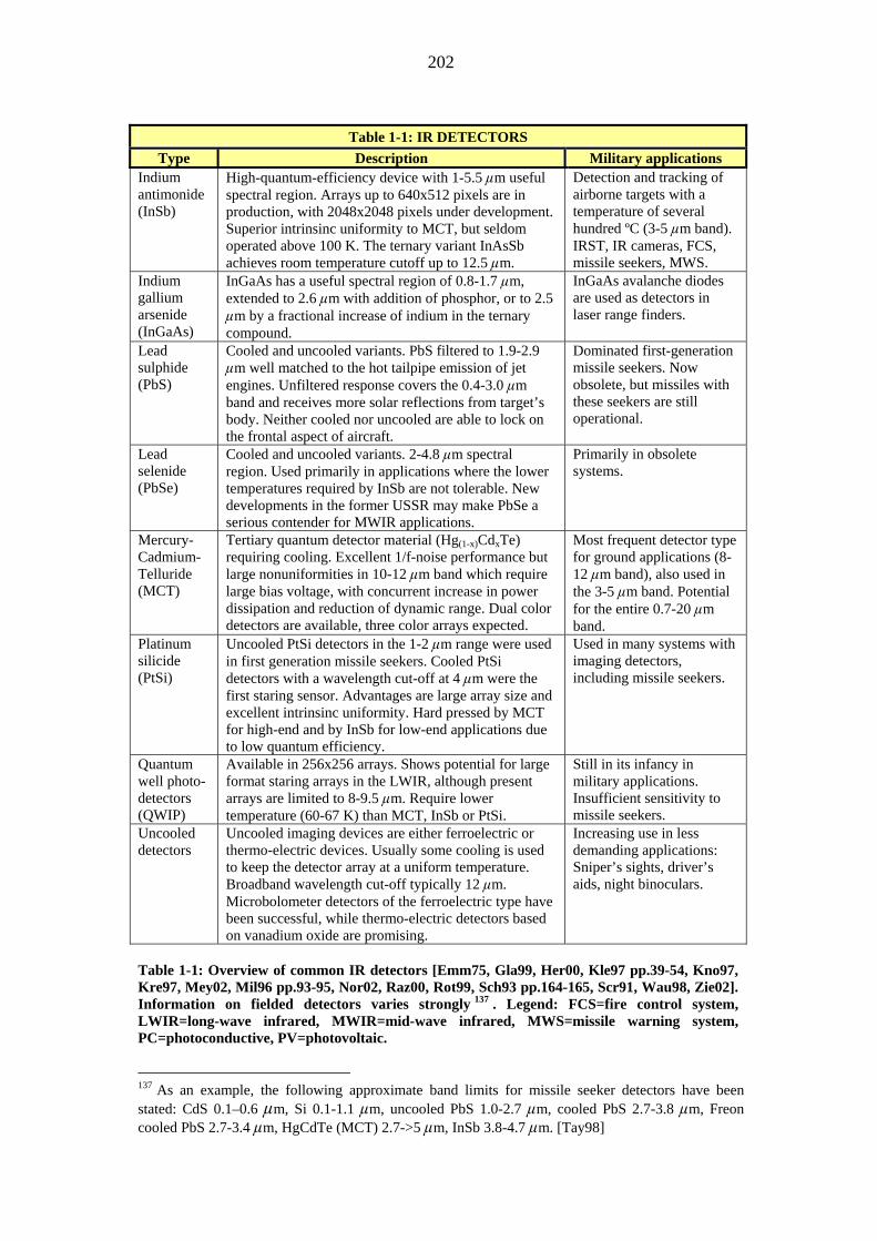
202
Table 1-1: IR DETECTORS
Type Description Military applications Indium antimonide (InSb)
High-quantum-efficiency device with 1-5.5 m useful spectral region. Arrays up to 640x512 pixels are in production, with 2048x2048 pixels under development. Superior intrinsinc uniformity to MCT, but seldom operated above 100 K. The ternary variant InAsSb achieves room temperature cutoff up to 12.5 m.
Detection and tracking of airborne targets with a temperature of several hundred ºC (3-5 m band). IRST, IR cameras, FCS, missile seekers, MWS.
Indium gallium arsenide (InGaAs)
InGaAs has a useful spectral region of 0.8-1.7 m, extended to 2.6 m with addition of phosphor, or to 2.5
m by a fractional increase of indium in the ternary compound.
InGaAs avalanche diodes are used as detectors in laser range finders.
Lead sulphide (PbS)
Cooled and uncooled variants. PbS filtered to 1.9-2.9 m well matched to the hot tailpipe emission of jet
engines. Unfiltered response covers the 0.4-3.0 m band and receives more solar reflections from target’s body. Neither cooled nor uncooled are able to lock on the frontal aspect of aircraft.
Dominated first-generation missile seekers. Now obsolete, but missiles with these seekers are still operational.
Lead selenide (PbSe)
Cooled and uncooled variants. 2-4.8 m spectral region. Used primarily in applications where the lower temperatures required by InSb are not tolerable. New developments in the former USSR may make PbSe a serious contender for MWIR applications.
Primarily in obsolete systems.
Mercury-Cadmium-Telluride (MCT)
Tertiary quantum detector material (Hg(1-x)CdxTe) requiring cooling. Excellent 1/f-noise performance but large nonuniformities in 10-12 m band which require large bias voltage, with concurrent increase in power dissipation and reduction of dynamic range. Dual color detectors are available, three color arrays expected.
Most frequent detector type for ground applications (8-12 m band), also used in the 3-5 m band. Potential for the entire 0.7-20 m band.
Platinum silicide (PtSi)
Uncooled PtSi detectors in the 1-2 m range were used in first generation missile seekers. Cooled PtSi detectors with a wavelength cut-off at 4 m were the first staring sensor. Advantages are large array size and excellent intrinsinc uniformity. Hard pressed by MCT for high-end and by InSb for low-end applications due to low quantum efficiency.
Used in many systems with imaging detectors, including missile seekers.
Quantum well photo-detectors (QWIP)
Available in 256x256 arrays. Shows potential for large format staring arrays in the LWIR, although present arrays are limited to 8-9.5 m. Require lower temperature (60-67 K) than MCT, InSb or PtSi.
Still in its infancy in military applications. Insufficient sensitivity to missile seekers.
Uncooled detectors
Uncooled imaging devices are either ferroelectric or thermo-electric devices. Usually some cooling is used to keep the detector array at a uniform temperature. Broadband wavelength cut-off typically 12 m. Microbolometer detectors of the ferroelectric type have been successful, while thermo-electric detectors based on vanadium oxide are promising.
Increasing use in less demanding applications: Sniper’s sights, driver’s aids, night binoculars.
Table 1-1: Overview of common IR detectors [Emm75, Gla99, Her00, Kle97 pp.39-54, Kno97, Kre97, Mey02, Mil96 pp.93-95, Nor02, Raz00, Rot99, Sch93 pp.164-165, Scr91, Wau98, Zie02]. Information on fielded detectors varies strongly 137 . Legend: FCS=fire control system, LWIR=long-wave infrared, MWIR=mid-wave infrared, MWS=missile warning system, PC=photoconductive, PV=photovoltaic.
137 As an example, the following approximate band limits for missile seeker detectors have been stated: CdS 0.1–0.6 m, Si 0.1-1.1 m, uncooled PbS 1.0-2.7 m, cooled PbS 2.7-3.8 m, Freon cooled PbS 2.7-3.4 m, HgCdTe (MCT) 2.7->5 m, InSb 3.8-4.7 m. [Tay98]

203
Table 1-2a: NON-SCANNING RF RECEIVERS Type Properties
The most basic RWR solution, still very popular. Strengths - High POI (virtually 100%).
- Wide RF bandwidth; can cover the entire band of interest. - Rapid detection output. - Capability to detect short pulses. - Capable of measuring amplitudes in the LVA version. - Low cost.
CVR
Weaknesses - Low sensitivity (é-50 dBm), but increases with wideband LNA in front of the detector. - No frequency measurement capability. - AC coupled video amplifier requires that CW signals are chopped to allow detection. - Noise on CW signals may fire the leading edge detector. - Can be blinded by strong simultaneous signals; in particular the response time of an LVA is a problem.
Most common receiver type for frequency measurements. Either analog or digital (DIFM) architecture. Strengths - Instantaneous frequency measurements.
- Excellent frequency resolution, responds well to frequency agility. - Multi-GHz RF bandwidth. - Submicrosecond delay. - Capability to detect short pulses. - Compact. - Reasonable cost. - Detects intra- and inter-pulse frequency agile emitters (DIFM).
IFM
Weaknesses - Reports an erroneous frequency based on the vector sum of multiple signals present, e.g. multiple CW signals. (Proposals for measuring two simultaneous signals exist [Tsu94].) Serious errors occur, however, only at less than 3 dB power separation between signals. - Wideband sensitivity limited to approx. -60 dBm. - Poor against modulated CW in a crowded environment.
Essentially a bank of CVRs separated by bandpass filters. Strengths - Resolves/processes multiple RF input over a wide spectrum.
- Frequency measurement with accuracy depending on channel widths. - Wide instantaneous BW. - High POI. - Capability to detect short pulses.
Channelized
Weaknesses - “Rabbit ear” transients at channel overlap. - Limitations in dynamic range on signals in nearby frequencies. - Resolution limited by number of channels. - Large size. - High cost (depends on number of channels).
Table 1-2a: Characteristics of common non-scanning EW receivers [Bro98 pp.194-203, Sch86 pp.59-69, Sel92, Sul02, Tsu86, Vac93 pp.97-151, Wie91 pp.139-159, Wil98 pp.12-18]. Receiver block diagrams are presented in Table 1-2d. Note that resolution and accuracy of measurement are not identical; accuracy is mostly much lower than resolution and can never be better than it [Tsu86 p.83]. Low-noise architecture has less dynamic range than a receiver with a mixer front-end [Sko80 p.550]. Receiver sensitivity is a controversial issue since the general tendency is to ask for high sensitivity. However, the determining factor on operational sensitivity is the acceptable probability of false alarm [Vac93 p.87]. Higher sensitivity also tends to lead to lower dynamic range [Tsu95 p.13]. Legend: AC=alternate current, BW=bandwidth, CVR=crystal video receiver, DIFM=digital IFM, IFM= instantaneous frequency measurement, LNA=low-noise amplifier, LVA=logarithmic video amplifier, POI=probability of intercept.

204
Table 1-2b: SCANNING RF RECEIVERS
Type Properties Most common radar receiver; allows amplification at IF. Strengths - High sensitivity (>-90 dBm with 4 MHz BW over the 0.5 to 18 GHz
band) and excellent frequency selectivity. - CW signal acquisition time is not a problem for narrow-IBW receiver. - Nearly matched to unmodulated pulse radars if IF BW is about reciprocal of pulse width. - Good against pulse Doppler and pulse compression radars if IF BW is matched to pulse compression code BW. - Faster than YIG-tuned receivers.
Tuned, super-heterodyne
Weaknesses - Narrow instantaneous bandwidth (4 MHz), leading to low POI for pulsed signals. Wideband tuned receivers are possible if mixed e.g. with an IFM receiver for frequency measurement. - Restricted against chirped signals: Limited range, PW cannot be measured, multiple frequencies reported. - Poor linearity. - Spurious responses of the mixer. - Risk for polarity errors in signal tail causing servo to lock on wrong null point. - Preservation of sensitivity requires scan rate limit of approx. (BW)2 of the IF.
Common auxiliary RWR receiver; implemented as CVR or LVA receiver preceded by a YIG-tuned filter. Strengths - CW signal acquisition time is not a problem for narrow-IBW
receiver. - Multioctave RF tuning. - Excellent linearity.
Tuned, YIG
Weaknesses - Restricted against chirped signals: Limited range, PW cannot be measured, multiple frequencies reported. - Low POI. - Slow tuning due to magnetic material. - Hysteresis that needs to be eliminated if knowledge of absolute frequency is required.
Uncommon despite obvious advantages. Also called microscan receiver. Strengths - High POI.
- Fast scan rate. - Moderately high bandwidth. - High sensitivity. - Provides frequency information. - Processes simultaneous signals assuming that they fill the DDL. - Interference from CW signals usually not a problem.
Compressive
Weaknesses - Fairly complex digitizing circuitry. - Digitizing of compressed video pulses that may be as short as 1 ns. - Pulses that do not fill the DDL can degrade performance. - Pulses shorter than the scan period may be missed. - IBW limitations determined by DDL capability. - Some limitations on dynamic range due to filter triple travel.
Table 1-2b: Characteristics of common scanning EW receivers [Bro98 pp.197-202, Sch86 pp.59-69; Sel92; Sul02; Tsu86; Vac93 pp. 97-126,153-168; Wie91 pp.159-164,180-183; Wil98 pp.11-18; Wis85]. Receiver block diagrams are presented in Table 1-2d. Compressive (microscan) receivers are not known to be used in helicopter EWSP suites. Proposed optical IFM and scanning receivers [Cho95, Win99, Win02] have yet to materialize. Legend: BW=bandwidth, DDL=dispersive delay line, IBW=instantaneous bandwidth, IF=intermediate frequency, YIG=yttrium iron garnet.

205
Table 1-2c: OTHER RF RECEIVERS
Type Properties Standard and interferometric Bragg cell solutions. Strengths - Multiple simultaneous RF inputs.
- Wide instantaneous BW (2 GHz). - Good frequency resolution (5 MHz) depending on the number of photodetectors at the output. - Small size. - Low/moderate cost.
Acousto-optic
Weaknesses - Low sensitivity. - Low dynamic range (30 dB) although cascading brings improvements.
Latest development stage in receiver technology. Strengths - The stability, repeatability, and flexibility/programmability of digital
technology. - Allows signal processing that otherwise is not possible, e.g. wideband instantaneous analysis through FFT processing. - Inherent radar ECCM capability through enough IBW that allows real-time spectrum analysis around the target frequency. - Simple to extend to a DRFM that produces coherent time delays. - Indefinite storage time of intercepted signals. - Cost can become low as technology advances. - Improved processing of data streams for detection of LPI signals.
Digital
Weaknesses -Insufficient BW to directly digitize input signals, requires a superhet pre-receiver. Hence needs support by a wide band receiver in EW applications. -Time delay of single-AD approach.
Table 1-2c: Characteristics of acousto-optic and digital EW receivers [Bro98 pp.203-205; Kai96; Kla99; Ner01 pp.109-110,322-323,500; Pac00 pp.19-57; Sch86 pp.59-69; Sel92; Sul02; Vac93 pp.183-206; Wie91 pp.176-180]. Receiver block diagrams are presented in Table 1-2d. Acousto-optic receivers are not known to be used in helicopter EWSP suites; Brooks and Reeve [Bro95] mentions much better frequency resolution than in the table, and Self [Sel92] regards the sensitivity of AO receivers as good. Digital receivers for RWRs are still in the development stage; unclassified information on the software-implemented architecture has not been published. Pace [Pac00 p.56] suggests a definition of absolute sensitivity for digital receivers as the lowest input power at the IF that reliably produces a PDW. Vaccaro [Vac93 p.198] states that misalignment and jitter in timing occur in two-AD digital receiver solutions, whereas Neri [Ner01 p.110] claims “very good I/Q channels balancing”. Legend: AD=analog-to-digital, DRFM=digital radio-frequency memory, FFT=fast Fourier transform, I-Q=in-quadrature, PDW=pulse descriptor word. Note on receivers in Tables 1-2a,b,c: The POI is high only within the instantaneous bandwidth (IBW) of the receiver. Receivers with narrow IBW therefore have low POI for the entire bandwidth of interest. To improve the POI for important threat systems the IBW scan pattern of narrow-band receivers is usually controlled by the mission data file (MDF).

206
Table 1-2d: RF RECEIVER BLOCK DIAGRAMS
CVR
Antenna
Detector
Videoamplifier
Comparator
Thresholdvoltage
+
-
RF filter
LNA
IFM
Antenna
Powerdivider
Limitingamplifier
Phasedetector
Delay line
Processor
sin
cosFrequency
information
Super-heterodyne
Antenna
Detector Videoamplifier
Thresholdvoltage
LO
IFamplifier
Mixer
IF filter
Comparator
+
-
Channelized
Antenna
LO
Mixer
IF filter
Detector Videoamplifier
LO
IFamplifier
Mixer
IF filter
Continues/…

207
Table 1-2d: RF RECEIVER BLOCK DIAGRAMS Compressive
Antenna IFamplifier
MixerWeighting
filter
SweepingLO
DDL Videodetector
FMchirp
Acousto-optic
Braggcell
Lasersource
Antenna
RF down-conversion
IF in
DetectorarrayIF
amplifier
Frequencyinformation
Laserbeam
2
sin = 2
Symbols: = Bragg angle, = wavelength of light, = wavelength of acoustic energy
Digital
Antenna
RF down-conversion
ADconversion
IF Spectrumanalyzer
Analoguedata
Digitaldata
Parameterencoder
PDW Digitalprocessor
I
Q
Table 1-2d: Block diagrams for receivers mentioned in Tables 1-2. A preamplifier and RF filter have been shown only for the CVR, a threshold stage only for the CVR and superhet receivers. Adapted from [Bro98, Gol87 p.159, Ner01 p.319, Sch86, Pac00, Tsu86, Vac93]. For a proposed channelized digital IFM receiver, see [Tsu96]. Commonly used acousto-optic materials are tellurium dioxide, lead molybdate, and gallium phospide [Bro95]. The digital receiver is implemented either with one or two AD converters; the single-AD solution requires twice the sampling rate to achieve the same IBW as the double-AD solution [Ner01 pp.319-320]. The block diagram for channelized receivers represents the traditional approach; for new designs only digital receiver solutions are considered. Legend: AD=analogue-to-digital, DDL=dispersive delay line, FM=frequency modulation, IBW=instantaneous bandwidth, IF=intermediate frequency, LNA=low-noise amplifier, LO=local oscillator, PDW=pulse descriptor word, RF=radio-frequency.
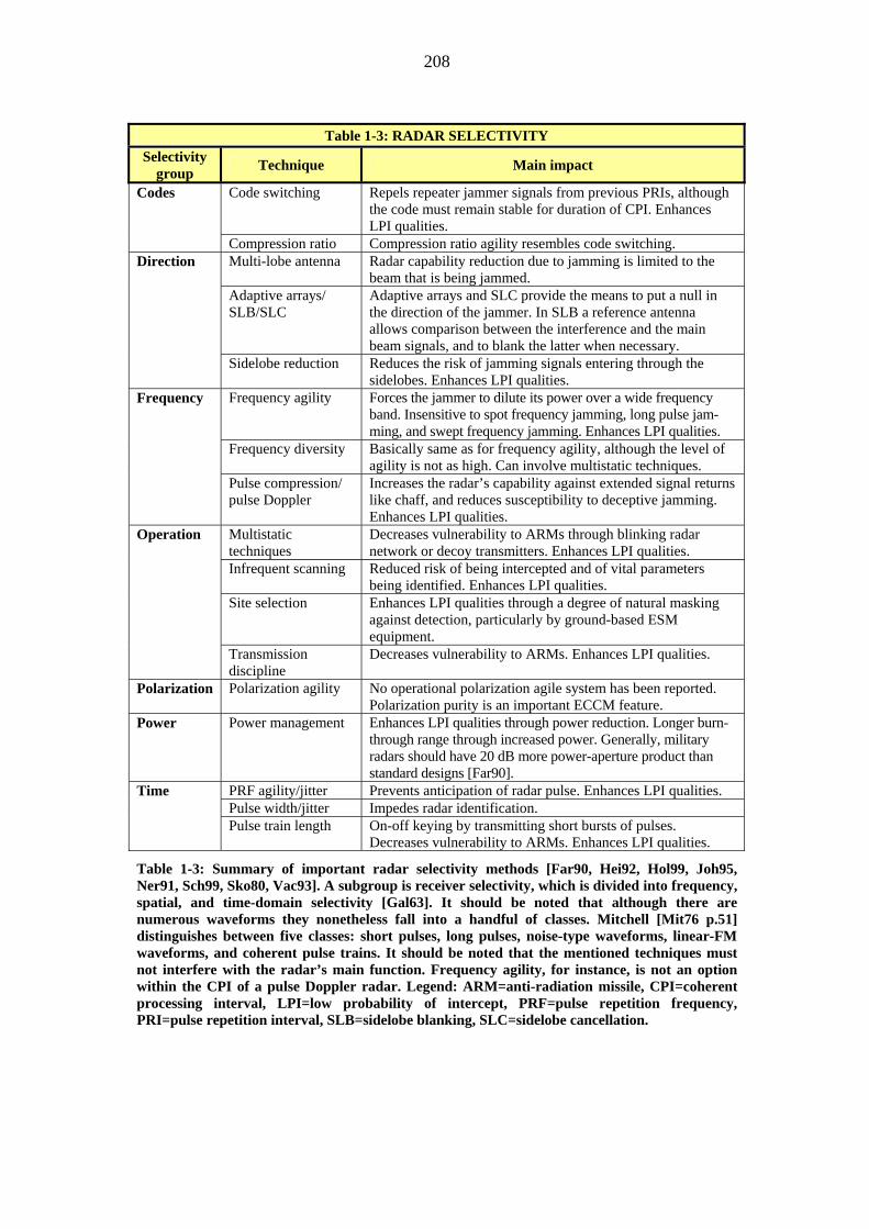
208
Table 1-3: RADAR SELECTIVITY
Selectivity group Technique Main impact
Code switching Repels repeater jammer signals from previous PRIs, although the code must remain stable for duration of CPI. Enhances LPI qualities.
Codes
Compression ratio Compression ratio agility resembles code switching. Multi-lobe antenna Radar capability reduction due to jamming is limited to the
beam that is being jammed. Adaptive arrays/ SLB/SLC
Adaptive arrays and SLC provide the means to put a null in the direction of the jammer. In SLB a reference antenna allows comparison between the interference and the main beam signals, and to blank the latter when necessary.
Direction
Sidelobe reduction Reduces the risk of jamming signals entering through the sidelobes. Enhances LPI qualities.
Frequency agility Forces the jammer to dilute its power over a wide frequency band. Insensitive to spot frequency jamming, long pulse jam-ming, and swept frequency jamming. Enhances LPI qualities.
Frequency diversity Basically same as for frequency agility, although the level of agility is not as high. Can involve multistatic techniques.
Frequency
Pulse compression/ pulse Doppler
Increases the radar’s capability against extended signal returns like chaff, and reduces susceptibility to deceptive jamming. Enhances LPI qualities.
Multistatic techniques
Decreases vulnerability to ARMs through blinking radar network or decoy transmitters. Enhances LPI qualities.
Infrequent scanning Reduced risk of being intercepted and of vital parameters being identified. Enhances LPI qualities.
Site selection Enhances LPI qualities through a degree of natural masking against detection, particularly by ground-based ESM equipment.
Operation
Transmission discipline
Decreases vulnerability to ARMs. Enhances LPI qualities.
Polarization Polarization agility No operational polarization agile system has been reported. Polarization purity is an important ECCM feature.
Power Power management Enhances LPI qualities through power reduction. Longer burn-through range through increased power. Generally, military radars should have 20 dB more power-aperture product than standard designs [Far90].
PRF agility/jitter Prevents anticipation of radar pulse. Enhances LPI qualities. Pulse width/jitter Impedes radar identification.
Time
Pulse train length On-off keying by transmitting short bursts of pulses. Decreases vulnerability to ARMs. Enhances LPI qualities.
Table 1-3: Summary of important radar selectivity methods [Far90, Hei92, Hol99, Joh95, Ner91, Sch99, Sko80, Vac93]. A subgroup is receiver selectivity, which is divided into frequency, spatial, and time-domain selectivity [Gal63]. It should be noted that although there are numerous waveforms they nonetheless fall into a handful of classes. Mitchell [Mit76 p.51] distinguishes between five classes: short pulses, long pulses, noise-type waveforms, linear-FM waveforms, and coherent pulse trains. It should be noted that the mentioned techniques must not interfere with the radar’s main function. Frequency agility, for instance, is not an option within the CPI of a pulse Doppler radar. Legend: ARM=anti-radiation missile, CPI=coherent processing interval, LPI=low probability of intercept, PRF=pulse repetition frequency, PRI=pulse repetition interval, SLB=sidelobe blanking, SLC=sidelobe cancellation.

209
Table 1-4: VERIFICATION AND VALIDATION TOOLS
Tool Advantages Disadvantages M&S + Supports establishment of mission-level requirements
and translation of these into system specifications. + Can assist studies of alternative concepts that satisfy operational needs. + Can support OAR pretest planning and complement OAR tests by extending known parameters and test data to other operational scenarios. + Can address MOE issues that cannot be determined directly from OAR tests.
- Can be expensive to develop, operate, maintain, and validate. - Suffers from lack of confidence if not validated.
Uni
nsta
lled
suite
+ Gives the opportunity to evaluate EWSP systems before installation on the platform. + Tests can be performed when the platform is not ready for the EWSP suite, or when the interface HW and SW are not ready for integrated tests.
- Does not provide information on the influence of the platform and its avionics. - Does not support evaluation of the coupling of free-space radiation.
Inst
alle
d su
ite
+ Allows evaluation of the integrated avionic system’s responses to stimulation. + Allows a limited test setup with antenna hats placed over the apertures of a parked aircraft. + Virtually any hostile or friendly RF emission can be generated . + Flying in an operational scenario can be simulated with computer controlled tools. + Saves time and money by identifying system performance problems. + Provides preflight and postflight checkout of the aircraft’s avionics. + Can be used to identify EMI and EMC problems between onboard avionics. + The human operator can be included e.g. by linking an anechoic chamber to a flight simulator.
- Free-space radiation in an anechoic chamber problematic due to limited space. - Anechoic chamber does not allow all aircraft systems to be switched on. - Target dynamics must be factored into the evaluation and polarization; concessions must be made.
Ground test on EWSP suite
Feat
ures
com
mon
to a
ll gr
ound
test
s
+ Provide methods to test EWSP performance in representative/multispectral threat environments + Provide preflight and complementing data to OAR tests. + Can overcome shortage of OAR threat simu-lators by providing a dense signal environment to evaluate system performance. + Can provide an environment that represents an integrated air defense system. + Indoor facilities provide a secure test environ-ment for classified systems.
- A complete picture of system performance cannot be ascertained. - Test simulator needs validation to ensure credible results. - The human factor is mainly not taken into account in ground test facilities. - No realistic simulation of expendable ejection and threat responses. - Do not simulate very well such environ-mental factors as terrain, meteorological, or atmospheric conditions.
OAR flight test
+ Provides the most credible data for T&E and shows how the system will perform in the operational environment, allows examination of many effects that cannot be accounted for with digital M&S and ground tests. + Provides data to calibrate digital models and to validate threat simulators in ground test facilites. + Provides complete end-to-end evaluation from sensor to aircrew members display in a dynamic environment, MMI issues can be addressed.
- Range restrictions, instrumentation, safety considerations can restrict the tests; restricted battlefield densities and diversities. - Replication of tests is difficult, achieving statistical significance is costly. - OARs cannot keep up with the development of the latest threat systems. - The OAR is seldom truly representative of the operational environment.
Table 1-4: Advantages and disadvantages of some V&V tools. Ground tests are divided into two groups, tests on uninstalled and installed EWSP suites. The emphasis is on RF systems, since test methods for these are more developed than for EO systems. [Anon95, Wri93] Legend: EMC=electromagnetic compatibility, EMI=electromagnetic interference, MOE=measure of effectiveness, MMI=man-machine interface, OAR=open air range.

210
Appendix 1, References Ald02 Alder, C.: Air Target Seekers: Next Generation and Beyond, Techniques and
technologies, Proceedings of the SMi Global Missile Summit 2002, SMi Conferences Ltd., London, 7-8 October 2002
Anon95 Anonymous: Electronic Warfare Test and Evaluation Process—Direction and Methodology for EW Testing, AF Manual 99-112, US Air Force, 27 March, 1995
Bal03 Ball, R.E.: The Fundamentals of Aircraft Combat Survivability Analysis and Design, 2nd edition, AIAA Education Series, 2003
Bel98 Bell, W.A., Glasgow, B.B.: On the Next Generation of Imaging Infrared Seekers for Anti-aircraft Missiles, Proc. SPIE, Vol. 3377, 1998, pp. 220-230
Bro95 Brooks, P., Reeve, C.D.: Limitations in acousto-optic FM demodulators, IEE Proceedings on Optoelectronics, Vol. 142, No. 3, June 1995, pp. 149-156
Bro98 Browne, J.P.R., Thurbon, M.T.: Electronic Warfare, Brassey’s, 1998 Car63 Carpenter, R.O’B.: Comparison of AM and FM Reticle Systems, Applied Optics, Vol. 2,
No. 3, pp. 229-236. Reprinted in Olsson, G. (ed.): Selected Papers on Reticles and their Applications, SPIE Milestone Series, Vol. MS155, 1999, pp. 350-357
Cho95 Choi, Y.M.: Recent Advances in Electro-Optical Devices, Components and System for Microwave and Millimetre-Wave Applications, International Journal of Infrared and Millimeter Waves, Vol. 16, No. 8, 1995, pp. 1261-1284
Coo99 Cook, N.: The disappearing helicopter, Jane’s Defence Weekly, 28 July 1999, pp. 23-26 Cou02 Courts, M.: RAH-66 Comanche, Presentation at the Military Helicopter Conference,
London, England, 23 April 2002 (CD ROM) Cra80 Craubner, S.: Digital simulation of reticle-systems, Image Processing for Missile
Guidance, SPIE, Vol. 238, 1980, pp. 414-424 Dir93 Dirschler, R.: Plume Radiation, AGARD Lecture Series 188, AGARD-LS-188, June
1993, pp. 6/1-6/47, Accessible through <http://www.rta.nato.int/Abstracts.asp> (Accessed 12.3.2004)
Dri91 Driggers, R.G.: et al.: Parameters of spinning AM reticles, Applied Optics, Vol. 30, No. 19, 1 July 1991, pp. 2675-2684
Emm75 Emmons, R.B. et al.: Infrared Detectors: An Overview, Optical Engineering, Vol. 14(1), pp. 21-30, 1975. Reprinted in: Johnson, R.B. et al. (eds.): Selected Papers on Infrared Design, SPIE Vol. 513, Part One, 1985, pp. 601-610
Far90 Farina, A.: Electronic Counter-Countermeasures, Ch. 9 in: Skolnik, M.I. (ed.): Radar Handbook, 2nd ed., McGraw-Hill, Inc., 1990
Fra00 Frawley, R.C. et al.: Suppression System for a Gas Turbine Engine, US Patent No. 6,134,879, October 24, 2000
Gal63 Galenian, J.C.: Designing Radar Receivers to Overcome Jamming, Electronics Magazine, Vol. 36, May 17, 1963, pp. 50-54. Reprinted as chapter 6.2 in Johnston, S.L. (ed.): Radar Electronic Counter-Countermeasures, Artech House, Inc., 1980
Ger85 Gerson, G.: Tracking Systems, Ch. 22 in Wolfe, W.L., Zissis, G.J. (eds.): The Infrared Handbook, rev. ed., Environmental Research Center of Michigan, 1985. Pages 22/38-22/46 are reprinted in Olsson, G. (ed.): Selected Papers on Reticles and their Applications, SPIE Milestone Series, Vol. MS155, 1999, pp. 122-130
Gla99 Glasgow, B., Bell, W: The Future of Anti-Aircraft Imaging Infrared Seeker Missile Threats, Proceedings of the 1999 IEEE Aerospace Conference, Vol. 4, 6-13 March 1999, pp. 457-465
Gol87 Golden, A. Jr.: Radar Electronic Warfare, AIAA Education Series, 1987 Gro03 Grossman, J. et al.: Vertical Envelopment and the Future Transport Rotorcraft:
Operational Considerations for the Objective Force, RAND Study MR-1713-A, 2003, <http://www.rand.org/publications/MR/MR1713> (Retrieved 25.7.2004)
Hei92 Heikkilä, E.: Elektronisen Sodankäynnin Vaikutukset Tutkan Rakenteeseen (The Influence of EW on Radar Design), Seminar handout, State Technical Research Center VTT, February 1992 (partially in Finnish)
Her00 Herskovitz, D.: You Bet Your Life: Today’s Missile Warning Systems, The Journal of Electronic Defense, April 2000, pp. 51-56

211
Hoi95 Hoisington, D.B.: Electronic Warfare, Lynx Publishing, Sunnyvale, CA, 1995 (Two volumes)
Hol99 Holbourn, P.E.: The Future Evolution of Airborne Radar, Military Technology, 8/1999, pp. 57-64
How88 Hovanessian, S.A.: Introduction to Sensor Systems, Artech House, Inc., 1988 Hud69 Hudson, R.D. jr: Infrared System Engineering, John Wiley & Sons, Inc., 1969. Pages
235-263 are reprinted in Olsson, G. (ed.): Selected Papers on Reticles and their Applications, SPIE Milestone Series, Vol. MS155, 1999, pp. 43-71
Jah97 Jahng, S.G. et al.: Design and analysis of improved instantaneous field of view of rosette scanning infrared seeker, IEE Electronics Letters, Vol. 33, No. 23, 6th November 1997, pp.1964-1965
Joh95 Johnston, S.L.: CESM—A New Category of Radar ECCM, IEEE Trans AES, Vol. 31, No. 2, April 1995, pp. 854-856
Kai96 Kaiser, S.G.: Digital Receiver Technology, Architecture, and Application, Digest of the 1996 IEEE Microwave Symposium, Vol. 3, IEEE MTT-S International, 17-21 June 1996, pp. 1331-1334
Kla99 Klass, P.J.: RWR, ESM Changes Prompt Litton Merger, Aviation Week & Space Technology, November 15, 1999, pp. 89-90
Kle97 Klein, L.A.: Millimeter-Wave and Infrared Multisensor Design and Signal Processing, Artech House, Inc., 1997
Kno97 Knowles, P., Baker, I.M.: Mercury cadmium telluride staring arrays for mid-IR detection, IEE Proc.-Optron., Vol. 144, No. 5, October 1997, pp.327-330
Kre97 Kreider, J. et al.: Uncooled infrared arrays sense image scenes, Laser Focus World, August 1997, p. 197
May83 May, J.J. Jr, Van Zee, M.E.: Electro-Optic and Infrared Sensors, Microwave Journal, September 1983, p. 121
Mey02 Meyer, B.: The Incredible Shrinking IR Camera, Photonics Spectra, April 2002, pp. 119-124
Mil96 Miller, J.L., Friedman, E.: Photonics Rules of Thumb, McGraw-Hill, 1996 Mis97 Misiurewicz, J., et al.: Analysis of Recorded Helicopter Echo, Proceedings of the IEE 97
Radar Conference, 14-16 October 1997, pp. 449-453 (IEE Publication No. 449) Mit76 Mitchell, R.L.: Radar Signal Simulation, Artech House, Inc., 1976 Ner91 Neri, F.: Introduction to Electronic Defense Systems, Artech House, Inc., 1991 Ner01 Neri, F.: Introduction to Electronic Defense Systems, 2nd edition, Artech House, Inc.,
2001 Nor02 Norton, P.: HgCdTe infrared detectors, Opto-Electronics Review, Vol. 10, No. 3, 2002,
pp. 159-174, <http://www.wat.edu.pl/review/optor/10(3)159.pdf> (Retrieved 10.8.2004) Oh01 Oh, J.S. et al.: A New Two-color Cancellation Algorithm for Counter-counter-measures
of Infrared Seekers, Optical Engineering, August 2001, <http://candy.ee.cau.ac.kr/ paper/intl_pasper/IJ-8.pdf> (Retrieved 21.5.2002)
Ols92 Olsson, G.: Simulering Retikelmålsökning—Metodbeskrivning (Simulation of Reticle Seekers—Description of Method), FOA Rapport, C 30685-8.3, November 1992 (in Swedish)
Ols94 Olsson, G.: Simulation of reticle seekers by means of an image processing system, Optical Engineering, Vol. 33, No. 3, pp. 730-736. Reprinted in Olsson, G. (ed.): Selected Papers on Reticles and their Applications, SPIE Milestone Series, Vol. MS155, 1999, pp. 461-467
Pac00 Pace, P.E.: Advanced Techniques for Digital Receivers, Artech House, Inc., 2000 Por91 Porras, M.A. et al.: Amplitude-modulated and frequency-modulated reticle responses of
Gaussian beams, Optical Engineering, Vol. 30, No. 12, pp. 1986-1992. Reprinted in Olsson, G. (ed.): Selected Papers on Reticles and their Applications, SPIE Milestone Series, Vol. MS155, 1999, pp. 424-430
Raz00 Razeghi, M.: Optoelectronic Devices Based on III-V Compound Semiconductors Which Have Made Major Scientific and Technological Impact in the Past 20 Years, IEEE Journal on Selected Topics in Quantum Electronics, Vol. 6, No. 6, November/December 2000, p. 1344
Ree81 Reedy, E.K., Ewell, G.W.: Millimeter Radar, Ch. 2 in Button, K.J., Wiltse, J.C. (eds.): Infrared and Millimeter Waves, Volume 4, Millimeter Systems, Academic Press, 1981
Rot99 Rotolante, R.A.: Why the IR detector market is in a flux, Laser Focus World, October 1999, p. 65

212
Sch86 Schleher, D.C.: Introduction to Electronic Warfare, Artech House, Inc., 1986 Sch93 Schmieder, D.E., Walker, G.W.: Camouflage, Suppression, and Screening Systems, Ch.
2 Accetta, J.S., Shumaker, D.L. (eds.): The Infrared and Electro-Optical Systems Handbook, Vol. 7 (Countermeasure Systems), Environmental Research Institute of Michigan, SPIE Optical Engineering Press, 1993
Sch99 Schleher, D.C.: Electronic Warfare in the Information Age, Artech House, Inc., 1999 Scr91 Scribner, D.A. et al.: Infrared Focal Plane Array Technology, Proceedings of the IEEE,
Vol. 79, No. 1, January 1991, pp. 66-85 Sel92 Self, A.G.: LOW COST ESM—what technology opportunities? Proceedings of the 1992
International Radar Conference (Radar 92), 12-13 October 1992, pp.175-179 Sko80 Skolnik, M.I.: Introduction to Radar Systems, 2nd ed., McGraw-Hill Book Company,
1980 Sul02 Sullivan, W.B.: Instantaneous Frequency Measurement Receivers for Maritime Patrol,
The Journal of Electronic Defense, Vol. 25, No. 10, 2002, p. 55 Tay98 Taylor, B.: Advanced Electro-optical/Infrared Countermeasures, Handout from briefing
at the 35th AOC Symposium, Virginia Beach, VA, October 1998 Tsu86 Tsui, J.B.-Y.: Microwave Receivers With Electronic Warfare Applications, John Wiley
& Sons, Inc., 1986 Tsu94 Tsui, J., Hedge, J.N.: Instantaneous Frequency Measurement (IFM) Receiver With Two
Signal Capability, US Patent No. 5,291,125, March 1, 1994 Tsu96 Tsui, J.B.Y.: Digital Channelized IFM Receiver, US Patent No. 5,499,391, March 12,
1996 Tsu95 Tsui, J.: Digital Techniques for Wideband Receivers, Artech House, Inc. 1995 Vac93 Vaccaro, D.D.: Electronic Warfare Receiving Systems, Artech House, Inc., 1993 Wau98 Wauters, J.: Novel IR detectors operate at room temperature, Laser Focus World, May
1998, p. 175 Wie91 Wiegand, J.R.: Radar Electronic Countermeasures Systems Design, Artech House, Inc.,
1991 Wil93 Wilmot, D.W. et al: Warning systems, Ch. 1 in Accetta, J.S., Shumaker, D.L. (eds.): The
Infrared and Electro-Optical Systems Handbook, Vol. 7 (Countermeasure Systems), Environmental Research Institute of Michigan, SPIE Optical Engineering Press, 1993
Wil98 Wiley, R.G.: Intercepting Modern Signals, Seminar handout, 35th annual AOC International Convention, Virginia Beach, VA, 30 October 1998
Win99 Winnall, S.T., Lindsay, A.C.: A Fabry-Perot Scanning Receiver for Microwave Signal Processing, IEEE Transactions on Microwave Theory and Techniques, Vol. 47, No. 7, July 1999, pp. 1385-1390
Win02 Winnall, S.T., Hunter, D.B.: A Fibre Bragg Grating Based Scanning Receiver for Electronic Warfare Applications, (IEEE) International Topical Meeting on Microwave Photonics (MWP ’01), 7-9 January 2002, pp. 211-214
Wis85 Wiseman, C.: Fine Resolution Angle of Arrival Is the Key to Sorting Agile Threats, International Countermeasures Handbook 1985, 10th Edition, EW Communications, Inc., 1985, pp. 324-329
Wri93 Wright, F.L.: Operational Test and Evaluation of Electronic Combat Systems, Air University Press, AU-ARI-92-2, August 1993
Zel93 Zeller, B.M. (chair): Terminology and Assessment Methods of Solid Rocket Propellant Exhaust Signatures, AGARD-AR-287, February 1993, Accessible through <http://www. rta.nato.int/Abstracts.asp > (Retrieved 24.2.2004)
Zie02 Ziegler, J. et al.: Advanced sensor technologies for high performance infrared detectors, Infrared Physics & Technology, Vol. 43, 2002, pp. 239-243

213
APPENDIX 2: PARAMETERS IN FSD MODELS Parameters used in the FSD model in Figure 8.
Parameter Value Motivation COLLECTION DELAY
12 Month Assumed time for collecting information on a new subject.
CONVERSION EFFICIENCY
0.33 Pieces Every third piece of knowledge is assumed to contribute to gaining new information.
INITIAL INFORMATION
100 Pieces Selected as a basic value.
INITIAL KNOWLEDGE
1000 Pieces Selected as a basic value.
LEARNING DELAY 24 Month Assumed delay in transforming information into knowledge.
LEARNING EFFICIENCY
0.1 1/Month The collected and stored information are assumed to convert into knowledge by 10%/month.
RATE OF OBSOLESCENCE
0.02 1/Month The collected and stored information are assumed to become obsolescent (be forgotten) by 2 %/Month before being turned into knowledge.
Table 2-1: Motivation for parameter selection for the FSD example in Figure 8. The parameters are purely fictive, since the model serves only as a didactic example on FSD modeling and simulation.

214
Parameters used in the Capability Model (Figure 63)
Parameter Value Motivation CM IMPORTANCE TO THREAT DEVELOPMENT
0.166667 Dmnl
Assumed ratio for CM influence on threat development. Cannot be too high if available development resources are tied to work based on general technological progress.
EWSp influence on budget changes
1 Hypothetical value (c (0.5, 2), approximately), used only to study the influence of sudden changes.
EWSP OBSOLESCENCE
1% per annum The rate has to be conservative since old threats (radar modes etc.) can reemerge in new systems.
EXPECTED EWSP EFFECTIVENESS
0.8 The value 0.8 is required by the US DHS for DIRCM effectiveness on commercial airliners.
INITIAL EVADABLE
2000 Lethality Initial number of threats (INITIAL EVADABLE + INITIAL IDENTIFIED + INITIAL UNIDENTIFIED = 3000) is below the capacity of British Sky Guardian 2000 RWR (4000 data file entries).
INITIAL EWSP FUNDING
0.5 Million Euro/Month
Annual EWSP costs of € 6 Million (the cost for 30-40 man-years of labor) for maintaining 2000 CM modes and developing 120 new ones.
INITIAL IDENTIFIED
500 Mode(s) Threats for which CMs do not exist are assumed to split 50-50 between identified and unidentified at time zero.
INITIAL PRODUCTIVITY
12.5 Lethality/ Month
Basic value for the simulation; the number of threats doubles in 20 years with a constant 12.5 Lethality/Month.
INITIAL UNIDENTIFIED
500 Mode(s) Threats for which CMs do not exist are assumed to split 50-50 between identified and unidentified at time zero.
INTELLIGENCE DELAY
24 Month(s) Assumed that 60% knowledge on unidentified threats can be gained in 24 months.
INTELLIGENCE EFFICIENCY
0.6 Dmnl Assumed that 60% knowledge on unidentified threats can be gained in 24 months.
REALLOCATION DELAY
24 Month(s) One year for preparing budget allocation plus one year for the budget cycle. Shorter if existing funds are “cannibalized”.
THREAT DEVELOPMENT DELAY
24 Month(s) Assumed average time for developing threats. Selected quite short since the delay is mainly seen being related to crash programs in response to developed CMs.
THREAT INCENTIVE
10 Lethality/ Month
The growth of threats that the EWSP suite has to identify and counter is a mixture of radar modes, missile seekers and laser pulses. Doubling in 25 years is adequate.
TIME TO BUILD CAPABILITY
36 Month(s) Three years is typical for hiring and training new personnel, constructing and equipping new facilities, etc.
TIME TO DEVELOP CM
24 Month(s) The time required to develop CMs varies widely; from hours in the case of new radar modes (war modes) to years in case a new EWSP system has to be developed.
Table 2-2: Motivation for parameter selection for the Capability Model. Legend: DHS=Department of Homeland Security, Dmnl= dimensionless.

215
Parameters used in the Campaign Model (Figure 68)
Parameter Value Motivation AVERAGE TIME ACTIVE
9 Hours Enemy air defense assets are assumed to shift positions twice a day, with three hours required for redeployment and nine hours remaining for target engagement.
ENEMY BDR DURATION
48 Hours The value can change from minutes, in the case of computer rebooting, to days or more in case of damages caused by hard-kill assets. 48 hours is selected as a compromise.
ENEMY COMBAT EFFECTIVENESS
0.0001 Dmnl/Hour*Asset
Equals to a combat outcome of 1 hit friendly asset per 10,000 hours for each enemy asset. The figure is realistic in a combat scenario that lasts for a month without completely exhausting resources.
ENEMY P-KILL GIVEN A HIT
0.3 Dmnl The discussion has shown Pk/H values to vary greatly in different scenarios, 30% is a realistic figure.
EWSP CM POTENTIAL
0.9 Dmnl Percentage of approaching threats countered by the EWSP suite. The US DHS has required at least 80% CM effectiveness of DIRCMs on civil aircraft. Since MDF restrictions lower the true EWSP capability the intrinsic potential must exceed the expected capability.
EWSP INTEL CONTRIBUTION
0.5 Dmnl The parameter value (c [0, 1]) adds to INTELLIGENCE EFFECTIVENESS. The value 0.5 is a baseline value that can be altered in order to study the potential intelligence contribution of EWSP and its effects on survivability.
FRIENDLY BDR DURATION
48 Hours The discussion has shown that 48 hours is often used as a benchmark for helicopter BDR. The value can be altered in order to investigate its effects.
FRIENDLY COMBAT POTENTIAL
0.0001 Dmnl/Hour*Asset
Equals to a combat outcome of 1 hit enemy asset per 10,000 hours for each friendly asset. See above ENEMY COMBAT EFFECTIVENESS.
FRIENDLY P-KILL GIVEN A HIT
0.3 Dmnl The discussion has shown Pk/H values to vary greatly in different scenarios, 30% is a realistic figure. See ENEMY P-KILL GIVEN A HIT.
HIGH-TECH THREAT RATIO
0.2 Dmnl The value depends on the combat scenario. A high-/low-tech ratio of 20% is realistic for helicopters in a mixed combat scenario, but is low if stand-off assets are considered. The value can be altered in order to study effects on the outcome.
INITIAL ACTIVE ASSETS
80 Asset The enemy’s total initial assets are 100, a number selected for the ease in expressing changes in percent. 80% are active and 20 % are inactive.
INITIAL FRIENDLY ASSETS
120 Asset The value 120 is selected only to differ slightly from enemy assets at the start of the conflict (100 Assets).
INITIAL PASSIVE ASSETS
20 Asset 20% of the enemy’s assets are initially inactive. See INITIAL ACTIVE ASSETS.
INTELLIGENCE EFFECTIVENESS
0.6 Dmnl Assumes that 60% of the required intelligence can be gathered by strategic assets within the time determined by AVERAGE TIME ACTIVE. That is, the time during which enemy assets remain at a specific location before redeploying.
Continues/…

216
Parameter Value Motivation MAXIMUM ACTIVITY
0.4444 Dmnl/Hour
The value is selected to give a constant ratio (80%/20%) between “Engaging enemy assets” and “Passive enemy assets” (unless the loop is disturbed by external factors) assuming AVERAGE TIME ACTIVE = 9 hours and “campaign intensity”=1 (Dmnl).
SUPPRESSION SCALE POINT
0.008 Dmnl/Hour Decay point at which the enemy’s reaction to friendly capability is considered to be at equilibrium. The numeric value given through INITIAL FRIENDLY ASSETS = 80 (Asset) times FRIENDLY COMBAT POTENTIAL = 0.0001 (Dmnl/Hour*Asset), equals to 0.008 (Dmnl/Hour).
Table 2-3: Motivation for parameter selection for the Campaign Model.

217
Parameters used in the Mission Model (Figure 74)
Parameter Value Motivation ESCORT RESOURCE LIMIT
0.00556 seconds
The effectiveness of escort assets drops if threats emerge more often than one every third minute. Time is needed to find a firing position, detect and identify the threat, fire upon it, and to catch up with the other helicopters.
ESCORT TIME TO SUPPRESS HALF
60 seconds Time required by escort assets to detect and identify the threat, align to the threat, fire, and for penetrator fly-out.
EWSP GRACE PERIOD
5 seconds Time available for EWSP to counter incoming threats.
EWSP TIME TO COUNTER POINT EIGHT
3 seconds The EWSP suite can detect, identify, and counter 80% of the approaching threats on the average in 3 seconds. 80% success rate is the requirement by the US DHS.
FLIGHT LEG DURATION
900 seconds Support assets attack threats in the 15-minute flight route window that precedes the arrival of helicopters.
FLIGHT TACTICS LIMIT
0.01667 Lethality/ second
The helicopter is able to successfully utilize flight route selection if the threats emerge no more often than one per minute. More densely located threats saturate flight tactics.
PEAK NUMBER OF THREATS
0.05 Lethality/ second
Conversion factor that multiplied with the normalized “Threat distribution” lookup table gives the sought number of threats (0.05x900x4.4=198).
PENETRATOR MISS TIME
2 seconds Time remaining for missile to hit or miss once EWSP GRACE PERIOD has passed. The total penetrator fly-out time is assumed to be 5+2=7 seconds.
POP-UP ELIMINATION TIME
90 seconds Pop-up threats should be eliminated within 1.5 minutes by escort assets, or they will fire on the helicopter(s).
POP-UP FLYBY TIME
90 seconds Pop-up threats endanger the helicopter if they are in a ±45 second window (flight range) around the helicopters.
STANDOFF TIME TO HALF THREAT
1200 seconds Half of the threats can be eliminated if attacks preceding the arrival of helicopters last for 20 minutes.
TIME TO HALF THREATS BY TACTICS
90 seconds Half of the threats are assumed to be bypassed at a penalty of 1.5 minutes flight time (helicopters in NOE flight).
THREAT TIME TO HIT HALF
3 seconds Time required by the threat to hit half of its targets.
Table 2-4: Motivation for parameter selection for the Mission Model.