electronics and communication engineering subject: arm and
TRANSCRIPT

BMS INSTITUTE OF TECHNOLOGY AND MANAGEMENT
Avalahalli, Doddaballapura Main Road, Bangalore – 560064
Electronics and Communication Engineering
Subject: ARM and Embedded System
Code: 17EC62
Table of Contents
Sl.No Modules Page.No
1 1 1-13
2 2 14-38
3 3 39-78
4 4 79-92
5 5 93-126


EMBEDDED SYSTEM COMPONENTS MODULE-3
.DEFINITION OF AN EMBEDDED SY STEM
An embedded system is a combination of 3 types of components: a. Hardware b. Software c.
Mechanical Components and it is supposed to do one specific task only.
Example 1: Washing Machine
A washing machine from an embedded systems point of view has: a. Hardware: Buttons, Display
& buzzer, electronic circuitry. b. Software: It has a chip on the circuit that holds the software which
drives controls & monitors the various operations possible. c. Mechanical Components: the
internals of a washing machine which actually wash the clothes control the input and output of
water, the chassis itself.
Example 2: Air Conditioner
An Air Conditioner from an embedded systems point of view has: a. Hardware: Remote, Display
& buzzer, Infrared Sensors, electronic circuitry. b. Software: It has a chip on the circuit that holds
the software which drives controls & monitors the various operations possible. The software
monitors the external temperature through the sensors and then releases the coolant or suppresses
it. c. Mechanical Components: the internals of an air conditioner the motor, the chassis, the outlet,
etc An embedded system is designed to do a specific job only.
Example: a washing machine can only wash clothes, an air conditioner can control the
temperature in the room in which it is placed.
The hardware & mechanical components will consist all the physically visible things that are used
for input, output, etc. An embedded system will always have a chip (either microprocessor or
microcontroller) that has the code or software which drives the system
EMBEDDED SYSTEM & GENERAL PURPOSE COMPUTER
The Embedded System and the General purpose computer are at two extremes. The embedded
system is designed to perform a specific task whereas as per definition the general purpose
computer is meant for general use. It can be used for playing games, watching movies, creating
software, work on documents or spreadsheets etc. Following are certain specific points that
differenciates between embedded systems and general purpose computers:

EMBEDDED SYSTEM COMPONENTS MODULE-3
CLASSIFICATION OF EMBEDDED SYSTEMS
The classification of embedded system is based on following criteria's:
On generation
On complexity & performance
On deterministic behavior
On triggering
On generation:
1. First generation (1G):
Built around 8bit microprocessor & microcontroller.
Simple in hardware circuit & firmware developed.
Examples: Digital telephone keypads.
2. Second generation (2G):
Built around 16-bit µp & 8-bit µc.
They are more complex & powerful than 1G µp & µc.

EMBEDDED SYSTEM COMPONENTS MODULE-3
Examples: SCADA systems
3. Third generation (3G):
Built around 32-bit µp& 16-bit µc.
Concepts like Digital Signal Processors (DSPs), Application Specific Integrated
Circuits(ASICs) evolved. Examples: Robotics, Media, etc.
4. Fourth generation:
Built around 64-bit µp & 32-bit µc.
The concept of System on Chips (SoC), Multicore Processors evolved.
Highly complex & very powerful. Examples: Smart Phones.
On complexity & performance:
1. Small-scale:
Simple in application need
Performance not time-critical.
Built around low performance& low cost 8 or 16 bit µp/µc. Example: an electronic toy
2. Medium-scale:
Slightly complex in hardware & firmware requirement.
Built around medium performance & low cost 16 or 32 bit µp/µc.
Usually contain operating system.
Examples: Industrial machines.
3. Large-scale:
Highly complex hardware & firmware.
Built around 32 or 64 bit RISC µp/µc or PLDs or Multicore-Processors.
Response is time-critical.
Examples: Mission critical applications.
On deterministic behavior:
This classification is applicable for “Real Time” systems.
The task execution behavior for an embedded system may be deterministic or non-
deterministic.
Based on execution behavior Real Time embedded systems are divided into Hard and
Soft.

EMBEDDED SYSTEM COMPONENTS MODULE-3
On triggering
Embedded systems which are “Reactive” in nature canbe based on triggering.
Reactive systems can be:
Event triggered
Time triggered
APPLICATION OF EMBEDDED SYSTEM
The application areas and the products in the embedded domain are countless.
1. Consumer Electronics: Camcorders, Cameras.
2. Household appliances: Washing machine, Refrigerator.
3. Automotive industry: Anti-lock breaking system(ABS), engine control.
4. Home automation & security systems: Air conditioners, sprinklers, fire alarms.
5. Telecom: Cellular phones, telephone switches.
6. Computer peripherals: Printers, scanners.
7. Computer networking systems: Network routers and switches.
8. Healthcare: EEG, ECG machines.
9. Banking & Retail: Automatic teller machines, point of sales.
10. Card Readers: Barcode, smart card readers.
PURPOSE OF EMBEDDED SYSTEM
1. Data Collection/Storage/Representation
Embedded system designed for the purpose of data collection performs acquisition
of data from the external world.
Data collection is usually done for storage, analysis, manipulation and
transmission.
Data can be analog or digital.
Embedded systems with analog data capturing techniques collect data directly in
the form of analog signal whereas embedded systems with digital data collection

EMBEDDED SYSTEM COMPONENTS MODULE-3
mechanism converts the analog signal to the digital signal using analog to digital
converters.
If the data is digital it can be directly captured by digital embedded system.
A digital camera is a typical example of an embedded System with data
collection/storage/representation of data.
Images are captured and the captured image may be stored within the memory of
the camera. The captured image can also be presented to the user through a graphic
LCD unit.
2. Data communication
Embedded data communication systems are deployed inapplications from complex
satellite communication to simple home networking systems.
The transmission of data is achieved either by a wire-lin medium or by a wire-less
medium. Data can either be transmitted by analog means or by digital means.
Wireless modules-Bluetooth, Wi-Fi.
Wire-line modules-USB, TCP/IP.
Network hubs, routers, switches are examples of dedicated data transmission
embedded systems.
3. Data signal processing
Embedded systems with signal processing functionalities are employed in
applications demanding signal processing like speech coding, audio video codec,
transmission applications etc.
A digital hearing aid is a typical example of an embedded system employing data
processing. Digital hearing aid improves the hearing capacity of hearing impaired
person.
4. Monitoring
All embedded products coming under the medical domain are with monitoring
functions. Electro cardiogram machine is intended to do the monitoring of the
heartbeat of a patient but it cannot impose control over the heartbeat.
Other examples with monitoring function are digital CRO, digital multi-meters, and
logic analyzers.
5. Control
A system with control functionality contains both sensors and actuators Sensors are
connected to the input port for capturing the changes in environmental variable and
the actuators connected to the output port are controlled according to the changes
in the input variable.
Air conditioner system used to control the room temperature to a specified limit is
a typical example for CONTROL purpose.

EMBEDDED SYSTEM COMPONENTS MODULE-3
6. Application specific user interface
Buttons, switches, keypad, lights, bells, display units etc are application specific
user interfaces.
Mobile phone is an example of application specific user interface.
In mobile phone the user interface is provided through the keypad, system speaker,
vibration alert etc.
CORE OF EMBEDDED SYSTEMS
Embedded systems are domain and application specific and are built around a central core. The
core of the embedded system falls into any of the following categories:
1. General purpose and Domain Specific Processors Microprocessors Microcontrollers Digital
Signal Processors.
2. Application Specific Integrated Circuits. (ASIC)
3. Programmable logic devices(PLD’s)
4. Commercial off-the-shelf components (COTs)
GENERAL PURPOSE AND DOMAIN SPECIFIC PROCESSOR.
• Almost 80% of the embedded systems are processor/ controller based.
• The processor may be microprocessor or a microcontroller or digital signal processor, depending
on the domain and application.
Microprocessors
A microprocessor is a silicon chip representing a central processing unit.
A microprocessor is a dependent unit and it requires the combination of other hardware
like memory, timer unit, and interrupts controller, etc. for proper functioning.
Developers of microprocessors.
Intel – Intel 4004 – November 1971(4-bit).
Intel – Intel 4040. o Intel – Intel 8008 – April 1972.
Intel – Intel 8080 – April 1974(8-bit).
Motorola – Motorola 6800.
Intel – Intel 8085 – 1976.
Zilog - Z80 – July 1976.

EMBEDDED SYSTEM COMPONENTS MODULE-3
Architectures used for processor design are Harvard or VonNeumann.

EMBEDDED SYSTEM COMPONENTS MODULE-3
Microcontrollers
A microcontroller is a highly integrated chip that contains aCPU, scratch pad RAM, special
and general purpose register arrays,on chip ROM/FLASH memory for program storage ,
timer and interrupt control units and dedicated I/O ports.
Texas Instrument’s TMS 1000 Is considered as the world’s first microcontroller.
Some embedded system application require only 8 bit controllers whereas some requiring
superior performance and computational needs demand 16/32 bit controllers.
The instruction set of a microcontroller can be RISC or CISC.
Microcontrollers are designed for either general purpose application requirement or
domain specific application requirement.
Digital Signal Processors
DSP are powerful special purpose 8/16/32 bit microprocessor designed to meet the
computational demands and power constraints of today’s embedded audio, video and
communication applications. DSP are 2 to 3 times faster than general purpose
microprocessors in signal processing applications.
This is because of the architectural difference between DSP and general purpose
microprocessors.
DSPs implement algorithms in hardware which speeds up the execution whereas general
purpose processor implement the algorithm in software and the speed of execution depends
primarily on the clock for the processors.
DSP includes following key units:
i. Program memory: It is a memory for storing the program required by DSP to process
the data. ii. Data memory: It is a working memory for storing temporary variables and
data/signal to be processed.
iii. Computational engine: It performs the signal processing in accordance with the stored
program memory computational engine incorporated many specialized arithmetic units and
each of them operates simultaneously to increase the execution speed. It also includes
multiple hardware shifters for shifting operands and saves execution time.
iv. I/O unit: It acts as an interface between the outside world and DSP. It is responsible for
capturing signals to be processed and delivering the processed signals.
Examples: Audio video signal processing, telecommunication and multimedia
applications. SOP(Sum of Products) calculation, convolution, FFT(Fast Fourier
Transform), DFT(Discrete Fourier Transform), etc are some of the operation performed by
DSP.

EMBEDDED SYSTEM COMPONENTS MODULE-3
Application Specific Integrated Circuits. (ASIC)
ASICs is a microchip design to perform a specific and unique applications.
Because of using single chip for integrates several functions there by reduces the system
development cost.
Most of the ASICs are proprietary (which having some trade name) products, it is referred
as Application Specific Standard Products(ASSP).
As a single chip ASIC consumes a very small area in the total system.
Thereby helps in the design of smaller system with high capabilities or functionalities.
The developers of such chips may not be interested in revealing the internal detail of it .
Programmable logic devices(PLD’s)
A PLD is an electronic component. It used to build digital circuits which are reconfigurable.
A logic gate has a fixed function but a PLD does not have a defined function at the time of
manufacture.
PLDs offer customers a wide range of logic capacity, features, speed, voltage
characteristics. PLDs can be reconfigured to perform any number of functions at any time.
A variety of tools are available for the designers of PLDswhich are inexpensive and help
to develop, simulate and test the designs.
PLDs having following two major types.
1) CPLD(Complex Programmable Logic Device): CPLDs offer much smaller amount of
logic up to 1000 gates.
2) FPGAs(Field Programmable Gate Arrays): It offers highest amount of performance as
well as highest logic density, the most features.
Advantages of PLDs :- 1) PLDs offer customer much more flexibility during the design
cycle.
2) PLDs do not require long lead times for prototypes or production parts because PLDs
are already on a distributors shelf and ready for shipment.
3) PLDs can be reprogrammed even after a piece of equipment is shipped to a customer
Commercial off-the-shelf components(COTs)
1) A Commercial off the Shelf product is one which is used 'asis'.
2) The COTS components itself may be develop around a general purpose or domain
specific processor or an ASICs or a PLDs.
3) The major advantage of using COTS is that they are readily available in the market, are
chip and a developer can cut down his/her development time to a great extent

EMBEDDED SYSTEM COMPONENTS MODULE-3
4) The major drawback of using COTS components in embedded design is that the
manufacturer of the COTS component may withdraw the product or discontinue the
production of the COTS at any time if rapid change in technology occurs.
Advantages of COTS:
1) Ready to use
2) Easy to integrate
3) Reduces development time
Disadvantages of COTS:
1) No operational or manufacturing standard (all proprietary)
2) Vendor or manufacturer may discontinue production of a particular COTS product
SENSORS & ACTUATORS
Sensor
A Sensor is used for taking Input
It is a transducer that converts energy from one form to another for any measurement or
control purpose Ex. A Temperature sensor
Actuator
Actuator is used for output. It is a transducer that may be either mechanical or electrical which
converts signals to corresponding physical actions.
LED (Light Emitting Diode)
LED is a p-n junction diode and contains a CATHODE and ANODE For functioning the anode
is connected to +ve end of power supply and cathode is connected to –ve end of power supply.
The maximum current flowing through the LED is limited by connecting a RESISTOR in series
between the power supply and LED as shown in the figure below
There are two ways to interface an LED to a microprocessor/microcontroller:

EMBEDDED SYSTEM COMPONENTS MODULE-3
1. The Anode of LED is connected to the port pin and cathode to Ground : In this approach the
port pin sources the current to the LED when it is at logic high(ie. 1).
2. The Cathode of LED is connected to the port pin and Anode to Vcc : In this approach the port
pin sources the current to the LED when it is at logic high (ie. 1). Here the port pin sinks the current
and the LED is turned ON when the port pin is at Logic low (ie. 0)
7-segment display:
A seven-segment display (SSD), or seven-segment indicator, is a form of electronic display
device for displaying decimal numerals that is an alternative to the more complex dot matrix
displays.Seven-segment displays are widely used in digital clocks, electronic meters, basic
calculators, and other electronic devices that display numerical information.
The seven elements of the display can be lit in different combinations to represent the Arabic
numerals. Often the seven segments are arranged in an oblique (slanted) arrangement, which aids
readability. In most applications, the seven segments are of nearly uniform shape and size (usually
elongated hexagons, though trapezoids and rectangles can also be used), though in the case of
adding machines, the vertical segments are longer and more oddly shaped at the ends in an effort to
further enhance readability.
The numerals 6 and 9 may be represented by two different glyphs on seven-segment displays, with
or without a 'tail'.[2][3] The numeral 7 also has two versions, with or without segment F.[4]
The seven segments are arranged as a rectangle of two vertical segments on each side with one
horizontal segment on the top, middle, and bottom. Additionally, the seventh segment bisects the
rectangle horizontally. There are also fourteen-segment displays and sixteen-segment displays
(for full alphanumerics); however, these have mostly been replaced by dot matrix

EMBEDDED SYSTEM COMPONENTS MODULE-3
displays. Twenty-two segment displays capable of displaying the full ASCII character set[5] were
briefly available in the early 1980s, but did not prove popular.
The segments of a 7-segment display are referred to by the letters A to G, where the optional
decimal point (an "eighth segment", referred to as DP) is used for the display of non- integer
numbers.
Optical coupler:
An optical coupler, also called opto-isolator, optocoupler, opto coupler, photocoupler or optical
isolator, is a passive optical component that can combine or split transmission data (optical power)
from optical fibers. It is an electronic device which is designed to transfer electrical signals by
using light waves in order to provide coupling with electrical isolation between its input and output.
The main purpose of an optocoupler is to prevent rapidly changing voltages or high voltages on
one side of a circuit from distorting transmissions or damaging components on the other side of
the circuit. An optocoupler contains a light source often near an LED which converts electrical
input signal into light, a closed optical channel and a photosensor, which detects incoming light
and either modulates electric current flowing from an external power supply or generates electric
energy directly. The sensor can either be a photoresistor, a silicon-controlled rectifier, a
photodiode, a phototransistor or a triac.

EMBEDDED SYSTEM COMPONENTS MODULE-3
Applications for Optocouplers:
Photoresistor-based opto-isolators are the slowest type of optocouplers, but also the most linear
isolators and are used in the audio and music industry. Most opto-isolators available use bipolar
silicon phototransistor sensors and reach medium data transfer speed, which is enough for
applications like electroencephalography. High speed opto-isolators are used in computing and
communications applications. Other industrial applications include photocopiers, industrial
automation, professional light measurement instruments and auto-exposure meters.
Relay :
A relay is an electrically operated switch. Many relays use an electromagnet to mechanically
operate a switch, but other operating principles are also used, such as solid-state relays. Relays are
used where it is necessary to control a circuit by a separate low-power signal, or where several
circuits must be controlled by one signal. The first relays were used in long distance
telegraphcircuits as amplifiers: they repeated the signal coming in from one circuit and re-
transmitted it on another circuit. Relays were used extensively in telephone exchanges and early
computers to perform logical operations. A type of relay that can handle the high power required
EMBEDDED SYSTEM COMPONENTS MODULE-3
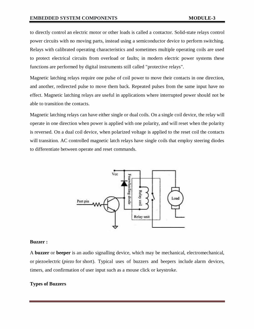
to directly control an electric motor or other loads is called a contactor. Solid-state relays control
power circuits with no moving parts, instead using a semiconductor device to perform switching.
Relays with calibrated operating characteristics and sometimes multiple operating coils are used
to protect electrical circuits from overload or faults; in modern electric power systems these
functions are performed by digital instruments still called "protective relays".
Magnetic latching relays require one pulse of coil power to move their contacts in one direction,
and another, redirected pulse to move them back. Repeated pulses from the same input have no
effect. Magnetic latching relays are useful in applications where interrupted power should not be
able to transition the contacts.
Magnetic latching relays can have either single or dual coils. On a single coil device, the relay will
operate in one direction when power is applied with one polarity, and will reset when the polarity
is reversed. On a dual coil device, when polarized voltage is applied to the reset coil the contacts
will transition. AC controlled magnetic latch relays have single coils that employ steering diodes
to differentiate between operate and reset commands.
Buzzer :
A buzzer or beeper is an audio signalling device, which may be mechanical, electromechanical,
or piezoelectric (piezo for short). Typical uses of buzzers and beepers include alarm devices,
timers, and confirmation of user input such as a mouse click or keystroke.
Types of Buzzers

EMBEDDED SYSTEM COMPONENTS MODULE-3
There are several different kinds of buzzers. At Future Electronics we stock many of the most
common types categorized by Type, Sound Level, Frequency, Rated Voltage, Dimension and
Packaging Type. The parametric filters on our website can help refine your search results
depending on the required specifications.
The most common sizes for Sound Level are 80 dB, 85 dB, 90 dB and 95 dB. We also carry buzzers
with Sound Level up to 105 dB. There are several types available including Electro-Acoustic,
Electromagnetic, Electromechanic, Magnetic and Piezo, among others.
Applications for Buzzers:
Typical uses of buzzers include:
Alarm devices
Timers
Confirmation of user input (ex: mouse click or keystroke)
Electronic metronomes
Annunciator panels
Game shows
Sporting events
Household appliances
Push button switch:
A push-button (also spelled pushbutton) or simply button is a simple switch mechanism for
controlling some aspect of a machine or a process. Buttons are typically made out of hard material,
usually plastic or metal.[1] The surface is usually flat or shaped to accommodate the human finger
or hand, so as to be easily depressed or pushed. Buttons are most often biased switches, although
many un-biased buttons (due to their physical nature) still require a spring to return to their un-
pushed state. Terms for the "pushing" of a button include pressing, depressing, mashing, hitting,
and punching. The "push-button" has been utilized in calculators, push-button telephones, kitchen
appliances, and various other mechanical and electronic devices, home and commercial.

EMBEDDED SYSTEM COMPONENTS MODULE-3
In industrial and commercial applications, push buttons can be connected together by a mechanical
linkage so that the act of pushing one button causes the other button to be released. In this way, a
stop button can "force" a start button to be released. This method of linkage is used in simple
manual operations in which the machine or process has no electrical circuits for control.
Red pushbuttons can also have large heads (called mushroom heads) for easy operation and to
facilitate the stopping of a machine. These pushbuttons are called emergency stop buttons and for
increased safety are mandated by the electrical code in many jurisdictions. This large mushroom
shape can also be found in buttons for use with operators who need to wear glovesfor their work
and could not actuate a regular flush-mounted push button.
Communication Interface (onboard and external types):
For any embedded system, the communication interfaces can broadly classified into:
1. Onboard Communication Interfaces :These are used for internal communication of the
embedded system i.e: communication between different components present on the system.
Common examples of onboard interfaces are:
Inter Integrated Circuit (I2C)
Serial Peripheral Interface (SPI)
Universal Asynchronous Receiver Transmitter (UART)
1-Wire Interface
Parallel Interface
Inter Integrated Circuit (I2C)
I2C was originally developed in 1982 by Philips for various Philips chips. The original spec
allowed for only 100kHz communications, and provided only for 7-bit addresses, limiting the
number of devices on the bus to 112 (there are several reserved addresses, which will never be
used for valid I2C addresses). In 1992, the first public specification was published, adding a
400kHz fast-mode as well as an expanded 10-bit address space. Much of the time (for instance, in
the ATMega328 device on many Arduino-compatible boards) , device support for I2C ends at this

EMBEDDED SYSTEM COMPONENTS MODULE-3
point. There are three additional modes specified: fast-mode plus, at 1MHz; high-speed mode, at
3.4MHz; and ultra-fast mode, at 5MHz.
Each I2C bus consists of two signals: SCL and SDA. SCL is the clock signal, and SDA is the data
signal. The clock signal is always generated by the current bus master; some slave devices may
force the clock low at times to delay the master sending more data (or to require more time to
prepare data before the master attempts to clock it out). This is called “clock stretching” and is
described on the protocol page.
Unlike UART or SPI connections, the I2C bus drivers are “open drain”, meaning that they can
pull the corresponding signal line low, but cannot drive it high. Thus, there can be no bus
contention where one device is trying to drive the line high while another tries to pull it low,
eliminating the potential for damage to the drivers or excessive power dissipation in the
system.Each signal line has a pull-up resistor on it, to restore the signal to high when no device is
asserting it low.
Serial Data Line (SDA)
The Serial Data Line (SDA) is the data line (of course!). All the data transfer among the devices
takes place through this line.
Serial Clock Line (SCL)
The Serial Clock Line (SCL) is the serial clock (obviously!). I2C is a synchronous protocol, and
hence, SCL is used to synchronize all the devices and the data transfer together. We’ll learn how
it works a little later in this post.

EMBEDDED SYSTEM COMPONENTS MODULE-3
SPI BUS :
Serial Peripheral Interface, or SPI, is a very common communication protocol used for two-way
communication between two devices. A standard SPI bus consists of 4 signals,
Master Out Slave In (MOSI), Master In Slave Out (MISO), the clock (SCK), and Slave
Select (SS). Unlike an asynchronous serial interface, SPI is not symmetric. An SPI bus has one
master and one or more slaves. The master can talk to any slave on the bus, but each slave can only
talk to the master. Each slave on the bus must have it's own unique slave select signal. The master
uses the slave select signals to select which slave it will be talking to. Since SPI also includes a
clock signal, both devices don't need to agree on a data rate beforehand. The only requirement is
that the clock is lower than the maximum frequency for all devices involved.
Each SPI transfer is full-duplex, meaning that data is sent from the master to the slave and from
the slave to the master at the same time. There is no way for a slave to opt-out of sending data
when the master makes a transfer, however, devices will send dummy bytes (usually all 1's or all
0's) when communication should be one way. If the master is reading data in for a slave, the slave
will know to ignore the data being sent by the master.
Devices that use SPI typically will send/receive multiple bytes each time the SS signal goes low.
This way the SS signal acts as a way to frame a transmission. For example, if you had a flash
memory that had an SPI bus and you want to read some data, the SS signal would go low, the

EMBEDDED SYSTEM COMPONENTS MODULE-3
Advantages of SPI:
It’s faster than asynchronous serial
The receive hardware can be a simple shift register
It supports multiple slaves
Disadvantages of SPI:
It requires more signal lines (wires) than other communications methods
The communications must be well-defined in advance (you can’t send random amounts
of data whenever you want)
The master must control all communications (slaves can’t talk directly to each other)
It usually requires separate SS lines to each slave, which can be problematic if numerous
slaves are needed.
UART
In UART communication, two UARTs communicate directly with each other. The transmitting
UART converts parallel data from a controlling device like a CPU into serial form, transmits it in
serial to the receiving UART, which then converts the serial data back into parallel data for the
receiving device. Only two wires are needed to transmit data between two UARTs. Data flows
from the Tx pin of the transmitting UART to the Rx pin of the receiving UART:
master would send the command to read memory at a certain address, and as long as the master
kept SS low and toggling SCK the flash memory would keep sending out data. Once SS returned
high the flash memory knows to end the read command.
Since the MISO signal can be connected to multiple devices, each device will only drive the line
when its SS signal is low. This is shown by the grey area.

EMBEDDED SYSTEM COMPONENTS MODULE-3
UARTs transmit data asynchronously, which means there is no clock signal to synchronize the
output of bits from the transmitting UART to the sampling of bits by the receiving UART. Instead
of a clock signal, the transmitting UART adds start and stop bits to the data packet being
transferred. These bits define the beginning and end of the data packet so the receiving UART
knows when to start reading the bits.
When the receiving UART detects a start bit, it starts to read the incoming bits at a specific
frequency known as the baud rate. Baud rate is a measure of the speed of data transfer, expressed
in bits per second (bps). Both UARTs must operate at about the same baud rate. The baud rate
between the transmitting and receiving UARTs can only differ by about 10% before the timing of
bits gets too far off.
1-wire interface:
A 1994 application note explained that the only serial-port interface options for 1-Wire devices
were microcontroller port pins, UARTs, and UART-based COM ports. Since that time special
driver chips have been developed for direct connection to a UART, I²C bus, or USB port.
Meanwhile, the number of 1-Wire devices also grew to a long list.These various developments
made it necessary to update the earlier documentation. Instead of merging the specifics of all
relevant information into a single document, this new document refers the reader to other
application notes whenever possible.
The first 1-Wire devices, the DS199x series, were produced in SRAM technology. Next the
nonvolatile EPROM technology became available, and the DS198x and DS250x series devices
were released. These EPROM devices need a 12V programming pulse and are not erasable. The
next leap forward was EEPROM technology, which allows programming and erasing at 5V or

EMBEDDED SYSTEM COMPONENTS MODULE-3
less. EEPROM technology is found in DS197x, DS243x and DS28Exx series devices. To ensure
proper power, EEPROM devices may need a master that supports "strong pullup", a feature that
temporarily bypasses the 1-Wire pullup resistor with a low-impedance path. The extra power is
needed for write cycles and, in case of the DS1977, also for reading. Besides EEPROM devices,
the strong pullup also powers 1-Wire temperature sensors and special functions such as a SHA-1
engine, which is found in secure 1-Wire devices. Temperature logger iButtons® use SRAM
technology and, therefore, do not have any special, external power requirements.
General Information:
1- Wire is the only voltage-based digital system that works with two contacts, data and ground, for
half-duplex bidirectional communication. A 1-Wire system consists of a single 1-Wire master and
one or more 1-Wire slaves. The 1-Wire concept relies both on a master that initiates digital
communication, and on self-timed 1-Wire slave devices that synchronize to the master's signal.
The timing logic of master and slave must measure and generate digital pulses of various widths.
When idle, a high-impedance path between the 1-Wire bus and the operating voltage puts the 1-
Wire bus in the logic-high state. Each device on the bus must be able to pull the 1-Wire bus low at
the appropriate time by using an open-drain output (wired AND). If a transaction needs to be
suspended for any reason, the bus must be left in the idle state so the transaction can resume.
Parallel port:

EMBEDDED SYSTEM COMPONENTS MODULE-3
A parallel port is a type of interface found on computers (personal and otherwise) for connecting
peripherals. The name refers to the way the data is sent; parallel ports send multiple bits of data at
once, in parallel communication, as opposed to serial interfaces that send bits one at a time. To do
this, parallel ports require multiple data lines in their cables and port connectors, and tend to be
larger than contemporary serial ports which only require one data line.
There are many types of parallel ports, but the term has become most closely associated with the
printer port or Centronics port found on most personal computers from the 1970s through the
2000s. It was an industry de factostandard for many years, and was finally standardized as IEEE
1284 in the late 1990s, which defined the Enhanced Parallel Port (EPP) and Extended Capability
Port (ECP) bi-directional versions. Today, the parallel port interface is virtually non-existent
because of the rise of Universal Serial Bus (USB) devices, along with network printing using
Ethernet and Wi-Fi connected printers.
The parallel port interface was originally known as the Parallel Printer Adapter on IBM PC-
compatible computers. It was primarily designed to operate printers that used IBM's eight- bit
extended ASCII character set to print text, but could also be used to adapt other peripherals.
Graphical printers, along with a host of other devices, have been designed to communicate with
the system.
External communication interface:
In telecommunications, RS-232, Recommended Standard 232[1] is a standard introduced in
1960[2] for serial communicationtransmission of data. It formally defines the signals connecting
between a DTE (data terminal equipment) such as a computer terminal, and a DCE (data circuit-
terminating equipment or data communication equipment), such as a modem. The RS-232 standard
had been commonly used in computer serial ports. The standard defines the electrical
characteristics and timing of signals, the meaning of signals, and the physical size and pinout of
connectors. The current version of the standard is TIA-232-F Interface Between Data Terminal
Equipment and Data Circuit-Terminating Equipment Employing Serial Binary Data Interchange,
issued in 1997.
An RS-232 serial port was once a standard feature of a personal computer, used for connections to
modems, printers, mice, data storage, uninterruptible power supplies, and other peripheral devices.
RS-232, when compared to later interfaces such as RS-422, RS-485 and Ethernet, has
EMBEDDED SYSTEM COMPONENTS MODULE-3
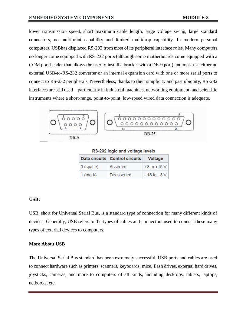
lower transmission speed, short maximum cable length, large voltage swing, large standard
connectors, no multipoint capability and limited multidrop capability. In modern personal
computers, USBhas displaced RS-232 from most of its peripheral interface roles. Many computers
no longer come equipped with RS-232 ports (although some motherboards come equipped with a
COM port header that allows the user to install a bracket with a DE-9 port) and must use either an
external USB-to-RS-232 converter or an internal expansion card with one or more serial ports to
connect to RS-232 peripherals. Nevertheless, thanks to their simplicity and past ubiquity, RS-232
interfaces are still used—particularly in industrial machines, networking equipment, and scientific
instruments where a short-range, point-to-point, low-speed wired data connection is adequate.
USB:
USB, short for Universal Serial Bus, is a standard type of connection for many different kinds of
devices. Generally, USB refers to the types of cables and connectors used to connect these many
types of external devices to computers.
More About USB
The Universal Serial Bus standard has been extremely successful. USB ports and cables are used
to connect hardware such as printers, scanners, keyboards, mice, flash drives, external hard drives,
joysticks, cameras, and more to computers of all kinds, including desktops, tablets, laptops,
netbooks, etc.

EMBEDDED SYSTEM COMPONENTS MODULE-3
In fact, USB has become so common that you'll find the connection available on nearly any
computer-like device such as video game consoles, home audio/visual equipment, and even in
many automobiles.
Many portable devices, like smartphones, ebook readers, and small tablets, use USB primarily for
charging. USB charging has become so common that it's now easy to find replacement electrical
outlets at home improvement stores with USB ports built it, negating the need for a USB power
adapter.
USB Versions
There have been three major USB standards, 3.1 being the newest:
USB 3.1: Called Superspeed+, USB 3.1 compliant devices are able to transfer data at 10
Gbps (10,240 Mbps).
USB 3.0: Called SuperSpeed USB, USB 3.0 compliant hardware can reach a maximum
transmission rate of 5 Gbps (5,120 Mbps).
USB 2.0: Called High-Speed USB, USB 2.0 compliant devices can reach a maximum
transmission rate of 480 Mbps.
USB 1.1: Called Full Speed USB, USB 1.1 devices can reach a maximum transmission rate
of 12 Mbps.
Most USB devices and cables today adhere to USB 2.0, and a growing number to USB 3.0.
Important: The parts of a USB-connected system, including the host (like a computer), the cable,
and the device, can all support different USB standards so long as they are physically compatible.
However, all parts must support the same standard if you want it to achieve the maximum data rate
possible.

EMBEDDED SYSTEM COMPONENTS MODULE-3
IEEE1394:
IEEE 1394, High Performance Serial Bus, is an electronics standard for connecting devices to your
personal computer. IEEE 1394 provides a single plug-and-socket connection on which up to 63
devices can be attached with data transfer speeds up to 400 Mbps ( megabit s per second). The
standard describes a serial bus or pathway between one or more peripheral devices and your
computer's microprocessor . Many peripheral devices now come equipped to meet IEEE 1394.
Two popular implementations of IEEE 1394 are Apple's FireWire and Sony's i.LINK . IEEE 1394
implementations provide:
A simple common plug-in serial connector on the back of your computer and on many different
types of peripheral devices
A thin serial cable rather than the thicker parallel cable you now use to your printer, for example
A very high-speed rate of data transfer that will accommodate multimedia applications (100
and 200 megabits per second today; with much higher rates later)
Hot-plug and plug and play capability without disrupting your computer
The ability to chain devices together in a number of different ways without terminators or
complicated set-up requirements
EMBEDDED SYSTEM COMPONENTS MODULE-3
Working
There are two levels of interface in IEEE 1394, one for the backplane bus within the computer and
another for the point-to-point interface between device and computer on the serial cable. A simple
bridge connects the two environments. The backplane bus supports 12.5, 25, or 50 megabits per
second data transfer. The cable interface supports 100, 200, or 400 megabits per second. Each of
these interfaces can handle any of the possible data rates and change from one to another as needed.
IrDA
IrDA (Infrared Data Association)
Bluetooth 2.4 GHz
802.11 WLAN and 802.11b WiFi
ZigBee 900 MHz
Used in mobile phones, digital cameras, keyboard, mouse, printers to communicate to
laptop computer and for data and pictures download and synchronization.
Used for control TV, air-conditioning, LCD projector, VCD devices from a distance
Use infrared (IR) after suitable modulation of the data bits.
Communicates over a line of sight Phototransistor receiver for infrared rays
IrDA protocol suite
Supports data transfer rates of up to 4 Mbps
Supports bi-directional serial communication over viewing angle between ± 15 ° and
distance of nearly 1 m At 5 m, the IR transfer data can be up to data transfer rates of 75
kbps
Should be no obstructions or wall in between the source and receiver
Bluetooth
Bluetooth is a wireless technology standard for exchanging data over short distances (using short-
wavelength UHF radio waves in the ISM band from 2.4 to 2.485 GHz) from fixed and mobile
devices, and building personal area networks(PANs). Invented by telecom vendor Ericsson in
1994, it was originally conceived as a wireless alternative to RS-232data cables.

EMBEDDED SYSTEM COMPONENTS MODULE-3
Bluetooth is managed by the Bluetooth Special Interest Group (SIG), which has more than 30,000
member companies in the areas of telecommunication, computing, networking, and consumer
electronics.[5] The IEEE standardized Bluetooth as IEEE 802.15.1, but no longer maintains the
standard. The Bluetooth SIG oversees development of the specification, manages the qualification
program, and protects the trademarks.[6] A manufacturer must meet Bluetooth SIG standards to
market it as a Bluetooth device.
Bluetooth operates at frequencies between 2402 and 2480 MHz, or 2400 and 2483.5 MHz
including guard bands 2 MHz wide at the bottom end and 3.5 MHz wide at the top.[15] This is in
the globally unlicensed (but not unregulated) industrial, scientific and medical (ISM) 2.4 GHz
short-range radio frequency band. Bluetooth uses a radio technology called frequency-hopping
spread spectrum. Bluetooth divides transmitted data into packets, and transmits each packet on one
of 79 designated Bluetooth channels. Each channel has a bandwidth of 1 MHz. It usually performs
800 hops per second, with Adaptive Frequency-Hopping (AFH) enabled. Bluetooth Low Energy
uses 2 MHz spacing, which accommodates 40 channels.
Originally, Gaussian frequency-shift keying (GFSK) modulation was the only modulation scheme
available. Since the introduction of Bluetooth 2.0+EDR, π/4-DQPSK(differential quadrature phase
shift keying) and 8DPSK modulation may also be used between compatible devices. Devices
functioning with GFSK are said to be operating in basic rate (BR) mode where an instantaneous bit
rate of 1 Mbit/s is possible. The term Enhanced Data Rate (EDR) is used to describe π/4-DPSK
and 8DPSK schemes, each giving 2 and 3 Mbit/s respectively. The combination of these (BR and
EDR) modes in Bluetooth radio technology is classified as a "BR/EDR radio".
Wifi :
Wi-Fi is a technology for wireless local area networking with devices based on the IEEE
802.11standards. Wi-Fi is a trademark of the Wi-Fi Alliance, which restricts the use of the term
Wi-Fi Certified to products that successfully complete interoperability certification testing.
Devices that can use Wi-Fi technology include personal computers, video-game consoles,
phones and tablets, digital cameras, smart TVs, digital audio players and modern printers. Wi-Fi
compatible devices can connect to the Internet via a WLAN and a wireless access point. Such an
access point (or hotspot) has a range of about 20 meters (66 feet) indoors and a

EMBEDDED SYSTEM COMPONENTS MODULE-3
greater range outdoors. Hotspot coverage can be as small as a single room with walls that block
radio waves, or as large as many square kilometres achieved by using multiple overlapping access
points.
Wi-Fi most commonly uses the 2.4 gigahertz (12 cm) UHF and 5.8 gigahertz (5
cm) SHF ISM radio bands. Anyone within range with a wireless modem can attempt to access the
network; because of this, Wi-Fi is more vulnerable to attack (called eavesdropping) than wired
networks. Wi-Fi Protected Access is a family of technologies created to protect information
moving across Wi-Fi networks and includes solutions for personal and enterprise networks.
Security features of Wi-Fi Protected Access constantly evolve to include stronger protections and
new security practices as the security landscape change.
Zigbee :
Zigbee is an IEEE 802.15.4-based specification for a suite of high-level communication protocols
used to create personal area networks with small, low-power digital radios, such as for home
automation, medical device data collection, and other low-power low-bandwidth needs, designed
for small scale projects which need wireless connection. Hence, Zigbee is a low-power, low data
rate, and close proximity (i.e., personal area) wireless ad hoc network.
The technology defined by the Zigbee specification is intended to be simpler and less expensive
than other wireless personal area networks (WPANs), such as Bluetooth or more general wireless
networking such as Wi-Fi. Applications include wireless light switches, home energy monitors,
traffic management systems, and other consumer and industrial equipment that requires short-
range low-rate wireless data transfer.
Its low power consumption limits transmission distances to 10–100 meters line-of-sight,
depending on power output and environmental characteristics. Zigbee devices can transmit data

EMBEDDED SYSTEM COMPONENTS MODULE-3
over long distances by passing data through a mesh network of intermediate devices to reach more
distant ones. Zigbee is typically used in low data rate applications that require long battery life and
secure networking (Zigbee networks are secured by 128 bit symmetric encryption keys.) Zigbee
has a defined rate of 250 kbit/s, best suited for intermittent data transmissions from a sensor or
input device.
Zigbee was conceived in 1998, standardized in 2003, and revised in 2006. The name refers to the
waggle dance of honey bees after their return to the beehive.
Typical application areas include:
Home Entertainment and Control—Home automation such as in QIVICON,[11] smart
lighting,[12] advanced temperature control, safety and security, movies and music
Wireless sensor networks—Starting with individual sensors like Telosb/Tmote and Iris from
Memsic
Industrial control
Embedded sensing
Medical data collection
Smoke and intruder warning
Building automation
Remote wireless microphone configuration, in Shure Wireless Microphone Systems [13]
General Packet Radio Service:
GPRS is a packet oriented mobile data service on the 2G and 3G cellular communication
system's global system for mobile communications (GSM). GPRS was originally standardized
by European Telecommunications Standards Institute (ETSI) in response to the earlier CDPD
and i-modepacket-switched cellular technologies. It is now maintained by the 3rd Generation
Partnership Project (3GPP).
GPRS usage is typically charged based on volume of data transferred, contrasting with circuit
switched data, which is usually billed per minute of connection time. Sometimes billing time
is broken down to every third of a minute. Usage above the bundle cap is charged per
megabyte, speed limited, or disallowed.

EMBEDDED SYSTEM COMPONENTS MODULE-3
GPRS is a best-effort service, implying variable throughput and latency that depend on the
number of other users sharing the service concurrently, as opposed to circuit switching, where
a certain quality of service (QoS) is guaranteed during the connection. In 2G systems, GPRS
provides data rates of 56–114 kbit/second.[ 2G cellular technology combined with GPRS is
sometimes described as 2.5G, that is, a technology between the second (2G) and third (3G)
generations of mobile telephony. It provides moderate-speed data transfer, by using unused
time division multiple access (TDMA) channels in, for example, the GSM system. GPRS is
integrated into GSM Release 97 and newer releases.
MEMORIES
There are different types of memories available to be used in computers as well as embedded
system. This chapter guides the reader through the different types of memories that are available
and can be used and tries to explain their differences in simple words.
TYPES OF MEMORY
There are three main types of memories, they are
a) RAM (Random Access Memory) It is read write memory.
Data at any memory location can be read or written.
It is volatile memory, i.e. retains the contents as long as electricity is supplied.
Data access to RAM is very fast
b) ROM (Read Only Memory) It is read only memory.
Data at any memory location can be only read.
It is non-volatile memory, i.e. the contents are retained even after electricity is switched off
and available after it is switched on. Data access to ROM is slow compared to RAM.
c) HYBRID It is combination of RAM as well as ROM
It has certain features of RAM and some of ROM
Like RAM the contents to hybrid memory can be read and written Like ROM the contents
of hybrid memory are non volatile

EMBEDDED SYSTEM COMPONENTS MODULE-3
The following figure gives a classification of different types of memory
TYPES OF RAM
There are 2 important memory device in the RAM family.
a) SRAM (Static RAM)
b) DRAM (Dynamic RAM)
SRAM (Static RAM)
It retains the content as long as the power is applied to the chip.
If the power is turned off then its contents will be lost forever.
DRAM (Dynamic RAM)
DRAM has extremely short Data lifetime(usually less than a quarter of second).
This is true even when power is applied constantly.
b) A DRAM controller is used to make DRAM behave more like SRAM.
c) The DRAM controller periodically refreshes the data stored in the DRAM. By
refreshing the data several times a second, the DRAM controller keeps the contents
of memory alive for a long time.
EMBEDDED SYSTEM COMPONENTS MODULE-3
TYPES OF ROM
There are three types of ROM described as follows:
Masked ROM
a. These are hardwired memory devices found on system. b. It contains pre-programmed
set of instruction and data and it cannot be modified or appended in any way.
b. (it is just like an Audio CD that contains songs pre-written on it and does not allow to
write any other data)
c. The main advantage of masked ROM is low cost of production.
PROM (PROGRAMMABLE ROM )
a) This memory device comes in an un-programmed state i.e. at the time of purchased it is
in an un-programmed state and it allows the user to write his/her own program or code into
this ROM.
b) In the un-programmed state the data is entirely made up of 1’s. c) PROMs are also
known as one-time-programmable (OTP) device because any data can be written on it only
once. If the data on the chip has some error and needs to be modified this memory chip has
to be discarded and the modified data has to be written to another new PROM.
EPROM (ERASABLE-AND-PROGRAMABLE ROM)
a) It is same as PROM and is programmed in same manner as a PROM.
b) It can be erased and reprogrammed repeatedly as the name suggests.
c) The erase operation in case of an EPROM is performed by exposing the chip to a source
of ultraviolet light.
d) The reprogramming ability makes EPROM as essential part of software development
and testing process.

EMBEDDED SYSTEM COMPONENTS MODULE-3
TYPES OF HYBRID MEMORY
There are three types of Hybrid memory devices: EEPROMs
a. EEPROMs stand for Electrically Erasable and Programmable ROM.
b. It is same as EPROM, but the erase operation is performed electrically.
c. Any byte in EEPROM can be erased and rewritten as desired
Flash
a. Flash memory is the most recent advancement in memory technology.
b. Flash memory devices are high density, low cost, nonvolatile, fast (to read, but not to
write), and electrically reprogrammable.
c. Flash is much more popular than EEPROM and is rapidly displacing many of the ROM
devices.
d. Flash devices can be erased only one sector at a time, not byte by byte.
NVRAM
a. NVRAM is usually just a SRAM with battery backup.
b. When power is turned on, the NVRAM operates just like any other SRAM but when
power is off, the NVRAM draws enough electrical power from the battery to retain its
content.
c. NVRAM is fairly common in embedded systems.
d. It is more expensive than SRAM.
DIRECT MEMORY ACCESS (DMA)
DMA is a technique for transferring blocks of data directly between two hardware
devices. In the absence of DMA the processor must read the data from one device and write
it to the other one byte or word at a time. DMA Absence Disadvantage: If the amount of data
to be transferred is large or frequency of transfer is high the rest of the software might never
get a chance to run.

EMBEDDED SYSTEM COMPONENTS MODULE-3
DMA Presence Advantage: The DMA Controller performs entire transfer with little help
from the Processor. Working of DMA The Processor provides the DMA Controller with
source and destination address & total number of bytes of the block of data which needs
transfer. After copying each byte each address is incremented & remaining bytes are
reduced by one. When number of bytes reaches zeros the block transfer ends & DMA
Controller sends an Interrupt to Processor.
EMBEDDED FIRMWARE
Embedded firmware is the flash memory chip that stores specialized software running in a chip in
an embedded device to control its functions.
Firmware in embedded systems fills the same purpose as a ROM but can be updated more easily
for better adaptability to conditions or interconnecting with additional equipment.
Hardware makers use embedded firmware to control the functions of various hardware devices
and systems much like a computer’s operating system controls the function of software
applications. Embedded firmware exists in everything from appliances so simple you might not
imagine they had computer control, like toasters, to complex tracking systems in missiles. The
toaster would likely never need updating but the tracking system sometimes does. As the
complexity of a device increases, it often makes sense to use firmware in case of design errors that
an update might correct.
Embedded firmware is used to control the limited, set functions of hardware devices and systems
of greater complexity but still gives more appliance-like usage instead of a series of terminal
commands. Embedded firmware functions are activated by external controls or external actions of
the hardware. Embedded firmware and ROM-based embedded software often have
communication links to other devices for functionality or to address the need for the device to be
adjusted, calibrated or diagnosed or to output log files. It is also through these connections that
someone might attempt embedded device hacking.
Embedded software varies in complexity as much the devices it is used to control. Although
embedded software and embedded firmware are sometimes used synonymously, they

EMBEDDED SYSTEM COMPONENTS MODULE-3
are not exactly the same thing. For example, embedded software may run on ROM chips. Also,
embedded software is often the only computer code running on a piece of hardware while firmware
can also refer to the chip that houses a computer’s EFI or BIOS, which hands over control to an
OS that in turn launches and controls programs.
Other components :
Reset circuit:
Microprocessors are complex, state-driven devices that must start up in a consistent way to
function properly. You can establish proper processor operation by supplying a reset input
that is normally asserted until the system is ready to execute the boot-up firmware. When the
reset signal is deasserted, some subset of the processor's registers (depending on the specific
chip) will be initialized to default values and the processor will start executing from fixed
location (also specific to the chip). It's crucial to design this reset circuit properly to avoid
system lockup, erratic processor operation, and possible corruption of your nonvolatile
memory.
This is all complex enough that many companies now offer integrated circuit reset devices,
commonly referred to as "reset supervisors." Good design practice suggests using these reset
supervisors for most embedded systems because designing discrete reset circuitry is beyond
the expertise of many embedded systems engineers. My personal experience has led me to
rely on reset supervisors exclusively and ignore the various RC, transistor, and diode networks
that are scattered throughout data books and shown in "example" circuits.

EMBEDDED SYSTEM COMPONENTS MODULE-3
Brownout Protection
Brownout protection inbuilt in them but when connecting a controller to an industry sensor and
controlling devices(which are extremely costly) its better we know what is a brownout and how is
it detected in a microcontroller cause many devices in low to medium scale industry may not be
as immune to brownout as our controller. The brown out can cause one of the three things for a dc
supply system. These things in turn can damage the connected embedded systems.
1. An unregulated direct current supply will produce a lower output voltage for
electronic circuits. The output ripple voltage will decrease in line with the usually reduced
load current.
2. A linear direct current regulated supply will maintain the output voltage unless the
brownout is severe and the input voltage drops below the drop out voltage for the regulator,
at which point the output voltage will fall and high levels of ripple from the
rectifier/reservoir capacitor will appear on the output.
3. A switched-mode power supply which has a regulated output will be affected. As
the input voltage falls, the current draw will increase to maintain the same output voltage
and current, until such a point that the power supply malfunctions.

EMBEDDED SYSTEM COMPONENTS MODULE-3
Oscillator circuit :
The majority of clock sources for microcontrollers can be grouped into two types: those
based on mechanical resonant devices, such as crystals and ceramic resonators, and those
based on electrical phase-shift circuits such as RC (resistor, capacitor) oscillators. Silicon
oscillators are typically a fully integrated version of the RC oscillator with the added
benefits of current sources, matched resistors and capacitors, and temperature-
compensation circuits for increased stability.
These modules contain all oscillator circuit components and provide a clock signal as a
low-impedance square-wave output. Operation is guaranteed over a range of conditions.
Crystal oscillator modules and fully integrated silicon oscillators are most common. Crystal
oscillator modules provide accuracy similar to discrete component circuits using crystals.
Silicon oscillators are more precise than discrete component RC oscillator circuits, and
many provide comparable accuracy to ceramic resonator-based oscillators.

EMBEDDED SYSTEM COMPONENTS MODULE-3
RTC
A real-time clock (RTC) is a computer clock (most often in the form of an integrated circuit) that
keeps track of the current time.
Although the term often refers to the devices in personal computers, servers and embedded
systems, RTCs are present in almost any electronic device which needs to keep accurate time. A
common RTC used in single-board computers is the DS1307.
Although keeping time can be done without an RTC,[1] using one has benefits:
Low power consumption[2] (important when running from alternate power)
Frees the main system for time-critical tasks
Sometimes more accurate than other methods
RTCs are widely used in many different devices which need accurate time keeping.
Real-time clocks normally have batteries attached to them that have very long life.
Therefore, the batteries last a very long time, several years. The battery keeps the RTC
operating, even when there is no power to the microcontroller that is connected up to. So
even if the microcontroller powers off, the RTC can keep operating due to its battery.
Therefore, it can always keep track of the current time and have accurate time, ongoing.
An RTC maintains its clock by counting the cycles of an oscillator – usually an external 32.768kHz
crystal oscillator circuit, an internal capacitor based oscillator, or even an embedded quartz crystal.
Some can detect transitions and count the periodicity of an input that may be connected.
This can enable an RTC to sense the 50/60Hz ripple on a mains power supply, or detect and
accumulate transitions coming from a GPS unit epoch tick. An RTC that does this operates like a
phase locked loop (PLL), shifting its internal clock reference to ‘lock’ it onto the external signal.
If the RTC loses its external reference, it can detect this event (as its PLL goes out of lock) and
free run from its internal oscillator.

EMBEDDED SYSTEM COMPONENTS MODULE-3
A watchdog timer (WDT):
WDT is a hardware timer that automatically generates a system reset if the main program
neglects to periodically service it. It is often used to automatically reset an embedded device
that hangs because of a software or hardware fault. Some systems may also refer to it as a
computer operating properly (COP) timer. Many microcontrollers including the embedded
processor have watchdog timer hardware.
The main program typically has a loop that it constantly goes through performing various
functions. The watchdog timer is loaded with an initial value greater than the worst case time
delay through the main program loop. Each time it goes through the main loop the code resets
the watchdog timer (sometimes called “kicking” or “feeding” the dog). If a fault occurs and the
main program does not get back to reset the timer before it counts down, an interrupt is
generated to reset the processor. Used in this way, the watchdog timer can detect a fault on an
unattended embedded device and attempt corrective action with a reset. Typically after reset, a
register can also be read to determine if the watchdog timer generated the reset or if it was a
normal reset. On the mbed this register is called the Reset Source Identification Register
(RSID).

EMBEDDED SYSTEM COMPONENTS MODULE-3

EMBEDDED SYSTEM DESIGN CONCEPTS MODULE-4
EMBEDDED SYSTEM DESIGN CONCEPTS
Characteristics & Quality Attributes of Embedded Systems
The characteristics of embedded system are different from those of a general purpose computer and so
are its Quality metrics. This chapter gives a brief introduction on the characteristics of an embedded
system and the attributes that are associated with its quality.
CHARACTERISTICS OF EMBEDDED SYSTEM
Following are some of the characteristics of an embedded system that make it different from a
general purpose computer:
1. Application and Domain specific
An embedded system is designed for a specific purpose only. It will not do any other task.
Ex. A washing machine can only wash, it cannot cook
Certain embedded systems are specific to a domain: ex. A hearing aid is an application that
belongs to the domain of signal processing.
2. Reactive and Real time
Certain Embedded systems are designed to react to the events that occur in the nearby
environment. These events also occur real-time.
Ex. An air conditioner adjusts its mechanical parts as soon as it gets a signal from its sensors
to increase or decrease the temperature when the user operates it using a remote control.
An embedded system uses Sensors to take inputs and has actuators to bring out the required
functionality.
3. Operation in harsh environment
Certain embedded systems are designed to operate in harsh environments like very high
temperature of the deserts or very low temperature of the mountains or extreme rains.
These embedded systems have to be capable of sustaining the environmental conditions it
is designed to operate in.

EMBEDDED SYSTEM DESIGN CONCEPTS MODULE-4
4. Distributed systems
Certain embedded systems are part of a larger system and thus form components of a
distributed system.
These components are independent of each other but have to work together for the larger
system to function properly.
Ex. A car has many embedded systems controlled to its dash board. Each one is an
independent embedded system yet the entire car can be said to function properly only if all
the systems work together.
5. Small size and weight
An embedded system that is compact in size and has light weight will be desirable or more
popular than one that is bulky and heavy.
Ex. Currently available cell phones. The cell phones that have the maximum features are
popular but also their size and weight is an important characteristic

EMBEDDED SYSTEM DESIGN CONCEPTS MODULE-4
6. Power concerns
It is desirable that the power utilization and heat dissipation of any embedded system be
low.
If more heat is dissipated then additional units like heat sinks or cooling fans need to be
added to the circuit.
If more power is required then a battery of higher power or more batteries need to be
accommodated in the embedded system
QUALITY ATTRIBUTES OF EMBEDDED SYSTEM
These are the attributes that together form the deciding factor about the quality of an embedded
system.
There are two types of quality attributes are:-
1. Operational Quality Attributes.
These are attributes related to operation or functioning of an embedded system. The way
an embedded system operates affects its overall quality.
2. Non-Operational Quality Attributes.
These are attributes not related to operation or functioning of an embedded system. The
way an embedded system operates affects its overall quality.
These are the attributes that are associated with the embedded system before it can be put
in operation.
Operational Attributes
a) Response
Response is a measure of quickness of the system.
It gives you an idea about how fast your system is tracking the input variables.
Most of the embedded system demand fast response which should be real-time.
b) Throughput
Throughput deals with the efficiency of system.
It can be defined as rate of production or process of a defined process over a stated period
of time.

EMBEDDED SYSTEM DESIGN CONCEPTS MODULE-4
In case of card reader like the ones used in buses, throughput means how much transaction
the reader can perform in a minute or hour or day.

EMBEDDED SYSTEM DESIGN CONCEPTS MODULE-4

EMBEDDED SYSTEM DESIGN CONCEPTS MODULE-4
c) Reliability
Reliability is a measure of how much percentage you rely upon the proper functioning of
the system .
Mean Time between failures and Mean Time To Repair are terms used in defining system
reliability.
Mean Time between failures can be defined as the average time the system is functioning
before a failure occurs.
Mean time to repair can be defined as the average time the system has spent in repairs.
d) Maintainability
Maintainability deals with support and maintenance to the end user or a client in case of
technical issues and product failures or on the basis of a routine system checkup
It can be classified into two types :-
1. Scheduled or Periodic Maintenance
This is the maintenance that is required regularly after a periodic time interval.
Example : Periodic Cleaning of Air Conditioners Refilling of printer cartridges.
2. Maintenance to unexpected failure
This involves the maintenance due to a sudden breakdown in the functioning of the system.
Example:
1. Air conditioner not powering on
2. Printer not taking paper in spite of a full paper stack
e) Security
Confidentiality, Integrity and Availability are three corner stones of information security.
Confidentiality deals with protection data from unauthorized disclosure.
Integrity gives protection from unauthorized modification.
Availability gives protection from unauthorized user
Certain Embedded systems have to make sure they conform to the security measures.
EMBEDDED SYSTEM DESIGN CONCEPTS MODULE-4
Ex. An Electronic Safety Deposit Locker can be used only with a pin number like a
password.
f) Safety
Safety deals with the possible damage that can happen to the operating person and
environment due to the breakdown of an embedded system or due to the emission of
hazardous materials from the embedded products.

EMBEDDED SYSTEM DESIGN CONCEPTS MODULE-4
A safety analysis is a must in product engineering to evaluate the anticipated damage and
determine the best course of action to bring down the consequence of damages to an
acceptable level.
Non Operational Attributes
a) Testability and Debug-ability
It deals with how easily one can test his/her design, application and by which mean he/she
can test it.
In hardware testing the peripherals and total hardware function in designed manner
Firmware testing is functioning in expected way
Debug-ability is means of debugging the product as such for figuring out the probable
sources that create unexpected behavior in the total system
b) Evolvability
For embedded system, the qualitative attribute “Evolvability” refer to ease with which the
embedded product can be modified to take advantage of new firmware or hardware
technology.
c) Portability
Portability is measured of “system Independence”.
An embedded product can be called portable if it is capable of performing its operation as
it is intended to do in various environments irrespective of different processor and or
controller and embedded operating systems.
d) Time to prototype and market
Time to Market is the time elapsed between the conceptualization of a product and time at
which the product is ready for selling or use
Product prototyping help in reducing time to market.
Prototyping is an informal kind of rapid product development in which important feature
of the under consider are develop.

EMBEDDED SYSTEM DESIGN CONCEPTS MODULE-4
In order to shorten the time to prototype, make use of all possible option like use of reuse,
off the self component etc.
e) Per unit and total cost
Cost is an important factor which needs to be carefully monitored. Proper market study and
cost benefit analysis should be carried out before taking decision on the per unit cost of the
embedded product.
When the product is introduced in the market, for the initial period the sales and revenue
will be low
There won’t be much competition when the product sales and revenue increase.
During the maturing phase, the growth will be steady and revenue reaches highest point
and at retirement time there will be a drop in sales volume.
Embedded Systems-Application and Domain specific
Application specific systems : Washing Machine
Let us see the important parts of the washing machine; this will also help us understand the working
of the washing machine:
1) Water inlet control valve: Near the water inlet point of the washing there is water inlet control
valve. When you load the clothes in washing machine, this valve gets opened automatically and it
closes automatically depending on the total quantity of the water required. The water control valve
is actually the solenoid valve.

EMBEDDED SYSTEM DESIGN CONCEPTS MODULE-4
2) Water pump: The water pump circulates water through the washing machine. It works in two
directions, re-circulating the water during wash cycle and draining the water during the spin cycle.

EMBEDDED SYSTEM DESIGN CONCEPTS MODULE-4
3) Tub: There are two types of tubs in the washing washing machine: inner and outer. The clothes
are loaded in the inner tub, where the clothes are washed, rinsed and dried. The inner tub has small
holes for draining the water. The external tub covers theinner tub and supports it during various
cycles of clothes washing.
4) Agitator or rotating disc: The agitator is located inside the tub of the washing machine. It is
the important part of the washing machine that actually performs the cleaning operation of the
clothes. During the wash cycle the agitator rotates continuously and produces strong rotating
currents within the water due to which the clothes also rotate inside the tub. The rotation of the
clothes within water containing the detergent enables the removal of the dirt particles from the
fabric of the clothes. Thus the agitator produces most important function of rubbing the clothes
with each other as well as with water.
In some washing machines, instead of the long agitator, there is a disc that contains blades on its
upper side. The rotation of the disc and the blades produce strong currents within the water and
the rubbing of clothes that helps in removing the dirt from clothes.
5) Motor of the washing machine: The motor is coupled to the agitator or the disc and produces
it rotator motion. These are multispeed motors, whose speed can be changed as per the
requirement. In the fully automatic washing machine the speed of the motor i.e. the agitator
changes automatically as per the load on the washing machine.
6) Timer: The timer helps setting the wash time for the clothes manually. In the automatic mode
the time is set automatically depending upon the number of clothes inside the washing machine.
7) Printed circuit board (PCB): The PCB comprises of the various electronic components and
circuits, which are programmed to perform in unique ways depending on the load conditions (the
condition and the amount of clothes loaded in the washing machine). They are sort of artificial
intelligence devices that sense the various external conditions and take the decisions accordingly.
These are also called as fuzzy logic systems. Thus the PCB will calculate the total weight of the
clothes, and find out the quantity of water and detergent required, and the total time required for
washing the clothes. Then they will decide the time required for washing and rinsing. The entire
processing is done on a kind of processor which may be a microprocessor or microcontroller.

EMBEDDED SYSTEM DESIGN CONCEPTS MODULE-4
8) Drain pipe: The drain pipe enables removing the dirty water from the washing that has been
used for the washing purpose.
Automotive Embedded System (AES)
The Automotive industry is one of the major application domains of embedded systems.
Automotive embedded systems are the one where electronics take control over the
mechanical system. Ex. Simple viper control.
The number of embedded controllers in a normal vehicle varies somewhere between 20 to
40 and can easily be between 75 to 100 for more sophisticated vehicles.
One of the first and very popular use of embedded system in automotive industry was
microprocessor based fuel injection.
Some of the other uses of embedded controllers in a vehicle are listed below:
a. Air Conditioner
b. Engine Control
c. Fan Control
d. Headlamp Control
e. Automatic break system control
f. Wiper control
g. Air bag control
h. Power Windows
AES are normally built around microcontrollers or DSPs or a hybrid of the two and are generally
known as Electronic Control Units (ECUs).

EMBEDDED SYSTEM DESIGN CONCEPTS MODULE-4
Types Of Electronic Control Units(ECU)
1. High-speed Electronic Control Units (HECUs):
a. HECUs are deployed in critical control units requiring fast response.
b. They Include fuel injection systems, antilock brake systems, engine control, electronic throttle,
steering controls, transmission control and central control units.
2. Low Speed Electronic Control Units (LECUs):-
a. They are deployed in applications where response time is not so critical.
b. They are built around low cost microprocessors and microcontrollers and digital signal
processors.
c. Audio controller, passenger and driver door locks, door glass control etc.
Automotive Communication Buses
Embedded system used inside an automobile communicate with each other using serial buses. This
reduces the wiring required.
Following are the different types of serial Interfaces used in automotive embedded applications:
a. Controller Area Network (CAN):-
CAN bus was originally proposed by Robert Bosch.
It supports medium speed and high speed data transfer
CAN is an event driven protocol interface with support for error handling in data
transmission.
b. Local Interconnect Network (LIN):-
LIN bus is single master multiple slave communication interface with support for data rates
up to 20 Kbps and is used for sensor/actuator interfacing

EMBEDDED SYSTEM DESIGN CONCEPTS MODULE-4
LIN bus follows the master communication triggering to eliminate the bus arbitration
problem
LIN bus applications are mirror controls , fan controls , seat positioning controls
c. Media-Oriented System Transport(MOST):-
MOST is targeted for automotive audio/video equipment interfacing
A MOST bus is a multimedia fiber optics point–to- point network implemented in a star ,
ring or daisy chained topology over optical fiber cables.
MOST bus specifications define the physical as well as application layer , network layer
and media access control.

RTOS AND IDE FOR ESD MODULE-5
What Is OS ?
An Operating System (OS) is an interface between computer user and computer hardware. An operating system
is software which performs all the basic tasks like file management, memory management, process management,
handling input and output, and controlling peripheral devices such as disk drives and printers. Some popular
Operating Systems include Linux Operating System, Windows Operating System, VMS, OS/400, AIX, z/OS, etc.
Definition:
An operating system is a program that acts as an interface between the user and the computer hardware and
controls the execution of all kinds of programs.
Following are some of important functions of an operating System.
Memory Management Processor Management Device Management File Management Security
Control over system performance Job accounting Error detecting aids Coordination between other
software and users

RTOS AND IDE FOR ESD MODULE-5
An Operating System provides services to both the users and to the programs. It provides programs an
environment to execute.
It provides users the services to execute the programs in a convenient manner.
Following are a few common services provided by an operating system: Program execution
I/O operations
File System manipulation
Communication
Error Detection
Resource Allocation
Protection
Basic Functions of Operation System:
The various functions of operating system are as follows:
1. Process Management:
A program does nothing unless their instructions are executed by a CPU.A process is a program
in execution. A time shared user program such as a complier is a process. A word processing
program being run by an individual user on a pc is a process.
A system task such as sending output to a printer is also a process. A process needs certain
resources including CPU time, memory files & I/O devices to accomplish its task.
These resources are either given to the process when it is created or allocated to it while it is
running. The OS is responsible for the following activities of process management.
Creating & deleting both user & system processes.
Suspending & resuming processes.
Providing mechanism for process synchronization.
Providing mechanism for process communication.
Providing mechanism for deadlock handling.
2. Main Memory Management:
The main memory is central to the operation of a modern computer system. Main memory is a

RTOS AND IDE FOR ESD MODULE-5
large array of words or bytes ranging in size from hundreds of thousand to billions. Main memory
stores the quickly accessible data shared by the CPU & I/O device. The central processor reads
instruction from main memory during instruction fetch cycle & it both reads
&writes data from main memory during the data fetch cycle. The main memory is generally the only
large storage device that the CPU is able to address & access directly. For example, for the CPU to
process data from disk. Those data must first be transferred to main memory by CPU generated
E/O calls. Instruction must be in memory for the CPU to execute them. The OS is responsible for
the following activities in connection with memory management.
Keeping track of which parts of memory are currently being used & by whom.
Deciding which processes are to be loaded into memory when memory space becomes
available.
Allocating &deal locating memory space as needed.
3. File Management:
File management is one of the most important components of an OS computer can store
information on several different types of physical media magnetic tape, magnetic disk & optical disk
are the most common media. Each medium is controlled by a device such as disk drive or tape drive
those has unique characteristics. These characteristics include access speed, capacity, data transfer
rate & access method (sequential or random).For convenient use of computer system the OS
provides a uniform logical view of information storage. The OS abstracts from the physical
properties of its storage devices to define a logical storage unit the file. A file is collection of related
information defined by its creator. The OS is responsible for the following activities of file
management.
Creating & deleting files.
Creating & deleting directories.
Supporting primitives for manipulating files & directories.
Mapping files into secondary storage.
Backing up files on non-volatile media.
4. I/O System Management:
One of the purposes of an OS is to hide the peculiarities of specific hardware devices from the user.
For example, in UNIX the peculiarities of I/O devices are hidden from the bulk of the OS itself by
the I/O subsystem. The I/O subsystem consists of:
A memory management component that includes buffering, catching & spooling.

RTOS AND IDE FOR ESD MODULE-5
A general device- driver interfaces drivers for specific hardware devices. Only the device
driver knows the peculiarities of the specific device to which it is assigned.

RTOS AND IDE FOR ESD MODULE-5
5. Secondary Storage Management:
The main purpose of computer system is to execute programs. These programs with the data
they access must be in main memory during execution. As the main memory is too small to
accommodate all data & programs & because the data that it holds are lost when power is
lost. The computer system must provide secondary storage to back-up main memory. Most
modern computer systems are disks as the storage medium to store data & program. The
operating system is responsible for the following activities of disk management.
Free space management.
Storage allocation.
Disk scheduling
Because secondary storage is used frequently it must be used efficiently.
Networking:
A distributed system is a collection of processors that don’t share memory peripheral devices or
a clock. Each processor has its own local memory & clock and the processor communicate with
one another through various communication lines such as high speed buses or networks. The
processors in the system are connected through communication networks which are configured
in a number of different ways. The communication network design must consider message
routing & connection strategies are the problems of connection & security.
Protection or security:
If a computer system has multi users & allow the concurrent execution of multiple processes
then the various processes must be protected from one another’s activities. For that purpose,
mechanisms ensure that files, memory segments, CPU & other resources can be operated on by
only those processes that have gained proper authorization from the OS.
Command interpretation:
One of the most important functions of the OS is connected interpretation where it acts as the
interface between the user & the OS.

RTOS AND IDE FOR ESD MODULE-5
Monolithic Operating Systems:
• Oldest kind of OS structure (“modern” examples are DOS, original MacOS)
• Problem: applications can e.g. – trash OS software. – trash another application. – hoard CPU time. –
abuse I/O devices. – Etc.
• No good for fault containment (or multi-user).

RTOS AND IDE FOR ESD MODULE-5
• Need a better solution.
Microkernel Operating Systems:
Alternative structure: – push some OS services into servers. – servers may be privileged (i.e.
operate in kernel mode).
• Increases both modularity and extensibility.
• Still access kernel via system calls, but need new way to access servers: ⇒ inter-process
communication (IPC) schemes

RTOS AND IDE FOR ESD MODULE-5
Real time Systems:
Real time system is used when there are rigid time requirements on the operation of a processor or flow
of data. Sensors bring data to the computers. The computer analyzes data and adjusts controls to modify
the sensors inputs. System that controls scientific experiments, medical imaging systems and some display
systems are real time systems. The disadvantages of real time system are: a. A real time system is
considered to function correctly only if it returns the correct result within the time constraints.
b. Secondary storage is limited or missing instead data is usually stored in short term memory or ROM. c.
Advanced OS features are absent. Real time system is of two types such as
• Hard real time systems: It guarantees that the critical task has been completed on time. The sudden
task is takes place at a sudden instant of time.
• Soft real time systems: It is a less restrictive type of real time system where a critical task gets priority
over other tasks and retains that priority until it computes. These have more limited utility than hard real
time systems. Missing an occasional deadline is acceptable e.g. QNX, VX works. Digital audio or multimedia
is included in this category. It is a special purpose OS in which there are rigid time requirements on the
operation of a processor. A real time OS has well defined fixed time constraints. Processing must be done
within the time constraint or the system will fail. A real time system is said to function correctly only if it
returns the correct result within the time constraint. These systems are characterized by having time as a
key parameter.
Task :
Task is a piece of code or program that is separate from another task and can be
executed independently of the other tasks.
In embedded systems, the operating system has to deal with a limited number of
tasks depending on the functionality to be implemented in the embedded system.

RTOS AND IDE FOR ESD MODULE-5
Multiple tasks are not executed at the same time instead they are executed in pseudo
parallel i.e. the tasks execute in turns as the use the processor.
From a multitasking point of view, executing multiple tasks is like a single book being
read by multiple people, at a time only one person can read it and then take turns to
read it.
Different bookmarks may be used to help a reader identify where to resume reading
next time.
An Operating System decides which task to execute in case there are multiple tasks
to be executed. The operating system maintains information about every task and
information about the state of each task.
The information about a task is recorded in a data structure called the task context.
When a task is executing, it uses the processor and the registers available for all sorts
of processing. When a task leaves the processor for another task to execute before it
has finished its own, it should resume at a later time from where it stopped and not
from the first instruction. This requires the information about the task with respect
to the registers of the processor to be stored somewhere. This information is
recorded in the task context.
Task States In an operation system there are always multiple tasks. At a time only one task can be executed.
This means that there are other tasks which are waiting their turn to be
executed.
Depending upon execution or not a task may be classified into the following three states:
Running state - Only one task can actually be using the processor at a given time that task
is said to be the “running” task and its state is “running state”. No other task can be in that
same state at the same time
Ready state - Tasks that are not currently using the processor but are ready to run are in the
“ready” state. There may be a queue of tasks in the ready state.
Waiting state - Tasks that are neither in running nor ready state but that are waiting for
some event external to themselves to occur before the can go for execution on are in the
“waiting” state.

RTOS AND IDE FOR ESD MODULE-5
Process Concept:
Process: A process or task is an instance of a program in execution. The execution of a process
must programs in a sequential manner. At any time at most one instruction is executed. The
process includes the current activity as represented by the value of the program counter and the
content of the processors registers. Also it includes the process stack which contain temporary
data (such as method parameters return address and local variables) & a data section which
contain global variables.
Difference between process & program:
A program by itself is not a process. A program in execution is known as a process. A program
is a passive entity, such as the contents of a file stored on disk where as process is an active entity
with a program counter specifying the next instruction to execute and a set of associated
resources may be shared among several process with some scheduling algorithm being used to
determinate when the stop work on one process and service a different one.
Process state: As a process executes, it changes state. The state of a process is defined by the
correct activity of that process. Each process may be in one of the following states.
New: The process is being created.
Ready: The process is waiting to be assigned to a processor.
Running: Instructions are being executed.
Waiting: The process is waiting for some event to occur.
Terminated: The process has finished execution.
Many processes may be in ready and waiting state at the same time. But only one process can

RTOS AND IDE FOR ESD MODULE-5
be running on any processor at any instant.
Process scheduling:
Scheduling is a fundamental function of OS. When a computer is multiprogrammed, it has
multiple processes completing for the CPU at the same time. If only one CPU is available, then
a choice has to be made regarding which process to execute next. This decision making process
is known as scheduling and the part of the OS that makes this choice is called a scheduler. The
algorithm it uses in making this choice is called scheduling algorithm.
Scheduling queues: As processes enter the system, they are put into a job queue. This queue
consists of all process in the system. The process that are residing in main memory and are
ready & waiting to execute or kept on a list called ready queue.
Process control block:
Each process is represented in the OS by a process control block. It is also by a process
control block. It is also known as task control block.
RTOS AND IDE FOR ESD MODULE-5
A process control block contains many pieces of information associated with a specific
process. It includes the following informations.
Process state: The state may be new, ready, running, waiting or terminated state.
Program counter:it indicates the address of the next instruction to be executed
for this purpose.
CPU registers: The registers vary in number & type depending on the computer
architecture. It includes accumulators, index registers, stack pointer & general
purpose registers, plus any condition- code information must be saved when an
interrupt occurs to allow the process to be continued correctly after- ward.
CPU scheduling information:This information includes process priority pointers
to scheduling queues & any other scheduling parameters.
Memory management information: This information may include such
information as the value of the bar & limit registers, the page tables or the
segment tables, depending upon the memory system used by the operating
system.
Accounting information: This information includes the amount of CPU and real
time used, time limits, account number, job or process numbers and so on.
I/O Status Information: This information includes the list of I/O devices allocated to this
process, a list of open files and so on. The PCB simply serves as the repository for any
information that may vary from process to process

RTOS AND IDE FOR ESD MODULE-5
Threads :
Applications use concurrent processes to speed up their operation. However,
switching between processes within an application incurs high process switching
overhead because the size of the process state information is large, so operating
system designers developed an alternative model of execution of a program, called
a thread, that could provide concurrency within an application with less overhead
To understand the notion of threads, let us analyze process switching overhead and see where a saving can be made. Process switching overhead has two components:
• Execution related overhead: The CPU state of the running process has to be saved and the CPU state of the new process has to be loaded in the CPU. This overhead is unavoidable.
• Resource-use related overhead: The process context also has to be
switched. It involves switching of the information about resources
allocated to the process, such as memory and files, and interaction
of the process with other processes. The large size of this
information adds to the process switching overhead.
Consider child processes Pi and Pj of the primary process of an application.
These processes inherit the context of their parent process. If none of these
processes have allocated any resources of their own, their context is identical;
their state information differs only in their CPU states and contents of their
stacks. Consequently, while switching between Pi and Pj ,much of the saving
and loading of process state information is redundant. Threads exploit this
feature to reduce the switching overhead.
A process creates a thread through a system call. The thread does not have
resources of its own, so it does not have a context; it operates by using the
context of the process, and accesses the resources of the process through it.
We use the phrases ―thread(s) of a process‖ and ―parent process of a thread‖
to describe the relationship between a thread and the process whose context
it uses.

RTOS AND IDE FOR ESD MODULE-5
Figure illustrates the relationship between threads and processes. In the
abstract view of Figure , processPi has three threads,which are represented by
wavy lines inside the circle representing process Pi . Figure shows an
implementation arrangement. Process Pi has a context and a PCB. Each thread
of Pi is an execution of a program, so it has its own stack and a thread control
block (TCB),which is analogous to the PCB and stores the following
information:
1. Thread scheduling information—thread id, priority and state.
2. CPU state, i.e., contents of the PSW and GPRs.
3. Pointer to PCB of parent process.
4. TCB pointer, which is used to make lists of TCBs for scheduling.

RTOS AND IDE FOR ESD MODULE-5
POSIX Threads:
POSIX Threads, usually referred to as pthreads, is an execution model that exists
independently from a language, as well as a parallel execution model. It allows a program to
control multiple different flows of work that overlap in time. Each flow of work is referred to
as a thread, and creation and control over these flows is achieved by making calls to the
POSIX Threads API. POSIX Threads is an API defined by the standard POSIX.1c, Threads
extensions (IEEE Std 1003.1c-1995).
Implementations of the API are available on many Unix-like POSIX-conformant operating
systems such as FreeBSD, NetBSD, OpenBSD, Linux, Mac OS X, Android[1] and Solaris,
typically bundled as a library libpthread. DR-DOS and Microsoft Windows implementations
also exist: within the SFU/SUA subsystem which provides a native implementation of a
number of POSIX APIs, and also within third-party packages such as pthreads-w32,[2] which
implements pthreads on top of existing Windows API.

RTOS AND IDE FOR ESD MODULE-5
Preemptive Scheduling:
It is the responsibility of CPU scheduler to allot a process to CPU whenever the CPU is
in the idle state. The CPU scheduler selects a process from ready queue and allocates
the process to CPU. The scheduling which takes place when a process switches from
running state to ready state or from waiting state to ready state is called Preemptive
Scheduling
Shortest Job First Scheduling (SJF) Algorithm: This algorithm associates with each
process if the CPU is available. This scheduling is also known as shortest next CPU burst,
because the scheduling is done by examining the length of the next CPU burst of the
process rather than its total length. Consider the following example:
Process CPU time
P1 3
P2 5
P3 2
P4 4
Solution:According to the SJF the Gantt chart will be
P3 P1 P2 P4
0 2 5 9 14
The waiting time for process P1 = 0, P2 = 2, P3 = 5, P4 = 9 then the turnaround time for
process P3 = 0 + 2 = 2, P1 = 2 + 3 = 5, P4 = 5 + 4 = 9, P2 = 9 + 5 =14.
Then average waiting time = (0 + 2 + 5 + 9)/4 = 16/4 = 4
Average turnaround time = (2 + 5 + 9 + 14)/4 = 30/4 =
7.5
The SJF algorithm may be either preemptive or non preemptive algorithm. The
preemptive SJF is also known as shortest remaining time first.
Consider the following example.
Process Arrival Time CPU time
P1 0 8
P2 1 4
P3 2 9
P4 3 5
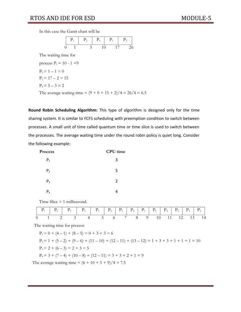
RTOS AND IDE FOR ESD MODULE-5
In this case the Gantt chart will be
P1 P2 P4 P1 P3
0 1 5 10 17 26
The waiting time for
process P1 = 10 - 1 =9
P2 = 1 – 1 = 0
P3 = 17 – 2 = 15
P4 = 5 – 3 = 2
The average waiting time = (9 + 0 + 15 + 2)/4 = 26/4 = 6.5
Round Robin Scheduling Algorithm: This type of algorithm is designed only for the time
sharing system. It is similar to FCFS scheduling with preemption condition to switch between
processes. A small unit of time called quantum time or time slice is used to switch between
the processes. The average waiting time under the round robin policy is quiet long. Consider
the following example:
Process CPU time
P1 3
P2 5
P3 2
P4 4
Time Slice = 1 millisecond.
P1 P2 P3 P4 P1 P2 P3 P4 P1 P2 P4 P2 P4 P2
0 1 2 3 4 5 6 7 8 9 10 11 12 13 14
The waiting time for process
P1 = 0 + (4 – 1) + (8 – 5) = 0 + 3 + 3 = 6
P2 = 1 + (5 – 2) + (9 – 6) + (11 – 10) + (12 – 11) + (13 – 12) = 1 + 3 + 3 + 1 + 1 + 1 = 10
P3 = 2 + (6 – 3) = 2 + 3 = 5
P4 = 3 + (7 – 4) + (10 – 8) + (12 – 11) = 3 + 3 + 2 + 1 = 9
The average waiting time = (6 + 10 + 5 + 9)/4 = 7.5

RTOS AND IDE FOR ESD MODULE-5
Task Communication :
A shared memory is an extra piece of memory that is attached to some address spaces for
their owners to use. As a result, all of these processes share the same memory segment and
have access to it. Consequently, race conditions may occur if memory accesses are not
handled properly. The following figure shows two processes and their address spaces. The
yellow rectangle is a shared memory attached to both address spaces and both process 1 and
process 2 can have access to this shared memory as if the shared memory is part of its own
address space. In some sense, the original address spaces is "extended" by attaching this
shared memory.
RTOS AND IDE FOR ESD MODULE-5
Definition - What does Pipe mean?
A pipe is a method used to pass information from one program process to another. Unlike
other types of inter-process communication, a pipe only offers one-way communication by
passing a parameter or output from one process to another. The information that is passed
through the pipe is held by the system until it can be read by the receiving process. also known
as a FIFO for its behavior.
In computing, a named pipe (also known as a FIFO) is one of the methods for intern- process
communication.
It is an extension to the traditional pipe concept on Unix. A traditional pipe is
“unnamed” and lasts only as long as the process.
A named pipe, however, can last as long as the system is up, beyond the life of the
process. It can be deleted if no longer used.
Usually a named pipe appears as a file, and generally processes attach to it for inter-
process communication. A FIFO file is a special kind of file on the local storage which
allows two or more processes to communicate with each other by reading/writing
to/from this file.
A FIFO special file is entered into the filesystem by calling mkfifo() in C. Once we have
created a FIFO special file in this way, any process can open it for reading or writing, in
the same way as an ordinary file. However, it has to be open at both ends
simultaneously before you can proceed to do any input or output operations on it.
Message passing:
Message passing can be synchronous or asynchronous . Synchronous message
passing systems require the sender and receiver to wait for each other while
transferring the message. In asynchronous communication the sender and
receiver do not wait for each other and can carry on their own computations while
transfer of messages is being done.

RTOS AND IDE FOR ESD MODULE-5
The advantage to synchronous message passing is that it is conceptually less complex.
Synchronous message passing is analogous to a function call in which the message sender is
the function caller and the message receiver is the called function. Function calling is easy
and familiar. Just as the function caller stops until the called function completes, the sending
process stops until the receiving process completes. This alone makes synchronous message
unworkable for some applications. For example, if synchronous message passing would be
used exclusively, large, distributed systems generally would not perform well enough to be
usable. Such large, distributed systems may need to continue to operate while some of their
subsystems are down; subsystems may need to go offline for some kind of maintenance, or
have times when subsystems are not open to receiving input from other systems.
Message queue:
Message queues provide an asynchronous communications protocol, meaning that the
sender and receiver of the message do not need to interact with the message queue at the
same time. Messages placed onto the queue are stored until the recipient retrieves them.
Message queues have implicit or explicit limits on the size of data that may be transmitted in
a single message and the number of messages that may remain outstanding on the queue.
Many implementations of message queues function internally: within an operating system
or within an application. Such queues exist for the purposes of that system
only.[1][2][3]
Other implementations allow the passing of messages between different computer systems,
potentially connecting multiple applications and multiple operating systems.[4] These
message queueing systems typically provide enhanced resilience functionality to ensure that
messages do not get "lost" in the event of a system failure. Examples of commercial
implementations of this kind of message queueing software (also known as message-
oriented middleware) include IBM WebSphere MQ (formerly MQ Series) and Oracle
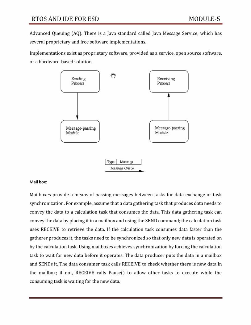
RTOS AND IDE FOR ESD MODULE-5
Advanced Queuing (AQ). There is a Java standard called Java Message Service, which has
several proprietary and free software implementations.
Implementations exist as proprietary software, provided as a service, open source software,
or a hardware-based solution.
Mail box:
Mailboxes provide a means of passing messages between tasks for data exchange or task
synchronization. For example, assume that a data gathering task that produces data needs to
convey the data to a calculation task that consumes the data. This data gathering task can
convey the data by placing it in a mailbox and using the SEND command; the calculation task
uses RECEIVE to retrieve the data. If the calculation task consumes data faster than the
gatherer produces it, the tasks need to be synchronized so that only new data is operated on
by the calculation task. Using mailboxes achieves synchronization by forcing the calculation
task to wait for new data before it operates. The data producer puts the data in a mailbox
and SENDs it. The data consumer task calls RECEIVE to check whether there is new data in
the mailbox; if not, RECEIVE calls Pause() to allow other tasks to execute while the
consuming task is waiting for the new data.

RTOS AND IDE FOR ESD MODULE-5
Signaling :
signals are commonly used in POSIX systems. Signals are sent to the current process telling
it what it needs to do, such as, shutdown, or that it has committed an exception. A process
has several signal-handlers which execute code when a relevant signal is encountered. The
ANSI header for these tasks is <signal.h>, which includes routines to allow signals to be
raised and read.
Signals are essentially software interrupts. It is possible for a process to ignore most signals,
but some cannot be blocked. Some of the common signals are Segmentation Violation
(reading or writing memory that does not belong to this process), Illegal Instruction (trying
to execute something that is not a proper instruction to the CPU), Halt (stop processing for
the moment), Continue (used after a Halt), Terminate (clean up and quit), and Kill (quit now
without cleaning up).
RPC:
Remote Procedure Call (RPC) is a powerful technique for constructing distributed, client-
server based applications. It is based on extending the conventional local procedure
calling, so that the called procedure need not exist in the same address space as the
calling procedure. The two processes may be on the same system, or they may be on
different systems with a network connecting them.

RTOS AND IDE FOR ESD MODULE-5
The following steps take place during a RPC:
1. A client invokes a client stub procedure, passing parameters in the usual way. The client
stub resides within the client’s own address space.
2. The client stub marshalls(pack) the parameters into a message. Marshalling includes
converting the representation of the parameters into a standard format, and copying each
parameter into the message.
3. The client stub passes the message to the transport layer, which sends it to the remote
server machine.
4. On the server, the transport layer passes the message to a server stub, which
demarshalls(unpack) the parameters and calls the desired server routine using the regular
procedure call mechanism.
5. When the server procedure completes, it returns to the server stub (e.g., via a normal
procedure call return), which marshalls the return values into a message. The server stub
then hands the message to the transport layer.
6. The transport layer sends the result message back to the client transport layer, which
hands the message back to the client stub.
7. The client stub demarshalls the return parameters and execution returns to the caller.
Process Synchronization
A co-operation process is one that can affect or be affected by other processes
executing in the system. Co-operating process may either directly share a logical
address space or be allotted to the shared data only through files. This concurrent
access is known as Process synchronization.
Critical Section Problem:
Consider a system consisting of n processes (P0, P1, ………Pn -1) each process has
a segment of code which is known as critical section in which the process may be
changing common variable, updating a table, writing a file and so on. The
important feature of the system is that when the process is executing in its critical
section no other process is to be allowed to execute in its critical section.
RTOS AND IDE FOR ESD MODULE-5
The execution of critical sections by the processes is a mutually exclusive. The
critical section problem is to design a protocol that the process can use to
cooperate each process must request permission to enter its critical section. The
section of code implementing this request is the entry section. The critical section
is followed on exit section. The remaining code is the remainder section.
Example:
While (1)
{
Entry Section;
Critical
Section; Exit
Section;
Remainder Section;
}
A solution to the critical section problem must satisfy the following three conditions.
1. Mutual Exclusion: If process Pi is executing in its critical section then no any
other process can be executing in their critical section.
2. Progress: If no process is executing in its critical section and some
process wish to enter their critical sections then only those process that
are not executing in their remainder section can enter its critical section
next.
3. Bounded waiting: There exists a bound on the number of times that
other processes are allowed to enter their critical sections after a process
has made a request.
Deadlock: In a multiprogramming environment several processes may compete for a finite
number of resources. A process request resources; if the resource is available at
that time a process enters the wait state. Waiting process may never change its
state because the resources requested are held by other waiting process. This
situation is known as deadlock.

RTOS AND IDE FOR ESD MODULE-5
Deadlock Characteristics: In a deadlock process never finish executing and
system resources are tied up. A deadlock situation can arise if the following four
conditions hold simultaneously in a system.
Mutual Exclusion: At a time only one process can use the resources. If
another process requests that resource, requesting process must wait
until the resource has been released.
Hold and wait: A process must be holding at least one resource and
waiting to additional resource that is currently held by other processes.
No Preemption: Resources allocated to a process can’t be forcibly taken
out from it unless it releases that resource after completing the task.
Circular Wait: A set {P0, P1, …….Pn} of waiting state/ process must exists
such that P0 is waiting for a resource that is held by P1, P1 is waiting for
the resource that is held by P2 ….. P(n – 1) is waiting for the resource that
is held by Pn and Pn is waiting for the resources that is held by P4.
Dining Philosopher Problem: Consider 5 philosophers to spend their lives in thinking &
eating. A philosopher shares common circular table surrounded by 5 chairs each occupies
by one philosopher. In the center of the table there is a bowl of rice and the table is laid
with 6 chopsticks as shown in below figure.

RTOS AND IDE FOR ESD MODULE-5
When a philosopher thinks she does not interact with her colleagues. From time to time a
philosopher gets hungry and tries to pickup two chopsticks that are closest to her. A philosopher
may pickup one chopstick or two chopsticks at a time but she cannot pickup a chopstick that is
already in hand of the neighbor. When a hungry philosopher has both her chopsticks at the same
time, she eats without releasing her chopsticks. When she finished eating, she puts down both
of her chopsticks and starts thinking again. This problem is considered as classic synchronization
problem. According to this problem each chopstick is represented by a semaphore. A philosopher
grabs the chopsticks by executing the wait operation on that semaphore. She releases the
chopsticks by executing the signal operation on the appropriate semaphore
The structure of dining philosopher is as follows:
do{
Wait ( chopstick [i]);
Wait (chopstick [(i+1)%5]);
. . . . . . . . . . . . .
Eat
. . . . . . . . . . . . .
Signal (chopstick [i]);
Signal (chopstick [(i+1)%5]);
. . . . . . . . . . . . .
Think
. . . . . . . . . . . . .
} While (1);
RTOS AND IDE FOR ESD MODULE-5
The Integrated Development Environment:
Integrated development environments are designed to maximize programmer productivity
by providing tight-knit components with similar user interfaces. IDEs present a single
program in which all development is done. This program typically provides many features
for authoring, modifying, compiling, deploying and debugging software. This contrasts with
software development using unrelated tools, such as vi, GCC or make.
One aim of the IDE is to reduce the configuration necessary to piece together multiple
development utilities, instead providing the same set of capabilities as a cohesive unit.
Reducing that setup time can increase developer productivity, in cases where learning to use
the IDE is faster than manually integrating all of the individual tools. Tighter integration of
all development tasks has the potential to improve overall productivity beyond just helping
with setup tasks. For example, code can be continuously parsed while it is being edited,
providing instant feedback when syntax errors are introduced. That can speed learning a
new programming language and its associated libraries.
Some IDEs are dedicated to a specific programming language, allowing a feature set that
most closely matches the programming paradigms of the language. However, there are many
multiple-language IDEs, such as Eclipse, ActiveState Komodo, IntelliJ IDEA, Oracle
JDeveloper, NetBeans, Codenvy and Microsoft Visual Studio. Xcode, Xojo and Delphi are
dedicated to a closed language or set of programming languages.
While most modern IDEs are graphical, text-based IDEs such as Turbo Pascal were in popular
use before the widespread availability of windowing systems like Microsoft Windows and
the X Window System (X11). They commonly use function keys or hotkeys to execute
frequently used commands or macros.

RTOS AND IDE FOR ESD MODULE-5
A cross compiler is a compiler capable of creating executable code for a platform other than
the one on which the compiler is running. For example in order to compile for Linux/ARM
you first need to obtain its libraries to compile against.
A cross compiler is necessary to compile for multiple platforms from one machine. A
platform could be infeasible for a compiler to run on, such as for the microcontroller of an
embedded system because those systems contain no operating system. In
paravirtualization one machine runs many operating systems, and a cross compiler could
generate an executable for each of them from one main source.
Cross compilers are not to be confused with a source-to-source compilers. A cross compiler
is for cross-platform software development of binary code, while a source-to- source
"compiler" just translates from one programming language to another in text code. Both are
programming tools.
Uses of cross compilers
The fundamental use of a cross compiler is to separate thebuild environment from target
environment. This is useful in a number of situations:
Embedded computers where a device has extremely limited resources. For example, a
microwave oven will have an extremely small computer to read its touchpad and door
sensor, provide output to a digital display and speaker, and to control the machinery for
cooking food. This computer will not be powerful enough to run a compiler, a file system,
or a development environment. Since debugging and testing may also require more
resources than are available on an embedded system, cross- compilation can be less
involved and less prone to errors than native compilation.
Compiling for multiple machines. For example, a company may wish to support several
different versions of an operating system or to support several different operating systems.
By using a cross compiler, a single build environment can be set up to compile for each of
these targets.
Compiling on a server farm. Similar to compiling for multiple machines, a complicated build
that involves many compile operations can be executed across any machine that is free,
regardless of its underlying hardware or the operating system version that it is running.

RTOS AND IDE FOR ESD MODULE-5
Bootstrapping to a new platform. When developing software for a new platform, or the
emulator of a future platform, one uses a cross compiler to compile necessary tools such as
the operating system and a native compiler.
What is a Disassembler?
In essence, a disassembler is the exact opposite of an assembler. Where an assembler
converts code written in an assembly language into binary machine code, a disassembler
reverses the process and attempts to recreate the assembly code from the binary machine
code.
Since most assembly languages have a one-to-one correspondence with underlying
machine instructions, the process of disassembly is relatively straight-forward, and a basic
disassembler can often be implemented simply by reading in bytes, and performing a table
lookup. Of course, disassembly has its own problems and pitfalls, and they are covered later
in this chapter.
Many disassemblers have the option to output assembly language instructions in Intel,
AT&T, or (occasionally) HLA syntax. Examples in this book will use Intel and AT&T syntax
interchangeably. We will typically not use HLA syntax for code examples, but that may
change in the future.
Decompilers
Decompilers take the process a step further and actually try to reproduce the code in a
high level language. Frequently, this high level language is C, because C is simple and
primitive enough to facilitate the decompilation process. Decompilation does have its
drawbacks, because lots of data and readability constructs are lost during the original
compilation process, and they cannot be reproduced. Since the science of decompilation is
still young, and results are "good" but not "great", this page will limit itself to a listing of
decompilers, and a general (but brief) discussion of the possibilities of decompilation.

RTOS AND IDE FOR ESD MODULE-5
Tools
As with other software, embedded system designers use compilers, assemblers, and
debuggers to develop embedded system software. However, they may also use some more
specific tools:
For systems using digital signal processing, developers may use a math workbench such as
Scilab / Scicos, MATLAB / Simulink, EICASLAB, MathCad, Mathematica,or FlowStone DSP to
simulate the mathematics. They might also use libraries for both the host and target which
eliminates developing DSP routines as done in DSPnano RTOS.
model based development tool like VisSim lets you create and simulate graphical data flow
and UML State chart diagrams of components like digital filters, motor controllers,
communication protocol decoding and multi-rate tasks. Interrupt handlers can also be
created graphically. After simulation, you can automatically generate C-code to the VisSim
RTOS which handles the main control task and preemption of background tasks, as well as
automatic setup and programming of on-chip peripherals.
Debugging
Embedded debugging may be performed at different levels, depending on the facilities
available. From simplest to most sophisticated they can be roughly grouped into the
following areas:
Interactive resident debugging, using the simple shell provided by the embedded operating
system (e.g. Forth and Basic)
External debugging using logging or serial port output to trace operation using either a
monitor in flash or using a debug server like the Remedy Debugger which even works for
heterogeneous multicore systems.
An in-circuit debugger (ICD), a hardware device that connects to the microprocessor via a
JTAG or Nexus interface. This allows the operation
of the microprocessor to be controlled externally, but is typically restricted to specific
debugging capabilities in the processor.

RTOS AND IDE FOR ESD MODULE-5
An in-circuit emulator (ICE) replaces the microprocessor with a simulated equivalent,
providing full control over all aspects of the microprocessor.
A complete emulator provides a simulation of all aspects of the hardware, allowing all of it
to be controlled and modified, and allowing debugging on a normal PC. The downsides are
expense and slow operation, in some cases up to 100X slower than the final system.
For SoC designs, the typical approach is to verify and debug the design on an FPGA
prototype board. Tools such as Certus are used to insert probes in the FPGA RTL that make
signals available for observation. This is used to debug hardware, firmware and software
interactions across multiple FPGA with capabilities similar to a logic analyzer.
Unless restricted to external debugging, the programmer can typically load and run
software through the tools, view the code running in the processor, and start or stop its
operation. The view of the code may be as HLL source-code, assembly code or mixture of
both.
Simulation is the imitation of the operation of a real-world process or system over time.[1]
The act of simulating something first requires that a model be developed; this model
represents the key characteristics or behaviors/functions of the selected physical or abstract
system or process. The model represents the system itself, whereas the simulation
represents the operation of the system over time.
Simulation is used in many contexts, such as simulation of technology for performance
optimization, safety engineering, testing, training, education, and video games. Often,
computer experiments are used to study simulation models.
Key issues in simulation include acquisition of valid source information about the relevant
selection of key characteristics and behaviours, the use of simplifying approximations and
assumptions within the simulation, and fidelity and validity of the simulation outcomes.

RTOS AND IDE FOR ESD MODULE-5
Emulator
This article is about emulators in computing. For a line of digital musical instruments, see
E-mu Emulator. For the Transformers character, see Circuit Breaker
(Transformers).#Shattered Glass. For other uses, see Emulation (disambiguation).
DOSBox emulates the command-line interface of DOS.
In computing, an emulator is hardware or software or both that duplicates (or emulates)
the functions of one computer system (the guest) in another computer system (the host),
different from the first one, so that the emulated behavior closely resembles the behavior
of the real system (the guest).
The above described focus on exact reproduction of behavior is in contrast to some other
forms of computer simulation, in which an abstract model of a system is being simulated.
For example, a computer simulation of a hurricane or a chemical reaction is not emulation.
OUT-OF-CIRCUIT :The code to be run on the target embedded system is always developed
on the host computer. This code is called the binary executable image or simply hex code.
The process of putting this code in the memory chip of the target embedded system is called
Downloading.
RTOS AND IDE FOR ESD MODULE-5
There are two ways of downloading the binary image on the embedded system:
1. Using a Device Programmer
A device programmer is a piece of hardware that works in two steps.
Step 1 Once the binary image is ready on the computer, the device programmer is
connected to the computer and the binary image is transferred to the device programmer.
Step 2 The microcontroller/microprocessor or memory chip, usually the ROM which is
supposed to contain the binary image is placed on the proper socket on the device
programmer. The device programmer contains a software interface through which the user
selects the target microprocessor for which the binary image has to be downloaded. The
Device programmer then transfers the binary image bit by bit to the chip.
2. Using In System Programmer(ISP)
Certain Target embedded platforms contain a piece of hardware called ISP that have a
hardware interface to both the computer as well the chip where the code is to be
downloaded.
The user through the ISP’s software interface sends the binary image to the target board.
This avoids the requirement of frequently removing the microprocessor / microcontroller
or ROM for downloading the code if a device programmer had to be used.
DEBUGGING THE EMBEDDED SOFTWARE
Debugging is the process of eliminating the bugs/errors in software.
The software written to run on embedded systems may contain errors and hence
needs debugging.
However, the difficulty in case of embedded systems is to find out the bug/ error itself.
This is because the binary image you downloaded on the target board was free of
syntax errors but

RTOS AND IDE FOR ESD MODULE-5
still if the embedded system does not function the way it was supposed to be then it can be
either because of a hardware problem or a software problem. Assuming that the hardware
is perfect all that remains to check is the software.
The difficult part here is that once the embedded system starts functioning there is
no way for the user or programmer to know the internal state of the components on
the target board.
The most primitive method of debugging is using LEDs. This is similar to using a printf
or a cout statement in c/c++ programs to test if the control enters the loop or not.
Similarly an LED blind or a pattern of LED blinks can be used to check if the control
enters a particular piece of code.
There are other advanced debugging tools like;
a. Remote debugger
b. Emulator
c. Simulator
Remote Debuggers
Remote Debugger is a tool that can be commonly used for:
Downloading
Executing and
Debugging embedded software
A Remote Debugger contains a hardware interface between the host computer and
the target embedded system.