electronics club - students' gymkhana - iit kanpur
TRANSCRIPT
Electronics Club
Verilog Lecture Series IIT KANPUR
Pre-requisite
• Basics of any programming language
• Easy for those with some programming experience
• Some background in digital logic will also be helpful
Need
• Execute different code blocks simultaneously as opposed to sequential execution of most programming languages.
• Make circuits easier to verify and reduces error

Let’s Get Started
Terminology
• Verilog: Hardware Description Language (HDL)
• Used to model electronic systems
• Modules :- “ Black Boxes ”
• Ports :- input , output , inout
• Case Sensitive
• Synthesis
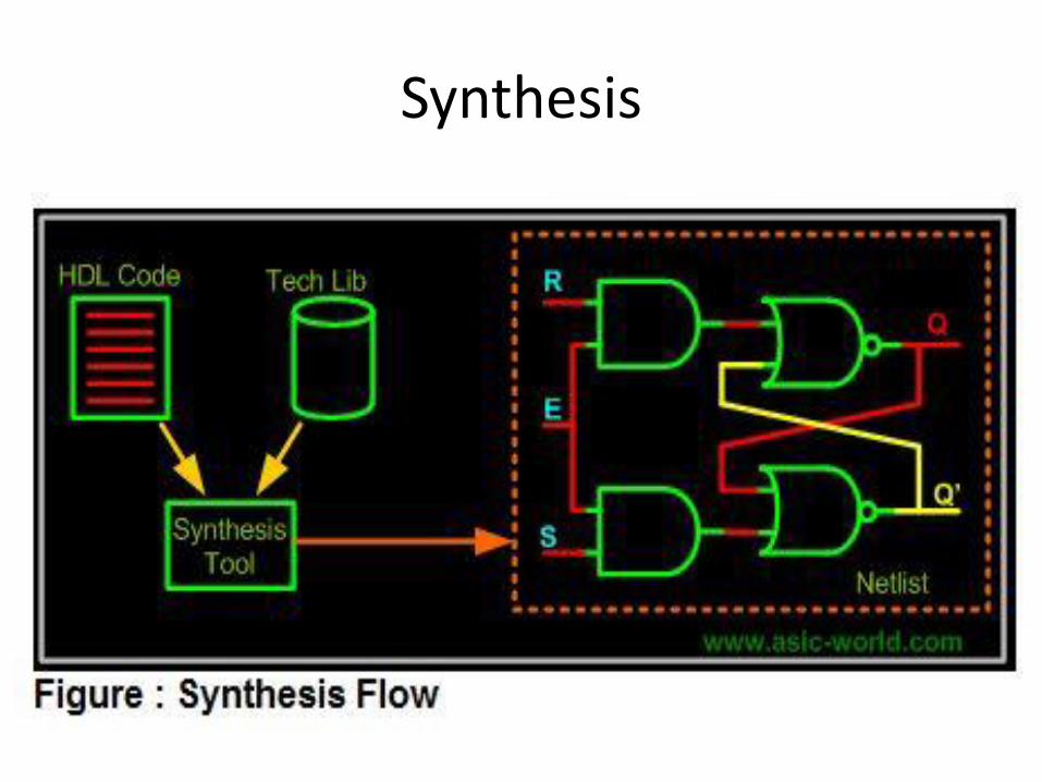
Synthesis
Drivers
• A driver is a data type which can drive a load.
• Basically, in a physical circuit, a driver would be anything that electrons can move through
• Two types of Drivers

• The first type of driver – one that can store a value example flipflop.
• It is called a “reg” in Verilog (short for "register")
• The second data type is one can not store value, but connects two points e.g. wire.
• It is called a “wire”
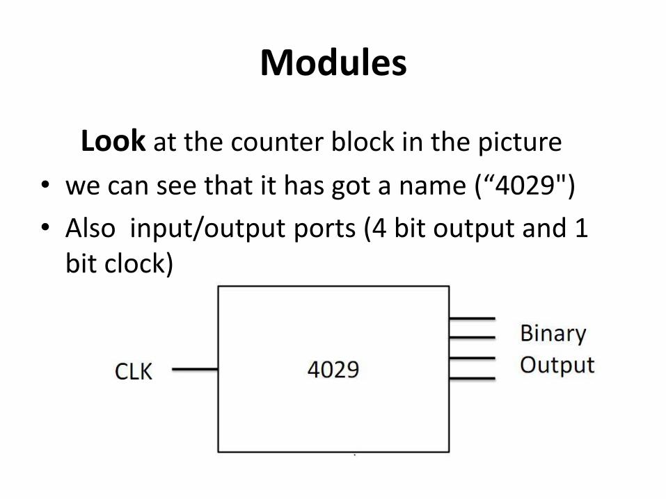
Modules
Look at the counter block in the picture
• we can see that it has got a name (“4029")
• Also input/output ports (4 bit output and 1 bit clock)
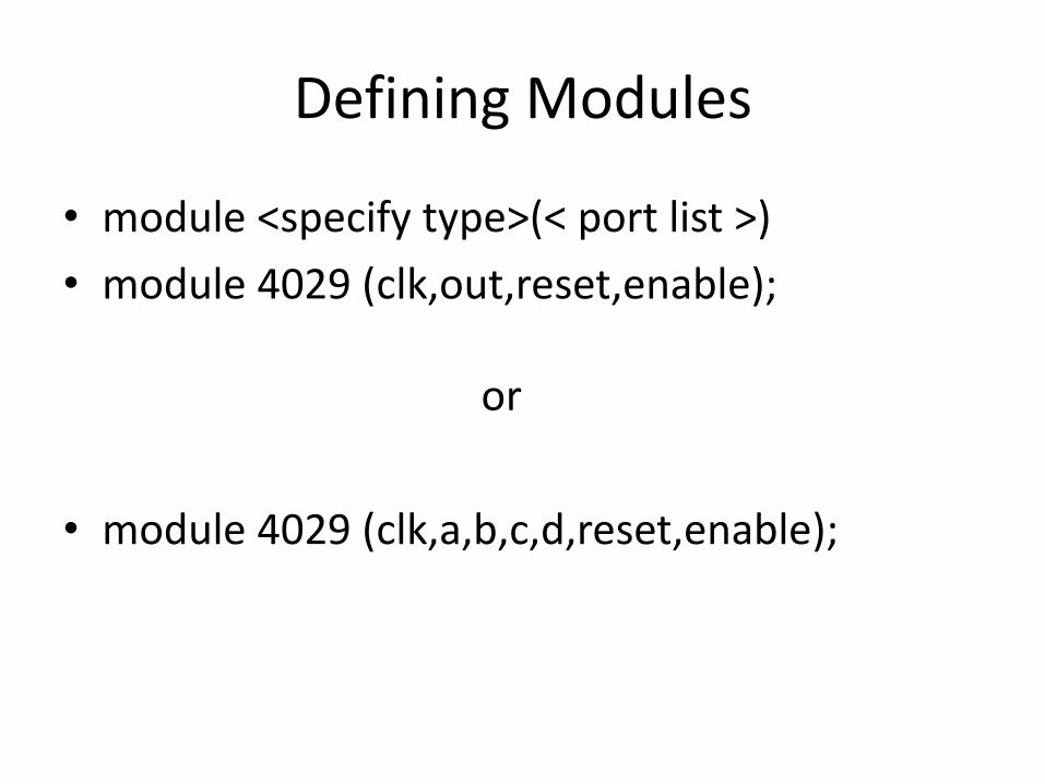
Defining Modules
• module <specify type>(< port list >)
• module 4029 (clk,out,reset,enable); or
• module 4029 (clk,a,b,c,d,reset,enable);

Input and ouput
input clk; input clk;
input reset; or input reset;
input enable; input enable;
output a,b,c,d; output [3:0] out;
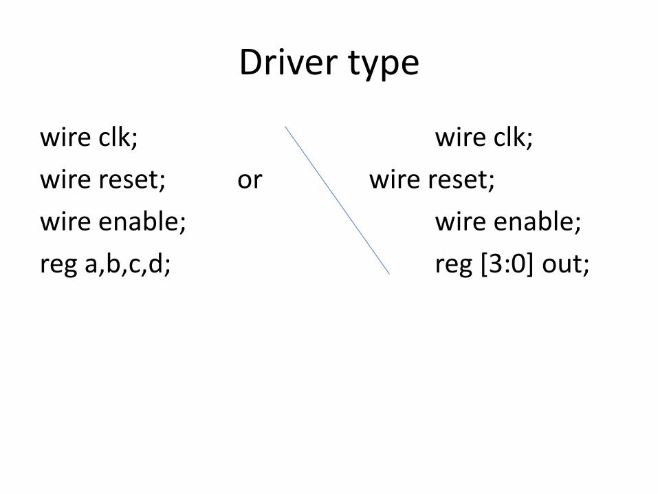
Driver type
wire clk; wire clk;
wire reset; or wire reset;
wire enable; wire enable;
reg a,b,c,d; reg [3:0] out;
Summary
• We learnt how a block/module is defined in Verilog.
• We learnt how to define ports and port directions.
• We learnt how to declare vector/scalar ports.
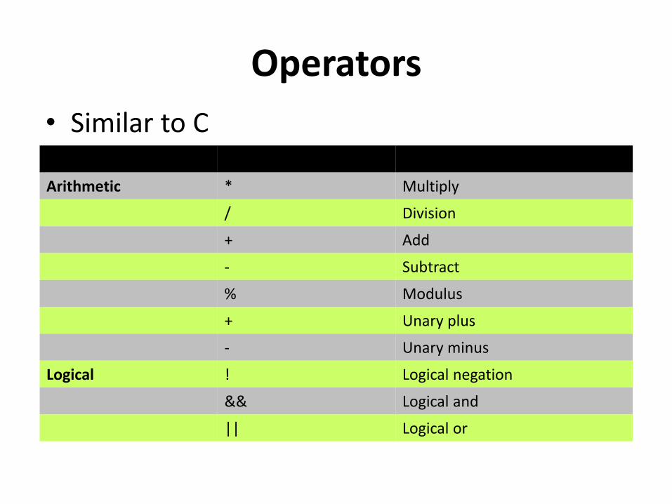
Operators
• Similar to C
Operator Type Operator Symbol Operation Performed
Arithmetic * Multiply
/ Division
+ Add
- Subtract
% Modulus
+ Unary plus
- Unary minus
Logical ! Logical negation
&& Logical and
|| Logical or
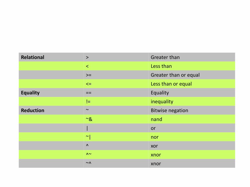
Relational > Greater than
< Less than
>= Greater than or equal
<= Less than or equal
Equality == Equality
!= inequality
Reduction ~ Bitwise negation
~& nand
| or
~| nor
^ xor
^~ xnor
~^ xnor
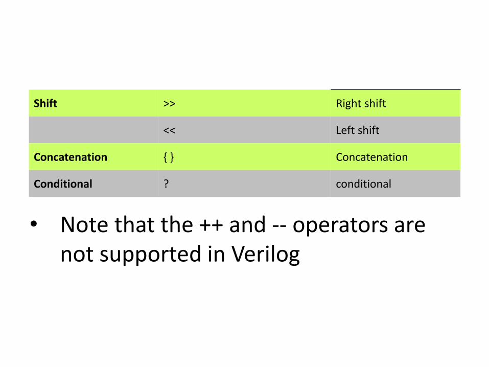
• Note that the ++ and -- operators are not supported in Verilog
Shift >> Right shift
<< Left shift
Concatenation { } Concatenation
Conditional ? conditional
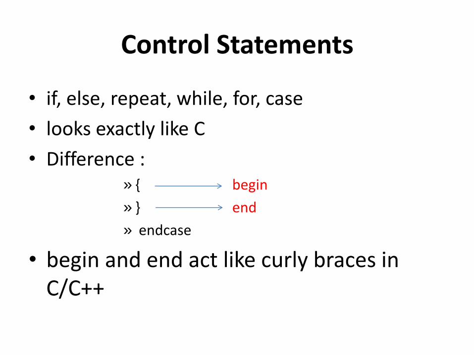
Control Statements
• if, else, repeat, while, for, case
• looks exactly like C
• Difference : » { begin
» } end
» endcase
• begin and end act like curly braces in C/C++
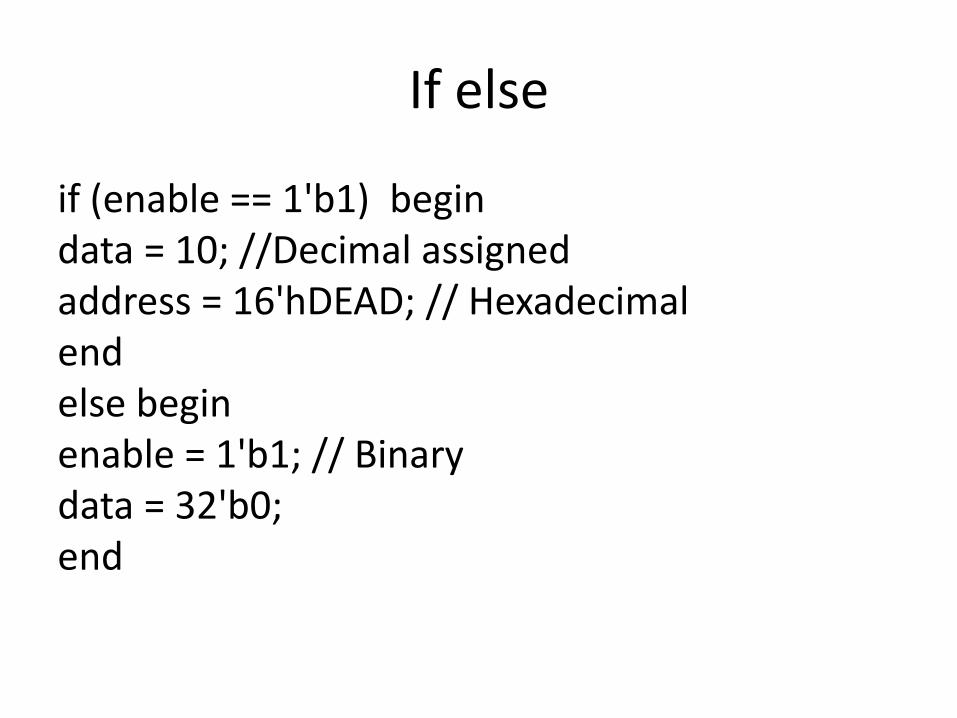
If else
if (enable == 1'b1) begin data = 10; //Decimal assigned address = 16'hDEAD; // Hexadecimal end else begin enable = 1'b1; // Binary data = 32'b0; end
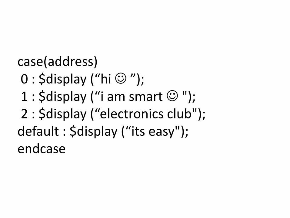
case(address) 0 : $display (“hi ”); 1 : $display (“i am smart "); 2 : $display (“electronics club"); default : $display (“its easy"); endcase
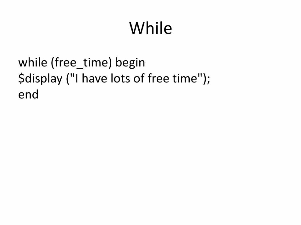
While
while (free_time) begin $display ("I have lots of free time"); end

What’s New Then ???
• Always Block
• Initial Block
• Assign
• Blocking vs Non-Blocking

Always
• Always block
• All blocks marked always will run simultaneously
• You can have two or more always blocks in a program going at the same time
• The @ symbol after reserved word ' always', indicates that the block will be triggered "at" the condition in parenthesis after symbol @
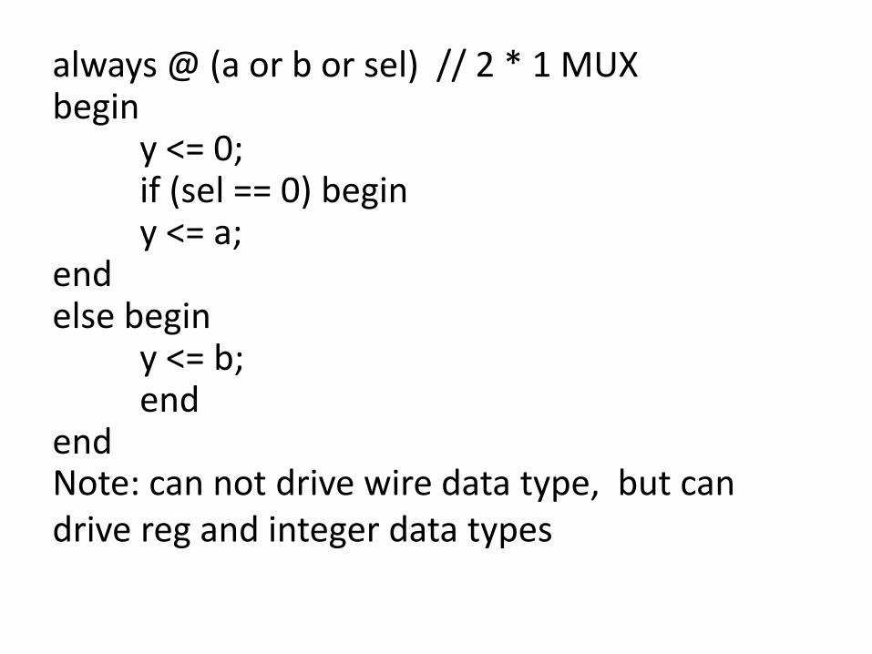
Note: can not drive wire data type, but can drive reg and integer data types
always @ (a or b or sel) // 2 * 1 MUX begin y <= 0; if (sel == 0) begin y <= a; end else begin y <= b; end end
Initial Block
• An initial block is executed only once when simulation starts
• This is useful in writing test benches
• If we have multiple initial blocks, then all of them are executed at the beginning of simulation
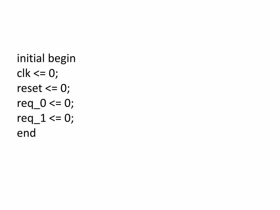
initial begin clk <= 0; reset <= 0; req_0 <= 0; req_1 <= 0; end
Summary
• While, if-else, case(switch) statements are the same as in C language
• If-else and case statements require all the cases to be covered for combinational logic
• For-loop is the same as in C, but no ++ and -- operators
Program
• Gates
• Counter
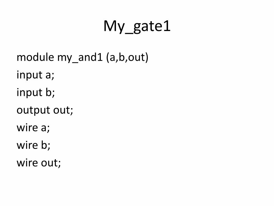
My_gate1
module my_and1 (a,b,out)
input a;
input b;
output out;
wire a;
wire b;
wire out;

My_and2
module my_and2 (a,b,out)
input [4:0] a;
input [4:0] b;
output [4:0] out;
wire [4:0] a;
wire [4:0] b;
wire [4:0] out;
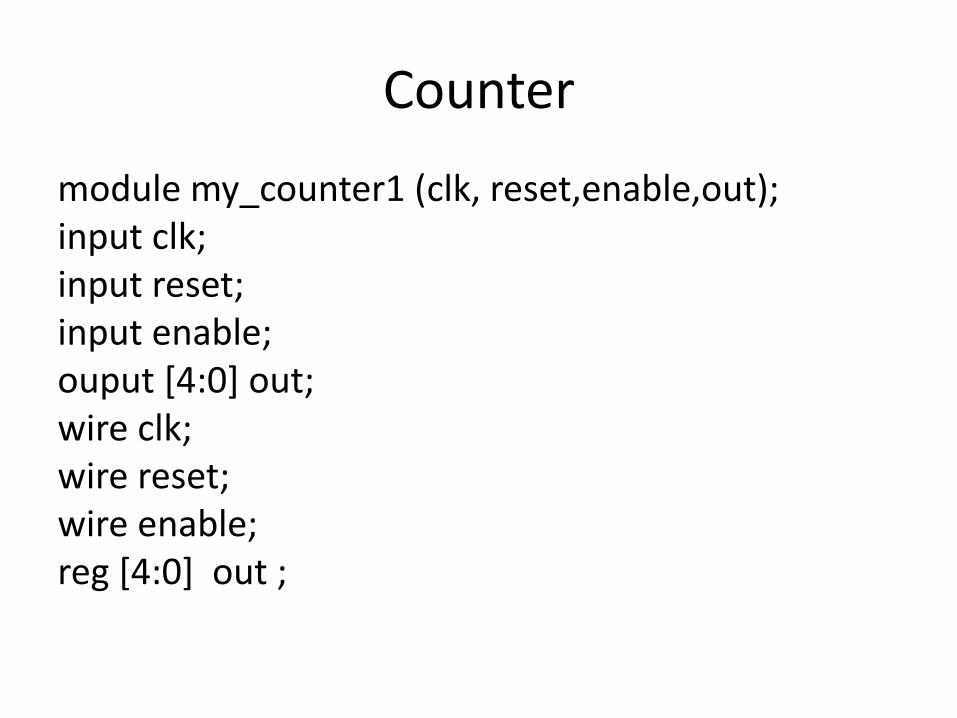
Counter
module my_counter1 (clk, reset,enable,out); input clk; input reset; input enable; ouput [4:0] out; wire clk; wire reset; wire enable; reg [4:0] out ;
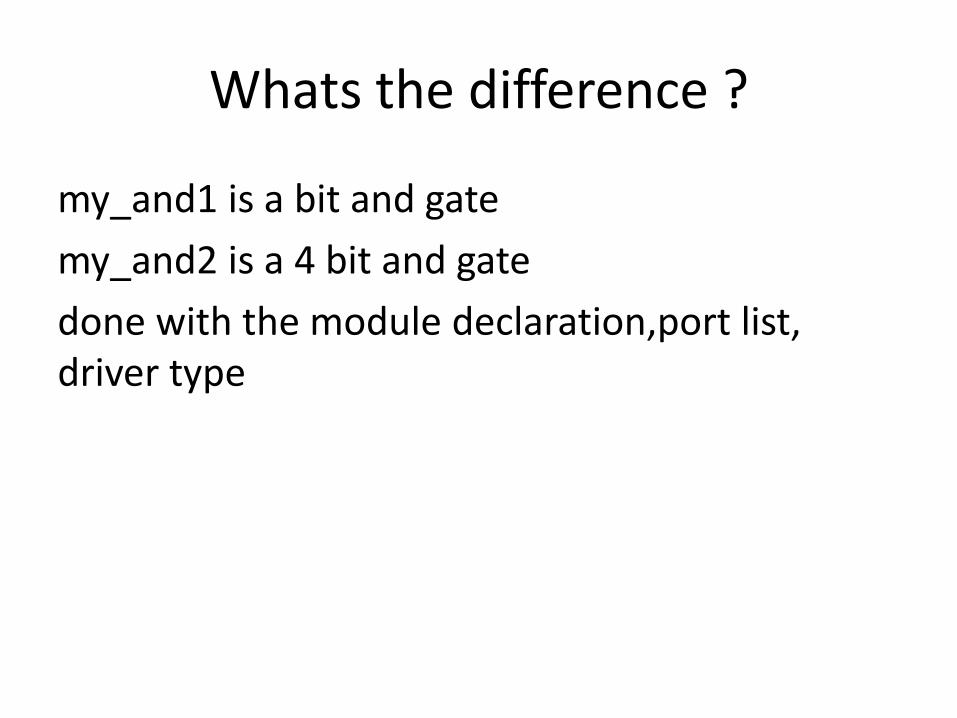
Whats the difference ?
my_and1 is a bit and gate
my_and2 is a 4 bit and gate
done with the module declaration,port list, driver type
