electronics - ministry of education · electronics for our upper secondary school curriculum. the...
TRANSCRIPT
1
ELECTRONICS SYLLABUS
Upper Secondary Express Course
Implementation starting with 2017 Secondary Three Cohort
© 2016 Curriculum Planning and Development Division. This publication is not for sale. All rights reserved. No part of this publication may be reproduced without the prior permission of the Ministry of Education, Singapore.
2
CONTENTS
Page
1. INTRODUCTION
Desired Outcomes of Education and Learning of Electronics
Value of Electronics in the O-Level Curriculum
Engineering Design Process in Electronic Engineering
Design Intent of Syllabus – The Systems Approach
Electronics Curriculum Framework
Aims of Syllabus
21st Century Competencies (21CC) in Electronics Curriculum
4 4 5 6 7 8 9
2. CONTENT
Overview of the Content Structure
18
3. PEDAGOGY
Alignment with Principals of Applied Learning
Attaining Goals of Syllabus
Authenticity of Learning Experiences
Teaching & Learning Strategies
36 36 36 37
4. ASSESSMENT
Assessment for Learning in Electronics
The O-Level Examination for Electronics
40 41
3
SECTION 1: INTRODUCTION
Desired Outcomes of Education and Learning of Electronics
Value of Electronics in O-Level Curriculum Engineering Design Process in Electronic Engineering
Design Intent of Syllabus – The Systems Approach Electronics Curriculum Framework
Aims of Syllabus 21st Century Competencies in Electronics Curriculum

4
1. INTRODUCTION
Desired Outcomes of Education and Learning of Electronics The Desired Outcomes of Education (DOE) are attributes that educators aspire for every Singaporean to have by the completion of his formal education. These outcomes establish a common purpose for educators, drive our policies and programmes, and allow us to determine how well our education system is doing. The person who is schooled in the Singapore Education system embodies the DOE. He has a good sense of self-awareness, a sound moral compass, and the necessary skills and knowledge to take on challenges of the future. He is responsible to his family, community and nation. He appreciates the beauty of the world around him, possesses a healthy mind and body, and has a zest for life. In sum, he is
a confident person who has a strong sense of right and wrong, is adaptable and resilient, knows himself, is discerning in judgment, thinks independently and critically, and communicates effectively;
a self-directed learner who takes responsibility for his own learning, who questions, reflects and perseveres in the pursuit of learning;
an active contributor who is able to work effectively in teams, exercises initiative, takes calculated risks, is innovative and strives for excellence; and,
a concerned citizen who is rooted to Singapore, has a strong civic consciousness, is informed, and takes an active role in bettering the lives of others around him.
The learning of Electronics is aligned with the DOE. Through the application of scientific knowledge on electricity and electronics, students solve authentic engineering problems using the engineering design process. In the design phase of the process, students need to carefully consider the requirements and weigh the pros and cons of different possible designs before deciding on the optimal one. In the build and test phases, students realise the design by building a prototype of an electronic system and testing it to verify if it works as designed. In many instances, troubleshooting needs to be performed to identify and remedy faults before the prototype becomes fully functional. These authentic engineering experiences encourage students to be innovative, take calculated risks and persevere to reach a workable solution. Besides developing this 'can-do' attitude, there are opportunities for students to think critically, evaluate information and communicate effectively. Students will also see how designing solutions to solve practical problems can improve the lives of people around them. The Electronics syllabus thus realises important aspects of the DOE by developing students useful and transferrable attributes, knowledge and skills related to engineering. Value of Electronics in the O-Level Curriculum Learning electronics allows students to gain insights into the working of electronic devices encountered in daily lives, enabling them to better appreciate technological advancements and

5
benefits that the field of electronics has brought about. As a prominent field of engineering, electronics also has the potential to provide a wide range of authentic contexts to develop engineering skills and dispositions. An electronic student will experience the engineering design process during the course of study and develop engineering skills such as troubleshooting, systems thinking and problem solving skills in the learning process.
Troubleshooting and Problem Solving skills
In engineering, troubleshooting is a logical and systematic search for the source of a problem and usually involves the process of elimination for a workable solution to be generated. Troubleshooting demands students to think critically and apply relevant knowledge to identify and correct the problem. It is a form of problem solving that requires skills such as predicting, making hypothesis, eliminating, generating possibilities, observing, using test equipment, comparing, analysing, evaluating, inferring and verifying.
Systems Thinking and Problem Solving Skills
Systems thinking is the process of understanding how systems 1 behave, interact with their environment and influence each other. However, it is also a term that has different meanings for different fields and disciplines2. In electronics, systems thinking is defined as the ability to (i) understand the parts of a system, their interactions and resulting outputs3; and (ii) explain the role of a system in a larger system of which it is a part4. Problem solving is an application of systems thinking where problems are viewed as having effects on different parts of a system. This problem solving process is particularly useful to solve open-ended and complex engineering problems that have multiple possible solutions. By adopting the systems approach as a way of thinking, students learn to recognize essential interconnections in the technological world and appreciate that systems depend both on the behaviour of individual sub-systems and interactions between the sub-systems.
These skills also support the development of 21CC in the domain of Critical and Inventive Thinking (CIT); and Communication, Collaboration and Information Skills (CCI) (see section on 21st Century Competencies (21CC) in Electronics Curriculum for details).
Engineering Design Process in Electronic Engineering As engineering is commonly described as the applications of scientific knowledge, engineering and science are often compared with each other, e.g. The Next Generation Science Standard 5 differentiates the goal of science and engineering respectively as:
1 Systems are defined by placing boundaries around inter-related parts to make them easier to study. There are systems in nature as well as man-made systems. 2 http://scholar.lib.vt.edu/ejournals/JTE/v24n2/lammi.html 3 Katehi,L., Pearson, G., & Feder, M. (Eds). (2009). Engineering in K-12 education: Understanding the status and improving the prospects. Washington, DC: The National Academies Press. 4 Pourdehnad, John., et.al. (2011). Systems & Design Thinking: A Conceptual Framework for their Integration. Presented at the International Society for the Systems Sciences (ISSS) 55th Annual Conference, “All Together Now: Working Across Disciplines” at University of Hull, Hull, UK, July 17-22. 5 NGSS lead States. (2013). Next Generation Science Standards. Washington, DC: National Academies Press. Available at http://www.nextgenscience.org/next-generation-science-standards
6
“The goal of science is the construction of theories that provide explanatory accounts of the world. A theory becomes accepted when it has multiple lines of empirical evidence and greater explanatory power of phenomena than previous theories.” (NRC Framework, 2012, p. 52)6 “In engineering, the goal is a design rather than an explanation. The process of developing a design is iterative and systematic, as is the process of developing an explanation or a theory in science. Engineers’ activities, however, have elements that are distinct from those of scientists. These elements include specifying constraints and criteria for desired qualities of the solution, developing a design plan, producing and testing models or prototypes, selecting among alternative design features to optimize the achievement of design criteria, and refining design ideas based on the performance of a prototype or simulation.” (NRC Framework, 2012, p. 68-69) Despite the difference in the goals of science and engineering, both are closely related and share many similarities such as “the use of mathematics, the interplay of creativity and logic, the eagerness to be original and public responsibilities”. “Many scientists are doing work that could be described as engineering as well as science. Similarly, many engineers are engaged in science.” The series of steps that scientists take to develop an explanation is often called the scientific method which includes asking questions, constructing a hypothesis, testing the hypothesis by performing experiments, analysis of evidence, drawing of conclusion and communication of results. The series of steps that engineers take to develop a solution to a problem is commonly called the engineering design process which includes specifying requirements, performing research, generating and evaluating different designs, building and testing prototypes and communicating results. Thus, electronic engineering involves the application of the science of electronics to solve problems through the engineering design process. It is an endeavour that drives the rapid development of information and communication technology which has revolutionised the way we live, work and play. Design Intent of Syllabus – The Systems Approach The design of the electronics curriculum took into consideration the key findings from the environment scans of local and international electronics syllabuses, and the value proposition of electronics for our upper secondary school curriculum. The core electronics content is organized as part of systems; and actively involves students in application of knowledge, and the design and testing of electronic systems. The following big ideas are presented in the Electronics curriculum to tie the concepts, skills and processes as a coherent whole:
An electronic system is made up of different components connected as a circuit to achieve intended outcome(s).
An electronic system receives input, processes the input and sends output into the wider environment or another system.
6 National Research Council. (2012). A framework for K–12 science education: Practices, cross-cutting concepts and core ideas. Washington, DC: National Academies Press.
7
Electronic systems are commonly represented by block diagrams and circuit diagrams, while circuit theories are used to understand and analyze electronic circuits
The engineering design process is used to design, build and test an electronic system. Different possible designs need to be investigated and evaluated to select the optimal solution to a problem.
Electronic systems seldom work perfectly when they are first built. Troubleshooting is needed to identify and correct sources of problems.
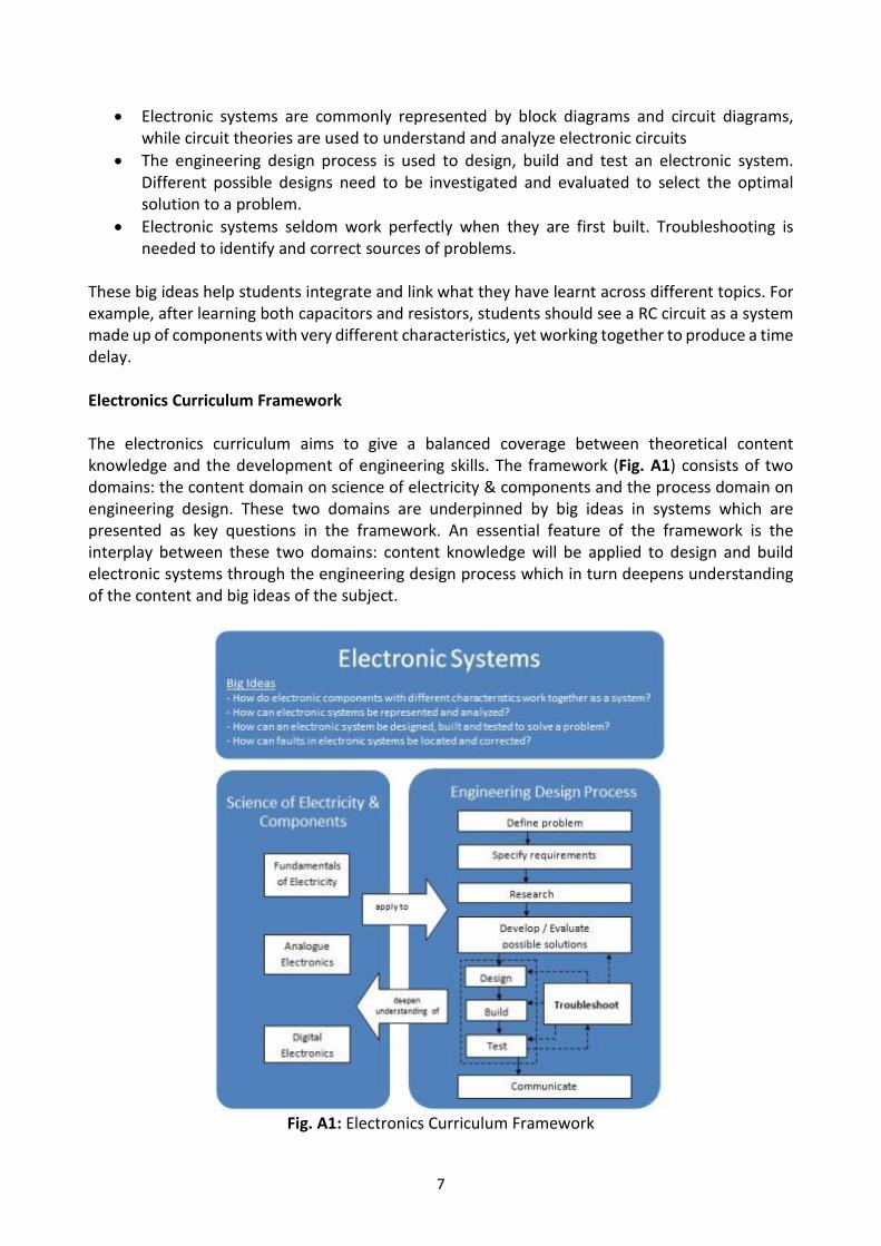
These big ideas help students integrate and link what they have learnt across different topics. For example, after learning both capacitors and resistors, students should see a RC circuit as a system made up of components with very different characteristics, yet working together to produce a time delay. Electronics Curriculum Framework The electronics curriculum aims to give a balanced coverage between theoretical content knowledge and the development of engineering skills. The framework (Fig. A1) consists of two domains: the content domain on science of electricity & components and the process domain on engineering design. These two domains are underpinned by big ideas in systems which are presented as key questions in the framework. An essential feature of the framework is the interplay between these two domains: content knowledge will be applied to design and build electronic systems through the engineering design process which in turn deepens understanding of the content and big ideas of the subject.
Fig. A1: Electronics Curriculum Framework
8
Content Knowledge – Science of Electricity & Components
The content is broadly classified into (i) Fundamentals of Electricity, (ii) Analogue Electronics and (iii) Digital Electronics. The concepts under Fundamentals of Electricity include principles of electricity (e.g. Ohm’s Law), circuit theories (e.g. voltage divider) and basic electrical components (e.g. capacitor). These concepts are needed to analyse, understand and design electrical circuits. Under Analogue Electronics, the operation and use of the two main semiconductor devices, diode and transistor, are covered. The coverage of Digital Electronics includes basic understanding of digital signals, basic logic gates, digital latch and the use of integrated circuits.
Skills Development - Engineering Design Process The engineering design process is a series of systematic steps that engineers use to develop solution to engineering problems (see Table A1 for detailed explanation). Students will understand what each step entails and be equipped with the necessary skills needed to carry out the process correctly and effectively. Example of these skills includes:
project planning
problem analysis
specifying requirements
using block diagram to represent electronic systems
conducting research
evaluating research findings
reading datasheets
drawing circuit diagrams
circuit simulation
evaluating circuit designs
circuit building
troubleshooting
developing tests for circuits
using test equipment
report writing
Both content knowledge and skills development are intricately linked, where content knowledge is applied to solve practical problems using the engineering design process. In the process of implementing the solution in the form of electronic circuits, students will in turn develop a deeper understanding of the content knowledge. Aims of Syllabus
The Electronics curriculum provides students with an understanding of the fundamental working of electronic components and systems, as well as the engineering design process. The syllabus focuses on the application of the knowledge of science of electricity and electronic components to design and build electronics systems that can solve daily problems. The students will also develop testing and troubleshooting skills. Through these learning experiences, the subject should provide a broad-base foundation for further studies in electronics engineering and related field. Specifically, the aims of the syllabus are to:

9
(i) develop attitudes relevant to engineering such as perseverance; curiosity; integrity; striving for accuracy; open-mindedness; inventiveness; problem-solving (“can do” attitude); intellectual thoroughness
(ii) develop abilities and skills related to the engineering design process such as
• systems thinking
• design, build and test electronic systems; and
• troubleshooting
(iii) acquire knowledge of the fundamentals of electronics (iv) develop an appreciation about the usefulness of electronics and its impact on modern society
(v) foster an interest and passion in the engineering field
(vi) inculcate a strong sense of safety and develop safe working habits 21st Century Competencies (21CC) in Electronics Curriculum The Electronics curriculum supports students’ development of important competencies necessary for them to thrive in the 21st century that are anchored in enduring values. The framework for the 21CC and student outcomes is presented in Fig. A2.
Fig. A2: Framework for 21CC and Student Outcomes

10
At the heart of the framework are Core Values that underpin the learning. These values (respect, responsibility, resilience, integrity, care and harmony) define a person’s character and shape beliefs, attitudes and actions of a person.
The middle ring signifies the Social and Emotional Competencies – skills necessary for children to recognise (self-awareness) and manage (self-management) their emotions, develop care and concern for others (social awareness), make responsible decisions (responsible decision-making), establish positive relationships, as well as to handle challenging situations effectively (relationship management).
The outer ring of the framework represents the 21st Century Competencies necessary for the globalised world we live in. These are: Civic Literacy, Global Awareness and Cross-Cultural Skills; Critical and Inventive Thinking; and Communication, Collaboration and Information skills.
Electronics is well-positioned to develop 21CC, especially when solving an engineering problem using the engineering design process. For example, as students analyse and break down a complex engineering problem into manageable tasks, they develop critical and inventive thinking. They will also have opportunities to work collaboratively to discuss and evaluate ideas and research findings, and to present and defend their choice of design. Tapping on the opportunities afforded by the process, the development of 21CC in the areas of “Communication, Collaboration and Information” and “Critical and Inventive Thinking”, is a natural fit. In addition, the ‘design, build and test’ process fosters character-building traits such as creativity, curiosity, open-mindedness and persistence. These are illustrated in Table A2.
11
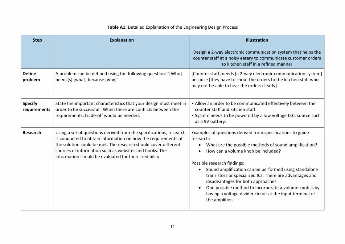
Table A1: Detailed Explanation of the Engineering Design Process
Step Explanation Illustration
Design a 2-way electronic communication system that helps the counter staff at a noisy eatery to communicate customer orders
to kitchen staff in a refined manner
Define problem
A problem can be defined using the following question: “[Who] needs(s) [what] because [why]”
[Counter staff] needs [a 2-way electronic communication system] because [they have to shout the orders to the kitchen staff who may not be able to hear the orders clearly].
Specify requirements
State the important characteristics that your design must meet in order to be successful. When there are conflicts between the requirements, trade-off would be needed.
• Allow an order to be communicated effectively between the counter staff and kitchen staff.
• System needs to be powered by a low voltage D.C. source such as a 9V battery.
Research Using a set of questions derived from the specifications, research is conducted to obtain information on how the requirements of the solution could be met. The research should cover different sources of information such as websites and books. The information should be evaluated for their credibility.
Examples of questions derived from specifications to guide research:
What are the possible methods of sound amplification?
How can a volume knob be included? Possible research findings:
Sound amplification can be performed using standalone transistors or specialized ICs. There are advantages and disadvantages for both approaches.
One possible method to incorporate a volume knob is by having a voltage divider circuit at the input terminal of the amplifier.
12
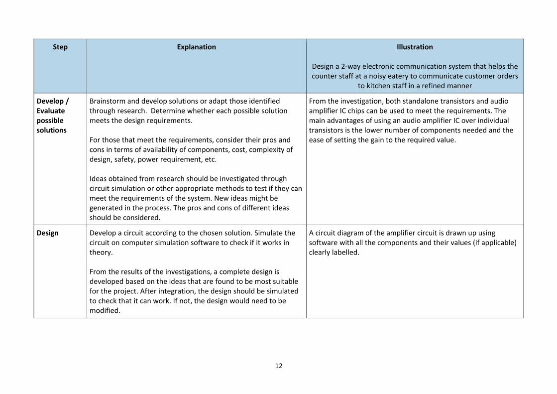
Step Explanation Illustration
Design a 2-way electronic communication system that helps the counter staff at a noisy eatery to communicate customer orders
to kitchen staff in a refined manner
Develop / Evaluate possible solutions
Brainstorm and develop solutions or adapt those identified through research. Determine whether each possible solution meets the design requirements. For those that meet the requirements, consider their pros and cons in terms of availability of components, cost, complexity of design, safety, power requirement, etc. Ideas obtained from research should be investigated through circuit simulation or other appropriate methods to test if they can meet the requirements of the system. New ideas might be generated in the process. The pros and cons of different ideas should be considered.
From the investigation, both standalone transistors and audio amplifier IC chips can be used to meet the requirements. The main advantages of using an audio amplifier IC over individual transistors is the lower number of components needed and the ease of setting the gain to the required value.
Design Develop a circuit according to the chosen solution. Simulate the circuit on computer simulation software to check if it works in theory. From the results of the investigations, a complete design is developed based on the ideas that are found to be most suitable for the project. After integration, the design should be simulated to check that it can work. If not, the design would need to be modified.
A circuit diagram of the amplifier circuit is drawn up using software with all the components and their values (if applicable) clearly labelled.

13
Step Explanation Illustration
Design a 2-way electronic communication system that helps the counter staff at a noisy eatery to communicate customer orders
to kitchen staff in a refined manner
Build Once the circuit is proven to work through circuit simulation, the next step would be to build a prototype (an operating version of a solution) on prototype boards. The prototype should be built using proper techniques to ensure firm electrical connections. The test points should be clearly labelled to facilitate testing. During building, the design might need to be modified if certain components were not available or found to be unsuitable.
The main test points are the input and output terminals of the amplifier. These points should be clearly labelled as well as other test points.
Test Using test equipment, measure and compare the output(s) of the prototype circuit against the requirements. All measurements should be recorded for future reference. If the test shows that the prototype circuit could not meet the requirements, the design might need to be modified.
Using a function generator, produce a sine signal to act as input to the amplifier. Using an oscilloscope, observe the output signal to see if it is one with bigger amplitude. Conduct a field test in a noisy environment to see if the message can be passed on clearly.
Troubleshoot Troubleshooting is a logical and systematic search for the source of a problem and usually involves the process of elimination for a workable solution to be generated. Troubleshooting usually involves two key stages, namely: (i) hypothesis generation to identify one or more potential faults; and (ii) hypothesis evaluation where potential faults are tested and corrected
There is no output signal from the amplifier. The following steps were taken to troubleshoot the problem:
The power supply to the amplifier circuit is checked and found to be ok.
After replacing the transistor with a new one, there is an output signal. This confirmed that the cause of the fault was a damaged transistor.
Communicate Communicate the final solution and processes in the form of a report.
A clear report on the work carried out is produced.
14
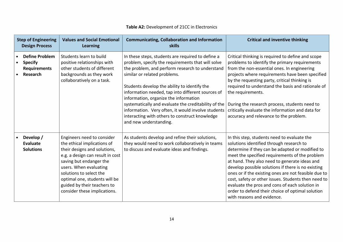
Table A2: Development of 21CC in Electronics
Step of Engineering Design Process
Values and Social Emotional Learning
Communicating, Collaboration and Information skills
Critical and inventive thinking
• Define Problem
• Specify Requirements
• Research
Students learn to build positive relationships with other students of different backgrounds as they work collaboratively on a task.
In these steps, students are required to define a problem, specify the requirements that will solve the problem, and perform research to understand similar or related problems. Students develop the ability to identify the information needed, tap into different sources of information, organize the information systematically and evaluate the creditability of the information. Very often, it would involve students interacting with others to construct knowledge and new understanding.
Critical thinking is required to define and scope problems to identify the primary requirements from the non-essential ones. In engineering projects where requirements have been specified by the requesting party, critical thinking is required to understand the basis and rationale of the requirements. During the research process, students need to critically evaluate the information and data for accuracy and relevance to the problem.
• Develop / Evaluate Solutions
Engineers need to consider the ethical implications of their designs and solutions, e.g. a design can result in cost saving but endanger the users. When evaluating solutions to select the optimal one, students will be guided by their teachers to consider these implications.
As students develop and refine their solutions, they would need to work collaboratively in teams to discuss and evaluate ideas and findings.
In this step, students need to evaluate the solutions identified through research to determine if they can be adapted or modified to meet the specified requirements of the problem at hand. They also need to generate ideas and develop possible solutions if there is no existing ones or if the existing ones are not feasible due to cost, safety or other issues. Students then need to evaluate the pros and cons of each solution in order to defend their choice of optimal solution with reasons and evidence.
15
Step of Engineering Design Process
Values and Social Emotional Learning
Communicating, Collaboration and Information skills
Critical and inventive thinking
• Design
• Build
• Test
Depending on the task, this step can span over a number of weeks thus requiring students to exercise self-management skills to handle the stress and demand effectively. Students also need to be disciplined and responsible to stick to the schedule of the task.
As students build their circuit and perform the necessary testing, they would need to communicate their solution and ideas clearly.
After a solution is chosen, students need to design a circuit and simulate the circuit using computer simulation software to check that it works in theory. Once the simulated circuit is proven to work, the next step is to build a physical prototype. The prototype is then tested to see if the design meets all requirements and performs acceptably. As this step involves a substantial number of electronic components and multiple electrical paths, students need to stay focused and adapt to the demands and challenges of connecting the components into a workable system.

16
Step of Engineering Design Process
Values and Social Emotional Learning
Communicating, Collaboration and Information skills
Critical and inventive thinking
• Troubleshooting
Troubleshooting can be mentally demanding. Students need to be resilient to continue till the cause of problem has been identified.
Electronics systems seldom work the moment they are first completed. Students frequently need to perform troubleshooting, a logical and systematic search for the source of a problem. This is a dynamic process involving hypothesising possible causes, testing and eliminating causes until the actual cause is pinpointed. For difficult cases, the system needs to be broken down into sub-systems to troubleshoot one by one. After identifying the cause, students then need to make the necessary changes to the design and connection of the system. During troubleshooting, students are constantly assessing their own strategies, considering alternative tests, and suspending judgment until a hypothesis is confirmed. It is a process that requires them to manage uncertainty, stay focused and persevere until the cause is pinpointed and solved. They also need to use system thinking to analyse and understand a complex task by breaking it down to its essential elements.
17
SECTION 2: CONTENT
Overview of Content Structure

18
2. CONTENT
Overview of Content Structure
Section Topics
I. Systems 1. Electronic Systems
II. Fundamentals of Electricity 2. Current Electricity
3. Resistors
4. Circuit Theories
5. Alternating Currents
6. Capacitors
III. Analogue Electronics 7. Semiconductor Diodes
8. Input and Output Transducers
9. Bipolar Junction Transistors
IV. Digital Electronics 10. Introduction to Digital Electronics
11. Basic Logic Gates
12. Combinational Logic Circuits
13. Memory – Set-Reset Latches
14. Voltage Comparator, Timing and Counting Circuits
V. Engineering Design Process 15. Engineering Design Process

19
I. Systems
Topic Learning Outcomes
Unit 1: Electronic Systems
▪ Simple systems
▪ Electronic systems
▪ Electrical signals
Electronic systems are designed to solve specific problems in many areas of our daily lives. A simple system can consist of just an input, a process and an output. However, complex systems can have multiple inputs, processes and outputs. In addition, complex systems are usually made of subsystems with the output of a subsystem becoming the input of another subsystem. Only when all subsystems are functioning properly will the overall system be able to solve the intended problem. This understanding allows electronic engineers to design, build, test and troubleshoot electronic systems in a logical and systematic manner.
Understanding Goal: What are electronic systems?
• recognise and understand that a simple system consists of an input, a process and an output
• use the symbols of common electrical and electronic components to represent an electrical/electronic system
• give examples of electronic systems encountered in daily life
• identify the inputs, processes (amplification, logic, memory, decoding, timing and counting) and outputs of an electronic system (e.g. an audio amplifier)
• describe a subsystem as a system that obtains input from, or provides input to another subsystem
• represent complex systems in terms of subsystems using block diagrams
• state that an electronic signal is an electrical voltage or current that carries information
• recognise that electronic signals may be analogue or digital in nature, and differentiate between them
20
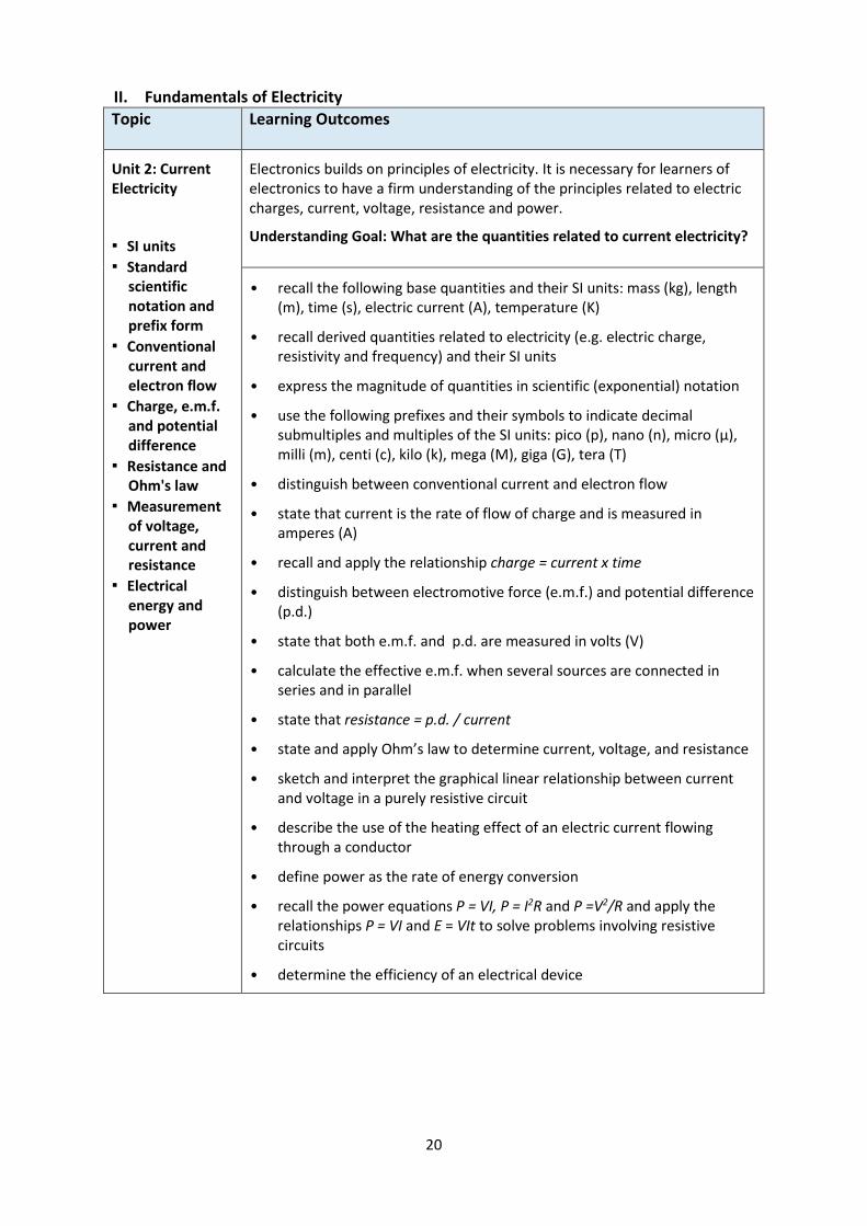
II. Fundamentals of Electricity
Topic Learning Outcomes
Unit 2: Current Electricity
▪ SI units
▪ Standard scientific notation and prefix form
▪ Conventional current and electron flow
▪ Charge, e.m.f. and potential difference
▪ Resistance and Ohm's law
▪ Measurement of voltage, current and resistance
▪ Electrical energy and power
Electronics builds on principles of electricity. It is necessary for learners of electronics to have a firm understanding of the principles related to electric charges, current, voltage, resistance and power.
Understanding Goal: What are the quantities related to current electricity?
• recall the following base quantities and their SI units: mass (kg), length (m), time (s), electric current (A), temperature (K)
• recall derived quantities related to electricity (e.g. electric charge, resistivity and frequency) and their SI units
• express the magnitude of quantities in scientific (exponential) notation
• use the following prefixes and their symbols to indicate decimal submultiples and multiples of the SI units: pico (p), nano (n), micro (μ), milli (m), centi (c), kilo (k), mega (M), giga (G), tera (T)
• distinguish between conventional current and electron flow
• state that current is the rate of flow of charge and is measured in amperes (A)
• recall and apply the relationship charge = current x time
• distinguish between electromotive force (e.m.f.) and potential difference (p.d.)
• state that both e.m.f. and p.d. are measured in volts (V)
• calculate the effective e.m.f. when several sources are connected in series and in parallel
• state that resistance = p.d. / current
• state and apply Ohm’s law to determine current, voltage, and resistance
• sketch and interpret the graphical linear relationship between current and voltage in a purely resistive circuit
• describe the use of the heating effect of an electric current flowing through a conductor
• define power as the rate of energy conversion
• recall the power equations P = VI, P = I2R and P =V2/R and apply the relationships P = VI and E = VIt to solve problems involving resistive circuits
• determine the efficiency of an electrical device
21
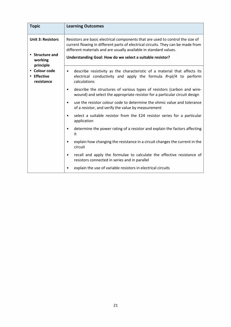
Topic Learning Outcomes
Unit 3: Resistors
▪ Structure and working principle
▪ Colour code
▪ Effective resistance
Resistors are basic electrical components that are used to control the size of current flowing in different parts of electrical circuits. They can be made from different materials and are usually available in standard values.
Understanding Goal: How do we select a suitable resistor?
• describe resistivity as the characteristic of a material that affects its electrical conductivity and apply the formula R=pl/A to perform calculations
• describe the structures of various types of resistors (carbon and wire-wound) and select the appropriate resistor for a particular circuit design
• use the resistor colour code to determine the ohmic value and tolerance of a resistor, and verify the value by measurement
• select a suitable resistor from the E24 resistor series for a particular application
• determine the power rating of a resistor and explain the factors affecting it
• explain how changing the resistance in a circuit changes the current in the circuit
• recall and apply the formulae to calculate the effective resistance of resistors connected in series and in parallel
• explain the use of variable resistors in electrical circuits

22
Topic Learning Outcomes
Unit 4: Circuit Theories
▪ Open and short circuits
▪ Series and parallel circuits
▪ Voltage and current dividers
▪ Kirchhoff's Voltage and Current law
A circuit consists of electrical paths that allow currents to flow. Components in an electronic system are connected as circuits. Circuit theories can be used to determine the voltages and currents at different parts of a given circuit. Knowledge of circuit theories is also necessary to design, build and troubleshoot electronic systems.
Understanding Goal: How can we determine the current and voltage at different points of a circuit?
• define the terms - circuit, load, source, open-circuit, short-circuit and overload
• show understanding that current flows only in a closed circuit
• show understanding of the effect of a short circuit
• apply the following principles to a series-parallel resistive circuit
- the current at every point in a series circuit is the same
- the sum of the p.d.s in a series circuit is equal to the p.d. across the whole circuit
- the current from the source is equal to the sum of the currents in the branches of a parallel circuit
- the p.d. across each branch of a parallel circuit is the same
• identify a resistive voltage divider and apply the voltage-divider formula to solve related problems
• identify a resistive current divider and apply the current-divider formula to solve related problems
• state and apply Kirchhoff's voltage and current laws
23
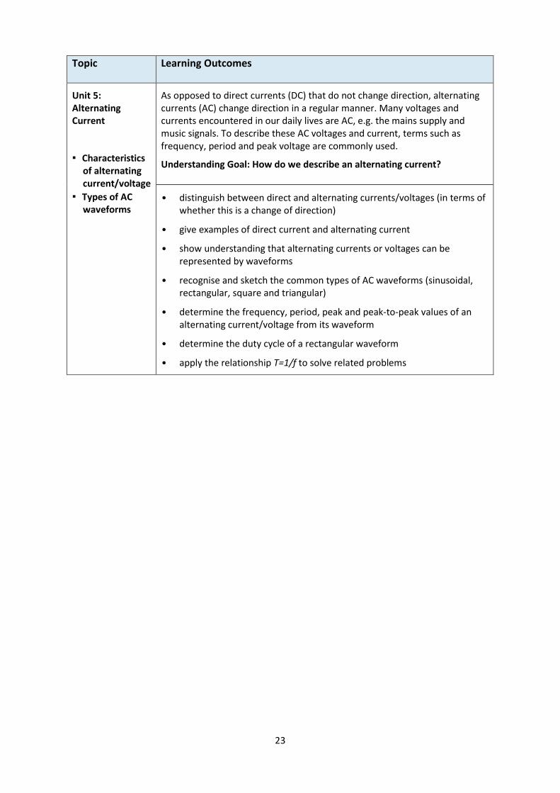
Topic Learning Outcomes
Unit 5: Alternating Current
▪ Characteristics of alternating current/voltage
▪ Types of AC waveforms
As opposed to direct currents (DC) that do not change direction, alternating currents (AC) change direction in a regular manner. Many voltages and currents encountered in our daily lives are AC, e.g. the mains supply and music signals. To describe these AC voltages and current, terms such as frequency, period and peak voltage are commonly used.
Understanding Goal: How do we describe an alternating current?
• distinguish between direct and alternating currents/voltages (in terms of whether this is a change of direction)
• give examples of direct current and alternating current
• show understanding that alternating currents or voltages can be represented by waveforms
• recognise and sketch the common types of AC waveforms (sinusoidal, rectangular, square and triangular)
• determine the frequency, period, peak and peak-to-peak values of an alternating current/voltage from its waveform
• determine the duty cycle of a rectangular waveform
• apply the relationship T=1/f to solve related problems
24
Topic Learning Outcomes
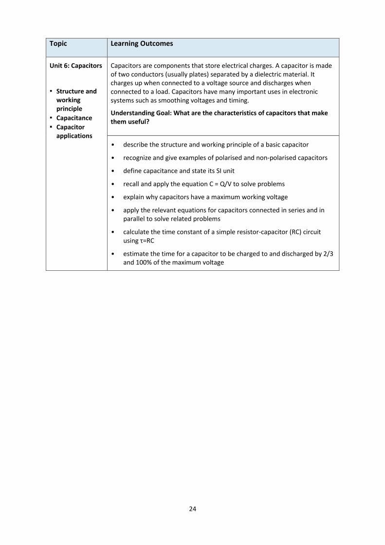
Unit 6: Capacitors
▪ Structure and working principle
▪ Capacitance
▪ Capacitor applications
Capacitors are components that store electrical charges. A capacitor is made of two conductors (usually plates) separated by a dielectric material. It charges up when connected to a voltage source and discharges when connected to a load. Capacitors have many important uses in electronic systems such as smoothing voltages and timing.
Understanding Goal: What are the characteristics of capacitors that make them useful?
• describe the structure and working principle of a basic capacitor
• recognize and give examples of polarised and non-polarised capacitors
• define capacitance and state its SI unit
• recall and apply the equation C = Q/V to solve problems
• explain why capacitors have a maximum working voltage
• apply the relevant equations for capacitors connected in series and in parallel to solve related problems
• calculate the time constant of a simple resistor-capacitor (RC) circuit using τ=RC
• estimate the time for a capacitor to be charged to and discharged by 2/3 and 100% of the maximum voltage
25
III. Analogue Electronics
Topic Learning Outcomes
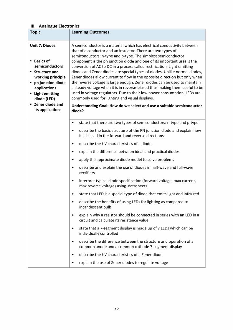
Unit 7: Diodes
▪ Basics of semiconductors
▪ Structure and working principle
▪ pn junction diode applications
▪ Light emitting diode (LED)
▪ Zener diode and its applications
A semiconductor is a material which has electrical conductivity between that of a conductor and an insulator. There are two types of semiconductors: n-type and p-type. The simplest semiconductor component is the pn junction diode and one of its important uses is the conversion of AC to DC in a process called rectification. Light emitting diodes and Zener diodes are special types of diodes. Unlike normal diodes, Zener diodes allow current to flow in the opposite direction but only when the reverse voltage is large enough. Zener diodes can be used to maintain a steady voltage when it is in reverse-biased thus making them useful to be used in voltage regulators. Due to their low power consumption, LEDs are commonly used for lighting and visual displays.
Understanding Goal: How do we select and use a suitable semiconductor diode?
• state that there are two types of semiconductors: n-type and p-type
• describe the basic structure of the PN junction diode and explain how it is biased in the forward and reverse directions
• describe the I-V characteristics of a diode
• explain the difference between ideal and practical diodes
• apply the approximate diode model to solve problems
• describe and explain the use of diodes in half-wave and full-wave rectifiers
• interpret typical diode specification (forward voltage, max current, max reverse voltage) using datasheets
• state that LED is a special type of diode that emits light and infra-red
• describe the benefits of using LEDs for lighting as compared to incandescent bulb
• explain why a resistor should be connected in series with an LED in a circuit and calculate its resistance value
• state that a 7-segment display is made up of 7 LEDs which can be individually controlled
• describe the difference between the structure and operation of a common anode and a common cathode 7-segment display
• describe the I-V characteristics of a Zener diode
• explain the use of Zener diodes to regulate voltage
26
Topic Learning Outcomes
Unit 8: Input and Output Transducer
▪ Basics of input and output transducers
▪ Thermistor, light dependent resistor (LDR), infra-red diode and microphone
▪ Loudspeaker, buzzer, motor and electromechanical relay
A transducer is a device that converts a signal from one form of energy to another. As electronic systems can only process electrical signals, input transducers play the important role of converting non-electrical quantities (e.g. temperature) to electrical signals. Output transducers then convert the outcomes of the process to non-electrical quantities. There are many different types of input and output transducers which are differentiated by the type of conversion they perform.
Understanding Goal: How do we select and use a suitable transducer?
• explain what is meant by an input and an output transducer
• give examples of input and output transducers
• recall and apply the effect of changes in temperature on the resistance of a thermistor to practical situations
• recall and apply the effect of changes in light intensity on the resistance of an LDR to practical situations
• interpret the characteristic graphs of thermistors and LDRs
• describe the use of infra-red diodes as transmitting and receiving devices
• describe the function of the following transducers: microphone, loudspeaker, buzzer, low voltage DC motor and electromagnetic relays
27
Topic Learning Outcomes
Unit 9: Bipolar Transistors
▪ Structure and working principle
▪ Operating regions
▪ BJT applications
A transistor is a 3-terminal semiconductor device. By applying a small current at one terminal, the current flowing between the other two terminals can be controlled. This property allows the transistor to be used as an amplifier or an electronic switch. Transistors are the basic building blocks of complex integrated circuits and the modern day computer processors consist of hundreds of millions of transistors packed into a small integrated circuit. A basic type of transistor is the bipolar junction transistor. Before it can be used, a BJT needs to be biased using an external circuit so that it will work in the correct operating region.
Understanding Goal: How do we select and use a suitable bipolar junction transistor?
• describe the structure of the two types of bipolar junction transistor (BJT)
• describe the working principle of a BJT (a base current controls current between emitter and collector)
• describe the different operating regions of BJTs
• relate the operating regions to the different segments of an IC-VCE
characteristic graph
• relate the operating regions to the use of BJT as a switch and an amplifier
• explain how a BJT can be biased to operate as a switch and an amplifier
• identify common base (CB), common collector (CC) and common emitter (CE) transistor circuits
• apply the relationship between the current, voltage and power of a transistor to solve related problems in common emitter circuits
• explain the function of coupling and bypass capacitors in transistor amplifier circuits
• calculate the approximate AC gain of a voltage-divider biased CE amplifier
• explain the advantage of a Darlington pair over a single transistor in driving an output transducer
• interpret typical BJT specifications (β, ICmax, VBE, VCE(sat)) using its datasheet
28
IV. Digital Electronics
Topic Learning Outcomes
Unit 10: Introduction to Digital Electronics
▪ Analogue and digital signals
▪ Pull up/down resistors
▪ 7 segment display module
Digital electronics is based on analogue electronics. Most modern electronic devices such as the personal computer and mobile phone, use digital electronics to tap on its advantages in terms of cost, size, speed and reliability. A key difference between analogue and digital electronics is the signal. While analogue signals take on continuous values, digital signals take on two discrete levels. For this reason, almost every digital system uses the binary number system. However, humans are more familiar with the decimal number system.
Understanding Goal: How do digital electronics systems work?
• identify analogue and digital signals from oscilloscope traces
• state that digital signals can be represented by two logic states: logic 1 (high voltage, usually 5 V); logic 0 (low voltage, usually 0 V)
• explain the use of ‘pull up’ and ‘pull down’ resistors to provide the correct logic levels
• list the advantages and disadvantages of digital systems over the analogue systems
• describe the need to convert between analogue and digital signals
• convert between binary, decimal and binary-coded decimal (BCD) systems
• describe the function of a BCD to 7-segment display module using a truth table

29
Topic Learning Outcomes
Unit 11: Basic Logic Gates
▪ Basic logic gates
▪ Universal gates
▪ Integrated Circuits (IC)
The basic building blocks of digital electronics are logic gates. Each logic gate is a system on its own with 1 or more inputs and one output. Logic gates are used to represent logical decisions which can be presented in the form of truth tables, logic symbols and Boolean notation. Two of the logic gates, NAND and NOR, are special gates called universal gates as they can be used to build all other types of logic gates.
Understanding Goal: How do we design and build a decision-making circuit?
• describe the truth table as a way to show the output of a digital circuit for different combinations of inputs.
• state that a logic gate is a device with one output and at least one input; the output is either logic ‘1’ or ‘0’ depending on the inputs
• draw symbols and construct truth tables for NOT, AND, OR, NAND and NOR gates
• use Boolean notation (‘—’, ‘.’ and ‘+’) to write the Boolean expression for NOT, AND, OR, NAND and NOR gates
• state that NAND and NOR gates are universal gates
• show how NOT, AND and OR gates can be made using NAND or NOR gates
• describe basic characteristics (e.g. general structure, pin configuration, common notation) of a dual in-line IC
• use datasheets to identify pin connections of common logic gate ICs
30
Topic Learning Outcomes
Unit 12: Combinational Logic Circuits
▪ Sum-of-Products Boolean expression
▪ Boolean Algebra & Karnaugh Map
▪ Applications of combinational logic
Combinational logic circuits are built using basic logic gates to achieve more complex functions. There are usually more inputs and outputs compared to a basic logic gate. Here, the combinational logic circuit can be viewed as a larger system with the basic logic gates functioning as sub-systems where the outputs are dependent on the inputs and how the logic gates are connected. A combinational logic circuit can also be simplified to achieve the same function with fewer logic gates, helping to save cost and make the circuit less prone to faults. Mathematical tools such as Boolean algebra and Karnaugh maps can help to perform such simplifications in a systematic manner.
Understanding Goal: How do we design and build a decision-making circuit?
• use a truth table to describe the output of a digital system (up to three inputs)
• convert a truth table (up to three inputs) into a sum-of-product (SOP) Boolean expression
• simplify an SOP Boolean expression (up to three variables) using either Boolean algebra or a Karnaugh Map
• implement logic circuits using NOT, AND and OR gates given an SOP Boolean expression
• describe and explain the function of a given combinational logic circuit
• solve system problems using combinations of logic gates (up to three inputs)

31
Topic Learning Outcomes
Unit 13: Memory – Set Reset (S-R) Latches
▪ NOR gate S-R Latch
▪ Debounced Switch
A key advantage of digital electronics is the ability to remember data. This ability enables digital circuits to perform more complex operations such as counting. The most basic circuit with memory is the S-R latch which can be used to store a single bit of data as either logic ‘1’ or ‘0’ allowing the latch to convert a momentary occurrence into a constant output. Timing diagrams are frequently used to describe and analyse circuits with memory. These diagrams show the logic state (‘1’ or ‘0’) of the system at any point in time and also the time when a change in state occurs.
Understanding Goal: How do we build a basic memory circuit?
• describe the S-R latch as a digital circuit with memory
• draw the symbolic representation of an S-R latch using NOR gates
• construct the truth table of an S-R latch and use the table to determine the output of the latch
• draw the output timing diagram of an S-R latch
• explain how an S-R latch is used to convert a momentary occurrence into a constant output
• explain how an S-R latch can be used to build a debounced switch
32
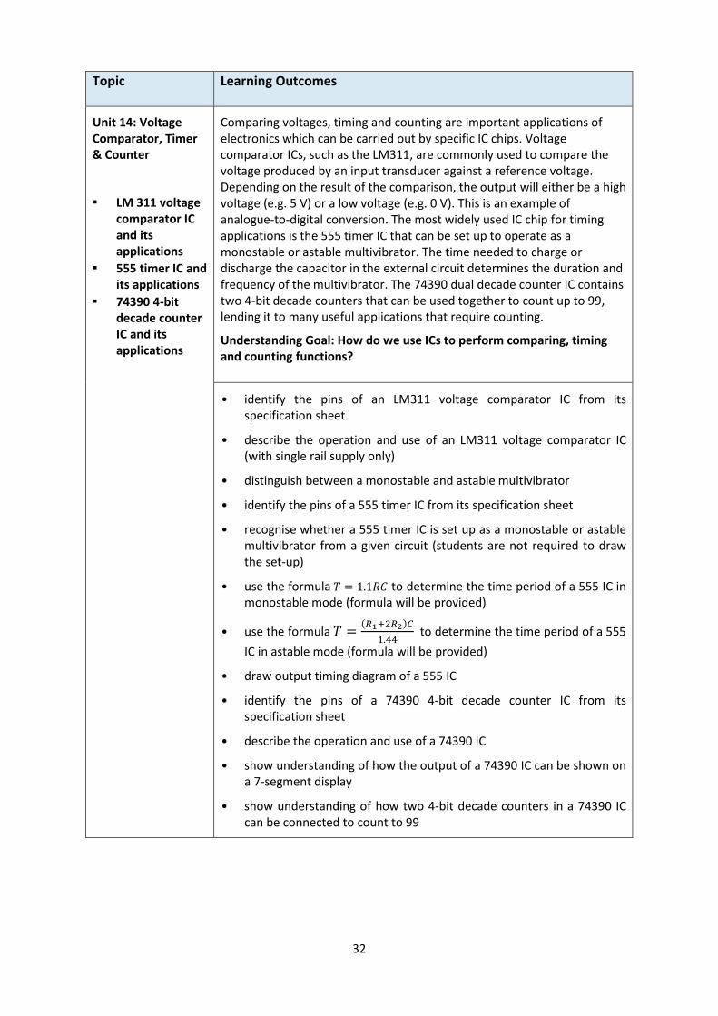
Topic Learning Outcomes
Unit 14: Voltage Comparator, Timer & Counter
▪ LM 311 voltage comparator IC and its applications
▪ 555 timer IC and its applications
▪ 74390 4-bit decade counter IC and its applications
Comparing voltages, timing and counting are important applications of electronics which can be carried out by specific IC chips. Voltage comparator ICs, such as the LM311, are commonly used to compare the voltage produced by an input transducer against a reference voltage. Depending on the result of the comparison, the output will either be a high voltage (e.g. 5 V) or a low voltage (e.g. 0 V). This is an example of analogue-to-digital conversion. The most widely used IC chip for timing applications is the 555 timer IC that can be set up to operate as a monostable or astable multivibrator. The time needed to charge or discharge the capacitor in the external circuit determines the duration and frequency of the multivibrator. The 74390 dual decade counter IC contains two 4-bit decade counters that can be used together to count up to 99, lending it to many useful applications that require counting.
Understanding Goal: How do we use ICs to perform comparing, timing and counting functions?
• identify the pins of an LM311 voltage comparator IC from its specification sheet
• describe the operation and use of an LM311 voltage comparator IC (with single rail supply only)
• distinguish between a monostable and astable multivibrator
• identify the pins of a 555 timer IC from its specification sheet
• recognise whether a 555 timer IC is set up as a monostable or astable multivibrator from a given circuit (students are not required to draw the set-up)
• use the formula 𝑇 = 1.1𝑅𝐶 to determine the time period of a 555 IC in monostable mode (formula will be provided)
• use the formula 𝑇 =(𝑅1+2𝑅2)𝐶
1.44 to determine the time period of a 555
IC in astable mode (formula will be provided)
• draw output timing diagram of a 555 IC
• identify the pins of a 74390 4-bit decade counter IC from its specification sheet
• describe the operation and use of a 74390 IC
• show understanding of how the output of a 74390 IC can be shown on a 7-segment display
• show understanding of how two 4-bit decade counters in a 74390 IC can be connected to count to 99
33
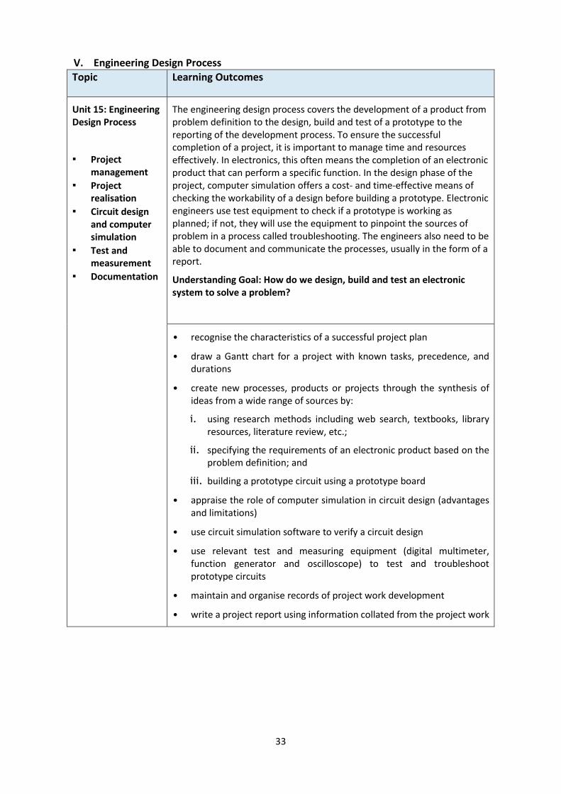
V. Engineering Design Process
Topic Learning Outcomes
Unit 15: Engineering Design Process
▪ Project management
▪ Project realisation
▪ Circuit design and computer simulation
▪ Test and measurement
▪ Documentation
The engineering design process covers the development of a product from problem definition to the design, build and test of a prototype to the reporting of the development process. To ensure the successful completion of a project, it is important to manage time and resources effectively. In electronics, this often means the completion of an electronic product that can perform a specific function. In the design phase of the project, computer simulation offers a cost- and time-effective means of checking the workability of a design before building a prototype. Electronic engineers use test equipment to check if a prototype is working as planned; if not, they will use the equipment to pinpoint the sources of problem in a process called troubleshooting. The engineers also need to be able to document and communicate the processes, usually in the form of a report.
Understanding Goal: How do we design, build and test an electronic system to solve a problem?
• recognise the characteristics of a successful project plan
• draw a Gantt chart for a project with known tasks, precedence, and durations
• create new processes, products or projects through the synthesis of ideas from a wide range of sources by:
i. using research methods including web search, textbooks, library resources, literature review, etc.;
ii. specifying the requirements of an electronic product based on the problem definition; and
iii. building a prototype circuit using a prototype board
• appraise the role of computer simulation in circuit design (advantages and limitations)
• use circuit simulation software to verify a circuit design
• use relevant test and measuring equipment (digital multimeter, function generator and oscilloscope) to test and troubleshoot prototype circuits
• maintain and organise records of project work development
• write a project report using information collated from the project work

34
This page is blank.

35
SECTION 3: PEDAGOGY
Alignment with Principals of Applied Learning
Attaining Goals of Syllabus Authenticity of Learning Experiences
Teaching & Learning Strategies

36
3. PEDAGOGY
Alignment with Principles of Applied Learning
Applied learning is a notion that is gathering momentum in many educational contexts around the world, and is often equated to ‘hands on’ or practical learning experiences. Despite the many definitions of what constitutes applied learning, a number of recurring themes can be found across these definitions. These themes can be viewed as the pedagogical principles that support applied learning:
emphasises the relevance of what is being learnt to the ‘real world’ outside the classroom, and makes that connection in an immediate and explicit manner;
requires students to use hands-on or experiential learning to enact authentic scenarios, where students focus on learning and applying the skills and knowledge they need to solve a problem and implement a project;
involves students and teachers in partnerships with the industries, community, institutions of higher learning, professional training bodies, and individuals outside school
Electronics aims to bring out the principles of applied learning through an approach that contextualises learning in a way that empowers and motivates students, while assisting them to develop key skills and knowledge required for further education and active participation in their communities. Hence, teachers should plan their teaching to offer plenty of hands-on exploration for their students to construct meaning for themselves, to learn in ways that allow them to directly apply knowledge so as to see the usefulness of electronic engineering in the creation of innovations to solve real world problems.
Attaining goals of syllabus
The syllabus aims to develop attitudes, skills and knowledge in electronics; and foster the interest in the engineering field. The knowledge includes concepts related to electricity and circuit theories; and how electronic components work so as to use them correctly to attain the desired intent. To design, build and test electronic circuits, students need to be proficient with using test equipment, building circuits and performing circuit simulation. The willingness, mental strength and confidence to take on challenges and setbacks are key traits of a successful engineer. The teaching strategies adopted should effectively be delivering these goals. Authenticity of learning experiences
In his book, “Making Learning Whole”, David Perkins illustrated how teaching any subject at any grade level can be made more effective if students are introduced to the ‘whole game’ rather than isolated pieces of a discipline. In electronic engineering, engineers work in teams and apply their knowledge and skills to design, build and test products that can solve real-life problems. Problem solving is what engineers do. It is what they are, or should be good at. Getting students to solve real-world problems provides students with an authentic experience of this engineering design process.

37
Teaching & Learning Strategies
In line with principles of applied learning, the central pedagogical approach adopted is “learning through doing”. This hands-on approach directly involves the learner, by actively encouraging them to do something in order to learn about it. Hands-on learning not only allows students to directly observe and understand what they have learnt, but also helps them to develop a range of engineering skills. In addition, it encourages students to do things for themselves, which will help them to learn independently later in life. Some strategies that can support learning through doing are:
Concept & skills building through guided practicals
Problem solving through mini projects
Use of ICT
Group work
Questioning using essential questions
Learning Journeys

38
This page is blank.

39
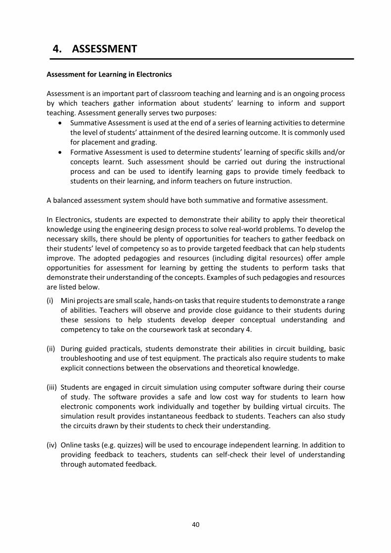
SECTION 4: ASSESSMENT
Assessment for Learning in Electronics
The O-Level Examination for Electronics
40
4. ASSESSMENT
Assessment for Learning in Electronics Assessment is an important part of classroom teaching and learning and is an ongoing process by which teachers gather information about students’ learning to inform and support teaching. Assessment generally serves two purposes:
Summative Assessment is used at the end of a series of learning activities to determine the level of students’ attainment of the desired learning outcome. It is commonly used for placement and grading.
Formative Assessment is used to determine students’ learning of specific skills and/or concepts learnt. Such assessment should be carried out during the instructional process and can be used to identify learning gaps to provide timely feedback to students on their learning, and inform teachers on future instruction.
A balanced assessment system should have both summative and formative assessment. In Electronics, students are expected to demonstrate their ability to apply their theoretical knowledge using the engineering design process to solve real-world problems. To develop the necessary skills, there should be plenty of opportunities for teachers to gather feedback on their students’ level of competency so as to provide targeted feedback that can help students improve. The adopted pedagogies and resources (including digital resources) offer ample opportunities for assessment for learning by getting the students to perform tasks that demonstrate their understanding of the concepts. Examples of such pedagogies and resources are listed below.
(i) Mini projects are small scale, hands-on tasks that require students to demonstrate a range of abilities. Teachers will observe and provide close guidance to their students during these sessions to help students develop deeper conceptual understanding and competency to take on the coursework task at secondary 4.
(ii) During guided practicals, students demonstrate their abilities in circuit building, basic
troubleshooting and use of test equipment. The practicals also require students to make explicit connections between the observations and theoretical knowledge.
(iii) Students are engaged in circuit simulation using computer software during their course
of study. The software provides a safe and low cost way for students to learn how electronic components work individually and together by building virtual circuits. The simulation result provides instantaneous feedback to students. Teachers can also study the circuits drawn by their students to check their understanding.
(iv) Online tasks (e.g. quizzes) will be used to encourage independent learning. In addition to
providing feedback to teachers, students can self-check their level of understanding through automated feedback.

41
The GCE O-Level Examination for Electronics Students sit for the GCE O-Level Electronics examination at Secondary 4. The assessment objectives, weighting and scheme of assessment are as follows: Assessment Objectives A Knowledge with Understanding Candidates should be able to demonstrate knowledge and understanding of scientific facts, concepts, theories and terminology in relation to: 1. electronic systems 2. electricity and circuit theories 3. electrical and electronic components 4. digital electronics. B Handling Information and Solving Problems Candidates should be able to: 1. locate, select, interpret and evaluate information 2. manipulate numerical and other data 3. present reasoned explanations for application and relationships between components 4. solve problems. C Practical Skills and Project Realisation Candidates should be able to design, build and test electronic systems involving the following processes: 1. observe, measure and record data accurately 2. analyse problems by considering relevant functional and practical factors 3. conduct research, plan, design and develop solutions 4. use computer simulation software to verify design 5. build a prototype circuit using a prototype board 6. use appropriate test and measurement equipment to test and troubleshoot a
prototype circuit 7. present evaluative report on design and solutions to problems.
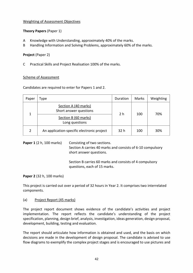
42
Weighting of Assessment Objectives Theory Papers (Paper 1) A Knowledge with Understanding, approximately 40% of the marks. B Handling Information and Solving Problems, approximately 60% of the marks. Project (Paper 2) C Practical Skills and Project Realisation 100% of the marks.
Scheme of Assessment
Candidates are required to enter for Papers 1 and 2.
Paper Type Duration Marks Weighting
1
Section A (40 marks) Short answer questions
2 h 100 70% Section B (60 marks)
Long questions
2 An application-specific electronic project 32 h 100 30%
Paper 1 (2 h, 100 marks) Consisting of two sections.
Section A carries 40 marks and consists of 6-10 compulsory short answer questions.
Section B carries 60 marks and consists of 4 compulsory questions, each of 15 marks.
Paper 2 (32 h, 100 marks) This project is carried out over a period of 32 hours in Year 2. It comprises two interrelated components. (a) Project Report (45 marks)
The project report document shows evidence of the candidate’s activities and project implementation. The report reflects the candidate’s understanding of the project specification, planning, design brief, analysis, investigation, ideas generation, design proposal, development, building, testing and evaluation.
The report should articulate how information is obtained and used, and the basis on which decisions are made in the development of design proposal. The candidate is advised to use flow diagrams to exemplify the complex project stages and is encouraged to use pictures and

43
graphical illustrations in the report. Due recognition and acknowledgement should be accorded to information sources and person/s rendering help to the project.
The report should include a description of the strengths and weaknesses of the design and how problems, and issues surrounding the project were resolved.
(b) The Project Hardware (55 marks)
The candidate is expected to demonstrate good quality work, appropriate use of electronic components and constructional methods.