electronics presentation 06
TRANSCRIPT


What is Electronics?
Power and control system of the robot Includes the battery, computer, circuit
breakers, various power controllers, and wires
Computer sends signals to power controllers, which allow or restrict power to their assigned robot component

Electronic System Components
Computer Circuit Breaker(s) Victors Spikes Batteries Main Power Switch Grounding Stud Power Distribution block Sensors
Computer
Brain of the robot Relays information from programming or
sensors with either PWM or relay cables Has backup power source-little blue battery


Circuit Breakers
Prevent power surges by limiting amount of power flow
Amount of flow allowed based on fuses Come in 20, 30, and 40 amp 40 amp always used for drive motors Otherwise depends on specific power needs of
system


Victors
Used for motors mostly 1 victor per motor
Variable settings Require 40 amp fuse in circuit breaker

Spikes
Used for compressor, pistons, and some motors 1 per compressor 1 or 2 per piston
Act through solenoids in pneumatics system Motors must have at most 30 amp load and no
intermediate positions-not often used Breaker fuse is 20 or 30 amp depending on
power needed for each system


Batteries
Contain all power for the robot Are removable for charging
Connected to rest of power system with a power coupling
1 big battery for main power 1 small battery for computer


Main Power Switch
Controls all power from battery to robot Top button-off Side button-on Connected only to (+) wires

Grounding Stud
Final destination of all (-) wires Makes sure no power goes into the metal
robot


Power Distribution Block
Only way to make big wires smaller besides breakers
Splits power from one big wire into many smaller wires
Not always used on robot


Sensors
Gets information from surroundings and delivers messages to computers
Connects only to the computer and is there dealt with by the programming
Examples: camera, touch sensors, IR sensors, line sensors
We have not used them often


A Typical Electronics Diagram

Wiring parts
Wires have different sizes (gauges)
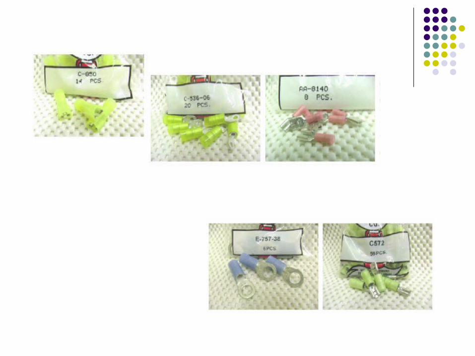
Connectors Different colors show different sizes
Blue<Red <Yellow (others are relatively obvious by sight)
We generally work with 3 different shapes Many types depending on way of attachment
Crimp and solder are two main kinds


Wiring Process
Attach all electronic components to a board-for us plastic
Know where wires go Measure length of wires-checking on the electronics
board multiple times-then cut Attach appropriate connectors-those that fit with the
components and wire size Attach wires to components If have time, organize wires and zip tie together to
look less jumbled
Rules for Wiring
(+) is usually a red wire (sometimes white) (-) is usually black wire (sometimes blue) Never directly connect a bigger wire to a smaller
wire Can always go through something like a power distribution
block or circuit breaker
Always surround connections with electrical tape When in doubt, look at the diagram or ask someone-
DO NOT TAKE CHANCES Chances can lead to electrical fires
