electronics worlá - world radio history
TRANSCRIPT
Electronics Worlá jET TRANSPORT COMMUNICATIONS
WHICH TAPE TO USE?
CHOOSING A TWO-WAY RADIO SYSTEM
THE ROLE Of THE LAB TECHNICIAN i,Leu.v.eikatv. 0:
OCT i7 19i-3
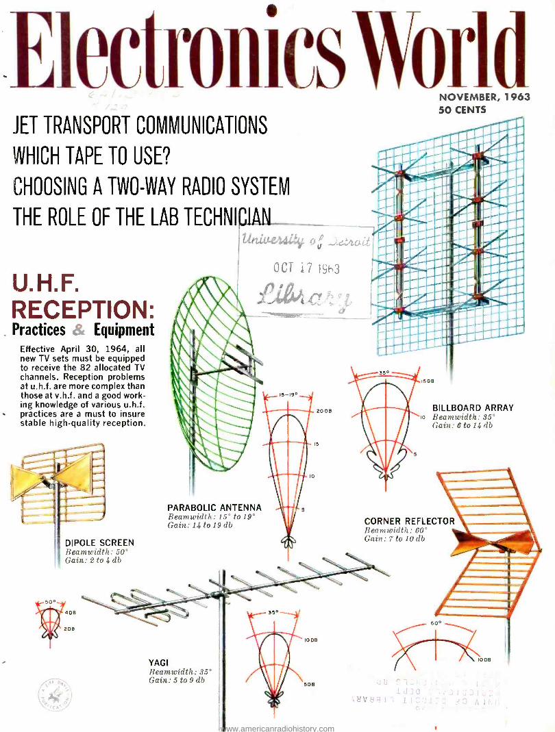
.111.044 U.H.F. RECEPTION: Practices Equipment
Effective April 30, 1964, all new TV sets must be equipped to receive the 82 allocated TV channels. Reception problems at u.h.f. are more complex than those at v.h.f. and a good work- ing knowledge of various u.h.f. practices are a must to insure stable high -quality reception.
DIPOLE SCREEN Beamwidth : 50° Gain: 2 to 4 db
NOVEMBER, 1963 50 CENTS
PARABOLIC ANTENNA Beamwidth: 15° to 19° Gain: 14 to 19 db
5DB
BILLBOARD ARRAY o Beam width :35°
Gain: 6 to 14 db
CORNER REFLECTOR Kea in width : Go
Gait: 7 to 10 db
YAGI Beamwidth: 35° Gain: 5 to 9 db
10DB
6DB
60°
www.americanradiohistory.com
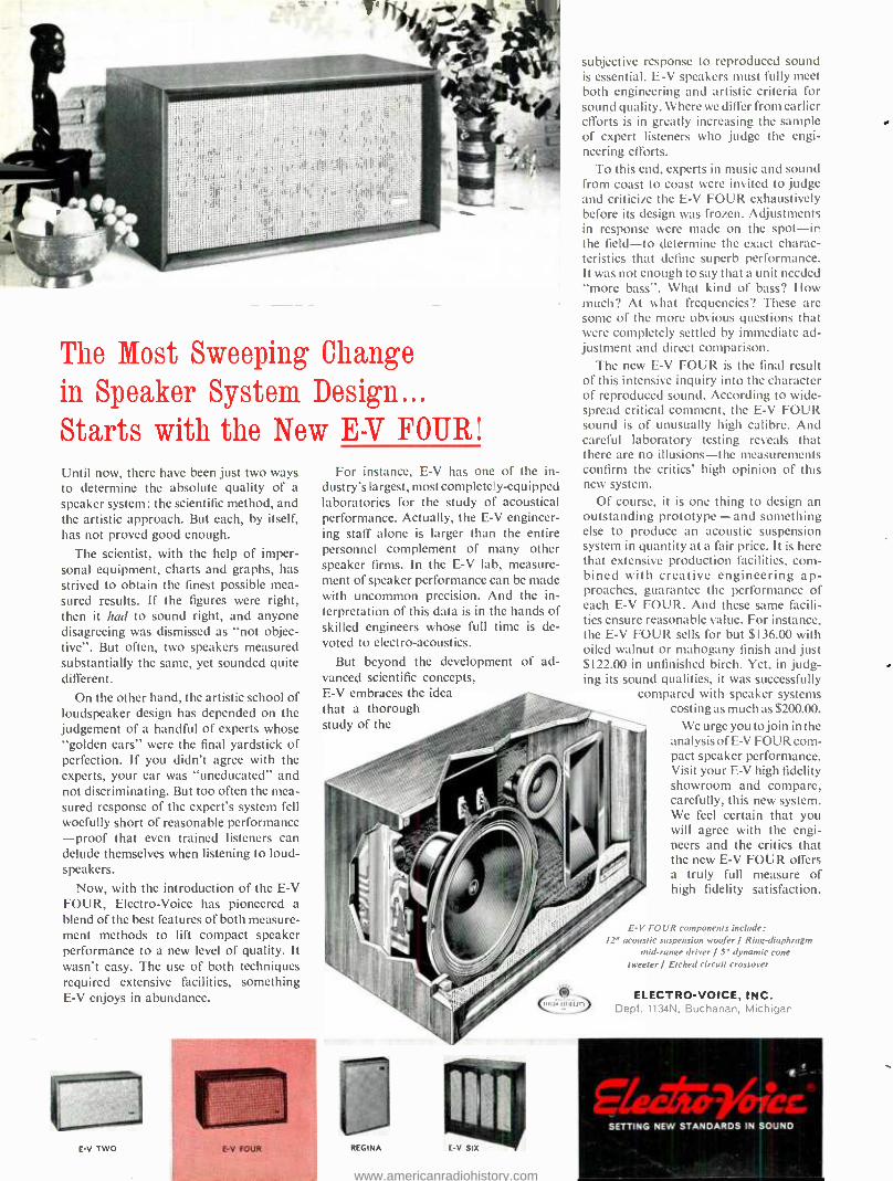
The Most Sweeping Change in Speaker System Design... Starts with the New E-V FOUR! Until now, there have been just two ways to determine the absolute quality of a speaker system: the scientific method, and the artistic approach. But each, by itself, has not proved good enough.
The scientist, with the help of imper- sonal equipment, charts and graphs, has strived to obtain the finest possible mea- sured results. If the figures were right, then it had to sound right, and anyone disagreeing was dismissed as "not objec- tive". But often, two speakers measured substantially the same, yet sounded quite different.
On the other hand, the artistic school of loudspeaker design has depended on the judgement of a handful of experts whose "golden ears" were the final yardstick of perfection. If you didn't agree with the experts, your ear was "uneducated" and not discriminating. But too often the mea- sured response of the expert's system fell woefully short of reasonable performance -proof that even trained listeners can delude themselves when listening to loud- speakers.
Now, with the introduction of the E -V FOUR, Electro -Voice has pioneered a blend of the best features of both measure- ment methods to lift compact speaker performance to a new level of quality. It wasn't easy. The use of both techniques required extensive facilities, something E -V enjoys in abundance.
1.141.1111"
E-V TW(:
For instance, E -V has one of the in- dustry's largest, most completely -equipped laboratories for the study of acoustical performance. Actually, the E -V engineer- ing staff alone is larger than the entire personnel complement of many other speaker firms. In the E -V lab, measure- ment of speaker performance can be made with uncommon precision. And the in- terpretation of this data is in the hands of skilled engineers whose full time is de- voted to electro- acoustics.
But beyond the development of ad- vanced scientific concepts, E -V embraces the idea that a thorough study of the
subjective response to reproduced sound is essential. E -V speakers must fully meet both engineering and artistic criteria for sound quality. Where we differ from earlier efforts is in greatly increasing the sample of expert listeners who judge the engi- neering efforts.
To this end, experts in music and sound from coast to coast were invited to judge and criticize the E -V FOUR exhaustively before its design was frozen. Adjustments in response were made on the spot -in the field -to determine the exact charac- teristics that define superb performance. It was not enough to say that a unit needed "more bass ". What kind of bass? How much? At what frequencies? These are some of the more obvious questions that were completely settled by immediate ad- justment and direct comparison.
The new E -V FOUR is the final result of this intensive inquiry into the character of reproduced sound. According to wide- spread critical comment, the E -V FOUR sound is of unusually high calibre. And careful laboratory testing reveals that there are no illusions -the measurements confirm the critics' high opinion of this new system.
Of course, it is one thing to design an outstanding prototype -and something else to produce an acoustic suspension system in quantity at a fair price. It is here that extensive production facilities, com- bined with creative engineering ap- proaches, guarantee the performance of each E -V FOUR. And these same facili- ties ensure reasonable value. For instance, the E -V FOUR sells for but $136.00 with oiled walnut or mahogany finish and just $122.00 in unfinished birch. Yet, in judg- ing its sound qualities, it was successfully
compared with speaker systems costing as much as $200.00.
We urge you to join in the analysis of E -V FOUR corn - pact speaker performance. Visit your E -V high fidelity showroom and compare, carefully, this new system. We feel certain that you will agree with the engi- neers and the critics that the new E -V FOUR offers a truly full measure of high fidelity satisfaction.
r>FC,r:n
E -V FOUR components include: 12" acoustic suspension woofer / Ring -diaphragm
mid -range driver I S' dynamic cone tweeter / Etched circuit crossover
ELECTRO- VOICE, INC. Dept. 1134N, Buchanan, Michigan
SETTING NEW STANDARDS IN SOUND
www.americanradiohistory.com
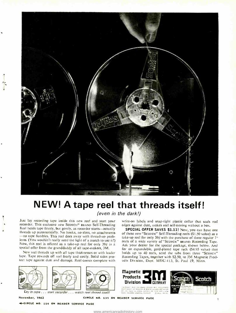
NEW! A tape reel that threads itself! (even in the dark!)
Just lay recording tape inside this new reel and start your recorder. This exclusive new SCOTCH® BRAND Self- Threading Reel holds tape firmly, but gently, as recorder starts -actually threads up automatically. No hooks, no slots, no attachments -no tape fumbles. This reel does away with thread -up prob- lems. (You wouldn't really need the light of a match to use it!) Now, this reel is offered as a take -up reel for only 39¢ in a special offer from the granddaddy of all tape- makers, 3M.
New reel threads up with all tape thicknesses or with leader tape. Tape rewinds off reel freely and easily. Solid sides pro- tect tape against dust and damage. Reel comes complete with
Lay in tape ... start recorder ... watch reel thread itself!
November, 1963 CIRCLE NO. 135 ON
4-CIRCLE NO. 116 ON READER SERVICE PACE
write -on labels and snap -tight plastic collar that seals reel edges against dust, makes reel self -storing without a box.
SPECIAL OFFER SAVES $1.11! Now, you can have one of these new "Scored" Self- Threading reels ($1.50 value) as a take -up reel for only 390 with the purchase of three regular 7" reels of a wide variety of "SCOTCH" BRAND Recording Tape. Ask your dealer for the special package, shown below. And for an expandable, gold -plated tape rack ($4.95 value) that holds up to 40 reels, send the tabs from three "ScorcH" Recording Tapes, together with $2.50, to 3M Magnetic Prod- ucts Division, Dept. MDU -113, St. Paul 19, Minn.
magnetic Products Division a COMPANY
READER SERVICE PAGE 1
www.americanradiohistory.com
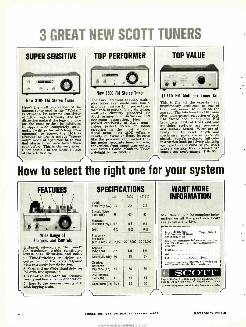
3 GREAT NEW SCOTT TUNERS
SUPER SENSITIVE
, .®11=11: 0 n . to)
New 310E FM Stereo Tuner
Here's the multiplex version of the famous tuner used in the "Telstar" experiment. Its extreme sensitivity of 1.9µv, high selectivity, and low distortion make it the logical choice for the most critical installations. Equipped with completely auto- matic facilities for switching from monaural to stereo, the 310E is effortless to use. A unique "stereo only" mode of operation helps you find stereo broadcasts faster than ever before. This is the very finest tuner possible at the present state of the art. $279.95
TOP PERFORMER
.1:2111111=1 0 . -
New 350C FM Stereo Tuner
The first, and most popular, multi- plex tuner ever made now has a new look, and vastly improved per- formance to match! Time- Switching multiplex circuitry pioneered by Scott assures low distortion and maximum separation. New im- proved sensitivity of 2.2µv guar- antees perfect stereo or mono reception in the most difficult signal areas. The 350C offers a variety of exclusive Scott features like the precision illuminated tun- ing meter, separate level controls, convenient front panel tape outlet, and Scott's Sonic Monitor. Truly a delight to use. $224.95
TOP VALUE
LT -110 FM Multiplex Tuner Kit
This is the kit the experts have unanimously acclaimed as one of the finest, easiest to build on the market. The fabulous LT -110 tuner gives unsurpassed reception of both FM Stereo and monophonic FM broadcasts. Critical front end and multiplex sections are pre -wired and factory tested. Wires are al- ready cut to exact length and mechanical parts are in place on chassis. Scott's exclusive full -color instruction book positively identifies each part in full color so you can't make a mistake. Even a novice can expect top performance. $164.95
How to select the right one for your system
FEATURES
Wide Range of Features and Controls
1. Heavily silver- plated "front -end" for maximum usable sensitivity, lowest hum, distortion, and noise. 2. Time -Switching multiplex cir- cuitry for full frequency response with extremely low distortion. 3. Famous 2 me Wide -Band detector for drift -free operation. 4. Sensitive indicator for .accurate tuning and best antenna orientation. 5. Easy -to -use vernier tuning dial with logging scale.
SPECIFICATIONS 310E 350C LT -110
Usable Sensitivity (µv) 1.9 2.2 2.2
Signal: Noise Ratio (db) 65 60 60
Harmonic Distortion (%) 0.5 0.8 0.8
Drift 0.02 0.02 0.02
Frequency Response (cps±ldb) 30- 15,000 30- 15,000 30- 15,000
Capture Ratio (db) 2.2 6.0 6.0
Selectivity (db) 50 35 35
Spurious Response Rejection (db) 85 80 80
AM Suppres- sion (db) 60 55 55
Separation (db) 30+ 30 30+
WANT MORE INFORMATION
Mail this coupon for complete infor- mation on all the great new Scott components and kits.
_t
H. H. Scott, Inc. 111 Powdermill Road Maynard, Mass.
Send me complete information on the new 1964 Scott line of stereo components and kits. Name Address City Zone... .State Include names of interested friends and we'll send them duplicate materials.
Dept. 160 -11
0 SCOTT Export: Morhan Exporting Corp., 458 Broadway, N.Y.C.
Canada : Atlas Radio Corp., 50 Wingold Ave., Toronto
All prices slightly higher west et Rockies. Accessory aies extra.
2 CIRCLE NO. 146 ON READER SERVICE PAGE ELECTRONICS WORLD
www.americanradiohistory.com
I](CI FOIÌICS \\oiId CONTENTS
27 Jet Transport Communications R. L. Conhaim
31 Parallel- Resistor Chart Larry W. Brindley
32 Recent Developments in Electronics
34 Which Tape to Use? Herman Burstein
36 New Citizens Band Circuits Len Buckwalter
37 U.H.F. Reception: Practices and Equipment Jack Beever
40 The Electronics Lab Technician C. Glickstein
43 Phasemeter for Audio Frequencies Thomas E. Reamer
47 New Light- Operated Switch Donald E. Whateley
48 Transistors vs Tubes for Hi -Fi Edward S. Miller, R. Grodinsky, and C. Westra
50 Choosing a Two -Way Radio System (Part 1) Howard H. Rice
53 Inside a Digital Voltmeter Sam Messin
66 A Transistorized Tachometer Carl David Todd
74 European Receiving -Tube Numbering System E. L. Elizondo
92 The Shrunken Raster: A Puzzler Art Widmann
95 Television Waveform Quiz Robert P. Balín
96 Making Special Resistors Robert Jones
12 For the Record (Editorial) \ r 1. III I i 'I W. A. Stocklin
22 EW Lab Tested Irony rh l" l'ImSI for /Ilirily
Imtio lhnnnrir. 1111:1 / "/,rul.rr " t,r,r
60 A "New Look in V.O.M.'s John Frye
86 Test Equipment Product Report lrro 1/n Ill i ;lltli /ll, lop/ lllIta 1í1!I..' ILL . /rn/rrdunee lirid_r l'iluovv íl01111 (I Photo Taelurnu ter
MONTHLY FEATURES Coming Next Month 4 Radio & TV News 76 Letters from Our Readers ... 14 Book Reviews 101 Reader Service Page 17 New Products & Literature .. 103
Copyright 1963 ny 2,11O.lvii Publishing Co,nn.lny. All r:; his reserved. rv.tl.
November, 1963
NOVEMBER 1963 VOL. 70 NO. 5
I:IitI iunics \\orId
UHF RECEPTION:
r j ï
OUR COVER shows some typical u.h.f. receiving an- tennas with their associated reception patterns and ap- proximate gain figures. The many varieties of patterns point up the fact that an an- tenna should be chosen for a particular installation de- pending on signal strengt,1, multi -path problems, and how far apart stations are with respect to antenna axis. Besides u.h.f. antennas, the article starting on page 37 also discusses u.h.f. con- verters, choosing the correct transmission line, and other information required in or- der to obtain best possible u.h.f. reception (Cover illus- tration by Otto E. Markevics.)
Publisher PHILLIP T. HEFFERNAN
Editor WM. A. STOCKLIN
Technierrl Edit MILTON S. SNITZER
Associate 1.1/110/ LESLIE SOLOMON
Associate liditol P. B. HOEFER
Editorial Consultant OLIVER READ
Industrial Consultant WALTER H. BUCHSBAUM
.l it Editor MILTON BERWIN
Art and Draping Dept. J. A. GOLANEK
Advertising Sales .11anag,'r LAWRENCE SPORN
Advertising Service .Manager ARDYS C. MORAN
3
www.americanradiohistory.com
captured by Concord
THE INTERGALACTIC
FORMULA FOR
AUDIOSONIC CALCULATION
4 track stereo record
and playback
3 speeds: ', 3 %,1Y
2 separated 6" speakers 2 dynamic microphones
I. low price
10 good reasons why you should own a
Concord 550 priced under $320
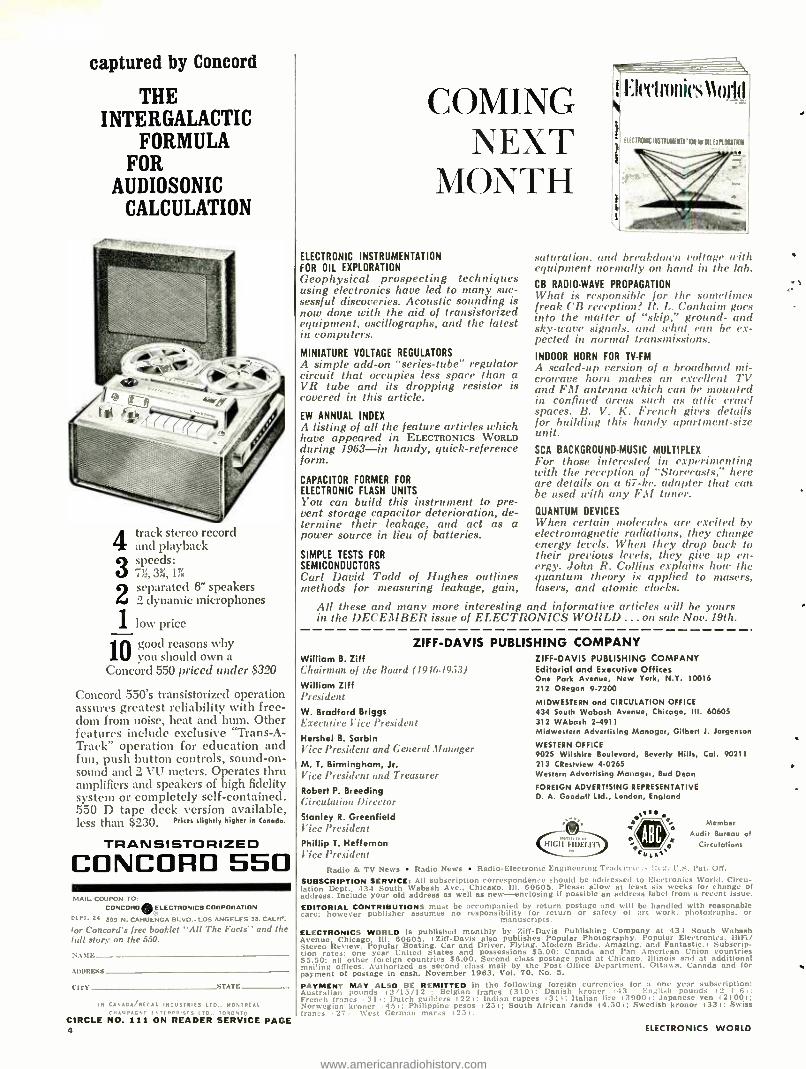
Concord 550's transistorized operation assures greatest reliability with free- dom from noise, heat and hum. Other features include exclusive "Trans -A- Track" operation for education and fun, push button controls, sound -on- sound and 2 VU meters. Operates thru amplifiers and speakers of high fidelity system or completely self -contained. 550 D tape deck version available, less than $230. Prices slightly higher in Ceneda.
TRANSISTORIZED CONCORD 550 MAIL COUPON 10
CONCORD ® ELECTRONICS CORPORATION
OLPI 24 £03 N. CAHUENGA BLVD.. LOS ANGELES 39, CALIF.
for Concord's free booklet "AIL The Facts" and the lull story on the 550.
NAUE_- .
ADURES,, .
CIrY- __STATE
MONTREAL
ONTO
CIRCLE NO. 111 ON READER SERVICE PAGE 4
T ; I;('('IIYIIII('ti11(IIÌ COMII NEXT
AIONTH
ELECTRONIC INSTRUMENTATION FOR OIL EXPLORATION Geophysical prospecting techniques using electronics have led to many suc- sessful discoveries. Acoustic sounding is now done with the aid of transistorized equipment, oscillographs, and the latest in computers.
MINIATURE VOLTAGE REGULATORS A simple add -on "series- tube" regulator circuit that occupies less space than a VR tube and its dropping resistor is covered in this article.
EW ANNUAL INDEX A listing of all the feature articles which have appeared in ELECTRONICS WORLD during 1963 -in handy, quick -reference form.
CAPACITOR FORMER FOR
ELECTRONIC FLASH UNITS You can build this instrument to pre- vent storage capacitor deterioration, de- termine their leakage, and act as a power source in lieu of batteries.
SIMPLE TESTS FOR
SEMICONDUCTORS Carl David Todd of Hughes outlines methods for measuring leakage, gain,
(I I C IRONIC INSTRUMENTI40N te Rl (MURCIA
saturation. and breakdown voltage with equipment normally on hand in the lab. CB RADIO -WAVE PROPAGATION What is responsible for the sometimes freak CB reception? R. L. Conhaim goes into the matter of "skip," ground- and sky -wave signals. and what can he ex- pected in normal transmissions. INDOOR HORN FOR TV-FM A scaled -up version of a broadband mi- crowave horn makes an excellent TV and FM antenna which can he mounted in confined areas such as attic crawl spaces. B. V. K. French gives details for building this handy apartment -size unit. SCA BACKGROUND-MUSIC MULTIPLEX For those interested in experimenting with the reception of "Storeeasts," here are details on a 67 -he. adapter that can be used with any F.l! tuner. QUANTUM DEVICES When certain molecules are excited by electromagnetic radiations, they change energy levels. When they drop back to their previous levels, they give up en- ergy. John R. Collins explains how the quantum theory is applied to masers, lasers, and atomic clocks.
All these and many more interesting and informative articles will he yours in the DECEMBER issue of ELECTRONICS WORLD ...on sale Nov. 19th.
ZIFF-DAVIS William B. Ziff Chairman of the Hoard (1946. 1953)
William Ziff President W. Bradford Briggs Executive Vice !'resident Hershel B. Sarbin Vice !'resident and General Manager M. T. Birmingham, Jr. I'ice l'resident and Treasurer Robed P. Breeding Circulation Director Stanley R. Greenfield Vice !'resident Phillip T. Heffernan Tice President
PUBLISHING COMPANY ZIFF -DAVIS PUBLISHING COMPANY Editorial and Executive Offices One Park Avenue, New York, N.Y. 10016 212 ORegon 9 -7200
MIDWESTERN and CIRCULATION OFFICE 434 South Wabash A , Chicago, III. 60605 312 WAbash 2 -4911 Midwestern Advertising Manager, Gilbert J. Jorgenson
WESTERN OFFICE 9025 Wilshire Boulevard, Beverly Hills, Cal. 90211 213 CRestview 4 -0265 Western Advertising Manager, Bud Dean
FOREIGN ADVERTISING REPRESENTATIVE D. A. Goodall Ltd., London, England
HIGH FIDELITY
Member Audit Bureau of
Circulations
Radio & TV News Radio News Radio -Electronic Engineering Tradcnru ;.. Ce;;. U.S. Pat. OR.
SUBSCRIPTION SERVICE: All subscription correspondence should be addressed to Electronics World. Circu- lation Dept.. 134 South Wabash Ave.. Chicago. Ill. 60605. Please allow at least six weeks for change of address. Include your old address as well as new -enclosing if possible an address label from a recent issue.
EDITORIAL CONTRIBUTIONS must be accompanied by return postage and will be handled with reasonable care; however publisher assumes no responsibility for return or safety of art work. photographs. or
manuscripts.
ELECTRONICS WORLD Is published monthly by Ziff -Davis Publishing Company at 434 South Wabash Avenue, Chicago. Ill. 60605. (Ziff -Davis also publishes Popular Photography. Popular Electronics. IIEFi/ Stereo Review. Popular Boating. Car and Driver. Flying. Modern Bride. Amazing. and Fantastic.) Subscrip- tion rates: one year United States and possessions $5.00: Canada and Pan American Union countries S5.50: all other foreign countries S6.00. Second class postage paid at Chicago. Illinois and at additional mailing offices. Authorized as second class mail by the Post Orrice Department. Ottawa. Canada and for payment of postage in cash. November 1963, Vol. 70, No. 5.
PAYMENT MAY ALSO BE REMITTED in the following foreign currencies for a one year subscription: Australian pounds i 2 '15/12 : Belgian francs (310): Danish kroner i 13 : English pounds i 2 a 6 i :
French francs 31 : Dutch guilders 1 221: Indian rupees i 31): Italian lire (39001: Japanese yen (2100i; Norwegian kroner 45 : Philippine pesos i 23 i; South African rands 14.501; Swedish kronor (33i: Swiss francs 27 : \Vest German marls i 23 1.
ELECTRONICS WORLD
www.americanradiohistory.com
not all cardioid microphones
are alike ... only the
SHURE BROTHERS, INC.
222 Hartrey Ave.
Evanston, Illinois
i
TIMDYXE TRUE CARDIOID UNIDIRECTIONAL DYNAMIC
MICROPHONE SOLVES ALL THESE
COMMON MICROPHONE PROBLEMS! MODEL 545S
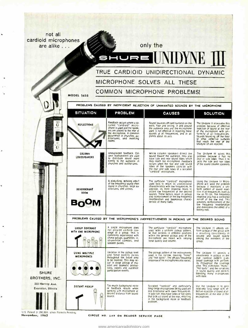
PROBLEMS CAUSED BY INEFFICIENT REJECTION OF UNWANTED SOUNDS BY THE MICROPHONE
SITUATION PROBLEM CAUSES SOLUTION
REFLECTIONS Feedback occurs where a so called "cardioid" micro- phone is used and the speak- ers are placed to the rear of the microphone. A common occurrence in churches, au- ditoriums, and meeting rooms.
Sound bounces off hard surfaces on the walls, floor and ceiling, in and around the audience area and the microphone used is not effective in rejecting these sounds at all frequencies, and in all planes about its axis.
The Unidyne III eliminates this problem because of effective rejection of sound at the rear of the microphone with uni- formity at all frequencies. Sounds bouncing off the floor or other reflective surfaces that reach the rear of the Unidyne III are rejected.
COLUMN
LOUDSPEAKERS
Unexplained feedback. Col- umn loudspeakers are used to distribute sound more evenly to the audience in churches and auditoriums.
While column speakers direct the sound toward the audience, they also have side and rear sound lobes which may reach the microphone. Feedback occurs when the rear and side sound lobes of the speakers coincide with the rear and side lobes Of a so-called "cardioid" microphone.
The Unidyne III solves this problem because it has no rear or side lobes. Thus it re- jedts the side and rear lobes of the sound column speakers.
REVERlERANT
BOOM
BO OM
A disturbing, echoing effect of low frequency sound often found in churches, large au- ditoriums, and arenas.
The particular "cardioid" microphone used fails to retain its unidirectional characteristics with low frequencies. In addition, its front response tends to accent low frequencies of the desired Sounds. These factors result in pickup and reinforcement of the low frequency reverberation and boominess charac- teristic Of many halls,
Using the Unidyne III Micro - phone will solve the problem because it maintains a uni- form pattern of sound rejec- Lion in all frequencies. even as low as 70 cps. The frequency response also has a controlled
prevents of the low end. This
prevents reinforcement of the low frequency reverberation and diminishes the effect of a boomy hall.
PROBLEMS CAUSED BY THE MICROPHONE'S INEFFECTIVENESS IN PICKING UP THE DESIRED SOUND
GROUP COVERAGE
r WITH ONE MICROPHONE
4 4 n Q ,.
A single microphone does not provide uniform coy- erage of a group. This is commonly experienced with choral groups, quartettes, in- strumentai combos, and speaker panels.
The particular "cardioid" microphone used lacks a uniform pickup pattern, so that persons in different positions within the general pickup area of the microphone are heard with varying tonal quality and volume.
The Unidyne Ill affords un'- form pickup of the group with a resulting consistency in volume and sound quality among the members of the group.
USING MULTIPLE
MICROPHONES
Variation in the pickup level and tonal quality exists throughout the broad area to be covered. This may oc- cur in stage pickup of mu- sical and dramatic produc- !ions, panels and audience participation events.
The pickup pattern of the microphones used is too narrow, causing "holes" and "hot spots ". The off -axis frequency response of the microphones also varies.
The Unidyne III permits a smoothness in pickup as the true cardioid pattern gives broad coverage with uniform- ity throughout the coverage area. This eliminates "holes ". "hot spots ", and the variations in sound quality and permits blending many microphones with ease.
DISTANT PICKUP Too much background noise or feedback results when working with microphone at desired distance from sound source.
So-called "cardioid" and particularly long range microphones being used are less directional with lower frequencies In addition, they have lobes or hot spots that pick up sound at the rear, resulting in the background noise or feedback problem.
Use the Unidyne Ill to gain relatively long range with e-- fective rejection of sound at all frequencies at the rear of the microphone.
U.S. Patent D 190.864 other Patents Pending November, 1963 CIRCLE NO. 149 ON READER SERVICE PAGE 5
www.americanradiohistory.com
EXPERIMENTER, SWL or
RADIO AMATEUR
Select your receiver, transmitter, or VFO
from easy --o -build International A 0 C kits.
Simple step -by -step instructions show you how to assemble factory prewired units. Designed for top performance at a low cost!
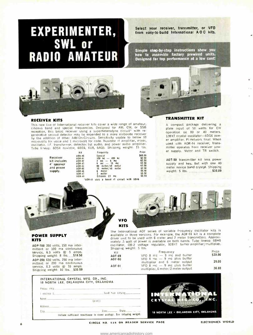
RECEIVER KITS This new line of International receiver kits cover a wide range of amateur, citizens band and special frequencies. Designed for AM, CW, or SSB
reception, this basic receiver using a superheterodyne circuit* with re-
generative second detector may be expanded to a more elaborate receiver by the addition of other Add -On- Circuits. Sensitivity usable to below 10
microvolts for voice and 1 microvolt for code. Nuvistor rf amplifier, mixer, oscillator, I.F. transformer, detector /1st audio, and power audio amplifier. Tube lineup: 6DS4 nuvistor, 6BE6, 6U8, 6AQ5. Shipping weight: 15 lbs.
Receiver kit includes 4" speaker and power supply.
Kit Frequency
AOR -40 Special AOR -41 150 kc - 450 kc
AOR -42 2 me - 6 me AOR -43 6 me - 18 me
AOR -44 B0 meter /40 meter AOR -45 15 meter /10 meter AOR -46 6 meter AOR -41 2 meter AOR -48 Citizens 21 me
-AOR -41 uses a tuned rf circuit with 6BA6
6
POWER SUPPLY KITS AOP -100 350 volts, 150 ma inter- mittent or 100 ma continuous service, 6.3 volts @ 5 amps. Shipping weight: 8 lbs. $18.50 AOP -200 650 volts, 250 ma inter- mittent or 200 ma continuous service, 6.3 volts @ 10 amps. Shipping weight: 10 lbs. $32.50
VFO KITS
The International AOF series of variable frequency oscillator kits is
available in three versions. For example, the AOF -91 kit is a complete driver unit to be used with 6 meter and 2 meter transmitters. Approxi- mately .5 watt of power is available on both bands. Tube lineup: 6BH6
oscillator, OB -2 voltage regulator, 12BY7 buffer -amplifier/multiplier. Shipping weight: 5 lbs.
Kit Frequency AOF -89 VFO 8 n-c - 9 me and buffer AOF -90 VFO 8 me - 9 me plus buffer
multiplier and 6 meter output AOF -91 VFO 8 me - 9 me plus buffer
multiplier, 6 meter /2 meter output
Price
569.00 62.50 62.50 62.50 62.50 62.50 66.50 66.50 62.50
TRANSMITTER KIT
A compact package delivering a
plate input of 50 watts for CW
operation on 80 or 40 meters. 12BY7 crystal oscillator -6DQ6 pow- er amplifier. Pi- network final. When used with AOR -44 receiver, trans- mitter operates from receiver pow- er supply. Meter and TR switch.
AOT -50 transmitter kit less power supply and key, but with one 40
meter novice band crystal. Shipping weight: 5 lbs. $35.00
INTERNATIONAL CRYSTAL MFG. CO., INC. 18 NORTH LEE, OKLAHOMA CITY, OKLAHOMA
Please ship.
I enclose S_
Name
Send free catalog
Address- - - -- City - - _
Zone _ State
Include sufficient remittance to cover postage. See shipping weight.
Price $22.00
29.00
36.00
18 NORTH LEE OKLAHOMA CITY, OKLAHOMA
CIRCLE NO. 128 ON READER SERVICE PAGE ELECTRONICS WORLD
www.americanradiohistory.com
WHAT IS THE COMMON DENOMINATOR OF AN ANCIENT EGYPTIAN PYRAMID AND A SUCCESSFUL MODERN ELECTRONICS CAREER?
A STRONG FOUNDATION! The Egyptian pyramid was built on a strong foundation. What about your electronics career ?
Advancement in electronics depends on a solid understanding of basic principles. If you are handicapped by a poor understanding of these vital "basics," you need training -the strong foundation training offered by Grantham School of Electronics. Beginning at the beginning, Grantham training progresses in a logical, step -by -step manner up through the complex theory of the Missile Age -and all of the math you will need is taught as an integral part of our lessons. Because we represent these all- important basic principles with maximum penetration, you will learn to think and reason electronics rather than relying on half- understood concepts and rote -memory. The Grantham program is made up of three consecutive steps, and each completed step increases your value as an electronics man. The following is a "thumb -nail sketch" of the Grantham 3 -step program for electronics advancement: A Section IA leads to attainment of your First Class FCC License and may be completed in
the classroom or through home study. Section IB gives you practical experience on a great variety of "live" electronics equipment in four weeks of intensive, supervised training in the Grantham Student Laboratory.
AiL Section II offers Advanced Electronics Training through home study and is designed to assure your advancement after you are on- the -job.
The above program may be taken as a whole, or you may complete only that step which best suits your individual needs !
To obtain full details on Grantham training, fill out and -Mail in envelope or paste on portal cord mail the coupon on the right. We will be glad to send you (without charge or obligation) our free 44 -page booklet, CAREERS IN ELECTRONICS.
GRANTHAM SCHOOL OF ELECTRONICS
c FIVE CONVENIENT TRAINING DIVISIONS: ''awe erg°,
1505 N. Western Ave., Los Angeles, Calif., 90021 HO 7.7727 9320 Long Beach Blvd., South Gate, Calif., 90280 564 -3421 408 Marion Street, Seattle, Wash., 98104 MA 2 -7227 3123 Gillham Rd., Kansas City, Mo., 64109 JE 1 -6320 821 -19th Street, NW, Washington, D.C., 20006 ST 3-3614
To: GRANTHAM SCHOOL OF ELECTRONICS NATIONAL HEADQUARTERS OFFICE
1505 N. WESTERN AVE., LOS ANGELES, CALIF., 90027
Please send me your FREE 44 -page booklet, "CAREERS IN ELECTRONICS."
Name
Address
City
(PLEASE PRINT) Age
State
I AM INTERESTED IN: HOME STUDY RESIDENT CLASSES 36S J
November, 1963 7
www.americanradiohistory.com
Exclusive with RCA ...
the faster, easier way toward a career in electronics
Amazing home training method makes learning almost automatic
Exclusive with RCA. " AUTOTEXT" the revolutionary home
training method introduced by RCA Institutes, Inc., is stir- ring the interest of thousands. Every day, "AUTOTEXT" is
helping people like yourself join the thousands of other suc-
cessful electronic students who are working toward profit- able careers right now This faster, easier way to learn elec-
tronics uses the latest scientific development in the field of
home training -and "AUTOTEXT" is exclusive with RCA.
Tested throughout the country. This exciting new trend in
education represents a significant advance in teaching electronics. People who have been interested in careers in
electronics in the past, but have had difficulty with conven-
tional home training methods, can now begin to master the fundamental principles of electronics almost automatically. Tested in schools throughout the country, checked out and
proved with thousands of students, programmed instruction is helping people learn more quickly and with less effort.
Prove it to yourself now! If you have a natural inclination or interest in the exciting field of electronics, that's all
you need. RCA " AUTOTEXT" will help you do the rest.
8
And the future is unlimited. Jobs are available for qualified technicians in Space Electronics, Communications, TV,
Computer Programming, Automation, and many other elec-
tronic fields. The important thing is to get started now!
Complete course available. Right now, RCA Institutes offers
you a complete Home Training Course ( "Introduction to
Electronics ") using the "AUTOTEXT" method. You get a
complete set of theory lessons, service practice lessons,
experiment lessons, and all the kits you need. And most im-
portant, " AUTOTEXT" takes most of the effort out of learn-
ing the all- important groundwork of the electronics field.
FREE OFFER! Well send you complete in-
formation on amazing new RCA "Autotext" along
with a FREE SAMPLE of a lesson to prove to you how
easy it is to learn this new way. Send the attached
postage-paid card and check "Autotext ".
ELECTRONICS WORLD
www.americanradiohistory.com
November, 1963
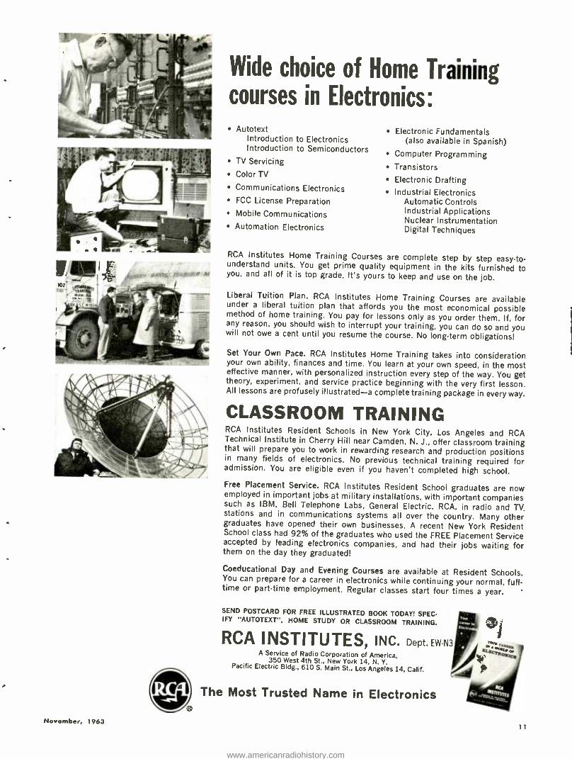
Wide choice of Home Training courses in Electronics:
Autotext Introduction to Electronics Introduction to Semiconductors
TV Servicing
Color TV
Communications Electronics FCC License Preparation
Mobile Communications
Automation Electronics
Eiectronic Fundamentals (also available in Spanish)
Computer Programming
Transistors
Electronic Drafting Industrial Electronics
Automatic Controls Industrial Applications Nuclear Instrumentation Digital Techniques
RCA Institutes Home Training Courses are complete step by step easy-to- understand units. You get prime quality equipment in the kits furnished to you, and all of it is top grade. It's yours to keep and use on the job.
Liberal Tuition Plan. RCA Institutes Home Training Courses are available under a liberal tuition plan that affords you the most economical possible method of home training. You pay for lessons only as you order them. If, for any reason, you should wish to interrupt your training, you can do so and you will not owe a cent until you resume the course. No long -term obligations!
Set Your Own Pace. RCA Institutes Home Training takes into consideration your own ability, finances and time. You learn at your own speed, in the most effective manner, with personalized instruction every step of the way. You get theory, experiment, and service practice beginning with the very first lesson. All lessons are profusely illustrated -a complete training package in every way.
CLASSROOM TRAINING RCA Institutes Resident Schools in New York City, Los Angeles and RCA Technical Institute in Cherry Hill near Camden, N. J., offer classroom training that will prepare you to work in rewarding research and production positions in many fields of electronics. No previous technical training required for admission. You are eligible even if you haven't completed high school.
Free Placement Service. RCA Institutes Resident School graduates are now employed in important jobs at military installations, with important companies such as IBM, Bell Telephone Labs, General Electric, RCA, in radio and TV. stations and in communications systems all over the country. Many other graduates have opened their own businesses. A recent New York Resident School class had 92% of the graduates who used the FREE Placement Service accepted by leading electronics companies, and had their jobs waiting for them on the day they graduated!
Coeducational Day and Evening Courses are available at Resident Schools. You can prepare for a career in electronics while continuing your normal, full- time or part -time employment. Regular classes start four times a year.
SEND POSTCARD FOR FREE ILLUSTRATED BO OK TODAY! SPEC- IFY "AUTOTEXT ", HOME STUDY OR CLASSROOM TRAINING. e RCA INSTITUTES, INC. Dept.EW -N3 ,.m
41 A Service of Radio Corporation of America,
350 West 4th St., New York 14 N Y. Pacific Electric Bldg., 610 S. Main St., Los Angeles 14, Calif.
The Most Trusted Name in Electronics
11
www.americanradiohistory.com
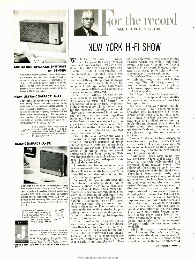
MINIATURE SPEAKER SYSTEMS BY JENSEN
Here are two Jensen speakers capable of the sound
you'd expect from much larger units. Perfect far
economical stereo extension ... compact stereo
hi -fi ... FM Multiplex stereo. Place them on any
surface, or hang them on the wall. Both feature
Jensen's custom two -tone grille fabrics. Write for
Brochure MX for full details.
NEW ULTRA -COMPACT X -11
2- speaker 2 -way system. A special woofer with a
new moving system precisely matched to its
diminutive enclosure is largely responsible for the
truly remarkable performance of the X -11. A 3' tweeter extends high frequency response to 14,000
cycles. Improved efficiency gives full room volume
with amplifiers of low power rating. Volume is
adjustable by a control on the side of the cabinet.
Dimensions: 6s /g' H, l3rr /ó' W, 4' D.
X -11 2- speaker 2 -way system. May be
used with amplifiers having 4, 8. or 16
ohm output. Power rating 6 watts. Ade- quate room sound with 1 watt to speaker. In oiled walnut $29.75
SLIM -COMPACT X -20
a
3- speaker 2 -way system. Unbelievably excellent
sound quality is yours from Jensen's famous X -20
speaker system. A specially designed woofer with
powerful SYNTOX-6® magnet, plus two tweeters provide smooth, wide -range sound. Extra slim ... perfect for wall mounting. Side control allows vol-
ume adjustment. Dimensions: 127/' H, IS %' W,
2%' D.
X-20 3-speaker 2 -way system. May be used with amplifiers having 4,
8. or 16 ohm output. Power rating 6 watts. Adequate room sound
with I watt to speaker. In oiled walnut $39.95
J I N S E N
1011DSPIAxIPS
JENSEN MANUFACTURING COMPANY Division of THE MUTER COMPANY
6601 S. Laramie Ave., Chicago 38, 1111nois
Canada' Radio Speakers of Canada, Ltd, Toronto Argentina' UCOA. S. A., Buenos Aires Mexico: Faparlel, S. A., Naucalpan, Mea.
CIRCLE NO. 129 ON READER SERVICE PAGE 12
o the record WM. A. STOCKLIN, EDITOR
NEW YORK HI -FI SHOW
`N, -ITH the New York Hi -Fi Show v over, it appears that once again we
have had an exciting, well- attended show. This is the eighth consecutive year that the Institute of High Fidelity, Inc. has planned and operated these shows and this year's show surpassed all previ- ous ones. Although the purpose is always the same -to serve as a showcase for component hi -fi equipment -each year's displays, room settings, and components become more sophisticated.
Even those attending the Show seemed to have changed. In the early days, when the term "hi -fi" carried the connotation of some strange, mysterious audio system, those who attended were, for the most part, technically oriented. They were more interested in circuit de- sign and unusual sound recordings than in styling. But now technically oriented enthusiasts, as well as many others who are not circuit -minded, seem more inter- ested in the realism of sound reproduc- tion. This is as it should be, and this year's Show concurred.
One of the main attractions was a "live -vs- recording" demonstration in which a four -piece instrumental group played specially composed music both in person and via tape. The public was asked to determine when one sound source took over from the other. This was the first time that such a large audi- ence had a chance to participate in this kind of demonstration.
A greater number of manufacturers was represented this year than at past Shows. This can be attributed to greater competition and diversification on the part of many companies.
As usual, the public attended the Show to see the new products, talk to engineers about their audio problems, and, in general, learn about recent im- provements in sound reproduction. They were not disappointed. Although there have been no major breakthroughs-com - parable to the stereo disc or FM- stereo of previous years -there were changes, most of them subtle. The manufacturers have made tremendous strides in pro- viding more attractive panel designs and cabinets while retaining high -quality sound reproduction.
Tape Recorders: In this category there were many more new products to choose from than heretofore and the quality of reproduction at 3% ips was far superior to that offered by last year's equipment. Even at 1% ips, in the more expensive recorders, performance came close to that of early 7'í -ips units. Revere -Wollen-
sak (3M) showed its new tape cartridge recorder which was widely publicized several years ago. Although it will never replace the disc record changer, it repre- sents a new design philosophy and a new convenience in tape equipment.
Turntables: There were several new and different designs, most with higher price tags. The older designs were of- fered in revised versions with emphasis on improved appearance and better re- production quality.
Cartridges: Not much change was ex- pected in this component since quality of reproduction on almost all units has been quite high.
Speakers: There were many new de- signs displayed - but, again, no major breakthroughs. Improvements in sound reproduction were evident in a good many units. Speakers are peculiar in a way since it is difficult to outline any single design element that makes for better sound. Yet, comparing today's speakers with those of ten years ago, or even five years ago, the improvement is obvious.
Tuners: Most manufacturers displayed new designs or up -dated versions of last year's models. The emphasis was on stereo and on transistorization, with con- siderable improvement in performance over last year's models.
Amplifiers: There were many new transistorized designs, and it was in this area that the technically minded hi -fi enthusiast found greatest interest. The subject of tubes vs transistors is the most controversial one in the hi -fi field today. There have been no major design inno- vations since last year's Show, but almost all manufacturers have been concentrat- ing their engineering efforts on transis- torized designs. Although engineers still disagree on many points, such as the importance of square -wave response, damping factor, amount of IM and har- monic distortion, necessary frequency response, use of output transformers, and phase distortion, they all seem to agree that the semiconductor designs have tre- mendous possibilities in the near future. There were many such designs in evi- dence at the Show, and a few of them were exceptionally good - to the point where one might say they compared favorably with the best tube designs available.
All in all, it was a tremendous Show and, like many others who had the op- portunity to attend, we look forward to what the coming year will bring in the way of new and better iii -fi egf1ilm1ent.
ELECTRONICS WORLD
www.americanradiohistory.com
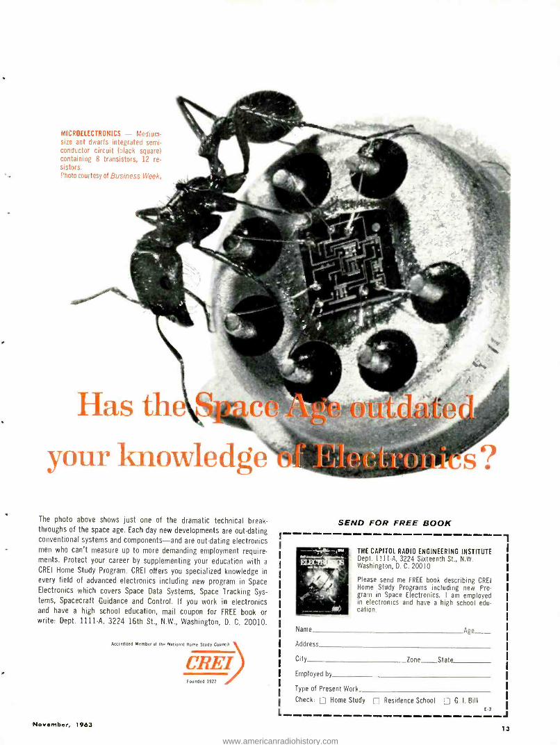
MICROELECTRONICS - Medium - size ant dwarfs integrated semi- conductor circuit (black square) containing 8 transistors, 12 re- sistors. Photo courtesy of Business Week.
Has th your knowledg
The photo above shows just one of the dramatic technical break- throughs of the space age. Each day new developments are out -dating conventional systems and components -and are out -dating electronics men who can't measure up to more demanding employment require- ments. Protect your career by supplementing your education with a
CREI Home Study Program. CREI offers you specialized knowledge in every field of advanced electronics including new program in Space Electronics which covers Space Data Systems, Space Tracking Sys- tems, Spacecraft Guidance and Control. If you work in electronics and have a high school education, mail coupon for FREE book or write: Dept. 1111 -A, 3224 16th St., N.W., Washington, D. C. 20010.
November, 1963
Accredited Member or the National Home Study Council
CREI Founded
SEND FOR FREE BOOK
THE CAPITOL RADIO ENGINEERING INSTITUTE Dept. 1111 -A, 3224 Sixteenth St.. N.W. Washington, D. C. 20010
Please send me FREE book describing CREI Home Study Programs including new Pro- gram in Space Electronics. I am employed in electronics and have a high school edu- cation.
Name Age
Address
City Zone State
Employed by
Type of Present Work
Check: Home Study Residence School G. I. Bill L E3
Ì
.1
13
www.americanradiohistory.com
A REVOLUTIONARY NEW
METHOD FOR MARKING
ELECTRONIC EQUIPMENT
KILOWATTS
LEA LEFT L LEVELING LIMIT LIMIT LIMITERS LI
IMITING LINE EARITY LIN EARITY LIN EAR LINEAR
NKAGfFc s efi
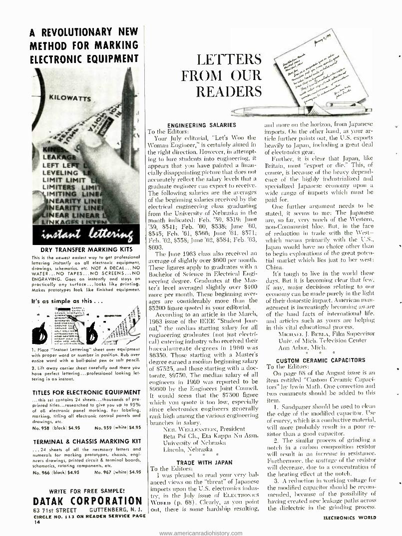
ú,ß.Z tai/14i DRY TRANSFER MARKING KITS
This is the newest easiest way to get professional lettering instantly on all electronic equipment, drawings, schematics, etc. NOT A DECAL ...NO WATER...NO TAPES...NO SCREENS...NO ENGRAVING. Goes on instantly and stays on
practically any surface...looks like printing. Makes prototypes look like finished equipment.
It's as simple as this ...
1. Place "Instant lettering" sheet over equipment with proper word or number in position. Rub over entire word with a ball -point pen or soft pencil.
2. lift away carrier sheet carefully and there you have perfect lettering...professional looking let. tering in an instant.
TITLES FOR ELECTRONIC EQUIPMENT ...this set contains 24 sheets...thousands of pre- printed titles...researched to give you up to 95% of all electronic panel marking. For labeling, marking, titling all electronic control panels and drawings, etc.
No. 958 (block) $4.95 No.959 (white) $4.95
TERMINAL & CHASSIS MARKING KIT
...24 sheets of all the necessary letters and numerals for marking prototypes, chassis, engi- neers drawings, printed circuit & terminal boards, schematics, rotating components, etc.
No. 966 (black) $4.95 No. 967 (white) $4.95
WRITE FOR FREE SAMPLE!
DATAK CORPORATION 63 71st STREET GUTTENBERG, N. J.
CIRCLE NO. 113 ON READER SERVICE PAGE 14
LETTERS FROM OUR
READERS
ENGINEERING SALARIES To the Editors:
Your July editorial, "Let's Woo the Woman Engineer," is certainly aimed in
the right direction. However, in attempt- ing to lure students into engineering, it appears that you have painted a finan- daily disappointing picture that does not accurately reflect the salary levels that a graduate engineer can expect to receive. The following salaries are the averages of the beginning salaries received by the electrical engineering class graduating from the University of Nebraska in the month indicated: Feb. '59, $519; June '59, $541; Feb. '60, $538; June '60, $545; Feb. '61, $566; June '61. $571; Feb. '62, $558; June '62, $584; Feb. '63, $603.
The June 1963 class also received an average of slightly over $600 per month. These figures apply to graduates with a
Bachelor of Science in Electrical Engi- neering degree. Graduates at the Mas- ter's level averaged slightly over $100 more per month. These beginning aver- ages are considerably more than the $5200 figure quoted in your editorial.
According to an article in the March, 1963 issue of the IEEE "Student Jour- nal," the median starting salary for all engineering graduates ( not just electri- cal) entering industry who received their baccalaureate degrees in 1960 was 86350. Those starting with a Master's degree earned a median beginning salary of $7525, and those starting with a doc- torate, $9750. The median salary of all engineers in 1960 was reported to be 89600 by the Engineers Joint Council. It would seem that the $7500 figure which you quote is too low, especially since electronics engineers generally rank high among the various engineering branches in salary.
NEIL \\'ELLEXSTEIN, President Beta Psi Ch., Eta kappa Nu Assn. University of Nebraska Lincoln, Nebraska
o e e
TRADE WITH JAPAN To the Editors:
I was pleased to read your very bal- anced views on the "threat" of Japanese imports upon the U.S. electronics indus- try, in the July issue of ELECTRONICS
WORLD (p. 68). Clearly, as you point out, there is some hardship resulting,
and more on the horizon, from Japanese imports. On the other hand, as your ar- ticle further points out, the U.S. exports heavily to Japan, including a great deal of electronics gear.
Further, it is clear that Japan, like Britain, must "export or die." This, of course, is because of the heavy depend- ence of the highly industrialized and specialized Japanese economy upon a wide range of imports which must be paid for.
One further argument needs to be stated, it seems to me: The Japanese are, so far, very much of the Western, non -Communist bloc. But, in the face of reduction in trade with the West - which means primarily with the U.S., Japan would have no choice other than to begin explorations of the great poten- tial market which lies just to her \vest: China.
It's tough to live in the world these days. But it is becoming clear that few, if any, major decisions relating to our economy can be made purely in the light of their domestic impact. American man- agement is increasingly becoming aware of the hard facts of international life. and articles such as yours are helping in this vital educational process.
MI(.IIAE!. J. BERi.A, Film Supervisor Univ. of Mich. Television Center Ann Arbor. Mich.
e a o
CUSTOM CERAMIC CAPACITORS To the Editors:
On page (f8 of the August issue is an item entitled "Custom Ceramic Capaci- tors" by Irvin Math. One correction and two comments should be added to this item.
1. Sandpaper should be used to clean the edge of the modified capacitor. Use of emery, which is a conductive material, \rill more probably result in a poor re- sistor than a good capacitor.
2. The similar process of grinding a notch in a carbon composition resistor will result in an increase in resistance. Furthermore, the wattage of the resistor will decrease. due to a concentration of the heating effect at the notch.
3. A reduction in working voltage for the modified capacitor should be recom- mended, because of the possibility of having created new leakage paths across the dielectric in the grinding process.
ELECTRONICS WORLD
www.americanradiohistory.com
See Only the Scale You Want. .. in the Exact Range You Want /.00
just set the range switch
and the correct scale appears AUTOMATICALLY
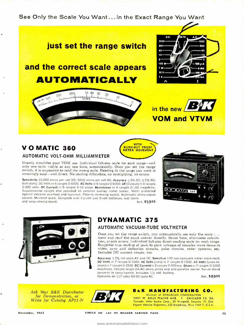
V O MATIC 360 AUTOMATIC VOLT -OHM MILLIAMMETER Greatly simplifies your VOM use. Individual full -size scale for each range -and only one scale visible at any one time, automatically. Once you set the range switch, it is impossible to read the wrong scale. Reading in the range you want is amazingly easy -and direct. No reading difficulties, no multiplying, no errors. Sensitivity 20,000 ohms per volt DC; 5000 ohms per volt AC. Accuracy ±3 %a DC; ±5 %a AC; (full scale). DC Volts in 6 ranges 0.6000. AC Volts in 6 ranges 0 -6000. AF (Output) in 4 ranges 0.300 volts. DC Current in 5 ranges 0 -10 amps. Resistance in 4 ranges 0 -100 megohms. Supplemental ranges also provided on external overlay meter scales. Meter protected against extreme overload and burn -out. Polarity reversing switch. Automatic ohms -adjust control. Mirrored scale. Complete with 11/2-volt and 9 -volt batteries, test leads, and easy- viewing stand. Net, $5995
in the new
VOM and VTVM
DYNAMATIC 375 AUTOMATIC VACUUM -TUBE VOLTMETER
Once you set the range switch, you automatically see only the scale .4 want and read the exact answer directly. Saves time, eliminates calcula- tion, avoids errors. Individual full -size direct -reading scale for each range. Simplifies true reading of peak -to -peak voltages of complex wave forms in video, sync and deflection circuits, pulse circuits, radar systems, etc. Includes DC current ranges, too.
Accuracy ±3 %a full scale AC and DC. Sensitive 100 microampere meter movement. DC Volts in 7 ranges 0 -1500. AC Volts (rms) in 7 ranges 0 -1500. AC Volts (peak -to- peak) in 7 ranges 0-1500. DC Current in 3 ranges 0-500 ma. Ohms in 7 ranges 0-1000 megohms. Utilizes single DA -AC ohms probe and anti -parallax mirror. Swivel stand converts to carry -handle. Includes 11/2 volt battery. Operates on 117 volts 50-60 cycle AC. Net, $8995
Ask Thar B &K Distributor for Demonstration, or
Write for Catalog AP21-N
Ba K MANUFACTURING CO. Division of DYNASCAN CORPORATION
1801 W. BELLE PLAINE AVE. CHICAGO 13, ILL. Canada: Atlas Radio Corp., 50 Wingold, Toronto 19, Ont. Export: Empire Exporters, 253 Broadway, New York 7, U.S.A.
November, 1963 CIRCLE NO. 105 ON READER SERVICE PAGE 15
www.americanradiohistory.com
MOST EXCITING AUTOMOTIVE
DEVELOPMENT IN 50 YEARS!
AEC AFÇ7777 TRANSISTOR IGNITION SYSTEMS
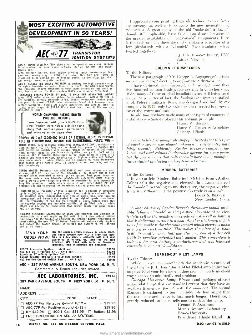
AEC77 TRANSISTOR IGNITION gives a hot fast spark at every plug, because it eliminates the area where ordinary ignition systems lose power. Here's how: - With ordinary ignition, slow engine cranking sends breaker -point tem- peratures soaring - up to 2000° F or more. This high heat forms an insulating oxide coating on the breaker points, so the plugs just don't get enough power to ignite the fuel. AEC77 SOLVES THE WHOLE PROBLEM by pushing the high current charge through a transistor instead of through the points. The points just trigger the transistor. They're subjected to much lower current so they don't get hot, don't coat up. It's that simple - that's why it works every time.
INCREASED ENGINE POWER BY 10% IS ONLY ONE ADVANTAGE. AEC -77 gives 15% extra miles per gallon, faster warmups, instant starting in any weather, permits smoother idling, boosts horsepower, makes plugs and points last over 75,000 miles, eliminates 3 out of 4 tune -ups, com- pletely waterproof, simple 20 minute installation, and pays for itself in 10,000 miles usage. At $39.95 it's a real buy . , . and it fits any car. domestic or import.
1 WORLD CHAMPION RACING DRIVER
PHIL HILL REPORTS
I was impressed with your AEC -77 iron sistor Ignition. Rarely does a device come along that improves power, performance and economy at the some time
PROVEN IN OVER 2,000,000 MILES OF TESTING, AEC -77 IS DEPEND-
ABLE IN PERFORMANCE, DESIGN AND ENGINEERING. HERE'S WHY: - TRANSISTORS: General Motors Delco type -2N1358A -1100A transistors are used in every AEC 77. They are the finest high power 15 ampere 150 watt transistors available with voltage ratings in excess of 100 volts. Peak current loads in any transistor ignition can go as high as 15
amperes. AEC 77 handles these peak current loads safely by using a 15
ampere 150 watt transistor, assuring you of high reliability and depend- able performance ... while others use 10 ampere 90 watt transistors that cannot safely handle these 15 ampere current overloads, and can fail prematurely.
ZENER DIODES: Motorola type 1N2836B 50 watt zener diodes are usen in every AEC 77. They protect the transistors from failure due to high voltage spikes generated in every ignition system. Peak power loads on the zener diode in any transistor ignition can exceed 25 watts. AEC 77 uses a 50 watt zener diode to protect the transistor for safe dependable long life operation ... while others use a 10 watt zener diode that can overheat and fail to protect the transistor, causing premature failure.
IGNITION COIL: Transistor 77 (400:1) ignition coil is capable of producing up to 40,000 volts at all engine speeds. Every coil is wound with Form - var insulated wire, impregnated first with an epoxy resin, and then oil impregnated and hermetically sealed in the highest grade transformer oil. The Transistor 77 coil has the strength of epoxy molded coils plus the superior cooling and insulative qualities of oil filled coils ... while others use inferior tar filled coils that cannot handle the power loads AEC 77 delivers.
BALLAST RESISTOR: Constructed of space age ceramics and virtually in- destructible, is a self regulating 250 watt .3 to .9 ohm ballast resistor that saves you the trouble of adjusting the breaker points. Regardless of point setting, the new AEC 77 Ballast Resistor will automatically regulate and supply the proper amount of voltage and current to the ignition coil at all times.
SEND YOUR ORDER NOW!
Use the coupon, attach a check or money order, and you'll receive your AEC -77 Transistor Igni- tion in a few days ... complete with a 3 year guarantee in writing. Or, send for the free brochure, it's filled with facts on transistor ignitions, their installation and operation.
AEC -77 Transistor Ignition ... 6/12 volt AEC K -4 Do It Yourself Kit ... 6 /12 volt Transistor 77 (400:1) Ignition Coil Ballast Resistor, 250 watt .3 to .9 ohm, variable AEC Positive Ground (British Cars) ... 6/12 volt
$39.95 $32.95 $11.95 $1.95
$39.95
AEC 387 PARK AVENUE SOUTH, NEW YORK 16, N. Y.
Commercial & Dealer Inquiries Invited
AEC LABORATORIES, INC. 387 PARK AVENUE SOUTH NEW YORK 16
EW113
N. Y.
NAME
ADDRESS
CITY ZONE STATE
AEC -77 For Negative ground 6/12 v . $39.95 AEC -77P For Positive ground 6/12 v $39.95 Kit $32.95 400:1 Coil $11.95 C Ballast $1.95 FREE BROCHURE ON AEC 77 SYSTEMS.
16 CIRCLE NO. 104 ON READER SERVICE PAGE
I appreciate your printing these old techniques to refresh my memory, as well as to educate the new generation of technicians. A great many of the old "make -do" tricks, al- though still applicable, have fallen into disuse because of the greater availability of "ready- made" components. Rare is the tech or ham these days who makes a capacitor of a few picofarards with a "gimmick" (two insulated wires twisted together).
Lt. Cdr. R0RE11T IRVING, USN Fairfax, Virginia
0 0 0
COLUMN LOUDSPEAKERS
To the Editors: The first paragraph of Mr. George L. Augspurger's article
on column loudspeakers in your June issue disturbs me. I have designed, manufactured, and installed more than
five hundred column loudspeaker systems in churches since 1938; many of these original installations are still being used today. As a matter of fact, the loudspeaker system installed in St. Peter's Basilica in Rome was designed and built by my company in 1947; only two columns were needed to properly cover the entire auditorium.
In addition. we have made many other types of commercial installations which employed this column principle.
HARRY W. BECKER Harry W. Becker & Associates Chicago, Illinois
The artic'le's first paragraph .simply indicated that this type of speaker system was almost unknown in this country until fairly recently. Evidently, Reader Becker's company has knoten and used column loudspeaker .systems for many years, but the fact remains that only recently have many manufac- turers.started producing such systems.- Editors.
MODERN BATTERIES
To the Editors: In your article "Modern Batteries" (October issue), Author
Collins calls the negative zinc electrode in a Leclanche cell the "anode." According to my dictionary, the negative elec- trode is a cathode and the positive electrode is an anode.
JAMES S. BEAVER New London, Conn.
A later edition of Reader Beaver's dictionary would prob- ably define an "anode" as the positive electrode of an elec- trolytic cell or the negative electrode of a dry cell or battery that is delivering current to a load. Another dictionary defini- tion of an anode is the electrode toward which electrons move in a cell or electron tube. This makes the plate of a diode (with its positive potential) and the zinc can of a dry cell (with its negative potential) both anodes. This convention is followed by most battery manufacturers and was followed correctly in our article.- Editors.
BURNED -OUT PILOT LAMPS To the Editors:
While I have no quarrel with the academic accuracy of the article by R. L. Ives "Burned -Out Pilot -Lamp Indicators" on page 40 of your June issue, it does seem an overly involved way to solve an admittedly real problem.
Chicago Miniature Lamp Works (and perhaps others) make pilot lamps that are standard except that they have an auxiliary filament in parallel with the main one. The second filament is designed to burn considerably less bright than the main one and hence to last much longer. Therefore, a greatly reduced brilliance tells one to replace the lamp.
GEORGE P. ANDERSON Metals Research Laboratory Brown University Providence, Rhode Island
ELECTRONICS WORLD
www.americanradiohistory.com
READER SERVICE PAGE
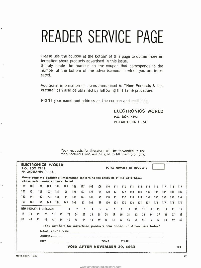
Please use the coupon at the bottom of this page to obtain more in- formation about products advertised in this issue. Simply circle the number on the coupon that corresponds to the number at the bottom of the advertisement in which you are inter- ested.
Additional information on items mentioned in "New Products & Lit- erature" can also be obtained by foll owing this same procedure.
PRINT your name and address on the coupon and mail it to:
ELECTRONICS WORLD P.O. BOX 7842
PHILADELPHIA 1, PA.
Your requests for literature will be forwarded to the manufacturers who will be glad to fill them promptly.
ELECTRONICS WORLD P.O. BOX 7842 PHILADELPHIA 1, PA.
TOTAL NUMBER OF REQUESTS
Please send me additional information concerning the products of the advertisers whose code numbers I have circled.
100 101 102 103 104 105 106 107 108 109 110 111 112 113 114 115 116 117 118 119
120 121 122 123 124 125 126 127 128 129 130 131 132 133 134 135 136 137 138 139
140 141 142 143 144 145 146 147 148 149 150 151 152 153 154 155 156 157 158 159
160 161 162 163 164 165 166 167 168 169 170 171 172 173 174 175 176 177 178 179
NEW PRODUCTS & LITERATURE 1 2 3 4 5 6 7 8 9 10 11 12 13 14 15 16
17 18 19 20 21 22 23 24 25 26 27 28 29 30 31 32 33 34 35 36 37 38
39 40 41 42 43 44 45 46 47 48 49 50 51 52 53 54 55 56 57 58 59 60
(Key numbers for advertised products also appear in Advertisers Index) NAME 'PRINT CLEARLY
ADDRESS
CITY ZONE STATE
VOID AFTER NOVEMBER 30, 1963 11
November, 1963 17
www.americanradiohistory.com
WIHNrisk your reputation
with 'just -as- good" capacitors? When you pay little or no attention to quality in tubular replacement capacitors, you leave yourself wide open for criticism of your work ... you risk your reputation ... you stand to lose customers. It just doesn't pay to take a
chance on capacitors with unknown or debatable performance records when it's so easy to get guaranteed dependable tubulars from your Sprague distributor!
There's no "maybe'
with these 2 great
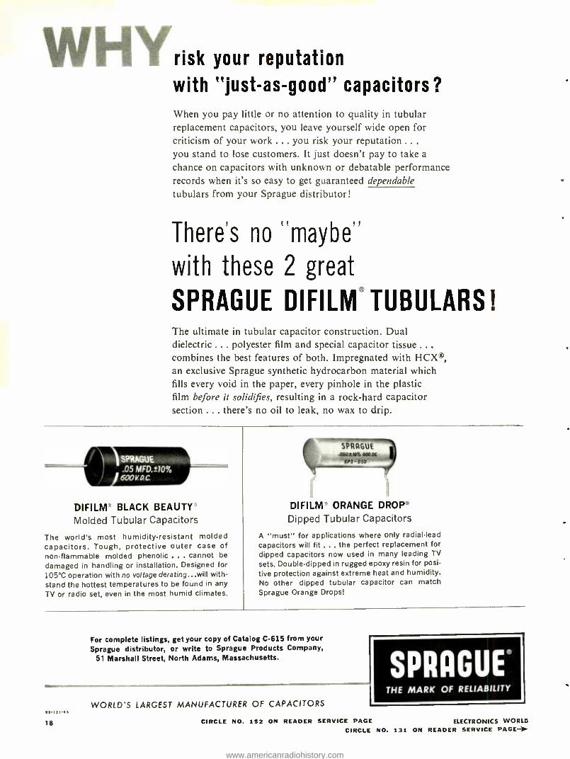
SPRAGUE DIFILM TUBULARS! The ultimate in tubular capacitor construction. Dual dielectric ... polyester film and special capacitor tissue ... combines the best features of both. Impregnated with HCX ,
an exclusive Sprague synthetic hydrocarbon material which fills every void in the paper, every pinhole in the plastic film before it solidifies, resulting in a rock -hard capacitor section ... there's no oil to leak, no wax to drip.
DIFILM BLACK BEAUTY Molded Tubular Capacitors
The world's most humidity-resistant molded capacitors. Tough, protective outer case of nonflammable molded phenolic ... cannot be
damaged in handling or installation. Designed for 105 °C operation with no voltage derating...will with- stand the hottest temperatures to be found in any TV or radio set, even in the most humid climates.
{f121.1]
18
DIFILM' ORANGE DROP' Dipped Tubular Capacitors
A "must" for applications where only radial-lead capacitors will fit ... the perfect replacement for dipped capacitors now used in many leading TV
sets. Double-dipped in rugged epoxy resin for posi-
tive protection against extreme heat and humidity. No other dipped tubular capacitor can match Sprague Orange Drops!
For complete listings, get your copy of Catalog C -615 from your Sprague distributor, or write to Sprague Products Company,
51 Marshall Street, North Adams, Massachusetts.
WORLD'S LARGEST MANUFACTURER OF CAPACITORS
SPRAGUE® THE MARK OF RELIABILITY
CIRCLE NO. 152 ON READER SERVICE PAGE ELECTRONICS WORLD CIRCLE NO. 131 ON READER SERVICE PAGE-
www.americanradiohistory.com
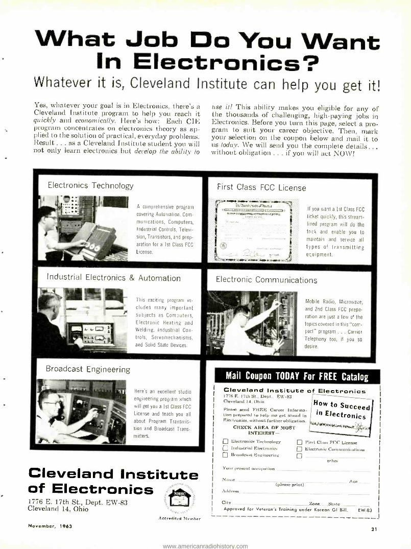
What Job Do You Want In Electronics?
Whatever it is, Cleveland Institute can help you get it! Yes, whatever your goal is in Electronics, there's a Cleveland Institute program to help you reach it quickly and economically. Here's how: Each CIE program concentrates on electronics theory as ap- plied to the solution of practical, everyday problems. Result ... as a Cleveland Institute student you will not only learn electronics but develop the ability to
Electronics Technology
AIM A comprehensive program
covering Automation. Com-
munications, Computers,
Industrial Controls, Televi-
sion, Transistors, and prep-
aration for a 1st Class FCC
License.
Industrial Electronics & Automation
use it! This ability makes you eligible for any of the thousands of challenging, high -paying jobs in Electronics. Before you turn this page, select a pro- gram to suit your career objective. Then, mark your selection on the coupon below and mail it to us today. We will send you the complete details ... without obligation ... if you will act NOW!
First Class FCC License
-r,,.:._..:.....:!ä..._.:. ch.:buA`M.0-.A dmaha
UM, ,,:,.n.,o.,:,,n:a.m,,,o,;,sn.
:t..e.;.m.:. ..:....r amt.....,.:.ti
If you want a 1st Class FCC
ticket quickly, this stream- lined program will do the
trick and enable you to maintain and service all types of transmitting equipment.
This exciting program in-
cludes many important subjects as Computers, Electronic Heating and Welding. Industrial Con-
trols, Servomechanisms,
and Solid State Devices.
Mobile Radio, Microwave,
and 2nd Class FCC prepa-
ration are just a few of the
topics covered in this "corr- pact" program ... Carrier
Telephony too, if you so
desire.
Broadcast Engineering
Here's an excellent studio
engineering program which
will get you a 1st Class FCC
License and teach you all
about Program Transmis-
sion and Broadcast Trans-
mitters.
Cleveland Institute of Electronics fel 1776 E. 17th St., Dept. EW -83 Cleveland 14, Ohio
:Accredited \lember
November, 1963
Mail Coupon TODAY For FREE Catalog
Cleveland Institute of Electronics 1776 E. 1711, St.. Dept. E \\' -83 Cleveland 14. Ohio
Please send FREE Career Informa- tion prepared to help me get ahead in Electronics. without further obligation.
CHECK AREA OF MOST INTEREST -
Electronics Technology Industrial Electronics Broadcast Engineering
Your present ,x-cupnl ion
Y:
Addres..s
How to Succeed in Electronics
First Class FCC License Electronic Communications
other
(please print) Acs
City Zone. Stade Approved for Veteran's Training under Korean GI Bill. EW -83
21
www.americanradiohistory.com
EW
LAB TESTED
HI-FI PRODUCT REPORT TESTED BY HIRSCHHOUCK LABS
"Acoustech I" Power Amplifier Audio Dynamics ADC -14 Speaker System
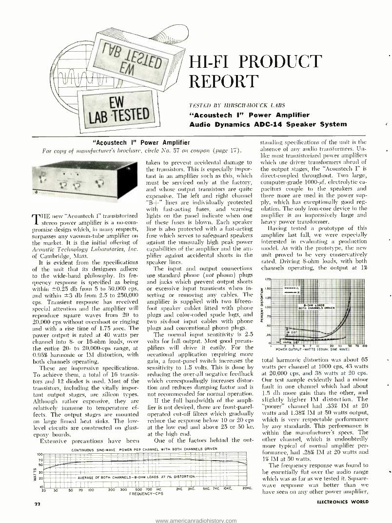
"Acoustech I" Power Amplifier For copy of manufacturer's brochure, circle No. 57 on coupon (page 17).
HE new "Acoustech I" transistorized 1 stereo power amplifier is a no -com-
promise design which, in many respects, surpasses any vacuum -tube amplifier on the market. It is the initial offering of Acoustic Technology Laboratories, Inc. of Cambridge, Mass.
It is evident from the specifications of the unit that its designers adhere to the wide -band philosophy. Its fre- quency response is specified as being within -0.25 db from 5 to 50,000 cps, and within ±3 db from 2.5 to 250,000 cps. Transient response has received special attention and the amplifier will reproduce square waves from 20 to 20,000 cps without overshoot or ringing and with a rise time of 1.75 µsec. The power output is rated at 40 watts per channel into 8- or 16 -ohm loads, over the entire 20- to 20,000 -cps range, at 0.95% harmonic or IM distortion, with both channels operating.
These are impressive specifications. To achieve them, a total of 16 transis- tors and 12 diodes is used. Most of the transistors, including the vitally impor- tant output stages, are silicon types. Although rather expensive, they are relatively immune to temperature ef- fects. The output stages are mounted on large finned heat sinks. The low - level circuits are constructed on glass - epoxy boards.
Extensive precautions have been
1
v, r
taken to prevent accidental damage to the transistors. This is especially impor- tant in an amplifier such as this, which must be serviced only at the factory, and whose output transistors are quite expensive. The left and right channel "B+" lines are individually protected with fast -acting fuses, and warning lights on the panel indicate when one of these fuses is blown. Each speaker line is also protected with a fast -acting fuse which serves to safeguard speakers against the unusually high peak power capabilities of the amplifier and the am- plifier against accidental shorts in the speaker lines.
The input and output connections use standard phone (not phono) plugs and jacks which prevent output shorts or excessive input transients when in- serting or removing any cables. The amplifier is supplied with two fifteen - foot speaker cables fitted with phone plugs and color -coded spade lugs, and two six -foot input cables with phone plugs and conventional phono plugs.
The normal input sensitivity is 2.5 volts for full output. Most good pream- plifiers will drive it easily. For the occasional application requiring more gain, a front -panel switch increases the sensitivity to 1.5 volts. This is done by reducing the over -all negative feedback which correspondingly increases distor- tion and reduces damping factor and is
not recommended for normal operation. If the full bandwidth of the ampli-
fier is not desired, there are front- panel- operated cut -off filters which gradually reduce the response below 10 or 20 cps at the low end and above 25 or 50 kc. at the high end.
One of the factors behind the out-
CONTINUOUS SINE-WAVE POWER PER CHANNEL WITH BOTH CHANNELS DRIVEN
O NNEN NIWINIMPIMNI 0_ . . `. . . . . . . . . _ M - ..Ear _..... ME= IO .....w..
!O . AVERAGE OF BOTH CHANNELS-8-OHM LOADS AT I. OISTORTION
ID I " ' ; ' ' `Il 1 f! 1I II 1 I I I 1
20 30
22
SO 70 100 200 300 FREQUENCY -CPS
C.
standing specifications of the unit is the absence of any audio transformers. Un- like most transistorized power amplifiers which use driver transformers ahead of the output stages, the "Acoustech I" is direct -coupled throughout. Two large, computer -grade 1000 -µf. electrolytic ca- pacitors couple to the speakers and three more are used in the power sup- ply, which has exceptionally good reg- ulation. The only iron -core device in the amplifier is an impressively large and heavy power transformer.
Having tested a prototype of this amplifier last fall, we were especially interested in evaluating a production model. As with the prototype, the new unit proved to be very conservatively rated. Driving 8 -ohm loads, with both channels operating, the output at 1%
I.7
1.70
1.27
z
á á
50
.25
o
11:immli'i11llR ir iig : :
! mill __._. -OHM OADS . MI:BOTH CHANNELS DRIVEN
:: ; AMR lirii1n API I. ol::::`-:Fä1:=:lllIl w da':
sT!e1 s:7w1 i uOmliii': 11: 2 3 5 7 10 20 70 50 70
POWER OUTPUT -WATTS (EOUIV. SINE WAVE) ao
total harmonic distortion was about 65 watts per channel at 1000 cps, 43 watts at 20,000 cps, and 38 watts at 20 cps. Our test sample evidently had a minor fault in one channel which had about 1.5 db more gain than the other, and slightly higher IM distortion. The "poorer" channel had .33% IM at 20 watts and 1.38% IM at 50 watts output, which is very respectable performance by any standards. This performance is within the manufacturer's specs. The other channel, which is undoubtedly more typical of normal amplifier per- formance, had .28% IM at 20 watts and 1% IM at 50 watts.
The frequency response was found to be essentially flat over the audio range which was as far as we tested it. Square - wave response was better than we have seen on any other power amplifier,
ELECTRONICS WORLD
www.americanradiohistory.com
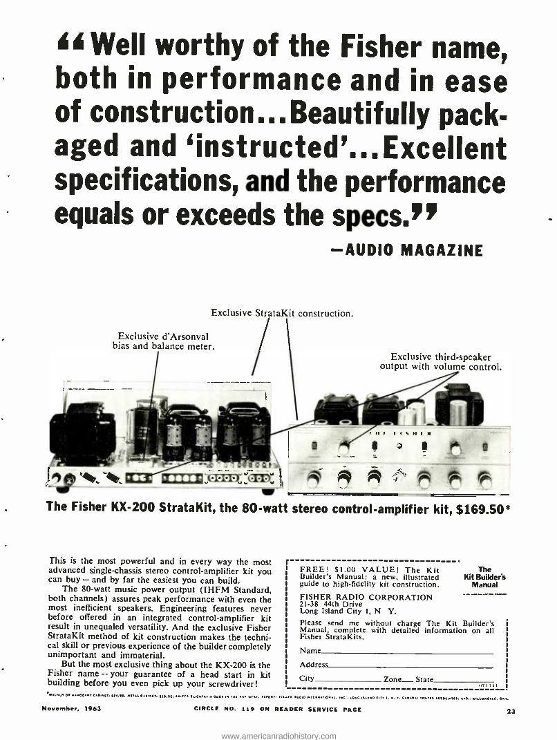
AA Well worthy of the Fisher name, both in performance and in ease of construction... Beautifully pack- aged and `instructed'... Excellent specifications, and the performance equals or exceeds the specs!'
-AUDIO MAGAZINE
Exclusive StrataKit con tru,:tion.
Exclusive d'Arsonval bias and balance meter.
Exclusive third- speaker output with volume control.
= r r
w The Fisher KX -200 StrataKit, the 80 -watt stereo control -amplifier kit, $169.50*
This is the most powerful and in every way the most advanced single- chassis stereo control- amplifier kit you can buy - and by far the easiest you can build.
The 80 -watt music power output (IHFM Standard, both channels) assures peak performance with even the most inefficient speakers. Engineering features never before offered in an integrated control -amplifier kit result in unequaled versatility. And the exclusive Fisher StrataKit method of kit construction makes the techni- cal skill or previous experience of the builder completely unimportant and immaterial.
But the most exclusive thing about the KX -200 is the Fisher name -- your guarantee of a head start in kit building before you even pick up your screwdriver!
r FREE! $1.00 VALUE! The Kit Builder's Manual: a new, illustrated guide to high -fidelity kit construction.
FISHER RADIO CORPORATION 21 -38 44th Drive Long Island City I, N Y. Please send me without charge The Kit Builder's Manual, complete with detailed information on all Fisher StrataKits.
The Kit Builder's
Manual
Name
Address
City Zone- State l I l l
MEINUT o..u,00ANY C..ICT. SN.ss. NCYAL t.INCT. $15.95. Y.ICtS SLIGHTLY MON.. IN THE I.. WCST. ts.O.T. ,SHE. sAOIO INTE.NLT.O.L. ,NC.. LONG , CITY t, N. Y. I TI.YCL SSOC,ATC,. LTD.. NILIOWGLC. CMI.
November, 1963 CIRCLE NO. 119 ON READER SERVICE PAGE 23
www.americanradiohistory.com
FOR
ADULTS
ONLY!
with a 20 -kc. square wave reproduced better than most top -quality amplifiers will do at 10 kc. There was no ringing or overshoot, except that with capaci- tive loads greater than 0.1 µf. shunting an 8 -ohm resistor, there was a single cycle of overshoot. Hum and noise were 79 db below 10 watts, or 85 db below rated output.
One of the striking properties of this amplifier is its cool operation. In normal service, it does not get even faintly warm, which is quite a contrast to vat -
uum -tube amplifiers of comparable power output. In listening tests, it had an impressive clarity and solidity which place it in the top rank of amplifiers. We were unable to drive it to overload with any speakers at our disposal (our ears and /or speakers gave up first) . At the highest levels as well as the lowest it produced an effortless and transparent sound which was limited only by the as- sociated speakers and program material.
The "Acoustech I" power amplifier sells for $395.00 with metal cage.
Audio Dynamcs ADC -14 Speaker System For copy of Manufacturer's brochure, circle No. 5S on coupon (page 17).
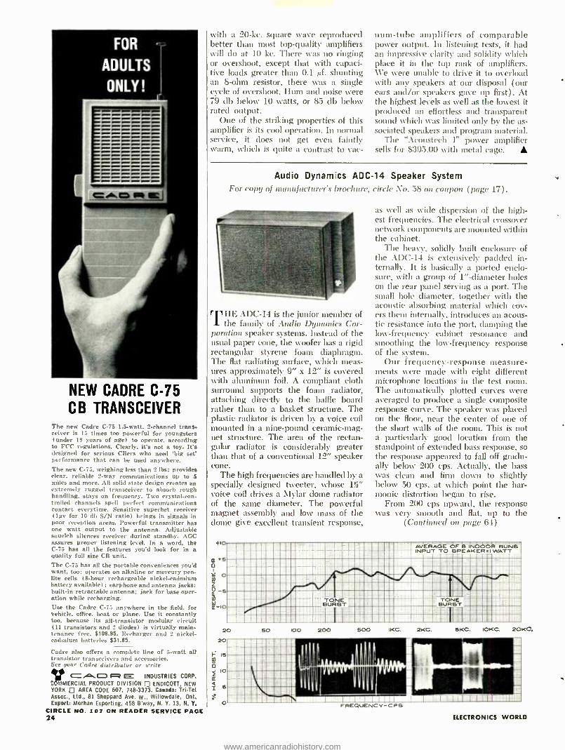
NEW CADRE C -75 CB TRANSCEIVER
The new Cadre C -75 1.5 -watt, 2- channel trans- ceiver is 15 times too powerful for youngsters (under 18 years of age) to operate, according
to FCC regulations. Clearly, it's not a toy. It's designed for serious CBers who need 'big set' performance that can be used anywhere. The new C -75, weighing less than 2 lbs: provides clear, reliable 2 -way communications up to 5 miles and more. All solid state design creates an extremely rugged transceiver to absorb rough handling, stays on frequency. Two crystal -con- trolled channels spell perfect communications contact everytime. Sensitive superhet receiver (1µv for 10 db S/N ratio) brings in signals in poor reception areas. Powerful transmitter has one watt output to the antenna. Adjustable squelch silences receiver during standby. AGC assures proper listening level. In a word, the C -75 has all the features you'd look for in a quality full size CB unit. The C -75 has all the portable conveniences you'd want, too: operates on alkaline or mercury pen - lite cells (S -hour rechargeable nickel- cadmium battery available) : earphone and antenna jacks; built -in retractable antenna; jack for base oper- ation while recharging. Use the Cadre C -75 anywhere in the field. for vehicle, office, boat or plane. Use it constantly too, because its all- transistor modular circuit (11 transistors and 2 diodes) is virtually main- tenance free. $109.95. Recharger and 2 nickel - cadmium batterie, $31.85.
Cadre also offers a complete line of 5 -watt all transistor transceivers and accessories. Sue your Cadre distributor or write
CAIN R E INDUSTRIES CORP. C MERCIAL PRODUCT DIVISION ENDICOTT, NEW YORK AREA CODE 607, 748.3373. Canada: Tri -Tel Assoc., Ltd., 81 Sheppard Ave. w., Willowdale, Ont. Export: Morhan Exporting, 458 B'way, N. Y. 13, N. Y.
CIRCLE NO. 107 ON READER SERVICE PAGE 24
THE ADC -14 is the junior member of the family of Audio Dynamics Cor-
poration speaker systems. Instead of the usual paper cone, the woofer has a rigid rectangular styrene foam diaphragm. The flat radiating surface, which meas- ures approximately 9" x 12" is covered with aluminum foil. A compliant cloth surround supports the foam radiator, attaching directly to the baffle board rather than to a basket structure. The plastic radiator is driven by a voice coil mounted in a nine -pound ceramic -mag- net structure. The area of the rectan- gular radiator is considerably greater than that of a conventional 12" speaker cone.
The high frequencies are handled by a specially designed tweeter, whose 1"i" voice coil drives a Mylar dome radiator of the same diameter. The powerful magnet assembly and low mass of the dome give excellent transient response,
4.10
m 5 0 W o a
-5 (0
Q-Io
as well as wide dispersion of the high- est frequencies. The electrical crossover network components are mounted within the cabinet.
The heavy, solidly built enclosure of the ADC -14 is extensively padded in- ternally. It is basically a ported enclo- sure, with a group of 1 "- diameter holes on the rear panel serving as a port. The small hole diameter, together with the acoustic absorbing material which cov- ers them internally, introduces an acous- tic resistance into the port, damping the low- frequency cabinet resonance and smoothing the low- frequency response of the system.
Our frequency- response measure- ments were made with eight different microphone locations in the test room. The automatically plotted curves were averaged to produce a single composite response curve. The speaker was placed on the floor, near the center of one of the short walls of the room. This is not a particularly good location from the standpoint of extended bass response, so the response appeared to fall off gradu- ally below 200 cps. Actually, the bass was clean and firm down to slightly below 50 cps, at which point the har- monic distortion began to rise.
From 200 cps upward, the response was very smooth and flat, up to the
(Continued on page 64)
AVERAGE OF INDOOR RUNS INPUT TO SPEAKER =1 WATT
20 20
F 15 dl o
lo Q 4
o FREQUENCY -CPS ELECTRONICS WORLD
www.americanradiohistory.com
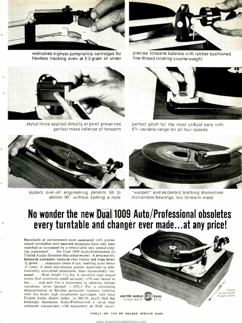
welcomes highest compliance cartridges for flawless tracking even at 1 2 gram or under
stylus force applied directly at pivot preserves
precise tonearm balance with rubber cushioned fine -thread rotating counterweight
perfect pitch for the most critical ears with perfect mass balance of tonearm 6 °i° variable range for all four speeds
superb over -all engineering permits tilt to "warped.' and eccentric tracking dramatizes almost 90 without spilling a note frictionless bearings. low tonearm mass
No wonder the new Dual 1009 Auto /Professional obsoletes every turntable and changer ever made...at any price!
Standards of performance once associated with proces- sional turntables and separate tonearms have now been matched or surpassed by a remarkable new record play- ing instrument ... the Dual 1009 Auto /Professional by United Audio. Consider this achievement: A dynamically balanced automatic tonearm that tracks and trips below 1/2 gram ... resonance below 8 cps, tracking error below .5° /inch. A solid non -ferrous platter machined to elec- tronically controlled tolerances, then dynamically bal- anced ... final weight 71/2 lbs. A powerful high- torque motor that maintains speed accuracy with one record or ten ... and acts like a hysteresis in resisting voltage variations (even beyond ±- 10%.) For a convincing demonstration of flawless automatic tonearm tracking with the finest high compliance cartridges, visit your United Audio dealer today. At $94.75, you'll find the strikingly handsome Auto /Professional a value that welcomes comparison with equipment at $100 more.'
UNITED AUDIO l.!l DUAL 12 West 18th St. N.Y.11
` famous ' elevator- action
changer spindlo
CIRCLE NO. 159 ON READER SERVICE PAGE
www.americanradiohistory.com
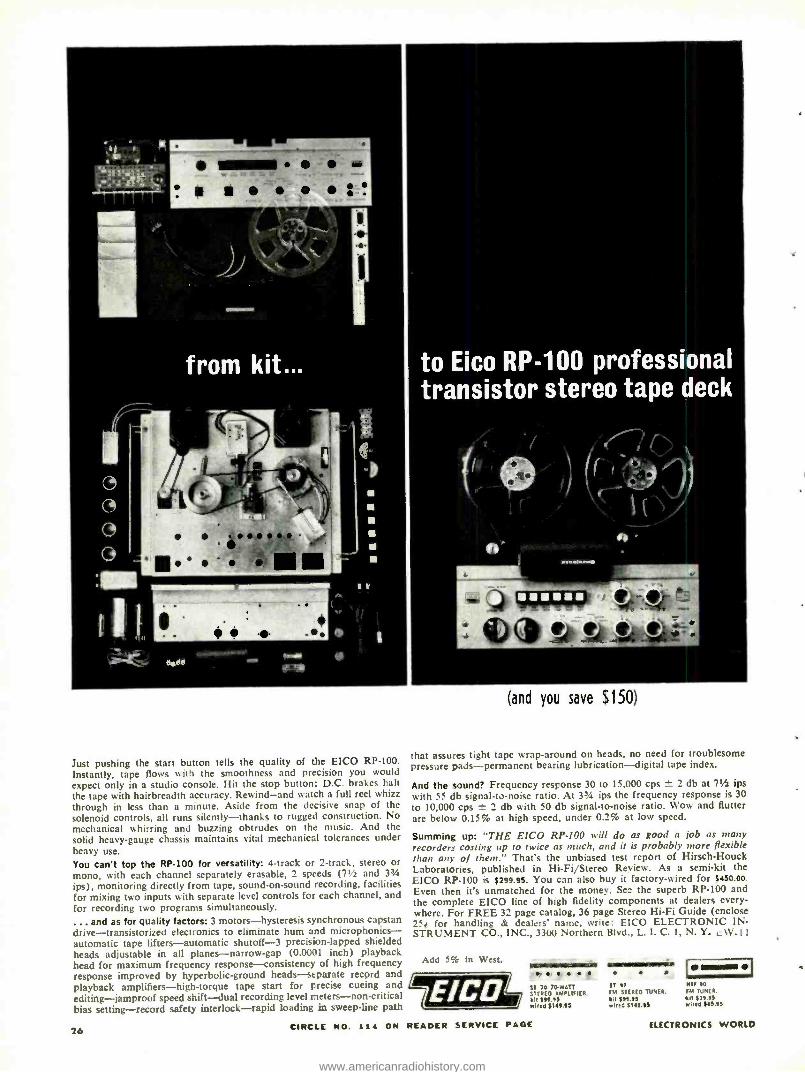
to Eico RP -100 professional transistor stereo tape deck
Just pushing the start button tells the quality of the EICO RP -100. Instantly, tape flows with the smoothness and precision you would expect only in a studio console. Hit the stop button: D.C. brakes halt the tape with hairbreadth accuracy. Rewind -and wat:h a full reel whizz through in less than a minute. Aside from the decisive snap of the solenoid controls, all runs silently- thanks to rugged construction. No mechanical whirring and buzzing obtrudes on the music. And the solid heavy -gauge chassis maintains vital mechanical tolerances under heavy use. You can't top the RP -100 for versatility: 4 -track or 2- track, stereo or mono, with each channel separately erasable, 2 speeds (71/2 and 344
ips), monitoring directly from tape, sound -on -sound recording, facilities for mixing two inputs with separate level controls for each channel, and for recording two programs simultaneously. .. and as for quality factors: 3 motors -hysteresis synchronous capstan
drive -transistorized electronics to eliminate hum and microphonics- automatic tape lifters- automatic shutoff -3 precision- lapped shielded heads adjustable in all planes- narrow -gap (0.0001 inch) playback bead for maximum frequency response-consistency of high frequency response improved by hyperbolic -ground heads -separate record and playback amplifiers- high- torque tape start for precise cueing and L.., editing -jamproof speed shift -dual recording level meters -non -critical bias setting- record safety interlock -rapid loading in sweep -line path
CIRCLE NO. 1t4 ON READER SERVICE PAGE
(and you save S150)
that assu-es tight tape wrap- around on heads, no need for troublesome pressure pads- permanent bearing lubrication -digital tape index.
And the sound? Frequency response 30 to 15,000 cps 2 db at 71/2 ips with 55 db signal -to -noise ratio. At 33/4 ips the frequency response is 30 to 10,000 cps ± 2 db with 50 db signal -to -noise ratio. Wow and flutter are below 0.15% at high speed, under 0.2% at low speed.
Summing up: THE EICO RP -100 will do as good a job as many recorders costing up to twice as much, and it is probably more flexible than any of them." That's the unbiased test report of Hirsch -Houck Laboratories, published in Hi -Fi /Stereo Review. As a semi -kit the EICO RP -100 is $295.95. You can also buy it factory -wired for $450.00.
Even then it's unmatched for the money. See the superb RP -100 and the complete EICO line of high fidelity components at dealers every- where. For FREE 32 page catalog, 36 page Stereo Hi -Fi Guide (enclose 25i for handling & dealeTs' name, write: EICO ELECTRONIC IN- STRUMENT CO., INC., 3300 Northern Blvd., L. I. C. 1, N. Y. cW -11
Add 5% in West.
26
ST 70 70.WATT STEREO AMPLIFIER. 10 RIO II wind $141115
e
ST 07 TM STEREO TUNER. 10 55115 wired 5740.05
NTT 00 TM TUNEN. mit 570.05 wired $55.55
ELECTRONICS WORLD
www.americanradiohistory.com
JET
TRANSPORT
COMMUNICATIONS By R. L. CON HAI M
Reliable radio communications are vital to the safe operation of modern high -s
jet aircraft. They keep the pilot in
constant touch with the ground controller' and make air travel safe as well as rapid.
YOU'RE comfortably seated in a plush seat of a TWA Boeing 707, looking out the window at the cloud cover far below you. Only a few minutes before, you had left Chicago's O'Hare Field for the 57 minute flight to Dayton, Ohio.
Now the flight is nearly over and you're wondering just how the pilot will manage to penetrate the cloud cover and find the Dayton Municipal Airport.
Unknown to you, the aircraft crew has been in constant radio communication with the Indianapolis Traffic Control Center, operated by the Federal Aviation Agency. Now, as the plane approaches Dayton, the earphones crackle. It's the Indianapolis Controller.
"TWA 24, you're cleared to the Dayton VOR. Descend and maintain five thou- sand."
The first officer picks up his microphone, pushes the press -to -talk button. "TWA 24, Roger. The Dayton VOR descend and maintain five thousand."
Again the headphones come to life. "TWA 24, Roger. Expect ILS approach to runway six to Dayton Municipal. Contact Dayton Approach Control on one one eight point zero. Good day, sir."
The co -pilot acknowledges his instructions. His hand reaches for the v.h.f. con- trol head. He turns the whole- megacycle knob until the digital control reaches 118. Now he turns the one -tenth megacycle knob until the digital indicator reads zero. He picks up his mike, "Dayton Approach Control, TWA 24." There is an immediate acknowledgement.
"TWA 24, radar contact seven miles northwest of Dayton VOR. Depart the VOR heading one eight zero. Maintain five thousand for radar vector to ILS runway six approach. Time, four eight and one -quarter. Altimeter three zero one six."
The first officer repeats the information so there can be no misunderstanding. The Dayton Approach Control voice continues: "Dayton weather estimated nine thou- sand, overcast. Visibility, six miles, haze, winds northeast at seven knots.
The controller then gives instructions to vector the flight to the ILS System. Once over the outer marker, the pilot is advised to contact Dayton Tower on 119.5 mc.
While you have been riding in luxurious comfort, one of the most complex and efficient communication networks ever devised has been in constant operation, pro- viding the pilot of your plane with specific instructions and keeping him up- to -the- minute on every factor of flight about which he must be aware. Two giant networks of ground -to -air communications, one operated by the FAA, the other by ARINC (Aeronautical Radio, Incorporated), provide complete radio coverage for today's
November, 1063 27
www.americanradiohistory.com
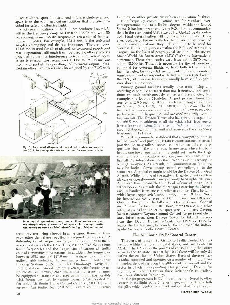
thriving air transport industry. And this is entirely over and apart from the radio navigation facilities that are also pro- vided for safe and effective flight.
Most communications in the U.S. are conducted on v.h.f., within the frequency range of 118.0 to 135.95 mc. with 50 kc. spacing. Some specific frequencies are assigned for par- ticular purposes. For example, 121.5 mc. is the universal simplex emergency and distress frequency. The frequency 121.6 mc. is used for air -to -air and air -to- ground search and rescue operations, although it can be used for other purposes provided no harmful interference to search and rescue oper- ations is caused. The frequencies 121.65 to 121.95 mc. are used for airport utility operation, and to control airport lights. Certain other frequencies are also assigned by the FCC with
Fig. 1. Functional diagram of typical h.f system as used in
the DC -8. Two complete systems are used for maximum safety.
In a typical operations room, one to three controllers pass
the aircraft along a sector of air space. An average center can handle as many as 2000 aircraft during a 24 -hour period.
secondary use being allowed in some cases. Basically, how- ever, other than these specifically assigned frequencies, the determination of frequencies for ground operations is made in cooperation with the FAA. Thus, it is the FAA that assigns tower frequencies and the frequencies of various air traffic control communications stations. In addition, the frequencies between 108.1 mc. and 117.9 mc. are assigned to v.h.f. navi- gational aids including the localizer portion of Instrument Landing Systems (ILS) and v.h.f. Omnirange Navigation ( VOR ) stations. Aircraft are not given specific frequency as- signments. As a consequence, the modern jet transport must be equipped to transmit and receive on any of the possible v.h.f. frequencies used by various towers, FAA -operated ra- dar units, Air Route Traffic Control Centers (ARTCC), and Aeronautical Radio, Inc. (ARINC) private communication
28
facilities, or other private aircraft communication facilities. High- frequency communications are for standard over-
seas operations and, to a limited degree, within the United States. It has been proposed by the FCC that h.f. communica- tions in the continental U.S. (excluding Alaska) be discontin- ued. Final determination will be made prior to 1965. How- ever, because of the necessity for the longer ranges provided by h.f. communications, they will continue to be used for overseas flights. Frequencies within the h.f. band are usually assigned on the basis of geographical location on the several Major World Air Route Areas (AIWARA's) by international agreement. These frequencies vary from about 2875 kc. to about 18,000 kc. Thus, it is necessary for the jet transport, equipped for overseas flights, to have both h.f. and v.h.f. facilities. Also, because v.h.f. assignments in foreign countries sometimes do not correspond with the frequencies used within the U.S., jet overseas transports usually have v.h.f. capabil- ities above 135.95 mc.
Primary ground facilities usually have transmitting and receiving capability on more than one frequency, and some- times transmit simultaneously on several frequencies. For example, the Dayton Municipal Airport primary tower fre- quency is 119.5 mc., but it also has transmitting capabilities on 278 kc., 121.5, 121.9, 126.2, 243.0, and 257.8 mc. The lat- ter two frequencies are considered in aircraft communication parlance as u.h.f. frequencies and are used primarily by mili- tary aircraft. The Dayton Tower also has receiving capability on 122.5 mc. in addition to all the v.h.f.- u.h.f. frequencies it uses for transmitting. Of course, all FAA and military oper- ated facilities can both transmit and receive on the emergency frequency of 121.5 mc.
While it is commonly considered that a transport pilot talks to "the tower" and possibly certain enroute stations, in actual practice, he may talk to several controllers on different fre- quencies, but in the sane area. In any area where traffic is
heavy, one tower operator simply could not handle the large volume of communications necessary, nor have at his finger- tips all the information necessary to transmit to arriving or leaving transports. As a result, the communication functions may be broken down among several controllers, all in the same area. A typical example would be the Dayton Municipal Airport. While not one of the nation's largest -it ranks 40th in air carrier operations -its close proximity to Wright- Patterson Air Force Base means that the local volume of air traffic is
rather heavy. As a result, the jet transport entering the Dayton area, is handed from one controller to another. First, he talks with Dayton Approach Control, probably on 118.0 mc. Next, his instructions come from the Dayton Tower on 119.5 mc. Once on the ground, he talks with Dayton Ground Control on 121.9 mc. for taxiing instructions, ramps to use, and other information. When the jet transport is ready to leave Dayton, he first contacts Dayton Ground Control for pertinent clear- ance information, then Dayton Tower for take -off instruc- tions, then Dayton Departure Control on 119.9 mc. Once he leaves the Dayton area, he is under the control of the Indian- apolis Air Route Traffic Control Center.
The Air Route Traffic Control Centers
There are, at present, 28 Air Route Traffic Control Centers located within the 48 continental states, and two located in Alaska. The FAA is in the process of consolidating the center areas in the 48 states so that by 1965 there will be only 21 within the continental United States. Each of these centers is radar equipped and operates on a number of different fre- quencies, depending upon the altitude of the aircraft and the sector in which it is operating. Our jet leaving Dayton, for example, will contact two or three Indianapolis controllers, each on a different frequency.
As the jet progresses in flight, it will be transferred to other centers in its flight path. In every case, each controller tells the pilot which center to contact and on what frequency, so
ELECTRONICS WORLD
www.americanradiohistory.com
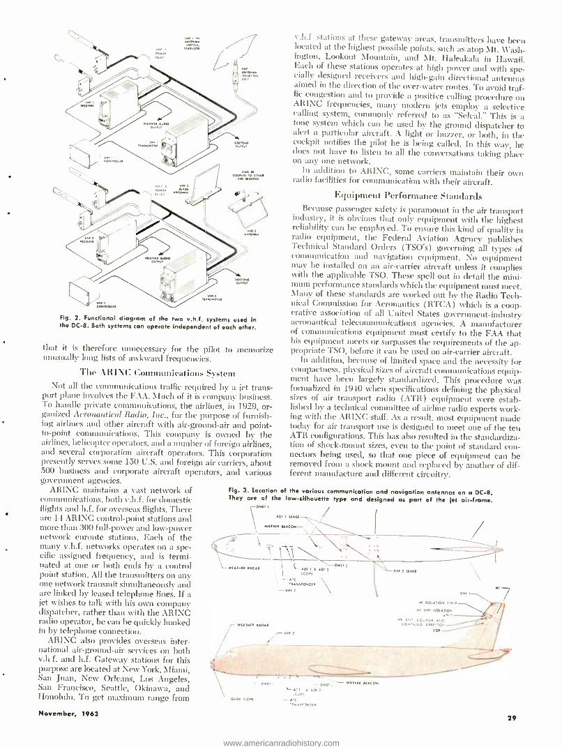
44,
Fig. 2. Functional diagram of the two v.h.f. systems used in the DC -8. Both systems can operate independent of each other.
that it is therefore unnecessary for the pilot to memorize unusually long lists of awkward frequencies.
The ARINC Communications System Not all the communications traffic required by a jet trans-
port plane involves the FAA. Much of it is company business. To handle private communications, the airlines, in 1929, or- ganized Aeronautical Radio, Inc., for the purpose of furnish- ing airlines and other aircraft with air- ground -air and point - to- point communications. This company is owned by the airlines, helicopter operators, and a number of foreign airlines, and several corporation aircraft operators. This corporation presently serves some 150 U.S. and foreign air carriers, about 500 business and corporate aircraft operators, and various government agencies.
ARINC maintains a vast network of communications, both v.h.f. for domestic flights and h.f. for overseas flights. There are 14 ARINC control -point stations and more than 300 full -power and low -power network enroute stations. Each of the many v.h.f. networks operates on a spe- cific assigned frequency, and is termi- nated at one or both ends by a control point station. All the transmitters on any one network transmit simultaneously and are linked by leased telephone lines. If a jet wishes to talk with his own company dispatcher, rather than with the ARINC radio operator, he can be quickly hooked in by telephone connection.
ARINC also provides overseas inter- national air- ground -air services on both v.h f. and h.f. Gateway stations for this c! purpose are located at New York, Miami, San Juan, New Orleans, Los Angeles, San Francisco, Seattle, Okinawa, and Honolulu. To get maximum range from
v.h.f stations at these gateway areas, transmitters have been located at the highest possible points, such as atop \It. \\'ash - ington, Lookout Mountain, and \1t. Haleakala in Hawaii. Each of these stations operates at high power and with spe- cially designed receivers and high -gain directional antennas aimed in the direction of the over -water routes. To avoid traf- fic congestion and to provide a positive calling procedure on ARINC frequencies, many modern jets employ a selective calling system, commonly referred to as "Selcal." This is a tone system which can be used by the ground dispatcher to alert a particular aircraft. A light or buzzer, or both, in the cockpit notifies the pilot he is being called. Ln this way, he sloes not have to listen to all the conversations taking place on any one network.
In addition to ARINC, some carriers maintain their own radio facilities for communication with their aircraft.
Equipment Performance Standards Because passenger safety is paramount in the air transport
industry, it is obvious that only equipment with the highest reliability can be employed. To ensure this kind of quality in radio equipment, the Federal Aviation Agency publishes Technical Standard Orders (TSO's) governing all types of communication and navigation equipment. No equipment may be installed on an air -carrier aircraft unless it complies with the applicable TSO. These spell out in detail the mini- mum performance standards which the equipment must meet. Man), of these standards are worked out by the Radio Tech- nical Commission for Aeronautics (RTCA ) which is a coop- erative association of all United States government -industry aeronautical telecommunications agencies. A manufacturer of communications equipment must certify to the FAA that his equipment meets or surpasses the requirements of the ap- propriate TSO, before it can be used on air -carrier aircraft.
In addition, because of limited space and the necessity for compactness, physical sizes of aircraft communications equip- ment have been largely standardized. This procedure was formalized in 1940 when specifications defining the physical sizes of air transport radio (ATR) equipment were estab- lished by a technical committee of airline radio experts work- ing xvith the ARINC staff. As a result, most equipment made today for air transport use is designed to meet one of the ten ATR configurations. This has also resulted in the standardiza- tion of shock -mount sizes, even to the point of standard con- nectors being used, so that one piece of equipment can be removed from a shock mount and replaced by another of dif- ferent manufacture and different circuitry.
Fig. 3. Location of the various communication and navigation antennas on a DC -8. They are of the low- silhouette type and designed as part of the ¡et air- frame.
\WM,
I
DEI SINSf -H_.
MAI,,, BEACON - I ,/ `
OMIT : WIIwf unu D. I { DE 7 i DI ] SIMSf ;OOPS `u
,.NS.ONDf.
WE.Nn .Dr
November, 1963
-GODS SLOPS
N1 ISOLATION S'. i. w1 YMt ISOI,IO4
MI a (O..IH
Mf
VIII 7
OOH, 4..1'IOE- v0.
.. PHI; i --OMI,: -'.1 O17 IG0.5
. ,C r.NS'JNDE
- M.... !ICON
29
www.americanradiohistory.com

Practically all jet communications equipment is remotely controlled. The controls usually include frequency -changing devices, volume, squelch, and function controls. There is
some standardization of control panel sizes, but controls may also be custom designed to fit the requirements of particular aircraft or the desires of different airlines. This does not pre- sent any unusual problems.
With such great variety of radios, it is obvious that a com- plete audio system for each would take up too much space and cause too much confusion in operation. Consequently, most aircraft receivers are provided with 500- to 600 -ohm output which is fed into an audio panel, so that practically any combination of equipment can be fed into any combination of speaker or headset outputs. In addition, the audio panel is used for controlling intercom, passenger public address
Fig. 4. This v.h.f. aircraft transceiver, made by Collins, uses semiconductors and miniature vacuum tubes to reduce size.
Fig. 5. This modern h.f. transceiver uses 14 tubes and 100 tran- sitors and has 28,000 discrete channels between 2 and 30 mc.
functions, and music reproducer systems. Each United Air Lines jet transport, including DC -8's, B- 720's, and Caravelles, is equipped with a 40 -watt Collins audio amplifier and Gables tape reproducer. Speakers are located throughout the cabin with a speaker in each lavatory and the cockpit. Either the pilot, co -pilot or a stewardess can use the aircraft audio sys- tem to make pertinent announcements.
Power for all communications equipment and for other electrical and electronic equipment on board is provided from 28 -volt d.c. battery sources and 115- v.a.c., 400 -cycle sources. Most of the primary power for communications equipment is derived from 115- v.a.c., 400 -cycle generators. In the DC -8, for example, each of the four jet engines operates an a.c. generator. There is ample generator capacity. All of the systems on a DC -8 requiring 400 -cycle a.c. can be sup- plied from the output of 1;i generators. Thus, there are always two in reserve for contingencies.
The location of remotely controlled communications and other electronic gear is determined in the design of each indi- vidual jet transport. In the DC -8, the equipment is located in
radio racks behind the captain's position; in the Boeing 720, the equipment is beneath the floor aft of the cockpit; while in
30
the Caravelle, radio equipment racks are aft of the cockpit on the second officer's side of the aircraft.
Fig. 1 shows a functional diagram of a typical high -fre- quency system as employed in the Douglas DC -8. Although only a single system is shown, two complete systems are nor- mally used to provide maximum safety should a failure occur in one of the systems. This system operates in the 2- to 22 -mc. range utilizing up to 168 common transmit -receive chan- nels, 24 receive -only channels, and up to 23 transmit -only channels. Transmitter and receiver frequency selection is
controlled from a panel in the cockpit, and all tuning and antenna loading are entirely automatic, performed by an in- genious servo system. In the receivers, i.f. crystal bandpass filters are employed, resulting in a bandwidth of only 3 kc. giving the receiver excellent selectivity. Isolation between the two hi systems, and between transmitters and receivers, is provided by switching systems in the lightning- arrester unit. With this system, it is possible to receive with both h.f. receivers simultaneously, although only one transmitter can be used at a time.
Fig. 2 shows, in functional form, the interconnection of the v.h.f. communications systems on the standard DC -8. Both v.h.f. systems operate independently of each other, so that both transmitters can be operated simultaneously if desired. The control panel is located in the pilot's overhead switch panel and includes two frequency selectors with concentric volume control, two on -off switches, two squelch controls, and two single -channel /double -channel switches. In the double - channel position, the transmitter carrier position is 6 mc. above the receiver frequency. This action is functional only when the frequency indicator reads 118.0 through 120.95 or 127.0 through 129.95 mc.
Fig. 3 shows the location of the various communications and navigation antennas on a DC -8. Antenna locations and sizes on jet aircraft differ from the conventional piston -engine aircraft. The greater speed of jet aircraft demands antennas with low silhouette and, consequently, lower drag.
Because of the large numbers of equipment available, and because each airline has its own preferences based upon ex- perience, the selection of communications equipment is done by airline executives in cooperation with the airframe manu- facturers. The Douglas systems shown in Figs. 1 and 2 are standard systems offered by Douglas. On the other hand. United Air Lines' DC -8's, B- 720's, and Caravelles employ Collins equipment specified by the airlines. Each United plane has two Collins 51X -2 receivers and 17L -7 transmitters. The receivers are used for both v.h.f. navigation and commu- nications. On the nine DC -8's flying between the mainland and Honolulu, dual h.f. transmitters and receivers made by Aero Communications Company, and known as the "Atom" and the "Star" are installed. These over -water planes also carry PRC -17 military type walkie- talkies and Granger self - contained life raft beacon transmitters operating on the 121.5 -mc. emergency frequency. Other airlines may specify different equipment, but it is common practice to employ the antennas provided by the airframe manufacturer since these are an integral part of the aircraft, designed and located for best aerodynamic characteristics as well as optimum com- munications efficiency and radiation patterns.
Typical Equipment The Collins airborne v.h.f. transmitter, Model 17L -7, is the
latest in a series which has become quite popular among air- lines. It provides 25 -watt output in the 118.0- to 151.95 -mc. range with 680 crystal -controlled channels 50 kc. apart. The greater coverage is provided to accommodate communica- tions in certain overseas areas where v.h.f. higher than 135.95 mc. may be used. The transmitter is partially transistorized, weighs 14 pounds, and is housed in a short % ATR case. The entire 680- channel coverage is accomplished using only 38 crystals by frequency- synthesis (Continued on page 94)
ELECTRONICS WORLD
www.americanradiohistory.com
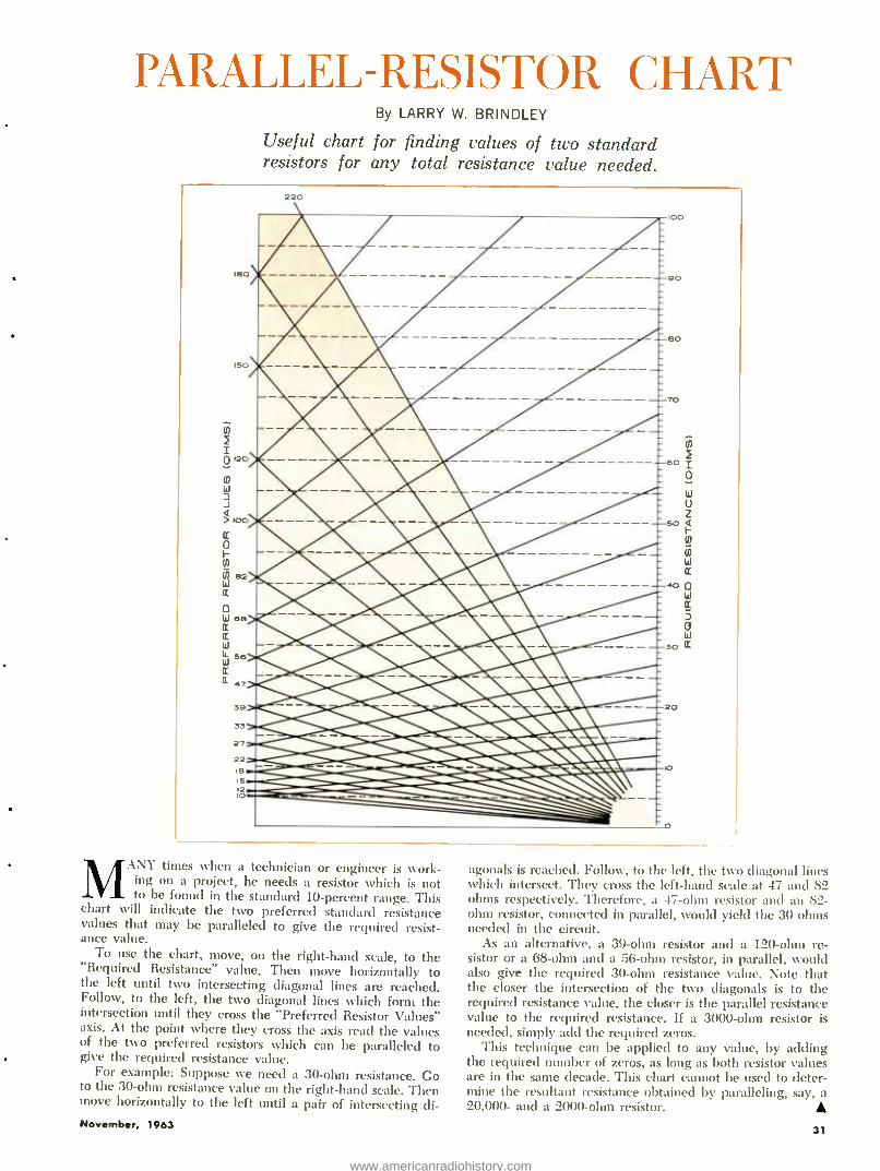
PARALLEL -RESISTOR (;HART By LARRY W. BRINDLEY
Useful chart for finding values of two standard resistors for any total resistance value needed.
220
N
I o '20
N W J J 4 > ioo
o
N
(7 82 W Q
o W 68 Q Q w IL W Q Ci 47
N
60 I o
W
o z
50 4
N Ul W Er
40 0 W Q
] o W
30 a
MANY times when a technician or engineer is work- ing on a project, he needs a resistor which is not to be found in the standard 10- percent range. This
chart \vi11 indicate the two preferred standard resistance values that may be paralleled to give the required resist- ance value.
To use the chart, move, on the right -hand scale, to the "Required Resistance" value. Then move horizontally to the left until two intersecting diagonal lines are reached. Follow, to the left, the two diagonal lines which form the intersection until they cross the "Preferred Resistor Values" axis. At the point where they cross the axis read the values of the two preferred resistors which can be paralleled to give the required resistance value.
For example: Suppose we need a 30 -ohm resistance. Co to the 30 -ohm resistance value on the right -hand scale. Then move horizontally to the left until a pair of intersecting di- November, 1963
agonals is reached. Follow, to the left, the two diagonal lines which intersect. They cross the left -hand scale at 47 and 82 ohms respectively. Therefore, a 4 i -ohm resistor and an 82- ohm resistor, connected in parallel, would yield the 30 ohms needed in the circuit.
As an alternative, a 39 -ohm resistor and a 120 -olun re- sistor or a 68 -ohm and a 56 -ohm resistor, in parallel, would also give the required 30 -ohm resistance value. Note that the closer the intersection of the two diagonals is to the required resistance value, the closer is the parallel resistance value to the required resistance. If a 3000 -ohm resistor is needed, simply add the required zeros.
This technique can be applied to any value, by adding the required number of zeros, as long as both resistor values are in the same decade. This chart cannot be used to deter- mine the resultant resistance obtained by paralleling, say, a 20,000- and a 2000 -ohm resistor.
31
www.americanradiohistory.com
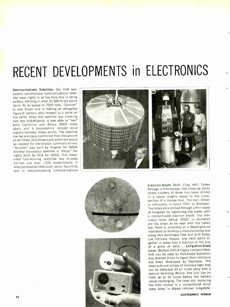
RECENT DEVELOPMENTS in ELECTRONICS
Communications Satellites. Our first suc-
cessful synchronous communications satel-
lite (near right) is, at the time this is being
written, whirling in orbit 22,300 miles above
earth. At its speed of 7000 mph, "Syncom" is over Brazil and is making an elongated figure -8 pattern with respect to a point on
the earth. When the satellite was hovering
over the mid -Atlantic, it was able to "see" both California and Africa, 8000 miles apart, and it successfully relayed voice
signals between these points. The satellite can be precisely controlled from the ground at all times. Only three such satellites would
be needed for world -wide communications. "Syncom" was built by Hughes for NASA.
Another successful satellite is "Relay" (far right), built by RCA for NASA. This lower -
orbit fast -moving satellite has already carried out over 1350 experiments in
intercontinental television, voice, facsimile, and in data -processing communications.
32
Electron -Beam Drill. (Top left) Taken
through a microscope, this close -up photo
shows clusters of three tiny holes drilled in a space roughly equal to the cross -
section of a human hair. The hair, shown
in silhouette, is about .004" in diameter. The holes were drilled through a thin sheet
of tungsten by vaporizing the metal with a concentrated electron beam. The indi-
vidual holes (about .0008" in diameter) are too small to be seen with the naked
eye. Work is underway at a Westinghouse laboratory to develop a manufacturing tool
using this technique that will drill holes,
cut intricate shapes, and weld parts to-
gether in areas only a fraction of the size
of a grain of sand.... Lilliputian -Sized
Laser. (Bottom left) A highly compact laser
that can be used by distressed boatsmen
and downed pilots to signal their positions has been developed by Raytheon. The
laser puts out pulses of invisible light that can be detected 30 air miles away with a
special receiving device. The unit can be
fired up to 50 times before the battery needs recharging. The laser rod, replacing
the ruby crystal in a conventional solid -
state laser, is doped calcium tungstate.
ELECTRONICS WORLD
www.americanradiohistory.com
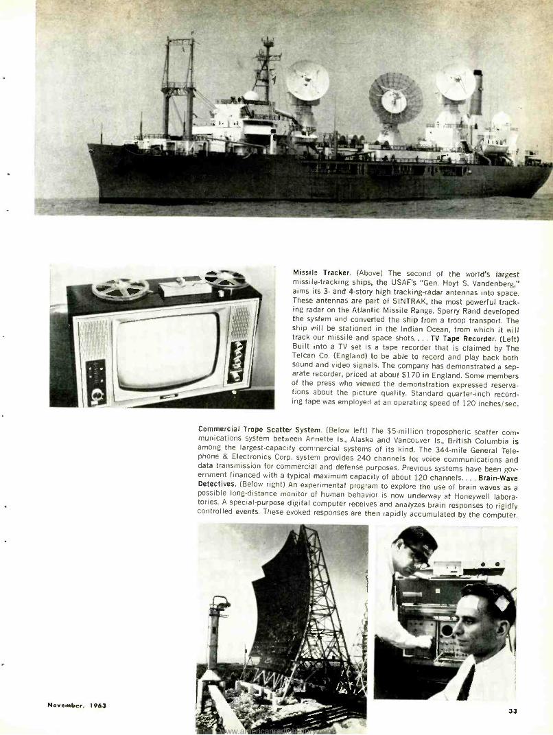
November, 1963
Missile Tracker. (Above) The second of the world's largest missile- tracking ships, the USAF's "Gen. Hoyt S. Vandenberg," aims its 3- and 4 -story high tracking -radar antennas into space. These antennas are part of SINTRAK, the most powerful track- ing radar on the Atlantic Missile Range. Sperry Rand developed the system and converted the ship from a troop transport. The ship v'ill be stationed in the Indian Ocean, from which it will track our missile and space shots.... TV Tape Recorder. (Left) Built into a TV set is a tape recorder that is claimed by The Telcan Co. (England) to be able to record and play back both sound and video signals. The company has demonstrated a sep- arate recorder, priced at about $170 in England. Some members of the press who viewed the demonstration expressed reserva- tions about the picture quality. Standard quarter -inch record- ing tape was employed at an operat;ng speed of 120 inches /sec.
Commercial Tropo Scatter System. (Below left) The $5- mil'ion tropospheric scatter com- munications system between Arnette Is., Alaska and Vancouver Is., British Columbia is among the largest -capacity commercial systems of its kind. The 344 -mile General Tele- phone & Electronics Corp. system provides 240 channels for voice communications and data transmission for commercial and defense purposes. Previous systems have been gov- ernment financed with a typical maximum capacity of about 120 channels.... Brain -Wave Detectives. (Below right) An experimental program to explore the use of brain waves as a possible long- distance monitor of human behavior is now underway at Honeywell labora- tories. A special -purpose digital computer receives and analyzes brain responses to rigidly controlled events. These evoked responses are then rapidly accumulated by the computer.
33
www.americanradiohistory.com
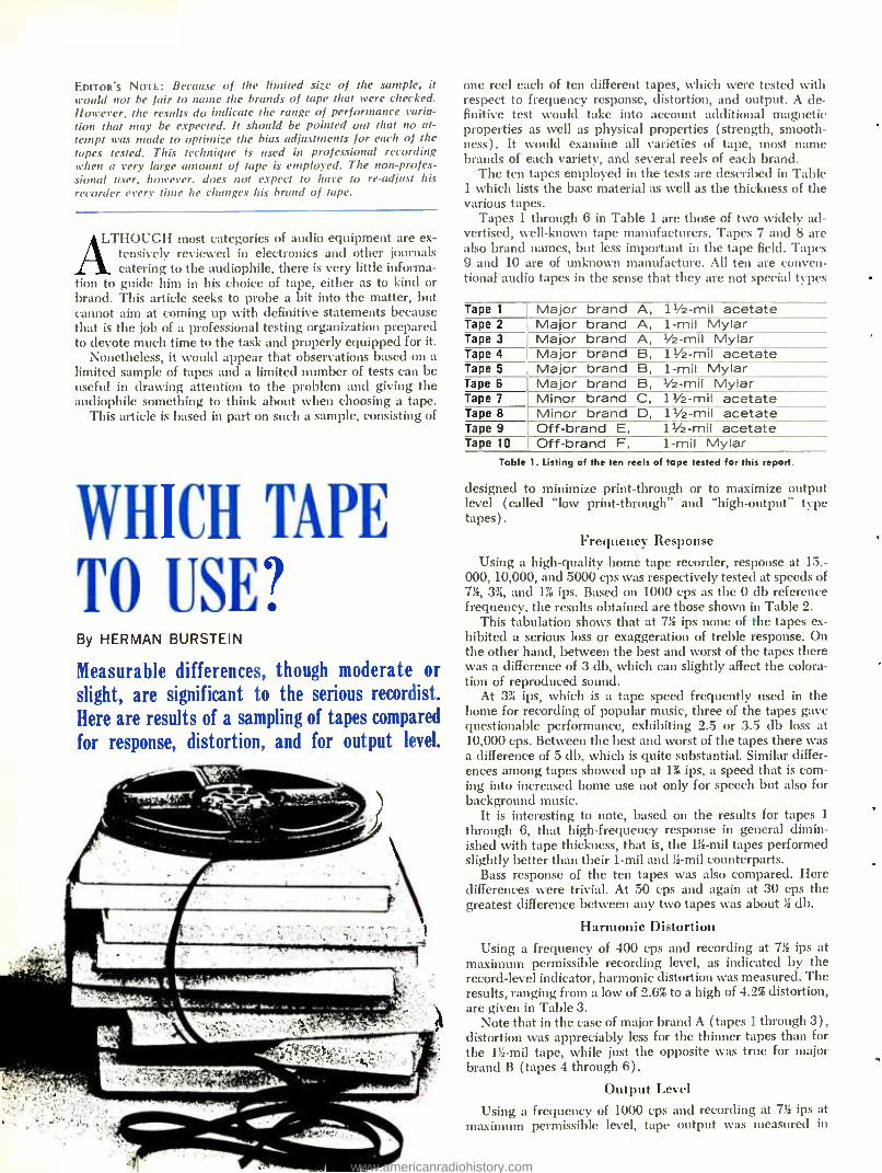
EDITOR'S NOTE: Because of the limited size of the sample, it would not be fair to name the brands of tape that were checked. However, the results do indicate the range of performance varia- tion that may be expected. It should be pointed out that no at- tempt was made to optimize the bias adjustments for each of the tapes tested. This technique is used in professional recording when a very large amount of tape is employed. The non- profes- sional user, however. does not expect to have to re- adjust his recorder every time he changes his brand of tape.
LTHOUGH most categories of audio equipment are ex- tensively reviewed in electronics and other journals catering to the audiophile, there is very little informa-
tion to guide him in his choice of tape, either as to kind or brand. This article seeks to probe a bit into the matter, but cannot aim at coming up with definitive statements because that is the job of a professional testing organization prepared to devote much time to the task and properly equipped for it.
Nonetheless, it would appear that observations based on a limited sample of tapes and a limited number of tests can be useful in drawing attention to the problem and giving the audiophile something to think about when choosing a tape.
This article is based in part on such a sample, consisting of
WHICH TAPE
TO USE? By HERMAN BURSTEIN
Measurable differences, though moderate or
slight, are significant to the serious recordist.
Here are results of a sampling of tapes compared
for response, distortion, and for output level.
one reel each of ten different tapes, which were tested with respect to frequency response, distortion, and output. A de- finitive test would take into account additional magnetic properties as well as physical properties ( strength, smooth- ness) . It would examine all varieties of tape, most name brands of each variety, and several reels of each brand.
The ten tapes employed in the tests are described in Table 1 which lists the base material as well as the thickness of the various tapes.
Tapes 1 through 6 in Table 1 are those of two widely ad- vertised, well -known tape manufacturers. Tapes 7 and 8 are also brand names, but less important in the tape field. Tapes 9 and 10 are of unknown manufacture. All ten are conven- tional audio tapes in the sense that they are not special types
Tape 1 Major brand A, 1112 -mil acetate Tape 2 Major brand A, 1 -mil Mylar Tape 3 Major brand A, 112 -mil Mylar Tape 4 Major brand B, 1112 -mil acetate Tape 5 Major brand B, 1 -mil Mylar Tape 6 Major brand B, 112 -mil Mylar Tape 7 Minor brand C, 1112 -mil acetate Tape 8 Minor brand D, 1112 -mil acetate Tape 9 Off -brand E, 1112 -mil acetate Tape 10 Off -brand F, 1 -mil Mylar
Table 1. Listing of the ten reels of tape tested for this report.
designed to minimize print -through or to maximize output level ( called "low print- through" and "high- output" type tapes) .
Frequency Response Using a high -quality home tape recorder, response at 15,-
000, 10,000, and 5000 cps was respectively tested at speeds of 7%, 3 %, and 1J ips. Based on 1000 cps as the 0 db reference frequency, the results obtained are those shown in Table 2.
This tabulation shows that at 7% ips none of the tapes ex- hibited a serious loss or exaggeration of treble response. On the other hand, between the best and worst of the tapes there was a difference of 3 db, which can slightly affect the colora- tion of reproduced sound.
At 3% ips, which is a tape speed frequently used in the home for recording of popular music, three of the tapes gave questionable performance, exhibiting 2.5 or 3.5 db loss at 10,000 cps. Between the best and worst of the tapes there was a difference of 5 db, which is quite substantial. Similar differ- ences among tapes showed up at 1% ips, a speed that is corn- ing into increased home use not only for speech but also for background music.
It is interesting to note, based on the results for tapes 1
through 6, that high -frequency response in general dimin- ished with tape thickness, that is, the 1% -mil tapes performed slightly better than their 1 -mil and % -mil counterparts.
Bass response of the ten tapes was also compared. Here differences were trivial. At 50 cps and again at 30 cps the greatest difference between any two tapes was about % db.
Harmonic Distortion
Using a frequency of 400 cps and recording at 7;i ips at maximum permissible recording level, as indicated by the record -level indicator, harmonic distortion was measured. The results, ranging from a low of 2.6% to a high of 4.2% distortion, are given in Table 3.
Note that in the case of major brand A (tapes 1 through 3), distortion was appreciably less for the thinner tapes than for the 1!s -mil tape, while just the opposite was true for major brand B (tapes 4 through 6) .
Output Level
Using a frequency of 1000 cps and recording at 7% ips at maximum permissible level, tape output was measured in
www.americanradiohistory.com
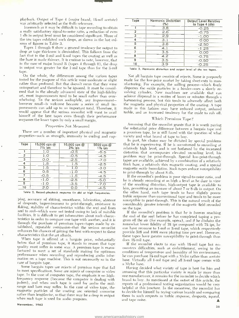
playback. Output of Tape 4 (major brand, 1% -mil acetate) was arbitrarily selected as the 0 -db reference.
Inasmuch as it may be difficult in tape recording to obtain a really satisfactory signal -to -noise ratio, a reduction of even 1 db in output level must be considered significant. Three of the ten tapes exhibited such drops, as shown in the last col- umn of figures in Table 3.
Tapes 1 through 6 show a general tendency for output to drop as tape thickness is diminished. This follows from the fact that in the 1 -mil and % -mil tapes the coating as well as the base is made thinner. It is curious to note, however, that in the case of major brand B (tapes 4 through 6), the drop in output was greater for the 1 -mil tape than for the is -mil tape.
On the whole, the differences among the various tapes tested for the purpose of this article were moderate or slight rather than profound. But that doesn't mean that they were unimportant and therefore to be ignored. It must be consid- ered that in the already advanced state of the high -fidelity art, most improvements tend to be small rather than over- whelming. To the serious audiophile, any improvement - however small -is welcome because a series of small im- provements can add up to an important total. Therefore, it would appear that the serious recordist will want to avail himself of the best tapes even though their performance surpasses the lesser tapes by only a small margin.
Properties Not Measured There are a number of important physical and magnetic
properties -such as strength, immunity to curling and cup-
Tape 15,000 cps @ 71 ips
10,000 cps @ 33/4 ips
5000 cps @ 1v /e ips
1 1.0 -0.5 -5.5 2 1.0 -0.5 -4.5 3 0.0 -2.5 -7.0 4 1.5 1.5 -2.5 5 1.5 1.0 -3.0 6 0.5 -1.0 -4.5 7 -0.5 -1.5 -4.5 8 -1.0 -2.5 -5.0 9 -1.0 -3.5 -7.0
10 2.0 0.0 -a R
Table 2. Record -playback response (in dbl at high frequencies.
ping, accuracy of slitting, smoothness, lubrication, absence of dropouts, imperviousness to print- through, resistance to flaking, stability of characteristics within the reel and from reel to reel -which were not tested owing to lack of suitable facilities. It is difficult to get information about such charac- teristics in order to compare one tape with another, and it is through the purchase of premium tapes -tapes made by es- tablished, reputable companies -that the serious recordist enhances his chances of getting the best with respect to these characteristics that the art affords.
Vhen tape is offered at a bargain price, substantially below that of premium tape, it stands to reason that tape quality must suffer in some way. A premium tape is manu- factured to meet a set of standards making for optimum performance when recording and reproducing audio infor- mation on a tape machine. This is not necessarily so in the case of bargain tape.
Some bargain tapes are rejects of premium tape that fail to meet specifications. Some are rejects of computer or video tape. In the case of computer tape, the emphasis is on high - frequency response (because the computer is dealing with pulses), and when such tape is used for audio the mid- range and bass may suffer. In the case of video tape, the magnetic particles of the coating are oriented crosswise rather than lengthwise, so that there may be a drop in output when such tape is used for audio purposes.
November, 1963
Tape Harmonic Distortion ( %)
Output Level Relative to Tape 4 (db)
1 3.8 -0.25 2 2.6 -0.75 3 2.9 -1.00 4 3.1 0.00 5 3.8 -2.50 6 4.1 -1.25 7 3.5 0.00 8 4.2 -0.75 9 3.5 -0.50 10 3.9 -0.25
Table 3. Harmonic distortion and output level of the ten tapes.
Not all bargain tape consists of rejects. Some is purposely made for the low -price market by taking short -cuts in man- ufacturing. For example, the milling process -which finely disperses the oxide particles in a binder -uses a slowly re- volving cylinder. New machines are available that can achieve dispersal in a matter of hours or minutes through a hammering process, but this tends to adversely affect both the magnetic and physical properties of the coating. A tape made in this fashion may have reduced output, reduced treble, and an increased tendency for the oxide to rub off.
Which Premium Tape? Assuming that the recordist grants that it is worth paying
the substantial price difference between a bargain tape and a premium tape, he is still faced with the question of what variety and what brand of tape to buy.
In part, his choice may be dictated by special problems that he is experiencing. If he is accustomed to recording at relatively high level, and is not bothered by the increased distortion that accompanies elevated recording level, his problem may be print- through. Special low- print- through tapes are available, achieved by a combination of a relatively thick base, a relatively thin magnetic coating, and a special magnetic oxide formulation. Such tapes reduce susceptibility to print -through by about 8 db.
If the recordist's problem is poor signal -to -noise ratio, and he is already recording at as high a level as he dare in view of the resulting distortion, high -output tape is available to him, permitting an increase of about 7 or 8 db in output. On the other hand, such tape tends to have slightly poorer treble response than conventional tape and tends to be more susceptible to print- through. This is the natural result of the considerably greater intensity of the magnetic field recorded on the tape.
If the recordist's problem is that he is forever reaching the end of the reel before he has completed taping a pro- gram off the air ( for example, opera) , and if he disdains the somewhat lower fidelity of 3% ips compared with 7% ips, he can have recourse to 1 -mil or % -mil tape, which respectively provide 50% and 100% more playing time per reel. However, these tapes have greater susceptibility to print- through than does 1%-mil tape.
If the recordist elects to stay with 11g -mil tape but en- counters difficulties, such as embrittlement, owing to the conditions of temperature and humidity of his environment, he can purchase 1% -mil tape with a Mylar rather than acetate base. Virtually all 1 -mil tape and all % -mil tape comes with a Mylar base.
Having decided what variety of tape is best for him and assuming that this particular variety is made by more than one manufacturer, it remains for the recordist to decide which brand to buy. As mentioned at the outset of this article, the reports of a professional testing organization would be very helpful at this juncture. In the meantime, the recordist has to decide for himself by trying various brands and comparing them in such respects as treble response, dropouts, squeal, and tape noise.
35
www.americanradiohistory.com
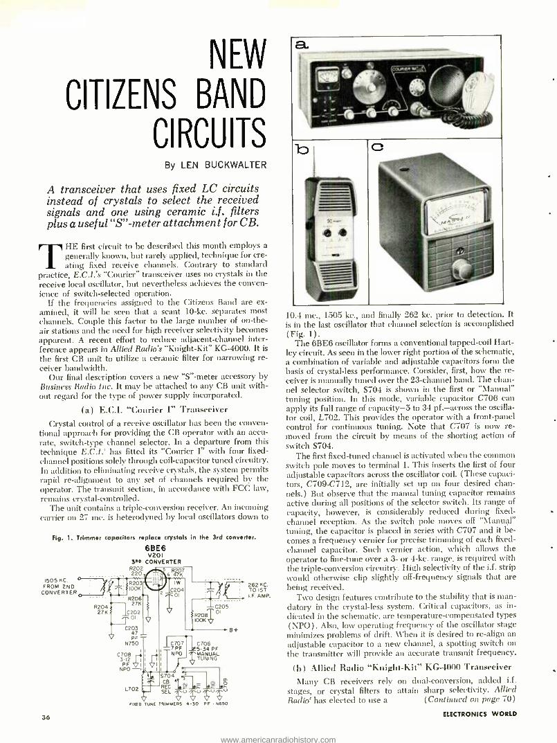
NEW
CITIZENS BAND
CIRCUITS By LEN BUCKWALTER
A transceiver that uses fixed LC circuits instead of crystals to select the received signals and one using ceramic i.f . filters plus a useful "S" -meter attachment for CB.
THE first circuit to be described this month employs a generally known, but rarely applied, technique for cre- ating fixed receive channels. Contrary to standard
practice, E.C.I.'s "Courier" transceiver uses no crystals in the receive local oscillator, but nevertheless achieves the conven- ience of switch- selected operation.
If the frequencies assigned to the Citizens Band are ex- amined, it will be seen that a scant 10 -ke. separates most channels. Couple this factor to the large number of on -the- air stations and the need for high receiver selectivity becomes apparent. A recent effort to reduce adjacent- channel inter- ference appears in Allied Radio's "Knight -Kit" KG -4000. It is
the first CB unit to utilize a ceramic filter for narrowing re- ceiver bandwidth.
Our final description covers a new "S" -meter accessory by Business Radio Inc. It may be attached to any CB unit with- out regard for the type of power supply incorporated.
(a) E.C.I. "Courier I" Transceiver Crystal control of a receive oscillator has been the conven-
tional approach for providing the CB operator with an accu- rate, switch -type channel selector. In a departure from this technique E.C.I.' has fitted its "Courier I" with four fixed - channel positions solely through coil -capacitor tuned circuitry. In addition to eliminating receive crystals, the system permits rapid re- alignment to any set of channels required by the operator. The transmit section, in accordance with FCC law, remains crystal- controlled.
The unit contains a triple- conversion receiver. An incoming carrier on 27 mc. is heterodyned by local oscillators down to
Fig. 1. Trimmer capacitors replace crystals in the 3rd converter.
1505 KC
FROM 2ND CONVERTER
36
6BE6 V20 I
3PD CONVERTER R202 220 7
R203 IOOK
5 6 R47K7
Iw C204
01
R204 27K
R206 27K
C202 01
C203 47 PF
N750
C708 i
3-12 V PF
I
NPO -r L702
FIFED TUNE
R208
C707 C706 7PF 5-34 PF NPO 1 TUÑIÑG
V
5704
RE CT T J: J!ñ J! Ó
SEL ;0; TRIMMERS 50 PF N650
216021 KC 5T
.
I.F. AMP.
C205 01
B+
10.4 me., 1505 kc., al d finally 262 kc. prior to detection. It is in the last oscillator that channel selection is accomplished (Fig. 1) .
The 6BE6 oscillator forms a conventional tapped -coil Hart- ley circuit. As seen in the lower right portion of the schematic, a combination of variable and adjustable capacitors form the basis of crystal -less performance. Consider, first, how the re- ceiver is manually tuned over the 23- channel band. The chan- nel selector switch, S704 is shown in the first or "Manual" tuning position. In this mode, variable capacitor C706 can apply its full range of capacity -5 to 34 pf.- across the oscilla- tor coil, L702. This provides the operator with a front -panel control for continuous tuning. Note that C707 is now re- moved from the circuit by means of the shorting action of switch S704.
The first fixed -tuned channel is activated when the common switch pole moves to terminal 1. This inserts the first of four adjustable capacitors across the oscillator coil. (These capaci- tors, C709 -C712, are initially set up on four desired chan- nels.) But observe that the manual tuning capacitor remains active during all positions of the selector switch. Its range of capacity, however, is considerably reduced during fixed - channel reception. As the switch pole moves off "Manual" tuning, the capacitor is placed in series with C707 and it be- comes a frequency vernier for precise trimming of each fixed - channel capacitor. Such vernier action, which allows the operator to fine -tune over a 3- or 4 -kc. range, is required with the triple -conversion circuitry. High selectivity of the i.f. strip would otherwise clip slightly off -frequency signals that are being received.
Two design features contribute to the stability that is man- datory in the crystal -less system. Critical capacitors, as in- dicated in the schematic, are temperature- compensated types (NPO). Also, low operating frequency of the oscillator stage minimizes problems of drift. When it is desired to re -align an adjustable capacitor to a new channel, a spotting switch on the transmitter will provide an accurate transmit frequency.
(b) Allied Radio "Knight -Kit" KG -4000 Transceiver
Many CB receivers rely on dual -conversion, added i.f. stages, or crystal filters to attain sharp selectivity. Allied Radio` has elected to use a (Continued on page 70)
ELECTRONICS WORLD
www.americanradiohistory.com
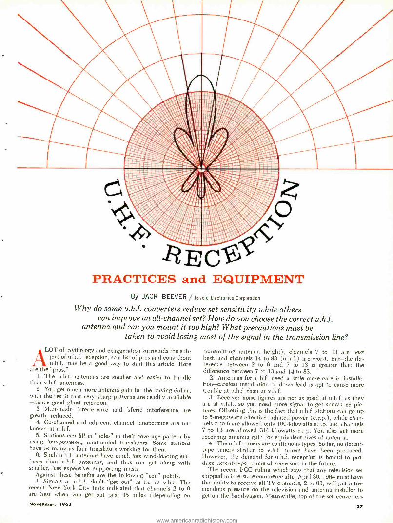
PRACTICES and EQUIPMENT By JACK BEEVER / Jerrold Electronics Corporation
Why do some u.h.f. converters reduce set sensitivity while others can improve an all -channel set? How do you choose the correct u.h.f .
antenna and can you mount it too high? What precautions must be taken to avoid losing most of the signal in the transmission line?
LOT of mythology and exaggeration surrounds the sub- ject of u.h.f. reception, so a list of pros and cons about u.h.f. may be a good way to start this article. Here
are the "pros." 1. The u.h.f. antennas are smaller and easier to handle
than v.h.f. antennas. 2. You get much more antenna gain for the buying dollar,
with the result that very sharp patterns are readily available -hence good ghost rejection.
3. Man -made interference and 'sferic interference are greatly reduced.
4. Co- channel and adjacent channel interference are un- known at u.h.f.
5. Stations can fill in "holes" in their coverage pattern by using low -powered, unattended translators. Some stations have as many as four translators working for them.
6. Such u.h.f. antennas have much less wind- loading sur- faces than v.h.f. antennas, and thus can get along with smaller, less expensive, supporting masts.
Against these benefits are the following "con" points. 1. Signals at u.h.f. don't "get out" as far as v.h.f. The
recent New York City tests indicated that channels 2 to 6 are best when you get out past 45 miles (depending on
November, 1963
transmitting antenna height), channels 7 to 13 are next best, and channels 14 to 83 (u.h.f.) are worst. But -the dif- ference between 2 to 6 and 7 to 13 is greater than the difference between 7 to 13 and 14 to 83.
2. Antennas for u.h.f. need a little more care in installa- tion- careless installation of down -lead is apt to cause more trouble at u.h.f. than at v.h.f.
3. Receiver noise figures are not as good at u.h.f. as they are at v.h.f., so you need more signal to get snow -free pic- tures. Offsetting this is the fact that u.h.f. stations can go up to 5- megawatts effective radiated power (e.r.p.), while chan- nels 2 to 6 are allowed only 100- kilowatts e.r.p. and channels 7 to 13 are allowed 316 -kilowatts e.r.p. You also get more receiving antenna gain for equivalent sizes of antenna.
4. The u.h.f. tuners are continuous types. So far, no detent- type tuners similar to v.h.f. tuners have been produced. However, the demand for u.h.f. reception is bound to pro- duce detent -type tuners of some sort in the future.
The recent FCC ruling which says that any television set shipped in interstate commerce after April 30, 1964 must have the ability to receive all TV channels, 2 to 83, will put a tre- mendous pressure on the television and antenna installer to get on the bandwagon. Meanwhile, top -of- the -set converters
37
www.americanradiohistory.com
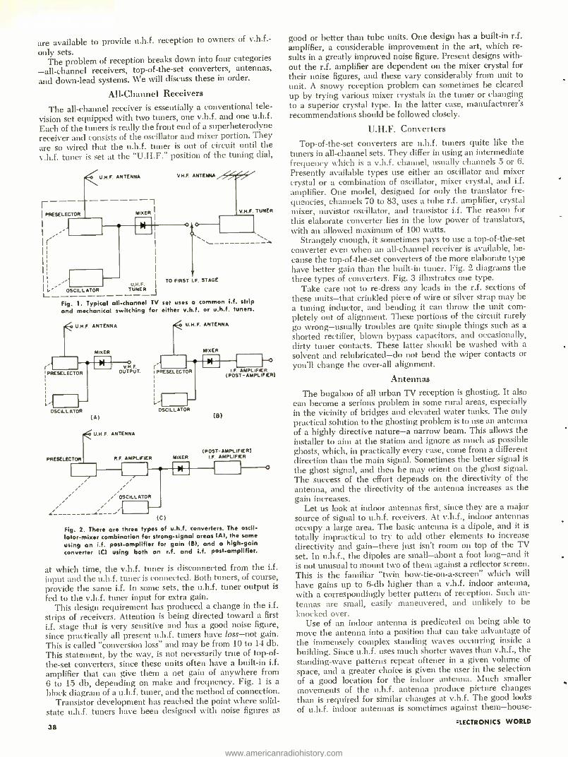
are available to provide u.h.f. reception to owners of v.h.f.-
only sets. The problem of reception breaks down into four categories
-all- channel receivers, top -of- the -set converters, antennas,
and down -lead systems. We will discuss these in order.
All -Channel Receivers
The all- channel receiver is essentially a conventional tele- vision set equipped with two tuners, one v.h.f. and one u.h.f.
Each of the tuners is really the front end of a superheterodyne receiver and consists of the oscillator and mixer portion. They are so wired that the u.h.f. tuner is out of circuit until the v.h.f. tuner is set at the "U.H.F." position of the tuning dial,
-- PRE$ELECTOR
f
U.M.F. ANTENNA VHF. ANTENNA
---, MIXE
OSCILLATOR U.N.F.
TUNER j
TO FIRST
V.M.F. TUNER
F. STAGE
Fig. 1. Typical all- channel TV set uses a common i.f. strip
and mechanical switching for either v.h.f. or u.h.f. tuners.
UHF ANTENNA
MIXER
PRESELECTOR
OSCILLATOR (A)
PRESELECTOR
V.N.F. OUTPUT.
U.N.F. ANTENNA
U N F. ANTENNA
MIXER
PRESELECTOR IF AMPLIFIER (POST - AMPLIFIER)
OSCILLATOR (B)
(POST- AMPLIFIER) R AMPLIFIER MIXER I.F. AMPLIFIER
OSCILLATOR
(C)
Fig. 2. There are three types of u.h.f. converters. The oscil- lator -mixer combination for strong -signal areas IA), the same
using an i.f. post -amplifier for gain IBI, and a high -gain converter ICI using both an r.f. and i.f. post -amplifier.
at which time, the v.h.f. tuner is disconnected from the ii. input and the u.h.f. tuner is connected. Both tuners, of course, provide the same i.f. In some sets, the u.h.f. tuner output is
fed to the v.h.f. tuner input for extra gain. This design requirement has produced a change in the i.f.
strips of receivers. Attention is being directed toward a first
i.f. stage that is very sensitive and has a good noise figure, since practically all present u.h.f. tuners have loss -not gain. This is called "conversion loss" and may be from 10 to 14 db. This statement, by the way, is not necessarily true of top -of-
the -set converters, since these units often have a built -in i.f.
amplifier that can give them a net gain of anywhere from 6 to 15 db, depending on make and frequency. Fig. 1 is a block diagram of a u.h.f. tuner, and the method of connection.
Transistor development has reached the point where solid - state u.h.f. tuners have been designed with noise figures as
38
good or better than tube units. One design has a built -in r.f.
amplifier, a considerable improvement in the art, which re- sults in a greatly improved noise figure. Present designs with- out the r.f. amplifier are dependent on the mixer crystal for their noise figures, and these vary considerably from unit to unit. A snowy reception problem can sometimes be cleared up by trying various mixer crystals in the tuner or changing to a superior crystal type. In the latter case, manufacturer's recommendations should be followed closely.
U.H.F. Converters
Top -of- the -set converters are u.h.f. tuners quite like the tuners in all -channel sets. They differ in using an intermediate frequency which is a v.h.f. channel, usually channels 5 or 6.
Presently available types use either an oscillator and mixer crystal or a combination of oscillator, mixer crystal, and i.f. amplifier. One model, designed for only the translator fre- quencies, channels 70 to 83, uses a tube r.f. amplifier, crystal mixer, nuvistor oscillator, and transistor i.f. The reason for
this elaborate converter lies in the low power of translators, with an allowed maximum of 100 watts.
Strangely enough, it sometimes pays to use a top -of- the -set converter even when an all- channel receiver is available, be- cause the top -of- the -set converters of the more elaborate type have better gain than the built -in tuner. Fig. 2 diagrams the three types of converters. Fig. 3 illustrates one type.
Take care not to re -dress any leads in the r.f. sections of
these units -that crinkled piece of wire or silver strap may be a tuning inductor, and bending it can throw the unit com- pletely out of alignment. These portions of the circuit rarely go wrong -usually troubles are quite simple things such as a shorted rectifier, blown bypass capacitors, and occasionally, dirty tuner contacts. These latter should be washed with a
solvent and relubricated -do not bend the wiper contacts or you'll change the over -all alignment.
Antennas
The bugaboo of all urban TV reception is ghosting. It also can become a serious problem in some rural areas, especially in the vicinity of bridges and elevated water tanks. The only practical solution to the ghosting problem is to use an antenna of a highly directive nature -a narrow beam. This allows the installer to aim at the station and ignore as much as possible ghosts, which, in practically every case, come from a different direction than the main signal. Sometimes the better signal is
the ghost signal, and then he may orient on the ghost signal. The success of the effort depends on the directivity of the antenna, and the directivity of the antenna increases as the gain increases.
Let us look at indoor antennas first, since they are a major source of signal to u.h.f. receivers. At v.h.f., indoor antennas occupy a large area. The basic antenna is a dipole, and it is
totally impractical to try to add other elements to increase directivity and gain -there just isn't room on top of the TV set. In u.h.f., the dipoles are small -about a foot long -and it is not unusual to mount two of them against a reflector screen. This is the familiar "twin bow- tie -on -a- screen" which will have gains up to 6 -db higher than a v.h.f. indoor antenna, with a correspondingly better pattern of reception. Such an- tennas are small, easily maneuvered, and unlikely to be knocked over.
Use of an indoor antenna is predicated on being able to move the antenna into a position that can take advantage of
the immensely complex standing waves occurring inside a
building. Since u.h.f. uses much shorter waves than v.h.f., the standing -wave patterns repeat oftener in a given volume of
space, and a greater choice is given the user in the selection of a good location for the indoor antenna. Much smaller movements of the u.h.f. antenna produce picture changes than is required for similar changes at v.h.f. The good looks
of u.h.f. indoor antennas is sometimes against them -house-
= LECTRONICS WORLD
www.americanradiohistory.com
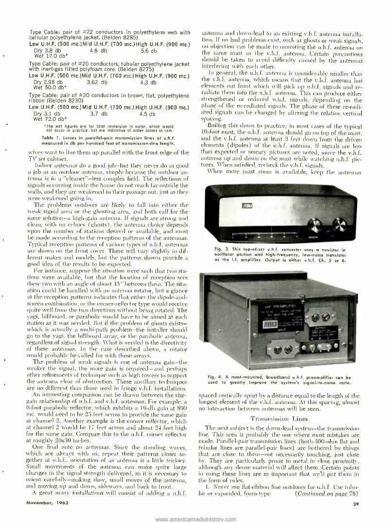
Type Cable: pair of =22 conductors in polyethylene web with cellular polyethylene jacket. (Belden 8285) Low U.H.F. (500 mc.)Mid U.H.F. (700 mc.)High U.H.F. (900 mc.)
Dry 3.8 db 4.8 db 5.6 db Wet 17.0 db*
Type Cable: pair of =20 conductors, tubular polyethylene jacket with inert -gas filled polyfoam core. (Belden 8275) Low U.H.F. (500 mc.)Mid U.H.F. (700 mc.) High U.H.F. (900 mc.)
4.3 db Dry 2.98 db 3.62 db Wet 50.0 db*
Type Cable: pair of =20 conductors in brown, flat, polyethylene ribbon (Belden 8230) Low U.H.F. (500 mc.)Mid U.H.F. (700 mc.) High U.H.F. (900 mc.)
Dry 3.1 db 3.7 db 4.5 db Wet 72.0 db*
*The wet figures are for total immersion in water, which would not occur in practice, but are indicative of water losses in rain.
Table 1. Losses in parallel -pair transmission lines at u.h.f. measured in db per hundred feet of transmission -line length.
wives want to line them up parallel with the front edge of the TV set cabinet.
Indoor antennas do a good job -but they never do as good a job as an outdoor antenna, simply because the outdoor an- tenna is in a "cleaner" -less complex field. The reflections of signals occurring inside the house do not reach far outside the walls, and they are weakened in their passage out, just as they were weakened going in.
The problems outdoors are likely to fall into either the weak signal area or the ghosting area, and both call for the same solution -a high -gain antenna. if signals are strong and clean, with no echoes (ghosts), the antenna choice depends upon the number of stations desired or available, and must be made according to the reception patterns of the antennas. Typical reception patterns of various types of u.h.f. antennas are shown on the front cover. These will vary slightly in dif- ferent makes and models, but the patterns shown provide a good idea of the results to be expected.
For instance, suppose the situation were such that two sta- tions were available, but that the location of reception sees these two with an angle of about 45 between them. The situ- ation could be handled Nvith an antenna rotator, but a glance at the reception patterns indicates that either the dipole -and- screen combination, or the corner -reflector type would receive quite well from the two directions without being rotated. The yagi, billboard, or parabolic would have to be aimed at each station as it was needed. But if the problem of ghosts exists - which is actually a multi -path problem -the installer should go to the yagi, the billboard array, or the parabolic antenna, regardless of signal strength. What is needed is the directivity of these antennas. In the case described above, a rotator would probably be called for with those arrays.
The problem of weak signals is one of antenna gain -the weaker the signal, the more gain is required -and perhaps other refinements of technique such as high towers to support the antenna clear of obstruction. These ancillary techniques are no different than those used in fringe v.h.f. installations.
An interesting comparison can be drawn between the size - gain relationship of u.h.f. and v.h.f. antennas. For example, a 6 -foot parabolic reflector, which exhibits a 19 -db gain at 890 mc. would need to be 25 feet across to provide the same gain at channel 2. Another example is the corner reflector, which at channel 2 would be 17 feet across and about 24 feet high for the same gain. Compare this to the u.h.f. corner reflector at roughly 20x30 inches.
One final note on antennas. Since the standing waves, which are always with us, repeat their patterns closer to- gether at u.h.f., orientation of an antenna is a little trickier. Small movements of the antenna can make quite large changes in the signal strength delivered, so it is necessary to orient carefully- making slow, small moves of the antenna, and moving up and down, sideways, and back to front.
A great many installations will consist of adding a u.h.f.
November, 1963
antenna and down -lead to an existing v.h.f. antenna installa- tion. If no bad problems exist, such as ghosts or weak signals, no objection can be made to mounting the u.h.f. antenna on the same mast as the v.h.f. antenna. Certain precautions should be taken to avoid difficulty caused by the antennas interfering with each other.
In general, the u.h.f. antenna is considerably smaller than the v.h.f. antenna, which means that the v.h.f. antenna has elements out front which will pick up u.h.f. signals and re- radiate them into the u.h.f. antenna. This can produce either strengthened or reduced u.h.f. signals, depending on the phase of the re- radiated signals. The phase of these re -radi- ated signals can be changed by altering the relative vertical spacing.
Boiling this down to practice, in most cases of the typical 10 -foot mast, the u.h.f. antenna should go on top of the mast, and the v.h.f. antenna at least 3 feet down from the driven elements (dipoles) of the u.h.f. antenna. If signals are less than expected or smeary pictures are noted, move the v.h.f. antenna up and down on the mast while watching u.h.f. pic- tures. When satisfied, recheck the v.h.f. signals.
«'hen more mast room is available, keep the antennas
Fig. 3. This top -of -set u.h.f. converter uses a nuvistor in oscillator portion and high- frequency, low -noise transistor as the i.f. amplifier. Output is either v.h.f. Ch. 5 or 6.
Ulf PREASpt.IFlEh
^.M 0'SS YODa..r.-,U., tDY. pDr WIC OM
Wri .r,,.;
OWL. 110
spun
Fig. 4. A mast -mounted, broadband u.h.f. preamplifier can be used to greatly improve the system's signal -to -noise ratio.
spaced vertically apart by a distance equal to the length of the longest element of the v.h.f. antenna. At this spacing, almost no interaction between antennas will be seen.
Transmission Lines The next subject is the down -lead system -the transmission
line. This area is probably the one where most mistakes are made. Parallel -pair transmission lines (both 300 -ohm flat and tubular lines are parallel -pair lines) are bothered by things that are close to them -not necessarily touching, just close by. They are particularly prone to metal in close proximity, although any dense material will affect them. Certain points in using these lines are so important that we'll put them in the form of rules.
1. Never use flat -ribbon line outdoors for u.h.f. Use tubu- lar or expanded, foam -type (Continued on page 78)
39
www.americanradiohistory.com
ELECTRONICS LAB
TECHNICIAN: HIS ROLE IN INDUSTRY By CYRUS GLICKSTEIN
What are the duties, responsibilities, requirements, and salary ranges for this important job in our R & D labs?
TI1E amazing growth ul the electronics industry in
recent years has been sparked by the outstanding achievements of scientists and engineers in the R &D
research and development) laboratories of our nation. \Forking side by side with engineers, laboratory technicians have also contributed substantially to progress in the in-
dustry. Engineers generally agree that lab technicians serve a vital function on the R &D team.
The laboratory technician is far from being just a handy man with a soldering iron who assembles circuits on a bread - board at the direction of an engineer.
Exactly what are the functions of a laboratory technician in an electronics manufacturing firm? What qualifications are expected of him when he applies for his first job and later on, when he is more experienced? What are the possibilities for advancement? What particular satisfactions does the job offer?
Most large- and medium -sized firms produce a variety of electronic equipment, while smaller firms tend to be more specialized in their output. The specific area of electronics the technician works in depends on the company he works for and the department and section within the firm to which he is assigned. The lab technician, therefore, may be assigned to a project in any one of the following fields: space elec- tronics, radar, navigation or communications equipment, computers, antennas, industrial electronics, ultrasonics, TV transmitters or receivers, test instruments, automatic con- trols, medical electronics, nucleonics, or any other area of specialization covered by his firm. The lab technician may be assigned to either a military or commercial R &D program. If the firm does a substantial amount of military business, a
number of projects may be classified and the technician Neill
probably be required to obtain a security clearance. Lab technicians function under a number of different titles,
which may vary from company to company. Some of the more familiar job titles are: laboratory technician, electronics technician, R &D technician, and development technician. While there may be some differences in the specific duties assigned to a lab technician in various companies, the follow- ing is a generalized description of his activities.
The main duties of the lab technician consist of bread- boarding; constructing experimental, prototype, and similar models of equipment; debugging; and testing. He may also be required to perform various paper chores such as requisi- tioning supplies, running curves, drawing up schematic and other diagrams, keeping test and other records, and helping to formulate specifications and handbook data.
Types of Projects
The company assigns a new project to the section con- cerned with that type of program. Within the section, the project is assigned to at least one team, consisting of engi-
40
'leers and lab technicians with a project engineer in charge. In addition to R &D projects which have new or improved
hardware as the end item, a firm may undertake study pro- grams under contract to various government agencies and private organizations. These programs are generally pre- liminary studies of the feasibility of new circuits or an analy- sis in depth of a whole area of activity prior to determining the feasibility of new types of equipment.
If the project is a small one -for example a study program to determine the feasibility of a parametric amplifier in a
frequency range higher than has yet been achieved -one team may be assigned. In this type of program, the lab technician's main duties would consist of breadboarding various circuits under the supervision of engineers, checking known and new types of circuit components and circuit arrangements, making measurements, running tests, plotting curves, and similar duties. Where called for, he will usually do most of the construction of the final breadboard which demonstrates the feasibility of the newly developed circuit.
If the project is a large one, a number of teams are used, each assigned to a key portion of the project, again with one project engineer in charge of the over -all program.
Program Phases
A large project involving the development of a complex piece of new equipment entails several phases. For example, a typical program for one of the armed services may call for a number of production units of the equipment as the end item, but the contract may also require several preliminary units to be developed, fabricated, and tested by the R &D
teams. These preliminary phases will assure that the final units for field use will have the optimum design and maximum reliability that can be engineered into the equipment within the time limits specified for the program. In many cases a
crash program is involved including the following: 1. Breadboard model. This consists of a breadboard of the
entire system, after breadboards of all of the component sub- assemblies have been built and tested, to determine if the equipment can perform as required. The appearance and design of the breadboard version need not approximate the final production model.
2. Experimental (XPJ1) model. This model of the final
equipment is used to demonstrate the technical soundness of the basic idea. This model does not have to have the re-
quired final form or necessarily contain parts of final design. 3. Service test model (STM). This model is used for testing
under service conditions for evaluation of suitability and performance. It must closely approximate the final design, have the required form, and use approved parts or inter- changeable equivalents. After an STM is completed, it may be given various environmental tests (vacuum, heat, hu- midity, cold, vibration, etc.) and delivered to the contracting
ELECTRONICS WORLD
www.americanradiohistory.com
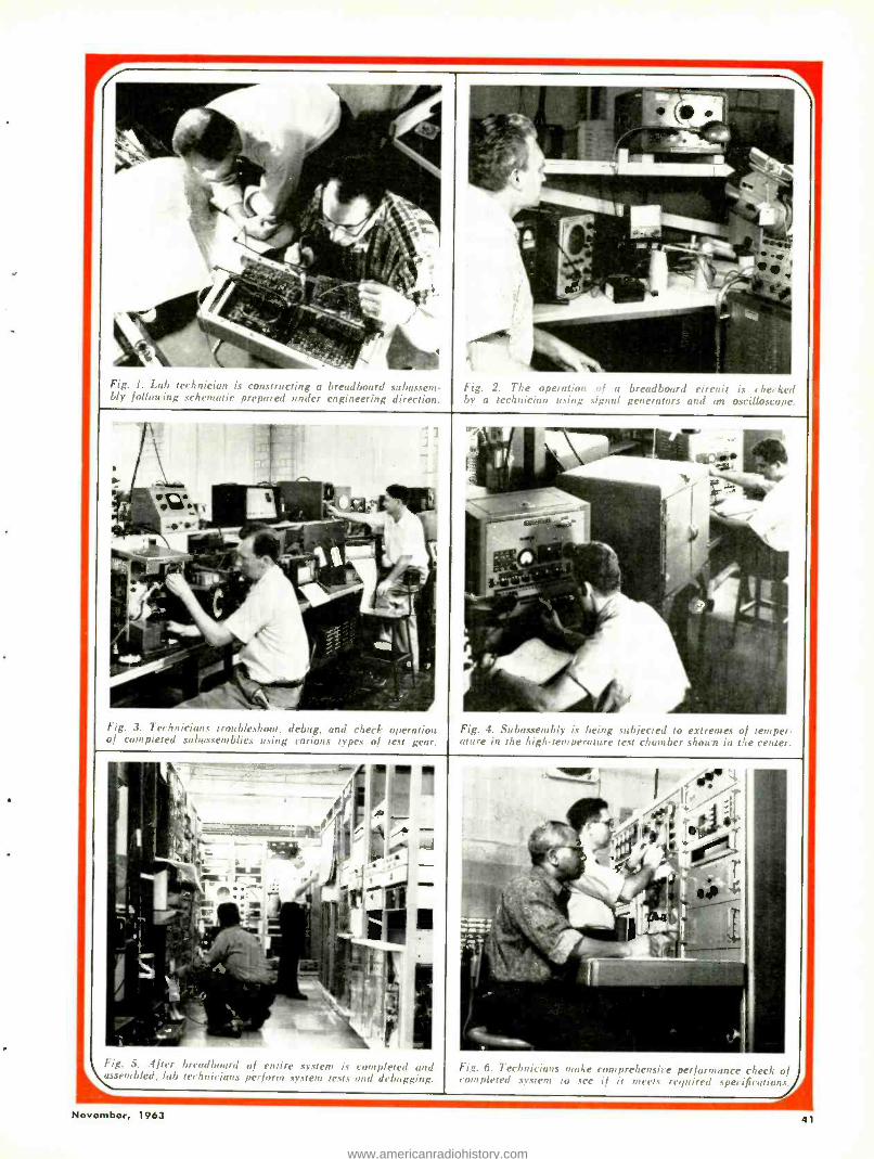
Fig. 1. Lab technician is constructing a breadboard subassem- bly following schematic prepared under engineering direction.
Fig. 2. The operation of a breadboard circuit is checked by a technician using signal generators and an oscilloscope.
Fig. 3. Technicians troubleshoot. d, mg, and check operation of completed subassemblies using various types of test gear.
Fig. t. ,;41,,o.c1,1bly is being subjected to extremes of temper- ature in the high -temperature rest chamber shown in the center.
Fig. .5. After headboard of entire system is completed and
hi, `auemblet!. lab technicians perform system tests and debugging.
Fig. u.. Technicians rao/e comprehensive performance check of completed system to see if it meets required specifications.
November, 1963 41
www.americanradiohistory.com

agency for test under various field conditions. As a result of these environmental and field tests, certain changes may be incorporated in subsequent models.
4. Prototype (pre -production) model. This model is suit- able for making a complete evaluation of mechanical and electrical form, design, and performance. It must be of final mechanical and electrical form, use approved parts, and be representative of the equipment in its final form.
After approval by the customer, the prototype model is
turned over to the production department which then fabri- cates production units. These incorporate final mechanical and electrical design changes and are made by production tools, jigs, fixtures, and methods, as applicable. In some cases, when the production runs are small and the equipment par- ticularly complex, these production units may be turned over to the original R &D teams for final alignment and system testing prior to delivery.
R &D teams in larger projects involving military equipment are concerned essentially with the following models: bread- boards, XPM's, STM's, and prototypes. R &D projects for commercial equipment generally involve fewer models be- tween the breadboard and prototype stages.
In the initial design stages of the project, the broad lines of approach are laid down by the engineering groups in- volved- design, project, and staff engineers and various de- partment consultants, while reliability engineers may pass on the reliability aspects of preliminary designs. In many cases, preliminary designs must be accepted by the customer before further development proceeds. The preliminary de- sign on paper is based on past experience with similar circuits or on what is considered to be the most likely approach to new or radically different circuitry.
Technician's Duties
After the initial design has been accepted by the customer, breadboarding begins. See Fig. 1. Here, most of the actual work of constructing the breadboard version is done by the lab technician. He follows the schematic diagrams provided by the engineer, draws the necessary parts from the stock- room, solders circuits together where necessary, and checks as he goes along to determine if the circuit is operating as specified by the engineer in charge. Fig. 2. If not, he makes further checks, using appropriate test equipment, to deter- mine if the circuit is wired up incorrectly or some part is
defective. Depending on his qualifications, he may also test the effects of changes in some component values before reporting the results to the engineer. For breadboarding, the technician must know how to read schematic diagrams, have some degree of specialized knowledge in the area of elec- tronics in which he is working, have a good knowledge of circuit behavior, and be familiar with construction and soldering.
At various points in the program, the lab technician may be required to run various operational and performance tests on the sub -assemblies (Figs. 3 and 4) and on the completed breadboard to determine if the equipment is operating cor- rectly. In performing these tests, the technician may be called upon to use such test equipment as oscilloscopes, v.t.v.m.'s, digital voltmeters, power meters, counters, signal generators, and bridges. Tests may cover everything from an operational check of each step in firing up the equipment and verifying the operation of each control to measuring precise per- formance parameters including frequency, power output, selectivity and image rejection, distortion, s.w.r., noise figure, and similar characteristics.
In making such measurements, the technician must be fa- miliar with various types of test equipment, know how to make such tests accurately, and how to record the results cor- rectly. In many cases he will be expected to know when the test results indicate that the circuit is not operating properly and be able to report on the probable cause of the difficulty.
Debugging is an important part of developing new de- signs. When subassemblies are interconnected and tested, the circuit may not operate as planned. See Fig. 5. The cause may be one or more of the following: an incorrect connection, a defective part, unexpected interactions between circuits, complications introduced by loading, parts values which must be changed either because cumulative tolerances have af- fected operation, or for a number of other reasons. In debug- ging, the technician first tracks down the general cause of the difficulty, using test equipment if necessary. If the trouble is simple -such as a defective part -he makes the repair and re -tests the circuit. In more complex problems, where re- design may be involved, he makes circuit changes under the supervision and direction of the engineer in charge.
After the breadboard model is completed, tested, and ac- cepted, the other models are constructed in turn. In each case, circuits are completed, tested, and debugged as neces- sary. Fig. 6. It is often discovered that in transforming a breadboard design into a more sophisticated model, new problems arise due to the use of new parts, differences in parts placement, space and weight limitations, and miscel- laneous causes. Also, as the program proceeds, the customer may request changes in the original design to extend the capabilities of the unit; thus additional development work may be required as later laboratory models are constructed. The prototype model generally incorporates final design changes before a production run is started. However, because of the pace of new developments in electronics, additional design changes may be required in completed production units to improve or extend equipment performance.
At various points in the activities outlined thus far, the lab technician may be involved in different types of paper work. He may, on occasion, be asked to draw neat schematic, block, interconnection, or other kinds of diagrams for use by the drafting department as a guide for final drawings. He will usually record results of various tests covering performance parameters on appropriate data sheets, draw graphs when necessary, and assist engineers in providing technical writers with operation and maintenance data for use in reports and instruction manuals to go with the equipment.
Job Requirements What are the requirements for a job as a lab technician?
Many firms employ three grades of technicians -"A," "B," and "C," with "A" indicating the highest grade. Hiring may be done on all three levels, as dictated by personnel require- ments at a given time. The job applicant is usually screened by the personnel department interviewer, then may be inter- viewed by an engineer from the department making the job request. In general, the following qualifications are expected of the applicant:
1. Lab Technician Grade "C." High school graduate plus technical training, such as a two -year electronics technology course, plus 1 to 3 years of qualifying experience, or an equivalent combination of these three requirements. The applicant will usually be tested on his technical knowledge.
2. Lab Technician Grade "B." High school graduate plus two years of college or equivalent plus 3 to 5 years of closely related experience. He must be familiar with specific types of test equipment, know how to use these in various electronic circuits, be familiar with laboratory procedures and construc- tion practices, and have some specific knowledge of the area of specialization in which he will work (r.f. circuitry, digital circuits, radar, etc.). He can be expected to answer special- ized technical questions.
3. Lab Technician Grade "A." High school graduate plus two years of college or equivalent plus 5 to 7 years of experi- ence. Some recognition is given to specialized experience as a ham operator, FCC licensee, TV bench technician, Armed Forces electronics technician, but major experience is ex- pected in laboratory Nvork and in (Continued on page 81)
42 ELECTRONICS WORLD
www.americanradiohistory.com

PHASEMETER
FOR
AUDIO FREQUENCIES By THOMAS E. REAMER
Phase distortion in audio impair the quality of the laboratory -type phasemeter the amount and direction
THE instrument described in this article measures the phase angle between an unknown voltage and a refer- ence voltage of the same frequency at audio and ultra-
sonic ranges between 20 cps and 50 kc., and at voltage inputs from 0.5 volt to 60 volts r.m.s. without adjustment. The meter is calibrated from 0° (360" ) to 180' full -scale and is accurate to -±3° of phase shift in the audio range. A 0 -18' full -scale range may be switch selected, and a phase shift direction cir- cuit indicates the input with the leading phase angle. Phase readings may be made with much greater rapidity than with an oscilloscope and are generally more precise, especially at angles near o- and 180'. The phase angle between wave- forms such as saw- tooth, triangular, and square may also be determined; a difficult task with an oscilloscope.
Phase angle measurements are of significance when evalu- ating the performance of amplifiers, preamplifiers, crossover networks, transformers, loudspeakers, filters, and attenuators. The phase shift of low- and high -pass filters in multiplex cir- cuitry is of recent interest. Several of these applications are discussed in some detail later in this article.
Phase -Shift Definition Phase shift may occur when reactive elements (inductors
or capacitors) are in the circuit. Reactive capacitances may cause a phase delay, i.e., the output voltage from the circuit lags behind the input voltage. Reactive inductances may re- sult in the output voltage leading the input voltage. These effects are shown in Fig. 1A.
Fig. 1. (Al Phase shift resulting from capacitive and inductive reactance, (B) determination of phase angle from a Lissa - jous pattern, and ICI balanced modulator phase -measurement.
SIN e= (A)
(B) (C)
November, 1963
equipment can seriously reproduced sound. This
can be used to determine of any phasing errors.
Phase shift may be defined as the displacement in degrees, e, of like zero -axis crossings of the reference and unknown voltages. If this definition is accepted, the indicated phase shift is correct even in the case where the reference voltage is a sine wave and the unknown voltage is a harmonically distorted wave.
The oscilloscope is a versatile and widely used instrument for the measurement of phase angle. A high -quality, dual - trace instrument can be used to display both the reference wave and the unknown waveform. Measurement of the dis- placement of the peaks of the two traces will indicate directly the phase angle. A spiral sweep circuit for use with an oscillo- scope was devised by K. S. Lion and J. Goodman.' Two spikes radiate from the small circular sweep on the oscilloscope screen. Measurement of the angle between the spikes indi- cates the phase angle. Other techniques involving Z -axis trace blanking of a spiral sweep have been described.2
Lissajous figures, named after Jules Antoine Lissajous who first observed them with a pendulum forming a trace in sand, are a generally used oscilloscope procedure for the meas- urement of phase angle. The scope internal sweep is turned off and the two input signals directed to the vertical and hori- zontal inputs. The distances shown in Fig. 1B are measured and the phase angle, e, determined with the aid of a sine table.
The method is limited to distortionless sine waves and the measurements must be carefully made, preferably from a photograph. The internal phase shift of the Vertical and hori-
Fig. 2. The two series of square waves from each input chan- nel are combined in a dual -grid tube so that any phase dif- ference can be measured on meter calibrated in degrees shift.
A B C
"Ar V Flu EEr 1
'ER kJ-, A CLIPP INPUT
ER
AMPLIFIER CLIPPER
V2
SCHMITT TRIG. CNT.
VS
o
.o
V7 PLATE
VOLTAGE
u
V7 PLATE
CURRENT
n
s y_ -
ADDITION SWITCH o lao.
o IA.
M
DIRECTION DEL Av
COMBINING TUBE
V7
AMPLIFIER CLIPPER
V4
AMPLIFIER CLIPPER
VS
SCNMITT TRIG CAT
V6 INPUT
E
\/ V F G
43
www.americanradiohistory.com
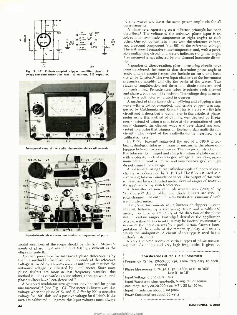
9.1K
43K
(01 EIl
Fig. 3. (A) Cathode -coupled clipper amplifier circuit. (BI Phase standard circuit uses four 1 resistors, 5 °b capacitor.
Front -panel view of the audio phasemeter shows all controls.
C22,23,24 VS OF! V9 ,.
C7,15, 2I
V6 - Rss
V6
- R46
V4
R36 SS
R68
S1 R70 METER R71
Top -of- chassis view shows mechanical arrangement of parts.
zontal amplifiers of the scope should be identical. Measure- ments of phase angle near 0° and 180° are difficult as the ellipse is quite flat.
Another procedure for measuring phase difference is by the null method.2 The phase and amplitude of the reference voltage is varied by a known amount until it just matches the unknown voltage as indicated by a null meter. Since most phase shifters are more or less frequency sensitive, this method is not as versatile as some others, although wide -band phase shifters have been described.2
A balanced modulator arrangement may be used for phase measurement2,3 (see Fig. 1C). The meter indicates zero d.c. voltage when the phase of E1 and E2 differ by 90 °, a negative voltage for 180' shift and a positive voltage for 0° shift. If the meter is calibrated in degrees, the input voltages must always
44
be sine waves and have the same preset amplitude for all measurements.
A phasemeter operating on a different principle has been described.4 The voltage of the unknown phase input is re- solved into two basic components at right angles to each other. One component is in phase with the reference voltage, and a second component is at 90° to the reference voltage. The instrument separates these components and, with a preci- sion multiplying circuit and meter, indicates the phase angle. Measurement is not affected by one -channel harmonic distor- tion.
A number of direct- reading, phase- measuring circuits have been developed. Instruments that determine phase angle at audio and ultrasonic frequencies include an early and basic design by Ginzton.s The two input channels of the instrument successively amplify and clip the peaks of the waves. Two stages of amplification and three dual diode tubes are used for each input. Pentode sum tubes terminate each channel and share a common plate resistor. The voltage drop is meas- ured by a voltmeter calibrated in degrees.
A method of simultaneously amplifying and clipping a sine wave with a cathode- coupled, dual- triode clipper was sug- gested by Goldmuntz and Kraus.6 This is a very worthwhile circuit and is described in detail later in this article. A phase- meter using this method of clipping was devised by Kretz- mer.1 Instead of using a sum tube at the termination of each input channel, the clipped wave is differentiated and con- verted to a pulse that triggers an Eccles -Jordan multivibrator circuit.? The output of the multivibrator is measured by a calibrated meter.
In 1953, Holman8 suggested the use of a 6BN6 gated - beam, dual -grid tube as a means of measuring the phase dif- ference between two sine waves. The unique construction of this tube results in rapid and sharp transition of plate current with moderate fluctuations in grid voltage. In addition, maxi- mum plate current is limited and very positive grid voltages do not cause tube damage.
A phasemeter using three cathode -coupled clippers in each channel was described by Y. P. Yu.9 The 6BN6 is used as a combining tube or coincidence slicer. The output of this tube is measured by a calibrated meter. Several ranges of sensitiv- ity are provided by switch selection.
A transistor version of a phasemeter was designed by Woodbury.19 An amplifier and diode limiters are used in each channel. The output of a multivibrator is measured with a calibrated meter.
The above instruments using limiters or clippers in each channel, followed by a combining circuit and a calibrated meter, may have an ambiguity of the direction of the phase shift in certain ranges. Partridges describes the application of a capacitive delay circuit that may be inserted momentarily in one of the input circuits by a push -button. Correct inter- pretation of the results of the temporary delay will usually clarify the ambiguities. A circuit of this type is used in the author's instrument.
A very complete review of various types of phase measur- ing methods at low and very high frequencies is given by
Specifications of the Audio Phasemeter
Frequency Range: 20- 50,000 cps, same frequency to each channel
Phase Measurement Range: High ±180 °, or 0° to 360° Low 0° to 18°
Input Voltage: 0.5 to 60 v. r.m.s.
Input Waveform: sine, saw- tooth, triangular, or square
Accuracy: ±3 °, 20- 20,000 cps; ±7 °, 20 kc.-50 kc.
Input Impedance: about 1 megohm
Power Consumption: about 55 watts
ELECTRONICS WORLD
www.americanradiohistory.com
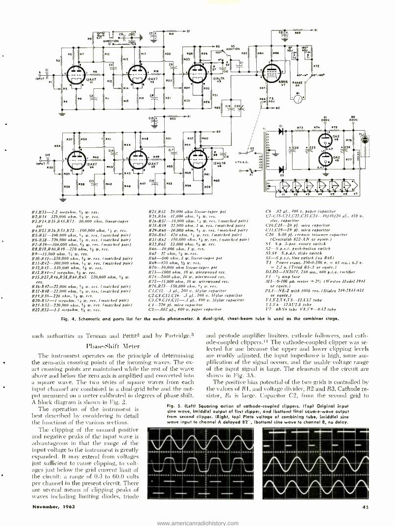
INPUT R
R
52 1
016EC710N71` 1//1
Sl . T6
C7 619 C21 669
620
92 9! A11017106
IRO*
o
10
121127 V2
12AU7A v5 66
V7
672
M -16 0 -166
RANGE S
R61
65 MI
62 66e ADJ
665 C19 C20
M 651
C17
X7 12A vs 60!
6 6
65
RI,R33 -2.2 megohm, 1i w. res. R2,R34 330,000 ohm, !z w. res. R3.R14,R3S.R45,R7I- -50,000 ohm. linear -taper
pot R4.R23,R36,R54,R72- 1110,000 ohm. I a m. res. RS- R37- IOO,000 ohm, r2 W. res. (matched pair) R64438- 220,000 ohm, 1= w. res. (matched pair) R7- R39- 100,000 ohm, 11 w. res. ( matched pair) RB.R18.R40,R49 -270 ohm. 1= w. res. R9- 1S,000 ohm, 17 w. res. R1O -R41 -- 330.000 ohm. 1= w. res. (snatched pair) RI1 -R42- 100,000 ohm, I2 W. res. (matched pair) R12.R43- 510.000 ohm, ! = w. res. R13,R44 -I ,negohm, 12 w. res. R1S,R27,R46,R58,R64,R65- 220.1)00 ohm, 11 w.
res. R16 -R47- 22,000 ohm. 12 w. res. (matched pair) R17- R48- 22,000 ohm. 1 = W. res. (matched pair) RI9,RS0 -220 ohm. 12 w. res. R20 -R51 -1 megohm. 1= w. res. ( matched pair) R21- R52- 2211,111111 ohm, I/2 w. res. (matched pair) R22.R53 -1.S megohm,
II7V.A.C.
R24.R55 20,000 ohm linear -taper pot R2S.RS6-- 47,000 ohm. I2 m. res. R26- R57- 10,1100 ohm, 12 w. res. ( matched pair) R28 -R59 22,00(0 ohm, / w. res. (matched pair) R29.R60- 10,000 ohm, i= w. res. (matched pair) R30 -R61 -470 ohm, 12 w. res. (matched pair) R31 -R62- 150.000 ohm, 12 W. res. (matched pair) R32,R63- 33,000 ohm. 1= w. res. R66- !0,000 ohm, 1 w. res. R67 --27 ohm, 1 í w. res. R68 -500 ohm, S w. linear -taper pot R69 -470 ohm. Ij= w. res. R70- 10,0(011 ohm linear -taper pot R73 -1000 ohm, 10 w. wirewound res. R74 -2000 ohm, 10 w. wirewound res. R75- 15.000 ohm, 10 w. wirewound res. R76,R77- 150,000 ohm, 12 w. res. C1,C12 -.I pi., 200 o. 3lylar capacitor C2,C8.CI3,C16 -.5 pl., 2(10 v..Uylar capacitor C3,C9,C14,C17 -.1 pf.. 400 v..1!ylar capacitor C4 220 pl. mica capacitor CS -.002 pf., 400 v. paper capacitor
Fig. 4. Schematic and parts list for the audio phasemeter. A dual -grid, sheet -beam
such authorities as Terman and Pettit'- and by Partridge.3
Phase -Shift Meter
The instrument operates on the principle of determining the zero-axis crossing points of the incoming waves. The ex- act crossing points are maintained while the rest of the wave above and below the zero axis is amplified and converted into a square wave. The two series of square waves from each input channel are combined in a dual -grid tube and the out- put measured on a meter calibrated in degrees of phase shift. A block diagram is shown in Fig. 2.
The operation of the instrument is best described by considering in detail the functions of the various sections.
The clipping of the unused positive and negative peaks of the input wave is advantageous in that the range of the input voltage to the instrument is greatly expanded. It may extend from voltages just sufficient to cause clipping, to volt- ages just below the grid current limit of the circuit; a range of 0.3 to 60.0 volts per channel in the present circuit. There are several means of clipping peaks of waves including limiting diodes, triode
November, 1963
71
52
295V 62
220V.
C6 -.02 p).. 41111 y. paper capacitor C7- C154.721,C22,C23,C24- 40/40/20 pf., 450 v.
elec. capacitor CIO,C18 -20 pl. mica capacitor CII.C19 -39 pl. mica capacitor C20- 8.50 pl. ceramic trimmer capacitor
(Centralab 822 -AN or equiv.) S/- S.p. 3 -pos. rotary switch SI- S.p.s.t. push -button switch S3.S4- S.p.d.t. slide switch S5- S.p.s.t. line switch (on 868) Tl Power trans. 300 -0.300 v. In 65 nta.; 6.3 v.
I,I 2.7 a. (Triad RS -A or equiv.) D1,D2- 1N2071, 730 ma., 600 p.i.v. rectifier Fl -1/2 amp fuse 311 -0.100 pa. meter 4-.2% (Weston Model 1941
or equiv.) PLI -NE -2 with 1011k res. I Dialco 249.7841.931
or equiv.) Vl,V2,V4,V5 -- 12..1'7 tube 1'3.1'6 -12ÁU7. tube 17 -613N6 tube 1'8.1'9 - -0.12 tube
tube is used as the combiner stage.
and pentode amplifier limiters, cathode followers, and cath- ode- coupled clippers." The cathode -coupled clipper was se- lected for use because the upper and lower clipping levels are readily adjusted, the input impedance is high, some am- plification of the signal occurs, and the usable voltage range of the input signal is large. The elements of the circuit are shown in Fig. 3A.
The positive bias potential of the two grids is controlled by the values of R1, and voltage divider, R2 and R3. Cathode re- sistor, Rv is large. Capacitor C2, from the second grid to
Fig. 5. (left) Squaring action of cathode- coupled clippers. (Top) Original input sine wave, (middle) output of first clipper, and (bottom) final square -wave output from second clipper. (Right, top) Plate voltage of combining tube, (middle) sine wove input to channel A delayed 82 , (bottom) sine wave to channel B, no delay.
at>>ELTAKINIIM 1111::1111:111:;111111 EMILMMEMEMBE
----
1:111111amoungli :i%i,i tilAI 11211112111P2110111011 111101111111MICAll1
45
www.americanradiohistory.com
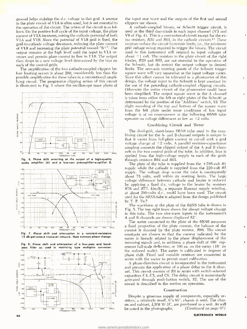
ground helps stabilize the d.c. voltage to this grid. A resistor in the plate circuit of VIA is often used, but is not essential to the operation of the circuit. The action of the circuit is as fol- lows. On the positive half cycle of the input voltage, the plate current of VIA increases, raising the cathode potential of both VIA and V1B. Since the potential of V1B grid is fixed, the grid -to- cathode voltage decreases, reducing the plate current of V1B and increasing the plate potential toward `B + ". The output remains at the high level until the input to VIA re- verses and permits plate current to flow in V1B. The output then drops to a new voltage level determined by the bias on each of the control grids.
The amplification of the two cathode -coupled clippers be- fore limiting occurs is about 200, considerably less than the possible amplification for these tubes in a conventional ampli- fying circuit. The progressive clipping action of this circuit is illustrated in Fig. 5 where the oscilloscope trace photo of
I 20
AUDIO NERAtOR
AMPI If !ER
o
PMASE METER
á 20 50 100 200 500 MC. 20C 'SEC
FREOUENCV -CPS
Fig. 6. Phase shift occurring at the output of a high -quality audio amplifier (Al and a low -cost preamplifier -amplifier B.
AMPLIFIER
AM .I ER 8
qEC 20EC SOKC 1000C.
.400
.0
.20
0
-20
-40
I
G .ASS
-S0
-100
-120 10 20
46
.......
P.S. PASS
4
- 20 Ì
-30
SO 100 200 500 IKC. NC SEC 0KC 20C 50KC CORE.
FREOUENCV -CPS
Fig. 7. Phase shift and attenuation in a constant -resistance 12 db -per- octave crossover network. Note extreme phase change.
Fig. 8. Phase shift and attenuation of a low -pass and band - pass filter as used in matrixing type multiplex converter.
-SO
the input sine wave and the outputs of the first and second clippers are shown.
A cathode- coupled binary, or Schmitt trigger circuit, is used as the third duo -triode in each input channel (V3 and V6 of Fig. 4) . This is a conventional circuit except for the ex- tra resistors, R30 and R61, in the cathode circuits.11 These resistors reduce the circuit hysteresis limits, i.e., the minimum grid voltage swing required to trigger the binary. The circuit used in this instrument will respond to input voltages of about ± 1 volt. The resistors in the plate circuit of the right triodes, R29 and R60, are not essential to the operation of the Schmitt, but do restrict the output voltage to desired limits. The zero -axis crossing points of the Schmitt trigger square wave will vary somewhat as the input voltage varies. Since this effect cannot be tolerated in a phasemeter of this design, the voltage input to the Schmitt is kept constant by the use of the preceding cathode -coupled clipping circuits. Otherwise the entire circuit of the phasemeter could have been simplified. The output square wave in the A channel is taken from either the left or right plates of the Schmitt as determined by the position of the "Addition" switch, S3. The slight rounding of the top and bottom of the square wave from the left plate under some conditions of low input voltage is of no consequence as the following 6BN6 tube operates on voltage differences as low as ± 2 volts.
Combining Circuit and Meter The dual -grid, sheet -beam 6BN6 tube used in the com-
bining circuit for the A- and B- channel outputs is unique in that it varies from full -plate current to cut -off with a grid voltage change of ±2 volts. A parallel resistive- capacitance coupling connects the clipped output of the A and B chan- nels to the two control grids of the tube. In addition, bias is applied from the high -voltage supply to each of the grids through resistors R64 and R65.
The plate of the tube is supplied from the +295 -volt B1 supply while the cathode is supplied from the 220 -volt B2 supply. The voltage drop across the tube is consequently about 75 volts, well within its working limits. The large voltage difference between cathode and heater is reduced by applying a fixed d.c. voltage to the heater by resistors R76 and R77. Ideally, a separate filament supply winding, at about 200 -volts d.c., could have been used. The circuit used for the 6BN6 tube is adapted from the design published by Y. P. Yu.9
The waveform at the plate of the 6BN6 tube is shown in Fig. 5. The top right trace shows the abrupt voltage change in this tube. The two sine -wave inputs to the instrument's A and B channels are shown displaced 82 °.
The meter connected to the plate of the 6BN6 measures a fixed proportion of the plate current; the balance of the cuiTent is shunted by the plate resistor, R66. The circuit constants are chosen so that the current indicated by the meter is linearly related to the phase displacement of the incoming signals and, in addition, a phase shift of 180° rep- resents full -scale deflection, or 100 µa. on the meter ( 18° on the reduced scale). The meter is calibrated in degrees of phase shift. Fixed and variable resistors are connected in series with the meter to permit exact calibration.
A phase -direction circuit is incorporated in the instrument and permits the application of a phase delay to the A chan- nel. This circuit consists of R9 in series with switch- selected capacitors C4, C5, and C6. The delay circuit is momentarily activated through push- button switch, S2. The use of the circuit is described in the section on operation.
Construction Despite a generous supply of components, especially re-
sistors, a relatively small, 6"x 831", chassis is used. The chas- sis and cabinet, LMB W -1C, are purchased as a unit. As will be noted in the photographs, (Continued on page 97)
ELECTRONICS WORLD
www.americanradiohistory.com
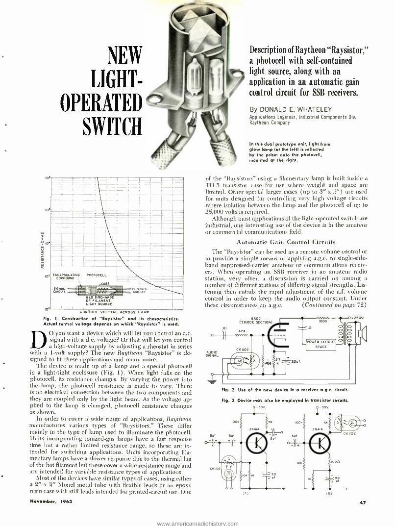
tos
tos
NEW
I
SWITCH
Description of Raytheon "Raysistor," ila photocell with self- contained light source, along with an
/ application in an automatic gain
control circuit for SSB receivers.
ENCAPSULATING PHOTOCELL COMPOUND
SIGNAL CIRCUIT
CASE
GAS DISCHARGE OR FILAMENT LIGHT SOURCE
CONTROL CIRCUIT
IOr CONTROL VOLTAGE ACROSS LAMP
Fig. 1. Construction of "Raysistor" and its characteristics. Actual control voltage depends on which "Raysistor" is used.
D O you want a device which will let you control an a.c. signal with a d.c. voltage? Or that will let you control a high -voltage supply by adjusting a rheostat in series
with a 1 -volt supply? The new Raytheon "Raysistor" is de- signed to fit these applications and many more.
The device is made up of a lamp and a special photocell in a light -tight enclosure ( Fig. 1) . When light falls on the photocell, its resistance changes. By varying the power into the lamp, the photocell resistance is made to vary. There is no electrical connection between the two components and they are coupled only by the light beam. As the voltage ap- plied to the lamp is changed, photocell resistance changes as shown.
In order to cover a wide range of applications, Raytheon manufactures various types of "Raysistors." These differ mainly in the type of lamp used to illuminate the photocell. Units incorporating ionized -gas lamps have a fast response time but a rather limited resistance range, so these are in- tended for switching applications. Units incorporating fila- mentary lamps have a slower response due to the thermal lag of the hot filament but these cover a wide resistance range and are intended for variable resistance types of applications.
Most of the devices have similar types of cases, using either a 2" x H" Mond metal tube with flexible leads or an epoxy resin case with stiff leads intended for printed -circuit use. One
November, 1963
By DONALD E. WHATELEY Applications Engineer, Industrial Components Div. Raytheon Company
In this dual prototype unit, light from glow lamp lat the left) is reflected by the prism onto the photocell, mounted at the right.
of the "Raysistors" using a filamentary lamp is built inside a TO -5 transistor case for use where weight and space are limited. Other special larger cases (up to 3" x ;2 ") are used for units designed for controlling very high voltage circuits where isolation between the lamp and the photocell of up to 25,000 volts is required.
Although most applications of the light- operated switch are industrial, one interesting use of the device is in the amateur or commercial communications field.
Automatic Gain Control Circuits
The "Raysistor" can be used as a remote volume control or to provide a simple means of applying a.g.c. to single -side- band suppressed -carrier amateur or communications receiv- ers. When operating an SSB receiver in an amateur radio station, very often a discussion is carried on among a number of different stations of differing signal strengths. Lis- tening then entails the rapid adjustment of the a.f. volume control in order to keep the audio output constant. Under these circumstances an a.g.c. (Continued on page 72)
.01
6507 ITRIODE SECTION)
+250V.
POWER OUTPUT
STAGE
Fig. 2. Use of the new device in a receiver a.g.c. circuit.
Fig. 3. Device may also be employed in transistor circuits. -30V. -30V.
IA) IB)
47
www.americanradiohistory.com
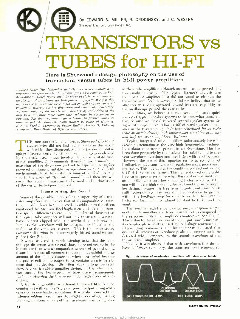
By EDWARD S. MILLER, R. GRODINSKY, and C. WESTRA
Sherwood Electronic Laboratories. Inc.
TRANSISTORS vs TUBES for HI -FI Here is Sherwood's design philosophy on the use of transistors versus tubes in hi -fi power amplifiers.
Editor's Note: Our .September and October issues contained an
important two -part article "Transistors for Hi -Fi: Panacea or Pan-
demonium?", which represented the views of H. H. Scott engineers on the use of transistors for hi -fi power amplifiers. We felt that mane of the points made were important enough and controversial enough to warrant further discussion and comments. Therefore, we sent copies of the article to a number of authorities in the
hi -fi field soliciting their comments- whether in agreement or opposed. Our first response is giren below. In further issues we
/tope to publish comments from Robert E. Furst of Harman - Kurdon, Fred L. Mergner of Fisher Radio. Morley D. Ka/ut of Acoustech, Dare Haller of Dynaco, and others.
THE transistor design engineers at Sherwood Electronic Laboratories did not find many points in the article with which they disagreed. Many of the design philos-
ophies discussed correlate with our own findings as evidenced by the design techniques involved in our solid -state inte- grated amplifier. Our comments, therefore, are primarily an extension of the discussion and relate especially to higher powered equipment suitable for operation in more difficult environments. First, let us discuss some of our findings rela- tive to the so- called "transistor sound," and then we will cover the types of transistors to be used and outline some of the design techniques involved.
Transistor- Amplifier Sound
Some of the possible reasons for the superiority of a tran- sistor amplifier's sound over that of a comparable vacuum - tube amplifier have been analyzed. In addition to the effects mentioned by Mr. von Recklinghausen and his co- authors, two special differences were noted. The first of these is that the typical tube amplifier will not only cause a sine wave to have its crest clipped when the overload point is reached, but also the waveform will be collapsed or kinked in the middle at the zero -axis crossing. (This is similar to severe crossover distortion in an improperly biased transistor am- plifier.) See Fig. 1.
It %vas discovered, through listening tests, that the kink- ing -type distortion was several times more noticeable to the human ear than was a comparable amount of peak -clipping distortion. Almost all common tube amplifiers exhibit a large amount of the kinking distortion %when overloaded because the grid circuit of the output tubes contains a resistive ele- ment that may develop a distorting bias due to grid- current flow. A good transistor amplifier design, on the other hand, can supply the low -impedance base drive requirements without disturbing the bias even under high overload con- ditions.
A transistor amplifier was found to sound like its tube counterpart %with up to 75q. greater power output rating when operated in overloaded conditions. It was also observed that listeners seldom were aware that slight overloading, causing clipping and some kinking of the waveforms, was taking place
48
in their tube amplifiers although an oscilloscope proved that this condition existed. The typical listener's analysis was that the tube amplifier `just did not sound as clear as the transistor amplifier "; however, he did not believe that either amplifier was being operated beyond its rated capability as the oscilloscope proved the case to be.
In addition, we believe Mr. von Recklinghausen's quick survey of typical speaker systems to be somewhat conserva- tive, because we have discovered several speaker- system de- signs with impedances as low as 40% of rated speaker imped- ance in the tweeter range. (We have scheduled for an early issue an article dealing with loudspeaker matching problems and hi-fi transistor amplifiers.- Editors)
Typical integrated tube amplifiers unfortunately have in- creasing attenuation at the very high frequencies, produced by a shunt capacitor to ground in a driver stage. This has been done purposely by the designer for stability and to pre- vent waveform overshoot and oscillation with reactive loads. However, the use of this capacitor results in reduction of feedback voltage causing loss of regulation and a poor damp- ing factor. This aggravates the condition pointed out in Fig. 6 (Part 1, September issue). This figure showed quite a dif- ference in speaker response when the speaker was used with an amplifier with very low damping factor as compared to one with a very high damping factor. Good transistor ampli- fier design, because it is free from output -transformer phase shift, generally requires less shunt capacitance to ground within the feedback loop for stability so that the damping factor can be maintained almost constant to 15 kc. and be- yond.
The resultant high -frequency square -wave response is gen- erally much smoother and freer of overshoot as compared to the response of its tube amplifier counterpart. See Fig. 2. This is due to the elimination of the output transformer with its complex phase shifts caused by its leakage reactance and interwinding resonances. Our listening tests indicated that even small amounts of overshoot peaks and ringing could be detected when compared to the smooth waveform of the transistorized amplifier.
Finally, it was observed that %vith waveforms that do not have half-wave symmetry, the transistor low -frequency re-
Fig. 1. Response of overloaded amplifiers with sine -wave inputs.
CLIPPING KINKING DISTORTION DISTORTION
ELECTRONICS WORLD
www.americanradiohistory.com
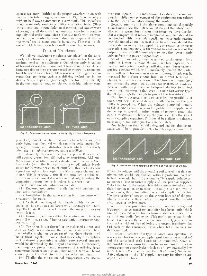
sponse was more faithful to the proper waveform than with comparable tube designs, as shown in Fig. 3. A waveform without half -wave symmetry is a saw- tooth. This waveform is not commonly used in amplifier evaluation tests. (Sine - wave distortion, intermodulation distortion, and square -wave checking are all done with symmetrical waveforms contain- ing only odd -order harmonics.) The saw -tooth with its even - as well as odd -order harmonic structure is quite similar to the waveform of many sounds in nature. This can be ob- served with human speech as well as wind instruments.
Types of Transistors We believe inadequate emphasis was placed on the supe-
riority of silicon over germanium transistors for low- and medium -level audio applications. One of the early bugaboos of transistors was the failure and deterioration of circuit per- formance due to base -current variations caused by rising am- bient temperatures. This problem was severe with germanium types thus requiring various stabilizing techniques in the design. Silicon types are gratifyingly free from this difficulty in the temperature range anticipated with high -fidelity com-
Fig. 2. Square -wave response at fairly high 15 -kc.l frequency.
ponent equipment. We find that some silicon types are pres- ently being manufactured which can offer noise figures, fre- quency response, and distortion levels which are entirely adequate for high -performance audio amplifiers.
Unfortunately, this is not true for the power stages which still require germanium diffused -alloy transistors. Although the technique of using finned, extruded, and black -anodized heat sinks ( with the fins vertically oriented) might barely suffice for 30- watts- per -channel amplifiers, this does not allow a great enough safety margin for a 50- watts- per -channel am- plifier. This is especially true if the amplifier is subjected to extreme environmental conditions that might destroy the germanium output device junctions in a short time.
These environmental situations include: (1) Enclosed -area custom installations with confined air -
circulation possibilities. (2) Installation in the same custom -built enclosure with
a vacuum -tube tuner. (3) Vertical mounting of the chassis ( with the control
knobs up) in a custom installation which destroys the "chim- ney- effect" air flow needed to cool the output transistor heat -sink fins.
(4) Unusual operation calling for continuous duty at or near full output, as would be the case with a continuous -tone test recording.
(5) Operation into a shorted or near -shorted output load such as might occur during the original installation. Here, the installer might not be aware of this short circuit until he has turned up the volume control to see why the amplifier isn't performing properly; in which case, several amperes would be delivered by the output transistors. Furthermore, the designer's precautionary measures of specifying large separating barriers on the amplifier output terminal board cannot prevent a short circuit at the speaker terminals.
(6) Finally, the environmental temperature can rise to
November, 1963
over 100 degrees F in some communities during the summer months, while poor placement of the equipment can subject it to the heat of radiators during the winter.
Because any or all of the above conditions could quickly (sometimes in less than 20 seconds) exceed the safety factor allowed for germanium output transistors, we have decided that a compact, dual 50 -watt integrated amplifier should be constructed with forced -air ventilation, constantly passing over the finned aluminum heat sink. In addition, should the forced -air fan motor be stopped for any reason or prove to be cooling inadequately, a thermostat located on one of the output transistors will immediately remove the power- supply voltage from the power -output stages.
Should a momentary short be applied to the output for a period of 1 msec. or more, the amplifier has a special feed- back circuit (patent pending) utilizing a non -linear current - sensing element which will immediately remove the audio - drive voltage. This non -linear current- sensing circuit can be bypassed by a short circuit from an output terminal to chassis, but, in this case, a small 3AC fuse would open here and protect the output transistors against damage. (Our ex- perience with using fuses as fool -proof devices to protect the output transistors is that even the new fast- acting types do not open rapidly enough to protect the transistors.)
The circuit designer must also consider the possibility of the output being shorted during installation before the am- plifier is turned on. \ \'hen the voltage is applied initially in this shorted condition, a well -regulated "B" supply could deliver up to several hundred watts of power through the output transistors to charge tip the grounded (by the short) output coupling capacitor. This would be sufficient to destroy most output transistor junctions immediately.
One technique that would safeguard against this occur- ranee would be to provide a relay to delay application of full
Fig. 3. Saw -tooth wave response obtained at frequency of 30 cps.
B "- supply voltage until the operating coil sensed that the sup- ply voltage could rise further svithout problems. Another technique would be to use a double "B "- supply voltage ar- rangement (one negative supply and one positive supply). \Vith this circuit the output transistors are matched so that their junction point, from which the output is taken, will be at zero volts, thus eliminating the output coupling capacitor. We have preferred not to use this circuit because of the pos- sibility of a d.c. voltage being developed here that would affect speaker performance.
With all these protective features, a compact, integrated high -performance transistor amplifier has been built which can be operated with both channels delivering 55 watts r.m.s. at any audio frequency. This performance can be ob- tained even when the unit is confined in a typical custom installation without fear of losing the output transistors (at $12 each to the consumer) even when both channels are short -circuited.
In order to achieve this type of continuous operation, it is necessary for the power -supply regulation to be optimized and the series -load path losses to be minimized. Some of the possible series losses that can be encountered are in the output coupling electrolytics which must have unusually low series losses. (We specify less than 0.25 ohm.) Series re- sistive elements in the "B "- supply necessary for filtering are kept to below 3 ohms.
49
www.americanradiohistory.com
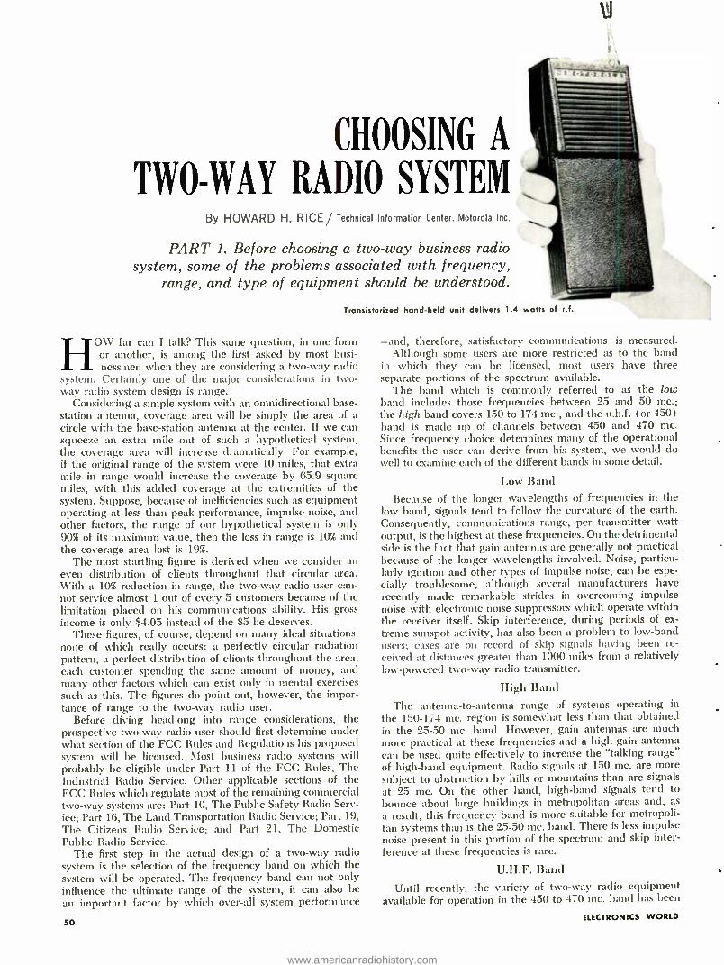
CHOOSING A
TWO-WAY RAI110 SYSTEM By HOWARD H. RICE/ Technical Information Center, Motorola Inc.
PART 1. Before choosing a two -way business radio system, some of the problems associated with frequency,
range, and type of equipment should be understood.
Transistorized hand -held unit delivers 1.4
I fO\V far can I talk? This same question, in one form
or another, is among the first asked by most busi- nessmen when they are considering a two -way radio
system. Certainly one of the major considerations in two - way radio system design is range.
Considering a simple system with an omnidirectional base - station antenna, coverage area will be simply the area of a circle with the base- station antenna at the center. If we can squeeze an extra mile out of such a hypothetical system, the coverage area will increase dramatically. For example, if the original range of the system were 10 miles, that extra mile in range would increase the coverage by 65.9 square miles, with this added coverage at the extremities of the system. Suppose, because of inefficiencies such as equipment operating at less than peak performance, impulse noise, and other factors, the range of our hypothetical system is only 90% of its maximum value, then the loss in range is 10% and the coverage area lost is 19 %.
The most startling figure is derived when we consider an even distribution of clients throughout that circular area. With a 10% reduction in range, the two -way radio user can- not service almost 1 out of every 5 customers because of the limitation placed on his communications ability. His gross income is only $4.05 instead of the $5 he deserves.
These figures, of course, depend on many ideal situations, none of which really occurs: a perfectly circular radiation pattern, a perfect distribution of clients throughout the area, each customer spending the same amount of money, and many other factors which can exist only in mental exercises such as this. The figures do point out, however, the impor- tance of range to the two -way radio user.
Before diving headlong into range considerations, the prospective two -way radio user should first determine under what section of the FCC Rules and Regulations his proposed system will be licensed. Most business radio systems will probably be eligible under Part 11 of the FCC Rules, The Industrial Radio Service. Other applicable sections of the FCC Rules which regulate most of the remaining commercial two -way systems are: Part 10, The Public Safety Radio Serv- ice; Part 16, The Land Transportation Radio Service; Part 19, The Citizens Radio Service; and Part 21, The Domestic Public Radio Service.
The first step in the actual design of a two -way radio system is the selection of the frequency band on which the system will be operated. The frequency band can not only influence the ultimate range of the system, it can also be an important factor by which over -all system performance
50
watts of ri.
-and, therefore, satisfactory communications -is measured. Although some users are more restricted as to the band
in which they can be licensed, most users have three separate portions of the spectrum available.
The band which is commonly referred to as the low band includes those frequencies between 25 and 50 mc.; the high band covers 150 to 174 mc.; and the u.h.f. (or 450) band is made up of channels between 450 and 470 mc. Since frequency choice determines many of the operational benefits the user can derive from his system, we would do well to examine each of the different bands in some detail.
Low Band
Because of the longer wavelengths of frequencies in the low band, signals tend to follow the curvature of the earth. Consequently, communications range, per transmitter watt output, is the highest at these frequencies. On the detrimental side is the fact that gain antennas are generally not practical because of the longer wavelengths involved. Noise, particu- larly ignition and other types of impulse noise, can be espe- cially troublesome, although several manufacturers have recently made remarkable strides in overcoming impulse noise with electronic noise suppressors which operate within the receiver itself. Skip interference, during periods of ex- treme sunspot activity, has also been a problem to low -band users; cases are on record of skip signals having been re- ceived at distances greater than 1000 miles from a relatively low -powered two -way radio transmitter.
High Band
The antenna -to- antenna range of systems operating in
the 150 -174 mc. region is somewhat less than that obtained in the 25 -50 mc. band. However, gain antennas are much more practical at these frequencies and a high -gain antenna can be used quite effectively to increase the "talking range" of high -band equipment. Radio signals at 150 mc. are more subject to obstruction by hills or mountains than are signals at 25 mc. On the other hand, high -band signals tend to bounce about large buildings in metropolitan areas and, as
a result, this frequency band is more suitable for metropoli- tan systems than is the 25 -50 mc. band. There is less impulse noise present in this portion of the spectrum and skip inter- ference at these frequencies is rare.
U.H.F. Band
Until recently, the variety of two -way radio equipment available for operation in the 450 to 470 mc. band has been
ELECTRONICS WORLD
www.americanradiohistory.com
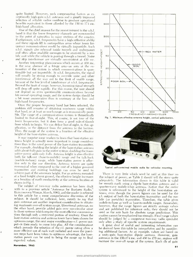
quite limited. However, such compensating factors as ex- ceptionally high -gain u.h.f. antennas and a greatly improved selection of reliable radios combine to produce operational benefits equivalent to those afforded by the 150 to 174 mc. high -band allocation.
One of the chief reasons for the recent interest in the u.h.f. band is that the lower frequency channels are overcrowded to the point of saturation in many sections of the country. Furthermore, n.h.f. frequencies have a high reflective ability and these signals fill in metropolitan areas where lower fre- quency communications would be virtually impossible. Such u.h.f. signals also rebound inside tunnels and underpasses and often allow readable messages to be received by a mo- bile unit while the vehicle is passing through a tunnel. Noise and skip interference are virtually non- existent at 450 me.
Another interesting phenomenon which occurs at 450 mc. is the near absence of a fringe area -an area at the ex- tremities of the system in which communications is ques- tionable but not impossible. At u.h.f. frequencies, the signal will usually be strong enough to override noise and other interference all the way out to the limit of usable range, because of the low level of interference at u.h.f. frequencies. Beyond the limit of range, however, incoming signal strength will drop off quite rapidly. For this reason, the user should not depend on even questionable communications beyond his normal operating range, and the system design should be a bit inure conservative than is necessary at the low- and high -band frequencies.
Once the proper frequency band has been selected, the problem still remains of obtaining maximum range within that band, or at least as much range as is economically possi- ble. The range of a communications system is theoretically limited to line -of- sight. This, of course, is not true of the lower frequencies, but it does form a good rule -of -thumb from which to begin. We can define line -of- sight, in this ap- plication, as the distance from the antenna to the horizon. Thus, the range of the system is a function of the effective height of the base -station antenna.
It may surprise some readers to learn that base -station an- tenna height is actually more important in range considera- tions than is the rated power of the base- station transmitter. For example, doubling the height of the base -station antenna adds about 6 -db gain to the entire system; doubling the trans- mitter per adds only 3 db. Antenna height is also effective both for talk -out (base -to- mobile) range and for talk -back (mobile -to -base) range, while base- station power is effec- tive only in the one direction. Antenna towers are quite economical when compared to the cost of a higher powered transmitter and existing buildings can even be used to achieve part of the necessary height. For an antenna mounted at a fixed height above ground, the effective height increases as a function of earth conductivity at the antenna location as shown in Fig. 1.
The subject of two -way radio antennas has been dealt with in a previous article "Antennas for Business Radio," ELECTRONICS \Voal.r, March, 1963, and the reader is referred to this article for a more comprehensive discussion of the subject. It should be sufficient, here, merely to say that gain antennas are another important consideration in obtain- ing maximum over -all system range. Directional antennas, on the other hand, provide added gain over non -circular areas in those systems which require the most efficient communica- tions through only a restricted portion of territory. Once the base -station antenna and antenna tower have been chosen for optimum range, the next major consideration -r.f. power out - put-is then ready to come into play. All the considerations which precede the selection of the r.f. power rating allow a more efficient use of each watt radiated and once the previ- ous steps have been taken to optimum advantage, the base - station power can be used to bring the range up to final expected values.
November, 1963
1000
Soo
200
w
10 20 50 100 200 500 FREQUENCY- MEGACYCLES
Fig. 1. Minimum effective antenna height, vertical polarization.
'000
Typical self -contained mobile radio for vehicular mounting.
There is very little which need be said at this time on the subject of power, as Table 1 should tell the story quite adequately. The information shown in this table is valid for smooth earth using a dipole base -station antenna and a quarter -wave mobile -whip antenna. Notice that the entire system is referenced to the height of the base -station an- tenna, even though the power figures can be used for the r.f. output of both the base -station transmitter and the mo- bile (or portable) transmitter. Therefore, the table gives mobile -to -base as well as base -to- mobile ranges. Remember, however, that the range figures are strictly average values and are published for reference only; they should not be used as the sole basis for absolute range predictions. This caution cannot be emphasized too strongly. Final range values should be judged by a competent two -way radio specialist only after a study of specific system requirements.
A great deal of useful and interesting information can be derived from this table by interpolation and by consider- ing additional factors. As an example, values are based on a . unity -gain base- station dipole antenna. However, gain antennas in the 150 -174 mc. and 450 to 470 mc. regions will increase the over -all range of the system. Each db of gain
S1
www.americanradiohistory.com
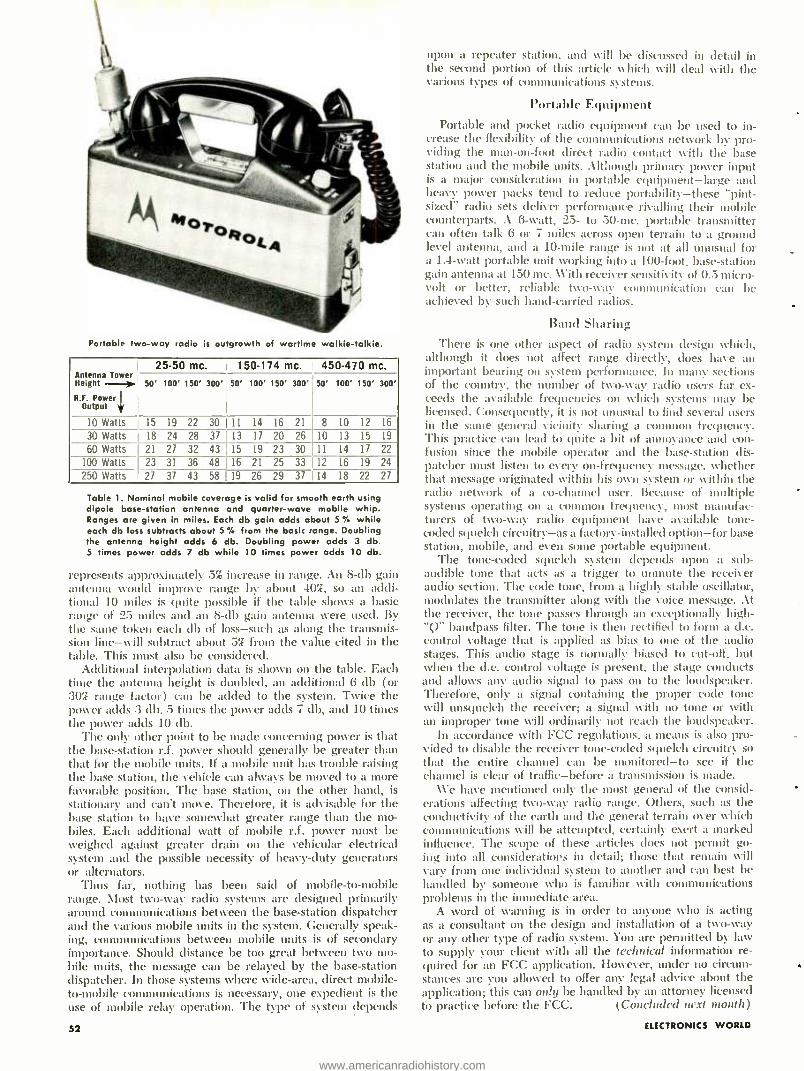
Portable two -way radio is outgrowth of wartime walkie -talkie.
Antenna Tower Heigit
25 -50 mc. i 150 -174 mc. 450 -470 mc.
50' 100' 150' 300' 50' 100' 150' 300' 50' 100' 150' 300' ---). R.F. Power
Output
10 Watts 15 19 22 30 11 14 16 21 8 10 12 16
30 Watts 18 24 28 37 13 17 20 26 10 13 15 19
60 Watts 21 27 32 43 15 19 23 30 11 14 17 22
100 Watts 23 31 36 48 16 21 25 33 12 16 19 24 250 Watts 27 37 43 58 19 26 29 37 114 18 22 27
Table 1. Nominal mobile coverage is valid for smooth earth using dipole base -station antenna and quarter -wave mobile whip. Ranges are given in miles. Each db gain adds about 5 °í, while each db loss subtracts about 5 °, from the basic range. Doubling the antenna height adds 6 db. Doubling power adds 3 db. 5 times power adds 7 db while 10 times power adds 10 db.
represents approxiulatt l .5 increase in range. An 8 -db gain antenna would impro\ e range by about 402, so an addi- tional 10 miles is quite possible if the table shows a basic range of 25 miles and an 8 -db gain antenna were used. By the same token each db of loss -such as along the transmis- sion line -will subtract about 5% from the value cited in the table. This must also be considered.
Additional interpolation data is shown on the table. Each time the antenna height is doubled, an additional 6 db (or 30 %% range factor) can be added to the system. Twice the power adds :3 db. 5 times the power adds 7 db, and 10 times the power adds 10 db.
The only other point to be made concerning power is that the base- station r.f. power should generally be greater than that for the mobile units. If a mobile unit has trouble raising the base station, the vehicle can always be moved to a more favorable position. The base station, on the other hand, is stationary and can't move. Therefore, it is advisable for the base station to have somewhat greater range than the mo- biles. Each additional watt of mobile r.f. power must be weighed against greater drain on the vehicular electrical system and the possible necessity of heavy -duty generators or alternators.
Thus far, nothing has been said of mobile -to- mobile range. Most two -way radio systems are designed primarily around communications between the base- station dispatcher and the various mobile units in the system. Generally speak- ing, communications between mobile units is of secondary importance. Should distance be too great between two mo- bile units, the message can be relayed by the base -station dispatcher. In those systems where wide -area, direct mobile - to- mobile communications is necessary, one expedient is the use of mobile relay operation. The type of system depends
52
upon a repeater station, and will be discussed in detail in the second portion of this article which will deal with the various types of communications systems.
Portable Equipment Portable and pocket radio equipment can be used to in-
crease the flexibility of the communications network by pro- viding the man -on -foot direct radio contact with the base station and the mobile units. Although primary power input is a major consideration in portable equipment -large and heavy power packs tend to reduce portability -these "pint - sized" radio sets deliver performance rivalling their mobile counterparts. A 6 -watt, 25- to 50 -mc. portable transmitter can often talk 6 or 7 miles across open terrain to a ground level antenna, and a 10 -mile range is not at all unusual for a 1.4 -watt portable unit working into a 100 -foot, base- station gain antenna at 150 mc. With receiver sensitivity of 0.5 micro- volt or better, reliable two -way communication can be achieved by such hand -carried radios.
Band Sharing There is one other aspect of radio system design which,
although it does not affect range directly, does have an important bearing on system performance. In many sections of the country, the number of two -way radio users far ex- ceeds the available frequencies on which systems may be licensed. Consequently, it is not unusual to find several users in the sane general vicinity sharing a common frequency. This practice can lead to quite a bit of annoyance and con- fusion since the mobile operator and the base- station dis- patcher must listen to every on- frequency message, whether that message originated within his own system or within the radio network of a co- channel user. Because of multiple systems operating on a common frequency, most manufac- turers of two -way radio equipment have available tone - coded squelch circuitry -as a factory -installed option -for base station, mobile, and even some portable equipment.
The tone -coded squelch system depends upon a sub - audible tone that acts as a trigger to unmute the receiver audio section. The code tone, from a highly stable oscillator, modulates the transmitter along with the voice message. At the receiver, the tone passes through an exceptionally high - 'Q" bandpass filter. The tone is then rectified to form a d.c. control voltage that is applied as bias to one of the audio stages. This audio stage is normally biased to cut -off. but when the d.c. control voltage is present, the stage conducts and allows any audio signal to pass on to the loudspeaker. Therefore, only a signal containing the proper code tone will unsquelch the receiver; a signal with no tone or with an improper tone will ordinarily not reach the loudspeaker.
In accordance with FCC regulations, a means is also pro- vided to disable the receiver tone -coded squelch circuitry so that the entire channel can be monitored -to see if the channel is clear of traffic -before a transmission is made.
We have mentioned only the most general of the consid- erations affecting two -way radio range. Others, such as the conductivity of the earth and the general terrain over which communications will be attempted, certainly exert a marked influence. The scope of these articles does not permit go- ing into all considerations in detail; those that remain will vary from one individual system to another and can best be handled by someone who is familiar with communications problems in the immediate area.
A word of warning is in order to anyone who is acting as a consultant on the design and installation of a two -way or any other type of radio system. You are permitted by law to supply your client with all the technical information re- quired for an FCC application. However, under no circum- stances are you allowed to offer any legal advice about the application; this can only be handled by an attorney licensed to practice before the FCC. (Concluded next month)
ELECTRONICS WORLD
www.americanradiohistory.com
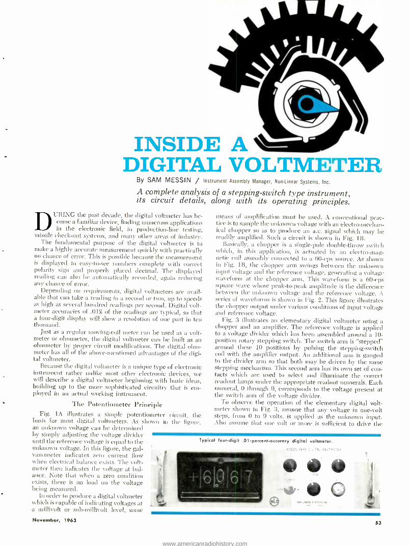
INSIDE A DIGITAL VOLTMETER
By SAM M ES I N / Instrument Assembly Manager, Non -Linear Systems, Inc.
A complete analysis of a stepping- switch type instrument, its circuit details, along with its operating principles.
DUFtING the past decade, the digital voltmeter has be- come a familiar device, finding numerous applications in the electronic field, in production -line testing,
missile check -out systems, and many other areas of industry. The fundamental purpose of the digital voltmeter is to
make a highly accurate measurement quickly with practically no chance of error. This is possible because the measurement is displayed in easy -to -see numbers complete with correct polarity sign and properly placed decimal. The displayed reading can also be automatically recorded, again reducing any chance of error.
Depending on requirements, digital voltmeters are avail- able that can take a reading in a second or two, up to speeds as high as several hundred readings per second. Digital volt- meter accuracies of .01¶ of the readings are typical, so that a four -digit display will show a resolution of one part in ten thousand.
Just as a regular moving-coil meter can be used as a volt- meter or ohmmeter, the digital voltmeter can be built as an ohmmeter by proper circuit modifications. The digital ohm- meter has all of the above -mentioned advantages of the digi- tal voltmeter.
Because the digital voltmeter is a unique type of electronic instrument rather unlike most other electronic devices, we will describe a digital voltmeter beginning with basic ideas, building up to the more sophisticated circuitry that is em- ployed in an actual xvorking instrument.
The Potentiometer Principle Fig. IA illustrates a simple potentiometer circuit, the
basis for most digital voltmeters. As shown in the figure. an unknown voltage can be determined by simply adjusting the voltage divider until the reference voltage is equal to the unknown voltage. In this figure, the gal- vanometer indicates zero current flow when electrical balance exists. The volt - meter then indicates the voltage at bal- ance. Note that when a zero condition exists, there is no load on the voltage being measured.
In order to produce a digital voltmeter which is capable of indicating voltages at a millivolt or sub -millivolt level, some
means of amplification must be used. A conventional prac- tice is to sample the unknown voltage with an electro- mechan- ical chopper so as to produce an a.c. signal which may be readily amplified. Such a circuit is shown in Fig. 1B.
Basically, a chopper is a single -pole double -throw switch which, in this application, is actuated by an electromag- netic coil assembly connected to a 60 -cps source. As shown in Fig. 1B, the chopper arm swings between the unknown input voltage and the reference voltage, generating a voltage waveform at the chopper arm. This waveform is. a 60 -cps square wave whose peak -to -peak amplitude is the difference between the unknown voltage and the reference voltage. A series of waveforms is shown in Fig. 2. This figure illustrates the chopper output under various conditions of input voltage and reference voltage.
Fig. 3 illustrates an elementary digital voltmeter using a chopper and an amplifier. The reference voltage is applied to a voltage divider which has been assembled around a 10- position rotary stepping switch. The switch arm is "stepped" around these 10 positions by pulsing the stepping- switch coil with the amplifier output. An additional arm is ganged to the divider arm so that both may be driven by the same stepping mechanism. This second arm has its own set of con- tacts which are used to select and illuminate the correct readout lamps under the appropriate readout numerals. Each numeral, 0 through 9, corresponds to the voltage present at the switch arm of the voltage divider.
To observe the operation of the elementary digital volt- meter shown in Fig. 3, assume that any voltage in one -volt steps, from 0 to 9 volts, is applied as the unknown input. Also assume that one volt or more is sufficient to drive the
Typical four -digit .01- percent -accuracy digital voltmeter.
,6 - ,'+, rJ;',..ETEP
e_ r c 60 :AIM sucn.:K.
A
November, 1963 53
www.americanradiohistory.com

GALVANOMETER j.
+ r
3 Y J
VOLTMETER
_p l (A)
+ - KNOWN REF VOLT.
1
-a TO AMPLIFIER
!B)
Fig. 1. (A) Potenl:ometer circuit. (B) Use of a chopper.
ó
+
o
ó
ti
REF. REF.
REF. REF.
IN. IN.
IN.
TIME
IN.
=E
iN
Fig. 2. Chopper output for two cases of positive input volt- age and two cases of negative input voltage. Square -wave pol- arity depends on whether input is greater or less than reference.
i
Inside view of the voltmeter discussed. One of the four stepping- switch panels has been unplugged in this photo.
amplifier which, in turn, drives the stepping switch. When these conditions occur, the following facts become evident:
1. With any input from 0 to 9 volts, only one particular position on the reference voltage divider will match the input voifag.e.
°_. All other positions will produce a voltage output of one volt or more at the chopper arm. This is sufficient to drive the amplifier and the stepping switch.
3. The stepping switch will receive one pulse for each full swing of the chopper arm as long as a difference exists be- tween the unknown input voltage and the reference voltage.
4. When the reference voltage- divider output equals the unknown input voltage, no output is developed at the chopper arm, and the amplifier ceases to operate the stepping switch.
5. The second section of the stepping switch connects to a specific readout lamp when balance is reached. An appro- priate numeral is illuminated, which corresponds to the ref-
54
erence voltage divider tap and therefore corresponds to the amount of unknown voltage applied.
A Practical DVM
Although the simplified circuit of Fig. 3 illustrates the principle upon which a digital voltmeter works, consider- ably more sophisticated circuitry is required to produce a practical instrument. The following discussion, based on the specific circuit used in the NLS Model V64A, illustrates some of the details. This instrument does not have automatic range switching or automatic polarity indicating features. Instead, it uses front -panel controls to establish range and polarity.
First of all, the elementary circuit shown in Fig. 3 can- not measure an input voltage of reverse polarity unless the reference voltage is also reversed. Second, like all volt- meters, the digital voltmeter requires a range multiplier to extend its useful range. Third, the chopper must be protected against the inadvertent application of excess voltage.
Fig. 4 shows the circuit changes made to meet these re- quirements. A polarity- reversing switch has been added to reverse the reference voltage; an input voltage divider and range switch have been added to extend the voltage ranges by ten times and a hundred times; also, a neon lamp and limiting resistor have been added to protect the chopper against accidental high -voltage inputs.
Any practical digital voltmeter must contain an extremely stable voltage source for reference purposes if the instru- ment is to be consistently accurate over long periods of time. Fig. 5 shows a typical reference supply used in digital volt- meters.
To obtain the precise increments in voltage required of a digital voltmeter, a modified Kelvin -Varley type voltage divider is used. With this modified divider, the value of each decade resistor is the same, thus permitting each dec- ade, along with its stepping switch, to be made into inter- changeable plug -in units. Since all decades are interchange- able, production, troubleshooting, and replacement are simple.
As shown in Fig. 6, each decade consists of eleven 5000 - ohm resistors. The decade output is selected by a pair of switch arms across two adjacent resistors. The last decade output is shunted by a 12,500 -ohm resistor and a 50.000 -ohm terminating resistor. A quick calculation will show that the 10,000 -ohm output shunted by the 12,500 -ohm resistor and the 50.000 -ohm terminating resistor, equals 5000 ohms. Therefore, total decade resistance is 50,000 ohms, and 1 /10th the decade voltage appears across the output. Each dec- ade is similarly divided and terminated by the next decade.
CHOPPER
UNKNOWN VOLTAGE
eO,*
Fig. 3. Elementary digital voltmeter. As the stepping switch rotates indicating lights illuminate numbers corresponding to voltage.
:V ts,
STEPPING SWITCH
REFERENCE VOLTAGE
9V.
4
SV.
ELECTRONICS WORLD
www.americanradiohistory.com
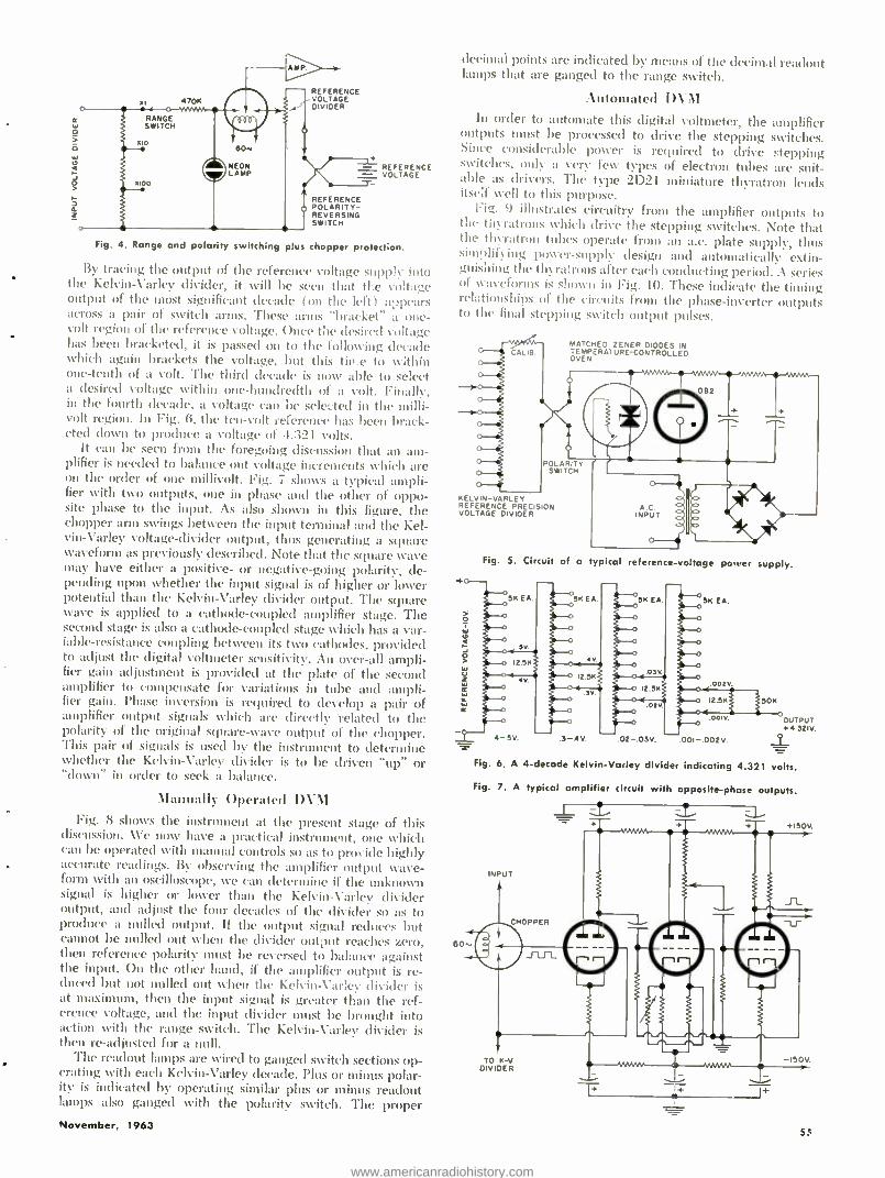
470K
RANGE SWITCH
---I AMP
REFERENCE VOLTAGE DIVIDER
60-
NEON LAMP
REFERENCE POLARITY - REVERSING SWITCH
REFERENCE VOLTAGE
Fig. 4. Range and polarity switching plus chopper protection.
By tracing the output of the reference voltage supply into the Kelvin -Varley divider, it will be seen that tige voltage output of the most significant decade (on the left) appears across a pair of switch arms. These arms "bracket" a one - volt region of the reference voltage. Once the desired voltage has been bracketed, it is passed on to the following decade which again brackets the voltage, but this tirre to within one -tenth of a volt. The third decade is now able to select a desired voltage Nvithin one -hundredth of a volt. Finally, in the fourth decade, a voltage can be selected in the milli- volt region. In Fig. 6, the ten -volt reference has been brack- eted down to produce a voltage of 4.321 volts.
It can be seen from the foregoing discussion that an am- plifier is needed to balance out voltage increments which are on the order of one millivolt. Fig. 7 shows a typical ampli- fier with two outputs, one in phase and the other of oppo- site phase to the input. As also shown in this figure, the chopper arm swings between the input terminal and the Kel- vin-Varley voltage -divider output, thus generating a square waveform as previously described. Note that the square wave may have either a positive- or negative -going polarity, de- pending upon whether the input signal is of higher or lower potential than the Kelvin -Varley divider output. The square wave is applied to a cathode- coupled amplifier stage. The second stage is also a cathode -coupled stage which has a var- iable- resistance coupling between its two cathodes, provided to adjust the digital voltmeter sensitivity. An over -all ampli- fier gain adjustment is provided at the plate of the second amplifier to compensate for variations in tube and ampli- fier gain. Phase inversion is required to develop a pair of amplifier output signals which are directly related to the polarity of the original square -wave output of the chopper. This pair of signals is used by the instrument to determine whether the Kelvin -Varley divider is to be driven "up" or "down" in order to seek a balance.
Manually Operated DVM Fig. 8 shows the instrument at the present stage of this
discussion. We now have a practical instrument, one which can be operated with manual controls so as to provide highly accurate readings. By observing the amplifier output wave- form with an oscilloscope, we can determine if the unknown signal is higher or lower than the Kelvin -Varley divider output, and adjust the four decades of the divider so as to produce a nulled output. If the output signal reduces but cannot be nulled out %hen the divider output reaches zero, then reference polarity must be reversed to balance against the input. On the other hand. if the amplifier output is re- duced but not nulled out when the Kelvin -Varley divider is at maximum, then the input signal is greater than the ref- erence voltage, and the input divider must be brought into action with the range switch. The Kelvin -Varley divider is then re- adjusted for a null.
The readout lamps are wired to ganged switch sections op- erating with each Kelvin- Varley decade. Plus or minus polar- ity is indicated by operating similar phis or minus readout lamps also ganged with the polarity switch. The proper November, 1963
decimal points are indicated by means of the decimal readout lamps that are ganged to the range switch.
Automated DVM In order to automate this digital voltmeter, the amplifier
outputs must be processed to drive the stepping switches. Since considerable power is required to drive stepping switches, only a very few types of electron tubes are suit- able as drivers. The type 2D21 miniature thyratron lends itself well to this purpose.
Fig. 9 illustrates circuitry from the amplifier outputs to the thyratrons which drive the stepping switches. Note that the thyratron tubes operate from an a.c. plate supply, thus simplifying power- supply design and automatically extin- guishing the thyratrons after each conducting period. A series of waveforms is shown in Fig. 10. These indicate the timing relationships of the circuits from the phase -inverter outputs to the final stepping switch output pulses.
MATCHED ZENER DIODES IN TEMPERATURE-CONTROLLED OVEN
082
POLARITY SWITCH
KELVIN- VARLEY REFERENCE PRECISION VOLTAGE DIVIDER
Fig. 5. Circuit of a ypical reference -voltage power supply.
02 -.03V. 001- 002 v
OUTPUT +4 ó21V.
Fig. 6. A 4- decade Kelvin - Varley divider indicating 4.321 volts.
Fig. 7. A typical amplifier circuit with opposite -phase outputs.
INPU T
4.15C);
TO K -V DIVIDER
M _1+
55
www.americanradiohistory.com
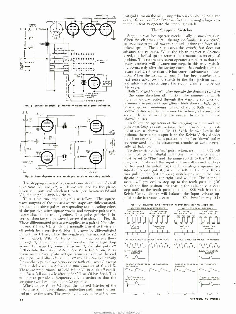
RANGE AT TEN.
CHOPPER
1000Y
H
0000000000 0 00000000 0 00000000 0 00000000 0 I 2 J 4 5 6 7 S 9
READOUT LAMPS
Fig. 8
k' + TO POLARITV- ,,,,____, INDICATING
LAMPS
L- TO POWER SUPPLY
Simplified circuit of manually operated digital voltmeter.
Fig. 9. Four thyratrons are employed to drive stepping switch.
The stepping switch drive circuit consists of a pair of small thyratrons, V1 and V2, which are actuated by the phase - inverter outputs, and which in turn trigger thyratrons 173 and V4, the stepping -switch drivers.
These thyratron circuits operate as follows: The square - wave outputs of the phase -inverter stage are differentiated, producing positive pulses corresponding to the leading edges of the positive -going square waves, and negative pulses cor- responding to the trailing edges. This pulse polarity is in- verted when the square wave is inverted as shown in Fig. 10. These differentiated pulses are applied to a pair of 5696 thy- ratrons, VI and V2, which are normally biased to their cut- off points by a resistive divider. The positive differentiated pulse turns V1 on, while the negative pulse applied to V2 has no effect. With V1 turned on, a large current flows through R, the common cathode resistor. The voltage drop across R charges C, connected across R, and also puts V2 further into the cut-off state. Once V1 is turned on, it re- mains on until a.c. plate voltage returns to zero at the end of the positive half -cycle. V1 and V2 would normally be ready for another cycle of operation every 60th of a second except for the delay resulting from the time constant of C and R. These are proportioned to hold V2 or V1 in a cut -off condi- tion for a full a.c. cycle after either V1 or V2 has fired. This is done to provide a frequency- halving action so that the stepping switches operate at it 30 -cps rate.
When either V1 or V2 fires, the ionized interior of the tube creates a low -impedance conducting path from the con- trol grid to the plate. The resulting voltage pulse at the con-
56
trol grid turns on the neon lamp which is coupled to the 2D21 output thyratron. The 2D21 switches on, passing a large cur- rent sufficient to operate the stepping switch.
The Stepping Switches Stepping switches operate mechanically in one direction.
\ \'hen the electromagnetic driving mechanism is energized, an armature is pulled toward the coil against the force of a helical spring. The action cocks the switch, but does not advance the contacts. \\'hen the electromagnet is de -ener- gized, the helical spring returns the armature to its original position. This return movement operates a ratchet so that the rotary contacts will advance one step. In this way, switch- ing occurs only after the driving current has ended; thus the return spring rather than driving current advances the con- tacts. \Vhen the last switch position has been reached, the next pulse advances the switch to the first position again, and additional pulses cause the stepping switch to repeat this cycle.
Both "up" and "down" pulses operate the stepping switches in the same direction of rotation. The manner in which these pulses are routed through the stepping switches de- termines a sequence of operation which allows a balance to be reached in a minimum number of steps. Both "up" and "down" pulses are usually required to achieve a balance. and several decks of switches are needed to route "up" and "down" pulses.
To follow the operation of the stepping switches and the pulse -switching circuits, assume that all switches are rest- ing at zero as shown in Fig. 11. With the switches in this position, there is no output from the Kelvin -Varlev divider and, if no input voltage is present, no "up" or "down" pulses are generated and the instrument remains at zero, electri- cally at balance.
To demonstrate the "up" -pulse action, assume -'- .009 volt is applied to the digital voltmeter. The polarity switch must be set to "Plus" and the range switch to the "10-Volt" range. Application of this input voltage will cause the chop- per to detect the unbalance, thereby creating a square -wave signal of proper polarity, .which results in the "up" thyra- tron pulsing the first stepping switch- producing the least significant number in the right -hand window. This stepping switch will proceed to step up to the tenth position ( "0" equals the first position ) decreasing the unbalance at each step until at the tenth position, the +.009 volt from the Kelvin- Varlev divider will balance the input voltage ap- plied to the instrument, cans- (Continued on page 84)
Fig. 10. Inverter and thyratron INPUT GREATER THAN REFERENCE
"UP" PHASE- DOWN' PHASE - INVERTER OU -PUT INVERTER OUTPUT
M N IN IN REF REF REF REF
IN IM N REF REF REY REF
"UP" DUFF. OUTPUT LIIIIIIil
A.C. PLATE VOLTAGE
'VUV1J "UP" THYRATRON
CURRENT rL-lL
waveforms during stepping. INPUT LESS THAN REFERENCE
"UP" PHASE- 'DOWN" PHASE - INVERTER OUTPUT INVERTER OUTPUT
REF REF REF REF. w IN IM IN
U LJ L_ U I U J__ W NI IM M REF REF REF. REF.
"DOWN-DIFF "UP" DUFF "DOWN" DIFF. OUTPUT OUTPUT OUTPUT
I I I I I I I I I I I I l I I I 1 I I l I I I I l I
ON ALL THYRATRONS
CHARGE ACROSS RC (VI ,V2 THYRATRON CATHODES)
"UP" STEPPING SWITCH DRIVE PULSE
ME
.C. PLATE VOLTAGE ON ALL THYRATRONS
.'DOWN" THYRATRON CURRENT
CHARGE ACROSS RC IVI ,V2 THYRATRON CATHODES)
"DOWN" STEPPING SWITCH DRIVE PULSE
TIME T M'
ELECTRONiCS WORLD
www.americanradiohistory.com
who's m ding your
store:this season?
m i n 11
CHANNEL MASTER ...Irom Fall through Christmas!
We help you sell with "BIG NAME" TIE -INS that will reach millions. .. and put millions of dollars worth of publicity, promotion and advertising behind every Channel Master product you feature.
GREATEST MOVIE TIE -IN PROMOTION OF THE YEAR!
Watch for Jerry Lewis, starring in ''Who's Minding the Store," a Jerry Lewis -York
Picture Production, released by Paramount ...and featuring Channel Master anten-
nas, radios, and TV sets in the film. See your distributor for details on sensational
promotion to let you tie in with film's release in your city or town. Posters,
streamers, ads, lobby displays, contests, premiums, etc.
4 SEPARATE NBC -TV NETWORK SHOWS
...on 110 NBC Stations!...featuring 4 "Top TV Salesmen."
Channel Master delivers nationwide TV saturation show (audio and visual
closeups) during your most active sales period of the year:
"People Will Talk," "Concentration," "Your First Impression," "You Don't Say,"
featuring featuring featuring featuring
DENNIS JAMES. HUGH DOWNS. BILL LEYDEN.
DEN
TOM KENNEDY.
Y Color TV.
C 1963 CMC
GOOD HOUSEKEEPING
ADVERTISING CAMPAIGN AND
GUARANTEE SEAL
OR PERFORMANCE
Good Housekeeping' GUARANTEES
'. NT OR REFUND 10 COBS
Hard -hitting ads for Channel Master anten- nas (indoor and outdoor), radios, receiving tubes, and picture tubes...through October, November, and December. Channel Master products now carry the Good Housekeeping Seal.
TURN THE PAGE AND SEE WHAT WE HAVE IN STORE FOR YOU ..
www.americanradiohistory.com
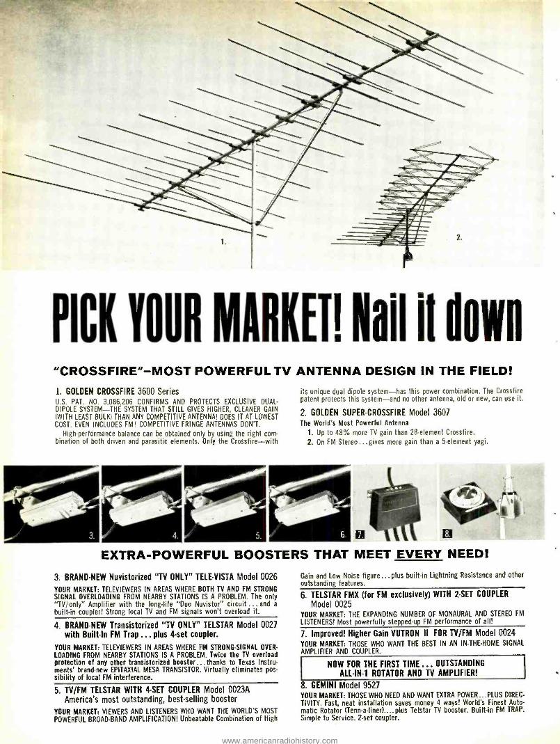
PICK YO UR M ARKETI Nail it down "CROSSFIRE" -MOST POWERFUL TV ANTENNA DESIGN IN THE FIELD!
1. GOLDEN CROSSFIRE 3600 Series U.S. PAT. NO. 3,086,206 CONFIRMS AND PROTECTS EXCLUSIVE DUAL -
DIPOLE SYSTEM -THE SYSTEM THAT STILL GIVES HIGHER, CLEANER GAIN (WITH LEAST BULK) THAN ANY COMPETITIVE ANTENNA! DOES IT AT LOWEST COST. EVEN INCLUDES FM! COMPETITIVE FRINGE ANTENNAS DON'T.
High -performance balance can be obtained only by using the right corn - bination of both driven and parasitic elements. Only the Crossfire -with
its unique dual dipole system -has this power combination. The Crossfire patent protects this system -and no other antenna, old or new, can use it.
2. GOLDEN SUPER -CROSSFIRE Model 3607 The World's Most Powerful Antenna
1. Up to 48% more TV gain than 28- element Crossfire.
2. On FM Stereo...gives more gain than a 5- element yagi.
8.
EXTRA -POWERFUL BOOSTERS THAT MEET EVERY NEED!
3. BRAND -NEW Nuvistorized "TV ONLY" TELE -VISTA Model 0026
YOUR MARKET: TELEVIEWERS IN AREAS WHERE BOTH TV AND FM STRONG
SIGNAL OVERLOADING FROM NEARBY STATIONS IS A PROBLEM. The only "TV /only" Amplifier with the long -life "Duo Nuvistor" circuit ... and a
built -in coupler! Strong local TV and FM signals won't overload it.
4. BRAND -NEW Transistorized "TV ONLY" TELSTAR Model 0027 with Built -In FM Trap ... plus 4 -set coupler.
YOUR MARKET: TELEVIEWERS IN AREAS WHERE FM STRONG- SIGNAL OVER-
LOADING FROM NEARBY STATIONS IS A PROBLEM. Twice the TV overload protection of any other transistorized booster... thanks to Texas Instru- ments' brand -new EPITAXIAL MESA TRANSISTOR. Virtually eliminates pos- sibility of local FM interference.
5. TV /FM TELSTAR WITH 4 -SET COUPLER Model 0023A America's most outstanding, best -selling booster
YOUR MARKET: VIEWERS AND LISTENERS WHO WANT THE WORLD'S MOST
POWERFUL BROAD -BAND AMPLIFICATION! Unbeatable Combination of High
Gain and Low Noise figure... plus built-in Lightning Resistance and other outstanding features.
6. TELSTAR FMX (for FM exclusively) WITH 2 -SET COUPLER
Model 0025 YOUR MARKET: THE EXPANDING NUMBER OF MONAURAL AND STEREO FM
LISTENERS! Most powerfully stepped -up FM performance of all!
7. Improved! Higher Gain VUTRON II FOR TV /FM Model 0024 YOUR MARKET: THOSE WHO WANT THE BEST IN AN IN- THE -HOME SIGNAL AMPLIFIER AND COUPLER.
NOW FOR THE FIRST TIME ... OUTSTANDING
ALL -IN -1 ROTATOR AND TV AMPLIFIER!
8. GEMINI Model 9527 YOUR MARKET: THOSE WHO NEED AND WANT EXTRA POWER...PLUS DIREC-
TIVITY. Fast, neat installation saves money 4 ways! World's Finest Auto- matic Rotator (Tenn- a- liner)....plus Telstar TV booster. Built -in FM TRAP.
Simple to Service. 2 -set coupler.
www.americanradiohistory.com
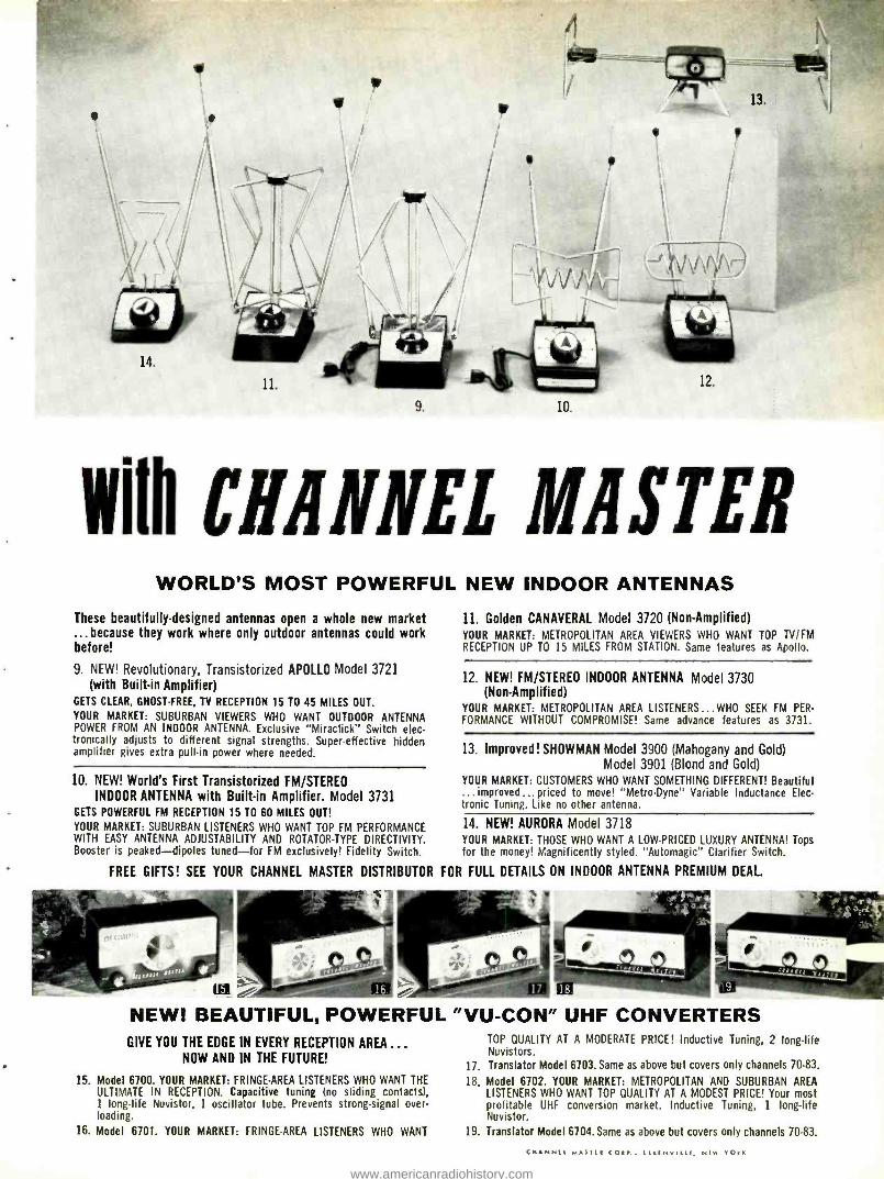
With CHANNEL MASTER WORLD'S MOST POWERFUL NEW INDOOR ANTENNAS
These beautifully -designed antennas open a whole new market ...because they work where only outdoor antennas could work before!
9. NEW! Revolutionary, Transistorized APOLLO Model 3721 (with Built -in Amplifier)
GETS CLEAR, GHOST -FREE, TV RECEPTION 15 TO 45 MILES OUT.
YOUR MARKET: SUBURBAN VIEWERS WHO WANT OUTDOOR ANTENNA POWER FROM AN INDOOR ANTENNA. Exclusive "Miraclick" Switch elec- tronically adjusts to different signal strengths. Super -effective hidden amplifier gives extra pull -in power where needed.
10. NEW! World's First Transistorized FM /STEREO INDOOR ANTENNA with Built -in Amplifier. Model 3731
GETS POWERFUL FM RECEPTION 15 TO 60 MILES OUT!
YOUR MARKET: SUBURBAN LISTENERS WHO WANT TOP FM PERFORMANCE WITH EASY ANTENNA ADJUSTABILITY AND ROTATOR -TYPE DIRECTIVITY. Booster is peaked -dipoles tuned -for FM exclusively! Fidelity Switch.
11. Golden CANAVERAL Model 3720 (Non -Amplified) YOUR MARKET: METROPOLITAN AREA VIEWERS WHO WANT TOP TV /FM RECEPTION UP TO 15 MILES FROM STATION. Same features as Apollo.
12. NEW! FM /STEREO INDOOR ANTENNA Model 3730 (Non -Amplified)
YOUR MARKET: METROPOLITAN AREA LISTENERS...WHO SEEK FM PER- FORMANCE WITHOUT COMPROMISE! Same advance features as 3731.
13. Improved! SHOWMAN Model 3900 (Mahogany and Gold) Model 3901 (Blond and Gold)
YOUR MARKET: CUSTOMERS WHO WANT SOMETHING DIFFERENT! Beautiful ... improved ... priced to move! "Metro- Dyne" Variable Inductance Elec- tronic Tuning. Like no other antenna.
14. NEW! AURORA Model 3718 YOUR MARKET: THOSE WHO WANT A LOW- PRICED LUXURY ANTENNA! Tops for the money! Magnificently styled. "Automagic" Clarifier Switch.
FREE GIFTS! SEE YOUR CHANNEL MASTER DISTRIBUTOR FOR FULL DETAILS ON INDOOR ANTENNA PREMIUM DEAL.
NEW! BEAUTIFUL, POWERFUL GIVE YOU THE EDGE IN EVERY RECEPTION AREA ...
NOW AND IN THE FUTURE!
15. Model 6700. YOUR MARKET: FRINGE -AREA LISTENERS WHO WANT THE ULTIMATE IN RECEPTION. Capacitive tuning (no sliding contacts), 1 long -life Nuvistor, 1 oscillator tube. Prevents strong -signal over- loading.
16. Model 6701. YOUR MARKET: FRINGE -AREA LISTENERS WHO WANT
"VU -CON" UHF CONVERTERS TOP QUALITY AT A MODERATE PRICE! Inductive Tuning, 2 long -life Nuvistors.
17. Translator Model 6703. Same as above but covers only channels 70 -83.
18. Model 6702. YOUR MARKET: METROPOLITAN AND SUBURBAN AREA LISTENERS WHO WANT TOP QUALITY AT A MODEST PRICE! Your most profitable UHF conversion market. Inductive Tuning, 1 long -life Nuvistor.
19. Translator Model 6704. Same as above but covers only channels 70 -83.
(MANNE[ MASILI CORI., (L(WNVILt,. NEW YOE
www.americanradiohistory.com
Even as familiar a piece of test equipment as a v.o.m. has undergone some radical changes and improvements recently.
A NEW LOOK" IN V.O.M.'S
IT WAS a dull and gloomy late fall day outside, and a bit
of coming -of- winter melancholy apparently had seeped
indoors and was weighing down the spirits of \lac and
Barney working silently at the service bench. They needed a
cheerful diversion, and it was not long coming. "One side, woman!" they heard a high -pitched masculine
voice saying to Matilda in the front office. "I'm here to have words with your niggardly Scottish boss who obviously doesn't pay you enough to keep you in decent lipstick and high heels. I assume old MacGregor is back there in his lair gypping the gullible public as usual; so I'll go right in."
The door opened to frame a rather plump, short man with a bristling crew -cut and a pair of bright eyes sparkling mis-
chievously through his glasses. "'\\'ell bless my shoe laces!' Tom exclaimed brokenly, if it
isn't Mr. Damon!' How are you, Ron ?" As. Mac ended this strange, disjointed speech, he grasped the band of the stran- ger and pumped it vigorously. "It's all right, Matilda," he reassured the girl standing in the doorway; " hé s harmless. Barney, this is an old and good friend of nine, Ron Damon."
"Lay off that Tom Swift jive, will yon ?" Ron said to Mac while he was shaking hands with Barney. "You want to give
our ages away, or something? Speaking of ages, boy, get up off that stool and let your elder sit down."
Dazedly Barney obeyed. "\ \'hat good luck brings you here, Ron ?" \lac asked. "On my way home from Chicago, I noticed your sleepy
little hamlet wasn't far out of the way; so, lion,' I said to my-
self, 'it's your duty. You see so much, and poor old \lac sitting down there in the electronic doldrums sees so little. Go to him. Take him the word. Open the window just a little and let him look out.' "
\ \'hile talking, Ron had been unfastening a cardboard car- ton he had with him; and now he lifted out a gleaming v.o.m.
"Feast your eyes on this little jewel and eat your heart out," he continued.
"We've seen a v.o.m. before," Barney sniffed. "Ah rash, impetuous, ignorant youth! You have not seen a
V.0.111. like this before. Hold your rude tongue and watch while I set the meter to the ultra- sensitive 100 -microampere range and touch the probes to my tongue. See the pointer being deflected by the very weak battery action of mouth acids reacting with the prod tips ?"
"It figures, with your acid tongue," Mac offered. Ron did not reply. Instead he took the prods from his
month and jabbed them into a 117-v. a.c. receptacle on the rear of the bench. The meter pointer flickered, and there was a clicking sound from the v.o.m. Mac and Barney exchanged horror- stricken looks.
"Now you've clone it!" Barney exclaimed. "You must be completely kooky. Anyone who would do that to a meter would kick a dog or slap a baby."
Ron still said nothing. He merely pushed in a little white button above and to the right of the function switch and stuck the prods back against his tongue. The pointer swung easily up -scale as before. He switched to the x 1K ohmmeter
60
range, zeroed the pointer with the test prods shorted, and again thrust the prods into the a.c. receptacle. Once more there was a clicking sound from the meter; but when the white button was pushed in, the ohmmeter performed nor- mally.
"This, my open -mouthed friends, is Triplett'.s brand -new Model 630 -PLK 20.000 ohms- per -volt v.o.m. in which all ranges are protected against accidental damage to the meter and associated components," Ron lectured. "The 1 and 10
amp ranges are protected by fuses. The ., 100K ohms and the 1000 - and 1000 -volt a.c. and d.c. ranges are self- protecting because the high resistance of these circuits keeps current below damaging levels.
"All other ranges are protected by a resettable, latching - type, transistor- operated relay which opens the input circuit whenever an overload of two to four times is impressed on the 50- microampere meter movement -an overload it can easily take. Finally, a diode network across the meter movement bypasses instantaneous transient voltages and prevents their damaging the movement or bending the pointer.
"The special cut -out circuit is not polarity sensitive and works equally well with a.c. or d.c. The relay itself is a special job with minimum momentum and fast action designed to
open in a very few milliseconds. It and the x 100K -ohms
range are both powered by a :30-volt battery which can be
expected to last for several years. Satisfactory condition of
the battery for operating the relay is indicated by ability to
zero the pointer on the x 100K -ohms range. "It's easy to see this is the ideal meter for a careless, fiddle -
footed, ooly- witted technician, as your assistant here un- doubtedly is; but even we old timers are likely, in the excite- ment of closing in on an elusive trouble, to forget to change the meter from `Ohms' when we measure volts and end lip
with a bent pointer or worse. On top of that, this little pack- age of carelessness- insurance will reveal the presence of me-
ter- wracking current surges easily overlooked. For instance, the other clay I wanted to see if a transistor radio was drawing its rated 4 ma.; so I set the 630 -PLK for 10 ma. and placed it in series with one of the battery leads. The relay kicked out when the set was turned on, indicating a current of at least
20 ma.; yet when I tried again on the 100 ma. range, and then came down to the 10 ma. range, the proper 4 ma. was
indicated. Charging of a 100 -µf. capacitor directly across the battery input was shooting a high- current pulse of such short
duration through the meter the pointer never had time to
show it; yet that pulse exerts great strain on the jeweled bearings and other parts of a conventional v.o.m. without your knowing it exists."
" \\'e'll not .crane with that," lac broke in hastily as he saw
Barney's neck turning redder and redder. "I suppose you're familiar with the Triplett 630 -NS v.o.m. we've been using for
a couple of months." He opened a cupboard and took out a
v.o.m. that closely resembled, in appearance, the one Ron
had. "No; can't say I am," Ron admitted grudgingly. "It has some features we like," Mac said. "The meter move -
CIRCLE NO. 101 ON READER SERVICE PAGE -30.
www.americanradiohistory.com
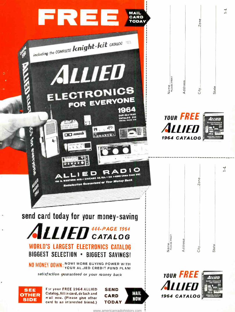
MAIL CARD TODAY
ALLI E D RAD I O 100 N EIESTERM AVE.. CHICAGO S0. ILL HA 1 -SE00 (Ares Cods SW
Satisfaction Guaranteed or Your Money Back
send card today for your mDney- saving
AIL/ Ell 444 -PAGE 1964
CATALOG WORLD'S LARGEST ELECTRONICS CATALOG
BIGGEST SELECTION BIGGEST SAVINGS!
NO MONEY DOWN. NOW! MORE BUYING POWER WITH YCUR AL_IED CREDIT FUND PL4N!
satishction guaranteed or your money back
SEE OTHER SIDE
F)r your FREE 1964 ALLIED Catalog, fill in card, detach and trail now. (Please give other card to an interested friend.)
SEND CARD TODAY
z z a
Q)
EW ta z°
rn y a)
a) C o N
YOUR FREE
/.ILL /ED 1964 CATALOG
a) C o N
YOUR FREE
411/ED 1964 CATALOG
www.americanradiohistory.com
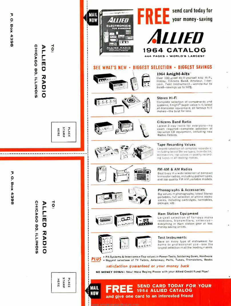
-I o
x m
m
i
o
FREE send card today for
your money- saving
/.ILL /ED 1964 CATALOG 444 PAGES WORLD'S LARGEST
SEE WHAT'S NEW BIGGEST SELECTION BIGGEST SAVINGS - , \. I(' --'
rr.C.rcP : !i
1964 knight -kits -
Over 100 great do- it- yourself kits: Hi -Fi, Hobby, Citizens Band, Amateur, Inter- com, Test Instrument -wonderful to build- savings up to 50 %.
Stereo Hi -Fi Complete selection of components and systems; Knight' super -value hi -fi; latest all -transistor equipment; all famous hi -fi makes -the best for less.
Citizens Band Radio Latest 2 -way radio for everyone -no exam required -complete selection of top -value CB equipment, including new Walkie- Talkies. i _ r.VV If
1.) t
Tape Recording Values Largest selection of complete recorders. including latest Stereo types; tape decks; accessories; top values in quality record - ing tapes in all leading makes.
FM -AM & AM Radios Best buys in a wide selection of compact transistor radios, including pocket types. and top quality FM -AM portable models.
Phonographs & Accessories Big values in phonographs; latest Stereo portables; full selection of phono acces- sories, including cartridges, turntables, pickups, etc.
Ham Station Equipment Largest selection of famous -make receivers, transmitters, antennas - everything in Ham station gear at low, money -saving prices.
Test Instruments Save on every type of instrument for home or professional use -see the largest selection in all the leading makes.
PLUS PA Systems & Intercoms Top values in Power Tools, Soldering Guns, Hardware Biggest selection of TV Tubes, Antennas; Parts, Tubes, Transistors, Books
satisfaction guaranteed or your money back
NO MONEY DOWN : Now! More Buying Power with your Allied Credit Fund Plan!
FREE 1964DALLIED CATALOG FOR YOUR
and give one card to an interested friend
www.americanradiohistory.com
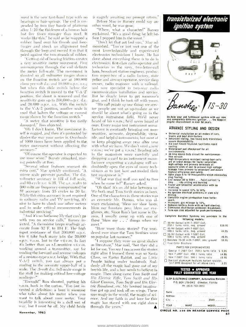
ment is the new taut -band type %vith no bearings or hair -springs. The coil is sus- pended by two tiny bands of platinum alloy 1/10 the thickness of a hunl:ut hair but five times stronger than steel. It ivorks like this," he said as he snapped a
rubber band over his thumb and fore- finger and stuck an alignment tool through the loop and moved it so that it pried against the two strands of rubber.
"Getting rid of bearing friction creates a very sensitive meter movement. Five microamperes through the coil deflects the meter full -scale. The movement is shunted so all voltmeter ranges shown on the function switch are at 100,000 ohms- per -volt d.c. and 10,000 o.p.v. a.c.; but when this slide switch below the function switch is moved to the 'V -A /2' position, the shunt is removed and the sensitivity goes up to 200,000 o.p.v. d.c. and 20,00( o.p.v. a.c. With the switch in the V -A /2 position, another scale is used that halves the voltage or current range shown by the function switch."
"A meter that sensitive is too easily damaged," Ron objected.
"Oh I don't know. The movement it- self is rugged, and then it's protected by diodes the way your meter is. Overloads of 1000 times have been applied to the meter movement without affecting the ace'11acy."
"Of course the operator is expected to use some sense," Barney remarked, star- ing pointedly at Ron.
"Several other features warrant its extra cost," \lac quickly continued. "A mirror scale prevents parallax. The d.c. voltmeter accuracy is 1!_% of full scale, and (i0 -cycle a.c. is 3 %. The a.c. scales to 300 volts are frequency- compensated for 57 accuracy from 35 cycles to 20 kc. While this extra accuracy is not required in ordinary radio and TV servicing, it's nice to have to check our other meters and to make critical measurements in in(Instrial servicing."
"Alid it's no hothouse lily that can't go with you on service calls," Barney in- jected. "A thermistor keeps readings ac- curate from 32'F. to 104' F. The high input resistance of that 200,000 o.p.v. lets it take back many jobs the 20,000 o.p.v. v.o.m. lost to the v.t.v.m. In fact it's better than an r.f.- sensitive v.t.v.m. working around a transmitter, say for reading the forward and reverse voltages of a resistor -type s.w.r. bridge. With that V -A /2 switch, you can always put a reading in the accurate upper -half of a scale. The .3 -volt d.c. full -scale range is the stuff for making critical low -voltage readings -"
"Enough!" Ron shouted, putting his v.o.m. back in the carton. "I've just in- vented a definition: a bore is someone who talks about his meter when you want to talk about your meter. Your twaddle is interesting in a dull sort of way, but I must be off. My child bride
November, 1963
is eagerly awaiting my prompt return." Before Mac or Barney could say an-
other word, he was gone. "Whew, what a character!" Barney
exclaimed. "It's a good thing he left be- fore I popped him in the snoot."
"Don't let that act fool you," NIac ad- monished. "You've just met one of the most knowledgeable and experienced electronics technicians I know. He has clone about everything there is to do in electronics: first -class radio operator and technician in the navy, two- letter -call ham, broadcast station engineer, produc- tion supervisor of a radio factory, state police and airways operator, service shop owner, radio engineer with a railroad. and now specialist in two -way radio communication installation and service. But he dearly loves to get someone's goat, and I think he took off with yours.
"His call points up one thing: we sere ice people are not as up -to -date as 'a
should be about what's going on in the service instrument field. We'd never heard of his v.o.m.; he'd never heard of ours. Every major test instrument manu- facturer is constantly bringing out more sensitive, accurate, dependable, versa- tile, and helpful instruments; but most of us keep plugging away year after year with what we have. We don't need a new v.o.m.; we've got a v.o.m.! Reading ads in the magazines more carefully and dropping a card to an instrument manTl- facturer requesting a catalogue will un- doubtedly open the eyes of many tech- nicians as to just how out -moved their test equipment is."
"What was that stuff you said to Ron when he came in ?" Barney asked.
"Oh that! It's an ,31d joke between us. We both read Toni Swift stories as boys. One of the characters in these stories was an eccentric \lr. Damon, who was al- ways exclaiming, 'Bless my shoe laces; bless my fountain pen; bless my eve - glasses, etc. Since Ron's last name is Da- mon, I usually come up with one of these 'bless my . . things when we i
meet." "How were those stories? I've won-
dered ever since the Tom Swifties were so popular last summer."
"I suppose they were no great shakes as literature," Nfac said, "but they did a lot for me. You see I ran across the stories right after I learned there was no Santa Claus, no Easter Rabbit, and no Little People hiding under toadstools. Sud- denly all the magic had gone out of my boyish life, and a boy needs to believe in magic. Then along came Torn Swift and His Electric Rifle, Tom Swift and His Giant Cannon, Toni Swift and Ilis Elec- tric Runabout, etc. My bruised imagina- tion got up and took off on wings. There was magic in the world, the magic of sci- ence. And my faith in and love for this magic has stayed with me right down through the years."
transistorized electronic ignition system
)
Update your old fashioned system with our new and completely different ignition .. the biggest engine improvement in over 50 years.
ADVANCE STYLING AND DESIGN
Universal installation on all makes of cars. trucks and boat distributors. Advanced styling, two heavy.duty transistors assure dependability. Die cast finned heatsink facilitates rapid cooling. Waterproof and shockproof for all environments. 30 Amp Heavy-Duty circuit for maintenance- free service. Hightemperature resistant racingtype coils are of latest design for faster saturation. High voltage and primary terminals at opposite ends of coil to prevent high voltage leakage from primary to secondary and assure highest efficiency and safety. Open plugs 5 to 10 thousandths which eliminates plug fouling. Coil output 30 to 55KV ... Point current 1/4 Amp ... rids pitting and burning. Faster and Smoother acceleration with no misfiring. Increase in speed 10', to 30 ° °. No ignition overheat problems in slow city driving. Complete engine combustion from hotter spark. Increases gas mileage to 10 %. Reduces battery drain with no hard starting. Eliminates distributor -condenser breakdown. Tuneups stay adjusted for peak performance.
Complete Banshee Systems are available in the following models:
30 KV Output with F 250T Coil, 250:1 turns ratio, neg. ground $39.95 45 KV Output with F -400T Coil, 400:1 turns ratio, neg. ground .. 44.95 55 KV Output with FSOOT Coil, 500:1 turns ratio, neg. ground 49.95 Banshee TS -30 with F -SOOT, pos. ground 59.95 Free Color Brochure
PARTS FOR EXPERIMENTERS
E Special F- 250 T Coil 250:1 turns ratio S 9.95 E New F -4001 Coil. 400:1 turns ratio 14.95
New F.500T Coil, 500:1 turns ratio 19.95 Diecast aluminum heatsink ballast resistor, .517 OHM designed for all above coils 3.25
TESTED APPROVED FULLY GUARANTEED ONE YEAR
REP ELECTRONIC COMPANY, Automotive Division P.O. BOX 178 -EW2 Ellenton, Florida
Ph 8131722 -1813
Name
Address
ty State .
YEAR MAKE MODEL.
CIRCLE NO. 150 ON READER SERVICE PAGE 63
www.americanradiohistory.com
LAMPKIN METERS
can MOM monEY
In YOUR POCKET!
THE AMAZING EXPLOSION IN MOBILE
UES. RIGHT NOW OVER 2.788.000
(PLUS 47.000 NEW INSTALLATIONS
MUST HAVE PERIODIC MAINTENANCE AND
FREQUENCY AND MODULATION.
Frequency measurements and adjustments can only be made
by properly equipped -and licensed- servicemen. Quite often
maintenance is done on a term contract basis- assuring steady,
competition -free income.
RADIO CONTIN-
TRANSMITTERS EACH MONTH)
CHECKS ON
Almost every two -way radio tower or on- tenna in your area can mean money to
you-
TO LEARN HOW YOU CAN CASH IN
ON THIS OPPORTUNITY
MAIL COUPON TODAYI
ccomsmose
LAMPKIN LABORATORIES, INC. MFM Division, Bradenton, Florida
At no obligation to me, please send free booklet "HOW TO MAKE MONEY IN MOBILE RADIO MAINTENANCE" and data on Lampkin meters.
L
NAME
ADDRESS
CITY. STATE
LAMPKIN 105 .8 Frequency Meter. 0.1 to 175 MC and up.
3260.00. Accessory PPM Me-
ter for 0.0001% accuracy on
split- channels. 1147 00
LAMPKIN 205 -A FM Modula-
tion Meter. Tunes 25 to 500
MC. With four modulation scales. 0 -1.25, 2.5. 12.5, and
^5.0 KC. 1310.
LAMPKIN LABORATORIES, Inc. MFM Division
BRADENTON, FLORIDA
CIRCLE NO. 132 ON READER SERVICE PAGE
NEED A 110 VOLT
A.C. OUTLET?
In CAR, BOAT or TRUCK,
YOU HAVE IT WITH A
POWER ..,V1,0 INVERTER
Actually gives you 110 volt, 60
cycle A.C. from your 6 to 12 volt D.C. battery! Plug inverter into cigarette lighter, and operate lights, electric shavers, record players, electric tools, portable TV,
radios, testing equipment, etc. Frequency stable within one cycle.
Models from 15 to 600 $I 9 9S watts, priced as low as `LIST
See Your Electronic Parts Dealer or Jobber, or Write
CORPORATION 1058 Raymond Ave.
St. Pout 8. Minn.
In Canada, Atlas Radio Corp. Ltd. - Toronto, Ont
CIRCLE NO. 154 ON READER SERVICE PAGE 64
RCA, G.E. etc. jobber boxed tubes at 65% dis-
count off current RCA price list. Send your trial order NOW. Free catalog listing thousands of
parts, needles, crystals, tubes, kits etc. "Arctur- us" tubes at 78% discount. Send for catalog.
HEADLINE BUYS FROM OUR CATALOG
FLYBACK TRANSFORMER KITS YOUR 299 PER
Worth $30.00 PRICE KIT
Kit :MI- Motorola -2 late -type flyback transformers. Kit :502 -RCA -2 late -type flyback transformers. Kit :503 -CBS -2 late -type flyback transformers. Kit ;504- Zenith -2 late type flyback transformers. Kit :SOS- Emerson -2 late -type flyback transformers. Kit _506 -Sylvania -2 late -type flyback transformers. Kit : 507 -Philco -2 late -type flyback transformers. Kit :SOB-Westinghouse-2 lote -type flyback transform- ers. Kit :509- Dumont -2 late -type flyback transformers.
TV YOKE KITS 70 and 90 . a once -in -while buy. The six yokes listed can be used directly or adapted for use In almost every TV set ever built. except 110 types. Their average cost to you is ordinarily about $15.00 each. Our price $1.991, individually boxed, and in perfect condition. Your savings per kit; $26.00 ap- proximately. Your cost per kit; $3.99.
Unit ±±Y -1 -One 90 Zenith and one 70° G.E. yoke. both for $3.89
Unit _Y -2 -One 90' Motorola and one 70' Westinghouse yoke, both for $3.99
Unit _Y -3 -One 90 Muntz and one 90° Philco yoke, both for $3.99
7" TV TEST TUBE 699 YOUR
WORTH $25.00 COST
7- TV Renata Test Picture Tube: New -Not Rebuilt 17R1'71 -Flat Face -Electra- alagnetle Focus. Uses focus coil of net
currently under tdsTV
anode voltages-works pen -wW In any TV nel except 1111 Angie-Complete with ncket ad -,iter ha Men,. Ready to use at once -
Guaranteed 1 year against all detects shipped post -paid, if order is Pre -paid.
EW Lab Tested (Continued from page 24)
15,000 -cps limit of our microphone cali- bration. Except for a dip of about 5 db at 6000 cps, the response was within ± 2 db from 200 to 15,000 cps. It was not possible to determine the actual crossover frequency from examination of
the response curve. The tone -burst response pictures re-
veal the outstanding transient response of the tweeter. The 3.8 -kc. tone burst shown is typical of the tweeter's response throughout its range. The woofer tran- sient response, shown at 250 cps, is not quite as good, but may have been slightly influenced by room characteris- tics.
The listening quality of the system is
smooth and well balanced, as the re- sponse curve would suggest. Its sound is
neither boomy nor thin, free from screechiness or stridency, yet with a
pleasing crispness and liveliness. The speaker has moderate efficiency. The manufacturer states that amplifiers rated at from 10 to 65 watts may be used and we found that a good 15 -watt am- plifier was adequate to drive the speaker.
The ADC -14 is attractively and dis- tinctively styled, measuring 13W' wide x 25" high x 123í" deep. It is finished in
oiled walnut and may be mounted either horizontally or vertically. The price is
$175. A base is included for floor mount- ing.
ARCTURUS ELECTRONICS CORP. D ZPT.
502 -22nd ST., UNION CITY, NEW JERSEY 07087 CIRCLE NO. 103 ON READER SERVICE PAGE
CIRCLE NO. 161 ON READER SERVICE PAGE -.
ENGINEERING SALARIES UP
A:(:OItl)I.G to statistics gathered by -
the Illinois Institute of Technology al heir engineering graduates, it pays to he an engineer if current starting sala- ries are any criterion.
By LIT findings, engineers start out with a salary three times greater than the average national per capita income re-
corded by the Department of Commerce. The average engineering incomes vary
according to specialized fields, with elec- trical engineers taking home the biggest pay cheeks. In 1962 electrical engineers received an average starting salary of $585 while this year the figure has risen to $607.
EX -CB -ER ARRESTED
THE Federal Conununieations Com- mission has announced the arrest of
Warren J. Currence of Elkins, W. Va. for the alleged operation of an unlicensed CB station in Elkins. Three CB trans- mitters were seized.
This was Currenee's second appearance before the U.S. Commissioner in four months. Earlier he ran afoul of the e -
munieations laws which resulted in his being charged with using obscenity on the air. This caused revocation of his CB
license by the FCC on July 22. His illegal operations brought complaints by hun- dreds of CB licensees in the central West Virginia area.
www.americanradiohistory.com
LEADS IN TRANSISTOR STEREO
TUNER -AMPLIFIER by Heathkit
FIRST IN KIT FORM! ALL -TRANSISTOR AM -FM & FM STEREO TUNER PLUS ALL -TRANSISTOR 40 -WATT STEREO AMPLIFIER -ALL IN ONE SMART WALNUT CABINET FOR JUST $195.00 Now in time for Christmas giving, Christmas listening! Two 20 -watt power amplifiers...two separate preamplifiers...plus wide -band AM, FM, and FM Stereo...all beautifully housed in this one, compact Heathkit All- Transistor Stereo Re- ceiver. For Heathkit this means another first! For you it means experiencing the uncompromising realism of "tran- sistor sound" in a handsomely styled receiver that won't overheat...just the coolest, fastest, most "hum- free" oper- ation possible! Just the purest, most "solid sound" possible! This is the why of transistor stereo. This is why you should move up to the new AR -13 Receiver. And the traditional Heathkit economy makes this advanced performer easy to own ... just $195.00
All the electronics you need for a complete music system are "Heath- Engineered" into this handsome unit... just add two speakers and a phonograph or tape recorder! And there's plenty of advanced features to match the advanced perform- ance of the AR -13. You'll like the way this unit automatically switches to stereo, thus eliminating any manual operation. In addition the automatic stereo indicator light silently sig- nals when stereo is being received. For versatility there's three stereo inputs (mag. phono and two auxiliary) plus two filtered tape recorder outputs for direct "off- the -air" beat - SPECIFICATIONS- Amplifier: Power output per channel (Heath Rating): 20 watts /8 ohm load, 13.5 watts /16 ohm load. 9 watts,4 ohm load. (IHFM Music Power Output): 33 watts,8 ohm load, 18 watts /16 ohm load. 16 watts /4 ohm load ® 0.7% THD, 1 KC. Power response: j1 db from 15 cps to 30 KC ® rated output; ±3 db from 10 cps to 60 KC ® rated output. Harmonic distortion (at rated output): Less than 1% ® 20 cps; less than 0.3 %4® 1 KC; less than 1 %® 20 KC. Into/modulation distortion (at rated output): Less than 1 %, 60 6 6.000 cps signal mixed r:l. Hum { noise: Mag. phono, 50 db below rated output; Aux. inputs, 65 db below rated output. 1 sepa- ration: 40 db ® 20 KC, 60 db ® 1 KC, 40 db ® 20 cps. Input sensitivity (for SS watts output per a I, S ohm load): Mag. phono, 6 MV; Aux. 1, .25 v; Aux. 2, .25 v. Input Impedance: Map phono, 35 K ohm; Aux. 1, 100 K ohm; Aux. 2, 100 K ohm. Outputs: 4, 8. 6 16 ohm and low impedance tape recorder outputs. Controls: 5- position Selector; 3- position Mode: Dual Tandem Volume; Bass 6 Treble Controls; Balance
r
free stereo recording. Dual -tandem controls provide simul- taneous adjustment of volume, bass, and treble of both channels. Balancing of both channels is accomplished by a separate control. The AM tuner features a high -gain RF stage and high -Q rod antenna.
Other quality features include a local- distance switch to prevent overloading in strong signal areas; a squelch control to eliminate between- station noise; AFC for drift -free re- ception; heavy die -cast flywheel for accurate, effortless tun- ing; pin -point tuning meter; and external antenna terminals for long- distance reception. For added convenience the secondary controls are "out -of- the -way" under the hinged lower front panel to prevent accidental system changes.
Building the AR -13 is quick and easy with the pre- assem- bled FM "front -end" and 3 -stage AM -FM I.F. strip, plus circuit board construction. Styled in Heathkit's new low - silhouette design, the beautiful walnut cabinet accented with the extruded gold -anodized aluminum front panel makes the AR -13 a handsome addition to any home decor. This Christ- mas, move up to the better listening of "transistor sound" with the new AR -13 Stereo Receiver...another example of superb Heathkit quality at unmatched savings. Kit AR -13, 30 lbs., no money dn., $19 mo. $195.00 Control; Phase Switch; Input Level Controls (all inputs except Aux. 2); PushPull ON /OFF Switch. FM: Tuning range: 88 mc to 108 mc. IF hp : 10.7 mc. Antenna: 300 ohm balanced (internal for local reception). Quieting sensitivity: 2% un for 20 db of Quieting, 3% uv for 30 db of Quieting. Bandwidth: 250 KC ® 6 db down (full Quieting). Imago rejection: 30 db. IF rejection: 70 db. AM suppression: 33 db. Harmonic distortion: Less than 1 %. Multiplex: bandpass: ±% db. 50 to 53,000 cps. Ch I separation: 30 db, 50 to 2,000 cps: 25 db ® 10 KC. II KC suppression: 50 db down, from output ® 1 KC. 3$ KC suppression: 45 db down, from output ® 1 KC. SCA rejection: 30 db. AN: tuning range: 535 to 1620 KC. IF fr : 455 kc. Sensitivity: 1400 KC. 3.5 uv; 1000 KC, 5 uv: 500 KC. 10 un- standard IRE dummy antenna. Bandwidth: 8 KC ® 6 db down. Image rejection: 30 db ® 600 KC. IF rejection: 45 db ® 600 KC. Harmonic distortion: Less than 1 %. Overall dimensions: it L x 5 %' H o 14 %' D.
HEATHKIT-1964
ea c M_
T Tt
NEW! FREE 1964 HEATH KIT CATALOG. See the latest new products in Heathkit's wide, wonder- ful line. Over 250 do -it- yourself kits for stereo/ hi -fi, marine, TV, elec- tronic organs, amateur radio, test instruments, educational, and home and hobby items that will save you up to 50 %. Send for your free copy today!
HEATH COMPANY Benton Harbor 15,lchigan 49023 1, Enclosed is $195.00, plus postage. Please send Model No. AR -13. [ ; Please send Free Copy of New 1964 Catalog.
Name
Address
City State
November, 1963 CIRCLE NO. 122 ON READER SERVICE PAGE 69
www.americanradiohistory.com
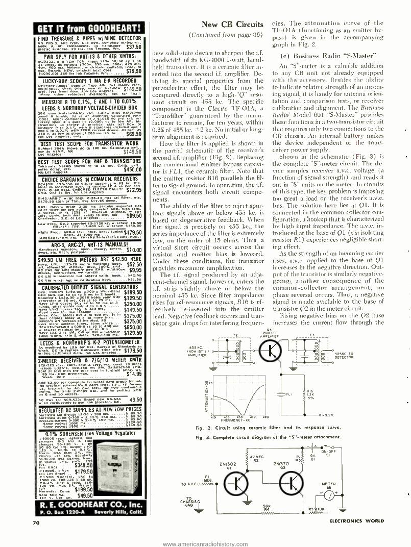
GET IT from GOODHEART! . FIND TREASURE & PIPES W /MINE UEILL IUN ' AN PR5 -3, Tate type, like new. Complete W /InstruC.
book 8 all Components. in handsome $37,50 plastic suitcase, 23 lbs. fob Tacoma, Wn.
PWR SPLIT FOR ART -13 & OTHER XMTRS: 2-20122. p o TCM TCU. input 115e 50/60 ey 1 ph 11 amps. dc outputs 1300e. 350 ma. 500v. 42S ma. 50v, 400 ma. Metered. w Ckt -brkr controls, ready to
510BRAND NEW. original box! Cost $79.50 00.00! 360 lbs lob Tacoma. Wn.
LUCKY -BUY SCOOP! 1 MA E -A RECORDER Esterline- Angus' popular Type OW. 0.1 made. elec.
multi -speed chart drive. new or like -new $149.50 grtd. less front door. fob Los Angeles
( many other recorders available. ask for list.i
MEASURE R TO 0.1%, E AND I TO 0.01% LEEDS & NORTHRUP VOLTAGE- DIVIDER BOX
20K ohm Kelvin- Varley Ott. 3dial, plus handsome 11..01 A knobs: 3d is 3" diameter calibrated each .0001. Major Component Of a 51055.00 test set: ac- curacy spCC IS 1 part in 10.000: dc to low AF. In- structions On theory A praCtiCal Ckts tell how to measure R to 0.1*' with R standards Included and I
and E to 0.017, with ZERO current drawn. As high as 350 y. as low as steps of 200 uv. 10 lbs $69.50 lob Los Angeles. only
BEST TEST SCOPE FOR TRANSISTOR WORK DuMont 304A shows de to 100 NC. Calibrated deft.. use as VTVM, fob $149.50 Los Angeles .... ... .... .. ..
BEST TEST SCOPE FOR VHF & TRANSISTORS Tektronix 514AD shows dc to 10 mc. Calib. deft.. pulse ob Los Angeles $450.00
CHOICE BARGAINS IN COMMUN. RECEIVERS BC453B: 190 -550 kc 6 -tube superhet w 85 kg IFS. ideal as long -wave rcv, as tunable IF & as 2nd con- vert. Wall data. CHECKED ELECTRICALLY! $12.95 Grid. OK! 11 lbs. fah Los Angeles
R- 45 /ARR -7 w /aC sply. 0.55.43 mc; MI filter. etc. $179.50 cash or Time Pay 517.95 down.
RBS: Navy's pride 2 -20 mc 14 -tube superhet has voice filter for low noise, ear -saving ACC. high sens. A select. IF Is 1255 lie. Checked. aligned. w pwr sply. n. S.0
tech Los AnR
1eÿo use. fob $69.50
Low FreRB DZ2 TRFrh15- 6007ke
ke. eheme3550.00
High: Freq.: APR4 rcvr. plug. book, tuning $179.5,10 units. 38.1000 mc
I Add 330 for AM FM. TN -19 A 54 to .reach kmc. PUR. 1
ARC -3, ARC -27, ART -13 MANUALS! Handbooks mainten., oper.. theory. schem. $10.00 dwgs. etc. Each. postpaid
$49.50 LM FREQ METERS ARE $42.50 HERE Navy. LM., 125.20 mg w matching book. $51.50 xtl. schematic. instruct.. plug, 100% grid AC Pwr for LM: Modify new EAO, w silicon $9.95 diodes. Instructions we furnish OK LM w'readable but ragged ealib. book...342.50 OK LM w ',al but no calibration book $27.50
CALIBRATED -OUTPUT SIGNAL GENERATORS Gen. Radio's $750.00 .700 -A Wide Band $199,50 BFO puts out 50 cy to 5 mc in 2 bands.. Boonlons $420.00 .203B heats your VHF $129.50 generator at 70 me. Get .1 to 25 me. .
Navy LP5 covers 91 a Me to 50 mc in 8 $250.00 bands, ultra stable output to 1.0 v Navy LX -2 covers lt,a to 330 mc, $149.50 Metal case for low leakage Meas. Corp. Model 80: 2 to 400 mC. Is In $375.00 their catalog today at a lot more than Daven's AN version of the Mod. 80 $375.00 uses more modern tubes. same range.. Hewlett- Packard -608 -B is 10 to 400 me $650.00 w lowest residual Im. .1 uv to .8 v.. .
Navy LAE-2 AM, C or PM w pulse width.
is rate 8. delay. 520.13001 mg $129.50
LEEDS & NORTHRUP'S K -2 POTENTIOMETER As modified by LAN for Nat. Bureau of Standards in Wash. DC to replace Kolrausyh slide wire $179.50 w two calibrated dials. lob Los Angeles
2 -METER RECEIVER & 2/6/10 METER XMTR SCH 522 rcv, xmtr. rack A case. exC. Bond. 19 tubes include 832A's. 100 -156 mc AM. Satisfaction grid. Sold at less than the tube Cost in surplus! Shpg. wt.
85 lbs. FOB Bremerton. $14.95 Wash. Only .............. .... ...
Add $3.00 for complete technical data group includ- ing original schematics A parts lists. I.F Ott formu- 1.15. instruct. for AC pwr sply, for rcvr continuous tuning. for xmtr 2 -meter use, and for putting xmtr on 6 and 10 meters.
AC Pwr for SCR -522: Brand new RA -62A 49.50 w all cords ready to use. fob Stockton. Cal.
REGULATED DC SUPPLIES AT NEW LOW PRICES Sorensen solid -state 18 -36 v 500 ms. S 69.50 Sorensen 3008 0.300 y =.15% ISO ma. S 89.50 Oressen Barnes 0 -300 v 5:.13/4 150 ma. S 89.50
Same except 1000 ma 5129.50 Same except 1500 ma ..... 5149.50
0.1% SORENSEN Line Voltage Regulator 050005 'ego, agaomI load changes 0.5 kva A line changes 95 -130 v. 1 ph 50 60 cy; adj. output 110- ..
120 v. holds to 0.1 .. Harm. less than 3%. Re- covery .15 sec. Regularly {a 5695.00 less spares. New.
fispares orig. pack. 285
bs. $349.50 La") 10005.' 1 kva
$179.50 Pa
- lob Los Angel .
a( 1500 Special. 150 to 1500 va, 105.125 V 60 cy. 20.3% line A load. 110- I 120 Vo. Max 5% distort.
$199.50 - - Norwalk. Conn. Sola 500 Va. $49.50 117 V. Los An.
R. E. GOODHEART CO., Inc. P. O. Bon 1220 -A Beverly Mills, Calif.
70
New CB Circuits (Continued from page 36)
new solid -state device to sharpen the i.f. bandwidth of its KG -4000 1 -watt, hand- held transceiver. It is a ceramic filter in- serted into the second i.f. amplifier. De- riving its special properties from the piezoelectric effect, the filter may be compared directly to a high -"Q" reso- nant circuit on 455 kc. The specific component is the Clevite TF -01A, a "Transfilter" guaranteed by the manu- facturer to remain, for ten years, within 0.2% of 455 kc. ±2 kc. No initial or long- term alignment is required.
How the filter is applied is shown in the partial schematic of the receiver's second i.f. amplifier (Fig. 2) . Replacing the conventional emitter bypass capaci- tor is FL1, the ceramic filter. Note that the emitter resistor R16 parallels the fil- ter to signal ground. In operation, the i.f. signal encounters both circuit compo- nents.
The ability of the filter to reject spur- ious signals above or below 455 kc. is
based on degenerative feedback. When the signal is precisely on 455 kc., the series impedance of the filter is extremely low, on the order of 15 ohms. Thus, a virtual short circuit occurs across the resistor and emitter bias is lowered. Under these conditions, the transistor provides maximum amplification.
The i.f. signal produced by an adja- cent- channel signal, however, enters the i.f. strip slightly above or below the nominal 455 kc. Since filter impedance rises for off -resonance signals, R16 is ef- fectively re- inserted into the emitter lead. Negative feedback occurs and tran- sistor gain drops for interfering frequen-
cies. The attenuation curve of the TF -01A (functioning as an emitter by- pass) is given in the accompanying graph in Fig. 2.
(c) Business Radio "S- Master"
An "S" -meter is a valuable addition to any CB unit not already equipped with the accessory. Besides the ability to indicate relative strength of an incom- ing signal, it is handy for antenna orien- tation and comparison tests, or receiver calibration and alignment. The Business Radio' Model 601 "S- Master" provides these functions in a two- transistor circuit that requires only two connections to the CB chassis. An internal battery makes the device independent of the trans- ceiver power supply.
Shown in the schematic (Fig. 3) is
the complete "S" -meter circuit. The de- vice samples receiver a.v.c. voltage (a function of signal strength) and reads it out in "S" units on the meter. In circuits of this type, the key problem is imposing too great a load on the receiver's a.v.c. bus. The solution here lies at Ql. It is
connected in the common -collector con- figuration; a hookup that is characterized by high input impedance. The a.v.c. in- troduced at the base of Ql (via isolating resistor R1) experiences negligible short- ing effect.
As the strength of an incoming carrier rises, a.v.c. applied to the base of Q1 increases in the negative direction. Out- put of the transistor is similarly negative - going; another consequence of the common- collector arrangement, no phase reversal occurs. Thus, a negative signal is made available to the base of transistor Q2 in the meter circuit.
Rising negative bias on the Q2 base increases the current flow through the
T2 2ND.F. AMPLIFIER 13
455 KC. FROM IST F
AMPLIFIER
TO AvC
20
2 o
á
C o
455KC.TO DETECTOR
L 0
4 0 430 450 470 FREOUENCY-KC.
480
oFLI Rl6 1.3K 5.
9.2 V.
Fig. 2. Circuit using ceramic filter and its response curve.
Fig. 3 Complete circuit diagram of the "S" -meter attachment.
2N1302
RI MEG
TO CHASSIS?
ONO
47 MEG. R2
IK R3
2N1370
56K R4
02
I ON-OFF 9V Si BI
R51
METER MI
10K
ELECTRONICS WORLD
www.americanradiohistory.com
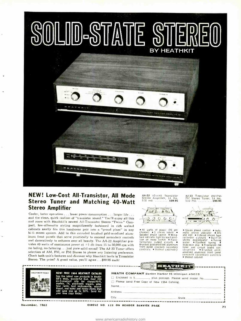
r
L
NEW! Low -Cost All- Transistor, All Mode Stereo Tuner and Matching 40 -Watt Stereo Amplifier Cooler, faster operation ... lower power consumption ... longer life .. .
and the clean, quick realism of "transistor sound." You'll enjoy all this and more with Heathkit's newest All- Transistor Stereo "Twins." Com- pact, low -silhouette styling magnificently fashioned in rich walnut cabinets neatly fits this handsome pair into a "proud place" in any hi -fi stereo system. Add to this extruded brushed gold -anodized alum- inum front panels that serve practically to conceal secondary controls and decoratively to enhance over -all beauty. The AA -22 Amplifier pro- vides 40 watts of continuous power at 11 db from 15 to 30,000 cps with no fading, no faltering ... just pure solid sound! The AJ -33 Tuner offers selection of AM, FM, or FM Stereo to please any listening preference. Check both unit's features and discover why Heathkit leads in Transistor Stereo. The price? A great value, you'll agree ... $99.95 each!
AA -22 40 -watt Transistor Stereo Amplifier, 14 lbs. $10 mo. $99.95
Ai -33 Transistor AM -FM- FM Stereo Tuner, 14 lbs. $10 mo. $99.95
40 watts of power (20 per channel) 5 stereo inputs Speaker phase switch Minia- ture indicator light for each posi- tion on mode switch Trans - formerless output circuits Brushed gold -anodized aluminum front panel conceals secondary controls Walnut cabinetry
NEW! FREE 1964 HEATHKIT CATALOG See the latest new products in Heath - kit's wide, wonderful line. Over 250 do- it- yourself kits for stereo /hi -fi, marine, TV, electronic organs, ama- teur radio, test instruments, educa- tional, and home and hobby items that will save you up to 50 %. Send for your free copy today!
Stereo phase control Auto- matic stereo indicator AFC and AGC Filtered stereo tape recorder outputs Built -in stereo demodulator Tuning meter Flywheel tuning Slide -rule dial Prealigned FM tuner and circuit board con - structicn Brushed gold - anodized aluminum front panel conceals secondary controls
Walnut cabinet
HEATH COMPANY Benton Harbor 15 Michigan 49023 Enclosed is $ _ _, plus postage. Please send model No Please send Free Copy of New 1964 Catalog.
Name
Address
City State
November, 1963 CIRCLE NO. 122 ON READER SERVICE PAGE -a
71
www.americanradiohistory.com
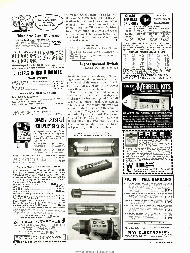
NEW
Los Angeles Plant Now Filling
West Coast Orders
Citizen Band Class "D" Crystals
CITIZEN RAND CLASS "D" CRYSTALS 3rd overtone - .005% tolerance - to meet all FCC requirements. Hermetically sealed HC6 /U holden. !_" pin spacing. .050 pins. (Add 15c per crystal for .093 pins).
All 23 channels in stock: 26.965, 26.975, 26.985, 21.005, 27.015, 27.025, 27.035, 27.055,
27.065, 27.075, 27.085, 27.105, 27.115, 27.125,
21.135, 27.155, 21.165. 27.175, 27.185, 27.205,
21.215, 27.225, 27.255.
Matched crystdl sets for ALL CB units (Specify equip-
ment make and model numbers) $5.90 per sel
$295
CRYSTALS IN HC6 U HOLDERS
SEALED OVERTONE
.486 pin spacing - 050 diameter - .005 °o tolerance
15 to 30 MC 30 to 40 MC 40 to 65 MC
$3.85 ea. $4.10 ea. $4.50 ea.
FUNDAMENTAL FREQUENCY SEALED
From 1400 KC to 2000 KC
.005 °o tolerance $5.00 ea.
From 2000 KC to 10,000 KC,
any frequency, .005% tolerance $3.50 ea.
RADIO CONTROL
Specify frequency. .05 pins spaced '2" (Add 15c for .093 pins) $2.95 ea.
MADE TO ORDER
QUARTZ CRYSTALS
FOR EVERY SERVICE
All crystals made from Grade "A" imported quartz -ground and etched to exact frequencies. Unconditionally guaranteed! Supplied in: FT -243 holders MC -7 holders Pin spacing 1/2" Pin spacing sae
Pin diameter .053 Pin diameter 125
CRIA /AR holder. FT -171 holders Pin spacing 'h" Pin spacing 14,-
Pin diameter .125 Banana pins
CRYSTALS . . Specify holder waisted
of ht to 1,;11t1 K, tolera0,. 54.50 ea. 1x.111 EC to 21I00 KC: tolerance 3.00 ea. 21i111 MI' to 81i50 KI': í- tolerance 3.00 ea. 8051 El' to 11.01111 1:c: 1111c , loi'1,1111 . 3.75 ea.
Amateur, Novice, Technician Band Crystals
.01% Tolerance ... $1.50 ea. - 80 meters (3701- 3749 KC) 40 meters (7152.7198 KC), 15 meters (7034 -7082 KC), 6 meters (8335 -8650 KC) within 1 KC
FT -241 Lattice Crystals in all frequencies from 370 KC
to 540 KC (all except 455 KC and 500 KC) 50c ea.
Pin spacing Ili" Pin diameter .093 Matched pairs - 15 cycles . $2.50 per pair 200 KC Crystals $2.00 ea. 455 KC Crystals $1.25 ea. 500 KC Crystals $1.25 ea.
100 KC Frequency Standard Crystals in HC6 U holders $4.50 ea.
Socket for FT -243 Crystal 15c ea. Dual Socket for FT -243 Crystals 15c ea.
Sockets for MC -7 and FT -171 Crystals .... 25c ea. Ceramic Socket for HC6 /U Crystals 777_7_ 20c ea. IF YOUR PARTS DEALER DOESN'T STOCK Texan Cr3 stall. n'd,r direct alld s,ud us Ills none.
TERMS: :
All ttic. Ails ...Wert
lto, prior sale alnd change of peleo
check, money order car cash ,vat, P'l,n,ent lo 1.011
TWO TO SERVE YOU RUSH YOUR ORDER NOW TO CLOSER PLANT
TEXAS CRYSTALS Div. of Whitehall Electronics Corp. Dept. (R -113)
1000 Crystal Drive, Fort Myers, Florida Area 813 Phone WE 6.2109
4117 W. Jefferson Blvd., Los Angeles, Calif. Area 213 Phone 731.2258
l FOR SHIPMENT VIA FIRST CLASS MAIL AT NO EXTRA
COST ATTACH THIS ADVT. TO YOUR ORDER!
transistor and the meter, in series with the emitter, commences to indicate. Po- tentiometer R5 is used for calibrating the pointer to zero under no- signal condi- tions. When the CB receiver is driven by a 100 -µv. carrier, the meter deflects to an S -9 reading. Other carrier levels or at- mospheric noise are indicated in a pro- portional manner.
CIRCLE NO. 155 ON READER SERVICE PAGE 72
REFERENCES
1. E.C.I., 325 No. MacQuestion Pkwy., Mt. Ver- non, N.Y.
2. Allied Radio Corporation, 100 N. Western Ave.. Chicago 80. III.
3. Business Radio, Inc., P.O. Box 5652, Minne- apolis 17, Minn.
Light- Operated Switch (Continued from page 47)
circuit is almost mandatory. Normal a.g.c. circuits will not work since they all operate off the carrier signal, and in SSB transmission there is no carrier when there is no modulation.
The circuit in Fig. 2 will cut down the variation in output from the loudspeaker to about 6 db for a change of 30 -40 db in the audio input signal. A refinement is to use an output transformer with two output windings: use one of these for the a.g.c. control "Raysistor" and the other for the loudspeaker channel. The speaker is tapped onto a 25 -ohm pot that is con- nected across this secondary winding. Then the audio output level can be set independently of the a.g.c. system.
"Raysistors" come in various cases and in various electrical ratings.
SILICON 750 MA
TOP HATS LOWEST PRICES
OR DIODES GUARANTEED
LOW LEAKAGE NEWEST TYPE PIV /RMS
50 35 .05 ea.
PIV RMS 100/70 .09 ea.
PIV. RMS 200 140 .12 ea.
PIV /RMS 300'210 .18 ea.
PIV RMS 400 280 .23 ea.
PIV RMS 500 350 .28 ea.
PIV RMS 6001420 .38 ea.
Ply RMS 700 490 .50 ea.
PIV RMS 800/560 .58 ea.
PIV RMS 900 630 .68 ea.
Ply RMS 1000'700
.78 ea.
PIV RMS 1100 770
.88 ea.
ALL TESTS! AC & DC 100 Dif. Pre. Res. IA, 1, G.E. 1N91 Diode -10 for Special 1000 PIV -750
SILICON POWER ,tnl,x Pit.
50 Sale
50.15 11111 .30
:t 2011 .40 4011 .65 13181 .75
1 SII .60 12 lUll .80 I _ 2 011 1.00 I_ -I00 1.50 l'. ,it 2.00
Money Back guarantee. F.O.B. NYC. Include check charges plus. C.O.D. orders
WARREN ELECTRONICS NYC 7, NY 87 Chambers
& FWD & LOAD 2 WATT-1T/0 Tel. 51 .25
51.00, 100 for $8.00 MA. 10 for $7.50.
DIODE STUDS Amps PIA' S.Il,
IS SII $1.30 35 11111 1.55 3.5 200 2.00 :65 400 3.00 511 511 2.25 511 11111 3.25 50 200 .00
loo 3 1 1 2.75 too 11,1' 3.50 licit . 4.00
$2.00 min. order. Orders or money order. Shpg. 25 °o down.
CO. St. Wo 2 -5727
ONLYERRELL KITS HAS THESE STEREO RECEIVERS
20 WATT FM STEREO RECEIVER, $6995 Also FM MULTIPLEX, AM -FM, AM -FM MULTIPLEX
Complete line from $19.95. 5% higher W. of Rockies
Detailed Instructions, Diagrams. Coven sxtra.
Write for Brochure, Name of Nearest Dealer MERRELL KITS, 519.w Hendria sr., Braeklyr 7, N.Y.
R
on namebrand hifi / stereo equip- ment. Giant NEW FULL -COLOR CATALOG loaded with everything for your listening pleasure.
Write today for your copy of this information packed catalog that lists all the famous namebrands- components. sys-
tems. speakers. tuners. amplifiers. kits, FM AM. phonos.
tape recorders and thousands of other electronic Items. IFA
-one of America's largest hili / stereo electronic discount stores offers 20 %30% off list on new. factory fresh name.
Wends-as much as 75% off on excellent used. closeouts. specials, etc. 8tggest tradln allowance*. tae. Ask far quotation.
ELECTRONICS Dept. EW
aaaN alVO. [NCINO callrOaNIR 17640 aU a ..... - - - - - - - 1 81 MIA a A
"R. W." FALL BARGAINS R -2378 VR 30.40 MC FM MOBILE RECEIVER 11b
G vIC Vibrator power -supply ., Itt , nlerlea to 12 A'DCI Clnl for Fire A: Ì ouÌce calls I r 13
meter Ham Rand with conversion. Iloul,le c coo. .upel'net. single channel Mal controlled.
IN 15 tubes A: schematic. $26.95 Used. Gootl
T.1938' VRC.2 30.40 FM MOBILE 30 Watt TRANS- MITTER with 13 IK' Dynamotor. Ea -site
eel to Ii meters with 7 tubes 1807 516.95 io.,!I k -schematic. l'sed. Good
ARR -2 RECEIVER 234.258 MC complete with 11 tutees. s,homatle A en r -Ion ,lat1 for 2`$ 6.95 oral, rs A Citizen IIamI `or 220 SIC
TG-3A KEYER -CODE PRACTICE MACHINE -Uses Inked palmer tape. with speaker. phone , nn.c- lions A key Jack. Variable spce'I 5 to '2- 0í'A'1. Re,luo-es 11S'230v 60 c.. Less tapes. $16.95 Brand Nest'
BC -620 TRANSCEIVER 20.27.9 MC FM 2 NMI con- trolled channels. complete with PE-I ill power supply for 6. 12. or 24v111'. antenna, handset & manual. Less Xtals. Excellent $19.95 condition
Send Money Order or Check with Order
Write for Latest Flyer - LOADS OF BARGAINS,
R W ELECTRONICS 2430 5. MiChiean Avenue Dent 1173 Chicago, III. 60616 Phono: CAlum,t 5 -1281
ELECTRONICS WORLD
www.americanradiohistory.com
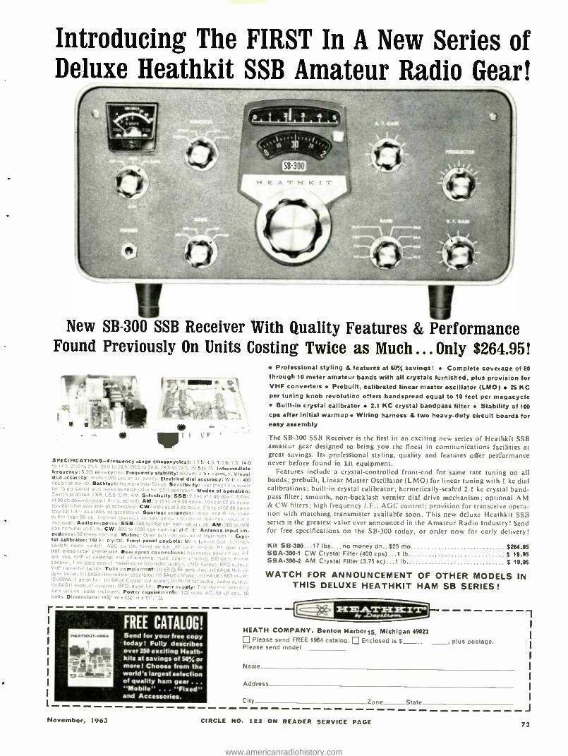
Introducing The FIRST In A New Series of Deluxe Heathkit SSB Amateur Radio Gear!
New SB -300 SSB Receiver With Quality Features & Performance Found Previously On Units Costing Twice as Much ... Only $264.95!
- a
SPECIFICATIONS- Frequency range (meo.rc ) 7 q 14 0
' 5 I" , 'B.S. 28.5 to 29., Intermediate frequency: .s. Fr st Visual dial accuracy::. .u0 cps on all band . 6 r 6 , o cps on all bands. Backlash: No more than 5e S e sit, . d ,. for 15 db signal plus noise- to.noise ratio for S Modes of operation: Switch selected: LSB, USB, CW, AM. Selectivity: SSB: 2.1 kc at 6 db down, 5.0 kc at 60 db down (crystal filler supplied). AM:3.75 kc at 6 db down. 10 kc at fA db down (crystal filter available as accessory. CW:400 cps at 6 db down. 2.5 kc at 60 db down (crystal filter available as accessory). Spurious response: lmaa. and IF rejection bettor than 50 db. Internal spurious signals below eguivair, nl antenna input of t microvolt. Audio response: SSB: 350 to 2450 cps nominal at 6 db. AM: 200 to 3500 cps nominal at 6 db. CW: 800 to 1200 cos nominal at 6 db. Antenna input Im- pedence: 50 ohms comma,. Muting: Orr n eternal ground at Mute socket. Crys- tal calibrator: 100 Ire cry, tai. Front panel controls: Main tuning dial. function switch: mode switch: AGC r. h.
r tch. AF gain control: RF pain con. trot: preselector; phone jack. Rear apron connections: Accessory power Nun. HF antenna: VHF 01 antenna: VHF r2 art - na: mut. spare: anti.trip: 500 ohm: 8 cnm speaker: line cord socket: heterodyne oscillator output: LMO output. BFO putout; VHF converter switch. Tube complement: (1) 6BZ6 RF amplifier: (1) 6AU6 Hi t. ro. dyne miner; (1) 6AB4 Heterodyne oscillator; (1) 6AU6 LM ose.: (1) 6AU6 LMO mirer: (2) 6BA6 IF amplifier: (1) 6AU6 Crystal calibrator; (1) 6HFB 1st audio, audio output: (1) 6AS11 Product detector. BFO, amplifier. Power supply: Trannlorn -. -r nr..nL I
with silicon diode rectifiers. Power requirements: 120 volts AC. 5' watts. Dimensions: 14j- W x H x 13.4 D.
r
NaaTSlltrT-1004
FREE CATALOG! Send for your free copy today ! Fully describes over 250 exciting Heath - kits at savings of 50% or more! Choose from the world's largest selection of quality ham gear ... "Mobile" ... "Fixed" and Accessories.
e Professional styling & features at 60% savings! Complete coverage of 80
through 10 meter amateur bands with all crystals furnished, plus provision for VHF converters Prebuilt, calibrated linear master oscillator (LMO) 25 KC per tuning knob revolution offers bandspread equal to 10 feet per megacycle
Built -in crystal calibrator 2.1 KC crystal bandpass filter Stability of 100
cps after initial warmup Wiring harness & two heavy-duty circuit boards for easy assembly
The SB -300 SSB Receiver is the first in an exciting new series of Heathkit SSB amateur gear designed to bring you the finest in communications facilities at great savings. Its professional styling, quality and features offer performance never before found in kit equipment.
Features include a crystal -controlled front -end for same rate tuning on all bands; prebuilt, Linear Master Oscillator (LMO) for linear tuning with I kc dial calibrations; built -in crystal calibrator; hermetically -sealed 2.1 kc crystal band - pass filter; smooth, non -backlash vernier dial drive mechanism; optional AM & CW filters; high frequency 1.F.: AGC control; provision for transceive opera- tion with matching transmitter available soon. This new deluxe Heathkit SSB series is the greatest value ever announced in the Amateur Radio Industry! Send for free specifications on the SB -300 today, or order now for early delivery!
Kit SB- 300...17 lbs.... no money dn., $25 mo. $264.95 SBA -300 -1 CW Crystal Filter (400 cps). .1 lb. $ 19.95 SBA -300 -2 AM Crystal Filter (3.75 Vic) _1 lb $ 19.95
WATCH FOR ANNOUNCEMENT OF OTHER MODELS IN THIS DELUXE HEATHKIT HAM SB SERIES !
HEATH COMPANY, Benton Harbor15 Michigan 49023 C] Please send FREE 1964 catalog. 12 Enclosed is $ Please send model
, plus postage.
Name
Address
City Zone State
November, 1963
J CIRCLE NO. 122 ON READER SERVICE PAGE 73
www.americanradiohistory.com
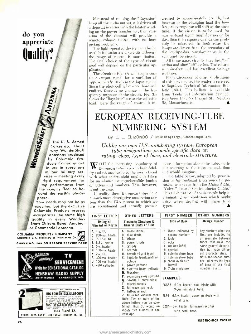
do you J
appreciate
Qualiti?
zQ y The U. S. Armed Forces do. That's
:24 why WonderShaft , antennas produced
Q by Columbia Pro- ducts Company are in use in every one of our military ser-
vices - meeting every rigid requirement for
top performance from the ocean's floor to be-
yond the earth's atmos- phere.
Your needs may not be as exacting, but the exclusive Columbia Products process incorporates the same high
quality in every Wonder - Shaft Citizens Band, Amateur or Commercial antenna.
COLUMBIA PRODUCTS COMPANY COLUMBIA S. C. Subsidiary of Shakespeare Co.
CIRCLE NO. 109 ON READER SERVICE PAGE
8AR6AIN TV ¡NNW
SERVICEMEN! Write for SENSATIONAL CATALOG
HENSHAW RADIO SUPPLY 3619 TROOST KANSAS CITY, MO.
Convert any telev,slon to senslove.
BIG -SCREEN OSCILLOSCOPE -., change -.
111 :.thott. t " N. ].. tronle -.0 ertenee n eded to 1.,
clearle. illustrated TECH. NICIANS. HAMS. EXPERIMENT- ERS. BROADCASTERS. U., ..hop, school. lah. An, ,tt -an
FULL PLANS S2.
RELCO, Dept. EW -11, Box 10563, Houston 18, Tex.
74
If instead of running the "Raysistor" lamp off the audio output, it is driven off a rheostat in series with the heater wind- ing on the power transformer, then vari- ation of the rheostat will provide a remote volume control with no hum pickup problems.
The light -operated device can also be used in transistor a.g.c. circuits although the range of control is more limited. The final choice of the type of circuit used will depend on the particular ap- plication.
The circuit in Fig. 3A will keep a con- stant output signal for a variation of approximately 10 db in the input signal. Since the photocell is between base and emitter, there is no change in the fre- quency response of the circuit. Fig. 3B shows the "Raysistor" across the collector load. Here the range of control is in-
creased to approximately 15 db, but because of the changing load the low - frequency response will shift at the same time. If the circuit is to be used for narrow -band signal amplification or for d.c., then this response change can prob- ably be tolerated. In both cases the lamps are driven from the secondary of the loudspeaker transformer as in the vacuum -tube circuit.
All these a.g.c. circuits have fast "on" action and slow "off" action. The control is noise -free and has excellent voltage isolation.
For a discussion of other applications of this new device, the reader is referred to Raytheon Technical Information Bul- letin 16:3 -1. This bulletin is available from Technical Information Service, Raytheon Co., 55 Chapel St., Newton 58, Massachusetts.
EUROPEAN RECEIVING -TUBE NUMBERING SYSTEM
By E. L. ELIZONDO / Senior Design Engr., Blonder- Tongue Labs.
Unlike our own U.S. numbering system, European tube designations provide specific data on
rating, class, type of base, and electrode structure.
ITH the increasing popularity of European tube types in high -fidel-
ity and r.f. applications, the user is faced with what at first sight might be taken for an almost incomprehensible jumble of letters and numbers. This, however, is not the case.
In reality, these European tubes have a much more descriptive numbering sys- tem than the EIA system to which we are accustomed and actually provide
more information about the tube, with- out resorting to the tube manual, than one would imagine.
The table below, adapted by permis- sion of International Electronics Corpo- ration, Kvas taken from the Dlullard Ltd. "Valve Tube and Semiconductor Cuide." This table can be of considerable help in eliminating any confusion which might arise when dealing with these tube types.
FIRST LETTER OTHER LETTERS FIRST NUMBER OTHER NUMBERS
Rating of Filament or Heater
Electrode Structure & General Class of Tube
Type of Base Design Number
A. 4 -v. N. C. 200 -ma. heater D..5.1.5 -v. fil. E. 6.3 -v. heater G. 5 -v. heater H. 150 -ma. heater K. 2 -v. fil. P. 300 -ma. heater U. 100 -ma. heater Z. cold cathode
A. single diode B. dual diode C. triode D. power triode E. tetrode F. pentode H. hexode 14 -grid type) K. heptode (pentagrid) or
octode L. power pentode M. electron beam indicator N. thyratron P. secondary emission tube Q. nonode (9 electrodes) T. miscellaneous X. full -wave gas rect. Y. half -wave rect. Z. full -wave vacuum rect. Note: Two or more of the above letters may be com-
bined. Thus CC would in-
dicate two triodes in one
envelope.
1. (base indicated by
second number) 2. loctal 3. octal 4. rimlock (B8A) 5. special 6. subminiature tube 7. subminiature tube 8. 9 -pin miniature
(novaD 9. 7 -pin miniature
Any numbers after the first are included to differentiate between tubes that have the same general descrip- tion but have differ - ent characteristics. Note: the second num- ber indicates the type of base if the first number is a 1.
EXAMPLES:
ECC83- 6.3 -v. heater. dual- triode with
9 -pin miniature base.
EL34- 6.3 -v. heater. power pentode with
octal base.
GZ34 -5 -v. heater. full -wave rectifier
with octal base.
ELECTRONICS WORLD
www.americanradiohistory.com
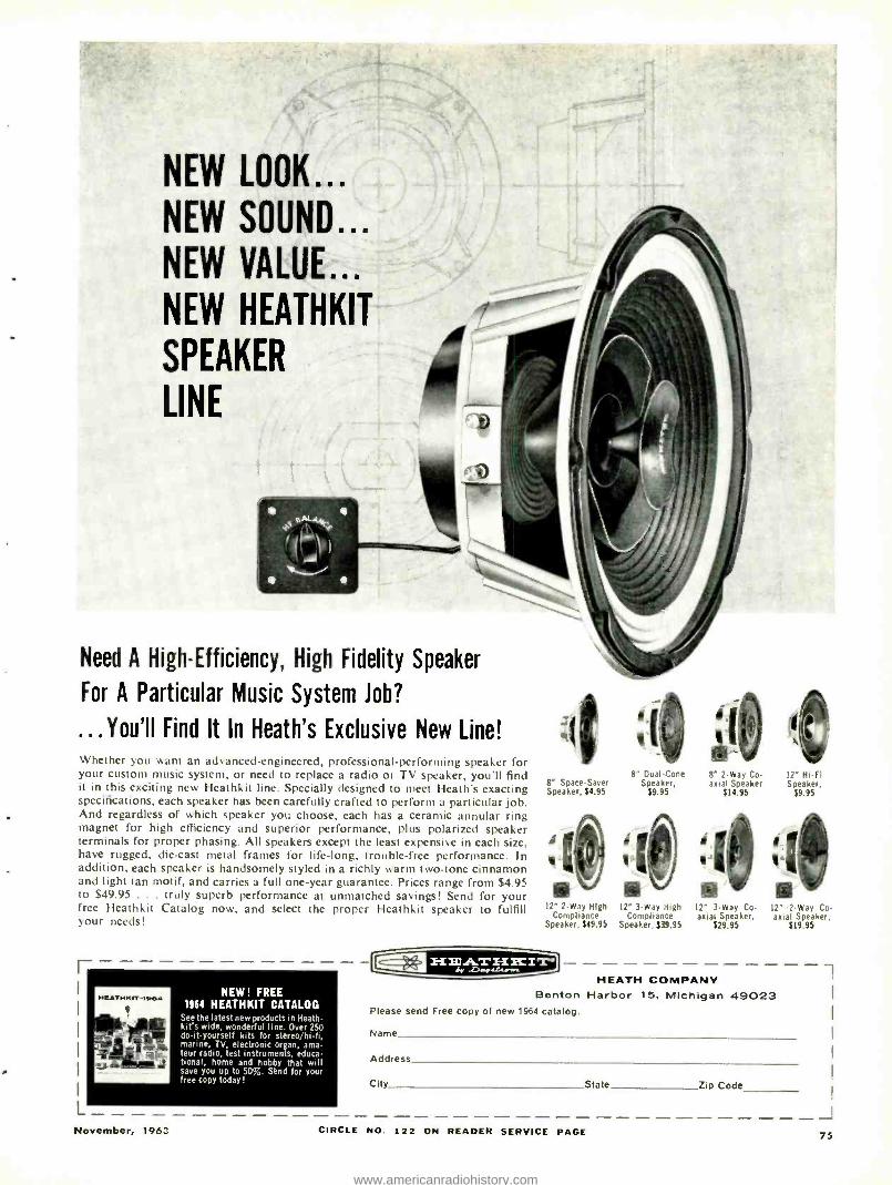
NEW LOOK...
NEW SOUND...
NEW VALUE...
NEW HEATHKIT
SPEAKER
LINE
Need A High- Efficiency, High Fidelity Speaker
For A Particular Music System Job?
...You'll Find lt In Heath's Exclusive New Line! Whether you want an advanced- engineered, professional -performing speaker for your custom music system, or need to replace a radio or TV speaker, you'll find it in this exciting new Heathkit line. Specially designed to meet Heath's exacting specifications, each speaker has been carefully crafted to perform a particular job. And regardless of which speaker you choose, each has a ceramic annular ring magnet for high efficiency and superior performance, plus polarized speaker terminals for proper phasing. All speakers except the least expensive in each size, have rugged, die -cast metal frames for life -long, trouble -free performance. In addition, each speaker is handsomely styled in a richly warm two -tone cinnamon and light tan motif, and carries a full one -year guarantee. Prices range from $4.95 to $49.95 ... truly superb performance at unmatched savings! Send for your free Heathkit Catalog now, and select the proper Heathkit speaker to fulfill your needs!
NEW! FREE 1964 HEATHKIT CATALOG
See the latest new products in Heath -
kit's wide, wonderful line. Over 250 do -it- yourself kits for stereo /hi -fi, marine, TV, electronic organ, ama- teur radio, test instruments, educa- tional, home and hobby that will save you up to 50 %. Send for your free copy today!
8" Space -Saver Speaker, =1.95
8" Duat -Cone Speaker,
$9.95
8' 2 -Way Co anal Speaker
$14.95
12" Hi-Fi Speaker,
$9.95
12" 2 -Way High 12" 3 -Way High 12" 3 -Way Co- 12' 2 -Way Co- Compliance Compliance axial Speaker, axial Speaker,
Speaker, $49.95 Speaker. 539.95 $29.95 $19.95 C riJ3ìATriKIT° 1 HEATH COMPANY
Benton Harbor 15, Michigan 49023 Please send Free copy of new 1964 catalog.
Name
Address
City State Zip Code
L J November, 1963 CIRCLE NO. 122 ON READER SERVICE PAGE 75
www.americanradiohistory.com
RADIO HANDBOOK the comprehensive reference source a problem solver for designers and builders of radio equipment
Gives simplified theory on practically every phase of radio. Tells how to design, build, and operate the latest standard types of radio transmitting and receiving equipment. More "How -To- Build" articles than any book in the field.
All information is original, up -to -date, and complete. 800 pages of data, clearly indexed, between hard covers -the largest RADIO HANDBOOK ever published.
Book #166
$9.50 (foreign $10.50) Order from your favorite electronic parts distributor.
If he cannot supply, send us his name and your remittance, and we will supply.
EDITORS and ENGINEERS, Ltd. Summerland 2, California 93067
Dealers: Electronic distributors, order from us. Bookstores. libraries. newsdealers order from Baker & Taylor, Hillside. N. J. Export (exc. Canada), order from H. J. Snyder Co., 440 Park Ave. So.. N.Y. 16.
CIRCLE NO. 115 ON READER SERVICE PAGE
ADVANCE ELECTRONICS SILICON CONTROLLED
PRV 7 AMP 25 AMP 70 1.75 3.00
140 2.25 3.50 200 2.50 3.75 250 3.00 4.00 300 3.35 4.35
RECTIFIERS TESTED! PRV 7 AMP 25 AMP 350 3.75 4.65 400 4.25 4.95 450 4.65 5.35 SOO 5.10 5.60 600 5.95 6.25
NPN- Germanium MESA Transistors F max -250 MC -BV -10V 10 5.00 100'41.50 Mixed Tra:sistors 10/1.00 MADT Transistors /1.00 Germanium Diodes Computer type -S /1.00 UHF Diode IN82A -L13128 10/2.50
VARIACS í1a AMP 6 25 110 AMP 18.95 2 AMP 7 49 20 AMP 24.95
ESTERLINE -ANGUS RECORDER Model ,g. AW 1 Ma Excellent Cond. W /Pen; ink; paper. tc. $229.50
VARIAN FOCUS MAGNETS =1504-A New 51195.00 Pair
CAPACITOR 1 Mfd. 12. 58 Volts OIL 514.95 ea.
TRANSFORMERS Pri 115 V or 230 V Sec. 3 x 6.3 V h 8 A. Ea. 230 V 0' 450 Ma Epoxy Encapsulated.. .56.95 ea. pri 115 V Sec 12.6 VCT (a 4 A 8 15 V V 1 A ............ .............. ... 2.95 ea. Stancor = PM8418 460 VCT p 50 Ma 8 6.3 V h 2.5 A 2 95 ea. 115 V Pri Sec. 6.3 VCT 6 30 Amp 6.95 ea.
PANEL 4" SQUARE
AC- VOLTS -0.2: 3; 5 10; 15; 25: 50 .3.95 ea. 0.712 8 15 5.95 ea.
AMPS- 0.1: 2: 3 5.95 V.
DC -MA- 0.50; 100 5.95 ea.
VOLTS -300; 500: 600 5 95 ea.
4" ROUND AC- VOLTS-
0 -50 3 50 ea. MA -0.150 ..3.50 ea.
DC- VOLTS -0.25; 300: 500 3 SO ea.
METERS 3" RD -AC
0.100 MA 2 95 ea. 0.130 VOLTS ..3.95 ea. 0.5 AMPS (marked 150
Ai 3 95 ea. 3" RD -DC
0.150 V & 300 V (Dual Seale) Weston 5.25 ea.
3" SQ. -DC 0 -5 MA 3 95 ea.
3" RD -DC 0.150: 200:
250 MA 4.25 ea. 0.20 MMA Weston 5.25 ea. 10 -0.6+ DB ...4.50 ea.
2' RD -DC 0 -1 MA 3.95 ea.
111 50. -OC 0 -1 MA ....3.75 ea. 0.100 MMA 3.95 ea.
NJE Adj Regulated POWER SUPPLY has 2 meters - 100.200 V tt' 100 Ma. or 200.500 V V 100 Ma .. .... 24.95 ea.
DC- REGULATED POWER SUPPLY --Hi Quality! Input -105 -120 V AC 60 Cy -Out 250 V DC u 300 MA ±1 ;. full load Mounted on Relay Rack Panel 1991257 ................24.95 ea. 3 for 560.00. TRANSISTOR CHARACTERISTIC PLOTTERS- DISplays r12- e12 -r22. less Scope $99.50 ea. PLATE TSFMR. 1100 V CT. 01 250 MA, 115 V PRI $5.49 P.O.
BLOWER Squirrel Cage type -27 V DC or 30 V AC- Filtered. 7.000 RPM packed in reusable Can
$3.95 ea.
All Shipments FOB NYC
ADVANCE ELECTRONICS 79 (oitlondt St., New York 7, N.Y. RE 20270
CIRCLE NO. 100 ON READER SERVICE PAGE 76
RADIO
TV NEWS
AFTER many years of looking at in- dustry figures for the total sales of
TV sets and radios, large numbers be- come rather commonplace. Even after seeing the various models displayed in the local department stores, the number of sets on parade are soon forgotten.
Recently, we were checking over some releases issued by the EIA on the total number of sales of TV and radio sets. As sometimes happens, the infor- mation on the sheet suddenly became very realistic, and after looking at the various figures, we got to wondering where all the sets are going. These fig- ures include only U.S. -made items.
Distributors sold 541,810 TV sets to dealers in June, 1963 as compared with 378,215 the month before and 480,510 in June of last year. This year's cumu- lative sales through June stood at 2,956,- 808 while last year during the same period, sales stood at 2,724,038.
Radio sales by distributors in June soared to 811,923 from the 598,410 sold in May. Despite this sharp increase, it is still below the 1,040,598 turned over in June of last year. This year's six - month total was 3,935,670 which lagged well behind last year's tally of 4,800,574 for the same period.
Production of all- channel TV sets shot up to 107,500 units in June making the total June output of TV sets 665,004 compared with the 507,499 sets the month before, and 620,653 sold in June, 1962. The year -to -elate tallies were 3,459,921 through June of this year and :3,295,501 for the same period last year.
The total output of radios for the month of June, 1963 %vas 1,653,866. This fell short of the 1,721,873 produced in June, 1962. The cumulative radio out- put through June, 1963 was 8,585,238 against 9,264,445 produced during the first six months of last year.
According to these figures, it appears that our consumer electronics industry is healthy and will enjoy a good year. But, I still wonder, where are all those sets going?
Imports From Japan Up Exports of electronic products from
Japan to the U.S. totaled $159- million
'í. .o~i'¡¡ I ..ííi +j i I I A
in 1962, a 32% increase over the 1961 total, according to the U.S. Department of Commerce. Sales to the U.S. ac- counted for over half of the total Japan- ese electronics exports in 1962. Mean- while, U.S. exports of electronics prod- ucts to all countries registered a 22% gain to $747 -million in 1962.
Japanese exports of TV receivers and chassis to the U.S. totaled $9.2- million, more than five times the level of 1961. Exports of transistor radios continued to show the largest dollar increase, account- ing for more than 45% of the total elec- tronic export to the U.S. Exports of tube -type, and other radios declined.
A total of 162,000 Citizens Band tranceivers, valued at $3.1- million, was exported to the U.S. in 1962. It is re- ported that many small transistor radio manufacturers have switched to the pro- duction of CB equipment, primarily for export to the U.S.
Educational Microwaves A recent FCC roiling opened a band
of 30 channels in the 2500 -mc. range for instructional use and now permits all school buildings within a school dis- trict or on a college campus to be inter- connected with as many as ten closed - circuit channels.
According to Stanley Lapin of Adler Electronics Inc., teaching by TV will be- come as familiar as the use of textbooks by 1970, as a result of this new ruling. For the past year, his company has been operating an experimental on- the -air sys- tem in the Plainedge, N.Y., school dis- trict. Originating in the high school, the instructional programs are sent to seven other schools in the 10,000 -stu- dent district.
\ \'bile the cost of the 2500 -nie. system is dependent on many local factors, such as district size and terrain, number and location of schools, and number of chan- nels desired, a two- channel instructional system can be installed in a large city for $2.25 per pupil, while in smaller districts, initial costs may be higher.
Although the 2500 -mc. systems are designed to serve local districts, they can be interconnected with other sys- tems for exchange of programs.
ELECTRONICS WORLD
www.americanradiohistory.com
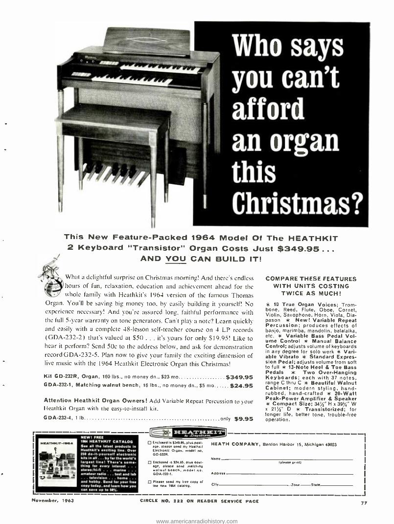
Who says you can't afford an organ this Christmas?
This New Feature -Packed 1964 Model Of The HEATHKIT 2 Keyboard "Transistor" Organ Costs Just $349.95...
AND YOU CAN BUILD IT!
What a delightful surprise on Christmas morning! And there's endless hours of fun, relaxation, education and achievement ahead for the whole family with Heathkit's 1964 version of the famous Thomas
Organ. You'll be saving big money too, by easily building it yourself! No experience necessary! And you're assured long, faithful performance with the full 5 -year warranty on tone generators. Can't play a note? Learn quickly and easily with a complete 48- lesson self- teacher course on 4 LP records (GDA -232 -2) that's valued at $50 ... it's yours for only $19.95! Like to hear it perform? Send 50e to the address below, and ask for demonstration record GDA- 232 -5. Plan now to give your family the exciting dimension of live music with the 1964 Heathkit Electronic Organ this Christmas!
Kit GD -232R, Organ, 160 lbs., no money dn., $23 mo $349.95 GDA- 232 -1, Matching walnut bench, 16 lbs., no money dn., $5 mo $24.95
Attention Heath kit Organ Owners! Add Variable Repeat Percussion to your Ieathkit Organ with the eas- to- inhtall kit.
GDA- 232 -4, 1 lb only $9.95
HEATHKIT-te564
Ewa.
J - e
NEW FREE 1164 HEATHKIT CATALOG See all the latest products in Heathkit's exciting line. Over 250 do -it- yourself electronic kits in all ... by far the world's largest line! There's some- thing for every interest . . .
stereo /hi -fi . . . marine . . .
amateur radio ... test and lab . television . . home . .
and hobby. Send for your Ire copy today, and learn how you can save up to 50%.
Enclosed is $349.95. plus post- age, please send my Heathhit Electronic Organ, model no. GD -232R.
D Enclosed is $24.95, plus post- age, please send matching walnut bench, model no. GOA- 232 -1.
D Please send my free copy of the new 1164 catalog.
COMPARE THESE FEATURES WITH UNITS COSTING
TWICE AS MUCH!
* 10 True Organ Voices; Trom- bone, Reed, Flute, Oboe, Cornet, Violin, Saxophone, Horn, Viola, Dia- pason * New! Variable Repeat Percussion; produces effects of banjo, marimba, mandolin, balalaika, etc. * Variable Bass Pedal Vol- ume Control * Manual Balance Control; adjusts volume of keyboards in any degree for solo work * Vari- able Vibrato * Standard Expres- sion Pedal; adjusts volume from soft to full * 13 -Note Heel & Toe Bass Pedals * Two Over -Hanging Keyboards; each with 37 notes, range C thru C * Beautiful Walnut Cabinet; modern styling, hand - rubbed, hand -crafted * 20 -Watt Peak -Power Amplifier & Speaker * Compact Size; 34%" H x 39%" W x 21112° D * Transistorized; for longer life, better tone, trouble -free operation.
HEATH COMPANY, Benton Harbor 15, Michigan 49023
Name - -- -
Address
City
(please print)
Zone State
J November, 1963 CIRCLE NO. 122 ON READER SERVICE PAGE 77
www.americanradiohistory.com
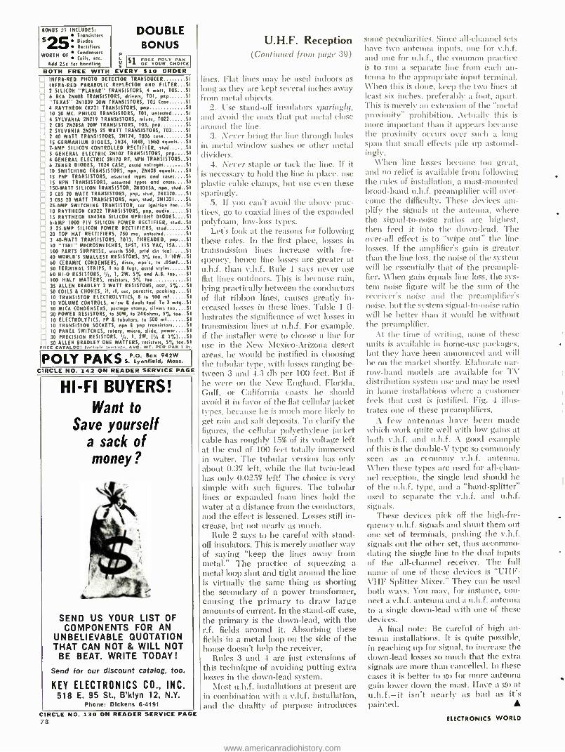
BONUS :1 INCLUDES: Transistors
$25 Diodes Rectifiers
WORTH OF Condensers Coils, etc.
Add 254 for handling
DOUBLE BONUS
P L $1 FREE POLY PAk
I a OF YOUR CHOICE
BOTH FREE WITH EVERY $10 ORDER INFRA -RED PHOTO DETECTOR TRANSDUCER S
INFRA -RED PARABOLIC REFLECTOR AND FILTER S
2 SILICON "PLANAR" TRANSISTORS, 4 watt, TOS 5
6 RCA 2N408 TRANSISTORS, drivers, TO1, pop S
"TEXAS" 2N1039 20W TRANSISTORS, TO5 Case S
4 RAYTHEON CK721 TRANSISTORS, pop S
,] 10 30 MC. PHILCO TRANSISTORS, TOI, untested $
i 4 SYLVANIA 2N219 TRANSISTORS, mixer, T022 S
J 2 CBS 2N2850 20W TRANSISTORS, T03, pop 5
2 SYLVANIA 2N296 25 WATT TRANSISTORS, T03 S
2 40 WATT TRANSISTORS, 2N174, T036 case S
IS GERMANIUM DIODES, 1N34, 1N48, 1N60 equals S
2 -AMP SILICON CONTROLLED RECTIFIER, stud S
S GENERAL ELECTRIC 2N107 TRANSISTORS, pnp 5 4 GENERAL ELECTRIC 2N170 RF, NPN TRANSISTORS 5
6 ZENER DIODES, T024 CASE, asstd voltages S
10 SWITCHING TRANSISTORS, npn, 2N43B equals 5
15 PNP TRANSISTORS, assorted types and cases 5 15 NPN TRANSISTORS, assorted types and cases. $
¡ 150 -WATT SILICON TRANSISTOR, 2N101SA, npn, stud S
.i 3 CBS 20 WATT TRANSISTORS, pnp, stud, 2N1320 5
3 CBS 20 WATT TRANSISTORS, npn, stud, 2N1321 5
25 -AMP SWITCHING TRANSISTOR, car ignition too 5 10 RAYTHEON 0722 TRANSISTORS, pop, audio S I 15 RAYTHEON IN434A SILICON UPRIGHT DIODES 5
6 -AMP 1000 PIV SILICON POWER RECTIFIER, stud 5
2 25 -AMP SILICON POWER RECTIFIERS, stud S
20 TOP HAT RECTIFIERS, 750 ma, untested S
3 40 -WATT TRANSISTORS, T013, THREADED, pnp 5
10 "TINT" MICROSWITCHES, SPST, 115 VAC, 15A 5
100 PARTS SURPRISE, worth SSO, prtd ckt tool S
40 WORLD'S SMALLEST RESISTORS, 5% too, 1'10W 51 60 CERAMIC CONDENSERS, discs, npo's, to .OSmf 5
50 TERMINAL STRIPS, 1 to 8 lugs, asstd styles S
60 HI -0 RESISTORS, ' /,, 1, 2W. 5% and A.B. tao 5 100 HALF WATTERS, resistors, S% too S
35 ALLEN BRADLEY 2 WATT RESISTORS, asst, S7, 5 SO COILS A CHOKES, if, rl, osc, parastic, peaking 5 10 TRANSISTOR ELECTROLYTICS, 8 to 100 sol S
10 VOLUME CONTROLS, w sw L duals too! To 3 meg S
SO MICA CONDENSERS, postage stamp, silvers too 5 30 POWER RESISTORS, to 50W, to 24Kohms, 5/ too 5
10 ELECTROLYTICS, FP L tubulars, to 500 mf S
10 TRANSISTOR SOCKETS, npn 8 pop transistors S
10 PANEL SWITCHES, rotary, micro, slide, power 5
30 PRECISION RESISTORS, I /,, I, 2W, Ph 8 1 %) Si 50 ALLEN BRADLEY ONE WATTERS, resistors, 5% too.S
FIlEF CATALOG' Ii, AVG. WT. PER PAR 1 la.
POLY PAKS P.0 942W 5. Lynn. ield, Mass.
CIRCLE NO. 142 ON READER SERVICE PAGE
HI -FI BUYERS! Want to
Save yourself a sack of money?
SEND US YOUR LIST OF COMPONENTS FOR AN
UNBELIEVABLE QUOTATION THAT CAN NOT & WILL NOT
BE BEAT. WRITE TODAY!
Send for our discount catalog, too.
KEY ELECTRONICS CO., INC. 518 E. 95 St., B'klyn 12, N.Y.
Phone: Dickens 6.4191
CIRCLE NO. 130 ON READER SERVICE PAGE 78
U.H.F. Reception (Continued from page :39)
lines. Flat lines may be used indoors as long as they are kept several inches away from metal objects.
2. Use stand -off insulators sparingly, and avoid the ones that put metal close around the line.
3. Never bring the line through holes in metal window sashes or other metal divide".
4. Never staple or tack the line. If it is necessary to hold the line in place. use plastic cable clamps, but use even these sparingly.
5. If you can't avoid the above prac- tices, go to coaxial lines of the expanded polyfoam, low -loss types.
Let's look at the reasons for following these rules. In the first place, losses in transmission lines increase with fre- quency, hence line losses are greater at u.h.f. than v.h.f. Rule 1 says never use flat lines outdoors. This is because rain, lying practically between the conductors of flat ribbon lines, causes greatly in- creased losses in these lines. Table 1 il- lustrates the significance of wet losses in transmission lines at u.h.f. For example, if the installer were to choose a line for use in the New Mexico- Arizona desert areas, he would be justified in choosing the tubular type, with losses ranging be- tween 3 and 4.3 (lb per 100 feet. But if he were on the New England, Florida, Gulf, or California coasts he should avoid it in favor of the flat cellular jacket types, because he is much more likely to get rain and salt deposits. To clarify the figures, the cellular polyethylene jacket cable has roughly 15% of its voltage left at the end of 100 feet totally immersed in water. The tubular version has only about 0.37 left, while the flat twin -lead has only 0.025% left! The choice is very simple with such figures. The tubular lines or expanded foam lines hold the water at a distance from the conductors, and the effect is lessened. Losses still in- crease, but not nearly as much.
Rule 2 says to be careful with stand- off insulators. This is merely another way of saying "keep the lines away from metal." The practice of squeezing a metal loop shut and tight around the line is virtually the same thing as shorting the secondary of a power transformer, causing the primary to draw large amounts of current. In the stand -off case, the primary is the down -lead, with the r.f. fields around it. Absorbing these fields ill a metal loop on the side of the house doesn't help the receiver.
Rules 3 and 4 are just extensions of this technique of avoiding putting extra losses in the clown -lead system.
Most u.h.f. installations at present are in combination with a v.h.f. installation, and the duality of purpose introduces
some peculiarities. Since all-channel sets have two antenna inputs, one for v.h.f. and one for u.h.f., the common practice is to run a separate line from each an- tenna to the appropriate input terminal. When this is clone, keep the two lines at least six inches, preferably a foot, apart. This is merely an extension of the "metal proximity" prohibition. Actually this is more important than it appears because the proximity occurs over such a long span that small effects pile up astound - ingly.
\ \'lien line losses become too great, and no relief is available from following the rules of installation, a mast -mounted broad -band u.h.f. preamplifier will over- come the difficulty. These devices am- plify the signals at the antenna, where the signal -to -noise ratios are highest, then feed it into the down -lead. The over -all effect is to "wipe out" the line losses. If the amplifier's gain is greater than the line loss, the noise of the system will be essentially that of the preampli- fier. \\'hen gain equals line loss, the sys- tem noise figure will be the sum of the receiver's noise and the preamplifier's noise, but the system signal-to-noise ratio will be better than it would be without the preamplifier.
At the time of writing, none of these units is available in home -use packages, but they have been announced and will be on the market shortly. Elaborate nar- row -band models are available for TV distribution system use and may be used in home installations where a customer feels that cost is justified. Fig. 4 illus- trates one of these preamplifiers.
A few antennas have been made which work quite well with low gains at both v.h.f. and u.h.f. A good example of this is the double -V type so commonly seen as an economy v.h.f. antenna. \ \'hen these types are used for all -chan- nel reception, the single lead should be of the u.h.f. type, and a "band- splitter" used to separate the v.h.f. and u.h.f. signals.
These devices pick off the high -fre- quency u.h.f. signals and shunt them out one set of terminals, pushing the v.h.f. signals out the other set, thus accommo- dating the single line to the dotal inputs of the all- channel receiver. The full name of one of these devices is "UHF - VHF Splitter Mixer." They can be used both ways. You may, for instance, con- nect a v.h.f. antenna and a u.h.f. antenna to a single down -lead vith one of these devices.
A final note: Be careful of high an- tenna installations. It is quite possible, in reaching up for signal, to increase the down -lead losses so much that the extra signals are more than cancelled. In these cases it is better to go for more antenna gain lower down the mast. Have a go at u.h.f. -it isn't nearly as bad as it's pained.
ELECTRONICS WORLD
www.americanradiohistory.com
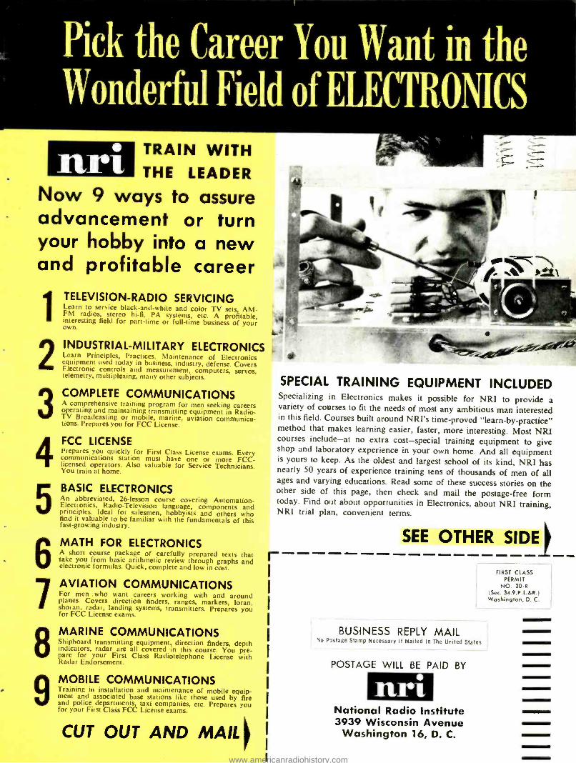
. T -.>
SPECIAL TRAINING EQUIPMENT INCLUDED Specializing in Electronics makes it possible for NRI to provide a variety of courses to fit the needs of most any ambitious man interested in this field. Courses built around NRI's time -proved "learn -by- practice" method that makes learning easier, faster, more interesting. Most NRI courses include -at no extra cost -special training equipment to give shop and laboratory experience in your own home. And all equipment is yours to keep. As the oldest and largest school of its kind, NRI has nearly 50 years of experience training tens of thousands of men of all ages and varying educations. Read some of these success stories on the other side of this page, then check and mail the postage -free form today. Find out about opportunities in Electronics, about NRI training, NRI trial plan, convenient terms.
r
Pick the Career You Want in the Wonderful Field of ELECTRONICS
uni TRAIN WITH THE LEADER
Now 9 ways to assure advancement or turn your hobby into a new and profitable career
1
2
3
4
5
6 7
8
9
TELEVISION -RADIO SERVICING Learn to service black- and -white and color TV sets, AM- FM radios, stereo hi -fi, PA systems, etc. A profitable, interesting field for part -time or full -time business of your own.
INDUSTRIAL -MILITARY ELECTRONICS Learn Principles, Practices, Maintenance of Electronics equipment used today in business, industry, defense. Covers Electronic controls and measurement, computers, servos, telemetry, multiplexing, many other subjects.
COMPLETE COMMUNICATIONS A comprehensive training program for men seeking careers operating and maintaining transmitting equipment in Radio - TV Broadcasting or mobile, marine, aviation communica- tions. Prepares you for FCC License.
FCC LICENSE Prepares you quickly for First Class License exams. Every communications station must have one or more FCC - licensed operators. Also valuable for Service Technicians. You train at home.
BASIC ELECTRONICS An abbreviated, 26- lesson course covering Automation - Electronics, Radio -Television language, components and principles. Ideal for salesmen, hobbyists and others who find it valuable to be familiar with the fundamentals of this fast -growing industry.
MATH FOR ELECTRONICS A short course package of carefully prepared texts that take you from basic arithmetic review through graphs and electronic formulas. Quick, complete and low in cost.
AVIATION COMMUNICATIONS For men who want careers working with and around planes. Covers direction finders, ranges, markers, loran, shoran, radar, landing systems, transmitters. Prepares you for FCC License exams.
MARINE COMMUNICATIONS shipbo:ud transmitting equipment, direction tinders, depth indicators, radar are all covered in this course. You pre- pare for your First Class Radiotelephone License with Radar Endorsement.
MOBILE COMMUNICATIONS framing in installation and maintenance of mobile equip- ment and associated base stations like those used by fire and police departments, taxi companies, etc. Prepares you for your First Class FCC License exams.
CUT OUT AND MAIL t
SEE OTHER SIDE
BUSINESS REPLY MAIL No Pastage Stamp Necessary If Mailed In The United States
POSTAGE WILL BE PAID BY
n,ri National Radio Institute 3939 Wisconsin Avenue Washington 16, D. C.
FIRST CLASS PERMIT
NO. 20 -R (Sec. 34.9, P. L.BR. ) Washington, D. C.
www.americanradiohistory.com
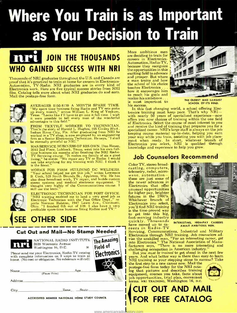
Where You Train is as Important as Your Decision to Train
n,ri JOIN THE THOUSANDS
WHO GAINED SUCCESS WITH NRI Thousands of NRI graduates throughout the U.S. and Canada are proof that it's practical to train at home for careers in Electronics - Automation, TV- Radio. NRI graduates are in every kind of Electronics work. Here are five typical success stories from NRI files. Catalog tells more about what NRI graduates do and earn. Mail the postage -free form.
'SEE
AVERAGES $150 -$170 A MONTH SPARE TIME. "My spare time business fixing Radio and TV sets picks up every month," writes William L. King of Yoakum, Texas. "Looks like I'll have to go into it full time. I wish it were possible to tell every man of the wonderful advantages in this field." FROM TEXTILE WORKER TO TECHNICIAN. That's the story of Harold L. Hughes, 225 Civiley Blvd., Indian River City, Fla. After graduating from NRI he worked in a TV shop, is now employed by an engineering firm as a Senior Electronics Technician. He says, "I shall be eternally grateful to NRI." HAS SERVICE BUSINESS OF HIS OWN. Don House, 3012 2nd Place, Lubbock, Texas, went into his own full - time business six months after finishing the NRI Radio - TV Servicing course. "It makes my family of six a good living," he states. "We repair any TV or Radio. I would not take anything for my training with NRI. I think it is the finest." WORKS FOR FIRM BUILDING DC WELDERS. "Your school helped me get this job," writes Lawrence S. Cook, 529 South Bounds St., Appleton, Wis. He has also done broadcast work, TV repair, and builds custom stereo systems and medical electronic equipment. "I thought very highly of the Communications course. I still use the texts." ELECTRONIC TECHNICIAN FOR POST OFFICE. "NRI training enabled me to land a very good job as Electronic Technician with the Post Office Dept.," re- ports Norman Ralston, 1947 Lawn Ave., Cincinnati, Ohio. "I finished 6th out of 139. I also have a very profitable spare -time business fixing Radios and TV."
OTHER SIDE
Cut Out and Mail -No Stamp Needed
nri NATIONAL RADIO INSTITUTE 3939 Wisconsin Avenue Washington 16, D.C. 3E
Please send me your Electronics, Radio -TV catalog with complete information on 9 ways to train at home. (No cost or obligation. No salesman will call )
Name Age (Please Print)
Address
City Zone _State_
The Amazing
Field of
Electronics
ACCREDITED MEMBER NATIONAL HOME STUDY COUNCIL
More ambitious men are deciding to train for careers in Electronics - Automation, Radio -TV, because they recognize the opportunities in this exciting field to advance and prosper. But where a man trains and how the school of his choice teaches Electronics . . .
how it encourages him to reach his goals and realize his ambitions .. .
is most important to his success.
In this fast changing world, a school offering Elec- tronics training must keep pace. That's why NRI- with nearly 50 years of specialized experience-now offers you nine choices of training within the one field of Electronics. Select the course of most interest to you and receive the kind of training that prepares you for a specialized career. NRI's large staff is always on the job keeping course material up -to -date, helping you earn your way while you train, assisting you with job place- ment when ready. In short, whatever branch of Electronics you select, NRI is qualified through knowledge and experience to help you grow.
.1
THE OLDEST AND LARGEST SCHOOL OF ITS KIND.
Job Counselors Recommend Color TV, stereo broad- casting, computers, telemetry, radar, micro- wave, automation - these are just some of the newer advances in Electronics that offer unusual opportunities for higher pay, brighter futures in the 1960's. Whichever branch of Electronics you select, you'll find NRI training is the time - proved way to get into this big, fast- moving industry quickly. Thousands have moved up to ca- reers in Radio -TV Servicing, Communications, Industrial and Military Electronics through NRI training. Job counselors ad- vise the unskilled man, "For an interesting career, get into Electronics." The National Association of Manu- facturers says, "There is no more interesting and challenging occupation in American industry."
But you must be trained to get ahead in the next few years. And what better way is there than easy -to -learn NRI training as your stepping stone to success? Take the first step to a new career now. Mail the postage -free form today for the NRI ceta- y`
log that pictures and describes training equipment, courses you take, facts about job opportunities, trial plan, convenient terms. NFU TRAINING, Washington 16, D.C. ""
INTERESTING, HIGH -PAY CAREERS AWAIT AMBITIOUS MEN.
\11>
ICUT OUT AND MAIL FOR FREE CATALOG
www.americanradiohistory.com
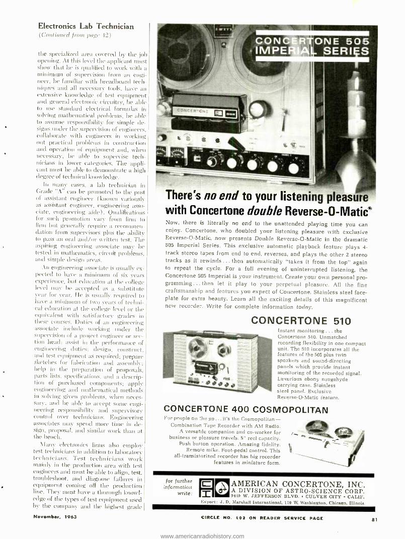
Electronics Lab Technician Continued from pa!» I2
the specialized area covered by the job opening. At this level the applicant must show that he is qualified to work with a minimum of supervision from an engi- neer, be familiar with breadboard tech- niques and all necessary tools, have an extensive knowledge of test equipment and general electronic circuitry, be able to use standard electrical formulas in solving mathematical problems, be able to assume responsibility for simple de- signs under the supervision of engineers, collaborate with engineers in working out practical problems in construction and operation of equipment and, when necessary, be able to supervise tech- nicians in lower categories. The appli- cant must be able to demonstrate a high detlrce of technical knowledge.
In many cases, a lab technician in Grade "A" can be promoted to the post of assistant engineer ( known variously as assistant engineer, engineering asso- ciate, engineering aide). Qualifications for such promotion vary from firm to firm but generally require a recommen- dation from supervisors plus the ability to pass an oral and /or written test. The aspiring engineering associate may be tested in mathematics, circuit problems, and simple design ;eras.
An engineering associate is usually ex- pected to have a minimum of six years experience, but education at the college level may be accepted as a substitute year for year. He is Usually required to have a minimum of two years of techni- cal education at the college level or the equivalent Nvith satisfactory grades in these courses. Duties of an engineering associate include working under the supervision of a proiect engineer or sec- tion head; assist in the performance of engineering duties; design, construct, and test equipment as required; prepare sketches for fabrication and assembly; help in the preparation of proposals, parts lists, specifications, and a descrip- tion of purchased components; apply engineering and mathematical methods in solving given problems, when neces- sary: and be able to accept some engi- neering responsibility and supervisory control over technicians. Engineering associates may spend more time in de- sign. proposal, and similar work than at the bench.
Many electronics firms also employ test technicians in addition to laboratory technicians. Test technicians work mainly in the production area with test engineers and must be able to align, test, troubleshoot, and diagnose failures in equipment coming off the production line. They must have a thorough knowl- edge of the types of test equipment used by the company and the highest grade
November, 1963
frml IR**11
_ ttttt.5.e..
There's no end to your listening pleasure with Concertone double Reverse- O- Maticf' Now, there is literally no end to the unattended playing time you can enjoy. Concertone, who doubled your listening pleasure with exclusive Reverse -O- Matic, now presents Double Reverse -O -Matic in the dramatic 505 Imperial Series. This exclusive automatic playback feature plays 4- track stereo tapes from end to end, reverses, and plays the other 2 stereo tracks as it rewinds ... then automatically "takes it from the top" again to repeat the cycle. For a full evening of uninterrupted listening, the Concertone 505 Imperial is your instrument. Create your own personal pro- gramming... then let it play to your perpetual pleasure. All the fine craftsmanship and features you expect of Concertone. Stainless steel face- plate for extra beauty. Learn all the exciting details of this magnificent new recorder. Write for complete information today.
CONCERTONE 510 Instant monitoring ... the Concertone 510. Unmatched recording flexibility in one compact unit. The 510 incorporales all the features of the 505 plus twin speakers and sound- directing panels which provide instant monitoring of the recorded signal. Luxurious ebony naugahyde carrying case. Stainless steel panel. Exclusive Reverse -O -Matie feature.
CONCERTONE 400 COSMOPOLITAN For people on the go... it's the Cosmopolitan -
Combination Tape Recorder with AM Radio. A versatile companion and co- worker for
business or pleasure travels. 5" reel capacity. Push button operation. Amazing fidelity.
Remote mike. Foot -pedal control. This all- transistorized recorder has big recorder
features in miniature form.
for further ;nfcrmation
write.
. t...
AMERICAN CONCERTONE, INC. A DIVISION OF ASTRO- SCIENCE CORP. 9449 W. JEFFERSON BLVD. CULVER CITY CALIF.
Exeort:.1. D. Marshall International, 170 W. Washington, Chicago, Illinois
CIRCLE NO. 102 ON READER SERVICE PAGE 81
www.americanradiohistory.com
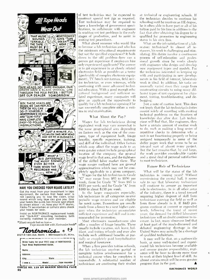
NI Tape heads
Wear Out THAT MUSIC)
SOUNDS TERRIBLE. f0 " THE TAPE K. - MUST BE WORN OUT
NORTRON /CS SAYS "TAPE DOESN'T WEAR OUT ---
SPOT CHECK HEADS IN
2 MINUTES ...Look for A. Crookes or
spots on
_r B. Thin dace.
- eerti VV cal black
line d'ale either
mas plea. Peur, TAPE HEADS DO! SURE ENOUGH, OUR HEADS HAVE A BLACK VERTICAL LINE THROUGH THE POLE PIECES. I BETTER SEE OUR DEALER J
BOY, THESE HEADS ARE 'moi WORN. WE CAN REPU -a 5
OR YOU CAN DOIT -OURSELF. '
HEADS r ,. ANO "QUIK -KITS" r
HAVE COMPLETE
N-70i) EASY-TO-FOLLOW INSTRUCTIONS.
ts_ tad JUST A MINUTE, I'LL
9 ` /AZIMUTH THIS NEW HEAD AND WE'RE IN BUSINESS.
-/ NEW.
WHAT A BI G DIFFERENCE.
THE MUSIC SOUNDS EVEN BETTER THAN WHEN THE RECORDER WAS
HAVE YOU CHECKED YOUR HEADS LATELY?
Get the most from your investment in tape equipment. Be certain that head wear is not causing you to lose the clean, crisp sound which only tape can give you. Give your heads the quick two minute spot check as shown above - or, have your Hi -Fi dealer, Radio -TV serviceman or camera store check your heads for wear.
Insist on NORTRONICS replacement heads and "Quik -Kit" mounting hardware; both correctly matched to your recorder.
"Music sounds best on tape - Tape sounds best with Nortronics heads"
-71.00L#hosúca._ l 8127 -D 10th Ave. North Minneapolis 27, Minn.
r 1 Write today for your FREE copy of NORTRONICS
Tape Head Replacement Guide.
Name
Address
Cty State
LI own a Model tape recorder,
CIRCLE NO. 139 ON READER SERVICE PAGE 82
of test technician nary be expected to construct special test jigs as required. Test technicians may be required to have a knowledge of government speci- fications, to collaborate with engineers in working out test problems in the early stages of production, and to assist in writing test procedures.
\ \'hat about someone who would like to become a lab technician and who has the minimum educational requirements but not the specified experience? It boils down to the old problem -how can a person get experience if employers hire only experienced applicants? The answer is to get experience in as closely related electronics fields as possible -as a tester (preferably of complex electronic equip- ment ) , TV bench serviceman, field serv- ice technician, or even \yireman, while continuing with more advanced techni- cal education. With a good enough edu- cational background and sufficient re- lated experience, many companies will give an applicant the opportunity to qualify for a lab technician opening if he can successfully complete either a writ- ten or oral examination.
What About the Pay? Wages for lab technicians doing
equivalent work may vary somewhat in the same geographical area depending on factors such as the size of the com- pany, type of equipment built, fringe benefits, specific experience, training, and skill of the individual. Other factors which may affect the wage scale to an even greater extent include geographical location of the company, the general wage level in that area, and the tightness of the skilled labor market there. The wage ranges outlined here are general approximations which may not be corn - pletely applicable to a given company.
Wages for the lab technician in Grade "C" may range from $65 to $100 per week; those for Grade "B" from $85 to $125 per week; and for Grade "A" from $100 to about $150 per week.
In the larger companies especially, lab technicians in all categories receive periodic wage reviews and are eligible for merit raises. Promotions are usually made from a lower to a next higher cate- gory when the technician accumulates sufficient experience and skill and is rec- ommended for promotion.
Most electronics manufacturers also offer a number of fringe benefits. These usually include vacation, sick leave, hol- idays, and tuition refunds and may also include such additional benefits as par- tially or completely paid hospitalization and surgical insurance.
When a firm provides tuition refunds, the lab technician receives partial or complete tuition reimbursement for a technical course when he completes it successfully. A substantial number of technicians are continuing their studies
at technical or engineering schools. If the technician decides to continue his schooling until he receives an EE degree, he is often able to have part or all of his tuition paid by his firm in addition to the fact that after obtaining his degree he is qualified for promotion to engineering status in his own firm.
\ \'hat are the job satisfactions of a lab- oratory technician? In almost all in- stances, his work is challenging and stim- ulating. His duties involve a continuons process of self -education and profes- sional growth since he works closely with engineers who design and develop new equipment types and models. For the technician interested in keeping up with and participating in new develop- ments in his field of interest, laboratory work is ideal. In addition, his tasks are unusually varied since they range from constructing circuits to using many dif- ferent types of test equipment for align- ment, testing, troubleshooting, and de- bugging.
Just a note of caution here. This sloes not imply that the lab technician's duties consist solely of wrestling with exciting technical problems on the frontiers of knowledge day after day. Lab techni- cians will find that, like engineers, they have a certain amount of routine work to do, such as making a long series of repetitive checks to determine why a unit is not functioning properly or being assigned temporarily to some of the duller paper work that seems to be an integral part of almost every project. But the fact remains that, by and large, the \vork provides considerable variety and a great deal of personal satisfaction to most technicians.
Future Role of Technicians \ \'hat will be the status of the lab
technician in coming years? Without overstraining the crystal ball, it seems safe to say that laboratory technicians will continue to assume an important role in electronics. As in all other areas of the industry, there is a trend toward requiring higher degrees of skill from technicians entering the field as well as from those already in it. If R &D pro- grams continue at current or expanded levels, following the trend of recent years, the demand for skilled laboratory technicians will no doubt continue to in- crease. In fact, many observers feel that at least part of the much -discussed and debated engineering shortage in the United States may actually be a shortage of qualified technicians.
It may well be that, on a nationwide basis, as more well -trained and experi- enced lab technicians become available and assume greater responsibility, engi- neers will be freer to devote more time to work at their highest level of skill. An almost certain result will be even greater progress than in the past.
ELECTRONICS WORLD
www.americanradiohistory.com
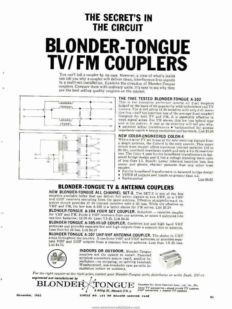
THE SECRET'S IN THE CIRCUIT
BLONDER -TONGUE TV/ FM COUPLERS
You can't tell a coupler by its case. However, a view of what's inside can tell you why a coupler will deliver clean, interference -free signals to a multi -set installation. Examine the circuitry of Blonder- Tongue couplers. Compare them with ordinary units. It's easy to see why they are the best selling quality couplers on the market.
THE TIME TESTED BLONDER -TONGUE A -102 This is the champion performer among all 2 -set couplers judged on the basis of its popularity with technicians and TV viewers. The A -102 offers 12 db isolation with only 3 db inser- tion loss -half the insertion loss of the average 2 -set coupler! Designed for both TV and FM, it is especially effective in weak signal areas. For FM stereo, this low loss hybrid type unit is the answer. A look at its circuitry will tell you why.
patented bifilar transformers backmatched for precise impedance match heavy conductors end burnouts. List $3.20 NEW COLOR- ENGINEERED COLOR -4 Where a color TV set is one of the sets receiving signals from a single antenna, the Color -4 is the only answer. This super deluxe 4 -set coupler offers maximum interset isolation (16 to 24 db), excellent impedance match and only a 6.5 db insertion loss. The Color -4 uses ferrite broadband transformers in bal- anced bridge design and it has a voltage standing wave ratio of less than 1.5. Result: Lower inherent insertion loss, less smear and ghosts, sharper pictures than any other 4 -set coupler.
Ferrite broadband transformers in balanced bridge design VSWR of outputs and inputs no greater than 1.5. Backmatched List $9.95
o
o
Q9 QQSl9
Täîf2fn7S1 J ° -/fbób -o
BLONDER -TONGUE TV & ANTENNA COUPLERS NEW BLONDER- TONGUE ALL CHANNEL SET -2. The SET -2 is one of the few couplers available today that can deliver full power signals to two UHF, or a VHF and UHF receivers operating from the same antenna. Effective straightforward re- sistive circuit provides 12 db interset isolation with 6 db loss. While it's effective on VHF and FM, the low loss A -102 is a better choice for FM stereo. List $3.20 BLONDER -TONGUE A -104 FOUR SET COUPLER. Inductive - resistive coupler for VHF and FM. Feeds 4 VHF receivers from one antenna, or mixes 4 antennas into one line. Isolation: 12 -20 db. Loss: 7.5 db. List $4.50 BLONDER -TONGUE A- 105 -HI -LO COUPLER. Combines low and high band VHF antennas and provides separate low and high outputs from a common line or antenna. Less than 0.5 db loss. List $4.10 BLONDER -TONGUE A -107 UHF -VHF ANTENNA COUPLER. The choice in UHF areas throughout the country. It combines VHF and U HI antennas, or provides sepa- rate VHF and UHF outputs from a common line or antenna. Less than 1.0 db loss. List $4.75
INDOORS OR OUTDOOR. Blonder- Tongue couplers are the easiest to install. Patented stripless connectors assure rapid, positive in- stallation-no stripping, no splicing twinlead. Weatherproof, non -breakable case permits in- stallation indoor or outdoors.
For the right coupler at the right price, contact your Blonder -Tongue parts distributor or write Dept. EWV engineered and manufactured by 1
BLONDER TONGUE November, 1963
9 Ailing SL, Newark. 2 N. J.
Canadian Div. Benco Television Assoc., Ltd Tor., Ont, hone TV accessories closed circuit TV systems UHF converters master TV systems
CIRCLE NO. 165 ON READER SERVICE PAGE 83
www.americanradiohistory.com
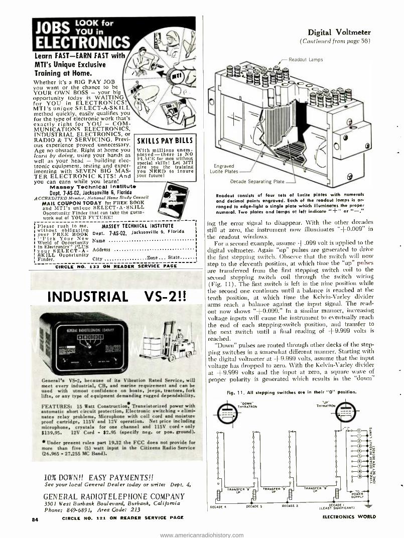
JOBSLOOK for
YOU in
ELECTRONICS Learn FAST -EARN FAST with MTI's Unique Exclusive Training at Home. Whether its a BIG PAY JOB you want or the chance to be YOUR OWN BOSS - your big opportunity today is WAITING for YOU in ELECTRONICS! MTI's unique SELECT -A -SKILL method quickly, easily qualifies you for the type of electronic work that's exactly right for YOU - COM- MUNICATIONS ELECTRONICS, INDUSTRIAL ELECTRONICS. or RADIO & TV SERVICING. Previ- ous experience proved unnecessary. Age no obstacle. Right at home you learn by doing, using your hands as well as your head - building elec- tronic equipment. testing and exper- imenting with SEVEN BIG MAS- TER ELECTRONIC KITS! And you can earn while you learn!
Massey Technical Institute Dept. 7- AS -02, Jacksonville 6, Florida
ACCREDITED M. reeler. Nntionnt Home Study Council MAIL COUPON TODAY for FREE BOOK and MTI's unique SELECT -A -SKILL Opportunity Finder that can take the guess- work out of YOUR FUTURE!
SKILLS PAY BILLS With millions unem- ployed -there is NO PLACE for men without special skills! Let MTI give you the training you NEED to insure your future!
Please rush to me. without obligation your FREE BOOK 'Pick Your New
World of Opportunity in Electronics' PLUS your SELECT -A- SKILL Opportunity Finder.
MASSEY TECHNICAL INSTITUTE
Dept. 7-AS-02, Jacksonville 6, Florida
Name
Address
City Zone . State
CIRCLE NO. 133 ON READER SERVICE PAGE
INDUSTRIAL VS -2!!
, Lm,. - -f!
, 1 General's VS -2, because of its Vibration Rated Service, will meet every industrial, CB, and marine requirement and can be used with utmost confidence on boats, jeeps, tractors, fork lifts, or any type of equipment demanding rugged dependability.
FEATURES: 15 Watt automatic short circuit nates relay problems, proof cartridge, 115V microphone, crystals $139.95. 12V Cord
Construction, Transistorized power with protection, Electronic switching - elimi- Microphone with coil cord and moisture
and 12V operation. Net price including for one channel and 115V cord - only
$2.95 (specify neg. or pos. ground).
*Under present rules part 19.32 the FCC does not provide for more than five (5) watt input in the Citizens Radio Service (26.965 - 27.255 MC Band).
84
10% DOWN!! EASY PAYMENTS!! See your local General Dealer today or write: Dept. 4,
GENERAL RADIOTELEPHONE COMPANY 3501 West Burbank Boulevard, Burbank, California Phone: 849.6891, Area Code: 213
CIRCLE NO. 121 ON READER SERVICE PAGE
Digital Voltmeter (Continued from page 56)
Readout Lamps
Engraved Lucite Plates
Decade Separating Plate
Readout consists of four sets of Lucite plates with numerals and decimal points engraved. Each of the readout lamps is ar- ranged to edge -light a single plate which illuminates the proper numeral. Two plates and lamps at left indicate " +" or " -."
ing the error signal to disappear. With the other decades still at zero, the instrument now illuminates "+0.009" in the readout windows.
For a second example, assume +.099 volt is applied to the digital voltmeter. Again "up" pulses are generated to drive the first stepping switch. Observe that the switch will now step to the eleventh position, at which time the "up" pulses are transferred from the first stepping switch coil to the second stepping switch coil through the switch wiring ( Fig. 11) . The first switch is left in the nine position while the second one continues until a balance is reached at the tenth position, at which time the Kelvin -Varley divider arms reach a balance against the input signal. The read- out now shows " +0.099." In a similar manner, increasing voltage inputs will cause the instrument to eventually reach the end of each stepping- switch position, and transfer to
the next switch until a final reading of +9.999 volts is
reached. "Down" pulses are routed through other decks of the step-
ping switches in a somewhat different manner. Starting with the digital voltmeter at +9.999 volts, assume that the input voltage has dropped to zero. With the Kelvin -Varley divider at +9.999 volts and the input at zero, a square wave of proper polarity is generated which results in the "down"
Fig. 11. All stepping switches ara in their "0" position.
oowN' u TnYRATRON THrRn'RON
P
0
0--.
o
o
o
o
o
O
o
TRANSFER 9 UP
TRANSFER 9 UP
TRANSFER -9 UP
DECADE 4 DECADE 3
POWER SUPPLY
DECADE 2 DECADE I
I LE AST SIGNIFICANTI
ELECTRONICS WORLD
www.americanradiohistory.com
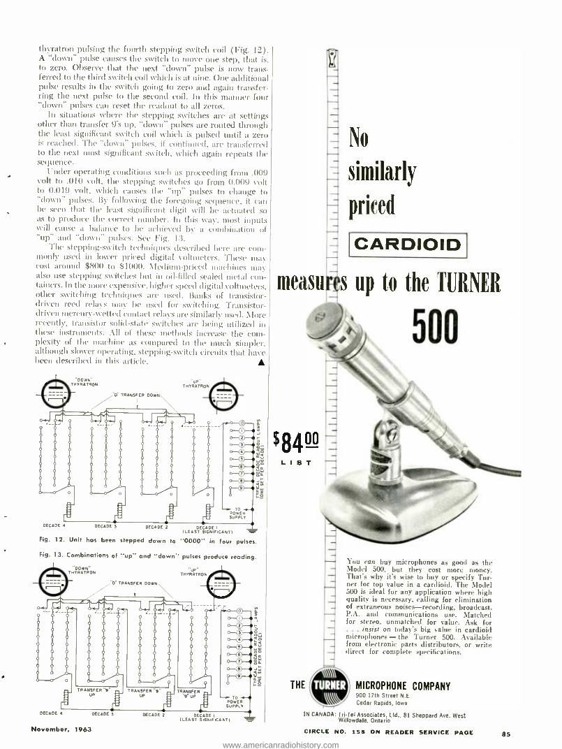
thyratron pulsing the fourth stepping switch coil (Fig. 12) .
A "down" pulse causes the switch to move one step, that is, to zero. Observe that the next "down" pulse is now trans- ferred to the third switch coil which is at nine. One additional pulse results in the switch going to zero and again transfer- ring the next pulse to the second coil. In this manner four "down" pulses can reset the readout to all zeros.
In situations where the stepping switches are at settings other than transfer 9's up, "down" pulses are routed through the least significant switch coil which is pulsed until a zero is reached. The "down" pulses, if continued, are transferred to the next most significant switch, which again repeats the sequence.
Under operating conditions such as proceeding from .009 volt to .010 volt, the stepping switches go from 0.009 volt to 0.019 volt, which causes the "up" pulses to change to "down" pulses. By following the foregoing sequence, it can be seen that the least significant digit will be actuated so as to produce the correct number. In this way, most inputs will cause a balance to he achieved by a combination of "up" and "clown" pulses. See Fig. 13.
The stepping- switch techniques described here are com- monly used in lower priced digital voltmeters. These may cost around $800 to $1000. Medium- priced machines may also use stepping switches but in Oil -filled sealed metal con- tainers. In the more expensive, higher speed digital voltmeters, other switching techniques are used. Banks of transistor - driven reed relays may be used for switching. Transistor - driven mercury- wetted contact relays are similarly used. More recently, transistor solid -state switches are being utilized in these instruments. All of these methods increase the com- plexity of the machine as compared to the much simpler, although slower operating, stepping -switch circuits that have been described in this article.
"DOWN" THYRATRON
% O" TRANSFER DOWN.
No
similarly
priced
CARDIOID
measures up to the TURNER
500
DECADE it it
DECADE 3 DECADE 2 DECADE I
(LEAST SIGNIFICANT)
Fig. 12. Unit has been stepped down to "0000" in four pulses.
- POWER
SUPPLY
Fig. 13. Combinations of "up" and "down" pulses produce reading.
"DOWN" THYRATRON THYRATRD',
O TRANSFER DOWN
TRANSFER "9" TRANSFER "9 UP : uP
RAN._J 9' UP - -r TO
POWER SUPPLY
DECADE 4 DECADE 3
November, 1963
DECADE 2 DECADE (LEAST SIGNIFICANT)
THE
You can buy microphones as good as the Model 500, but they cost more money. That's why it's wise to buy or specify Tur- ner for top value in a cardioid. The Model 500 is ideal for any application where high quality is necessary, calling for elimination of extraneous noises -recording, broadcast, P.A. and communications use. Matched for stereo, unmatched for value. Ask for
. insist on today's big value in cardioid microphones -the Turner 500. Available from electronic parts distributors, or write direct for complete specifications.
MICROPHONE COMPANY 900 17th Street N F.
Cedar Rapids, Iowa
IN CANADA: TriTel Associates, Ltd., 81 Sheppard Ave. West Willowdale, Ontario
CIRCLE NO. 158 ON READER SERVICE PAGE 85
www.americanradiohistory.com
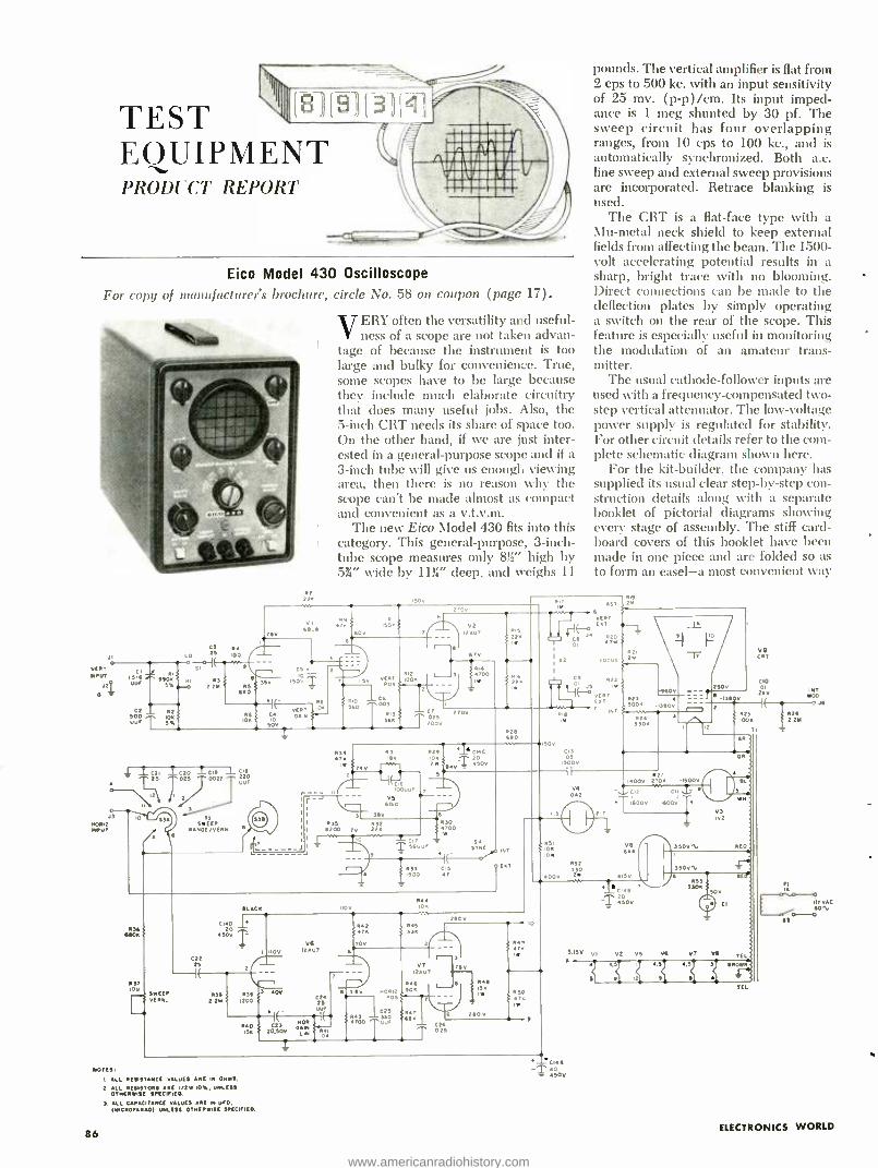
TEST EQUIPMENT PRODUCT REPORT
[18 E91 ] (4T
r...`-Di, Eico Model 430 Oscilloscope
For copy of manufacturer's brochure, circle No. 58 on coupon
CI I a-6 UuF
C3
LO =S
e-i RI¡
ff05. NI R3 5xe.-D 2 21
0-4 Cz R2.
50o Io5 , UM, T ax
P. 100
(page 17).
VERY often the versatility and useful- ness of a scope are not taken advan-
tage of because the instrument is too large and bulky for convenience. True, some scopes have to be large because they include much elaborate circuitry that does many useful jobs. Also, the 5 -inch CRT needs its share of space too. On the other hand, if we are just inter- ested in a general- purpose scope and if a 3 -inch tube will give us enough viewing area, then there is no reason why the scope can't be made almost as compact and convenient as a v.t.v.m.
The new Eico Model 430 fits into this category. This general- purpose, 3 -inch- tube scope measures only 8' J high by 5%" wide by 11g" deep, and weighs 11
3 5
V 150 0 -T
t 0Sa 3a
Sao
IO 50V
4, iczl ÌC20 ÌC1! 1 c16
2a OOZZ ^ uus
55 SWEEP
RINGE /VENN
S3A
150V
150. 6
aV FM 012
I 100
_2
0 C6 .003
+III 513 Jr
56R 25
T20'
R3 531 71t IRK
3 540
2,0
V2 12U2
ST
RI ; T00 IW
27OV
o zo
V 500
M15
225
H ( R16 y 225
R2S 660
C16 0000. ,
VO 6010
I 035 R32 I 6200 22.
I 4 I
CIT ic56UU
50
Rit
pounds. The vertical amplifier is flat from 2 cps to 500 kc. with an input sensitivity of 25 mv. (p -p) /cm. Its input imped- ance is 1 meg shunted by 30 pf. The sweep circuit has four overlapping ranges, from 10 cps to 100 kc., and is automatically synchronized. Both a.c. line sweep and external sweep provisions are incorporated. Retrace blanking is used.
The CRT is a flat -face type with a Mu -metal neck shield to keep external fields from affecting the beam. The 1500 - volt accelerating potential results in a sharp, bright trace with no blooming. Direct connections can be made to the deflection plates by simply operating a switch on the rear of the scope. This feature is especially useful in monitoring the modulation of an amateur trans- mitter.
The usual cathode -follower inputs are used with a frequency -compensated two - step vertical attenuator. The low -voltage power supply is regulated for stability. For other circuit details refer to the com- plete schematic diagram shown here.
For the kit- builder, the company has supplied its usual clear step -by -step con- struction details along with a separate booklet of pictorial diagrams showing every stage of assembly. The stiff card- board covers of this booklet have been made in one piece and are folded so as to form an easel -a most convenient way
150V
C13 05
IS00V
530 700 IW
034 0405
c2z 25
P37
VWEE ERN.
MACK
c16D 20
450v
R36 f 2Ir 3 Iz0N50
1 110 V6
12 AV7
4,4 065
f 33.
OÑ
3 40v 6 3 f v 00012 C24 1~- 05 25
lf »iE- C23
LIM
Z
250V
1
524 3
3305
V. 002
PSI 105 IOW
052
000
r-3 v7
12Ú7
5.6 !O5
TOO
`! Ru 55 IW
043 ú0 £sé. ., 0 E C26 T 025
240V
04.
050
NOTES
I. ALL RESISTANCE VALUES ARE IM OHMS.
2 ALL RESISTORS APE 'no 10%. ISE SPECIFIED.
S. ALL CAPACITANCE SAUTES APE IN UFO,
(EIICMOFARAD) ISE SPECIFIED.
86
tc¡` 0 50V
5
0 7 6000 2005 -15000
C2 CI; Z :T í600V NOOV
Va 6
SISO VI
20 50v
V2 VS
V9
CIO 250V DI 6 250
I( jPDS
2
02 1005 22Y
1= T
aR.
V3 Ivi
350V1. RED
35001.
055 3305
vT
50V
.:JEI
V
c
TEL
5R0WN
rl
INT MOO
O J6
ITVAC fOM
aa°-
ELECTRONICS WORLD
www.americanradiohistory.com

of keeping the diagrams in front of the constructor.
The Model 430 is available in kit form at $65.95 or factory -wired for $99.95.
Delta OIB-2 R.F. Impedance Bridge
For copy u% murur/ucl urcr a brochure, circle No. 59 on coupon (pap' 17).
TILE new Delta Electronics Model OIB -2 high -frequency operating
impedance bridge permits the direct measurement of the impedance of a load while normal power is being ap- plied. The bridge operates between 2 and 30 mc. and can handle a through power of 1000 watts. The operating im- pedance can be read out directly from the bridge dials in resistance and react - ance values. The rated accuracy of the instrument is 5% over the frequency range.
The basic principle is an extension of the directional- coupler technique used in h.f. reflectometers. See the diagram. The heart of the bridge is a coupler box containing the main transmission line and a lightly coupled secondary line. The bias impedance sets the range of the variable resistance standard and permits the variable capacitor to meas- ure both inductive and capacitive loads. These variable standards are connected to drum dials which can be read directly from the front panel. A front -panel con- nector is provided for an external detec- tor. This permits the bridge to be used as an ordinary impedance bridge with a signal generator and communications receiver.
Since the bridge is able to handle 1
kw. of power, it can be inserted directly in antennas to measure the operating impedance in any part of the circuit.
November, 1963
MEASURE AC VOLTAGES .0002 Y-041' to:500 VOLTS
New RCA WV -76A
High -Sensitivity
AC VTVM
A ccmbiiatior voltmeter- and-preamplifier designed for audio applicatiors in ind.rst-y, laboratories, schools. broadcast stu- dios, researct and deve -
opment wcrk, produ :tior -
line testing and general electronic sen.icing Use to test frequency re- sponse of preamplifiers, power a.mp!ifiers and tone control circuits; for sig- nal tracirg, audio evel and power -level measure- ments; gain meascre- ments, amplifie- bala-cing applications and Jdio
,,roltage meascrements.
r
N ne overlapping AC voltage ranges - from l0mvto 100 v full scale. On 10 -mv range ac:urate readings can be made to as little as
02 mv. With input probe set in "low -cap" position up to 500 v
may be measured.
Use either as a meter or preamplifier: 38 db maximum gair on 10 mv range.
IN Flat frequency response ± 1 db from 10 cps to 1.5 Mc with "direct.' probe -10 cps to 500 kc with "low - cap" probe.
Measures decibels from -40 to -I -40 db in 9 over- lapping ranges (Up to 56 db wigh probe switch 'n "low - cap" position.)
High input impedance permits accurate measu ements in circuits sensitive to loading.
Probe and cable fully shielded to eliminate stray pickup.
Large power -supply filter minimizes hum.
Feedback loop from metering circuit provices additional stability and linearity.
Compact, lightweight, portab e: 71/2 fiches high, 5 pounds.
Factory wired and calibrated: $79,95* Money- saving kit WV- 76A(K): $57.95*
See it at your Authorized RCA Test Equipment Distributor. "U:er price (optional)
RCA ELECTRONIC COMPONENTS AND DEVICES, HARRISON, N. J.
THE MOST TRUSTED NAME
IN ELECTRONICS
87
www.americanradiohistory.com
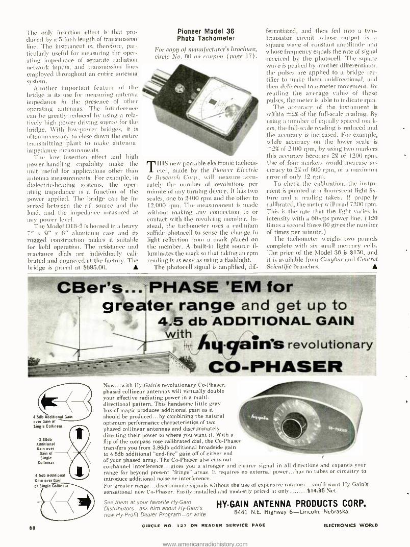
The only insertion effect is that pro- duced by a 5 -inch length of transmission line. The instrument is, therefore, par- ticularly useful for measuring the oper- ating impedance of separate radiation network inputs, and transmission lines employed throughout an entire antenna system.
Another important feature of the bridge is its use for measuring antenna impedance in the presence of other operating antennas. The interference can be greatly reduced by using a rela- tively high power driving source for the bridge. With low -power bridges, it is
often necessary to close down the entire transmitting plant to make antenna- impedance measurements.
The low insertion effect and high power- handling capability make the unit useful for applications other than antenna measurements. For example, in
dielectric -heating systems, the oper- ating impedance is a function of the power applied. The bridge can be in- serted between the r.f. source and the load, and the impedance measured at any power level.
The Model OIB -2 is housed in a heavy 7" x 9" x 6" aluminum case and its rugged construction makes it suitable for field operation. The resistance and reactance dials are individually cali- brated and engraved at the factory. The bridge is priced at $695.00.
Pioneer Model 36 Photo Tachometer
For copy of manufacturer's brochure, circle No. 60 on coupon (page 17).
THIS new portable electronic tachom- eter, made by the Pioneer Electric
& Research Corp., will measure accu- rately the number of revolutions per minute of any turning device. It has two scales, one to 2400 rpm and the other to 12,000 rpm. The measurement is made without making any connection to or contact with the revolving member. In- stead, the tachometer uses a cadmium sulfide photocell to sense the change in light reflection from a mark placed on the member. A built -in light source il- luminates the mark so that taking an rpm reading is as easy as using a flashlight.
The photocell signal is amplified, dif-
ferentiated, and then fed into a two - transistor circuit whose output is a square wave of constant amplitude and whose frequency equals the rate of signal received by the photocell. The square wave is peaked by another differentiator. the pulses are applied to a bridge rec- tifier to make them unidirectional. and then delivered to a meter movement. By reading the average value of these pulses, the meter is able to indicate rpm.
The accuracy of the instrument is
within ±2% of the full -scale reading. By using a number of equally spaced mark- ers, the full -scale reading is reduced and the accuracy is increased. For example, while accuracy on the lower scale is
2% of 2400 rpm, by using two markers this accuracy becomes 2% of 1200 rpm. Use of four markers would increase ac- curacy to 2% of 600 rpm, or a maximum error of only 12 rpm.
To check the calibration, the instru- ment is pointed at a fluorescent light fix-
ture and a reading taken. If properly calibrated, the meter will read 7200 rpm. This is the rate that the light varies in intensity with a 60 -cps power line. (120 times a second times 60 gives the number of times per minute.)
The tachometer weighs two pounds complete with six small mercury cells. The price of the Model 36 is $150, and it is available from Graybar and Central Scientific branches.
CBer's.. PHASE 'EM for 111111.11111
greater range and get up to 4.5 db ADDITIONAL GAIN w'th h ` - ga.n's revolutionary
CO- PHASER
4.5db A ditional Gain over Gain of Single Collinear
3.86db Additional Gain over
Gain of Single
Collinear
4.5db Additional Gain over Gain
of Single Collinear
88
Now ... with Hy- Gain's revolutionary ('u- I'haser, phased collinear antennas will virtually double your effective radiating power in a multi- directional pattern. This handsome little gray box of magic produces additional gain as it should be produced...by combining the natural optimum performance characteristics of two phased collinear antennas and discriminately directing their power to where you want it. With a flip of the compass rose calibrated dial, the Co- Phaser transfers you from 3.86db additional broadside gain to 4.5db additional "end -fire" gain off of either end of your phased array. The Co- Phaser also cuts out co- channel interference...gives you a stronger and clearer signal in all directions and expands your range far beyond present "fringe" areas. It requires no external power...has no tubes or circuitry to introduce additional noise or interference. For greater range...discriminate signals without the use of expensive rotators...you'll want Hy- Gain's sensational new Co- Phaser. Easily installed and modestly priced at only $14.95 Net
See them at your favorite Hy -Gain Distributors ask him about Hy- Gain's new Hy- Profit Dealer Program or write
HY -GAIN ANTENNA PRODUCTS CORP. 8441 N.E. Highway 6- Lincoln, Nebraska
CIRCLE NO. 127 ON READER SERVICE PAGE ELECTRONICS WORLD
www.americanradiohistory.com
OVER 2000 COMPONENTS... Amplifiers
Phono Equipment
Tuners
Tape Machines
Speakers & Cabinets
Accessories
...are covered in the 1964
edition of the
= T - ïS EREOHI f DIRECTORYU,ïrgÇ
r.
:e . çt STEREO/HI-Fl DIRECTOR
It's the world's most comprehensive BUYERS' GUIDE to the hi -fi market. Everything you need in sound is fea- tured in the 180 product -packed pages of the 1964 STEREO /HI -FI DIREC- TORY. It gives you the vital statistics -photos, prices, and performance data -on over 2000 components from 177 dif- ferent manufacturers. It's the best way to see and compare speakers, enclo1 sures, cartridges, changers, amplifiers, tone arms, FM tuners, tape recorde and FM antennas before you buy.
Plus you get these special features: How to select an FM tuner Tips on buying Tape Recorders Complete listing of all FM Stereo Multiplex
Stations broadcasting in the U.S. and Canada (as of September 1963).
November, 1963
Complete listing of all Hi -Fi dealers throughout theUnited States.
The 1964 STEREO /HI -FI DIRECTORY is your indispensable guide to the total -sound market. It goes on sale October 1st at your favorite newsstand or hi -fi dealer's. Or fill in this coupon and we'll send you a copy.
Price only $1.00
Ziff -Davis Service Division Dept. SD EW113 589 Broadway, New York 12, New York
Please send me a copy of the 1964 STEREO/HI-F1 DIRECTORY. I enclose $1.00, the cost of the DIREC- TORY, plus 150 to cover mailing and handling charges. (Canada & Overseas: $1.25 plus 250 postage).
NAME
ADDRESS
CITY ZONE STATE (Add 4% sales tax if N.Y.C. resident)
91
www.americanradiohistory.com
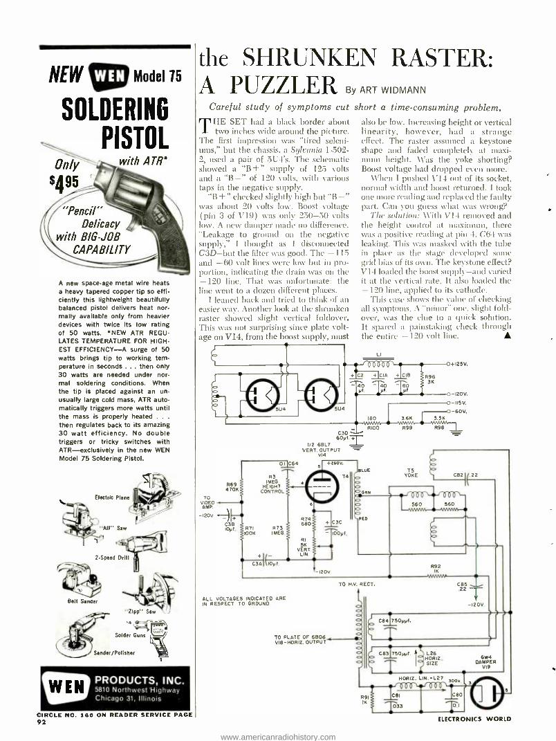
NEW 1:11) Model 15
SOLDERING
PISTOL Only with ATR*
$495
"Pencil" Delicacy
with BIG -JOB CAPABILITY
A new space -age metal wire heats a heavy tapered copper tip so effi- ciently this lightweight beautifully balanced pistol delivers heat nor- mally available only from heavier devices with twice its low rating of 50 watts. *NEW ATR REGU- LATES TEMPERATURE FOR HIGH- EST EFFICIENCY -A surge of 50 watts brings tip to working tem- perature in seconds ... then only 30 watts are needed under nor- mal soldering conditions. When the tip is placed against an un- usually large cold mass. ATR auto- matically triggers more watts until the mass is properly heated . . .
then regulates back to its amazing 30 watt efficiency. No double triggers or tricky switches with ATR -exclusively in the new WEN Model 75 Soldering Pistol.
Electric Plane f l
L- "AII" Saw
Belt Sander
"Zinn" Saw
Solder Guns
Sander /Polisher
IZID PRODUCTS, INC. 5810 Northwest 'Highway Chicago 31, Illinois
CIRCLE NO. 160 ON READER SERVICE PAGE 92
the SHRUNKEN RASTER: APUZZLER By ART WIDMANN
Careful study of symptoms cut short a time -consuming problem. rhHE SET had a black border about
two inches wide around the picture. The first impression was "tired seleni- ums," but the chassis, a Sylvania 1-502- 2, used a pair of 5Ú4's. The schematic showed a "B +" supply of 125 volts and a "B -" of 120 volts, with various taps in the negative supply.
"B +" checked slightly high but "B -" was about 20 volts low. Boost voltage (pin 3 of V19) %vas only 230 -50 volts low. A new damper made no difference. "Leakage to ground on the negative supply," I thought as I disconnected C3D -but the filter was good. The -115 and -60 volt lines were low but in pro- portion, indicating the drain was on the -120 line. That was unfortunate: the line went to a dozen different places.
I leaned back and tried to think of an easier way. Another look at the shrunken raster showed slight vertical foldover. This was not surprising since plate volt- age on V14, from the boost supply, must
also be low. Increasing height or vertical linearity, however, had a strange effect. The raster assumed a keystone shape and faded completely at maxi- mum height. Was the yoke shorting? Boost voltage had dropped even more.
When I pushed V14 out of its socket, normal width and boost returned. I took one more reading and replaced the faulty part. Can you guess what %vas wrong?
The solution: With V14 removed and the height control at maximum, there was a positive reading at pin 4. C64 was leaking. This was masked with the tube in place as the stage developed some grid bias of its own. The keystone effect? V14 loaded the boost supply-and varied it at the vertical rate. It also loaded the -120 line, applied to its cathode.
This case shows the value of checking all symptoms. A "minor" one, slight fold - over, was the clue to a quick solution. It spared a painstaking check through the entire -120 volt line.
LI
R96 3K
180 36K 3.3K
R69 470e
TO VIDEO AMP.
-120V
C38 Ioyf.
011c64
R3 IMEG.
HEIGHT CONTROL
R71 R73 IOOK MEG I
C3A1 Oyf.
C3D 60yf.T 1/2 6BL7
VERT. OUTPUT - V14
260v.
T4
R100
+1259.
120V.
115V.
60V.
R99 R98
75 YOKE CO2 22
C3C
1000.
ALL VOLTAGES INDICATED ARE IN RESPECT TO GROUND
-120V
o 70 PLATE OF 6806_ V18- HORIZ. OUTPUT d o
3
C841750yyf.
22
b C83t750Pyf tirs L26 o °HORIZ. T SIZE
R91
6W4 DAMPER
V19
C81
ELECTRONICS WORLD
www.americanradiohistory.com
Get this BIG BONUS with your purchase of a
FREE! PHoToFAcT Library!
this 4- drawer deluxe FILE CABINET worth $38.95
with your purchase of a
PHOTOFACT LIBRARY consisting of 180 SETS
own the world's finest TV -radio service data Now, more than ever, it pays to own a PHOTOFACT Library -the time -saving troubleshooting partner that helps you earn more daily. Now, you can start or complete your PHOTOFACT Library the special Easy -Buy way, and get absolutely FREE with your purchase, the deluxe 4- drawer File Cabinet, plus valuable extras described below!
OWN A PHOTOFACT LIBRARY THE EASY -BUY WAY:
Only $10 down 30 months to pay No interest or carrying charges Prepaid transportation Add -on privilege of a year's advance subscrip- tion to current Photofact on the sanie Easy -Buy contract Save 30c per Set special $1.95 price applies on Easy -Buy (instead of regular $2.25 price)
PLUS: In addition to the deluxe File Cabinet, you get a complete Color TV Servicing Course, 2nd Class Radiotelephone License Course, Transistor Radio Servicing Course, and Test Equipment Guide!
4 Ways to Select Your PHOTOFACT Library 1. Complete your present PHOTOFACT Library 9. Order a PHOTOFACT "Starter" Library -180 Sets
(Sets 301 to 480- coverage from 1955 to 1960 - only $11.33 per month).
:3. Order by brand name and year -see the handy selection chart at your Distributor.
4. Order a complete PHOTOFACT Library -get FREE File Cabinets to accommodate the entire library, the Courses listed above, plus an 8 -vol- ume Set of "101 Ways" Test Instrument books worth $18.50.
A PHOTOFACT LIBRARY PAYS ITS OWN WAY- ORDER TODAY AND GET THE FREE BONUS EXTRAS
See your Distributor for Easy -Buy Library details, or send coupon today! Ask also about a Standing Order Subscription to current PHOTOFACT -FREE File Cabinet also available!
OFFER AVAILABLE ONLY UNTIL MAY 15, 1964
November, 1 Ç '
HOWARD W. SAMS & CO., INC. Howard W. Saves & Co., Inc., Dept. 5 -L3 4300 W. 62nd St., Indianapolis 6, Ind.
11 Send full information on Easy -Buy Plan
My Distributor is
Shop Name
Attn
Address
City Zone State
CIRCLE NO. 145 ON READER SERVICE PAGE
J 93
www.americanradiohistory.com
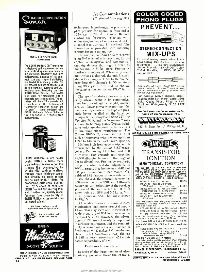
MODEL G CITIZEN'S BAND
TRANSCEIVER
The SONAR Model G CB Transceiver is designed and engineered for use in all critical applications demand- ing maximum reliability and high performance. Because of its com- pact size and simple installation, the Model G is ideally suited for the growing number of applications by non -technical business and pro- fessional men. Featuring the new SONAR Noise Silencer, the Model G is Class "B" modulated with 8
channels crystal -controlled. The re- ceiver will tune 23 channels. All connections of the custom -wired transmitter / receiver circuit are fail -proof - hand soldered with ERSIN Multicore 5 -Core Solder - for dependable, trouble -free performance.
ERSIN Multicore 5 -Core Solder costs SONAR a trifle more than ordinary solders - but this is more than compensated for by the vital savings realized through more joints -per -pound, and virtually no costly rejects due to cold or H R joints. For
production efficiency, guaran- teed by 5 cores of exclusive ERSIN flux and fast melting thin - wall construction, quality manu- facturers have come to rely on
ERSIN Multicore, the world's fin- est cored solder.
Multicore conforms to all applicable Federal Specifications /'
tFor information, write Department MS 43
ERSIN
5 -CORE * SOLDER
MULTICORE SALES CORPORATION PORT WASHINGTON NEW YORK
CIRCLE NO. 169 ON READER SERVICE PAGE 94
Jet Communications (Continued from page 30)
techniques. Interchangeable power sup- plies provide for operation from either 115- v.a.c. or 28- v.d.c. sources. Remote control for frequency selection with either single -channel simplex or double - channel 6 -mc. spread is provided. The transmitter is provided with metering circuits for tune -up and test.
The companion Collins 51X -2 receiver is an 880 -channel unit providing for re- ception of navigation and communica- tion signals over the range of 108.0 to 151.95 mc. in 50 -kc. steps. Frequency synthesis is employed. Where only com- munications is desired, the unit is avail- able with a range of 118.0 to 151.95 mc. providing 680 channels in 50 -kc. steps using 38 crystals. Size and weight are the same as the companion 17L -7 trans- mitter.
The use of solid -state devices is espe- cially advantageous in jet communica- tions because of lighter weight, smaller size, and lower power consumption. Nu- merous equipments of this type are pres- ently being installed on the latest jet transports, including the Boeing 727, the Douglas DC -8, and the Grumman "Gulf- stream" turbo -prop plane. Typical solid - state units are designed as transceivers to minimize space requirements. The Collins 618M -1C, shown in Fig. 4, is such a transceiver with a coverage from 116.0 to 149.95 mc. with 25 -kc. spacing.
Modern high -frequency equipment is represented by the Collins 61ST trans- ceiver. Employing 14 tubes and 100 transistors, this versatile unit provides 28,000 discrete channels in the range of 2.0 to 29.999 mc. Frequency synthesis, using a master oscillator adjustable to WWV, results in a frequency stability of 0.8 part -per -millionth per month. Ca- pable of SSB ( upper or lower sideband) or straight AM, the transmitter provides 400 -watts p.e.p. on SSB and 110 -watts carrier on AM. Selectivity of the receiver portion of the unit is 2.7 kc. at 6 -db down points on SSB and 5.5 kc. at 6 -db down points on AM. The unit is shown in Fig. 5.
All aviation radio air -to- ground com- munications equipment uses AM modu- lation. This may seem odd, in view of the widespread use of FM in other commu- nications services. However, the advan- tages of FM are not nearly as important in airborne equipment, and the compati- bility of communication and navigation facilities on v.h.f. makes AM the obvious choice. In h.f. communications, the use of SSB or very- narrow -band AM elimi- nates the possibility of FM.
Problems Encountered
Because of the large amount of elec- tronic equipment on board the jet trans-
COLOR CODED PHONO PLUGS
PREVENT...
STEREO -CONNECTION
MIX -UPS To avoid wiring errors when inter- connecting two pieces of stereo equipment . use new Switchcraft phono plugs with "SNAP -ON" Color Coded Handles, in RED, BLACK and WHITE.
Just solder wire and "SNAP -ON" plastic handle. Handle "locks-on" plug to give you a permanent finger grip when dis- connecting equipment. For positive Stereo channel identi- fication order Switchcraft Series 3508 Color Coded Phono Plugs in Red, Black or White, -only $0.25 LIST PRICE. Contact your dealer or write us for
name of dealer nearest you.
`5577 N. Elston Ave. / Chicago 30, Ill.
CIRCLE NO. 153 ON READER SERVICE PAGE
TRANSISTOR IGNITION
READY -TO- INSTALL CONVERSIONS
YOU can get TOP MILEAGE. HIGHEST PERFORM- ANCE. LONGER POINT & PLUG LIFE. BETTER WIN- TER STARTING. and MANY OTHER ADVANTAGES with one of our INEXPENSIVE TRANSFIRE systems. These include HERMETICALLY SEALED AMPLIFIER. HIGH -RATIO COIL, BALLASTS. Leads & hardware.
MODEL T 6 or 12v. neg. grd. $39 95
MODEL 12 TWO TRANSISTORS, 250:1 coil $44 95
MODEL TP 6 or 12v. pos. grd. direct Installation wo. insulating points $54.95
MODEL TS Special, 40kv system 559.95 MODEL TS? TWO TRANSISTORS,
400:1 coil $49.95
TWO- TRANSISTOR KITS Everything needed to build conversion. Includes transistors, coil, ballasts. heat sink. decal. etc.
KT2 with TX250 coil for 30kv output . $34.95 KTS2 with 1400 coil for 40kv output . $39.95 KT1 one transistor with 400:1 coil . $27.95
6 or 12v. Negative -ground only. Point insulation kit adapts to positive ground, $2.50 pp. 1 oz. Epoxy potting plastic In mixing bag $1.95 pp
HIGH -RATIO IGNITION COILS with free circuit dia- gram.
TX250 Heavy duty coil 250:1 ratio $ 9.95 T400 HIGH EFFICIENCY 400:1 coil for
HIGHER OUTPUT and -or LOWER TRANSISTOR VOLTAGE $11.95
FULL LINE of PARTS at NET PRICES. Free lists. Marine models available. When ordering, specify voltage and car. Add postage for 4 lbs. on kits and cony's; 3 lbs. on coils $5.00 deposit with COD's. Dealer & Distributor Opportunities.
PALMER ELECTRONICS LABORATORIES Inc CARLISLE 1, MASS. 617 -AL 6 -2626
CIRCLE NO. 141 ON READER SERVICE PAGE ELECTRONICS WORLD
www.americanradiohistory.com
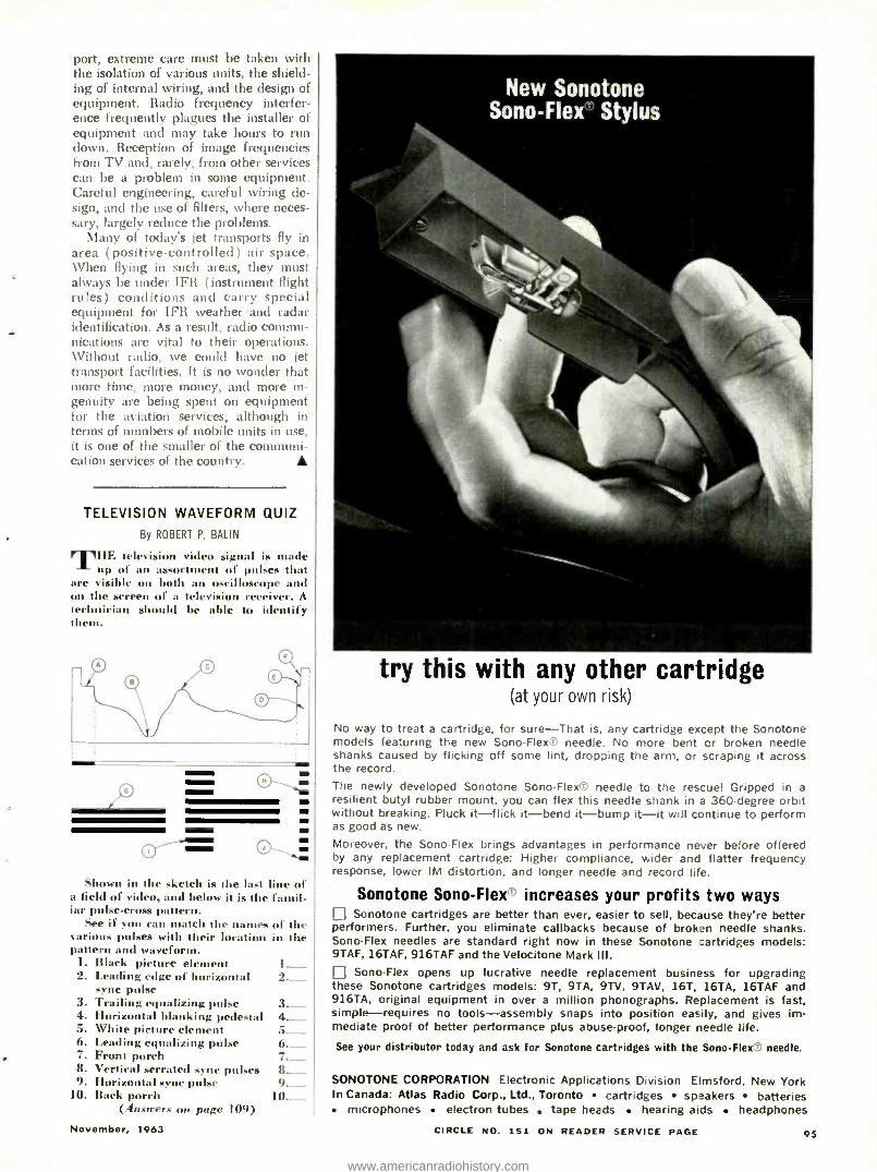
port, extreme care must be taken with the isolation of various units, the shield- ing of internal wiring, and the design of equipment. Radio frequency interfer- ence frequently plagues the installer of equipment and may take hours to run down. Reception of image frequencies from TV and, rarely, from other services can be a problem in some equipment. Careful engineering, careful wiring de- sign, and the use of filters, where neces- sary, largely reduce the problems.
Many of today's jet transports fly in area (positive -controlled) air space. When flying in such areas, they must always be under IFR (instrument flight rules) conditions and carry special equipment for IFR weather and radar identification. As a result, radio commu- nications are vital to their operations. Without radio, we could have no jet transport facilities. It is no wonder that more time, more money, and more in- genuity are being spent on equipment for the aviation services, although in terms of numbers of mobile units in use, it is one of the smaller of the communi- cation services of the country.
TELEVISION WAVEFORM QUIZ
By ROBERT P. BALIN
T111., t leci'. yiáeo signal is ruade up of an assortment of poles that
are visible on both an oscilloscope and on the screen of a tleyis' receiver. .1
technician sl Id be able to identify them.
Shown in the sketch is the last line of a licld of video, and below il is the famil- iar pule -cross pattern.
tier if you can match the names of the var' pules with their lot at' in the pattern and waveform.
I. Black picture clement I Leading edge of horizontal 2._ sync pulse
3. Trailing equalizing pulse 3._ 4. Horizontal blanking pedestal 4.- 5. White picture element 5.__ 6. Leading equalizing pulse 6. ___ 7. Front porch 7._ _
8. Vertical serrated sync pulses 8._ 9. Horizontal sync pule 9._
10. Back porch 10._ (Answers on page 1119)
November, 1963
New Sonotone Sono - Flex' Stylus
try this with any other cartridge (at your own risk)
No way to treat a cartridge, for sure -That is, any cartridge except the Sonotone models featuring the new Sono - Flexs needle. No more bent or broken needle shanks caused by flicking off some lint, dropping the arm, or scraping it across the record.
The newly developed Sonotone SonoFlexD needle to the rescue! Gripped in a resilient butyl rubber mount, you can flex this needle shank in a 360 -degree orbit without breaking. Pluck it -flick it -bend it -bump it -it will continue to perform as good as new.
Moreover, the Sono -Flex brings advantages in performance never before offered by any replacement cartridge: Higher compliance, wider and flatter frequency response, lower IM distortion, and longer needle and record life.
Sonotone Sono -Flex" increases your profits two ways Li Sonotone cartridges are better than ever, easier to sell, because they're better performers. Further, you eliminate callbacks because of broken needle shanks. Sono -Flex needles are standard right now in these Sonotone : artridges models: 9TAF, 16TAF, 916TAF and the Velocitone Mark III.
Sono -Flex opens up lucrative needle replacement business for upgrading these Sonotone cartridges models: 9T, 9TA, 9TV, 9TAV, 16T, 16TA, 16TAF and 916TA, original equipment in over a million phonographs. Replacement is fast, simple- requires no tools -assembly snaps into position easily, and gives im- mediate proof of better performance plus abuse -proof, longer needle life.
See your distributor today and ask for Sonotone cartridges with the Sono -Flex needle.
SONOTONE CORPORATION Electronic Applications Division Elmsford, New York In Canada: Atlas Radio Corp., Ltd., Toronto cartridges speakers batteries
microphones electron tubes tape heads hearing aids headphones
CIRCLE NO. 151 ON READER SERVICE PAGE 95
www.americanradiohistory.com
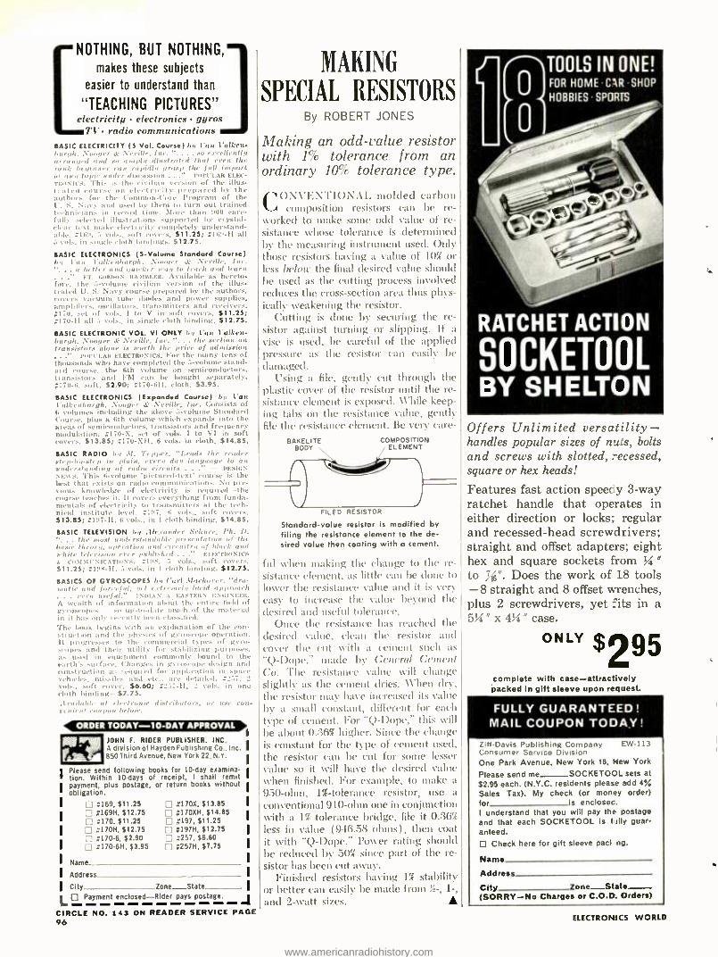
NOTHING, BUT NOTHING,
makes these subjects
"TEACHING
to understand than
TEACHING PICTURES 11
electricity electronics gyros TI - radio communications
BASIC ELECTRICITY (5 Vol. Course) by Van Vulkea I. . .. su excellently
,Il,i.aru(rd that even the uov ran rapidly grasp the fall import
Iir mater discussion ... rue PLAN EI.EC- tv s Its. This is the civilian version of the illus- trated course on electricity prepared by the authors for the Common -Core Program of the U. S. Navy and used by them to turn out trained technicians in record tinte. More than 900 care- full I,ted illustrations supported by crystal-
electricity completely understand - aide , I... .,,f. ,,.,,
. $11.25; ;169 -11 all
BASIC ELECTRONICS (S- Volume Standard Course) \,. .l' . \'r r,lb, fur.
Fr. Gums. ISA>nn.Ea. Available as hereto - fore, the 5-volume civilian version of the illus- trated U. S. Navy course prepared by the authors, rovers vacuum tube diodes and power supplies, amplifiers, oscillators. transmitters and receivers. ;170, cet of vols. 1 to V in soft covers. $11.25; ;170 -11 all 3 vols.. in single cloth binding. $12.75.
BASIC ELECTRONIC VOL. VI ONLY by l'un Talker. laugh, Nuogrr & .Neville, ho. "... the section on transistors alone is worth the price of admission
l'lll'CI.AIt EI.ECTRIINICS. For the many tens of thousands who have completed the 5-volume stand- ard course, the 6th volume on semiconductors, transistors and FAl can be bought separately. ¡170 -6. soft, $2.90; :170 -611. cloth. $3.95.
BASIC ELECTRONICS (Expanded Course) by l'art l'alkenbargh. Nuogrr & .Neville, Inc. Consists of 6 volumes including the above 5- volume Standard Course. plus a 6th volume which expands into the areas of semiconductors. transistors and frequency modulation. ;170 -X, set of vols. I to VI in soft covers. $13.85; :170 -XH. 6 vols. in cloth. $14.85.
BASIC RADIO by 31. Tepper. "Leads Ihr reader step -hy -step ire plain. every darn lia, /auge to an understanding of radio circuits . DESIGN NEWS. This h- volume 'pictured -text' course is the best that exists on radio communications. No pre- vious knowledge of electricity is required the course teaches it. It envers everything from funda- mentals of electricity to transmitters at the tech- nical institute level. ;197 6 vols., sort inners. $13.85; ;197 -11, ti vols.. in I cloth binding. $14.85.
BASIC TELEVISION by Alexander Scharr, Ph. 11.
. the uruat understandable presentation of the basil. theory, operation and rirruitry of black and vhite television ever pablislnd ELECTRONICS A COM M l' NICATIIINS. :19S, vols., soft rovers. 511.25; L111S -H, 5 vols. in 1 cloth binding. $12.75.
BASICS OF GYROSCOPES by Carl .11urhorer. "dra- tir mad furtif sal, yet extremely lurid approach
very useful. 1 MOAN .c EASTERN ENGI NEEII. A wealth of information alsrilt the entire field of gyroscopes so alp -to -Ilote touch of the material in it has only recently been classified. The book begins with an explanation of the con- struction and the physics of gyroscope operation. It progresses to the commercial types of gyro- scopes and their utility for stabilizing purposes, as used in equipment rum ly bound to the earth's surface. Changes in gyroscope design and construction :c: required for application in space vehicles. missiles and etc.. are detailed. : vals soft rover. $6.60; _57 -II, I vols. in one cloth binding $7.75. .11'11ilnl.le nI - Ironic distributors, or use eon.
JOHN F. RIDER PUBLISHER. INC. A division of Hayden Publishing Co.. Inc. 850 Third Avenue, New York 22, N.Y.
Please send following books for 10 -day examina- tion. Within 10 -days of receipt, I shall remit payment, plus postage, or return books without obligation.
x169,$11.25 [] #170X, $13.85 :169H, $12.75 x170XH, $14.85 ;170, $11.25 #197, $11.25
n :170H, $12.75 #197H. $12.75 ;170.6, $2.90 #257, $6.60 :170 -6H, $3.95 El #257H, $7.75
Name
Address
City Zone State
L[; Payment enclosed Rider pays postage. j CIRCLE NO. 143 ON READER SERVICE PAGE 96
MAKING
SPECIAL RESISTORS By ROBERT JONES
Making an odd -value resistor with 1% tolerance from an ordinary 10% tolerance type.
CONVENTIONAL molded carbon composition resistors can be re-
worked to make some odd value of re- sistance whose tolerance is determined by the measuring instrument used. Only those resistors having a value of 10% or less below the final desired value should be used as the cutting process involved reduces the cross- section area thus phys- ically weakening the resistor.
Cutting is done by securing the re- sistor against turning Or slipping. If a vise is used, be careful of the applied pressure as the resistor can easily be damaged.
Using a file, gently cut through the plastic cover of the resistor until the re- sistance element is exposed. While keep- ing tabs on the resistance value, gently file the resistance element. Be very care-
BAKELITE BODY
COMPOSITION ELEMENT
FILED RESISTOR
Standard -value resistor is modified by filing the resistance element to the de- sired value then coating with a cement.
fill when making the change to the re- sistance clement, as little can be clone to lower the resistance value and it is very easy to increase the value beyond the desired and useful tolerance.
Once the resistance has reached the desired value, clean the resistor and cover the cut with a cement such as `Q- Dope," made by ( ;(vuv'al Cement Co. The resistance value will change slightly as the cement dries. \ \'hen dry, the resistor may have increased its value by a small constant, different for each type of cement. For "Q- Dope," this will be about 0.:361 higher. Since the change is constant for the type of cement used. the resistor can be cut for some lesser value so it will have the desired value when finished. For example, to make a 950 -ohm, 11- tolerance resistor, use a conventional 910 -ohm one in conjunction with a 1% tolerance bridge, file it 0.36`,( less in value (946.58 ohms), then coat it with "Q- Dope." Power rating should be reduced by 501 since part of the re- sistor has been cut away.
Finished resistors having 1( stability or better can easily be made from ) -, 1 -,
and 2 -watt sizes.
TOOLS IN ONE! FOR HOME CAR SHOP
HOBBIES SPORTS
RATCHET ACTION
SOCKETOOL BY SHELTON
Offers Unlimited versatility - handles popular sizes of nuts, bolts and screws with slotted, recessed, square or hex heads!
Features fast action speedy 3 -way ratchet handle that operates in either direction or locks; regular and recessed -head screwdrivers; straight and offset adapters; eight hex and square sockets from % "
to 316 ". Does the work of 18 tools -8 straight and 8 offset wrenches, plus 2 screwdrivers, yet -its in a 5 %" x 4 %" case.
ONLY 295 complete with case -attractively packed in gift sleeve upon request.
FULLY GUARANTEED! MAIL COUPON TODAY!
Ziff -Davis Publishing Company EW -113 Consumer Service Division One Park Avenue, New York 16, New York
Please send me SOCKETOOL sets at
$2.95 each. (N.Y.C. residents please add 4%
Sales Tax). My check (or money order) for is enclosec. I understand that you will pay the postage and that each SOCKETOOL is f ally guar- anteed.
O Check here for gift sleeve pact ng.
Name
Address
City lone -State (SORRY -No Charges or C.O.D. Orders)
ELECTRONICS WORLD
www.americanradiohistory.com
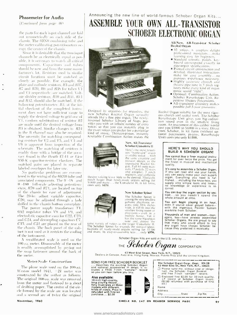
Phasemeter for Audio (Colttinrlrel from paw 1(i1
the parts for each input channel are laid out symmetrically on each side of the chassis. The 6B \6 combining tube and the meter -calibrating potentiometers oc- cupy the center of the chassis.
Since it is desirable that the two input channels be as electrically equal as pos- sible, it is necessary to match all critical components. Capacitors and tubes should be new and from the sanie manu - facturer's lot. Resistors used in similar circuit locations must be matched as closely as possible. For example, the plate and cathode resistors, R5 and R :37, R7 and R:39, R6 :und R :35 for tubes V1 and V4 respectively, arc matched. Volt- age divider resistors, R10 and R41, R11 and R-12.. should also be matched. If the balancing potentiometer, R3, at the ini- tial checkout of the completed instru- ment sloes not have sufficient range to supply the desired voltage to grid ouc of V1, random substitutions of resistor R2 dIe made until the desired voltage from R :3 is obtained. Similar changes in R34 in the B channel may also be required. The necessity for matching correspond- ing resistors for 1'2 and 173, and \'3 and V6 is apparent from inspection tif the schematic. The matching of resistors is readily clone with a bridge of the accu- racy found in the heath IT -11 or Eico 950 -K capacitor- resistor checkers. The matched pairs are placed in separate labeled envelopes for later use.
Nuu particular problems are encoun- tered itt the wiring of the 613 N6 tube and associated components. The 0 -18 and 0 -1S0 full -scale adjusting potentiom- eters, R70 and R71, are located on top of the chassis for ease of adjustment. The 20 -kc. adjust variable capacitor, C20, may be adjusted through a hole drilled in the chassis bottom coverplate.
The power supply transformer -/'I, 0A2 regulator tubes V8 and 1'9, and electrolytic capacitor cans for C22, C2:3, and C24. and decoupling capacitors C7, C15, and C21 are placed on the retir of the chassis. The back panel of the cab- inet is not used as it restricts the cooling of the instrument.
A recalibrated scale is used on the 100 -tut. meter. Disassembly of the meter is readily accennplished by prying out the snap fasteners around the back of the meter.
Meier -Scale t:onstruetion
The phase scale used on the 100 -¡ta. Weston model 1941, 27 meter was constructed by the author as follows: The original 100 -,ua. scale was removed from the meter and fastened to a sheet of drafting paper. The center of the cir- cle formed by the scale arc was located and a second arc of twice the original
November, 1963
Announcing the new line of world -famous Schober Organ Kits...
ASSEMBLE YOUR OWN ALL-TRANSISTOR
SCHOBER ELECTRONIC ORGAN
Designed by organists for organists. the new Schober Recital Organ actually sounds like a fine pipe organ. The newly - invented Schober Library of Stops pro- vides you with an infinite number of extra voices so that you can instantly plug in the exact voices you prefer for a particular kind of music. Thirteen- piston, instantly resettable Combination Action makes the
New, All- Transistor Schober Consolette I I
here's the most luxuri- ous "home- size" organ available today ... with the same circuitry and musical design as the impressive Recital Or- gan. Full 61 -note man- uals, 17 pedals, 22 stops and coupler, 3 pitch registers, and authentic
theatre voicing leave little to be desired. Musicals much larger than ready -made organs selling for $1800 and more ... the Consolette I I, in kit form, costs only $850.
New Schober Spinet The Schober Spinet i-. among the very smallest genuine electronic or- gans: only 391/4 inches wide. it will fit into the smallest living room or playroom - even in a mobile home. Yet it has the same big-organ tone and almost the
same variety of voices as the larger Consolette ll. The Schober Spinet far exceeds the musical speci- fications of ready -made organs selling for $1100 and more. In easy -to- assemble kits ... only $550.
Schober
Organ Kits are in the U.S. only by ..
THE (24C
VI -\etc, :111 -Transistor Sc holier Recital Organ
12 voices. 6 couplers delight professional musicians... make learning easy for beginners. Standard console. pedals. key- board correspond exactly to pipe -organ specifications. Printed circuit construction and detailed. illustrated instructions make for easy assembly ...no previous experience necessary. Highly accurate church and theatre pipe tone in 5 pitch reg- isters make every kind of organ music sound "right ". Optional: Combination Action. Schober Reverbatape Unit. Re- petitive Theatre Percussions. All- transistor circuitry makes possible fall 5 -year ,guarantee.
Recital Organ suitable for the most rigor- ous church and recital work. The Schober Reverbatape Unit gives you big- auditor- ium sound even in the smallest living room. An instrument of this caliber would cost you $5000 to $6000 in a store. Direct from Schober, in kit form (without op- tional percussions, pistons. Reverhatape Unit) costs you only $1500.
HERE'S WHY YOU SHOULD BUILD A SCHOBER ORGAN!
You cannot buy a finer musical instru- ment for over twice the price. You get the finest in musical and mechanical quality. It's easy to assemble a Schober Organ. If you can read and use your hands. you can easily make your own superb organ. Everything you need is fur- nished ... including the know -how; you supply only simple tools and time - no knowledge or experience is re- quired. You can buy the organ section by sec - tion... so you needn't spend the whole amount at once.
You can begin playing in an hour, even if you've never played before - with the ingenious Pointer System available from Schober. Thousands of men and women -teen- agers. too -have already assembled Schober Organs. We are proud to say that many who could afford to buy any organ have chosen Schober be cause they preferred it musically.
,n CORPORATION
43 West 61st Street, New York. N.Y., 10023 Dealers in Canada. Australia. Hong Kong. Mexico. Puerto Rico and the United Kingdom.
SEND FOR FREE SCHOBER BOOKLET . Describes the exciting Schober Organ
and optional accessories in detail; it in- cludes a FREE 7 -inch "sampler" record so you can hear before you buy.
Also available: 10 -inch high -quality, long playing record... fully illustrates all three models with different kinds of music. Price is refunded with first kit purchase ... $2.00
The Schober Organ Corp., Dept. RN -28 43 West 61st St., New York, N.Y., 10023 D Please send me. without cost or obliga-
tion. the Schober Organ Booklet and free 7 -inch "sampler" record. Enclosed find $2.00 for 10 -inch quality, LP record of Schober Organ music. ($2.00 refunded with purchase of first kit.)
Name -
Address City State Lip No.
CIRCLE NO. 147 ON READER SERVICE PAGE
J 97
www.americanradiohistory.com
NEW FROM ATR
iie01 "the oldest name in radio"
Suggested $. Retail Price
. . . for those %'ho want the finest! Check the features of this all -new, all- transistor Model 707 Karadio by ATR ... features galore that make sales easier, keep users happier! Com- pare ... and without hesitation place your order NOW for the new all - transistor ATR Karadio.
Large easy -to -read illuminated dial. Finger tip tone control to adjust tone as you desire. 7 -tuned circuits including RF stage to provide maxi- mum sensitivity and selectivity Automatic volume control to keep signals strong and steady.
Utilizes "solid state' construction employing 7 semi. conductors (5 transistors and 2 diodes). Superheterodyne circuit. 3- Section Super "Magna -Wave' tuner. Hand wired. No printed circuitry. Has one -piece sell -contained chassis for easy instal- lation. "Fits -All universal construction. For use with prac- tically all import and American cars and trucks. Fits under dash or in -dash utilizing standard trim plate kits.
Comes complete with built -in speaker.
External speaker jack provided. Available for 12 -volt negative ground installations only. Low battery drain.
Neutral Gray -Tan baked enamel finish. Overall size approximately 51/2" deep o 61/2" wide o 2" high. Ship- ping Weight 5 lbs.
SEE YOUR ELECTRONIC PARTS DISTRIBUTOR WRITE FACTORY FOR FREE LITERATURE....
ATR ELECTRONICS, INC.
AIR Formerly American Television if Rodio Co
Quality Products Since 1931
ST. PAUL 5. MINNESOTA -U.S.A. CIRCLE NO. 164 ON READER SERVICE PAGE 98
radius drawn in pencil on the drafting paper. Lines were extended from the center point through the 0- and 100 -µa. calibration marks on the original meter scale to the new arc. These were labeled 0 (360) and 180, respectively. Addi- tional lines were extended for each 10 -pa. mark on the original scale. The distances between the extended lines on the new arc correspond to 18° for each segment of the arc. The segments were then divided into nine parts correspond- ing to 2° of phase, for the small seg- ments. The lines on the new arc for 0 °, 10 °, 20 °, 30 °, etc. were lengthened slightly and labeled at 0 (360), 30 (330), 60 (300) , etc. for the full -scale width. Since the calibrating marks are made at twice the final size of the meter face, slight errors in marking are of less consequence. The desired wording on the meter face was shown in pencil and the drawing given to a professional draftsman for inking. The finished draw- ing was then photographed at exactly half scale on process film and prints made on low shrinkage photographic paper. The new scale was cemented di- rectly over the original scale, the edges trimmed, and the scale re- installed in the meter.
Alignment The first step is to adjust the cathode -
coupled clippers. Apply 1.1 -1.4 volts of a 500 -cycle sine wave to the "A In" terminal. Connect an oscilloscope to the output of VI, pin 6 (see Fig. 4), and adjust R3 until clipping just starts on both the top and the bottom of the sine wave. It will be necessary to vary the input voltage slightly to obtain the best presentation of the scope screen. If sym- metrical clipping cannot be obtained, it may be necessary to replace R2 with an- other resistor as described elsewhere in this article. Reduce the input voltage to .10 -.13 volt, connect the scope to the output of V2, pin 6, and adjust for sym- metrical clipping by varying the setting of R14 and the input voltage. The Schmitt trigger may be adjusted by ob- serving the position of the pips on the waveform from V2. The slight change in the intensity of the trace is caused by feedback from the operation of the Schmitt. The pips should be made to fall just above and below the zero reference line by adjusting R24. A second method of adjusting the Schmitt is to connect the scope to the output of V3, pin 6. Reduce the input voltage to a very low level, about 10 mv., and adjust R24 for triggering on the lowest possible input. The B- channel clippers and Schmitt are adjusted exactly in the same manner as the A channel, since both channels are symmetrical.
The next step is the adjustment of the meter ranges. Apply about 10 volts of 500 cycles to both the A and B channels.
Set "F. S. Adjust," R68 on the front panel, to mid -range, the "Addition" switch, S3, to 180 °, the "Range" switch, S4, to 180 °, and adjust R71 on the chas- sis for full -scale meter deflection, 180 °. To adjust the 0 -18° range, it is necessary to apply 18° of phase shift to one of the input channels. The phase- shifting cir- cuit shown in Fig. 3B may be connected to the B channel and the reference signal to the A input. Set the phase -shift switch to 21.8° and vary the input frequency from the audio generator so that exactly 18° of shift is indicated on the 0 -180° range. The required frequency is about 375 cycles. Move the "Range" switch, S4, to 0 -18° and adjust R70 for exactly full scale.
The 20 -kc. adjustment is made as fol- lows: Apply 10 volts of a 20 -kc. sine wave to both A and B channels. Set the "Addition" switch to 180 °, the "Range" switch to 0 -180 °, and adjust trimmer, C20, through the hole in the bottom of the chassis until the meter reads exactly 180 °.
A final touch -up adjustment may be made by applying 500 cycles to both in- puts and alternately switching the volt- age input from 0.3 to 10 volts. If the meter pointer moves slightly on either the 0° or the 180° ranges, carefully ad- just R3 and R35, respectively, until changes in voltage input have no effect on the meter reading. This requires only a very slight movement of adjusting po- tentiometers R3 and R35. The instru- ment is now ready for use and should remain in adjustment for some time. As noted in the section on operation, the 6BN6 cathode resistor, "F. S. Adjust," R68 on the front panel, may require resetting as the instrument warms up.
Phasemeter readings at four phase angles were compared with results ob- tained with two high -quality commercial phasemeters of different design and with an oscilloscope. The phase -shift standard (Fig. 3B) at an input frequency of 500 cycles was used to obtain the required phase delay. The results from the sub- ject phasemeter compare favorably with the average readings of the commercial instruments.
Operation After a warm -up period of several
minutes, a signal source between 0.5- and 60 -volts r.m.s. and at any audio fre- quency is connected to both the A and B input channels of the instrument. The "Addition" switch, S3, is set at 180° and the "F. S. Adjust" control R68, set to obtain a meter reading of exactly 180 °. This setting remains quite con- stant once the instrument is warmed up. The installation of a check switch for temporarily connecting the two chan- nels was considered. However, leakage through the switch in the "off" position at high frequencies could decrease the
ELECTRONICS WORLD
www.americanradiohistory.com
accuracy of the instrument. The input to both channels is disconnected, switch S3 returned to 0 , and the instrument is ready for use.
If the reference signal is connected to the A channel and the unknown signal to the B channel, the operation of the direction circuit is as follows: With the rotary "Direction" switch, S1, counter- clockwise, push -button switch, S2, is de- pressed and the meter pointer moves toward the input with the leading phase shift. If insufficient movement occurs, the rotary switch is moved one position clockwise. This switch should not be ro- tated any more than is necessary to ob- tain a definite movement of the meter pointer, as at some frequencies, incor- rect indication of the leading phase will be obtained. The action of the direction circuit is to slightly retard the phase angle of the A channel only. Referring to Fig. lA, the dashed line near the refer- ence frequencies indicates the new posi- tion of the reference signal. In the case of a lagging input signal E., to the B
channel, depression of the direction but- ton shifts the A channel reference fre- quency in the direction of E., decreas- ing the phase difference between the two channels and causing the meter pointer to move to the left, i.e., in the direction of the A channel input termi- nals that are, in this example, the leading phase angle input. The effect with a leading unknown input is to increase the phase difference between the two signals causing the pointer to move to the right, i.e., in the direction of the leading input terminals.
In using the phasemeter, the author confines the limits of possible phase shift to plus or minus 180'. if phase shift is considered always positive, i.e., 0 to 360`, the meter is calibrated in the re- verse direction for angles from 180 to 360'. In this latter range, the direction circuit operates in the reverse direction, pointing to the terminals with lagging phase.
Before the advent of dual -speaker systems with crossover networks and of stereo with multiple speakers, the phas- ing of the various frequencies was of little consequence. Currently used high - fidelity systems cannot give superior sound reproduction unless phase is con- trolled. The author recently listened to a high -quality stereo system with a 15- inch cone speaker and several high -fre- quency units in each of two stereo en- closures. Reversing the phasing switch on the preamplifier when listening to a program rich in bass resulted in a muf- fling of the sound and the loss of direc- tional effect.
Phase shift within amplifiers may occur, particularly at low and high fre- quencies. For purposes of illustration, two amplifiers, not stereo, were evalu- ated with the phasemeter (see Fig. 6) .
November, 1963
NEW 1964 GIANT CATALOG
reat,- ALPrs LO AeCEr
loo's of near items listed for
first time
100's of pages packed with
saving'
Satisfaction GUARANTEED
or your money backt
I
MO MONEY DOWN PLUS NEW REVOLVING
CHARGE ACCOUNT
BURSTEIN- APPLEBEE CO. Dept. M, 1012 -14 McGee St., Kansas City 6, Mo.
Rush
I
i M
NAME _ -
ADDRESS_-
CITY_
me the FREE 1964 B -A Catalog.
STATE__
I
I
I I
I CIRCLE NO. 106 ON READER
FOR 37 YEARS THE OUTSTANDING
MOII V SAVING BUYING GUIDE FOR:
Stereo t. Hi -Fi Systems and Compo- nents Tape Recorders Electronic Parts, Tubes, Books Phonos 8 Rec. ords Ham Gear Test Instruments and Kits Cameras and Film Public Address Citizens Band Transistor 8 FM -AM Radios.
RUIN COUPON TODAY SERVICE PAGE
LOW -COST BUSINESS AIDS FOR RADIO -TV SERVICE
Order books, invoice forms, job ticket hooks, service call books, cash books and statement books for use with your rub- ber stamp. Customer file systems, book- keeping systems, many others. Write for FREE 32 PAGE CATALOG now.
OELRICH PUBLICATIONS 6556 Higgins Rd., Chicago, Ill. 60656
HI -FI COMPONENTS TAPE RECORDERS
SLEEP LEARN KITS
MERITAPE Low cos high ahrd.ng rap. m bot, res or
yu cans
y rec
rriT\ SEND FOR FREE CATALOG
DRESSNER 1523 JERICHO TPKE. \-1-11"/ NEW HYDE PARK 16 N.Y. \-1-11"/
GET
INT O ELECTRONICS C.T.I. training leads to s : '5
s technicians. field engrnccr;. specialists in communications, guided missiles. computers. radar and automation. Basic & advanced courses in theory & laboratory. Electronic Engi- neering Technology, an ECPD accredited Technical Institute curriculum. Assoc. degree in 29 mos. B.S. also obtainable G I. approved. Graduates in ail branches of electronics with major companies. Start Feb.. Sept. Dorms. campus. High
graduate or equtcalent. for catalog.
VALPARAISO TECHNICAL INSTITUTE Dept. RD. Valparaiso, Indiana
99
www.americanradiohistory.com
NEW! ENGINEERI r UG
15 high fidelity
stereo albums for the price
of 0I1e
Now, 8 hours of full.range, true, high fidelity stereophonic music, or 16 monaural hours, can be yours on one 7" reel, with the revolutionary new Roberts Cross Field "770" Tape Recorder. The aver- age tape cost per album: only 33e. The "770" has an exclusive patented third head, the Cross Field Head, which separates recording and biasing functions. The result: the "770" records 40 to 22,000 cps, producing true fidelity at 17/8 fps and preserving the high frequency harmonics that breathe life into music playback. The Cross Field playback head has a gap width of only 40 micro - inches, the smallest, most responsive head ever engineered. For this head, Roberts employs NC -88, a new alloy, that is practically wear-proof. Other features: 2- speed, electrically-switched, heavy -duty hysteresis synchronous motor, minis- cule wow and flutter at slow speeds; special ven- tilation system keeps the "770" cool even after 8 hours; two 5" x 7" self- contained elliptical, extended -range, heavy -duty Alnico V- magnet speakers; new automatic total shut -off. $499.95.
SEE ROBERTS TAPE RECORDERS AT BETTER PHOTO AND SOUND CENTERS $269.95- $599.95
Specifications: 71/2, 33/4, 17/1 fps. Power Amplifier Output: 12 watts Frequency response: at 71/2
ips, 40 to 22,000 cps -i- 2 db; at 33/4 ips, 40 to 18,000 cps - 2 db; at 17/8 ips, 40 to 13,000 cps
3 db Signal to noise ratio: - 55 below 0
recorded level Wow and flutter: at 71/2 ips, less
than 0.12% rms; at 33/4 ips, less than 0.20%; at 1T /8 ips, less than 0.30% Blower vent system 2 large stereo 5" x 7" elliptical, extended range, heavy duty Alnico V magnet speakers Hysteresis synchronous instantaneous electrically controlled 2 speed motor Automatic total shutoff Oper-
ates Horizontally or Vertically.
FREE BOOKLET! "40 AND MORE WAYS TO A ROBERTS TAPE RECORDER"
U
Roberts Electronics, Inc. 5978 Bowcroft, Dept. EW -11, Los Angeles 16, Calif. Please send free booklet []
Please send me complete information about Roberts Tape Recorders
Name
Address
City State_
IN CANADA: 1. M. Nelson Electronics Ltd., 7725 Adera St.,
Vancouver 14. B. C. (Prices slightly higher in Canada)
CIRCLE NO. 144 ON READER SERVICE PAGE 100
Amplifier A, a high- quality unit, was compared to amplifier B, a low -cost pre- amplifier- amplifier unit set with the controls flat. A 16 -ohm resistor was connected across the amplifier outputs. Drastic changes in phase occur with unit B at the high and low end compared to the relative flatness of unit A. Ob- viously these two amplifiers could not be used successfully in a dual- channel stereo system.
Another example of phase shift occurs in crossover networks supplying bass and midrange speaker systems. The crossover system checked with the phasemeter was constructed with oil -
filled capacitors and heavy wire in the inductances. The circuit is a constant - resistance design with 12 -db attenuation per octave. During these tests, amplifier output was 5 watts and 16 -ohm resistors were used on the crossover outputs. It will be noted in Fig. 7 that the phase changes markedly with frequency. The phase shift on both the high- and low - pass networks is very close to +90° and -90° at the 3 -db crossover point. There
is a constant phase difference approach- ing the theoretical 180° over the entire frequency range, consequently the speaker connections should be adjusted so that the cone movement of both units is in the same direction at the crossover frequency.
A third example of the use of the phasemeter in equipment evaluation is
shown in Fig. 8. In matrixing -type mul- tiplex converters the ( L + R ) signal is
often routed through a 15 -kc. low -pass filter. The particular filter used in this test was down 3 db at 19 kc. and indi- cated a phase shift at the higher fre- quencies. The 23 -kc. to 53 -kc. bandpass filter used in the (L- R) channel of mul- tiplex converters showed appreciable phase shift above and below the 38 -kc. suppressed -carrier frequency. Since the outputs from the 15 -kc. low -pass and the 23 -kc. to 53 -kc. bandpass filters are com- bined in the detector matrixing system of the converter, phase shifts of the di- rection and amount such as shown in
Fig. 8 do not lead to distortion -free re- production.
REFERENCES
1. Kretimcr, E. R.: p. 114, Electronics. Octo- ber, 1949
2. Terman, F. E. & Pettit, J. M.: "Electronic Measurements," McGraw -Hill Book Co., Sec- ond Edition, 1952
3. Partridge. G. R.: "Principles of Electronic In- struments," Prentice -Hall, Inc., 1958
4. Electrical Design News, January 1958
5. Ginzton, E. L.: p. 60. Electronics, May 1942
6. Goldmuntz, L. A. & Kraus, H. L.: p. 1172. Proceedings of the IRE, September 1948
7. U.S. Patent 2,370,692 to J. E. Sheperd
8. Holman. F. S., Jr.: p. 181, Electronics. Au- gust 1953
9. Yu, Y. P.: p. 14, Electronic Equipment, No- vember 1954 & p. 99, Electronics, September 1958
10. Woodbury. J. R.: p. 56, Electronics, Septem- ber 22. 1961
11. Millman. J. & Taub. H.: "Pulse and Digital Circuits," McGraw -Hill Book Co., 1956
STROMBERG G 64 WATT STEREO AMPLIFIER SALE
REGULAR McGEE'S d. $199.50 PRICE 99.95
siet.ec Carload Purchase Sale! Arw F.,ri,,, C.irtoned ti watt 4:12 watts per channel, t;rco -11, Fi Audio Amplifier. Meeel AS114 4110. It's all there Is in quality and value. Made to sell at $200.00. McGee Offers them for Only $99.95. Metal cover. $5.95 extra. Works with any record changer :Intl tuner. Use with any I. I iii -F1 speakers. Only 500 to sell, order yours now. Shipping weight. 12 the. Combination offer: AS0-880. 04 watt Stereo amplifier with Garrard Type 'A.' Shure M711 cartridge and two .Stephens 120FR wide-range 1!- speakers. all for only $285.40. Wood hose for Type A. $4.95. LRS3. 45 RPM Spindle. $3.80. tlewald N80111. FM -AM self -powered tuner, $54.50 extra.
M w ` ,wo 4 ,.:
s 1:4 .T.,
ST .....r». .. .43
SPECIFICATIONS The StrombergCarlson ASR -880 Is one of the most powerful stereo amplifiers available at any price. Designed with the flexibility of a record,ng studio control panel. each channel has individual tone con- trols and professional mixer -type separate volume controls which operate in Conjunction with the master gain control. Specially engineered output transformers utilize massive. grain- oriented steel cores for ex- ceptionally good low frequency power handling with minimum distortion. In rating the ASR -880 a leading test laboratory reported "A pleasant surprise Came In measuring the power output of the ASR8B0. Each channel delivered SC watts at 2% harmonic distor- tion. or 48 watts at 1; distortion. This is unusual in an amplifier rated at 32 watts per channel. Only 0.6 or 0.7 millivolts at the phono inputs will drive the amplifier to 10 watts output per channel. At normal gain settings of the unit the hum level is better than 70 db below 10 watts even on phono input. This is completely inaudible. The ASR880 has a rare combination of very high gain and very low hum. The amplifier has a number of special features such as center channel output and a very effective channel -balancing system. as well as the usual stereo functions found in all good amplifiers." Sensitivity: Tuner. 0.2V; Magnetic Phono. 2.5MV; Ceramic Phono. 0.4 V. Input Impedance: Tuner 'Aux., 1 megohm; Magnetic Phono. 47K ohm; Ceramic Phono Tape. 2.2 megohm. Output impedances of 4. 8 and 16 ohms on both channels and 8. 16 ohms across 4 ohm taps on center speaker. High imped- ance output for taps recorder. Tone control range: Bass 150 cps) plus or minus 17 db; Treble 120kci plus switchled. Overall
IS db. 13 agi' x 4e." High
i outlets. one
deep. Tubes: 4.7355. 2.7199. 4- ECC -83 . Gold ll finish metal front panel with gold color knobs.
WRITE FOR McGEE'S 1964 176 PAGE CATALOG
McGEE RADIO CO. 1901 McGee St , Kansas City 8, Missouri
CIRCLE NO. 166 ON READER SERVICE PAGE
y4 Pat Washington NIX
For information, Amte Department MS -43A
CIRCLE NO. 137 ON READER SERVICE PAGE ELECTRONICS WORLD
www.americanradiohistory.com
BOOK REVIEWS
fl11511 E1L:11 (CIìY fur CO1nwu1V143
tiW
"TRANSISTORS" by Federal Electric Cor- poration. Published by Prentice -Hall, Inc. 430 pages. Price $12.00.
This "Self- Instructional Programmed Manual," as Federal chooses to call it, is a unique experiment in home -study at the user's individual pace and in small progressive steps. The company has used this material in a programmed course for electronics technicians with outstand- ing results.
The text is divided into seven "Parts" devoted to major subjects which, in turn, are made up of "Sets." Each "Set" con- stitutes the minimum recommended amount of work for one learning period and contains one major idea or circuit description. The "Sets" are composed of "Frames" which are the working parts of the course, containing bits of infor- mation.
The scope is from basic principles of physics, through transistor theory and circuitry up to and including logic and switching circuits -the basis of all dig- ital computers.
O o o
"ELECTRONIC TESTS AND MEASURE- MENTS" by Robert C. Middleton. Pub- lished by Howard W. Sains & Co., Inc. 283 pages. Price $6.95.
Written for the electronics technician or those with a background in basic elec- tronics, this volume covers test and measurement technology as applied to any type of electronics circuitry.
While the early chapters deal with methods of measuring resistance, volt- age, and current, this is "review" ma- terial. The text then treats complex com- ponent and circuit tests using bridges,
` generators, calibrators to analyze reac- tive and linear or non- linear loads, zener action, negative resistance, harmonic content, and high -frequency circuits.
Actual measurement techniques are outlined in detail while step -by -step in- structions cover instrument and circuit hookups.
e o
"MICROELECTRONICS" edited by Edward Keonjian. Published by McCraw -Hill Book Company, Inc. 375 pages. Price $12.50.
This volume represents an integrated and comprehensive treatment of the field of microelectronics prepared by a team of well -known specialists each of whom
has played an important role in this field. In addition to presenting broad basic
information, there is a wealth of prac- tical material necessary for the design and manufacture of microelectronic cir- cuits and equipment.
The book is divided into six chapters, the first two of which are introductory and include a microelectronic glossary. basic criteria, etc.; the balance of the book deals with discrete component parts, thin -film technology, and semi- conductor integrated devices. Over 300 references have been compiled to enable those wanting additional information on specialized segments of the field to locate the literature.
o 0
"DESIGN AND OPERATION OF DIGITAL COMPUTERS" by Dr. Gerhard Haas. Pub- lished by Howard W. Sams & Co., Inc. 267 pages. Price $6.95.
Designed as either a reference work or an instruction manual for classroom and home -study, this volume deals with basic elements, components, and circuits of digital computers.
The text material is divided into four main parts covering electronic computer classifications, a synopsis of electronic computing, and the coordination of a program -controlled computer; numerical systems; digital computer components; and operation of such units.
The treatment is, of necessity, mathe- matical and a working knowledge of algebraic techniques would be helpful. The text carries an extensive bibliogra- phy which will be useful to the serious student and those seeking additional in- formation.
o o e
"PULSE FUNDAMENTALS" by John M. Doyle. Published by Prentice -Hall, Inc. 482 pages. Price $16.00.
Electronics technicians and engineers will find this book useful as it describes in detail, then analyzes, the circuits and techniques used in radar, telemetering, pulse communications, industrial instru- mentation, and television.
Among the subjects covered are linear waveshaping, electronic switches, pulse amplifiers, clippers, dampers, gates, multivibrators, blocking oscillators, de- lay lines, counters, and pulse modula- tion techniques.
Mathematics are used only where nec-
To kit builders who go
through THICK and THIN
o 1 r to get the best ...
SEND FOR THE THIN! You don't judge a book by its cover. Nor by the number of pages. If you're looking for weight, don't bother with the Conar catalog. But if you're looking for quality electronic kits backed by a no- loopholes guarantee, you'll want our careful selection of do- it- yourself and assembled units. There's some- thing for everyone: TV set kits to transistor radios, VTVM's to scopes, tube testers to tools. For years of pleasurable perform- ance, for pride in assembly, mail coupon. Discover why Conar, a division of the National Radio Institute, is the fastest growing entry in the
equipment and O ON AR) equipment
business.
MAIL NOW! CCM 3939 Wisconsin Ave., Washington 16, D.C.
IPlease send me your catalog.
Name
Address
ICity Zone State
AMA' I
1
Novomboor, 1963 101
www.americanradiohistory.com
CORNELL TUBES 1 YR.GIJAItAN'I1 F1)
PER
TUBE
100 TUBES OR MORE
TC PER TUBE
I. vva.0Or With every $10 Order
Mutuai Conductance lab tested Iodio dually Boxed. Branded and Code Dated
024 6AU4 183 6AU5 1H5 6AU6 1L4 6AV6 1T4 6AW8 11.14 6AX4 IX2 6BA6 2A5 68C5 3(86 6B06 51.14 6BG6 5V4 6BH6 5Y3 68)6 5Z3 68L7 6A6 68N4 6A8 6BN6 6AB4 68Q6 6AC7 6826 6AG5 6C4 6AL5 6(86 6AN8 6CD6 6AQS 6CF6 6A55 6CG7 6AT6 6CG8 6AT8 6CM7
6CZ5 6SH7 786 6D6 65)7 707 6DA4 6SK7 788 6DE6 6517 7C5 6DQ6 6SN7 7Y4 6EM5 6S07 12A06 6F6 65R7 12AE6
If nnl shipped in 24 hr°
YOUR ORDER FREE! 6116 6U7 12AF6 615 6U8 12AT7 616 6V6 12AU7 6X7 6W4 12AX7 616 6W6 12BA6 6Q7 6X4 128D6 654 6X5 128E6 6SA7 1A7 12816 6SC7 7A8 128H7
12816 12BY7 12C5 12CA5 12DQ6 125147 125Q7 2516 25Z6 35W4 35Z3 35Z5 50A5 5016 24 27 41 45 47 75 77 78 80 84 6Z4
Other tubes and CRT's at low prices_ send for free list
LIVE IN THE EAST? WAITED MONTHS FOR DELIVERY FROM OTHERS?
AIR MAIL AN ORDER TO CORNELL AND RECEIVE DELIVERY TO THE EAST COAST
IN AS LITTLE AS 72 HOURS)!'
NO SUBSTITUTIONS WITHOUT YOUR PERMISSIO
per tube
(No Limit) from this list
6AG5 6SN7
6AU6 616 6V6
6CG7 6K6 6W4 Vr.r.rrl.rr.rr.r.r.r r
Tubes are new, seconds or used and so marked. TERMS. FREE POSTAGE ON PREPAID USA ORDERS. Under $500 add 50c for handling. Send 25 °o deposit on COD
orders. No Canadian or foreign COD's - include postage. No 24 Hr. Free Offer on personal check orders. 5 -DAY MONEY RACK OFFER,
CORNELL ELECTRONICS CO. Dept. EW11 4217 University Ave., San Diego 5, Calif. Phone: AT 1 -9792
CIRCLE NO. 167 ON READER SERVICE PAGE
essary and a working knowledge of basic algebra is the only prerequisite. The required electronic fundamentals are re- viewed briefly in the early chapters of this volume for those readers who need brushing up on vacuum -tube and transistor theory.
0 o e
"UNDERSTANDING AND USING CITIZENS BAND RADIO" pre- pared and published by Allied Radio Corporation. 108 pages. Price 50 cents.
This handy and up -to -date pocket manual for the CB user or potential CB licensee covers how to obtain a license, CB equipment, antennas, how to use the equipment, operating procedures, servicing hints, a list of FCC field officers, and the "10" signals used in CB communicating.
The text is lavishly illustrated with line drawings, sche- matics, and photographs of typical CB equipment and ac- cessories.
o o
"BASIC JUNCTION DEVICES AND CIRCUITS" by Roy H. Matt- son. Published by John Wiley & Sons, Inc. 454 pages. Price $9.75.
This book is designed to provide engineers and designers with a thoroughgoing working knowledge of transistor fun- damentals and applications. The author covers semiconduc- tor materials, p -n junction diodes, triode -junction transistors, and other semiconductor devices and circuits -with circuits comprising the major part of the book.
There are 13 chapters and appendices. Subject matter covered includes a chapter on basics, semiconductor materi- als, junction devices, a review of circuits, the transistor, small - signal equivalent circuit considerations, operating point, the transistor as a switch, small -signal amplifier and feedback amplifier design, power amplifier design, and switching appli- cations. The appendices are the rules of matrix algebra, quantities, and a selected reference listing.
NOW AVAILABLE! 2SA12 Germanium PNP Drift-Type Transistor
T;B
Designed specifically for R.F. stage amplifiers & con-
verters in car radio applications.
RFA 25672
T-r
CONY 25672
5
VER Ir Iy: Tf ICeo
To GC
ro P.S.
hfc fab
-18 v, -0.5 v. -5 ma. 5 ma. 75°C (VCB=-18 v.) (VCE=6.v. 40 Mc. -12 y,a. IE= 1 ma.)
20-280
P.C. (1 mc.) 40 db
DESIGNED FOR - High Sensitivity
Immunity to Shock & Vibration
s Lifetime Operation .r Characteristics Guaranteed
Increase the performance and de- pendability of car radio sets with TOSHIBA shock and vibration -proof semiconductors - respected for their quality and reliability by designers and engineers the world over.
Send for FREE CATALOG with speci- fications and suggested applications.
QUAI ITY SINCE 1875
Tokyo Shibaura Electric Co., Ltd.
Tokyo, Japan
WRITE TODAY TO
MITSUI & CO., LTD.
Toshiba Electronic Sales 530 Fifth Avenue, New York 36, N.Y.
OR TO THE OFFICE NEAREST YOU: MITSUI & CO. (CANADA) LTD.. The Board of Trade Bldg., Suite 802, 11 Adelaide Street West, TORONTO 1, ONTARIO, CANADA. MITSUI & CO..
LTD., 510 West Sixth Street, LOS ANGELES 14, CALIF. MITSUI 6 CO., LTD., Room 1240, Board of Trade Bldg., 141 West Jackson Blvd., CHICAGO 4, ILLINOIS. MITSUI & CO., LTD., Room
735, Texas National Bank Bldg., 1300 Main Street. HOUSTON 2, TEXAS. MITSUI & CO., LTD., Room 304, Merchants Exchange Bldg., 465 California Street, SAN FRANCISCO 4, CALIFORNIA.
102 CIRCLE NO. 134 ON READER SERVICE PAGE ELECTRONICS WORLD
www.americanradiohistory.com

NEW PRODUCTS Sz LITERATURE
Additional information on the items covered in this section is available from the manufacturers. Each item is identified by a code number. To obtain further details, simply fill in the coupon appearing on page 17.
COMPONENTS TOOLS TEST EQUIPMENT HI -FI AUDIO CB HAM COMMUNICATIONS
SINGLE -UNIT CCTV CAMERA
1
Du Mont Lai r tories, Di%isiuns ul Fairchild Camera & Instrument Corp. has announced
a single -unit CCTV camera which has been specifically designed for unattended operation in such applications as bank ledger transmission and signature verification, plant securils sur-
s
Idtir veillante, data transmission. remote monitoring of dangerous processes, and similar industrial and commercial uses.
The Type TC 350 camera offers a nominal horizontal resolution of 775 lines. transistoti,a Lion of video circuits, and a selling price which the company claims to be almost $1000 below that of cameras eras of comparable quality and per- formance.
The circuit features 2:I interlace and uses a
7735 -\ vidicon. The unit is housed in a cast aluminum cabinet. is fan cooled. and utilizes modular PC boards for fast servicing.
MAGNETIC TAPE VIEWER
2 3\I Company is now offering a precision in- strument. the magnetic tape viewer No. 600,
which can be used to check recorder head align- ment, track placement. pulse definition. inter - block spacing. and dropout arcas in computer and instrumentation work.
The device makes visible the data recorded on the magnetic tape without damaging the tape. The viewer itself carries a six months guarantee against defective materials or workmanship.
mot r
TRANSISTORIZED IGNITION SYSTEM
3 Workman Electronic Products, Inc. is now offering a low -cost transistorized auto igni-
tion system as the "Trans -It." The unit is a two-transistor circuit housed in an aluminum case that is waterproof and shockproof. No spe- cial additional coil is needed.
According to the company. high voltage is maintained as rpm is increased. It is designed to be used on any car with a 12 -volt, negative- ground system. It is catalogued as BX14. For six -colt cars, Model OX14A is available.
NEW ANTENNA LINE
A
Zenith Sales Corporation has entered the an- tenna business with a full line of v.h.f. and
u.h.f. TV. FM, and FM- stereo antennas, includ- ing hardware and accessories, for outdoor and indoor use.
The "Gold Seal" line consists of outdoor an- tennas, including a series of harmonically reso- nant all -channel log- periodic types for color TV reception. black- and -white, and FM or FM stereo. These range from a 4- clement array for local use up to 50 miles from the transmitter to a 17- element array for super -fringe locations up to 175 miles from the transmitter. These log-
November, 1963
periodic antennas were developed in the Antenna Laboratory. Department of Electrical Engineer- ing, University of Illinois.
Other units include broadband yagis, v.h.f. antennas. v.h.f. in -line. deluxe in -line. and folded in -line conical antennas, stacked bow -ties for u.h.f.. among others. plus an extensive line of indoor antennas.
IN- CIRCUIT TESTER
5 American Electronic Laboratories has added the Model 245 in- circuit tester to its line of
uompleely integrated semiconductor testers. The new unit is designed for the quantitative
troubleshooting of diodes. rectifiers. and transis- tors, either in or out of the circuit. The tester is portable and is powered by standard Type "C" flashlight batteries.
The Model 246 measures beta. resistance be- tween semiconductor electrodes independent of semiconductor loading. shorts and opens in di- odes and rectifiers. transistors for km., and dialer and rectifiers for reverse leakage.
REGULATED POWER SUPPLIES
6 Kepco, Inc. has released its new ABC 10- 0.75 \1 (0 -10 volt. 0-0.75 amp) regulated power
supply- which provides 0.05% regulation and stability, adjustable current limiting. short -cir- cuit protection, low ripple (0.25 mv.), and low output impedance, plus such features as remote error sensing and constant -current operation.
The supply is housed in a half rack package and may be rack mounted as a single unit or
bind with another supply on a common rack panel.
ALL -CHANNEL U.H.F. CONVERTER Jerrold Electronics Corporation has two all-
/ u.h.f. converters on the market. the "Super- Vista" for weak signal areas and the "Vista" for strong signal arcas. Both are "top - of- the -set" converters and have all -channel fre- quency range of 470 -8911 me.
Both models feature I2- second warm-up time
and nu -drift circuitry. Slide -rule tuning makes channel selection easy. Gain is 8 -12 db over the entire u.h.f. band. Both units measure 11" long x 6" wide x 4" high.
TUBE /TRANSISTOR TESTER
8 Eico Electronic Instrument Co. Inc. is mar- keting the Model 667 dynamic conductance
tube and transistor tester in both kit and wired versions.
The instrument combines a mutual conduct- ance test with a peak emission test to give a
single reading of tube quality. It will also spot bad transistors by gain and leakage tests.
The tester is designed to handle almost every domestic and foreign receiving tube made in- cluding 5- and 7 -pin nuvistors. 9 -pin novars, 12 -pin Compactrons, 7 -. 9 -, and 10 -pin miniatures. fi -, 6 -. 7 -, and 8 -pin subminiatures, octals, and loci als.
7'he Model 667 weighs only 2(1 pounds and is cased in a heavy -duty grey wrinkle steel case with matching steel cover and carrying handle. It measures 12" x 15" x 41/2 ". Up-to-date roll charts will be available periodically.
ROLL -CHART ACCESSORIES
n F. L. Moseley Co. is now offering four new roll -chart accessories for use with its \l(tlel
214 series X -Y recorders and Model 231 chart readers.
These new Type Q accessories allow the use of 120 -foot continuous roll chart paper in a variety of operating modes to provide fast paper change and easy chart storage.
Types QI and 1)2 are manually operated "hand crank" and "pull through -tear off" acces- sories while the 1 tpe Q3 has a variable -speed
motor drive for automatic advance of the chart paper at speeds of 2. 4. 8 16, 24 and 32 inches per minute. The I ypc Q4 is for automatk frame advance.
SHRINKABLE TUBING Pennsylvania Fluorocarbon Co. is now offer- mg a new, lower cost shrinkable tubing of
Teflon FEP that shrinks instantly at 300° F and lower to permit inserted objects to have a sur- face of Teflon with a continuous service temper- ature of 400' F.
The transparent. fame resistant tubing. called "Penntubc II -S \TI permits the encapsula of parts. soldered joints. components, and fittings of plastic. metal or wood. The shrinking process floes not affect the electrical. mechanical, or chemical properties of the - Teflon.
11
PORTABLE PHONE SCRAMBLER Deleon Corp. has intrthluced a portable tele- phone accessory that electronically scrambles
the spoken word into totally unintelligible sound patterns.
The Model 105E is, a 26- ounce. transistorized unit which provides total privacy. The scrambler which actually re- broadcasts the garbled speech into the telephone mouthpiece requires no con- nections to the telephone. The self -1 'cued unit measures 2" x 9 ". Two identical units are re- quired for sending and reception at the terminal phones.
12
"ADD -ON- CIRCUITS" International Crystal Mfg. Co., Inc. is now marketing a new line of "Add -On- Circuits"
which may be assembled to construct receivers. converters, transmitters, and other electronic equipment.
Amateurs, experimenters. and hobbyists can se- lect from a variety of completely wired circuits including oscillators. preamplifiers, detectors, i.f. amplifiers. and frequcncv multipliers. The com- pany can also supply companion matching cases
103
www.americanradiohistory.com
NEW SAMS BOOKS SPECIAL PREPUBLICATION PRICE! L
NEWLY REVISED EDITION
Modern Dictionary of Electronics SAVE Completely new, up -to -date edition
St nn of this popular reference work now includes more than 12,500 terms
and words used in all phases of electronics. Clearly defines every term; encompasses many new areas of electronics. Over 375 illustra- tions. Handsomely bound in a durable hard cover with rich gold stamping. 448 pages; 6 x 9'. Order DIC -2. Special Prepublication trig Price Through November 30, only
(Price thereafter will be $6.95)
Test Equipment Maintenance Handbook by Robert G. Middleton. A practical new guide by "the master" of test equipment. Describes the gen- eral care and maintenance of test instruments, spe- cific maintenance checks, equipment modifications, and trouble diagnosis. Arranged by types of instru- ments, with step -by -step illustrated how to" ro- cedures for each. 160 pages; 5 I x 8I s ". Order 925 CTE -1, only ...
TV Service Training Manual by Edward F. Rice. An outstanding practical course in TV servicing; concentrates on actual circuit troubleshooting from tuner to picture tube. Utilizes special "programmed charts" which lead you through an "if, and, or" process to guide you quick- ly to the faulty stage. An excellent student training manual and practicing technician's handbook. f 224 pages; 5!_1 x 81/y'. Order TSR -1, only..... Jr"
Electrical Control Circuits and Wiring by S. Garslang & J. D. Fuchs. Entirely new and practical approach to electrical control circuit wir- ing, with particular attention to NEMA standards and practices. Starts with simple power circuits and expands into the more complicated plant and fac- tory wiring used in industry today. 256 pages; s
81.5". Order ECW -1, only 4 Transistor Ignition Systems Handbook
by Brice Ward. Transistor ignition systems are revo- lutionizing the auto industry. This new book clearly explains the principles of these highly efficient sys- tems-how they work, how to install them, how to tune them up. Describes typical systems now in use; provides complete data on installation. 128 sr" pages; 5 ¡z x 81i". Order IGS -1, only LL °°
Practical Projects in Radio Electronics by Sam Marshall & Irving Tepper. Through a series of easy -to- construct projects, this book provides the beginner with a sound background for understand- ing radio electronics theory and practice. Includes step -by -step experiments resulting in construction of a complete superhet radio receiver. Develops full, practical knowledge of power supplies, amplifiers, and other circuit fundamentals. 320 pages; 5y¢ x 814 ". Order RSM -1, only
S
4
Business Radio Handbook by Leo G. Sands. Completely covers UHF mobile communications setups in the new (Business Radio class -an invaluable guide for owners, operators and technicians. Fully describes all basic systems, including mobile -to- mobile, base -to- mobile, simplex, duplex, remote and other control systems. Includes complete information on channels and licensing; requirements for every type of service. 160 $395 pages; 51íx 81 s ". Order BRS -1, only J
Electronic Engineers & Technicians Reference Hdbk :\ ant- source reference 00 electronic theory and applications. Provides complete data on network solutions, circuit design data, Delta -to -Wye and Wye -to -Delta transformations, maximum power transfer, frequency selection and rejection in reso- nant circuits, and complete examples of typical problems and solutions using Maxwell's loop equa- tions, Thevenin's Theorem, Norton's Theorem, Kirchhoff's Laws, etc. Includes tables of symbols, abbreviations, mathematical constants, solenoid de- signs, etc. 192 pages; 514 x 83Ç; hardbound. S Order ERN -1, only 't
HOWARD W. SAMS & CO., INC. Order from your Sams Distributor today, or mail to Howard W. Sams 8 Co., Inc., Dept. L -13, 4300 W. 62nd Street, Indianapolis 6, Ind. Send me the following books:
DIC -2 TSR -1 IGS -I CTE -1 ECW -1 RSM 1
s
Nome
BR5-1
ERH-I
enclosed. Send FREE Booklist
Address
City Zone State
My Distributor rs
=Imo IN CANADA: A. C. Simmonds Si Sons, Ltd., Toronto 7 mom CIRCLE NO. 146 ON READER SERVICE PAGE 104
for assembling individual units. Cases arc pres- ently available from 4 to 10 inches in length.
LOW- TEMPERATURE SOLDER
13 Jensen Tools ha+ announced asailability of its Formula I2I, a low utcltdng. temperature
solder for aluminum and its alloys. The solder requires no flux whatsoever and parts to be soldered are simply heated and then "tinned" by rubbing the solder stick lightly on the surface of the aluminum. The solder may also be used on magnesium and its alloys.
The new solder is furnished in triangular sticks 15" long and about 3/16" on a side.
14
12" but order basis.
HI -FI - AUDIO PRODUCTS
COLUMNAR SPEAKER SYSTEM Leonhardt Engineering Company is now marketing a unique columnar speaker system
as the "Concert Mas- ter" L11-500. The de- sign permits a full 180 -degree dispersion of sound over a fre- quency range 25 -20: 000 cps. Input impedance is 8 ohms while the system will handle 20 watts aver- age program material and 45 watts peak.
The system is 364" high, 16" wide. and
deep. The standard finish is oiled walnut other finishes can be supplied on a special
TEST TAPE FOR RECORDERS
1
i Burgess Battery Company's Magnetic Tape J Division has just introduced a popularly
priced test tape for use in testing hume recorders. The tape permits checking the recorder for
volume control, sound level, frequency response. fidelity and balance, timing, tape quality as well as providing instructions on various recording techniques and tape editing and splicing.
The tape is recorded on two sides: side A at 7.5 ips and side 11 at 3.75 ips. The tape itself is cellu- lose acetate base, 1.5 -mil, quarter -inch all -pur- pose plastic.
FM /FM STEREO ANTENNA ntronics, Inc. is in production on the "\lul-
I tftron," a compact. electronic antenna system specifically designed to overcome the special problems of FM and FM- stereo reception.
Minimum gain is 20 db over a tuned dipole at any Fist frequency. A printed -circuit, multi - element receptor with tuned coupling provides
full bandwidth. The fixed -tuned printed trans- former never needs adjustment, while critical circuit values are printed as distributed con- stants, replacing conventional components. Out- put matching is provided for 72- and 300 -ohm tuners.
The unit is housed in a modern plastic cabinet which is available in either white or black.
11
FM- STEREO TUNER Sherwood Electronic Laboratories, Inc. has added another tuner to its line of audio
equipment as the S -3001) V. an FM- stereo tuner.
. 1- - -- ef r - The new instrument uses a d'Arsonval meter
as a tuning indicator with zero- center \Then the station is tuned in exactly. Sensitivity is 1.8 µs. (IHF) for -30 db noise and distortion. A 2.4 -db capture effect eliminates background noise while FM interchannel hash suppresses between -station noise when tuning. The tuner has a stereo in- dicator light as well as an 8 -inch professionally calibrated expanded dial scale.
18
SPUN -ALUMINUM SPEAKER Utah Electronics Corporation is now offering the Model \\'l'4: speaker featuring a spun-
aluminum cone which is impervious to moisture and exposure to sunlight. Designed for a wick variety of outdoor speaker applications. this 4" speaker has a 3.2 -ohm voice coil and will handle 4 watts.
INTERCOM /MUSIC SYSTEM Fasco Industries, Inc. is currently into- during a transistorised intercom and music
system specifically designed for motel and s' lar installations.
The new unit has a capacity of up to twenty stations and provides simple, foolproof -
nication between the office and guest rooms. Music from a quality AM -FM radio receiver may be included in the system. Since the talk -
listen circuits arc controlled from the guest rooms. complete privacy is assured. The office station indicates desire to talk by push -baton audible signalling.
The entire system operates from a low -voltage chime transformer that powers an all-transistor amplifier. insuring complete safety and long life at low operating cost.
20
AMPLIFIER /TUNER LINE Omega Electronics Corporation has an- nounced its new "Laboratory Series" of all -
transistor stereo amplifiers and FM- stereo tuners. Its this series the amplifiers and tuners are hand assembled with special attention being giseu to component matching and accurate wiring and testing.
The amplifier (Series 1800) has a power rating of 35 watts per channel for stereo and 711 wales mono. Distortion is less than 0.5% at full rank while frequency coverage is 18. 20.000 cps -11.2 db at full output. Huts and noise is rated 75 sib below full output at 10 mv. sensitivity.
The company's Series 1851) FM- stereo tuner has an IHF sensitivity of 1.6 my. with 0.3% maxi- mum distortion. Stereo channel separation is
36 db and frequency response is 0.5 sib from 15- 30,000 cps. A transistor -operated tuning in- dicator facilitates fast, precise tuning.
FM WIRELESS MIKE
21 Kinematix, Inc. is marketing an F \1 wireless microphone which weighs only 7tYe ounces
and can be concealed in a cigarette package. Known as the "Imp II," the unit is designed to work with any FM receiver. including porta- bles, tuners, consoles, or FM car radios.
The unit may be used with its own built -its
pinhead mike (which will pick up voices at a
distance of 35 feet) or with any low- impedance microphone. A number of accessories are avail- able for use with the system. The unit conies complete with its own leather case and carries FCC "type approval."
TRANSISTORIZED INTERCOM
22 Texas Communications is now offering a
fully transistorized intercom system which has been designed specifically for camping safely and communications.
The "Camper 88" consists of two traits, a mas- ter and a remote, styled in tan and gray. The
ELECTRONICS WORLD
www.americanradiohistory.com
system is ruggedly built for outdoor applications. The master unit. designed for installation in a
pickup truck, may continuously monitor the re- mote unit if desired. The remote unit may call but not monitor the master unit.
The system includes both units, all necessary wires and connecting cable, special shock mounts, and adjustable mounting brackets.
TRANSISTORIZED P.A. AMPLIFIER
2s)
It & K \lauufacluring Company is intro - doting a new Iunc of all- transistor public -
address amplifiers available in 15 -, 30 -, and 60- watt ratings.
The 30- and 60 -watt models include a unique anti- feedback feature which enables the operator to tune out the unwanted feedback frequency. increase the amplifier gain, and obtain greater sound levels without acoustic feedback. These units have three microphone channels for the separate or simultaneous use of one, two, or three microphones -either high or low imped- ance. Two inputs for tuner, tape recorder, or other auxiliary equipment arc provided.
The 15 -watt model is a dual -power a.c. and d.c. unit designed for portable. mobile, and general- purpose applications. It operates on 117 -
volt a.c. or 12 -volt d.c. with automatic polariza- tion of the power supply for safety.
24
STEREO TAPE RECORDER Roberts Elect. ' s, lnc. has added the Model 330 to its line of tape recorders as
a moderately priced stereo unit. The Model 330 offers sound -on -sound record-
ing, multiple sound -on -sound with channel trans- fer switch, multiple stereo headset outputs, inputs and outputs that allow for custom in- stallation without modification, two vu meters, internal monitoring, and an output for third - head monitoring. A special transistorized preamp booster allows direct monitoring of the recorded tape signal during recording. It is available as an aces ory.
The recorder weighs 27 pounds and records at 7.5 and 3.75 ips with a 15 -ips accessory kit available. Two stereo speakers are included along with two high -impedance microphone inputs: two high impedance, high -level phono -radio in- puts; two high -impedance preamp outputs; and two external loudspeaker jacks.
12 -WATT P.A. AMPLIFIER
25 Harman- Kardon, Inc.'s C Sou
J Division has recently introotdmuced a
nercial compact
12 -watt public address amplifier as the "Com- mander Model CA -12.
The CA -12 has a channel for high- or low - impedance microphone. with an on- chassis socket
for a plug -in low -impedance matching lido, former. Two music channels are arranged on a fader -type control for smooth transition. They accommodate such program sources as a tuner, crystal or ceramic phono, tape playback machine, or recorder. Push -pull output is used for cooler and more conservative operation.
Ittdividutal bass and treble tone controls offer a variety of systetn response characteristics to cope with acoustical feedback, booming or hiss- ing microphone, poorly baffled speakers, or poor quality program material.
26
CB- HAM -COMMUNICATIONS
COMPACT BUSINESS RADIO Sonar Radio Corpora has added a busi- ness -radio trait to its line of two -way radio
equipment. The BR-20 offer I t watts . % \I and
is designed for either mobile or desk use. The instrument comes complete with mounting bracket. two crystals, a ceramic microphone, microphone hanger. and a.c. and d.c. cord sets. Frequency range of the radio is 23-50 me.. re- ceiver sensitivity is 8 µv. for 10 db signal -to- noise. and audio output is 3 watts. Transmitter audio frequency response is 200-3000 cps and output impedance is 50 ohms. Emission is 8A5.
The unit measures 414" high x 91/2" wide x 111/4" " deep and weighs 10 lbs.
21
MARINE RADIOTELEPHONE Astromarine Products Corp. is in production on the "Ensign," a transistorized tnarine ra-
diotelephone with a peak audio output of '3 watts with nominal current drain of only 0.01 ampere. This low current drain permits dry battery operation for boats without storage batteries. Of the six operating channels, one is reserved for the International Calling and Distress frequency while the other five channels are for use of telephone frequencies assigned to ship -shore service, for intership communications. and for communications with authorities for weather and navigational assistance.
The unit measures 4" high x 719" wide x 6" deep and weighs less than 5 pounds. It comes
PLAYS and PLAYS ...PLAYS!
The Crown Mus -O -Matic is a serviceman's dream... designed for continuous, troublefree operation. Self - reversing, it plays 6 hours at
ips (or 3 hours at 7l4 ips) using 10! 2 "reels. Monaural or stereo models. Fast forward and rewind, forced air cooling and safety shut -off. This is the perfect automatic tape player for commercial, industrial, educational, recreational, institu- tional and religious installations. Designed for standard rack mounting. Once you install a Crown Mus -O -Matic you'll never be satisfied with less!
ONLY 495 WITH EQUALIZED
PREAMP -1 V. OUTPUT
WRITE TODAY! I N T E R N A T I O N A L
1718 Mishawaka Rd. Elkhart, Ind.
CIRCLE NO. 112 ON READER SERVICE PAGE November, 1963 105
! e r-
ARE YOU CASHING -IN 1111 --
ON THE PROFITABLE i
II
2 -WAY RADIO SERVICE BUSINESS ?
* Motorola will train you for this rewarding, elite profession * Send for our FREE EVALUATION EXAM. Prove to yourself that you are ready to learn FM 2 -way radio servicing.
Opportunities in 2 -way radio servicing are virtually unlimited. Just one of the hundreds of successful Motorola Service
Stations writes, "we would be pleased to interview any graduate of your school that has received some training in 2 -way radio maintenance. We are an established firm, 10 years old, with a promise of expansion governed by our ability to obtain corn - petent technicians." Get all the facts today. There is no obligation and no salesman will call.
'Il'MOTOROLA TRAINING INSTITUTE 4545 West Autumn Blvd. Chicago 51, Illinois Dept. AEF343
Send me FREE entrance exam. Send full details on Home Study Course on FM 2 -way Radio Servicing Send me details on how you can help me prepare for an FCC License.
Name _ _ Occupation
Address
t. City
- _Zone __State
CIRCLE NO. 138 ON READER SERVICE PAGE
www.americanradiohistory.com
now there are 3 time & tool-saving
double duty sets
New PS88 all- screwdriver set rounds out Xcelite's popular, compact convertible tool set line. Handy midgets do double duty when slipped into remarkable hollow "piggyback" torque am- plifier handle which provides the grip, reach and power of standard drivers. Each set in a slim, trim, see -thru plastic pocket case, also usable as bench stand.
PS88
5 slot tip, 3 Phillips screwdrivers
PS120
10 color coded nutdrivers
PS7
2 slot tip, 2 Phillips screwdrivers, 2 nutdrivers
WRITE FOR CATALOG SHEET N563
mgrrim XCELITE, INC., 12 Bank St., Orchard Park, N.Y., U.S.A.
Canada: Charles W. Pointon, Ltd., Toronto, Ont.
CIRCLE NO. 162 ON READER SERVICE PAGE 106
OF THE WORLD'S FINEST GOV'T. SURPLUS
! ELECTRONIC BARGAINS
COAX CABLE ASSY.
complete with all crystals installed, a mounting bracket, cables, ground -plane 8 -foot fiberglass whip antenna. mounting base, and push -to -talk hand microphone.
DEPTH SOUNDER
28 Q Raytheon Company is now offering a low -
priced depth sounder with a built -in noise - rejection feature as the DE -720 "Fathometer." Suitable for inshore and inland waterways cruis- ing in either fresh or salt water. the new unit has a calibrated six -inch dial with widely spaced markings at every foot to indicate precise depths to 60 feet. Sufficient power is designed into the unit to provide second- revolution readings be-
yond 60 feet. The instrument is housed in a high- impact,
corrosion -proof plastic case and has an aluminum yoke to permit tilting to any angle for easy
viewing.
29
FM MONITOR RECEIVER t'ti( ouun (.01l/. has developed a new FN1 reeds i i for monitoring business,
police, fire, taxi, trucking and mobile telephone frequencies.
The "Duo- Band" receives both the low band (30-50 mc.) and the high band (152 -174 mc.). It
1611~`._
features a dual -conversion superhet circuit, squelch. tuned r.f. stage, and crystal -controlled second oscillator. It is temperature -compensated for control of drift.
The monitor is available in a durable chrome - steel cabinet measuring 51/2" x 13" x 81/4 ". It operates from 110-120 volt, 60- cycle a.c. An ac- cessory speaker in a matching chrome steel cab- inet is available extra.
30
COMPACT SSB TRANSMITTER 11: arlund 5lanufatluring Company has announced a new compact. crt.tal- lattice SSB
transmitter as the HX -50. Conscnatively rated at 130 watts two -tone p.e.p. and c.w. input. the unit covers all amateur bands 80 through 10
meters. In addition it provides for optional 160 -
meter operation by means of a kit or factory. wired assembly.
Other features of the transmitter include car- rier and unwanted sidchand suppression of 50 db or better. 3rd and 5th order distortion down more than 30 db; all necessary crystals, full coverage of IO meters: built -in antenna change- over; VOX: and keying relay.
The HX -50 measures 171/2" wide x 91/2" deep x 91/4" high and is designed for 105- to 125 -volt a.c. operation.
8- CHANNEL CB UNIT
31 Polytronits Labs, Int. k mark cti rg an 8 -chan- nel CB transceiver as the "Poly- Comm" N -8.
Built for rugged performance. the N -8 has three i.f. stages plus a 6.1nc. i.f. stage (16 tuned cir- cuits) to provide a better than 60 -db adjacent - channel rejection. The unit is designed for mobile -to- mobile as well as base -to- mobile usc.
All- electronic circuitry eliminates mechanical
TYPE OHMS LENGTH CONNECTOR STK. No. PRICE 11G8/U 52 1512 Ft. -'I'1.25(1 C(:1(17 $ 1.25 I1G8/1.1 52 39 Ft. 2 l'(:-21 ('(155 2.25 RG-11'U 75 32 Inch 241-G-21 C11-1259 .35 RG-11 'U 75 21 Ft. 1 /PL259 CD878 1.25 RG-21 /U 53 IG Ft. L'G-21 /22 (411.721OS .75 1iG-2^-'Li 95 49 Ft. 1/l'L-284 CD-879 1.50 ItG22411 05 4612 Ft. 1'l'1.-284 CD-875 1.75 RC22 U 115 59 Ft. 1'1.-284 l40-1177 1.95 RG-26/ U 48 ffit Ft. 2 I4G-34 3E4302 4.95 RG-58C / U
5312 n() Ft. 2 14(:-5913 CD-409D 1.00 11G-58C4 t*
5312 110 Ft. 2414G-81113 C11-4090 2.95 1105.14U 58 711 Ft. No 1'l9g. CA1111 1.95 RG-54 U 58 3711 Ft. No 1'l,tg, CA-10S 1(1.95 RG-8/U 52 14 Inch 2,13..2.19 CA-101 .50 Itn8'U 52 8 Ft. - 13.-259 CA-1112 .05 RG-02/U tl:t 10 Ft. 2 l'G-118 ('G-14111 .511 ItG-62/U 9:1 22 Ft. 2 l'G.115 l'G-1410 t.(1(1 11G-62/U 93 75 Ft. 2 14(:-88 C(:1410 1.511 RG-62 /U tel 130 Ft. 2 l'G95 l'G-1410 2.515
COAXIAL CABLE NEW- Itr:mdrd with standard type numbers to M11. -11.
17.'. specifications. Prices are per foot and for the lengths indi r:óe,t. For In- between 1.1.1lin. , e (he higher price and for le.. than IOU Ft.. add 10,7 to highest price-
Length In Feet: RG -8 U 52 Ohm RC -11 U 75 Ohm RC -58 U 5312 Ohm RG -59'U 73 Ohm
100 .10 .091 2
.041 .041 2
500 1000 .09 .081'2 .08 .071'2 .04 .031'2 .0414 .04
5000 .O8 .07 .03 031,2
COAXIAL CONNECTORS PL -259 Each S .45 - 10 or More S .39 Each PL258 Each .89 - 10 or More .80 Each 50.239 Each .49 - 10 or More .39 Each M -359 Each .25 - 10 or More .20 Each
Address Dept. EW Prices F.O.B., Lima, O. 25% Deposit on C.O.D.'s Minimum Order $5.00
SEND FOR BIG FREE CATALOG!
FAIR RADIO SALES 2133 ELIDA RD. Box 1105 LIMA, OHIO
CIRCLE NO. 118 ON READER SERVICE PAGE
year -round program Small collsge . . . four-quarter year permits completion of B.S. Degree in 36 months. Engineering: Electrical (electronics or power option 1. Mechanical. Civil. Chem- ical. Aeronautical. Business Administration: General Business. Accounting. Motor Transportation Adminis- tration. One -year Drafting - Design Certificate program. Outstanding placement of graduates. Professionally ori- ented. Founded 1884 . . . rich heritage. Excellent fac- ulty. Small classes. 2 00-acre campus. Well -equipped labs. New library. Residence halls. Modest costs. Enter Jan.. March. June. Sept. Write J. H. McCarthy. Direc- tor of Admissions.
/1B
!J TRI -STATE COLLEGE 16113 College Avenue Angola. Ind.
Converts home or car radios to re- ceive Fire. Police. Aircraft. CB, SW. etc. Excellent sensitivity on High & Low Bands. High Band type ad- justs to bracket 150 -160 MC. Low Band type should be ordered for 33 -47 MC. 40 -52 MC. 26 -30 MC. 9 -12 MC. etc. Adaptable for tran- sistorized car radios.
315 -B 5-54 MC $17.95 115.160 MC 18.95
Order today or send for free catalog on full line of converters and receivers jar every aoolcation.
KUHN ELECTRONICS CINCINNATI 17, OHIO
EARN Engineering DEGREE You can earn an A.S.E.E. degree at home. College level HOME STUDY enuraes taught so you can under stand them. Continue your education. earn more in the highly paid electronics Industry. Missiles. cola
- Puters. transistors. automation. complete electronics Over 27.90ó0 graduate. employed. Resilient .cl,Owl an:d,le at (11,,ag ..ó1111n. -Founded
1 934. Send for five :'us1ng. American Institute of Engineering & Technology 1141 West Fullerton Parkway, Chicago 14, III.
ELECTRONICS WORLD
www.americanradiohistory.com
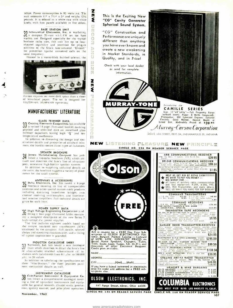
relays. Power consumption is 85 watts a.c. The unit measures 11" x 711" x 5" and weighs 1244 pounds. It is offered in a white case with white knobs with face panels available in five colors.
32
BASE STATION UNIT Lcronauticat Electronics, Inc. is marketing a compact 33 -watt v.h.t. -FM set for base
station use. Designed especially for the typical business radio user, this unit has up to four - channel capability and provision for plug -in addition of the firm's tone -actuated "Unicall" for protection against unwanted calls on the saine frequency.
Housed in a matte -black finished cabinet, the
station requires no nuue desk space th,lu a sheet of letterhead paper I he set is designed for 115 /230 -volt, 50 /60 1 m i le operation.
MANUFACTURERS' LITERATURE
GLASS TRIMMER DATA In Corning Electronic Components has available jj a revised 14 -page illustrated booklet covering physical and electrical data on metallized glass trimmer capacitors having high "Q" and low temperature coefficients.
In addition to discussing the design and con- struction details and properties of standard trim- mers, the booklet covers three types of inductors.
SPEAKER BROCHURE 3A Jensen Manufacturing Company has pub - r} fished atwo -color brochure (MX) which pic -
tures and describes the firm's line of ultra -com- pact, miniature high -fidelity speaker systems.
In addition to supplying technical details on the units. the brochure suggests a variety of place. ments for the small systems.
35
ANTENNAS d ACCESSORIES Delta Electronics, Inc. has issued a 4 -page brochure covering its line of transportable
antennas and other special custom -made products including operating impedance bridges, two- channel receiving nndticouplers, and transistor- ized monitor amplifiers. Full technical details are given for each item.
POWER SUPPLY DATA
36 High Vog Engineerinpo is feting altafour -pe age illustrated
g Cor folder
ration contaoG in
ing a complete description of the new Series 7 high -voltage d.c. power supplies.
The line includes eighteen models based on the unique insulated core transformers (ICT) developed by the company. Full details. selected design and operating characteristics. and a listing of typical applications is provided.
INDUCTOR CATALOGUE SHEET
31 ]ytroni(5, Inc. has issued a new catalogue sheet which ,Inscribes in detail the firm's line
of ultra -reliable shielded subminiature r.f. in- ductors with inductances from 0.1 Irby. to 180.000 alts. in 76 values.
In addition to tabulating the specifications on these "Wee-Doctors," the sheet provides perti- nent mechanical details as well.
INSTRUMENT CATALOGUE
3 o ° Cole- Parmer Instrument Sc Equipment Co. has issued a comprehensive catalogue cover-
ing a line of up -to -date instruments and equip- ment for general research. clinical study, produc- tion, quality control, and pilot -plant operation.
November, 1963
Z
sm
z m
1
This is the Exciting New "CG" Cavity Generator Spherical Sound System.
"CG" Construction and Performance are uniquely different than anything you have ever known and create a new awakening in Market Standards, in Quality, and in Price!
Check with your local dealer or send for complete
information.
NEW
CAMILLE SERIES Size: 11 "x8 "x414" -Full Frequency Range
(without boom). Power: 8 Watts (measured). Propagatior: 360 Spherical Degrees. Optional
Finishes: Oiled Walnut, Harvest Maple or Limed Oak. Moderately Priced at $39.95
iur-r ury -Car son Corporation 2424 E. 1,5th STREET, DEPT. 3A, INDIANAPOLIS 20, INDIANA
NEW CIRCLE NO. 138 ON READER SERVICE PAGE
rFill in coupon for a FREE One Year Sub- scription to OLSON ELECTRONICS Fan- tastic Bargain Packed Catalog - Unheard of LOW, LOW. DISCOUNT PRICES on Brand Name Speakers, Changers, Tubes, Tools, Stereo Amps, Tuners. CB, Hi Firs, and thousands of other Electronic Bargains. Credit plan available.
NAME
ADDRESS
CITY ZONE__-STATE -_ If you have a friend interested in electronics send his name and address for a FREE sub- scription also.
OLSON ELECTRONICS, INC.
6J1 Forge Street, Akron, Ohio 44308
CIRCLE NO. 140 ON READER SERVICE PAGE
ARB COMMUNICATIONS RECEIVER 51íg. by RCA. .1 I,.,i1,1.. il,.-. ki -.u NIr.
Excel. $29.95 BC -348 COMMUNICATIONS RECEIVER
,tat, ,nn ur. AND 1 , Mr. Ii-5u n Checked _ tu[-and In
guaranteed! $99.50 31'.B TUNING UNIT: For BC-375 Xlair. A
miniature warehouse of Parts! (teal 615.00 $1.95 value. Only
HELP US GET RID OF EXTRA CASHIIIIdl1,111 * WE WANT TO PAY YOU MONEY - BIG MONEY FOR ... * all types of military radio communicate and test equipment: R -388, R -390, PH' * GRC, TED Transmitter, and many othe- TELL US WHAT YOU HAVE FOR TOP DOLLl,I
COMMAND TRANSMITTERS 2.1.3 Me. New ,..$5.95 4 -5.:1 M.. New ...S6.95 3.4 Si,. Excel, ... 6.95 5.3 -7 Me. Less tubas
and xtal. 2.95 COMMAND RECEIVERS
1.5 -a Me. New 519.95 :1..; Ur. New ....$29.50 THE JUSTLY FAMOUS Q'SER. GOOD
CONDITION. SPECIAL $12.95 TRANSISTOR TAPE RECORDERS
So low in price -So high In value! Importer. close- out! These units record!, play bark, an,i a
ru Itntlt -In speaker. single .peed. voltage control b`. mp. with mike. batteries $9.95 Peg. 82i,.t :. Like new A excel. cond. end
, c'
s 5sE AS ABOVE. but less and mike. $3.95
GARAGE DOOR TRANSMITTER -RECEIVER This remote rontrol radio actuates garage door
motor (not steel led u, Small mpact transmitter mounts under dash. ̀a 12
`..o In Rersr 1
put t i 55-. no rye. Original price was 609.50.. Moieties schematic. $24.95 BRAND NEW!!! TEKTRONIX 513 -D OSCILLOSCOPE: Excel. i $295.00 checked out. Guar. close-Out! BC -376H 75 MC. MARKER BEACON TEST
OSCILLATOR: Excel. Checked nut. Guar. $99.50 anteed. F.B. for aircraft servicing TS -175/U FREQUENCY METER: 85 -10nn 5h.
Excel. Cond. Checked out. Guarantra,l.si 39.50 A buv of the month! only PR5.3 MINE DETECTOR: This Is the hi i $39.95 I1,5:1 model. Excel.
COLLINS ART -13 RADIO TRANSMITTER E2 -1K Sir. Im,
o
W. output. This Is the famous one! xcellent condition. A terrific $49.95 ,.,,v at n,l, ,.,,m, t , ,,,,ITI,uN $39.95
HEADSET & MIKE BARGAINS (15.23 HEADSET: Loom ohms. New S 4.95 NS -33 HEADSET: mil, ohms. Brand new . S 5.95 T -17D CARBON MI : Brand new ...5 9.95 RS -38 CARBON MIKE: Wilh coil cord and t'1..nA Plug. grand new and bargain buy! ....5 9.95
COLUMBIA ELECTRONICS 4365 WEST PICO BLVD. LOS ANGELES 19, CALIF.
CIRCLE NO. 108 ON READER SERVICE PAGE 107
www.americanradiohistory.com
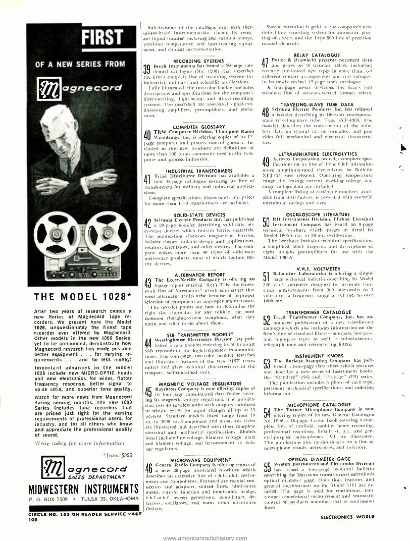
THE MODEL 1028* After two years of research comes a
new Series of Magnecord tape re- corders. We present here the Model 1028, unquestionably the finest tape rscorder ever offered by Magnecord. Other models in the new 1000 Series, yet to be announced, demonstrate how Magnecord research has made possible better equipment . for varying re- quirements . . . and for less money!
Important advances in the model 1028 include new MICRO -OPTIC heads and new electronics for wider, flatter frequency response, better signal to nose ratio, and superior tone quality.
Watch for more news from Magnecord during coming months. The new 1000 Series includes tape recorders that are priced just right for the varying requirements of professional users, for industry, and for all others who know and appreciate the professional quality of sound.
lVrite today for more information
*front $995
agnecord SALES DEPARTMENT
m MIDWESTERN INSTRUMENTS P. 0. BOX 7509 TULSA 35, OKLAHOMA
CIRCLE NO. 163 ON READER SERVICE PAGE 108
Sub -div': s of the catalogue deal with ther- mistor -based instrumentation. chemically resist- ant liquid transfer, metering and vacuum pumps, precision temperature and heat -treating equip- ment, and clinical instrumentation.
39
RECORDING SYSTEMS Brush Instruments has issued a 20 -page con- densed catalogue (No. 1200) that describes
t he firm's complete line of recording systems for industrial, military. and scientific applications.
Fully illustrated. the two -color booklet includes descriptions and specifications for the company's direct- writing. light -beam, and direct -recording systems. Also described arc associated signal -con-
ditioning amplifiers, preamplifiers, and enclo- s u res.
COMPUTER GLOSSARY
40 i
D ivifsfeiorinn,
g T
cI opieps f Ramo its I2-
page computer :und process control glossary. In- cluded in this new brochure are definitions of more than 200 terms commonly used in the com- puter and process industries.
41
INDUSTRIAL TRANSFORMERS Triad Distributor Division has available a
new 48 -page catalogue covering its line of transformers for military and industrial applica- t ions.
Complete specifications. dimensions. and prices
for more than II50 transformers are included.
42
SOLID -STATE DEVICES Sylvania Electric Products Inc. has published a 28 -page bnxtklet describing solid -state mi-
crowave devices which contain ferrite materials. The publication discusses magnetism. ferrites, isolator theory, isolator design and applications, rotators. circulators. and other devices. The com-
pany makes more than 80 types of solid -state
microwave products. most of which contain fer- rite devices.
43
ALTERNATOR REPORT The Lecce- Neville Company is offering an
8 -page report entitled "Let's Take the Guess-
work Out of Alternators" which emphasizes that most alternator faults arise because of improper selection of equipment or improper maintenance.
The booklet points out how to determine the
right size alternator for any vehicle, the most
common charging -system symptoms, what they mean and what to do about them.
SSB TRANSMITTER BOOKLET
44 N'estinghnuse Electronics Division has pub - lishcd a new booklet covering its 5i0- kilowatt
Still transmitter for high -frequency communica- tions. The four -page. two -color booklet describes
and illustrates features of the type \IST trans- mitter and gives technical characteristics of the compact, self -contained unit.
MAGNETIC VOLTAGE REGULATORS
45 Raytheon Company is now offering copies of its four -page consolidated data folder cover-
ing its magnetic voltage regulators. The publica- tion lists 40 tubeless units with outputs stabilized to within ±I% for input changes of up to 1:i
percent. Standard models listed range from I(1
va. to 3000 va. Component and apparatus styles
are illustrated and described with their complete electrical and mechanical specifications. Models listed include line voltage. filament voltage. plate and filament voltage, and ferroresonant a.c. volt- age regulators.
46
MICROWAVE EQUIPMENT General Radio Company is offering copies of a new 20 -page illustrated brochure which
describes an extensive line of v.h.f.- u.h.f. instru- ments and components. Featured arc coaxial con-
nectors and adapters. slotted lines. admittance meter, transfer- function and immittance bridge, v.h.f.- u.h.f. sweep generators. modulators, de-
tectors. oscillators, and many other microwave designs.
Special attention is paid to the company's new slotted -line recording system for automatic plot- ting of v.s.is e. and the Type a 900 line of precision coaxial elements.
41
RELAY CATALOGUE Potter & Br field presents pertinent data and prices on 50 standard relays, including
recently announced new types in more than 530 different contact arrangements and coil voltages. in its newly revised 12 -page stock catalogue.
A four -page insert describes the firm's full standard line of mercury -wetted contact relays.
TRAVELING -WAVE TUBE DATA
48 Stivania Cie( tris Products Inn. has released a booklet describing its loo -wain cnntinuouc-
w-ave traveling -wave tube. Type SI! -1369. The booklet describes the construction of the title, lists data on typical r.f. performance. and pro- vides full mechanical and electrical characteris- tics.
ULTRAMINIATURE ELECTROLYTICS
49 Aerovox Corpora ' provides cplue sp
ifications Cor on its line of Type CRE
om ltraminite
ec- -
attire aluminum -cased electrolytics in Bulletin NPJ -124 just released. Operating temperature range, d.c. leakage current. working soltage. and surge voltage data are included.
A complete listing of catalogue numbers. avail- able from distributors, is provided with essential microfarad ratings and sizes.
50
OSCILLOSCOPE LITERATURE RD lnstrumends Division, Hickok Electrical Instrument Company has issued an 8 -page
technical brochure which covers in detail its Model 1805A d.c. to 30 -mc. oscilloscope.
The brochure includes technical specifications. a simplified block diagram, and descriptions of eight plug -in preamplifiers for use with the Model 1805A.
51
V.H.F. VOLTMETER Ballantine Laboratories k offering a single - page technical bulletin describing its Model
340 v.h.f. voltmeter designed for accurate true - r.m.s. measurements from 300 microvolts to 3
volts over a frequency range of 0.1 mc. to over 1000 mc.
TRANSFORMER CATALOGUE
52 Freed Transformer Company, Inc. Iras an- pounced publication of a new transformer
catalogue which also includes information on the firm's line of standard filters- bandpass, low -pass,
and high -pass types as well as subminiarues, telegraph tone and telemetering filters.
INSTRUMENT KNOBS
53 The Buckeye Stamping Company has pub- lished a four -page data sheet which pictures
and describes a new series of instrument knobs. the "Standard" (SS) and "Prestige" (PS) series.
The publication includes a photo of each type, pertinent mechanical specifications. and ordering information.
54
MICROPHONE CATALOGUE The Turner Microphone C parry is now offering copies of its new General Catalogue
No. 1008. a 16 -page. 4 -color hook covering a com- plete line of cardioid. mobile. home recording. professional recording, broadcast. p.a.. and gen-
eral- purpose microphones. All are illustrated. The publication also carries details on a line of microphone stands, accessories, and interiors.
55
OPTICAL DIAMETER GAGE Weston Instruments and Electronics Division has issued a four-page technical bulletin
describing the Daystrom transistorized microlimit optical diameter gage. opera ' . features. and general specifications on the Model 5111 are de-
tailed. The gage is used for continuous, non - contact dimensional measurement and automatic control of products manufactured in continuous form.
ELECTRONICS WORLD
www.americanradiohistory.com
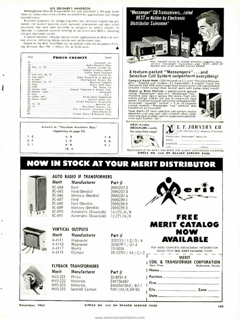
SCR DESIGNER'S HANDBOOK Westinghouse Electric Corpora has just published a 389 -page hand-
book on silicon controlled rectifier characteristics, applications, and design considerations.
Produced especially for design engineers and technical supporting per- sonnel, the manual contains much technical information and data which previously had only been available to designers by special request. In addition, it contains material relating to the firm's new SCR's. including the gate controlled switch.
A special detailed I Iii-page section covers applications of SCR's in vari- ous circuits, including design details and performance data.
Copies of the SCR Handbook can be ordered from the company's Print- ing Division, Box 398, 'Trafford, Pa. at $2.00 each. .
Pogo PIIOTO I'REDITS Credit
22 Acoustech, Inc. 24 Audio Dynamics Corp. 28 (Fig. 1), 29 Douglas Aircraft Co. 28 Federal Aviation Agency 30 Collins Radio Company 32 (top left), 66, 67 Hughes Aircraft Co. 32 (top right) Radio Corporation of Americo 32 (center) Westinghouse Electric Co. 32 (bottom), 47, 72 Raytheon Company 33 (top) Sperry Rand Corp. 33 (left) The Telcan Co. 33 (bottom left) General Telephone 6 Electric Corp. 33 (bottom right) Honeywell 36 pop) E C I. 36 (center left) Allied Radio Corporation 36 (center right) Business Radio, Inc. 39 Jerrold Electronics Corporation 50, 51, 52 Motorola Inc. 53, 54 NonLinear Systems, Inc. 86 Eico Electronic Instrument Corp. B7 Delta Electronics 88 Pioneer Electric & Research Corp.
1. C
Answers to "Television Waveform Quiz" (Appearing on page 95)
4. D 7. E
2. F 5. B 8. G
3. I 6. H 9. J
10. A
"Messenger " CB Transceivers...rated BEST in Nation by Electronic
Distributor Salesmen'
rrrrrrrrrrr ,- `utJ1IW'` New impartial survey by leading electronic magazine shows
Johnson "Messenger" Transceivers rated -BEST--BEST BY NEARLY 50% OVER SECOND CHOICE BRAND.
4 feature -packed "Messengers" ... and Selective Call System outperform everything! Compact, Hand -Held -100 milliwatt or 11/2 watt "Personal Messen- gers". Rugged and reliable-1 1 transistors, 4 diodes! Twice the sensitivity and 40% more range than similar units with conventional circuitry -more output than similar units with same rated inputs! Mobile or Base Stations - performance proved Viking "Messenger" and new "Messenger Two ". Punches your signal across the miles -high effi- ciency design makes full use of maximum legal power. Excellent receiver sensitivity and selectivity. Automatic "squelch" control - 5 or 10 channel crystal control -"Messenger Two" receiver also tunable on all channels! Tone Alert -37 tone selective call system mutes speakers until one unit calls another -then auto - matically your stations receive audio note and indi- cator light flashes "On ".
maismrs-
NEW! 4 -color BROCHURE -write for your free copy!
t-
,' .
E. F. JOHNSO% f.0' 1102 10th Ave. S.W., Waseca, Minnesota
Please rush -Messenger" details to:
ADDRREE SS
CITY STATE of the world's most widely used personal communications transmitters,
CIRCLE NO. 1es ON READER SERVICE PAGE
NOW IN STOCK AT YOUR MERIT DISTRIBUTOR
T 1
AUTO RADIO IF TRANSFORMERS
Merit Manufacturer BC -684 Ford BC -685 Ford (Bendix) BC -686 Mercury (Bendix) BC -687 Ford BC -688 Ford (Bendix) BC -689 Mercury (Bendix) BC -690 Automatic (Riverside) BC -691 Automatic (Riverside)
VERTICAL OUTPUTS
Merit Manufacturer A -4111 Magnavox A -4113 Magnavox A -4117 Muntz A -4119 Olympic
FLYBACK TRANSFORMERS
Merit Manufacturer HVO-221 HVO-222 HVO-223 HVO-225
Philco Motorola Motorola Setchell Carlson
Part # 2090237 -2 2090237 -3 2090237 -4 2090239 -1
2090239 -2 2090239 -3 14 -270/A /X 12 -271 /A /X
Part # 320255/-1-2/-3/-4 320079 -1 / -3/ -4 TO -0056 TR -25791 / -1 A / -C / -2
Part # 32 -8951 -4 24K736487 24D65410A2/ -B / -1
TWF- 110 /X,WF -90
November, 1963
FREE MERIT CATALOG
NOW AVAILABLE
FOR MORE COMPLETE REPLACEMENT INFORMATION ORDER YOUR FREE MERIT CATALOG TODAY r MERIT
I COIL & TRANSFORMER CORPORATION Merit Plaza Hollywood, Florida
I Name
I Position
Firm
City Zone
State
CIRCLE NO. 156 ON READER SERVICE PAGE 109
www.americanradiohistory.com
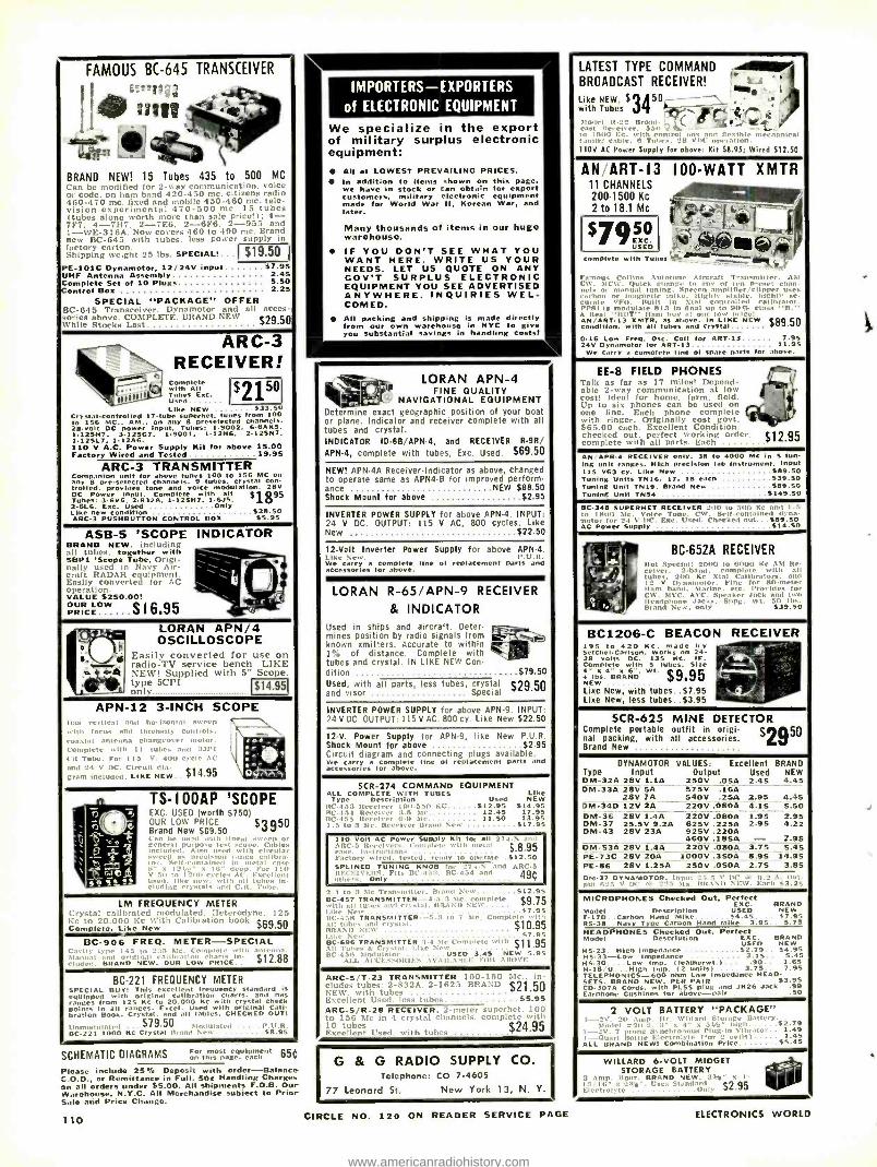
FAMOUS BC -645 TRANSCEIVER
'.tot. :III, . ' 4 .gige 1 .
f
w1 `h
C
BRAND NEW! 15 Tubes 435 to 500 MC ('an be modified for 2 -any communication. vi, or code. on ham band 420 -450 mc. citizens ra 460 -470 mc. fixed and mobile 430 -460 mc. tv.v- vision experimental 470 -500 mc. 15 tubes (tubes alone worth more than sale price! 1 ; 4- 7F7. 4 -7117, 2 -7E6. 2 -6F6. 2 -955 and I- WE -316A. Now covers 460 to 490 mc. Brand new BC -645 with tubes, less power supply In I:tctory carton. shipping weight 25 lbs. SPECIAL!.. $11 9.50
PE -101C Dynamotor, 12/24V input $7.95 UHF Antenna Assembly 2.45 Complete Set of 10 Plugs 5.50
ontrol Box 2.25 SPECIAL "PACKAGE" OFFER
BC -645 Transceiver. Dynamotor and all !,
sories above. COMPLETE, BRAND NEW 529.50 While Stocks List
ARC -3 -, RECEIVER!
r Complete
N 1 71"."2.. Used. 250I 1
1
Like NEW ....... .533.50 Crystal -Controlled l7 -tube superhet. tunes from 100 to 156 MC.. AM.. on any 8 presele ed channels. 28 -volt DC power Input. Tubes: 1 -9002. 6.6AK5. 1. 12áN7, 3.12507. 1.9001 1.12146. 2.125147. 1.12SL7, 1.1246. 110 V A.C. Power Supply Nit for above 15.00 Factory Wired and Tested 19.95
ARC -3 TRANSMITTER Companion unit for above tunes 100 to 156 MC on any 8 preselected Channels. 9 tubes. Crystai con- trolled. provides tone and voice modulation. 28v DC Power input. Complete with all 51 095 Tubes: 3 -6V6. 2832A. 1.125147. 1.615. ao 2.6L6. Exc. Used Only Like new condition ....................$28.50 ARC -3 PUSHBUTTON CONTROL BOX $5.95
ASB -5 'SCOPE INDICATOR BRAND NEW including all tubes. with - -` WW1 'Scope Tube. Origi- nally used in Air-
RADAR equipment. craft '
Easily converted for AC operation. VALUE $250.00! l(ì OUR LOW $
1 6.95 - PRICE
,_1 : -40
e^ . -4
LORAN APN /4 OSCILLOSCOPE
Easily converted for use on radio -TV service bench. LIKE NEW! Supplied with 5" Scope. type 5CPI 1$14.951 only
APN -12 3 -INCH SCOPE l las vertical and horioontal sweep
.. till focus and Intensity controls. ui ins antenna changeos cr motor.
mplete with II tubes and 3.111 . It Tube. For 115 V. 4(1(1 cycle AC n,tl 24 V DC. Circuit dia. ,t r. . .:m Included. LIKE NEW. $14.`75
r Pé .
e s..'a pf'r'rat
TS -IOOAP 'SCOPE EXC. USED (worth $750)
A..
. q
OUR LOW PRICE $3950 Brand New $69.50 t . be U. with linear sweep n
-rd purpose hest scone.
Cattle ..luied. .l mist ,ith crcul ep as precision range coup':,
_1_1 x deep. For r JsP
ÌIf ram al t in metal
d, lli n ti 9, SS eh ad. like new. with
al l tu1..
tiding crystals find C.II. 7'e,
LM FREQUENCY METER tal calibrated modulated. Heterodyne, 125 :c to 20,000 Kc With Calibration book $69.50 Complete, Like New
RC -90G FREQ. METER -SPECIAL ß
I. BRAND NEW. OUR LOW PRICE-. $12.88
BC -221 FREQUENCY METER SPECIAL BUY! This excellent frequency standard Is equipped with original Calibration charts. and has ranges from 125 Kc to 20.000 Kc with Crystal check points in all ranges. Excel. Used with original Cali- bration Book. Crystal. and all tables. CHECKED OUT!
l'nnowlulatet! . .$79.50 Modulated .......V.R. BC -221 1000 Kc Crystal Brand New $8.95
SCHEMATIC DIAGRAMS ó ,Iren s pa:e.a.an'hnt 65(
Please include 25% Deposit with order -Balance C.O.D., or Remittance in Full. 50e Handling Charges an all orders under $5.00. All shipments F.O.B. Our Warehouse. N.Y.C. All Merchandise subject to Prior Sale and Price Change.
110
IMPORTERS -EXPORTERS
of ELECTRONIC EQUIPMENT
We specialize in the export of military surplus electronic equipment:
All at LOWEST PREVAILING PRICES. In addition to items shown on this page, we have in stock or can obtain for export customers. military electronic equipment made for World War 11, Korean War. and later.
Many thousands of items in our huge warehouse. IF YOU DON'T SEE WHAT YOU WANT HERE. WRITE US YOUR NEEDS. LET US QUOTE ON ANY GOV'T SURPLUS ELECTRONIC EQUIPMENT YOU SEE ADVERTISED ANYWHERE. INQUIRIES WEL- COMED. All packing and shipping is made directly front own warehouse in NYC to giro you substantial savings in handling costs!
LORAN APN -4 AIM l FINE QUALITY
NAVIGATIONAL EQUIPMENT L ' "nine exact geographic position of your boa' Cr pidne. Indicator and receiver complete with all tubes and crystal. INDICATOR 106B /APN -4, and RECEIVER R -98 APN -4, complete with tubes, Exc. Used. $69.50
NEW! APN -4A Receiver -Indicator as above, changers to operate same as APN4 -B for improved perform ance NEW $88.50 Shock Mount for above $2.95
INVERTER POWER SUPPLY for above APN -4. INPUT: 24 V DC. OUTPUT: 115 V AC, 800 cycles. Like New $22.50
12 -Volt Inverter Power Supply for above APN -: Like New. P.I. I. We carry a complete line of replacement parts and accessories for above.
LORAN R -65 /APN -9 RECEIVER
& INDICATOR Used in ships and aircraft. Deter- ri- mines position by radio signals from Geri known xmitters. Accurate to within 1% of distance. Complete with tubes and crystal. IN LIKE NEW Con- dition 579.50 Used, with all parts, less tubes, crystal $29.50 and visor Special
INVERTER POWER SUPPLY for above APN -9. INPUT: 24 V DC. OUTPUT: 115 V AC. 800 cy. Like New $22.50
12V. Power Supply for APN -9, like New P.U.R. Shock Mount for above $2.95 Circuit diagram and connecting plugs available. We carry a complete line of replacement parts and accessories for above.
SCR -274 COMMAND EQUIPMENT ALL COMPLETE WITH TUBES Like Type Description Us, -d NEW
.13:1 Receiver 111115SÚ KC ..... .512.95 514.95 454 Receiver 9 -0 51c .. 12.45 17.95 -455 Receiver 13-9 Mc 1i.50 13.95
to 3 Me. ReCCIVCe Brand New $17.95
110 Volt AC Power Supply Kit for all 274 N and NBC-5 Receivers. Complete with metal $.85
FacInstructions tory wired. tented. ready to operate .612.50
SPLINED TUNING KNOB I.. 27 and ARC- - ItECEIVF:Its l . 1: 1-: I:.- t7 t eI 49( t iItrn. Only ... `r
1 In :I `.1. 'I In I::l \. - $12.95 IiC -457 Tit 555M I Tri Ii -1.5.:1 iiC. complete $9,75
. L.. Illt. \ND NFW 57.95
rlt .^.sr.,lrrt it -5.3 to 7 Mc. Complete ith $10.95 67.95
$11.95 í15F0 3.4S NEW 5.95
::1-. \ \ -1. 1.,1: \ II, IVF.
ARC -5, T.23 TRANSMITTER 100 -150 Mc., in- cludes tubes: 2 -832A. 2- 1623. BRAND $21.50 NEW. with tubes Excellent Used. .. tubes $5.95 ARC- S /R -28 RECEIVER, 2 -meter superhet, 1:'" to 156 Mc in .1 "II channels. complete n.' 10 tubes $24.95 Excellent t'< -
G & G RADIO SUPPLY CO. Telephone: CO 7 -4605
77 Leonard St. New Yolk 13, N. Y.
CIRCLE NO. 120 ON READER SERVICE PAGE
LATEST TYPE COMMAND BROADCAST RECEIVER! f` t'A Like NEW. SA511 .-
L
with Tubes \Inn Broad' /v..... :st 1: 550 /
them I.t' with control box and next.,. ,..,,,,sash_. 'onin2 ratite. a Tubes. 28 Vitt' operation 110V AC Power Supply for above: Kit 58.95; Wired 512.50
AN ART -I3 100 -WATT 11 CHANNELS 200-1500 Kc ,'.,«)'r-..
XMTR
' $79 só
si11
No . o Iw+rr+'..r. co nnlete w,th Tuns
Famous Collins Autotune Aircraft Tranxmltter. As: I W. MCW. Quick change to any of ten preset chap netn or mnnual tuning. Speech amplifier' clipper use - nrbon or Iagnetic mike. Highly stable. highly n
curate 5 Ft1. Built In Xtal controlled rnllbrntoi sI Is modulate 815 In final up to 90,1. class 'it.'
s heal '110T Ham buy at o
t
r low mice' condittiion . with allltubes andC,y tallE NEW 889.50
0.16 Low Freq. Osc. Coil for ART -13 7.95 24V Dynamotor for ART13 11.95
We carry ., complete line of snare parts for ahoye.
EE -8 FIELD PHONES Talk as far as 17 miles! Depend- able 2 -way communication at low ,ost! Ideal for home, farm, field. Up to six phones can be used on one line. Each phone complete la I .r?
with ringer. Originally cost govt. 565.00 each. Excellent Condition. checked out. perfect working order. $12.95 complete With all parts. Each
AN'APR4 RECEIVER only. 38 to 4000 MC in 5 tun- ing unit ranges. High precision lab instrument. Input 115 V63 Cy. Like New $89.50 Tuning Units TN16. 17, 18 each $39.50 Tuning Unit TN19. Brand New $89.30 roning Unit 71454 5149.50
fir 148 SUPERHET RECEIVER 2011 t0 5110 Kc and 1.5 - \Ic. Voice Tune, CW. Self- contained 11na-
_'1 V Dt'. Exc. Used. Checked out 589.30 aC e.,... r Supply $14.30'
BC 652A RECEIVER 'lot Special; 21100 to tiU011 Kc AM Re 'elver. 2 -hand. complete with all
% 1 tubes. 2011 Kc Xtol Calibrators, and 12 V Dynamotor. Fine for Kit -meter
!' Ham band. Marine. te. Provides for t.W. StVC. AVC. Speaker .lack and two
1 I. Headphone Jacks. Shpg. it't 5t I1, -. of Brand New. only $39.50
BC1206 -C BEACON RECEIVER 195 to 420 Kc. made by sr.. ,. . .r-. .
St'tchelCarlson. Works on 24. 28 volts DC. 135 KC. IF. Complete with S tubes. Size 6 " x 4' x ". Wt. $9.95 4 lbs. BRAND NEW Like New, with tubes..$7.95 Q/ 4
Like New, less tubes..$3.95
SCR -625 MINE DETECTOR Complete portable outfit in origi- $2950 nal packing, with all accessories L Brand New
DYNAMOTOR VALUES: Excellent BRAND Type Input Output Used NEW DM -32A 28V 1.1A 250V .05A 2.45 4.45 DM -33A 28V SA 575V .16A
28V 7A 540V .25A 2.95 4.45 0M -340 12V 2A 220V .080A 4.15 5.50 0M -36 28V 1.4A 220V .080A 1.95 2.95 DM -37 25.5V 9.2A 62SV .22SA 2.95 4.22 DM -43 28V 23A 925V .220A
460V .185A - 7.95 DM -53A 28V 1.4A 220V .080A 3.75 5.45 PE -73C 28V 20A 1000V .350A 8.95 14.95 PE -86 28V 1.25A 250V .050A 2.75 3.85
-. S V Da 7 5 DV Ntic O1 R.
S iput ^R\ND sI
MICROPHONES Checked Out, Perfect EXC. BRAND
Model Description USED NEW T- 17D..Carbon Hand Mike.. . ..$4.45 57.95 05.38 .Navy Type Carbon Hand Mike 3.95 5.75 HEADPHONES Checked Out. Perfect Model Description EXC. BRAND
USED NEW 14S -23 High Impedance 52.79.. $4.95 H5 -33 -Low Impedance .... 3.15.. 5.45 HS 30. ...LOW Imp. ifeatherwt.) .90.. 1.65 H 16' U. .High Imp. (2 units) 3.75.. 7.95 TELEPHONICS -600 ohm Low Impedance HEAD- SETS. BRAND NEW. PER PAIR $3.95 CD307A Cords. with PL55 plug and JK26 Jack .99 Earphone Cushions for above -pair.... .50
2 VOLT BATTERY "PACKAGE" 1- .1 I' tir. Willard Storage Battery.
I -_s'. : nclroitte Plug-in llbralor 1.49 no
I -Quart '. E.
NEW! ion' Y cells) 1.45
ALL BRAND NEW! Combination Price SS.45
WILLARD 6 -VOLT MIDGET O STORAGE BATTERY
D ,7,
BRAND NEW. 3," 1- f Une. St.m!:,I $2.95
ELECTRONICS WORLD
www.americanradiohistory.com
ELECTRONICS MARKET PLACE RATE: 60C per word. Minimum 10 words. January issue closes November 5th. Send order and remittance to:
ELECTRONICS ENGINEERING
AND INSTRUCTION USED Correspondence Courses and Books sold and rented. Money back guarantee. Catalog Free. (Courses Bought.) Lee Mountain, Pisgah, Alabama. ELECTRONICS! Associate degree -29 months. Techni- cians, field engineers, specialists in communications, missiles, computers, radar, automation. Start February, September. Valparaiso Technical Institute, Dept. N. Valparaiso, Indiana. FCC LICENSE in six weeks. First class radio telephone. Results guaranteed. Elkins Radio School, 2603C, In- wood. Dallas. Texas. HIGHLY -effective home study review for FCC commer- cial phone exams. Free literature! Wallace Cook, Box 10634, Jackson 9, Miss. ENGINEERING and Art Degrees earned through home study. Electronics, mechanical, liberal arts, major ac- counting. When writing specify course desired. Pacific International College of Arts & Sciences, primarily a correspondence school. Resident classes also available. 5719 -C Santa Monica Blvd., Hollywood 38, California.
FOR SALE GOVERNMENT Surplus Receivers, Transmitters, Snoop erscopes, Parabolic Reflectors, Picture Catalog 100. Meshna, Nahant, Mass. INVESTIGATORS, free brochure, latest subminiature electronic listening devices, Ace Electronics, 115001 NW 7th Ave., Miami 50, Florida. MILITARY Discount-Name Brands Free Recording Tape and Stereo Handbook. Include Rank and Serial Num- ber. Electronics International, Inc , Box 3066, Char- lottesville, Virginia. Save dollars on radio, TV- tubes, parts at less than manufacturer's cost. 100% guaranteed. No rebrands, pulls. Request Bargain Bulletin. United Radio 1000 -W, Newark, N.J.
CANADIANS -Giant Surplus Bargain Packed Catalogs. Electronics, Hi -Fi, Shortwave. Amateur, Citizens Radio. Rush $1.00 (Refunded). ETCO. Dept. Z, 464 McGill, Montreal, Canada. TRANSISTORIZED Products importers catalog, $1.00. Intercontinental, CPO 1717, Tokyo, Japan. "LISTEN -in -coil" picks up any telephone conversation in vicinity. No connection to telephone necessary. Easily concealed. $2.98 complete. Consolidated Acous- tics, 1302Y Washington St., Hoboken, N.J. CONVERT any television to sensitive, big- screen oscil- loscope. Only minor changes required. No electronic experience necessary. Illustrated plans, $2.00. Relco, Box 10563. Houston 18. Texas GARAGE Door Openers $60. Radio Controls. Sales. Service. Sefton, 8309 Fenton Street, Silver Spring, Maryland. JUST starting in TV service? Write for free 32 page catalog of service order books, invoices, job tickets, phone message books. statements and file systems. Oelrich Publications, 6556 W. Higgins Rd. Chicago, III. 60656. SAVE Money -Free catalog: Photography, Tape Re- corder, Hi Fidelity. Electronics tools, Wholesale Radio & Camera Company, Box 3085, Phila. 50, Pennsylvania. OHM'S law never forgotten with copyrighted tool. $2.00 Postpaid. Beck Radio, 6323 South Dale Mabry, Tampa, Florida 33611.
TUBES TUBES -TV, Radio, Transmitting And Industrial Types At Sensibly Low Prices. New, Guaranteed, 1st Qual- ity, Top Name Brands Only. Write For Free Catalog or Call WAlker 5 -7000, Barry Electronics Corp., 512 Broadway, New York 12N, N. Y.
BEFORE you buy receiving tubes, test equipment, Hi -fi components, kits, parts, etc.... send for your giant free Zalytron current catalog, featuring Standard brand tubes: RCA, GE. etc. -all brand new premium quality individually boxed. One year guarantee -all at biggest discounts in America! We serve professional service- men, hobbyists, experimenters, engineers, technicians. Why pay more? Zalytron Tube Corp., 461 Jericho Turn- pike, Mineola, N. Y.
FREE Catalog -name brand tubes 65% discount. phono needles 80% or more discount, phono cartridges. picture tubes 75C inch, parts. parts kits, silicon and selenium rectifiers transmitting tubes, 7" T.V. test tube $6.99, imported batteries, tube testers etc. Want to swap or sell tube inventory? Send us your offering. Arcturus Electronics Corp., Dept. Z.D., 502 22nd St., Union City, N.J.
November, 1963
WANTED
CASH Paid! Sell your surplus electronic tubes. Want unused, Clean radio and TV receiving, transmitting special purpose, Magnetrons, Klystrons, broadcast types. Want military and commercial lab test equip- ment such as G.R.H.P., AN UPM prefix. Also want commercial Ham Receivers and Transmitters. For a Fair Deal write: Barry Electronics Corp., 512 Broad- way, New York 12. N. Y. (Walker 5- 7000).
INVENTORS. We will develop, help sell your idea or invention, patented or unpatented. Our national manu- facturer clients are urgently seeking new items for out- right cash sale or royalties. Financial assistance avail- able. 10 years proven performance. For free informa- tion, write Dept. 42, Wall Street Invention Brokerage, 79 Wall Street, New York 5, N.Y.
QUICKSILVER. Platinum, Silver, Gold. Ores Analyzed. Free Circular. Mercury Terminal, Norwood, Mass. ARMY Sets or Parts- GRC- PRC- FRR /URR- TCC -5B -SCR--Send Listings -Quick Cash. Anker Electronics, 1617 So Main St., Box 26, Wilkes- Barre, Pa.
TAPE AND RECORDERS TAPE Recorders, HI-FI Components. Sleep Learning Equipment, Tapes. Unusual Values. Free Catalog. Dress - ner, 1523 EW Jericho Turnpike, New Hyde Park 10, N.Y.
RENT Stereo Tapes -over 2,500 Different -all major labels -free brochure. Stereo -Parti, 1616 -E. W. Ter- race Way, Santa Rosa, California.
SELF -Hypnosis. New concept teaches you quickly by tape or LP- record. Free literature. McKinley Publishers, Dept. T6, Box 3038. San Bernardino. California. SAVE 30% Stereo music on tape. Free bargain catalog/ blank tape recorders norelco speakers. Saxitone, 1776 Columbia Road, Washington, D.C.
RECORDING Tapes. Free sample. Mail 25C (Handling). Towers, Lafayette Hill, Penna. TAPE Recorder Sale. Latest models $10.00 above cost. Arkey Sales, 22 -21 Riverside Avenue, Medford 55, Massachusetts. RECORDING tape highest quality 1800' Mylar 7" reel 10 for $18.50 postpaid. Moneyback guarantee. Lowest quotes: all components, recorders. Pofe Electronics, 1716 Northfield, Muncie, Indiana, 47304.
HIGH -FIDELITY HI -Fl Components, tape recorders at guaranteed "We Will Not Be Undersold" prices. All brands in stock. 15 -day money back guarantee. 2 year warranty. Write your requirements for quotation. No Catalog. Hi- Fidelity Center 1797L 1st Ave., New York 28, N.Y. RECORDERS, Components! Free wholesale catalogue! Carston. 125 -R. East 88. N.Y.C. 28. DISGUSTED with "Hi" Hi -Fi Prices? Unusual Dis- counts On Your High Fidelity Requirements. Write. Key Electronics, 120 Liberty St., New York 6, N. Y. Dí6.4191. LOW, LOW quotes: all components and recorders. Hi -Fi, Roslyn 9. Penna.
WRITE for lowest quotations, components, recorders. No Catalogs Hi- Fidelity Supply, 2817 -GC Third, New York City 55.
"FM /Q" Metropolitan Broadband Antenna, the finest compact yagi made, completely rustproof, only $14.95 prepaid. FM Book with station directory 30e. FM /Q, Wethersfield, Connecticut. LOOKING for really good sound? We don't sell com- ponents, but we do offer an inexpensive consulting service to help you solve your component selection and installation problems. For details, write to V. diZerega, 66 N. Middle Road, Media, Pa.
REPAIRS AND SERVICING
TV Tuners Rebuilt and Aligned per manufacturers spe- cification. Only $9.50. Any Make UHF or VHF. We ship COD Ninety day written guarantee. Ship complete with tuoes or write for free mailing kit and dealer brochure. JW Electronics. Box 51B. Bloomington. Indiana. METERS -Multimeters Repaired and Calibrated. Free estimates -Catalog. Bigelow Electronics, Box 71F, Bluffton. Ohio. SPEAKERS rebuilt. All types. One day service. Westen, 5230 14th, Lubbock, Texas.
ELECTRONICS WORLD, One Park Ave., N. Y. C. 16, N. Y.
TV Tuners Rebuilt and Aligned to Specifications. Guaranteed All Makes. One Price. $9.50 Complete. Plus Shipping. Valley Tuners, 5641 -B Cahuenga, North Hollywood, Calif.
RECORDS RARE 78's. State Category. Write Record -Lists, P.O. Box 2122, Riverside, Calif.
PATENTS PATENT Searches, $6.00! Free "Invention Record " / Information. Miss Hayward, 1029 Vermont, Washing- ton 5. D.C.
LICENSE available: Thermostats -Small Temperature responsive switch devices for supervising and regu- lating fixed operational temperatures (US- Patent). More information by Kapazitatenvermittlung Dr. Raabe, Obernhainer Str. 10, 6 Frankfurt /M., Germany West.
BUSINESS OPPORTUNITIES
HIGH income in your own wired -music business. Free details! CSOE, Box 10634, Jackson 9, Miss.
SHOPPING GUIDE CLASSIFIED
A HANDY GUIDE TO PRODUCTS, NOT NECESSARILY ELECTRONIC, BUT OF WIDE GENERAL INTEREST.
BOOKS AUTHORS! Learn how to nave your book published, promoted, distributed. FREE booklet "ZD," Vantage, 120 West 31 St., New York I WANTED: Short stories, books, articles, plays of all descriptions for sale to publishers, producers. Free literature! Literary Agent Mead, Dept. 39A, 915 Broad- way, N. Y. C. 10.
GOVERNMENT SURPLUS
GOVERNMENT Surplus Direct From Government. Jeeps $264.00. Radios $2.53, Typical Prices. Guns, Type- writers, Cameras, Tools, Thousands More. Amazing Low Prices. How, Where To Purchase, Merchandise Available, Etc., Only $1.00 To: Surplus, P.O. Box 50512, Dept. R. New Orleans 50. Louisiana. JEEPS -$111.68, Typewriters- $4.15, Receivers- $5.65, Televisions, Recorders, Oscilloscopes, Multimeters. Typical Government Surplus Prices. Exciting Details Free. Enterprises, Box 402 -85, Jamaica 30, New York. JEEPS $178, Airplanes $159, Boats $7.88, generators, $2.68, typewriters $8.79, are typical government sur- plus sale prices. Buy 10,001 items wholesale direct. Full details, 607 locations, procedure only $1.00. Sur- plus Box 177 -CI Abbottstown, Penna. JEEPS $111.68, Boats $6.18, Airplanes, Electronics Equipment, Typewriters, thousands more, typically at up to 98% savings. Complete information $1.00. Sur- plus Service, Box 820, Holland 11, Michigan. GOVERNMENT Surplus Sales Bulletin - "Directory - Procedure" - 504 - Industrial, Box 770(A), Hoboken, N.J.
SURPLUS Direct From Government; Information Booklet & Depot Directory Only $1.00. Ramco, Box 356 -E, No. Hollywood, California.
STAMPS AND COINS TERRIFIC Stamp Bargain! Israel -Iceland -San Marino - plus triangle set -Plus Antigua -Borneo -Virgin- Scouts. Congo- Russia -Plus large stamp book -all four offers free -Send 10C for mailing cost. Empire Stamp Cor- poration, Dept. 22, Toronto, Canada. 20 Different Commemoratives 1893 up 10C. U. S. Ap- provals, K & B, Box 70, Brooklyn 23, N. Y.
HELP WANTED EARN Extra money selling advertising book matches. Free Samples furnished. Matchcorp, Dept. MD -13, Chicago 32, Ill.
111
www.americanradiohistory.com
EMPLOYMENT INFORMATION
FOREIGN Employment. Construction, other work prof ects. Good paying overseas jobs with extra, travel expenses. Write only Foreign Service Bureau, Dept. D.
Bradenton Beach. Flonda
EDUCATIONAL OPPORTUNITIES
LEARN While Asleep, hypnotize with your recorder. phonograph. Astonishing details, sensational catalog free! Sleep- Learning Association, Box 24 -ZD, Olympia, Washington. LEARN while asleep. Remarkable, scientific. 92', ef- fective. Details free. ASR Foundation, Box 721, Dept.
z L.'ntucky.
PHOTOGRAPHY - FILM, EQUIPMENT, SERVICES
MEDICAL FILM -Adults only -"Childbirth," one reel, 8mm $7.50; 16mm $14.95. International W, Greenvale, L.I.. New York. SCIENCE Bargains- Request Free Giant Catalog "CJ" -144 pages -Astronomical Telescopes. Microscopes, Lenses, Binoculars, Kits. Parts. War surplus bargains. Edmund Scientific Co., Barrington, New Jersey.
BUSINESS OPPORTUNITIES
I Made $40,000.00 Year by Mail Order! Helped others make money! Start with $10.00- -Free Proof. Toney Box 3566 -íl. Oklahoma City 6, Oklahoma. MAKE Durable Building Plastic Easily. Waterproof, fire- proof, economical. Bays Laboratory, Cedaredge 8. Colorado. SONGS into $$$$$ -New, unknown. Songwriters. Song -
poets. Composers share $33 millions yearly. Any sub- ject, we collaborate. publish. promote. Largest firm information. appraisals Free. Send Nordyke Publishers, 6000 Sunset, Hollywood, California 3- 90028.
MISCELLANEOUS HYPNOTIZE Unnoticed, quickly, effortlessly, or refund! Thousands delighted! $2.00. Minter, Box 244 -D, Cedar -
burg. Wisconsin. WILD Labels, bumper strips! Strange, startling. un- conventional! Krazy Labels. Box 15 -H, Olympia, Wash- ington.
If you've recently changed your address or
plan to in the near future, be sure to notify
us of once. Place magazine address label
here and print your new address below.
NEW ADDRESS: NAME
PLEASE PRINT
ADDRESS
CITY_ _ ZONE_STATE
MAIL COPIES TO NEW ADDRESS STARTING
WITH - __ _ ISSUE.
If you have any other questions about your subscription be sure to include your magazine address label when writing us.
Mail to: ELECTRONICS WORLD, 434 So.
Wabash Avenue, Chicago 5, Illinois
112
ELECTRONICS WORLD NOVEMBER 1963
ADVERTISERS INDEX
READER
SERVICE NO. ADVERTISER PAGE NO.
READER
SERVICE NO. ADVERTISER PAGE NO.
104 AEC Laboratories, Inc. 16 166 McGee Radio Co. 100
164 ATR Electronics, Inc. 98 163 Magnecord Sales Department,
100 Advance Electronics 76 Midwestern Instruments 108
101 Allied Radio 61, 62 133 Massey Technical Institute 84
102 American Concertone, Inc. 81 134 Merit Coil & Transformer Corporation 109
American Institute of Engineering & Technology 106 Merrell Kits 72
103 Arcturus Electronics Corp. 64 135 Minnesota Mining &
Manufacturing Co. 1
136 Motorola Training Institute 105 105 B & K Manufacturing Co. 15 137 Multicore Sales Corp. 100 165 Blonder Tongue 83
169 Multicore Sales Corp. 94 106 Burstein -Applebee Co. 99 138 Murray- Carson Corporation 107
107 Cadre Industries, Inc. 24 National Radio Institute 79, 80 Capitol Radio Engineering
139 Nortronics 82 Institute, The 13
Channel Master Corp. 57, 58, 59
Cleveland Institute of Electronics .. 21 Oelrich Publications 99
108 Columbia Electronics 107 140 Olson Electronics, Inc. 107
109 Columbia Products Company 74
110 Commissioned Electronics, Inc. .. . 90 141 Palmer Electronics 94
Conar 101 142 Poly Paks 78
111 Concord Electronics 4
167 Cornell Electronics Co 102 RCA Electronic Components 112 Crown International 105 and Devices . FOURTH COVER, 87
RCA Institutes, Inc. 8, 9, 10, 11
113 Datak Corporation 14 R W Electronics 72
Dressner 99 Relco 74
159 Dual 25 143 Rider Publisher Inc., John F. 96
144 Roberts Electronics, Inc. 100
114 EICO Electronic Instrument Co., Inc. 26
115 Editors and Engineers, Ltd. 76 145 Sams & Co., Inc., Howard W. 93
116 Electro- Voice, Inc. ...SECOND COVER 146 Sams & Co., Inc., Howard W. 104
117 Electronic Chemical Corp. 90 110 Saxitone Tape Sales 90
147 Schober Organ Corporation, The 97
118 Fair Radio Sales 106 148 Scott Inc., H. H. 2
119 Fisher Radio Corporation 23 149 Shure Brothers, Inc. 5
150 Slep Electronic Company 63
120 G & G Radio Supply Co. 110 151 Sonotone Corporation 95
121 General Radiotelephone Company. 84 152 Sprague Products Company 18
Goodheort Co., R. E. 70 153 Switchcraft 94
Grantham School of Electronics ... 7
154 Terado Corporation 64
122 Heath Company 68, 69, 71, 73, 75, 77 155 Texas Crystals 72
Henshaw Radio Supply 74 156 Tokyo Shibaura Electric Co., Ltd. ..102
127 Hy -gain Antennas 88 Tri -State College 106
157 Triplett Electrical Instrument Company THIRD COVER
IFA Electronics 72 158 Turner Microphone Company, The.. 85
128 International Crystal Manufacturing Co., Inc. 6
159 United Audio 25
129 Jensen Manufacturing Company... 12
168 Johnson Company, E F 109 Valparaiso Technical Institute 99
130 Key Electronics Co., Inc. 78 Warren Electronics Co. 72
Kuhn Electronics 106 160 Wen Products, Inc. 92
161 Winegard Antenna Systems 65
131 Lafayette Radio Electronics 19, 20
132 Lampkin laboratories, Inc. 64 162 Xcelite, Inc. 106
Printed in U S.A. ELECTRONICS WORLD
www.americanradiohistory.com

PROTECTS AGAINST Bent Pointers Burned -Out Resistors
Damaged Pivots Overheated Springs Burned -Out Coils
Changes in Accuracy Due to Overheating
truogifl ModériO -PLK
FACTS MAKE FEATURES:
1
2 3
Comprehensive overload protection.
One selector switch minimizes chance of incorrect settings
Polarity reversing switch
USES UNLIMITED School Classrooms Field Engineers Application Engineers
Electrical, Radio, TV, and Appliance Servicemen Electrical Contractors Factory Maintenance Men Industrial Elec- tronic MB ntenance Tecinicians Home Owners, Hobbyists
Additional protection is provided by Model 630 -PLK's new transistorized relay circuit. Transistorized overload sensing device does not load circuit under test, eliminating the possibility of damaging circuit components. A special meter shorting feature on "off" position offers high damping when moving tester. The exclusive patented Bar Ring Movement provides self -shielding and is not affected by stray magnetic fields. Wider spread scales, and unbreakable clear plastic window assure maximum read -
ability. Diode network across meter protects against instantaneous transient voltage.
TRIPLETT ELECTRICAL INSTRUMENT COMPANY, BLUFFTON, OHIO
RANGES DC Volts: 0- 2.5- 10 -50. 250 -1,000 -5.000 at 20.000
ohms /volt. 0 -0.25 at 100 microamperes.
AC Volts: 0- 3- 10 -50- 250. 1,000.5,000 at 5,000 ohms /volt.
Decibels: -20 to +11, +21. +35, +49, +61, +75; "0" DB at I MW on 600 ohm line.
DC Microamperes: 0.100 at 250 Mv.
DC Milliamperes: 0.10- 100 -1,000 at 250 Mv.
DC Amperes: 0 -10 at 250 Mv.
Ohms: 0- 1,000- 10,000 (4.4 -44 at center scale).
Megohms: 0 -1 -100 (4,400- 440,000 at center scale).
Output Volts (AC): 0- 3.10.50. 250.1,000 at 5,000 ohms /volt; jack with condenser in series with AC ranges.
CARRYING CASE Model 639 -0S black leather carrying case, built -in stand, Flaps open to permit use of tester in the case. Suggested U.S.A. User Net $12.10
104 OM' 630 411 6.1M1(
1
LINE OF V- O -M'S. +AILABLE FROM YOUR TRIPLETT DISTRIBUTOR'S STOCK
I1 www.americanradiohistory.com
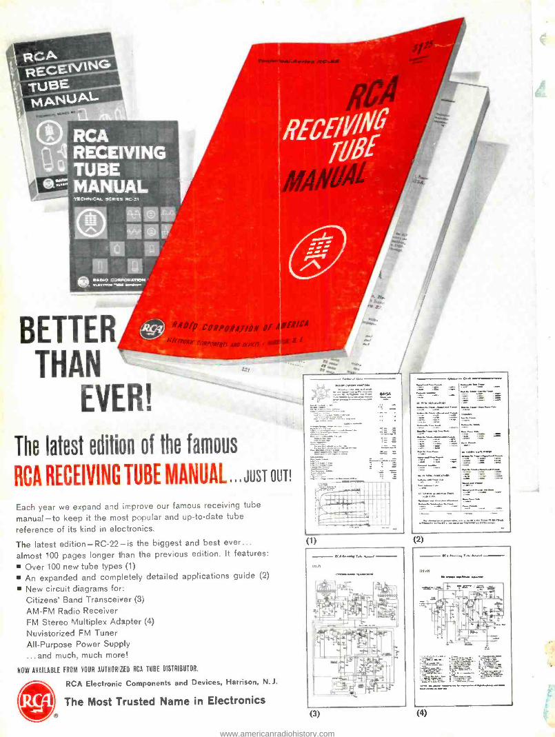
s. II. . ivC-is
TECHNICAL W'-MEE RC_I
.ADIO CJIMORAT0.1 avocrwc... -wan 01111/11.1.1
BETTER THAN
EVER!
..
i_,
The latest edition of the famous
RCA RECEIVING TUBE MANUAL ..JUST OUT!
Each year we expand and improve our famous receiving tube
manual -to keep it the most popular and up -to -date tube
reference of its kind in electronics.
The latest edition- RC -22 -is the biggest and best ever...
almost "00 pages longer than tie prey ous edition. It features:
Over 100 new tube types (1)
An expanded and completely detailed applications guide (2)
New circuit diagrams for:
Citizens' Banc Transceiver (3,
AM -FM Radio Receiver FM Stereo Multiplex Adipter (4)
Nuvis- orized FM Tuner All- Purpose Power Supply
...and much, much mo-e!
NOW AVAILABLE FROM YOUR AUTHOR ZED RCA TUSE DISTRIBUTOR.
0 RCA Electronic Components and Devices, Harrison, N.J.
The Most Trusted Name in Electronics VIke
a
6146
1E: SE
(1) (2)
(3) (4)
www.americanradiohistory.com