elektromehaniČki sustavi electromechanical systems tema 1 elektromagnetska pretvorba topic 1 energy...
TRANSCRIPT
ELEKTROMEHANIČKI SUSTAVI Electromechanical Systems
Tema 1Elektromagnetska pretvorba
Topic 1Energy conversion

Electromechanical systems
Block structure shematics of electromechanical system
Energy flow
Transmission (e.g.GearsSensor
Electric motor
Controller
Diagnostick, supervision
El. Power Supply Signal
flow
Power converters
Power converters

Structure of the electronics converter
Electromechanical sistemsElectromechanical sistems
Energy flow
El. System A Power electronics
Information system
Power converter structure

What is our task?
a) Introduction in basic components; how does it work ?
b) Analyze components of electromechanical systems (EMS), to learn the way of working and way of control with the purpose of the energy conversion (from electrical in mechanical and vice versa)
c) When one synthesize EMS, it should take a care of the energy efficiency
d) Set the request on the EMS components with the purpose of realisation above mentioned request
e) We will consider only such EMS where energy conversion produce the motion
f) The type of the motion will be mainly linear or rotational
Electromechanical SystemsElectromechanical Systems

Electromechanical SystemsElectromechanical Systems
• Literature:
• F. Kolonić: Textual materijals : Electromechanical System Control Course, 2012, Zagreb, Faculty of Electrical Engineering and computing, University of Zagreb.
• Werner Leonhard: Control of electrical Drives, 2007
• N. Mohan: Advanced Electric Drives-Analyses, Control and Modeling using Simulink, MNPERE, Mineapolis, 2001.

Electromechanical System (EMS) is system which consists of minimum one electrical and one mechanical subsystem (systems) coupled with electromagnetic fields .
With electro-magnetic field mutual interaction between those two (sub)systems has been performed.
U, I M, n
Electrical system
Coupled Field Mechanical
system
Electromagnetic field represent the coupled (bracing) field.
As a mutual action between magnetic field and subsystems, the energy conversion is realized from electrical to mechanical and vice-versa.
Electromechanical SystemsElectromechanical Systems

Energy balance in electromechanical system
Losses
Energy exchange of EMS with electrical system is:
WE = Wel + Wae + Wge
Energy from electrical source
Electrical energy transfered to magnetic field
Losses in elektrical system (heat)
Electrical energy in magnetic field which doesn’t belong to el.mag. field
Positive if EMS accept energy from electrical system
(1)
Electromechanical SystemsElectromechanical Systems

WM = Wmeh + Wam + Wgm
Energy from mechanical source
Energy from meh. system transfered to magnetic field
Losses in mechanical system (heat)
Energy accumulated in moving and elastic parts of mechanical system
Losses
Energy which EMS exchange with mehanical system
Positive if EMS accept energy from mechanical system
(2)
Electromechanical SystemsElectromechanical Systems
Energy balance in electromechanical system
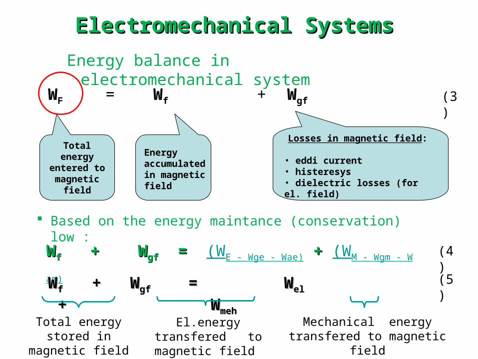
WF = Wf + Wgf
Energy accumulated in magnetic field
Losses in magnetic field:
• eddi current• histeresys• dielectric losses (for el. field)
Based on the energy maintance (conservation) low :
WWff + W+ Wgfgf == (WE - Wge - Wae) ++ (WM - Wgm - Wam)
WWff + W+ Wgf gf = = W Welel ++ W Wmeh meh
Total energy stored in magnetic field
El.energy transfered to magnetic field
Mechanical energy transfered to magnetic field
Total energy entered to magnetic
field
(3)
(4)
(5)
Electromechanical SystemsElectromechanical Systems
Energy balance in electromechanical system
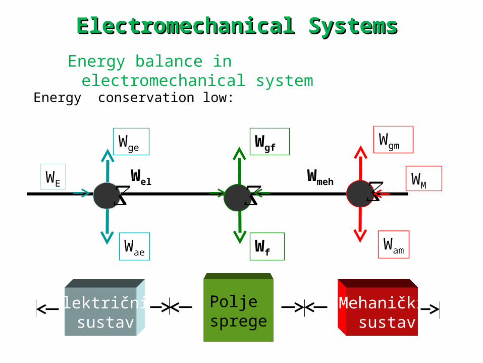
WE
Wge
Wae
WgfWgm
WfWam
WMWel Wmeh
Energy conservation low:
Polje sprege
Električni sustav
Mehanički sustav
Electromechanical SystemsElectromechanical Systems
Energy balance in electromechanical system
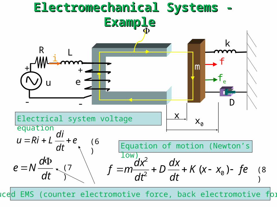
Electromechanical Systems - Example Electromechanical Systems - Example
xx0
+
-
e
iLR
u
+
-
k
f
fe
D
m
fexxKdt
dxD
dt
dxmf )( 02
2
Equation of motion (Newton’s low)
Electrical system voltage equation
dt
dNe
Induced EMS (counter electromotive force, back electromotive force )
edt
diLRiu (6)
(7) (8)

EMS components description:
R →parameter of coil (winding), resistance,
L → parameter of coil (winding), inductance, reactance)
K → parameter of spring, (coefficient of elasticity, stiffness)
D →parameter of spring, (damping coefficient )
m → mass of EMS
f → external force on mass (mass “m”)
fe → electromagnetic force
x0→ steady state position, equilibrium point of mechanical system, f =fe (forces f and fe are positive if x increse!)
x → position, mechanical variable
Electromechanical SystemsElectromechanical Systems
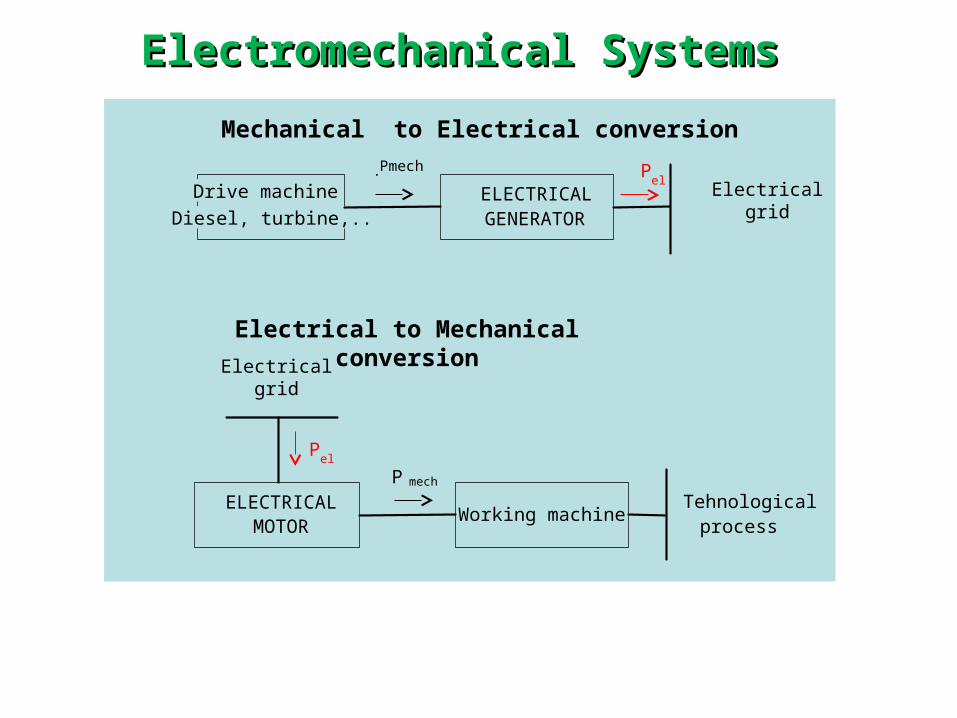
Drive machine
Diesel, turbine,..ELECTRICALGENERATOR
Electricalgrid
Pel
PPmech
Electrical to Mechanical conversion
ELECTRICALMOTOR
Working machine
Pel
PTehnological process
Mechanical to Electrical conversion
Electricalgrid
Electromechanical SystemsElectromechanical Systems
mech

The basics of electromechanical conversion
1. Voltage inducing in moving coil vertical to magnetic field
2. Positive and negative charge split up to the ends of coil; the voltage is generated! This is called as Faraday - Lentz low.
E x l v B
3. Direction of induced voltage is defined with Right hand rule. If the field is going to the flat of the hand and thumb shows direction of the coil motion, positive voltage is in direction of the fingers top.
(14)
Electromechanical SystemsElectromechanical Systems

4. The force applied to the coil with current which move in magnetic fields is defined by (15).
5. The direction of the electromagnetic force is defined by the Left hand rool. If the field is going to the flat of the hand and direction of the fingers are in positive voltage, then the direction of force is in direction of the thumb.
I x eF F l B
Obtained force on the coil doesn’t mean that mechanical work is produced!!
(15)
Electromechanical SystemsElectromechanical Systems

6. Direction of the energy conversion
If the motion velocity (v) of the coil is caused by force F in magnetic field B, then induced voltage E will be according to the green arrow.
If the ends of the coil are connected to the resistor R, the current will flow and as consequence electromagnetic force Fe will be
generated. This force is opposite to the F force, F= - Fe
vdtFdxFdW eemeh
EIdteidtdWel
El.energy in interval dt
Mechanical work is negative, (direction of force and trip (distance) are not the same!
(16)
(17)
R
BE
FFe
I
v
Electromechanical SystemsElectromechanical Systems
vdtFdxFdW eemeh

6. Direction of energy conversion (continuing)
Negative sign of the work (17) means that mechanical system doesn’t receive energy, i.e. It must generate energy (i.e.work) to enable the moving the coil with the same speed during the time dt.
Electrical energy is produced and mechanical energy is consumed. This example illustrates principal of the generator work!
Electromechanical SystemsElectromechanical Systems
vdtFdxFdW eemeh
EIdteidtdWel
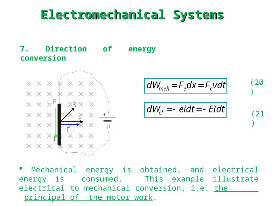
7. Direction of energy conversion
Mechanical energy is obtained, and electrical energy is consumed. This example illustrate electrical to mechanical conversion, i.e. the
principal of the motor work.
(20)
(21)BE
Fe
I
v
U
+
Electromechanical SystemsElectromechanical Systems
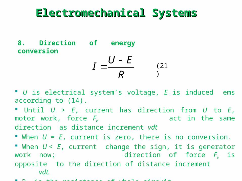
8. Direction of energy conversion
U is electrical system’s voltage, E is induced ems according to (14). Until U > E, current has direction from U to E, motor work, force Fe
act in the same direction as distance increment vdt When U = E, current is zero, there is no conversion. When U < E, current change the sign, it is generator work now;
direction of force Fe is opposite to the direction of distance increment vdt. R is the resistance of whole circuit.
R
EUI
(21)
Electromechanical SystemsElectromechanical Systems
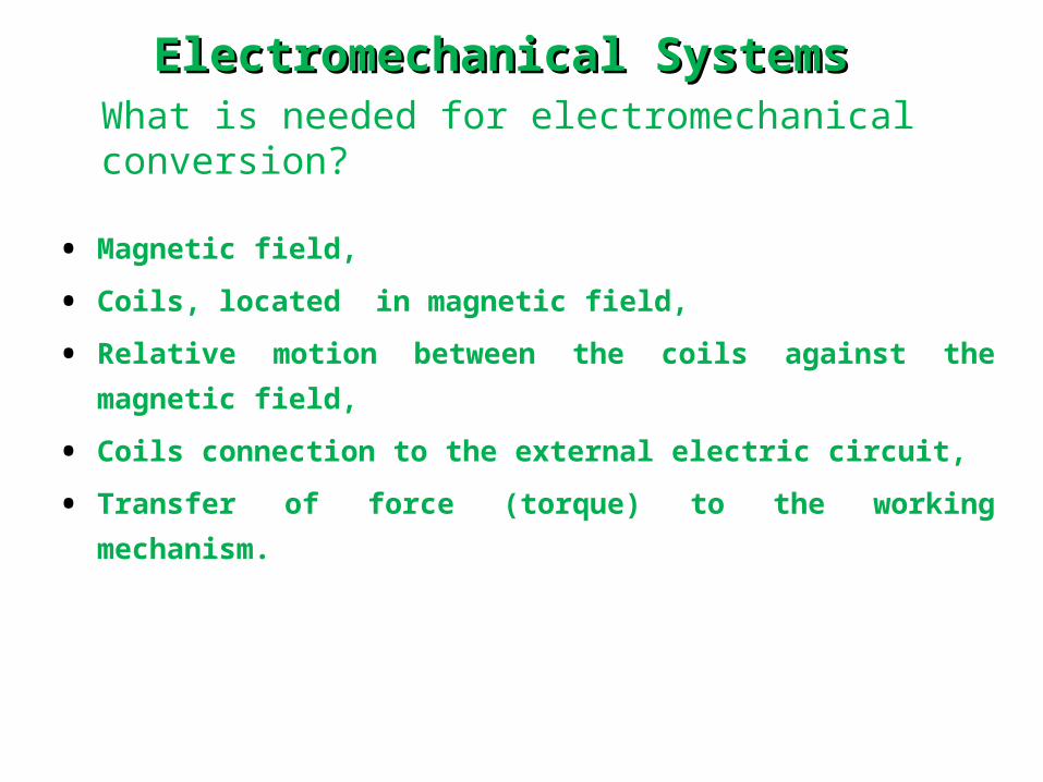
What is needed for electromechanical conversion?
• Magnetic field,
• Coils, located in magnetic field,
• Relative motion between the coils against the magnetic field,
• Coils connection to the external electric circuit,
• Transfer of force (torque) to the working mechanism.
Electromechanical SystemsElectromechanical Systems

2. Limitation in expression E = B l v:
• The amount of induction B is limited by ferromagnetic
materials Bz ≈ (1,7 - 2) T
• The length of the coil(l) is limited by mechanical reasons (problems
of embedding)
• The maximal speed is limited by construction strength, friction
losses and heating caused by friction
1. Magnetic field :
•It can be realized with electromagnets or with permanent magnets
•Permanent magnets are with limited dimensions, they are used for
electrical machines with limited dimensions and power ratings .
Electromechanical SystemsElectromechanical Systems

Magnetic field with permanent magnets
Magnetic circuit realized with permanent magnet, soft magnetic material
(iron)
B – induction in air gap
Φ – magnetic field in core (constant)
Electromechanical SystemsElectromechanical Systems
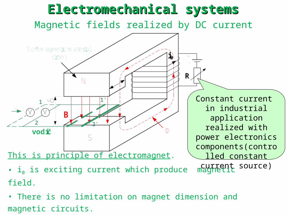
Magnetic fields realized by DC current
This is principle of electromagnet.
• i0 is exciting current which produce magnetic field.
• There is no limitation on magnet dimension and magnetic circuits.
• Changing R in exciting coil, the amount of current doesn’t change,
as well as magnetic field of the core.
Constant current in industrial application realized with power
electronics components(controlled
constant current source)
Electromechanical systemsElectromechanical systems
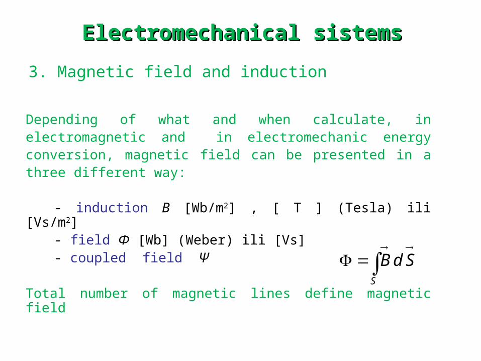
3. Magnetic field and induction
Depending of what and when calculate, in electromagnetic and in electromechanic energy conversion, magnetic field can be presented in a three different way:
- induction B [Wb/m2] , [ T ] (Tesla) ili [Vs/m2] - field Φ [Wb] (Weber) ili [Vs] - coupled field Ψ
Total number of magnetic lines define magnetic fieldS
Bd S
Electromechanical sistemsElectromechanical sistems

4. Vodiči smješteni u magnetskom polju
Axial conductors in slots of stator conductors design (windings), b); slotting design c)
Important: System of rings (or slices of collectors) and brushes, enable connection of rotary elements with stationary world, a)
b)
c)
a)
Electromechanical systemElectromechanical system

5. Relative motion of coil against the lines of magnetic fields
Translational (linear) a) and rotation motion b) of coil in air gap. Principle of translational and rotational motion of electrical machine)
Important: air gap must be very narrow! With equal magnetic field, narrower air gap results with higher induction in the air gap (minor loss of magnetic lines)
a) b)
Elektromehanički sustaviElektromehanički sustavi

Example: Force on conductor
Simplified “magnetic lift” is presented on
the picture, see figure. Distance
between vertical rigid rods is 0,5 m, and
mass of load for hoisting is 2 kg. Mass
of coil is 1kg. Influence of friction force
can be neglected.
a) Calculate the current thru coil in order to lift-up load a) and hang
the load in desired position, b).
b) If the current is 50 A, find the direction of force and motion.
Calculate the acceleration of the lift
I
B = 1,5 T
= 0,5 m
vertical conductive
rod
coil
F
Fg
Electromechanical systemsElectromechanical systems

SOLUTION:
a) For zero motion of coil and load, electromagnetic force on coil
and load must be equal to gravitation force,
F = F g B I l= (m v + m t) 9,81
If the coil and load must be moved up (hoist), electromagnetic force
on coil must be higher than the gravitation force:
F > F g I > 39,24 A
b) Electromagnetic force with current of 50A iz: F = B I l = 1,5∙50∙0,5 =
37,5 N
gravitation force: F g = mg = (2+1)∙9,81= 29,43 N
Acceleration force: F u = F – F g = 37,5 – 29,43 = 8,07 N
Electromechanical systemsElectromechanical systems

Electromechanical systemsElectromechanical systemsREMINDER: Basics of electromechanical systems
1. The force on the moving charge in magnetic field of induction B:
• Direction of force F (Fem) is defined by right screw rule. Force act in direction of the screw advancing
BvF xQ
(13)
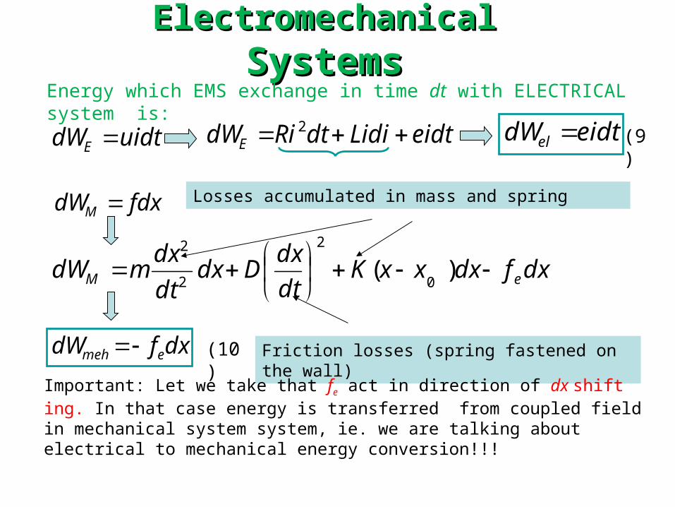
ElectromechanicalElectromechanical Systems SystemsEnergy which EMS exchange in time dt with ELECTRICAL system is:
uidtdWE eidtLididtRidWE 2 eidtdWel
fdxdWM
dxfdW emeh
Losses accumulated in mass and spring
dxfdxxxKdt
dxDdx
dt
dxmdW eM
)(
0
2
2
2
Friction losses (spring fastened on the wall)
Important: Let we take that fe act in direction of dx shift ing. In that case energy is transferred from coupled field in mechanical system system, ie. we are talking about electrical to mechanical energy conversion!!!
(9)
(10)

Electromechanical Electromechanical systemssystems U promatranom EMS-u polje sprege je MAGNETSKO polje, pa se za
akumuliranu energiju polja sprege koristi pojam MAGNETSKA energija i označava se s Wm.
Na osnovi prethodnih razmatranja, za prirast akumulirane magnetske energije dWm,dobije se
dxfeidtdW em
Jednadžba se može poopćiti na EMS s proizvoljnim brojem električnih i mehaničkih ulaza i proizvoljnim brojem sprega.
mehelm dWdWdW (11)
(12)
END