elementary graphi 00wighrich
TRANSCRIPT
7/29/2019 Elementary Graphi 00wighrich
http://slidepdf.com/reader/full/elementary-graphi-00wighrich 1/256
7/29/2019 Elementary Graphi 00wighrich
http://slidepdf.com/reader/full/elementary-graphi-00wighrich 2/256
7/29/2019 Elementary Graphi 00wighrich
http://slidepdf.com/reader/full/elementary-graphi-00wighrich 3/256
7/29/2019 Elementary Graphi 00wighrich
http://slidepdf.com/reader/full/elementary-graphi-00wighrich 4/256
7/29/2019 Elementary Graphi 00wighrich
http://slidepdf.com/reader/full/elementary-graphi-00wighrich 5/256
7/29/2019 Elementary Graphi 00wighrich
http://slidepdf.com/reader/full/elementary-graphi-00wighrich 6/256
7/29/2019 Elementary Graphi 00wighrich
http://slidepdf.com/reader/full/elementary-graphi-00wighrich 7/256
ELEMENTARY GRAPHIC STATICS

7/29/2019 Elementary Graphi 00wighrich
http://slidepdf.com/reader/full/elementary-graphi-00wighrich 8/256
Whittaker's Practical Handbooks
ADAMS,H. Practical
Trigonometry, 2/6
net.
ARNOLD and IBBOTSON. Steel Works Analysis, 10/6 net.
ATKINS, E. A. Practical Sheet and Plate Metal Work, 6/- net.
BAMFORD. H. Moving Loads on Railway Underbridges, 4/6 net.
BJORLING, P. R. Pipes and Tubes, 3/6 net.
DAVIS, W. E. Quantities and Quantity Taking, 3/6 net.
FARROW, F. R. Stresses and Strains, 5/- net.
., ,,
Specifications
for
Building Works, 3/6
net.
FLETCHER, B. F. and H. P. Carpentry and Joinery, 5/- net.
,, ,, Architectural Hygiene, o/- net.
FODEN, J Mechanical Tables, 1/6 net.
GREENWELL and ELSDEN. Roads : their Construction and
Maintenance, 5/- net.
HORNER, J. G. Metal Turning, 3/6 net.
,, ,, Principles of Fitting, 5/- net.
,, ,, Practical Ironfounding, 5/- net.
,, ,, Principles of Pattern Making, 3/6 net.
MIDDLETON, G. A. T. Surveying and Surveying Instruments,
5/- net.
ROBERTS, C. W. Drawing and Designing for Marine Engineers,
5/- net.
ROBERTS, C. W. Practical Advice for Marine Engineers, 3/- net.
STEVENS and HOBART. Steam Turbine Engineering, 21/- net.
THURSTON, A. P. Elementary Aeronautics, 3/6 net.
TWELVETREES, W. N. Concrete Steel, 6/- net.
,, ,, Concrete Steel Buildings, 10/- net.
,, ,, Practical Design of Reinforced Con-
crete Beams and Columns, 6/- net.
TWELVETREES, W. N.-Structural Iron and Steel, 6/- net.
WALMISLEY,A. T. Land
Surveyingand
Levelling, 6/-
net.
,, ,, Field Work and Instruments, 5/- net.
WHITTAKER'S Electrical Engineers' Pocket Book, 5/- net.
,, Mechanical Engineers' Pocket Book, 6/- net.
WILLIAMS, H. Mechanical Refrigeration, 9/- net.
WHITTAKER & CO., 2 White Hart St., LONDON, E.G.
7/29/2019 Elementary Graphi 00wighrich
http://slidepdf.com/reader/full/elementary-graphi-00wighrich 9/256
ELEMENTARY
GRAPHIC STATICS
BY
JOHN T. WIGHT, A.M.I.MECH.E.
Lecttirer in Machine Design and Prime Mover-s,
Heriot-Watt College, Edinburgh
Honours Medallist and Prizeman in Mechanical Engineering
( City and Guilds of London Instititte}
WITH 135 ILLUSTRATIONS
WHITTAKER & CO.
2 WHITE HART ST., PATERNOSTER SQ.
LONDON, E.G.
AND 64 AND 66 FIFTH AVENUE, NEW YORK
1913
7/29/2019 Elementary Graphi 00wighrich
http://slidepdf.com/reader/full/elementary-graphi-00wighrich 10/256

7/29/2019 Elementary Graphi 00wighrich
http://slidepdf.com/reader/full/elementary-graphi-00wighrich 11/256
CONTENTS
CHAPTER I
PAGE
INTRODUCTION
.....1
Definition and Specification of a Force Graphic Repre-
sentation of a Force Coplanar Forces Concurrent
and Non-concurrent Forces Composition and Resolution
of Forces Resultant Equilibrant Units
CHAPTER II
COMPOSITION AND RESOLUTION OP FORCES . . 11
Forces Acting in the same Straight Line Resultant of
Two Concurrent Forces Parallelogram of Forces
Triangle of Forces Polygon of Forces Examples
Worked Out Bow's Notation
CHAPTER III
SIMPLE PRACTICAL PROBLEMS . .
.33Loaded Platform Triangular Frame Shear Legs
Tripod Simple Crane Simple Crane with Lifting
Chain Rotating Crane Warehouse Crane
CHAPTER IV
COMPOSITION OP NON-CONCURRENT FORCES. .
46Funicular Polygon Resultant of Non-concurrent Forces
Resultant of Like Parallel Forces Resultant of
Unlike Parallel Forces Moments Graphic Representa-
tion of Moments Moment of a System of Non-parallel
Forces Moment of a System of Parallel Forces
Couples
vii
282178

7/29/2019 Elementary Graphi 00wighrich
http://slidepdf.com/reader/full/elementary-graphi-00wighrich 12/256
viii CONTENTS
CHAPTER VPAGE
BENDING MOMENT AND SHEARING FORCE DIAGRAMS 63
Definitions Construction of Parabola Cantilever
(Concentrated Load) Cantilever (Distributed Load)
Supported Beam (Concentrated Load) Supported Beam
(Distributed Load) Unsymmetrically Loaded BeamsScales of B.M. and S.F. Overhung Beam (Concentrated
Loads) Supported Beam(Compound Loading)
Over-
hung Beam (Compound Loading)
CHAPTER YI
BEAMS WITH ROLLING LOADS . . 89
Single Concentrated Rolling Load Uniformly Dis-
tributed Rolling Load Combined Dead and Rolling
Loads
CHAPTER VII
ROOFS SYMMETRICAL DEAD LOADS . . 99
Frames Definitions Distribution of Leading Types
of Roofs Plain Rafters without Tie-rod Plain Rafters
with Tie-rod Simple King-rod Truss Simple Swiss
Truss Compound Swiss Truss Compound Swiss Truss
(Right-angled Struts) Simple King-rod Truss (Single
Struts) King-rod Truss (Single Struts and Inclined
Ties) Belgian Truss English Truss Simple Queen-
post Truss Compound Queen-post Truss French
Truss Mansard Truss
CHAPTER VIII
ROOFS UNSYMMETRICAL LOADING . . .135
Northern Lights Roof Overhung Roof Overhung Roof
with Pillar Island Station Roof
7/29/2019 Elementary Graphi 00wighrich
http://slidepdf.com/reader/full/elementary-graphi-00wighrich 13/256
CONTENTS ix
CHAPTER IXPAGE
ROOFB WIND PRESSURE
....144
Calculation of Wind Pressure Experimental Results
Maximum Wind Pressure Determination of Stress due
to Wind Comparison of Methods Roof with Free End
Saw-tooth or Northern Lights Roof Island Station
Roof
CHAPTER XBRACED BEAMS AND GIRDERS . . .166
Braced Beam (Single Stanchion) Braced Beam (Double
Stanchion) Trapezoidal Truss Fink Truss Bollman
Truss Warren Girder Linville Girder Pratt Truss
Lattice Girders Cantilever Pier
CHAPTER XI
CENTRE OF GRAVITY NEUTRAL Axis RESISTANCE
FIGURES MOMENTS OF INERTIA . .189
Gravity Experimental Method of finding the C.G.
Centre of Gravity of a Triangle Centre of Gravity of a
Parallelogram Centre of Gravity of Irregular Surfaces
Funicular Polygon Method Cast-iron Beam Section
Neutral Axis Resistance Figures Modulus of Section
Moment of Inertia Moment of Inertia of a Particle
Moment of Inertia of a System of Forces Mohr's Method
Moment of Inertia of Ferro-concrete Section
CHAPTER XII
RETAINING WALLS . . . . .218
DefinitionsSimple Case of Water Pressure ExampleEarth Pressure Rankine's Theory Coulomb's
Theory Example Rebhann's Method

7/29/2019 Elementary Graphi 00wighrich
http://slidepdf.com/reader/full/elementary-graphi-00wighrich 14/256

7/29/2019 Elementary Graphi 00wighrich
http://slidepdf.com/reader/full/elementary-graphi-00wighrich 15/256
PREFACE
IN lecturing on the subject of Graphic Statics to
first-year students, the Author has always felt the
want of a suitable text-book which could be re-
commended to students in search of a working
knowledge of the application of graphical methods
to the solution of the simpler problems met with in
Engineering and Building Construction practice.
It is not given to every one to be mathematically
brilliant, but this is no reason why the young
engineer should be denied the privilege of studying
much in engineering which interests and appeals to
him. In the solution of engineering problems, the
science of Graphics presents a ready means of
circumventing the many intricate and cumbrous
mathematical equations which can, all too easily,
clothe comparatively simple problems with an air
of
mystery
anddifficulty.
There are those who scoff at graphical methods,
forgetting that there are hundreds of first-class
practical engineers who are daily solving some of
the most useful problems of everyday life by such
methods. The work of such men is alone a sufficient
xi

7/29/2019 Elementary Graphi 00wighrich
http://slidepdf.com/reader/full/elementary-graphi-00wighrich 16/256
xii PREFACE
justification of the existence of graphical methods in
their application to engineering problems.
It only lies with the student to realize that every
problem set out in the following pages must be
carefully worked out and thoroughly understood.
Mere reading of the subject matter is worse than
useless.
The Sftudent who conscientiously works through
all the problems and examples which follow, will
have acquired much that will stand him in good
stead in the performance of useful engineering
work.
JOHN T. WIGHT.
HERIOT-WATT COLLEGE,
EDINBURGH, October 1913.
7/29/2019 Elementary Graphi 00wighrich
http://slidepdf.com/reader/full/elementary-graphi-00wighrich 17/256
ELEMENTARY GRAPHIC
STATICS
CHAPTER I
INTRODUCTION
IT is unnecessary to tell those who are interested
in any branch of science, that scientific discovery
depends, to no small extent, on measurement
accurate measurement. Scientific discovery is indeed
restricted to a few, yet it does not necessarily follow
that the need for accurate measurement is likewise
restricted;the importance of it is exemplified in
practically everything around us, and in no other
profession, perhaps, is its importance and utility so
significant as in that of engineering. In every
branch of engineering its importance is undisputed,
and its application, in conjunction with geometric
methods, to the solution of engineering problems,
provides a study of extreme utility and interest.
Accuracy, both in drawing and in measurement,
cannot be too strongly emphasized, for this is the
keynote of success in the solution of all problems in
Graphic Statics.
The one objection levelled against this science
7/29/2019 Elementary Graphi 00wighrich
http://slidepdf.com/reader/full/elementary-graphi-00wighrich 18/256
2 ELEMENTARY GRAPHIC STATICS
is the liability to error introduced by inaccurate
drawing and measurement. In its application to
engineering problems such an objection is hardly
valid, for, by exercising moderate care in the
different operations involved, we can attain to an
accuracy of 1 per cent. accuracy sufficient for all
practical purposes.Its advantages are manifold, enabling us to solve,
readily and quickly, many problems which would
otherwise require much intricate and cumbrous
mathematical investigation. In many engineering
problems we deal with forces and velocities, quantities,
in themselves, purely abstract, and surelyit is
a great
advantage to the practical mind to be able to repre-
sent such things on paper, if even in a comparative
way, greater still to be able, by the deft use of a few
simple drawing instruments, to discover the effects
produced by such forces and velocities at any point
in a given system.Definition and Specification of a Force. Before
proceeding to treat the more graphical part of the
subject, it might be well to deal briefly with'''force
and its specification"
Force. Force is any cause which produces or tends
to produce motion or change of motion in a body.This definition is quite general in its application,
conveying to us only a very vague notion of a
force through the medium of the effect produced
thereby, and before we can put anything on paper
regarding it, we must have fuller information on a
few points concerning the force.

7/29/2019 Elementary Graphi 00wighrich
http://slidepdf.com/reader/full/elementary-graphi-00wighrich 19/256
INTRODUCTION 3
The question naturally arises :
"
What are the
points necessary to completely specify a force ?"
Such a specification must embody four things, viz. :
(a) Point of Application.
(b) Direction.
(c) Magnitude.
(d) Sense.
Graphic Representation of a Force. Let us now
consider how each of these items can be represented
graphically.
Point of Application. In all our calculations in
statics we have considered forces as acting at points ;
if we must be accurate, how then can we representthe point of application, since our idea of a point
precludes any idea of area, and any mark we maymake on paper must, of necessity, cover some area,
no matter how small ? For our purpose we must
give up this mathematical idea of a point in this
connection, and consider the point of application asa small area to which we have given the name"
point."
Take for illustration the case of an engine push-
ing a train. The points of application, in this in-
stance, are the buffers, in themselves presenting an
appreciable area, yetso small in
comparisonto
thewhole area of the end of the train as to justify our
calling them "points of application." Generally
speaking, the point of application is the exact region
in which the force acts, so that the demands of
accuracy will be satisfied if we represent the point
of
application byapencil
dot on thepaper.
7/29/2019 Elementary Graphi 00wighrich
http://slidepdf.com/reader/full/elementary-graphi-00wighrich 20/256
ELEMENTARY GRAPHIC STATICS
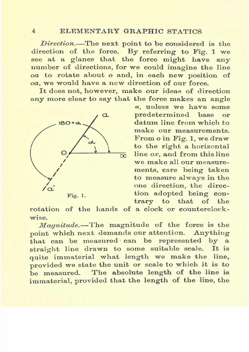
Direction. The nextpoint
to be considered is the
direction of the force. By referring to Fig. 1 we
see at a glance that the force might have anynumber of directions, for we could imagine the line
od to rotate about o and, in each new position of
oa, we would have a new direction of our force.
It does not,however,
make our ideas of direction
any more clear to say that the force makes an angle
,unless we have some
predetermined base or
datum line from which to
make our measurements.
From o in
Fig.1, we draw
to the right a horizontal
line ox, and from this line
we make all our measure-
ments, care being taken
to measure always in the
one direction, the direc-
tion adopted being con-
trary to that of the
rotation of the hands of a clock or counterclock-
wise.
Magnitude. The magnitude of the force is the
point
which next demands our attention.
Anythingthat can be measured can be represented by a
straight line drawn to some suitable scale. It is
quite immaterial what length we make the line,
provided we state the unit or scale to which it is to
be measured. The absolute length of the line is
immaterial,provided
that the
length
of the line, the

7/29/2019 Elementary Graphi 00wighrich
http://slidepdf.com/reader/full/elementary-graphi-00wighrich 21/256
INTRODUCTION 5
quantitythat it
represents
and the scale of measure-
ment are all in harmony.
For example, say we wish to represent a force of
50 Ibs.;
it does not matter whether the line be 3 in.
long or 4 in., if the scale be chosen accordingly, but, if
our scale be fixed at 1 in.= 20 Ibs., then the length
of the line must be 2*5 inches, and not a fraction
more or less.
The choice of a scale depends on the magnitude of
the forces with which we are dealing, and also on
the space at our disposal on the drawing-paper. The
important point to keep in mind is, that the maximum
possible extent of our error in
drawing
is a constant,
while the size of our drawings varies, so that the
larger the scale, the percentage error is the less, or,
in other words, the larger the scale the greater the
accuracy.
Sense. The only point remaining to be settled
is the sense of the force. We may have settled and
represented the three preceding points, but we maystill be uncertain as to whether the force acts awayfrom the point or towards it whether it is a pull or
a push but this can be indicated by putting an
arrowhead on the line of action of the force.
In dealing, however, with the sense of a force, it is
conventional to assume that positive forces act away
from the point, while negative forces act towards it,
so that in all cases, unless the force be preceded by a
minus sign, we take it that the force acts away from
the point. Thus, for example, if we had a force of
60 Ibs., pulling on a point at an angle of 45, it would

7/29/2019 Elementary Graphi 00wighrich
http://slidepdf.com/reader/full/elementary-graphi-00wighrich 22/256
6 ELEMENTARY GRAPHIC STATICS
be written, 6045 Ibs., but if the same force were
pushing on the point it would be written, 6045
Ibs.
It may be worth noting, in passing, that Pa=
Pi80 + a- This will be more readily understood by
reference to Fig. 1. As far as the point o is concerned,
it is immaterial whether the force P acts along oa
as a pull or along oa' as a push, provided oa and
oa' are in the same straight line. Now oa is a
positive force acting at an angle ,and hence we
write it oaa ,while the force along oa' is a negative
force, and hence we write it oa'iso + a- - But we
have seen that the effect on o produced by either
force is the same, so that oaa= oa'iso + a- In
more general terms this may be written
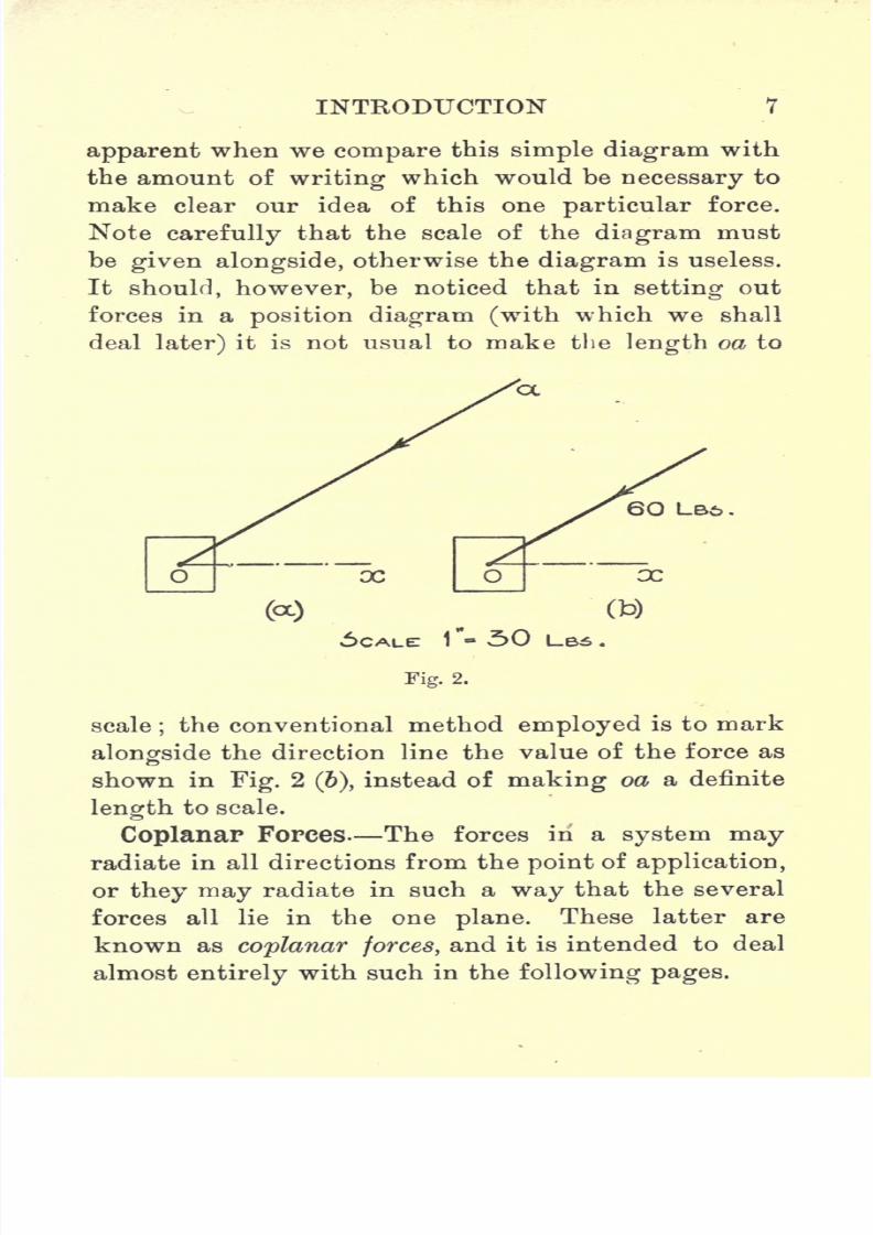
To show the application of the ideas embodied in
the foregoing definitions we will now consider the
graphical representation of the force, 6035 Ibs., acting
on a given point o.
We are given the point of application o as shown
in Fig. 2 (a), and, as for the direction, we see that it
makes an angle of 35, so that we mark off this angle,
measuring counterclockwise from our datum line,
ox. Before we can fix the length of oa we must
select a scale, and assuming this to be 1 in. = 30 Ibs.,
we proceed to mark off a length oa equal to 2 in.
We further notice that the force is negative, and
consequently we must put on an arrowhead acting
towards the point o.
This diagram now represents one definite force and
only one, and one advantage of graphics becomes
7/29/2019 Elementary Graphi 00wighrich
http://slidepdf.com/reader/full/elementary-graphi-00wighrich 23/256
INTRODUCTION 7
apparent when we compare this simple diagram with
the amount of writing which would be necessary to
make clear our idea of this one particular force.
Note carefully that the scale of the diagram must
be given alongside, otherwise the diagram is useless.
It should, however, be noticed that in setting out
forces in a position diagram (with which we shall
deal later) it is not usual to make the length oa to
6O LB6 .
5CALET 1"- 30 L-BS .
Fig. 2.
scale;the conventional method employed is to mark
alongside the direction line the value of the force as
shown in Fig. 2(6),
instead of making oa a definite
length to scale.
CoplanaP Forces The forces in a system mayradiate in all directions from the point of application,
or they may radiate in such a way that the several
forces all lie in the one plane. These latter are
known as coplanar forces, and it is intended to deal
almost entirely with such in the following pages.
7/29/2019 Elementary Graphi 00wighrich
http://slidepdf.com/reader/full/elementary-graphi-00wighrich 24/256
8 ELEMENTARY GRAPHIC STATICS
Concurrent and Non-concurrent Forces. If, in
any system, the several forces have a common point
of application, such forces are said to be concurrent ;
but if they do not have a common point of application,
but are applied to the body at various points, so
situated that the several lines of action, if produced,
would not intersect in a common point, such forces
are said to be non-concurrent.
Composition and Resolution of Forces. When
we have a number of forces acting on a body we can,
by suitable constructions, combine these forces, and
so find one single force which, acting alone, would
produce the same effect as the several forces acting
together. Such a process is known as the composi-
tion of forces, and the single force, so found, as the
resultant.
Resultant. The resultant of any system of forces
is that single force ivhich, acting alone, would produce
the same effect as the several primary forces acting
together.
When we have a single force acting on a body
we can, by suitable constructions, find the values
of any number of forces whose combined effects,
when acting in unison, produce the same effect
as that of the single force acting alone. Such a
process is known as the resolution of forces, and the
several forces, so found, as components. It should,
however, be noted, that the resolution of a force into
any number of components is capable of an infinite
number of solutions, but, in general, definiteness is
given to the solution by practical considerations

7/29/2019 Elementary Graphi 00wighrich
http://slidepdf.com/reader/full/elementary-graphi-00wighrich 25/256
INTRODUCTION 9
either the
magnitudes
or directions of certain of the
forces will be given.
Equilibrant. The equilibrant of a system of
forces is that single force which, when applied to
that system, equilibrates or neutralizes its effect.
The equilibrant must be carefully distinguished
from the resultant. Referring to Fig. 3, and com-
paring these two along the lines of the specification
we have drawn up, we find
(a) The point of application is the same.
(b) The magni-
tudes are equal, ^ i8O-
oa = oaf.
(c) The sense is
the same, both
being positive
and acting
away from the
point. Fig< 3<
(d} The directions
are diametrically opposed, the angle of the
resultant being ,while that of the equilibrant
is 180+ a.
The only point of difference then is in the directions,
the two being diametrically opposed to one another,
so that the effect of the equilibrant is to neutralize
that of the resultant, and so bring the whole system
into equilibrium. In general, when we have a given
force-effect, produced by a system of forces, the
resultant represents that force-effect, while the
equilibrant represents that single force which must
7/29/2019 Elementary Graphi 00wighrich
http://slidepdf.com/reader/full/elementary-graphi-00wighrich 26/256
10 ELEMENTARY GRAPHIC STATICS
be applied to the system to neutralize that force
effect.
Units- In absolute measurements the unit of force
which is used is the poundal. In engineering
problems, however, the unit of force is the pound.
The poundal may be defined as that force which,
acting on a mass of 1 pound, would
produce
in it
an acceleration of 1 foot per second per second.
We know that, if we drop a mass of 1 pound at the
earth's surface, the acceleration produced is approxi-
mately equal to 32 feet per second per second, and
hence it follows that, if the poundal produces unit
acceleration, the force acting on the mass must be 32
poundals.
It is this attractive force on a mass pound that we
use as our unit of force in engineering problems.
This value, however, varies slightly at different
parts of the earth's surface, but the variation is so
small as to be negligible in all practical problems.
The ton, consisting of 2240 Ibs., is frequently used
when dealing with problems involving large forces.
7/29/2019 Elementary Graphi 00wighrich
http://slidepdf.com/reader/full/elementary-graphi-00wighrich 27/256
CHAPTER II
COMPOSITION AND RESOLUTION OF FORCES
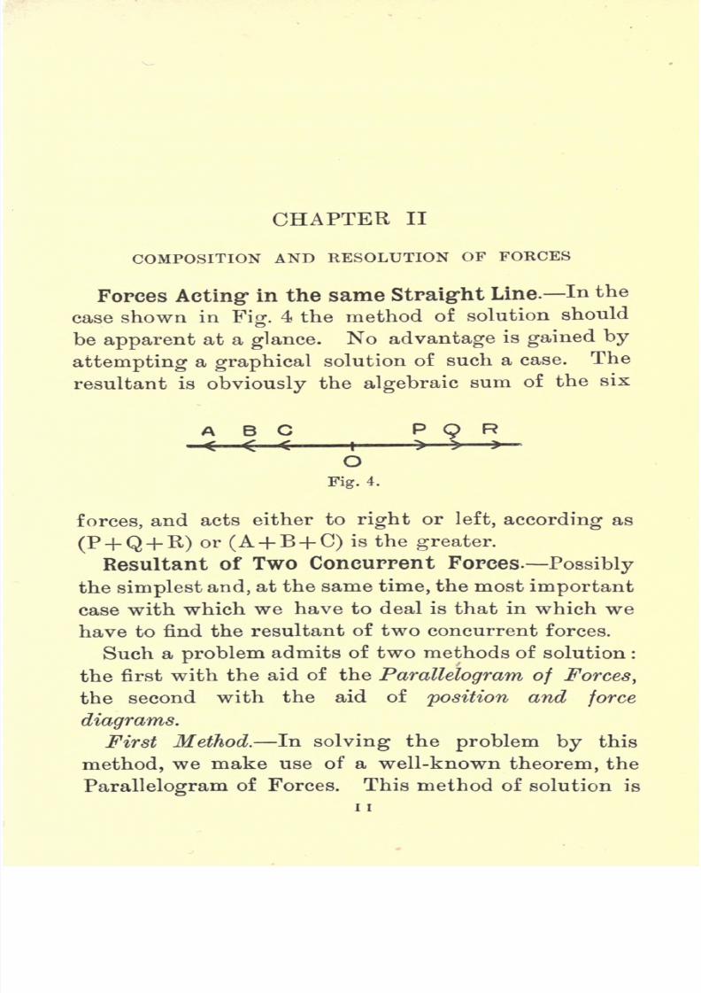
Forces Acting" in the same Straight Line. In the
case shown in Fig. 4 the method of solution should
be apparent at a glance. No advantage is gained by
attempting a graphical solution of such a case. The
resultant is obviously the algebraic sum of the six
ABC P R
OFig. 4.
forces, and acts either to right or left, according as
(P-f Q-f-R) or (A+ B+ C) is the greater.
Resultant of Two Concurrent Forces. Possibly
the simplest and, at the same time, the most important
case with which we have to deal is that in which we
have to find the resultant of two concurrent forces.
Such a problem admits of two methods of solution :
the first with the aid of the Parallelogram of Forces,
the second with the aid of position and force
diagrams.
First Method. In solving the problem by this
method, we make use of a well-known theorem, the
Parallelogram of Forces. This method of solution is

7/29/2019 Elementary Graphi 00wighrich
http://slidepdf.com/reader/full/elementary-graphi-00wighrich 28/256
12 ELEMENTARY GRAPHIC STATICS
not in
generaluse in the solution of
practical problems,yet there are many problems in which it can be very
readily applied, and it may be worth while considering
it a little in detail.
Parallelogram of Forces.// two forces acting on
a point be represented in magnitude and direction by
the
adjacent
sides
of
aparallelogram,
then the
diagonalthrough their intersection represents the resultant in
magnitude and direction.
In Fig. 5 we have two forces, P and Q, acting at a
Fig. 5.
point 0. Mark off along these two lines distances OAand OB equal to P and Q respectively, to some scale.
Complete the parallelogram OBCA and join OC.
Then 00 represents to scale the magnitude and
direction of the resultant.
This important proposition was first enunciated by
Sir Isaac Newton about the year 1687, and since that
time various proofs have been given by different mathe-
maticians. The following proof, due to Duchayla,
is probably the best known.

7/29/2019 Elementary Graphi 00wighrich
http://slidepdf.com/reader/full/elementary-graphi-00wighrich 29/256
RESOLUTION OF FORCES 13
Let a force P act on abody
at Aalong
the direction
AB, and two forces Q and W also act on A along the
direction ACD. Assume force W to act at the point
C and be represented by CD to scale. Complete the
parallelograms ACEB and ECDF. (Fig. 5A.)
The resultant of P and Q is assumed to be some
force
(say T) acting along
the line AE. These two
forces can be replaced by T and the point of applica-
tion of the force assumed at any point in its line of
A Q C W D
action. Let its point of application be E. This force
T, acting at E, may now be replaced by forces equal
to P and Q, acting in the directions EG and EF, and
further let their points of application be removed to
C and F. Acting now at C, we have two forces
P acting along CE and W acting along CD. Again
we can assume the resultant of P and W to be some
force (say S) acting along the line CF, and by taking
its point of application as F, we thereby apply all the
forces at one point without altering their combined
effect. Hence F is a point on the line of action of
7/29/2019 Elementary Graphi 00wighrich
http://slidepdf.com/reader/full/elementary-graphi-00wighrich 30/256
14 ELEMENTARY GRAPHIC STATICS
the resultant. Therefore AF is the direction of the
resultant.
For P we may write (rax/) and, for (W+ Q),
(n x/) and the same theorem holds. Hence in the
general case the diagonal represents the direction or
line of action of the resultant.
We must now consider the magnitude of the
resultant. Referring back to Fig. 5, we apply to the
system a force E, represented by OD, equal and
opposite to the combined effects of P and Q.
We know that the resultant of P and Q acts along
00, hence OD and OC will be in the same straight
line, and if OC represents the magnitude of the
resultant, then OC must equal OD. Complete the
parallelogram ODFA, and join OF. Now the result-
ant of E and P will act along OF, and since the point
O is in equilibrium under the action of three forces
P, Q and E, it follows that OB and OF must be in the
same straight line. The figure OFAC is therefore a
parallelogram, and consequently FA equals OC. But
FA equals DO, hence OC equals OD.
The length OC therefore represents the magnitude
of the resultant of P and Q, the inclination of the
line representing its direction.
This theorem can be demonstrated quite simply bythe aid of two spring balances and a weight of
known magnitude, the apparatus being set up as
shown in Fig. 6. A and B are two fixed points to
which two spring balances are attached. A length
of cord connects the hooks of the balances, and at the
point O, in this cord, is hung a weight of known

7/29/2019 Elementary Graphi 00wighrich
http://slidepdf.com/reader/full/elementary-graphi-00wighrich 31/256
RESOLUTION OF FORCES 15
magnitudeW. In the
position
of equilibrium the
three forces will act along the cords OA, OB and OWas shown. It is a simple matter to transfer the
position of the cords to a sheet of paper, when the
magnitude of s1can be set out as Oa, and s
2as Ob.
Draw ac parallel to 06 and be parallel to Oa. Join Oc.
It will now be noted that Oc, when measured, equals
W, and is a direct continuation of the line OW.
Second Method. The method now to be adopted
is worthy of careful
attention, as the prin-
ciples involved under-
lie the graphical solu-
tions of practically all
engineering problems
dealing with forces.
We here make use of
two different figures,
known respectively as
the position diagram
and the force diagram, as shown in Fig. 7.
In setting out our forces we saw that we measured
our angles anticlockwise from the datum line, but, in
transferring our forces from the position diagram to
the force diagram, it is found to be more convenient
to go always clockwise round the point, taking the
forces in rotation. It does not matter how we goround the point or in what order we take the forces,
but it is advisable to cultivate some system and order-
liness in dealing with such problems, and the above
system is the one which answers the purpose best.
Fig.6.
7/29/2019 Elementary Graphi 00wighrich
http://slidepdf.com/reader/full/elementary-graphi-00wighrich 32/256
16 ELEMENTARY GRAPHIC STATICS
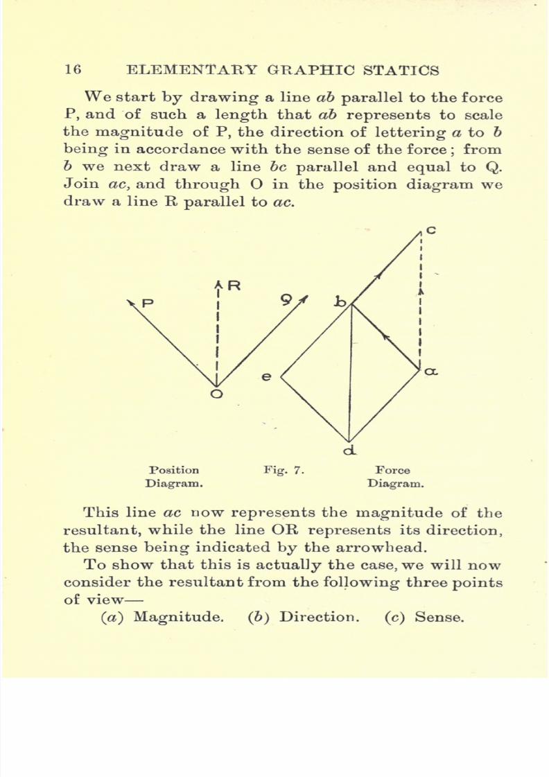
We start
by drawinga line ab
parallelto the force
P, and of such a length that ab represents to scale
the magnitude of P, the direction of lettering a to b
being in accordance with the sense of the force;from
b we next draw a line be parallel and equal to Q.
Join ac, and through in the position diagram we
draw a line Rparallel
to ac.
Position
Diagram.
Fig. 7. Force
Diagram.
This line ac now represents the magnitude of the
resultant, while the line OR represents its direction,
the sense being indicated by the arrowhead.
To show that this is actually the case, we will now
consider the resultant from the following three points
of view
(a) Magnitude, (b) Direction. (c) Sense.
7/29/2019 Elementary Graphi 00wighrich
http://slidepdf.com/reader/full/elementary-graphi-00wighrich 33/256
RESOLUTION OF FORCES 17
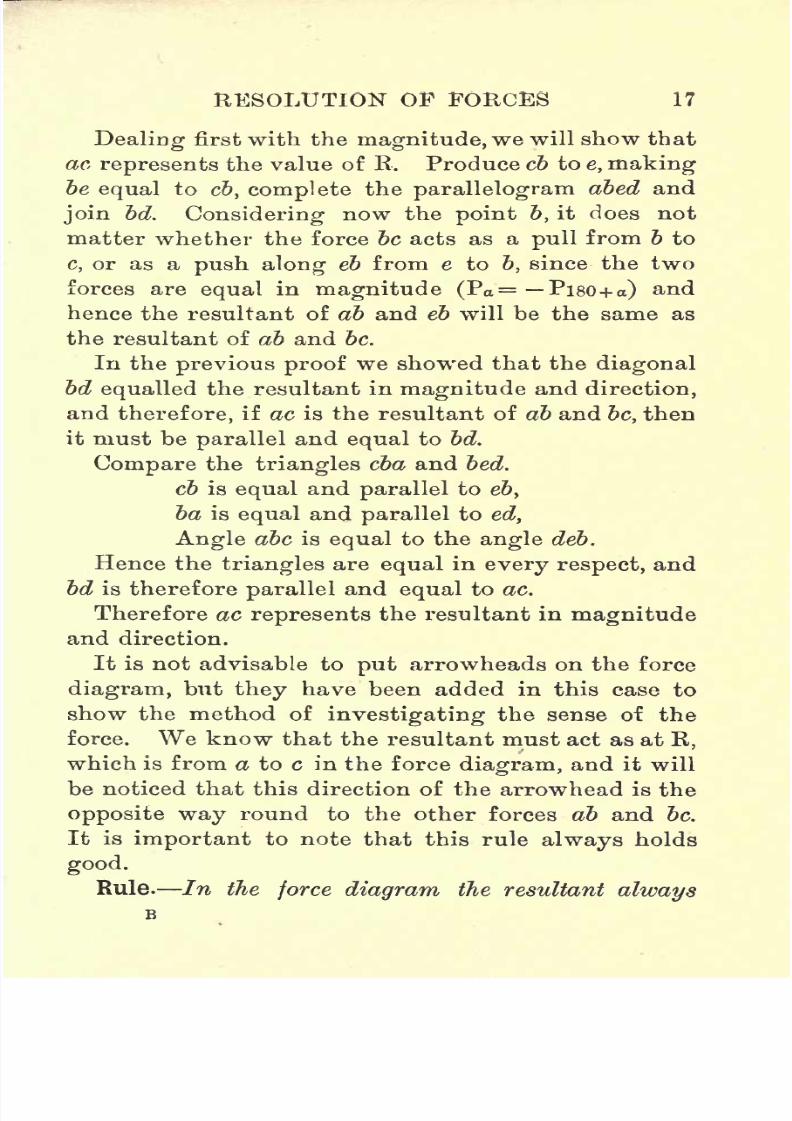
Dealingfirst with the
magnitude,we will show that
ac represents the value of B. Produce cb to e, makingbe equal to cb, complete the parallelogram abed and
join bd. Considering now the point 6, it does not
matter whether the force be acts as a pull from b to
c, or as a push along eb from e to b, since the two
forces are
equal
in
magnitude (Pa= Pi80 + a) and
hence the resultant of ab and eb will be the same as
the resultant of ab and be.
In the previous proof we showed that the diagonal
bd equalled the resultant in magnitude and direction,
and therefore, if ac is the resultant of ab and be, then
it must be parallel and equal to bd.
Compare the triangles cba and bed.
cb is equal and parallel to eby
ba is equal and parallel to ed,
Angle abc is equal to the angle deb.
Hence the triangles are equal in every respect, and
bd is therefore parallel and equal to ac.
Therefore ac represents the resultant in magnitudeand direction.
It is not advisable to put arrowheads on the force
diagram, but they have been added in this case to
show the method of investigating the sense of the
force. We know that the resultant must act as at B,
which is from a to c in the force diagram, and it will
be noticed that this direction of the arrowhead is the
opposite way round to the other forces ab and be.
It is important to note that this rule always holds
good.
Rule. In the force diagram the resultant always
7/29/2019 Elementary Graphi 00wighrich
http://slidepdf.com/reader/full/elementary-graphi-00wighrich 34/256
18 ELEMENTARY GftAPHIC STATICS
points
the oppositeway
round to the other forces, while
the equilibrant points the same way round.
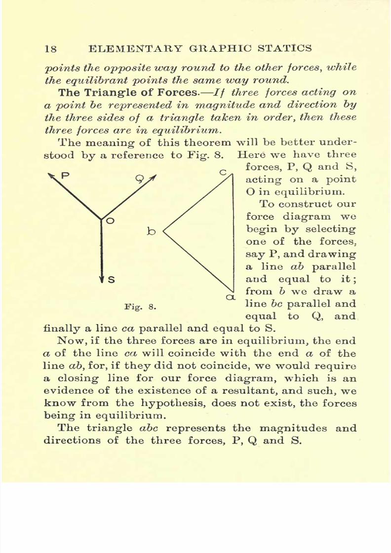
The Triangle of Forces.// three forces acting on
a point be represented in magnitude and direction by
the three sides of a triangle taken in order, then these
three forces are in equilibrium.
The meaning of this theorem will be better under-
ostood by a reference to Fig. 8. Here we have three
forces, P, Q and S,
acting on a point
in equilibrium.
To construct our
force diagram we
begin by selecting
one of the forces.
say P, and drawing
a line ab parallel
and equal to it;
from b we draw a
line be parallel and
equal to Q, and
finally a line ca parallel and equal to S.
Now, if the three forces are in equilibrium, the end
a of the line ca will coincide with the end a of the
line ab, for, if they did not coincide, we would require
a closing line for our force diagram, which is an
evidence of the existence of a resultant, and such, we
know from the hypothesis, does not exist, the forces
being in equilibrium.
The triangle abc represents the magnitudes and
directions of the three forces, P, Q and S.
Fig. 8.
7/29/2019 Elementary Graphi 00wighrich
http://slidepdf.com/reader/full/elementary-graphi-00wighrich 35/256
tlilSOLtfTION OF FORCES 19
The phrase taken in order means that the arrow-heads indicating the sense of the forces follow each
other in sequence round the sides of the triangle, and
it is worth noting that the direction of lettering,
which is coincident with the sense of the forces, also
follows round the triangle in order.
It is
importantto notice the fact
that,if three
forces act on a body in equilibrium, their directions
must be concurrent. Considering P and Q, we know
that their resultant must pass through O, and since the
forces are in equilibrium the force S must form the
equilibrant of P and Q, and must also pass through 0.
Anyone force is the
equilibrantof the other two.
The foregoing theorem is, however, only a particular
case of a more general theorem, known as
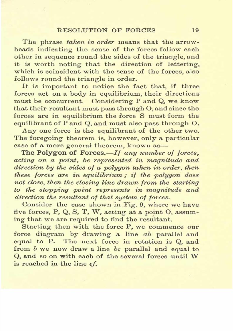
The Polygon of Forces.// any number of forces,
acting on a point, be represented in magnitude and
direction by the sides of a polygon taken in order, then
these
forcesare in
equilibrium; if
the
polygondoes
not close, then the closing line drawn from the starting
to the stopping point represents in magnitude and
direction the resultant of that system of forces.
Consider the case shown in Fig. 9, where we have
five forces, P, Q, S, T, W, acting at a point 0, assum-
ing
that we are
required
to find the resultant.
Starting then with the force P, we commence our
force diagram by drawing a line ab parallel and
equal to P. The next force in rotation is Q, and
from b we now draw a line be parallel and equal to
Q, and so on with each of the several forces until Wis reached in the line
ef.
7/29/2019 Elementary Graphi 00wighrich
http://slidepdf.com/reader/full/elementary-graphi-00wighrich 36/256
20 ELEMENTARY GRAPHIC STATICS
Should the end / of the line ef coincide with theend a of the line ab, we would then have a closed
figure, and the five forces, P, Q, S, T, W, would be in
equilibrium.
If, however,/ does not fall on a, we join af and
through O in our position diagram draw a line
parallel to af.
This line now represents the line of action of the
Fig. 9.
resultant R, while the length af represents its magni-
tude, its sense being found by following the forces
round the force diagram.
Note. It is immaterial in what order the forcesare taken, as can be easily proved by drawing out
several polygons and comparing results, but, although
this is the case, it is advisable to cultivate some
system of orderliness in tackling such problems ;the
habit thus formed will obviate much worry and con-
fusion when dealing with more intricate problems,
7/29/2019 Elementary Graphi 00wighrich
http://slidepdf.com/reader/full/elementary-graphi-00wighrich 37/256
RESOLUTION OF FORCES 21
Resolution of Forces. The two general cases just
given provide a means of solving all problems in-
volving the composition of concurrent forces. The
various operations are simply reversed in the applica-
tion of these constructions to problems dealing \vith
the resolution of forces.
It is
hardly necessary to deal very fully with this
part of the subject, as the restrictions imposed on the
solutions reduce the problems, in general, to exercises
in simple geometry.
In general, whether resolving into two forces or
any number of forces, we are reduced to four par-
ticular cases.
We haveto find
oneor
otherof
thefollowing :
(a) Direction and magnitude of one force.
(&) Direction of one and magnitude of the other.
(c) Directions of two forces.
(d) Magnitudes of two forces.
Thiscan
beexpressed generally
thus : If
n be thenumber of forces acting at a point, then to specify
the forces at the point we must know 2n facts about
the forces, e.g.,n magnitudes and n directions. It is
only possible to solve the problem if (2n 2) facts
are known about the given forces.
Probablythe method of
dealingwith such
problemswill be most easily understood by an examination of
a few particular cases worked out to scale and dealing
with all the cases mentioned in the previous pages.
Examples worked out.
1. A weight of 500 Ibs. is hung by two cords, oy
and oz, which makeangles
of 50 and 150respectively,
7/29/2019 Elementary Graphi 00wighrich
http://slidepdf.com/reader/full/elementary-graphi-00wighrich 38/256
22 ELEMENTARY GRAPHIC STATICS
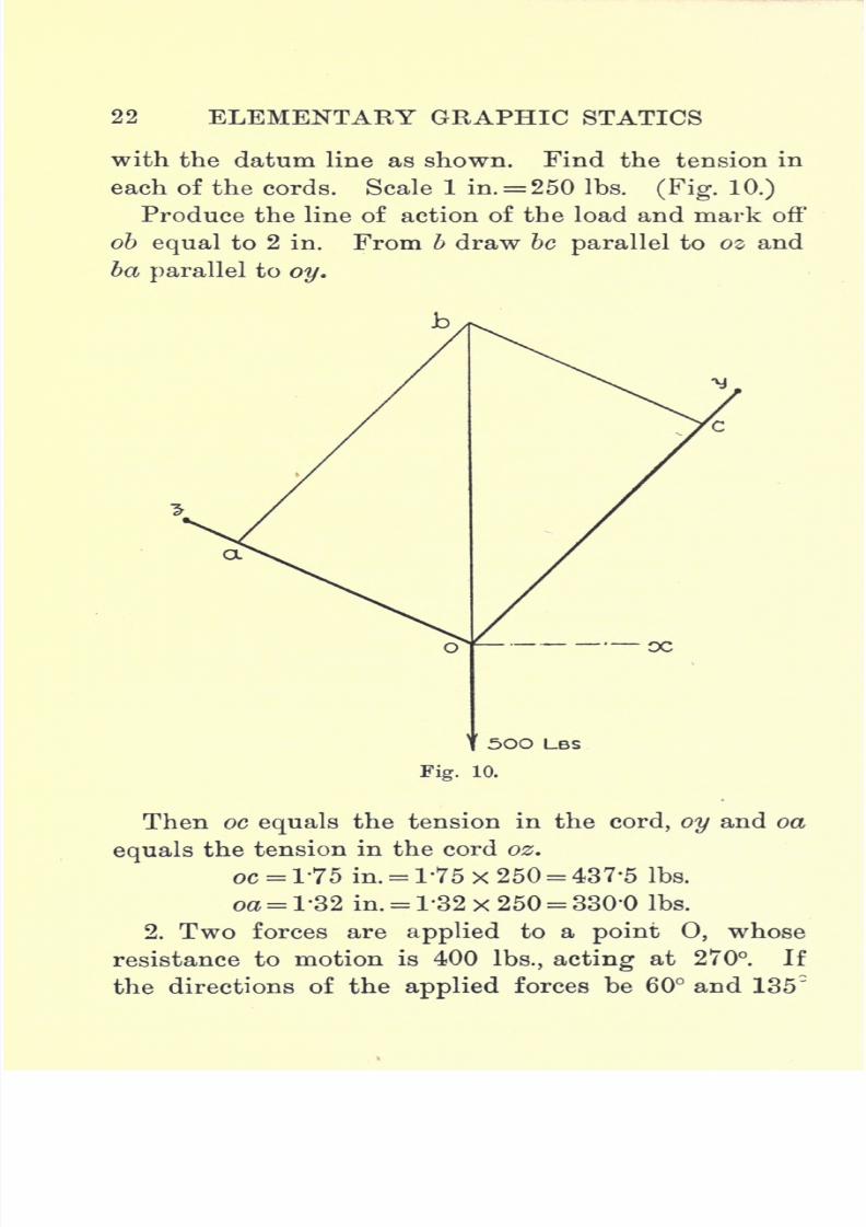
with the datum line as shown. Find the tension in
each of the cords. Scale 1 in.= 250 Ibs. (Fig. 10.)
Produce the line of action of the load and mark off
ob equal to 2 in. From b draw be parallel to oz and
ba parallel to oy.
500 LBS
Fig. 10.
Then oc equals the tension in the cord, oy and oa
equals the tension in the cord oz.
oc = 175 in. = 1-75 x 250 = 437*5 Ibs.
oa= 1-32 in. = T32 x 250 = 330'0 Ibs.
2. Two forces are applied to a point 0, whose
resistance to motion is 400 Ibs., acting at 270. If
the directions of the applied forces be 60 and 135"

7/29/2019 Elementary Graphi 00wighrich
http://slidepdf.com/reader/full/elementary-graphi-00wighrich 39/256
RESOLUTION OF FORCES 23
respectively, find the value of each force when motion
just takes place ? Scale 1 in. = 200 Ibs. (Fig. 1L.)
When motion just takes place, the resistance of
400 Ibs. has just been overcome, so that the point is
in equilibrium under three forces, viz. : A resistance
of 400 Ibs., acting away from 0, and two forces P
and Q, acting awayin the opposite direc-
tions, as shown.
We begin by
drawing a line a&,
2 in. long, parallel
to
R;
from 6 a line
be parallel to P, and
from a a line parallel
to Q ;acb now re-
presents the triangle
of forces for the
point 0,and be and
ca represent the
forces P and Q re-
spectively.
bc= 1-05 in. = 1-05x200 = 210 Ibs.
ac= 1 -45 in. = 1 -45 x 200 =290 Ibs.
3. Five menpull
on a
bodyas
shown,each with a
force of 30 Ibs. It is proposed to apply, by means
of a tackle, a single force, to have the same effect as
that of the five men. Find the position of the tackle
and the force which it must be capable of exerting.
Scale 1 in.= 60 Ibs. (Fig. 12.)
Webegin by drawing
a line ab,J
in.
long, parallel
Fig- 11.
7/29/2019 Elementary Graphi 00wighrich
http://slidepdf.com/reader/full/elementary-graphi-00wighrich 40/256
24 ELEMENTARY GRAPHIC STATICS
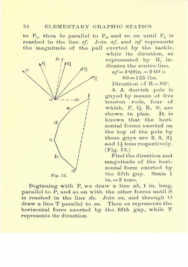
to Plf then be parallel to P2 , and so on until P5 is
reached in the lineef.
Join a/, and af represents
the magnitude of the pull exerted by the tackle,
while its direction, as
represented by R, in-
dicates the centre-line.
a/=2-09in.= 2-09x60= 125 Ibs.
Direction of R = 83.
4. A derrick pole is
guyed by means of five
tension rods, four of
which, P, Q, R, S, are
shown in plan. It is
known that the hori-
zontal forces exerted on
the top of the pole by
these guys are 2, 3, 2J
and 1 J tons respectively.
(Fig. 13.)
Find the direction and
magnitude of the hori-
zontal force exerted by
the fifth guy. Scale 1
in.= 2 tons.
Beginning with P, we draw a line a&, 1 in. long,
parallel to P, and so on with the other forces until S
is reached in the line de. Join ea, and through
draw a line T parallel to ea. Then ea represents the
horizontal force exerted by the(
fifth guy, while T
represents its direction.
Fig. 12.

7/29/2019 Elementary Graphi 00wighrich
http://slidepdf.com/reader/full/elementary-graphi-00wighrich 41/256
RESOLUTION OF FORCES 25
ea = l'38 in.= l-38x 2= 2-76 tons.
Direction of guy = 301.
5. The point is the plaii of a telegraph pole,
from which six lines of wire radiate. The positions
of four of them are indicated by the lines, P, Q, R, S,
the tensions in each being 20 Ibs. It is known,
regarding the other two lines, that one of them is
inclined at 180, while the other is in tension to the
extent of 30 Ibs. If O be in equilibrium, determine
7/29/2019 Elementary Graphi 00wighrich
http://slidepdf.com/reader/full/elementary-graphi-00wighrich 42/256
26 ELEMENTARY GRAPHIC STATICS
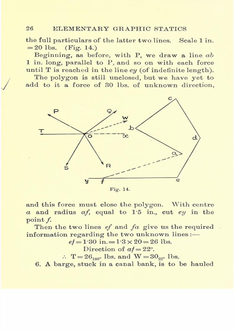
the full particulars of the latter two lines. Scale 1 in.
= 201bs. (Fig. 14.)
Beginning, as before, with P, we draw a line ab
1 in. long, parallel to P, and so on with each force
until T is reached in the line ey (of indefinite length).
The polygon is still unclosed, but we have yet to
add to it a force of 30 Ibs. of unknown direction,
Fig. 14.
and this force must close the polygon. With centre
a and radius a/, equal to 1*5 in., cut ey in the
point /.Then the two lines ef and fa give us the required
information regarding the two unknown lines :
e/= l'30 in.= 1-3x20 = 26 Ibs.
Direction of af= 22.
.-. T = 26180
o Ibs. and W = 3022
o Ibs.
6, Abarge,
stuck in a canal bank, is to be hauled
7/29/2019 Elementary Graphi 00wighrich
http://slidepdf.com/reader/full/elementary-graphi-00wighrich 43/256
RESOLUTION OF FORCES 27
6OO LBS.
off
bymeans of two winches
placed
on the
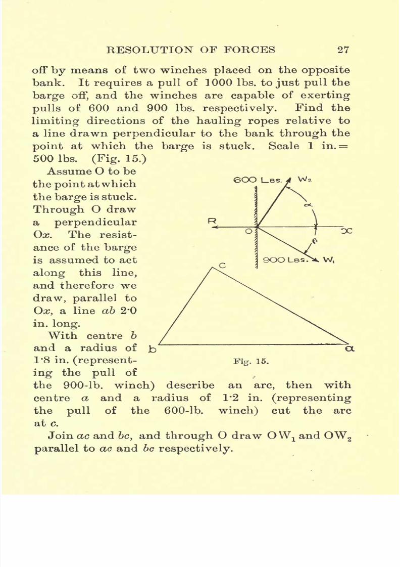
oppositebank. It requires a pull of 1000 Ibs. to just pull the
barge off, and the winches are capable of exerting
pulls of 600 and 900 Ibs. respectively. Find the
limiting directions of the hauling ropes relative to
a line drawn perpendicular to the bank through the
point
at which the
barge
is stuck. Scale 1 in.=
500 Ibs. (Fig. 15.)
Assume O to be
the point at which
the barge is stuck.
Through O draw
a
perpendicularOx. The resist-
ance of the barge
is assumed to act
along this line,
and therefore we
draw, parallel to
Ox, a line ab 2*0
in. long.
With centre b
and a radius of b~ CX
1*8 in. (represent- Fig. 15.
ing the pull of
the 900-lb. winch) describe an arc, then with
centre a and a radius of 1*2 in. (representing
the pull of the 600-lb. winch) cut the arc
at c.
Join ac and be, and through draw OWj and OW2
parallel to ac and berespectively.

7/29/2019 Elementary Graphi 00wighrich
http://slidepdf.com/reader/full/elementary-graphi-00wighrich 44/256
28 ELEMENTARY GRAPHIC STATldS
These lines now represent the directions of the
ropes
Rope of small winch at 61 =.
Rope of large winch at 36 =/3.
7. If, in the previous question, the positions of the
winches were such that the ropes were inclined to
Ox at
angles
of 30 and 50
respectively,
what would
have been the minimum power of the winches
necessary to give a pull of 1000 Ibs. on the barge ?
Scale 1 in. = 500 Ibs.
Set out a line ab, 2'0 in. long, parallel to Ox;
through b draw be parallel to Wlfand through a
draw ac parallel to W2
.
Then ac and be represent the pulls exerted by the
winches W2and W
l respectively.
ac= T05 in. = 1-05x500= 525 Ibs.
6c = l-57 hi. = 1-57x500 = 785 Ibs.
Therefore winches must be capable of exerting
pulls
of 785 and 525 Ibs. respectively.
Bow's Notation. In nearly all our problems we
deal with two kinds of diagrams, viz., position dia-
grams and force diagrams.
In the position diagram, which is drawn to some
space scale, the lines only indicate the directions of
the forces, while, on the other hand, in the force
diagram, which is drawn to some force scale, the
lines represent the magnitudes of the forces acting at
the corresponding points in the position diagram.
In passing thus from one diagram to the other, it
is essential that we have some method of lettering
common to both,yet
distinct in each. The method

7/29/2019 Elementary Graphi 00wighrich
http://slidepdf.com/reader/full/elementary-graphi-00wighrich 45/256
RESOLUTION OF FORCES 29
which is
probablythe best is Bow's
(sometimesknown as Henrici's) notation. This method of
lettering is extremely useful in dealing with forces
in equilibrium, as in the case of the forces in the
various members of a roof truss or braced girder,
but it is not advisable to use it in the solution of
problems
such as we have dealt with in the preced-
ing pages. Possibly the best method of explaining
the notation would be to consider an actual case.
Consider the case of the four forces, P, Q, S and T,
acting on the point O being in equilibrium.
Instead of naming the forces, as we have done, P, Q,
S, T, we put a capital letter on either side of the
7/29/2019 Elementary Graphi 00wighrich
http://slidepdf.com/reader/full/elementary-graphi-00wighrich 46/256
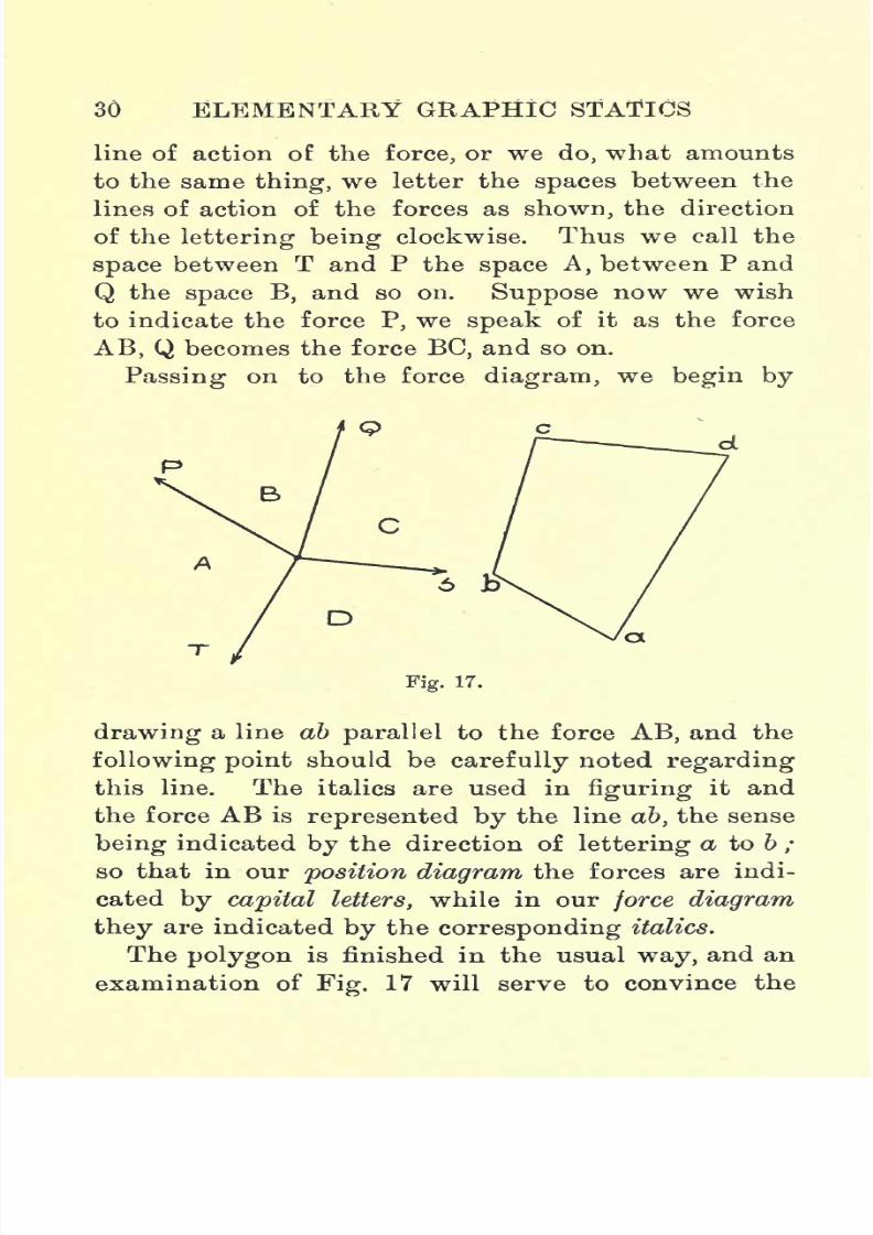
30 ELEMENTARY GRAPHIC STATICS
line of action of the force, or we do, what amounts
to the same thing, we letter the spaces between the
lines of action of the forces as shown, the direction
of the lettering being clockwise. Thus we call the
space between T and P the space A, between P and
Q the space B, and so on. Suppose now we wish
to indicate the forceP,
wespeak
of it as the force
AB, Q becomes the force BC, and so on.
Passing on to the force diagram, we begin by
Fig. 17.
drawing a line ab parallel to the force AB, and the
following point should be carefully noted regarding
this line. The italics are used in figuring it and
the force AB is represented by the line ab, the sense
being indicated by the direction of lettering a to b ;
so that in our position diagram the forces are indi-
cated by capital letters, while in our force diagram
they are indicated by the corresponding italics.
The polygon is finished in the usual way, and an
examination of Fig. 17 will serve to convince the
7/29/2019 Elementary Graphi 00wighrich
http://slidepdf.com/reader/full/elementary-graphi-00wighrich 47/256
RESOLUTION OF FORCES 3l
student of the extremeutility
of this
systemof
lettering.
Examples.
1. Forces of 32 Ibs. and 24 Ibs. act on a point in
such a way that the angle between their lines of
action is 73. Determine the magnitude of the re-
sultant force.
2. A body is acted on by two forces, P and Q.
P is equal to 90 Ibs. and acts at an angle of 28 to
the datum-line, while Q is equal to 72 Ibs. and acts
at 103. Determine the magnitude and direction of
that force which would just prevent being moved
by the forces P and Q.
3. A chain-sling, 18 ft. long, is used to lift a
casting, weighing 45 tons. The ends of the sling
are attached to eyebolts on the casting at horizontal
points 3 ft. 6 in. apart. Determine the pull in the
chain when the casting is suspended by the chain.
4. Four forces, P, Q, S, T, act on a point and keep
it in equilibrium. It is known that the values of
P and Q are 200 and 280 Ibs. respectively, while the
angles at which they act are 30 and 110 respectively.
S and T act at 220 and 280 respectively. Deter-
mine the magnitudes of the latter two forces.
5. A girder, weighing 30 tons, is hanging from a
crane, the length of the suspending rope being
26 ft. It is found necessary to deflect the girder
horizontally through a distance of 3 ft. Deter-
mine the horizontal force necessary to accomplish
this amount of horizontal deflection.
6. A barge is being pulled along a canal by means
7/29/2019 Elementary Graphi 00wighrich
http://slidepdf.com/reader/full/elementary-graphi-00wighrich 48/256
32 ELEMENTARY GRAPHIC STATICS
of a
tow-rope.
Thebarge
is 34 ft. from the bank
while the horse is 5 ft. from the edge of the bank.
The tow-rope, is 64 ft. long. The horse exerts a
pull of 140 Ibs. Determine the resistance to motion
per ton if the loaded barge weighs 25 tons.
7. A steel chimney is 20 ft. high and 30 in.
diameter. It is
guyed byfour wire
ropes runningnorth, south, east and west. The ropes are attached
to a strap 10 ft. up from the ground and slope at an
angle of 34 with the ground. A north wind blows
with a force of 30 Ibs. per sq. ft. of ^projected
area. Determine the pull in the north guy, assum-
ingit
takingall the load. What would be the
pullin the north and east guys, with a north-easterly
wind of intensity equal to 40 Ibs. per sq. ft. ?

7/29/2019 Elementary Graphi 00wighrich
http://slidepdf.com/reader/full/elementary-graphi-00wighrich 49/256
CHAPTER III
PRACTICAL PROBLEMS
HAVING now discussed the principles involved in
the solution of the simpler general problems in
Graphic Statics, we will now proceed to consider
the application of these principles to a few simple
problems commonly met with in practice.
Loaded Platform. In Fig. 18 is illustrated a uni-
formly loaded platform HP, which is hinged at H,
and held in its horizontal position by means of two
tie-rods FP, one at either end of the platform. In
this case suppose we let
L= the length of the platform in ft.
B = the breadth of the platform in ft.
w = load per sq, ft. in Ibs.
W = total load carried.
Then W = LxBxw? Ibs.
We have assumed the load in this case to be uni-
formly distributed, and hence W can be taken to act
through the centre of area of the platform. Bisect
HP in the point K and through K raise a vertical to
cut FP in the point O. Now the platform is acted
on by three forces which keep it in equilibrium, viz. :
the load W, the tension in the tie-rods and R, the
reaction at the hinge. We have seen that when we
c 33

7/29/2019 Elementary Graphi 00wighrich
http://slidepdf.com/reader/full/elementary-graphi-00wighrich 50/256
34 ELEMENTARY GRAPHIC STATICS
have a
bodyacted on
bythree forces, which
keepit
in equilibrium, then these three forces must pass
through a common point. The load W and the
tension T meet in 0, hence the hinge reaction must
also pass through this point. By drawing a line to
pass through H and
O weget
the line of
action of the reaction.
This now completes
the position diagram,
from which it is
a simple matter to
obtain the force dia-
gram and determine
the magnitude of the
required forces. Set
down, to scale, a line
ab to represent the
load
W;from b draw
be parallel to R, and
from a draw ac parallel to T. The triangle dbc
gives the force diagram from which we can scale off
the forces in the tie-rods and at the hinge.
Note. Tension in each tie-rod= =^- Ibs.
2 2
Triangular Frame. A triangular frame ABC is
supported at A by a hinge and at C by a rope which
passes over a pulley D. At B a load W is attached.
Determine the pull in the rope and the reaction at
the hinge. Produce the line of action of the rope at
C until it cuts BW in O;draw a line to
pass through

7/29/2019 Elementary Graphi 00wighrich
http://slidepdf.com/reader/full/elementary-graphi-00wighrich 51/256
PRACTICAL PROBLEMS 35
w
Fig. 19.
A and O. Produce
OBand mark off 06 to
representW, to scale. From b draw ba parallel to 00 and be
parallel to OA. Then
Oa measured to scale
gives the magnitude of
the reaction at A, while
Ocgives
the tension
in the rope.
Shear Legs. The
shear legs, shown in
Fig. 20, as used for lift-
ing heavy loads, intro-
duces one or two points
of interest. The ar-
rangement consists of
two struts, as shown
by the member OB, and a back-tie, as shown
by AC. In the first part of the problem we
make use of the triangle of forces to determine
the magnitude of the pull in the tie AC, and the
thrust which is sustained by the two struts. Set
down ab to represent W and complete the triangle
of forces abc. The line ac gives the pull in the back-
tie, while be gives the thrust sustained by the two
struts. This latter thrust acts along a centre-line
between the struts, and we have now to determin
how this thrust is sustained. In order to see how
this force be acts with respect to the struts, we must
first obtain an elevation looking in the direction of
the arrow H. From B, the foot of the strut, raise a
perpendicular ;with centre B swing round the strut
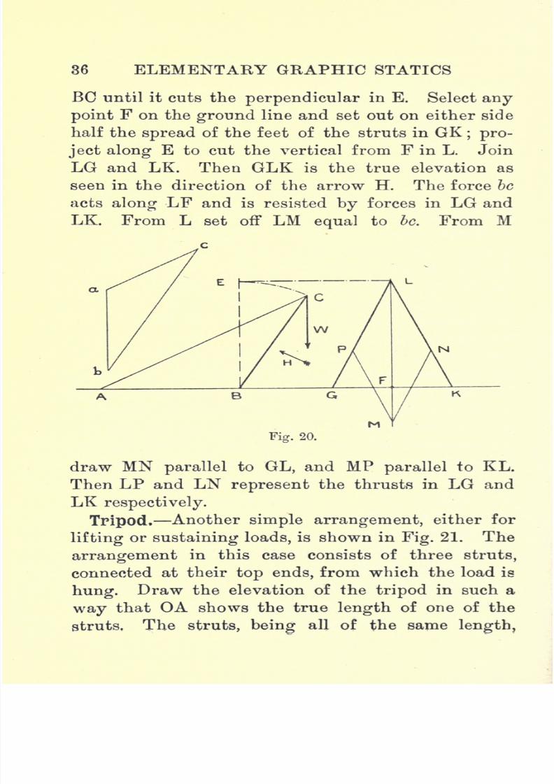
7/29/2019 Elementary Graphi 00wighrich
http://slidepdf.com/reader/full/elementary-graphi-00wighrich 52/256
36 ELEMENTARY GRAPHIC STATICS
BC until it cuts theperpendicular
in E. Select
anypoint F on the ground line and set out on either side
half the spread of the feet of the struts in GK; pro-
ject along E to cut the vertical from F in L. Join
LG and LK. Then GLK is the true elevation as
seen in the direction of the arrow H. The force be
acts
alongLF and is resisted
byforces in LG and
LK. From L set off LM equal to be. From M
3k L
Fig. 20.
draw MN parallel to GL, and MP parallel to KL.
Then LP and LN represent the thrusts in LG and
LK respectively.
Tripod.
Anothersimple arrangement,
either for
lifting or sustaining loads, is shown in Fig. 21. The
arrangement in this case consists of three struts,
connected at their top ends, from which the load is
hung. Draw the elevation of the tripod in such a
way that OA shows the true length of one of the
struts, The struts,
being
all of the samelength.

7/29/2019 Elementary Graphi 00wighrich
http://slidepdf.com/reader/full/elementary-graphi-00wighrich 53/256
PRACTICAL PROBLEMS
makeequal angles
withground
andcentre-line
and
hence each one sustains a load proportional to one-
third of the total load. Mark off on the centre line
Wa length Oa equal to -
; project ab horizontally too
cut OA in b. Then Ob represents the thrust in each
of the legs.
Simple Crane with Sus-
pended Load Fig. 22 shows
a very simple type of crane,
in which the load is lifted bya tackle suspended from the
outmost point of the jib. It
is required to find the thrust
in the jib BC and the pull
in the tie AC (Bow's nota-
tion). Set down ab to re-
present W, from b draw be
parallel to BC, and from a
draw ac parallel to AC.
Then be gives the thrust in
the jib, while ac gives the
pull in the tie-rod.
Simple Crane with Single
Chain Lift Fig. 23 shows
a modification of the crane in the previous ques-
tion. The load, in this case, is lifted by a chain
which passes over a pulley at the end of the jib,
running back parallel to the tie-rod and passing over
another pulley at the top of the mast. Set down ab
to represent W ;from b draw be parallel to BC. We
Fig. 21.

7/29/2019 Elementary Graphi 00wighrich
http://slidepdf.com/reader/full/elementary-graphi-00wighrich 54/256
38 ELEMENTARY GRAPHIC STATICS
have now two forces acting at the jib-end, namely,
the pull in the tie-rod CD and the pull in the chain
DA. Concerning these two forces we know the
following facts the pull in the chain has a magni-
tude, W, its direction is parallel to the tie-rod, and it
acts away from the jib-end; while, regarding the
force in the tie-rod, we only know that it acts along
CD. We can therefore continue our force diagram
by drawing from a a line ad parallel to the chain and
having a magnitude equal to W. The force diagram
can now be completed by drawing from d a line
parallel to DC cutting be in the point c.
The student, in solving this problem, should use
the same configuration and load as in the previous
example, and note that the thrust in the jib is the
same in each case, while in the second case the pull
on the tie-rod is reduced by W.
Simple Crane with Double Chain Lift The out-
7/29/2019 Elementary Graphi 00wighrich
http://slidepdf.com/reader/full/elementary-graphi-00wighrich 55/256
PRACTICAL PROBLEMS 39
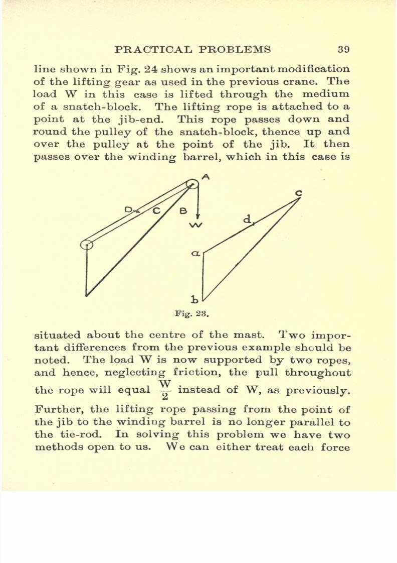
line shown in
Fig.
24 shows animportant
modification
of the lifting gear as used in the previous crane. The
load W in this case is lifted through the medium
of a snatch-block. The lifting rope is attached to a
point at the jib-end. This rope passes down and
round the pulley of the snatch-block, thence up and
over the pulley at the point of the jib.It then
passes over the winding barrel, which in this case is
situated about the centre of the mast. Two impor-
tant differences from the previous example should be
noted. The load W is now supported by two ropes,
and hence, neglecting friction, the pullthroughoutWthe rope will equal instead of W, as previously.
Further, the lifting rope passing from the point of
the jib to the winding barrel is no longer parallel to
the tie-rod. In solving this problem we have two
methods open to us. We can either treat each force

7/29/2019 Elementary Graphi 00wighrich
http://slidepdf.com/reader/full/elementary-graphi-00wighrich 56/256
40 ELEMENTARY GRAPHIC STATICS
separately, or we can find the resultant force at the
jib-point due to the magnitude and direction of the
pulls in the various ropes. Taking each force sepa-
rately, we first set down abbc to represent the pulls
at the jib-point caused by the two rope falls. It will
Wreadily be seen that ab= bc = . From c we now
draw cd parallel to CD, but we cannot, as yet, fix the
d
point d, since we do not know the magnitude of the
stress in CD. We, however, know both the magnitude
and the direction of the pull in AE, and we can
therefore draw from a a line ae parallel to AE and of
Wmagnitude equal to (the constant tension in the
2i
rope). From e we can finally draw ed parallel to ED,
and so complete the force diagram. The stresses in
the jib and tie-rod can then be scaled off from the
diagram.
7/29/2019 Elementary Graphi 00wighrich
http://slidepdf.com/reader/full/elementary-graphi-00wighrich 57/256
PRACTICAL PROBLEMS 41
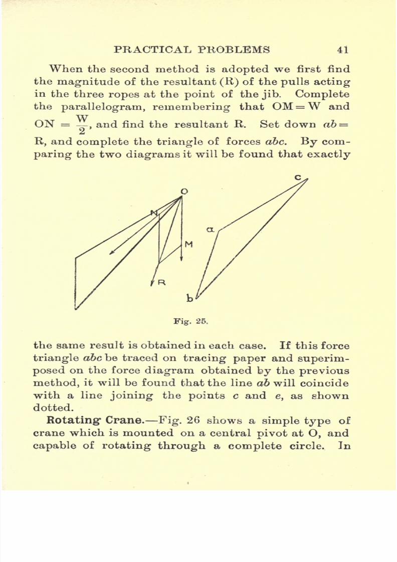
When the second method is
adoptedwe first find
the magnitude of the resultant (R) of the pulls acting
in the three ropes at the point of the jib. Complete
the parallelogram, remembering that OM =W and
ON =,and find the resultant R. Set down ab =
R, and complete the triangle of forces abc. By com-
paring the two diagrams it will be found that exactly
Fig. 25.
the same result is obtained in each case. If this force
triangle abc be traced on tracing paper and superim-
posed on the force diagram obtained by the previous
method, it will be found that the line ab will coincide
with a line joining the points c and e, as shown
dotted.
Rotating: Crane. Fig. 26 shows a simple type of
crane which is mounted on a central pivot at 0, and
capable of rotating through a complete circle. In

7/29/2019 Elementary Graphi 00wighrich
http://slidepdf.com/reader/full/elementary-graphi-00wighrich 58/256
42 ELEMENTAKY GRAPHIC STATICS
order to maintain equilibrium when lifting the load
W, it is necessary to apply a balance weight Wxof
such a magnitude that the moment of Wxabout O
will just neutralize the moment of W about O. The
solution of this problem should present no difficulty
if the joints be taken in the following order point
of jib, head of mast, outer end of lower member DE.
Fig. 26.
Notice that ea gives the magnitude of the balance
weight Wr
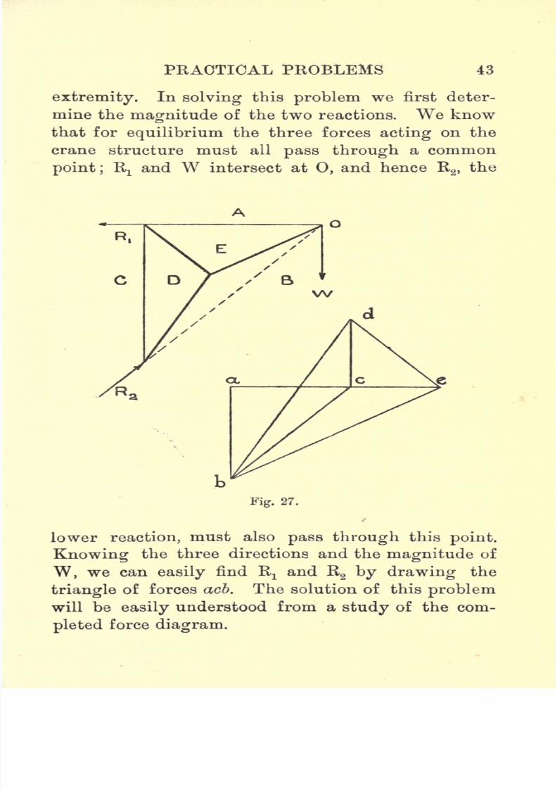
Warehouse Crane. Fig. 27 shows a simple ware-
house crane as fitted with a lifting tackle hungfrom the point of the jib. This crane is capable of
swinging through a considerable angle, being mounted
on a pivot bearing at the lower extremity of the post
CD, and fitted with a simple bearing at the upper
extremity. This upper bearing exerts only a hori-
zontal force on the post, while the lower pivot exerts
both a vertical and a horizontal force on its lower
7/29/2019 Elementary Graphi 00wighrich
http://slidepdf.com/reader/full/elementary-graphi-00wighrich 59/256
PRACTICAL PROBLEMS 43
extremity.
Insolving
this
problemwe first deter-
mine the magnitude of the two reactions. We know
that for equilibrium the three forces acting on the
crane structure must all pass through a common
point; Rxand W intersect at 0, and hence R
2 ,the
Fig. 27.
lower reaction, must also pass through this point.
Knowing the three directions and the magnitude of
W, we can easily find Rxand R
2 by drawing the
triangle of forces acb. The solution of this problem
will be easily understood from a study of the com-
pleted force diagram.
7/29/2019 Elementary Graphi 00wighrich
http://slidepdf.com/reader/full/elementary-graphi-00wighrich 60/256
44 ELEMENTARY GRAPHIC STATICS
Examples.
1. A draw-bridge, 30 ft. long and 20 ft. wide, is
supported in a horizontal position in the maDner
shown in Fig. 18. The angle between the chains
and the beam is 56. Find the tension in each of
the chains and the reaction at the hinge when the
bridge is carrying a uniformly distributed load of
120 Ibs. per sq. ft.
2. A small crane consists of a beam 10 ft. long,
hinged at its inner end. The outer end is supported
by a steel wire-rope, which is attached to the wall
at a point 8 ft. above the hinge. A load of 4 tons is
lifted by means of a tackle, attached to a point 3 ft.
from the outer end. Find the reaction at the hinge
and the pull in the rope.
3. A gate, 4 ft. high and 6 ft. wide, is carried on
two hinges, the lower one at the bottom right-hand
corner taking all the vertical load. The hinges are
3 ft. 6 in.
apart.
Determine the
magnitudesand
directions of the reactions at the hinges if the gate
weighs 200 Ibs.
4. A set of shear legs is used to place a boiler on
its seating. The legs are each 40 ft. long and the
spread of the feet 28 ft. 6 in. The plane containing
the struts makes anangle
of 70 with the
groundline and the back tie is 54 ft. long. Find the pull
in the tie and the thrust in each of the legs if the
boiler weighs 16 tons.
5. A tripod, consisting of three struts, each 30 ft.
long, is used to lift a steam-engine cylinder weighing
2 '4 tons. The struts make equal angles with the

7/29/2019 Elementary Graphi 00wighrich
http://slidepdf.com/reader/full/elementary-graphi-00wighrich 61/256
PRACTICAL PROBLEMS 45
ground, andtheir
lower extremitieslie
on a circle12
feet diam. Find the thrust in the struts.
6. A crane similar to that shown in Fig. 22 has
the following dimensions : Mast, 10 ft.; jib, 28 ft.;and
tie, 21 ft. Determine the pull in the tie and the
thrust in the jib when lifting a load of 4 tons.
(a) Simple case,as in
Fig.22.
(6) With chain lift, as in Fig. 23.
(c) With snatch-block, as in Fig. 24, the lifting
barrel being 4 ft. from the foot of the
mast.
7. A revolving crane, as shown in Fig. 26, has the
followingdimensions:
Mast,10
ft.;
centre of mast
to centre of load, 20 ft.;centre of mast to centre of
balance weight, 12 ft.; point of jib, 18 ft. above the
ground level. Determine and tabulate the stresses in
the various members when lifting a load of 10 tons.
8. A warehouse crane, of the type shown in Fig.
27, is used for
lifting
bales
upto a maximum of 30
cwts. Determine the stresses in the members if the
crane has the following proportions: AE=CD =12 ft., and DE= 7 ft. Determine also the reactions
R! and R2
.
7/29/2019 Elementary Graphi 00wighrich
http://slidepdf.com/reader/full/elementary-graphi-00wighrich 62/256
CHAPTER IV
COMPOSITION OF NON-CONCURRENT FORCES
The Funicular Polygon. So far, we have been
dealing only with concurrent forces, but we shall now
proceed to investigate the case in which the several
forces have not a common point of application.
In dealing with concurrent forces we saw that the
one condition necessary for equilibrium was that
the force polygon should close, but, in dealing with
non-concurrent forces, a further condition must be
satisfied, namely, the funicular polygon must also
close.
Before investigating the latter condition, it might
be well to explain the term "funicular polygon."
The word " funicular " has its derivation in a Latin
word "funis" meaning a
"cord" and the funicular or
link polygon represents the shape which would be
assumed by an endless cord, were it subjected to the
given system of forces.
In many cases the forces acting in the various
links of the funicular polygon are in the nature
of compression. As is well known, a string cannot
transmit a compression, and hence the general use of
the term funicular polygon is hardly appropriate.
The term is retained principally for convenience, and
has now only a geometrical significance.
7/29/2019 Elementary Graphi 00wighrich
http://slidepdf.com/reader/full/elementary-graphi-00wighrich 63/256
NON-CONCURRENT FORCES 47
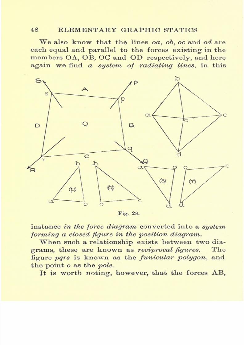
In dealing with this case, let us consider the general
example shown in Fig. 28, in which we have four
forces, P, Q, R and S, forming a system in equilibrium,
the figure pqrs being the shape assumed by the cord
under the action of the given system.
Beginning with the point p, we see that we have
here a point in equilibrium under the action of three
concurrent forces, OA. AB, and BO, and hence we can
represent these three forces by the sides of a triangle,
as explained in Chapter II. By treating each of the
four points p, q,r and s in the same way, we get four
triangles, aob, boc, cod and doa, and if we examine
them carefully we find a close relationship exists
among them;we find, for example, that ob in (p) is
equal and parallel to ob in (q) ; similarly with oc in
(q) and oc in(r) ;
with od in(r)
and od in(s) ;
with
oa in(s)
and oa in (p).
The positions of the separate triangles are, however,
quite arbitrary, and hence there is no reason why we
should not place them in such positions that they
will form a complete figure abed as shown. There
are now a few points in the two diagrams worthy of
comparison. We know that the lines ab, be, cd and
da are each equal and parallel to AB, BC, CD and
DA respectively, and therefore the figure abed is the
force polygon for the system. This figure forms a
closed figure, thereby satisfying one condition of
equilibrium, and it is worth noting that a system of
radiating lines in the position diagram has now
become, in the force diagram, a system forming a
closed figure.
7/29/2019 Elementary Graphi 00wighrich
http://slidepdf.com/reader/full/elementary-graphi-00wighrich 64/256
48 ELEMENTARY GRAPHIC STATICS
We also know that the lines oa, ob, oc and od are
each equal and parallel to the forces existing in the
members OA, OB, OC and OD respectively, and here
again we find a system of radiating lines, in this
Fig. 28.
instance in the force diagram converted into a system,
forming a closed figure in the position diagram.
When such a relationship exists between two dia-
grams, these are known as reciprocal figures. The
figure pqrs is known as the funicular polygon, and
the point c as the pole.
It is worth noting, however, that the forces AB,

7/29/2019 Elementary Graphi 00wighrich
http://slidepdf.com/reader/full/elementary-graphi-00wighrich 65/256
NON-CONCURRENT FORCES 49
BC, CD and DA are fixed in magnitude and direc-
tion, and hence we can have only one force polygon,
while the lengths of the links may vary, and conse-
quently we may have any number of funicular
polygons, and if we drew out a few different cases
we would find that, for this particular system of
forces, the figure abed would remain the same, while
the position of o would vary, both force and funi-
cular polygons always closing.
A little thought will show that the converse con-
struction will also hold good. Suppose, for example,
we have four non-concurrent forces in equilibrium,
and we wish to draw out the shape taken up by any
cord under the action of these forces. We would
begin by drawing out our force polygon, selecting a
pole o, to which we would join the angular points
of the polygon. We would then draw in the funi-
cular polygon with sides parallel to the radiating
lines in the force diagram, and we would find that
the funicular polygon formed a closed figure, each
corner of which fell on the line of action of one of
the forces.
Resultant of Non-concurrent Forces. This latter
construction, as just described, is the one we make
use of when finding the magnitude and direction of
the resultant of a system of non- concurrent forces, and
to make the application of this construction as clear
as possible, we will now consider the following case.
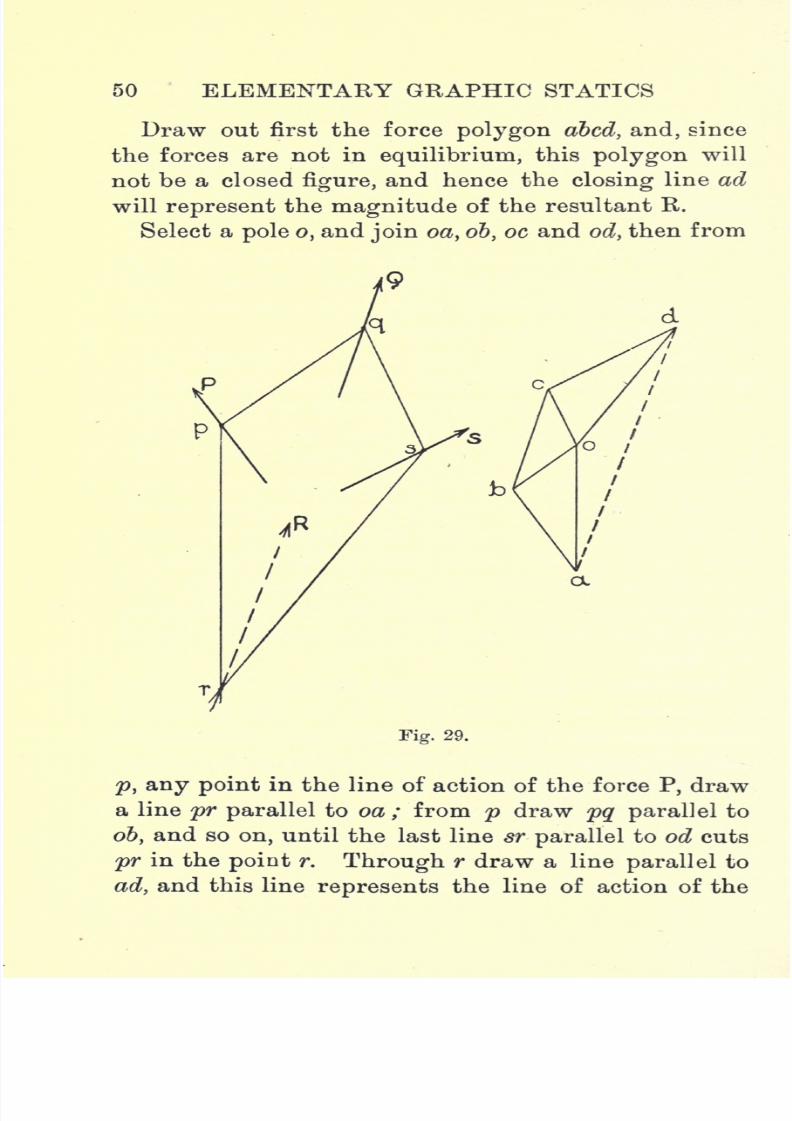
Three forces, P, Q and S, are acting as shown in
Fig. 29, and it is required to find their resultant in
magnitude and direction,
p
7/29/2019 Elementary Graphi 00wighrich
http://slidepdf.com/reader/full/elementary-graphi-00wighrich 66/256
50 ELEMENTARY GRAPHIC STATICS
Draw out first the force polygon abed, and, since
the forces are not in equilibrium, this polygon will
not be a closed figure, and hence the closing line ad
will represent the magnitude of the resultant R.
Select a pole o, and join oa, 6b, oc and od, then from
Fig. 29.
p, any point in the line of action of the force P, draw
a line pr parallel to oa ; from p draw pq parallel to
ob, and so on, until the last line sr parallel to od cuts
pr in the point r. Through r draw a line parallel to
ad, and this line represents the line of action of the

7/29/2019 Elementary Graphi 00wighrich
http://slidepdf.com/reader/full/elementary-graphi-00wighrich 67/256
NON-CONCURRENT FORCES 51
resultant, the sense, as indicated by the arrowhead,
being determined by following the forces round the
polygon, although, in this case, such a proceeding is
unnecessary, as the sense is obvious.
Resultant of Like Parallel Forces. A particular
case of the above is its application to the finding of
the resultant of a system of like parallel forces.
Set down the forces AB, BC, CD, DE and EF. (It
should be noted that the force polygon, in this
Fig. 30.
instance, is a straight line, and that the closing line
af represents the magnitude of the resultant.)
Select a pole o, and join oa, ob, oc, od, oe andof,
and
then from p, any point on the line of action of AB,
draw, in the space A, a line np parallel to oa ; from p
draw, in the space B, a line pq, parallel to 06, and so
on, until of is reached in the line uv, in the space F.
Produce np and vu to intersect in r, and through r
draw a line parallel to af.

7/29/2019 Elementary Graphi 00wighrich
http://slidepdf.com/reader/full/elementary-graphi-00wighrich 68/256
52 ELEMENTARY GRAPHIC STATICS
Then this line R represents the line of action of
the resultant, its magnitude being represented by of
the sum of the downward forces.
Resultant of Unlike Parallel Forces. The case
of unlike parallel forces will be easily understood
from an examination of Fig. 31 without much further
explanation. The only point calling for any par-
Fig. 31.
ticular care is the setting out of the forces in the
force polygon.
Thus, AB is set down as ab, but the next force BC
is measured upwards as be, the next two forces are
measured downwards as cd and de, while the last
force EF is measured upwards asef.
Note also that the point / is below the point a, so
that af, which represents the resultant, is measured
downwards, and consequently acts as shown at R.
No difficulty should be encountered in drawing in
the lines in their proper places if the rule adopted in
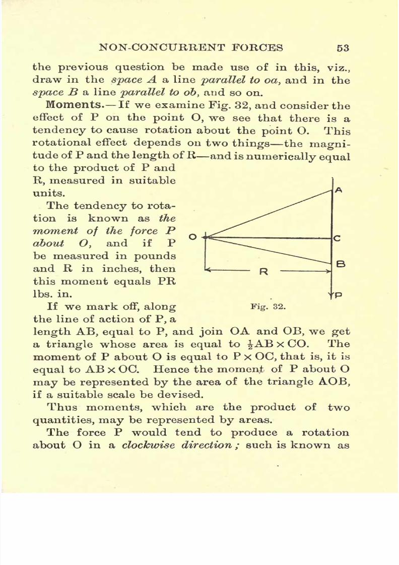
7/29/2019 Elementary Graphi 00wighrich
http://slidepdf.com/reader/full/elementary-graphi-00wighrich 69/256
NON-CONCURRENT FORCES 53
the previous question be made use of in this, viz.,
draw in the space A a line parallel to oa, and in the
space B a line parallel to ob, and so on.
Moments. If we examine Fig. 32, and consider the
effect of P on the point O, we see that there is a
tendency to cause rotation about the point 0. This
rotational effect depends on two things the magni-tude of P and the length ofR and is numerically equalto the product of P and
R, measured in suitable
units.
The tendency to rota-
tion is known as the
moment of the force Pabout 0, and if P
be measured in pounds
and R in inches, then
this moment equals PR
Ibs. in.
If we mark off, along
the line of action of P, a
length AB, equal to P, and join OA and OB, we get
a triangle whose area is equal to JAB x CO. The
moment of P about O is equal to P x OC, that is, it is
equal to AB x OC. Hence the moment of P about O
may be represented by the area of the triangle AOB,if a suitable scale be devised.
Thus moments, which are the product of two
quantities, may be represented by areas.
The force P would tend to produce a rotation
about in a clockwise direction ; such is known as
B
Fig. 32.

7/29/2019 Elementary Graphi 00wighrich
http://slidepdf.com/reader/full/elementary-graphi-00wighrich 70/256
54 ELEMENTARY GRAPHIC STATICS
a negative moment. A positive moment causes a
counterclockwise rotation.
Graphic Representation of Moments. The
moment of a force can also be represented graphi-
cally by the aid of the funicular polygon. (Fig. 33.)
Let AB be the given force and O the point about
which it is
tending
to cause rotation.
R
a
Wl ^>tQ
B
P
Fig. 33.
Draw ab parallel and equal to AB. Select a pole
o, and join oa and o&, the position of o being so
chosen that H is preferably an even number of
inches. From Q, any point in the line of action of
AB, draw two lines, QS and QT, parallel to oa and
ob respectively, and through O draw a line OD
parallelto AB, and cutting QS and QT in x and y
respectively. Draw QW perpendicular to OD.
7/29/2019 Elementary Graphi 00wighrich
http://slidepdf.com/reader/full/elementary-graphi-00wighrich 71/256
NON-CONCURRENT FORCES 55
Comparing triangles Q,xy and oab, we find they are
similar, and hence
ab : xy : : oc : WQ./. ab x WQ xyx oc.
=ABxWQ.Now AB x WQ equals the moment of P about O,
and therefore xyxoc also equals the moment of P
about O, and oc equals H, hence the moment of P
about Q=xyx H = intercept of first and last lines of
the funicular polygon on the line through the point
parallel to the force x polar distance.
The length xy must, of course, be measured to its
proper scale. Thus, if 1 m. = n Ibs. (force scale) and
1 in.=m ft. (space scale), then the moment of P=
xy x n x m x H Ibs. ft. about 0. (See page 79.)
We know from our study of statics that the
moment of the resultant of a system of forces is
equal to the algebraic sum of the moments of the
several forces about the same point, and that if a
system of forces has no tendency to rotate about
any point, then either the resultant is zero or, if
not, then it passes through the given point.
Although the construction just given is of no great
practical utility when dealing with a single force,
yet the application of the underlying principles to
the finding of the moment of the resultant of a
system is one of extremeutility.
In the treatment of such problems we are, in
general, reduced to two cases, in which we have to
deal firstly with non-parallel forces, and secondly
with parallel forces.

7/29/2019 Elementary Graphi 00wighrich
http://slidepdf.com/reader/full/elementary-graphi-00wighrich 72/256
56 ELEMENTARY GRAPHIC STATICS
Moment of a System of Non-parallel Forces. In
Fig. 34 we are given a system of non-parallel forces,
and we are required to find the moment of the system
about 0, or, what is the same thing, the moment of
the resultant about 0.
We have three distinct operations to perform in
solving this problem. First, we must find the magni-
Fig. 34.
tude of the resultant; second, we must find its line
of action;and third, we must find the moment of
the resultant about O.
Draw the force polygon abode, and join ae. The
length ae gives the magnitude of the resultant.
Select a pole o, and join oa, ob, oc, od and oe, the
pole o being so chosen that H is an even number of
inches. From p, draw pr parallel to oa, and pq
7/29/2019 Elementary Graphi 00wighrich
http://slidepdf.com/reader/full/elementary-graphi-00wighrich 73/256
NOK-CONCURRENT FORCES 57
parallel to ob ; fromq
drawqs parallel
to oc, and so
on, until the last line of the funicular polygon tr cuts
the first line pr in the point r.
Through r draw a line R parallel to ae, and this
line will represent the line of action of the resultant.
Through O draw a line OW parallel to R, and
cutting pr produced in y and //
produced
in x. Then
the moment of the resultant equals xy X H Ibs. in.
(xy being measured in pounds and H in inches). If
the system of forces be drawn to a scale of 1 in.
= n Ibs., then the moment of the resultant will
equal xy in. x n x H Ibs. in.
Moment of a System of Like Parallel Forces. It
will only be necessary to indicate the method of
solution in the case of like parallel forces.
Produce np to cut OW ina?,and produce ut in both
directions to cut OW in y and nx in r. Through r
draw a line parallel to ae. Then the moment of Rabout =Rx^ = #2/xH.
From a study of Fig. 35 it will be seen that it is
quite possible for the point to be in such a position
that the line through it parallel to ae would coincide
with the line of action of the resultant R, and that if
such be the case, then the resultant would have no
moment about that point.
Couples. A particular case of moments is the
one in which we are dealing with two equal and
unlike parallel forces. In Fig. 36 let the two
forces be P and P and the perpendicular dis-
tance between them be R. Adopting the same
treatment as in the previous problems, we begin

7/29/2019 Elementary Graphi 00wighrich
http://slidepdf.com/reader/full/elementary-graphi-00wighrich 74/256
58 ELEMENTARY GRAPHIC STATICS
by drawingthe force
polygonabc. Draw first ab
upwards to represent the upward force P, then be
downwards to represent the downward force P, and,
since the two forces are parallel and equal, obviously
the point c will coincide with a. Select a pole o, and
join ob and oa (which is also oc).From p draw a
w
Fig. 35.
line np parallel to oa ; from p draw a line pq parallel
to ob, and finally a line qs parallel to oc.
It will now be noticed that, since the point c coin-
cides with a, the force polygon is a closed figure, and
hence one condition of equilibrium is satisfied, but we
also notice that the lines np and qs, since they are
drawn parallel to the same line, are parallel to one
another, and would therefore never meet if produced.
Hence it follows that our funicular polygon would

7/29/2019 Elementary Graphi 00wighrich
http://slidepdf.com/reader/full/elementary-graphi-00wighrich 75/256
NON-CONCURRENT FORCES 59
not close, and consequently the system is not in
equilibrium.
If such a system be applied to a body, obviously
motion of some kind will take place, the resulting
motion being one of rotation without translation in
any direction.
Such a system is known as a couple, the distance
R being called the arm of the couple. Considering
Fig. 36.
its effect on the given body, we see that the total
moment is made up of two parts.
Total moment= (Pxr1) + (Pxr2).
=P(r1+r2).
= PxR.
.'. Total moment= the product of one force and the
arm of the couple.
This product is known as the moment of the
couple, while the direction of rotation is known as
the sense of the couple, and is positive or negative
according as the rotation is counterclockwise or
clockwise.
7/29/2019 Elementary Graphi 00wighrich
http://slidepdf.com/reader/full/elementary-graphi-00wighrich 76/256
60 ELEMENTARY GRAPHIC STATICS
The solution of
problems dealingwith
coupleswill
be readily obtained by the application of the methods
adopted in the solutions in the preceding examples.
The moment of a couple is the same about all points
in its plane.
A couple is measured by the magnitude of its
rotational
tendency,and two
couplesare
equalif
theyboth produce the same turning effect on a body, but
if we have two couples, whose rotational tendencies
are equal in magnitude but opposite in sense, the
total effect produced is zero, or, in other words, the
one couple neutralizes the other.
Hence,if we wish to balance or neutralize the
effect of a couple, we must apply to the system an
equivalent couple, that is a couple equal in moment
but opposite in sense.
Examples.
1. Draw a regular pentagon of 1 in. side. Letter
it clockwise
ABODE, beginningA at the
apex point.Bisect the sides and raise perpendiculars to repre-
sent forces. The forces have the following magni-
tudes : On AB, 13 Ibs.; on BO, 12 Ibs.;
on CD,
20 Ibs.;on DE, 18 Ibs.; and on EA, 14 Ibs. Deter-
mine the magnitude of the resultant, its direction and
theperpendicular
distance of its line of action from
the apex point.
2. Four forces, P, Q, S, T, act at the corners of a
square ABCD. The magnitudes of the forces are
P = 40 Ibs.; Q = 60 Ibs.
;S = 30 Ibs.
;T= 25 Ibs. The
lines of action of the forces are such that the angle
PAB= 120; A6Q = 150; B6s= 135; cf)T=120.
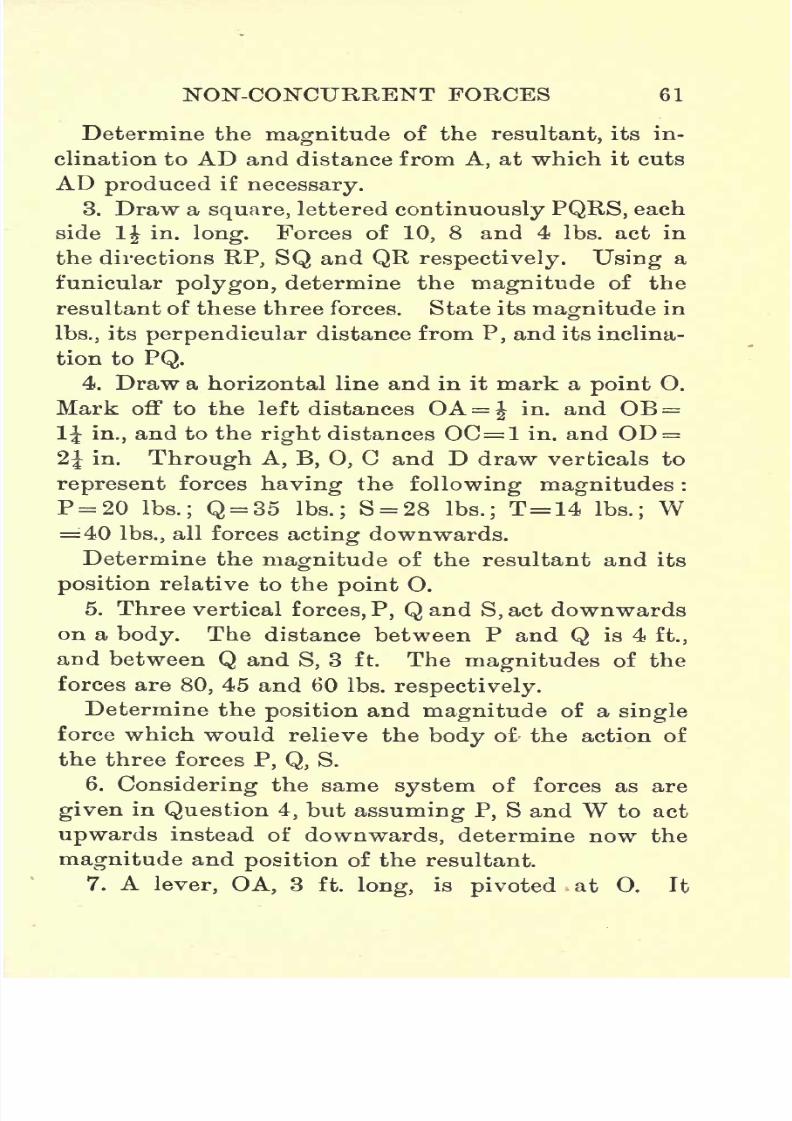
7/29/2019 Elementary Graphi 00wighrich
http://slidepdf.com/reader/full/elementary-graphi-00wighrich 77/256
NON-CONCURRENT FORCES 61
Determine the magnitude of the resultant, its in-
clination to AD and distance from A, at which it cuts
AD produced if necessary.
3. Draw a square, lettered continuously PQRS, each
side 1 in - long. Forces of 10, 8 and 4 Ibs. act in
the directions RP, SQ and QR respectively. Using a
funicular polygon, determine the magnitude of the
resultant of these three forces. State its magnitude in
Ibs., its perpendicular distance from P, and its inclina-
tion to PQ.
4. Draw a horizontal line and in it mark a point 0.
Mark off to the left distances OA= J in. and OB =
1J in., and to the right distances OC=1 in. and OD =
2J in. Through A, B, 0, C and D draw verticals to
represent forces having the following magnitudes :
P = 20 Ibs.; Q = 35 Ibs.; S = 28 Ibs.; T=14 Ibs.; W=40 Ibs., all forces acting downwards.
Determine the magnitude of the resultant and its
position relative to the point O.
5. Three vertical forces, P, Qand S,act downwards
on a body. The distance between P and Q is 4 ft.,
and between Q and S, 3 ft. The magnitudes of the
forces are 80, 45 and 60 Ibs. respectively.
Determine the position and magnitude of a single
force which would relieve the body of the action of
the three forces P, Q, S.
6. Considering the same system of forces as are
given in Question 4, but assuming P, S and W to act
upwards instead of downwards, determine now the
magnitude and position of the resultant.
7. A lever, OA, 3 ft. long, is pivoted at 0. It
7/29/2019 Elementary Graphi 00wighrich
http://slidepdf.com/reader/full/elementary-graphi-00wighrich 78/256
62 ELEMENTARY GRAPHIC STATICS
carries at its end A, rigidly attached to it, a circular
hoop 3 ft. diameter, the centre of the hoop coin-
ciding with A. Forces P, Q, T, S act tangentially to
the rini at the end of radii whose inclinations are 28,
108, 210 and 295 respectively. The magnitudes
of the forces are 80, 93, 74 and 34 Ibs. respectively.
Determine the moment of the system about O.
8. ABCD is a square of 3 in. side. Forces of 80,
90, 45 and 60 act outwards along the direction of the
diagonals at the points A, B, C and D respectively.
Determine the moment of the system about the
corner A of the square.
9. If in the previous question the forces had acted
outwards along the directions of the sides (all tending
to cause rotation of the square in the same direction),
what would then have been the moment of the
system about the centre of the square ?

7/29/2019 Elementary Graphi 00wighrich
http://slidepdf.com/reader/full/elementary-graphi-00wighrich 79/256
CHAPTER V
BENDING MOMENT AND SHEARING FORCE DIAGRAMS
IN the foregoing pages we have, with a few excep-
tions in Chapter III., dealt only with the general prin-
ciples involved in the solution of graphical problems,
and, as the utility of graphics is most exemplified in
its application to practical problems, we will now
proceed to consider the application of these principles
to the solution of simple problems involving the
stresses in the members of various composite
structures.
Before, however, passing on to the consideration of
roofs and bridges, we might, with advantage, take up,
at this point, the consideration of bending moment
and shearing force diagrams for beams of various
types and with various loadings.
Bending1 Moment. The bending moment at any
section of a beam is equal to the algebraic sum of the
moments of all forces acting either to right or left of
the section.
Possibly the best idea of what is taking place in a
beam section, subjected to a bending moment, can be
obtained from a study of the model shown diagram-
matically in Fig. 37. Here we have a cantilever,
from which a central section has been removed,
63
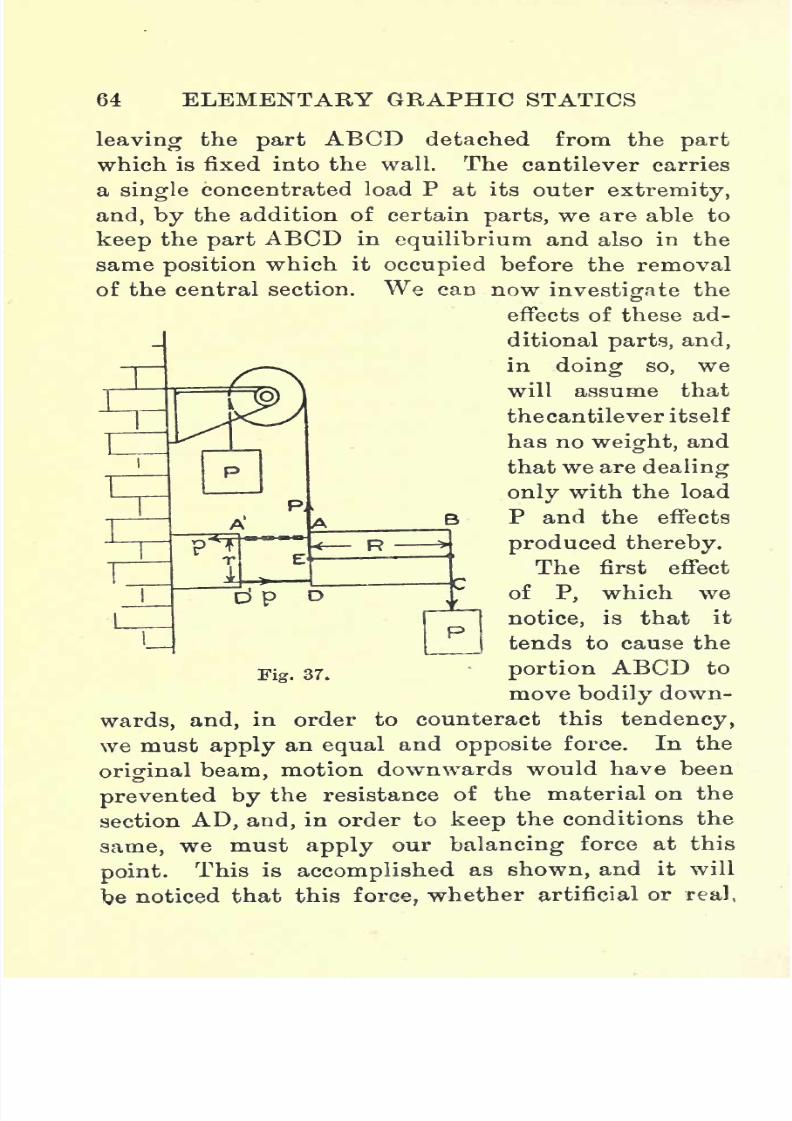
7/29/2019 Elementary Graphi 00wighrich
http://slidepdf.com/reader/full/elementary-graphi-00wighrich 80/256
64 ELEMENTARY GRAPHIC STATICS
leavingthe
partABCD detached from the
partwhich is fixed into the wall. The cantilever carries
a single concentrated load P at its outer extremity,
and, by the addition of certain parts, we are able to
keep the part ABCD in equilibrium and also in the
same position which it occupied before the removal
of the central section. We can nowinvestigate
the
effects of these ad-
ditional parts, and,
in doing so, we
will assume that
thecantilever itself
has noweight,
and
that we are dealing
only with the load
P and the effects
produced thereby.
The first effect
ofP,
which we
notice, is that it
tends to cause the
Fig 37> portion ABCD to
move bodily down-
wards, and, in order to counteract this tendency,
we mustapply
anequal
andopposite
force. In the
original beam, motion downwards would have been
prevented by the resistance of the material on the
section AD, and, in order to keep the conditions the
same, we must apply our balancing force at this
point.This is accomplished as shown, and it will
benoticed that this
force,
whether artificial or real,

7/29/2019 Elementary Graphi 00wighrich
http://slidepdf.com/reader/full/elementary-graphi-00wighrich 81/256
BENDING MOMENT 65
togetherwith the load P, forms a
couple
whose
moment is P x R, and whose rotational tendency is
clockwise.
This couple constitutes the bending moment on the
section AD.
We have now this rotational tendency to deal with,
and we have seen that this
tendency
can be neutral-
ized only by a couple of equal and opposite tendency.
Suppose, now, that ABCD starts to rotate about E,
one of the effects produced is a lessening of the
distance DD1 and the other an increasing of the
distance AA1
,and these two effects are neutralized
in the model
byintroducing, at DD 1
,a strut, and at
AA1 a tie in the nature of a chain. The force acting
in the chain is a pull or tension, that in the strut a
push or compression. These two forces acting at a
distance r from one another form a couple whose
moment is p x r equal to P X R, but whose rotational
tendency is counterclockwise. These two couples
form a system in equilibrium. In the original beam,
the push and pull, constituting the couple pxr, are
represented by the tensile and compressive stresses
induced in the fibres of the material, while the up-
ward force which we applied at AD is represented bythe shearing resistance on AD. The effect of apply-
ing a force P is therefore twofold, for on any section
AD we ha-ve induced a bending moment P X R, which
is neutralized by the resisting moment pr, and also
a shearing force, which is neutralized by the shearing
resistance.
Shearing* Force- The shearing force on any section
E

7/29/2019 Elementary Graphi 00wighrich
http://slidepdf.com/reader/full/elementary-graphi-00wighrich 82/256
66 ELEMENTARY GRAPHIC STATICS
of a beam is
equalto the
algebraic
sumof
all
forcesacting either to right or left of the section.
Conventions in Use regarding- B.M. and S.F.
We have just seen that, in the case above, the stress
in the top layers of the cantilever was of the nature
of a pull, and obviously, if the material be extensible,
then those
top layerswould increase in
length, while,for the opposite reason, the bottom layers would
decrease in length, and the final shape of the canti-
lever would be as shown in Fig. 38 (a), the curve being
convex upwards; in
this case the bend-
ingmoment is said
^ to be positive and
the diagram of
2 <j f bending moment
^ * I is drawn above
^ ^uthe datum line.
p- 38
Should the beam,
however, take up
the shape shown in Fig. 38 (6), that is, concave
upwards, the bending moment is said to be nega-
tive, and the diagram is then drawn below the
datum line.
Withregard
to the
shearingforce, if
anysection
of the beam tends to move upwards relative to an
adjacent section to the right, as shown in Fig. 38 (c),
the shearing force is said to be positive,and the
diagram is drawn above the datum line, while, if
the section tends to move down relative to its right-
handneighbour,
as in
Fig.
38(d),
the shearing force
7/29/2019 Elementary Graphi 00wighrich
http://slidepdf.com/reader/full/elementary-graphi-00wighrich 83/256
BENDING MOMENT 67
is said to benegative,
and the
diagramis drawn
below the datum line.
Construction of a Parabola. In dealing with
bending-moment diagrams the curve known as the
parabola appears so often that it might be well, at
this stage, to indicate two approximate methods of
setting
out the curve.
First Method. Let AB, in Fig. 39, be the line on
which the parabola is to be described. Bisect AB in
E and draw EC perpendicular to AB and of such a
length that EC represents the required depth of the
parabola. Produce EC to D, making CD = EC. Join
AD and BD and divide AB and DB into
any
number
of equal parts, numbering them as shown, then join
across the corresponding numbers. Trace in the
required curve tangential to the cross lines.
Second Method. As before, let AB be the given
line, on which the parabola is to be described. Bisect
AB in D and draw DC perpendicular to AB and
equal to the required depth of the parabola. Com-
plete the rectangle AEFB, divide EC and AE into
the same number of equal parts, numbering them as
indicated. Join the division points 1, 2, 3, 4 in the
line AE to the point C. From the points 1, 2, 3, 4
in EC raise perpendiculars to cut the Jines from the
correspondingly numbered points in AE as shown
Through the intersections so obtained trace the
required curve.
Note that the accuracy of either method depends
on the number of subdivisions : the greater tho
number the greater the accuracy.
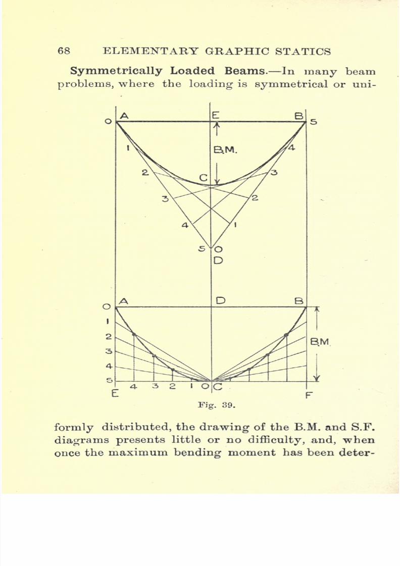
7/29/2019 Elementary Graphi 00wighrich
http://slidepdf.com/reader/full/elementary-graphi-00wighrich 84/256
68 ELEMENTARY GRAPHIC STATICS
SymmetricallyLoaded Beams. In
many beamproblems, where the loading is symmetrical or uni-
BM
Fig. 39.
formly distributed, the drawing of the B.M. and S.F.
diagrams presents little or no difficulty, and, when
oncethe maximum
bendingmoment has been deter-
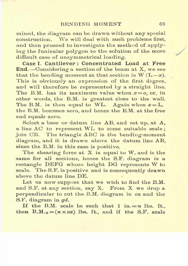
7/29/2019 Elementary Graphi 00wighrich
http://slidepdf.com/reader/full/elementary-graphi-00wighrich 85/256
BENDING MOMENT 69
mined,the
diagramcan be drawn without
any specialconstruction. We will deal with such problems first,
and then proceed to investigate the method of apply-
ing the funicular polygon to the solution of the more
difficult case of unsymmetrical loading.
Case I. Cantilever : Concentrated Load at Free
End.Considering
a section of the beam atX,
we see
that the bending moment at that section is W (L x).
This is obviously an expression of the first degree,
and will therefore be represented by a straight line.
The B.M. has its maximum value when x o, or, in
other words, the B.M. is greatest close to the wall.
The B.M. is thenequal
to WL.Again
when x=L,
the B.M. becomes zero, and hence the B.M. at the free
end equals zero.
Select a base or datum line AB, and set up, at A,
a line AC to represent WL to some suitable scale;
join CB. The triangle ABC is the bending-moment
diagram,and it is drawn above the datum line
AB,since the B.M. in this case is positive.
The shearing force at X is equal to W, and is the
same for all sections, hence the S.F. diagram is a
rectangle DEFG whose height DG represents W to
scale. The S.F. is positive and is consequently drawn
above the datum line DE.
Let us now suppose that we wish to find the B.M.
and S.F. at any section, say X. From X we drop a
perpendicular to cut the B.M. diagram in ca and the
S.F. diagram in gd.
If the B.M. scale be such that 1 in.=7& Ibs. ft.,
then B.M.x=
Oxca)Ibs. ft., and if the S.F. scale
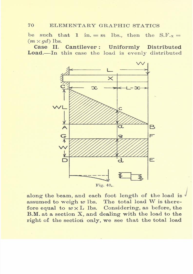
7/29/2019 Elementary Graphi 00wighrich
http://slidepdf.com/reader/full/elementary-graphi-00wighrich 86/256
70 ELEMENTARY GRAPHIC STATICS
be such that 1 in. = m Ibs., then the S.F.X =(m x gd) Ibs.
Case II. Cantilever: Uniformly Distributed
Load. In this case the load is evenly distributed
W
Fig. 40.
along the beam, and each foot length of the load is
assumed to weigh w Ibs. The total load W is there-
fore equal to w x L Ibs. Considering, as before, the
B.M. at a section X, and dealing with the load to the
right of the section only, we see that the total load
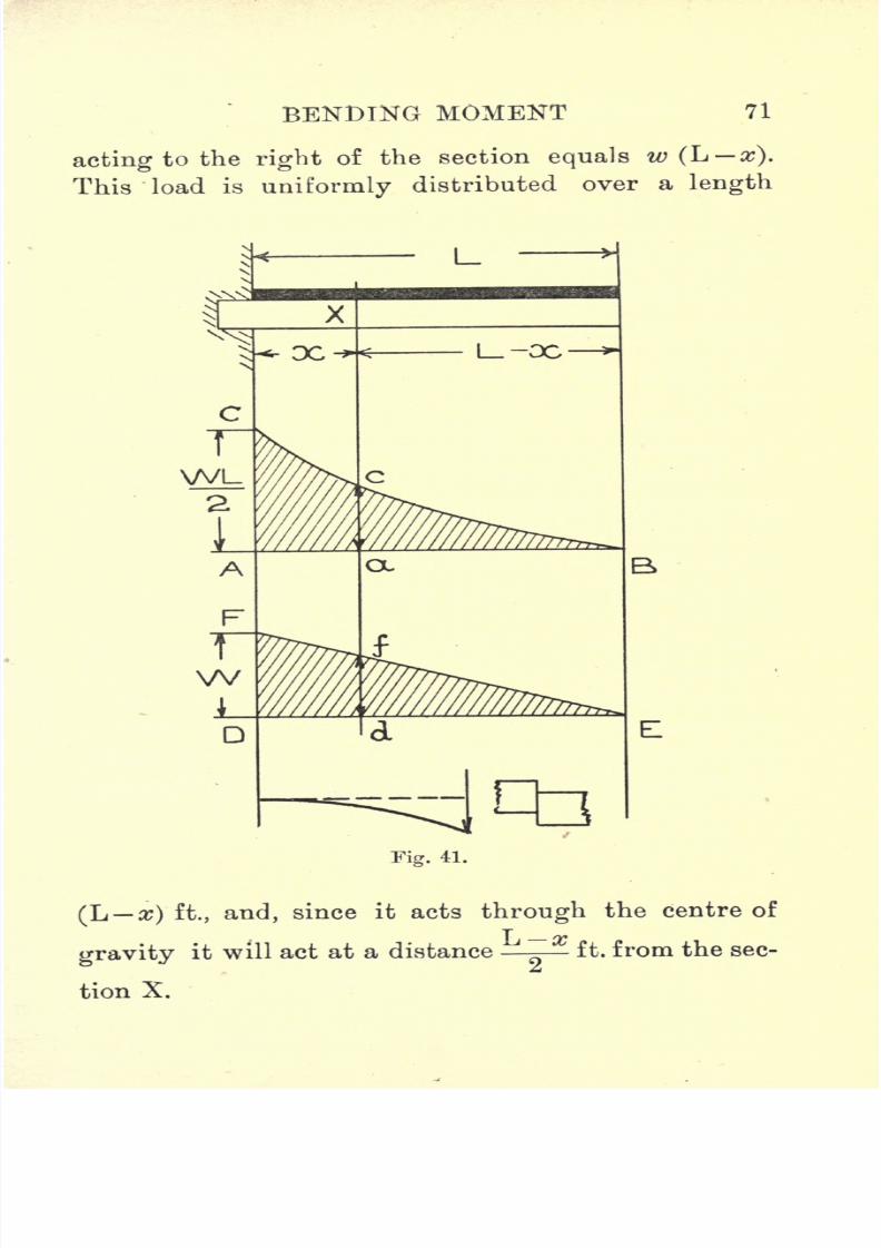
7/29/2019 Elementary Graphi 00wighrich
http://slidepdf.com/reader/full/elementary-graphi-00wighrich 87/256
BENDING MOMENT 71
acting to the rightof the section
equalsw
(L x).
This load is uniformly distributed over a length
Fig. 41.
(L a;) ft., and, since it acts through the centre of
gravity it will act at a distance - ft. from the sec-
tion X.
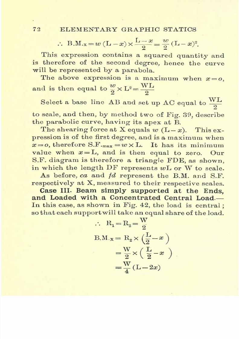
7/29/2019 Elementary Graphi 00wighrich
http://slidepdf.com/reader/full/elementary-graphi-00wighrich 88/256
72 ELEMENTARY GRAPHIC STATICS
This expression contains a squared quantity and
is therefore of the second degree, hence the curve
will be represented by a parabola.
The above expression is a maximum when x = o,
andis then
equalto
x L
2
Select a base line AB and set up AC equal to
to scale, and then, by method two ofFig. 39, describe
the parabolic curve, having its apex at B.
The shearing force at X equals w (L-
x). This ex-
pression is of the first degree, and is a maximum whenx= o, therefore S.F.max =wxL. It has its minimum
value when #= L, and is then equal to zero. Our
S.F. diagram is therefore a triangle FDE, as shown,
in which the length DF represents wL or W to scale.
As before, ca and fd represent the B.M. and S.F.
respectively at X, measured to their respective scales.
Case III. Beam simply supported at the Ends,
and Loaded with a Concentrated Central Load.
In this case, as shown in Fig. 42, the load is central;
so that each support will take an equal share of the load.
R =R =Wi 2
2
B.M.x=R2 x(J-*)

7/29/2019 Elementary Graphi 00wighrich
http://slidepdf.com/reader/full/elementary-graphi-00wighrich 89/256
BENDING MOMENT n
Thisexpression
is
represented byastraight
line,
the maximum value occurring when x = o, i.e., at the
centre, while the minimum value occurs at the ends
when#=-, the value then being zero. The maxi-2t
mum value = . The B.M. diagram, in this case, is'
atriangle, having its apex at the centre of the span ;
it is drawn below the datum Hue, since the B.M. in this
instance is negative. The maximum depth of the
,. . WL,diagram equals to some scale.
The S.F. at any section in the left-hand half is
obviously R:or
,and is constant in this half of the
2i
beam. Hence our S.F. diagram, for this half, is a
rectangle of height (to scale), and is drawn above
the datum line, since the S.F. in this half is positive.
Passing on from left to right, we find that, as soon
as we pass over the centre, the value of the S.F. alters,
for now we have two loads to deal with, and, in
estimating our S.F., we must take their algebraic sum.
We have acting upwards andW acting downwards,
so that the S.F. is equal to +^- W= - ^.2
This value is constant from the centre to the
right-hand support, and is therefore represented by a
rectangle of depth ,but this time drawn below the
2i
datum line.
j
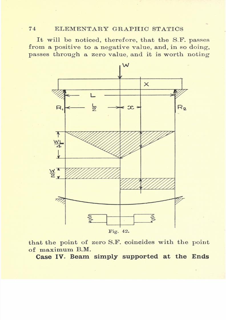
7/29/2019 Elementary Graphi 00wighrich
http://slidepdf.com/reader/full/elementary-graphi-00wighrich 90/256
74 ELEMENTARY GRAPHIC STATICS
It will benoticed, therefore,
that the S.F.passes
from a positive to a negative value, and, in so doing,
passes through a zero value, and it is worth noting
W
R,
t
WL
w*2 JL
X
Fig. 42.
that the point of zero S.F. coincides with the point
of maximum B.M.
Case IV. Beam simply supported at the Ends
7/29/2019 Elementary Graphi 00wighrich
http://slidepdf.com/reader/full/elementary-graphi-00wighrich 91/256
BENDING MOMENT 75
Carrying-aUniformly
Distributed Load. The load
in this case, as shown in Fig. 43, is uniformly dis-
tributed across the span, and, as in the previous case,
the reactions, Rxand R
2 ,are each equal to half the
total load. The load per foot-run may be taken as
w lb., hence the total load is equal to w x L Ibs.
Each reaction is therefore equal to -, or-
,
where
W-^xL.
Considering the B.M. at any section X distant
x from the centre-line, we find that we have two
loads acting to the right of the section, viz., an
upwardload R
2
=acting
counterclockwise at
distance(
-- x\ from X, and a downward load
consisting of a piece of the total load of length
- _ x\ whose weight is w (--x\ acting clockwise
at a distance - ( -x\ from X.
7/29/2019 Elementary Graphi 00wighrich
http://slidepdf.com/reader/full/elementary-graphi-00wighrich 92/256
V6 ELEMENTARY GRAPHIC STATICS
It
appearsfrom this
expressionthat the B.M. dia-
gram is a parabola. The expression becomes zero
when x =- + -, hence at the supports the B.M. is zero.
The expression has its maximum value when a; = 0, i.e.,
at the centre, the value then being or
The drawing of the B.M. diagram should now present
no difficulty.
The S.F. at X is equal to the algebraic sum of the
two forces acting to the left (or right) of the section.
C1 T7S.F.X=
The S.F. is therefore represented by a straight line,
and when#= o, the S.F.=o, this value occurring at
the centre. The maximum values occur when
x i;p the values then being ,and occurring at
'2 2
the supports. The construction of the diagram will
be readily understood from the adjoining figure.
The solutions of the four typical' cases which we
have been considering hardly merit the term
"graphical solutions," since the calculation of the
maximum and minimum valuesof
theB.M.
andS.F. was performed before setting out the diagrams,
still the constructions adopted are quite justifiable
in view of the symmetry of the loadings. Examples
so nicely arranged are the exception rather than the
rule in practice, the arrangement and loadings in
practicalcases
being moreor less
unsyuimetrical.

7/29/2019 Elementary Graphi 00wighrich
http://slidepdf.com/reader/full/elementary-graphi-00wighrich 93/256
BENDING MOMENT 77
We will nowproceed
to
investigate
one or two cases of
unsymmetrical loading, making use of the funicular
polygon in constructing the B.M. diagram.
Fig. 43.
Unsymmetrieally Loaded Beams. Let us consider
first the case of a simple cantilever loaded with a
series of concentrated loads AB, BC, CD, and DE.
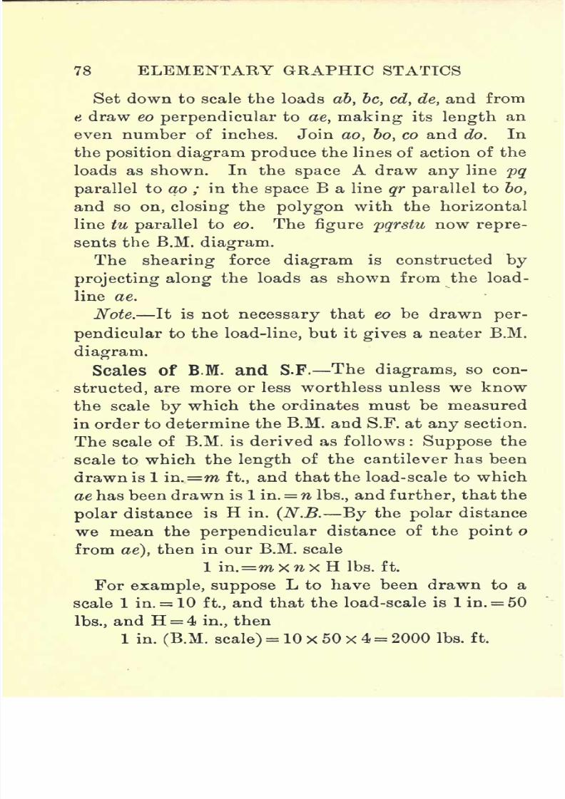
7/29/2019 Elementary Graphi 00wighrich
http://slidepdf.com/reader/full/elementary-graphi-00wighrich 94/256
78 ELEMENTARY GRAPHIC STATICS
Set down to scale the loads ab, be, cd, de, and from
t draw eo perpendicular to ae, making its length an
even number of inches. Join ao, bo, co and do. In
the position diagram produce the lines of action of the
loads as shown. In the space A draw any line pq
parallel to ao ; in the space B a line qr parallel to bo,
and so on,closing
the
polygonwith the horizontal
line tu parallel to eo. The figure pqrstu now repre-
sents the B.M. diagram.
The shearing force diagram is constructed by
projecting along the loads as shown from the load-
line ae.
Note. It is notnecessary
that eo be drawnper-
pendicular to the load-line, but it gives a neater B.M.
diagram.
Scales of B.M. and S.F. The diagrams, so con-
structed, are more or less worthless unless we know
the scale by which the ordinates must be measured
in order to determine the B.M. and S.F. at
anysection.
The scale of B.M. is derived as follows : Suppose the
scale to which the length of the cantilever has been
drawn is 1 in.=m ft., and that the load-scale to which
ae has been drawn is 1 in. = n Ibs., and further, that the
polar distance is H in. (N.B. By the polar distance
wemean the
perpendiculardistance of the
pointo
from ae), then in our B.M. scale
1 in.=m X n X H Ibs. ft.
For example, suppose L to have been drawn to a
scale 1 in. = 10 ft., and that the load-scale is 1 in. = 50
Ibs., and H = 4 in., then
1 in.
(B.M. scale)
= 10x50x4 = 2000 Ibs. ft.

7/29/2019 Elementary Graphi 00wighrich
http://slidepdf.com/reader/full/elementary-graphi-00wighrich 95/256
BENDING MOMENT 79
To find the B.M. at X we drop a perpendicular and
measure the intercept between rs and tu ; then, say
this measures 1*3 in., the B.M.x is consequently equal
to 1-3x2000 = 2600 Ibs. ft.
To show that this diagram really represents the
B.M. diagram, we might consider it a little more fully,
Fig. 44.
especially as the principle underlying this case is
applicable in all others. We saw, in Chapter IV.,
that the moment of a system of forces about a point
was equal to the intercept of the first and last lines
of the funicular polygon on a line through the point
parallel to the resultant force, multiplied by the polar
distance.
Considering now the section close to the wall, we

7/29/2019 Elementary Graphi 00wighrich
http://slidepdf.com/reader/full/elementary-graphi-00wighrich 96/256
80 ELEMENTARY GRAPHIC STATICS
have,at that section, a line
xy parallelto the resultant
of the loads. The first line of the funicular polygon
is pq, and the last is tu, hence the intercept is the line
pu. The moment of the system about this section is
therefore pu X H, pu representing a force and H a
distance.
It will be obvious that if Lhad beendoubled,
other
things remaining as before, then the length pu would
also have been doubled, so that if L be reduced to
some definite scale, then the true length of pu will
have been reduced in the same ratio. Hence, if
1 in. m ft., it follows that our diagram is reduced
12mtimes,
and,therefore,
the full-size
lengthof
puwould be (pu x 12m) ins. Again, each inch represents
n Ibs., and consequently the magnitude of the force
represented by pu is (pu x 12m X n) Ibs. The moment
of this force about the section is therefore pux 12mTT
XtixH Ibs. ins., or puxlZmxnx Ibs. ft., which
is equal to pu X m X n x H Ibs. ft.
This may be written as
The depth of the B.M. diagram under the section x
the B.M. scale.
Note carefully that, although the result is expressed
as Ibs. ft., the distance H is measured in inches and
not in feet. Confusion often arises over this point,
but a careful study of the above reasoning will over-
come any difficulty which may arise.
Simply supported Beam with Concentrated
Loads. Let us consider now the case as shown in
Fig.45, in which we have a simply
supported
beam

7/29/2019 Elementary Graphi 00wighrich
http://slidepdf.com/reader/full/elementary-graphi-00wighrich 97/256
BENDING MOMENT 81
carrying concentrated loads AB, BC and CD. Pro-duce the lines of action of the forces and set down
the lines ab, be and cd to represent the loads. Select
a pole o, so that H is an even number of inches. (In
the majority of cases the best position for o is that
which makes aod approximately an equilateral
triangle.)Join
ao, bo,co and do.
From p any pointin the line of action of Rj draw, in the space A, a
line pq parallel to oa ; from q draw, in the space B, a
line qr parallel to ob, and so on until the point t is
reached. Join pt, then the closed figure pqrst is the
bending-moment diagram for the above beam.
From o draw oeparallel
topt,
and the lines de and
ea represent the reactions R2and R
x respectively.
The shearing force diagram is constructed by
projecting across from the load-line as indicated.
Considering the S.F. in the left-hand half of the beam,
we find that the S.F. from Rxto AB is constant and
equalto R
x,
beingalso
positive,so that it can be
represented by a rectangle whose height is Rxor ea
on the load-line. Passing now to the right, the S.F.
between AB and BC is represented by the sum
of Rx acting upwards and AB acting downwards, or
on the load-line by a force ea acting upwards and ab
acting
downwards. The nett S.F. between AB and
BC is therefore eb acting upwards, and hence our S.F.
diagram for this part is a rectangle of height eb.
The remainder of the diagram requires no further
explanation.
Overhung: Beam with Concentrated Loads.
The following
example
is well worth careful con-
F
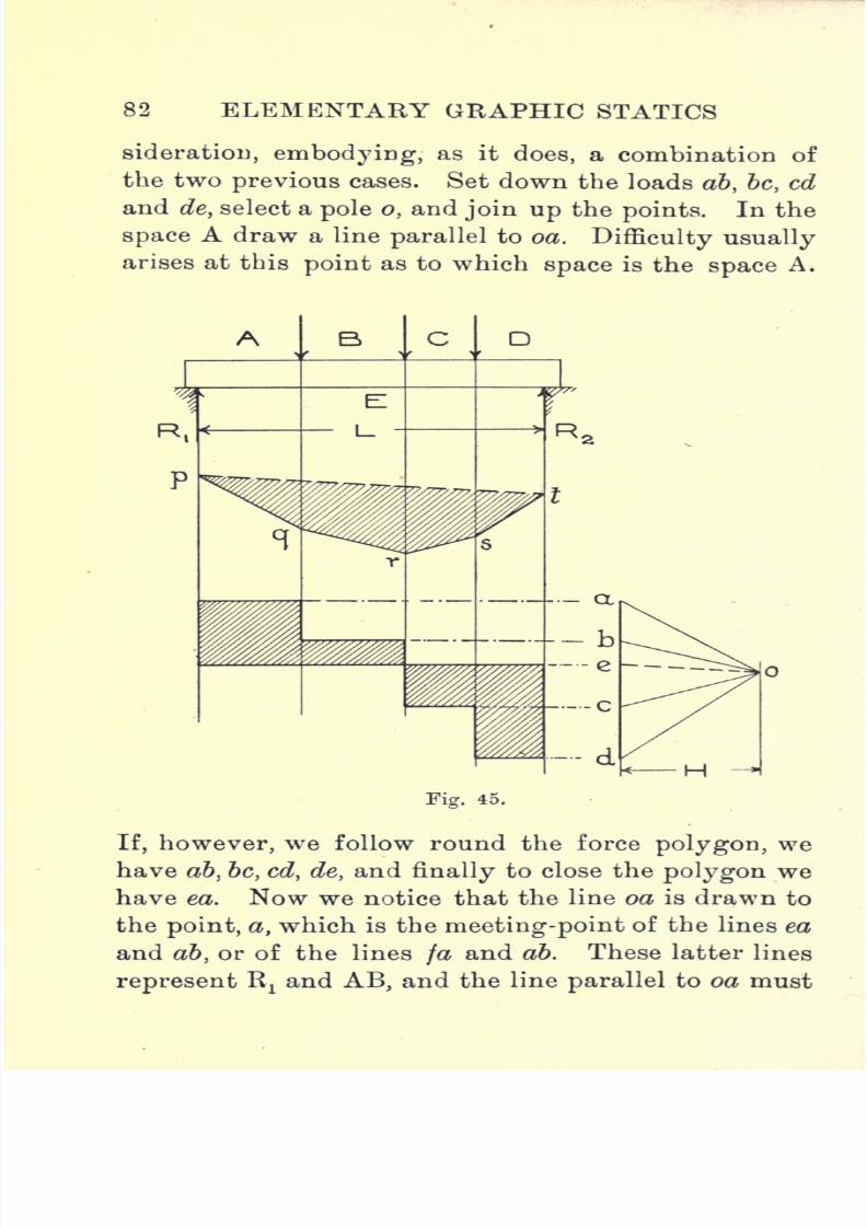
7/29/2019 Elementary Graphi 00wighrich
http://slidepdf.com/reader/full/elementary-graphi-00wighrich 98/256
82 ELEMENTARY GRAPHIC STATICS
sideratiou, embodying,as it
does,a combination of
the two previous cases. Set down the loads ab, be, cd
and de, select a pole o, and join up the points. In the
space A draw a line parallel to oa. Difficulty usually
arises at this point as to which space is the space A.
Fig. 45.
If, however, we follow round the force polygon, we
have ab, be, cd, de, and finally to close the polygon we
have ea. Now we notice that the line oa is drawn to
the point, a, which is the meeting-point of the lines ea
and ab, or of the lines fa and ab. These latter lines
representR
:
andAB,
and the line
parallelto oa must

7/29/2019 Elementary Graphi 00wighrich
http://slidepdf.com/reader/full/elementary-graphi-00wighrich 99/256
BENDING MOMENT 83
connect Kt
and AB in theposition diagram.
The
line pq parallel to oa is the line required. The drawing
of the other lines should now present no difficulty.
It will be noticed in this case that we have a
crossed diagram. The points x, x, denoting zero
B.M., are called points of inflection, and indicate a
Fig. 46.
change of curvature in the beam at these points.
In constructing the S.F. diagram it is worth noting
that the points of inflection are coincident with
sections in which the S.F. is a maximum.
Simply supported Beam: Compound Loading-.
The following case, as shown in Fig. 47, indicates the
method to be adopted when constructing the B.M.
diagram for a beam with compound loading.
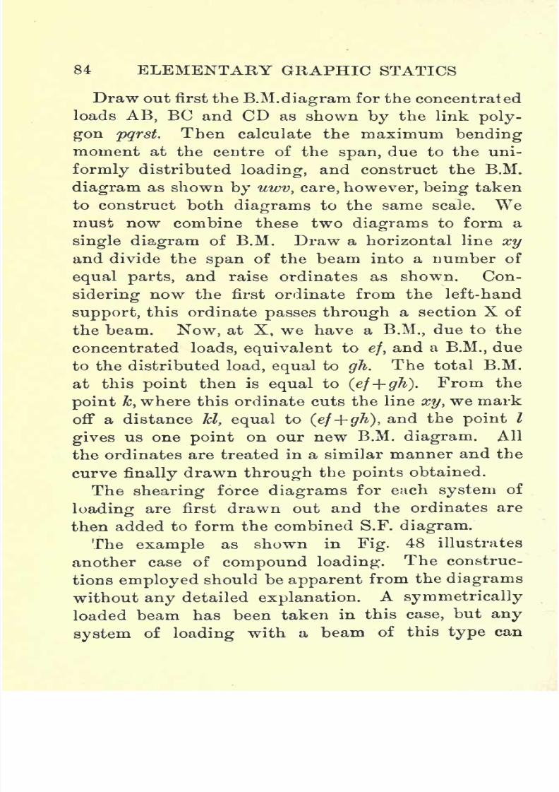
7/29/2019 Elementary Graphi 00wighrich
http://slidepdf.com/reader/full/elementary-graphi-00wighrich 100/256
84 ELEMENTARY GRAPHIC STATICS
Draw out first the B.M.
diagramfor the concentrated
loads AB, BC and CD as shown by the link poly-
gon pqrst. Then calculate the maximum bending
moment at the centre of the span, due to the uni-
formly distributed loading, and construct the B.M.
diagram as shown by uwv, care, however, being taken
to construct bothdiagrams
to the same scale. Wemust now combine these two diagrams to form a
single diagram of B.M. Draw a horizontal line xy
and divide the span of the beam into a number of
equal parts, and raise ordinates as shown. Con-
sidering now the first ordinate from the left-hand
support,this ordinate
passes througha section X of
the beam. Now, at X, we have a B.M., due to the
concentrated loads, equivalent to ef,and a B.M., due
to the distributed load, equal to gh. The total B.M.
at this point then is equal to (ef+ gh). From the
point k, where this ordinate cuts the line xy, we mark
off a distance kl,
equalto
(ef+gh),and the
pointI
gives us one point on our new B.M. diagram. All
the ordinates are treated in a similar manner and the
curve finally drawn through the points obtained.
The shearing force diagrams for euch system of
loading are first drawn out and the ordinates are
then added to form the combined S.F.
diagram.The example as shown in Fig. 48 illustrates
another case of compound loading. The construc-
tions employed should be apparent from the diagrams
without any detailed explanation. A symmetrically
loaded beam has been taken in this case, but any
systemof
loadingwith a beam of this
type
can
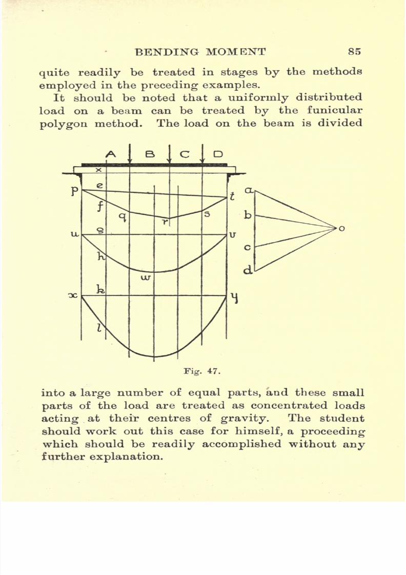
7/29/2019 Elementary Graphi 00wighrich
http://slidepdf.com/reader/full/elementary-graphi-00wighrich 101/256
BENDING MOMENT 85
quite readilybe treated in
stages bythe methods
employed in the preceding examples.
It should be noted that a uniformly distributed
load on a beam can be treated by the funicular
polygon method. The load on the beam is divided
k
a
Fig. 47.
into a large number of equal parts, and these small
parts of the load are treated as concentrated loads
acting at their centres of gravity. The student
should work out this case for himself, a proceeding
which should be readily accomplished without anyfurther explanation.
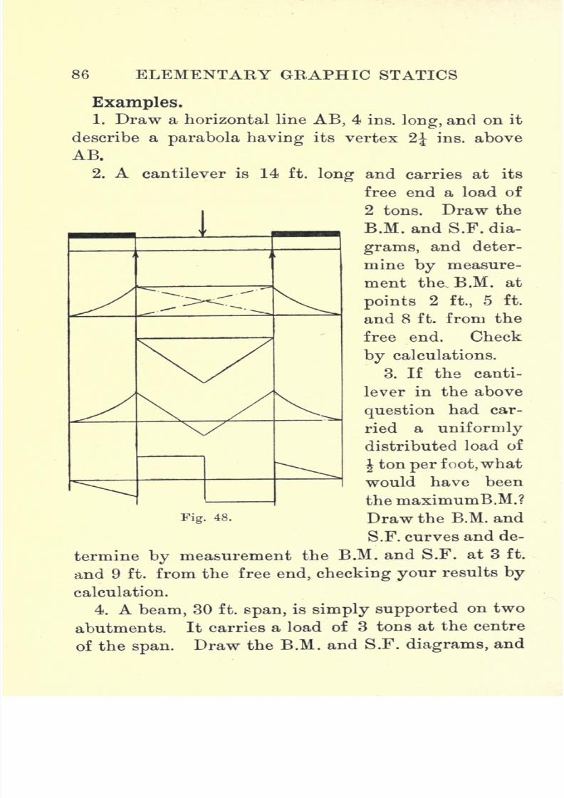
7/29/2019 Elementary Graphi 00wighrich
http://slidepdf.com/reader/full/elementary-graphi-00wighrich 102/256
86 ELEMENTARY GRAPHIC STATICS
Examples.1. Draw a horizontal line AB, 4 ins. long, and on it
describe a parabola having its vertex 2J ins. above
AB.
2. A cantilever is 14 ft. long and carries at its
free end a load of
2 tons. Draw theB.M. and S.F. dia-
grams, and deter-
mine by measure-
ment the, B.M. at
points 2 ft., 5 ft.
and 8 ft. from thefree end. Check
by calculations.
3. If the canti-
lever in the above
question had car-
ried a uniformlydistributed load of
J ton per foot,what
would have been
the maximumB.M.?
Fig. 48. Draw the B.M. and
S.F. curves and de-
termine by measurement the B.M. and S.F. at 3 ft.
and 9 ft. from the free end, checking your results by
calculation.
4. A beam, 30 ft. span, is simply supported on two
abutments. It carries a load of 3 tons at the centre
of the span. Draw the B.M. and S.F. diagrams, and
7/29/2019 Elementary Graphi 00wighrich
http://slidepdf.com/reader/full/elementary-graphi-00wighrich 103/256
BENDING MOMENT 87
determine the value of the B.M. and S.F. 6 ft. fromthe left-hand support.
5. Assuming the above beam to carry a uniformly
distributed load of 600 Ibs. per foot-run, what would
be the maximum B.M. ? Draw the curves of B.M. and
S.F. and determine the values at a section 8 ft. from
the right-hand support.6. A beam, 20 ft. long, projects from a wall. This
beam carries a platform which rests on battens placed
at intervals of 4 ft., the first being placed on the free
end of the beam. Starting from the free end, the
loads coming on the battens are 400, 600, 700, 900,
and 500Ibs.
respectively. Draw the curvesof B.M.
and S.F. and determine the B.M. and S.F. 6 ft. and 10
ft. from the free end. What is the maximum B.M. ?
7. A beam, 40 ft. span, rests on two abutments.
Cross joists are fixed to this beam at points 4, 17, 24,
and 32 ft. from the left-hand support, the correspond-
ingloads
being 2, 3,2'5
and4 tons
respectively.Draw
the diagrams of B.M. and S.F., and determine the
values of the B.M. and S.F. at the centre of the beam,
also at points 10 and 26 ft. from the left-hand abutment.
8. A beam, 40 ft. long, rests on two columns 28 ft.
apart. On the left-hand end the overhang is 7 ft.,
and on theright-hand
end 5 ft. A load of 4 tons
rests on the left-hand overhang, and 3 tons on the
right hand, both at the extreme ends. Two loads of 2
tons each are placed on the centre span, one 8 ft. from
the left-hand support and the other 10 ft. from the right
hand. Draw the B.M. and S.F. diagrams and determine
the B.M. and S.F. at the centre of
length
of the beam.

7/29/2019 Elementary Graphi 00wighrich
http://slidepdf.com/reader/full/elementary-graphi-00wighrich 104/256
88 ELEMENTARY GRAPHIC STATICS
9.
A beam, weighing 40 Ibs. per foot, covers a spanof 36 ft. It carries a uniformly distributed load of
200 Ibs. per foot-run, in addition to 3 loads, each
weighing 1 ton, placed at 8, 14 and 28 ft. from the
left-hand support. Draw the B.M. and S.F. diagrams.
What is the maximum B.M., and where does it occur ?
Whatis
the B.M. and S.F. 10 ft. from the right-handsupport ?
10. Assuming the beam in Question 8 to carry
a uniformly distributed load of 150 Ibs. per foot-
run, in addition to the dead loads given, determine
graphically the B.M. and S.F. at the centre of length
of the beam.What
is the
maximum B.M. and S.F.,and where does it occur ?
7/29/2019 Elementary Graphi 00wighrich
http://slidepdf.com/reader/full/elementary-graphi-00wighrich 105/256
CHAPTER VI
BEAMS WITH ROLLING LOADS
IN all the cases which we have considered so
far, we have seen that the loads were either con-
centrated at fixed points or uniformly distributed
along the length of the beam. Such loads are
known as dead loads. In manycases in
practice,
however, more especially in bridges, crane girders,
and such structures, the loads, instead of being
fixed in position, are free to move along the
beam. Such loads are known as rolling, or live
loads.
Single Concentrated Rolling
1
Load. Wewill
nowexamine a few cases of rolling loads, considering first
the case of a single concentrated load rolling along
the simply supported beam, assuming the load to
roll from Rxto R
2 ,as shown in Fig. 49. Considering
the B.M. at a section X distant x from the left-hand
support,we have
The maximum B.M., with a concentrated dead load,
alwaysoccurs
just
under the load, so that for the
89
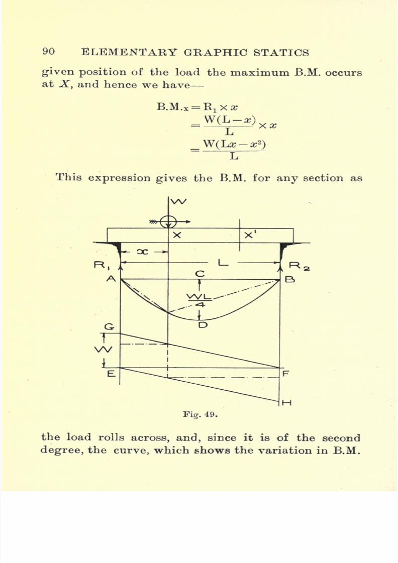
7/29/2019 Elementary Graphi 00wighrich
http://slidepdf.com/reader/full/elementary-graphi-00wighrich 106/256
90 ELEMENTARY GRAPHIC STATICS
given position of the load the maximum B.M. occursat X, and hence we have
This expression gives the B.M. for any section as
w
H
Fig. 49.
the load rolls across, and, since it is of the second
degree,the
curve,which shows the variation in
B.M.
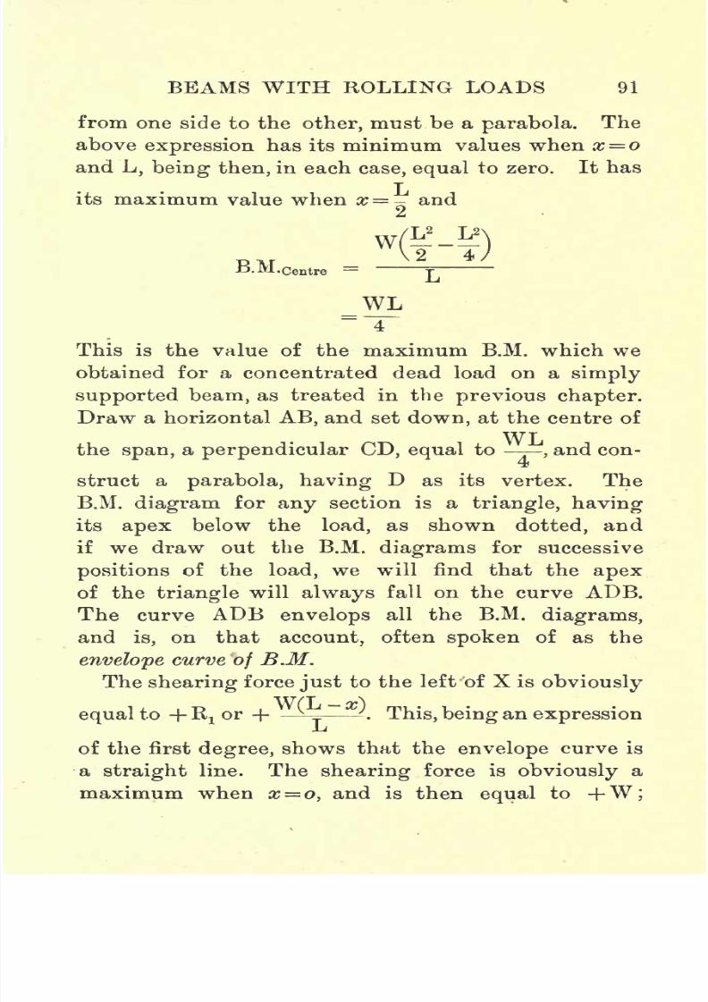
7/29/2019 Elementary Graphi 00wighrich
http://slidepdf.com/reader/full/elementary-graphi-00wighrich 107/256
BEAMS WITH ROLLING LOADS 91
from one side to the other, must be a
parabola.
The
above expression has its minimum values when x= o
and L, being then, in each case, equal to zero. It has
its maximum value when x=- and
B.M.Centre =
WL
This is the value of the maximum B.M. which we
obtained for a concentrated dead load on a simply
supported beam,as treated in the
previous chapter.Draw a horizontal AB, and set down, at the centre of
WLthe span, a perpendicular CD, equal to
,and con-
struct a parabola, having D as its vertex. The
B.M. diagram for any section is a triangle, having
its apex below the load, as shown dotted, and
if we draw out the B.M. diagrams for successive
positions of the load, we will find that the apex
of the triangle will always fall on the curve ADB.
The curve ADB envelops all the B.M. diagrams,
and is, on that account, often spoken of as the
envelope curve of B.M.
The shearing force just to the left of X is obviously
equal to +Rxor + L-i This, being an expressionL
of the first degree, shows that the envelope curve is
a straight line. The shearing force is obviously a
maximum when x= o, and is then equal to +W;

7/29/2019 Elementary Graphi 00wighrich
http://slidepdf.com/reader/full/elementary-graphi-00wighrich 108/256
92 ELEMENTARY GRAPHIC STATICS
when #= L the S.F. is
equalto zero. Draw a hori-
zontal line EF, and at E set up a line EG, equal to W,and join GF. The line GF is the envelope of the
positive shearing force. In the same way it can be
shown that the shearing force, just to the right of
the load, is equal to~
- W = -w ThisIj L
expression has its maximum value when #=L, and is
then equal to W, and when x= o its value is then
zero. We now set down from F a line FH, equal to
- W, and join EH. The line EH is the envelope of
the negative shearing force.
As the load rolls from R1
to R2
the variation
in the positive shearing force (or the shearing
force to the left of the load) is shown by the
triangle EGF, while the variation in the negative
shearing force (or the shearing force to the
right of the load) is shown by the triangle
EFH. It will be obvious that in
measuringthe shearing force at any section we must take
the maximum S.F., whether it be positive or
a egative.
It should be noted that, if we consider any section,
say X1?
the shearing force at that section will be
positiveif
Wis
approachingfrom R
2, while, if W
approaches from Rx ,the shearing force will then be
negative.
Uniformly Distributed Rolling Load. The next
case which we shall consider is that in which we
have a uniformly distributed load, weighing w Ibs.
per foot-run,and of
length
Lmoving
across a
simply
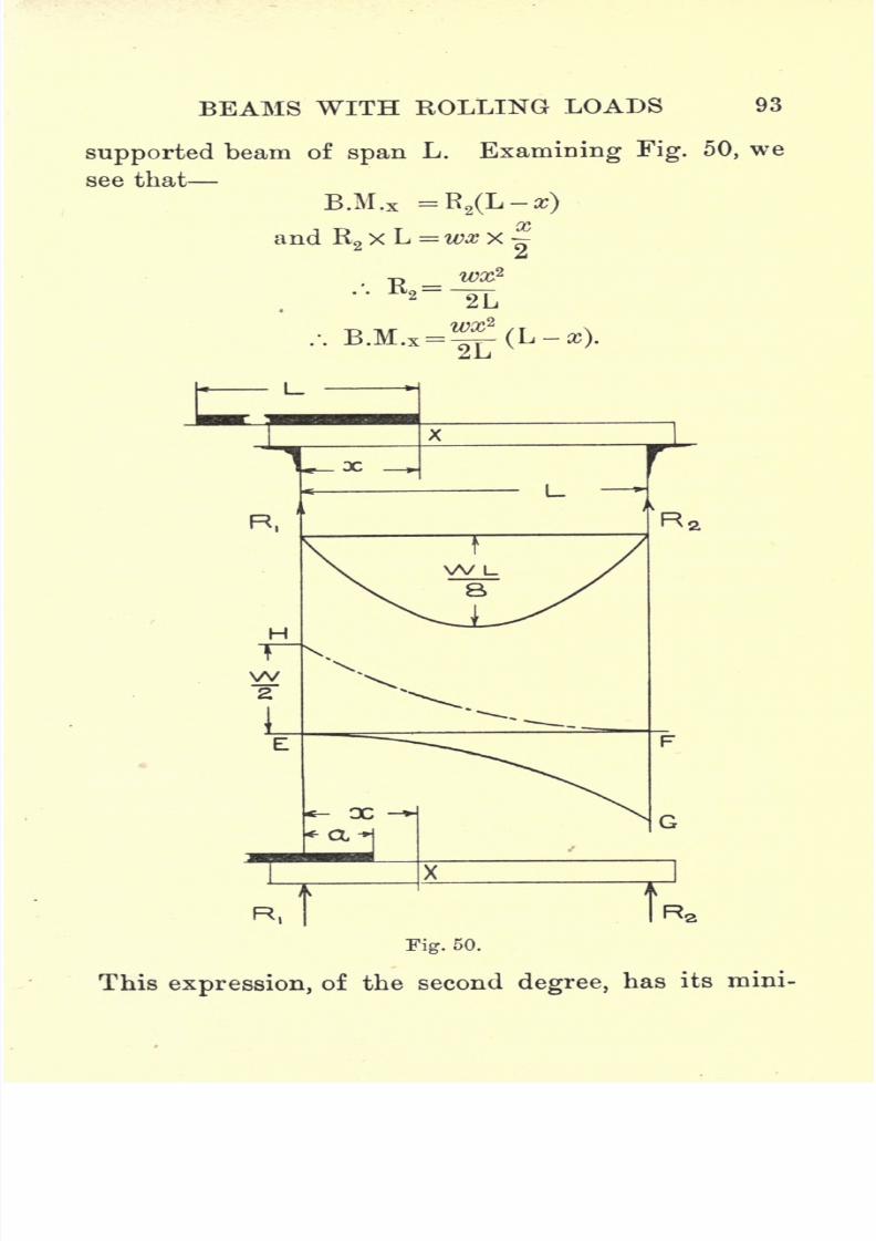
7/29/2019 Elementary Graphi 00wighrich
http://slidepdf.com/reader/full/elementary-graphi-00wighrich 109/256
BEAMS WITH ROLLING LOADS 93
supported
beam of
span
L. Examining Fig. 50, we
see that
B.M.x =R2(L-s)
SY*
and R2X L = wx x
JL
Fig. 50.
This expression, of the second degree, has its mini-
7/29/2019 Elementary Graphi 00wighrich
http://slidepdf.com/reader/full/elementary-graphi-00wighrich 110/256
94 ELEMENTARY GRAPHIC STATICS
mum values when x= o and L, being then, in each
case, equal to zero. The magnitude of the B.M.
gradually increases as the load moves from left to
right. The maximum B.M. occurs at the centre of
the span, when the span is fully loaded, and is then
WLequal to - -
;the parabolic curve, as shown, being
8
the envelope of maximum B.M. This is the value
of the maximum B.M. which we obtained for a
uniformly distributed load on a simply supported
beam, and hence the envelope curve of B.M. is
exactly similar to the B.M. curve for a simply
supported beam with a uniformly distributed load.
When we come to consider the S.F., we will
assume that the load has only travelled on to the
beam a distance a (see lower figure). The S.F. at X is
obviously equal to R2
.
Now R.xL
2L
The value of R2 obviously depends on the length
of a and increases as a increases. It will have its
greatest value when a becomes equal to x, or, in other
words, the S.F. at X will be a maximum when the
load fills the beam right up to the section. The
maximum S.F.X =^, and is negative. Theexpres-2L
sion shows the envelope curve of negative S.F. to be
7/29/2019 Elementary Graphi 00wighrich
http://slidepdf.com/reader/full/elementary-graphi-00wighrich 111/256
BEAMS WITH ROLLING LOADS 95
a parabola, and, when x = zero, the S.F. is zero, while,
when #=L,theS.F.is equal to,or ^ . It will be
2 2
noticed that as the load travels from left to right
the S.F. just in front of the load is negative. In
setting out the envelope curve,-we first draw a base
Wline EF, then set down FG- to represent ,
and
construct the parabolic curve as already explained.
If, on the other hand, the load had been travelling
from right to left, a little calculation will show that,
in this case, the S.F. just in front of the load is posi-
tive. The envelope curve of positive S.F. is shown in
the figure by EHF.
In many cases in practice we have, in addition to
a rolling load which may pass along the beam from
either side, certain dead loads fixed at definite points
on the span. Let us now consider the case, as shown
in Fig. 51, in which we have two dead loads, AB and
BC, acting on the beam in addition to a rolling load
of greater length than the beam which moves
from left to right. We first draw, by means of the
funicular polygon, the B.M. diagram for the dead
loads, as shown in pqrs. The envelope curve of B.M.
is next drawn for the rolling load, this being the
parabola uvw. These two diagrams are now com-
bined, by adding corresponding ordinates, to give
the combined B.M. diagram. From this latter curve
we can now determine the maximum B.M. and the
section at which it occurs.
It should be carefully noted that both of the B.M.
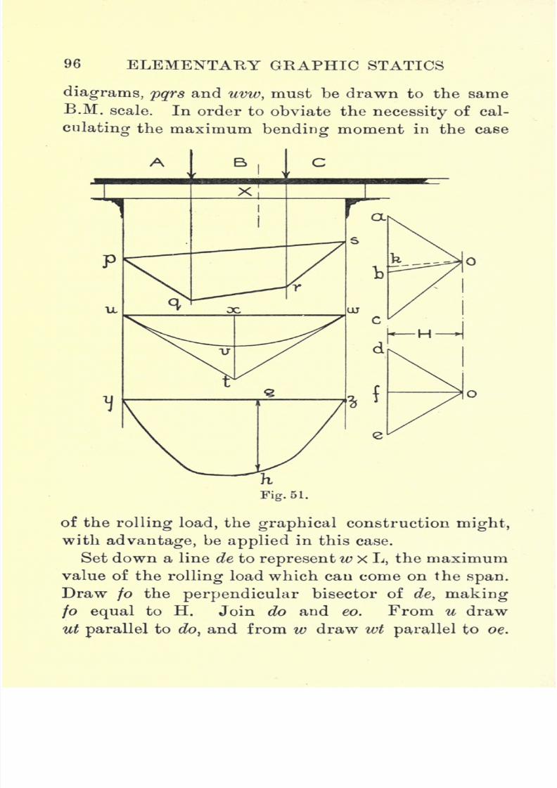
7/29/2019 Elementary Graphi 00wighrich
http://slidepdf.com/reader/full/elementary-graphi-00wighrich 112/256
96 ELEMENTARY GRAPHIC STATICS
diagrams, pqrs and uvw, must be drawn to the same
B.M. scale. In order to obviate the necessity of cal-
culating the maximum bending moment in the case
of therolling
load, thegraphical
constructionmight,
with advantage, be applied in this case.
Set down a line de to representw x L, the maximum
value of the rolling load which can come on the span.
Draw jo the perpendicular bisector of de, making
fo equal to H. Join do and eo. From u draw
utparallel
todo,
and from w draw wtparallel
to oe.

7/29/2019 Elementary Graphi 00wighrich
http://slidepdf.com/reader/full/elementary-graphi-00wighrich 113/256
BEAMS WITH ROLLING LOADS 97
Draw tx
perpendicularto uw and bisect it in v.
Using ut and wt as construction lines, construct the
parabola uvw, having its vertex at v.
--J c
Fig. 52.
Draw a new base line yz, and on this, by the addi-
tion of ordinates, as previously explained, construct
the combined diagram for the dead and rolling loads.
G

7/29/2019 Elementary Graphi 00wighrich
http://slidepdf.com/reader/full/elementary-graphi-00wighrich 114/256
98 ELEMENTARY GRAPHIC STATICS
The greatest B.M. which can occur at any section,
say X, is equal to gh, multiplied by the B.M. scale.
B.M.X = <7^ x m x n x H Ibs. feet.
The shape of the shearing force diagram will de-
pend on the direction of motion of the rolling load.
We first draw out the S.F. diagram for the dead loads,
then construct the diagram for the rolling load,
assuming it to move across the span first in the one
direction and then in the other.
By adding corresponding ordinates we can construct
the combined S.F. diagram. Fig. 52 shows the
required diagrams, the upper diagram representing
the case when the load moves from left to right, andthe lower diagram when it moves from right to
left.
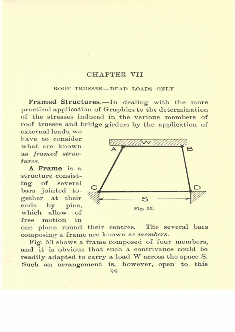
7/29/2019 Elementary Graphi 00wighrich
http://slidepdf.com/reader/full/elementary-graphi-00wighrich 115/256
CHAPTER VII
KOOF TEUSSES DEAD LOADS ONLY
Framed Structures. In dealing with the more
practical application of Graphics to the determination
of the stresses induced in the various members of
roof trusses and bridge girders by the application of
external loads, wehave to consider
what are known
as framed struc-
tures.
A Frame is a
structure consist-
ing of several
bars jointed to-
gether at their
Fig. 53.ends by pins,
which allow of
free motion in
one plane round their centres. The several bars
composing a frame are known as members.
Fig. 53 shows a frame composed of four members,
and it is obvious that such a contrivance could be
readily adapted to carry a load W across the space S.
Such an
arrangementis, however,
open
to this
99
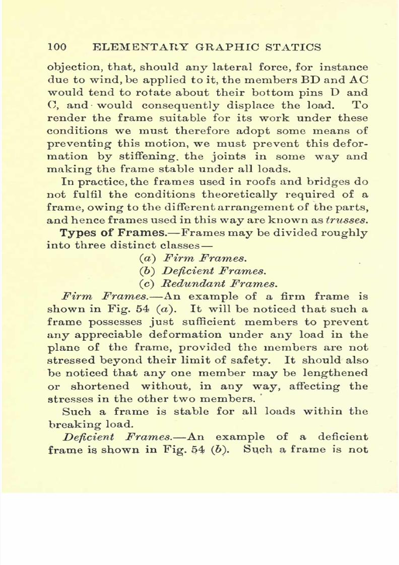
7/29/2019 Elementary Graphi 00wighrich
http://slidepdf.com/reader/full/elementary-graphi-00wighrich 116/256
100 ELEMENTARY GRAPHIC STATICS
objection, that, should any lateral force, for instance
due to wind, be applied to it, the members BD and ACwould tend to rotate about their bottom pins D and
0, and would consequently displace the load. To
render the frame suitable for its work under these
conditions we must therefore adopt some means of
preventing this motion, we must prevent this defor-
mation by stiffening, the joints in some way and
making the frame stable under all loads.
In practice, the frames used in roofs and bridges do
not fulfil the conditions theoretically required of a
frame, owing to the different arrangement of the parts,
and hence frames used in this way are known as trusses.
Types of Frames. Frames may be divided roughly
into three distinct classes
(a) Firm Frames.
(6) Deficient Frames.
(c) Redundant Frames.
Firm Frames. An example of a firm frame is
shown in Fig. 54 (a). It will be noticed that such a
frame possesses just sufficient members to prevent
any appreciable deformation under any load in the
plane of the frame, provided the members are not
stressed beyond their limit of safety. It should also
be noticed that any one member may be lengthened
or shortened without, in any way, affecting the
stresses in the other two members.
Such a frame is stable for all loads within the
breaking load.
Deficient Frames. An example of a deficient
frame is. shown, in
Fig.
54(b). Such a frame is not
7/29/2019 Elementary Graphi 00wighrich
http://slidepdf.com/reader/full/elementary-graphi-00wighrich 117/256
ROOF TRUSSES DEAD -LOAM OiST'LY'
101'
possessed of sufficient members to prevent deformation
on the application of a load. If we refer to our
remarks on the funicular polygon we will readily
see that there will be, at least, one system of forces
which will keep the members of the frame in the
given shape, but should one of these forces be altered,
the effect would be such that the frame, as presently
outlined by the members, would no longer coincide
with the link or funicular polygon, and hence an
alteration in shape would occur. Such a frame would
(oj (C)
therefore not be stable under all loads, but it could
be made so by the application of another member,
as shown dotted. Such an addition would convert
it into a firm frame, possessing stability under any
system of loading, in the plane of the frame, and
also possessing the further advantage that any one
member may yet be lengthened or shortened without
in any way affecting the stresses in the others.
Redundant Frames. An example of this type is
shown in Fig. 54(c).
A redundant frame may
possess one or more members more than is necessary
for stability, but it is stable under all loads, although
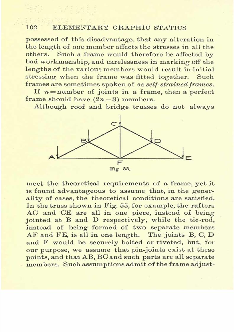
7/29/2019 Elementary Graphi 00wighrich
http://slidepdf.com/reader/full/elementary-graphi-00wighrich 118/256
102 ELEMENTARY GRAPHIC STATICS
possessed of this disadvantage, that any alteration in
the length of one member affects the stresses in all the
others. Such a frame would therefore be affected bybad workmanship, and carelessness in marking off the
lengths of the various members would result in initial
stressing when the frame was fitted together. Such
frames are sometimes spoken of as self-strained frames.
If n number of joints in a frame, then a perfect
frame should have (2n 3) members.
Although roof and bridge trusses do not always
meet the theoretical requirements of a frame, yet it
is found advantageous to assume that, in the gener-
ality of cases, the theoretical conditions are satisfied.
In the truss shown in Fig. 55, for example, the rafters
AC and CE are all in one piece, instead of being
jointed
at B and Drespectively,
while the tie-rod,
instead of being formed of two separate members
AF and FE, is all in one length. The joints B, C, Dand F would be securely bolted or riveted, but, for
our purpose, we assume that pin-joints exist at these
points,and that AB, BC and such parts are all separate
members. Suchassumptions
admit of the frame adjust-
7/29/2019 Elementary Graphi 00wighrich
http://slidepdf.com/reader/full/elementary-graphi-00wighrich 119/256
ROOF TRUSSES BEAD LOADS OKLY 103
ing itself, when loaded, so that all members are stressed
axially. Pin-jointed structures are more in use in
America than in this country, where the securely
riveted or bolted joint finds most favour. Rigid joints
give rise to bending stresses when the load comes on the
structure, but, generally speaking, unless the structure
be a very important one, such stresses are neglected.
Definitions. The primary duty of a roof truss is
to provide some means of support for the roofing
materials as used to exclude the weather from a
building. Trusses may be composed entirely of wood
or iron, or they may be combined of both materials.
A few terms in common use in connection with roof
trusses may be worthy of short explanations.
Roof Truss, or Principal, is the name given to
the framed structure complete without any roofing
material.
Pitch of the Principals is the horizontal distance P
between the centre lines of the trusses, as indicated
in the plan in Fig. 56.
Rafter is the name given to the parts marked RI}
R2 , etc., extending from the abutment to the apex and
providing support for the purlins. In the majority
of cases the rafters are in compression.
Purlins are the cross roof-bearers which are attached
to the rafters, the attachment being usually made bymeans of small pieces of angle-iron, known as cleats.
Struts and Ties. Strut is the name given to all
members subjected to a compressive stress, while all
members in tension are known as ties.
Pitch is the slope of the rafter measured in degrees
7/29/2019 Elementary Graphi 00wighrich
http://slidepdf.com/reader/full/elementary-graphi-00wighrich 120/256
104 ELEMENTARY GRAPHIC STATICS
from the horizontal. It depends on the nature of the
material used in the covering. A table of weights
of various roofing materials, together with minimum
pitches, is given later.
Distribution of Loading1
.- In dealing with the dead
loads acting on a roof truss these are, in general,
taken as acting vertically at the joints, and the
method of computing the magnitude of the loads at
these various points will now be considered,
Let us consider the roof as shown in plan and
elevation in Fig. 56. As shown by the shaded area
each truss, or principal, carries a piece of the roof
p
extending on either side of the centre line, so
that the total width of roof carried by one principal is
P, and if the length of each rafter be L ft., then the
total area of roof supported by one principal will be
(2L x P) sq. ft. Assuming the roofing material to
weigh w Ibs. per sq. ft., then the total load carried is
obviously (2L x P X w) Ibs., which, for convenience, we
can indicate as W. Now if this weight be uniformly
distributed over the roof, we can take it that each
section of the rafter gets an equal share of W.
We have four rafter members, Rp R2 ,R
3 ,R
4 ,and
Whence each one carries a load of Ibs., which we can
assume either acts through its centre of gravity or is
uniformly distributed along the member. This load,
acting on say Rp gives rise to reactions at 1 and 2
Weach equal to -
; similarly, the load on R2 gives rise
o

7/29/2019 Elementary Graphi 00wighrich
http://slidepdf.com/reader/full/elementary-graphi-00wighrich 121/256

7/29/2019 Elementary Graphi 00wighrich
http://slidepdf.com/reader/full/elementary-graphi-00wighrich 122/256
106 ELEMENTARY GRAPHIC STATICS
In dealing with the loads on a roof truss it must
not be forgotten that the truss itself may add very
considerably to the dead load, and hence it is neces-
sary that we have some means of approximating to
the weight of auy roof truss before the design is got
out. An approximate formula is given below-
Let ?= span in feet,
P = pitch of principals in feet,
W1=approximate weight in Ibs.
1=
*\
"
10/
Thefollowing
table
gives
the
weight per squarefoot of different roofing materials, together with the
minimum pitch at which they may be laid.
The following simple example, fully worked out,
may lead to a better understanding of the foregoing.
Example. A roof truss, of the type shown in Fig.
55, has a span of 30ft.,
the rafters being 16ft. long.

7/29/2019 Elementary Graphi 00wighrich
http://slidepdf.com/reader/full/elementary-graphi-00wighrich 123/256
ROOF TRUSSES DEAD LOADS ONLY . 107
The pitch of the, principals is 10ft.,
and the roof
is covered with in. boarding, and slates weighing
7*0 Ibs. per sq. ft.Determine what load comes on
each joint.
Our first step is to find the approximate weight of
the truss itself, and this is given by the formula
given above
-1x30x10
= fx 30x10x4
= 900 Ibs.
We must now determine the total weight of roofing
material per sq.ft.
Boarding, f in. thick, weighs 2'5 Ibs. per sq. ft.,
slates weigh 7'0 Ibs. per sq. ft., and purlins T5 Ibs.
per sq.ft.
Hence the total weight of roofing material per sq.
ft. equals 7'0+ 2'5+ l'5 = ll Ibs.
Now W =wx2LxP= 11x2x16x10= 3520 Ibs.
. . Total weight carried = Wx+Wby one truss= 900+ 3520
= 4420 Ibs.
This load is now divided up among the joints, ap-
portioning one part each to A and E, and two parts
7/29/2019 Elementary Graphi 00wighrich
http://slidepdf.com/reader/full/elementary-graphi-00wighrich 124/256
108 ELEMENTARY GRAPHIC STATICS
each to B, C and D; or, in other words, the load
must be divided into eight parts, hence
4,4,90
Each part=- =553 Ibs. (say)
8
. . Load at A and E = 553 Ibs. each.
. . Load at B, C, D= 1106 Ibs. each.
Simplest Form of Roof. With the exception,
perhaps, of the plain rafter as used in a lean-to roof,
the type shown in Fig. 57 is about the simplest form
with which we have to deal. The rafters are fastened
together at their top ends, and the bottom ends are
prevented from spreading by abutments on the
supporting walls, so designed as to be able to with-
stand the lateral thrust of the rafters.
The first operation is to set down, to some suitable
scale, the three joint-loads acting vertically down-
wards on the roof AB, BC and CD, in the line abed,
which is in reality the unclosed force polygon for
these three forces. In dealing with problems such
as the one above, it is advisable to adopt some con-
vention regarding the treatment of the various joints,
and the method adopted is to go round each joint in
a clockwise direction, each joint at a time, starting
from the left-hand side, and so form the polygon of
forces for each joint.
Starting then at the left-hand abutment, we are at
once beset with a difficulty, inasmuch as the reactions
are unknown in either magnitude or direction. Pass-
ing on, then, to the apex point, we find there are
three forces, of which one is known in magnitude
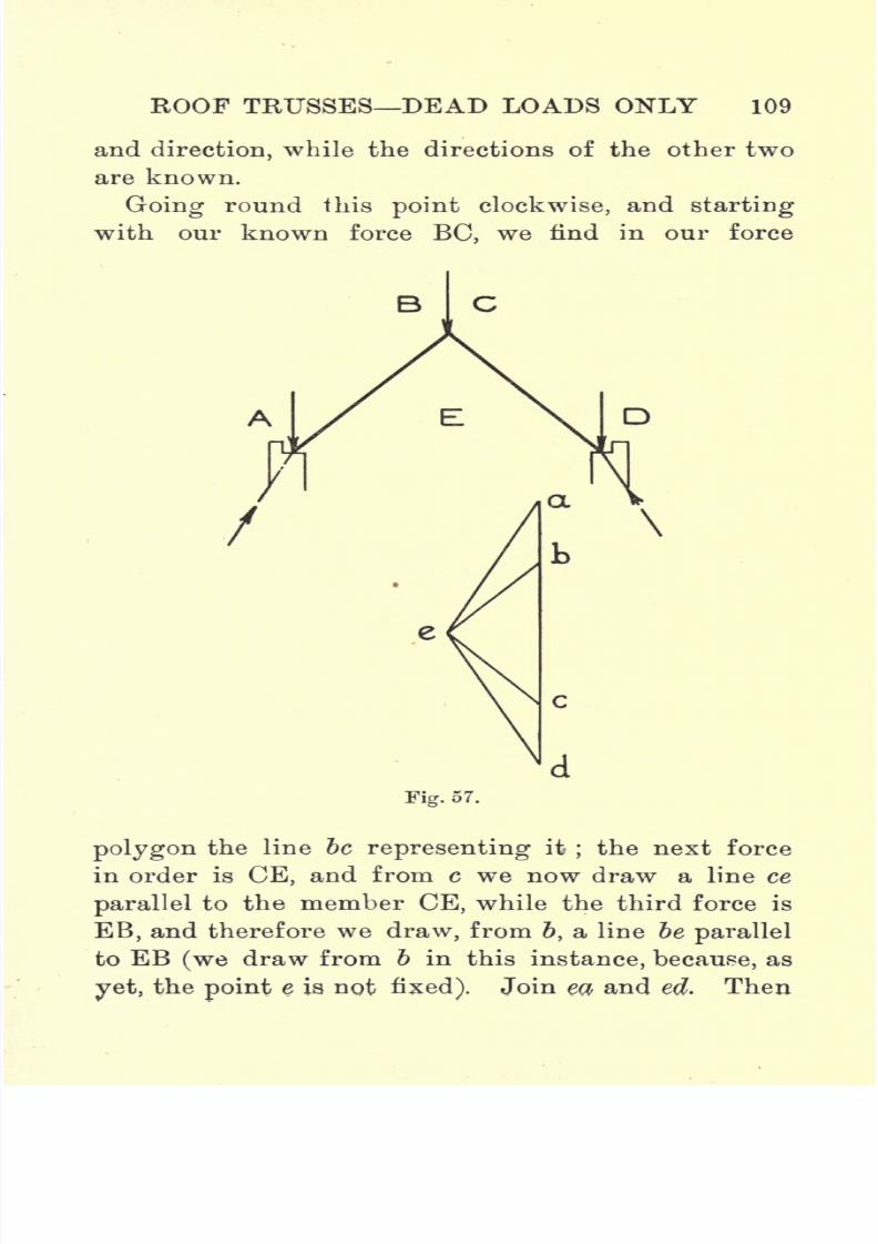
7/29/2019 Elementary Graphi 00wighrich
http://slidepdf.com/reader/full/elementary-graphi-00wighrich 125/256
ROOF TRUSSES DEAD LOADS ONLY 109
and direction, while the directions of the other two
are known.
Going round this point clockwise, and starting
with our known force BC, we find in our force
Fig. 57.
polygon the line be representing it;the next force
in order is CE, and from c we now draw a line ce
parallel to the member CE, while the third force is
EB, and therefore we draw, from 6, a line be parallel
to EB (we draw from b in this instance, because, as
yet,the
pointe is not fixed). Join eci> and ed. Then
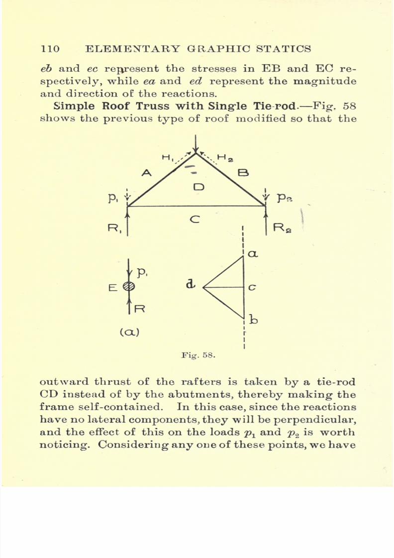
7/29/2019 Elementary Graphi 00wighrich
http://slidepdf.com/reader/full/elementary-graphi-00wighrich 126/256

7/29/2019 Elementary Graphi 00wighrich
http://slidepdf.com/reader/full/elementary-graphi-00wighrich 127/256
ROOF TRUSSES DEAD LOADS ONLY 111
a state of matters as shown in
Fig.58
(a).
We have a
point E acted on by a force R, which is the total
reaction at that point caused by the load on the
truss;and also by a force plt
in the same straight
line but in the opposite direction, so that the net
force acting on A is obviously (R-p1),
which force
we have called Rr
Thepoint
to be noted is this,
that, in a case where the reactions are perpendicular,
the vertical loads acting at the joints just over the
abutments, do not, in any way, affect the stress in the
various members, and may therefore be rejected, but
it should also be carefully noted that, as far as the
design of the supporting walls or columns is concerned,
this value Rxmust not be used, but the true value of
the reaction R, which equals (&i+ Pi).
In lettering our diagram then, we need consider
only the apex load AB. The construction of the
stress diagram does not call for much further explana-
tion. The load AB is represented by the line ab
drawn parallel and equal to it. From b we draw bd
parallel to BD, and from a we draw ad parallel to AD.
The force in the tie-rod is settled by going round one
of the reaction-points say R1. We have ad parallel
to AD, and our next force, going round clockwise, is
DC, hence we draw from d a line dc parallel to the
tie-rod. The lines bd and da give he loads in the
rafters;cd gives the load on the tie-rod
;while be
and ca give the values of the reactions R2and E
l
respectively.
In a simple case like this, it is an easy matter to
discriminate between ties and struts, but, in more
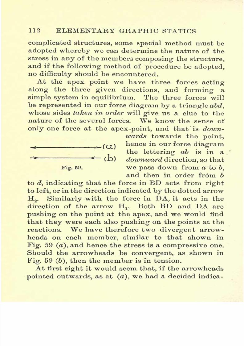
7/29/2019 Elementary Graphi 00wighrich
http://slidepdf.com/reader/full/elementary-graphi-00wighrich 128/256
112 ELEMENTARY GRAPHIC STATICS
complicatedstructures, some
specialmethod must be
adopted whereby we can determine the nature of the
stress in any of the members composing the structure,
and if the following method of procedure be adopted,
no difficulty should be encountered.
At the apex point we have three forces acting
alongthe three
given directions,and
forminga
simple system in equilibrium. The three forces will
be represented in our force diagram by a triangle abd,
whose sides taken in order will give us a clue to the
nature of the several forces. We know the sense of
only one force at the apex-point, and that^is down-
wards towards thepoint,
^/Q) hence in our force diagram
the lettering ab is in a<
(Jb) downward direction, so that
Fig. 59. we pass down from a to 6,
and then in order from b
to d,
indicatingthat the force in BD acts from
rightto left, or in the direction indicated by the dotted arrow
H2. Similarly with the force in DA, it acts in the
direction of the arrow H1
. Both BD and DA are
pushing on the point at the apex, and we would find
that they were each also pushing on the points at the
reactions. We have therefore twodivergent
arrow-
heads on each member, similar to that shown in
Fig. 59(a),
and hence the stress is a compressive one.
Should the arrowheads be convergent, as shown in
Fig. 59(6),
then the member is in tension.
At first sight it would seem that, if the arrowheads
pointed outwards,as at
(a),
we had a decided indica-

7/29/2019 Elementary Graphi 00wighrich
http://slidepdf.com/reader/full/elementary-graphi-00wighrich 129/256
ROOF TRUSSES DEAD LOADS ONLY 113
tion of tension, but
any difficulty
in the matter will
be easily overcome if we bear in mind that the arrow-
heads do not indicate the forces acting on the member,j
but serve as an indication of the manner in which the !
member itself acts on the joints at its extremities.
If therefore a member acts outwards on two joints,
then these joints must act inwards on the member, and
consequently it will be in compression.
The arrowheads on CO will be convergent, indicat-
ing tension, as is to be expected.
It is well to cultivate some system and order in
tabulating results, and the following method, as
indicated by Fig. 60, is, perhaps, as good as any.
Fig. 60.
Simple King-rod Truss. This truss is a simple
modification of the truss shown in the preceding
example, the addition being a light king-rod from
the apex to the centre of length of the horizontal
tie-rod. It will be found that the stress in this king-
rod is zero, showing it to be a redundant member,
whose only duty is to assist in supporting the
horizontal tie.
The rise is, in general, about one-fifth of the span,
and, since the rafters are unsupported at intermediate
points, this construction is unsuited for spans ex-
ceeding 20 feet.
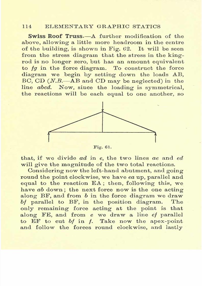
7/29/2019 Elementary Graphi 00wighrich
http://slidepdf.com/reader/full/elementary-graphi-00wighrich 130/256
114 ELEMENTARY GRAPHIC STATICS
Swiss Roof Truss. A further modification of theabove, allowing a little more headroom in the centre
of the building, is shown in Fig. 62. It will be seen
from the stress diagram that the stress in the king-
rod is no longer zero, but has an amount equivalent
to fg in the force diagram. To construct the force
diagramwe
begin by setting downthe loads
AB,BC, CD (N.B. AB and CD may be neglected) in the
line abed. Now, since the loading is symmetrical,
the reactions will be each equal to one another, so
Fig. 61.
that, if we divide ad in e, the two lines ae and ed
will give the magnitude of the two total reactions.
Considering now the left-hand abutment, and going
round the point clockwise, we have ea up, parallel and
equal to the reaction EA; then, following this, we
have ab down;the next force now is the one
actingalong BF, and from b in the force diagram we draw
bf parallel to BF, in the position diagram. The
only remaining force acting at the point is that
along FE, and from e we draw a line ef parallel
to EF to cut bf in/.
Take now the apex-point
and follow the forces round clockwise, and lastly

7/29/2019 Elementary Graphi 00wighrich
http://slidepdf.com/reader/full/elementary-graphi-00wighrich 131/256
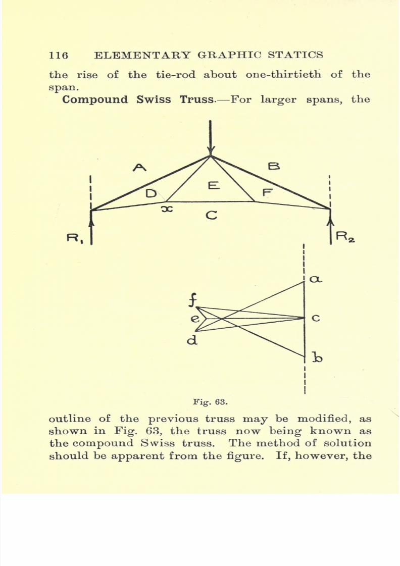
7/29/2019 Elementary Graphi 00wighrich
http://slidepdf.com/reader/full/elementary-graphi-00wighrich 132/256
116 ELEMENTARY GRAPHIC STATICS
the rise of the tie-rod about one-thirtieth of the
span.
Compound Swiss Truss. For larger spans, the
Fig. 63.
outline of the previous truss may be modified, as
shown in Fig. 63, the truss now being known as
the compound Swiss truss. The method of solution
should be apparent from the figure. If, however, the

7/29/2019 Elementary Graphi 00wighrich
http://slidepdf.com/reader/full/elementary-graphi-00wighrich 133/256
ROOF TRUSSES DEAD LOADS ONLY 117
apex-point be, taken just after the point over RI}
it
will be found that a difficulty arises, due to the fact
that the point e cannot be determined. It will be
readily seen that the solution is indeterminate,
since we have three unknown magnitudes to deal
with.
The difficulty can be got over by treating the point
x after Rxand by so doing getting the force triangle
cde; this makes it possible to construct the force
polygon abfed for the apex-point. It should be noted
that, in completing the force diagram, the line cf
forms a check line, for the points c and / are fixed,
and consequently the line cf must coincide with a
line through c parallel to CF.
Compound Swiss Truss with Right-angled
Struts. The struts are added to support the rafters
at their mid-points. They are at right angles to the
rafter, and on that account this truss is sometimes
known as the right-angled strut truss.
In drawing out the force diagram we are again
met with the difficulty experienced in the previous
case, but solution is possible by first treating the
point x, before passing on to the apex-point. Another
solution, though not strictly graphical, might easily
be adopted. We can fix the point h as soon as we
know the value of the tension in HE, and this can
be got very readily in the following manner :
Let T = tension in HE,
y= perpendicular distance from apex to HE,2S = span,
W = load at each joint.

7/29/2019 Elementary Graphi 00wighrich
http://slidepdf.com/reader/full/elementary-graphi-00wighrich 134/256
118 ELEMENTARY GRAPHIC STATICS
Taking moments about apex we have
R1 xS=(wx|)+(Txy),
.
T4=(B,xS)-fWx-|)=S/ Wx--
This tension can now be marked off in the force
Fig. 64.
diagram in the line eh, the point h being fixed in this
manner.

7/29/2019 Elementary Graphi 00wighrich
http://slidepdf.com/reader/full/elementary-graphi-00wighrich 135/256
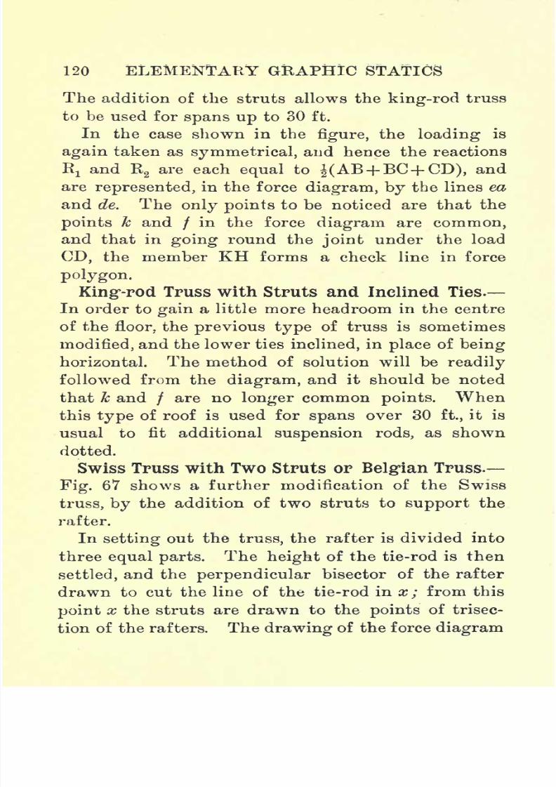
7/29/2019 Elementary Graphi 00wighrich
http://slidepdf.com/reader/full/elementary-graphi-00wighrich 136/256
120 ELEMENTARY GRAPHIC STATICS
The addition of the struts allows theking-rod
truss
to be used for spans up to 30 ft.
In the case shown in the figure, the loading is
again taken as symmetrical, and hence the reactions
R! and R2are each equal to J(AB+ BC+ CD), and
are represented, in the force diagram, by the lines ea
and de. Theonly points
to be noticed are that the
points k and / in the force diagram are common,
and that in going round the joint under the load
CD, the member KH forms a check line in force
polygon.
King-rod Truss with Struts and Inclined Ties.
In order to
gain
a little more headroom in the centre
of the floor, the previous type of truss is sometimes
modified, and the lower ties inclined, in place of being
horizontal. The method of solution will be readily
followed from the diagram, and it should be noted
that k and / are no longer common points. When
this
typeof roof is used for
spans
over 30 ft., it is
usual to fit additional suspension rods, as shown
dotted.
Swiss Truss with Two Struts or Belgian Truss.
Fig. 67 shows a further modification of the Swiss
truss, by the addition of two struts to support the
rafter.
In setting out the truss, the rafter is divided into
three equal parts. The height of the tie-rod is then
settled, and the perpendicular bisector of the rafter
drawn to cut the line of the tie-rod in x; from this
point x the struts are drawn to the points of trisec-
tion of the rafters. Thedrawing
of the force
diagram
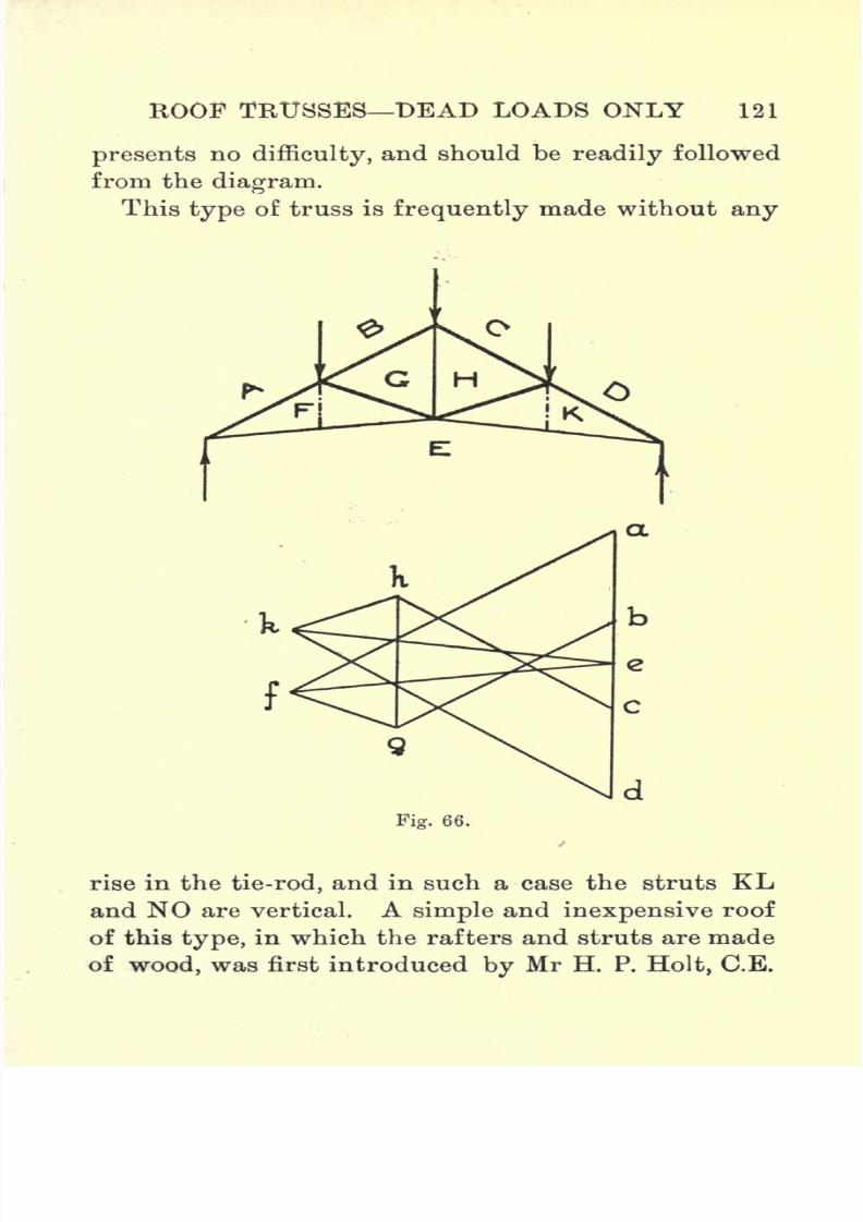
7/29/2019 Elementary Graphi 00wighrich
http://slidepdf.com/reader/full/elementary-graphi-00wighrich 137/256
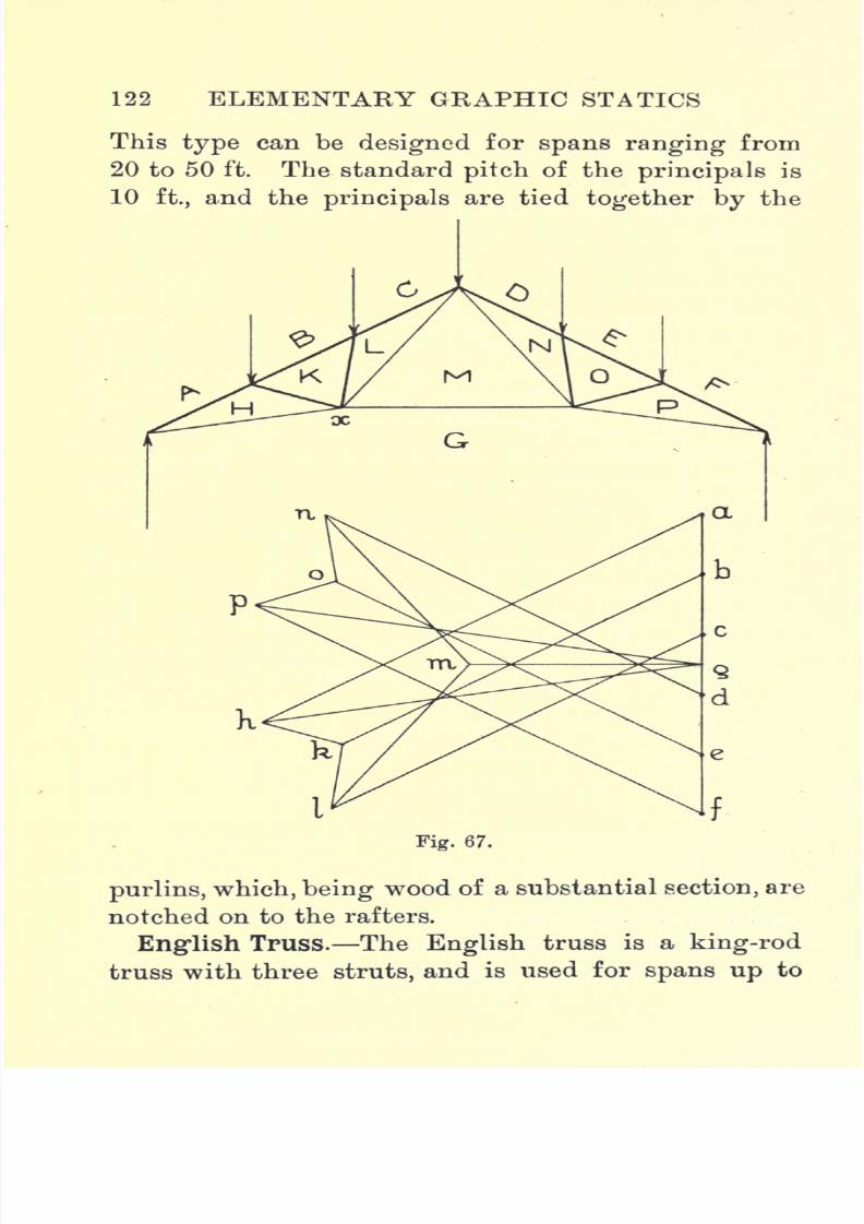
7/29/2019 Elementary Graphi 00wighrich
http://slidepdf.com/reader/full/elementary-graphi-00wighrich 138/256
122 ELEMENTARY GRAPHIC STATICS
This type can be designed for spans ranging from
20 to 50 ft. The standard pitch of the principals is
10 ft., and the principals are tied together by the
Fig. 67.
purlins, which, being wood of a substantial section, are
notched on to the rafters.
English Truss. The English truss is a king-rod
truss with three struts, and is used for spans up to

7/29/2019 Elementary Graphi 00wighrich
http://slidepdf.com/reader/full/elementary-graphi-00wighrich 139/256
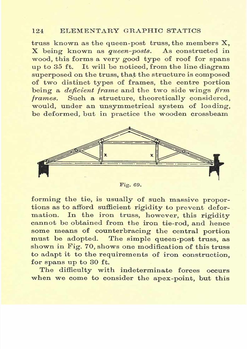
7/29/2019 Elementary Graphi 00wighrich
http://slidepdf.com/reader/full/elementary-graphi-00wighrich 140/256
124 ELEMENTARY GRAPHIC STATICS
truss known as thequeen-post
truss, the members X,
X being known as queen-posts. As constructed in
wood, this forms a very good type of roof for spans
up to 35 ft. It will be noticed, from the line diagram
superposed on the truss, that the structure is composed
of two distinct types of frames, the centre portion
beinga
deficient frameand the two side
wings firmframes. Such a structure, theoretically considered,
would, under an unsymmetrical system of loading,
be deformed, but in practice the wooden crossbeam
Fig. 69.
forming the tie, is usually of such massive propor-
tions as to afford sufficient rigidity to prevent defor-
mation. In the iron truss, however, this rigidity
cannot be obtained from the iron tie-rod, and hence
some means of
counterbracing
the central
portionmust be adopted. The simple queen-post truss, as
shown in Fig. 70, shows one modification of this truss
to adapt it to the requirements of iron construction,
for spans up to 30 ft.
The difficulty with indeterminate forces occurs
when we come to consider the
apex-point,
but this
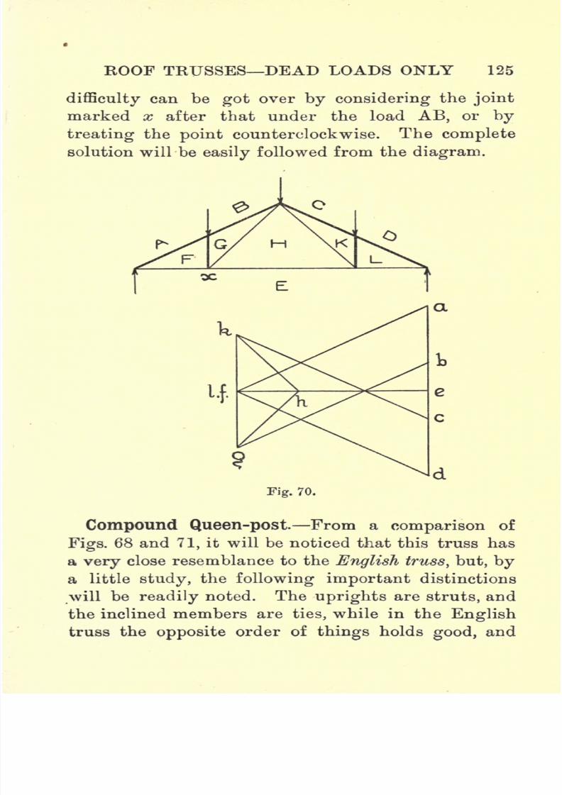
7/29/2019 Elementary Graphi 00wighrich
http://slidepdf.com/reader/full/elementary-graphi-00wighrich 141/256
ROOF TRUSSES DEAD LOADS ONLY 125
difficulty
can begot
over
by considering
thejoint
marked x after that under the load AB, or by
treating the point counterclockwise. The complete
solution will be easily followed from the diagram.
Fig. 70.
Compound Queen-post From a comparison of
Figs. 68 and 71, it will be noticed that this truss has
a very close resemblance to the English truss, but, by
a little study, the following important distinctions
will be readily noted. The uprights are struts, and
the inclined members are ties, while in the English
truss the opposite order of things holds good, and
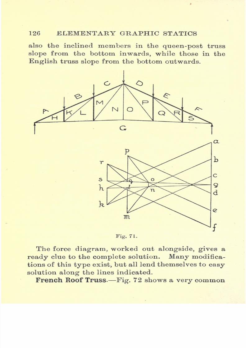
7/29/2019 Elementary Graphi 00wighrich
http://slidepdf.com/reader/full/elementary-graphi-00wighrich 142/256
126 ELEMENTARY GRAPHIC STATICS
also the inclined members in the queen-post truss
slope from the bottom inwards, while those in the
English truss slope from the bottom outwards.
7R
Fig. 71.
The force diagram, worked out alongside, gives a
ready clue to the complete solution. Many modifica-
tions of this type exist, but all lend themselves to easy
solution along the lines indicated.
French Roof Truss. Fig. 72 shows a very common
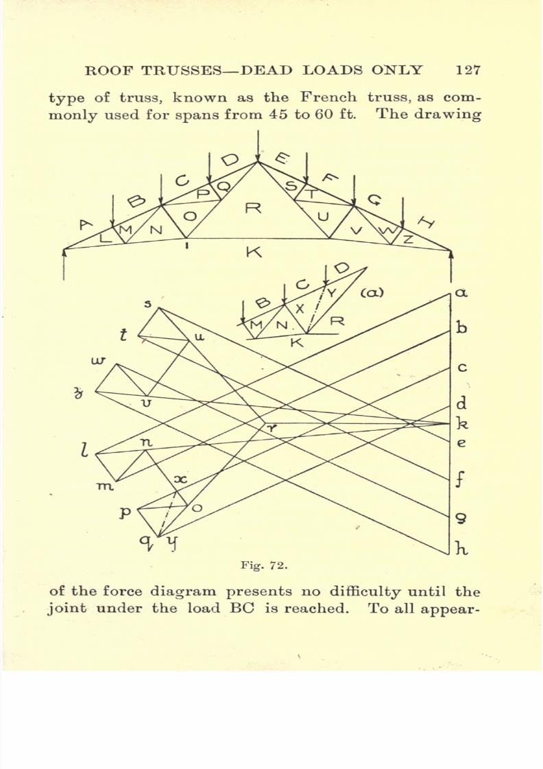
7/29/2019 Elementary Graphi 00wighrich
http://slidepdf.com/reader/full/elementary-graphi-00wighrich 143/256
ROOF TRUSSES DEAD LOADS ONLY 127
typeof
truss, knownas
the French truss,as com-
monly used for spans from 45 to 60 ft. The drawing
9
Fig. 72.
of the force diagram presents no difficulty until the
joint under the load BC is reached. To all appear-
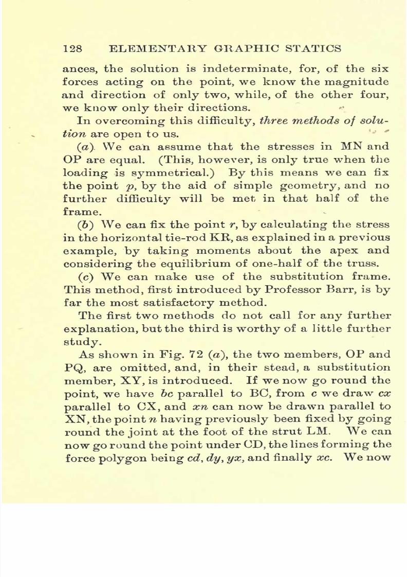
7/29/2019 Elementary Graphi 00wighrich
http://slidepdf.com/reader/full/elementary-graphi-00wighrich 144/256
128 ELEMENTARY GRAPHIC STATICS
ances, the solution is indeterminate, for, of the six
forces acting on the point, we know the magnitude
and direction of only two, while, of the other four,
we know only their directions.
In overcoming this difficulty, three methods of solu-
tion are open to us.
(a). We can assume that the stresses in MN and
OP are equal. (This, however, is only true when the
loading is symmetrical.) By this means we can fix
the point p, by the aid of simple geometry, and no
further difficulty will be met in that half of the
frame.
(6) We can fix the point r, by calculating the stress
in the horizontal tie-rod KR, as explained in a previous
example, by taking moments about the apex and
considering the equilibrium of one-half of the truss.
(c) We can make use of the substitution frame.
This method, first introduced by Professor Barr, is by
far the most satisfactory method.
The first two methods do not call for any further
explanation, but the third is worthy of a little further
study.
As shown in Fig. 72 (a),the two members, OP and
PQ, are omitted, and, in their stead, a substitution
member, XY, is introduced. If we now go round the
point, we have be parallel to BC, from c we draw ex
parallel to CX, and xn can now be drawn parallel to
XN, the point n having previously been fixed by going
round the joint at the foot of the strut LM. We can
now go round the point under CD, the lines forming the
force polygon being cd, dy, yx, and finally xc. We now

7/29/2019 Elementary Graphi 00wighrich
http://slidepdf.com/reader/full/elementary-graphi-00wighrich 145/256
ROOF TRUSSES DEAD LOADS ONLY 129
pass to the lowerjoint
marked 1, and form the force
polygon knxyrk. The members, OP and PQ, are now
replaced, and the forces acting at the joints are now
treated^ in the usual way, treating joint marked 1
before those unde"r EC and CD. No further difficulty
will be encountered until the joint under FG is
Fig. 74.
reached, but the difficulty is got over by making use
of the substitution member as before. The modifica-
tions of the French roof truss, as shown in Figs. 73
and 74, are adopted when this type of roof is used for
spans over 60 ft.
The student who has conscientiously worked
through all the preceding examples should now be
in a position to solve the above cases for himself.

7/29/2019 Elementary Graphi 00wighrich
http://slidepdf.com/reader/full/elementary-graphi-00wighrich 146/256
130 ELEMENTARY GRAPHIC STATICS
MansardRoof. Like the
queen-post truss,this
type of truss, when made of iron, although retaining
the same outline, differs considerably in the arrange-
ment of its members from the wooden truss which
bears the same name. Fig. 75 shows the Mansard
roof as constructed of timber, while Fig. 76 shows
the modifiedarrangement
of members when con-
structed of iron.
The difficulty of seemingly indeterminate forces
Fig. 75.
will again be met with at the joint under the load
AB, but the student should have now no trouble in
overcoming such difficulties.
Other modifications of the Mansard roof aregiven
in Figs. 77 to 80, but it is left to the student to solve
these for himself.
Examples.
1. A simple roof truss consists of two rafters and a
horizontal tie-rod connecting the ends which rest on
the abutments.The span
is 18 ft. and the rise 4 ft.
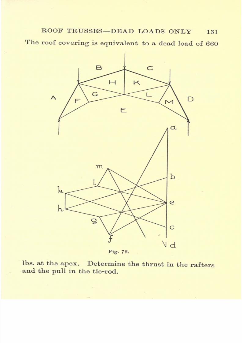
7/29/2019 Elementary Graphi 00wighrich
http://slidepdf.com/reader/full/elementary-graphi-00wighrich 147/256
ROOF TRUSSES DEAD LOADS ONLY 131
The roof
coveringis
equivalentto a
dead load of 660
Ibs. at the apex. Determine the thrust in the rafters
and the pull in the tie-rod.

7/29/2019 Elementary Graphi 00wighrich
http://slidepdf.com/reader/full/elementary-graphi-00wighrich 148/256

7/29/2019 Elementary Graphi 00wighrich
http://slidepdf.com/reader/full/elementary-graphi-00wighrich 149/256
ROOF TRUSSES DEAD LOADS ONLY 133
5 Ibs. per sq. ft., and the supports for the glass can
be taken as 1 J Ibs. per sq. ft. Determine the stresses
in the members.
5. A Belgian truss is used in roofing over an engine
shed. The span is 40 ft. and the rise to the apex 8
ft. The lower tie-rod has a rise of 18 ins. The pitch
of the principals is 10 ft. Boarding, 1 in. thick, is
used to carry slates weighing 8 Ibs. per sq. ft. The
purlins and fastenings can be taken as 1^ Ibs. per
sq. ft. Take into account the weight of the truss.
Determine the stresses in the various members, dis-
tinguishing carefully between ties and struts.
6. The shed in the above question was altered to
give a span of 60 ft., and English trusses were adopted
for the roof, the pitch of the principals being kept as
before. The height to the apex was 14 ft., and the
lower tie-rods rose to a point 2 ft. above the level
of the abutments. Determine the stresses in the
members, the roofing material being of the same
weight per sq. foot as before.
7. A compound queen-post truss carries a roof
over a span of 45 ft. The lower tie-rod is horizontal,
and the rise of the apex is 10 ft. The loads over the
abutments are each 500 Ibs., and at the other joints
1000 Ibs. Determine and tabulate the stresses.
8. A workshop roof is carried on French-roof
trusses. The span is 40 ft. and the rise to the apex
8 ft. The lower tie-rod has a rise of 18 ins., the
pitch of the principals being 8 ft. The roofing
material is No. 16 G. corrugated iron, weighing 3'5
Ibs. per sq. ft. The purlins and bearers can be taken
7/29/2019 Elementary Graphi 00wighrich
http://slidepdf.com/reader/full/elementary-graphi-00wighrich 150/256
134 ELEMENTARY GRAPHIC STATICS
as 1*5 per sq. ft. Taking into account the weight of
the truss, determine the stresses in the various
members.
9. A Mansard roof truss, as shown in Fig. 77, is
used for a roof having a span of 40 ft. The loads over
the abutments are each 600 Ibs., and at each of the
other joints 1200 Ibs. Determine the stresses induced
in the various members of the truss due to these
loads.
10. Assuming the same loading as given in Question
9, determine the stresses in the various members of
the roof trusses shown in Figs. 78, 79, 80. -The span
in each case can be taken as 50 ft., and the proportions
transferred from the diagrams.

7/29/2019 Elementary Graphi 00wighrich
http://slidepdf.com/reader/full/elementary-graphi-00wighrich 151/256
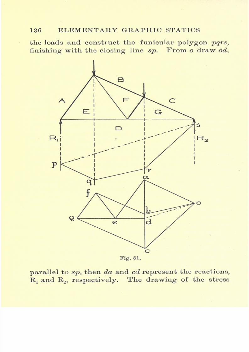
7/29/2019 Elementary Graphi 00wighrich
http://slidepdf.com/reader/full/elementary-graphi-00wighrich 152/256
136 ELEMENTARY GRAPHIC STATICS
the loads and construct the funicular polygon pqrs,
finishing with the closing line sp. From o draw od,
Fig. 81.
parallel to sp, then da and cd represent the reactions,
Rxand R
2 , respectively. The drawing of the stress

7/29/2019 Elementary Graphi 00wighrich
http://slidepdf.com/reader/full/elementary-graphi-00wighrich 153/256

7/29/2019 Elementary Graphi 00wighrich
http://slidepdf.com/reader/full/elementary-graphi-00wighrich 154/256
138 ELEMENTARY GRAPHIC STATICS
As before, the funicular polygon is made use of
in determining the reactions Rxand R2
. In drawing
out the stress diagram, difficulty will be experienced
at the joints under the loads BC and CD, the forces
acting at these points being seemingly indeterminate.
The difficulty can be got over by treating the joints
Fig. 83.
Fig. 84.
in the following order, viz., Rp AB, xv BC, x2 ,CD
and R2
. The difficulty at BC can also be overcome
bygoing round the joint counterclockwise, noting,
at the same time, that the point h must fall on
a horizontal through e, since eh is a horizontal
member.
Figs. 83 and 84 show further modifications of this
truss. The student is left to work out these cases
for himself. The finding of the reactions and the
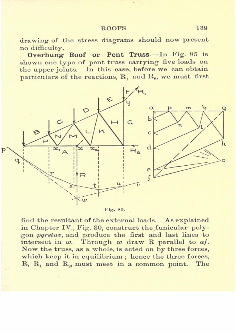
7/29/2019 Elementary Graphi 00wighrich
http://slidepdf.com/reader/full/elementary-graphi-00wighrich 155/256
ROOFS 139
drawing of the stress diagrams should now present
no difficulty.
Overhung Roof or Pent Truss. In Fig. 85 is
shown one type of pent truss carrying five loads on
the upper joints.In this case, before we can obtain
particulars of the reactions, Rtand R
2 ,we must first
Fig. 85.
find the resultant of the external loads. As explained
in Chapter IV., Fig. 30, construct the funicular poly-
gon pqrstuv, and produce the first and last lines to
intersect in w. Through w draw R parallel to af.
Now the truss, as a whole, is acted on by three forces,
which keep it in equilibrium ;hence the three forces,
R, Rxand R
2 ,must meet in a common point. The
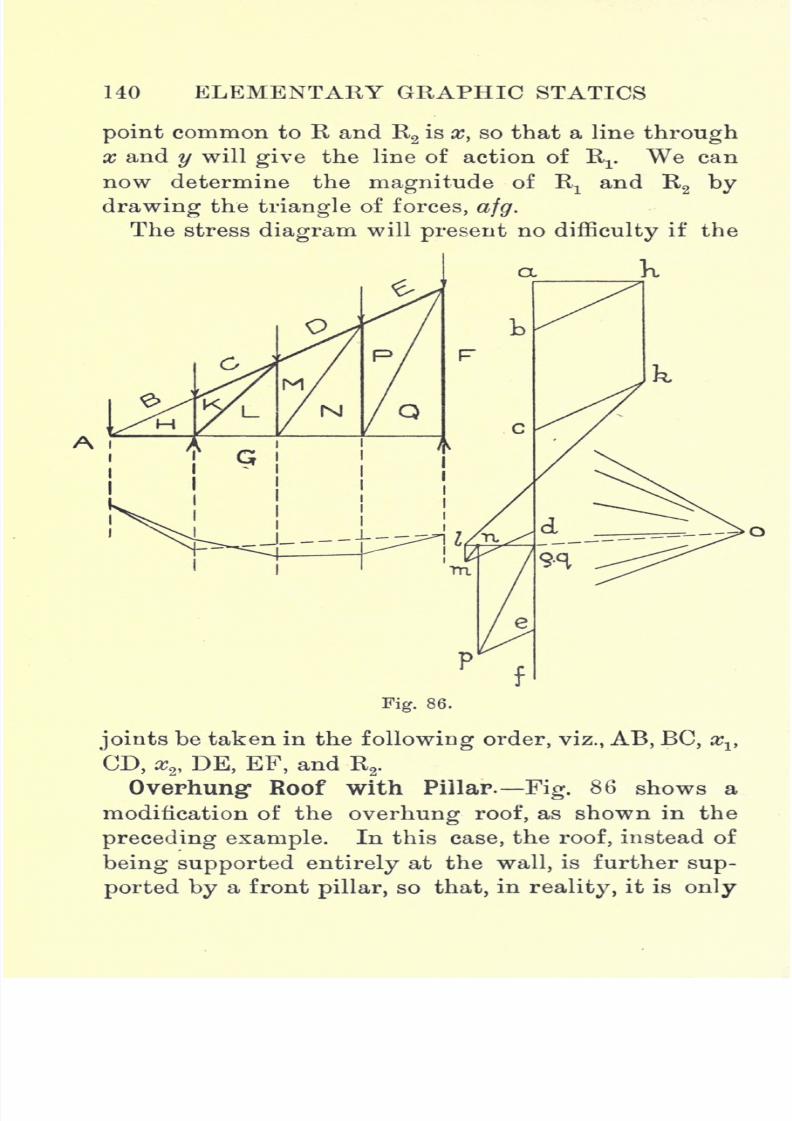
7/29/2019 Elementary Graphi 00wighrich
http://slidepdf.com/reader/full/elementary-graphi-00wighrich 156/256
HO ELEMENTARY GRAPHIC STATICS
point common to R and R2is x, so that a line through
x and y will give the line of action of Rr We can
now determine the magnitude of Rxand R
2 by
drawing the triangle of forces, afg.
The stress diagram will present no difficulty if the
Ai
Fig. 86.
joints be taken in the following order, viz., AB, BC, xv
CD, x2 , DE, EF, and R2
.
Overhung Roof with Pillar. Fig. 86 shows a
modification of the overhung roof, as shown in the
preceding example. In this case, the roof, instead of
being supported entirely at the wall, is further sup-
ported by a front pillar, so that, in reality, it is only
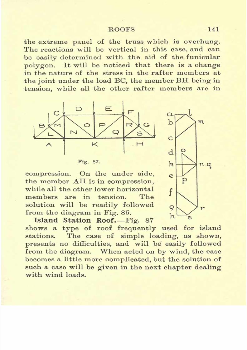
7/29/2019 Elementary Graphi 00wighrich
http://slidepdf.com/reader/full/elementary-graphi-00wighrich 157/256
ROOFS 141
the extreme panel of the truss which is overhung.
The reactions will be vertical in this case, and can
be easily determined with the aid of the funicular
polygon. It will be noticed that there is a change
in the nature of the stress in the rafter members at
the joint under the load BC, the member BH being in
tension, while all the other rafter members are in
N
K
Fig. 87.
m
compression. On the under side,
the member AH is in compression,
while all the other lower horizontal
members are in tension. The
solution will be readily followed
from the diagram in Fig. 86.
Island Station Roof. Fig. 87
shows a type of roof frequently used for island
stations. The case of simple loading, as shown,
presents no difficulties, and will be easily followed
from the diagram. When acted on by wind, the case
becomes a little more complicated, but the solution of
such a case will be given in the next chapter dealing
with wind loads.

7/29/2019 Elementary Graphi 00wighrich
http://slidepdf.com/reader/full/elementary-graphi-00wighrich 158/256
142 ELEMENTARY GRAPHIC STATICS
Examples.
1. A saw-tooth roof truss has the outline shown in
Fig. 81. The apex angle is 90 and the abutment
angles 60 and 30 respectively. The span is 22 ft.,
and the pitch of the principals is 8 ft. The member
FG is the perpendicular bisector of the longer rafter.
The longer side is covered with slates andboarding
weighing 12 Ibs. per sq. ft., while the shorter side
is covered with glass weighing 5 Ibs. per sq. ft.
Determine and tabulate the stresses in the various
members.
2. Draw out a roof truss similar to that shown in
Fig. 82, the anglesbeing
30, 60, and 90. The
span is 32 ft. and the pitch of the principals 10 ft.
Assuming the same type of covering as in Question
1, determine and tabulate the stresses in the various
members. Write down the value of the reactions Rx
and R2
.
3. Draw out a roof, as shown in Fig. 83, taking
the proportions from the diagram. With same load-
ing as in the above cases, determine the stress in the
members, if the span of the roof is 40 ft. and the
pitch of the principals 10 ft.
4. The roof of Question 3 was finally altered to
the shape shown in Fig. 84, all other things remain-
ing as before. Adopting the outline and proportions
of Fig. 84, determine and write down the stresses
in the members, and determine also the value of the
reactions.
5. An overhung station roof is arranged, as shown
in Fig. 85, the amount of overhang being 20 ft. The

7/29/2019 Elementary Graphi 00wighrich
http://slidepdf.com/reader/full/elementary-graphi-00wighrich 159/256
ROOFS 143
rafter makes an
angle
of 30 with the horizontal, and
is divided into four equal portions, being supported
at the joints by struts normal to the rafter. The
trusses are 8 ft. apart, and the roofing material
weighs in all 14 Ibs. per sq. ft. Determine the
stresses in the various members and the magnitude
and direction of the reactions.
6. Assuming the same truss as in Question 5, deter-
mine the stresses in the members and the reactions
when the total load on each truss is apportioned in
the following ratio
AB = 1, BC= 2, CD = 3, DE = 3'5, and EF= 1-5.
7. Fig. 86 shows the type of roof adopted for acertain railway station. The overhang is 40 ft. and
the pillar is 10 ft. from the outmost point. The
trusses are 10 ft. apart, and the roofing material
weighs 14'5 Ibs. per sq. ft. Determine the stresses
in the members and the magnitude of the reactions.
8.
An island station roof has the outline shownin
Fig. 87. The overall span is 40 ft. and the distance
between the pillars is 20 ft. The depth of the truss
is 10 ft. and the trusses are 10 ft. apart. Determine
the stresses in the members if the roofing material
weighs 12 Ibs. per sq. ft.
7/29/2019 Elementary Graphi 00wighrich
http://slidepdf.com/reader/full/elementary-graphi-00wighrich 160/256
CHAPTER IX
ROOF TRUSSES WIND PRESSURE
Calculation of Wind Pressure. So far, we have
been dealing with the effects produced on structures
by the application of dead loads only, but all
structures exposed to the weather are, more or less,
subjected to additional loads due to wind pressure,
which may be so great, in some cases, as to cause the
stresses induced by the dead loads to appear almost
negligible in comparison to those caused by the wind.
Many causes influence the pressure which the wind
exerts on a structure, and a mathematical solution of
the practical case is impossible. We can, however,
obtain an expression for. the force exerted by the
wind, if we make certain assumptions. Let us con-
sider a stream of air to impinge on a flat surface,
whose area is greater than the area of the stream,
and further let this surface be perpendicular to the
direction of the air stream, then the pressure exerted
on the surface can be deduced thus
Let P = air pressure in Ibs. per sq. ft.,
v velocity of air in ft. per second,
W =weight of air delivered per sq. ft. p. sec. in Ibs.,
w= weight of 1 cubic ft. of air in Ibs.
After impinging on the surface the air is assumed to
144

7/29/2019 Elementary Graphi 00wighrich
http://slidepdf.com/reader/full/elementary-graphi-00wighrich 161/256
ROOF TRUSSES WIND PRESSURE 145
have novelocity
normal to the surface. We have, in
general
Change of momen turn = impulsewxv = Pxt.
9
In our case, we are dealing with one second, and hence
t= unity ;we have therefore this relationship
P-*x*9
or expressed in words the pressure in Ibs. per sq.
ft. is equal to the change of momentum per second
occurring on that area. Now we are dealing with
1
sq.
ft. and an air
velocity
of v ft.
persecond, hence
the air delivered per sq. ft. per second will be v
cubic ft.
/. Weight of air delivered per second =wxv Ibs.
= W Ibs.
Now change of momentum p. sec. = x v.
g
_wv2
g
'
Putting in the values of w(= 0*08 Ibs.) and g
(=
32*2) and converting the velocity of the wind from
ft. per second into miles per hour, we get
08 xV2 x 5280x5280Change of momentum p. sec. =
-3600 x 3600 x3~2T2
= 0-0053V2,
where V = air velocity in miles per hour.
.-. P=0'0053V2Ibs. per sq. ft,
K
7/29/2019 Elementary Graphi 00wighrich
http://slidepdf.com/reader/full/elementary-graphi-00wighrich 162/256
146 ELEMENTARY GRAPHIC STATICS
Thus, with wind at a velocity of 40 miles per hour,
representing a moderate gale, the pressure in Ibs. per
sq. ft. would be 0'0053 X 40 x 40 = 8*5 Ibs., assuming
the above conditions could be attained in practice.
Experiments by Dr Stanton at the National Phy-
sical Laboratory go to show that the pressures, as
obtained by the above formula, are much too high.These experiments show that for rectangular surfaces
P = 0'0032V2Ibs. per sq. ft., no matter what area be
exposed to the force of the wind. For lattice-work
it was found that the pressure was much greater,
and that for structures of this nature P =0*00405V2
Ibs.per. sq. ft.
The effect of suction on the leeward side has an
important effect on the force which the wind exerts
on any structure, and this suction effect is found to
fall off rapidly as the length of the structure is
increased in the direction of the wind. Lattice-work,
presenting as it does innumerable thin,flat
platesto the wind, suffers increased pressures due to this
suction effect.
It can be taken generally that the steeper the
slope of a roof the greater will be the suction
effect on the leeward side, and hence the greater
the effective force on the windwardside.
Theexperiments at the Forth Bridge showed the effect
of the wind to increase with height above the
ground. The shape of the surface and its position
relative to other buildings are factors which
very materially affect the force exerted by the
wind.
7/29/2019 Elementary Graphi 00wighrich
http://slidepdf.com/reader/full/elementary-graphi-00wighrich 163/256
HOOF TRUSSES WIND PRESSURE 147
Maximum Wind Pressure. The maximum wind
pressure allowed on structures in this country was
for a long time taken as 40 Ibs. per sq. ft., and if
we make use of the theoretical formula which we
obtained, and calculate the pressure exerted by a
hurricane, which means a velocity of 90 miles per
hour, we find the windpressure
to be about 41 Ibs.
per sq. ft.
Following the inquiry after the Tay Bridge
disaster, the Board of Trade appointed a Committee
to investigate the effect of wind pressure on railway
bridges, and, as a result of the Committee's investiga-
tions, the B.O.T. recommended that in all designs of
railway bridges allowance should be made for a
maximum wind pressure of 56 Ibs. per sq. ft. This
figure, although seemingly high, readily justifies
itself in cases where the structure is in an exposed
situation, subjected to sudden gusts of wind, and
more so when life and limb are dependent on the
stability of the structure. In roof design, however,
experiment has shown that it is hardly economical
to make allowance for a greater maximum pressure
than 40 Ibs. per sq. ft., and that, only in very exposed
situations. It is, however, only the component of
this force normal to the roof surface which affects
the stresses in the members composing the roof truss.
In Continental practice it is usually assumed that
the wind acts at an angle of 10-15 to the horizontal,
but in this country the direction of the wind is
assumed horizontal. In determining the force exerted
normally to the roof surface, the most usual method
7/29/2019 Elementary Graphi 00wighrich
http://slidepdf.com/reader/full/elementary-graphi-00wighrich 164/256
H8 ELEMENTARY GRAPHIC STATICS
is to make use of Button's formula, which is as
follows :
P = force of the wind, on a surface at right angles
to its direction in Ibs. per sq. ft.,
Pn= normal pressure in Ibs. per sq. ft., on a surface
inclined to the direction of the wind,
&= angle of inclination of surface,
Then Pn =P(sin. &)1*4 cos e - 1.
When the wind blows horizontally, d is equal to the
slope or pitch of the roof.
Example. If the wiud, blowing horizontally, witha velocity corresponding to a pressure of 40 Ibs. per
sq. ft., impinges on a surface whose inclination to
the horizontal is 35, what will be the normal pressure
in Ibs. per sq. ft. ?
Pn =P (sinSin = sin 35 = 0'57 and cos = cos 35 = '82
;
.'.P =40(0-57)(l*4x-82)-l,
= 30 Ibs. per sq. ft.
It is not usual in this
countryto make
anyallow-
ance for snow, on the assumption that the snow load
is not likely to remain in the presence of the maxi-
mum wind load.
The following tables give the velocity of various
winds and the normal pressures on variously inclined
roofs for different horizontal
pressures.

7/29/2019 Elementary Graphi 00wighrich
http://slidepdf.com/reader/full/elementary-graphi-00wighrich 165/256
7/29/2019 Elementary Graphi 00wighrich
http://slidepdf.com/reader/full/elementary-graphi-00wighrich 166/256
150 ELEMENTARY GRAPHIC STATICS
then proceed to work out a few cases of combined
dead and wind loads.
The first point to be considered is the determina-
tion of the total wind pressure acting on the truss,
and this may be found thus
Let L= length of rafter in ft.,
p=pitch of principals
inft.,
P = normal wind pressure in Ibs. per sq. ft.,
W = total load due to wind, on anyone truss in Ibs.
Then W =LxpxP Ibs.
This load W is divided up among the joints along
the rafter, and if N be the number of spaces, then the
load on each end joint (i.e., the apex and abutment)
will be -Ibs., while the load on each intermediate
2N
Wjoint will be
-^-Ibs.
In finding the reactions we have three distinct
cases to deal with.
First Case. Both ends of the roof truss are at-
tached to the abutments by rigid fastenings, and
consequently the nature of the reactions is quite
indeterminate. It is, however, admissible to assume
them to act parallel to the resultant wind pressure.
We also assume that the resultant wind pressure
acts through the centre of length of the rafter. Pro-
duce the line of action of W, and through the joints
over the abutments draw two lines parallel to it.
Set down ab parallel to AB and equal to it, to scale.
Select a pole o, and join ao and bo. In the space A

7/29/2019 Elementary Graphi 00wighrich
http://slidepdf.com/reader/full/elementary-graphi-00wighrich 167/256
ROOF TRUSSES WIND PRESSURE 151
draw a line pq parallel to ao, and in the space B a line
qv parallel to bo. Draw the closing line pv, and from o
draw a line oc parallel to pv. Then ca and be give the
magnitudes of the reactions Rxand R
2 respectively.
Second Case. In this type the wind is blowing
from the right; the right-hand end of the truss is
anchored to the abutment, while the left-hand end is
mounted on a roller. This latter end is free to move,
hence it can adjust itself until the reaction is vertical.
w
Fig. 88.
We saw in Chapter II. that if three forces, acting
on a body, keep it in equilibrium, then these three
forces must act through a common point.
The frame shown in Fig. 89 is in equilibrium
under the action of three forces, viz., W, Rx ,R
2.
We know the directions of R! and W, Rx acting
vertically and W acting normally to the rafter
through its mid-point, but all we know of R2
is that
its line of action passes through P.
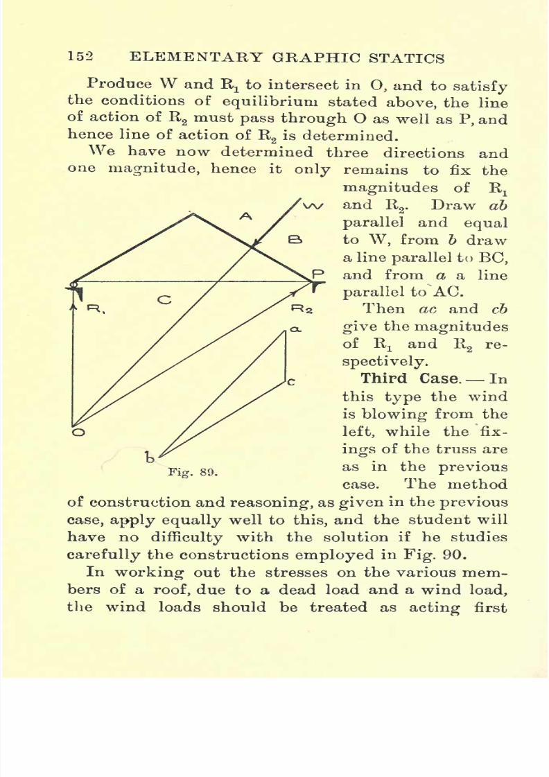
7/29/2019 Elementary Graphi 00wighrich
http://slidepdf.com/reader/full/elementary-graphi-00wighrich 168/256
152 ELEMENTARY GRAPHIC STATICS
Produce W and Rxto intersect in 0, and to satisfy
the conditions of equilibrium stated above, the lineof action of R
2must pass through O as well as P, and
hence line of action of R2is determined.
We have now determined three directions and
one magnitude, hence it thenly remains to fix
magnitudes of Rx
and R2 .
Draw ab
parallel and equal
to W, from b draw
a line parallel to BC,
and from a a line
parallel to AC.
Then ac and cb
give the magnitudes
of Rx
and R2
re-
spectively.
Third Case. In
this type the wind
is blowing from the
left, while the fix-
ings of the truss are
as in the previous
case. The method
of construction and reasoning, as given in the previous
case, apply equally well to this, and the student will
have no difficulty with the solution if he studies
carefully the constructions employed in Fig. 90.
In working out the stresses on the various mem-
bers of a roof, due to a dead load and a wind load,
the wind loads should be treated as acting first
p-
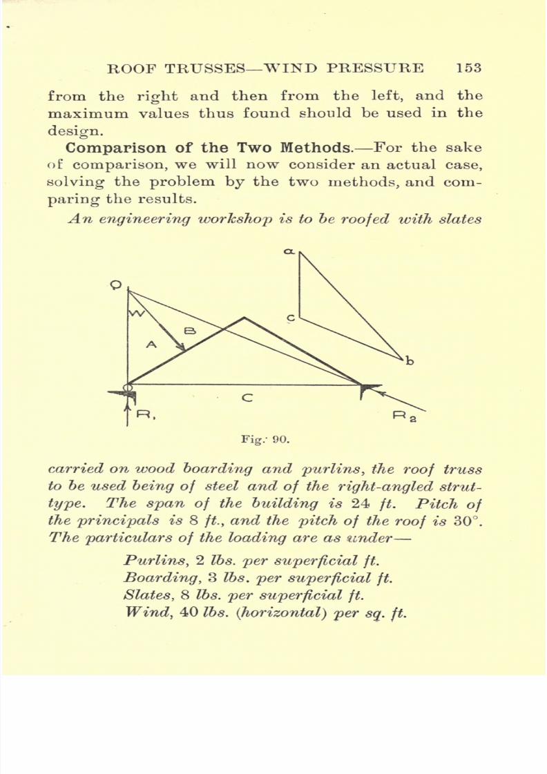
7/29/2019 Elementary Graphi 00wighrich
http://slidepdf.com/reader/full/elementary-graphi-00wighrich 169/256
ROOF TRUSSES WIND PRESSURE 153
from theright
and then from the left, and the
maximum values thus found should be used in the
design.
Comparison of the Two Methods. For the sake
of comparison, we will now consider an actual case,
solving the problem by the two methods, and com-
paring
the results.
An engineering workshop is to be roofed with slates
Fig: 90.
carried on wood boarding and purlins, the roof truss
to be used being of steel and of the right-angled strut-
type. The span of the building is 24ft. Pitch of
the principals is 8 ft, and the pitch of the roof is 30.The particulars of the loading are as under
Purlins, 2 Ibs. per superficial ft.
Boarding, 3 Ibs. per superficial ft.
Slates, 8 Ibs. per superficial ft.
Wind, 40 Ibs. (horizontal) per sq. ft.

7/29/2019 Elementary Graphi 00wighrich
http://slidepdf.com/reader/full/elementary-graphi-00wighrich 170/256
154 ELEMENTARY GRAPHIC STATICS
Approximate weight of truss
-489-6 Ibs. = 500 Ibs. say.
Length of rafter (from drawing)= 13*5 ft.
.-. Area of roof supported \ 1Q . K
by each principal /=
= 216 sq. ft.
.'. Dead load equals Purlins 216x2= 432
Boarding 216x3= 648
Slates 216x8 = 1728
2808
To allow for contingencies make dead load
3000 Ibs.
.*. Dead load, including truss =35001bs.=W.
. \ Load atj
oint over abutment =
= 440 Ibs.
.-. Load at intermediate joints=
= 880 Ibs.
Wind load acting horizontally= 40 Ibs. per sq. ft.
Pn =P (sin 6)1-84 cos 0-1
(0= 30)
log Pn =(1-84 cos 6-1) log sin 0+log P
={(l-84_x -86)
- 1} log 0-5 + log 40
= (58x1-699) +1-602
= 1-427
,-. Pn= 26'7 Ibs. per sq. ft., normal to roof.

7/29/2019 Elementary Graphi 00wighrich
http://slidepdf.com/reader/full/elementary-graphi-00wighrich 171/256
ROOF TRUSSES WIND PRESSURE 155
.'. Normal wind load on^ _ Q n Q .~ ^ >t7
i ni
f ^ X-"-^
" Xt\) I
one side of truss J
= 28801bs. =W2
/. Wind load at joint over'* _2880abutment and apex J 4~
= 7201bs.
/.Wind load at inter-) 2880mediate joint / 2
= 14401bs.
We can now set out these dead and wind loads at
the joints and proceed to construct the stress diagram
and so determine the maximum stress in the various
members. We will assume, in this case, that the
truss is fixed at both ends, and, in comparing the
two cases, we will deal first with the combined dead
and wind load. Referring to diagram No. 1, we
first set down all the external loads on the truss on
the load-line ak. Join the points a and k, and the
line ak represents the resultant of all the external
forces acting on the truss, its inclination giving
the direction of the resultant and, hence also, the
direction of the two reactions, Rxand R
2. Before we
can settle the magnitudes ofR.,^
and R2,we must
first find the point through which the resultant ak
acts. Now we know that the dead load is uniformly
distributed over the roof, and hence we can draw the
resultant of the dead loads(i.e., W) acting vertically
through the apex of the roof. Again we know that
the total wind load (i.e.,W
2)acts normally to one side
of the roof and is uniformly distributed over that
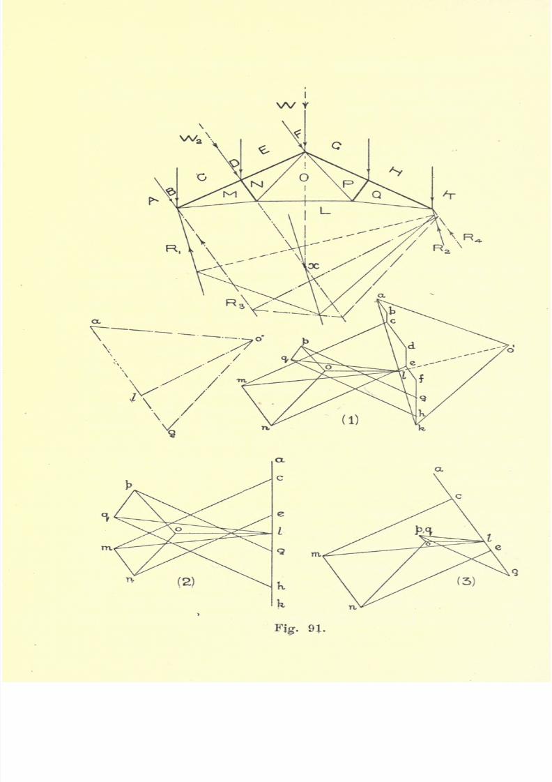
7/29/2019 Elementary Graphi 00wighrich
http://slidepdf.com/reader/full/elementary-graphi-00wighrich 172/256
I
wt
w.
Fig. 91.

7/29/2019 Elementary Graphi 00wighrich
http://slidepdf.com/reader/full/elementary-graphi-00wighrich 173/256
ROOF TRUSSES WIND PRESSURE 157
side, hence we can draw W2 ,
normal to the roof,
through the mid-point of the rafter. The lines of
action of these two loads will intersect in x, and x
is therefore a point on the line of action of the
resultant. We therefore draw through x a line
parallel to ok; Rxand K
2can be assumed to act
parallel to ak. Select a pole o', and join o'a and
o'lc ; draw the funicular polygon and complete
it with the dotted closing line, parallel to which
o'l is now drawn;
Id will equal R2and la will
equal RrThe drawing of the stress diagram should now
present no difficulty. The stresses should b'e scaled
oft' and tabulated. In dealing with the dead and
wind load separately, the same position diagram
has been used to economize space. In making use
of the lettering, the letter between the two forces
has been omitted, thus, when dealing with the dead
load, the load over the abutment becomes AC, the
letter B being omitted along with the wind load
AB. Similarly when dealing with wind loads we
again omit B, and the wind load at the abutment is
again AC.
Diagram No. 2 shows the stress diagram for dead
loads only. The wind load diagram, as shown in
diagram No. 3, calls for a little explanation. Whenthe wind load is acting alone, we can assume it to
be concentrated in a single force W2 acting normal
to the roof surface. The reactions (due to wind
alone) R3
- and R4
will therefore act parallel to
this line, and it now remains to determine the
7/29/2019 Elementary Graphi 00wighrich
http://slidepdf.com/reader/full/elementary-graphi-00wighrich 174/256
158 ELEMENTARY GRAPHIC STATICS
magnitudesof
R3 and R4.
Select a pole o" andjoin o"a and o"g. Draw the funicular polygon as
shown chain-dotted, finally drawing o"l parallel
to the closing line; gl will equal R
4and la will
equal R3.
Diagram No. 3 shows the stress diagram for the
windload,
and it will be noticed thatno
stress is
induced in the member PQ. Table I shows the
stresses as scaled off from diagram No. 1, while Table
II shows the stresses scaled off from diagrams Nos.
2 and 3. It will be seen that the figures, although
agreeing fairly closely, still show some slight dis-
crepancies.These latter
mightbe
accountedfor
byerrors in drawing, but there is another cause which
tends to bring about this difference. We made the
assumption that the directions of Rxand R
2were each
parallel to Jca, but, by combining the reactions, as
found from diagrams Nos. 2 and 3, we find that the
resultantreactions,
sofound,
do not coincide with
R! and R2 parallel to Tea. We could quite easily find
new values for Rxand R
2which would coincide with
the values obtained by the combination of the reactions
in diagrams Nos. 2 and 3. This would give a slightly
different position ofI, which would result in a slightly
modified stressdiagram. The
indeterminate nature
of the reactions, accentuated, to a large extent, by
the yielding nature of the supporting walls and the
twisting action of the fastenings, makes the exact
solution of this case impossible, and makes the
method adopted, in diagram No. 1, as justifiable as
anyother.

7/29/2019 Elementary Graphi 00wighrich
http://slidepdf.com/reader/full/elementary-graphi-00wighrich 175/256
ROOF TRUSSES WIND PRESSURE
TABLE I
159
TABLE II
Roof with Free-end. In the roof shown in Fig.
92, the right-hand end of the truss is carried on a
roller, while the left-hand end is anchored to the

7/29/2019 Elementary Graphi 00wighrich
http://slidepdf.com/reader/full/elementary-graphi-00wighrich 176/256
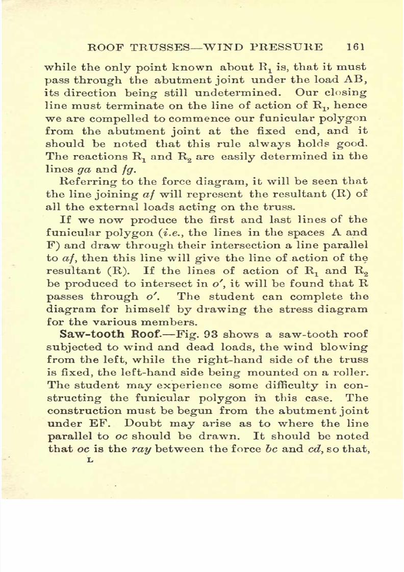
7/29/2019 Elementary Graphi 00wighrich
http://slidepdf.com/reader/full/elementary-graphi-00wighrich 177/256
ROOF TRUSSES WIND PRESSURE 161
while the only point known about El is, that it must
pass through the abutment joint under the load AB,
its direction being still undetermined. Our closing
line must terminate on the line of action of R1 ,hence
we are compelled to commence our funicular polygon
from the abutment joint at the fixed end, and it
should be noted that this rule always holds good.
The reactions Rxand R2
are easily determined in the
lines ga and fg.
Referring to the force diagram, it will be seen that
the line joining af will represent the resultant (R) of
all the external loads acting on the truss.
If we now produce the first and last lines of the
funicular polygon (i.e., the lines in the spaces A and
F) and draw through their intersection a line parallel
to af, then this line will give the line of action of the
resultant (R). If the lines of action of Rxand R
2
be produced to intersect in o', it will be found that R
passes through of
. The student can complete the
diagram for himself by drawing the stress diagram
for the various members.
Saw-tooth Roof. Fig. 93 shows a saw-tooth roof
subjected to wind and dead loads, the wind blowing
from the left, while the right-hand side of the truss
is fixed, the left-hand side being mounted on a roller.
The student may experience some difficulty in con-
structing the funicular polygon hi this case. The
construction must be begun from the abutment joint
under EF. Doubt may arise as to where the line
parallel to oc should be drawn. It should be noted
that oc is the ray between the force be and cd, so that,
L
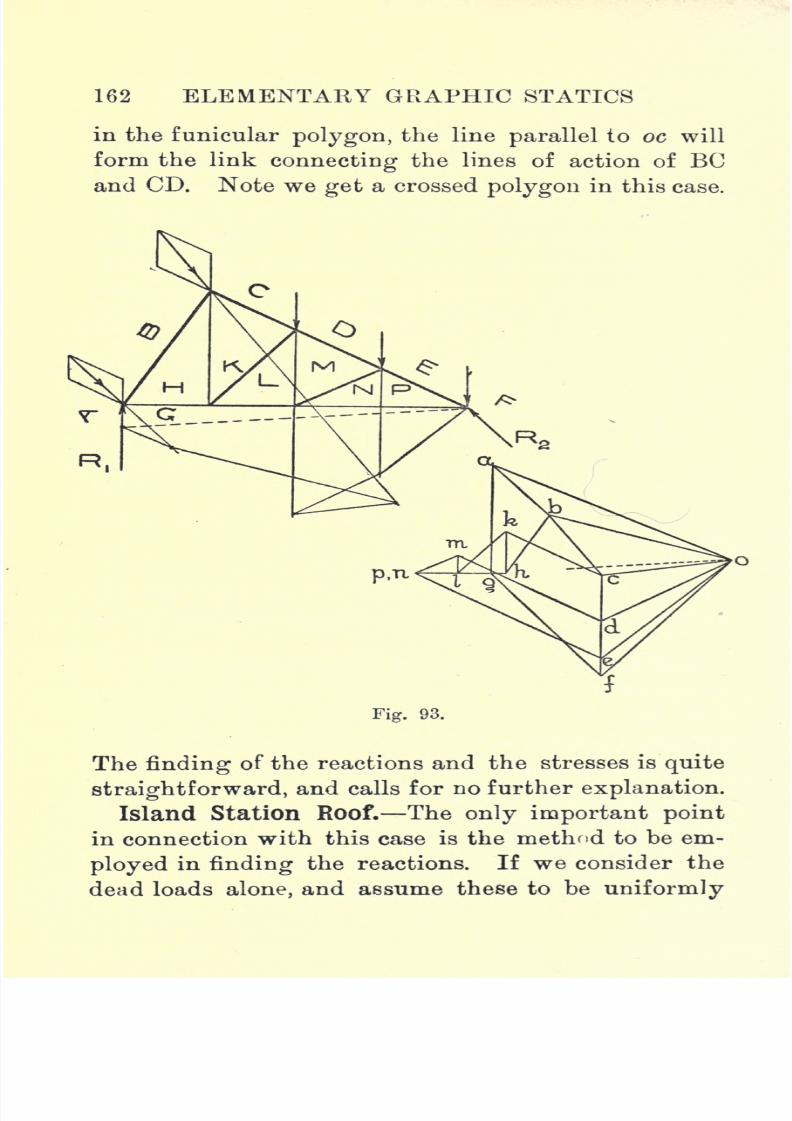
7/29/2019 Elementary Graphi 00wighrich
http://slidepdf.com/reader/full/elementary-graphi-00wighrich 178/256
162 ELEMENTARY GRAPHIC STATICS
in the funicular polygon, the line parallel to oc will
form the link connecting the lines of action of BC
and CD. Note we get a crossed polygon in this case.
Fig. 93.
The finding of the reactions and the stresses is quite
straightforward, and calls for no further explanation.
Island Station Roof. The only important point
in connection with this case is the method to be em-
ployed in finding the reactions. If we consider the
dead loads alone, and assume these to be uniformly
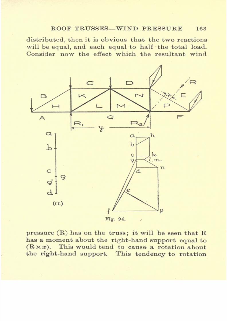
7/29/2019 Elementary Graphi 00wighrich
http://slidepdf.com/reader/full/elementary-graphi-00wighrich 179/256
ROOF TRUSSES WIND PRESSURE 163
distributed, then it is obvious that the two reactions
will be equal, and each equal to half the total load.
Consider now the effect which the resultant wind
(a)
Fig. 94.
pressure (R) has on the truss;
it will be seen that Rhas a moment about the right-hand support equal to
(Rx#). This would tend to cause- a rotation about
the right-hand support. This tendency to rotation

7/29/2019 Elementary Graphi 00wighrich
http://slidepdf.com/reader/full/elementary-graphi-00wighrich 180/256
164 ELEMENTARY GRAPHIC STATICS
is counterbalanced by a downward force (say R3)
acting at the left-hand support, distant y from the
right-hand support. Hence for equilibrium we must
have
The dead-load reaction at the left-hand support is
therefore diminished by R3.
. . R = i total dead load --- .
y
Coming now to the stress diagram, we now set
down the external loads in the line adf. Fig. 94 (a)
shows part of the load-line to an enlarged scale, and
it will readily be seen that, if we were considering
only dead loads, then g'a would give the reaction R1?
where g' is the mid-point of the complete load-line
(for dead loads only). Now let us suppose that the
resultant wind pressure (R)= 3600 Ibs.
;it will be
found from measurement that
J_4 ,hence R
3=
We therefore mark off g'g equal to 300 Ibs., then
ga equals the reaction Rr The reaction R2is obtained
by joining fg.The drawing of the stress diagram
presents no further difficulties.
It must not be forgotten when working out stresses
due to wind loads on roofs fixed at one end only, that
when the wind blows from the right, very different
7/29/2019 Elementary Graphi 00wighrich
http://slidepdf.com/reader/full/elementary-graphi-00wighrich 181/256
ROOF TRUSSES WIND PRESSURE 165
stresses will be obtained from those obtained when
the wind blows from the left. For purposes of
design, therefore, it is essential that the stresses be
obtained for the wind blowing from each direction,
and the maximum possible loads so obtained be used
in the design calculations.
7/29/2019 Elementary Graphi 00wighrich
http://slidepdf.com/reader/full/elementary-graphi-00wighrich 182/256
CHAPTER X
BRACED BEAMS AND GIRDERS
THE science of graphics finds another very useful
application in the solution of problems involving the
determination of the stresses in the various members
of braced structures used in bridge work. The load-
ings to which such structures are subjected depend
to a large extent on the purposes of the bridge, and
to some extent on the locality. It is not intended
to deal here with questions of loading, these being
adequately discussed in works on Structural Design.
Braced Beam with Single Stanchion. The
simplest case with which we have to deal is the
simple braced beam with single stanchion. An exami-
nation of Fig. 95 will show clearly that a beam
braced in this way is in reality an inverted king-
rod truss, with this important difference, that the
nature of the stresses in the various members is now
completely reversed;tension is changed to compres-
sion, and compression to tension.
Such a beam may be loaded in two different ways :
either with a single concentrated load directly over
the stanchion, or with a load distributed uniformly
over the whole length of the beam.
The solution in the first case does not call for any
166
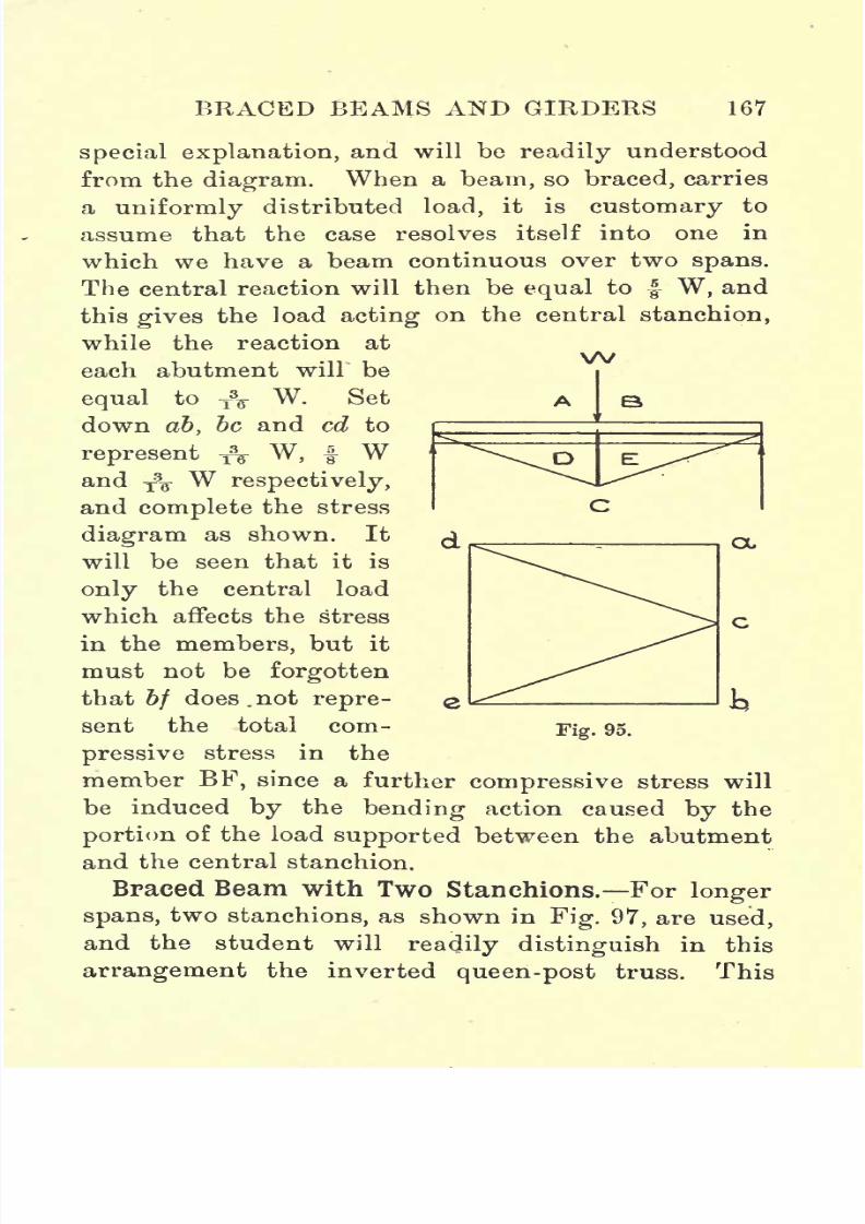
7/29/2019 Elementary Graphi 00wighrich
http://slidepdf.com/reader/full/elementary-graphi-00wighrich 183/256
BRACED BEAMS AND GIRDERS 167
special explanation,
and will bereadily
understood
from the diagram. When a beam, so braced, carries
a uniformly distributed load, it is customary to
assume that the case resolves itself into one in
which we have a beam continuous over two spans.
The central reaction will then be equal to | W, and
this
gives
the load
acting
on the central stanchion,
while the reaction at
each abutment will be
equal to T3F W. Set
down ab, be and cd to
represent A W, f Wand
f\
Wrespectively,and complete the stress
diagram as shown. It
will be seen that it is
only the central load
which affects the stress
in the members, but it
must not be forgotten
that bf does. not repre-
cx
Fig. 95.ent the total com-
pressive stress in the
member BF, since a further compressive stress will
be induced by the bending action caused by the
portion of the load supported between the abutment
and the central stanchion.
Braced Beam with Two Stanchions. For longer
spans, two stanchions, as shown in Fig. 97, are used,
and the student will readily distinguish in this
arrangement the inverted queen-post truss. This

7/29/2019 Elementary Graphi 00wighrich
http://slidepdf.com/reader/full/elementary-graphi-00wighrich 184/256
168 ELEMENTARY GRAPHIC STATICS
typeintroduces one or two
pointsof interest. If we
assume pin joints at the head of the stanchions,
it will at once be seen that the central panel is a
deficient frame, and in order to make it complete, an
additional member (shown dotted) will be required.
If, however, the loads over the stanchions are equal
andsteady,
it will be
"aw lew
B
,w
D
cc
Fig. 96.
truss,
seen, from the stress
diagram, that no
stress is induced in
FG, and hence, for
this particular case,
the additional dia-
gonal member is not
a necessity. By draw-
ing out the stress
diagram for unequal
loading it will be
seen that the diagonalthen becomes neces-
sary. For a variable
load both diagonals
must be added.
Trapezoidal Truss.
shown in Fig. 98, is ahe trapezoidalfurther modification of this type of beam, as
used for still longer spans. The same remark re-
garding the central panel applies in this case, and
for variable loading double counterbracing must be
added. Some difficulty will be experienced by the
student in solving this case, but the difficulty will be
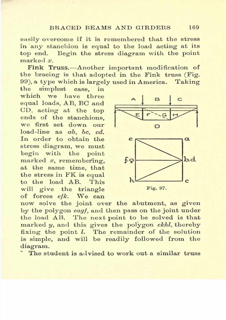
7/29/2019 Elementary Graphi 00wighrich
http://slidepdf.com/reader/full/elementary-graphi-00wighrich 185/256
BRACED BEAMS AND GIRDERS 169
D
easily
overcome if it is remembered that the stress
in any stanchion is equal to the load acting at its
top end. Begin the stress diagram with the point
marked x.
Fink Truss. Another important modification of
the bracing is that adopted in the Fink truss (Fig.
99), a type which is largely used in America. Takingthe simplest case, in
which we have three
equal loads, AB, BC and
CD, acting at the top
ends of the stanchions,
we first set down our
load-line as ab, be, cd.
In order to obtain the
stress diagram, we must
begin with the point
marked x, remembering,
at the same time, that
the stress in FK is equal
to the load AB. This
will give the triangle
of forces efk. We can
now solve the joint over the abutment, as given
by the polygon eagf, and then pass on the joint under
the load AB. The next point to be solved is that
marked y, and this gives the polygon ekTil, thereby
fixing the point I. The remainder of the solution
is simple, and will be readily followed from the
diagram.
The student is advised to work out a similar truss
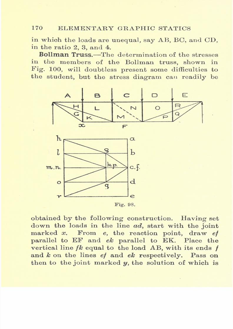
7/29/2019 Elementary Graphi 00wighrich
http://slidepdf.com/reader/full/elementary-graphi-00wighrich 186/256
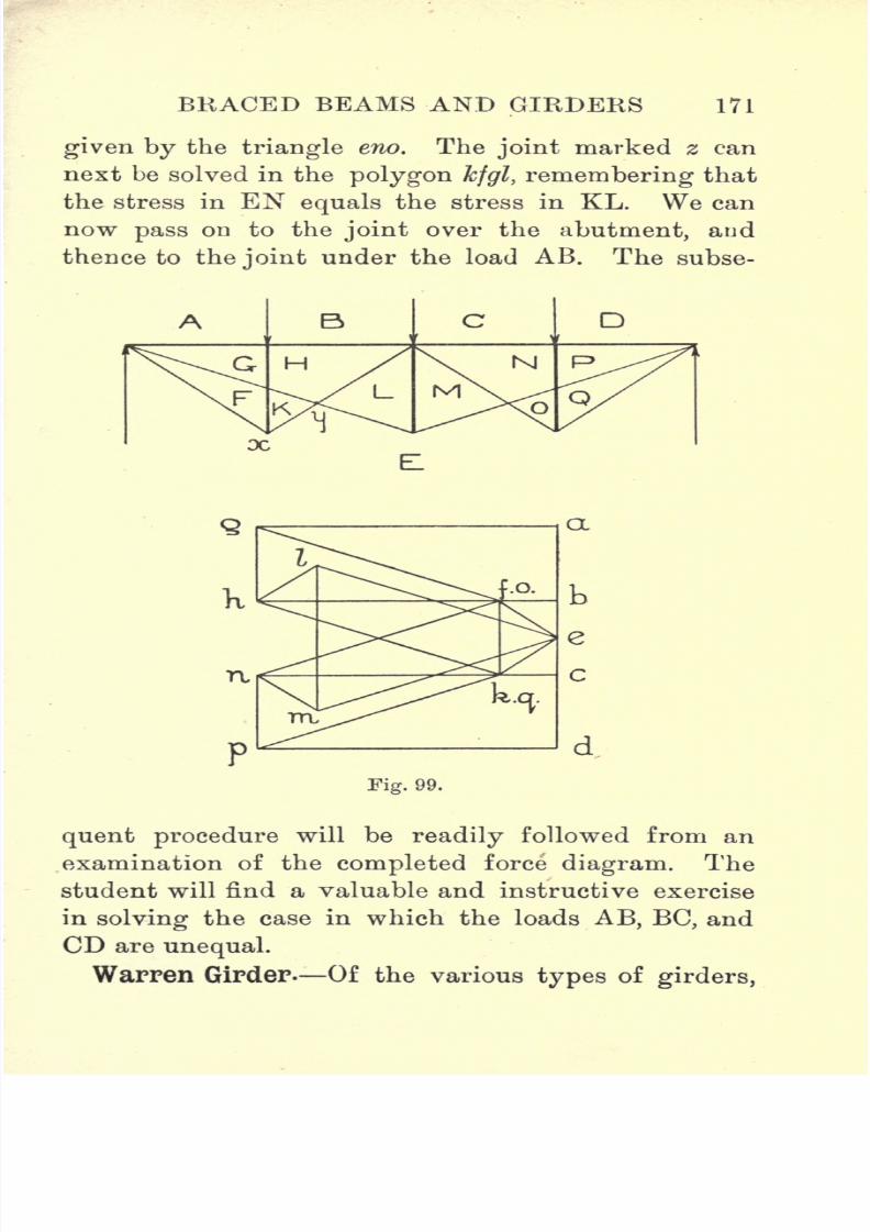
7/29/2019 Elementary Graphi 00wighrich
http://slidepdf.com/reader/full/elementary-graphi-00wighrich 187/256
BRACED BEAMS AND GIRDERS 171
given by the triangle eno. The joint marked z can
next be solved in the polygon kfgl, remembering that
the stress in EN equals the stress in KL. We can
now pass on to the joint over the abutment, and
thence to the joint under the load AB. The subse-
D
TV,
a
Fig. 99.
quent procedure will be readily followed from an
examination of the completed force diagram. The
student will find a valuable and instructive exercise
in solving the case in which the loads AB, BC, and
CD are unequal.
Warren Girder. Of the various types of girders,

7/29/2019 Elementary Graphi 00wighrich
http://slidepdf.com/reader/full/elementary-graphi-00wighrich 188/256
172 ELEMENTARY GRAPHIC STATICS
which are composed of top and bottom booms with
web bracing, probably the simplest and best known
is that invented by Captain Warren, and called, after
him, the Warren girder. The simplest form consists
of parallel top and bottom booms, with a single
triangulation system. These triangles are usually
Fig. 100.
equilateral, although this particular shape is not a
special feature of the girder ;but one important
point to note is, that in the Warren girder struts and
ties are all of equal length. There are various ways
in which a girder of this type may be arranged and
loaded, but it will be sufficient for our purpose to
consider only three cases.

7/29/2019 Elementary Graphi 00wighrich
http://slidepdf.com/reader/full/elementary-graphi-00wighrich 189/256
BRACED BEAMS AND GIRDERS 173
Case I. Single Concentrated Load.Fig.
101
shows a Warren girder of 5 bays, carrying a load Won the second joint from the top left-hand end.
Set down ab to represent W, and then fix the
position of c from a consideration of the position of
W. It will
readilybe seen that the line of action of
W produced will cut the lower boom in the ratio 1'5
to 3'5, hence, by taking moments, we can find the
value of the reactions, thus
R1x 5 =W x 3-5. R1==0-7W.
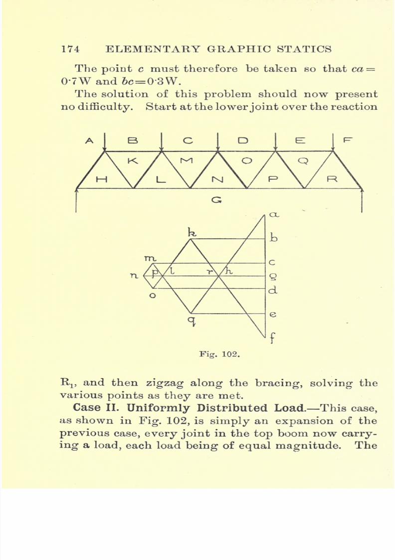
7/29/2019 Elementary Graphi 00wighrich
http://slidepdf.com/reader/full/elementary-graphi-00wighrich 190/256
174 ELEMENTARY GRAPHIC STATICS
Thepoint
c must therefore be taken so that ca =
0-7W and 6c=0'3W.
The solution of this problem should now present
nodifficulty. Start at the lowerjoint over the reaction
Fig. 102.
RI}and then zigzag along the bracing, solving the
various points as they are met.
Case II. Uniformly Distributed Load. This case,
as shown in Fig. 102, is simply an expansion of the
previous case, every joint in the top boom now carry-
ing a load, each load being of equalmagnitude.
The
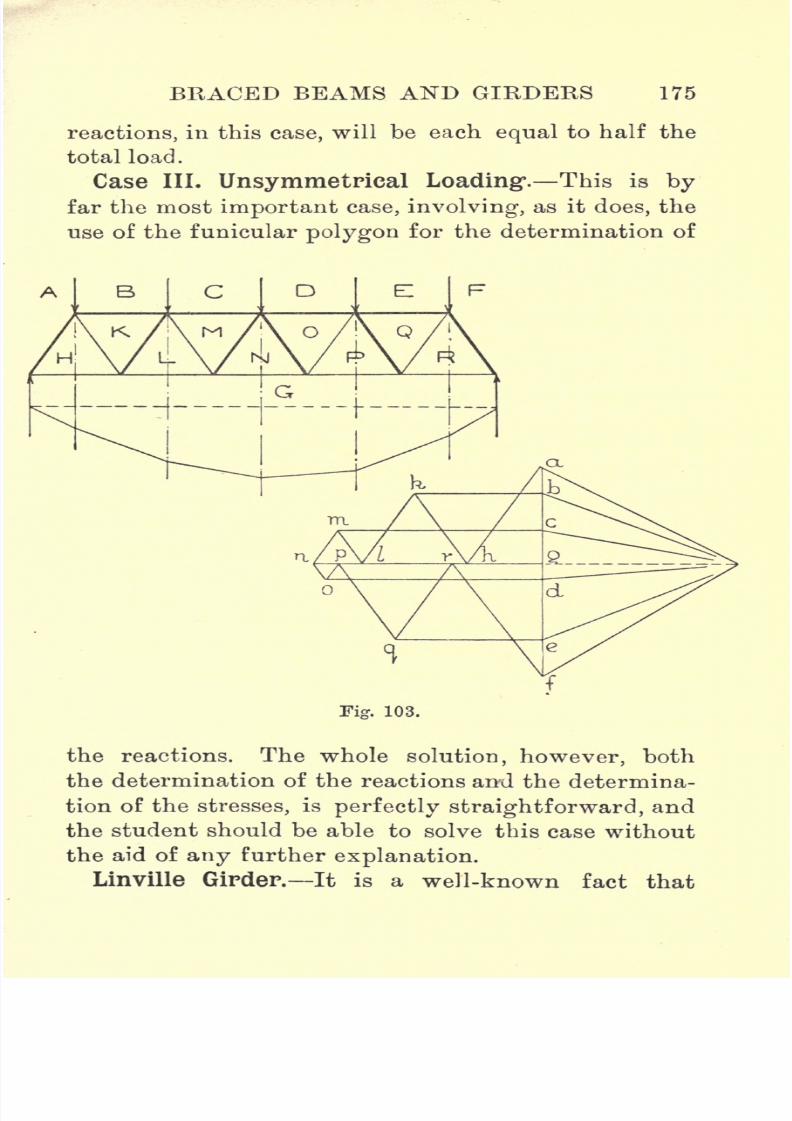
7/29/2019 Elementary Graphi 00wighrich
http://slidepdf.com/reader/full/elementary-graphi-00wighrich 191/256
BRACED BEAMS AND GIRDERS 175
reactions, in this case, will be each equal to half the
total load.
Case III. Unsymmetpieal Loading1
. This is by
far the most important case, involving, as it does, the
use of the funicular polygon for the determination of
the reactions. The whole solution, however, both
the determination of the reactions and the determina-
tion of the stresses, is perfectly straightforward, and
the student should be able to solve this case without
the aid of any further explanation.
Linville Girder. It is a well-known fact that

7/29/2019 Elementary Graphi 00wighrich
http://slidepdf.com/reader/full/elementary-graphi-00wighrich 192/256
176 ELEMENTARY GRAPHIC STATICS
while the strength of a tie-rod is not influenced byits length, the strength of a strut of a given section
increases as the length is decreased. In arranging
the members of a braced structure it will therefore be
economical to arrange that the members subjected to
compressive loads be made as short as possible. In
furtherance of this idea, the Linville truss was intro-
duced. It will be seen from Fig. 104 that the struts
in this truss are vertical, thus giving the shortest
possible length for any given depth of girder. In
determining the stress, we first set down the loads in
the line af and take the mid-point g, since the re-
actions are equal. We can then start with the joint
at the left-hand abutment, and zigzag along the
bracing, solving the joints as they come. This
method presents no difficulties until the joint at the
foot of the vertical NO is reached. The difficulty can,
however, be overcome by assuming that the stress in
the member MN is equal to the stress in the member
OP. We can, of course, fix the point if we remem-
ber that the stress in NO must be equal to CD; but,
by treating the joint under the load CD first, the
point is fixed without any assumptions which
might not be quite clear to the student. The re-
mainder of the solution is quite straightforward,
although, when the loading is symmetrical, it is un-
necessary to draw more than one-half of the stress
diagram.
Pratt Truss. Fig. 105 shows a modification of this
truss, known as the Pratt truss.
Lattice Girders. If we take two simple Warren

7/29/2019 Elementary Graphi 00wighrich
http://slidepdf.com/reader/full/elementary-graphi-00wighrich 193/256
BRACED BEAMS AND GIRDERS 177
girders,invert
oneof
them, and superposeit
onthe
other, we get an arrangement, as shown in Fig. lOfi,
which illustrates one type of lattice girder. The
fact that this type of girder is made up of two simple
girders suggests at once a method of treatment,
namely, to split the girder up into its components,
Fig. 104.
and solve eachsystem separately, finally adding
the
stresses together. This method, although more liable
to error, certainly has many advantages, but, in the
majority of cases, time can be saved and errors obvi-
ated by drawing one stress diagram to serve both
systems. The lattice girder shown in Fig. 106 is
subjected
to a
systemof
symmetricalloads, and hence
M

7/29/2019 Elementary Graphi 00wighrich
http://slidepdf.com/reader/full/elementary-graphi-00wighrich 194/256
178 ELEMENTARY GRAPHIC STATICS
the reactions will be eachequal
to half the total load.
We can therefore set down the load-line and select
k, the mid-point of its length. (In the diagram only
part of the load-line has been drawn to economize
space.)If we now attempt to draw the stress dia-
gram, we are at once beset with the difficulty that
every jointin the structure has
acting
on it a
systemof forces of which more than two facts are unknown.
Hence it would seem that the case is insoluble. If
Fig. 105.
we examine the inverted triangulation system of the
girder, it will be seen that this component supports
the loads AB, CD, EF and GH, and that the support-
ing forces are transmitted, from the abutments,
through the members AL and Ha. Therefore we
can say
Stress in
AL=AB+
CD
|
EFand
Stress in H = GH + .
2t
At the left-hand abutment we have a total reaction
KA, which is produced by two distinct loads, namely,
a downward load due to the uprightsystem,
trans-

7/29/2019 Elementary Graphi 00wighrich
http://slidepdf.com/reader/full/elementary-graphi-00wighrich 195/256
BRACED BEAMS AND GIRDERS 179
mitted direct to the abutment, and a downward load
due to the inverted system, transmitted to the abut-
ment through the member AL. We can therefore
calculate the stress in AL, and set it down as al
UJ.UL.t.
5
/v v7L
\
Fig. 106.
in the load-line;the point I coincides with c in this
case. No further difficulty will be met, if the joints
be treated in the following order : First go round
the point at the left-hand abutment, then pass up the
vertical to the joint under AB. Next pass along the
sloping member LM, solving first the joint at J;he
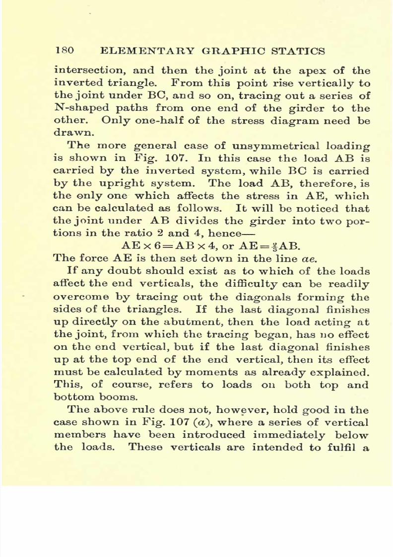
7/29/2019 Elementary Graphi 00wighrich
http://slidepdf.com/reader/full/elementary-graphi-00wighrich 196/256
180 ELEMENTARY GRAPHIC STATICS
intersection,and then the
jointat
the apexof
theinverted triangle. From this point rise vertically to
the joint under BC, and so on, tracing out a series of
N-shaped paths from one end of the girder to the
other. Only one-half of the stress diagram need be
drawn.
The moregeneral case of unsymmetrical loading
is shown in Fig. 107. In this case the load AB is
carried by the inverted system, while BC is carried
by the upright system. The load AB, therefore, is
the only one which affects the stress in AE, which
can be calculated as follows. It will be noticed that
thejoint
under
AB divides the girder into two por-tions in the ratio 2 and 4, hence
AE x 6=AB x 4, or AE= |AB.
The force AE is then set down in the line ae.
If any doubt should exist as to which of the loads
affect the end verticals, the difficulty can be readily
overcome by tracing out the diagonals forming thesides of the triangles. If the last diagonal finishes
up directly on the abutment, then the load acting at
the joint, from which the tracing began, has uo effect
on the end vertical, but if the last diagonal finishes
up at the top end of the end vertical, then its effect
must be calculated by moments as already explained.
This, of course, refers to loads on both top and
bottom booms.
The above rule does not, however, hold good in the
case shown in Fig. 107 (a), where a series of vertical
members have been introduced immediately below
the loads. These verticals are intended to fulfil a

7/29/2019 Elementary Graphi 00wighrich
http://slidepdf.com/reader/full/elementary-graphi-00wighrich 197/256
BRACED BEAMS AND GIRDERS 181
very important purpose, but whether the practical
results attained are in accordance with the assump-
tions made, is a question which is open to considerable
doubt. If we refer to Fig. 106, it will be seen that
the stresses in any two intersecting diagonals are
Fig. 107.
unequal, and the object to be attained by the intro-
duction of the vertical members is the equalization of
these stresses. The assumption is made that the
vertical member carries one-half of the load acting at
its top end. Thus, if we consider the load CD, it will

7/29/2019 Elementary Graphi 00wighrich
http://slidepdf.com/reader/full/elementary-graphi-00wighrich 198/256
182 ELEMENTARY GRAPHIC STATICS
be seen that, without the vertical member, the whole
of CD is carried by the inverted system ; while, when
the vertical member is added, the inverted system
CDonly carries -
,the other half being transmitted
along the vertical, and finally carried by the upright
system. When we come to consider all the loads
and their effect on AL, we could imagine the whole
of the bracing to be removed and the girder to consist
of rigid top and bottom booms separated by the end
verticals. One half of each of the loads BC, CD, DE,
EF and FG would now be transferred to the corre-
sponding points on the lower boom. The load on the
lower boom is carried direct by the abutments, while
the load on the upper boom is transmitted to the
abutments by the end verticals. The load on AL is
therefore equal to
BC.CD DE.EF FG
and this is now set down in the line al.
The same procedure as was followed in the previous
case is again adopted in drawing the stress diagram,
it being noted that the stress in any vertical is equal
to half the load at its top end. Thus, in the stress
diagram, we draw op vertical and mark off op equal
BCto-j,
Only a part of the stress diagram is shown, but it
is sufficient to show that the stresses in the inter-
secting diagonals are now equal.
The effect of the verticals is therefore to equalize
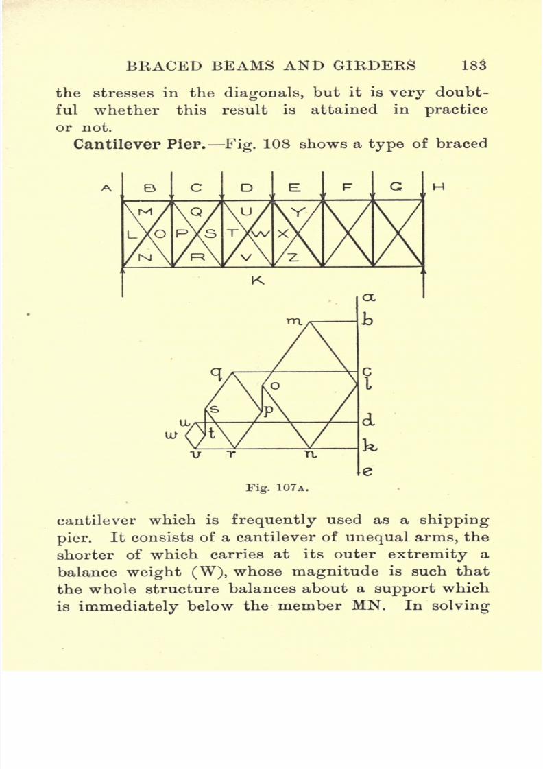
7/29/2019 Elementary Graphi 00wighrich
http://slidepdf.com/reader/full/elementary-graphi-00wighrich 199/256
BRACED BEAMS AND GIRDERS 183
the stresses in the diagonals, but it is very doubt-
ful whether this result is attained in practice
or not.
Cantilever Pier. Fig. 108 shows a type of braced
cantilever which is frequently used as a shipping
pier.It consists of a cantilever of unequal arms, the
shorter of which carries at its outer extremity a
balance weight (W), whose magnitude is such that
the whole structure balances about a support which
is immediately below the member MN. In solving

7/29/2019 Elementary Graphi 00wighrich
http://slidepdf.com/reader/full/elementary-graphi-00wighrich 200/256
184 ELEMENTARY GRAPHIC STATICS
this particular case we have first to find the magni-
tude of the back balance weight, and, in doing so, we
make use of the funicular polygon. The student will
doubtless experience a little difficulty in setting down
the loads, since, at the joint under MN, we have two
forces acting, namely, an upward force or reaction,
EF, which is equal to the sum of all the downward
loads, back balance included, and a downward force,
FG, equal to the load at the joint. In setting out the
load-line for the construction of the funicular polygon,
we delete the force EF and, with it, the letter F,
hence the downward force at the joint becomes EG,
and, as such, it appears in the load-line ah. Select a
pole o ; draw the rays and construct the funicular
polygon, the last link, parallel to oh, cutting the line
of action of W in the point x. Produce the first line
of the polygon bo cut the member MN in the point y.
Now the last line of the link polygon, when produced,
must pass through the points x and y, as shown. From
o draw oaf parallel to xy, and ha' gives the magni-
tude of the back balance which will cause the whole
structure to balance about the foot of the member
MN. The only point calling for explanation in the
stress diagram is the setting out of the load-line.
Replace the force, EF, which is of course equal to ofa.
Set down ab, be, cd, and de ; the next force is EF of
magnitude ofa, acting upwards, hence measure ef
upwards equal to a'a, then measure downwards fg
and gh, leaving ha the back balance weight acting
downwards. The remainder of the solution is quite
straightforward .

7/29/2019 Elementary Graphi 00wighrich
http://slidepdf.com/reader/full/elementary-graphi-00wighrich 201/256
BRACED BEAMS AND GIRDERS 185
Examples.
1. A trussed beam carries a load of 2 tons at the
Fig. 108.
centre of an 18-ft. span. The beam has a single
stanchion 2 ft. long directly under the load. Deter-
7/29/2019 Elementary Graphi 00wighrich
http://slidepdf.com/reader/full/elementary-graphi-00wighrich 202/256
186 ELEMENTARY GRAPHIC STATICS
mine the stresses in the stanchion and ties, and the
intensity of the compressive stress in the beam
material if the section is 9 ins. X 6 ins.
2. A bridge, 60 ft. span and 10 ft. wide, is supported
by two trusses of the type shown in Fig. 97. The
stanchions, which are 8 ft. long, divide the truss into
three equal divisions. The superstructure is attached
to the trusses at the abutments and at the head of the
stanchions, and the maximum load is equivalent to
180 Ibs. per sq. ft. Find the stresses in the various
members.
3. A trapezoidal truss has a span of 40 ft., and is
divided into four equal divisions by stanchions 5 ft.
long. The loads at the top of the stanchions, reading
from the left, are 2, 3, and 2 tons respectively. Find
the stresses in the members.
4. Assuming the loads in the previous case to be
2, 3 and 5 tons respectively, find the stresses in the
members and determine which diagonal must be sup-
plied to the central panel if the stress in the diagonal
is to be tension.
5. A Fink truss, 30 ft. long, has four equal divisions,
the stanchions being 4 ft. long. The load at the top
of each stanchion is 2 tons. Find the stresses in the
various members.
6. A railway bridge, crossing a river, has a span of
49 ft. The bridge is supported on two Fink trusses,
each divided into 7 bays of 7 ft. each. The depth of
the truss is 8 ft. It is estimated that the maximum
dead load is equivalent to 35 tons, while the maximum
live load is
equivalent
to 1J tons per ft. of length

7/29/2019 Elementary Graphi 00wighrich
http://slidepdf.com/reader/full/elementary-graphi-00wighrich 203/256
BRACED BEAMS AND GIRDERS 187
Find the maximum stress in the members and the
variation in stress.
7. Two Bollman trusses are used to carry a railway
across a span of 70 ft. The trusses are divided into
six equal panels and are 12 ft. deep. The super-
structure w'eighs 140 tons, and the maximum live
load which may come on the bridge consists of two
trains, each weighing If tons per ft. of length. De-
termine the stresses in the various members of the
trusses.
8. A Bollman truss, of 50 ft. span, has a depth of
12 ft. and is divided into five equal panels. Reading
from the left-hand abutment, the loads are 2, 6, 4, 8,
10 and 4 tons respectively. Find the stresses in
the various members.
9. A Warren girder, simply supported on a span of
40 ft., consists of four panels, the members of which
are inclined at 60 to the horizontal. Reading from
the left-hand support, the loads at the top joints are
4, 6, 5 and 4 tons. Find the stresses in the members.
10. If the girder, in the previous question, had, in
addition to the loads on the top joints, a load of 2
tons on each of the lower joints, what would then be
the magnitude of the stresses in the members ?
11. A Linville truss has a span of 60 ft. The truss
is 10 ft. deep and is divided into six equal panels. It
carries a uniformly distributed load on the upper
boom, equivalent to 2 tons at each of the abut-
ments and 4 tons at each of the intermediate joints.
Determine and tabulate the stresses in the members.
12. Determine the stresses in the above truss if, in

7/29/2019 Elementary Graphi 00wighrich
http://slidepdf.com/reader/full/elementary-graphi-00wighrich 204/256
188 ELEMENTARY GRAPHIC STATICS
addition to the uniformly distributed load on the
top boom, each of the joints in the lower boom
carries a load of 3 tons.
13. A lattice girder, as shown in Fig. 106, has a
span of 60 ft. Each triangulation system consists of
three triangles, whose base angles are 45. Find the
stresses in the members if the loads at the joints
above the abutments are each 2 tons, and at each of
the intermediate joints, on the top boom, 4 tons.
14. Find also the stresses in the above girder if, in
addition to the loads on the top boom, each joint in
the lower boom carries a load of 3 tons.
15. A lattice girder has a span of 60 ft. and a depth
of 16 ft., each triangulation system consisting of three
triangles. The upper boom carries a load of 0*5 tons
per ft. run, while the joints at the lower boom carry
loads of 12, 18, 18, 18, and 12 tons respectively.
Determine the stresses.
16. Draw out a cantilever pier, using the proportions
of Fig. 108, and making the longer arm 80 ft. long.
The diagonals all slope at 45. Reading from the
right-hand end, the loads are 2, 3, 4, 5, 6, 5 and Wtons respectively. Determine the magnitude of W,
and tabulate the stresses in the members, distinguish-
ing ties from struts.
7/29/2019 Elementary Graphi 00wighrich
http://slidepdf.com/reader/full/elementary-graphi-00wighrich 205/256

7/29/2019 Elementary Graphi 00wighrich
http://slidepdf.com/reader/full/elementary-graphi-00wighrich 206/256
190 ELEMENTARY GRAPHIC STATICS
morecommon,
and is
invariablyused in this
connection.
We can, however, assume the body to be made up
of an infinite number of particles, each one acted on
by gravity, and the problem then resolves itself into
the finding of the resultant of a system of like
parallelforces.
The simplest method of finding the C.G. of a body
is to suspend the body, so that it is free to take up
any position under the
action of gravity. Thus,
in Fig. 109, we have an
irregular
-
shaped plate,whose C.G. we desire to
find. We would first sus-
pend the plate at a point
A, and, on the same pin,
hang a plumb- bob.
Transfer the vertical line,
through A, to the plate.
This line will contain the
Select another point say A1 and repeat the
Fig. 109.
C.G.
process. The two verticals will intersect in a point
0, which is the C.G. of the plate.
This
experimental
method is not
always convenient,hence some other means must be adopted wherebywe can find the point 0. Before, however, consider-
ing the more complicated cases, we might, with
advantage, study a few of the simpler geometrical
figures. There are two simple cases of extreme im-
portance, namely,
thetriangle
and the
parallelogram.
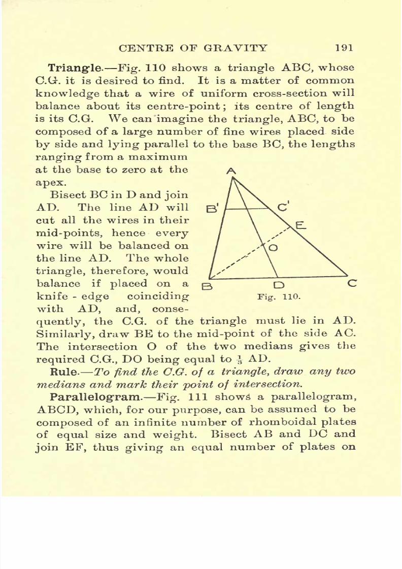
7/29/2019 Elementary Graphi 00wighrich
http://slidepdf.com/reader/full/elementary-graphi-00wighrich 207/256
CENTRE OF GRAVITY 191
Triangle. Fig. 110 shows a triangle ABC, whose
C.O. it is desired to find. It is a matter of common
knowledge that a wire of uniform cross-section will
balance about its centre-point; its centre of length
is its C.G. We can imagine the triangle, ABC, to be
composed of a large number of fine wires placed side
by side and lying parallel to the base BC, the lengths
ranging from a maximum
at the base to zero at the
apex.
Bisect BC in D and join
AD. The line AD will
cut all the wires in their
mid-points, hence every
wire will be balanced on
the line AD. The whole
triangle, therefore, would
balance if placed on a
knife -edge coinciding
with AD, and, conse-
quently, the C.G. of the triangle must lie in AD.
Similarly, draw BE to the mid-point of the side AC.
The intersection O of the two medians gives the
required C.G., DO being equal to-|-AD.
Rule- To find the C.G. of a triangle, draw any two
medians and mark their point of intersection.
Parallelogram. Fig. Ill shows a parallelogram,
ABCD, which, for our purpose, can be assumed to be
composed of an infinite number of rhomboidal plates
of equal size and weight. Bisect AB and DC and
join EF, thus giving an equal number of plates on

7/29/2019 Elementary Graphi 00wighrich
http://slidepdf.com/reader/full/elementary-graphi-00wighrich 208/256
192 ELEMENTARY GRAPHIC STATICS
each side of the line EF. Consider
anytwo small
plates, in the same horizontal row, equidistant from
EF. Since these are of equal weight and equidistant
from EF, their moments about EF will be equal and
opposite, hence balance will be obtained. Everyindividual plate to the right of EF has a correspond-
ing partner to the left of EF, hence all the
plates
on
the one side will balance all the plates on the other.
The C.G. of the parallelogram therefore lies on the
line EF. In a similar way the C.G. must lie on the
line GH. Hence the
A E B intersection is the'
I I I I I I I I I I I I l~l reouired C G It will
///_///////-// // required
<^AT. it wn
I M I H Ibe seen that the P int
//////9///////His also the inter-
////// section of the dia-'II iIn gonals.
^Illlinil/Jin RuleTo find the
Fjgt
lllaC.G. of a parallelo-
gram, draw the two
diagonals and mark their intersection.
Many simple geometrical figures can readily be
subdivided into triangles and parallelograms, and the
two preceding solutions readily suggest a means of
solution. It will be sufficient, in this connection, to
consider only one case. In Fig. 112 is shown a
steel plate of the given shape, ABCD, and it is
required to find the position of a hole, from which,
if the plate be suspended by a cord, it will remain in
a horizontal position. Draw BE parallel to AD, and
AFparallel
to BC. Find the C.G. of thetriangle

7/29/2019 Elementary Graphi 00wighrich
http://slidepdf.com/reader/full/elementary-graphi-00wighrich 209/256
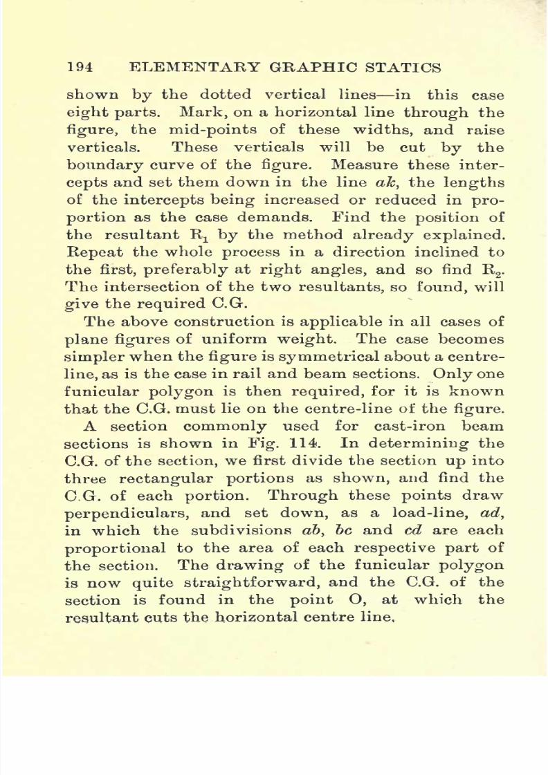
7/29/2019 Elementary Graphi 00wighrich
http://slidepdf.com/reader/full/elementary-graphi-00wighrich 210/256

7/29/2019 Elementary Graphi 00wighrich
http://slidepdf.com/reader/full/elementary-graphi-00wighrich 211/256
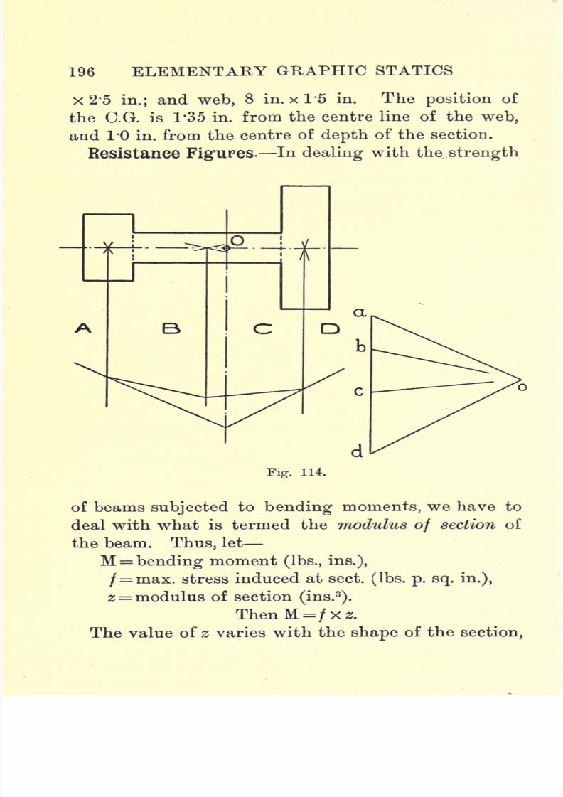
7/29/2019 Elementary Graphi 00wighrich
http://slidepdf.com/reader/full/elementary-graphi-00wighrich 212/256

7/29/2019 Elementary Graphi 00wighrich
http://slidepdf.com/reader/full/elementary-graphi-00wighrich 213/256
CENTRE OF GRAVITY 197
and, in determining its value for a given section, we
can make use of certain simple graphical construc-
tions. Consider the section, ABCD, as shown in Fig.
117, and let us assume that the maximum stress in-
duced in a layer, at a distance y from the N.A, is / Ibs.
per sq. in. At any distance y' the stress induced will
be less and willbe equal
to/ X
^- . This is the stress
y
intensity which is acting on the cross-sectioned strip,
Fig. 115.
whose area we can take as a square inches. Now,
obviously, if we reduce this area a, we will increase
the stress per sq. in., since the total stress(/X x a
J
*j
will now be distributed over a smaller area. Keepingthe depth of the strip the same, let us reduce its
width until the area is a' and the stress intensity /
Ibs. per sq. in., then we have
y
a y
Therefore, to give uniformity of stress over the whole

7/29/2019 Elementary Graphi 00wighrich
http://slidepdf.com/reader/full/elementary-graphi-00wighrich 214/256
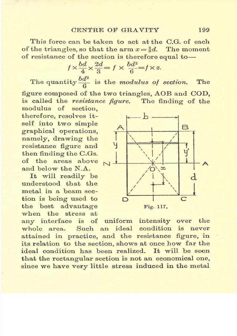
7/29/2019 Elementary Graphi 00wighrich
http://slidepdf.com/reader/full/elementary-graphi-00wighrich 215/256
CENTRE OF GRAVITY 199
This force can be taken to act at the C.G. of each
of the triangles, so that the arm x = ^d. The moment
of resistance of the section is therefore equal to
, bd 2d_, U\' T x y~' ^
The quantity - is the modulus of section. The
figure composed of the two triangles, AOB and COD,is called the resistance figure. The finding of the
modulus of section,
therefore, resolves it-
self into two simple
graphical operations,
namely, drawing the
resistance figure and
then finding the C.Gs.
of the areas above
and below the N.A.
It will readily be
understood that the
metal in a beam sec-
tion is being used to
the best advantage
when the stress at
any interface is of uniform intensity over the
whole area. Such an ideal condition is never
attained in practice, and the resistance figure, in
its relation to the section, shows at once how far the
ideal condition has been realized. It will be seen
that the rectangular section is not an economical one,
since we have very little stress induced in the metal
Fig. 117.
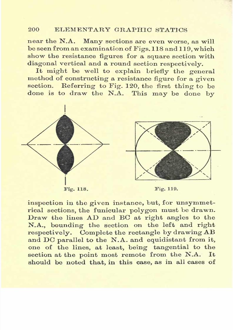
7/29/2019 Elementary Graphi 00wighrich
http://slidepdf.com/reader/full/elementary-graphi-00wighrich 216/256
200 ELEMENTARY GRAPHIC STATICS
near the N.A.
Manysections are even
worse,as will
be seen from an examination of Figs. 118 and 119, which
show the resistance figures for a square section with
diagonal vertical and a round section respectively.
It might be well to explain briefly the general
method of constructing a resistance figure for a given
section.
Referringto
Fig. 120,the first
thingto
bedone is to draw the N.A. This may be done by
Fig. 118. Fig. 119.
inspection in the given instance, but, for unsymmet-
rical sections, the funicular polygon must be drawn.
Draw the Hues AD and BC at right angles to the
N.A., bounding the section on the left and right
respectively. Complete the rectangle by drawing AB
and DC parallel to the N.A. and equidistant from it,
one of the lines, at least, being tangential to the
section at the point most remote from the N.A. It
should be noted that, in this case, as in all cases of

7/29/2019 Elementary Graphi 00wighrich
http://slidepdf.com/reader/full/elementary-graphi-00wighrich 217/256

7/29/2019 Elementary Graphi 00wighrich
http://slidepdf.com/reader/full/elementary-graphi-00wighrich 218/256
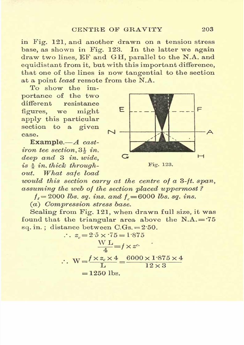
7/29/2019 Elementary Graphi 00wighrich
http://slidepdf.com/reader/full/elementary-graphi-00wighrich 219/256
CENTRE OF GRAVITY 203
in Fig. 121, and another drawn on a tension stress
base, as shown in Fig. 123. In the latter we again
draw two lines, EF and GH, parallel to the N.A. and
equidistant from it, but with this important difference,
that one of the lines is now tangential to the section
at a point least remote from the N.A.
To show the im-
portance of the two
different resistance
figures, we might
apply this particular
section to a given
case.
Example. A cast-
iron tee section, 3 in.
deep and 3 in. wide,
is f in. thick through-
out. What safe load
would this section carry at the centre of a 3-ft. span,
assuming the web of the section placed uppermost ?
/,= 2000 Ibs. sq. ins. and /c=6000 Ibs. sq. ins.
(a) Compression stress base.
Scaling from Fig. 121, when drawn full size, it was
found that the triangular area above the N.A.= *75
sq. in.;distance between C.Gs. = 2*50.
.'. z = 2-5 x '75 =1/875
Fig. 123.
4
w _/xzg x4_ 6000 x 1 '875 x 4
= 1250 Ibs.
12x3

7/29/2019 Elementary Graphi 00wighrich
http://slidepdf.com/reader/full/elementary-graphi-00wighrich 220/256
204 ELEMENTARY GRAPHIC STATICS
Therefore, as far as the
compressionstress is
concerned, we could safely load the beam to
1250 Ibs.
(b) Tension stress base.
Scaling from Fig. 123, when drawn full size, it was
found that the triangular area above the N.A. = 1*5
sq.
ins.
.'. s,=2-5x T5 = 3-75,
WL ,
=/xz,.
w= /xz;X4_2000x 3-75x4
L 12x3
= 830 Ibs.
Therefore, safe load is 830 Ibs. at centre, this being
the load which induces the maximum tension stress
allowable.
It should be noted that a well-designed section in
cast-iron will have the maximumcompression
and
tension stresses acting simultaneously.
From an examination of Fig. 123, it will be seen
that, at the outside layers of the web, the width of
strip necessary to keep the stress down to a given
limit is wider than the section at that point can
provide,and it would therefore
appearthat the section
will be overstressed at that point. It must be borne
in mind, however, that the stress at this point is a
compression, whose limiting value is very much higher
than the limiting value in tension.
Fig. 124 shows the resistance figure for a rail sec-
tion. The area of one-half of the resistancefigure
is
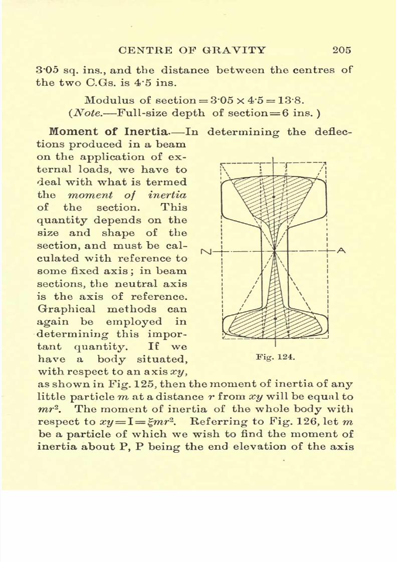
7/29/2019 Elementary Graphi 00wighrich
http://slidepdf.com/reader/full/elementary-graphi-00wighrich 221/256
CENTRE OF GRAVITY 205
3*05sq. ins.,
and the distance between the centres of
the two C.Gs. is 4*5 ins.
Modulus of section= 3'05 x 4'5 = 13'8.
(Note. Full-size depth of section= 6 ins.)
Moment of Inertia In determining the deflec-
tions produced in a beam
on the application of ex-
ternal loads, we have to
deal with what is termed
the moment of inertia
of the section. This
quantity depends on the
size and shape of the
section, and must be cal-
culated with reference to
some fixed axis;in beam
sections, the neutral axis
is the axis of reference.
Graphical methods can
again be employed in
determining this impor-
tant quantity. If we
have a body situated,FlS- 124-
with respect to an axis xy,
as shown in Fig. 125, then the moment of inertia of any
little particlem at a distance r from xy will be equal to
mr2. The moment of inertia of the whole body with
respect to xy=I= %mr2
. Referring to Fig. 126, let mbe a particle of which we wish to find the moment of
inertia about P, P being the end elevation of the axis

7/29/2019 Elementary Graphi 00wighrich
http://slidepdf.com/reader/full/elementary-graphi-00wighrich 222/256
206 ELEMENTARY GRAPHIC STATICS
of reference. Set down ab to
representm, select a
pole o, preferably making H an even number of ins.
Join oa and ob and draw me and md parallel to oa
and ob respectively. Then, as explained in Chapter
IV., we have abxr=cdxH', (abxr) is thefirst
moment of m about P.
Now set down cd and select a pole o', making, if
Fig. 125.
possible,H1
equal to H. From o" draw o"e and o"/
parallel to o'c, and o'd respectively.
Then again we have ef X H1
= cd x r.
abxrBut cd=
H
.. .
H.-. ef x H 1 x H = ab x r x r
The quantity (ab x r2)
is termed the second moment
of m about P, or the moment of inertia of m about P.
If the above diagrams are drawn so that 1 in. = 1 lb.,
and so that r is full size, then there will be no diffi-
culty
in finding the value of IP, but, in general, both
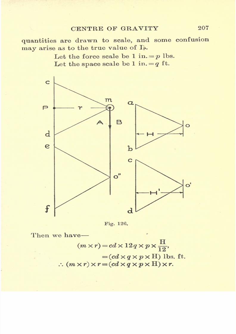
7/29/2019 Elementary Graphi 00wighrich
http://slidepdf.com/reader/full/elementary-graphi-00wighrich 223/256
CENTRE OF GRAVITY 207
quantities are drawn to scale, and some confusion
may arise as to the true value of IP.
Let the force scale be 1 iu. = p Ibs.
Let the space scale be 1 ir\. = q ft.
f
m
Fig. 126.
Then we have
H
(cd x q x p x H) Ibs. ft.
7/29/2019 Elementary Graphi 00wighrich
http://slidepdf.com/reader/full/elementary-graphi-00wighrich 224/256
208 ELEMENTARY GRAPHIC STATICS
Nowfrom the
diagramit will be
seenthat
rfl.1
vr0.)-ef r
TT. mr2 = efx x #
2 x p x H x r,r
=(e/ x g
2 X p) X Hxx H Ibs. ft.
2units.
Thus let m equal 15 Ibs. and r equal 12 ft. The
scales used in the original diagram are 1 in. equals
10 Ibs., and 1 in. equals 8 ft., and e/= 2'15 ins.
.*. IP
'
= ef x q2 x p x H-L x H,
= 215 x 82 x 10 x 1-25 x ^(H^ = H = 1-25 in.),
= 2144 Ibs. ft.2
units,
rar2= 15x12x12,= 2160 Ibs. ft.
2 units.
Moment of Inertia of a System of Forces. Theabove construction can readily be applied to deter-
mine the moment of inertia of a system of forces, such
as are shown in Fig. 127, but it will be seen that
the moment of inertia, so found, does not equal the
moment of inertia of the beam section (shown dotted)
from which these individual forces have been derived.A close approximation can, however, be obtained, by
dividing the section into a large number of strips,
whose axes are parallel to the N.A. The section in
this case is of cast-iron, the compression flange being
8 ins. x 4 ins.=32 sq. ins., the tension flange 6 ins. x 2
ins.= 12 sq. ins., and the web 12 ins.x2 ins.
=24 sq. ins,
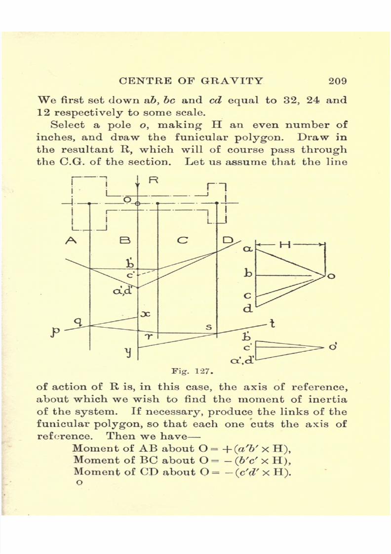
7/29/2019 Elementary Graphi 00wighrich
http://slidepdf.com/reader/full/elementary-graphi-00wighrich 225/256
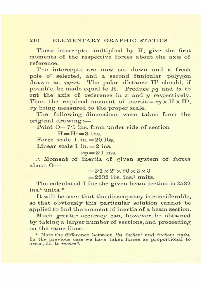
7/29/2019 Elementary Graphi 00wighrich
http://slidepdf.com/reader/full/elementary-graphi-00wighrich 226/256
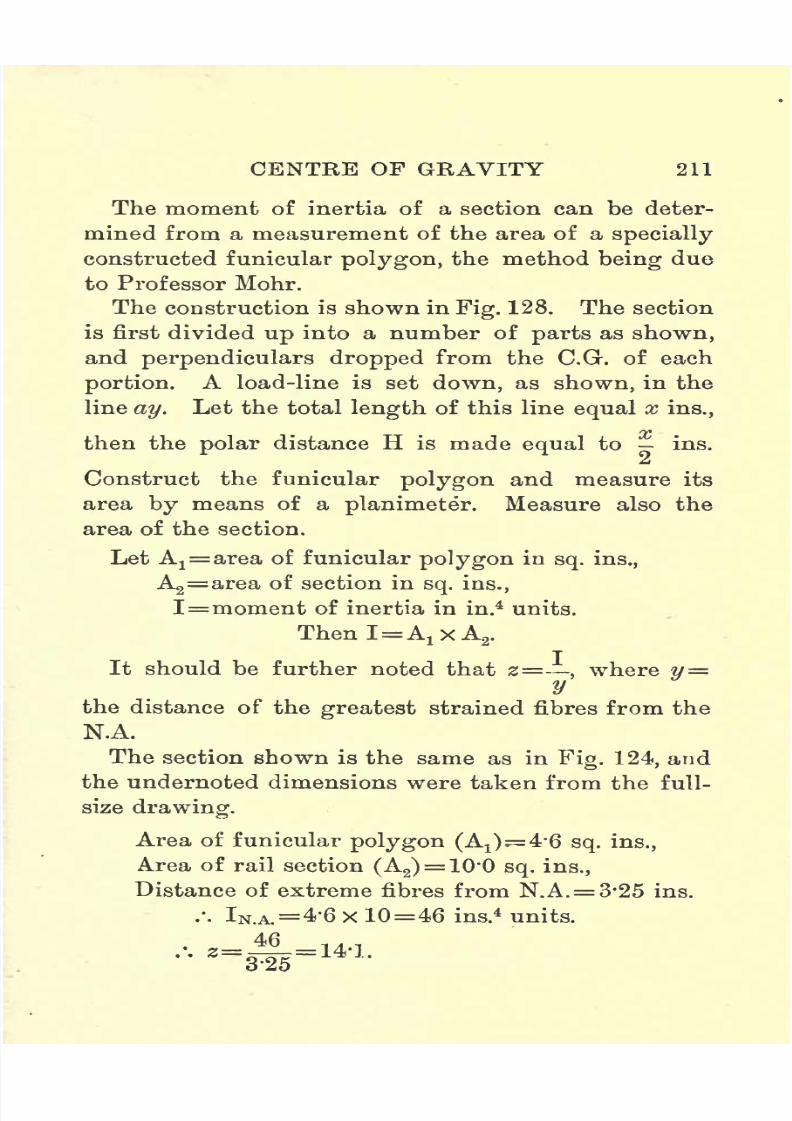
7/29/2019 Elementary Graphi 00wighrich
http://slidepdf.com/reader/full/elementary-graphi-00wighrich 227/256
CENTRE OF GRAVITY 211
The moment of inertia of a section can be deter-mined from a measurement of the area of a specially
constructed funicular polygon, the method being due
to Professor Mohr.
The construction is shown in Fig. 128. The section
is first divided up into a number of parts as shown,
andperpendiculars dropped
from theC.G.
of each
portion. A load-line is set down, as shown, in the
line ay. Let the total length of this line equal x ins.,
then the polar distance H is made equal to ins.
t
Construct the funicular polygon and measure its
area by means of a planimeter. Measure also the
area of the section.
Let Ax=area of funicular polygon in
sq. ins.,
A2=area of section in
sq. ins.,
I=moment of inertia in in.4units.
ThenI=A1xA
2.
It should be further noted that z= . where 11=y
the distance of the greatest strained fibres from the
N.A.
The section shown is the same as in Fig. 124, and
the undernoted dimensions were taken from the full-
size
drawing.Area of funicular polygon (Ax )
4*6 sq. ins.,
Area of rail section (A2)= 10'0 sq. ins.,
Distance of extreme fibres from N. A.= 3-25 ins.
.-. IN A =4-6 x 10=46 ins.4units.
--'.
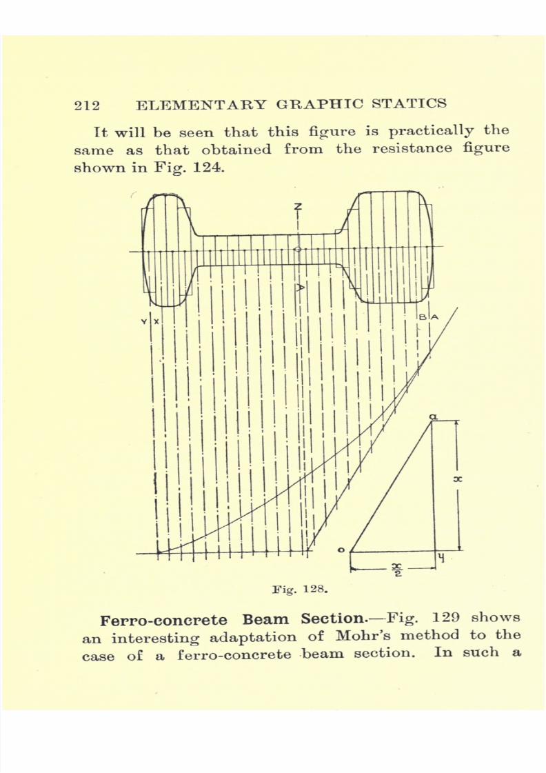
7/29/2019 Elementary Graphi 00wighrich
http://slidepdf.com/reader/full/elementary-graphi-00wighrich 228/256
212 ELEMENTARY GRAPHIC STATICS
It will be seen that thisfigure
is
practically
the
same as that obtained from the resistance figure
shown in Fig. 124
Fig. 128.
Ferro-eonerete Beam Section. Fig. 129 shows
an interesting adaptation of Mohr's method to the
case of a ferro-concretebeam section. In such a
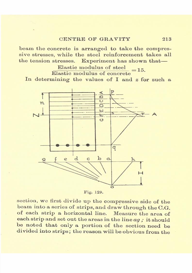
7/29/2019 Elementary Graphi 00wighrich
http://slidepdf.com/reader/full/elementary-graphi-00wighrich 229/256
7/29/2019 Elementary Graphi 00wighrich
http://slidepdf.com/reader/full/elementary-graphi-00wighrich 230/256
214 ELEMENTARY GRAPHIC STATICS
diagram. Througha raise a vertical and mark off
oa= H, making this preferably an even number of ins.
Measure the area of the steel reinforcing bars.
Let m = number of steel bars,
a' area of each bar insq. ins.
Then total area= (m x a') sq. ins.
Set off ah=(\5xmxa') sq. ins., being
careful to
set ah off to the same scale as was used for ag. Join
the various points to the pole o, and construct the
funicular polygon pqr as shown. The horizontal
through r will give the N.A. of the section.
Then I (for section about N.A.)=area pqr x 2H.
In general, the sectionwill be
drawnto
some scale,
and this must be borne in mind when measuring the
area pqr. The area pqr is measured to the scale to
which the section has been drawn, and H is measured
to the scale to which ab, be, etc., have been set out.
Thus if the beam section be drawn half size, the
area of the section andalso of the
funicular polygonwill only be one quarter of its full-size value, and if
ah be drawn to a reduced scale, then obviously the
length sr will be reduced in the same proportion.
Now I (for steel)=
(15 x steel area) x sq2
= ahx sq2
.
-r,,
sr ah ahBut _= = -=-.
sq ao HsrxH , , srxH
/ . sq= = and ah =-h sq
= 2 x area qsrxTL.
. . I(steel)
= areaqsr
x 2H.

7/29/2019 Elementary Graphi 00wighrich
http://slidepdf.com/reader/full/elementary-graphi-00wighrich 231/256
CENTRE OF GRAVITY 215
Similarly I (total)= area pqr x 2H.
Now, let k= number of reductions of section,
m = scale of load-line ag,
A3= actual area of pqr in sq. ins.
Then I (total)= (A3
x &2 x m) x 2H,
= (A3x k2
) x (2H x m) in.4 units.
The undernoted dimensions were taken from the
original drawing of Fig. 129 :
Area of pqr (A3)= 08
sq. in.
Area of qsr =0*54 sq.in.
Scale of section, 1J ins. = 1 ft. . . k = S.
Scale of load line 1 in. =48 sq. ins. .*. m = 48.
Polar distance H = 1 in.
Area of steel x 15 = 2'2 x 15 = 33.
Distance sq= W'l ins. (full size).
. . I (total)=
(0-8 x 82
) x (2 x 1 X 48),
= 0-8x64x96,= 4915 in.
4 units.
Again, checking for steel only
I (steel)= area srq x &2 x 2H x m= 0-54 x 64 x 2 x 48 = 3320 in.
4 units.
andmr2=(2-2xl5)xl01
2
= 33x102
= 3366 in.4 units.
The slight difference can be accounted for by errors
in drawing, especially when the scale of the original
drawing is one-eighth full size.
It is now a simple matter to determine the modulus
of section.

7/29/2019 Elementary Graphi 00wighrich
http://slidepdf.com/reader/full/elementary-graphi-00wighrich 232/256
216 ELEMENTARY GRAPHIC STATICS
Let fc=crushing strength
of concrete in Ibs.
p. sq.
in.
n = distance of greatest strained particles from
N.A. in ins.
Then z=T (total)
,and the mom. of resist. = !**!
n n
Examples.
1. Drawany irregular figure,
such as is shown in
Fig. 113. Find, by the funicular polygon method,
the C.G. of the area.
Carefully cut out the figure and check your result
by the suspension method.
2. A steel plate is composed of two circular discs,
joined together bya
rectangular piece,whose centre
line passes through the centre of each circle. One
circle is 3 ft. diam. and the other is 2*25 ft. diam.
The distance from centre to centre of the circles is
4*5 ft. and the rectangular piece is 1'2 ft. wide. Find
the C.G. of the piece.
3. Arectangular
beam is 6 ins.
deep by3 ins. wide.
Draw the resistance figure and find the modulus of
section. Check your result by calculation and find
the safe distributed load on a 4-ft. span if the stress
is not to exceed 2500 Ibs. per sq. in.
4. Draw the resistance figures for
(a)
Asquare,
4 ins. side, withdiagonal
vertical,
(b) A circular section, 4'5 ins. diam. (solid),
(c) A hollow circular section,8 ins.O.D.and 4 ins.I.D.,
(d) A tee section, 1 in. metal throughout, 6 ins.
deep and 4 ins. wide, on both bases.
5. A cast-iron beam section is 18 ins. deep. The
tensionflange
is 8 ins. X 3 ins.;the
compression flange
7/29/2019 Elementary Graphi 00wighrich
http://slidepdf.com/reader/full/elementary-graphi-00wighrich 233/256
CENTRE OF GRAVITY 217
6 ins. X If in.; and the web 1-| in. thick. Find the
C.G. Draw the resistance figure and find the modulus
of section.
Calculate the safe distributed load for an 8-ft. span
if the stress in tension is not to exceed 2000 Ibs. per
sq.in.
6. Draw a horizontal line AB, 8 ins. long. Apply
forces, P, Q and S, 3 ins., 5 ins., and 8 ins. from A
respectively. Find the moment of inertia of the
system about the point A when the forces have the
following values :
P+ 8 lbs. + 6 +8,
Q+ 6 -10-7,
S+ 10 +11-10.
7. Draw out the rail section shown in Fig. 124 to such
a scale that its depth is 8 ins. Find its C.G. Draw
the resistance figure and find its modulus of section.
8. Using the section of Question 7, find, by Mohr's
method, the moment of inertia of the section, and
check your value of z found from the previous
question.
9. A reinforced concrete beam is 18 ins. wide and
24 ins. deep to the centre of the reinforcement, which
consists of 6 bars, 1 in. diam. Find
(a) Position of N.A.,
(6) Value of I (total),
(c) Value of z.
Assuming a beam of this section simply supported at
the ends, find the maximum safe span for a dis-
tributed load of 1 ton per foot-run, if fc must not
exceed 600 Ibs. per sq. in.

7/29/2019 Elementary Graphi 00wighrich
http://slidepdf.com/reader/full/elementary-graphi-00wighrich 234/256
CHAPTER XII
RETAINING WALLS
A RETAINING wall, generally of masonry, is the
name given to such structures as are employed
to sustain earth or water pressure, although the
expression is used more particularly in connection
with earthworks, while in waterworks the termdam is more commonly used. The forces acting on
retaining walls and the nature of the stresses in-
duced are quantities which, at the present time, are
still the subject of much discussion and difference
of opinion. The whole subject is a wide and very
complicated one, and only problems of a very elemen-
tary nature can be treated here.
The most straightforward case with which we
have to deal is the retaining wall or dam as used to
sustain a water pressure. The arrangement is shown,
in its crudest form, in Fig. 130. Obviously the water
must exert a pressure, such as P, on the back of the
wall, and our knowledge of hydrostatics teaches us
that P must act normally to the wall, on the inner
face. It will readily be seen that the force, P, will
tend to overturn the wall about the point O, the
magnitude of the overturning moment being equal to
P X H. Now, the weight of the wall, W, acting at a218

7/29/2019 Elementary Graphi 00wighrich
http://slidepdf.com/reader/full/elementary-graphi-00wighrich 235/256
RETAINING WALLS 219
distance H1 from O, tends to
keepthe wall
steady byresisting the overturning moment. The condition of
balance is obtained when PxH just equals W x H1
,
and the wall would then just be on the point of over-
turning. In practice, however, this point must never
be reached, and, to ensure stability and certain other
conditions regarding the stresses at the joints, it
becomes necessary to im-
pose certain restrictions.
If we combine the two
forces P and W and find
their resultant, then the
relationship between P
and W must be such
that the line of action
of the resultant must cut
the base within the middle
third of its width.
Referring to Fig. 131,
let ABCD represent a
cross-section of the dam.
It should be noted that, in working out problems
on retaining walls, we always deal with 1-ft. length
of the wall. In this case let
A= cross-sectional area of wall in sq. ft.,
w= weight of material of wall in Ibs. per cubic ft.,
h= depth of water in reservoir in ft.
Then W=Axlxw.= A.W Ibs. acting at the C.G. of the section.
As shown by the triangle GHC, the pressure

7/29/2019 Elementary Graphi 00wighrich
http://slidepdf.com/reader/full/elementary-graphi-00wighrich 236/256
220 ELEMENTARY GRAPHIC STATICS
exerted
bythe water on the wall
gradually increases,from zero at the surface to a maximum at the bottom.
.-. p= fc xlx|
X62-4.
= 31'2^2lbs.
This total pressure acts at a point K, where CK=JX C.G. With the aid of the
parallelogramof
forces,find the resultant R
of P and W.
Trisect the base
DC in E and F, and
all the necessary con-
ditions ofstability
will be fulfilled if
the line of action of
the resultant (R) cuts
the middle third (EF)
of the base.
It
should, however,be noted that manycases occur in practice
where the resultant
falls outside the
middle third, so that
the above rule,
although givingideal
conditions,is
not of universal application.
Example. A masonry dam, 8ft. high, is 5
ft. wide
at the base and 1ft. 8 ins. wide at the top, while
the outer face has a batter of 1 in 8. Under certain
conditions the water rises to the top of the wall.
Determinegraphically
if the wall is
safe
under these
H
Fig. 131.
7/29/2019 Elementary Graphi 00wighrich
http://slidepdf.com/reader/full/elementary-graphi-00wighrich 237/256
RETAINING WALLS 221
conditions. Take the weight of masonry as 150 Ibs.
per cubic ft.
= 1995 Ibs.
Note that this force acts normally to the inner
face AB.
8x150,
= 3-33x1200,
= 4000 Ibs.
Find the C.G. of the wall section in the point O,
and, through O, draw a vertical to represent W.
Produce the line of action of P to intersect 06 in a.
Mark off ac equal to 1995 Ibs., to scale, and ab equal
to 4000 Ibs. Complete the parallelogram and join
ad. It will be seen that R cuts the base outside the
middle third, so that the wall may probably not be
safe.
The solution of problems dealing with the stability of
retaining walls for earth pressure presents more diffi-
culties than the preceding case, chiefly on account of
the uncertainty of the magnitude of the thrust which
the earth exerts on the back of the wall. Fig. 133
shows a section of a retaining wall,the earth being level
on the top and flush with the top of the wall. Earth,
like other materials of a similar nature, will be found
to assume a certain definite slope when tipped on to
a level plane, such as C.G. The slope assumed is
shown by the line CE, and the inclination of the line,
measured by the angle <p,is termed the natural slope,
while the angle <pis termed the angle of repose,
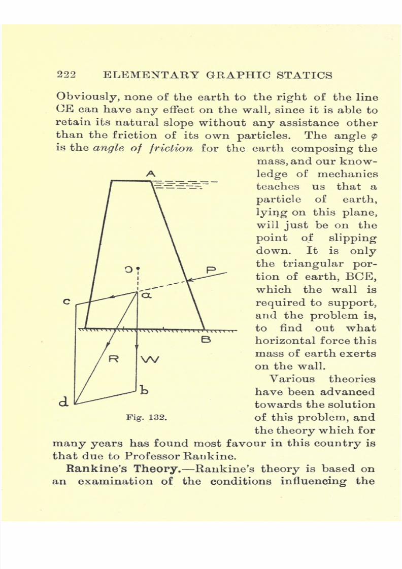
7/29/2019 Elementary Graphi 00wighrich
http://slidepdf.com/reader/full/elementary-graphi-00wighrich 238/256
222 ELEMENTARY GRAPHIC STATICS
Obviously, none of the earth to the right of the lineCE can have any effect on the wall, since it is able to
retain its natural slope without any assistance other
than the friction of its own particles. The angle p
is the angle of friction for the earth composing the
mass, and our know-
A ledge of mechanicsteaches us that a
particle of earth,
lying on this plane,
will just be on the
point of slipping
down. Itis
onlythe triangular por-
tion of earth, BCE,
which the wall is
required to support,
and the problem is,
to find out whathorizontal force this
mass of earth exerts
on the wall.
Various theories
have been advanced
towards the solutionof this problem, and
the theory which for
many years has found most favour in this country is
that due to Professor Raukine.
Rankine's Theory. Raukine's theory is based on
an examination of the conditions influencing the
Fig. 132.

7/29/2019 Elementary Graphi 00wighrich
http://slidepdf.com/reader/full/elementary-graphi-00wighrich 239/256
RETAINING WALLS 223
equilibriumof the individual
particlesof earth form-
ing the mass. When the earth surface is level and
the back of the wall perpendicular, Rankine states
Fig.
133.
that the horizontal pressure can be determined from
the following formula :
Let P = horizontal force acting on the wall per ft.
of length in Ibs.,
Ji
height
of wall in ft.,
w= weight of earth in Ibs. per cubic ft.,
<p=angle of repose.
\l-t-sin
This force acts horizontally on the wall at point
\h up from the base. It is a well-known fact that
this formula gives values of P much in excess of the
actual values existing. The difference in many cases
amounts to as much as 30 per cent.; it, however,
errs on the side of safety, which is a distinct advan-
tage, considering the uncertainty of the problem.
Coulomb's Theory. This theory is based on the

7/29/2019 Elementary Graphi 00wighrich
http://slidepdf.com/reader/full/elementary-graphi-00wighrich 240/256
224 ELEMENTARY GRAPHIC STATICS
fact that the earthlying
above the naturalslope, i.e.,
the triangular portion BCE (Fig. 133), will tend to
slide down the plane and so tend to overturn the
wall. It has been shown, however, that the over-
turning effect of the portion BCE is much less than
that due to the smaller triangular portion BCF, and,
infact,
that the maximumoverturning
moment is
obtained when BCF tends to slide down a plane CF.
which is so situated that CF bisects the angle BCE.
This plane is known as the plane of rupture. To
show the application of this method, we will now
consider a simple example.
Example. A retaining wall,14
ft. high,is 5
ft.
wide at the base and 2ft.
wide at the top, the back of
the wall being perpendicular. This wall is required
to sustain the pressure of a bank of damp clay which
is flush with the top of the wall. Determine whether
the conditions of stability are fulfilled if the angle of
reposeis 45.
Damp clay weighs120 Ibs.
percubic
ft.and masonry 170 Ibs. per cubic
ft.
Fig. 134 shows the arrangement, the angle BDK
being equal to 45. Draw DE, the bisector of BDK,
and find the C.G. of the triangle BDE,inthe point 0'.
The length BE will be found to measure approxi-
mately5 '75 ft.
Hence, callingW 1 the
weightof the
prism, whose section is BDE, we have W1= (|x5*75
X 14 X 120) Ibs. = 4825 Ibs. Now, find the C.G. of the
wall section, ABDC, in the point O, and calculate the
weight, W, of 1 ft. length of the wall, thus
W = ^} x 14 x 1 70 = 8330 Ibs,
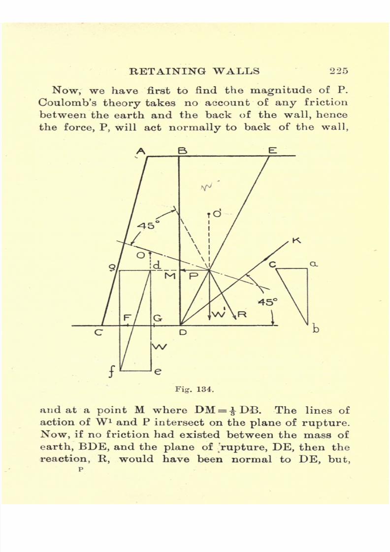
7/29/2019 Elementary Graphi 00wighrich
http://slidepdf.com/reader/full/elementary-graphi-00wighrich 241/256
RETAINING WALLS 225
Now, we have first to find the
magnitude
of P.
Coulomb's theory takes no account of any friction
between the earth and the back of the wall, hence
the force, P, will act normally to back of the wall,
and at a point M where DM = DB. The lines of
action of W1 and P intersect on the plane of rupture.
Now, if no friction had existed between the mass of
earth, BDE, and the plane of jrupture, DE, then the
reaction, R, would have been normal to DE, but,

7/29/2019 Elementary Graphi 00wighrich
http://slidepdf.com/reader/full/elementary-graphi-00wighrich 242/256
226 ELEMENTARY GRAPHIC STATICS
since the angle of friction is 45, we can obtain R's
Hue of action by drawing a line making an angle of
45 with the normal to the plane, as shown. The
three forces, W 1
, R, and P, are in equilibrium, hence
we can determine their individual values by drawingthe triangle of forces abc. Draw a vertical through
to represent the line of action of W, and produce
Fig. 135.
the line of action of P to cut it in d. Mark off dg =
ac and de= W, and complete the parallelogram. The
resultant will be found to cut the base within the
middle third, FG, hence the conditions of stability
are fulfilled. For more exact methods, makingallowance for earth friction at the back of the wall,
the student is advised to consult the various text-
books on this subject.
Rebhann's Method. It might be advantageous to
7/29/2019 Elementary Graphi 00wighrich
http://slidepdf.com/reader/full/elementary-graphi-00wighrich 243/256
RETAINING WALLS 227
indicate onegraphical
construction which has been
used for many years by Continental engineers.
Rebhann's construction is based on Coulomb's theory,
and seems to give results which are quite satisfactory
and in agreement with actual practice. Fig. 135
shows a section of a retaining wall, AC being the
level of the earth, which, in this case, rises to a point
higher than the top of the wall. The natural slope
is indicated by the line BC, on which line describe
a semicircle, EEC. At A construct an angle BAD
equal to 2p, and from D draw DE at right angles to
BC. With centre B and radius BE, cut BC in F, and
draw FG parallel to AD. Make FK equal to FG and
join GK. Then the triangle FGK is termed the
earth pressure triangle.
Let A=area of FGK in sq. ft.,
w= weight of earth in Ibs. per cubic ft.,
P = resultant pressure on wall in Ibs. per ft.
of length.
Then P = (Axlxw) Ibs.
Mark off BL equal to BA, and through L draw
the line of action of P parallel to the natural slope.
P and W may now be combined in the usual waywith the aid of the parallelogram of -forces. P can
be split up into its horizontal and vertical com-
ponents, as shown in the force triangle above.

7/29/2019 Elementary Graphi 00wighrich
http://slidepdf.com/reader/full/elementary-graphi-00wighrich 244/256
EDINBURGH
COLSTONS LIMITED
PRINTERS

7/29/2019 Elementary Graphi 00wighrich
http://slidepdf.com/reader/full/elementary-graphi-00wighrich 245/256
A LIST OF BOOKS PUBLISHED BYWHITTAKER & CO.,
2, White Hart St., Paternoster Square, London, E.G.
A complete Catalogue giving full details of the following
books will be sent post free on application. : : :
s. d.
ADAMS, H. Practical Trigonometry, for the use of
Engineers, Surveyers, &c. ... ... net 2 6'
ALEXANDER, J. Model Engine Construction net 5
ALLSOP, F. C. Practical Electric Light Fitting net 4 6
ANDERSON, Sir W. Conversion of Heat intoWork net 5
ARNOLD, J. O., and IBBOTSON, F. Steel Work
Analysis ... ... ... ... net 10 6
ASHWORTH, J. R. Magnetism and Electricity net 2
Heat, Light and Sound, Practical
Exercises in ... ... ... net 2
ATKINS,E. A. Practical Sheet and Plate Metal
Work ... ... ... ... net 6
BAMFORD, H. Moving Loads on Railway Under
bridges ... ... ... ... net 4 6
BARR, J. R. Direct Current Electrical Engineering net 10
BARR, J. R. and ARCHIBALD, R. D. Design of
Alternating Current Machinery ... net 12 6
BARTER, S. Manual Instruction Woodwork net 6
,, Manual Instruction Drawing net 3 6
BEAUMONT, R. Colour in Woven Design, a Treatise
on Textile Colouring... ... ... net 18
BJORLING, P. R.. Pipes and Tubes, their Construe
tion and Jointing ... ... ... net 3 6
2, White Hart Street, Paternoster Square, E.C,

7/29/2019 Elementary Graphi 00wighrich
http://slidepdf.com/reader/full/elementary-graphi-00wighrich 246/256
Published by WHITTAKER & CO.,
BLAKESLEY,T. H.
AlternatingCurrents of Elec-
tricity ... ... ... ... net 5
BLAKESLEY, T. H. Geometrical Optics ... net 2 6
BODMER, G. R. Hydraulic Motors and Turbines net 12 6
Inspection of Railway Material net 4 6
BONNEY, G.-E. Electro Plater's Handbook net 2 6
,, Electrical Experiments ... net 2 6
Induction Coils ... net 3
BOTTONE, S. R. Guide to Electric Lighting net 1
,,How to manage the Dynamo net 9
,,Wireless Telegraphy and Hertzian
Waves ... ..."net 2 6
Electrical Instrument Making forAmateurs ... net 3
,,Electric Motors, how made and
how used ... net 2 6
Electricity and Magnetism net 2 6
,, Electric Bells and all about them net 2
,, Radiography, its Theory, Practice
and Applications ... net 3 6
Galvanic Batteries, their Theory,Construction and Use net 4 6
,,Radium and all about it ... net 1
BOYD, R. N. Petroleum, its Development and
Uses ... ... net 2
BRODIE, C. G. Dissections Illustrated ... net 15
BROWNE, A. J. JUKES. Elementary Geology net 2 6
BURNS, D., and KERR, G. L, Modern Practice of
Coal Mining. Parts ... ... each net 2
CHAMBERS, G. E. Astronomy, for General Readers net 1
COOKE, C. J. B. British Locomotives ... net 6
2, White Hart Street, Paternoster Sauare. E.G.

7/29/2019 Elementary Graphi 00wighrich
http://slidepdf.com/reader/full/elementary-graphi-00wighrich 247/256
Published by WHITTAKER & CO.,
s. d.
COPPOCK, J. B. Volumetric Analysis ... net 2
CULLYER, J. Tables for Measuring and ManuringLand ... ... ... ... net 2 6
DAVIS, W. E. Quantities and Quantity Taking net 3 6
DENNING, D. Art and Craft of Cabinet Making net 4 6
EDGCUMBE, K. Electrical Engineers' Pocket Book net 5
ELLIOTT, A. G. Gas and Petroleum Engines net 2 6
ELSDEN and GREENWELL. Roads, their Con-
struction and Maintenance ... ... net 5
Engineer Draughtsmen's Work. Hints to Beginners
in Drawing Offices ... ... net I 6
Explosives Industry, Riseand Progress of the British net 15
FARROW, F. R. Specifications for Building Works
and How to Write Them net 3 6
Stresses and Strains, their Cal-
culation, etc. ... net 5
FlNDLAY, Sir G. Working and Management of an
English Railway ... ... ... net 6
FLETCHER, B. F. and H. P. Architectural Hygiene, or
Sanitary Scienceas
appliedto
Buildings net5
Carpentry and Joinery ... ... net 5 C
FODEN, J. Mechanical Tables ... ... net 16GAY, A:, and YEAMAN, C. H. Central Station
Electricity Supply ... ... net 10 6
GRAY, J. Electrical Influence Machines (WT
imshurst
Machines) ... ... ... net 5
GREENWELL, A., and ELSDEN, J. V. Roads, their
Construction and Maintenance ... net 5
GRIFFITHS, A. B. Treatise on Manures ... net 6
GUTTMANN, O. Manufacture of Explosives, 2 Vols. net 36
GUTTMAN, O. Twenty Years' Progress in the Manu-
facture of Explosives ... net 3
2, White Hart Street, Paternoster Square, E.C.

7/29/2019 Elementary Graphi 00wighrich
http://slidepdf.com/reader/full/elementary-graphi-00wighrich 248/256
Published by WHITTAKER & CO.,
s. d.
HARRIS,W. Practical Chemistry. Vol.1. Measurement 1
Vol.11. Exercises and Problems ... ... 1 6
Vol. III. Analysis ... ... ... 1 6
Analysis of a Mixture ... ... net 6
HATCH, F. H. Mineralogy, The Characters of
Minerals, their Classification and Description net 4
HAWKINS, C. C., and WALLIS, F. The Dynamo, its
Theory, Design and Manufacture. 2 Vols. each net 10 6
HERBERT, T. E. Telegraphy. An Exposition of the
Telegraph System of the British Post Office net 6 6
HlBBERT, W. Magneto and Electric Ignition net 2
HILLS, H. F. Gas and Gas Fittings ... net 5
HOBART,H. M. Electric Motors
Continuous, Poly-phase and Single-Phase Motors net 18
Continuous-Current Dynamo Design,
Elementary Principles of net 1 6
,,Table of Properties of Copper Wires.
With Metal Edges ... net 10HOBART, H. M., and ELLIS, A. G. Armature Con-
struction ... ... ... ... net 15
HOBART, H. M., and STEVENS, T. Steam Turbine
Engineering ... ... ... net 21
HOBART, H. M., and TURNER, H. W. Insulation of
Electric Machines ... ... ... net 10 6
HORNER, J. G. Principles of Fitting ... net 5
Helical Gears... ... net
50,, English and American Lathes net 6
Principles of Pattern Making net 3 6
Metal Turning ... net 3 6
Practical Ironfounding ... net 3 6
IBBOTSON, F., and ARNOLD, J. O. Steel Works
Analysis... ... ... ... net 10 6
2, White Hart Street, Paternoster Square, E.C.

7/29/2019 Elementary Graphi 00wighrich
http://slidepdf.com/reader/full/elementary-graphi-00wighrich 249/256
Published by WHITTAKER & CO.,
s. d.
JUKES-BROWNE, A. J. Elementary Geology net 2 6
KAPP, G. Transformers for Single and Multiphase
Currents ... ... ... ... net 10 6
KERR & BURNS. Modern Practice of Coal Mining.
Parts ... ... each net 2
KlNGSLEY, R. G. Roses and Rose Growing net 6
LANDOLT, H. Optical Activity and Chemical Com-
position ... ... net 4 6
LELAND, C. G. Drawing and Designing ... net 2
Woodcarving ... ... net 4
Leather Work ... ... net 4
Metal Work Repousse... net 4
Practical Education ... net 4
LODGE, Sir O. Lightning Conductors and Lightning
Guards ... ... ... ... net 12 6
LOPPE & BOUQUET. Alternate Currents in Practice
net 6
MACDONALD, G. W. Historical Papers on Modern
Explosives ... ... ... net 7 6
MAGINNIS, A. J. The Atlantic Ferry, its Ships, Menand Working ... ... ... net 2 6
MARCHANT, W. H. Radio-Telegiaphist's Guide and
Log Book ... net 4 6
Wireless Telegraphy
MASSEE, G. The Plant World, its Past, Present,
and Future ... ... ... net 2 6
MAXIM, Sir H. Artificial and Natural Flight net 5
MAYCOCK, W. PERREN. First Book of Electricity
and Magnetism ... net 2 6
,, Electric Lighting and Power
Distribution. Vol. I. net 6
Vol. II. net 66
2, White Hart Street, Paternoster Square, E.G.
7/29/2019 Elementary Graphi 00wighrich
http://slidepdf.com/reader/full/elementary-graphi-00wighrich 250/256
Published by WHITTAKER & CO.,
s. d.
MAYCOCK, W. PERREN. Alternating Current Circuit
and Motor ... net 4 6Electric Wiring, Fittings, Switches
and Lamps ... ... net 6
,,Electric Wiring Diagrams net 2 6
Electric Wiring Tables ... ... 36,, Forms for Electric Wr
iring and
Fittings Details ... net 2 6
,,Electric Circuit Theory and
Calculations ... net 3 6
MAZZOTTO, D. Wireless Telegraphy ... net 3 6
MlDDLETON, G. A. T. Surveying and Surveying
Instruments ... ... ... v net . 5
MILLER, J. S. Teacher's Handbook of Manual
Training : Metal Work ... ... net 3 6
MONTEVERDE, R. D. Spanish Idioms with their
English Equivalents net 2 6
,,Commercial and Technical
Terms in the English and
Spanish Languages net 2
MURDOCH, W. H. F. Ventilation of Electrical
Machinery ... net 3
NEUMANN, B. Electrolytic Methods of Analysis net 6
ORFORD, H. Lens Work for Amateurs ... net 3
,,Modern Optical Instruments net 2 6
OSBORNE, W.' A. German Grammar for Science
Students... ... net 2 6
OULTON,L., and
WILSON,N. J. Practical Testing
of Electric Machines ... ... net 4 6
PENDRY, H. W. Elementary Telegraphy net 2 6
The Baudot Printing Telegraph
System ... ... net 2 6
PERKIN, F. M. Metric and British Systems of
Weights and Measures ... ... net 1 6
2, White Hart Street, Paternoster Square, E.C.
7/29/2019 Elementary Graphi 00wighrich
http://slidepdf.com/reader/full/elementary-graphi-00wighrich 251/256
Published by WHITTAKER & CO.,
s. d.
POOLE, J. Practical Telephone Handbook and Guideto the Telephonic Exchange ... net 6
PUNGA, F. Single-Phase Commutator Motors net 4 6
PULL, E. Engineering Workshop Exercises
RIDER, J. H. Electric Traction ... net 10 6
ROBERTS, C. W.'
Practical Advice for Marine
Engineers ... net 3
,, Drawing and Designing for
Marine Engineers net 5
RlJDORF, G. Periodic Classification and the Problemof Chemical Evolution ... ... net 4 6
RUSSELL, S. A. Electric Light Cables ... net 90SALOMONS, Sir D. Management of Accumulators net 6
ElectricLight Installations
Apparatus ... net 6 6
SERRAILLIER, L. Railway Technical Vocabulary :
French, English, and American ... net 7 6
STEENBEEK, W. H, Engineers' and Erectors' Pocket
Dictionary: English, German, Dutch... net 2
STEVENS, T., and HOBART, H. M. Steam Turbine
Engineering ... ... ... net 21
STILL, A. Alternating Currents of Electricity andthe Theory of Transformers net 5
Polyphase Currents ... ... net 6
SUTCLIFFE, G. L. Sanitary Fittings and Plumbing net 5
SUTCLIFFE, G. W. Steam Power and Mill Work net 9
TAYLOR, J. T. Optics of Photography and Photo-
graphic Lenses ... ... ... net 3 6
THOMSON, M. Apothecaries' Hall Manual net 2
THURSTON, A. P. Elementary Aeronautics, or the
Science and Practice of Aerial Machines net 3 6
TREADWELL, J. Storage Battery ... net 76TURNER, H. W., and HOBART, H. M. Insulation of
Electric Machines ... net 10 6
2, White Hart Street, Paternoster Square, B.C.

7/29/2019 Elementary Graphi 00wighrich
http://slidepdf.com/reader/full/elementary-graphi-00wighrich 252/256
Published by WHITTAKER & CO.,
TWELVETREES, W. N. Concrete-Steel, a Treatise on
Reinforced Concrete Construction net 6
,,Concrete-Steel Buildings. Being a
Continuation of the Treatise on
Concrete-Steel ... net 10
,,Practical Design of Reinforced
Concrete Beams and Columns net 6
Structural Iron andSteel...
net6
Simplified Methods of Calculating
Reinforced Concrete Beams net 6
WAGSTAFF, W. H. Metric System of Weights and
Measures ... net 1 6
WALKER, S. F. Electricity in Homes and Work-
shops ... ... net 5
Electric Lighting for Marine
Engineers ... net 4 6
WALMISLEY, A. T. Land Surveying and Levelling net 6
Field Work and Instruments net 5
WARDALE, W. T. Village Electrical Installations
WHITE,W. J. Wireless Telegraphy and Telephony net 2 6
WHITTAKER'S Arithmetic of Electrical Engineering net 1
Electrical Engineer's Pocket Book net 5
Mechanical Engineer's Pocket Book net 3 6
WIGHT, J. T. Elementary Graphic Statics
WILLIAMS, H. Mechanical Refrigeration net 9
WILSON, N. J., and OULTON, L. Practical Testing
of Electrical Machines ... net 4 6
YATES, M. Text Book of Botany. Part I. The
Anatomy of Flowering Plants net 2 6
YEAMAN, C. H., and GAY, A. Central Station
Electricity Supply ... net 10 6
Catalogue of Scientific and Technical Books post free.
WHITTAKER CO., 2, White Hart St., Paternoster Sq., London,
7/29/2019 Elementary Graphi 00wighrich
http://slidepdf.com/reader/full/elementary-graphi-00wighrich 253/256

7/29/2019 Elementary Graphi 00wighrich
http://slidepdf.com/reader/full/elementary-graphi-00wighrich 254/256
THIS BOOK IS DUE ON THE LAST DATESTAMPED BELOW
AN INITIAL FINE OF 25 CENTSWILL BE ASSESSED FOR FAILURE TO RETURN
THIS BOOK ON THE DATEDUE. THE PENALTY
WILL INCREASE TO SO CENTS ON THE FOURTH
DAY AND TO $1.OO ON THE SEVENTH DAY
OVERDUE.
1
SEP 27
SCP 28 1
LD 21-100m-7,'39(402s)
7/29/2019 Elementary Graphi 00wighrich
http://slidepdf.com/reader/full/elementary-graphi-00wighrich 255/256
10840
3V y*
282178
:SITY OF CALIFORNIA LIBRARY

7/29/2019 Elementary Graphi 00wighrich
http://slidepdf.com/reader/full/elementary-graphi-00wighrich 256/256