elementary mechanics from a …alpha.math.uga.edu/~shifrin/spivak_physics.pdf · elementary...
TRANSCRIPT
ELEMENTARYMECHANICS FROM AMATHEMATICIAN'S
VIEWPOINT
Michael Spivak
Copyright È Michael Spivak 2004
CONTENTS
Preface . . . . . . . . . . . . . . . . . . . . . . . . . . . . . . 1
Lecture 1. The Hardest Part of Mechanics (The Fundamentals) . . 3
Lecture 2. Further Remarks on the Fundamentals . . . . . . . . 25
Lecture 3. How Newton Analyzed Planetary Motion . . . . . . 34
Lecture 4. Systems of Particles; Conservation Laws . . . . . . . 46
Lecture 5. Rigid Bodies . . . . . . . . . . . . . . . . . . . . . 54
Lecture 6. Constraints . . . . . . . . . . . . . . . . . . . . . 73
Lecture 7. Holonomic and Non-Holonomic Constraints . . . . . 85
Lecture 8. Statically Indeterminate Structures . . . . . . . . . . 93
References . . . . . . . . . . . . . . . . . . . . . . . . . . . 101
PREFACE
In March of 2004, I had the pleasure of giving eight lectures as part of the
Pathways Lecture Series in Mathematics, Keio
which is supported by
The Twenty-ˇrst Century COE Program at KeioIntegrative Mathematical Sciences:
Progess in Mathematics Motivated byNatural and Social Phenomena
As explained in Lecture 1, these lectures cover material that I had just ˇnishedwriting, and which I hope will constitute the ˇrst part of a book on Mechanics forMathematicians. But I tried to present them as course lectures in development,rather than as a ˇnished product, and I beneˇted immensely from this, sincesuch a presentation, and the reactions of the listeners, raised all sorts of questionsthat I hadn't thought of, and which will eventually result in a rather thoroughrewriting of the original material.
In these notes, I have tried to preserve the informal nature of these lectures,aiming for spontaneity, rather than the more carefully arrangement of materialone expects to ˇnd in a book, so that they will complement the book (if itever appears) rather than merely serving as a repetition; however, some parts,especially the notes for the later lectures, are taken rather directly from parts ofthe book already written. Though the notes do not reproduce the material ofthe lectures in exactly the same order as they were given, they do cover basicallythe same material.
I am grateful to Prof. Yoshiaki Maeda for inviting me to give these lectures,and to Prof. Martin Guest of Tokyo Metropolitan University, where two of theselectures were also given. I greatly enjoyed their hospitality and the experienceof living in Tokyo.
1
LECTURE 1
THE HARDESTPART OF MECHANICS
¡THE FUNDAMENTALS¢
These lectures are based on a book that I am writing, or at least trying towrite. For many years I have been saying that I would like to write a book (orseries of books) called Physics for Mathematicians. Whenever I would tell peoplethat, they would say, Oh good, you're going to explain quantum mechanics, orstring theory, or something like that. And I would say, Well that would be nice,but I can't begin to do that now; ˇrst I have to learn elementary physics, so theˇrst thing I will be writing will be Mechanics for Mathematicians.
So then people would say, Ah, so you're going to be writing about symplecticstructures, or something of that sort. And I would have to say, No, I'm nottrying to write a book about mathematics for mathematicians, I'm trying to writea book about physics for mathematicians; of course, symplectic structures willeventually make an appearance, but the problem is that I could easily under-stand symplectic structures, it's elementary mechanics that I don't understand.
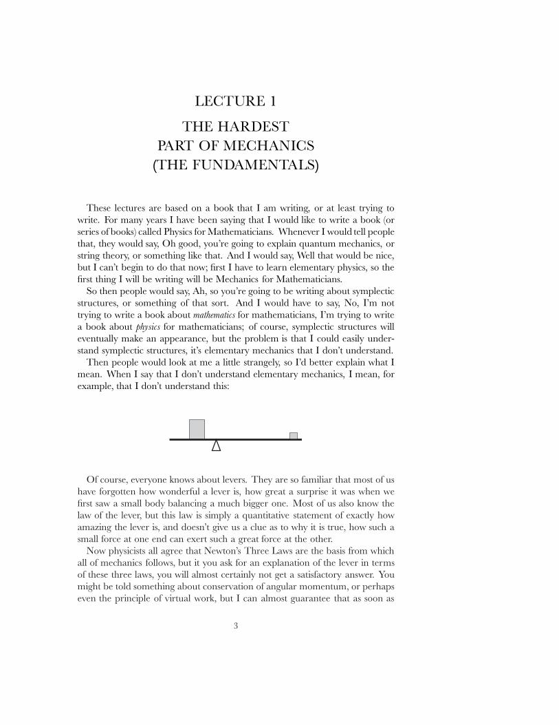
Then people would look at me a little strangely, so I'd better explain what Imean. When I say that I don't understand elementary mechanics, I mean, forexample, that I don't understand this:
Of course, everyone knows about levers. They are so familiar that most of ushave forgotten how wonderful a lever is, how great a surprise it was when weˇrst saw a small body balancing a much bigger one. Most of us also know thelaw of the lever, but this law is simply a quantitative statement of exactly howamazing the lever is, and doesn't give us a clue as to why it is true, how such asmall force at one end can exert such a great force at the other.
Now physicists all agree that Newton's Three Laws are the basis from whichall of mechanics follows, but it you ask for an explanation of the lever in termsof these three laws, you will almost certainly not get a satisfactory answer. Youmight be told something about conservation of angular momentum, or perhapseven the principle of virtual work, but I can almost guarantee that as soon as
3
LECTURE 1
some one starts to give an answer you can almost certainly interrupt them andexplain why their answer can't be correct. For, the correct answer must beginby saying \First we have to understand rigid bodies", since, after all, the rigidityof the lever is an absolute necessity for it to work, and if one hasn't alreadyanalyzed rigid bodies, then one simply isn't in a position to give an explanationof the lever.
Well, we won't get to rigid bodies for a few lectures yet, so it'll be a whilebefore we can give a good answer to this question.
In these lectures I am basically going to cover (portions of ) the part of thebook that has been written so far. The ˇnal book will contain 4 parts:
I. FundamentalsII. ApplicationsIII. Lagrangian MechanicsIV. Hamiltonian Mechanics,
with perhaps a ˇfth part,
V. Abstractions to Lie groups.
I hope to ˇnish this book in about a year. So far, I have written just Part I,and it has taken me nearly a year and a half,1 but that doesn't mean that myhope is necessarily unrealistic. After all, Part I is the hard part, all about thebasic physical ideas, while the remaining parts are basically mathematics.
We are going to be considering the foundations of mechanics by starting rightat the source, Newton's Philosophi� Naturalis Principia Mathematica or MathematicalPrinciples of Natural Philosophy, in English, or simply The Principia.
Now this book is one of the great classics, probably the greatest book in all ofphysics, but that doesn't mean that some one should try learning physics fromit! Like many a classic, it is basically unreadable. To begin with, it's in Latin,and I don't even think there is a Japanese translation. Fortunately, there is avery good recent English translation
Newton, The Principia. Translated by Bernard Cohen and Anne Whitman.
and nearly half of this hefty tome is a guide to reading the actual translation;see [N-C-W] in the References at the end of these notes for further details. Anyquotations from the Principia are taken from this book.
Newton obviously wrote the Principia with Euclid's Elements in mind. Infact, after the usual beginning stu˛, the title page, various prefaces for variouseditions, both by Newton and his editor, and a long ode to Newton written byHalley (which I haven't read, but have grave doubts of being very good), thevery ˇrst words of the Principia proper are
1 Actually about 2 years, when you count the rewriting that I felt was necessary aftergiving these lectures.
4
LECTURE 1
DEFINITIONS
Deˇnition 1 Quantity of matter is a measure of matter that arises from its density andvolume jointly.
Now of course anyone can see that this deˇnition isn't very useful, in factobviously circular, since density is usually deˇned as mass per unit volume. In[N-C-W], and elsewhere, you can ˇnd long discussions about this, but we don'treally need to be concerned. Newton is basically just trying to get started, andhe will tie things together better as he goes along. In fact, this deˇnition isimmediately followed by further discussion:
Deˇnition 1 Quantity of matter is a measure of matter that arises from its density andvolume jointly.
If the density of air is doubled in a space that is also doubled,there is four times as much air, and there is six times as much ifthe space is tripled. The case is the same for snow and powderscondensed by compression or liquefaction, : : : . Furthermore, Imean this quantity whenever I use the term \body" or \mass" inthe following pages.
The three dots here indicate omissions that aren't really very important (you'llhave to take my word for this), but there's also a portion that has been temporar-ily shaded out. This part, by contrast, is very important, but it's very confusingthat Newton put it right here, and we'll come back to it later!
Naturally, these additional remarks don't clarify the concept very much, butat least they help a little, and in particular Newton has now introduced theimportant term \mass" instead of the awkward phrase \quantity of matter". It'ssomething of a distraction that he also uses the word \body", because nowadayswe think of a body as some object, that has a particular mass, so we won't followNewton's usage at all, but will always use the word \mass", whatever in the worldthat is eventually going to mean.
The next deˇnition is a lot simpler,
5
LECTURE 1
Deˇnition 2 Quantity of motion is a measure of motion that arises from the velocity and thequantity of matter jointly.
and we merely want to point out that nowadays this is what we call \momen-tum".
The third deˇnition, though just as vague as the others, ˇnally gives us someidea of what \mass" is really supposed to mean.
Deˇnition 3 Inherent force of matter is the power of resisting by which every body, so far asit is able, perseveres in its state either of resting or of moving uniformly straightforward.
This force is always proportional to the body [i.e., mass] anddoes not di˛er in any way from the inertia of the mass except inthe manner it which it is conceived. : : :
This is certainly a strange way of speaking|nowadays, we don't speak of the\force of matter"|but, in short, what Newton is saying is that \mass" is basicallywhat we call \inertia", a measure of how hard it is to get something moving. IfI were teaching an introductory mechanics course for physics students I wouldprovide two balls like these [two balls made from styrofoam semi-spheres, iden-tical in appearance], give the ˇrst a slight push, so that it would start rollingrapidly, and then ask a brawny-looking student to repeat this with the second.[The second ball was ˇlled with heavy chain, and barely moved when pusheda great deal harder.] This little experiment shows that the second ball has amuch greater mass than the ˇrst (although the student, if asked, would proba-bly incorrectly conclude that the second ball weighed a lot more than the ˇrst,which is something quite di˛erent, that we'll get to in a bit).
Of course, all of this is merely vaguely descriptive, and the remainder ofthis ˇrst section of the Principia, in which Newton adds a few other deˇnitionsdoesn't help much.
So it's time to turn to the second section, the axioms:
AXIOMS, OR THE LAWS OF MOTION
Law 1 Every body perseveres in its state of being at rest or of moving uniformly straightforward, except insofar as it is compelled to change its state by forces impressed.
6
LECTURE 1
Of course, Newton didn't call this Newton's First Law, and, as we will seelater on, he explicitly credits the law to Galileo. Galileo didn't exactly demon-strate this law, but instead explained why everyday experiences might seem tocontradict it. Not too long ago the law might be illustrated dramatically bysliding an object along a glass table with dry ice evaporating from it, forming acushion of gas that practically eliminates friction. Recently, the invention of the\air-trough" (see reference [N-L]) has provided a nice way to illustrate Newton'sˇrst law in the classroom:
One gives the block just the tiniest nudge, and watches it glide at constantvelocity to the end of the track.
In an elementary physics course, considerable discussion about coordinatesystems might be required here, but we'll simply point out that we are basicallyassuming that there are certain coordinate systems (\inertial systems") in whichthis law holds, and that any system moving at uniform velocity with respect toan inertial system obviously has the same property. So we pass on immediatelyto
Law 2 A change in motion is proportional to the motive force impressed and takes place alongthe straight line in which that force is impressed.
If some force generates any motion, twice the force will generate twicethe motion, : : : .
Once again, we have that obnoxious shaded region, which we'll unveil at theappropriate time.
Of course, nowadays we simply state the second law as
F D ma�
7
LECTURE 1
where a is the acceleration of our body. Newton speaks in terms of (discrete)\changes in motion" because he often thinks in terms of what we would call\instantaneous" forces, exerted only for a very short time.
This law might seem to be virtually meaningless, since we haven't said howto measure mass m� nor how to measure force F� But there's really more toit than appears, as we will see by skipping to the discussion (\Scholium") thatNewton gives at the end of this section of the Principia, where he begins by ac-knowledging Galileo (again, some material has been shaded out, to be unveiledat a later date):
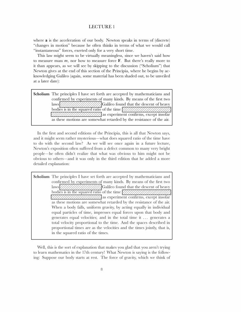
Scholium The principles I have set forth are accepted by mathematicians andconˇrmed by experiments of many kinds. By means of the ˇrst twolaws Galileo found that the descent of heavybodies is in the squared ratio of the time
as experiment conˇrms, except insofaras these motions are somewhat retarded by the resistance of the air.
In the ˇrst and second editions of the Principia, this is all that Newton says,and it might seem rather mysterious|what does squared ratio of the time haveto do with the second law? As we will see once again in a future lecture,Newton's exposition often su˛ered from a defect common to many very brightpeople|he often didn't realize that what was obvious to him might not beobvious to others|and it was only in the third edition that he added a moredetailed explanation:
Scholium The principles I have set forth are accepted by mathematicians andconˇrmed by experiments of many kinds. By means of the ˇrst twolaws Galileo found that the descent of heavybodies is in the squared ratio of the time
as experiment conˇrms, except insofaras these motions are somewhat retarded by the resistance of the air.When a body falls, uniform gravity, by acting equally in individualequal particles of time, impresses equal forces upon that body andgenerates equal velocities; and in the total time it : : : generates atotal velocity proportional to the time. And the spaces described inproportional times are as the velocities and the times jointly, that is,in the squared ratio of the times.
Well, this is the sort of explanation that makes you glad that you aren't tryingto learn mathematics in the 17th century! What Newton is saying is the follow-ing: Suppose our body starts at rest. The force of gravity, which we think of
8
LECTURE 1
as an instantaneous force acting at time 0� changes the downward velocity bya small increment v� So after a small increment of time t the body has fallenby an amount vt� Then its velocity receives an additional increment v� givingit velocity 2v so after the next increment t of time it falls by the amount 2vt�
In the next increment of time it falls by the amount 3vt� then by the amount4vt� etc. So at the end of a large number N of such increments it has fallen.1 C 2 C 3 C � � � C N/ times vt� which is close to N 2vt=2� or to vT 2=2� where T
is the total time it has fallen. Nowadays, of course, we just say, If s00 D a for aconstant a� then s0 D at� and thus s D 1
2 at2�
Even after all this explanation, you might wonder what this has to do withthe second law, since it seems to be a purely mathematical result about secondderivatives. So it's important to go back and look at one particular phrase inNewton's argument:
When a body falls, uniform gravity, by acting : : :
What does Newton mean here by \uniform gravity"? You might think he meansthat gravity produces the same acceleration on the body no matter what velocityit already has (and this is indeed one of the things he is assuming), but Newtonis also appealing (implicitly, it is true) to an important fact that we can testexperimentally.
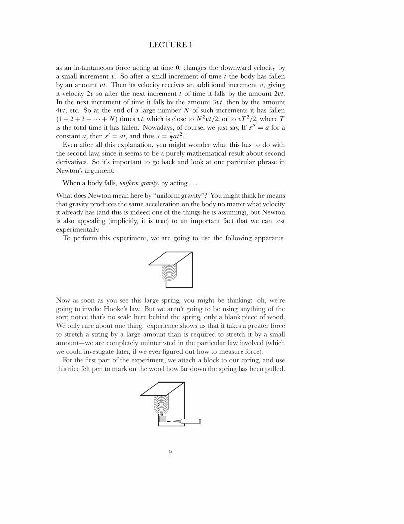
To perform this experiment, we are going to use the following apparatus.
Now as soon as you see this large spring, you might be thinking: oh, we'regoing to invoke Hooke's law. But we aren't going to be using anything of thesort; notice that's no scale here behind the spring, only a blank piece of wood.We only care about one thing: experience shows us that it takes a greater forceto stretch a string by a large amount than is required to stretch it by a smallamount|we are completely uninterested in the particular law involved (whichwe could investigate later, if we ever ˇgured out how to measure force).
For the ˇrst part of the experiment, we attach a block to our spring, and usethis nice felt pen to mark on the wood how far down the spring has been pulled.
9
LECTURE 1
Of course, this isn't a high-tech experiment, it's a Tokyu Hands experiment.1
But we could easily imagine a much more reˇned experiment, with a very strongspring, very accurate ways of measuring its displacement, etc.
For the sake of time, I'll simply describe the second part of the experiment,instead of having us actually perform it. For this part of the experiment, wewould all go upstairs to the room above this one. Perhaps there's some onethere now, well, we'll just ask them if we can take a moment's time to performa simple experiment. And this simple experiment is a repeat of the experimentthat we have just done here: we attach the block to our spring, and see far downthe spring has been pulled. It appears that the spring has been pulled downexactly the same amount. (At least within the accuracy of our Tokyu Handsexperiment.)
The next part of the experiment is one that probably no one except a touristlike myself might be willing to perform, taking the same measurement at thetop of Tokyo Tower. Once again, it seems that the spring is stretched by exactlythe same amount.
Now this is what Newton means when he speaks of \uniform gravity": a forcethat is the same no matter how high up we go (of course, that's not really truefor the force of gravity, but it's true to a very good approximation for the sortof distances above the earth's surface that we are concerned with). The pointis that we can at least say when two forces are equal without having to specify away of measuring them.
Thus, the experimental evidence that the force of gravity is equal at all rea-sonable distances from the earth's surface is consistent with the equality ofacceleration along the path of a falling object, which is essentially equivalent toGalileo's observation that \the descent of heavy bodies is in the squared ratioof the time".
It may seem a long way from \equal forces produce equal accelerations" to\force equal mass times acceleration", but that's mainly because we still haven'tgiven an \operational deˇnition" of mass, describing how it is to measured. Theimportant point is that the results of our little experiment actually suggest a wayof producing such an operational deˇnition.
We'll begin with a deˇnition that is conceptually very straightforward, al-though it would be rather awkward to use in practice.
First we want to have a very long air-trough, with a carriage, of negligiblemass, in which we can place a body whose mass we want to measure. Parallelto this air-trough we have a track with a little cart that can be pulled along thetrack with any desired acceleration a; for simplicity, let's imagine that we merelyhave to turn a knob on an instrument panel to vary a� without worrying aboutthe clever mechanism that would be required to produce this e˛ect. Of course,
1 Tokyu Hands is a large do-it-yourself and hobby store where all the paraphernalia forthis lecture was purchased.
10
LECTURE 1
our track, and the air-trough, will also have to be very long if we expect to pullthe cart with constant acceleration a for any reasonable amount of time.
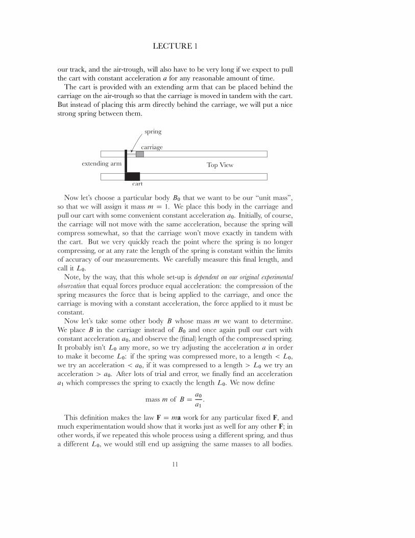
The cart is provided with an extending arm that can be placed behind thecarriage on the air-trough so that the carriage is moved in tandem with the cart.But instead of placing this arm directly behind the carriage, we will put a nicestrong spring between them.
Now let's choose a particular body B0 that we want to be our \unit mass",so that we will assign it mass m D 1� We place this body in the carriage andpull our cart with some convenient constant acceleration a0� Initially, of course,the carriage will not move with the same acceleration, because the spring willcompress somewhat, so that the carriage won't move exactly in tandem withthe cart. But we very quickly reach the point where the spring is no longercompressing, or at any rate the length of the spring is constant within the limitsof accuracy of our measurements. We carefully measure this ˇnal length, andcall it L0�
Note, by the way, that this whole set-up is dependent on our original experimentalobservation that equal forces produce equal acceleration: the compression of thespring measures the force that is being applied to the carriage, and once thecarriage is moving with a constant acceleration, the force applied to it must beconstant.
Now let's take some other body B whose mass m we want to determine.We place B in the carriage instead of B0 and once again pull our cart withconstant acceleration a0� and observe the (ˇnal) length of the compressed spring.It probably isn't L0 any more, so we try adjusting the acceleration a in orderto make it become L0: if the spring was compressed more, to a length < L0�
we try an acceleration < a0� if it was compressed to a length > L0 we try anacceleration > a0� After lots of trial and error, we ˇnally ˇnd an accelerationa1 which compresses the spring to exactly the length L0� We now deˇne
mass m of B Da0
a1:
This deˇnition makes the law F D ma work for any particular ˇxed F� andmuch experimentation would show that it works just as well for any other F; inother words, if we repeated this whole process using a di˛erent spring, and thusa di˛erent L0� we would still end up assigning the same masses to all bodies.
11

LECTURE 1
Then, of course, we can use the equation in reverse, as a way of measuring force,by seeing what acceleration is produced on a body of some known mass m�
Before proceeding further, two points should be made. First, our original littleexperiment is certainly consistent with F D ma� but it would hardly seem to bevery conclusive. After all, how do we know that the correct law isn't somethinglike F D ma C ka0 for some constant k� so that third derivatives, or even higherderivatives, are involved? I don't know of any experiments to directly test this,but of course there is an enormous body of experience that attests to it: theforce of gravity isn't constant over large distances, so all the calculations thatkeep satellites in motion, guide space ships to the moon and land them, etc.,present a great deal of evidence.
A second point to ponder is that we always take for granted that mass is\additive": if we take bodies of mass m1 and m2 and join them together (forexample, by placing them together in the carriage on our air-trough), then thenew object should have mass m1 C m2� In terms of our operational deˇnition,this hardly seems clear: it says that if a1 is the acceleration that the ˇrst bodymust be subjected to in order to compress the spring to length L0� while a2 isthe acceleration that the second body must be subjected to in order to compressthe string the same amount, then to obtain the same compression for the twoobjects together, they must be subject to an acceleration a satisfying
1
aD
1
a1C
1
a2
to obtain the same compression. At ˇrst glance, this might seem to be a strangefact that could only be veriˇed by experiments with large numbers of varyingmasses, so it is interesting to try to ˇgure out what reasonable body of basicexperimental facts would lead one to the additivity of mass in a more reasonablemanner, an exercise you might like to think about before the next lecture.
Finally, here is a less direct, but more convenient operational deˇnition ofmass, based on the mathematician's and physicist's common view that a straightline is just a circle of inˇnite radius.
Instead of using an air-trough, we simply attach our body B to the end ofa very sti˛ spring that is being rotated horizontally with some large constant\angular frequency" ˛� so that B moves along the circle
c.t/ D R.cos ˛t; sin ˛t/
for some radius R� This radius R will be somewhat larger than the unstretchedlength of the spring, because B actually begins moving along a spiral, pullingthe spring out, though its path soon becomes indistinguishable from a circle.For the acceleration we simply have
(A) c00.t/ D �R˛2.cos ˛t; sin ˛t/�
12
LECTURE 1
so that the acceleration always points directly inward, and has magnitude R˛2�
This means that the force F that the spring exerts on B also always pointsdirectly inward and has constant magnitude.
Declaring B to be our unit of mass amounts to saying that
(a) jFj D 1 � R˛2:
To determine the mass m of any other body, we attach it to the end of ourspring and vary the angular frequency with which we rotate it until we arriveat an angular frequency ˇ for which our body is moving along a circle
c.t/ D R.cos ˇt; sin ˇt/
of the same radius R� Now we should have
(b) jFj D m � Rˇ2�
with the jFj in equations (a) and (b) having the same value, since in both casesthe spring has been stretched by the same amount. In other words, we candetermine m by
m D ˛2=ˇ2:
We've ignored the e˛ect of gravity on these bodies, but that would becomenegligible in comparison to the force of our sti˛ spring when ˛ is large, or wemight imagine the measurements being made in outer space.
I'm sure that the basic mechanism for this deˇnition could be greatly reˇned.Instead of a spring, one might whirl a tube ˇlled with mercury, and measurethe compression of this mercury column, etc. But I don't think any one hasever actually produced a mechanism of this sort. In fact, as far as I know, noone has ever measured the mass of anything accurately. This statement obviouslyrequires a bit of explanation!
Let's consider these two balls, which we used previously in a little \experi-ment" to illustrate the concept of mass, and again enlist the aid of the studentwho performed the experiment, and quite possibly stated, incorrectly, that theexperiment showed that the second ball had a greater weight than the ˇrst(rather than a greater mass). We could then continue the experiment by takingeach of the balls o˛ the table, in turn, and having the student hold it. Almostno e˛ort would be required to hold up the ˇrst ball [as you can see when Ihold it up], while considerably more e˛ort would be required for the secondball [as you can now see me straining a bit to hold up the second ball]. Thissecond experiment shows that the weight of the second ball|a measure of thegravitational force exerted on it by the earth|is much greater than the weightof the ˇrst.
In the ˇrst experiment, the e˛ect of this gravitational force was irrelevant(except insofar as it a˛ected friction), because the table was counteracting this
13
LECTURE 1
force, so we were simply comparing the mass of the two bodies, while the sec-ond experiment directly compares the weight of the two bodies. So one of theˇrst things that every beginning physics student needs to learn is the di˛erencebetween mass and weight. For modern students, it's probably especially easy toillustrate this di˛erence by considering what happens in a freely moving spacecraft where everything has no weight at all, so that these two balls would simply oat where ever they were placed, but where moving one of the balls would be alot more diıcult than moving the other.
On the other hand, once we've clariˇed this distinction, we have to confusethe students once again, by pointing out that the relative masses of two bodiesseem to be the same as their relative weights|everyday experience would cer-tain have led us to conclude, without even thinking about it, that the secondball, so much harder to set in motion, would also be much harder to lift.
In terms of the second law, we can make a much more speciˇc correlation:Since the weight of an object, of mass m� say, is the force F of gravity on it,the law F D m � v0 means that the ratio F=m of weight to mass is simply theacceleration that an object undergoes under free fall. Thus, proportionality ofweight to mass is equivalent to the assertion that all bodies fall with the sameacceleration, the famous fact usually attributed to Galileo.
Aristotle, as we all know, had claimed that large bodies fall faster than smallerones, and people apparently believed this for many centuries afterward, butit never made much sense. Even before Galileo's experiment, a man namedJ.-B. Benedetti (1530-1590) had pointed out how absurd this would be (see [M],Chapter II, section I, 2). After all, suppose we drop a brick like this one [luckily,it was a fake brick, so it didn't hurt the oor], and then take two of these bricks,tape them together, and drop them side by side: why in the world would thetwo bricks fall faster than each individual brick? But Benedetti still thoughtthat denser bodies would fall more rapidly than less dense ones, and Galileois usually credited with being the ˇrst to realize that even bodies with di˛eringcompositions, like wood and iron, fall at the same rate. Modern physicists wouldchoose something like aluminum and gold, which have such di˛erent ratios ofprotons and neutrons, because, after all, we're really saying that everything, eveneach of the elementary particles, falls at the same rate!
Newton, of course, would never had made Aristotle's ˇrst mistake, and cer-tainly realized that it was a question of whether bodies of di˛ering compositionsfall at the same rate. Although Galileo had performed experiments to deter-mine this, Newton wanted much more accurate results, and he informs us ofthis right at the beginning of the Principia.
Recall that the Principia begins with a deˇnition that we previously showedwith some material blocked out.
Deˇnition 1 Quantity of matter is a measure of matter that arises from its density andvolume jointly.
14
LECTURE 1
If the density of air is doubled in a space that is also doubled,there is four times as much air, and there is six times as much ifthe space is tripled. The case is the same for snow and powderscondensed by compression or liquefaction, : : : . Furthermore, Imean this quantity whenever I use the term \body" or \mass" inthe following pages.
Adding in the remaining material we have
Deˇnition 1 Quantity of matter is a measure of matter that arises from its density andvolume jointly.
If the density of air is doubled in a space that is also doubled,there is four times as much air, and there is six times as much ifthe space is tripled. The case is the same for snow and powderscondensed by compression or liquefaction, : : : . Furthermore, Imean this quantity whenever I use the term \body" or \mass" inthe following pages. It can always be known from a body's weight,for|by making very accurate experiments with pendulums|I havefound it to be proportional to the weight, as will be shown below.
This was certainly a confusing place for Newton to place this remark ( just ashe is introducing the notion of mass, which he wants to distinguish from weight!),and it must have been all the more confusing when he added the phrase \as willbe shown below". Normally, one would expect this phrase to refer to materialat the bottom of the page, or perhaps just a few pages later on. But Newton's\shown below" actually refers to material about 400 pages later in his book!
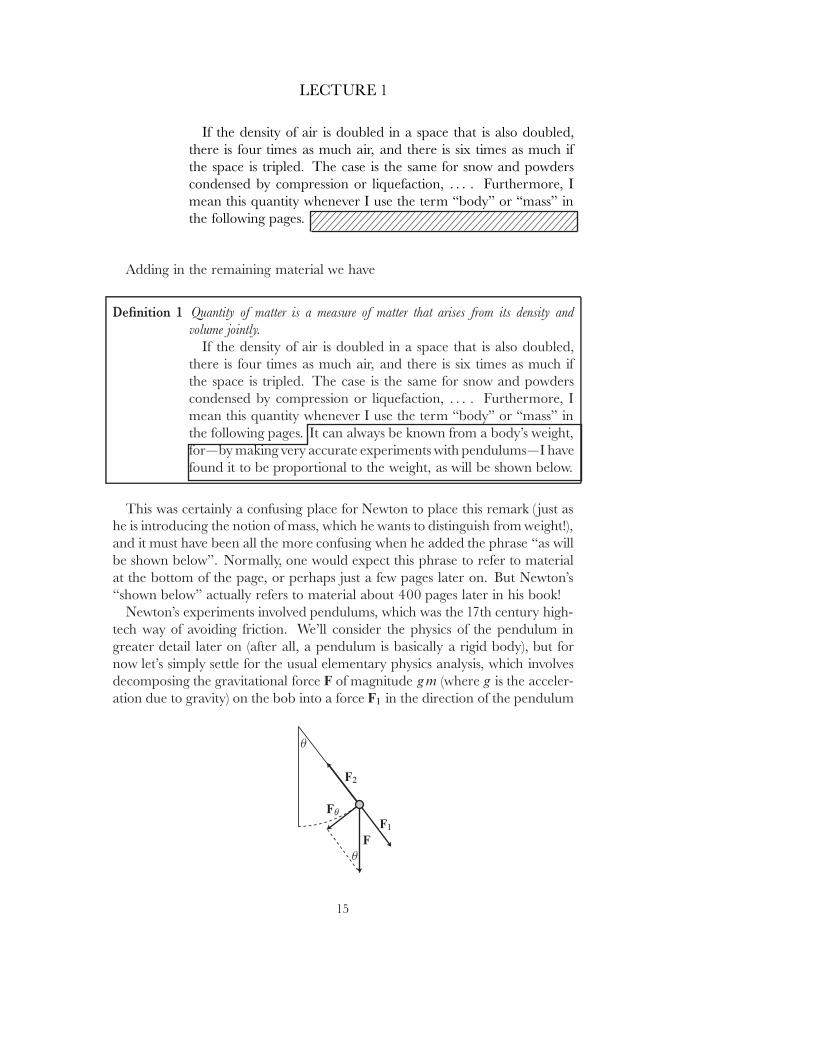
Newton's experiments involved pendulums, which was the 17th century high-tech way of avoiding friction. We'll consider the physics of the pendulum ingreater detail later on (after all, a pendulum is basically a rigid body), but fornow let's simply settle for the usual elementary physics analysis, which involvesdecomposing the gravitational force F of magnitude gm (where g is the acceler-ation due to gravity) on the bob into a force F1 in the direction of the pendulum
15
LECTURE 1
string and another force F� tangent to the path of the bob. The string is alsoexerting a force, F2� on the bob, which is assumed to point along the directionof the string. We must have F2 D �F1� since we assume that the bob stays at aconstant distance from the pivot point, keeping the string taut but not stretchingit out. Thus, the net force on the bob is F C .�F1/ D F� � and consequently theacceleration of the bob, tangent to the circular path, has magnitude
(1) a� D g sin �:
If we consider � as a function of time, and let l be the length of the string(the radius of the circle on which the pendulum bob moves), then equation (1)yields
� 00 Cg
lsin � D 0:
Physicists virtually always restrict their attention to the case of \small oscilla-tions" (� � 0), so that they can replace sin � by � and get an equation that theycan solve. But the information we need, and that Newton relied on, doesn'trequire that consideration, and is a pure similarity argument.
For convenience, we choose the origin O to be the point from which thependulum hangs. Then for any ˛ > 0 the path
.t/ D ˛ � c�t=
p˛�
follows a circle with radius ˛ times the radius of the path c� but with the timereparameterized by the factor 1=
p˛� So the angle #.t/ for satisˇes
#.t/ D�.t/p
˛�
and it follows that# 00 C
g
˛lsin # D 0:
This means that gives the path of a pendulum bob with length ˛ times that ofthe original, and we easily conclude that the period of the pendulum describedby is
p˛ times the period of the pendulum described by c: the period of a
pendulum is proportional to the square root of its length.A similar argument, left to you, shows that if the acceleration g were replaced
by g � ˛� then the period of the pendulum would become 1=p
˛ times the orig-inal period; so the periods T1 and T2 of a pendulum bob undergoing di˛erentaccelerations g1 and g2 are related by
(�)g2
g1D
T12
T22:
Newton phrased this result in a somewhat di˛erent way. If two objects, ofmasses m1 and m2� have gravitational accelerations g1 and g2� and we denotetheir weights by W1 D g1m1 and W2 D g2m2� then (�) can be written as
m1
m2D
W1
W2�
T12
T22:
16

LECTURE 1
This result ˇrst occurs in the Principia about 300 pages from the beginning, amere 100 pages before Newton's description of his pendulum experiments, andI think it will be amusing to quote it as it appears:
Proposition 24 In simple pendulums whose centers of oscillation agree equally distant fromthe center of suspension, the quantities of matter are in a ratio compoundedof the ratio of the weights and the squared ratio of the times of oscillation: : : .
For the velocity that a given force can generate in a giventime in a given quantity of matter is as the force and the timedirectly and the matter inversely. : : : Now if the pendulums areof the same length, the motive forces in places equally distantfrom the perpendicular are as the weights, and this if two os-cillating bodies describe equal arcs and if the arcs are dividedinto equal parts, then, since the times in which the bodies de-scribe single corresponding parts of the arcs are as the times ofthe whole oscillations, the velocities in corresponding parts ofthe oscillations will be to one another as the motive forces andthe whole times of the oscillations directly and the quantities ofmatter inversely; and thus the quantities of matter will be as theforces and the times of the oscillations directly and the veloci-ties inversely. But the velocities are inversely as the times, andthus the times are directly, and the velocities are inversely, asthe squares of the times, and therefore the quantities of matterare as the motive forces and the squares of the times, that is, asthe weights and the squares of the times. Q.E.D.
I haven't the slightest idea what any of this means! But I'm almost certainthat it amounts to the similarity argument we have given. Aren't you glad thatyou aren't a mathematician of the 17th century!?
About 100 pages later Newton describes how he tested
(�)g2
g1D
T12
T22�
and thus the proportionality of weight to matter, with equal weights of \gold,silver, lead, glass, sand, common salt, wood, water, and wheat". Each pairof materials to be tested was enclosed within one of two rounded, equal-sizedwooden boxes. For the wood bob he simply ˇlled the inside of the box withmore wood, but for the gold bob he suspended the gold at the center of thebox; he then hung each of the two boxes by eleven-foot cords, which \madependulums exactly like each other with respect to their weight, shape, and airresistance."
17
LECTURE 1
He then started them swinging close to each other from the same height,noting that \they kept swinging back and forth together with equal oscillationsfor a very long time. : : : And it was so for the rest of the materials. In theseexperiments, in bodies of the same weight, a di˛erence of matter that would beeven less than a thousandth part of the whole could have been clearly noticed."
Of course, once we know that weight is exactly proportional to mass, there'sno longer any need to measure mass accurately. To compare the mass of twoobjects, we simply have to compare their weights, and weights can easily bemeasured very accurately, with a balance scale. A balance scale is a special sortof lever, one in which the lever arms have the same length, but we don't needto understand the lever to use the balance scale, since symmetry implies thattwo objects that balance at the same distance from the pivot point must havethe same weight ( just to be on the safe side, we would probably interchange thetwo objects for a second check).
Clever experiments have allowed Newton's result to be veriˇed to muchgreater accuracy in later times, and you can read in physics books about the 19thcentury E�otv�os experiment (see, for example, [Fr]) and the 1964 experiment ofRoll, Krotkov, and Dicke (described in [M-T-W]) which veriˇed proportionalityof weight to mass within 1 part in 1011 for gold and aluminum. The only thing Iwould like to point out here is that in both of these experiments, as in Newton'soriginal experiment, we never actually measure the mass of anything! We onlymeasure weights.
At this point, I think I would have to reassure the students in our elementaryphysics class by saying:
You may be starting to feel somewhat overwhelmed. First we insisted ondistinguishing between mass and weight. Then we claimed that this distinctiondidn't really seem to matter, because weight was proportional to mass. Finally,we noted that we established this fact to great accuracy without even being ableto measure mass to great accuracy! Don't worry! Every one before Newtonwas just as confused as you were! Newton was the ˇrst person to really makethe distinction between mass and weight, and his decision to make mass andforce the basic concepts in terms of which others should be deˇned|and tochoose the ˇrst two laws as the basis for deducing other results|was one ofNewton's main achievements. That's why we still speak of classical mechanicsas Newtonian Mechanics.
The ˇrst two laws, on which we have spent so much time, involve individualbodies, but say nothing about the interactions between di˛erent bodies. Thisinformation is given by Newton's third law, and since all of mechanics rests onNewton's three laws, this last one must be quite special.
In fact, it is usually stated in a way that almost guarantees its misuse in philo-sophical and political discourse:
Law 3 To any action there is always an opposite and equal reaction
18
LECTURE 1
But Newton's statement was much more speciˇc
Law 3 To any action there is always an opposite and equal reaction; in other words, the actionsof two bodies upon each other are always equal and always opposite in direction.
Thus, the third law always involves two di˛erent bodies, each exerting a forceon the other. Most misuses and invalid analogues of the third law ignore thisbasic fact that the two actions in question are exerted on two di˛erent bodies.
Although I've made a snide comment about philosophers' and political the-orists' misuse of the third law, mathematicians and scientists themselves rarelyappreciate the true signiˇcant of this law and its consequences. In a typicalˇrst-year physics course the law is simply stated, with one or two examples, andthen earnestly applied to the solution of mechanics problems, with every onecarefully drawing force diagrams to specify all the di˛erent reaction forces in-volved. Almost no mention is even made of the experimental evidence for thislaw!
There is, however, one consequence of the third law that is always mentioned.Consider the collision of two objects: B1� having mass m1� and B2� havingmass m2� During the collision, B2 will be exerting a force F12 on B1� while B1
will be exerting a force F21 on B2 (the ˇrst subscript indicates the body on whichthe force acts). We should really write F12.t/ and F21.t/ because these forcesmay vary with time; in fact, they presumably vary in an incredibly complicatedway, depending on the particular way that the two bodies are compressed, spin,vibrate, undulate, bobble, etc. But we always have F12.t/ D �F21.t/� so for alltimes t we have
.m1v1 C m2v2/0.t/ D .m1v1/0.t/ C .m2v2/0.t/
D F12.t/ C F21.t/
D 0:
Thus, no matter how complicated the collision may be, the \total momentum"m1v1 C m2v2 is constant. Or, as we like to say, momentum is conserved.
This result appears in the Principia as a Corollary of the three laws, and wewill quote it here, together with the proof, just to give another example of the avor of mathematical writing at that time:
Corollary 3 The quantity of motion, which is determined by adding the motions made inone direction and subtracting the motions made in the opposite direction, is notchanged by the action of bodies on one another.
For an action and the reaction opposite to it are equal by law 3,and thus by law 2 the changes which they produce in motions areequal and in opposite directions. Therefore, if motions are in thesame direction, whatever is added to the motion of the eeing body
19

LECTURE 1
will be subtracted from the motion of the pursuing body in sucha way that the sum remains the same as before. But if the bodiesmeet head-on, the quantity subtracted from each of the motionswill be the same, and thus the di˛erence of the motions made inopposite directions will remain the same.
The separate consideration of the case of two bodies moving toward eachother and the case of one body overtaking another seems awfully awkward tous, but, as we will soon see, Newton may have had a speciˇc reason for makingthe distinction clear.
This corollary of third law, usually presented as a neat consequence in physicsclasses, is actually the experimental evidence upon which Newton originallyrelied. In fact his Scholium tells us
Scholium The principles I have set forth are accepted by mathematicians andconˇrmed by experiments of many kinds.
: : :
: : : Sir Christopher Wren, Dr. John Wallis, and Mr. Christiaan Huy-gens, easily the foremost geometers of the previous generation, inde-pendently found the rules of the collisions and re ections of hardbodies, and communicated them to the Royal Society at nearly thesame time.
This short sentence, o˛-handedly mentioning the near simultaneous commu-nication of the same results, has a bit of history behind it.
Descartes seems to be the ˇrst person to have stated the law of Conservationof Momentum, o˛ering the reasoning that since God made the Universe witha certain amount of momentum in it, obviously He would not allow this mo-mentum to be changed (I admit that those aren't his exact words, but they arenot an unfair paraphrase; see [D], Chapter 4, section 3 for an exact statement).One might feel that although this would not be the sort of argument to be ac-cepted in modern physics journals, at least he did state the law. Unfortunately,however, Descartes didn't even state the law correctly, because he didn't think ofmomentum as a vector quantity, or even|for the case of bodies colliding alonga straight line, the special case that people tended to restrict their attention toin those days|as a signed quantity, so he was really assuming that the abso-lute value of momentum was conserved. He then deduced from his principlea long series of consequences about colliding bodies, almost all of which areincorrect. Moreover, Descartes knew that his deductions didn't seem to accordwith experiment, but blithely dismissed this as due to experimental errors!
20
LECTURE 1
Naturally, not every one was so convinced, so the Royal Society had asked forresearch into the proper rules, and this was the impetus for the communicationsof Wren, Wall, and Huygens.
You might assume that, unlike Descartes, these three men simply carriedout experiments to see what actually happened, but that's not quite the case.Newton goes on to say
: : : Sir Christopher Wren, Dr. John Wallis, and Mr. Christiaan Huy-gens, easily the foremost geometers of the previous generation, inde-pendently found the rules of the collisions and re ections of hardbodies, and communicated them to the Royal Society at nearly thesame time, : : : But Wren additionally proved the truth of these rulesbefore the Royal Society by means of an experiment with pendulums: : :
Although Wallis and Huygens didn't do experiments, the \thought exper-iments" of Huygens happen to be extremely interesting, and we will considerthem at a later time. But right now we want to brie y discuss those experimentswith pendulums.
As we've already mentioned, pendulums were the 17th century way of practi-cally eliminating friction, and they have an additional virtue: By observing howhigh a body swings past the lowest point, one can ˇgure out the velocity thatit had at that lowest point. Thus, Wren could determine both the velocities oftwo bodies just as they collided at the bottom of their pendulum arcs with thevelocities that they obtained right after the collision.
After mentioning Wren's experiments, Newton proceeds to give details of hisown experiments, designed to check the results with much greater accuracy, andhe spends three entire pages describing them (these experiments are completelydi˛erent from the ones used to verify proportionality of weight and mass, whichoccur much later, though mentioned at the very beginning of the Principia).
Newton is actually being rather modest in saying that \the principles I haveset forth are accepted by mathematicians : : : " because, as far as the third lawis concerned, it had only appeared in this form, as conservation of momen-tum, and it was Newton who then worked backward to formulate his third law.Moreover, Newton took the truly audacious step of generalizing this law, basedonly on one particular physical phenomenon, the (totally unknown) forces in-volved in the collision of bodies, to arbitrary forces. One of the forces thatNewton was particularly concerned about, of course, was gravity, but it will bequite interesting to ˇrst consider another force with which we are all familiar,namely, magnetism.
I'd like to consider a simple experiment, but I'll have to be content withdescribing it, rather than performing it, because it would require an air-trough,as well as rather strong magnets, stronger than I could ˇnd at Tokyu Hands,and a few other bits of modern technology, like a strobe light.
21
LECTURE 1
We simply place a magnet and a piece of iron on the air-trough, releasethem, and make accurate measurements of their positions over very many smallintervals of time. This allows us to determine their velocities at these times, andcheck that the total momentum at all such times is the same.
But we can also make a convincing case without doing any measurements atall, by considering what happens when we release the magnet and the piece ofiron simultaneously (so that they have total momentum 0 at that moment). Iwould really like to try this experiment with a class of naive physics students,after having ˇrst shown some collisions when the two are not released simulta-neously, just to confuse the issue a bit. It would be interesting to present twodi˛erent scenarios, one in which the magnet is small, and the piece of ironquite large, and one in which the situation is reversed, and ask students whatthey think will happen. I don't know, of course, because I haven't tried this(sociology) experiment, and the results would certainly depend on the sophis-tication of the students involved, but I wouldn't be surprised if many studentswould suspect that the heavier body would end up pushing the lighter one.
Of course, once we start thinking along the lines of conservation of momen-tum, we see that when the magnet and iron collide, no matter what their relativemasses are, they must come to a dead stop, since their total momentum must al-ways be the same as at the beginning, namely 0� Moreover, this one observationshould suıce to convince us of conservation of momentum in this experiment,without making any of the intermediate measurements: Since the total momen-tum at the moment of collision is 0� it must have been very close to 0 just beforethe collision. But we can obtain a whole range of velocities just before collisionsimply by varying the initial distance between the magnet and iron|or, equiv-alently, by varying the strength of the magnet. Thus the total momentum mustalways be zero!
This experiment could just as well have been carried out using two magnets,but I chose a magnet and a piece of iron to point out the unintuitive aspect of thethird law, which I would emphasize to a physics class by another simple pair ofexperiments.
Let us once again start with a magnet and a piece of iron held in place, andthen simply release the iron, so that it hurtles toward the magnet. What does thisexperiment show? Well, obviously, that the magnet exerts a force on the iron;or, in more formal terms, that iron undergoes an acceleration in the presence ofa magnet. Now we repeat the experiment, this time keeping the iron ˇxed, andreleasing the magnet, which goes rushing toward the iron. Again we ask, whatdoes this experiment show? Quite likely, many would say that it just shows thesame thing, that a magnet exerts a force on the iron. But, of course, it doesn'tshow anything of the sort, since we don't observe the iron moving. What itshows is that iron exerts a force on the magnet. But we tend not to think in thoseterms. Normally we think of a piece of iron as a hunk of matter pretty muchlike any other piece. The magnet is something special, it exerts a force on the
22
LECTURE 1
iron. But, in addition, the iron becomes special at the same time, something wemay not usually acknowledge. If we take one of those cute little magnets thatpeople use to hold notes on a refrigerator door, and hold it near the refrigerator,we don't notice the refrigerator moving toward the magnet! Instead, we feel themagnet being pulled toward the refrigerator. Nevertheless, people don't usuallygo around saying that refrigerators attract magnets. What's truly amazing, ofcourse, is that not only does iron attract magnets, but it does so in exactly theright amount so that conservation of momentum holds.
Remarkably enough, our modern understanding of magnetism happens tomake this wonderful reciprocity quite understandable: the individual atoms ofthe iron each act as magnets, except that they are oriented randomly, and themagnet causes them to align, so that the iron now acts as a magnet also. So,ultimately, it's all a matter of iron atoms attracting each other, and we have acompletely symmetric situation.
That same argument, of course, would make it quite clear why two objectsthat have been given static electric charges should exert forces of equal magni-tude on each other, since ultimately it's all due to the mutual repulsive forcesbetween electrons.
Strangely enough, it's actually the most common example, the repulsive forceof colliding bodies, that now seems the most mysterious. Presumably this in-stance of the third law has to reduce to the third law operating on any pair ofparticles. So it must hold, for example, for a proton and a neutron, where thesituation seems decidedly unsymmetric. In fact, it starts to be clear that if onereally understood the third law, one would basically understand all of atomicphysics.
I should mention that the little experiment involving a magnet and piece ofiron that I have concocted, and which I feel would make a great teaching tool,was inspired by something Newton said, but hardly something for which I wouldpraise him; in fact, it may be the silliest thing that Newton ever said (or, at anyrate, the silliest scientiˇc statement he ever made).
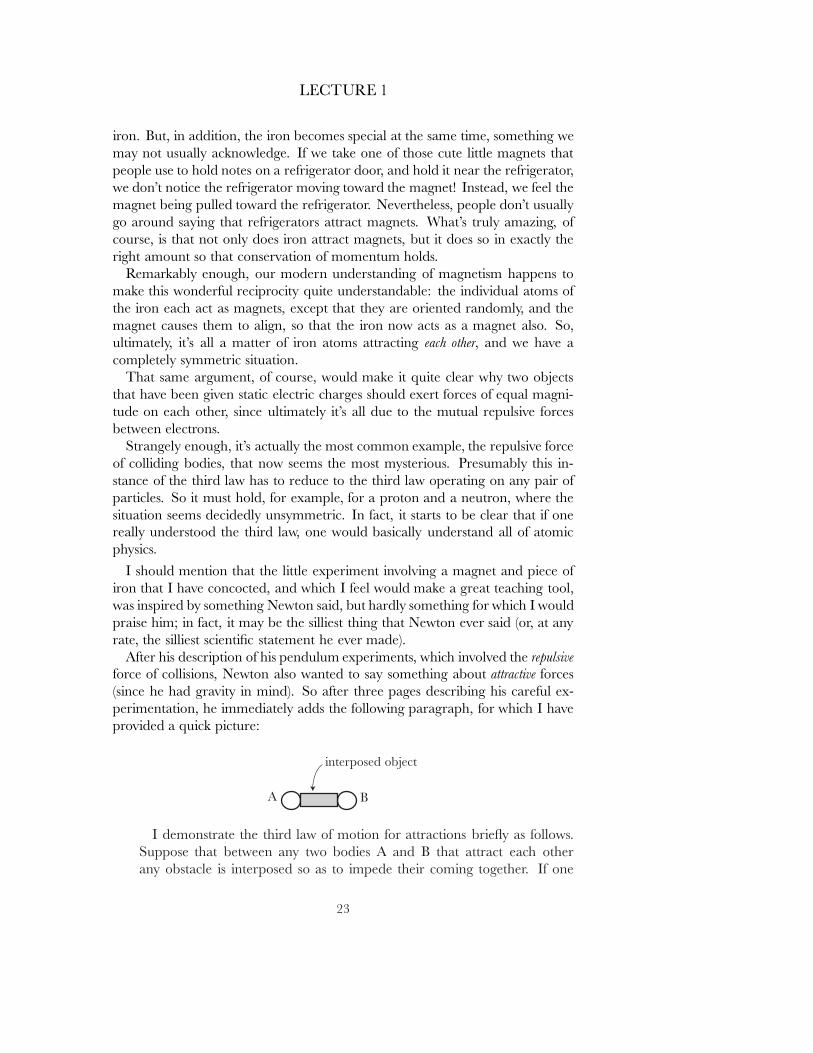
After his description of his pendulum experiments, which involved the repulsiveforce of collisions, Newton also wanted to say something about attractive forces(since he had gravity in mind). So after three pages describing his careful ex-perimentation, he immediately adds the following paragraph, for which I haveprovided a quick picture:
I demonstrate the third law of motion for attractions brie y as follows.Suppose that between any two bodies A and B that attract each otherany obstacle is interposed so as to impede their coming together. If one
23
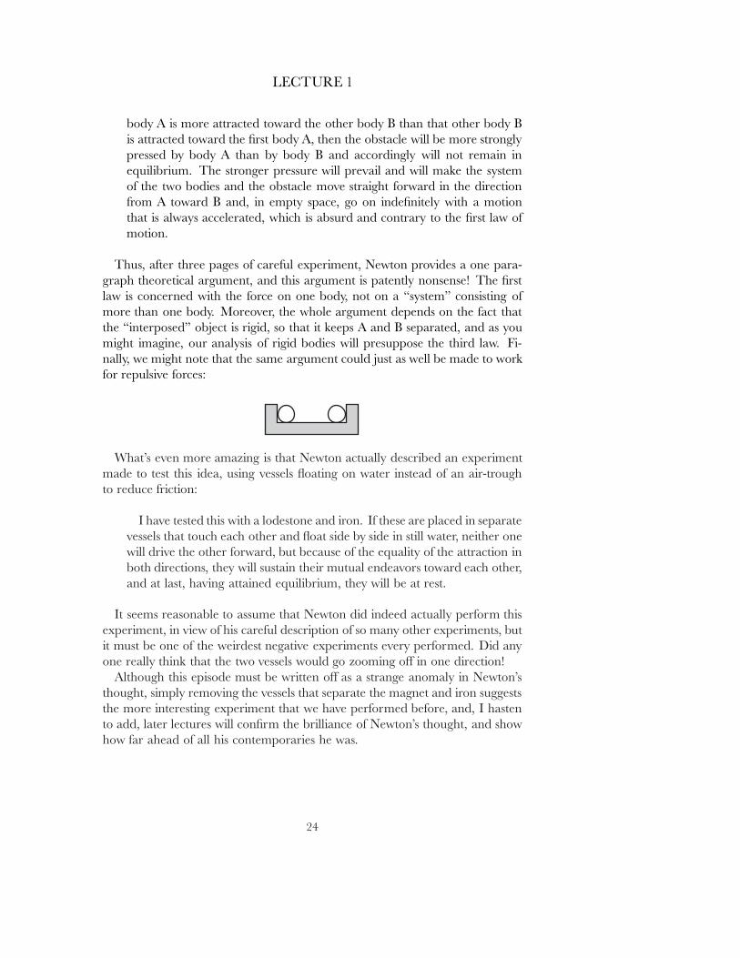
LECTURE 1
body A is more attracted toward the other body B than that other body Bis attracted toward the ˇrst body A, then the obstacle will be more stronglypressed by body A than by body B and accordingly will not remain inequilibrium. The stronger pressure will prevail and will make the systemof the two bodies and the obstacle move straight forward in the directionfrom A toward B and, in empty space, go on indeˇnitely with a motionthat is always accelerated, which is absurd and contrary to the ˇrst law ofmotion.
Thus, after three pages of careful experiment, Newton provides a one para-graph theoretical argument, and this argument is patently nonsense! The ˇrstlaw is concerned with the force on one body, not on a \system" consisting ofmore than one body. Moreover, the whole argument depends on the fact thatthe \interposed" object is rigid, so that it keeps A and B separated, and as youmight imagine, our analysis of rigid bodies will presuppose the third law. Fi-nally, we might note that the same argument could just as well be made to workfor repulsive forces:
What's even more amazing is that Newton actually described an experimentmade to test this idea, using vessels oating on water instead of an air-troughto reduce friction:
I have tested this with a lodestone and iron. If these are placed in separatevessels that touch each other and oat side by side in still water, neither onewill drive the other forward, but because of the equality of the attraction inboth directions, they will sustain their mutual endeavors toward each other,and at last, having attained equilibrium, they will be at rest.
It seems reasonable to assume that Newton did indeed actually perform thisexperiment, in view of his careful description of so many other experiments, butit must be one of the weirdest negative experiments every performed. Did anyone really think that the two vessels would go zooming o˛ in one direction!
Although this episode must be written o˛ as a strange anomaly in Newton'sthought, simply removing the vessels that separate the magnet and iron suggeststhe more interesting experiment that we have performed before, and, I hastento add, later lectures will conˇrm the brilliance of Newton's thought, and showhow far ahead of all his contemporaries he was.
24
LECTURE 2
FURTHER REMARKSON THE FUNDAMENTALS
In the previous lecture I pointed out that our operational deˇnition of massdidn't seem to provide any clear reason why mass should be additive, and chal-lenged people to ˇnd a reasonable explanation of this phenomenon. That wasa challenge that I myself wasn't prepared to meet at the time, but I think thefollowing would be a good answer.
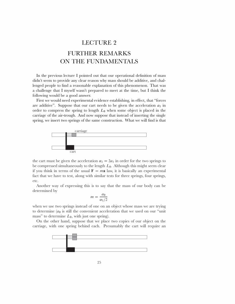
First we would need experimental evidence establishing, in e˛ect, that \forcesare additive". Suppose that our cart needs to be given the acceleration a1 inorder to compress the spring to length L0 when some object is placed in thecarriage of the air-trough. And now suppose that instead of inserting the singlespring, we insert two springs of the same construction. What we will ˇnd is that
the cart must be given the acceleration ˛1 D 2a1 in order for the two springs tobe compressed simultaneously to the length L0� Although this might seem clearif you think in terms of the usual F D ma law, it is basically an experimentalfact that we have to test, along with similar tests for three springs, four springs,etc.
Another way of expressing this is to say that the mass of our body can bedetermined by
m Da0
˛1=2
when we use two springs instead of one on an object whose mass we are tryingto determine (a0 is still the convenient acceleration that we used on our \unitmass" to determine L0� with just one spring).
On the other hand, suppose that we place two copies of our object on thecarriage, with one spring behind each. Presumably the cart will require an
25
LECTURE 2
acceleration of a1 to compress the two springs to length L0� since we can simplythink of this as two copies of the original experiment carried out side-by-side.If we now think of this as two springs behind the one object consisting of twocopies of our original object, it follows that the mass of this new object is just
a0
a1=2D 2
a0
a1D 2m�
and of course we could just as well repeat the argument for other multiples, andeventually reason our way to the general rule.
I'd also like to examine the \thought experiments" that Huygens adducedin support of conservation of momentum, not only as an interesting historicalcuriosity, but also because it connects rather closely to the whole notion of\symmetry", which gets rather abused in modern thought.
First consider two identical bodies, say two steel balls, moving toward eachother with equal speeds, i.e., with velocities v and �v� In this simple situation itis obviously reasonable to assume, on the basis of symmetry, that their reboundvelocities will also be negatives of each other, w and �w� so that conservationof momentum holds: it is 0 both before and after the collision.
Now let us imagine the same experiment as observed in a coordinate systemthat is moving with uniform velocity u with respect to us, like a boat movingwith respect to the shore, to take Huygens' example. ([M], Chapter III, sectionIV contains a reproduction of the delightfully quaint illustration that appearsin Huygens' book \De Motu Corporum ex Percussione" of 1703; this ˇgurealso appears in [Fr], which gives a fairly detailed description of the followingargument). In this coordinate system, the objects are moving with the initialvelocities
v1 D v C u and v2 D �v C u�
while their rebound velocities are
w1 D w C u and w2 D �w C u�
so v1 Cv2 D w1 Cw2 (D 2u). Since we can obtain any pair v1; v2 by choosing theappropriate u and v� we ˇnd that in the coordinate system of the boat, movinguniformly with respect to the shore, conservation of momentum holds for twoidentical bodies approaching each other with arbitrary velocities. Of course, wecould just as well interchange the role of the boat and the observer on shore, toreach the same conclusion for our observer on shore.
Rather than following the succeeding course of Huygens' arguments, we willadd some considerations from The Feynman Lectures on Physics, Volume 1[Fey]. Let's use steel cubes for convenience, and suppose that glue has beenapplied to opposing faces so that they will stick together when they meet. Sym-metry dictates that when they approach each other with the same velocity and
26
LECTURE 2
then stick together, they will end up at rest, so that conservation of momentumholds. Huygens' argument then implies that a collision with initial velocities v1
and v2 results in a \double cube" moving with velocity 12 .v1 C v2/�
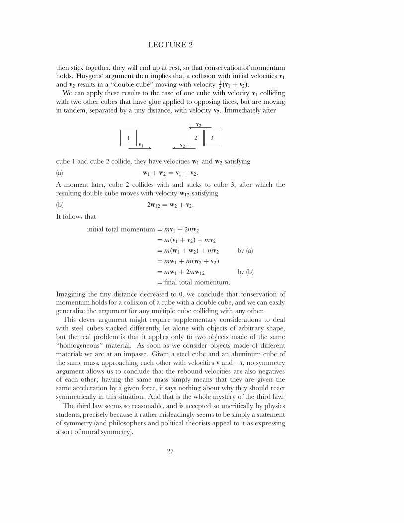
We can apply these results to the case of one cube with velocity v1 collidingwith two other cubes that have glue applied to opposing faces, but are movingin tandem, separated by a tiny distance, with velocity v2� Immediately after
cube 1 and cube 2 collide, they have velocities w1 and w2 satisfying
(a) w1 C w2 D v1 C v2:
A moment later, cube 2 collides with and sticks to cube 3� after which theresulting double cube moves with velocity w12 satisfying
(b) 2w12 D w2 C v2:
It follows that
initial total momentum D mv1 C 2mv2
D m.v1 C v2/ C mv2
D m.w1 C w2/ C mv2 by (a)D mw1 C m.w2 C v2/
D mw1 C 2mw12 by (b)D ˇnal total momentum.
Imagining the tiny distance decreased to 0� we conclude that conservation ofmomentum holds for a collision of a cube with a double cube, and we can easilygeneralize the argument for any multiple cube colliding with any other.
This clever argument might require supplementary considerations to dealwith steel cubes stacked di˛erently, let alone with objects of arbitrary shape,but the real problem is that it applies only to two objects made of the same\homogeneous" material. As soon as we consider objects made of di˛erentmaterials we are at an impasse. Given a steel cube and an aluminum cube ofthe same mass, approaching each other with velocities v and �v� no symmetryargument allows us to conclude that the rebound velocities are also negativesof each other; having the same mass simply means that they are given thesame acceleration by a given force, it says nothing about why they should reactsymmetrically in this situation. And that is the whole mystery of the third law.
The third law seems so reasonable, and is accepted so uncritically by physicsstudents, precisely because it rather misleadingly seems to be simply a statementof symmetry (and philosophers and political theorists appeal to it as expressinga sort of moral symmetry).
27
LECTURE 2
I want to conclude this lecture with one seemingly minor point about thefundamentals of mechanics that has so far been omitted. Newton's statementconcerning conservation of momentum, previously quoted, was
Corollary 3 The quantity of motion, which is determined by adding the motions made inone direction and subtracting the motions made in the opposite direction, is notchanged by the action of bodies on one another.
while Corollary 1, which we skipped, says
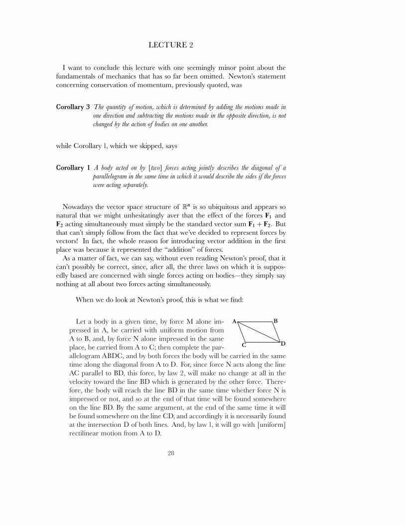
Corollary 1 A body acted on by [two] forces acting jointly describes the diagonal of aparallelogram in the same time in which it would describe the sides if the forceswere acting separately.
Nowadays the vector space structure of Rn is so ubiquitous and appears sonatural that we might unhesitatingly aver that the e˛ect of the forces F1 andF2 acting simultaneously must simply be the standard vector sum F1 C F2� Butthat can't simply follow from the fact that we've decided to represent forces byvectors! In fact, the whole reason for introducing vector addition in the ˇrstplace was because it represented the \addition" of forces.
As a matter of fact, we can say, without even reading Newton's proof, that itcan't possibly be correct, since, after all, the three laws on which it is suppos-edly based are concerned with single forces acting on bodies|they simply saynothing at all about two forces acting simultaneously.
When we do look at Newton's proof, this is what we ˇnd:
Let a body in a given time, by force M alone im-pressed in A, be carried with uniform motion fromA to B, and, by force N alone impressed in the sameplace, be carried from A to C; then complete the par-allelogram ABDC, and by both forces the body will be carried in the sametime along the diagonal from A to D. For, since force N acts along the lineAC parallel to BD, this force, by law 2, will make no change at all in thevelocity toward the line BD which is generated by the other force. There-fore, the body will reach the line BD in the same time whether force N isimpressed or not, and so at the end of that time will be found somewhereon the line BD. By the same argument, at the end of the same time it willbe found somewhere on the line CD, and accordingly it is necessarily foundat the intersection D of both lines. And, by law 1, it will go with [uniform]rectilinear motion from A to D.
28
LECTURE 2
Even before we reach any questionable steps, we see from the very ˇrst phrasesthat Newton is framing this proof in terms of impulsive forces, since he statesthat the forces M and N individually produce a uniform motion on the object.Moreover, at the very end of the argument he implicitly assumes that the combi-nation of the two impulsive forces must also be an impulsive force, so that the objectmoves with uniform motion from the initial point A to the ˇnal point D� Theremaining part of the argument is the most dubious of all, with its argumentthat the force N \will make no change at all in the velocity toward the line BD
which is generated by the other force".In defense of Newton, we ought to unveil the material that was hidden in our
original presentation of the second law:
Law 2 A change in motion is proportional to the motive force impressed and takes place alongthe straight line in which that force is impressed.
If some force generates any motion, twice the force will generate twicethe motion, : : : . And if the body was previously moving, the new mo-tion (since motion is always in the same direction as the generative force)is added to the original motion if that motion was in the same directionor is subtracted from the original motion if it was in the opposite di-rection or, if it was in an oblique direction, is combined obliquely andcompounded with it according to the directions of both motions.
This almost sounds like a statement of Corollary 1. Actually, it will also helpto go back to Newton's Scholium, and unveil the material that was deleted there,when we quoted his acknowledgment of Galileo:
Scholium The principles I have set forth are accepted by mathematicians andconˇrmed by experiments of many kinds. By means of the ˇrst twolaws and the [ˇrst corollary] Galileo found that the descent of heavybodies is in the squared ratio of the time and that the motion of pro-jectiles occurs in a parabola, as experiment conˇrms, except insofaras these motions are somewhat retarded by the resistance of the air.
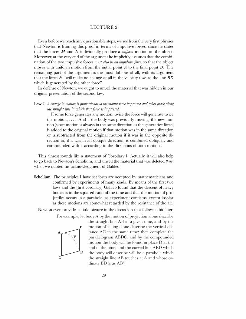
Newton even provides a little picture in the discussion that follows a bit later:For example, let body A by the motion of projection alone describe
the straight line AB in a given time, and by themotion of falling alone describe the vertical dis-tance AC in the same time; then complete theparallelogram ABDC, and by the compoundedmotion the body will be found in place D at theend of the time; and the curved line AED whichthe body will describe will be a parabola whichthe straight line AB touches at A and whose or-dinate BD is as AB2�
29
LECTURE 2
Here, of course, we are considering, on the one hand, an impulsive force,which gives the object its uniform horizontal motion, and, on the other hand,the force of gravity, which gives the object its non-uniform vertical motion. Andindeed this really illustrates only that the action of a force on an object is inde-pendent of the object's uniform velocity, which was Galileo's basic observation.
Basically, Newton is saying that Corollary 1 holds if we think of one of the twoforces having already been applied, and then trying to sucker us into concludingthat it holds when they are applied simultaneously. Of course, from a modernquantum mechanical point of view this might seem extremely reasonable, be-cause the each force is presumed to come about by interactions with myriadspecial particles, and one could ignore the inˇnitesimal probability of two suchinteractions occuring exactly at the same time.
But if we stick to the classical picture, then from a strictly logical point of view,it is not even clear that two forces F1 and F2 acting simultaneously should havethe same e˛ect as any other single force F: while it's true that the combinedforces must end up producing an acceleration of some sort on each object, thatacceleration might not be proportional to the mass of the object, even thoughthe accelerations produced by F1 and F2 individually are.
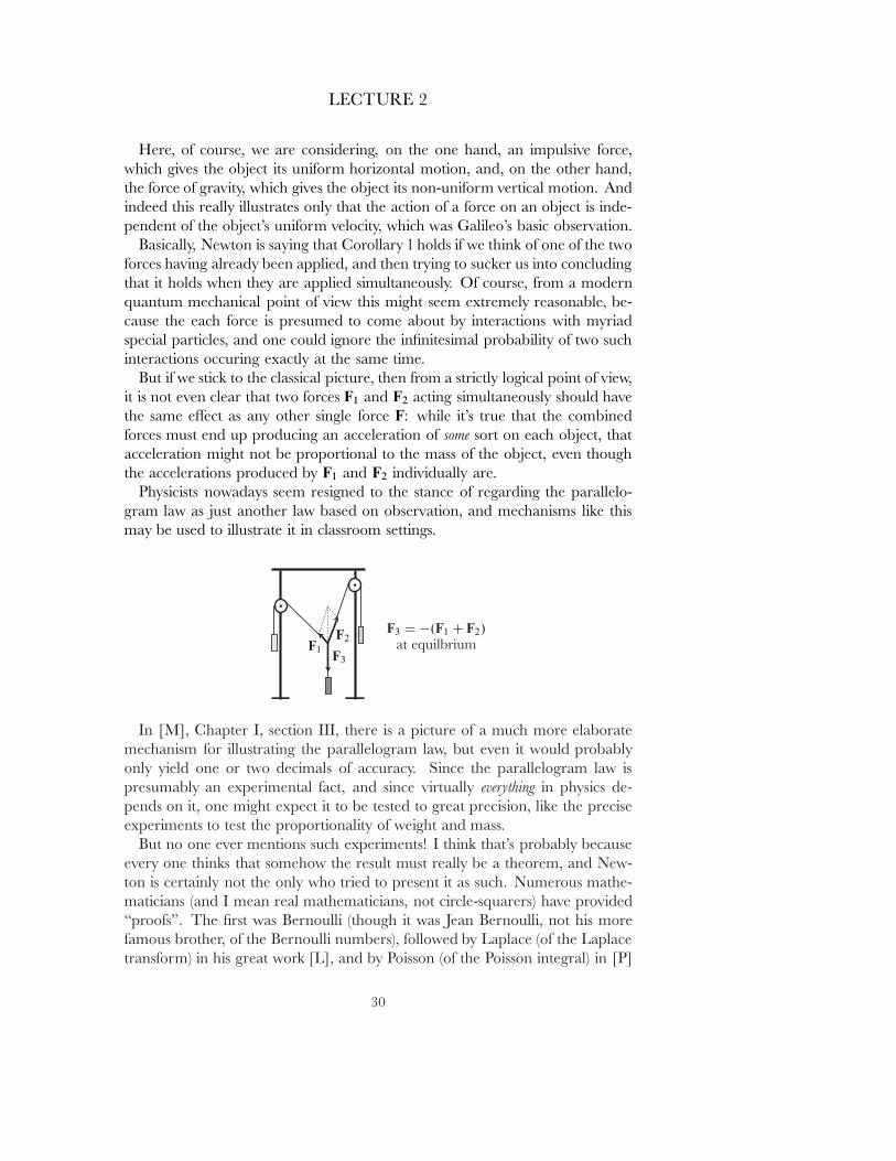
Physicists nowadays seem resigned to the stance of regarding the parallelo-gram law as just another law based on observation, and mechanisms like thismay be used to illustrate it in classroom settings.
In [M], Chapter I, section III, there is a picture of a much more elaboratemechanism for illustrating the parallelogram law, but even it would probablyonly yield one or two decimals of accuracy. Since the parallelogram law ispresumably an experimental fact, and since virtually everything in physics de-pends on it, one might expect it to be tested to great precision, like the preciseexperiments to test the proportionality of weight and mass.
But no one ever mentions such experiments! I think that's probably becauseevery one thinks that somehow the result must really be a theorem, and New-ton is certainly not the only who tried to present it as such. Numerous mathe-maticians (and I mean real mathematicians, not circle-squarers) have provided\proofs". The ˇrst was Bernoulli (though it was Jean Bernoulli, not his morefamous brother, of the Bernoulli numbers), followed by Laplace (of the Laplacetransform) in his great work [L], and by Poisson (of the Poisson integral) in [P]
30
LECTURE 2
and by Hamilton (of Hamiltonian mechanics and the Hamilton-Jacobi equa-tion) in [H].
If you try to read these proofs|supposedly mathematical proofs of a non-mathematical fact|you will see that they are all shrouded in a somewhat im-penetrable veil of unstated assumptions, making it all the harder to read them,and of course in those days even mathematical results were stated in strangeways, and the proofs are nowadays hard to read. Since the proofs, no matterhow complicated, or how elegant, all share the same fatal aws, I'll give prideof place to Bernoulli's proof, and present the main idea, based on the accountin [M] (not bothering with some details, since the only point of presenting it isto demolish it).
We restrict our considerations to R2 � so that we are only treating forces inone plane. As we have already indicated, the ˇrst basic assumption is that twoforces v; w acting together have the same e˛ect as some other force. Thus, weare assuming that for each pair v; w 2 R2 we have another element v ˚ w 2 R2�
We presumably shouldn't object to assuming that v ˚ w D w ˚ v� and also thatv ˚ v D 2v (an equation inherent in the very discussion at the beginning ofthis lecture). More generally, of course, we could assume that any k-fold sumv ˚� � �˚ v makes sense, and has the value kv� without worrying about the orderin which the operations ˚ are performed, but for the moment we will leaveaside the question of what other assumptions would be reasonable. Our goal isto show that v ˚ w is simply the usual vector sum v C w�
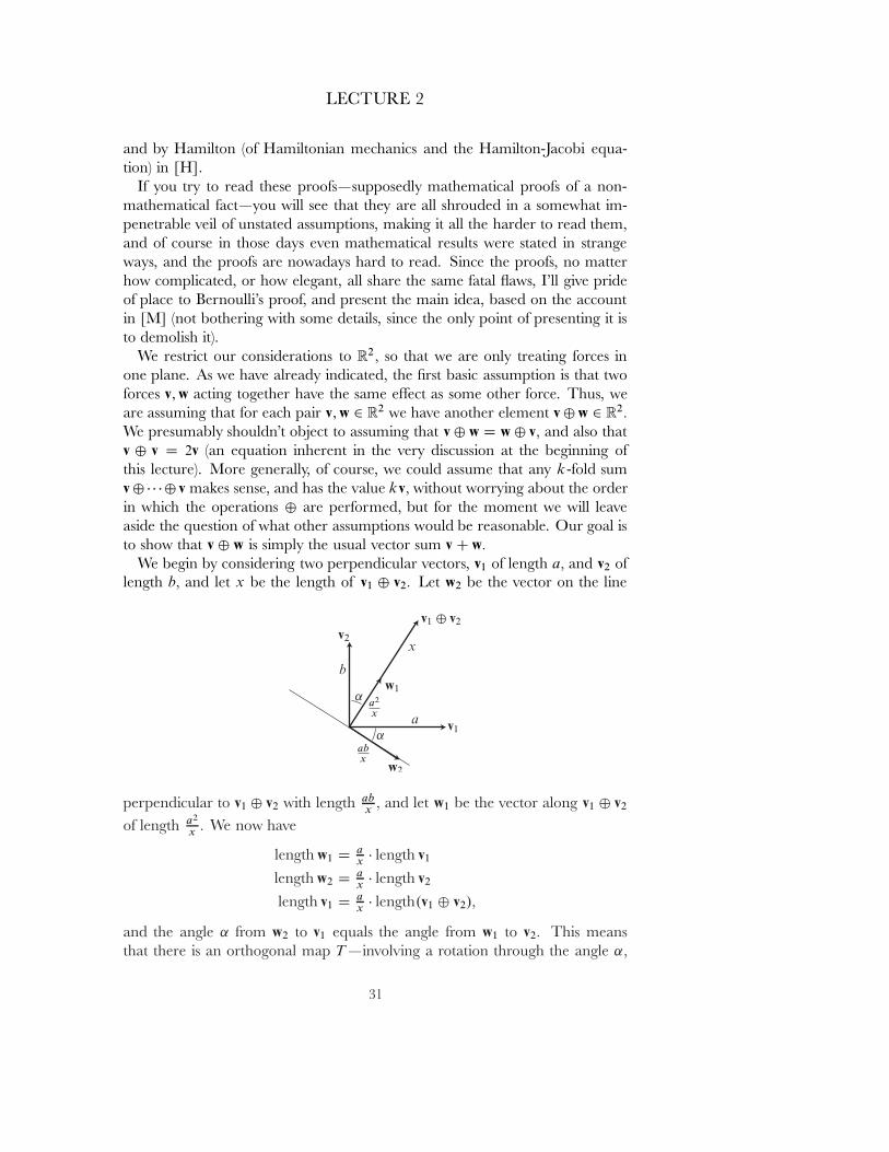
We begin by considering two perpendicular vectors, v1 of length a� and v2 oflength b� and let x be the length of v1 ˚ v2� Let w2 be the vector on the line
perpendicular to v1 ˚ v2 with length abx
� and let w1 be the vector along v1 ˚ v2
of length a2
x� We now have
length w1 D ax
� length v1
length w2 D ax
� length v2
length v1 D ax
� length.v1 ˚ v2/�
and the angle ˛ from w2 to v1 equals the angle from w1 to v2� This meansthat there is an orthogonal map T |involving a rotation through the angle ˛�
31
LECTURE 2
together with a re ection|such that
ax
T .v1/ D w1
ax
T .v2/ D w2
ax
T .v1 ˚ v2/ D v1:
From this we conclude that
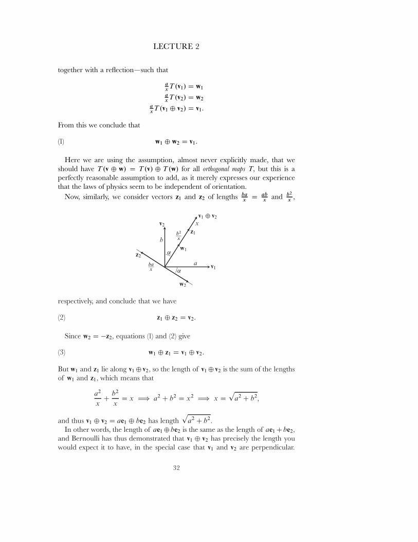
(1) w1 ˚ w2 D v1:
Here we are using the assumption, almost never explicitly made, that weshould have T .v ˚ w/ D T .v/ ˚ T .w/ for all orthogonal maps T� but this is aperfectly reasonable assumption to add, as it merely expresses our experiencethat the laws of physics seem to be independent of orientation.
Now, similarly, we consider vectors z1 and z2 of lengths bax
D abx
and b2
x�
respectively, and conclude that we have
(2) z1 ˚ z2 D v2:
Since w2 D �z2� equations (1) and (2) give
(3) w1 ˚ z1 D v1 ˚ v2:
But w1 and z1 lie along v1 ˚ v2� so the length of v1 ˚ v2 is the sum of the lengthsof w1 and z1� which means that
a2
xC
b2
xD x H) a2 C b2 D x2 H) x D
pa2 C b2�
and thus v1 ˚ v2 D ae1 ˚ be2 has lengthp
a2 C b2�
In other words, the length of ae1 ˚be2 is the same as the length of ae1 Cbe2�
and Bernoulli has thus demonstrated that v1 ˚ v2 has precisely the length youwould expect it to have, in the special case that v1 and v2 are perpendicular.
32
LECTURE 2
He then proceeds by involved arguments to prove the complete result, for thegeneral case.
The one point that is usually ignored is that in our quick trip from equations(1)-(2) to (3), we had to use associativity of ˚� which is likewise used in all theother proofs that have been fashioned. But if we assume associativity of ˚� theneverything is essentially trivial: Consider the map
.a; b/ D ae1 C be2 7�! ae1 ˚ be2:
If ˚ is associative then this map will be linear. But it takes e1 to e1 and e2 to e2�
so it must be the identity. Q.E.D.
So in the end, I really don't know what to say about the parallelogram law.I think we do have to resort to the modern view that it is an experimental fact,and then just wonder why no one has ever done an experiment to test it!
33
LECTURE 3
HOW NEWTON ANALYZEDPLANETARY MOTION
After the \Deˇnitions" and \Axioms" sections of the Principia, we get toBook 1, \The Motion of Bodies". This begins with a preliminary section thatbasically treats elements of calculus in a geometric guise, and then Newton im-mediately starts the next section with \Kepler's second law", though he doesn'tmention Kepler's name.
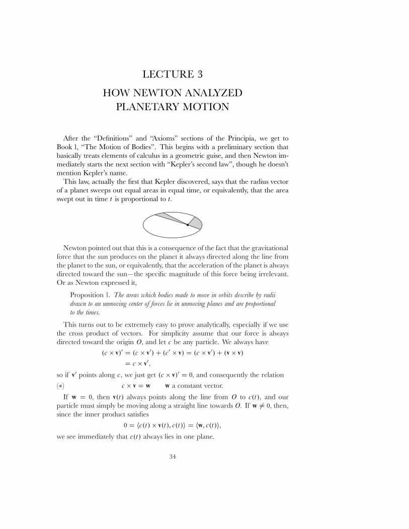
This law, actually the ˇrst that Kepler discovered, says that the radius vectorof a planet sweeps out equal areas in equal time, or equivalently, that the areaswept out in time t is proportional to t�
Newton pointed out that this is a consequence of the fact that the gravitationalforce that the sun produces on the planet it always directed along the line fromthe planet to the sun, or equivalently, that the acceleration of the planet is alwaysdirected toward the sun|the speciˇc magnitude of this force being irrelevant.Or as Newton expressed it,
Proposition 1. The areas which bodies made to move in orbits describe by radiidrawn to an unmoving center of forces lie in unmoving planes and are proportionalto the times.
This turns out to be extremely easy to prove analytically, especially if we usethe cross product of vectors. For simplicity assume that our force is alwaysdirected toward the origin O� and let c be any particle. We always have
.c � v/0 D .c � v0/ C .c0 � v/ D .c � v0/ C .v � v/
D c � v0�
so if v0 points along c� we just get .c � v/0 D 0� and consequently the relation(�) c � v D w w a constant vector.
If w D 0� then v.t/ always points along the line from O to c.t/� and ourparticle must simply be moving along a straight line towards O� If w 6D 0� then,since the inner product satisˇes
0 D hc.t/ � v.t/; c.t/i D hw; c.t/i�we see immediately that c.t/ always lies in one plane.
34
LECTURE 3
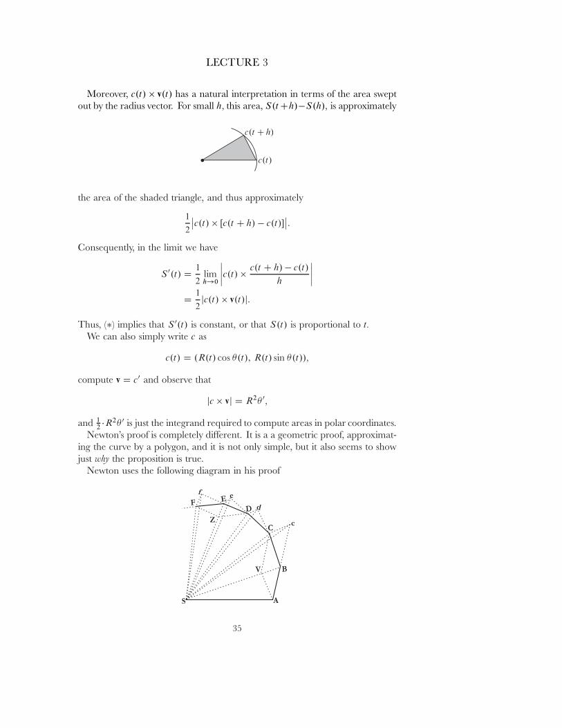
Moreover, c.t/ � v.t/ has a natural interpretation in terms of the area sweptout by the radius vector. For small h� this area, S.t Ch/�S.h/� is approximately
the area of the shaded triangle, and thus approximately
1
2
ˇc.t/ � Œc.t C h/ � c.t/�
ˇ:
Consequently, in the limit we have
S 0.t/ D1
2limh!0
ˇˇc.t/ �
c.t C h/ � c.t/
h
ˇˇ
D1
2jc.t/ � v.t/j:
Thus, (�) implies that S 0.t/ is constant, or that S.t/ is proportional to t�
We can also simply write c as
c.t/ D .R.t/ cos �.t/; R.t/ sin �.t//�
compute v D c0 and observe that
jc � vj D R2� 0�
and 12 �R2� 0 is just the integrand required to compute areas in polar coordinates.
Newton's proof is completely di˛erent. It is a a geometric proof, approximat-ing the curve by a polygon, and it is not only simple, but it also seems to showjust why the proposition is true.
Newton uses the following diagram in his proof
35

LECTURE 3
but we only need to consider a small portion of it:
Newton assumes that the particle follows the path ABCD : : : � receiving \im-pulsive" forces at short equal intervals of time, and that these impulsive forcesat B� C� : : : are always directed toward S� so that the path sweeps out the tri-angular areas 4SAB� 4SBC� : : : . Newton merely has to point out that, if notfor the impulsive force at B� the particle would move to c� with Bc D AB� Inthis case, it would sweep out the triangle 4SBc� which has the same area as4SAB (since they have equal bases, and the same height). The impulsive forceapplied at B will instead send the particle to C� which will be at the diagonalof the parallelogram formed by Bc and a line BV pointing along SB� since weare assuming that the force is directed toward S� This means that Cc is parallelto BV� and this in turn means that 4SBc has the same area as 4SBC (sincethese triangles have the common base SB and the same height above that base).In short, the area of 4SAB is the same as the area of 4SBC� and so on, allalong the path!
It is also noteworthy that Newton expressly states the converse of Proposition 1(the proof being pretty much the same):
Proposition 2. Every body that moves in some curved line described in a planeand, by a radius drawn to a point, : : : describes areas around that point proportionalto the times, is urged by a centripetal force tending toward that same point.
Newton's proof of Kepler's second law is sometimes presented in elementaryphysics books, but then we are told that the rest of Newton's arguments won'tbe given because they require many abstruse properties of conic sections whichare unfamiliar to us nowadays. But this is rather insincere. While it is quiteunderstandable that a geometric proof would use many geometric properties ofconics, the real mystery is how an hypothesis about inverse square forces is goingto be related to geometric properties of conic sections. Moreover, although wewon't pursue Newton's argument in its entirety, it turns out that Newton's strate�for the proof is extremely clever, far too clever for most of his contemporaries(and even for some people today).
36
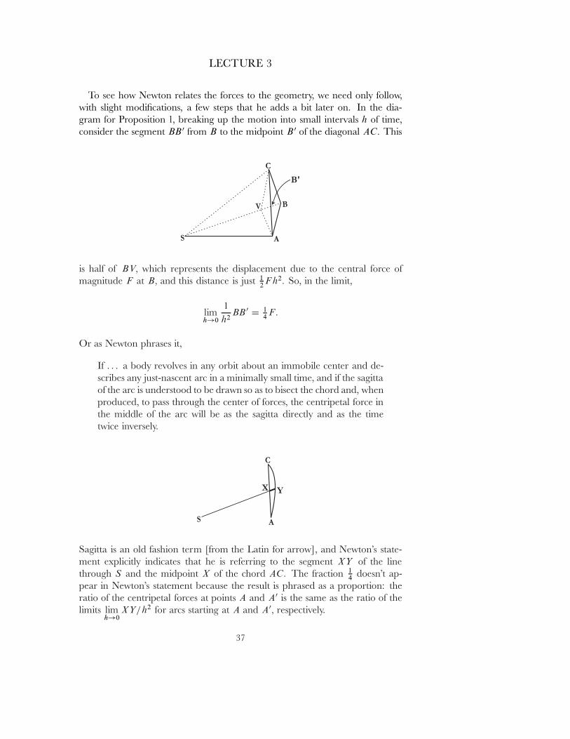
LECTURE 3
To see how Newton relates the forces to the geometry, we need only follow,with slight modiˇcations, a few steps that he adds a bit later on. In the dia-gram for Proposition 1, breaking up the motion into small intervals h of time,consider the segment BB 0 from B to the midpoint B 0 of the diagonal AC� This
is half of BV� which represents the displacement due to the central force ofmagnitude F at B� and this distance is just 1
2 Fh2� So, in the limit,
limh!0
1
h2BB 0 D 1
4 F:
Or as Newton phrases it,
If : : : a body revolves in any orbit about an immobile center and de-scribes any just-nascent arc in a minimally small time, and if the sagittaof the arc is understood to be drawn so as to bisect the chord and, whenproduced, to pass through the center of forces, the centripetal force inthe middle of the arc will be as the sagitta directly and as the timetwice inversely.
Sagitta is an old fashion term [from the Latin for arrow], and Newton's state-ment explicitly indicates that he is referring to the segment XY of the linethrough S and the midpoint X of the chord AC� The fraction 1
4 doesn't ap-pear in Newton's statement because the result is phrased as a proportion: theratio of the centripetal forces at points A and A0 is the same as the ratio of thelimits lim
h!0XY=h2 for arcs starting at A and A0� respectively.
37
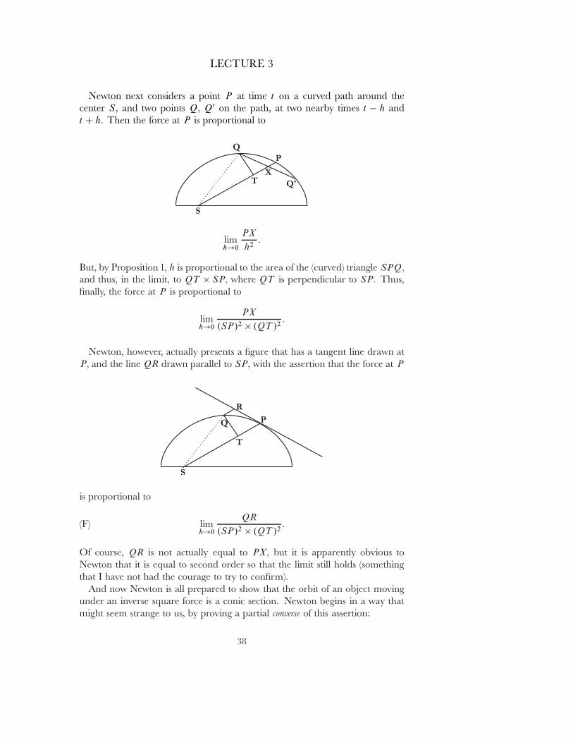
LECTURE 3
Newton next considers a point P at time t on a curved path around thecenter S� and two points Q� Q0 on the path, at two nearby times t � h andt C h� Then the force at P is proportional to
limh!0
PX
h2:
But, by Proposition 1, h is proportional to the area of the (curved) triangle SPQ�
and thus, in the limit, to QT � SP� where QT is perpendicular to SP� Thus,ˇnally, the force at P is proportional to
limh!0
PX
.SP/2 � .QT /2:
Newton, however, actually presents a ˇgure that has a tangent line drawn atP� and the line QR drawn parallel to SP� with the assertion that the force at P
is proportional to
(F) limh!0
QR
.SP/2 � .QT /2:
Of course, QR is not actually equal to PX� but it is apparently obvious toNewton that it is equal to second order so that the limit still holds (somethingthat I have not had the courage to try to conˇrm).
And now Newton is all prepared to show that the orbit of an object movingunder an inverse square force is a conic section. Newton begins in a way thatmight seem strange to us, by proving a partial converse of this assertion:
38
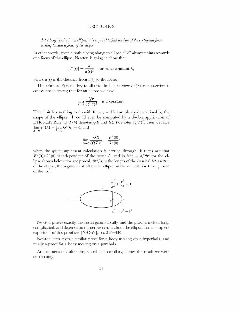
LECTURE 3
Let a body revolve in an ellipse; it is required to ˇnd the law of the centripetal forcetending toward a focus of the ellipse.
In other words, given a path c lying along an ellipse, if c00 always points towardsone focus of the ellipse, Newton is going to show that
jc00.t/j Dk
d.t/2for some constant k�
where d.t/ is the distance from c.t/ to the focus.The relation (F) is the key to all this. In fact, in view of (F), our assertion is
equivalent to saying that for an ellipse we have
limh!0
QR
.QT /2is a constant.
This limit has nothing to do with forces, and is completely determined by theshape of the ellipse. It could even be computed by a double application ofL'Hopital's Rule: If F.h/ denotes QR and G.h/ denotes .QT /2� then we havelimh!0
F 0.h/ D limh!0
G 0.h/ D 0� and
limh!0
QR
.QT /2D
F 00.0/
G 00.0/;
when the quite unpleasant calculation is carried through, it turns out thatF 00.0/=G 00.0/ is independent of the point P� and in fact D a=2b2 for the el-lipse shown below; the reciprocal, 2b2=a� is the length of the classical latus rectumof the ellipse, the segment cut o˛ by the ellipse on the vertical line through oneof the foci.
Newton proves exactly this result geometrically, and the proof is indeed long,complicated, and depends on numerous results about the ellipse. For a completeexposition of this proof see [N-C-W], pp. 325{330.
Newton then gives a similar proof for a body moving on a hyperbola, andˇnally a proof for a body moving on a parabola.
And immediately after this, stated as a corollary, comes the result we wereanticipating:
39
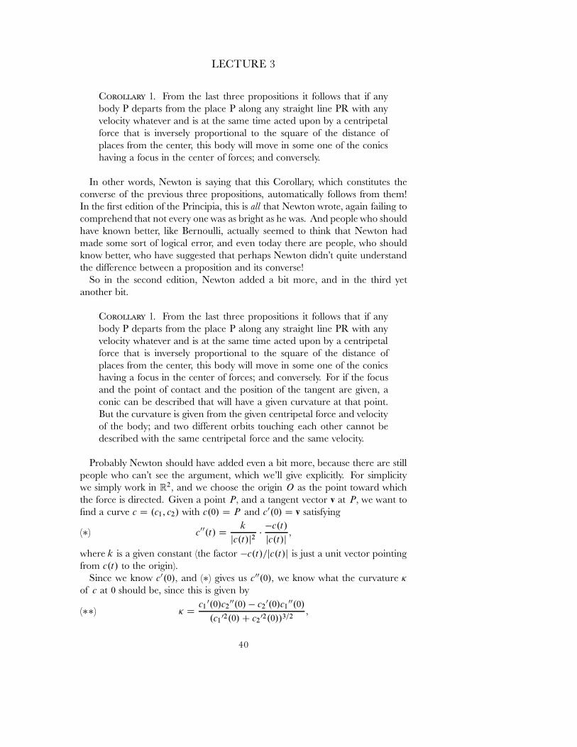
LECTURE 3
COROLLARY 1. From the last three propositions it follows that if anybody P departs from the place P along any straight line PR with anyvelocity whatever and is at the same time acted upon by a centripetalforce that is inversely proportional to the square of the distance ofplaces from the center, this body will move in some one of the conicshaving a focus in the center of forces; and conversely.
In other words, Newton is saying that this Corollary, which constitutes theconverse of the previous three propositions, automatically follows from them!In the ˇrst edition of the Principia, this is all that Newton wrote, again failing tocomprehend that not every one was as bright as he was. And people who shouldhave known better, like Bernoulli, actually seemed to think that Newton hadmade some sort of logical error, and even today there are people, who shouldknow better, who have suggested that perhaps Newton didn't quite understandthe di˛erence between a proposition and its converse!
So in the second edition, Newton added a bit more, and in the third yetanother bit.
COROLLARY 1. From the last three propositions it follows that if anybody P departs from the place P along any straight line PR with anyvelocity whatever and is at the same time acted upon by a centripetalforce that is inversely proportional to the square of the distance ofplaces from the center, this body will move in some one of the conicshaving a focus in the center of forces; and conversely. For if the focusand the point of contact and the position of the tangent are given, aconic can be described that will have a given curvature at that point.But the curvature is given from the given centripetal force and velocityof the body; and two di˛erent orbits touching each other cannot bedescribed with the same centripetal force and the same velocity.
Probably Newton should have added even a bit more, because there are stillpeople who can't see the argument, which we'll give explicitly. For simplicitywe simply work in R2� and we choose the origin O as the point toward whichthe force is directed. Given a point P� and a tangent vector v at P� we want toˇnd a curve c D .c1; c2/ with c.0/ D P and c0.0/ D v satisfying
(�) c00.t/ Dk
jc.t/j2�
�c.t/
jc.t/j�
where k is a given constant (the factor �c.t/=jc.t/j is just a unit vector pointingfrom c.t/ to the origin).
Since we know c0.0/� and (�) gives us c00.0/� we know what the curvature �
of c at 0 should be, since this is given by
(��) � Dc1
0.0/c200.0/ � c2
0.0/c100.0/
.c102.0/ C c2
02.0//3=2�
40
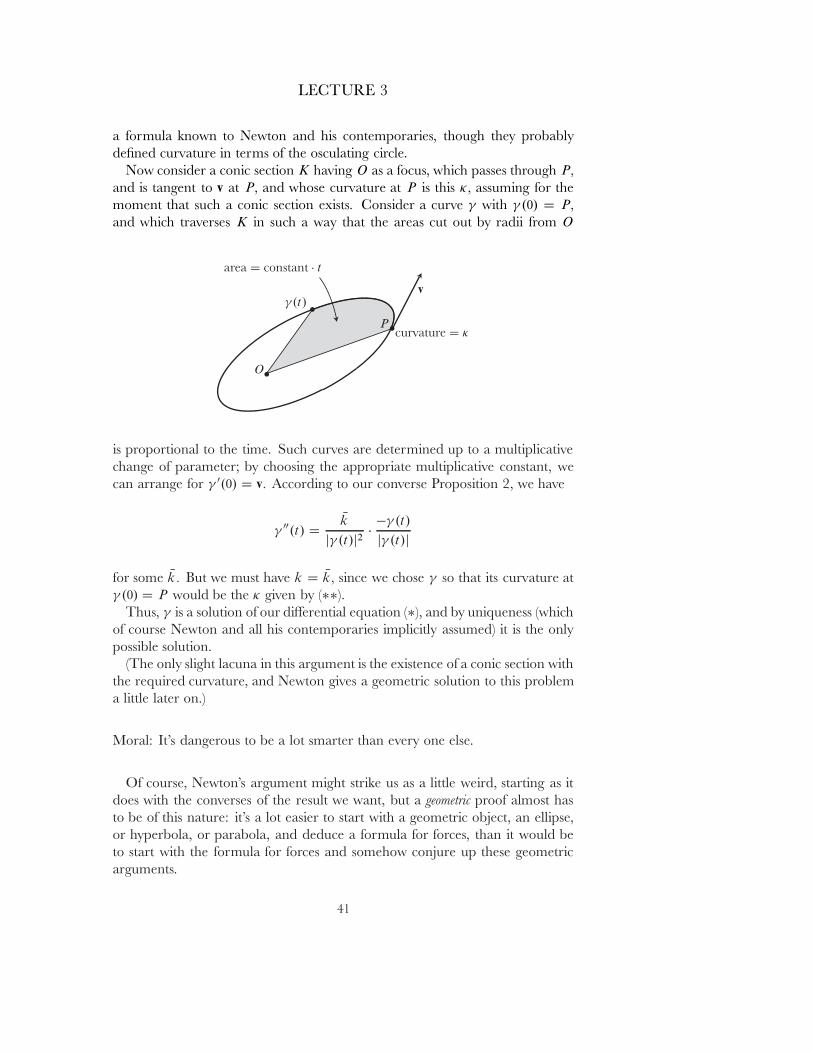
LECTURE 3
a formula known to Newton and his contemporaries, though they probablydeˇned curvature in terms of the osculating circle.
Now consider a conic section K having O as a focus, which passes through P�
and is tangent to v at P� and whose curvature at P is this �� assuming for themoment that such a conic section exists. Consider a curve with .0/ D P�
and which traverses K in such a way that the areas cut out by radii from O
is proportional to the time. Such curves are determined up to a multiplicativechange of parameter; by choosing the appropriate multiplicative constant, wecan arrange for 0.0/ D v� According to our converse Proposition 2, we have
00.t/ DNk
j .t/j2�
� .t/
j .t/j
for some Nk� But we must have k D Nk� since we chose so that its curvature at .0/ D P would be the � given by (��).
Thus, is a solution of our di˛erential equation (�), and by uniqueness (whichof course Newton and all his contemporaries implicitly assumed) it is the onlypossible solution.
(The only slight lacuna in this argument is the existence of a conic section withthe required curvature, and Newton gives a geometric solution to this problema little later on.)
Moral: It's dangerous to be a lot smarter than every one else.
Of course, Newton's argument might strike us as a little weird, starting as itdoes with the converses of the result we want, but a geometric proof almost hasto be of this nature: it's a lot easier to start with a geometric object, an ellipse,or hyperbola, or parabola, and deduce a formula for forces, than it would beto start with the formula for forces and somehow conjure up these geometricarguments.
41
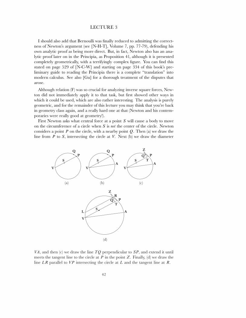
LECTURE 3
I should also add that Bernoulli was ˇnally reduced to admitting the correct-ness of Newton's argument (see [N-H-T], Volume 7, pp. 77-79), defending hisown analytic proof as being more direct. But, in fact, Newton also has an ana-lytic proof later on in the Principia, as Proposition 41, although it is presentedcompletely geometrically, with a terrifyingly complex ˇgure. You can ˇnd thisstated on page 529 of [N-C-W] and starting on page 334 of this book's pre-liminary guide to reading the Principia there is a complete \translation" intomodern calculus. See also [Gu] for a thorough treatment of the disputes thatarose.
Although relation (F) was so crucial for analyzing inverse square forces, New-ton did not immediately apply it to that task, but ˇrst showed other ways inwhich it could be used, which are also rather interesting. The analysis is purelygeometric, and for the remainder of this lecture you may think that you're backin geometry class again, and a really hard one at that (Newton and his contem-poraries were really good at geometry!).
First Newton asks what central force at a point S will cause a body to moveon the circumference of a circle when S is not the center of the circle. Newtonconsiders a point P on the circle, with a nearby point Q� Then (a) we draw theline from P to S� intersecting the circle at V� Next (b) we draw the diameter
VA� and then (c) we draw the line TQ perpendicular to SP� and extend it untilmeets the tangent line to the circle at P in the point Z� Finally, (d) we draw theline LR parallel to VP intersecting the circle at L and the tangent line at R�
42
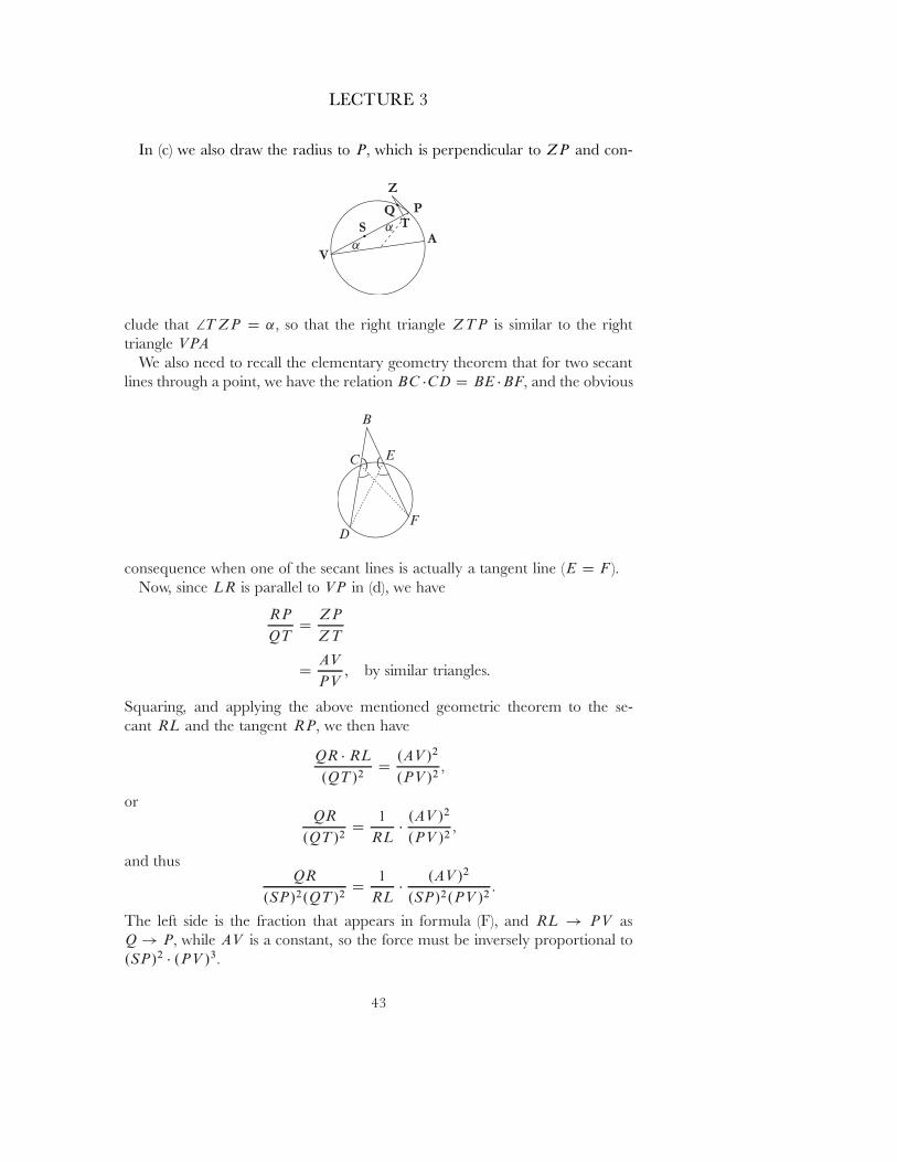
LECTURE 3
In (c) we also draw the radius to P� which is perpendicular to ZP and con-
clude that 2T ZP D ˛� so that the right triangle ZTP is similar to the righttriangle VPA
We also need to recall the elementary geometry theorem that for two secantlines through a point, we have the relation BC �CD D BE �BF� and the obvious
consequence when one of the secant lines is actually a tangent line (E D F ).Now, since LR is parallel to VP in (d), we have
RP
QTD
ZP
ZT
DAV
PV, by similar triangles.
Squaring, and applying the above mentioned geometric theorem to the se-cant RL and the tangent RP� we then have
QR � RL
.QT /2D
.AV /2
.PV /2�
orQR
.QT /2D
1
RL�
.AV /2
.PV /2�
and thusQR
.SP/2.QT /2D
1
RL�
.AV /2
.SP/2.PV /2:
The left side is the fraction that appears in formula (F), and RL ! PV asQ ! P� while AV is a constant, so the force must be inversely proportional to.SP/2 � .PV /3�
43
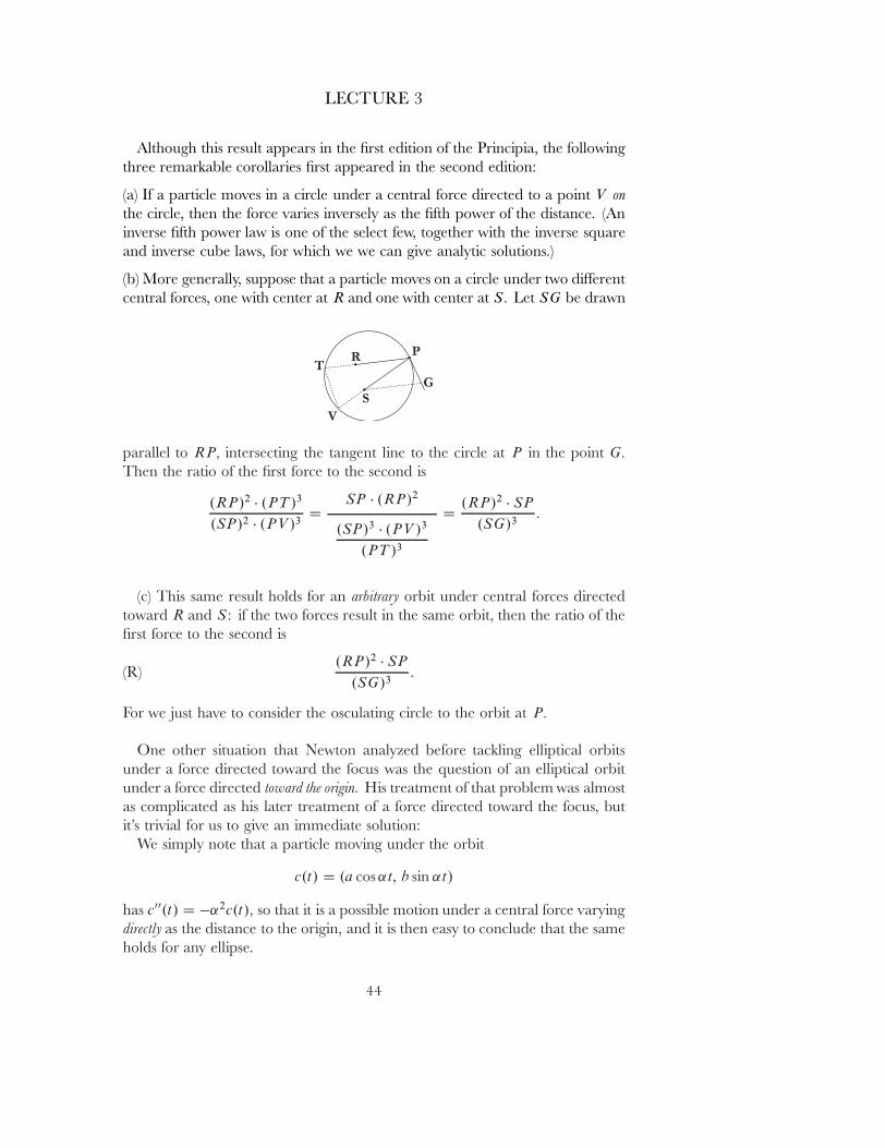
LECTURE 3
Although this result appears in the ˇrst edition of the Principia, the followingthree remarkable corollaries ˇrst appeared in the second edition:
(a) If a particle moves in a circle under a central force directed to a point V onthe circle, then the force varies inversely as the ˇfth power of the distance. (Aninverse ˇfth power law is one of the select few, together with the inverse squareand inverse cube laws, for which we we can give analytic solutions.)
(b) More generally, suppose that a particle moves on a circle under two di˛erentcentral forces, one with center at R and one with center at S� Let SG be drawn
parallel to RP� intersecting the tangent line to the circle at P in the point G�
Then the ratio of the ˇrst force to the second is
.RP/2 � .PT /3
.SP/2 � .PV /3D
SP � .RP/2
.SP/3 � .PV /3
.PT /3
D.RP/2 � SP
.SG/3:
(c) This same result holds for an arbitrary orbit under central forces directedtoward R and S : if the two forces result in the same orbit, then the ratio of theˇrst force to the second is
(R).RP/2 � SP
.SG/3:
For we just have to consider the osculating circle to the orbit at P�
One other situation that Newton analyzed before tackling elliptical orbitsunder a force directed toward the focus was the question of an elliptical orbitunder a force directed toward the origin. His treatment of that problem was almostas complicated as his later treatment of a force directed toward the focus, butit's trivial for us to give an immediate solution:
We simply note that a particle moving under the orbit
c.t/ D .a cos ˛t; b sin ˛t/
has c00.t/ D �˛2c.t/� so that it is a possible motion under a central force varyingdirectly as the distance to the origin, and it is then easy to conclude that the sameholds for any ellipse.
44
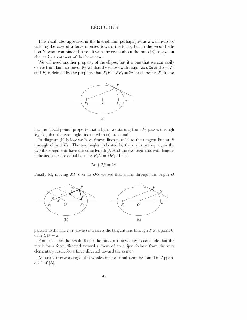
LECTURE 3
This result also appeared in the ˇrst edition, perhaps just as a warm-up fortackling the case of a force directed toward the focus, but in the second edi-tion Newton combined this result with the result about the ratio (R) to give analternative treatment of the focus case.
We will need another property of the ellipse, but it is one that we can easilyderive from familiar ones. Recall that the ellipse with major axis 2a and foci F1
and F2 is deˇned by the property that F1P C PF2 D 2a for all points P� It also
has the \focal point" property that a light ray starting from F1 passes throughF2� i.e., that the two angles indicated in (a) are equal.
In diagram (b) below we have drawn lines parallel to the tangent line at P
through O and F2� The two angles indicated by thick arcs are equal, so thetwo thick segments have the same length ˇ� And the two segments with lengthsindicated as ˛ are equal because F1O D OF2� Thus
2˛ C 2ˇ D 2a:
Finally (c), moving XP over to OG we see that a line through the origin O
parallel to the line F1P always intersects the tangent line through P at a point G
with OG D a�
From this and the result (R) for the ratio, it is now easy to conclude that theresult for a force directed toward a focus of an ellipse follows from the veryelementary result for a force directed toward the center.
An analytic reworking of this whole circle of results can be found in Appen-dix 1 of [A].
45
LECTURE 4
SYSTEMS OF PARTICLES£CONSERVATION LAWS
This lecture is fairly straightforward, and serves mainly as a prelude for thenext, when we ˇnally get to consider rigid bodies.
We will be considering a \system of particles". This means that we havecertain particles c1; : : : cK : R ! R3� with positive masses m1; : : : ; mK 2 R� Wealso have certain forces, functions
Fei : R ! R3�
the \external" forces on the particles (for example the force of gravity for asystem of particles near the earth), as well as \internal forces"
Fij D �Fji : R ! R3�
where Fij represents the force exerted by cj on ci � In accordance with the thirdlaw we are assuming that
Fij D �Fji :
In addition, we will soon need the \strong version" of the third law, which saysthat Fij points from ci to cj � i.e., Fij is a multiple of ci � cj � This strongerversion of the third law is never stated by Newton, although one might assumethat he considered this implicit, on symmetry grounds.
Finally, if we setFi D Fe
i CX
j
Fij �
so that Fi is the total force on the particle ci at time t� then we assume, inaccordance with the second law, that
Fi D mi � ci00:
The short demonstration in Lecture 1 of conservation of momentum involvedjust 2 particles and only the internal forces between them, but we can easily statea generalization for an arbitrary system of particles with external forces. If weset F D
Pi Fe
i � the total external force, then
F D�X
i
mi � vi
�0:
46
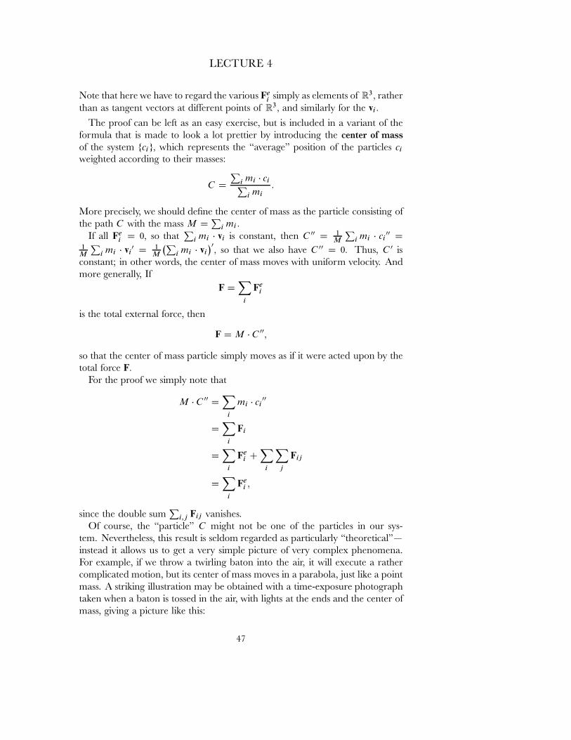
LECTURE 4
Note that here we have to regard the various Fei simply as elements of R3� rather
than as tangent vectors at di˛erent points of R3� and similarly for the vi�
The proof can be left as an easy exercise, but is included in a variant of theformula that is made to look a lot prettier by introducing the center of mass
of the system fcig� which represents the \average" position of the particles ci
weighted according to their masses:
C DP
i mi � ciPi mi
:
More precisely, we should deˇne the center of mass as the particle consisting ofthe path C with the mass M D
Pi mi �
If all Fei D 0� so that
Pi mi � vi is constant, then C 00 D 1
M
Pi mi � ci
00 D1
M
Pi mi � vi
0 D 1M
�Pi mi � vi
�0� so that we also have C 00 D 0� Thus, C 0 is
constant; in other words, the center of mass moves with uniform velocity. Andmore generally, If
F DX
i
Fei
is the total external force, then
F D M � C 00�
so that the center of mass particle simply moves as if it were acted upon by thetotal force F�
For the proof we simply note that
M � C 00 DX
i
mi � ci00
DX
i
Fi
DX
i
Fei C
X
i
X
j
Fij
DX
i
Fei �
since the double sumP
i;j Fij vanishes.Of course, the \particle" C might not be one of the particles in our sys-
tem. Nevertheless, this result is seldom regarded as particularly \theoretical"|instead it allows us to get a very simple picture of very complex phenomena.For example, if we throw a twirling baton into the air, it will execute a rathercomplicated motion, but its center of mass moves in a parabola, just like a pointmass. A striking illustration may be obtained with a time-exposure photographtaken when a baton is tossed in the air, with lights at the ends and the center ofmass, giving a picture like this:
47
LECTURE 4
By the way, we usually think of a rod as a \rigid body", and that might seemto make the above equation even more impressive: in a real rod, with all sortsof complicated intermolecular forces, which make it approximately \rigid", butnot truly so, it is still true that the center of mass moves according to a simple law.But that is a somewhat misleading way of construing the result, since rigidity ofthe rod is required in order to identify its center of mass with a particular pointof the rod, on which we can attach one of the lights.
Newton has a statement of this result as Corollary 4 in his \Axioms" section,but he uses the older term \center of gravity" for \center of mass".
The common center of gravity of two or more bodies does not change its state whether ofmotion or of rest as a result of the actions of the bodies upon one another; and thereforethe common center of gravity of all bodies acting upon one another (excluding externalactions and impediments) either is at rest or moves uniformly straight forward.
Notice that Newton explicitly disallows non-zero external forces, thereby fore-going the real interest of the corollary. Moreover, his proof is unbelievably com-plicated, occupying nearly two pages, referring in addition to a later Lemmathat occurs in a completely di˛erent context and involves a strangely compli-cated ˇgure.
I'm not sure what this all means, except perhaps that simple vector calculusis a lot more convenient than geometry. That is certainly illustrated by a secondconservation law, which occurs only implicitly in the Principia.
The cross-product �� which was used at the beginning of the previous lec-ture basically as a convenient abbreviation for manipulations with determinants,turns out to have a fundamental role in mechanics. Of course, students alwayswonder why there should be a vector product in 3 dimensions, but not in otherdimensions, and every professor seems to have their own answer. I'm going togive my answer now, and even if you don't like this particular answer, at least itwill introduce an important fact.
48
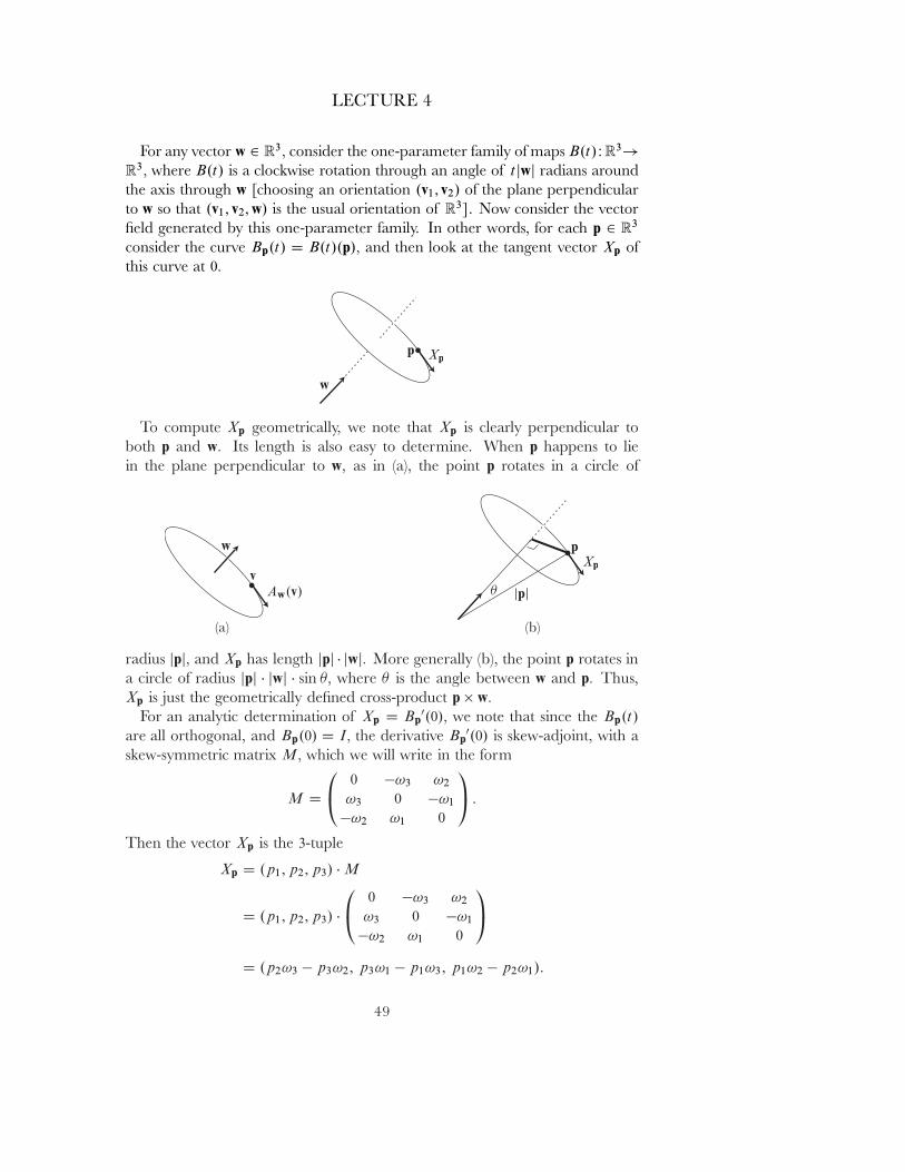
LECTURE 4
For any vector w 2 R3� consider the one-parameter family of maps B.t/: R3!R3� where B.t/ is a clockwise rotation through an angle of t jwj radians aroundthe axis through w [choosing an orientation .v1; v2/ of the plane perpendicularto w so that .v1; v2; w/ is the usual orientation of R3]. Now consider the vectorˇeld generated by this one-parameter family. In other words, for each p 2 R3
consider the curve Bp.t/ D B.t/.p/� and then look at the tangent vector Xp ofthis curve at 0�
To compute Xp geometrically, we note that Xp is clearly perpendicular toboth p and w� Its length is also easy to determine. When p happens to liein the plane perpendicular to w� as in (a), the point p rotates in a circle of
radius jpj� and Xp has length jpj � jwj� More generally (b), the point p rotates ina circle of radius jpj � jwj � sin �� where � is the angle between w and p� Thus,Xp is just the geometrically deˇned cross-product p � w�
For an analytic determination of Xp D Bp0.0/� we note that since the Bp.t/
are all orthogonal, and Bp.0/ D I� the derivative Bp0.0/ is skew-adjoint, with a
skew-symmetric matrix M� which we will write in the form
M D
0@
0 �!3 !2
!3 0 �!1
�!2 !1 0
1A :
Then the vector Xp is the 3-tuple
Xp D .p1; p2; p3/ � M
D .p1; p2; p3/ �
0@
0 �!3 !2
!3 0 �!1
�!2 !1 0
1A
D .p2!3 � p3!2; p3!1 � p1!3; p1!2 � p2!1/:
49
LECTURE 4
Setting ω D .!1; !2; !3/� this is just the cross-product p � ω� Moreover, ω iseasy to identify, because
Bw.t/ D w for all t H) 0 D Xw D w �ω�
which means that ω is a multiple of w� and it easy to check, by consideringsome specially chosen vector, that in fact ω D w� Thus, one might say thatthe cross-product � is special to R3 because n D 3 is the only dimension whereO.n/ has dimension n� In any case, what we have shown is that
The vector ˇelds in R3 generated by rotations about an axis are of the formp 7! p � w for w 2 R3�
For a particle c with velocity vector v we can consider the function c � v fromR to R3� This function is called the angular velocity of the particle, and if themass of the particle is m� the cross-product L D c � mv is called its angular mo-
mentum. It would be more precise to call these quantities the angular velocityand angular momentum with respect to the origin 0� For any other point P�
the angular momentum with respect to P is the cross-product
LP D .c � P/ � mv:
For a system of particles .c1; : : : ; cK / we deˇne the angular momentum L ofthe system with respect to 0 as
L DKX
iD1
ci � mivi;
here it is naturally necessary to consider all ci � mivi as vectors at a singlepoint, rather than as tangent vectors at di˛erent points. And, more generally,we deˇne the angular momentum LP with respect to P as
LP DKX
iD1
.ci � P/ � mivi :
In particular, suppose we take P to be the center of mass C of the system(this means that we will be considering the angular momentum with respectto di˛erent points at di˛erent times). Letting M D
Pi mi � the \mass" of the
particle C� we then haveX
i
mici � vi DX
i
mi.ci � C/ � vi CX
i
miC � vi
D LC C�C �
�Pi mivi
��
D LC C ŒC � MC 0��
50
LECTURE 4
so that we can writeL D LC C .C � MC 0/:
The vector LC � the angular momentum with respect to the center of mass, isalso called the \rotational angular momentum", so our equation says that thetotal angular momentum L is the sum of the rotational angular momentum LC
and the angular momentum of the center of mass with respect to 0�
If instead of a momentum vector we consider an arbitrary force F at a point c�
the cross-productτ D c � F
is called the torque of the force with respect to 0� while τP D .c � P/ � F is thetorque with respect to P� (Although I have used the physicists' L for angularmomentum, I couldn't bring myself to use the standard N for torque.)
Similarly, we deˇne the torque of a system of forces on a system of particles;here it is again necessary to consider the individual torques as being vectorsat one point, even though we naturally think of the forces as being applied atdi˛erent points.
All these deˇnitions ˇnally enable us to state:
If our system satisˇes the strong form of the third law, then the total torqueis the derivative of the total angular momentum,
τ D L0:
For the proof we have
L0 D�X
i
ci � mivi
�0DX
i
ci0 � mivi C
X
i
ci � mivi0
D 0 CX
i
ci � Fi
DX
i
ci � Fei C
X
i
X
j
ci � Fij
D τ CX
i
X
j
ci � Fij :
The strong form of the third law allows us to write
Fij D �ij .ci � cj /�
with �ij D �ji since Fij D �Fji � so we haveX
i
X
j
ci � Fij DX
i
X
j
�ij Œci � ci � ci � cj �
D �X
i;j
�ij Œci � cj �:
This double sum vanishes, since �ij D �ji� while ci � cj D �cj � ci �
51
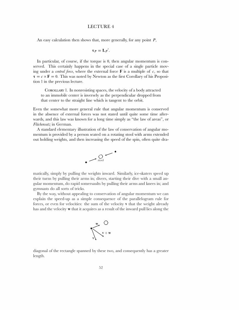
LECTURE 4
An easy calculation then shows that, more generally, for any point P�
τP D LP0:
In particular, of course, if the torque is 0� then angular momentum is con-served. This certainly happens in the special case of a single particle mov-ing under a central force, where the external force F is a multiple of c� so thatτ D c � F D 0� This was noted by Newton as the ˇrst Corollary of his Proposi-tion 1 in the previous lecture.
COROLLARY 1. In nonresisting spaces, the velocity of a body attractedto an immobile center is inversely as the perpendicular dropped fromthat center to the straight line which is tangent to the orbit.
Even the somewhat more general rule that angular momentum is conservedin the absence of external forces was not stated until quite some time after-wards, and this law was known for a long time simply as \the law of areas", orFl�achensatz in German.
A standard elementary illustration of the law of conservation of angular mo-mentum is provided by a person seated on a rotating stool with arms extendedout holding weights, and then increasing the speed of the spin, often quite dra-
matically, simply by pulling the weights inward. Similarly, ice-skaters speed uptheir turns by pulling their arms in; divers, starting their dive with a small an-gular momentum, do rapid somersaults by pulling their arms and knees in; andgymnasts do all sorts of tricks.
By the way, without appealing to conservation of angular momentum we canexplain the speed-up as a simple consequence of the parallelogram rule forforces, or even for velocities: the sum of the velocity v that the weight alreadyhas and the velocity w that it acquires as a result of the inward pull lies along the
diagonal of the rectangle spanned by these two, and consequently has a greaterlength.
52
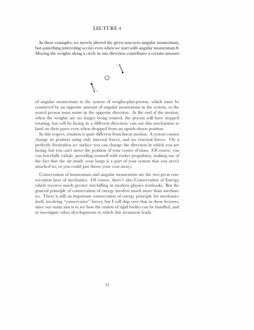
LECTURE 4
In these examples, we merely altered the given non-zero angular momentum,but something interesting occurs even when we start with angular momentum 0�
Moving the weights along a circle in one direction contributes a certain amount
of angular momentum to the system of weights-plus-person, which must becountered by an opposite amount of angular momentum in the system, so theseated person must rotate in the opposite direction. At the end of the motion,when the weights are no longer being rotated, the person will have stoppedrotating, but will be facing in a di˛erent direction; cats use this mechanism toland on their paws even when dropped from an upside-down position.
In this respect, rotation is quite di˛erent from linear motion. A system cannotchange its position using only internal forces, and no external forces. On aperfectly frictionless ice surface you can change the direction in which you arefacing, but you can't move the position of your center of mass. (Of course, youcan forcefully exhale, providing yourself with rocket propulsion, making use ofthe fact that the air inside your lungs is a part of your system that you aren'tattached to; or you could just throw your coat away.)
Conservation of momentum and angular momentum are the two great con-servation laws of mechanics. Of course, there's also Conservation of Energy,which receives much greater star-billing in modern physics textbooks. But thegeneral principle of conservation of energy involves much more than mechan-ics. There is still an important conservation of energy principle for mechanicsitself, involving \conservative" forces, but I will skip over that in these lectures,since our main aim is to see how the notion of rigid bodies can be handled, andto investigate other developments to which this treatment leads.
53
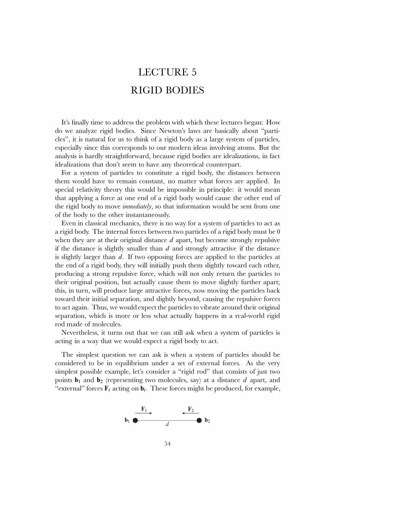
LECTURE 5
RIGID BODIES
It's ˇnally time to address the problem with which these lectures began: Howdo we analyze rigid bodies. Since Newton's laws are basically about \parti-cles", it is natural for us to think of a rigid body as a large system of particles,especially since this corresponds to our modern ideas involving atoms. But theanalysis is hardly straightforward, because rigid bodies are idealizations, in factidealizations that don't seem to have any theoretical counterpart.
For a system of particles to constitute a rigid body, the distances betweenthem would have to remain constant, no matter what forces are applied. Inspecial relativity theory this would be impossible in principle: it would meanthat applying a force at one end of a rigid body would cause the other end ofthe rigid body to move immediately, so that information would be sent from oneof the body to the other instantaneously.
Even in classical mechanics, there is no way for a system of particles to act asa rigid body. The internal forces between two particles of a rigid body must be 0when they are at their original distance d apart, but become strongly repulsiveif the distance is slightly smaller than d and strongly attractive if the distanceis slightly larger than d� If two opposing forces are applied to the particles atthe end of a rigid body, they will initially push them slightly toward each other,producing a strong repulsive force, which will not only return the particles totheir original position, but actually cause them to move slightly further apart;this, in turn, will produce large attractive forces, now moving the particles backtoward their initial separation, and slightly beyond, causing the repulsive forcesto act again. Thus, we would expect the particles to vibrate around their originalseparation, which is more or less what actually happens in a real-world rigidrod made of molecules.
Nevertheless, it turns out that we can still ask when a system of particles isacting in a way that we would expect a rigid body to act.
The simplest question we can ask is when a system of particles should beconsidered to be in equilibrium under a set of external forces. As the verysimplest possible example, let's consider a \rigid rod" that consists of just twopoints b1 and b2 (representing two molecules, say) at a distance d apart, and\external" forces Fi acting on bi� These forces might be produced, for example,
54
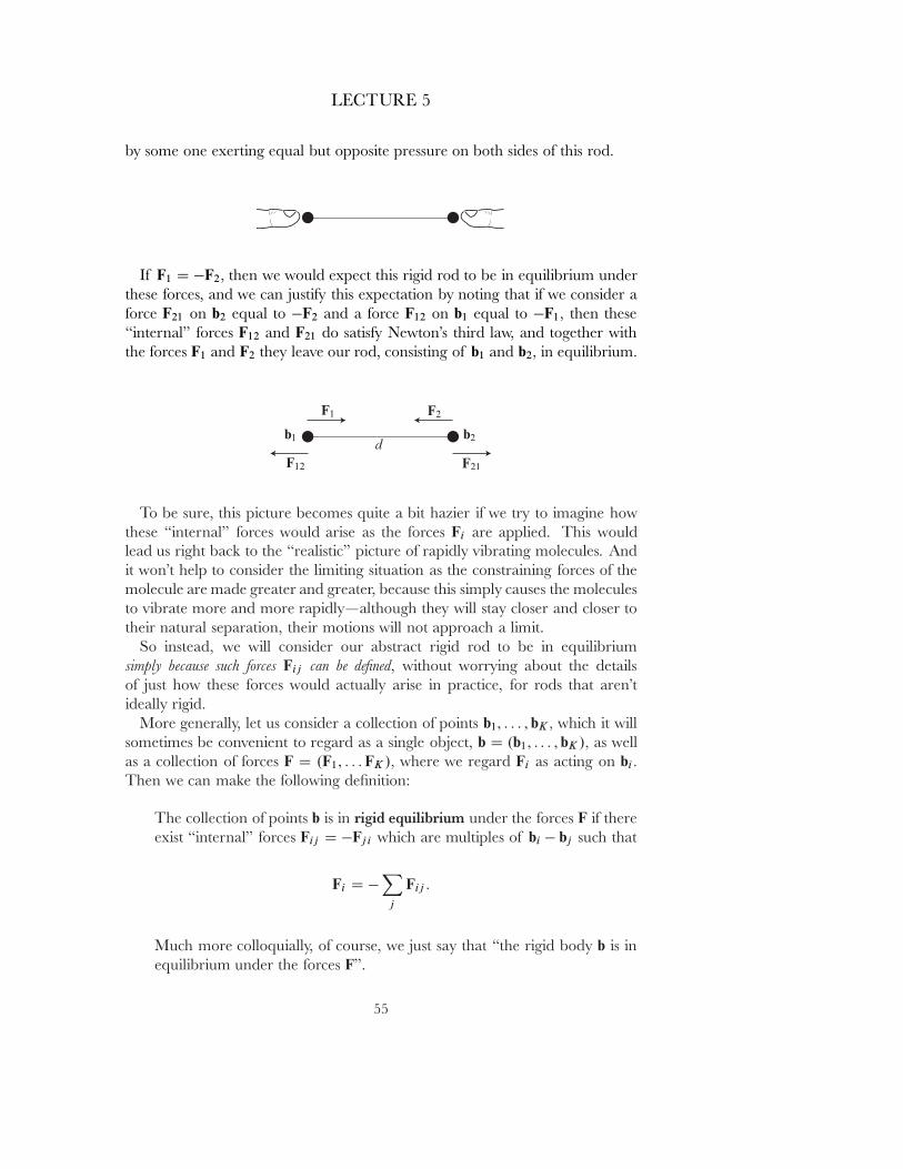
LECTURE 5
by some one exerting equal but opposite pressure on both sides of this rod.
If F1 D �F2� then we would expect this rigid rod to be in equilibrium underthese forces, and we can justify this expectation by noting that if we consider aforce F21 on b2 equal to �F2 and a force F12 on b1 equal to �F1� then these\internal" forces F12 and F21 do satisfy Newton's third law, and together withthe forces F1 and F2 they leave our rod, consisting of b1 and b2� in equilibrium.
To be sure, this picture becomes quite a bit hazier if we try to imagine howthese \internal" forces would arise as the forces Fi are applied. This wouldlead us right back to the \realistic" picture of rapidly vibrating molecules. Andit won't help to consider the limiting situation as the constraining forces of themolecule are made greater and greater, because this simply causes the moleculesto vibrate more and more rapidly|although they will stay closer and closer totheir natural separation, their motions will not approach a limit.
So instead, we will consider our abstract rigid rod to be in equilibriumsimply because such forces Fij can be deˇned, without worrying about the detailsof just how these forces would actually arise in practice, for rods that aren'tideally rigid.
More generally, let us consider a collection of points b1; : : : ; bK � which it willsometimes be convenient to regard as a single object, b D .b1; : : : ; bK /� as wellas a collection of forces F D .F1; : : : FK /� where we regard Fi as acting on bi�
Then we can make the following deˇnition:
The collection of points b is in rigid equilibrium under the forces F if thereexist \internal" forces Fij D �Fji which are multiples of bi � bj such that
Fi D �X
j
Fij :
Much more colloquially, of course, we just say that \the rigid body b is inequilibrium under the forces F".
55
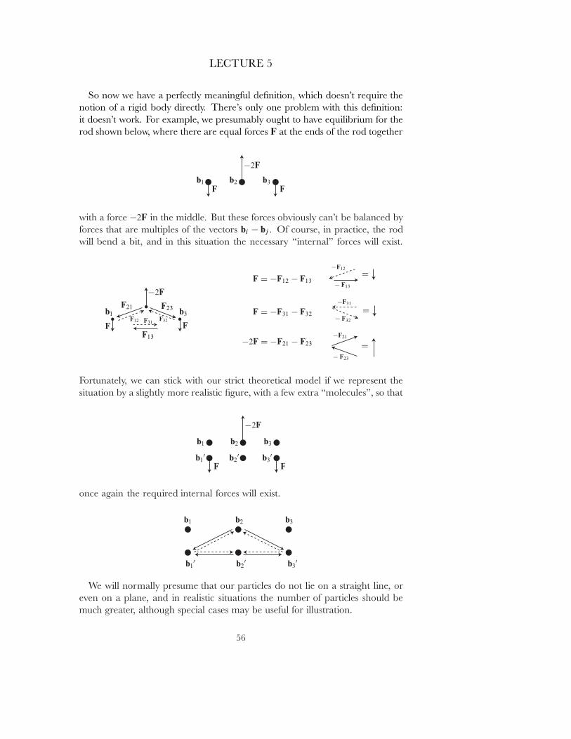
LECTURE 5
So now we have a perfectly meaningful deˇnition, which doesn't require thenotion of a rigid body directly. There's only one problem with this deˇnition:it doesn't work. For example, we presumably ought to have equilibrium for therod shown below, where there are equal forces F at the ends of the rod together
with a force �2F in the middle. But these forces obviously can't be balanced byforces that are multiples of the vectors bi � bj � Of course, in practice, the rodwill bend a bit, and in this situation the necessary \internal" forces will exist.
Fortunately, we can stick with our strict theoretical model if we represent thesituation by a slightly more realistic ˇgure, with a few extra \molecules", so that
once again the required internal forces will exist.
We will normally presume that our particles do not lie on a straight line, oreven on a plane, and in realistic situations the number of particles should bemuch greater, although special cases may be useful for illustration.
56
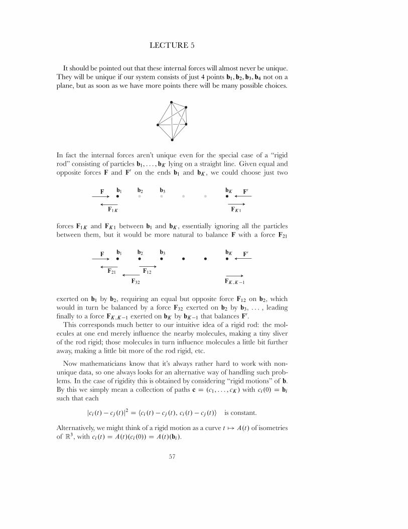
LECTURE 5
It should be pointed out that these internal forces will almost never be unique.They will be unique if our system consists of just 4 points b1; b2; b3; b4 not on aplane, but as soon as we have more points there will be many possible choices.
In fact the internal forces aren't unique even for the special case of a \rigidrod" consisting of particles b1; : : : ; bK lying on a straight line. Given equal andopposite forces F and F0 on the ends b1 and bK � we could choose just two
forces F1K and FK1 between b1 and bK � essentially ignoring all the particlesbetween them, but it would be more natural to balance F with a force F21
exerted on b1 by b2� requiring an equal but opposite force F12 on b2� whichwould in turn be balanced by a force F32 exerted on b2 by b3� : : : , leadingˇnally to a force FK ;K�1 exerted on bK by bK�1 that balances F0�
This corresponds much better to our intuitive idea of a rigid rod: the mol-ecules at one end merely in uence the nearby molecules, making a tiny sliverof the rod rigid; those molecules in turn in uence molecules a little bit furtheraway, making a little bit more of the rod rigid, etc.
Now mathematicians know that it's always rather hard to work with non-unique data, so one always looks for an alternative way of handling such prob-lems. In the case of rigidity this is obtained by considering \rigid motions" of b�
By this we simply mean a collection of paths c D .c1; : : : ; cK / with ci.0/ D bi
such that each
jci.t/ � cj .t/j2 D hci .t/ � cj .t/; ci.t/ � cj .t/i is constant.
Alternatively, we might think of a rigid motion as a curve t 7! A.t/ of isometriesof R3� with ci.t/ D A.t/.ci.0// D A.t/.bi/�
57
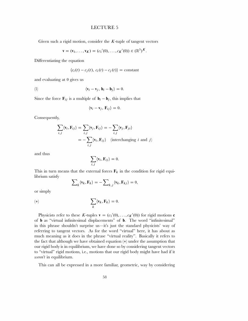
LECTURE 5
Given such a rigid motion, consider the K-tuple of tangent vectors
v D .v1; : : : ; vK / D .c10.0/; : : : ; cK
0.0// 2 .R3/K :
Di˛erentiating the equation
hci.t/ � cj .t/; ci.t/ � cj .t/i D constant
and evaluating at 0 gives us
(1) hvi � vj ; bi � bji D 0:
Since the force Fij is a multiple of bi � bj � this implies that
hvi � vj ; Fij i D 0:
Consequently,X
i;j
hvi ; Fij i DX
i;j
hvj ; Fij i D �X
i;j
hvj ; Fjii
D �X
i;j
hvi ; Fij i (interchanging i and j )
and thus X
i;j
hvi ; Fij i D 0:
This in turn means that the external forces Fk in the condition for rigid equi-librium satisfy X
khvk ; Fki D �
Xk;j
hvk ; Fkj i D 0�
or simply
(�)X
k
hvk ; Fk i D 0:
Physicists refer to these K-tuples v D .c10.0/; : : : ; cK
0.0// for rigid motions cof b as \virtual inˇnitesimal displacements" of b� The word \inˇnitesimal"in this phrase shouldn't surprise us|it's just the standard physicists' way ofreferring to tangent vectors. As for the word \virtual" here, it has about asmuch meaning as it does in the phrase \virtual reality". Basically it refers tothe fact that although we have obtained equation (�) under the assumption thatour rigid body is in equilibrium, we have done so by considering tangent vectorsto \virtual" rigid motions, i.e., motions that our rigid body might have had if itweren't in equilibrium.
This can all be expressed in a more familiar, geometric, way by considering
58
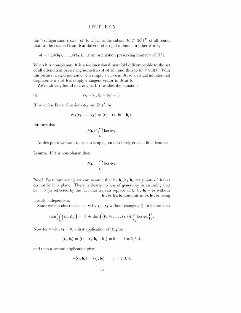
LECTURE 5
the \conˇguration space" of b� which is the subset M � .R3/K of all pointsthat can be reached from b at the end of a rigid motion. In other words,
M D f .A.b1/; : : : ; A.bK // : A an orientation preserving isometry of R3g:
When b is non-planar, M is a 6-dimensional manifold di˛eomorphic to the setof all orientation preserving isometries A of R3� and thus to R3 � SO.3/� Withthis picture, a rigid motion of b is simply a curve in M� so a virtual inˇnitesimaldisplacement v of b is simply a tangent vector to M at b�
We've already found that any such v satisˇes the equation
(1) hvi � vj ; bi � bji D 0:
If we deˇne linear functions �ij on .R3/K by
�ij .v1; : : : ; vK / D hvi � vj ; bi � bji�
this says thatMb �
\
i;j
ker �ij :
At this point we want to state a simple, but absolutely crucial, little lemma:
Lemma. If b is non-planar, then
Mb D\
i;j
ker �ij :
Proof. By renumbering, we can assume that b1; b2; b3; b4 are points of b thatdo not lie in a plane. There is clearly no loss of generality in assuming thatb1 D 0 [as re ected by the fact that we can replace all bi by bi � b1 withoutchanging (1)]. Thus our assumption on b1; b2; b3; b4 amounts to b2; b3; b4 beinglinearly independent.
Since we can also replace all vi by vi � v1 without changing (1), it follows that
dim�T
i;j
ker �ij
�D 3 C dim
�n.0; v2; : : : ; vK / 2
Ti;j
ker �ij
o�:
Now for v with v1 D 0� a ˇrst application of (1) gives
hvi ; bii D hvi � v1; bi � b1i D 0 i D 2; 3; 4�
and then a second application gives
�hvi ; bji D hvj ; bii i D 2; 3; 4:
59
LECTURE 5
So if A : R3 ! R3 is the linear transformation with
vi D Abi i D 2; 3; 4�
then A is skew-adjoint. But the dimension of skew-symmetric 3�3 matrices is 3�
so the dimension ofT
i;j ker �ij is at most 6� which is the dimension of Mb�
By the way, it shouldn't be too surprising that the mechanics of this proof in-volved skew-adjoint transformations, since they are the derivatives of orthogonalones (as we noted in our discussion of the cross-product); given the transforma-tion A of the proof, the isometries etA would produce the given inˇnitesimalvirtual displacement v�
If we use h ; i for the usual inner product on .R3/K � then equation (�) canbe written in the simple form
hv; Fi D 0;
in other words, F is perpendicular to the tangent space Mb� The inner productof force and distance is generally called work, so this sum is also called the \(vir-tual) inˇnitesimal work" done by the forces F during the (virtual) inˇnitesimaldisplacement v� Our little calculation that hv; Fi D 0 if b is in rigid equilibriumunder F is often referred to by physicists as a proof of the \principle of virtualwork". In reality, however, when physicists use the principle of virtual work theyalmost always assume implicitly that it includes the converse :
The Principle of Virtual Work. The virtual inˇnitesimal work hv; Fi equals 0 forall virtual inˇnitesimal displacements v of (a non-planar) b if and only if b is inrigid equilibrium under F�
Proof. We only have to prove the converse part, that if hv; Fi D 0 for all v�
then b is in rigid equilibrium under F� If we consider the linear function ˆ on.R3/K deˇned by
ˆ.v1; : : : ; vK / DX
k
hvk ; Fk i�
then our hypothesis says that ˆ vanishes on Mb� and thus by our lemma,
ˆ vanishes on\
i;j
ker �ij � �ij .v1; : : : ; vK / D hvi � vj ; bi � bji:
It is a well-known simple result about vector spaces (not necessarily even ˇnitedimensional ones) that in this case there exist constants �ij with
ˆ DX
i;j
�ij � �ij :
60
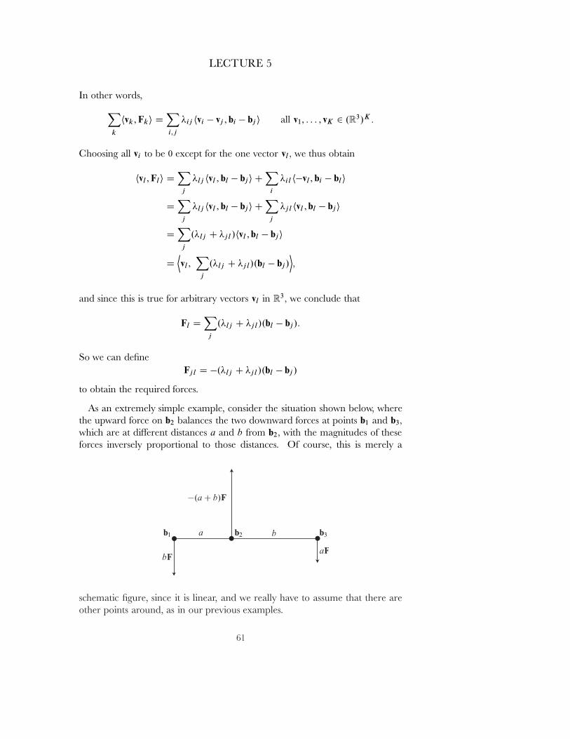
LECTURE 5
In other words,X
k
hvk ; Fki DX
i;j
�ij hvi � vj ; bi � bj i all v1; : : : ; vK 2 .R3/K �
Choosing all vi to be 0 except for the one vector vl � we thus obtain
hvl ; Fl i DX
j
�lj hvl ; bl � bji CX
i
�il h�vl ; bi � bl i
DX
j
�lj hvl ; bl � bji CX
j
�jl hvl ; bl � bji
DX
j
.�lj C �jl /hvl ; bl � bji
DDvl ;
X
j
.�lj C �jl /.bl � bj/E�
and since this is true for arbitrary vectors vl in R3� we conclude that
Fl DX
j
.�lj C �jl /.bl � bj/:
So we can deˇneFjl D �.�lj C �jl /.bl � bj /
to obtain the required forces.
As an extremely simple example, consider the situation shown below, wherethe upward force on b2 balances the two downward forces at points b1 and b3�
which are at di˛erent distances a and b from b2� with the magnitudes of theseforces inversely proportional to those distances. Of course, this is merely a
schematic ˇgure, since it is linear, and we really have to assume that there areother points around, as in our previous examples.
61
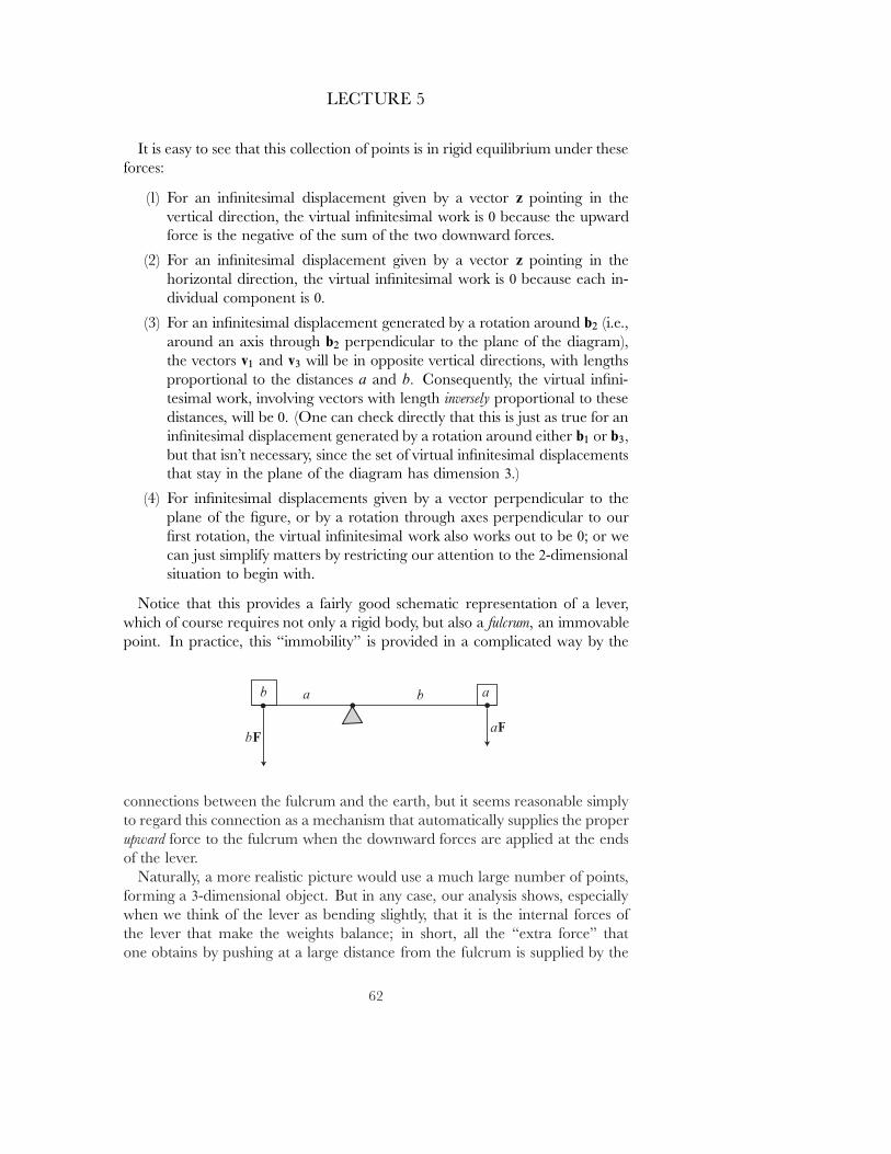
LECTURE 5
It is easy to see that this collection of points is in rigid equilibrium under theseforces:
(1) For an inˇnitesimal displacement given by a vector z pointing in thevertical direction, the virtual inˇnitesimal work is 0 because the upwardforce is the negative of the sum of the two downward forces.
(2) For an inˇnitesimal displacement given by a vector z pointing in thehorizontal direction, the virtual inˇnitesimal work is 0 because each in-dividual component is 0�
(3) For an inˇnitesimal displacement generated by a rotation around b2 (i.e.,around an axis through b2 perpendicular to the plane of the diagram),the vectors v1 and v3 will be in opposite vertical directions, with lengthsproportional to the distances a and b� Consequently, the virtual inˇni-tesimal work, involving vectors with length inversely proportional to thesedistances, will be 0� (One can check directly that this is just as true for aninˇnitesimal displacement generated by a rotation around either b1 or b3�
but that isn't necessary, since the set of virtual inˇnitesimal displacementsthat stay in the plane of the diagram has dimension 3�)
(4) For inˇnitesimal displacements given by a vector perpendicular to theplane of the ˇgure, or by a rotation through axes perpendicular to ourˇrst rotation, the virtual inˇnitesimal work also works out to be 0; or wecan just simplify matters by restricting our attention to the 2-dimensionalsituation to begin with.
Notice that this provides a fairly good schematic representation of a lever,which of course requires not only a rigid body, but also a fulcrum, an immovablepoint. In practice, this \immobility" is provided in a complicated way by the
connections between the fulcrum and the earth, but it seems reasonable simplyto regard this connection as a mechanism that automatically supplies the properupward force to the fulcrum when the downward forces are applied at the endsof the lever.
Naturally, a more realistic picture would use a much large number of points,forming a 3-dimensional object. But in any case, our analysis shows, especiallywhen we think of the lever as bending slightly, that it is the internal forces ofthe lever that make the weights balance; in short, all the \extra force" thatone obtains by pushing at a large distance from the fulcrum is supplied by the
62
LECTURE 5
lever itself, in its e˛ort to preserve rigidity (together with the force that the earthsupplies on the fulcrum, to keep it from moving downward).
Now we are ready to apply the same ideas in the more general case. Insteadof looking for a condition for equilibrium, we now seek a criterion for a rigidmotion c D .c1; : : : ; cK / of b D .b1; : : : ; bK / to be consistent with the forcesF D .F1; : : : FK /� We will think of the Fi as functions on M � R� so the forcesmay depend not only on time, but also on the particular rigid motion that thebody has undergone at any particular time.
We now need \internal" forces Fij .t/ D �Fji.t/ with Fij .t/ a multiple ofci.t/ � cj .t/ so that
mici00.t/ D Fi.c.t/; t/ C
Pj Fij .t/
ormici
00.t/ � Fi.c.t/; t/ DP
j Fij .t/:
The latter equation, which may be regarded as stating that the body is in rigidequilibrium under the forces Fi �mici
00� is often called \d'Alembert's principle"and regarded as the fundamental law|so that, as the physicists like to say,\dynamics reduces to statics" (in the words of [Go], Chapter 1.4). But thisreally becomes useful only when we apply the principle of virtual work: Theconditions on the Fij imply that
Pihvi; mici
00.t/ � Fi.c.t/; t/i D 0
for all tangent vectors v� and, conversely, the principle of virtual work impliesthat if this condition holds, then the requisite Fij .t/ exist. This leads us to thefollowing deˇnition:
d'Alembert's Principle: The rigid motion c is a rigid solution for theforces F� or, more colloquially, \c is a possible motion of the rigidbody b under the forces F", if for each t�
X
i
hFi.c.t/; t/ � mici00.t/; vii D 0
for all tangent vectors v at Mc.t/�
If we agree to let mc denote .m1c1; : : : ; mK cK / and similarly for mc00� andalso let h ; i denote the usual inner product on .R3/K � then we can write
hF.c.t/; t/ � mc00.t/; vi D 0 for all v tangent to Mc.t/�
or, if we are willing to tolerate a little ambiguity in our notation, simply
(��) hF � mc00; vi D 0 for all v tangent to Mc:
63
LECTURE 5
Our condition amounts to a system of second order di˛erential equations forvector-valued functions: If we choose a local coordinate system x1; : : : ; x6 onthe 6-dimensional manifold M� then we only have to verify (��) for v D @=@xi �
giving us 6 equations for the vector-valued functions ci D xi B c�
Since M is basically R3 � SO.3/� we can restate this much more concretely.One 3-dimensional collection of vector ˇelds tangent to M are those of the formvi D z for a constant vector z� Condition (��) becomes
0 DX
i
hFi � mici00; zi
DDP
iFi ; zE�DP
imici00; zE�
Since this must hold for all z� we must have
(Frigid) Ftotal DX
i
Fi DX
i
mici00 D MC 00�
where C is the center of mass, and M DP
i mi is the total mass [recall that Fi
really stands for t 7! Fi.c.t/; t/].We also have to consider the vector ˇelds generated by rotations. As we saw
in our discussion of the �-product, these are of the form vi D ci � η� Thus,condition (��) becomes
0 DX
i
hFi � mici00; ci � ηi
DX
i
hFi ; ci � ηi �X
i
mihci00; ci � ηi
DX
i
hci � Fi ;ηi �X
i
mihci � ci00;ηi:
Since this must hold for all η� we must have [with Fi standing for t 7! Fi.c.t/; t/]
(τrigid) τ DX
i
ci � Fi DX
i
mici � ci00:
Condition (Frigid) simply says that the rigid body must move in such a waythat the momentum law is satisˇed, while condition (τrigid) simply says that therigid body must move in such a way that the angular momentum law is satisˇed.
To solve these equations we might begin by writing our rigid motion c D.c1; : : : ; cK / of b in the form
ci.t/ D B�1.t/.bi/ C w.t/
D Bt.t/.bi/ C w.t/
64
LECTURE 5
for orthogonal B.t/; we've used B�1 instead of B to conform to the physicists'convention that B.t/ is the rotation that will return the body at time t to itsoriginal unrotated position. Since BtB D I� we have
Bt0B D �BtB 0
D �.B 0tB/t
D �.Bt0B/t�
so .Bt0B/.t/ is skew-adjoint, and its matrix can be written as0@
0 �!3.t/ !2.t/
!3.t/ 0 �!1.t/
�!2.t/ !1.t/ 0
1A :
Setting ω.t/ D�!1.t/; !2.t/; !3.t/
�� we then have
vi.t/ D ci0.t/ D Bt0.t/.bi/ C w0.t/
D�Bt0.t/B.t/
��B�1.t/.bi/
�C w0.t/
D .Bt0.t/B.t//.ci .t// C w0.t/
D ci.t/ �
0@
0 �!3.t/ !2.t/
!3.t/ 0 �!1.t/
�!2.t/ !1.t/ 0
1AC w0.t/
D Œω.t/ � ci.t/� C w0.t/:
There is a natural choice for B.t/ and w.t/ in our description of rigid bodymotion: choose w.t/ D C.t/� where C.t/ is the center of mass at time t� so thatB.t/ represents the rotation about the center of mass required to move the bodyback to its initial unrotated position. We then have
vi.t/ D Œω.t/ � ci.t/� C C 0:
We can now write the angular momentum A of c asX
i
mici � vi DX
i
mici
�.ω � ci/ C C 0�
DX
i
�mici � .ω � ci/
�C�X
i
mici
�� C 0
DX
i
�mici � .ω � ci/
�C�MC � C 0�� M D
Pi mi �
Comparing this with the formula on page 51, we see that the quantityX
i
mici � .ω � ci/
65
LECTURE 5
is the same as the \rotational angular momentum", that is, the angular momen-tum of c around its center of mass.
For the moment we only want to consider the basic aspects of solving equa-tions (Frigid) and (τrigid). To simplify matters, we'll ignore the motion of thecenter of mass, and just look for a solution of the form ci D Bt.bi/� essentiallydescribing how the body rotates about the center of mass.
Thus, we are looking for ω so that (τrigid) holds when we have
ci0 D vi D ω � ci :
We have
ci00 D .ω0 � ci/ C .ω � ci
0/
D .ω0 � ci/ C .ω � .ω � ci//�
so equation (τrigid) becomes
τ DX
i
mici � .ω0 � ci/ CX
i
mi.ω � .ω � ci//:
In terms of the linear function Ic : R3 ! R3 deˇned by
Ic.η/ DX
i
mici � .η � ci/�
we can write this as
(�) Ic.ω0/ D τ �X
i
mi.ω � .ω � ci//�
where the right side depends on c 2 M and ω� The only thing we need to checkis that we can always solve this for some ω0 as a function of c and ω� therebyobtaining a system of ˇrst order equations for ω0� and thus a system of secondorder equations for the elements of B� In other words, we need to know thatthe linear transformation Ic is an isomorphism for all c 2 M�
Since we only have to consider c 2 M of the form ci D P.bi/ for someorthogonal P� we have
Ic.η/ DX
i
miP.bi/ � .η � P.bi//
D P�P
i mibi � .P�1.η/ � bi/�
D .PIbP�1/.η/:
Thus we only have to check that I D Ib is an isomorphism, where
I.φ/ DX
i
mibi � .φ � bi/ for φ 2 R3�
66
LECTURE 5
Now for any ψ 2 R3 we have
hI.φ/;ψi DX
i
hmi bi � .φ� bi/; ψi
DX
i
mihφ� bi; ψ � bii
DX
i
mihψ � bi; φ � bii
D hI.ψ/;φi:
Thus I is self-adjoint, and consequently has an orthonormal basis of eigenvec-tors. Since
hI.φ/;φi DX
i
mi jφ � bij2�
the corresponding eigenvalues are all � 0� and in fact they are all > 0 becausewe are assuming that b is non-planar, and thus at least one jφ� bi j > 0� Since Ialways has positive eigenvalues, it is always an isomorphism, so we can indeedalways solve equation (�) for ω0�
The map I D Ib is called the inertia tensor of b� I should say that this is nothow the inertia tensor is usually introduced (in fact, I don't know of any physicstext that does introduce it this way), but it's the way it should be introduced!
The directions of the eigenvalues of the inertia tensor are called the princi-
pal axes of inertia, and the corresponding eigenvalues are called the principal
moments of inertia. As our rigid body moves under the rotations B�1.t/� theinertia tensor for B�1.t/.b/ is just the composition B�1.t/BIBB.t/; the principalmoments of inertia remain the same for all positions of the rigid body underthe motion, while the principal axes of inertia are transformed by the B�1.t/�
Aside from the values of Ftotal and τ� the principal moments of inertia arethe only other data entering into our equations, so, in a sense, the whole motionof the rigid body b depends only on them. In particular, for motion under noexternal forces, we obtain exactly the same equations for two rigid bodies ofarbitrary shape, provided only that they have the same principal moments ofinertia.
We've described the inertia tensor rather abstractly, but it is not hard to writedown the matrix of I with respect to the standard basis .e1; e2; e3/� temporarilyadopting the notation bi D .xi; yi; zi/�
I should remind you of the identity
w � .u � v/ D hw; viu � hw; uiv
which we can prove by noting that w � .u � v/ is perpendicular to u � v� so itis a linear combination of u and v� and the appropriate coeıcients are easy todetermine using the usual identities for ��
67
LECTURE 5
With this identity at hand, we can write
I.ω/ DX
i
mi.jbij2ω � hbi;ωibi/�
which gives
I.e1/ DX
i
mi
�jbi j2e1 � hbi; e1ibi
�
DX
i
mi
�jbi j2e1 � xi.xi; yi; zi/
�
DX
i
mi
�yi
2 C zi2; �xiyi ; �xizi
��
with similar results for e2 and e3� Thus, the matrix of I with respect to thestandard basis .e1; e2; e3/ is
I D
0BBB@
Pi mi.yi
2 C zi2/ �
Pi mixiyi �
Pi mixizi
�P
i miyixi
Pi mi.xi
2 C zi2/ �
Pi miyizi
�P
i mizixi �P
i miziyi
Pi mi.xi
2 C yi2/
1CCCA :
The same result obviously holds for any orthonormal basis .v1; v2; v3/ if we setxi D hbi; v1i� yi D hbi; v2i� and zi D hbi ; v3i�
The diagonal terms of the matrix of I with respect to an orthonormal basisare the quantities that were classically called the \moments of inertia" of babout the axes; the o˛-diagonal terms are sometimes called the \products ofinertia". In other words, the moment of inertia IA of b about an axis A is
IA DX
i
miri2�
where ri is the distance from bi to A� If our orthonormal coordinate systemhappens to point along the principal axes, then these moments of inertia arethe principal moments of inertia.
As we might expect, for a rigid body b a special role is played by the mo-ment of inertia about the axes that pass through the center of gravity C D.xC ; yC ; zC /� More generally, there is a simple relationship between the ma-trix I and the matrix I0 of the inertia tensor of b in a parallel coordinatesystem whose origin is C� Let
xi D Nxi C xC ; yi D Nyi C yC ; zi D Nzi C zC �
so that . Nxi; Nyi ; Nzi/ are the coordinates of the rigid body in this system, and letM D
Pi mi � When we write I in terms of the Nxi; Nyi ; Nzi� any cross term like
68
LECTURE 5
Pi mi NyiyC vanishes, since
Pi mi Nyi D
Pi mi.yi � yC / D
Pi miyi � MyC �
which is 0 by deˇnition of yC � Thus, we obtain simply
I D I0 C M �
0@
yC2 C zC
2 �xC yC �xC zC
�yC xC xC2 C zC
2 �yC zC
�zC xC �zC yC xC2 C yC
2
1A
D I0 C IC �
where IC is the matrix of the inertia tensor of the single body C with mass M
around the origin of our original coordinate system.In particular, we have
The Parallel Axis Theorem (Steiner's Theorem). If the point P is at distanced from the center of mass C of b� the moment of inertia of b about any axisthrough P is Md2 plus the moment of inertia about the parallel axis through C�
The parallel axis theorem is actually most useful when we make the obviousgeneralizations to a continuous rigid body B with density �� First of all, thetotal mass M is given by
M DZ
B
� DZ
B
�.x;y; z/ dx dy dz�
using x;y; z for the standard coordinate functions on R3� The center of massis the vector given by
C D1
M
Z
B
�.x; y; z/.x; y; z/ dx dy dz�
i.e., C is the point of R3 with coordinatesRB
x ��.x;y; z/ dx dy dz;RB
y ��.x; y; z/ dx dy dz;RB
z ��.x; y; z/ dx dy dz:
The inertia tensor of B is the linear transformation whose matrix I with respectto the standard basis .e1; e2; e3/ is given by0BBBBBBB@
RB
� � .y2 C z2/ dx dy dz �RB
� �xy dx dy dz �RB
� �xz dx dy dz
�RB
� �yx dx dy dzRB
� � .x2 C z2/ dx dy dz �RB
� �yz dx dy dz
�RB
� �zx dx dy dz �RB
� �zy dx dy dzRB
� � .x2 C y2/ dx dy dz
1CCCCCCCA
:
69
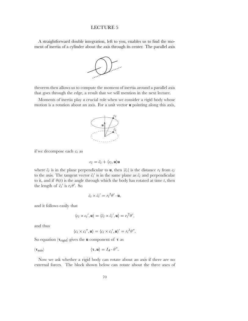
LECTURE 5
A straightforward double integration, left to you, enables us to ˇnd the mo-ment of inertia of a cylinder about the axis through its center. The parallel axis
theorem then allows us to compute the moment of inertia around a parallel axisthat goes through the edge, a result that we will mention in the next lecture.
Moments of inertia play a crucial role when we consider a rigid body whosemotion is a rotation about an axis. For a unit vector u pointing along this axis,
if we decompose each ci as
ci D Nci C hci ; uiu
where Nci is in the plane perpendicular to u� then j Nci j is the distance ri from ci
to the axis. The tangent vector Nci0 is in the same plane as Nci and perpendicular
to it, and if �.t/ is the angle through which the body has rotated at time t� thenthe length of Nci
0 is ri�0� So
Nci � Nci0 D ri
2� 0 � u�
and it follows easily that
hci � ci0; ui D hNci � Nci
0; ui D ri2� 0�
and thushci � ci
00; ui D hci � ci0; ui0 D ri
2� 00:
So equation (τrigid) gives the u component of τ as
(τaxis) hτ; ui D IA � � 00:
Now we ask whether a rigid body can rotate about an axis if there are noexternal forces. The block shown below can rotate about the three axes of
70
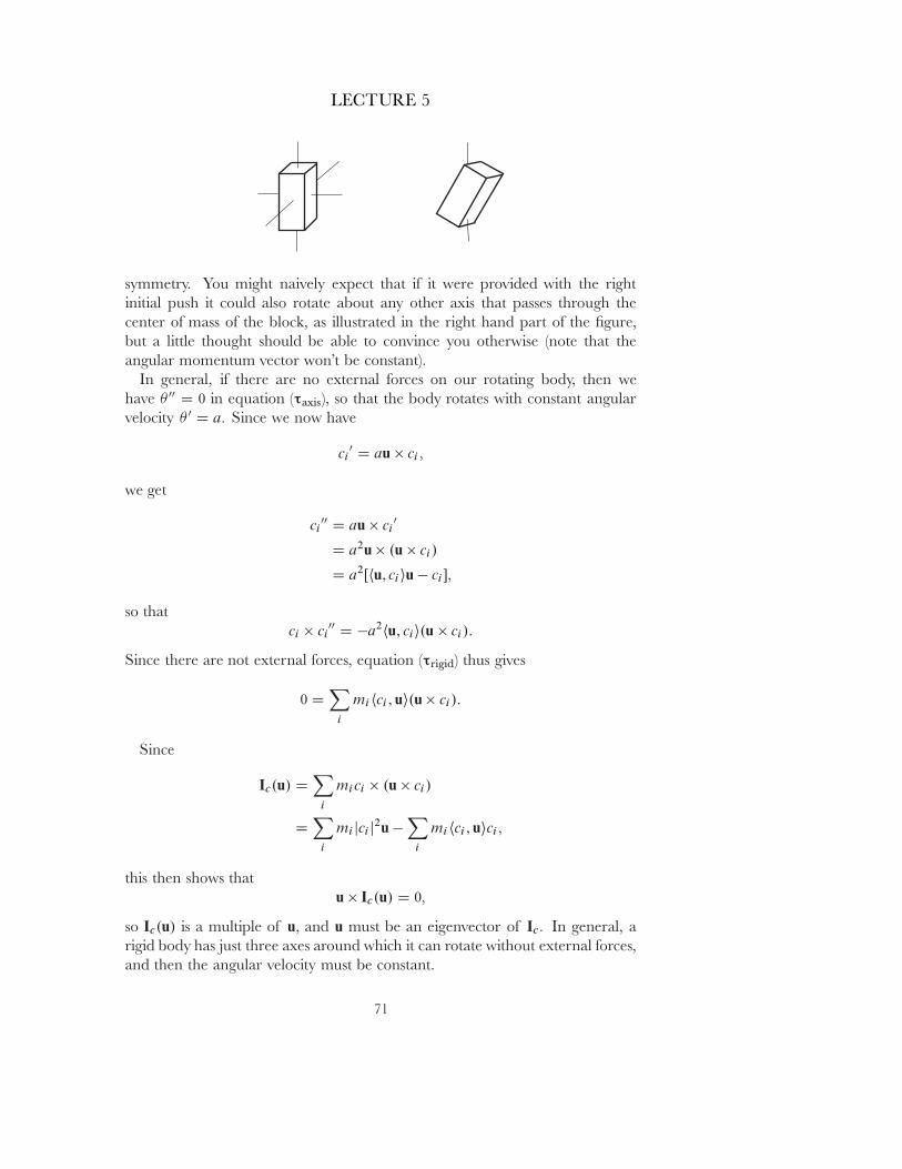
LECTURE 5
symmetry. You might naively expect that if it were provided with the rightinitial push it could also rotate about any other axis that passes through thecenter of mass of the block, as illustrated in the right hand part of the ˇgure,but a little thought should be able to convince you otherwise (note that theangular momentum vector won't be constant).
In general, if there are no external forces on our rotating body, then wehave � 00 D 0 in equation (τaxis), so that the body rotates with constant angularvelocity � 0 D a� Since we now have
ci0 D au � ci �
we get
ci00 D au � ci
0
D a2u � .u � ci/
D a2Œhu; ciiu � ci ��
so thatci � ci
00 D �a2hu; cii.u � ci/:
Since there are not external forces, equation (τrigid) thus gives
0 DX
i
mihci ; ui.u � ci/:
Since
Ic.u/ DX
i
mici � .u � ci/
DX
i
mi jci j2u �X
i
mihci ; uici �
this then shows thatu � Ic.u/ D 0�
so Ic.u/ is a multiple of u� and u must be an eigenvector of Ic� In general, arigid body has just three axes around which it can rotate without external forces,and then the angular velocity must be constant.
71
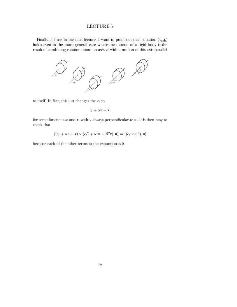
LECTURE 5
Finally, for use in the next lecture, I want to point out that equation (τaxis)holds even in the more general case where the motion of a rigid body is theresult of combining rotation about an axis A with a motion of this axis parallel
to itself. In fact, this just changes the ci to
ci C ˛u C v�
for some functions ˛ and v� with v always perpendicular to u� It is then easy tocheck that
h.ci C ˛u C v/ � .ci00 C ˛00u C ˇ00v/; ui D h.ci � ci
00/; ui�
because each of the other terms in the expansion is 0�
72
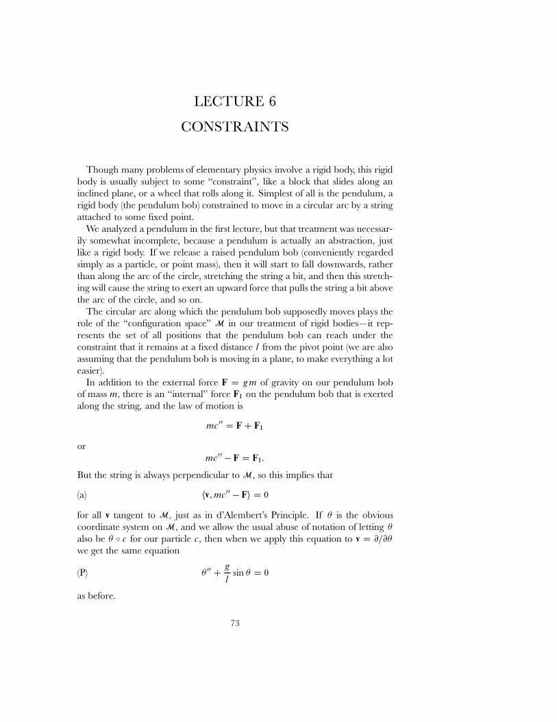
LECTURE 6
CONSTRAINTS
Though many problems of elementary physics involve a rigid body, this rigidbody is usually subject to some \constraint", like a block that slides along aninclined plane, or a wheel that rolls along it. Simplest of all is the pendulum, arigid body (the pendulum bob) constrained to move in a circular arc by a stringattached to some ˇxed point.
We analyzed a pendulum in the ˇrst lecture, but that treatment was necessar-ily somewhat incomplete, because a pendulum is actually an abstraction, justlike a rigid body. If we release a raised pendulum bob (conveniently regardedsimply as a particle, or point mass), then it will start to fall downwards, ratherthan along the arc of the circle, stretching the string a bit, and then this stretch-ing will cause the string to exert an upward force that pulls the string a bit abovethe arc of the circle, and so on.
The circular arc along which the pendulum bob supposedly moves plays therole of the \conˇguration space" M in our treatment of rigid bodies|it rep-resents the set of all positions that the pendulum bob can reach under theconstraint that it remains at a ˇxed distance l from the pivot point (we are alsoassuming that the pendulum bob is moving in a plane, to make everything a loteasier).
In addition to the external force F D gm of gravity on our pendulum bobof mass m� there is an \internal" force F1 on the pendulum bob that is exertedalong the string, and the law of motion is
mc00 D F C F1
ormc00 � F D F1:
But the string is always perpendicular to M� so this implies that
(a) hv; mc00 � Fi D 0
for all v tangent to M� just as in d'Alembert's Principle. If � is the obviouscoordinate system on M� and we allow the usual abuse of notation of letting �
also be � B c for our particle c� then when we apply this equation to v D @=@�
we get the same equation
(P) � 00 Cg
lsin � D 0
as before.
73
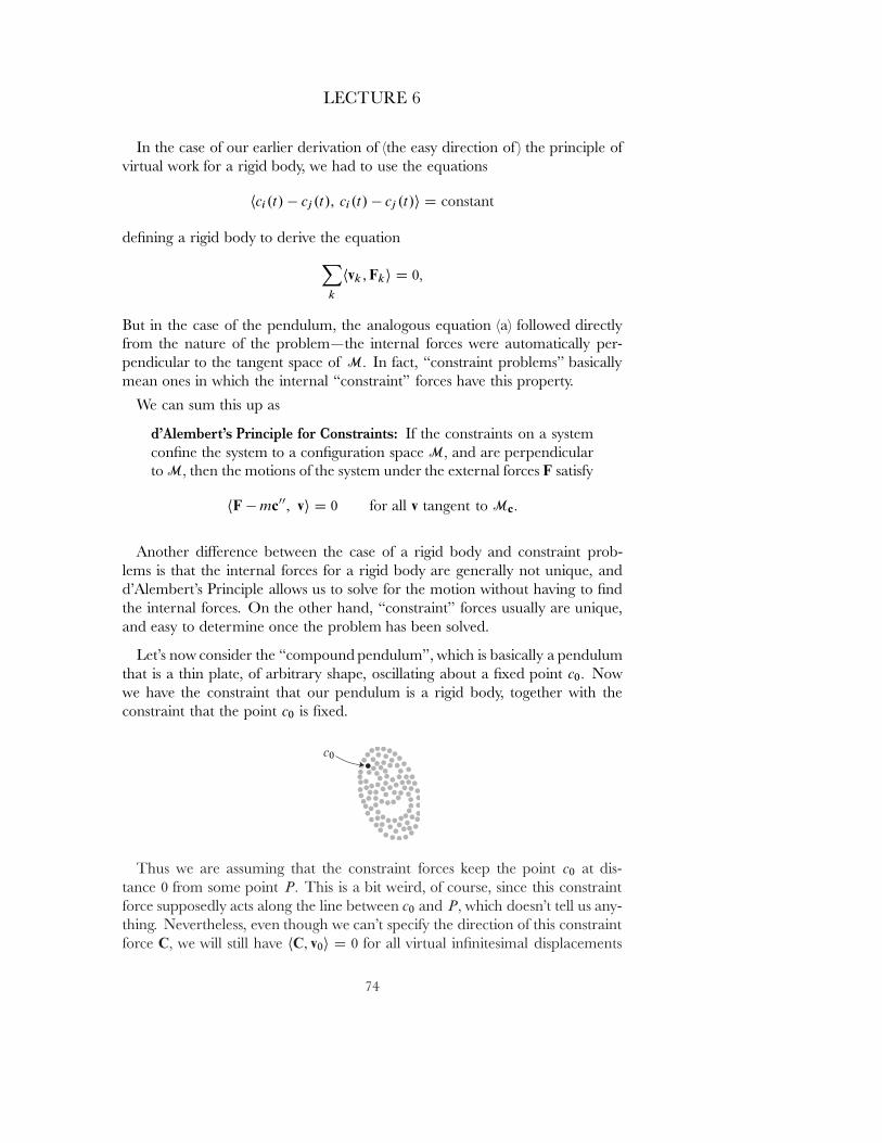
LECTURE 6
In the case of our earlier derivation of (the easy direction of ) the principle ofvirtual work for a rigid body, we had to use the equations
hci.t/ � cj .t/; ci.t/ � cj .t/i D constant
deˇning a rigid body to derive the equationX
k
hvk ; Fki D 0�
But in the case of the pendulum, the analogous equation (a) followed directlyfrom the nature of the problem|the internal forces were automatically per-pendicular to the tangent space of M� In fact, \constraint problems" basicallymean ones in which the internal \constraint" forces have this property.
We can sum this up as
d'Alembert's Principle for Constraints: If the constraints on a systemconˇne the system to a conˇguration space M� and are perpendicularto M� then the motions of the system under the external forces F satisfy
hF � mc00; vi D 0 for all v tangent to Mc�
Another di˛erence between the case of a rigid body and constraint prob-lems is that the internal forces for a rigid body are generally not unique, andd'Alembert's Principle allows us to solve for the motion without having to ˇndthe internal forces. On the other hand, \constraint" forces usually are unique,and easy to determine once the problem has been solved.
Let's now consider the \compound pendulum", which is basically a pendulumthat is a thin plate, of arbitrary shape, oscillating about a ˇxed point c0� Nowwe have the constraint that our pendulum is a rigid body, together with theconstraint that the point c0 is ˇxed.
Thus we are assuming that the constraint forces keep the point c0 at dis-tance 0 from some point P� This is a bit weird, of course, since this constraintforce supposedly acts along the line between c0 and P� which doesn't tell us any-thing. Nevertheless, even though we can't specify the direction of this constraintforce C� we will still have hC; v0i D 0 for all virtual inˇnitesimal displacements
74
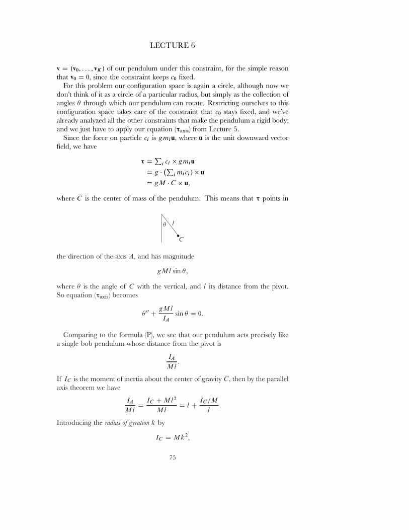
LECTURE 6
v D .v0; : : : ; vK / of our pendulum under this constraint, for the simple reasonthat v0 D 0� since the constraint keeps c0 ˇxed.
For this problem our conˇguration space is again a circle, although now wedon't think of it as a circle of a particular radius, but simply as the collection ofangles � through which our pendulum can rotate. Restricting ourselves to thisconˇguration space takes care of the constraint that c0 stays ˇxed, and we'vealready analyzed all the other constraints that make the pendulum a rigid body;and we just have to apply our equation (τaxis) from Lecture 5.
Since the force on particle ci is gmiu� where u is the unit downward vectorˇeld, we have
τ DP
i ci � gmiu
D g ��P
i mici/ � u
D gM � C � u�
where C is the center of mass of the pendulum. This means that τ points in
the direction of the axis A� and has magnitude
gMl sin ��
where � is the angle of C with the vertical, and l its distance from the pivot.So equation (τaxis) becomes
� 00 CgMl
IAsin � D 0:
Comparing to the formula (P), we see that our pendulum acts precisely likea single bob pendulum whose distance from the pivot is
IA
Ml:
If IC is the moment of inertia about the center of gravity C� then by the parallelaxis theorem we have
IA
MlD
IC C Ml2
MlD l C
IC=M
l:
Introducing the radius of �ration k by
IC D Mk2�
75
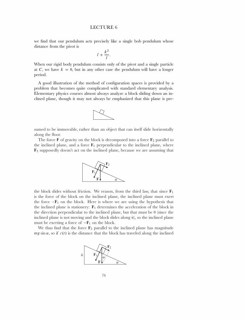
LECTURE 6
we ˇnd that our pendulum acts precisely like a single bob pendulum whosedistance from the pivot is
l Ck2
l:
When our rigid body pendulum consists only of the pivot and a single particleat C� we have k D 0� but in any other case the pendulum will have a longerperiod.
A good illustration of the method of conˇguration spaces is provided by aproblem that becomes quite complicated with standard elementary analysis.Elementary physics courses almost always analyze a block sliding down an in-clined plane, though it may not always be emphasized that this plane is pre-
sumed to be immovable, rather than an object that can itself slide horizontallyalong the oor.
The force F of gravity on the block is decomposed into a force F2 parallel tothe inclined plane, and a force F1 perpendicular to the inclined plane, whereF2 supposedly doesn't act on the inclined plane, because we are assuming that
the block slides without friction. We reason, from the third law, that since F1
is the force of the block on the inclined plane, the inclined plane must exertthe force �F1 on the block. Here is where we are using the hypothesis thatthe inclined plane is stationery: F1 determines the acceleration of the block inthe direction perpendicular to the inclined plane, but that must be 0 (since theinclined plane is not moving and the block slides along it), so the inclined planemust be exerting a force of �F1 on the block.
We thus ˇnd that the force F2 parallel to the inclined plane has magnitudemg sin ˛� so if c.t/ is the distance that the block has traveled along the inclined
76
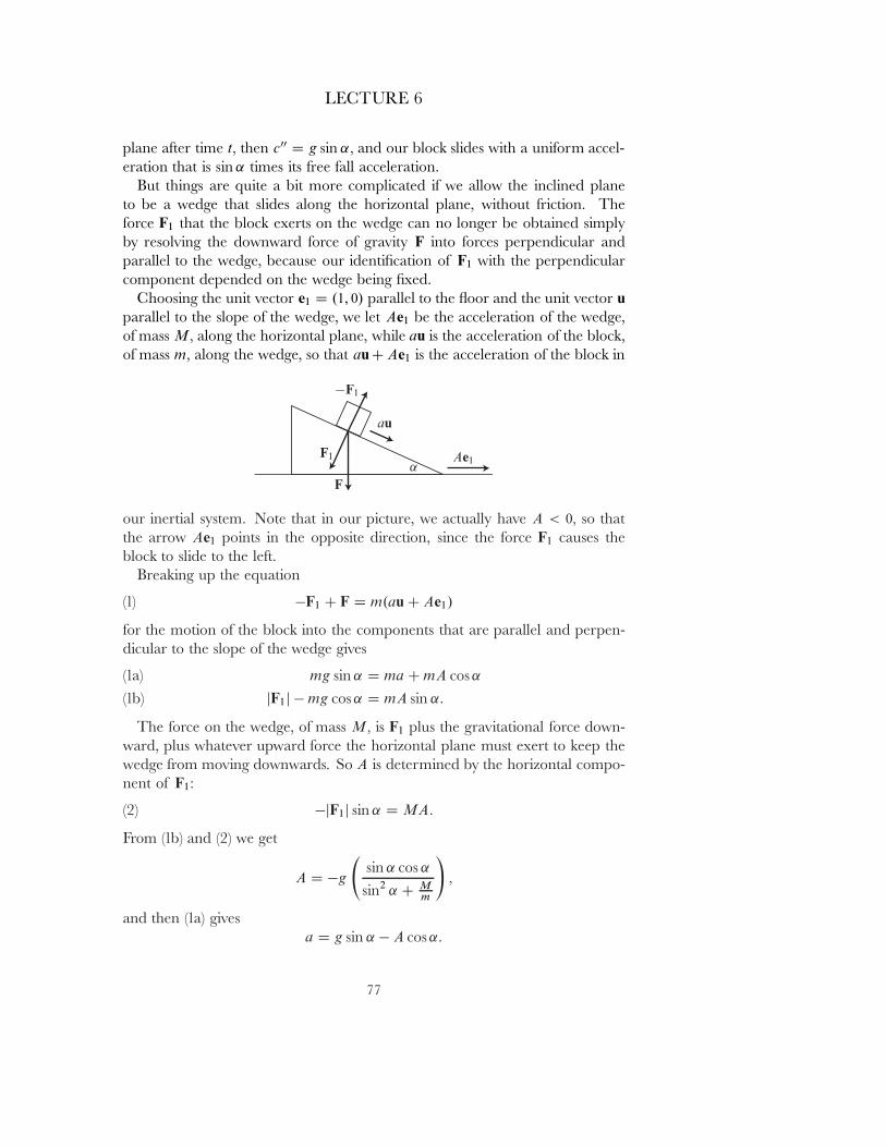
LECTURE 6
plane after time t� then c00 D g sin ˛� and our block slides with a uniform accel-eration that is sin ˛ times its free fall acceleration.
But things are quite a bit more complicated if we allow the inclined planeto be a wedge that slides along the horizontal plane, without friction. Theforce F1 that the block exerts on the wedge can no longer be obtained simplyby resolving the downward force of gravity F into forces perpendicular andparallel to the wedge, because our identiˇcation of F1 with the perpendicularcomponent depended on the wedge being ˇxed.
Choosing the unit vector e1 D .1; 0/ parallel to the oor and the unit vector uparallel to the slope of the wedge, we let Ae1 be the acceleration of the wedge,of mass M� along the horizontal plane, while au is the acceleration of the block,of mass m� along the wedge, so that au C Ae1 is the acceleration of the block in
our inertial system. Note that in our picture, we actually have A < 0� so thatthe arrow Ae1 points in the opposite direction, since the force F1 causes theblock to slide to the left.
Breaking up the equation
(1) �F1 C F D m.au C Ae1/
for the motion of the block into the components that are parallel and perpen-dicular to the slope of the wedge gives
mg sin ˛ D ma C mA cos ˛(1a)jF1j � mg cos ˛ D mA sin ˛:(1b)
The force on the wedge, of mass M� is F1 plus the gravitational force down-ward, plus whatever upward force the horizontal plane must exert to keep thewedge from moving downwards. So A is determined by the horizontal compo-nent of F1:
(2) �jF1j sin ˛ D MA:
From (1b) and (2) we get
A D �g
sin ˛ cos ˛
sin2 ˛ C Mm
!�
and then (1a) givesa D g sin ˛ � A cos ˛:
77
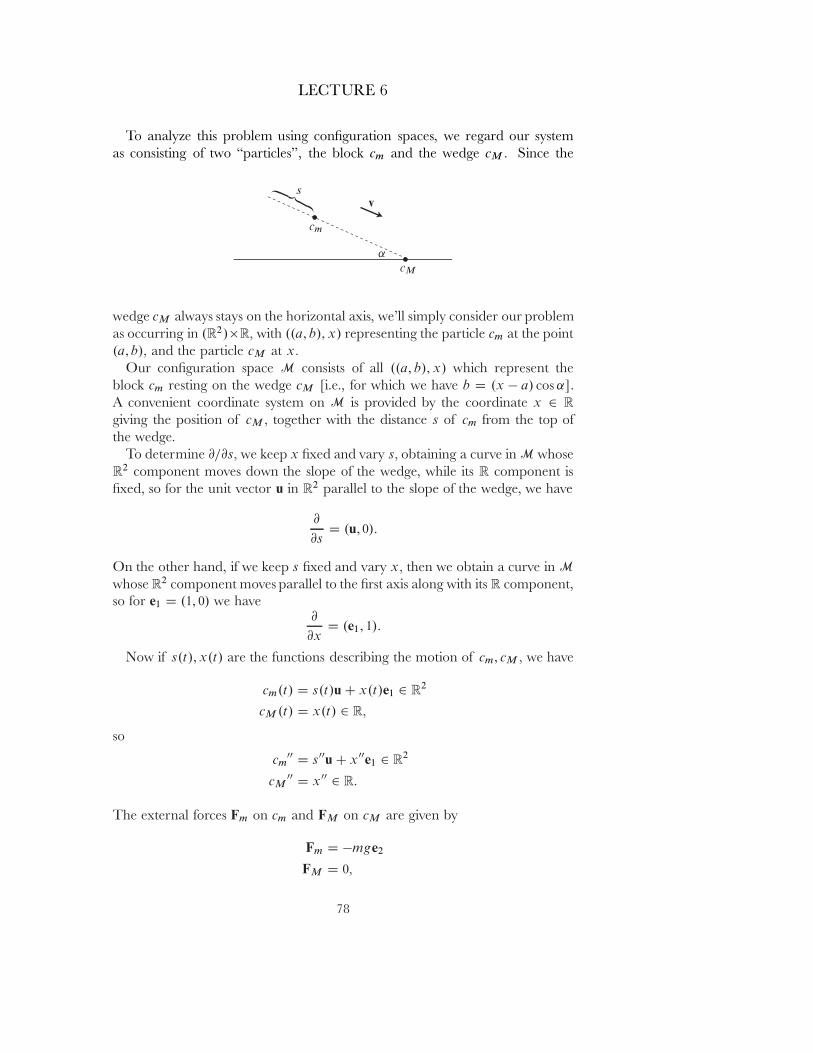
LECTURE 6
To analyze this problem using conˇguration spaces, we regard our systemas consisting of two \particles", the block cm and the wedge cM � Since the
wedge cM always stays on the horizontal axis, we'll simply consider our problemas occurring in .R2/�R� with ..a; b/; x/ representing the particle cm at the point.a; b/� and the particle cM at x�
Our conˇguration space M consists of all ..a; b/; x/ which represent theblock cm resting on the wedge cM [i.e., for which we have b D .x � a/ cos ˛].A convenient coordinate system on M is provided by the coordinate x 2 R
giving the position of cM � together with the distance s of cm from the top ofthe wedge.
To determine @=@s� we keep x ˇxed and vary s� obtaining a curve in M whoseR2 component moves down the slope of the wedge, while its R component isˇxed, so for the unit vector u in R2 parallel to the slope of the wedge, we have
@
@sD .u; 0/:
On the other hand, if we keep s ˇxed and vary x� then we obtain a curve in M
whose R2 component moves parallel to the ˇrst axis along with its R component,so for e1 D .1; 0/ we have
@
@xD .e1; 1/:
Now if s.t/; x.t/ are the functions describing the motion of cm; cM � we have
cm.t/ D s.t/u C x.t/e1 2 R2
cM .t/ D x.t/ 2 R�
so
cm00 D s00u C x00e1 2 R2
cM00 D x00 2 R:
The external forces Fm on cm and FM on cM are given by
Fm D �mge2
FM D 0�
78
LECTURE 6
so our condition for a solution is that
h�mge2 � mcm00; v1i C .0 � McM
00/ � v2 D 0
for all v D .v1; v2/ tangent to M� where h ; i is the usual inner product in theˇrst factor R2� while the inner product in the second factor R is just ordinarymultiplication. Choosing
v D@
@sD .u; 0/ and then v D
@
@xD .e1; 1/
gives the two equations
0 D h�mge2 � ms00u � mx00e1; ui � Mx00 � 0
0 D h�mge2 � ms00u � mx00e1; e1i � Mx00 � 1�
which amount to the equations
0 D mg sin ˛ � ms00 � mx00 cos ˛
0 D �ms00 cos ˛ � mx00 � Mx00:
Solving for x00 and s00 gives us the same results that we obtained previously,when they were called A and a� respectively. The ˇrst of the above equationsis precisely (1a), while the second is a combination of (1a), (1b), and (2).
Finally, let us consider the problem of rolling wheels. Physics books thatdiscuss rolling in any reasonably detailed way point out that rolling depends ona truly paradoxical fact: a wheel only rolls because of frictional forces, ones that\oppose sliding": a wheel not only displays the characteristics of our abstractrigid body, but it also has the strange feature that it is a˛ected by a frictionalforce that is exerted only at the (always changing) contact point of the wheel onthe inclined plane. To make the picture even more confusing, we can somehowignore this frictional force because, the physics books note, the path followedby any point on the circumference of the wheel has velocity 0 at the moment ithits the plane!
It is indeed well known that a cycloid, the path followed a point on the cir-cumference of a wheel, has velocity 0 at the point of contact. Physics booksseem to regard this as intuitively clear, but for those of us not endowed with therequisite physical intuition, here is a proof, for the general case of one surfacerolling on another.
79
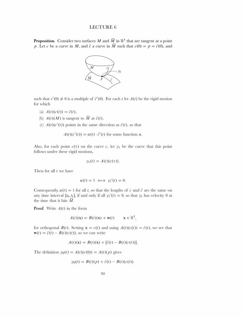
LECTURE 6
Proposition. Consider two surfaces M and SM in R3 that are tangent at a pointp� Let c be a curve in M� and Nc a curve in SM such that c.0/ D p D Nc.0/� and
such that c0.0/ 6D 0 is a multiple of Nc0.0/� For each t let A.t/ be the rigid motionfor which
(a) A.t/.c.t// D Nc.t/�
(b) A.t/.M/ is tangent to SM at Nc.t/�
(c) A.t/.c0.t// points in the same direction as Nc.t/� so that
A.t/.c0.t// D ˛.t/ � Nc0.t/ for some function ˛�
Also, for each point c.�/ on the curve c� let � be the curve that this pointfollows under these rigid motions,
� .t/ D A.t/.c.�//:
Then for all t we have
˛.t/ D 1 () t0.t/ D 0�
Consequently, ˛.t/ D 1 for all t� so that the lengths of c and Nc are the same onany time interval Œt0; t1�� if and only if all t
0.t/ D 0� so that t has velocity 0 atthe time that it hits SM�
Proof. Write A.t/ in the form
A.t/.x/ D B.t/.x/ C w.t/ x 2 R3�
for orthogonal B.t/� Setting x D c.t/ and using A.t/.c.t// D Nc.t/� we see thatw.t/ D Nc.t/ � B.t/.c.t//� so we can write
A.t/.x/ D B.t/.x/ C Œ Nc.t/ � B.t/.c.t//�:
The deˇnition 0.t/ D A.t/.c.0// D A.t/.p/ gives
0.t/ D B.t/.p/ C Nc.t/ � B.t/.c.t//:
80
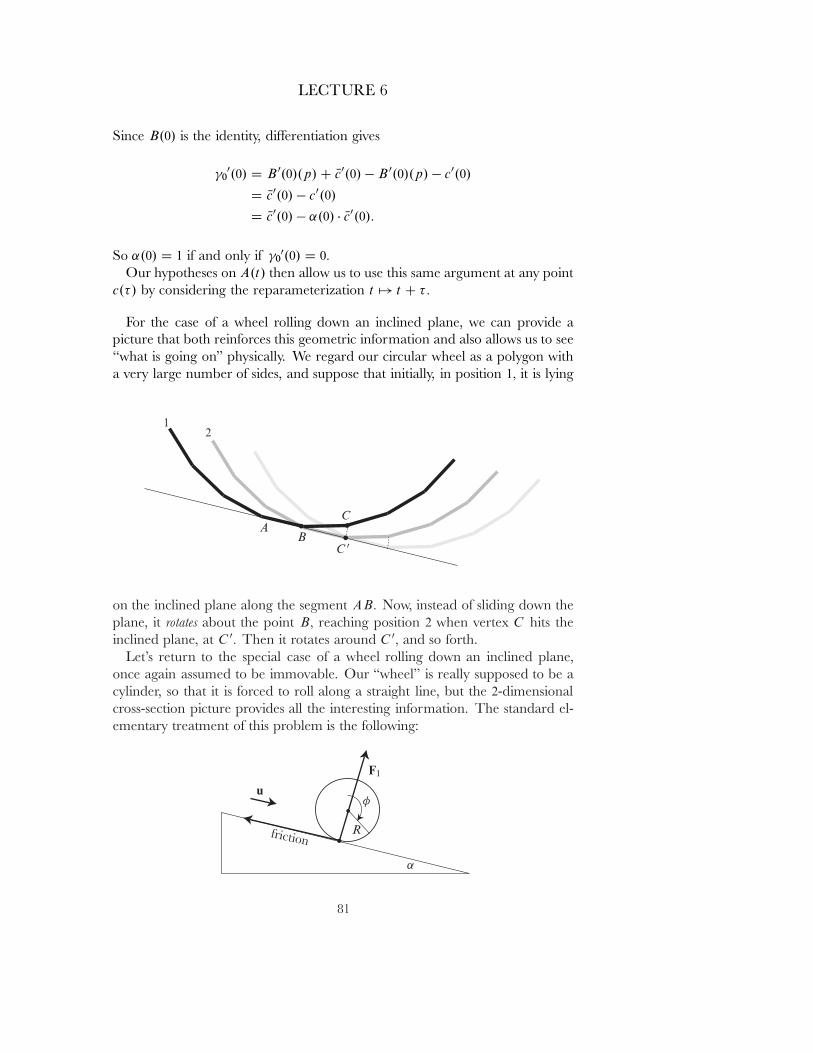
LECTURE 6
Since B.0/ is the identity, di˛erentiation gives
00.0/ D B 0.0/.p/ C Nc0.0/ � B 0.0/.p/ � c0.0/
D Nc0.0/ � c0.0/
D Nc0.0/ � ˛.0/ � Nc0.0/:
So ˛.0/ D 1 if and only if 00.0/ D 0�
Our hypotheses on A.t/ then allow us to use this same argument at any pointc.�/ by considering the reparameterization t 7! t C ��
For the case of a wheel rolling down an inclined plane, we can provide apicture that both reinforces this geometric information and also allows us to see\what is going on" physically. We regard our circular wheel as a polygon witha very large number of sides, and suppose that initially, in position 1� it is lying
on the inclined plane along the segment AB� Now, instead of sliding down theplane, it rotates about the point B� reaching position 2 when vertex C hits theinclined plane, at C 0� Then it rotates around C 0� and so forth.
Let's return to the special case of a wheel rolling down an inclined plane,once again assumed to be immovable. Our \wheel" is really supposed to be acylinder, so that it is forced to roll along a straight line, but the 2-dimensionalcross-section picture provides all the interesting information. The standard el-ementary treatment of this problem is the following:
81
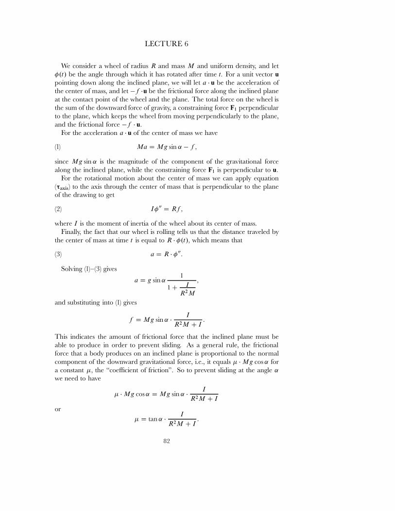
LECTURE 6
We consider a wheel of radius R and mass M and uniform density, and let�.t/ be the angle through which it has rotated after time t� For a unit vector upointing down along the inclined plane, we will let a � u be the acceleration ofthe center of mass, and let �f �u be the frictional force along the inclined planeat the contact point of the wheel and the plane. The total force on the wheel isthe sum of the downward force of gravity, a constraining force F1 perpendicularto the plane, which keeps the wheel from moving perpendicularly to the plane,and the frictional force �f � u�
For the acceleration a � u of the center of mass we have
(1) Ma D Mg sin ˛ � f �
since Mg sin ˛ is the magnitude of the component of the gravitational forcealong the inclined plane, while the constraining force F1 is perpendicular to u�
For the rotational motion about the center of mass we can apply equation(τaxis) to the axis through the center of mass that is perpendicular to the planeof the drawing to get
(2) I� 00 D Rf �
where I is the moment of inertia of the wheel about its center of mass.Finally, the fact that our wheel is rolling tells us that the distance traveled by
the center of mass at time t is equal to R � �.t/� which means that
(3) a D R � � 00:
Solving (1){(3) gives
a D g sin ˛1
1 C I
R2M
�
and substituting into (1) gives
f D Mg sin ˛ �I
R2M C I:
This indicates the amount of frictional force that the inclined plane must beable to produce in order to prevent sliding. As a general rule, the frictionalforce that a body produces on an inclined plane is proportional to the normalcomponent of the downward gravitational force, i.e., it equals � � Mg cos ˛ fora constant �� the \coeıcient of friction". So to prevent sliding at the angle ˛
we need to have
� � Mg cos ˛ D Mg sin ˛ �I
R2M C I
or� D tan ˛ �
I
R2M C I:
82

LECTURE 6
Thus we need a \perfectly rough" surface, with \� D 1" if we want to preventsliding at any angle.
For a homogeneous disc of radius R and mass M we easily compute thatI D 1
2 MR2� so we havea D 2
3 g sin ˛:
Thus the wheel rolls down the incline plane at only 2=3 of the speed that a blockslides down a frictionless inclined plane.
Even though a rolling wheel involves friction, it is still a natural candidatefor treatment by d'Alembert's principle, for the same reason that the standardelementary treatment ignores the e˛ect of friction: If we consider our wheel asa rigid body made up of a large collection of particles, and let v be any virtualinˇnitesimal displacement of the wheel, then the inner product hf ; vpi of thefrictional force f and the velocity vp at the point of contact p is always 0 since,as our Proposition shows, vp D 0�
Thus, the situation is quite like that of the compound pendulum. The onlyreal diıculty is that we have a sort of hybrid between our initial pendulum bobproblem, where we considered a single particle acted upon by a constraint force,and the compound pendulum, where almost all our constraints had alreadybeen considered in the analysis of rigid body motion. We really need to thinkof our wheel as representing two di˛erent \particles" s and � in R�
s D position of the center of mass� D angle through which wheel has turned,
having the respective masses
M D the total mass of the wheelI D the moment of inertia of the wheel.
We thus have a problem in R2 that is reduced to a problem on a 1-dimensionalsubmanifold M � R2 by the rolling condition
�.t/ D s.t/=R:
On M we have the obvious single coordinate s� the distance along the inclinedplane, and the corresponding tangent vector to M represents the pair
.1; 1=R/:
We are looking for a function s.t/ such that
.s.t/; �.t// D .s.t/; s.t/=R/
83
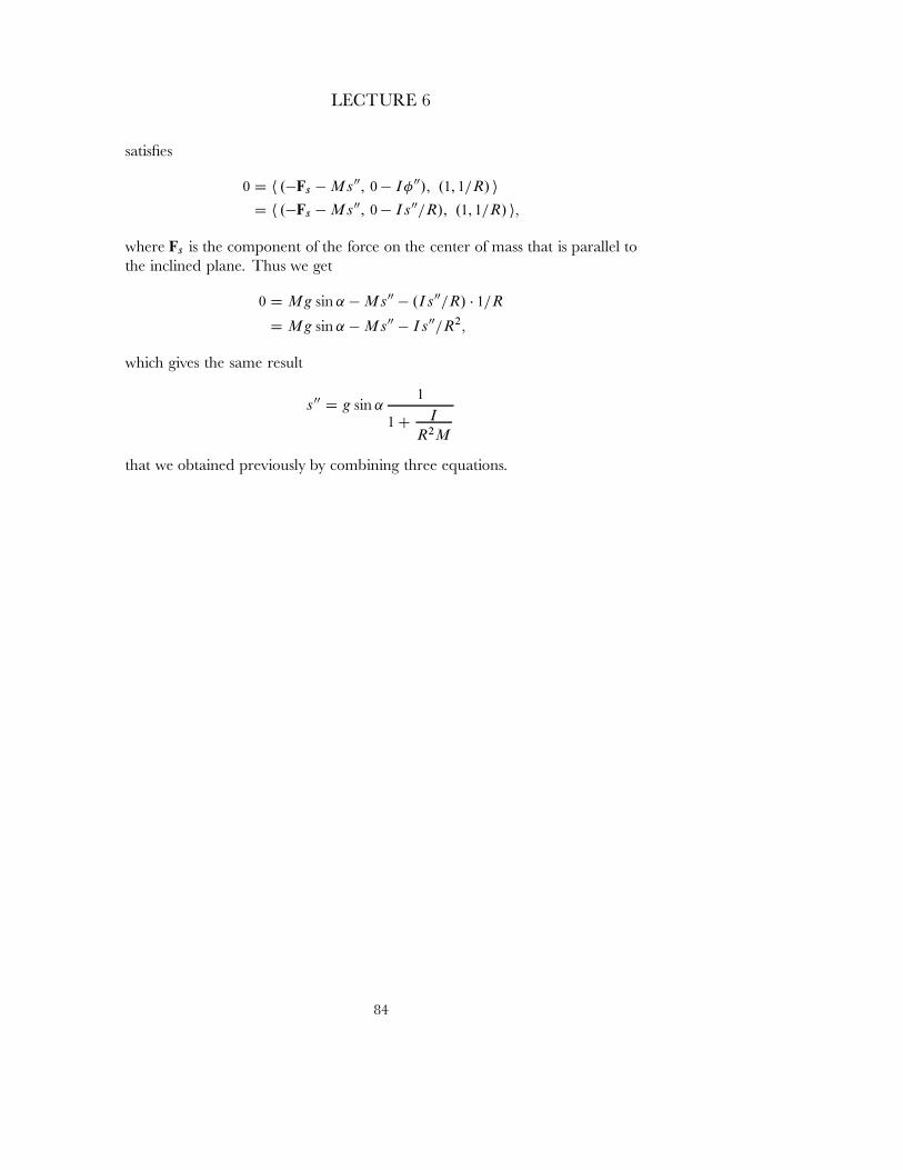
LECTURE 6
satisˇes
0 D h .�Fs � Ms00; 0 � I� 00/; .1; 1=R/ iD h .�Fs � Ms00; 0 � Is00=R/; .1; 1=R/ i�
where Fs is the component of the force on the center of mass that is parallel tothe inclined plane. Thus we get
0 D Mg sin ˛ � Ms00 � .Is00=R/ � 1=R
D Mg sin ˛ � Ms00 � Is00=R2�
which gives the same result
s00 D g sin ˛1
1 C I
R2M
that we obtained previously by combining three equations.
84
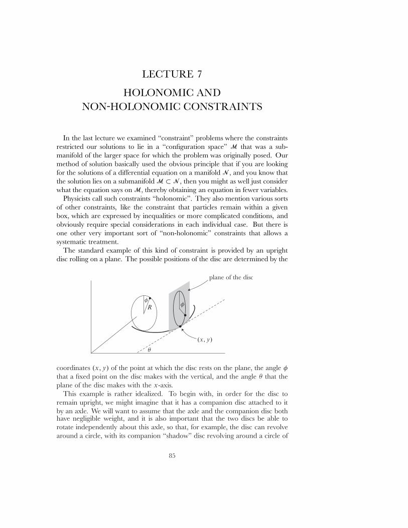
LECTURE 7
HOLONOMIC ANDNON©HOLONOMIC CONSTRAINTS
In the last lecture we examined \constraint" problems where the constraintsrestricted our solutions to lie in a \conˇguration space" M that was a sub-manifold of the larger space for which the problem was originally posed. Ourmethod of solution basically used the obvious principle that if you are lookingfor the solutions of a di˛erential equation on a manifold N � and you know thatthe solution lies on a submanifold M � N � then you might as well just considerwhat the equation says on M� thereby obtaining an equation in fewer variables.
Physicists call such constraints \holonomic". They also mention various sortsof other constraints, like the constraint that particles remain within a givenbox, which are expressed by inequalities or more complicated conditions, andobviously require special considerations in each individual case. But there isone other very important sort of \non-holonomic" constraints that allows asystematic treatment.
The standard example of this kind of constraint is provided by an uprightdisc rolling on a plane. The possible positions of the disc are determined by the
coordinates .x;y/ of the point at which the disc rests on the plane, the angle �
that a ˇxed point on the disc makes with the vertical, and the angle � that theplane of the disc makes with the x-axis.
This example is rather idealized. To begin with, in order for the disc toremain upright, we might imagine that it has a companion disc attached to itby an axle. We will want to assume that the axle and the companion disc bothhave negligible weight, and it is also important that the two discs be able torotate independently about this axle, so that, for example, the disc can revolvearound a circle, with its companion \shadow" disc revolving around a circle of
85
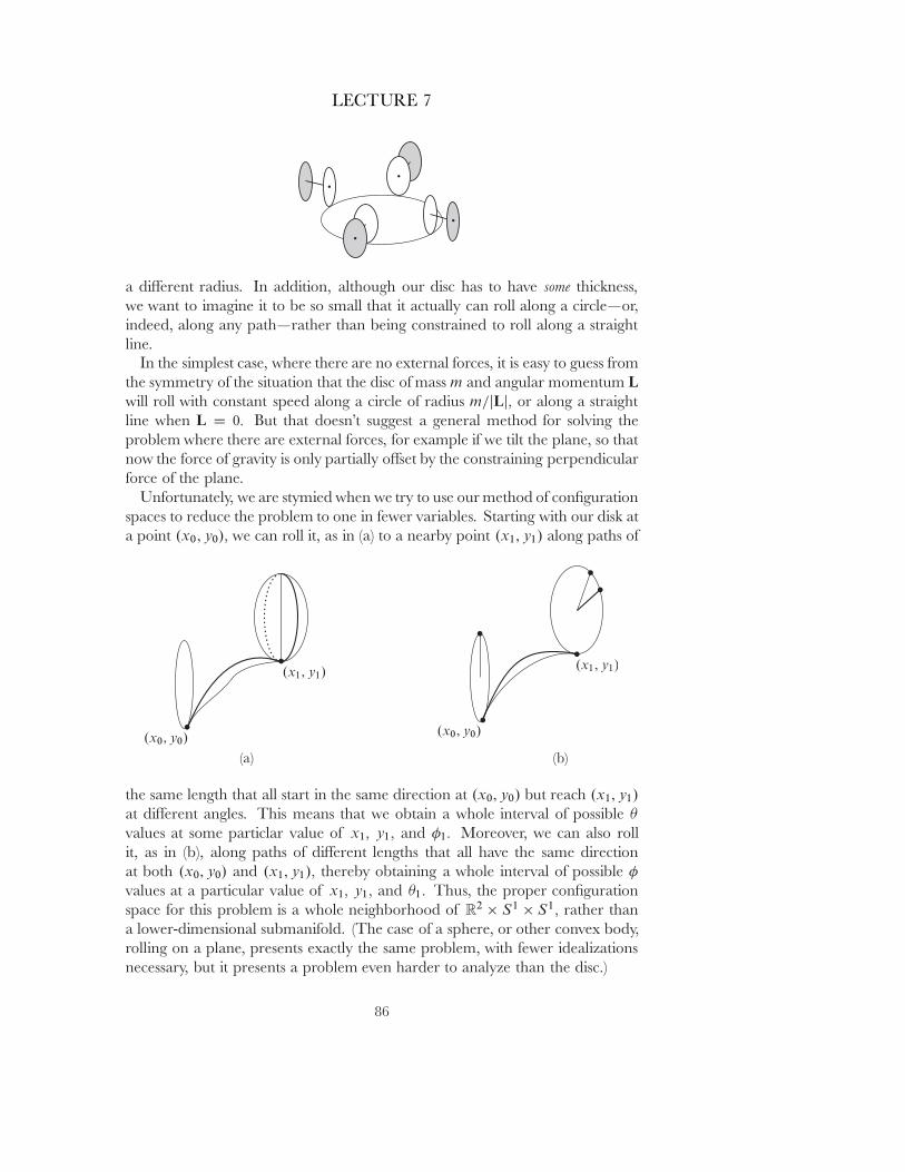
LECTURE 7
a di˛erent radius. In addition, although our disc has to have some thickness,we want to imagine it to be so small that it actually can roll along a circle|or,indeed, along any path|rather than being constrained to roll along a straightline.
In the simplest case, where there are no external forces, it is easy to guess fromthe symmetry of the situation that the disc of mass m and angular momentum Lwill roll with constant speed along a circle of radius m=jLj� or along a straightline when L D 0� But that doesn't suggest a general method for solving theproblem where there are external forces, for example if we tilt the plane, so thatnow the force of gravity is only partially o˛set by the constraining perpendicularforce of the plane.
Unfortunately, we are stymied when we try to use our method of conˇgurationspaces to reduce the problem to one in fewer variables. Starting with our disk ata point .x0; y0/� we can roll it, as in (a) to a nearby point .x1; y1/ along paths of
the same length that all start in the same direction at .x0; y0/ but reach .x1; y1/
at di˛erent angles. This means that we obtain a whole interval of possible �
values at some particlar value of x1� y1� and �1� Moreover, we can also rollit, as in (b), along paths of di˛erent lengths that all have the same directionat both .x0; y0/ and .x1; y1/� thereby obtaining a whole interval of possible �
values at a particular value of x1� y1� and �1� Thus, the proper conˇgurationspace for this problem is a whole neighborhood of R2 � S1 � S1� rather thana lower-dimensional submanifold. (The case of a sphere, or other convex body,rolling on a plane, presents exactly the same problem, with fewer idealizationsnecessary, but it presents a problem even harder to analyze than the disc.)
86
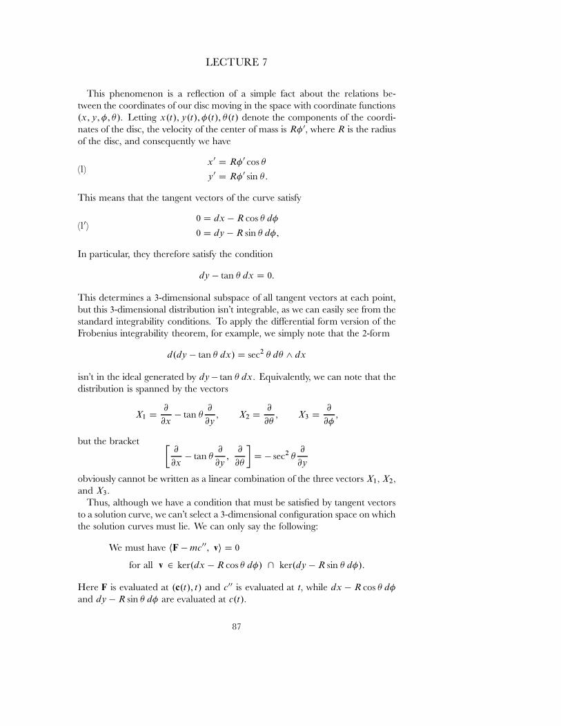
LECTURE 7
This phenomenon is a re ection of a simple fact about the relations be-tween the coordinates of our disc moving in the space with coordinate functions.x;y; �; �/� Letting x.t/; y.t/; �.t/; �.t/ denote the components of the coordi-nates of the disc, the velocity of the center of mass is R� 0� where R is the radiusof the disc, and consequently we have
(1)x0 D R� 0 cos �
y 0 D R� 0 sin �:
This means that the tangent vectors of the curve satisfy
(10)0 D dx � R cos � d�
0 D dy � R sin � d�;
In particular, they therefore satisfy the condition
dy � tan � dx D 0:
This determines a 3-dimensional subspace of all tangent vectors at each point,but this 3-dimensional distribution isn't integrable, as we can easily see from thestandard integrability conditions. To apply the di˛erential form version of theFrobenius integrability theorem, for example, we simply note that the 2-form
d.dy � tan � dx/ D sec2 � d� ^ dx
isn't in the ideal generated by dy � tan � dx� Equivalently, we can note that thedistribution is spanned by the vectors
X1 D@
@x� tan �
@
@y� X2 D
@
@�� X3 D
@
@��
but the bracket �@
@x� tan �
@
@y;
@
@�
�D � sec2 �
@
@y
obviously cannot be written as a linear combination of the three vectors X1� X2�
and X3�
Thus, although we have a condition that must be satisˇed by tangent vectorsto a solution curve, we can't select a 3-dimensional conˇguration space on whichthe solution curves must lie. We can only say the following:
We must have hF � mc00; vi D 0
for all v 2 ker.dx � R cos � d�/ \ ker.dy � R sin � d�/:
Here F is evaluated at .c.t/; t/ and c00 is evaluated at t� while dx � R cos � d�
and dy � R sin � d� are evaluated at c.t/�
87
LECTURE 7
More generally, if the conditions in (10) are replaced by the vanishing of certain1-forms !1; : : : ;!L� then
We must have hF � mc00; vi D 0
for all v 2 ker !1 \ � � � \ ker !L:
In terms of the linear functional
ˆ.v/ D hF � mc00; vi
this condition says that
ker ˆ � ker !1 \ � � � \ ker !L:
We can now appeal to the very same vector space fact was used in our proof ofthe Principle of Virtual Work, in Lecture 5, and conclude, applying the argu-ment at each point, that
ˆ D �1!1 C � � � C �L!L
for some functions �1; : : : ; �L� known as Lagrange multipliers. This leads us to thefollowing criterion for solutions:
d'Alembert's Principle for Di˛erential Constraints: If the constraintson a system require the tangent vector of the motion to lie in thesubspace ker.!1/ \ � � � \ ker.!L/� then there are Lagrange multipli-ers �1; : : : ; �L such that the motions of the system under the externalforces F satisfy
hF � mc00; vi D �1!1.v/ C � � � C �L!L.v/
for all tangent vectors v at c�
To apply this to the problem of an upright disc rolling on a plane, where wehave the relations
(1)x0 D R� 0 cos �
y 0 D R� 0 sin �:
and
(10)0 D dx � R cos � d�
0 D dy � R sin � d�;
we note that, as in the case of the rolling wheel, we are not dealing with asingle particle c.t/; in the present situation we have to think of the disc as threedi˛erent \particles", the particle .x; y/ with mass M� the particle � with mass I�
88
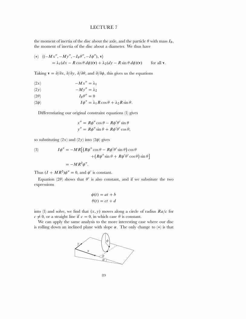
LECTURE 7
the moment of inertia of the disc about the axle, and the particle � with mass I� �
the moment of inertia of the disc about a diameter. We thus have
h.�Mx00; �My 00;�I� � 00; �I� 00/; vi(�)D �1.dx � R cos � d�/.v/ C �2.dy � R sin � d�/.v/ for all v�
Taking v D @=@x� @=@y� @=@�� and @=@�� this gives us the equations
�Mx00 D �1(2x)�My 00 D �2(2y)
I�� 00 D 0(2� )I� 00 D �1R cos � C �2R sin �:(2�)
Di˛erentiating our original constraint equations (1) gives
x00 D R� 00 cos � � R� 0� 0 sin �
y 00 D R� 00 sin � C R� 0� 0 cos ��
so substituting (2x) and (2y) into (2�) gives
I� 00 D �MR��
R� 00 cos � � R� 0� 0 sin ��cos �(3)
C�R� 00 sin � C R� 0� 0 cos �
�sin �
�
D �MR2� 00:
Thus .I C MR2/� 00 D 0� and � 0 is constant.
Equation (2� ) shows that � 0 is also constant, and if we substitute the twoexpressions
�.t/ D at C b
�.t/ D ct C d
into (1) and solve, we ˇnd that .x;y/ moves along a circle of radius Ra=c forc 6D 0� or a straight line if c D 0� in which case � is constant.
We can apply the same analysis to the more interesting case where our discis rolling down an inclined plane with slope ˛� The only change to (�) is that
89
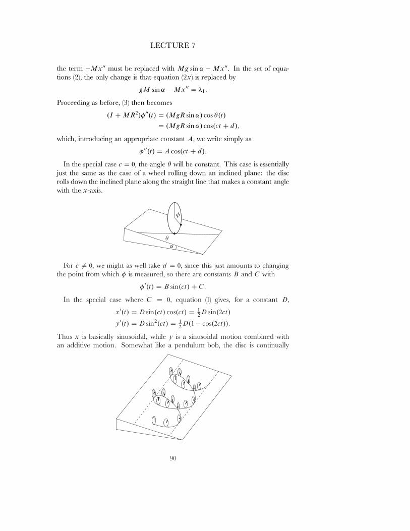
LECTURE 7
the term �Mx00 must be replaced with Mg sin ˛ � Mx00� In the set of equa-tions (2), the only change is that equation (2x) is replaced by
gM sin ˛ � Mx00 D �1:
Proceeding as before, (3) then becomes
.I C MR2/� 00.t/ D .MgR sin ˛/ cos �.t/
D .MgR sin ˛/ cos.ct C d/�
which, introducing an appropriate constant A� we write simply as
� 00.t/ D A cos.ct C d/:
In the special case c D 0� the angle � will be constant. This case is essentiallyjust the same as the case of a wheel rolling down an inclined plane: the discrolls down the inclined plane along the straight line that makes a constant anglewith the x-axis.
For c 6D 0� we might as well take d D 0� since this just amounts to changingthe point from which � is measured, so there are constants B and C with
� 0.t/ D B sin.ct/ C C:
In the special case where C D 0� equation (1) gives, for a constant D�
x0.t/ D D sin.ct/ cos.ct/ D 12 D sin.2ct/
y 0.t/ D D sin2.ct/ D 12 D.1 � cos.2ct//:
Thus x is basically sinusoidal, while y is a sinusoidal motion combined withan additive motion. Somewhat like a pendulum bob, the disc is continually
90
LECTURE 7
interchanging potential energy and kinetic energy. At the lowest points of thetrajectory, where the kinetic energy is greatest, the disc is moving parallel tothe y-axis, where it has just enough kinetic energy to propel it back up to thehighest level.
More generally, we have constants E and F with
x0 D E sin.2ct/ C F cos.ct/
y 0 D E.1 � cos.2ct// C F sin.ct/�
and if you have a nice computer program for producing graphs you can ˇndout what the most general solution looks like.
The Lagrange multiplies �i that occur in d'Alembert's principle for di˛er-ential constraints may seem to have appeared out of the blue, but they can beinterpreted in terms of the constraint forces C on our system S� In fact, considertwo systems:
(a) the system S with constraints C and external forces F�
(b) the system S with no constraints and external forces F C C�
The systems (a) and (b) obviously have the same solutions. But the solutionsto (a) satisfy
hF � mc00; vi D �1!1.v/ C � � � C �L!L.v/ for all v�
while the solutions to (b) satisfy
hF C C � mc00; vi D 0 for all v;
subtracting the ˇrst equation from the second, we ˇnd that we must have
hC; vi D �.�1!1 C � � � C �L!L/.v/ for all v�
By writing out �1!1 C � � � C �L!L in terms of the coordinates, we can then ˇndall the components of C�
For example, in our original problem of the disc rolling on a horizontal plane,where we have
�1!1 C �2!2 D �1.dx � R cos � d�/ C �2.dy � R cos sin � d�/
D �1 dx C �2 dy � .�1R cos � C �2R sin �/ d�
we ˇnd that the components Cx and Cy are given by
Cx D hC; @=@xi D ��1
Cy D hC; @=@yi D ��2
C� D hC; @=@�i D 0
C� D hC; @=@�i D R.�1 cos � C �2 sin �/:
91
LECTURE 7
Thus, the constraint forces can be found in terms of �1 and �2� which wecan determine from (2x) and (2y) once we've solved explicitly for x.t/ andy.t/� The x and y components together, the vector .x00.t/; y 00.t//� representsthe constraint force on our \particle" .x.t/; y.t//� and thus the frictional forceexerted by the plane to keep the center of mass in its circular orbit. Since thecenter of mass moves in a circle with constant angular velocity, .x00.t/; y 00.t//is always perpendicular to the velocity vector v D .x0.t/; y 0.t// of the center ofmass, as we would expect.
The � component of the constraints,�R.x00 cos � C y 00 sin �/�
represents the constraint force on our \particle" �� the frictional force exertedby the plane against the direction of �; it is the additional frictional force, inthe direction of the velocity vector, that is needed to insure that the wheel rolls.
In the case of holonomic constraints, we didn't need to use the Lagrange mul-tipliers �i � but we can use them, if we want to obtain the constraint forces. Forexample, consider the rolling wheel problem, which we treated by the methodof conˇguration spaces on page 83. Now we will simply use the coordinates s
and � and the relations0.t/ D R� 0.t/
between their derivatives. We then have the following condition for all v:hMg sin ˛ � Ms00 � I� 00; vi D �.ds � Rd�/.v/:
Taking v D @=@s and then v D @=@� we getMg sin ˛ � Ms00 D �(a)
�I� 00 D �R��(b)so
Mg sin ˛ � Ms00 DI
R� 00
and di˛erentiating the constraint s0 D R� 0 gives s00 D R� 00� so this becomes
Mg sin ˛ � Ms00 DI
R2s00�
with the same solutions00 D g sin ˛
1
1 C I
R2Mas before. Substituting back into (a) then gives
� D Mg sin ˛I
R2M C I�
which agrees with the formula for the frictional force f on page 82.Of course, we can easily formulate and use a \mixed" version of d'Alembert's
principle, where some of the constraints restrict our system to lie in a conˇgu-ration space M� while other constraints restrict the tangent vector of the systemto be in the kernels of various 1-forms.
92
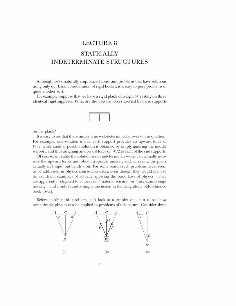
LECTURE 8
STATICALLYINDETERMINATE STRUCTURES
Although we've naturally emphasized constraint problems that have solutionsusing only our basic consideration of rigid bodies, it is easy to pose problems ofquite another sort.
For example, suppose that we have a rigid plank of weight W resting on threeidentical rigid supports. What are the upward forces exerted by these supports
on the plank?It is easy to see that there simply is no well-determined answer to this question.
For example, one solution is that each support provides an upward force ofW=3� while another possible solution is obtained by simply ignoring the middlesupport, and thus assigning an upward force of W=2 to each of the end supports.
Of course, in reality the solution is not indeterminate|one can actually mea-sure the upward forces and obtain a speciˇc answer; and, in reality, the plankactually isn't rigid, but bends a bit. For some reason such problems never seemto be addressed in physics course nowadays, even though they would seem tobe wonderful examples of actually applying the basic laws of physics. Theyare apparently relegated to courses on \material science" or \mechanical engi-neering", and I only found a simple discussion in the delightfully old-fashionedbook [S-G].
Before tackling this problem, let's look at a simpler one, just to see howsome simple physics can be applied to problems of this nature. Consider three
93
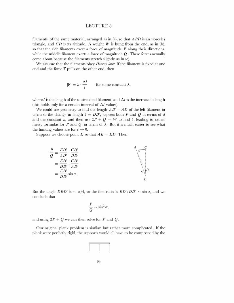
LECTURE 8
ˇlaments, of the same material, arranged as in (a), so that ABD is an isoscelestriangle, and CD is its altitude. A weight W is hung from the end, as in (b),so that the side ˇlaments exert a force of magnitude P along their directions,while the middle ˇlament exerts a force of magnitude Q� These forces actuallycome about because the ˇlaments stretch slightly as in (c).
We assume that the ˇlaments obey Hooke's law: If the ˇlament is ˇxed at oneend and the force F pulls on the other end, then
jFj D � ��l
lfor some constant ��
where l is the length of the unstretched ˇlament, and �l is the increase in length(this holds only for a certain interval of �l values).
We could use geometry to ˇnd the length AD0 � AD of the left ˇlament interms of the change in length ı D DD0� express both P and Q in terms of ı
and the constant �� and then use 2P C Q D W to ˇnd ı� leading to rathermessy formulas for P and Q� in terms of �� But it is much easier to see whatthe limiting values are for " ! 0�
Suppose we choose point E so that AE D ED� Then
P
QD
ED0
AD0 �CD0
DD0
DED0
DD0 �CD0
AD0
DED0
DD0 sin ˛:
But the angle DED0 is � �=4� so the ˇrst ratio is ED0=DD0 � sin ˛� and weconclude that
P
Q� sin2 ˛�
and using 2P C Q we can then solve for P and Q�
Our original plank problem is similar, but rather more complicated. If theplank were perfectly rigid, the supports would all have to be compressed by the
94
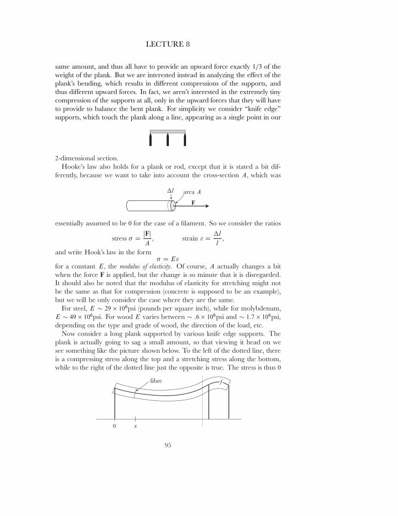
LECTURE 8
same amount, and thus all have to provide an upward force exactly 1=3 of theweight of the plank. But we are interested instead in analyzing the e˛ect of theplank's bending, which results in di˛erent compressions of the supports, andthus di˛erent upward forces. In fact, we aren't interested in the extremely tinycompression of the supports at all, only in the upward forces that they will haveto provide to balance the bent plank. For simplicity we consider \knife edge"supports, which touch the plank along a line, appearing as a single point in our
2-dimensional section.Hooke's law also holds for a plank or rod, except that it is stated a bit dif-
ferently, because we want to take into account the cross-section A� which was
essentially assumed to be 0 for the case of a ˇlament. So we consider the ratios
stress � DjFjA
� strain " D�l
l�
and write Hook's law in the form� D E"
for a constant E� the modulus of elasticity. Of course, A actually changes a bitwhen the force F is applied, but the change is so minute that it is disregarded.It should also be noted that the modulus of elasticity for stretching might notbe the same as that for compression (concrete is supposed to be an example),but we will be only consider the case where they are the same.
For steel, E � 29 � 106psi (pounds per square inch), while for molybdenum,E � 49 � 106psi� For wood E varies between � :6 � 106psi and � 1:7 � 106psi�depending on the type and grade of wood, the direction of the load, etc.
Now consider a long plank supported by various knife edge supports. Theplank is actually going to sag a small amount, so that viewing it head on wesee something like the picture shown below. To the left of the dotted line, thereis a compressing stress along the top and a stretching stress along the bottom,while to the right of the dotted line just the opposite is true. The stress is thus 0
95

LECTURE 8
at some intermediate surface, the neutral plane, whose proˇle, shown as a heavyline in the ˇgure, is the graph of some function f� The ˇgure also shows a crosssection of the \ˇbre" through .x;f .x//� that is, the surface into which a verticalsection of the plank is deformed.
The ˇgure below is a greatly enlarged view of a small portion of the ˇgurenear the point .x; f .x//� bounded by two ˇbres. While the heavy line is the
graph of f� the cross-section of the neutral plane, the dotted line indicates thecross-section of a surface where the stress has the constant value y� The wholeregion is ˇlled up by such surfaces having values in some interval .y0; y1/�
Let the curvature of the graph of f at the point .x; f .x// be �.x/� where wehave
�.x/ Df 00.x/
1 C .f 0.x//2:
Near the point .x; f .x//� the graph is very close to a segment of a circle sub-tending an angle � with radius R D 1=.��/� where the minus sign is necessarybecause f 00 � 0 at this point. So the solid line and the dotted line have lengths �
and �0 given, to ˇrst order, by
� D R�
�0 D .R C y/��
Consequently, the strain " along the surface indicated by the dotted line is givenby
" D�0 � �
�D
y�
R�D
y
RD �y��
96
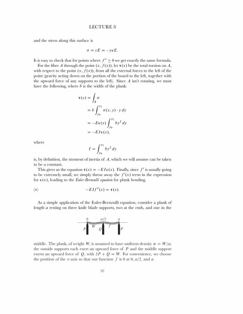
LECTURE 8
and the stress along this surface is
� D "E D �y�E:
It is easy to check that for points where f 00 � 0 we get exactly the same formula.For the ˇbre A through the point .x; f .x//� let τ.x/ be the total torsion on A�
with respect to the point .x; f .x//� from all the external forces to the left of thepoint (gravity acting down on the portion of the board to the left, together withthe upward force of any supports to the left). Since A isn't rotating, we musthave the following, where b is the width of the plank:
τ.x/ DZ
A
�
D b
Z y1
y0
�.x; y/ � y dy
D �E�.x/
Z y1
y0
by2 dy
D �EI�.x/�
where
I DZ y1
y0
by2 dy
is, by deˇnition, the moment of inertia of A� which we will assume can be takento be a constant.
This gives us the equation τ.x/ D �EI�.x/� Finally, since f 0 is usually goingto be extremely small, we simply throw away the f 0.x/ term in the expressionfor �.x/� leading to the Euler-Bernoulli equation for plank bending,
(�) �EIf 00.x/ D τ.x/:
As a simple application of the Euler-Bernoulli equation, consider a plank oflength a resting on three knife blade supports, two at the ends, and one in the
middle. The plank, of weight W� is assumed to have uniform density w D W=a;the outside supports each exert an upward force of P and the middle supportexerts an upward force of Q� with 2P C Q D W� For convenience, we choosethe position of the x-axis so that our function f is 0 at 0� a=2� and a�
97
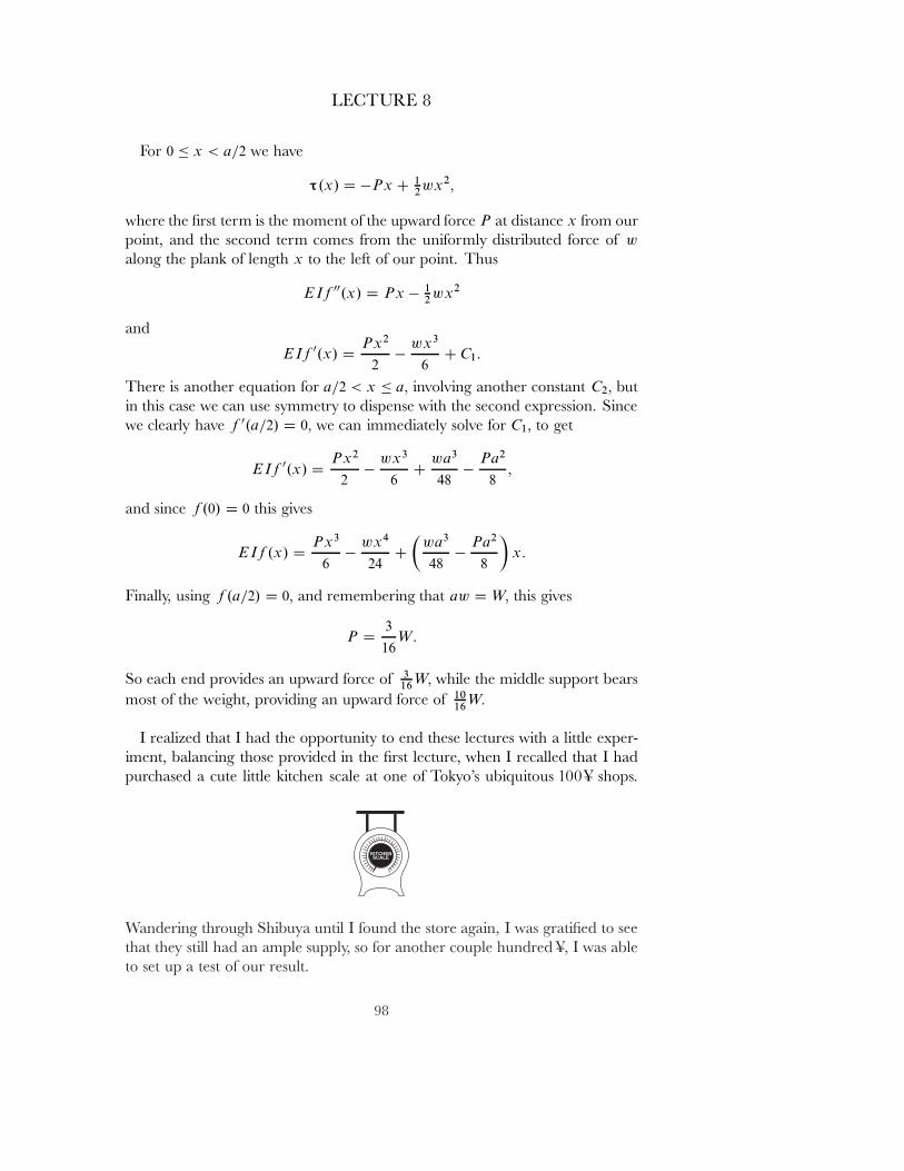
LECTURE 8
For 0 � x < a=2 we have
τ.x/ D �Px C 12 wx2�
where the ˇrst term is the moment of the upward force P at distance x from ourpoint, and the second term comes from the uniformly distributed force of w
along the plank of length x to the left of our point. Thus
EIf 00.x/ D Px � 12 wx2
and
EIf 0.x/ DPx2
2�
wx3
6C C1:
There is another equation for a=2 < x � a� involving another constant C2� butin this case we can use symmetry to dispense with the second expression. Sincewe clearly have f 0.a=2/ D 0� we can immediately solve for C1� to get
EIf 0.x/ DPx2
2�
wx3
6C
wa3
48�
Pa2
8�
and since f .0/ D 0 this gives
EIf .x/ DPx3
6�
wx4
24C�
wa3
48�
Pa2
8
�x:
Finally, using f .a=2/ D 0� and remembering that aw D W� this gives
P D3
16W:
So each end provides an upward force of 316 W� while the middle support bears
most of the weight, providing an upward force of 1016 W�
I realized that I had the opportunity to end these lectures with a little exper-iment, balancing those provided in the ˇrst lecture, when I recalled that I hadpurchased a cute little kitchen scale at one of Tokyo's ubiquitous 100 Ç shops.
Wandering through Shibuya until I found the store again, I was gratiˇed to seethat they still had an ample supply, so for another couple hundred Ç, I was ableto set up a test of our result.
98
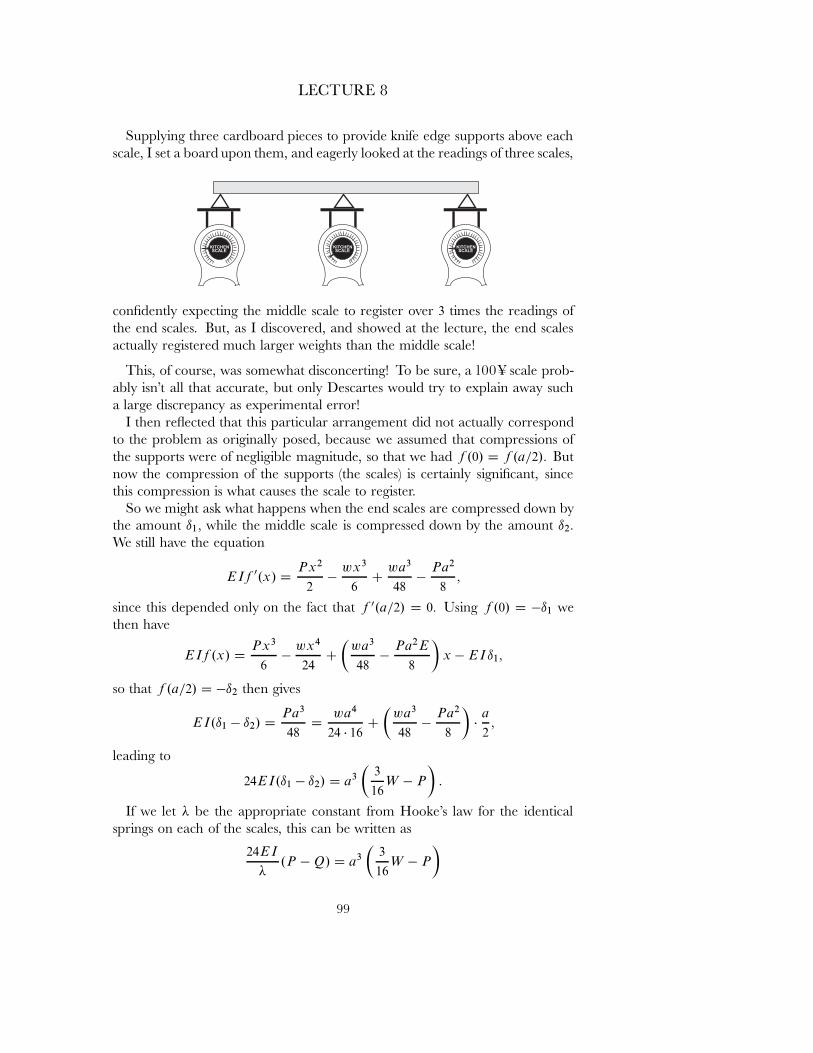
LECTURE 8
Supplying three cardboard pieces to provide knife edge supports above eachscale, I set a board upon them, and eagerly looked at the readings of three scales,
conˇdently expecting the middle scale to register over 3 times the readings ofthe end scales. But, as I discovered, and showed at the lecture, the end scalesactually registered much larger weights than the middle scale!
This, of course, was somewhat disconcerting! To be sure, a 100 Ç scale prob-ably isn't all that accurate, but only Descartes would try to explain away sucha large discrepancy as experimental error!
I then re ected that this particular arrangement did not actually correspondto the problem as originally posed, because we assumed that compressions ofthe supports were of negligible magnitude, so that we had f .0/ D f .a=2/� Butnow the compression of the supports (the scales) is certainly signiˇcant, sincethis compression is what causes the scale to register.
So we might ask what happens when the end scales are compressed down bythe amount ı1� while the middle scale is compressed down by the amount ı2�
We still have the equation
EIf 0.x/ DPx2
2�
wx3
6C
wa3
48�
Pa2
8�
since this depended only on the fact that f 0.a=2/ D 0� Using f .0/ D �ı1 wethen have
EIf .x/ DPx3
6�
wx4
24C�
wa3
48�
Pa2E
8
�x � EIı1�
so that f .a=2/ D �ı2 then gives
EI.ı1 � ı2/ DPa3
48D
wa4
24 � 16C�
wa3
48�
Pa2
8
��
a
2�
leading to
24EI.ı1 � ı2/ D a3�
3
16W � P
�:
If we let � be the appropriate constant from Hooke's law for the identicalsprings on each of the scales, this can be written as
24EI
�.P � Q/ D a3
�3
16W � P
�
99
LECTURE 8
or24EI
�.3P � W / D a2
�3
16W � P
�:
Of course, it's the ratio P=W that interest us, so we write
24EI
�
�P
W� 1
�D a3
�3
16�
P
W
�
which we can solve as
P
WD
3a3
16C
24EI
�
a3 C72EI
�
:
Now this result at least seems reasonable at the extreme values for �: If �
is very large (so that the springs on the scale are extremely strong, and conse-quently their compression is very tiny), then we get the answer
P
W�
3
16
obtained previously, when we assumed no compression at all. On the otherhand, if � is very small, we get
P
W�
1
3�
i.e., the weight is distributed nearly equally among the supports.However it seemed very unlikely that I would get an answer anywhere close
to the results of the experiment if I inserted the proper value of � (determinedeasily enough by seeing how far down a scale was depressed when it registereda particular weight), because even for a piece of wood, E is enormous, on theorder of 106� so the formula would just give P
W� 1
3 �
So I ended this series of lectures confessing my inability to provide a goodanswer for this ˇnal problem. Perhaps some day I'll be able to persuade amechanical engineer to sit down and explain to a mathematician just how thisproblem really should be handled.
� THE END �
100
REFERENCES
[A] V. I. Arnol'd, Huygens and Barrow, Newton and Hooke, Birkh�auser Verlag, 1990.
[D] R. Dugas, A History of Mechanics, �Editions du Gri˛on, 1955. Translated byJ. R. Maddox. Reproduced by Dover Publications, Inc., 1988.
[Fey] R. P. Feynman, R. B. Leighton, and M. Sands, The Feynman Lectures onPhysics, Volume 1, Addison-Wesley Publishing Company, Inc., 1963.
[Fr] A. P. French, Newtonian Mechanics, W. W. Norton & Company, Inc., 1971.[Go] H. Goldsmith, Classical Mechanics, Addison-Wesley Publishing Company,
Inc., 1950.[Gu] N. Guicciardini, \Johann Bernoulli, John Keill and the inverse problem
of central forces", Ann. of Sci. 52 (6) (1995), 537{575.[H] W. R. Hamilton, \On the Composition of Forces", Proc. Royal Irish Acad.
2 (1844), 166{170. Also available in The Mathematical Papers of Sir WilliamRowan Hamilton, volume 2, Cambridge University Press, 1931.
[L] P. S. Laplace, Trait�e de M�ecanique C�eleste, Duprat, Paris, 1798.[M] E. Mach, The Science of Mechanics. Translated by T. J. McCormack, 6th ed.,
The Open Court Publishing Company, 1960.[M-T-W] C. W. Misner, K. S. Thorne, and J. A. Wheeler, Gravitation, W. H.
Freeman and Company, 1973.[N-C-W] I. Newton, The Principia. Translated by I. B. Cohen and A. Whitman,
University of California Press, 1999.[N-H-T] The Correspondence of Isaac Newton, A. R. Hall and L. Tilling, eds., Cam-
bridge University Press, 1959{1977.[N-L] H. V. Neher and R. B. Leighton, Amer. Jour. of Phys. 31, 225 (1963).[P] P. S. Poisson, Trait�e de M�ecanique, Bachelier, Paris, 1833.[S-G] J. Synge and B. Griıth, Principles of Mechanics, 3rd ed., McGraw-Hill,
1959.
101