elevatedstoragetank standards dec2012
DESCRIPTION
elevated water tankTRANSCRIPT
DWU Elevated Storage Tank and Ground Storage Tank Design Standards October 2012
EELLEEVVAATTEEDD SSTTOORRAAGGEE TTAANNKK && GGRROOUUNNDD SSTTOORRAAGGEE TTAANNKK
DDEESSIIGGNN MMAANNUUAALL
December 2012
DWU Elevated Storage Tank and Ground Storage Tank Design Standards December 2012
1
TABLE OF CONTENTS PREFACE ACKNOWLEDGEMENTS ...................................................................................................... 3
INTRODUCTION .................................................................................................................. 4
CHAPTER 1 – ELEVATED STORAGE TANK DESIGN GUIDELINES
REFERENCES ...................................................................................................................... 5
FACILITY SITING ............................................................................................................... 7
VEHICULAR ACCESS ......................................................................................................... 7
SECURITY ACCESS AND SURVEILLANCE .............................................................................7
DRAINAGE .......................................................................................................................... 8
TANK DESIGN .................................................................................................................... 8
SCADA ............................................................................................................................ 15
DISINFECTION .................................................................................................................. 15
QUALITY ASSURANCE .......................................................................................................16
WARRANTY ........................................................................................................................16
ACCEPTANCE .................................................................................................................... 16
ADMINISTRATIVE ..............................................................................................................17
CHAPTER 2 – GROUND STORAGE TANK DESIGN GUIDELINES
REFERENCES .................................................................................................................... 18
FACILITY SITING ............................................................................................................. 20
VEHICULAR ACCESS ....................................................................................................... 20
SECURITY ACCESS AND SURVEILLANCE .......................................................................... 20
DRAINAGE ........................................................................................................................ 21
TANK DESIGN .................................................................................................................. 21
SCADA ............................................................................................................................ 24
DISINFECTION .................................................................................................................. 24
QUALITY ASSURANCE .......................................................................................................24
DWU Elevated Storage Tank and Ground Storage Tank Design Standards December 2012
2
WARRANTY ........................................................................................................................25
ACCEPTANCE .................................................................................................................... 25
ADMINISTRATIVE ..............................................................................................................25
APPENDIX
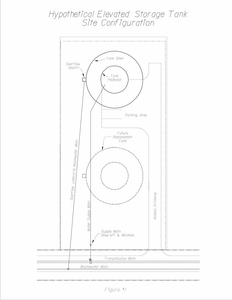
HYPOTHETICAL ELEVATED TANK SITE CONFIGURATION ............................... FIGURE #1
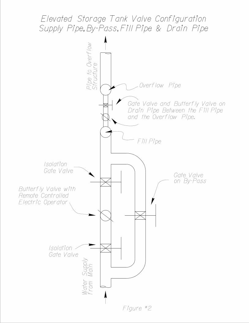
ELEVATED STORAGE TANK VALVE CONFIGURATION ..................................... FIGURE #2
DWU Elevated Storage Tank Design Standards December 2012
3
PREFACE ACKNOWLEDGMENTS:
This manual is the first edition design manual outlining the minimum design criteria for elevated storage tanks and ground storage tanks for use within the Dallas Water Utilities distribution and transmission network. Principal Editors: Raymond Keprta, P.E., Engineering Services, Dallas Water Utilities Chad Kopecki, P.E., Engineering Services Dallas Water Utilities Technical Reviewers: Rick Zhone, P.E., Water Facilities Project Management, Dallas Water Utilities Darrell Engelbrecht, P.E., Water Facilities Project Management, Dallas Water Utilities David Robinson, Pumping Division, Dallas Water Utilities Steven Plummer, Pumping Division, Dallas Water Utilities Larry Luther, Pumping Division, Dallas Water Utilities Pat Donovan, Pumping Division, Dallas Water Utilities General Reviewers: Sherrod J. Waites, P.E., Preload, Inc. Landmark Staff, Landmark Structures, Inc. Any questions or suggestions regarding to this manual should be forwarded to Engineering Services, Dallas Water Utilities.
DWU Elevated Storage Tank Design Standards December 2012
4
INTRODUCTION
Dallas Water Utilities (DWU) provides water and wastewater services to customers within the City of Dallas (the City) and other adjacent communities. DWU maintains or exceeds current standards as set by the Texas Commission on Environmental Quality (TCEQ) for elevated and ground storage tank design and operation (O&M). This manual is to be used by engineering professionals for use in design and construction of elevated and ground storage tanks owned and operated by DWU. This technical resource is not intended to substitute for any professional engineering judgment by designer who will assume ultimate responsibility for selection, reference and appropriate application of this manual. All facilities built by non-DWU entities for DWU to own and operate at a future date will be built according to these standards as if DWU owned the property at the time of development. This manual is divided into two main chapters: CHAPTER 1: ELEVATED STORAGE TANK DESIGN GUIDELINES This chapter presents general requirements at different phases of a water/wastewater main project including origination, coordination, record search, condition check, easements acquisition, investigation, surveying, plan development, traffic control, and final plan submittal. CHAPTER 2: GROUND STORAGE TANK DESIGN GUIDELINES This chapter includes various aspects of water main design including replacement criteria, sizing, depth, embedment, location and appurtenances.
DWU Elevated Storage Tank Design Standards December 2012
5
CHAPTER 1
ELEVATED STORAGE TANK DESIGN GUIDELINES REFERENCES
The following references shall be reviewed in conjunction with this manual: • 30 TAC §290: Public Drinking Water as enforced by Texas Commission on
Environmental Quality (TCEQ), Latest Edition • American Water Works Association (AWWA) Standard D107-10 AWWA Standard
for Composite Elevated Tanks for Water Storage, Latest Edition. • American Water Works Association (AWWA) Standard C652-86 Disinfection of
Water Storage Facilities, Latest Edition. • American Water Works Association (AWWA) Standard C651-99 Disinfection of
Water Mains, Latest Edition. • American Welding Society (AWS) D1.1 and D1.3 Structural Welding Code – Sheet
Steel. • Public Works Construction Standards for North Central Texas by North Central
Texas Council of Governments (NCTCOG), Edition as adopted by DWU. • City of Dallas Addendum to the Public Works Construction Standards for North
Central Texas, Latest Edition • Water and Wastewater Procedures and Design Manual by DWU, Latest Edition • Standard Drawings for Water & Wastewater Construction by DWU, Latest Edition • Drafting Standards for Pipeline Projects by DWU, Latest Edition • Dallas City Code: Chapter 49 (Water and Wastewater), City of Dallas, Latest
Edition • City of Dallas Ordinance Chapter 19, Section 118.2, City of Dallas, Latest Edition • Development Design, Procedure and Policy Manual, City of Dallas, Latest Edition • Pavement Cut and Repair Standard Manual, City of Dallas, Latest Edition • Traffic Barricade Manual, City of Dallas, Latest Edition
DWU Elevated Storage Tank Design Standards December 2012
6
• Paving Design Manual, City of Dallas, Latest Edition
• Water Capital Infrastructure Assessment & Hydraulic Modeling Report, July 2007 or Latest Update
• 2005 Update Long Range Water Supply Plan, December 31, 2005 or Latest Update
• Water Efficiency Study for City of Dallas, September 3, 2002 or Latest Update
DWU Elevated Storage Tank Design Standards December 2012
7
A. Facility Siting a. Properties for elevated storage tank facilities shall be owned in fee by the City of
Dallas Water Utilities. i. Facilities built by private developers will be dedicated to the City of
Dallas by warranty deed or plat. ii. Easements or leased property is not acceptable.
b. The elevated storage tank facility will be located on a tract of land that has at least one property boundary that is no less than 250 feet and is located on a public municipal right of way that is no less than 60 feet wide. Alleys are not acceptable rights of way. Figure #1 shows a hypothetical site configuration.
c. The size of the property shall be no less than 2.00 acres. The design engineer must demonstrate that the site is large enough to accommodate two tanks and adequate construction staging area. This will allow the one tank to remain in service while its replacement is being constructed.
d. The property must be so located to insure a sanitary control radius of at least 150 feet from all septic systems.
e. The outer perimeter of the property shall be no closer than 30 feet from all ground or aerial utility easements.
f. The elevated storage tank shall be greater than 500 feet from any municipal or industrial sewage treatment facility or any land which is spray irrigated with treated sewage effluent or sludge.
g. The property must be served by a wastewater main that is sized to accommodate the maximum possible fill rate of the tank.
h. The tank must not interrupt any airplane or helicopter flight paths. i. A draft design report must be approved by DWU Engineering Services or DWU
Water Facilities Project Management and DWU Pumping before moving to the design stage. The design report will include an explanation of the components listed below.
B. Vehicular Access
a. Access to the facility will be via the public right of way. b. The public right of way shall be a concrete paved road. c. The access driveway will be sufficiently wide as to accommodate fire emergency
vehicles. d. Access driveway must abut the base of the elevated tank pedestal and any other
permanent out buildings located on the facility property. e. Parking area will accommodate three vehicles. f. Parking will conform to the current ADA requirements.
C. Security Access and Surveillance
a. Fencing i. All facilities shall be enclosed with an intruder resistant chain link fence
that is (1) a minimum of 6 feet high with three strands of barbed wire or (2) 8 feet high with no barbed wire.
ii. Fencing along the public right of way may be an ornamental fence of steel and/or masonry provided it maintains the same level of intruder resistance as the chain link fence and is approved by the City Engineer.
DWU Elevated Storage Tank Design Standards December 2012
8
iii. Vehicular access shall be through a motorized horizontal sliding gate. iv. Pedestrian access will be through a 3 foot wide swinging gate located next
to the sliding vehicular gate. b. Personnel Access and Surveillance
i. Access to the facility will be controlled by the current remote keyless access and security system. Remote keyless entry shall be for motorized horizontal sliding gates. Pad locks are unacceptable.
ii. Pedestrian access gates may be secured with pad locks. iii. Surveillance cameras will be located per the current security standards.
c. Fire Department access will be through a “knox box”
B. Drainage a. All surface drainage shall comply with City of Dallas Public Works storm
drainage requirements. b. Lot to lot drainage is unacceptable. c. The lot will be graded so as to prevent water from ponding on site. d. Tank overflow drainage shall be directed to the sanitary sewer system per City of
Dallas Ordinance Chapter 19 Section 118.2.
C. Tank Design a. Design Standards
i. The elevated storage tank will be designed in accordance with the requirements set forth by the Texas Commission on Environmental Quality (TCEQ) for such facilities; Chapter 290.43 Water Storage.
ii. The tank design will also adhere to design standards set forth in American Water works Association (AWWA) Standard D107-10 AWWA Standard for Composite Elevated Tanks for Water Storage.
iii. All design and construction will be in accordance with the most current version of Public Works Construction Standards – North Texas as published by the North Central Texas Council of Governments (NCTCOG) and the most current version of the City of Dallas Addendum to Public Works Construction Standards – North Texas.
iv. Design will follow the latest version of the Water and Wastewater Procedures and Design Manual.
v. The design will reference the latest edition of the DWU Standard Drawings for Water and Wastewater Construction.
vi. These standards further refine the above noted standards to detail this utility’s specific requirements and preferences.
vii. All drafting must conform to the standards outlines in DWU Drafting Standards for Water and Wastewater Construction.
viii. The tank must meet all applicable OSHA requirements. b. Tank Location:
i. The engineer must evaluate the topography of the pressure zone for which the tank is being designed so as to locate the tank where it can provide the best operating pressure.
ii. The tank must be at least 20 feet from all easements.
DWU Elevated Storage Tank Design Standards December 2012
9
iii. The tank must maintain safe and prudent setbacks from high voltage power easements and facilities. Setbacks shall take into account the permanent structure as well as required work space for future tanks.
iv. The location must meet the requirements of Section A of this standard. c. Tank Sizing:
i. The tank shall be sized to meet the storage and fire demands of the service area.
ii. The tank must be designed to meet any special fire fighting requirements of customers within the service area.
d. Tank Materials: i. The City of Dallas Water Utility requires that all new and replacement
elevated water storage tanks be composite elevated tanks with a concrete pedestal and a steel storage bowl per American Water works Association (AWWA) Standard D107-10 AWWA Standard for Composite Elevated Tanks for Water Storage.
e. Water Quality: i. The tank must be designed to minimize stratification and have adequate
circulation to prevent “dead spots” within the water column. ii. The designer will model the behavior of the water in the tank using a
Computational Fluid Dynamic (CFD) model and system behavior data, including, but not limited to, diurnal cycles and chlorine levels provided by DWU Operations.
iii. Based on the results of the CFD model, the designer will proposed a method of recirculation and present it to the DWU Operations group for their review, input and approval.
iv. Torus bottomed tanks are not acceptable because of past water circulation issues.
f. Pressure and Flow: i. The height of the tank must be such so as to provide a minimal operating
pressure of 35 pounds per square inch (psi) throughout its service area. ii. The engineer must evaluate the topography of the pressure zone for which
the tank is being designed so as to locate the tank where it can provide the best operating pressure.
iii. All fire hydrants within the service are must be able to deliver at least 500 gallons per minute for typical residential areas.
g. Geotechnical: i. A complete geotechnical evaluation must be completed with
recommendations for the foundation of the elevated tank, any other out buildings and all paving.
ii. The geotechnical evaluation must meet the design needs of the tank manufacturer.
iii. The report must be sealed by a Registered Professional Geotechnical Engineer Registered in the State of Texas.
h. Yard Piping: i. Yard piping shall be designed in accordance with the Water and
Wastewater Procedures and Design Manual, latest edition.
DWU Elevated Storage Tank Design Standards December 2012
10
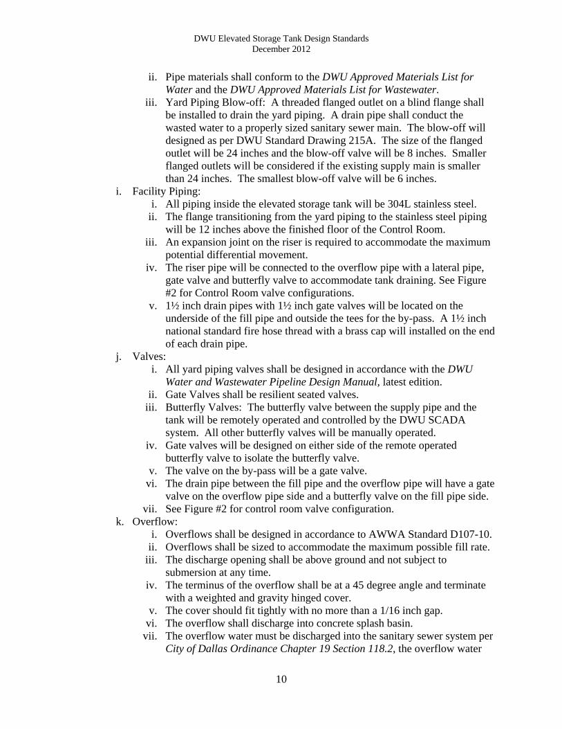
ii. Pipe materials shall conform to the DWU Approved Materials List for Water and the DWU Approved Materials List for Wastewater.
iii. Yard Piping Blow-off: A threaded flanged outlet on a blind flange shall be installed to drain the yard piping. A drain pipe shall conduct the wasted water to a properly sized sanitary sewer main. The blow-off will designed as per DWU Standard Drawing 215A. The size of the flanged outlet will be 24 inches and the blow-off valve will be 8 inches. Smaller flanged outlets will be considered if the existing supply main is smaller than 24 inches. The smallest blow-off valve will be 6 inches.
i. Facility Piping: i. All piping inside the elevated storage tank will be 304L stainless steel.
ii. The flange transitioning from the yard piping to the stainless steel piping will be 12 inches above the finished floor of the Control Room.
iii. An expansion joint on the riser is required to accommodate the maximum potential differential movement.
iv. The riser pipe will be connected to the overflow pipe with a lateral pipe, gate valve and butterfly valve to accommodate tank draining. See Figure #2 for Control Room valve configurations.
v. 1½ inch drain pipes with 1½ inch gate valves will be located on the underside of the fill pipe and outside the tees for the by-pass. A 1½ inch national standard fire hose thread with a brass cap will installed on the end of each drain pipe.
j. Valves: i. All yard piping valves shall be designed in accordance with the DWU
Water and Wastewater Pipeline Design Manual, latest edition. ii. Gate Valves shall be resilient seated valves.
iii. Butterfly Valves: The butterfly valve between the supply pipe and the tank will be remotely operated and controlled by the DWU SCADA system. All other butterfly valves will be manually operated.
iv. Gate valves will be designed on either side of the remote operated butterfly valve to isolate the butterfly valve.
v. The valve on the by-pass will be a gate valve. vi. The drain pipe between the fill pipe and the overflow pipe will have a gate
valve on the overflow pipe side and a butterfly valve on the fill pipe side. vii. See Figure #2 for control room valve configuration.
k. Overflow: i. Overflows shall be designed in accordance to AWWA Standard D107-10.
ii. Overflows shall be sized to accommodate the maximum possible fill rate. iii. The discharge opening shall be above ground and not subject to
submersion at any time. iv. The terminus of the overflow shall be at a 45 degree angle and terminate
with a weighted and gravity hinged cover. v. The cover should fit tightly with no more than a 1/16 inch gap.
vi. The overflow shall discharge into concrete splash basin. vii. The overflow water must be discharged into the sanitary sewer system per
City of Dallas Ordinance Chapter 19 Section 118.2, the overflow water
DWU Elevated Storage Tank Design Standards December 2012
11
must be discharged into the sanitary sewer system. The sanitary sewer system must be sized to accommodate the maximum possible fill rate.
viii. An alarm must be affixed to the overflow that will alert the Water Operations Control Room that the tank is overflowing.
l. Control Room: i. A Control Room that can be secured will be built inside the pedestal of the
tank will be constructed to house the valves and the electronic controls. ii. The Control Room will be located where the yard piping penetrates the
floor of the pedestal and transitions to stainless steel. iii. The ceiling will be made of reinforced concrete and designed to be strong
enough to accommodate hoists used to lift valves and pipe sections inside the Control Room.
iv. The floor will have a 0.5% slope toward the wall and a grate-covered sump that drains into the overflow structure outside.
v. Lockable double hung doors will secure the Control Room. vi. Hooks will be securely anchored into the ceiling of the Control Room over
each butterfly valve to serve as hoist attachments. The hooks will be of adequate strength to support each of the butterfly valves.
vii. A 2-inch flanged outlet with a valve will be installed on the underside of the riser pipe on either side of the butterfly/by-pass valve complex.
viii. If an altitude is not included in the scope of design, but may be required in the future, then accommodations for the future altitude valve must be made.
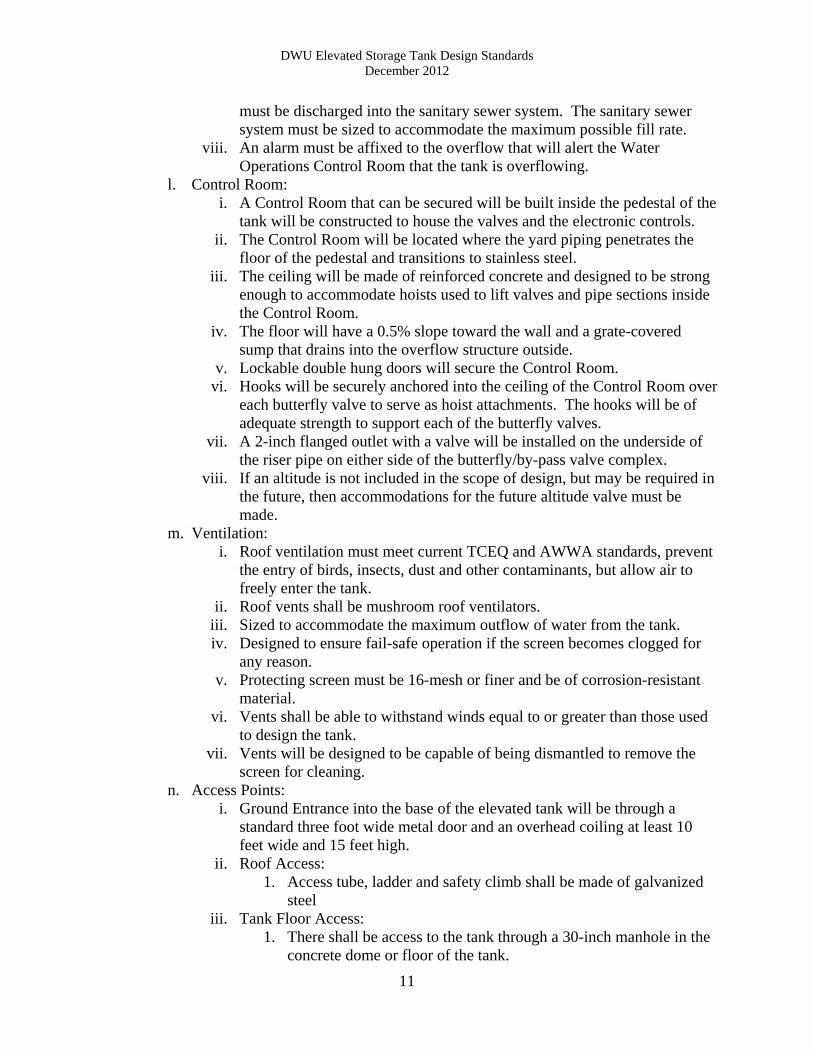
m. Ventilation: i. Roof ventilation must meet current TCEQ and AWWA standards, prevent
the entry of birds, insects, dust and other contaminants, but allow air to freely enter the tank.
ii. Roof vents shall be mushroom roof ventilators. iii. Sized to accommodate the maximum outflow of water from the tank. iv. Designed to ensure fail-safe operation if the screen becomes clogged for
any reason. v. Protecting screen must be 16-mesh or finer and be of corrosion-resistant
material. vi. Vents shall be able to withstand winds equal to or greater than those used
to design the tank. vii. Vents will be designed to be capable of being dismantled to remove the
screen for cleaning. n. Access Points:
i. Ground Entrance into the base of the elevated tank will be through a standard three foot wide metal door and an overhead coiling at least 10 feet wide and 15 feet high.
ii. Roof Access: 1. Access tube, ladder and safety climb shall be made of galvanized
steel iii. Tank Floor Access:
1. There shall be access to the tank through a 30-inch manhole in the concrete dome or floor of the tank.
DWU Elevated Storage Tank Design Standards December 2012
12
2. The manhole assembly shall include a stainless steel hand wheel operator and threaded components.
3. The ladder to the manhole shall be anchored to the catwalk. iv. Tank Roof Access:
1. There shall be access to the tank through the roof of the tank. 2. A steel ladder shall extend from the hatch to the floor of the tank.
v. Ladders, Catwalks, Landings, Painter’s Louver and Railings: 1. All must conform to OSHA standards. 2. Provide a support column ladder, roof access ladder, column
access ladder and tank access ladder. 3. All must be galvanized steel in accordance with ASTM A35 and
ASTM A123 with galvanized steel anchor bolts. 4. Ladder supports shall have a maximum spacing of 10 feet.
vi. Access Tube: 1. Minimum diameter is 54 inches. 2. Access will be from the platform below the tank floor to the tank
roof. 3. The vent will be frost free at the top of the access tube. 4. Provide an 18 inch by 24 inch hinged painter’s vent/manhole at the
base of the access tube for access to the interior of the tank. vii. Access Hatches:
1. All must be at least 30 inches in diameter. 2. Each access must have a raised curb of at least 4 inches. 3. A lockable lid that overlaps the curb by at least 2 inches in a down-
ward direction to prevent rain intrusion. 4. Hatch should seal tight enough to prevent insect intrusion. 5. Provide a hold open arm and a locking mechanism for the hatch. 6. All hatches will have anti-slamming devices.
viii. Ventilation Hatch: 1. Ventilation hatch shall be located adjacent to the access tube. 2. Hatch diameter shall be 24 inches. 3. Hatch will be designed to accommodate painting the ventilation
fan. 4. The cover shall be bolted into place.
ix. Safety Railing: 1. The safety railing will be in accordance with OSHA requirements
and local building codes. 2. Provide a 42 inch high safety railing on the roof around the access
hatches. 3. The railing will be centered on the roof with a 20 foot diameter and
enclose all the access hatches and vents requiring maintenance. 4. The rail will be suitable for mounting antennae and related
equipment. o. Architectural Concrete:
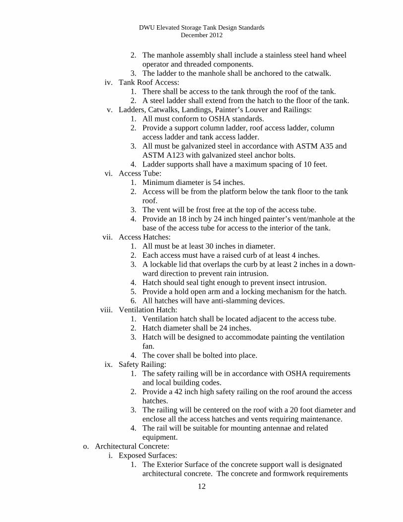
i. Exposed Surfaces: 1. The Exterior Surface of the concrete support wall is designated
architectural concrete. The concrete and formwork requirements
DWU Elevated Storage Tank Design Standards December 2012
13
of this Section shall be strictly enforced to ensure concrete of the highest practicable structural and architectural standard.
2. The Interior Surface does not require architectural form treatment. ii. Concrete Mix Design:
1. The same concrete design mix is used throughout the support wall. 2. The proportion, type and source of cement and aggregates shall not
be changed. 3. Uniform moisture content and placing consistency shall be
maintained. iii. Support Wall Forming:
1. A Jump Form Process shall be used and the segments shall be prefabricated to match the wall curvature.
2. Concrete Pour Height: 6 feet – minimum & 12 feet – maximum. 3. Form panels shall extend the full height of the concrete pour using
only vertical panel joints. 4. The form system shall be designed to lap and be secured to the
previous wall pour. The space between the form and the previous pour shall be sealed to prevent grout leakage.
5. Positive means shall be used to control dimensional tolerances of form system.
6. A uniform pattern of vertical and horizontal rustication pattern shall provide architectural relief to exterior wall surface.
7. Construction and panel joints shall be located in rustications. 8. Rustications shall be proportioned and combined to impart a
symmetrical architectural pattern to the completed structure. 9. Rustication strips shall be sealed to the form face to eliminate the
grout leakage that results in broken corners, color variations and rock pockets. Broken edges and chamfers will not be accepted.
iv. Support Wall Concreting 1. Concrete shall be placed directly between reinforcement layers to
prevent aggregate segregation and form splatter which may cause surface finish variations.
2. Each wall segment of concrete shall be placed continuously to the full form height from a single load. Placement from multiple batches/truckloads is not permitted.
3. Temporary vertical bulkheads may be used to divide the wall pour into segments corresponding to single batches/truckloads of concrete.
4. Any temporary bulkheads shall be located at rustications, braced rigid and tight to maintain vertical alignment under the concrete.
5. Any temporary bulkheads shall be removed after adjacent concrete is placed.
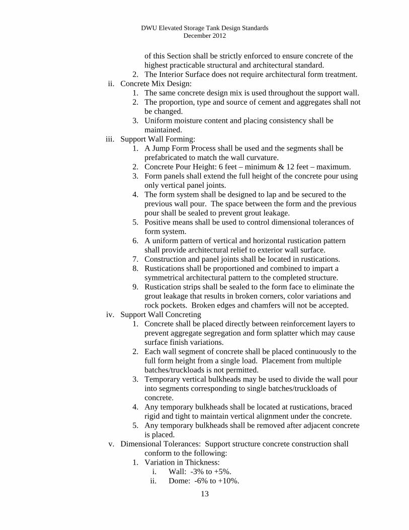
v. Dimensional Tolerances: Support structure concrete construction shall conform to the following:
1. Variation in Thickness: i. Wall: -3% to +5%.
ii. Dome: -6% to +10%.
DWU Elevated Storage Tank Design Standards December 2012
14
iii. Slab floor:-3% to +5 %. 2. Support Wall Variation from Plumb:
i. 1 inch in any 10 feet of height. ii. 2 inches in any 50 feet of height.
iii. 3 inches maximum in total height. 3. Support Wall Diameter Variation:
i. 0.4%; not to exceed 3 inches. 4. Dome Floor Radius Variation: 1% 5. Level Alignment Variation:
i. From Specified Elevation: 1 inch. ii. Form Horizontal Plane: 1/2 inch.
6. Offset between adjacent pieces of formwork: i. Exterior exposed surfaces: 1/8 inch.
ii. Interior exposed surfaces: 1/4 inch. vi. Mock Up Panel:
1. A mock up panel shall be constructed using the proposed form work, concrete and placement methods. The minimum size will be 4 feet wide by 8 feet high. The panel shall be agreed upon by the contractor and owner as the reference standard with which to judge surface quality, appearance and uniformity of texture and color.
2. Concrete with surface defects exceeding limitations specified herein or not meeting the standard represented by the mock-up panel shall be repaired to meet that standard, or removed.
p. Equipment Cranes: i. Motorized Crane:
1. A motorized equipment crane will be provided inside the pedestal of the elevated tank.
2. The capacity of the crane will be determined by the anticipated loads to be moved within the space.
3. The foundation of the crane will be a reinforced concrete pier or pile designed by the engineer and based on the information in section (g).
ii. Manual Crane: 1. A manual jib crane will be located on the catwalk beneath the bowl
of the tank. 2. The crane must be able to hoist up to 500 pound.
q. Architectural Concrete Support Structure: i. Concrete materials and reinforcement shall comply with ACI 318.
ii. The concrete support structure shall be design in accordance with ACI 318.
iii. The expose exterior surface of the concrete support wall will be architectural concrete.
r. Cathodic Protection: Provide for electrical insulation be dissimilar metals. s. Safety Systems:
i. OSHA approved safety climbing systems are required on all interior and exterior ladders.
ii. Ladder cages are unacceptable.
DWU Elevated Storage Tank Design Standards December 2012
15
t. Sampling Port: A sampling port shall be located in the Control Room. u. Chlorine Analyzer:
i. A chlorine analyzer will be located in the Control Room. ii. The chlorine analyzer will sample from the riser pipe.
iii. The sampling discharge will disposed of through tank overflow structure. iv. The results of the chlorine analyzer will be sent to the Water Operations
Control Room via the SCADA system. v. Lighting:
i. Interior lighting must meet current industry foot candle density standards for the specific workspace.
ii. Exterior lighting adequately illuminate the property for security purposes and be located such to limit vandalism potential.
iii. Light switches for the lighting for the catwalks and bowl access must be accessible from the catwalks and not from the ground floor.
w. Lightning Protection: i. Lightning protection shall be designed in accordance with the most current
standards set forth by the: ii. Lightning Protection Institute Code.
iii. National Fire Protection Association Lightning Protection Code, NFPA 780.
iv. Underwriter Laboratories, Inc. Installation Code, UL96A. v. Lightning protection shall be designed, signed and sealed by an Electrical
Engineer registered in the State of Texas. x. FAA Lights: FAA lights will be erected where required. y. Coatings:
i. Coatings shall be NSF approved for potable water. ii. Exterior Color shall be Tnemec – Desert Sands
iii. No text, symbols, advertising or logos of any kind are permitted on the tank or pedestal.
D. SCADA
a. All remote controls and monitoring devices will be controlled by and communicate with the current DWU Water Operations SCADA system and existing operating standards.
b. The SCADA system will, at a minimum, control at least following items: i. Pressure Transmitter.
ii. Chlorine Analyzer. iii. Butterfly Valve. iv. Security Cameras. v. Overflow Alarm.
c. A pressure gauge is required at the tank site. It must be at least 3 inches in diameter and calibrated in at not more than 2 foot intervals.
E. Disinfection
a. Disinfection procedures for the elevated storage tank shall follow AWWA Standard C652-86 Disinfection of Water Storage Facilities.
DWU Elevated Storage Tank Design Standards December 2012
16
b. Disinfection procedures for the yard piping shall follow AWWA Standard C651-99 Disinfection of Water Mains.
F. Quality Assurance
a. Manufacturer’s Qualifications: The work described in this section shall be performed by an elevated tank manufacturer that has a minimum of ten years experience in composite tank design and construction. The manufacturer shall be able to demonstrate the successful, design, construction and completion of at least 5 composite tanks of equal or greater capacity in satisfactory service for at least 5 years.
b. Welder's Qualifications: i. Qualify the specification for each welding procedure in accordance with
the rules in ASME Boiler and Pressure Vessel code. ii. Welders shall be certified by tests in accordance with AWS D1.1 and
D1.3. iii. Welder's certification papers shall be from an independent testing
laboratory. iv. Welder's last qualification shall be within 1 year from the beginning of
construction. v. Engineer, at Engineer's discretion, may accept evidence of previous
qualifications. G. Warranty
a. Warranty shall cover workmanship, materials furnished and repairs. b. Guarantee the work for a period of one (1) year from the date of acceptance of the
work. c. The warranty will cover the repair of defects which appear because of faulty
design, workmanship or material furnished under this contract.
H. Acceptance a. Inspector’s Deficiency List:
i. An initial walk through inspection will be scheduled at substantial completion. The contractor, design engineer, and DWU engineering and operations personnel will attend the inspection. A “punch list” of deficiencies will be created on the initial walk through inspection.
ii. A final walk through inspection will be scheduled when all the deficiencies have been corrected. The contractor, design engineer, and DWU engineering and operations personnel will attend the final inspection.
b. Concrete Tests: i. Concrete tests will be performed by an ACI certified laboratory.
ii. Copies of all concrete tests will be delivered to DWU. c. Weld Inspections:
i. All welds will be inspected by a third party welding inspector to insure that all welds comply with AWS D1.1 and D1.3.
ii. All weld inspection reports will be delivered to DWU.
DWU Elevated Storage Tank Design Standards December 2012
17
d. SCADA Operations: DWU operations staff will determine the best testing procedure for verifying the operability of the new elevated tank.
I. Administrative
a. All design sheet numbers will be provided by DWU. b. All design sheets will be sealed by Professional Engineers registered in the State
of Texas. c. Structural design components will be sealed by a Structural Engineer registered in
the State of Texas. d. Electrical design components will be sealed by an Electrical Engineer registered
in the State of Texas. e. Mechanical components will be sealed by a Mechanical Engineer registered in the
State of Texas. f. All other components of the design will be sealed by a Professional Engineer
registered in the State of Texas. g. The Certificate of Acceptance will be issued jointly by the Water Facilities
Inspectors and the Pumping Division. h. A one year warranty will be placed on any tank constructed in the City of Dallas.
DWU Ground Storage Tank Design Standards December 2012
18
CHAPTER 2
GROUND STORAGE TANK DESIGN GUIDELINES REFERENCES
The following references shall be reviewed in conjunction with this manual: • 30 TAC §290: Public Drinking Water as enforced by Texas Commission on
Environmental Quality (TCEQ), Latest Edition • American Water works Association (AWWA) Standard D110 AWWA Standard for
Wire & Strand Wound, Circular Pre-stressed Concrete Water Tanks, Type III, Latest Edition
• American Water Works Association (AWWA) Standard C652-86 Disinfection of
Water Storage Facilities, Latest Edition. • American Water Works Association (AWWA) Standard C651-99 Disinfection of
Water Mains, Latest Edition. • American Welding Society (AWS) D1.1 and D1.3 Structural Welding Code – Sheet
Steel. • Public Works Construction Standards for North Central Texas by North Central
Texas Council of Governments (NCTCOG), Edition as adopted by DWU • City of Dallas Addendum to the Public Works Construction Standards for North
Central Texas, Latest Edition • Water and Wastewater Procedures and Design Manual by DWU, Latest Edition • Standard Drawings for Water & Wastewater Construction by DWU, Latest Edition • Drafting Standards for Pipeline Projects by DWU, Latest Edition • Dallas City Code: Chapter 49 (Water and Wastewater), City of Dallas, Latest
Edition • City of Dallas Ordinance Chapter 19, Section 118.2, City of Dallas, Latest Edition • Development Design, Procedure and Policy Manual, City of Dallas, Latest Edition • Pavement Cut and Repair Standard Manual, City of Dallas, Latest Edition • Traffic Barricade Manual, City of Dallas, Latest Edition
DWU Ground Storage Tank Design Standards December 2012
19
• Paving Design Manual, City of Dallas, Latest Edition
• Water Capital Infrastructure Assessment & Hydraulic Modeling Report, July 2007
or Latest Update
• 2005 Update Long Range Water Supply Plan, December 31, 2005 or Latest Update
• Water Efficiency Study for City of Dallas, September 3, 2002 or Latest Update
DWU Ground Storage Tank Design Standards December 2012
20
A. Facility Siting a. Properties for ground storage tank facilities shall be owned in fee by the City of
Dallas Water Utilities. i. Facilities built by private developers will be dedicated to the City of
Dallas by warranty deed or plat. ii. Easements or leased property is not acceptable.
b. The ground storage tank facility will be located on a tract of land that has at least one property boundary that is no less than 200 feet and is located on a public municipal right of way that is no less than 60 feet wide. Alleys are not acceptable rights of way.
c. The size of the property shall be sufficiently large so as to accommodate all the current design and construction requirements plus an additional 20% for future expansion and construction staging.
d. The property must be so located to insure a sanitary control radius of at least 150 feet from all septic systems.
e. The outer perimeter of the property shall be no closer than 30 feet from all ground or aerial utility easements.
f. The ground storage tank shall be greater than 500 feet from any municipal or industrial sewage treatment facility or any land which is spray irrigated with treated sewage effluent or sludge.
g. The property must be served by a wastewater main that is sized to accommodate the maximum possible fill rate of the tank.
h. A draft design report must be approved by DWU Engineering Services or Water Facilities and DWU Pumping before moving to the design stage. The design report will include an explanation of the components listed below.
B. Vehicular Access
a. Access to the facility will be via the public right of way. b. The public right of way shall be a concrete paved road. c. The access driveway will be sufficiently wide as to accommodate fire emergency
vehicles. d. Access driveway must abut the base of the tank and any other permanent out
building located on the facility property. e. Parking area will accommodate three vehicles. f. Parking will conform to the current ADA requirements.
C. Security Access and Surveillance
a. Fencing i. All facilities shall be enclosed with an intruder resistant chain link fence
that is (1) a minimum of 6 feet high with three strands of barbed wire or (2) 8 feet high with no barbed wire.
ii. Fencing along the public right of way may be an ornamental fence of steel and/or masonry provided it maintains the same level of intruder resistance as the chain link fence and is approved by the City Engineer.
iii. Vehicular access shall be through a motorized horizontal sliding gate. iv. Pedestrian access will be through a 3 foot wide swinging gate located next
to the sliding vehicular gate.
DWU Ground Storage Tank Design Standards December 2012
21
b. Personnel Access and Surveillance i. Access to the facility will be controlled by the current remote keyless
access and security system. Remote keyless entry shall be for motorized horizontal sliding gates. Pad locks are unacceptable.
ii. Pedestrian access gates may be secured with pad locks. iii. Surveillance cameras will be located per the current security standards.
c. Fire Department access will be through a “knox box”
D. Drainage a. All surface drainage shall comply with City of Dallas Public Works storm
drainage requirements. b. Lot to lot drainage is unacceptable. c. The lot will be graded so as to prevent ponding water. d. Tank overflow drainage shall be directed to the sanitary sewer system per City of
Dallas Ordinance Chapter 19 Section 118.2.
E. Tank Design a. Design Standards:
i. The ground storage tank will be designed in accordance with the requirements set forth by the Texas Commission on Environmental Quality (TCEQ) for such facilities; Chapter 290.43 Water Storage and shall be circular as described below unless otherwise approved by Dallas Water Utilities.
ii. The design of circular tanks will also adhere to design standards set forth in American Water works Association (AWWA) Standard D110 AWWA Standard for Wire & Strand Wound, Circular Pre-stressed Concrete Water Tanks, Type III.
iii. The design of rectangular tanks shall conform to the requirements of ACI 350, Code Requirements for Environmental Engineering Concrete Structures.
iv. All design and construction will be in accordance with the most current version of Public Works Construction Standards – North Texas as published by the North Central Texas Council of Governments (NCTCOG) and the most current version of the City of Dallas Addendum to Public Works Construction Standards – North Texas.
v. Design will follow the latest version of the Water and Wastewater Procedures and Design Manual.
vi. The design will reference the latest edition of the DWU Standard Drawings for Water and Wastewater Construction.
vii. These standards further refine the above noted standards to detail this utility’s specific requirements and preferences.
viii. Tanks must meet all applicable OSHA requirements. b. Tank Location:
i. The tank must be at least 20 feet from all easements. ii. The location must meet the requirements of Section A of this standard.
iii. Tank spacing for multiple tanks facilities must be adequate for anticipated construction and maintenance activities.
DWU Ground Storage Tank Design Standards December 2012
22
iv. Tanks must maintain safe and prudent setbacks from high voltage power easements and facilities. Setbacks shall take into account the permanent structure as well as required work space for future tanks.
c. Tank Sizing: i. The tank shall be sized to meet the storage and fire demands of the service
area. ii. The tank dimensions must be such that the gallons per foot increments are
even numbers easily added, for example 25,000 or 1,000,000 gallons/foot. iii. Tank dimensions must consider and conform to zoning height
requirements. d. Tank Materials:
i. The City of Dallas Water Utility requires that all new and replacement ground storage tanks be built of concrete.
ii. No welded steel, bolted steel or any other kind of material is acceptable. e. Aesthetics: The façade of the facility will be so designed to be pleasing to the
general public. Architectural elements, color and landscaping will be used make an attractive structure that will not draw negative attention from the public.
f. Water Quality: i. The tank must be designed to minimize stratification and have adequate
circulation and baffling to prevent “dead spots” within the water column and short circuiting across the tank.
ii. The designer will model the behavior of the water in the tank using a Computational Fluid Dynamic (CFD) model and system behavior data, including, but not limited to, diurnal cycles and chlorine levels provided by DWU Operations and demonstrate to the Department how the water how stratification and short circuiting will be minimized.
g. Inflow Structure: i. The finished floor evaluation of tank must be located so to keep the pumps
primed and minimize suction losses. ii. The maximum fill level of the tank must be an elevation that the hydraulic
grade line of the supply main can reach. iii. Water Operations will determine if the tank will fill from the top or the
bottom. h. Geotechnical:
i. A complete geotechnical evaluation must be completed with recommendations for the foundation of the tank, any other out buildings and all paving.
ii. The geotechnical evaluation must meet the design needs of the tank manufacturer.
iii. The report must be sealed by a Registered Professional Geotechnical Engineer Registered in the State of Texas.
i. Yard Piping: i. Yard piping shall be designed in accordance with the Water and
Wastewater Procedures and Design Manual, latest edition. ii. Pipe materials shall conform to the DWU Approved Materials List for
Water and the DWU Approved Materials List for Wastewater.
DWU Ground Storage Tank Design Standards December 2012
23
j. Valves: i. All yard piping valves shall be designed in accordance with the DWU
Water and Wastewater Procedures and Design Manual, latest edition. ii. Yard piping must be configured to meet all the operational needs of the
facility. iii. Gate Valves shall be resilient seated valves.
k. Overflow Structure: i. Overflows shall be designed in accordance to AWWA Standard D110.
ii. Overflows shall be sized to accommodate the maximum possible fill rate. iii. The discharge opening shall be above ground and not subject to
submersion at any time. iv. The terminus of the overflow shall be at a 45 degree angle and terminate
with a weighted and gravity hinged cover. v. The overflow shall discharge into concrete splash basin.
vi. Per City of Dallas Ordinance Chapter 19 Section 118.2, the overflow water must be discharged into the sanitary sewer system. The sanitary sewer system must be sized to accommodate the maximum possible fill rate.
vii. An alarm must be affixed to the overflow that will alert the Water Operations Control Room in the event of an overflow.
l. Ventilation: i. Roof ventilation meet current TCEQ and AWWA standards, prevent the
entry of birds, insects, dust and other contaminants allow air to freely enter the tank.
ii. Roof vents shall be mushroom roof ventilators. iii. Sized to accommodate the maximum outflow of water from the tank. iv. Protecting screen must be 16-mesh or finer and be of 316 stainless steel,
fiberglass or other corrosion-resistant materials approved by DWU. v. Vents shall be able to withstand winds equal to or greater than those used
to design the tank. m. Access:
i. Ground access into the base of the tank, if required, to be through a wall man way shall be a minimum of 24 inches in diameter.
ii. Roof Access: 1. There shall be access to the tank through the roof of the tank. 2. A grade 403 stainless steel ladder shall extend from the hatch to
the floor of the tank. 3. A landing around the Roof Access will be large enough to
accommodate the currently required number of confined space personnel.
iii. Ladders, Catwalks, Landings and Railings: 1. All must conform to OSHA standards. 2. All must be 304 stainless steel and have stainless steel anchor
bolts. iv. Access Hatches:
1. All must be at least 30 inches in diameter. 2. Each access must have a raised curb of at least 4 inches.
DWU Ground Storage Tank Design Standards December 2012
24
3. A lockable lid that overlaps the curb by at least 2 inches in a down-ward direction to prevent rain intrusion.
4. Hatch should seal tight enough to prevent insect intrusion. n. Cathodic Protection: Provide for electrical insulation be dissimilar metals. o. Safety Systems:
i. OSHA approved safety climbing systems are required on all interior and exterior ladders.
ii. Ladder cages are unacceptable. p. Lighting: Exterior lighting adequately illuminate the property for security
purposes and be located such to limit vandalism potential. q. Lightning Protection:
i. Lightning Protection Institute Code. ii. National Fire Protection Association Lightning Protection Code,
NFPA 780. iii. Underwriter Laboratories, Inc. Installation Code, UL96A. iv. Lightning protection shall be designed, signed and sealed by an Electrical
Engineer registered in the State of Texas. r. Coatings:
i. Coatings shall be NSF approved for potable water. ii. Exterior Color shall be Tnemec – Desert Sands
iii. No text, symbols, advertising or logos of any kind are permitted on the tank.
F. SCADA
a. All remote controls and monitoring devices will be controlled by and communicate with the Water Operations SCADA system.
b. The SCADA system will, at a minimum, control at least following items: i. Water Level Indicator.
ii. Security Cameras. iii. Overflow Alarm.
c. A pressure gauge is required at the tank site. It must be at least 3 inches in diameter and calibrated in at not more than 2 foot intervals.
G. Disinfection
a. Disinfection procedures for the elevated storage tank shall follow AWWA Standard C652 Disinfection of Water Storage Facilities.
b. Disinfection procedures for the yard piping shall follow AWWA Standard C651 Disinfection of Water Mains.
H. Quality Assurance
Manufacturer’s Qualifications: The work described in this section shall be performed by an elevated tank manufacturer that has a minimum of ten years experience in composite tank design and construction. The manufacturer shall be able to demonstrate the successful, design, construction and completion of at least 5 composite tanks of equal or greater capacity in satisfactory service for at least 5 years.
DWU Ground Storage Tank Design Standards December 2012
25
I. Warranty a. Warranty shall cover workmanship, materials furnished and repairs. b. Guarantee the work for a period of one (1) year from the date of acceptance of the
work. c. The warranty will cover the repair of defects which appear because of faulty
design, workmanship or material furnished under this contract.
J. Acceptance a. Inspector’s Deficiency List:
i. An initial walk through inspection will be scheduled at substantial completion. The contractor, design engineer, and DWU engineering and operations personnel will attend the inspection. A “punch list” of deficiencies will be created on the initial walk through inspection.
ii. A final walk through inspection will be scheduled when all the deficiencies have been corrected. The contractor, design engineer, and DWU engineering and operations personnel will attend the final inspection.
b. Concrete Tests: i. Concrete tests will be performed by an ACI certified laboratory.
ii. Copies of all concrete tests will be delivered to DWU. c. Weld Inspections:
i. All welds will be inspected by a third party welding inspector to insure that all welds comply with AWS D1.1 and D1.3.
ii. All weld inspection reports will be delivered to DWU. d. SCADA Operations: DWU operations staff will determine the best testing
procedure for verifying the operability of the new tank.
K. Administrative a. All design sheet numbers will be provided by DWU. b. All design sheets will be sealed by Professional Engineers registered in the State
of Texas. c. Structural design components will be sealed by a Structural Engineer registered in
the State of Texas. d. Electrical design components will be sealed by an Electrical Engineer registered
in the State of Texas. e. Mechanical components will be sealed by a Mechanical Engineer registered in the
State of Texas. f. All other components of the design will be sealed by a Professional Engineer
registered in the State of Texas. g. The Certificate of Acceptance will be issued jointly by the Water Facilities
Inspectors and the Pumping Division. h. A one year warranty will be placed on any tank constructed in the City of Dallas.
DWU Elevated Storage Tank and Ground Storage Tank Design Standards December 2012
APPENDIX
Figure 1 ..............................................Hypothetical Elevated Storage Tank Site Configuration Figure 2 ..............................................Elevated Storage Tank Valve Configuration
Supply Pipe, By-Pass, Fill Pipe & Drain Pipe