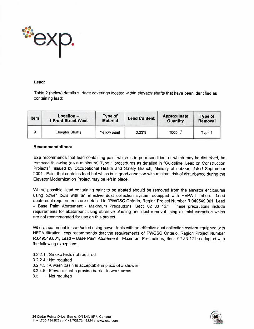
elevator modernization project
TRANSCRIPT

Public Works and Government Services Canada Architectural and Engineering Services Ontario Region
Toronto, Ontario
1 Front Street West
ELEVATOR MODERNIZATION
PROJECT
PWGSC Project No. R.049549.001
SPECIFICATIONS
Issued for Tender 2013-08-29


PWGSC Ontario SPECIFICATION Section 00 00 00
Region Project TITLE SHEET Page 1
Number R.049549.001 2013-08-29
Project Title Elevator Modernization Project
Project Number R.049549.001
Project Date 2013-08-29


PWGSC Ontario List of Contents Section 00 01 11
Region Project Page 1
Number R.049549.001 2013-08-29
Section Title Pages
Division 01 - General Requirements
00 00 00 TITLE SHEET 1
00 01 07 PROFESSIONAL SEALS PAGE 1
00 01 11 LIST OF CONTENTS 2
01 11 00 SUMMARY OF WORK 2
01 14 00 WORK RESTRICTIONS 4
01 21 00 ALLOWANCES 2
01 29 83 PAYMENT PROCEDURES FOR TESTING LABORATORY
SERVICES 2
01 31 16 PROJECT MANAGEMENT AND COORDINATION 5
01 31 19 PROJECT MEETINGS 3
01 32 16 CONSTRUCTION PROGRESS SCHEDULE - BAR (GANTT)
CHART 3
01 33 00 SUBMITTAL PROCEDURES 6
01 35 29 HEALTH AND SAFETY REQUIREMENTS 6
01 35 35 FIRE SAFETY REQUIREMENTS 5
01 41 00 REGULATORY REQUIREMENTS 2
01 45 00 QUALITY CONTROL 4
01 51 00 TEMPORARY UTILITIES 3
01 52 00 CONSTRUCTION FACILITIES 4
01 56 00 TEMPORARY BARRIERS AND ENCLOSURES 3
01 61 00 COMMON PRODUCT REQUIREMENTS 6
01 71 00 EXAMINATION AND PREPARATION 2
01 73 00 EXECUTION 3
01 74 11 CLEANING 3
01 74 20 CONSTRUCTION/DEMOLITION WASTE MANAGEMENT AND
DISPOSAL 2
01 77 00 CLOSEOUT PROCEDURES 2
01 78 00 CLOSEOUT SUBMITTALS 7
01 79 00 DEMONSTRATION AND TRAINING 2
01 91 13 GENERAL COMMISSIONING (CX) REQUIREMENTS 11
01 91 31 COMMISSIONING (CX) PLAN 12
01 91 33 COMMISSIONING FORMS 3
01 91 41 COMMISSIONING TRAINING 4
01 91 51 BUILDING MANAGEMENT MANUAL (BMM) 5
Division 02 – Existing Conditions
02 82 00.01 ASBESTOS ABATEMENT – MINIMUM PRECAUTIONS 9
02 83 12 LEAD – BASE PAINT ABATEMENT – MAXIMUM PRECAUTIONS 13
Division 07 - Thermal and Moisture Protection
07 81 00 APPLIED FIREPROOFING 6
07 84 00 FIRE STOPPING 6
07 90 00 JOINT SEALING 4
Division 09 - Finishes
09 22 14 FURRING AND LATHING 4
09 23 00 GYPSUM PLASTERING 6
09 91 23.01 INTERIOR RE-PAINTING 15
PWGSC Ontario List of Contents Section 00 01 11
Region Project Page 2
Number R.049549.001 2013-08-29
Division 14 - Conveying Equipment
14 05 00 ELEVATOR GENERAL PROVISIONS 41
14 21 13 ELECTRIC TRACTION FREIGHT ELEVATOR 15
14 21 23 ELECTRIC TRACTION PASSENGER ELEVATORS 19
-------- ANNEX A – SPECIFICATIONS FOR ELEVATING DEVICES
MAINTENANCE 9
Division 23 - Heating, Ventilating and Air-Conditioning (HVAC)
23 05 00 COMMON WORK RESULTS - MECHANICAL 5
23 05 05 INSTALLATION OF PIPEWORK 4
23 05 29 HANGERS AND SUPPORTS FOR HVAC PIPING AND EQUIPMENT 6
23 05 93 TESTING, ADJUSTING AND BALANCING FOR HVAC 5
23 07 15 THERMAL INSULATION FOR PIPING 6
23 23 00 COPPER TUBING AND FITTINGS REFRIGERANT 4
23 81 11 DUCTLESS SPLIT SYSTEM A/C UNITS 9
23 82 39.01 UNIT HEATERS – ELECTRIC 3
Division 26 - Electrical
26 05 00 COMMON WORK RESULTS - FOR ELECTRICAL 5
26 05 20 WIRE AND BOX CONNECTORS (0-1000 V) 1
26 05 21 WIRES AND CABLES (0-1000 V) 1
26 05 22 CONNECTORS AND TERMINATIONS 1
26 05 28 GROUNDING - SECONDARY 2
26 05 29 HANGERS AND SUPPORTS FOR ELECTRICAL SYSTEMS 2
26 05 31 SPLITTERS, JUNCTION, PULL BOXES AND CABINETS 1
26 05 34 CONDUITS, CONDUIT FASTENINGS AND CONDUIT FITTINGS 3
26 12 16.01 DRY TYPE TRANSFORMERS UP TO 600 V PRIMARY 3
26 24 16.01 PANELBOARDS BREAKER TYPE 4
26 27 26 WIRING DEVICES 2
26 28 13.01 FUSES - LOW VOLTAGE 1
26 28 16.02 MOULDED CASE CIRCUIT BREAKERS 2
26 28 20 GROUND FAULT CIRCUIT INTERRUPTERS – CLASS “A” 3
26 28 23 DISCONNECT SWITCHES - FUSED AND NON-FUSED 1
26 50 00 LIGHTING 3
Division 27 - Communications
27 05 13 COMMUNICATIONS SERVICES 1
27 51 23 INTERCOMMUNICATIONS AND PROGRAM SYSTEMS 1
Division 28 - Electronic Safety and Security
28 31 00 FIRE DETECTION AND ALARM 5
-------- “Elevator Modernization Project – Hazardous
Materials” dated July 29, 2013, prepared by
exp Services Inc. 6
-------- “Limited Asbestos & Designated Substances Survey”
dated 29.06.12, prepared by exp Services Inc. 42

PWGSC Ontario SUMMARY OF WORK Section 01 11 00
Region Project Page 1
Number R.049549.001 2013-08-29
PART 1 - GENERAL
1.1 PRECEDENCE
.1 For Federal Government projects, Division 01 Sections
take precedence over technical specification sections
in other Divisions of this Project Manual.
1.2 WORK COVERED BY
CONTRACT DOCUMENTS
.1 Work of this Contract comprises general renovation of
elevators and elevator machinery, located at 1 Front
St. Toronto, Ontario; and further identified as
"Elevator Modernization Project".
1.3 CONTRACT METHOD
.1 Construct Work under lump sum contract.
.2 Relations and responsibilities between Contractor and
subcontractors are as defined in Conditions of
Contract.
1.4 COST BREAKDOWN
.1 Within 5 days of notification of acceptance of bid
furnish a cost breakdown by Section aggregating
contract amount.
.2 Within 48 hours of acceptance of bid submit a list of
subcontractors.
1.5 WORK SEQUENCE
.1 Construct Work in stages to accommodate Owner's
continued use of premises during construction.
.2 Coordinate Progress Schedule and coordinate with Owner
Occupancy during construction.
.3 Construct Work in stages to provide for continuous
public usage. Do not close off public usage of
facilities until use of one stage of Work will provide
alternate usage.
.4 For the sequence of work refer to Section 14 05 00.
.5 Maintain fire access/control.

PWGSC Ontario SUMMARY OF WORK Section 01 11 00
Region Project Page 2
Number R.049549.001 2013-08-29
1.6 CONTRACTOR USE
OF PREMISES
.1 Contractor shall limit use of premises for Work, for
storage, and for access, to allow;
.1 Owner occupancy.
.2 Work by other contractors.
.3 Public usage.
.2 Coordinate use of premises under direction of
Departmental Representative.
.3 Obtain and pay for use of additional storage or work
areas needed for operations under this Contract.
.4 Obtain and pay for security services required by the
Contractor.
1.7 OWNER OCCUPANCY
.1 Owner will occupy premises during entire construction
period for execution of normal operations.
.2 Cooperate with Owner in scheduling operations to
minimize conflict and to facilitate Owner usage.
1.8 ALTERATIONS TO
EXISTING BUILDING
.1 Remove and recycle, compost, anaerobic digest, for
reuse, or dispose of demolition materials.
PART 2 - PRODUCTS
2.1 NOT USED
.1 Not used.
PART 3 - EXECUTION
3.1 NOT USED .1 Not used.
END OF SECTION

PWGSC Ontario WORK RESTRICTIONS Section 01 14 00
Region Project Page 1
Number R.049549.001 2013-08-29
PART 1 - GENERAL
1.1 ACCESS AND
EGRESS
.1 Design, construct and maintain temporary "access to"
and "egress from" work areas, including stairs,
runways, ramps or ladders and scaffolding, independent
of finished surfaces and in accordance with relevant
municipal, provincial and other regulations.
1.2 USE OF SITE AND
FACILITIES
.1 Execute work with least possible interference or
disturbance to normal use of premises. Make
arrangements with Departmental Representative to
facilitate work as stated.
.2 Maintain existing services to building and provide for
personnel and vehicle access.
.3 Where security is reduced by work provide temporary
means to maintain security.
.4 Departmental Representative will assign sanitary
facilities for use by Contractor's personnel. Keep
facilities clean.
.5 Use only elevators, existing in building for moving
workers and material.
.1 Protect walls of passenger elevators, to
approval of Departmental Representative prior to use.
.2 Accept liability for damage, safety of equipment
and overloading of existing equipment.
.6 Closures: protect work temporarily until permanent
enclosures are completed.
1.3 PARKING
.1 Parking is not available on site.
.2 Should the Contractor require parking after normal
working hours (07:00 - 18:00) the Contractor will be
required to pay parking fees.
1.4 ALTERATIONS,
ADDITIONS OR
REPAIRS TO EXISTING
BUILDING
.1 Execute work with least possible interference or
disturbance to building operations, occupants, public
and normal use of premises. Arrange with Departmental
Representative to facilitate execution of work.
.2 Execute work so as not more than two elevators are down
at the same time.

PWGSC Ontario WORK RESTRICTIONS Section 01 14 00
Region Project Page 2
Number R.049549.001 2013-08-29
1.5 EXISTING
SERVICES
.1 Notify, Departmental Representative utility companies
of intended interruption of services and obtain
required permission.
.2 Where Work involves breaking into or connecting to
existing services, give Departmental Representative
7 days of notice for necessary interruption of
mechanical or electrical service throughout course of
work. Keep duration of interruptions minimum. Carry
out interruptions after normal working hours of
occupants, preferably on weekends.
.3 Provide for personnel pedestrian and vehicular
traffic.
.4 Construct barriers in accordance with Section
01 56 00.
1.6 SPECIAL
REQUIREMENTS
.1 Regular work hours are Monday to Friday 07:00 hours
to 18:00 hours.
.2 Work will only be permitted during weekends and
statutory holidays with the permission of the
Departmental Representative. A minimum of 3 days
advance notice will be required to obtain the required
permission. In case of emergencies or other special
circumstances, this advance notice may be waived by
the Departmental Representative.
.3 Paint public or Departmental Representative occupied
areas Monday to Friday from 18:00 to 07:00 hours only
and on Saturdays, Sundays, and statutory holidays.
.4 Carry out noise generating Work Monday to Friday from
18:00 to 07:00 hours and on Saturdays, Sundays, and
statutory holidays.
.5 Submit schedule in accordance with Section 01 32 16
- Construction Progress Schedule - Bar (GANTT) Chart.
.6 Ensure Contractor's personnel employed on site become
familiar with and obey regulations including safety,
fire, traffic and security regulations.
.7 Keep within limits of work and avenues of ingress and
egress.
.8 Deliver materials outside of peak traffic hours 17:00
to 07:00 and 13:00 to 15:00 unless otherwise approved
by Departmental Representative.
.9 Prior to cutting or drilling horizontal or vertical
surfaces including concrete, concrete block or other
structural substrate, determine location of

PWGSC Ontario WORK RESTRICTIONS Section 01 14 00
Region Project Page 3
Number R.049549.001 2013-08-29
reinforcing, service lines, pipes, conduits or other
items by x-ray, ground penetrating radar or other
appropriate method. Submit findings to Departmental
Representative prior to cutting or drilling.
1.7 SECURITY
.1 Where security has been reduced by Work of Contract,
provide temporary means to maintain security.
.2 Security clearances:
.1 Personnel employed on this project will be
subject to security check. Obtain clearance, as
instructed, for each individual who will require to
enter premises.
.2 Obtain requisite clearance, as instructed, for
each individual required to enter premises.
.3 Personnel will be checked daily at start of work
shift and provided with pass which must be worn at all
times. Pass must be returned at end of work shift and
personnel checked out.
.3 Security escort:
.1 Personnel employed on this project must be
escorted when executing work in non-public areas during
normal working hours. Personnel must be escorted in
all areas after normal working hours.
.2 Submit an escort request to Departmental
Representative at least 14 days before service is
needed. For requests submitted within time noted above,
costs of security escort will be paid for by
Departmental Representative. Cost incurred by late
request will be Contractor's responsibility.
.3 Any escort request may be cancelled free of
charge if notification of cancellation is given at
least 24 hours before scheduled time of escort. Cost
incurred by late request will be Contractor's
responsibility.
.4 Calculation of costs will be based on average
hourly rate of security officer for minimum of 8 hours
per day for late service request and of 8 hours for
late cancellations.
1.8 BUILDING
SMOKING ENVIRONMENT
.1 Comply with smoking restrictions. Smoking is not
permitted.

PWGSC Ontario WORK RESTRICTIONS Section 01 14 00
Region Project Page 4
Number R.049549.001 2013-08-29
PART 2 - PRODUCTS
2.1 NOT USED
.1 Not Used.
PART 3 - EXECUTION
3.1 NOT USED
.1 Not Used.
END OF SECTION

PWGSC Ontario PAYMENT PROCEDURES FOR Section 01 29 83
Region Project TESTING LABORATORY SERVICES Page 1
Number R.049549.001 2013-08-29
PART 1 - GENERAL
1.1 APPOINTMENT AND
PAYMENT
.1 Departmental Representative will appoint and pay for
services of testing laboratory except follows:
.1 Inspection and testing required by laws,
ordinances, rules, regulations or orders of public
authorities.
.2 Inspection and testing performed exclusively for
Contractor's convenience.
.3 Testing, adjustment and balancing of conveying
systems, mechanical and electrical equipment and
systems.
.4 Mill tests and certificates of compliance.
.5 Tests specified to be carried out by Contractor
under supervision of Departmental Representative.
.2 Where tests or inspections by designated testing
laboratory reveal Work not in accordance with contract
requirements, pay costs for additional tests or
inspections as required by Departmental Representative
to verify acceptability of corrected work.
1.2 CONTRACTOR'S
RESPONSIBILITIES
.1 Provide labour, equipment and facilities to: .1 Provide access to Work for inspection and
testing.
.2 Facilitate inspections and tests.
.3 Make good Work disturbed by inspection and test.
.4 Provide storage on site for laboratory's
exclusive use to store equipment and cure test samples.
.2 Notify Departmental Representative 48 hours minimum
sufficiently in advance of operations to allow for
assignment of laboratory personnel and scheduling of
test.
.3 Where materials are specified to be tested, deliver
representative samples in required quantity to testing
laboratory.
.4 Pay costs for uncovering and making good Work that is
covered before required inspection or testing is
completed and approved by Departmental Representative.

PWGSC Ontario PAYMENT PROCEDURES FOR Section 01 29 83
Region Project TESTING LABORATORY SERVICES Page 2
Number R.049549.001 2013-08-29
PART 2 - PRODUCTS
2.1 NOT USED
.1 Not Used.
PART 3 - EXECUTION
3.1 NOT USED
.1 Not Used.
END OF SECTION

PWGSC Ontario PROJECT MANAGEMENT AND Section 01 31 16
Region Project COORDINATION Page 1
Number R.049549.001 2013-08-29
PART 1 - GENERAL
1.1 RELATED
SECTIONS
.1 Section 01 11 00 - Summary of Work.
.2 Section 01 91 13 - General Commissioning (CX)
Requirements.
1.2 DESCRIPTION
.1 Coordination of progress schedules, submittals, use
of site, temporary utilities, construction facilities,
and construction Work, with progress of Work of other
contractors, under instructions of Departmental
Representative.
1.3 PROJECT
MEETINGS
.1 Schedule and administer weekly project meetings
throughout progress of Work as determined by
Departmental Representative.
.2 Prepare agenda for meetings.
.3 Distribute written notice of each meeting four days
in advance of meeting date to Departmental
Representative.
.4 Provide physical space and make arrangements for
meetings.
.5 Preside at meetings.
.6 Record minutes. Include significant proceedings and
decisions. Identify action by parties.
.7 Reproduce and distribute copies of minutes within three
days after each meeting and transmit to meeting
participants, affected parties not in attendance,
Departmental Representative.
1.4 CONSTRUCTION
ORGANIZATION AND
START-UP
.1 Within 10 days after award of Contract, request a
meeting of parties in contract to discuss and resolve
administrative procedures and responsibilities.
.2 Senior representatives of Departmental
Representative, Contractor, major Subcontractors,
field inspectors and supervisors will be in attendance.

PWGSC Ontario PROJECT MANAGEMENT AND Section 01 31 16
Region Project COORDINATION Page 2
Number R.049549.001 2013-08-29
.3 Establish time and location of meeting and notify
parties concerned minimum 5 days before meeting.
.4 Agenda to include following:
.1 Appointment of official representative of
participants in Work.
.2 Schedule of Work, progress scheduling in
accordance with Section 01 32 16.
.3 Schedule of submission of shop drawings,
samples, colour chips in accordance with Section
01 33 00.
.4 Requirements for temporary facilities, site
sign, offices, storage sheds, utilities, fences in
accordance with Section 01 51 00.
.5 Delivery schedule of specified equipment in
accordance with Section 01 32 16.
.6 Site security in accordance with Section
01 52 00.
.7 Proposed changes, change orders, procedures,
approvals required, mark-up percentages permitted,
time extensions, overtime, and administrative
requirements (GC).
.8 Departmental Representative provided Products.
.9 Record drawings in accordance with Section
01 78 00.
.10 Maintenance in accordance with Section 01 78 00.
.11 Commissioning in accordance with Section
01 91 13.
.12 Take-over procedures, acceptance, and
warranties in accordance with Section 01 77 00 and
01 78 00.
.13 Monthly progress claims, administrative
procedures, photographs, and holdbacks (GC).
.14 Appointment of inspection and testing agencies
or firms in accordance with Section 01 45 00.
.15 Insurances and transcript of policies (GC).
.6 Comply with Departmental Representative's allocation
of mobilization areas of site; for field offices and
sheds, for access, traffic, and parking facilities.
.7 During construction coordinate use of site and
facilities through Departmental Representative's
procedures for intra-project communications:
Submittals, reports and records, schedules,
coordination of drawings, recommendations, and
resolution of ambiguities and conflicts.
.8 Comply with instructions of Departmental
Representative for use of temporary utilities and
construction facilities.
.9 Coordinate field engineering and layout work with
Departmental Representative.

PWGSC Ontario PROJECT MANAGEMENT AND Section 01 31 16
Region Project COORDINATION Page 3
Number R.049549.001 2013-08-29
1.5 ON-SITE
DOCUMENTS
.1 Maintain at job site, one copy each of the following:
.1 Contract drawings.
.2 Specifications.
.3 Amendments.
.4 Reviewed shop drawings.
.5 Change orders.
.6 Other modifications to Contract.
.7 Field test reports.
.8 Copy of approved Work schedule.
.9 Manufacturers' installation and application
instructions.
.10 Labour conditions and wage schedules.
.11 Material Safety Data Sheets.
.12 Labour and Material Bonds.
.13 All applicable Municipal Permits.
1.6 SCHEDULES
.1 Submit preliminary construction progress schedule in
accordance with Section 01 32 16 and Commissioning
Schedule in accordance with Section 01 91 13 to
Departmental Representative coordinated with
Departmental Representative's project schedule.
.2 After review, revise and resubmit schedule to comply
with revised project schedule.
.3 During progress of Work revise and resubmit as directed
by Departmental Representative.
1.7 CONSTRUCTION
PROGRESS MEETINGS
.1 During course of Work and 2 weeks prior to project
completion, schedule progress meetings bi-weekly.
.2 Schedule separate commissioning meetings in accordance
with Section 01 91 13.
.3 Contractor, major subcontractors involved in Work and
Departmental Representative are to be in attendance.
.4 Notify parties minimum 5 days prior to meetings.
.5 Record minutes of meetings and circulate to attending
parties and affected parties not in attendance within
3 days after meeting.
.6 Agenda to include following:
.1 Review, approval of minutes of previous meeting.
.2 Review of Work progress since previous meeting.
.3 Field observations, problems, conflicts.
.4 Problems which impede construction schedule.
.5 Review of off-site fabrication delivery
schedules.
.6 Corrective measures and procedures to regain
projected schedule.

PWGSC Ontario PROJECT MANAGEMENT AND Section 01 31 16
Region Project COORDINATION Page 4
Number R.049549.001 2013-08-29
.7 Revision to construction schedule.
.8 Progress schedule, during succeeding work
period.
.9 Review submittal schedules: expedite as
required.
.10 Maintenance of quality standards.
.11 Review proposed changes for effect on
construction schedule and on completion date.
.12 Other business.
1.8 SUBMITTALS
.1 Make submittal to Departmental Representative for
review.
.2 Submit preliminary shop drawings, product data and
samples in accordance with Section 01 33 00 and
01 91 13 for review for compliance with Contract
Documents; for field dimensions and clearances, for
relation to available space, and for relation to Work
of other contracts. After review, revise and resubmit
for transmittal to Departmental Representative.
.3 Submit requests for payment for review, and for
transmittal to Departmental Representative.
.4 Submit requests for interpretation of Contract
Documents, and obtain instructions through
Departmental Representative.
.5 Process substitutions through Departmental
Representative.
.6 Process change orders through Departmental
Representative.
.7 Deliver closeout submittals for review and preliminary
inspections, for transmittal to Departmental
Representative.
1.9 COORDINATION
DRAWINGS
.1 Provide information required by Departmental
Representative for preparation of coordination
drawings.
.2 Review and approve revised drawings for submittal to
Departmental Representative.
1.10 CLOSEOUT
PROCEDURES
.1 Notify Departmental Representative when Work is
considered ready for Substantial Performance.
.2 Accompany Departmental Representative on preliminary

PWGSC Ontario PROJECT MANAGEMENT AND Section 01 31 16
Region Project COORDINATION Page 5
Number R.049549.001 2013-08-29
inspection to determine items listed for completion
or correction.
.3 Comply with Departmental Representative's
instructions for correction of items of Work listed
in executed certificate of Substantial Performance and
for access to occupied areas.
.4 Notify Departmental Representative of instructions for
completion of items of Work determined in Departmental
Representative's final inspection.
PART 2 - PRODUCTS
2.1 NOT USED
.1 Not Used.
PART 3 - EXECUTION
3.1 NOT USED
.1 Not Used.
END OF SECTION


PWGSC Ontario PROJECT MEETINGS Section 01 31 19
Region Project Page 1
Number R.049549.001 2013-08-29
PART 1 - GENERAL
1.1 ADMINISTRATIVE
.1 Schedule and administer project meetings throughout
the progress of the work at the call of Departmental
Representative.
.2 Prepare agenda for meetings.
.3 Distribute written notice of each meeting 5 days in
advance of meeting date to Departmental
Representative.
.4 Provide physical space and make arrangements for
meetings.
.5 Preside at meetings.
.6 Record the meeting minutes. Include significant
proceedings and decisions. Identify actions by
parties.
.7 Reproduce and distribute copies of minutes within three
days after meetings and transmit to Departmental
Representative, meeting participants and affected
parties not in attendance.
.8 Representative of Contractor, Subcontractor and
suppliers attending meetings will be qualified and
authorized to act on behalf of party each represents.
1.2 PRECONSTRUCTION
MEETING
.1 Within 10 days after award of Contract, request meeting
of parties in contract to discuss and resolve
administrative procedures and to discuss and
responsibilities.
.2 Departmental Representative, Contractor, major
Subcontractors, field inspectors and supervisors will
be in attendance.
.3 Establish time and location of meeting and notify
parties concerned minimum 5 days before meeting.
.4 Incorporate mutually agreed variations to Contract
Documents into Agreement, prior to signing.
.5 Agenda to include:
.1 Appointment of official representative of
participants in the Work.
.2 Schedule of Work: in accordance with Section
PWGSC Ontario PROJECT MEETINGS Section 01 31 19
Region Project Page 2
Number R.049549.001 2013-08-29
01 32 16.
.3 Schedule of submission of shop drawings,
samples, mock-ups, colour chips. Submit submittals in
accordance with Section 01 33 00.
.4 Requirements for temporary facilities, site
sign, offices, storage sheds, utilities, fences in
accordance with Section 01 52 00.
.6 Site security in accordance with Section
01 56 00.
.7 Health and safety in accordance with Section
01 35 29.
.7 Proposed changes, change orders, procedures,
approvals required, mark-up percentages permitted,
time extensions, overtime, administrative
requirements.
.8 Record drawings and specifications in accordance
with Section 01 33 00.
.9 Maintenance manuals in accordance with Section
01 78 00.
.10 Take-over procedures, acceptance, warranties in
accordance with Section 01 78 00.
.11 Monthly progress claims, administrative
procedures, photographs, hold backs.
.12 Appointment of inspection and testing agencies
or firms.
.13 Insurances, transcript of policies.
1.3 PROGRESS
MEETINGS
.1 During course of Work and 2 weeks prior to project
completion, schedule progress meetings every two
weeks.
.2 Contractor, major Subcontractors involved in Work and
Departmental Representative are to be in attendance.
.3 Notify parties minimum 5 days prior to meetings.
.4 Record minutes of meetings and circulate to attending
parties and affected parties not in attendance within
3 days after meeting.
.5 Agenda to include the following:
.1 Review, approval of minutes of previous meeting.
.2 Review of Work progress since previous meeting.
.3 Field observations, problems, conflicts.
.4 Problems which impede construction schedule.
.5 Review of off-site fabrication delivery
schedules.
.6 Corrective measures and procedures to regain
projected schedule.
.7 Revision to construction schedule.
.8 Progress schedule, during succeeding work
period.
.9 Review submittal schedules: expedite as
required.
PWGSC Ontario PROJECT MEETINGS Section 01 31 19
Region Project Page 3
Number R.049549.001 2013-08-29
.10 Maintenance of quality standards.
.11 Review proposed changes for effect on
construction schedule and on completion date.
.12 Other business.
PART 2 - PRODUCTS
2.1 NOT USED
.1 Not Used.
PART 3 - EXECUTION
3.1 NOT USED
.1 Not Used.
END OF SECTION


PWGSC Ontario CONSTRUCTION PROGRESS Section 01 32 16
Region Project SCHEDULE - BAR (GANTT) Page 1
Number R.049549.001 CHART 2013-08-29
PART 1 - GENERAL
1.1 DEFINITIONS
.1 Activity: element of Work performed during course of
Project. Activity normally has expected duration, and
expected cost and expected resource requirements.
Activities can be subdivided into tasks.
.2 Bar Chart (GANTT Chart): graphic display of
schedule-related information. In typical bar chart,
activities or other Project elements are listed down
left side of chart, dates are shown across top, and
activity durations are shown as date-placed horizontal
bars. Generally Bar Chart should be derived from
commercially available computerized project
management system.
.3 Baseline: original approved plan (for project, work
package, or activity), plus or minus approved scope
changes.
.4 Construction Work Week: Monday to Friday, inclusive,
will provide five day work week and define schedule
calendar working days as part of Bar (GANTT) Chart
submission.
.5 Duration: number of work periods (not including
holidays or other nonworking periods) required to
complete activity or other project element. Usually
expressed as workdays or workweeks.
.6 Master Plan: summary-level schedule that identifies
major activities and key milestones.
.7 Milestone: significant event in project, usually
completion of major deliverable.
.8 Project Schedule: planned dates for performing
activities and the planned dates for meeting
milestones. Dynamic, detailed record of tasks or
activities that must be accomplished to satisfy Project
objectives. Monitoring and control process involves
using Project Schedule in executing and controlling
activities and is used as basis for decision making
throughout project life cycle.
.9 Project Planning, Monitoring and Control System:
overall system operated by Departmental Representative
to enable monitoring of project work in relation to
established milestones.
PWGSC Ontario CONSTRUCTION PROGRESS Section 01 32 16
Region Project SCHEDULE - BAR (GANTT) Page 2
Number R.049549.001 CHART 2013-08-29
1.2 REQUIREMENTS
.1 Ensure Master Plan and Detail Schedules are practical
and remain within specified Contract duration.
.2 Plan to complete Work in accordance with prescribed
milestones and time frame.
.3 Limit activity durations to maximum of approximately
10 working days, to allow for progress reporting.
.4 Ensure that it is understood that Award of Contract
or time of beginning, rate of progress, Certificate
of Substantial Performance and Certificate of
Completion as defined times of completion are of
essence of this contract.
1.3 SUBMITTALS
.1 Provide submittals in accordance with Section
01 33 00.
.2 Submit to Departmental Representative within 10
working days of Award of Contract Bar (GANTT) Chart
as Master Plan for planning, monitoring and reporting
of project progress.
.3 Submit Project Schedule to Departmental Representative
within 5 working days of receipt of acceptance of Master
Plan.
1.4 MASTER PLAN
.1 Structure schedule to allow orderly planning,
organizing and execution of Work as Bar Chart (GANTT).
.2 Departmental Representative will review and return
revised schedules within 10 working days.
.3 Revise impractical schedule and resubmit within 5
working days.
.4 Accepted revised schedule will become Master Plan and
be used as baseline for updates.
1.5 PROJECT
SCHEDULE
.1 Develop detailed Project Schedule derived from Master
Plan.
.2 Ensure detailed Project Schedule includes as minimum
milestone and activity types as follows:
.1 Award.
.2 Shop Drawings, Samples.
.3 Permits.
.4 Mobilization.
.5 Structural Steel.

PWGSC Ontario CONSTRUCTION PROGRESS Section 01 32 16
Region Project SCHEDULE - BAR (GANTT) Page 3
Number R.049549.001 CHART 2013-08-29
.6 Interior Architecture (Walls, Floors and
Ceiling).
.7 Electrical.
.8 Controls.
.9 Testing and Commissioning.
.10 Supplied equipment long delivery items.
.11 Departmental Representative supplied equipment
required dates.
1.6 PROJECT
SCHEDULE REPORTING
.1 Update Project Schedule on weekly basis reflecting
activity changes and completions, as well as activities
in progress.
.2 Include as part of Project Schedule, narrative report
identifying Work status to date, comparing current
progress to baseline, presenting current forecasts,
defining problem areas, anticipated delays and impact
with possible mitigation.
1.7 PROJECT
MEETINGS
.1 Discuss Project Schedule at regular site meetings
specified in Section 01 31 19, identify activities
that are behind schedule and provide measures to regain
slippage. Activities considered behind schedule are
those with projected start or completion dates later
than current approved dates shown on baseline schedule.
PART 2 - PRODUCTS
2.1 NOT USED
.1 Not used.
PART 3 - EXECUTION
3.1 NOT USED
.1 Not used.
END OF SECTION


PWGSC Ontario SUBMITTAL PROCEDURES Section 01 33 00
Region Project Page 1
Number R.049549.001 2013-08-29
PART 1 - GENERAL
1.1 ADMINISTRATIVE
.1 Submit to Departmental Representative submittals
listed for review. Submit promptly and in orderly
sequence to not cause delay in Work. Failure to submit
in ample time is not considered sufficient reason for
extension of Contract Time and no claim for extension
by reason of such default will be allowed.
.2 Do not proceed with Work affected by submittal until
review is complete.
.3 Present shop drawings, product data, samples and
mock-ups in SI Metric units.
.4 Where items or information is not produced in SI Metric
units converted values are acceptable.
.5 Review submittals prior to submission to Departmental
Representative. This review represents that necessary
requirements have been determined and verified, or will
be, and that each submittal has been checked and
co-ordinated with requirements of Work and Contract
Documents. Submittals not stamped, signed, dated and
identified as to specific project will be returned
without being examined and considered rejected.
.6 Notify Departmental Representative, in writing at time
of submission, identifying deviations from
requirements of Contract Documents stating reasons for
deviations.
.7 Verify field measurements and affected adjacent Work
are co-ordinated.
.8 Contractor's responsibility for errors and omissions
in submission is not relieved by Departmental
Representative's review of submittals.
.9 Contractor's responsibility for deviations in
submission from requirements of Contract Documents is
not relieved by Departmental Representative review.
.10 Keep one reviewed copy of each submission on site.
.11 Submit number of hard copies specified for each type
and format of submittal and also submit in electronic
format as pdf and AutoCAD files. Forward pdf and AutoCAD
files on USB drive.

PWGSC Ontario SUBMITTAL PROCEDURES Section 01 33 00
Region Project Page 2
Number R.049549.001 2013-08-29
1.2 SHOP DRAWINGS
AND PRODUCT DATA
.1 The term "shop drawings" means drawings, diagrams,
illustrations, schedules, performance charts,
brochures and other data which are to be provided by
Contractor to illustrate details of a portion of Work.
.2 Submit drawings stamped and signed by professional
engineer registered or licensed in Province of Ontario
of Canada.
.3 Indicate materials, methods of construction and
attachment or anchorage, erection diagrams,
connections, explanatory notes and other information
necessary for completion of Work. Where articles or
equipment attach or connect to other articles or
equipment, indicate that such items have been
co-ordinated, regardless of Section under which
adjacent items will be supplied and installed. Indicate
cross references to design drawings and
specifications.
.4 Allow 10 working days for Departmental
Representative's review of each submission.
.5 Adjustments made on shop drawings by Departmental
Representative are not intended to change Contract
Amount. If adjustments affect value of Work, state such
in writing to Departmental Representative prior to
proceeding with Work.
.6 Make changes in shop drawings as Departmental
Representative may require, consistent with Contract
Documents. When resubmitting, notify Departmental
Representative in writing of revisions other than those
requested.
.7 Accompany submissions with transmittal letter, in
duplicate, containing:
.1 Date.
.2 Project title and number.
.3 Contractor's name and address.
.4 Identification and quantity of each shop
drawing, product data and sample.
.5 Other pertinent data.
.8 Submissions shall include:
.1 Date and revision dates.
.2 Project title and number.
.3 Name and address of:
.1 Subcontractor.
.2 Supplier.
.3 Manufacturer.
.4 Contractor's stamp, signed by Contractor's
authorized representative certifying approval of
submissions, verification of field measurements and
compliance with Contract Documents.
.5 Details of appropriate portions of Work as

PWGSC Ontario SUBMITTAL PROCEDURES Section 01 33 00
Region Project Page 3
Number R.049549.001 2013-08-29
applicable:
.1 Fabrication.
.2 Layout, showing dimensions, including
identified field dimensions, and clearances.
.3 Setting or erection details.
.4 Capacities.
.5 Performance characteristics.
.6 Standards.
.7 Operating weight.
.8 Wiring diagrams.
.9 Single line and schematic diagrams.
.10 Relationship to adjacent work.
.9 After Departmental Representative's review,
distribute copies.
.10 Submit three hard copies and one electronic copy of
shop drawings for each requirement requested in
specification Sections and as Departmental
Representative may reasonably request.
.11 Submit three hard copies and one electronic copy of
product data sheets or brochures for requirements
requested in specification Sections and as requested
by Departmental Representative where shop drawings
will not be prepared due to standardized manufacture
of product.
.12 Submit three hard copies and one electronic copy of
test reports for requirements requested in
specification Sections and as requested by
Departmental Representative.
.1 Report signed by authorized official of testing
laboratory that material, product or system identical
to material, product or system to be provided has been
tested in accord with specified requirements.
.2 Testing must have been within 3 years of date
of contract award for project.
.13 Submit three hard copies and one electronic copy of
certificates for requirements requested in
specification Sections and as requested by
Departmental Representative.
.1 Statements printed on manufacturer's letterhead
and signed by responsible officials of manufacturer
of product, system or material attesting that product,
system or material meets specification requirements.
.2 Certificates must be dated after award of project
contract complete with project name.
.14 Submit three hard copies and one electronic copy of
manufacturer’s instructions for requirements
requested in specification Sections and as requested
by Departmental Representative.
.1 Pre-printed material describing installation of
product, system or material, including special notices

PWGSC Ontario SUBMITTAL PROCEDURES Section 01 33 00
Region Project Page 4
Number R.049549.001 2013-08-29
and Material Safety Data Sheets concerning impedances,
hazards and safety precautions.
.15 Submit three hard copies and one electronic copy of
Manufacturer's Field Reports for requirements
requested in specification Sections and as requested
by Departmental Representative.
.16 Documentation of the testing and verification actions
taken by manufacturer's representative to confirm
compliance with manufacturer's standards or
instructions.
.17 Submit three hard copies and one electronic copy of
Operation and Maintenance Data for requirements
requested in specification Sections and as requested
by Departmental Representative.
.18 Delete information not applicable to project.
.19 Supplement standard information to provide details
applicable to project.
.20 If upon review by Departmental Representative, no
errors or omissions are discovered or if only minor
corrections are made, copies will be returned and
fabrication and installation of Work may proceed. If
shop drawings are rejected, noted copy will be returned
and resubmission of corrected shop drawings, through
same procedure indicated above, must be performed
before fabrication and installation of Work may
proceed.
.21 The review of shop drawings by Public Works and
Government Services Canada (PWGSC) is for sole purpose
of ascertaining conformance with general concept.
.1 This review shall not mean that PWGSC approves
detail design inherent in shop drawings,
responsibility for which shall remain with Contractor
submitting same, and such review shall not relieve
Contractor of responsibility for errors or omissions
in shop drawings or of responsibility for meeting
requirements of construction and Contract Documents.
.2 Without restricting generality of foregoing,
Contractor is responsible for dimensions to be
confirmed and correlated at job site, for information
that pertains solely to fabrication processes or to
techniques of construction and installation and for
co-ordination of Work of sub-trades.
1.3 SAMPLES
.1 Submit for review samples in duplicate as requested
in respective specification Sections. Label samples
with origin and intended use.

PWGSC Ontario SUBMITTAL PROCEDURES Section 01 33 00
Region Project Page 5
Number R.049549.001 2013-08-29
.2 Deliver samples prepaid to Departmental
Representative's business address.
.3 Notify Departmental Representative in writing, at time
of submission of deviations in samples from
requirements of Contract Documents.
.4 Where colour, pattern or texture is criterion, submit
full range of samples.
.5 Adjustments made on samples by Departmental
Representative are not intended to change Contract
Amount. If adjustments affect value of Work, state such
in writing to Departmental Representative prior to
proceeding with Work.
.6 Make changes in samples which Departmental
Representative may require, consistent with Contract
Documents.
.7 Reviewed and accepted samples will become standard of
workmanship and material against which installed Work
will be verified.
1.4 MOCK-UPS
.1 Erect mock-ups in accordance with Section 01 45 00.
1.5 PHOTOGRAPHIC
DOCUMENTATION
.1 Submit electronic and hard copy of colour digital
photography in jpg format, standard resolution monthly
with progress statement and as directed by Departmental
Representative.
.2 Project identification: name and number of project and
date of exposure indicated.
.3 Number of viewpoints:
.1 Viewpoints and their location as determined by
Departmental Representative.
.4 Frequency of photographic documentation: weekly and
as directed by Departmental Representative.
1.6 CERTIFICATES
AND TRANSCRIPTS
.1 Immediately after award of Contract, submit Workers'
Safety and Insurance Board Experience Report.
1.7 FEES, PERMITS
AND CERTIFICATES
.1 Provide authorities having jurisdiction with
information requested.

PWGSC Ontario SUBMITTAL PROCEDURES Section 01 33 00
Region Project Page 6
Number R.049549.001 2013-08-29
.2 Pay fees and obtain certificates and permits required.
.3 Furnish certificates and permits.
.4 Submit acceptable certificate stating that suspended
ceiling systems provide adequate support for
electrical fixtures, as required by current bulletin
of Electrical Inspection Department of Ontario Hydro.
PART 2 - PRODUCTS
2.1 NOT USED
.1 Not Used.
PART 3 - EXECUTION
3.1 NOT USED
.1 Not Used.
END OF SECTION

PWGSC Ontario HEALTH AND SAFETY Section 01 35 29
Region Project REQUIREMENTS Page 1
Number R.049549.001 2013-08-29
PART 1 - GENERAL
1.1 REFERENCES
.1 Canadian Standards Association (CSA): Canada
.1 CSA S350-M1980(R2003), Code of Practice for
Safety in Demolition of Structures.
.2 National Building Code 2010 (NBC):
.1 NBC 2010, Division B, Part 8 Safety Measures at
Construction and Demolition Sites.
.3 National Fire Code 2010 (NFC):
.1 NFC 2010, Division B, Part 5 Hazardous Processes
and Operations, subsection 5.6.1.3 Fire Safety Plan.
.4 Province of Ontario:
.1 Occupational Health and Safety Act Revised
Statutes of Ontario 1990, Chapter O.1 as amended, and
Regulations for Construction Projects, O. Reg. 213/91
as amended.
.2 O. Reg. 490/09, Designated Substances.
.3 Workplace Safety and Insurance Act, 1997.
.4 Municipal statutes and authorities.
.5 Treasury Board of Canada Secretariat (TBS):
.1 Treasury Board, Fire Protection Standard April
1, 2010 www.tbs-sct.gc.ca/pol/doc-eng.aspx
?id=17316§ion=text.
.6 Fire Commissioner of Canada (FCC):
.1 FC-301 Standard for Construction Operations,
June 1982.
.2 FC-302 Standard for Welding and Cutting, June
1982.
Labour Program
Fire Protection Engineering Services
4900 Yonge Street 8th Floor
North York, Ontario M2N 6A8
and copies may be obtained from:
Human Resources and Social Development Canada
Labour Program
Fire Protection Engineering Services
Ottawa, Ontario K1A 0J2
1.2 SUBMITTALS
.1 Make submittals in accordance with Section 01 33 00.
.2 Submit site-specific Health and Safety Plan: Within

PWGSC Ontario HEALTH AND SAFETY Section 01 35 29
Region Project REQUIREMENTS Page 2
Number R.049549.001 2013-08-29
7 days after date of Notice to Proceed and prior to
commencement of Work. Health and Safety Plan must
include:
.1 Results of site specific safety hazard
assessment.
.2 Results of safety and health risk or hazard
analysis for site tasks and operations.
.3 Measures and controls to be implemented to
address identified safety hazards and risks.
.4 Provide a Fire Safety Plan, specific to the work
location, in accordance with NBC, Division B, Article
8.1.1.3 prior to commencement of work. The plan shall
be coordinated with, and integrated into, the existing
Building Emergency Procedures and Evacuation Plan in
place at the site. Deliver two copies of the Fire Safety
Plan to the Departmental Representative not later than
14 days before commencing work.
.5 Contractor's and Sub-contractors' Safety
Communication Plan.
.6 Contingency and Emergency Response Plan
addressing standard operating procedures specific to
the project site to be implemented during emergency
situations. Coordinate plan with existing Facility
Emergency Response requirements and procedures
provided by Departmental Representative.
.3 Departmental Representative will review Contractor's
site-specific Health and Safety Plan and provide
comments to Contractor within 7 days after receipt of
plan. Revise plan as appropriate and resubmit plan to
Departmental Representative within 3 days after
receipt of comments from Departmental Representative.
.4 Departmental Representative's review of Contractor's
final Health and Safety plan should not be construed
as approval and does not reduce the Contractor's
overall responsibility for construction Health and
Safety.
.5 Submit names of personnel and alternates responsible
for site safety and health.
.6 Submit records of Contractor's Health and Safety
meetings when requested.
.7 Submit 3 copies of Contractor's authorized
representative's work site health and safety
inspection reports to Departmental Representative,
weekly.
.8 Submit copies of orders, directions or reports issued
by health and safety inspectors of the authorities
having jurisdiction.
.9 Submit copies of incident and accident reports.

PWGSC Ontario HEALTH AND SAFETY Section 01 35 29
Region Project REQUIREMENTS Page 3
Number R.049549.001 2013-08-29
.10 Submit Material Safety Data Sheets (MSDS).
.11 Submit Workplace Safety and Insurance Board (WSIB)-
Experience Rating Report.
1.3 FILING OF
NOTICE
.1 File Notice of Project with Provincial authorities
prior to commencement of Work.
1.4 WORK PERMIT
.1 Obtain building permits related to project prior to
commencement of Work.
.2 Obtain Hot Work Permit from Building Manager.
1.5 SAFETY
ASSESSMENT
.1 Perform site specific safety hazard assessment related
to project.
1.6 MEETINGS
.1 Schedule and administer Health and Safety meeting with
Departmental Representative prior to commencement of
Work.
1.7 REGULATORY
REQUIREMENTS
.1 Comply with the Acts and regulations of the Province
of Ontario.
.2 Comply with specified standards and regulations to
ensure safe operations at site.
1.8 PROJECT/SITE
CONDITIONS
.1 Work at site will involve contact with: .1 Silica in concrete, concrete block, concrete
brick, stucco.
.2 Mercury in switches, fluorescent light tubes,
thermostats.
.3 Asbestos in pipe covering, vinyl composition
tiles.
.4 Lead in paint.
.5 PCBs in ballasts.
.2 Confined spaces in elevator shafts.
1.9 GENERAL
REQUIREMENTS
.1 Develop written site-specific Health and Safety Plan
based on hazard assessment prior to beginning site Work
and continue to implement, maintain, and enforce plan

PWGSC Ontario HEALTH AND SAFETY Section 01 35 29
Region Project REQUIREMENTS Page 4
Number R.049549.001 2013-08-29
until final demobilization from site. Health and Safety
Plan must address project specifications.
.2 Departmental Representative may respond in writing,
where deficiencies or concerns are noted and may
request re-submission with correction of deficiencies
or concerns either accepting or requesting
improvements.
.3 Relief from or substitution for any portion or
provision of minimum Health and Safety standards
specified herein or reviewed site-specific Health and
Safety Plan shall be submitted to Departmental
Representative in writing.
1.10 COMPLIANCE
REQUIREMENTS
.1 Comply with Ontario Occupational Health and Safety Act,
R.S.O. 1990 Chapter 0.1, as amended.
1.11 RESPONSIBILITY
.1 Be responsible for health and safety of persons on site,
safety of property on site and for protection of persons
adjacent to site and environment to extent that they
may be affected by conduct of Work.
.2 Comply with and enforce compliance by employees with
safety requirements of Contract Documents, applicable
federal, provincial, territorial and local statutes,
regulations, and ordinances, and with site-specific
Health and Safety Plan.
.3 Where applicable the Contractor shall be designated
"Constructor", as defined by Occupational Health and
Safety Act for the Province of Ontario.
1.12 UNFORSEEN
HAZARDS
.1 Should any unforeseen or peculiar safety-related
factor, hazard, or condition become evident during
performance of Work, immediately stop work and advise
Departmental Representative verbally and in writing.
.2 Follow procedures in place for Employees Right to
Refuse Work as specified in the Occupational Health
and Safety Act for the Province of Ontario.
1.13 HEALTH AND
SAFETY CO-ORDINATOR
.1 Employ and assign to Work, competent and authorized
representative as Health and Safety Coordinator.
Health and Safety Coordinator must:
.1 Have site-related working experience specific
to activities associated with abatement of lead and
PWGSC Ontario HEALTH AND SAFETY Section 01 35 29
Region Project REQUIREMENTS Page 5
Number R.049549.001 2013-08-29
asbestos containing materials.
.2 Have working knowledge of occupational safety
and health regulations.
.3 Be responsible for completing Contractor's
Health and Safety Training Sessions and ensuring that
personnel not successfully completing required
training are not permitted to enter site to perform
Work.
.4 Be responsible for implementing, enforcing daily
and monitoring site-specific Contractor's Health and
Safety Plan.
.5 Be on site during execution of Work and report
directly to and be under direction of site supervisor.
1.14 POSTING OF
DOCUMENTS
.1 Ensure applicable items, articles, notices and orders
are posted in conspicuous location on site in
accordance with Acts and Regulations of Province of
Ontario, and in consultation with Departmental
Representative.
.1 Contractor's Safety Policy.
.2 Constructor's Name.
.3 Notice of Project.
.4 Name, trade, and employer of Health and Safety
Representative or Joint Health and Safety Committee
members (if applicable).
.5 Ministry of Labour Orders and reports.
.6 Occupational Health and Safety Act and
Regulations for Construction Projects for Province of
Ontario.
.7 Address and phone number of nearest Ministry of
Labour office.
.8 Material Safety Data Sheets.
.9 Written Emergency Response Plan.
.10 Site Specific Safety Plan.
.11 Valid certificate of first aider on duty.
.12 WSIB "In Case of Injury At Work" poster.
.13 Location of toilet and cleanup facilities.
1.15 CORRECTION OF
NON-COMPLIANCE
.1 Immediately address health and safety non-compliance
issues identified by authority having jurisdiction or
by Departmental Representative.
.2 Provide Departmental Representative with written
report of action taken to correct non-compliance of
health and safety issues identified.
.3 Departmental Representative may stop Work if
non-compliance of health and safety regulations is not
corrected.

PWGSC Ontario HEALTH AND SAFETY Section 01 35 29
Region Project REQUIREMENTS Page 6
Number R.049549.001 2013-08-29
1.16 BLASTING
.1 Blasting or other use of explosives is not permitted.
1.17 POWDER
ACTUATED DEVICES
.1 Use powder actuated devices is not permitted.
1.18 WORK STOPPAGE
.1 Give precedence to safety and health of public and site
personnel and protection of environment over cost and
schedule considerations for Work.
.2 Assign responsibility and obligation to Health and
Safety Coordinator and Competent Supervisor to stop
or start Work when, at Health and Safety Coordinator's
or Competent Supervisor's discretion, it is necessary
or advisable for reasons of health or safety.
Departmental Representative may also stop Work for
health and safety considerations.
PART 2 - PRODUCTS
2.1 NOT USED
.1 Not used.
PART 3 - EXECUTION
3.1 NOT USED
.1 Not used.
END OF SECTION
PWGSC Ontario FIRE SAFETY REQUIREMENTS Section 01 35 35
Region Project Page 1
Number R.049549.001 2013-08-29
PART 1 - GENERAL
1.1 RELATED
SECTIONS
.1 Section 01 35 29 - Health and Safety Requirements; Fire
safety plan.
1.2 GENERAL
.1 This section specifies general requirements and
procedures for fire safety. Additional requirements
may be specified in individual sections elsewhere in
specifications.
1.3 REPORTING FIRES
.1 The Departmental Representative will co-ordinate
arrangements for the Contractor to be briefed at the
pre-construction meeting concerning Building's fire
safety protocol.
.2 Building Manager will supply a copy of "Fire Safety
Emergency Evacuation Plan" in effect for this building.
Contractor shall comply with outlined fire safety
requirements.
.3 Know location of nearest fire alarm box and telephone,
including emergency phone number.
.4 Report immediately all fire incidents to Fire
Department as follows:
.1 activate nearest fire alarm box; or
.2 telephone.
.5 Person activating fire alarm box will remain at box
to direct Fire Department to scene of fire.
.6 When reporting fire by telephone, give location of
fire, name or number of building and be prepared to
verify the location.
1.4 FIRE WATCH
.1 Appoint a Fire Watch at locations where welding and
soldering, torching or roofing is to take place.
.2 A dedicated Fire Watch is not required. A competent
person from the workforce on site may be assigned as
Fire Watch for duration of work.
.3 Assign a person who is knowledgeable in the correct
use of fire extinguishers on the project.

PWGSC Ontario FIRE SAFETY REQUIREMENTS Section 01 35 35
Region Project Page 2
Number R.049549.001 2013-08-29
.4 Have work inspected by the Fire Watch up to 1.0 hours
after work stoppage for each work period.
1.5 INTERIOR AND
EXTERIOR FIRE
PROTECTION AND
ALARM SYSTEMS
.1 Fire protection and alarm system will not be: .1 obstructed .2 shut-off .3 left inactive at end of working day or shift.
.2 Fire hydrants, standpipes and hose systems will not
be used for other than fire-fighting purposes unless
authorized by Departmental Representative.
.3 Provide and maintain free access to fire extinguishing
equipment. Maintain exit facilities. Keep means of
egress free from materials, equipment and obstructing.
1.6 FIRE
EXTINGUISHERS
.1 Supply fire extinguishers, as necessary to protect work
in progress and contractor's physical plant on site.
1.7 BLOCKAGE OF
ROADWAYS
.1 Advise Departmental Representative of any work that
would impede fire apparatus response. This includes
violation of minimum required overhead clearance.
1.8 SMOKING
PRECAUTIONS
.1 Smoking is not permitted within areas of work or site
storage.
1.9 RUBBISH AND
WASTE MATERIALS
.1 Rubbish and waste materials are to be kept to minimum.
.2 Burning of rubbish is prohibited.
.3 Remove all rubbish from work site at end of work day
or shift or as directed.
.4 Storage:
.1 Store oily waste in approved receptacles to
ensure maximum cleanliness and safety.
.2 Deposit greasy or oily rags and materials subject
to spontaneous combustion in approved receptacles and
remove from site daily or at the end of each shift.
1.10 FLAMMABLE AND
COMBUSTIBLE LIQUIDS
.1 Handling, storage and use of flammable and combustible
liquids are to be governed by the current National Fire
Code of Canada.
PWGSC Ontario FIRE SAFETY REQUIREMENTS Section 01 35 35
Region Project Page 3
Number R.049549.001 2013-08-29
.2 Flammable and combustible liquids such as gasoline,
kerosene and naphtha will be kept for ready use in
quantities not exceeding 45 litres provided they are
stored in approved safety cans bearing Underwriters'
Laboratory of Canada or Factory Mutual seal of
approval. Storage of quantities of flammable and
combustible liquids exceeding 45 litres for work
purposes requires permission of local Building
Manager.
.3 Transfer of flammable and combustible liquids is
prohibited within buildings or jetties.
.4 Transfer of flammable and combustible liquids will not
be carried out in vicinity of open flames or any type
of heat-producing devices.
.5 Flammable liquids having a flash point below 38 C such
as naphtha or gasoline will not be used as solvents
or cleaning agents.
.6 Flammable and combustible waste liquids, for disposal,
will be stored in approved containers located in a safe
ventilated area. Quantities are to be kept to a minimum
and Fire Department is to be notified when disposal
is required.
1.11 HAZARDOUS
SUBSTANCES
.1 Work entailing use of toxic or hazardous materials,
chemicals and/or explosives, or otherwise creating
hazard to life, safety or health, will be in accordance
with National Fire Code of Canada.
.2 Obtain from local Building Manager a "Hot Work" permit
for work involving welding, burning or use of blow
torches and salamanders, in building or facility.
.3 When Work is carried out in dangerous or hazardous areas
involving use of heat, provide fire watchers equipped
with sufficient fire extinguishers. Determination of
dangerous or hazardous areas along with level of
protection necessary for Fire Watch is at discretion
of the local Building Manager. Contractors are
responsible for providing fire watch service for work
on a scale established and in conjunction with Building
Manager at pre-construction meeting.
.4 Where flammable liquids, such as lacquers or urethanes
are to be used, proper ventilation will be assured and
all sources of ignition are to be eliminated. Building
Manager is to be informed prior to and at cessation
of such work.

PWGSC Ontario FIRE SAFETY REQUIREMENTS Section 01 35 35
Region Project Page 4
Number R.049549.001 2013-08-29
1.12 WELDING,
BURNING AND
CUTTING
.1 Contractor performing work of this section must notify
Departmental Representative in advance of commencing
work.
.2 Use non-combustible shields for electric and gas
welding or cutting executed within 3 m of combustible
material or in occupied spaces.
.3 Place cylinders supplying gases as close to work as
possible. Secure cylinders in upright position, free
from exposure to sun or high temperature.
.4 Locate fire extinguishing equipment near all welding,
cutting and soldering operations.
.5 Contractor's mechanics shall be properly equipped with
required protective clothing, including goggles or
welding hood or face mask, gloves, etc.
.6 Contractor is responsible for the protection of his
work and the Departmental Representative's property.
.7 Provide Fire Watch on standby with approved fire
extinguisher while burning or welding is in progress.
1.13 QUESTIONS
AND/OR
CLARIFICATIONS
.1 Direct any questions or clarification on Fire Safety
in addition to above requirements to local Building
Manager.
1.14 FIRE
INSPECTION
.1 Site inspections by Building Manager will be
coordinated through Departmental Representative.
.2 Allow local Building Manager unrestricted access to
work site.
.3 Co-operate with Building Manager during routine fire
safety inspection of work site.
.4 Immediately remedy all unsafe fire situations observed
by Building Manager.
PART 2 - PRODUCTS
2.1 NOT USED
.1 Not used.

PWGSC Ontario FIRE SAFETY REQUIREMENTS Section 01 35 35
Region Project Page 5
Number R.049549.001 2013-08-29
PART 3 - EXECUTION
3.1 NOT USED
.1 Not used.
END OF SECTION


PWGSC Ontario REGULATORY REQUIREMENTS Section 01 41 00
Region Project Page 1
Number R.049549.001 2013-08-29
PART 1 - GENERAL
1.1 REFERENCES AND
CODES
.1 Perform Work in accordance with National Building Code
of Canada (NBC) 2010, National Fire Code of Canada (NFC)
2010 and Ontario Building Code (OBC) 2006, including
all amendments up to bid closing date and other codes
of provincial or local application provided that in
case of conflict or discrepancy, more stringent
requirements apply.
.2 Meet or exceed requirements of:
.1 Contract documents.
.2 Specified standards, codes and referenced
documents.
1.2 HAZARDOUS
MATERIAL DISCOVERY
.1 Stop work immediately and notify Departmental
Representative if materials which may contain
designated substances or PCB's, other than those
identified in Section 01 35 29 are discovered in course
of work.
1.3 BUILDING
SMOKING ENVIRONMENT
.1 Comply with smoking restrictions.
1.4 IAQ - INDOOR
AIR QUALITY
.1 Comply with CSA-Z204-94(R1999), Guideline for Managing
Indoor Air Quality in Office Buildings.
1.5 ACCESSIBLE
DESIGN
.1 Comply with CSA B651-12, Accessible Design for the
Built Environment, unless specified otherwise. In any
case of conflict or discrepancy between the building
codes and CSA B651, the requirements of CSA B651 shall
apply.
1.6 TAXES
.1 Pay applicable Federal, Provincial and Municipal
taxes.
1.7 EXAMINATION
.1 Examine existing conditions and determine conditions
affecting work.

PWGSC Ontario REGULATORY REQUIREMENTS Section 01 41 00
Region Project Page 2
Number R.049549.001 2013-08-29
PART 2 - PRODUCTS
2.1 NOT USED
.1 Not Used.
PART 3 - EXECUTION
3.1 NOT USED
.1 Not Used.
END OF SECTION

PWGSC Ontario QUALITY CONTROL Section 01 45 00
Region Project Page 1
Number R.049549.001 2013-08-29
PART 1 - GENERAL
1.1 RELATED
SECTIONS
.2 Section 01 91 13 - General Commissioning (CX)-
Requirements.
1.2 INSPECTION
.1 Allow Departmental Representative access to Work. If
part of Work is in preparation at locations other than
Place of Work, allow access to such Work whenever it
is in progress.
.2 Give timely notice requesting inspection if Work is
designated for special tests, inspections or approvals
by Departmental Representative instructions, or law
of Place of Work.
.3 If Contractor covers or permits to be covered Work that
has been designated for special tests, inspections or
approvals before such is made, uncover such Work, have
inspections or tests satisfactorily completed and make
good such Work.
.4 Departmental Representative may order any part of Work
to be examined if Work is suspected to be not in
accordance with Contract Documents. If, upon
examination such work is found not in accordance with
Contract Documents, correct such Work and pay cost of
examination and correction. If such Work is found in
accordance with Contract Documents, Departmental
Representative shall pay cost of examination and
replacement.
1.3 INDEPENDENT
INSPECTION AGENCIES
.1 Independent Inspection/Testing Agencies will be
engaged by Departmental Representative for purpose of
inspecting and/or testing portions of Work, above and
beyond those required of the Contractor. Cost of such
services will be borne by Departmental Representative.
.2 Provide equipment required for executing inspection
and testing by appointed agencies.
.3 Employment of inspection/testing agencies does not
relax responsibility to perform Work in accordance with
Contract Documents.
.4 If defects are revealed during inspection and/or
testing, appointed agency will request additional
inspection and/or testing to ascertain full degree of

PWGSC Ontario QUALITY CONTROL Section 01 45 00
Region Project Page 2
Number R.049549.001 2013-08-29
defect. Correct defect and irregularities as advised
by Departmental Representative at no cost to
Departmental Representative. Pay costs for retesting
and re-inspection.
1.4 ACCESS TO WORK
.1 Allow inspection/testing agencies access to Work, off
site manufacturing and fabrication plants.
.2 Co-operate to provide reasonable facilities for such
access.
1.5 PROCEDURES
.1 Notify appropriate agency and Departmental
Representative in advance of requirement for tests,
in order that attendance arrangements can be made.
.2 Submit samples and/or materials required for testing,
as specifically requested in specifications. Submit
with reasonable promptness and in an orderly sequence
so as not to cause delay in Work.
.3 Provide labour and facilities to obtain and handle
samples and materials on site. Provide sufficient space
to store and cure test samples.
1.6 REJECTED WORK
.1 Remove defective Work, whether result of poor
workmanship, use of defective products or damage and
whether incorporated in Work or not, which has been
rejected by Departmental Representative as failing to
conform to Contract Documents. Replace or re-execute
in accordance with Contract Documents.
.2 Make good other Contractor's work damaged by such
removals or replacements promptly.
.3 If in opinion of Departmental Representative it is not
expedient to correct defective Work or Work not
performed in accordance with Contract Documents,
Departmental Representative may deduct from Contract
Amount difference in value between Work performed and
that called for by Contract Documents, amount of which
shall be determined by Departmental Representative.
1.7 REPORTS
.1 Submit 4 copies of inspection and test reports to
Departmental Representative.
.2 Provide copies to Subcontractor of work being inspected
or tested, manufacturer or fabricator of material being

PWGSC Ontario QUALITY CONTROL Section 01 45 00
Region Project Page 3
Number R.049549.001 2013-08-29
inspected or tested.
1.8 TESTS AND MIX
DESIGNS
.1 Furnish test results and mix designs as may be
requested.
.2 The cost of tests and mix designs beyond those called
for in Contract Documents or beyond those required by
law of Place of Work shall be appraised by Departmental
Representative and may be authorized as recoverable.
1.9 MOCK-UPS
.1 Prepare mock-ups for Work specifically requested in
specifications. Include for Work of all Sections
required to provide mock-ups.
.2 Construct in all locations acceptable to Departmental
Representative.
.3 Prepare mock-ups for Departmental Representative's
review with reasonable promptness and in an orderly
sequence, so as not to cause any delay in Work.
.4 Failure to prepare mock-ups in ample time is not
considered sufficient reason for an extension of
Contract Time and no claim for extension by reason of
such default will be allowed.
.5 If requested, Departmental Representative will assist
in preparing a schedule fixing dates for preparation.
.6 Accepted mock-ups may remain as part of Work.
.7 Specification section identifies whether mock-up may
remain as part of Work or if it is to be removed and
when.
1.10 MILL TESTS
.1 Submit mill test certificates as requested and as
required of specification Sections.
1.11 EQUIPMENT AND
SYSTEMS
.1 Submit testing, adjusting and balancing reports for
mechanical, electrical and building equipment systems.
.2 Submit Commissioning Documentation in accordance with
Section 01 91 13.
PWGSC Ontario QUALITY CONTROL Section 01 45 00
Region Project Page 4
Number R.049549.001 2013-08-29
PART 2 - PRODUCTS
2.1 NOT USED
.1 Not Used.
PART 3 - EXECUTION
3.1 NOT USED
.1 Not Used.
END OF SECTION

PWGSC Ontario TEMPORARY UTILITIES Section 01 51 00
Region Project Page 1
Number R.049549.001 2013-08-29
PART 1 - GENERAL
1.1 RELATED
SECTIONS
.1 Section 01 52 00 - Construction Facilities.
.2 Section 01 56 00 - Temporary Barriers and Enclosures.
1.2 REFERENCES
.1 U.S. Environmental Protection Agency (EPA)/ Office of
Water
.1 EPA 833-R-06-004, May 2007, Developing Your
Stormwater Pollution Prevention Plan - A Guide for
Construction Sites.
1.3 SUBMITTALS
.1 Provide submittals in accordance with Section
01 33 00.
1.4 INSTALLATION
AND REMOVAL
.1 Provide temporary utilities controls in order to
execute work expeditiously.
.2 Remove from site all such work after use.
1.5 DEWATERING
.1 Provide temporary drainage and pumping facilities to
keep excavations and site free from standing water.
1.6 WATER SUPPLY
.1 Departmental Representative will provide continuous
supply of potable water for construction use.
.2 Departmental Representative will pay for utility
charges at prevailing rates.
1.7 TEMPORARY
HEATING AND
VENTILATION
.1 Provide temporary heating required during construction
period, including attendance, maintenance and fuel.
.2 Construction heaters used inside building must be
vented to outside or be non-flameless type. Solid fuel
salamanders are not permitted.
.3 Provide temporary heat and ventilation in enclosed

PWGSC Ontario TEMPORARY UTILITIES Section 01 51 00
Region Project Page 2
Number R.049549.001 2013-08-29
areas as required to:
.1 Facilitate progress of Work.
.2 Protect Work and products against dampness and
cold.
.3 Prevent moisture condensation on surfaces.
.4 Provide ambient temperatures and humidity levels
for storage, installation and curing of materials.
.5 Provide adequate ventilation to meet health
regulations for safe working environment.
.4 Maintain temperatures of minimum 10°C in areas where
construction is in progress.
.5 Ventilating:
.1 Prevent accumulations of dust, fumes, mists,
vapours or gases in areas occupied during construction.
.2 Provide local exhaust ventilation to prevent
harmful accumulation of hazardous substances into
atmosphere of occupied areas.
.3 Dispose of exhaust materials in manner that will
not result in harmful exposure to persons.
.4 Ventilate storage spaces containing hazardous
or volatile materials.
.5 Ventilate temporary sanitary facilities.
.6 Continue operation of ventilation and exhaust
system for time after cessation of work process to
assure removal of harmful contaminants.
.6 Permanent heating system of building, may be used. Be
responsible for damage to heating system if use is
permitted.
.7 Ensure Date of Substantial Performance and Warranties
for heating system do not commence until entire system
is in as near original condition as possible and is
certified by Departmental Representative.
.8 Departmental Representative will pay utility charges
when temporary heat source is existing building
equipment.
.9 Maintain strict supervision of operation of temporary
heating and ventilating equipment to:
.1 Conform with applicable codes and standards.
.2 Enforce safe practices.
.3 Prevent abuse of services.
.4 Prevent damage to finishes.
.5 Vent direct-fired combustion units to outside.
.10 Be responsible for damage to Work due to failure in
providing adequate heat and protection during
construction.

PWGSC Ontario TEMPORARY UTILITIES Section 01 51 00
Region Project Page 3
Number R.049549.001 2013-08-29
1.8 TEMPORARY POWER
AND LIGHT
.1 Provide and maintain temporary lighting throughout
project. Ensure level of illumination on all floors
and stairs is not less than 162 lx.
.2 Maximum power supply of 347/600 volts, 3 phase, 60 Hz
is available and will be provided for construction use
at no cost. Connect to existing power supply in
accordance with Canadian Electrical Code.
.3 Temporary power for electric cranes and other equipment
requiring in excess of above is responsibility of
Contractor.
.4 Electrical power and lighting systems installed under
this Contract may be used for construction requirements
only with prior approval of Departmental
Representative provided that guarantees are not
affected. Make good damage to electrical system caused
by use under this Contract. Replace lamps which have
been used for more than 3 months.
1.9 FIRE
PROTECTION
.1 Provide and maintain temporary fire protection
equipment during performance of Work required by
insurance companies having jurisdiction and governing
codes, regulations and bylaws.
.2 Burning rubbish and construction waste materials is
not permitted on site.
PART 2 - PRODUCTS
2.1 NOT USED
.1 Not Used.
PART 3 - EXECUTION
3.1 NOT USED .1 Not Used.
END OF SECTION


PWGSC Ontario CONSTRUCTION FACILITIES Section 01 52 00
Region Project Page 1
Number R.049549.001 2013-08-29
PART 1 - GENERAL
1.1 REFERENCES
.1 Canadian General Standards Board (CGSB)
.1 CAN/CGSB-1.189-2000, Exterior Alkyd Primer for
Wood.
.2 CAN/CGSB-1.59-97, Alkyd Exterior Gloss Enamel.
.2 Canadian Standards Association (CSA International)
.1 CSA-A23.1-09/A23.2-09, Concrete Materials and
Methods of Concrete Construction/Methods of Test and
Standard Practices for Concrete.
.2 CSA-O121-08, Douglas Fir Plywood.
.3 CSA Z797-09, Code of practice for Access
Scaffold.
.4 CAN/CSA-Z321-96(R2006), Signs and Symbols for
the Occupational Environment, withdrawn but still
available from CSA, CCOHS and Techstreet.
.3 U.S. Environmental Protection Agency (EPA)/ Office of
Water
.1 EPA 833-R-06-004, May 2007, Developing Your
Stormwater Pollution Prevention Plan - A Guide for
Construction Sites.
1.2 SUBMITTALS
.1 Provide submittals in accordance with Section
01 33 00.
1.3 INSTALLATION
AND REMOVAL
.1 Prepare site plan indicating proposed location and
dimensions of area to be fenced and used by Contractor,
number of trailers to be used, avenues of
ingress/egress to fenced area and details of fence
installation.
.2 Identify areas which have to be gravelled to prevent
tracking of mud.
.3 Indicate use of supplemental or other staging area.
.4 Provide construction facilities in order to execute
work expeditiously.
.5 Remove from site all such work after use.
1.4 SCAFFOLDING .1 Scaffolding in accordance with CSA Z797.

PWGSC Ontario CONSTRUCTION FACILITIES Section 01 52 00
Region Project Page 2
Number R.049549.001 2013-08-29
.2 Provide and maintain scaffolding, ramps, ladders,
swing staging, platform, temporary stairs.
1.5 HOISTING
.1 Provide, operate and maintain hoists/cranes required
for moving of workers, materials and equipment. Make
financial arrangements with Subcontractors for use
thereof.
.2 Hoists/cranes shall be operated by qualified operator.
1.6 ELEVATORS
.1 Designated existing elevators may be used by
construction personnel and transporting of materials.
Co-ordinate use with Departmental Representative.
.2 Provide protective coverings for finish surfaces of
cars and entrances.
1.7 SITE
STORAGE/LOADING
.1 Confine work and operations of employees to areas
defined by Contract Documents. Do not unreasonably
encumber premises with products.
.2 Do not load or permit to load any part of Work with
a weight or force that will endanger the Work.
.3 Pay for additional security hours.
1.8 CONSTRUCTION
PARKING
.1 Parking is not available on site.
1.9 OFFICES
.1 Storage room can be provided on the ground floor west
to be used as an office for the Contractor.
.2 Provide a clearly marked and fully stocked first-aid
case in a readily available location.
1.10 EQUIPMENT,
TOOL AND MATERIALS
STORAGE
.1 Provide and maintain, in a clean and orderly condition,
lockable weatherproof sheds for storage of tools,
equipment and materials.
.2 Locate materials not required to be stored in
weatherproof sheds on site in a manner to cause least
interference with work activities.
PWGSC Ontario CONSTRUCTION FACILITIES Section 01 52 00
Region Project Page 3
Number R.049549.001 2013-08-29
1.11 SANITARY
FACILITIES
.1 Provide sanitary facilities for work force in
accordance with governing regulations and ordinances.
.2 Post notices and take such precautions as required by
local health authorities. Keep area and premises in
sanitary condition.
1.12 CONSTRUCTION
SIGNAGE
.1 No other signs or advertisements, other than warning
signs, are permitted on site.
.2 Signs and notices for safety and instruction shall be
in both official languages. Graphic symbols shall
conform to CAN/CSA-Z321.
.3 Maintain approved signs and notices in good condition
for duration of project, and dispose of off-site on
completion of project or earlier if directed by
Departmental Representative.
1.13 PROTECTION AND
MAINTENANCE OF
TRAFFIC
.1 Maintain and protect traffic on affected roads during
construction period except as otherwise specifically
directed by Departmental Representative.
.2 Provide measures for protection and diversion of
traffic, including provision of watch-persons and
flag-persons, erection of barricades, placing of
lights around and in front of equipment and work, and
erection and maintenance of adequate warning, danger,
and direction signs
.3 Protect travelling public from damage to person and
property.
.4 Contractor's traffic on roads selected for hauling
material to and from site to interfere as little as
possible with public traffic.
.5 Verify adequacy of existing roads and allowable load
limit on these roads. Contractor: responsible for
repair of damage to roads caused by construction
operations.
.6 Provide necessary lighting, signs, barricades, and
distinctive markings for safe movement of traffic.
.7 Dust control: adequate to ensure safe operation at all
times.
1.14 CLEAN-UP .1 Remove construction debris, waste materials, packaging
PWGSC Ontario CONSTRUCTION FACILITIES Section 01 52 00
Region Project Page 4
Number R.049549.001 2013-08-29
material from work site daily.
.2 Clean dirt or mud tracked onto paved or surfaced
roadways.
.3 Store materials resulting from demolition activities
that are salvageable.
.4 Stack stored new or salvaged material.
PART 2 - PRODUCTS
2.1 NOT USED
.1 Not Used.
PART 3 - EXECUTION
3.1 NOT USED
.1 Not Used.
END OF SECTION

PWGSC Ontario TEMPORARY BARRIERS Section 01 56 00
Region Project AND ENCLOSURES Page 1
Number R.049549.001 2013-08-29
PART 1 - GENERAL
1.1 RELATED
SECTIONS
.1 Section 01 51 00 - Temporary Utilities.
.2 Section 01 52 00 - Construction Facilities.
1.2 INSTALLATION
AND REMOVAL
.1 Provide temporary controls in order to execute Work
expeditiously.
.2 Remove from site all such work after use.
1.3 HOARDING
.1 Provide barriers around trees and plants designated
to remain. Protect from damage by equipment and
construction procedures.
.2 Erect temporary site enclosure using modular
freestanding fencing: galvanized, minimum 1.8 m high,
chain link or welded steel mesh, pipe rail. Provide
one lockable truck entrance gate and at least one
pedestrian door as directed and conforming to
applicable traffic restrictions on adjacent streets.
Equip gates with locks and keys. Maintain fence in good
repair.
1.4 GUARD RAILS AND
BARRICADES
.1 Provide secure, rigid guard rails and barricades around
deep excavations, open shafts, open stair wells, open
edges of floors and roofs.
.2 Provide as required by governing authorities and as
indicated.
1.5 WEATHER
ENCLOSURES
.1 Close off floor areas where walls are not finished;
seal off other openings; enclose building interior work
for temporary heat.
.2 Design enclosures to withstand rain, wind pressure and
snow loading.

PWGSC Ontario TEMPORARY BARRIERS Section 01 56 00
Region Project AND ENCLOSURES Page 2
Number R.049549.001 2013-08-29
1.6 DUST TIGHT
SCREENS
.1 Provide dust tight screens or partitions to localize
dust generating activities, and for protection of
workers, finished areas of Work and public.
.2 Provide dust tight enclosure of fire alarm system
components during dust generating work.
.3 Coordinate with building manager on by-passing fire
alarm system.
.4 Maintain and relocate protection until such work is
complete.
1.7 ACCESS TO SITE
.1 Provide and maintain access roads, sidewalk crossings,
ramps and construction runways as may be required for
access to Work.
1.8 PUBLIC TRAFFIC
FLOW
.1 Provide and maintain competent signal flag operators,
traffic signals, barricades and flares, lights, or
lanterns as required to perform Work and protect the
public.
1.9 FIRE ROUTES
.1 Maintain access to property including overhead
clearances for use by emergency response vehicles.
1.10 PROTECTION FOR
OFF-SITE AND PUBLIC
PROPERTY
.1 Protect surrounding private and public property from
damage during performance of Work.
.2 Be responsible for damage incurred.
1.11 PROTECTION OF
BUILDING FINISHES
.1 Provide protection for finished and partially finished
building finishes and equipment during performance of
Work.
.2 Provide necessary screens, covers, and hoardings.
.3 Confirm with Departmental Representative locations and
installation schedule 10 days prior to installation.
.4 Be responsible for damage incurred due to lack of or
improper protection.

PWGSC Ontario TEMPORARY BARRIERS Section 01 56 00
Region Project AND ENCLOSURES Page 3
Number R.049549.001 2013-08-29
PART 2 - PRODUCTS
2.1 NOT USED .1 Not Used.
PART 3 - EXECUTION
3.1 NOT USED
.1 Not Used.
END OF SECTION


PWGSC Ontario COMMON PRODUCT Section 01 61 00
Region Project REQUIREMENTS Page 1
Number R.049549.001 2013-08-29
PART 1 - GENERAL
1.1 RELATED
SECTIONS
.1 Section 01 45 00 - Quality Control.
1.2 REFERENCES
.1 Within text of specifications, reference may be made
to reference standards.
.2 Conform to these standards, in whole or in part as
specifically requested in specifications.
.3 If there is question as to whether any product or system
is in conformance with applicable standards,
Departmental Representative reserves right to have
such products or systems tested to prove or disprove
conformance.
.4 The cost for such testing will be born by Departmental
Representative in event of conformance with Contract
Documents or by Contractor in event of non-conformance.
.5 Conform to latest date of issue of referenced standards
in effect on date of submission of Bids, except where
specific date or issue is specifically noted.
.6 OPSS Ontario Provincial Standard Specifications and
OPSD Ontario Provincial Standard Drawings quoted in
these specifications are available online at
http://www.raqsa.mto.gov.on.ca/
techpubs/ops.nsf/OPSHomepage.
1.3 QUALITY
.1 Products, materials, equipment and articles (referred
to as products throughout specifications) incorporated
in Work shall be new, not damaged or defective, and
of best quality (compatible with specifications) for
purpose intended. If requested, furnish evidence as
to type, source and quality of Products provided.
.2 Defective products, whenever identified prior to
completion of Work, will be rejected, regardless of
previous inspections. Inspection does not relieve
responsibility, but is precaution against oversight
or error. Remove and replace defective products at own
expense and be responsible for delays and expenses
caused by rejection.

PWGSC Ontario COMMON PRODUCT Section 01 61 00
Region Project REQUIREMENTS Page 2
Number R.049549.001 2013-08-29
.3 Should any dispute arise as to quality or fitness of
products, decision rests strictly with Departmental
Representative based upon requirements of Contract
Documents.
.4 Unless otherwise indicated in specifications, maintain
uniformity of manufacture for any particular or like
item throughout building.
.5 Permanent labels, trademarks and nameplates on
products are not acceptable in prominent locations,
except where required for operating instructions, or
when located in mechanical or electrical rooms.
1.4 AVAILABILITY
.1 Immediately upon signing Contract, review product
delivery requirements and anticipate foreseeable
supply delays for any items. If delays in supply of
products are foreseeable, notify Departmental
Representative of such, in order that substitutions
or other remedial action may be authorized in ample
time to prevent delay in performance of Work.
.2 In event of failure to notify Departmental
Representative at commencement of Work and should it
subsequently appear that Work may be delayed for such
reason, Departmental Representative reserves right to
substitute more readily available products of similar
character, at no increase in Contract Amount or
Contract Time.
1.5 METRIC SIZED
MATERIALS
.1 SI metric units of measurement are used exclusively
on the drawings and in the specifications for this
project.
.2 The Contractor is required to provide metric products
in the sizes called for in the Contract Documents except
where a valid claim can be made that a particular
product is not available on the Canadian market.
.3 Claims for exemptions from use of metric sized products
shall be in writing and fully substantiated with
supportive documentation. Promptly submit application
to Departmental Representative for consideration and
ruling. Non-metric sized products may not be used
unless Contractor's application has been approved in
writing by the Departmental Representative.
.4 Difficulties caused by the Contractor's lack of
planning and effort to obtain modular metric sized
products which are available on the Canadian market
will not be considered sufficient reasons for claiming
that they cannot be provided.

PWGSC Ontario COMMON PRODUCT Section 01 61 00
Region Project REQUIREMENTS Page 3
Number R.049549.001 2013-08-29
.5 Claims for additional costs due to provision of
specified modular metric sized products will not be
considered.
1.6 STORAGE,
HANDLING AND
PROTECTION
.1 Handle and store products in manner to prevent damage,
adulteration, deterioration and soiling and in
accordance with manufacturer's instructions when
applicable.
.2 Store packaged or bundled products in original and
undamaged condition with manufacturer's seal and
labels intact. Do not remove from packaging or bundling
until required in Work.
.3 Store products subject to damage from weather in
weatherproof enclosures.
.4 Store cementitious products clear of earth or concrete
floors, and away from walls.
.5 Keep sand, when used for grout or mortar materials,
clean and dry. Store sand on wooden platforms and cover
with waterproof tarpaulins during inclement weather.
.6 Store sheet materials, lumber on flat, solid supports
and keep clear of ground. Slope to shed moisture.
.7 Store and mix paints in heated and ventilated room.
Remove oily rags and other combustible debris from site
daily. Take every precaution necessary to prevent
spontaneous combustion.
.8 Remove and replace damaged products at own expense and
to satisfaction of Departmental Representative.
.9 Touch-up damaged factory finished surfaces to
Departmental Representative's satisfaction. Use
touch-up materials to match original. Do not paint over
name plates.
1.7 TRANSPORTATION
.1 Pay costs of transportation of products required in
performance of Work.
.2 Transportation cost of products supplied by
Departmental Representative will be paid for by
Departmental Representative. Unload, handle and store
such products.

PWGSC Ontario COMMON PRODUCT Section 01 61 00
Region Project REQUIREMENTS Page 4
Number R.049549.001 2013-08-29
1.8 MANUFACTURER'S
INSTRUCTIONS
.1 Unless otherwise indicated in specifications, install
or erect products in accordance with manufacturer's
instructions. Do not rely on labels or enclosures
provided with products. Obtain written instructions
directly from manufacturers.
.2 Notify Departmental Representative in writing, of
conflicts between specifications and manufacturer's
instructions, so that Departmental Representative may
establish course of action.
.3 Improper installation or erection of due to product
failure in complying with these requirements,
authorizes Departmental Representative to require
removal and re-installation at no increase in Contract
Amount or Contract Time.
1.9 QUALITY OF WORK
.1 Ensure Quality of Work is of highest standard, executed
by workers experienced and skilled in respective duties
for which they are employed. Immediately notify
Departmental Representative if required Work is such
as to make it impractical to produce required results.
.2 Do not employ anyone unskilled in their required
duties. Departmental Representative reserves right to
require dismissal from site, workers deemed
incompetent or careless.
.3 Decisions as to standard or fitness of Quality of Work
in cases of dispute rest solely with Departmental
Representative, whose decision is final.
1.10 CO-ORDINATION
.1 Ensure cooperation of workers in laying out Work.
Maintain efficient and continuous supervision.
.2 Be responsible for coordination and placement of
openings, sleeves and accessories.
1.11 CONCEALMENT
.1 In finished areas, conceal pipes, ducts and wiring in
floors, walls and ceilings, except where indicated
otherwise.
.2 Before installation, inform Departmental
Representative if there is interference. Install as
directed by Departmental Representative.
1.12 REMEDIAL WORK .1 Perform remedial work required to repair or replace

PWGSC Ontario COMMON PRODUCT Section 01 61 00
Region Project REQUIREMENTS Page 5
Number R.049549.001 2013-08-29
parts or portions of Work identified as defective or
unacceptable. Coordinate adjacent affected Work as
required.
.2 Perform remedial work by specialists familiar with
materials affected. Perform in a manner to neither
damage nor put at risk any portion of Work.
1.13 LOCATION OF
FIXTURES
.1 Consider location of fixtures, outlets, and mechanical
and electrical items indicated as approximate.
.2 Inform Departmental Representative of conflicting
installation. Install as directed.
1.14 FASTENINGS
.1 Provide metal fastenings and accessories in same
texture, colour and finish as adjacent materials,
unless indicated otherwise.
.2 Prevent electrolytic action between dissimilar metals
and materials.
.3 Use non-corrosive hot dip galvanized steel fasteners
and anchors for securing exterior work, unless
stainless steel or other material is specifically
requested in affected specification Section.
.4 Space anchors within individual load limit or shear
capacity and ensure they provide positive permanent
anchorage. Wood, or any other organic material plugs
are not acceptable.
.5 Keep exposed fastenings to a minimum, space evenly and
install neatly.
.6 Fastenings which cause spalling or cracking of material
to which anchorage is made are not acceptable.
1.15 FASTENINGS -
EQUIPMENT
.1 Use fastenings of standard commercial sizes and
patterns with material and finish suitable for service.
.2 Use heavy hexagon heads, semi-finished unless
otherwise specified. Use No.304 stainless steel for
exterior areas.
.3 Bolts may not project more than one diameter beyond
nuts.
.4 Use plain type washers on equipment, sheet metal and
soft gasket lock type washers where vibrations occur.
PWGSC Ontario COMMON PRODUCT Section 01 61 00
Region Project REQUIREMENTS Page 6
Number R.049549.001 2013-08-29
Use resilient washers with stainless steel.
1.16 PROTECTION OF
WORK IN PROGRESS
.1 Prevent overloading of any part of building. Do not
cut, drill or sleeve any load bearing structural
member, unless specifically indicated without written
approval of Departmental Representative.
1.17 EXISTING
UTILITIES
.1 When breaking into or connecting to existing services
or utilities, execute Work at times directed by local
governing authorities, with minimum of disturbance to
Work, and/or building occupants and pedestrian and
vehicular traffic.
.2 Protect, relocate or maintain existing active
services. When services are encountered, cap off in
manner approved by authority having jurisdiction.
Stake and record location of capped service.
PART 2 - PRODUCTS
2.1 NOT USED
.1 Not Used.
PART 3 - EXECUTION
3.1 NOT USED
.1 Not Used.
END OF SECTION

PWGSC Ontario EXAMINATION AND Section 01 71 00
Region Project PREPARATION Page 1
Number R.049549.001 2013-08-29
PART 1 - GENERAL
1.1 EXISTING
SERVICES
.1 Before commencing work, establish location and extent
of service lines in area of Work and notify Departmental
Representative of findings.
1.2 LOCATION OF
EQUIPMENT AND
FIXTURES
.1 Location of equipment, fixtures and outlets indicated
or specified are to be considered as approximate.
.2 Locate equipment, fixtures and distribution systems
to provide minimum interference and maximum usable
space and in accordance with manufacturer's
recommendations for safety, access and maintenance.
.3 Inform Departmental Representative of impending
installation and obtain approval for actual location.
.4 Submit field drawings to indicate relative position
of various services and equipment when required by
Departmental Representative.
1.3 RECORDS
.1 Maintain a complete, accurate log of control and survey
work as it progresses.
1.4 SUBMITTALS
.1 On request of Departmental Representative, submit
documentation to verify accuracy of field engineering
work.
.2 Submit certificate noting those elevations and
locations of completed Work that conform and do not
conform with Contract Documents.
PART 2 - PRODUCTS
2.1 NOT USED
.1 Not Used.

PWGSC Ontario EXAMINATION AND Section 01 71 00
Region Project PREPARATION Page 2
Number R.049549.001 2013-08-29
PART 3 - EXECUTION
3.1 NOT USED
.1 Not Used.
END OF SECTION

PWGSC Ontario EXECUTION Section 01 73 00
Region Project Page 1
Number R.049549.001 2013-08-29
PART 1 - GENERAL
1.1 SUBMITTALS
.1 Submittals: in accordance with Section 01 33 00.
.2 Submit written request in advance of cutting or
alteration which affects:
.1 Structural integrity of elements of project.
.2 Integrity of weather-exposed or
moisture-resistant elements.
.3 Efficiency, maintenance, or safety of
operational elements.
.4 Visual qualities of sight-exposed elements.
.5 Work of separate contractor.
.3 Include in request:
.1 Identification of project.
.2 Location and description of affected Work.
.3 Statement on necessity for cutting or
alteration.
.4 Description of proposed Work, and products to
be used.
.5 Alternatives to cutting and patching.
.6 Effect on Work of separate contractor.
.7 Written permission of affected separate
contractor.
.8 Date and time work will be executed.
1.2 MATERIALS
.1 Required for original installation.
.2 Change in Materials: Submit request for substitution
in accordance with Section 01 33 00.
1.3 PREPARATION
.1 Inspect existing conditions, including elements
subject to damage or movement during cutting and
patching.
.2 After uncovering, inspect conditions affecting
performance of Work.
.3 Beginning of cutting or patching means acceptance of
existing conditions.
.4 Provide supports to assure structural integrity of
surroundings; provide devices and methods to protect
other portions of project from damage.
.5 Provide protection from elements for areas which are

PWGSC Ontario EXECUTION Section 01 73 00
Region Project Page 2
Number R.049549.001 2013-08-29
to be exposed by uncovering work; maintain excavations
free of water.
1.4 EXECUTION
.1 Execute cutting, fitting, and patching to complete
Work.
.2 Fit several parts together, to integrate with other
Work.
.3 Uncover Work to install ill-timed Work.
.4 Remove and replace defective and non-conforming Work.
.5 Remove samples of installed Work for testing.
.6 Provide openings in non-structural elements of Work
for penetrations of mechanical and electrical Work.
.7 Execute Work by methods to avoid damage to other Work,
and which will provide proper surfaces to receive
patching and finishing.
.8 Employ original installer to perform cutting and
patching for weather-exposed and moisture-resistant
elements, and sight-exposed surfaces.
.9 Cut rigid materials using masonry saw or core drill.
Pneumatic or impact tools not allowed on masonry work
without prior approval.
.10 Restore work with new products in accordance with
requirements of Contract Documents.
.11 Submit proposed materials, finishes and installation
method for patching to Departmental Representative for
approval, prior to patching.
.12 Refinish surfaces to match adjacent finishes: Refinish
continuous surfaces to nearest intersection. Refinish
assemblies by refinishing entire unit.
.13 Fit Work airtight to pipes, ducts, sleeves, conduits,
and other penetrations through surfaces.
.14 At penetration of fire rated wall, ceiling, or floor
construction, completely seal voids with firestopping
material in accordance with Section 07 84 00, full
thickness of the construction element.
.15 Conceal pipes, ducts and wiring in floor, wall and
ceiling construction of finished areas except where
indicated otherwise.

PWGSC Ontario EXECUTION Section 01 73 00
Region Project Page 3
Number R.049549.001 2013-08-29
1.5 WASTE
MANAGEMENT AND
DISPOSAL
.1 Separate waste materials for reuse, recycling,
composting and anaerobic digestion in accordance with
Section 01 74 20.
PART 2 - PRODUCTS
2.1 NOT USED
.1 Not Used.
PART 3 - EXECUTION
3.1 NOT USED
.1 Not Used.
END OF SECTION


PWGSC Ontario CLEANING Section 01 74 11
Region Project Page 1
Number R.049549.001 2013-08-29
PART 1 - GENERAL
1.1 PROJECT
CLEANLINESS
.1 Maintain Work in tidy condition, free from accumulation
of waste products and debris, other than that caused
by other Contractors.
.2 Remove waste materials from site at regularly scheduled
times or dispose of as directed by Departmental
Representative. Do not burn waste materials on site.
.3 Make arrangements with and obtain permits from
authorities having jurisdiction for disposal of waste
and debris.
.4 Provide on-site containers for collection of waste
materials and debris.
.5 Provide and use clearly marked separate bins for
recycling. Refer to Section 01 74 20.
.6 Remove waste material and debris from site and deposit
in waste container at end of each working day.
.7 Dispose of waste materials and debris off site.
.8 Clean interior areas prior to start of finish work,
and maintain areas free of dust and other contaminants
during finishing operations.
.9 Store volatile waste in covered metal containers, and
remove from premises at end of each working day.
.10 Provide adequate ventilation during use of volatile
or noxious substances. Use of building ventilation
systems is not permitted for this purpose.
.11 Use only cleaning materials recommended by
manufacturer of surface to be cleaned, and as
recommended by cleaning material manufacturer.
.12 Schedule cleaning operations so that resulting dust,
debris and other contaminants will not fall on wet,
newly painted surfaces nor contaminate building
systems.
1.2 FINAL CLEANING
.1 When Work is Substantially Performed, remove surplus
products, tools, construction machinery and equipment
not required for performance of remaining Work.
PWGSC Ontario CLEANING Section 01 74 11
Region Project Page 2
Number R.049549.001 2013-08-29
.2 Remove waste products and debris other than that caused
by others, and leave Work clean and suitable for
occupancy.
.3 Prior to final review, remove surplus products, tools,
construction machinery and equipment.
.4 Remove waste products and debris other than that caused
by other Contractors.
.5 Remove waste materials from site at regularly scheduled
times or dispose of as directed by Departmental
Representative. Do not burn waste materials on site.
.6 Make arrangements with and obtain permits from
authorities having jurisdiction for disposal of waste
and debris.
.7 Remove stains, spots, marks and dirt from decorative
work, electrical and mechanical fixtures, furniture
fitments, walls, and floors.
.8 Clean lighting reflectors, lenses, and other lighting
surfaces.
.9 HEPA vacuum clean and dust building interiors, behind
grilles, louvres and screens.
.10 Inspect finishes, fitments and equipment and ensure
specified workmanship and operation.
.11 Remove dirt and other disfiguration from exterior
surfaces.
.12 Clean equipment and fixtures to a sanitary condition;
clean or replace filters of mechanical equipment.
.13 Remove debris and surplus materials from crawl areas
and other accessible concealed spaces.
PART 2 - PRODUCTS
2.1 NOT USED
.1 Not Used.

PWGSC Ontario CLEANING Section 01 74 11
Region Project Page 3
Number R.049549.001 2013-08-29
PART 3 - EXECUTION
3.1 NOT USED
.1 Not Used.
END OF SECTION

PWGSC Ontario CONSTRUCTION/DEMOLITION Section 01 74 20
Region Project WASTE MANAGEMENT AND Page 1
Number R.049549.001 DISPOSAL 2013-08-29
PART 1 - GENERAL
1.1 CONSTRUCTION &
DEMOLITION WASTE
.1 Carefully deconstruct and source separate
materials/equipment and divert, from D&C waste
destined for landfill to maximum extent possible.
Reuse, recycle, compost, anaerobic digest or sell
material for reuse except where indicated otherwise.
On site sales are not permitted.
.2 Source separate waste and maintain waste audits in
accordance with the Environmental Protection Act,
Ontario Regulation 102/94 and Ontario Regulation
103/94.
.1 Provide facilities for collection, handling and
storage of source separated wastes.
.2 Source separate the following waste:
.1 Steel.
.2 Mech. demolition waste: existing fan coil
units, ductwork, ductwork insulation, flex
ductwork, piping, piping insulation, thermostat
wiring, condensate piping, equipment hangers,
and grilles.
.3 Electrical demolition waste: wiring,
conduit, luminaires, lamps, and breakers.
.3 Submit a waste reduction workplan indicating the
materials and quantities of material that will be
recycled and diverted from landfill.
.1 Indicate how material being removed from the site
will be reused, recycled, composted or anaerobically
digested.
.4 Submit proof that all waste is being disposed of at
a licensed land fill site or waste transfer site. A
copy of the disposal/waste transfer site's license and
a letter verifying that said landfill site will accept
the waste must be supplied to Departmental
Representative prior to removal of waste from the
demolition site.
1.2 WASTE
PROCESSING SITES
.1 Province of: Ontario. .1 Ministry of Environment and Energy, 135 St. Clair
Avenue West, Toronto, ON, M4V 1P5.
.2 Telephone: 800-565-4923 or 416-323-4321.
.3 Fax: 416-323-4682.

PWGSC Ontario CONSTRUCTION/DEMOLITION Section 01 74 20
Region Project WASTE MANAGEMENT AND Page 2
Number R.049549.001 DISPOSAL 2013-08-29
.2 Recycling Council of Ontario: 215 Spadina Avenue, #225,
Toronto, ON, M5T 2C7.
.1 Telephone: 416-657-2797
.2 Fax: 416-960-8053
.3 Email: [email protected].
.4 Internet: http://www.rco.on.ca/.
PART 2 - PRODUCTS
2.1 NOT USED
.1 Not Used.
PART 3 - EXECUTION
3.1 CANADIAN
GOVERNMENTAL
DEPARTMENTS CHIEF
RESPONSIBILITY FOR
THE ENVIRONMENT
.1 Government Chief Responsibility for the Environment.
Province Address General Fax
Inquiries
Ontario Ministry of (416) (416)
Environment 323-4321 323-4682
and Energy (800)
135 St Clair 565-4923
Avenue West
Toronto, ON
M4V 1P5
Environment (416)
Canada 734-4494
Toronto, ON
END OF SECTION

PWGSC Ontario CLOSEOUT PROCEDURES Section 01 77 00
Region Project Page 1
Number R.049549.001 2013-08-29
PART 1 - GENERAL
1.1 INSPECTION AND
DECLARATION
.1 Contractor's Inspection: Contractor and all
Subcontractors shall conduct an inspection of Work,
identify deficiencies and defects, and repair as
required to conform to Contract Documents.
.1 Notify Departmental Representative in writing
of satisfactory completion of Contractor's Inspection
and that corrections have been made.
.2 Request Departmental Representative's
Inspection.
.2 Departmental Representative's Inspection:
Departmental Representative and Contractor will
perform inspection of Work to identify obvious defects
or deficiencies. Contractor to correct Work
accordingly.
.3 Completion: submit written certificate that following
have been performed:
.1 Work has been completed and inspected for
compliance with Contract Documents.
.2 Defects have been corrected and deficiencies
have been completed.
.3 Equipment and systems have been tested, adjusted
and balanced and are fully operational.
.4 Certificates required by Fire Commissioner,
utility companies have been submitted.
.5 Operation of systems have been demonstrated to
the building’s personnel.
.6 Work is complete and ready for final inspection.
.4 Final Inspection: when items noted above are completed,
request final inspection of Work by Departmental
Representative and Contractor. If Work is deemed
incomplete by Departmental Representative, complete
outstanding items and request reinspection.
1.2 CLEANING
.1 In accordance with Section 01 74 11.
.2 Remove waste and surplus materials, rubbish and
construction facilities from the site in accordance
with Section 01 74 20.
PWGSC Ontario CLOSEOUT PROCEDURES Section 01 77 00
Region Project Page 2
Number R.049549.001 2013-08-29
PART 2 - PRODUCTS
2.1 NOT USED
.1 Not Used.
PART 3 - EXECUTION
3.1 NOT USED
.1 Not Used.
END OF SECTION
PWGSC Ontario CLOSEOUT SUBMITTALS Section 01 78 00
Region Project Page 1
Number R.049549.001 2013-08-29
PART 1 - GENERAL
1.1 RELATED
SECTIONS
.1 Section 01 91 13 - General Commissioning (CX)-
Requirements.
.2 Section 01 79 00 - Demonstration and Training.
1.2 SUBMISSION
.1 Prepare instructions and data using personnel
experienced in maintenance and operation of described
products.
.2 Copy will be returned after final inspection, with
Departmental Representative's comments.
.3 Revise content of documents as required prior to final
submittal.
.4 Two weeks prior to Substantial Performance of the Work,
submit to the Departmental Representative, four final
copies of maintenance manuals and commissioning
documentation in English.
.5 Ensure spare parts, maintenance materials and special
tools provided are new, undamaged or defective, and
of same quality and manufacture as products provided
in Work.
.6 If requested, furnish evidence as to type, source and
quality of products provided.
.7 Defective products will be rejected, regardless of
previous inspections. Replace products at own expense.
.8 Pay costs of transportation.
1.3 FORMAT
.1 Organize data in the form of an instructional manual.
.2 Binders: vinyl, hard covered, 3 'D' ring, loose leaf
219 x 279 mm with spine and face pockets.
.3 When multiple binders are used, correlate data into
related consistent groupings. Identify contents of
each binder on spine.
.4 Cover: Identify each binder with type or printed title
'Project Record Documents'; list title of project and

PWGSC Ontario CLOSEOUT SUBMITTALS Section 01 78 00
Region Project Page 2
Number R.049549.001 2013-08-29
identify subject matter of contents.
.5 Arrange content by systems, under Section numbers and
sequence of Table of Contents.
.6 Provide tabbed fly leaf for each separate product and
system, with typed description of product and major
component parts of equipment.
.7 Text: Manufacturer's printed data, or typewritten
data.
.8 Drawings: provide with reinforced punched binder tab.
Bind in with text; fold larger drawings to size of text
pages.
.9 Provide CAD files in dwg format on USB drive.
1.4 CONTENTS - EACH
VOLUME
.1 Table of Contents: provide title of project; .1 date of submission; names,
.2 addresses, and telephone numbers of Contractor
with name of responsible parties;
.3 schedule of products and systems, indexed to
content of volume.
.2 For each product or system:
.1 list names, addresses and telephone numbers of
subcontractors and suppliers, including local source
of supplies and replacement parts.
.3 Product Data: mark each sheet to clearly identify
specific products and component parts, and data
applicable to installation; delete inapplicable
information.
.4 Drawings: supplement product data to illustrate
relations of component parts of equipment and systems,
to show control and flow diagrams.
.5 Typewritten Text: as required to supplement product
data. Provide logical sequence of instructions for each
procedure, incorporating manufacturer's instructions
specified in Section 01 45 00.
.6 Training: Refer to Section 01 79 00.
1.5 AS-BUILTS AND
SAMPLES
.1 In addition to requirements in General Conditions,
maintain at the site for Departmental Representative
one record copy of:
.1 Contract Drawings.
.2 Specifications.
.3 Amendments.
PWGSC Ontario CLOSEOUT SUBMITTALS Section 01 78 00
Region Project Page 3
Number R.049549.001 2013-08-29
.4 Change Orders and other modifications to the
Contract.
.5 Reviewed shop drawings, product data, and
samples.
.6 Field test records.
.7 Inspection certificates.
.8 Manufacturer's certificates.
.2 Store record documents and samples in field office
apart from documents used for construction. Provide
files, racks, and secure storage.
.3 Label record documents and file in accordance with
Section number listings in List of Contents of this
Project Manual. Label each document "PROJECT RECORD"
in neat, large, printed letters.
.4 Maintain record documents in clean, dry and legible
condition. Do not use record documents for construction
purposes.
.5 Keep record documents and samples available for
inspection by Departmental Representative.
.6 Turn one set, paper copy and electronic copy, of
AS-BUILT drawings and specifications over to
Departmental Representative on completion of work.
.7 If project is completed without significant deviations
from Contract drawings and specifications submit to
Departmental Representative one set of drawings and
specifications marked "AS-BUILT".
1.6 RECORDING
ACTUAL SITE
CONDITIONS
.1 Record information on set of black line opaque
drawings, and in copy of Project Manual, provided by
Departmental Representative.
.2 Provide felt tip marking pens, maintaining separate
colours for each major system, for recording
information.
.3 Record information concurrently with construction
progress. Do not conceal Work until required
information is recorded.
.4 Contract Drawings and shop drawings: legibly mark each
item to record actual construction, including:
.1 Measured depths of elements of foundation in
relation to finish first floor datum.
.2 Measured horizontal and vertical locations of
underground utilities and appurtenances, referenced
to permanent surface improvements.
.3 Measured locations of internal utilities and
appurtenances, referenced to visible and accessible
PWGSC Ontario CLOSEOUT SUBMITTALS Section 01 78 00
Region Project Page 4
Number R.049549.001 2013-08-29
features of construction.
.4 Field changes of dimension and detail.
.5 Changes made by change orders.
.6 Details not on original Contract Drawings.
.7 References to related shop drawings and
modifications.
.5 Specifications: legibly mark each item to record actual
construction, including:
.1 Manufacturer, trade name, and catalogue number
of each product actually installed, particularly
optional items and substitute items.
.2 Changes made by Amendments and change orders.
.6 Other Documents: maintain manufacturer's
certifications, inspection certifications, field test
records, required by individual specifications
sections.
1.7 FINAL SURVEY
.1 Submit final site survey certificate in accordance with
Section 01 71 00, certifying that elevations and
locations of completed Work are in conformance, or
non-conformance with Contract Documents.
1.8 EQUIPMENT AND
SYSTEMS
.1 Each Item of Equipment and Each System: include
description of unit or system, and component parts.
Give function, normal operation characteristics, and
limiting conditions. Include performance curves, with
engineering data and tests, and complete nomenclature
and commercial number of replaceable parts.
.2 Panel board circuit directories: provide electrical
service characteristics, controls, and
communications.
.3 Include installed colour coded wiring diagrams.
.4 Operating Procedures: include start-up, break-in, and
routine normal operating instructions and sequences.
Include regulation, control, stopping, shut-down, and
emergency instructions. Include summer, winter, and
any special operating instructions.
.5 Maintenance Requirements: include routine procedures
and guide for trouble-shooting; disassembly, repair,
and reassembly instructions; and alignment, adjusting,
balancing, and checking instructions.
.6 Provide servicing and lubrication schedule, and list
of lubricants required.
.7 Include manufacturer's printed operation and

PWGSC Ontario CLOSEOUT SUBMITTALS Section 01 78 00
Region Project Page 5
Number R.049549.001 2013-08-29
maintenance instructions.
.8 Include sequence of operation by controls
manufacturer.
.9 Provide original manufacturer's parts list,
illustrations, assembly drawings, and diagrams
required for maintenance.
.10 Provide installed control diagrams by controls
manufacturer.
.11 Provide Contractor's coordination drawings, with
installed colour coded piping diagrams.
.12 Provide charts of valve tag numbers, with location and
function of each valve, keyed to flow and control
diagrams.
.13 Provide list of original manufacturer's spare parts,
current prices, and recommended quantities to be
maintained in storage.
.14 Include test and balancing reports as specified in
Section 01 45 00 and 01 91 13.
.15 Additional requirements: As specified in individual
specification sections.
1.9 MATERIALS AND
FINISHES
.1 Building Products, Applied Materials, and Finishes:
include product data, with catalogue number, size,
composition, and colour and texture designations.
Provide information for re-ordering custom
manufactured products.
.2 Instructions for cleaning agents and methods,
precautions against detrimental agents and methods,
and recommended schedule for cleaning and maintenance.
.3 Moisture-protection and Weather-exposed Products:
include manufacturer's recommendations for cleaning
agents and methods, precautions against detrimental
agents and methods, and recommended schedule for
cleaning and maintenance.
.4 Additional Requirements: as specified in individual
specifications sections.
1.10 SPARE PARTS
.1 Provide spare parts, in quantities specified in
individual specification sections.
.2 Provide items of same manufacture and quality as items

PWGSC Ontario CLOSEOUT SUBMITTALS Section 01 78 00
Region Project Page 6
Number R.049549.001 2013-08-29
in Work.
.3 Deliver to location as directed; place and store.
.4 Receive and catalogue all items. Submit inventory
listing to Departmental Representative. Include
approved listings in Maintenance Manual.
.5 Obtain receipt for delivered products and submit prior
to final payment.
1.11 MAINTENANCE
MATERIALS
.1 Provide maintenance and extra materials, in quantities
specified in individual specification sections.
.2 Provide items of same manufacture and quality as items
in Work.
.3 Deliver to location as directed; place and store.
.4 Receive and catalogue all items. Submit inventory
listing to Departmental Representative. Include
approved listings in Maintenance Manual.
.5 Obtain receipt for delivered products and submit prior
to final payment.
1.12 SPECIAL TOOLS
.1 Provide special tools, in quantities specified in
individual specification section.
.2 Provide items with tags identifying their associated
function and equipment.
.3 Deliver to location as directed; place and store.
.4 Receive and catalogue all items. Submit inventory
listing to Departmental Representative. Include
approved listings in Maintenance Manual.
1.13 STORAGE,
HANDLING AND
PROTECTION
.1 Store spare parts, maintenance materials, and special
tools in manner to prevent damage or deterioration.
.2 Store in original and undamaged condition with
manufacturer's seal and labels intact.
.3 Store components subject to damage from weather in
weatherproof enclosures.
.4 Remove and replace damaged products at own expense and
to satisfaction of Departmental Representative.

PWGSC Ontario CLOSEOUT SUBMITTALS Section 01 78 00
Region Project Page 7
Number R.049549.001 2013-08-29
1.14 WARRANTIES AND
BONDS
.1 Separate each warranty or bond with index tab sheets
keyed to Table of Contents listing.
.2 List subcontractor, supplier, and manufacturer, with
name, address, and telephone number of responsible
principal.
.3 Obtain warranties and bonds, executed in duplicate by
subcontractors, suppliers, and manufacturers, within
ten days after completion of the applicable item of
work.
.4 Except for items put into use with Departmental
Representative's permission, leave date of beginning
of time of warranty until the Date of Certificate of
Substantial Performance is determined.
.5 Verify that documents are in proper form, contain full
information, and are notarized.
.6 Co-execute submittals when required.
.7 Retain warranties and bonds until time specified for
submittal.
PART 2 - PRODUCTS
2.1 NOT USED
.1 Not Used.
PART 3 - EXECUTION
3.1 NOT USED
.1 Not Used.
END OF SECTION


PWGSC Ontario DEMONSTRATION AND Section 01 79 00
Region Project TRAINING Page 1
Number R.049549.001 2013-08-29
PART 1 - GENERAL
1.1 RELATED
SECTIONS
.1 Section 01 91 13 - General Commissioning (CX)
Requirements.
.2 Section 01 91 31 – Commissioning Plan.
1.2 DESCRIPTION
.1 Demonstrate scheduled operation and maintenance of
equipment and systems to Departmental Representative's
personnel two weeks prior to date of substantial
performance.
.2 Departmental Representative will provide list of
personnel to receive instructions, and will coordinate
their attendance at agreed-upon times.
1.3 QUALITY CONTROL
.1 When specified in individual Sections, require
manufacturer to provide authorized representative to
demonstrate operation of equipment and systems,
instruct the building's personnel, and provide written
report that demonstration and instructions have been
completed.
.2 Submit training schedule of time and date for
demonstration and training of each item of equipment
and each system in accordance with the training plan
four weeks prior to designated dates, for Departmental
Representative's approval.
.3 Submit reports within one week after completion of
demonstration, that demonstration and instructions
have been satisfactorily completed.
.4 Report shall give time and date of each demonstration
and training, with list of persons present.
1.4 CONDITIONS FOR
DEMONSTRATIONS
.1 Equipment has been inspected and put into operation
in accordance with Section 01 91 13.
.2 Testing, adjusting, and balancing has been performed
in accordance with Section 01 91 13 and equipment and
systems are fully operational.
.3 Provide copies of completed operation and maintenance
PWGSC Ontario DEMONSTRATION AND Section 01 79 00
Region Project TRAINING Page 2
Number R.049549.001 2013-08-29
manuals for use in demonstrations and instructions.
1.5 PREPARATION
.1 Verify that conditions for demonstration and
instructions comply with requirements.
.2 Verify that designated O&M personnel are present.
1.6 DEMONSTRATION
AND INSTRUCTIONS
.1 Demonstrate start-up, operation, control, adjustment,
trouble-shooting, servicing, and maintenance of each
item of equipment at scheduled agreed upon times, at
the designated location.
.2 Instruct personnel in all phases of operation and
maintenance using operation and maintenance manuals
as the basis of instruction.
.3 Review contents of manual in detail to explain all
aspects of operation and maintenance.
.4 Prepare and insert additional data in operations and
maintenance manuals when the need for additional data
becomes apparent during instructions.
PART 2 - PRODUCTS
2.1 NOT USED
.1 Not Used.
PART 3 - EXECUTION
3.1 NOT USED
.1 Not Used.
END OF SECTION

PWGSC Ontario GENERAL COMMISSIONING (CX) Section 01 91 13
Region Project REQUIREMENTS Page 1
Number R.049549.001 2013-08-29
PART 1 - GENERAL
1.1 SUMMARY
.1 Section Includes:
.1 General requirements relating to commissioning
of project's components and systems, specifying
general requirements to PV of components, equipment,
sub-systems, systems, and integrated systems.
.2 Related Sections:
.1 Section 01 91 31 - Commissioning (CX) Plan.
.2 Section 01 91 33 - Commissioning Forms.
.3 Section 01 91 41 - Commissioning Training.
.4 Section 01 91 51 - Building Management Manual
(BMM).
.3 Acronyms:
.1 AFD - Alternate Forms of Delivery, service
provider.
.2 BMM - Building Management Manual.
.3 Cx - Commissioning.
.4 EMCS - Energy Monitoring and Control Systems.
.5 O&M - Operation and Maintenance.
.6 PI - Product Information.
.7 PV - Performance Verification.
.8 TAB - Testing, Adjusting and Balancing.
1.2 GENERAL
.1 Cx is a planned program of tests, procedures and checks
carried out systematically on systems and integrated
systems of the finished Project. Cx is performed after
systems and integrated systems are completely
installed, functional and Contractor's Performance
Verification responsibilities have been completed and
approved. Objectives:
.1 Verify installed equipment, systems and
integrated systems operate in accordance with contract
documents and design criteria and intent.
.2 Ensure appropriate documentation is compiled
into the BMM.
.3 Effectively train O&M staff.
.2 Contractor assists in Cx process, operating equipment
and systems, troubleshooting and making adjustments
as required.
.1 Systems to be operated at full capacity under
various modes to determine if they function correctly
and consistently at peak efficiency. Systems to be
interactively with each other as intended in accordance
with Contract Documents and design criteria.
.2 During these checks, adjustments to be made to

PWGSC Ontario GENERAL COMMISSIONING (CX) Section 01 91 13
Region Project REQUIREMENTS Page 2
Number R.049549.001 2013-08-29
enhance performance to meet environmental or user
requirements.
.3 Design Criteria: as per client's requirements or
determined by designer. To meet Project functional and
operational requirements.
.4 AFD managed projects the term Departmental
Representative in Cx specifications to be interpreted
as AFD Service Provider.
1.3 COMMISSIONING
OVERVIEW
.1 Section 01 91 31.
.2 For Cx responsibilities refer to Section 01 91 31.
.3 Cx to be a line item of Contractor's cost breakdown.
.4 Cx activities supplement field quality and testing
procedures described in relevant technical sections.
.5 Cx is conducted in concert with activities performed
during stage of project delivery. Cx identifies issues
in Planning and Design stages which are addressed
during Construction and Cx stages to ensure the built
facility is constructed and proven to operate
satisfactorily under weather, environmental and
occupancy conditions to meet functional and
operational requirements. Cx activities includes
transfer of critical knowledge to facility operational
personnel.
.6 Departmental Representative will issue Certificate of
Substantial Performance when:
.1 Completed Cx documentation has been received,
reviewed for suitability and approved by Departmental
Representative.
.2 Equipment, components and systems have been
commissioned.
.3 O&M training has been completed.
1.4 NON-CONFORMANCE
TO PERFORMANCE
VERIFICATION
REQUIREMENTS
.1 Should equipment, system components, and associated
controls be incorrectly installed or malfunction
during Cx, correct deficiencies, re-verify equipment
and components within the un-functional system,
including related systems as deemed required by
Departmental Representative, to ensure effective
performance.
.2 Costs for corrective work, additional tests,
inspections, to determine acceptability and proper
performance of such items to be borne by Contractor.
Above costs to be in form of progress payment reductions

PWGSC Ontario GENERAL COMMISSIONING (CX) Section 01 91 13
Region Project REQUIREMENTS Page 3
Number R.049549.001 2013-08-29
or hold-back assessments.
1.5 PRE-CX REVIEW
.1 Before Construction:
.1 Review contract documents, confirm by writing
to Departmental Representative.
.1 Adequacy of provisions for Cx.
.2 Aspects of design and installation
pertinent to success of Cx.
.2 During Construction:
.1 Co-ordinate provision, location and
installation of provisions for Cx.
.3 Before start of Cx:
.1 Have completed Cx Plan up-to-date.
.2 Ensure installation of related components,
equipment, sub-systems, systems is complete.
.3 Fully understand Cx requirements and procedures.
.4 Have Cx documentation shelf-ready.
.5 Understand completely design criteria and intent
and special features.
.6 Submit complete start-up documentation to
Departmental Representative.
.7 Have Cx schedules up-to-date.
.8 Ensure systems have been cleaned thoroughly.
.9 Complete TAB procedures on systems, submit TAB
reports to Departmental Representative for review and
approval.
.10 Ensure "As-Built" system schematics are
available.
.4 Inform Departmental Representative in writing of
discrepancies and deficiencies on finished works.
1.6 CONFLICTS
.1 Report conflicts between requirements of this section
and other sections to Departmental Representative
before start-up and obtain clarification.
.2 Failure to report conflict and obtain clarification
will result in application of most stringent
requirement.
1.7 SUBMITTALS
.1 Submittals: in accordance with Section 01 33 00.
.1 Submit no later than 4 weeks after award of
Contract:
.1 Name of Contractor's Cx agent.
.2 Draft Cx documentation.
.3 Preliminary Cx schedule.
.2 Request in writing to Departmental

PWGSC Ontario GENERAL COMMISSIONING (CX) Section 01 91 13
Region Project REQUIREMENTS Page 4
Number R.049549.001 2013-08-29
Representative for changes to submittals and obtain
written approval at least 8 weeks prior to start of
Cx.
.3 Submit proposed Cx procedures to Departmental
Representative where not specified and obtain written
approval at least 8 weeks prior to start of Cx.
.4 Provide additional documentation relating to Cx
process required by Departmental Representative.
1.8 COMMISSIONING
DOCUMENTATION
.1 Refer to Section 01 91 33.
.2 Departmental Representative to review and approve Cx
documentation.
.3 Provide completed and approved Cx documentation to
Departmental Representative.
1.9 COMMISSIONING
SCHEDULE
.1 Provide detailed Cx schedule as part of construction
schedule in accordance with Section 01 32 16.
.2 Provide adequate time for Cx activities prescribed in
technical sections and commissioning sections
including:
.1 Approval of Cx reports.
.2 Verification of reported results.
.3 Repairs, retesting, re-commissioning,
re-verification.
.4 Training.
1.10 COMMISSIONING
MEETINGS
.1 Convene Cx meetings following project meetings:
Section 01 32 16 and as specified herein.
.2 Purpose: to resolve issues, monitor progress, identify
deficiencies, relating to Cx.
.3 Continue Cx meetings on regular basis until
commissioning deliverables have been addressed.
.4 At 60% construction completion stage. Departmental
Representative to call a separate Cx scope meeting to
review progress, discuss schedule of equipment
start-up activities and prepare for Cx. Issues at
meeting to include:
.1 Review duties and responsibilities of Contractor
and subcontractors, addressing delays and potential
problems.
.2 Determine the degree of involvement of trades
and manufacturer's representatives in the
commissioning process.

PWGSC Ontario GENERAL COMMISSIONING (CX) Section 01 91 13
Region Project REQUIREMENTS Page 5
Number R.049549.001 2013-08-29
.5 Thereafter Cx meetings to be held until project
completion and as required during equipment start-up
and functional testing period.
.6 Meeting will be chaired by Departmental
Representative, who will record and distribute
minutes.
.7 Ensure subcontractors and relevant manufacturer
representatives are present at 60% and subsequent Cx
meetings and as required.
1.11 STARTING AND
TESTING
.1 Contractor assumes liabilities and costs for
inspections. Including disassembly and re-assembly
after approval, starting, testing and adjusting,
including supply of testing equipment.
1.12 WITNESSING OF
STARTING AND
TESTING
.1 Provide 14 days’ notice prior to commencement.
.2 Departmental Representative to witness of start-up and
testing.
.3 Contractor's Cx Agent to be present at tests performed
and documented by sub-trades, suppliers and equipment
manufacturers.
1.13 MANUFACTURER'S
INVOLVEMENT
.1 Factory testing: manufacturer to: .1 Coordinate time and location of testing.
.2 Provide testing documentation for approval by
Departmental Representative.
.3 Arrange for Departmental Representative to
witness tests.
.4 Obtain written approval of test results and
documentation from Departmental Representative before
delivery to site.
.2 Obtain manufacturers installation, start-up and
operations instructions prior to start-up of
components, equipment and systems and review with
Departmental Representative.
.1 Compare completed installation with
manufacturer's published data, record discrepancies,
and review with manufacturer.
.2 Modify procedures detrimental to equipment
performance and review same with manufacturer before
start-up.
.3 Integrity of warranties:
.1 Use manufacturer's trained start-up personnel
PWGSC Ontario GENERAL COMMISSIONING (CX) Section 01 91 13
Region Project REQUIREMENTS Page 6
Number R.049549.001 2013-08-29
where specified elsewhere in other divisions or
required to maintain integrity of warranty.
.2 Verify with manufacturer that testing as
specified will not void warranties.
.4 Qualifications of manufacturer's personnel:
.1 Experienced in design, installation and
operation of equipment and systems.
.2 Ability to interpret test results accurately.
.3 To report results in clear, concise, logical
manner.
1.14 PROCEDURES
.1 Verify that equipment and systems are complete, clean,
and operating in normal and safe manner prior to
conducting start-up, testing and Cx.
.2 Conduct start-up and testing in following distinct
phases:
.1 Included in delivery and installation:
.1 Verification of conformity to
specification, approved shop drawings and
completion of PI report forms.
.2 Visual inspection of quality of
installation.
.2 Start-up: follow accepted start-up procedures.
.3 Operational testing: document equipment
performance.
.4 System PV: include repetition of tests after
correcting deficiencies.
.5 Post-substantial performance verification: to
include fine-tuning.
.3 Correct deficiencies and obtain approval from
Departmental Representative after distinct phases have
been completed and before commencing next phase.
.4 Document require tests on approved PV forms.
.5 Failure to follow accepted start-up procedures will
result in re-evaluation of equipment by an independent
testing agency selected by Departmental
Representative. If results reveal that equipment
start-up was not in accordance with requirements, and
resulted in damage to equipment, implement following:
.1 Minor equipment/systems: implement corrective
measures approved by Departmental Representative.
.2 Major equipment/systems: if evaluation report
concludes that damage is minor, implement corrective
measures approved by Departmental Representative.
.3 If evaluation report concludes that major damage
has occurred, Departmental Representative shall reject
equipment.
.1 Rejected equipment to be removed from site
and replace with new.

PWGSC Ontario GENERAL COMMISSIONING (CX) Section 01 91 13
Region Project REQUIREMENTS Page 7
Number R.049549.001 2013-08-29
.2 Subject new equipment/systems to
specified start-up procedures.
1.15 START-UP
DOCUMENTATION
.1 Assemble start-up documentation and submit to
Departmental Representative for approval before
commencement of commissioning.
.2 Start-up documentation to include:
.1 Factory and on-site test certificates for
specified equipment.
.2 Pre-start-up inspection reports.
.3 Signed installation/start-up check lists.
.4 Start-up reports,
.5 Step-by-step description of complete start-up
procedures, to permit Departmental Representative to
repeat start-up at any time.
1.16 OPERATION AND
MAINTENANCE OF
EQUIPMENT AND
SYSTEMS
.1 After start-up, operate and maintain equipment and
systems as directed by equipment/system manufacturer.
.2 With assistance of manufacturer develop written
maintenance program and submit Departmental
Representative for approval before implementation.
.3 Operate and maintain systems for length of time
required for commissioning to be completed.
.4 After completion of commissioning, operate and
maintain systems until issuance of certificate of
interim acceptance.
1.17 TEST RESULTS
.1 If start-up, testing and/or PV produce unacceptable
results, repair, replace or repeat specified starting
and/or PV procedures until acceptable results are
achieved.
.2 Provide manpower and materials, assume costs for
re-commissioning.
1.18 START OF
COMMISSIONING
.1 Notify Departmental Representative at least 21 days
prior to start of Cx.
.2 Start Cx after elements of building affecting start-up
and performance verification of systems have been
completed.

PWGSC Ontario GENERAL COMMISSIONING (CX) Section 01 91 13
Region Project REQUIREMENTS Page 8
Number R.049549.001 2013-08-29
1.19 INSTRUMENTS/
EQUIPMENT
.1 Submit to Departmental Representative for review and
approval:
.1 Complete list of instruments proposed to be used.
.2 Listed data including, serial number, current
calibration certificate, calibration date,
calibration expiry date and calibration accuracy.
.2 Provide the following equipment as required:
.1 2-way radios.
.2 Ladders.
.3 Equipment as required to complete work.
1.20 COMMISSIONING
PERFORMANCE
VERIFICATION
.1 Carry out Cx: .1 Under actual operating conditions, over entire
operating range, in all modes.
.2 On independent systems and interacting systems.
.2 Cx procedures to be repeatable and reported results
are to be verifiable.
.3 Follow equipment manufacturer's operating
instructions.
.4 EMCS trending to be available as supporting
documentation for performance verification.
1.21 WITNESSING
COMMISSIONING
.1 Departmental Representative to witness activities and
verify results.
1.22 AUTHORITIES
HAVING JURISDICTION
.1 Where specified start-up, testing or commissioning
procedures duplicate verification requirements of
authority having jurisdiction, arrange for authority
to witness procedures so as to avoid duplication of
tests and to facilitate expedient acceptance of
facility.
.2 Obtain certificates of approval, acceptance and
compliance with rules and regulation of authority
having jurisdiction.
.3 Provide copies to Departmental Representative within
5 days of test and with Cx report.
1.23 COMMISSIONING
CONSTRAINTS
.1 Since access into secure or sensitive areas will be
very difficult after occupancy it is necessary to
complete Cx of occupancy, weather, and seasonal
sensitive equipment and systems in these areas before
PWGSC Ontario GENERAL COMMISSIONING (CX) Section 01 91 13
Region Project REQUIREMENTS Page 9
Number R.049549.001 2013-08-29
issuance of the Certificate of Substantial
Performance, using, if necessary, simulated thermal
loads.
1.24 EXTRAPOLATION
OF RESULTS
.1 Where Cx of weather, occupancy, or seasonal-sensitive
equipment or systems cannot be conducted under
near-rated or near-design conditions, extrapolate
part-load results to design conditions when approved
by Departmental Representative in accordance with
equipment manufacturer's instructions, using
manufacturer's data, with manufacturer's assistance
and using approved formulae.
1.25 EXTENT OF
VERIFICATION
.1 Laboratory areas: .1 Provide manpower and instrumentation to verify
up to 100% of reported results.
.2 Elsewhere:
.1 Provide manpower and instrumentation to verify
up to 30% of reported results, unless specified
otherwise in other sections.
.3 Number and location to be at discretion of Departmental
Representative.
.4 Conduct tests repeated during verification under same
conditions as original tests, using same test
equipment, instrumentation.
.5 Review and repeat commissioning of systems if
inconsistencies found in more than 20% of reported
results.
.6 Perform additional commissioning until results are
acceptable to Departmental Representative.
1.26 REPEAT
VERIFICATIONS
.1 Assume costs incurred by Departmental Representative
for third and subsequent verifications where:
.1 Verification of reported results fail to receive
Departmental Representative's approval.
.2 Repetition of second verification again fails
to receive approval.
.3 Departmental Representative deems Contractor's
request for second verification was premature.
1.27 SUNDRY CHECKS
AND ADJUSTMENTS
.1 Make adjustments and changes which become apparent as
Cx proceeds.

PWGSC Ontario GENERAL COMMISSIONING (CX) Section 01 91 13
Region Project REQUIREMENTS Page 10
Number R.049549.001 2013-08-29
.2 Perform static and operational checks as applicable
and as required.
1.28 DEFICIENCIES,
FAULTS, DEFECTS
.1 Correct deficiencies found during start-up and Cx to
satisfaction of Departmental Representative.
.2 Report problems, faults or defects affecting Cx to
Departmental Representative in writing. Stop Cx until
problems are rectified. Proceed with written approval
from Departmental Representative.
1.29 COMPLETION OF
COMMISSIONING
.1 Upon completion of Cx leave systems in normal operating
mode.
.2 Except for warranty and seasonal verification
activities specified in Cx specifications, complete
Cx prior to issuance of Interim Certificate of
Completion.
.3 Cx to be considered complete when contract Cx
deliverables have been submitted and accepted by
Departmental Representative.
1.30 ACTIVITIES
UPON COMPLETION OF
COMMISSIONING
.1 When changes are made to baseline components or system
settings established during Cx process, provide
updated Cx form for affected item.
1.31 TRAINING
.1 In accordance with Section 01 91 41.
1.32 MAINTENANCE
MATERIALS, SPARE
PARTS, SPECIAL
TOOLS
.1 Supply, deliver, and document maintenance materials,
spare parts, and special tools as specified in
contract.
1.33 OCCUPANCY
.1 Cooperate fully with Departmental Representative
during stages of acceptance and occupancy of facility.
1.34 INSTALLED
INSTRUMENTATION
.1 Use instruments installed under Contract for TAB and
PV if:
.1 Accuracy complies with these specifications.
.2 Calibration certificates have been deposited

PWGSC Ontario GENERAL COMMISSIONING (CX) Section 01 91 13
Region Project REQUIREMENTS Page 11
Number R.049549.001 2013-08-29
with Departmental Representative.
.2 Calibrated EMCS sensors may be used to obtain
performance data provided that sensor calibration has
been completed and accepted.
1.35 PERFORMANCE
VERIFICATION
TOLERANCES
.1 Application tolerances: .1 Specified range of acceptable deviations of
measured values from specified values or specified
design criteria. Except for special areas, to be within
+/-10% of specified values.
.2 Instrument accuracy tolerances:
.1 To be of higher order of magnitude than equipment
or system being tested.
.3 Measurement tolerances during verification:
.1 Unless otherwise specified actual values to be
within +/-2% of recorded values.
1.36 OWNER'S
PERFORMANCE TESTING
.1 Performance testing of equipment or system by
Departmental Representative will not relieve
Contractor from compliance with specified start-up and
testing procedures.
PART 2 - PRODUCTS
2.1 NOT USED
.1 Not Used.
PART 3 - EXECUTION
3.1 NOT USED
.1 Not Used.
END OF SECTION


PWGSC Ontario COMMISSIONING (CX) PLAN Section 01 91 31
Region Project Page 1
Number R.049549.001 2013-08-29
PART 1 - GENERAL
1.1 SUMMARY
.1 Section Includes:
.1 Description of overall structure of Cx Plan and
roles and responsibilities of Cx team.
.2 Related Sections:
.1 Section 01 91 13 - General Commissioning (CX)
Requirements.
.2 Section 01 91 33 - Commissioning Forms.
.3 Section 01 91 41 - Commissioning Training.
.4 Section 01 91 51 - Building Management Manual
(BMM).
1.2 REFERENCES
.1 American Water Works Association (AWWA).
.2 National Fire Protection Association (NFPA)
.1 NFPA 13-2010, Standard for the Installation of
Sprinkler Systems.
.2 NFPA 14-2010, Standard for the Installation of
Standpipe and Systems.
.3 NFPA 20-2010, Standard for the Installation of
Stationary Fire Pumps for Fire Protection.
.3 Public Works and Government Services Canada (PWGSC)
.1 PWGSC - Commissioning Guidelines CP.4 -3rd
edition-03.
.4 Underwriters' Laboratories of Canada (ULC).
1.3 GENERAL
.1 Provide a fully functional facility:
.1 Systems, equipment and components meet user's
functional requirements before date of acceptance, and
operate consistently at peak efficiencies and within
specified energy budgets under normal loads.
.2 Facility user and O&M personnel have been fully
trained in aspects of installed systems.
.3 Optimized life cycle costs.
.4 Complete documentation relating to installed
equipment and systems.
.2 Term "Cx" in this section means "Commissioning".
.3 Use this Cx Plan as master planning document for Cx:
.1 Outlines organization, scheduling, allocation
of resources, documentation, pertaining to

PWGSC Ontario COMMISSIONING (CX) PLAN Section 01 91 31
Region Project Page 2
Number R.049549.001 2013-08-29
implementation of Cx.
.2 Communicates responsibilities of team members
involved in Cx Scheduling, documentation requirements,
and verification procedures.
.3 Sets out deliverables relating to O&M, process
and administration of Cx.
.4 Describes process of verification of how built
works meet design requirements.
.5 Produces a complete functional system prior to
issuance of Certificate of Occupancy.
.6 Management tool that sets out scope, standards,
roles and responsibilities, expectations,
deliverables, and provides:
.1 Overview of Cx.
.2 General description of elements that make
up Cx Plan.
.3 Process and methodology for successful Cx.
.4 Acronyms:
.1 Cx - Commissioning.
.2 BMM - Building Management Manual.
.3 EMCS - Energy Monitoring and Control Systems.
.4 MSDS - Material Safety Data Sheets.
.5 PI - Product Information.
.6 PV - Performance Verification.
.7 TAB - Testing, Adjusting and Balancing.
.8 WHMIS - Workplace Hazardous Materials
Information System.
.5 Commissioning terms used in this Section:
.1 Bumping: short term start-up to prove ability
to start and prove correct rotation.
.2 Deferred Cx - Cx activities delayed for reasons
beyond Contractor's control due to lack of occupancy,
weather conditions, need for heating/cooling loads.
1.4 DEVELOPMENT OF
100% CX PLAN
.1 Cx Plan to be 95% completed before added into Project
Specifications.
.2 Cx Plan to be 100% completed within 8 weeks of award
of contract to take into account:
.1 Approved shop drawings and product data.
.2 Approved changes to contract.
.3 Contractor's project schedule.
.4 Cx schedule.
.5 Contractor's, sub-contractors’, suppliers'
requirements.
.6 Project construction team's and Cx team's
requirements.
.3 Submit completed Cx Plan to Departmental
Representative and obtain written approval.

PWGSC Ontario COMMISSIONING (CX) PLAN Section 01 91 31
Region Project Page 3
Number R.049549.001 2013-08-29
1.5 REFINEMENT OF
CX PLAN
.1 During construction phase, revise, refine and update
Cx Plan to include:
.1 Changes resulting from Client program
modifications.
.2 Approved design and construction changes.
.2 Revise, refine and update every 6 weeks during
construction phase. At each revision, indicate
revision number and date.
.3 Submit each revised Cx Plan to Departmental
Representative for review and obtain written approval.
.4 Include testing parameters at full range of operating
conditions and check responses of equipment and
systems.
1.6 COMPOSITION,
ROLES AND
RESPONSIBILITIES OF
CX TEAM
.1 Departmental Representative to maintain overall
responsibility for project and is sole point of contact
between members of commissioning team.
.2 Project Manager will select Cx Team consisting of
following members:
.1 PWGSC Design Quality Review Team: during
construction, will conduct periodic site reviews to
observe general progress.
.2 PWGSC Quality Assurance Commissioning Manager:
ensures Cx activities are carried out to ensure
delivery of a fully operational project including:
.1 Review of Cx documentation from
operational perspective.
.2 Review for performance, reliability,
durability of operation, accessibility,
maintainability, operational efficiency under
conditions of operation.
.3 Protection of health, safety and comfort
of occupants and O&M personnel.
.4 Monitoring of Cx activities, training,
development of Cx documentation.
.5 Work closely with members of Cx Team.
.3 Departmental Representative is responsible for:
.1 Organizing Cx.
.2 Monitoring operations Cx activities.
.3 Witnessing, certifying accuracy of
reported results.
.4 Witnessing and certifying TAB and other
tests.
.5 Developing BMM.
.6 Ensuring implementation of final Cx Plan.
.7 Performing verification of performance of
installed systems and equipment.
.8 Implementation of Training Plan.
.4 Construction Team: contractor, sub-contractors,
suppliers and support disciplines, is responsible for
PWGSC Ontario COMMISSIONING (CX) PLAN Section 01 91 31
Region Project Page 4
Number R.049549.001 2013-08-29
construction/installation in accordance with contract
documents, including:
.1 Testing.
.2 TAB.
.3 Performance of Cx activities.
.4 Delivery of training and Cx documentation.
.5 Assigning one person as point of contact
with Consultant and PWGSC Cx Manager for
administrative and coordination purposes.
.5 Contractor's Cx agent implements specified Cx
activities including:
.1 Demonstrations.
.2 Training.
.3 Testing.
.4 Preparation, submission of test reports.
.6 Property Manager: represents lead role in
Operation Phase and onwards and is responsible for:
.1 Receiving facility.
.2 Day-to-day operation and maintenance of
facility.
1.7 CX PARTICIPANTS
.1 Employ the following Cx participants to verify
performance of equipment and systems:
.1 Installation contractor/subcontractor:
.1 Equipment and systems except as noted.
.2 Equipment manufacturer: equipment specified to be
installed and started by manufacturer.
.1 To include performance verification.
.3 Specialist subcontractor: equipment and systems
supplied and installed by specialist subcontractor.
.4 Specialist Cx agency:
.1 Possessing specialist qualifications and
installations providing environments essential to
client's program but are outside scope or expertise
of Cx specialists on this project.
.5 Client: responsible for intrusion and access security
systems.
.6 Ensure that Cx participant:
.1 Could complete work within scheduled time frame.
.2 Available for emergency and troubleshooting
service during first year of occupancy by user for
adjustments and modifications outside responsibility
of O&M personnel, including:
.1 Modify ventilation rates to meet changes
in off-gassing.
.2 Changes to heating or cooling loads beyond
scope of EMCS.
.3 Changes to EMCS control strategies beyond
level of training provided to O&M personnel.

PWGSC Ontario COMMISSIONING (CX) PLAN Section 01 91 31
Region Project Page 5
Number R.049549.001 2013-08-29
.4 Redistribution of electrical services.
.5 Modifications of fire alarm systems.
.6 Modifications to voice communications
systems.
.7 Provide names of participants to Departmental
Representative and details of instruments and
procedures to be followed for Cx 3 months prior to
starting date of Cx for review and approval.
1.8 EXTENT OF CX
.1 Cx Structural and Architectural Systems:
.1 Architectural and structural:
.1 Beam and slab deflection.
.4 Accessibility and operational safety.
.3 Vertical transportation systems:
.1 Passenger elevators.
.2 Freight elevators.
.4 Doors, related hardware:
.1 New door hardware.
.2 Commission electrical systems and equipment:
.1 Low voltage below 750 V:
.1 Low voltage equipment.
.2 Low voltage distribution systems.
.2 Lighting systems:
.1 Lighting equipment.
.2 Emergency lighting systems, including
battery packs.
.3 Fire alarm systems, equipment:
.1 Annunciators.
.2 Control panels.
.3 Fire alarm battery banks.
1.9 DELIVERABLES
RELATING TO O&M
PERSPECTIVES
.1 General requirements: .1 Compile English documentation. .2 Documentation to be computer-compatible format
ready for inputting for data management.
.2 Provide deliverables:
.1 Warranties.
.2 Project record documentation.
.3 Inventory of spare parts, special tools and
maintenance materials.
.4 Maintenance Management System (MMS)
identification system used.
.5 WHMIS information.
.6 MSDS data sheets.
.7 Electrical Panel inventory containing detailed
inventory of electrical circuitry for each panel board.
Duplicate of inventory inside each panel.

PWGSC Ontario COMMISSIONING (CX) PLAN Section 01 91 31
Region Project Page 6
Number R.049549.001 2013-08-29
1.10 DELIVERABLES
RELATING TO THE CX
PROCESS
.1 General: .1 Start-up, testing and Cx requirements,
conditions for acceptance and specifications form part
of relevant technical sections of these
specifications.
.2 Definitions:
.1 Cx as used in this section includes:
.1 Cx of components, equipment, systems,
subsystems, and integrated systems.
.2 Factory inspections and performance
verification tests.
.3 Deliverables: provide:
.1 Cx Specifications.
.2 Startup, pre-Cx activities and documentation for
systems, and equipment.
.3 Completed installation checklists (ICL).
.4 Completed product information (PI) report forms.
.5 Completed performance verification (PV) report
forms.
.6 Results of Performance Verification Tests and
Inspections.
.7 Description of Cx activities and documentation.
.8 Description of Cx of integrated systems and
documentation.
.9 Tests performed by Owner/User.
.10 Training Plans.
.11 Cx Reports.
.12 Prescribed activities during warranty period.
.4 Departmental Representative to witness and certify
tests and reports of results provided to Departmental
Representative.
.5 Departmental Representative to participate.
1.11 PRE-CX
ACTIVITIES AND
RELATED
DOCUMENTATION
.1 Items listed in this Cx Plan include the following:
.1 Pre-Start-Up inspections: by Departmental
Representative prior to permission to start up and
rectification of deficiencies to Departmental
Representative's satisfaction.
.2 Departmental Representative to use approved
check lists.
.3 Departmental Representative will monitor all of
these pre-start-up inspections.
.4 Include completed documentation with Cx report.
.5 Conduct pre-start-up tests: conduct pressure,
static, flushing, cleaning, and "bumping" during
construction as specified in technical sections. To
be witnessed and certified by Departmental
Representative and does not form part of Cx
specifications.
.6 Departmental Representative will monitor some

PWGSC Ontario COMMISSIONING (CX) PLAN Section 01 91 31
Region Project Page 7
Number R.049549.001 2013-08-29
of these inspections and tests.
.7 Include completed documentation in Cx report.
.2 Pre-Cx activities - ARCHITECTURAL AND STRUCTURAL:
.1 Slab and beam deflection test: test after removal
of temporary supports and concrete has cured to ensure
adequacy for raised floors.
.2 Vertical transportation:
.1 Passenger and freight elevators.
.3 Doors, related hardware:
.1 Door hardware.
.3 Pre-Cx activities - ELECTRICAL:
.1 Lighting systems:
.1 Emergency lighting systems:
.1 Tests to include verification of
lighting levels and coverage, initially
by disrupting normal power.
.2 Fire alarm systems: test after other safety and
security systems are completed. Testing to include a
complete verification in accordance with ULC
requirements. Departmental Representative has
witnessed and certified report, demonstrate devices
and zones to Departmental Representative.
1.12 START-UP
.1 Startup components, equipment and systems.
.2 Equipment manufacturer, supplier, installing
specialist sub-contractor, as appropriate, to
start-up, under Contractor's direction, equipment and
systems.
.3 Departmental Representative to monitor all of these
start-up activities.
.1 Rectify start-up deficiencies to satisfaction
of Departmental Representative.
.4 Performance Verification (PV):
.1 Approved Cx Agent to perform.
.1 Repeat when necessary until results are
acceptable to Departmental Representative.
.2 Use procedures modified generic procedures to
suit project requirements.
.3 Departmental Representative to witness and
certify reported results using approved PI and PV
forms.
.4 Departmental Representative to approve
completed PV reports and provide to Departmental
Representative.
.5 Departmental Representative reserves right to
verify up to 30% of reported results at random.
.6 Failure of randomly selected item shall result
in rejection of PV report or report of system startup

PWGSC Ontario COMMISSIONING (CX) PLAN Section 01 91 31
Region Project Page 8
Number R.049549.001 2013-08-29
and testing.
1.13 CX ACTIVITIES
AND RELATED
DOCUMENTATION
.1 Perform Cx by specified Cx agency using procedures
developed by Departmental Representative and approved
by Departmental Representative.
.2 Departmental Representative to monitor Cx activities.
.3 Upon satisfactory completion, Cx agency performing
tests to prepare Cx Report using approved PV forms.
.4 Departmental Representative to witness, certify
reported results of, Cx activities and forward to
Departmental Representative.
.5 Departmental Representative reserves right to verify
a percentage of reported results at no cost to contract.
1.14 CX OF
INTEGRATED SYSTEMS
AND RELATED
DOCUMENTATION
.1 Cx to be performed by specified Cx specialist, using
procedures developed by Departmental Representative
and approved by Departmental Representative.
.2 Tests to be witnessed by Departmental Representative
and documented on approved report forms.
.3 Upon satisfactory completion, Cx specialist to prepare
Cx Report, to be certified by Departmental
Representative and submitted to Departmental
Representative for review.
.4 Departmental Representative reserves right to verify
percentage of reported results.
.5 Integrated systems to include:
.1 Fire alarm systems.
.6 Identification:
.1 In later stages of Cx, before hand-over and
acceptance Departmental Representative, Contractor,
Property Manager and Cx Manager to co-operate to
complete inventory data sheets and provide assistance
to PWGSC in full implementation of MMS identification
system of components, equipment, sub-systems, systems.
1.15 INSTALLATION
CHECK LISTS (ICL)
.1 Refer to Section 01 91 33.

PWGSC Ontario COMMISSIONING (CX) PLAN Section 01 91 31
Region Project Page 9
Number R.049549.001 2013-08-29
1.16 PRODUCT
INFORMATION (PI)
REPORT FORMS
.1 Refer to Section 01 91 33.
1.17 PERFORMANCE
VERIFICATION (PV)
REPORT
.1 Refer to Section 01 91 33.
1.18 DELIVERABLES
RELATING TO
ADMINISTRATION OF
CX
.1 General: .1 Because of risk assessment, complete Cx of
occupancy, weather and seasonal-sensitive equipment
and systems in these areas before building is occupied.
1.19 CX SCHEDULES
.1 Prepare detailed Cx Schedule and submit to Departmental
Representative for review and approval same time as
project Construction Schedule. Include:
.1 Milestones, testing, documentation, training
and Cx activities of components, equipment,
subsystems, systems and integrated systems, including:
.1 Design criteria, design intents.
.2 Pre-TAB review: 28 days after contract
award, and before construction starts.
.3 Cx agents' credentials: 60 days before
start of Cx.
.4 Cx procedures: 3 months after award of
contract.
.5 Cx Report format: 3 months after contract
award.
.6 Discussion of heating/cooling loads for
Cx: 3 months before start-up.
.7 Submission of list of instrumentation with
relevant certificates: 21 days before start of
Cx.
.8 Notification of intention to start TAB:
21 days before start of TAB.
.9 TAB: after successful start-up,
correction of deficiencies and verification of
normal and safe operation.
.10 Notification of intention to start Cx: 14
days before start of Cx.
.11 Notification of intention to start Cx of
integrated systems: after Cx of related systems
is completed 14 days before start of integrated
system Cx.
.12 Identification of deferred Cx.
.13 Implementation of training plans.
.14 Cx of smoke management/control systems:
after Cx of related systems is completed and 7

PWGSC Ontario COMMISSIONING (CX) PLAN Section 01 91 31
Region Project Page 10
Number R.049549.001 2013-08-29
days before proposed date of Cx these systems.
.15 Cx stair shaft pressurization systems:
at same time as emergency evacuation exercises.
.16 Cx reports: immediately upon successful
completion of Cx.
.17 Emergency evacuation exercises: after at
same time as Cx of stair shaft pressurization
systems.
.2 Detailed training schedule to demonstrate no
conflicts with testing, completion of project and
hand-over to Property Manager.
.3 6 months in Cx schedule for verification of
performance in all seasons and wear conditions.
.2 After approval, incorporate Cx Schedule into
Construction Schedule.
.3 Contractor, Contractor's Cx agent, and Departmental
Representative will monitor progress of Cx against this
schedule.
1.20 CX SCHEDULE
FOR ELECTRICAL
SYSTEMS
.1 Systems to be tested as required by codes: .1 Where testing is required as part of a regulatory
process and where Cx procedures are developed and are
appropriate to project, perform tests as required by
such codes.
.2 Departmental Representative to witness these
tests as part of Quality Assurance role.
.2 Produce a schedule of Cx activities in a bar chart
format to a scale that will ensure legibility. Bar chart
to indicate:
.1 Sequences of testing equipment and systems,
interrelationship between tests, duration of tests and
training periods.
.2 Cx resources which will be committed to this
project to ensure completion by prescribed dates.
.3 Training plan.
.4 Cx documentation plan.
.3 Distribution system:
.1 Testing and Cx to be defined in construction
specifications.
.4 Emergency lighting systems:
.1 Perform tests by interrupting normal power.
.2 Thereafter verify adequacy of coverage.
.5 Fire alarm systems:
.1 Verify operation of these systems after aspects
of life safety and security systems are complete.
.2 Testing to be monitored by Departmental
Representative and include complete verification in
accordance with ULC requirements.

PWGSC Ontario COMMISSIONING (CX) PLAN Section 01 91 31
Region Project Page 11
Number R.049549.001 2013-08-29
.3 After receipt by Departmental Representative of
Cx Report, Cx specialist to demonstrate devices and
zones to Cx Manager, Project Manager and Property
Manager.
.6 Cx requirements to be included in construction
specifications.
1.21 CX REPORTS
.1 Submit reports of tests, witnessed and certified by
Departmental Representative to Departmental
Representative who will verify reported results.
.2 Include completed and certified PV reports in properly
formatted Cx Reports.
.3 Before reports are accepted, reported results to be
subject to verification by Departmental
Representative.
1.22 ACTIVITIES
DURING WARRANTY
PERIOD
.1 Cx activities must be completed before issuance of
Interim Certificate, it is anticipated that certain
Cx activities may be necessary during Warranty Period,
including:
.1 Fine tuning of HVAC systems.
.2 Adjustment of ventilation rates to promote good
indoor air quality and reduce deleterious effects of
VOCs generated by off-gassing from construction
materials and furnishings.
.3 Full-scale emergency evacuation exercises.
1.23 TESTS TO BE
PERFORMED BY
OWNER/USER
.1 None is anticipated on this project.
1.24 TRAINING PLANS .1 Refer to Section 01 91 41.
1.25 FINAL SETTINGS
.1 Upon completion of Cx to satisfaction of Departmental
Representative lock control devices in their final
positions, indelibly mark settings marked and include
in Cx Reports.

PWGSC Ontario COMMISSIONING (CX) PLAN Section 01 91 31
Region Project Page 12
Number R.049549.001 2013-08-29
PART 2 - PRODUCTS
2.1 NOT USED
.1 Not Used.
PART 3 - EXECUTION
3.1 NOT USED
.1 Not Used.
END OF SECTION

PWGSC Ontario COMMISSIONING FORMS Section 01 91 33
Region Project Page 1
Number R.049549.001 2013-08-29
PART 1 - GENERAL
1.1 SUMMARY
.1 Section Includes:
.1 Commissioning forms to be completed for
equipment, system and integrated system.
.2 Related Sections:
.1 Section 01 91 13 - General Commissioning (CX)
Requirements.
.2 Section 01 91 31 - Commissioning (CX) Plan.
.3 Section 01 91 41 - Commissioning Training.
.4 Section 01 91 51 - Building Management Manual
(BMM).
1.2
INSTALLATION/START-
UP CHECK LISTS
.1 Include the following data: .1 Product manufacturer's installation
instructions and recommended checks.
.2 Special procedures as specified in relevant
technical sections.
.3 Items considered good installation and
engineering industry practices deemed appropriate for
proper and efficient operation.
.2 Equipment manufacturer's installation/start-up check
lists are acceptable for use. As deemed necessary by
Departmental Representative supplemental additional
data lists will be required for specific project
conditions.
.3 Use check lists for equipment installation. Document
check list verifying checks have been made, indicate
deficiencies and corrective action taken.
.4 Installer to sign check lists upon completion,
certifying stated checks and inspections have been
performed. Return completed check lists to
Departmental Representative. Check lists will be
required during Commissioning and will be included in
Building Maintenance Manual (BMM) at completion of
project.
.5 Use of check lists will not be considered part of
commissioning process but will be stringently used for
equipment pre-start and start-up procedures.

PWGSC Ontario COMMISSIONING FORMS Section 01 91 33
Region Project Page 2
Number R.049549.001 2013-08-29
1.3 PRODUCT
INFORMATION (PI)
REPORT FORMS
.1 Product Information (PI) forms compiles gathered data
on items of equipment produced by equipment
manufacturer, includes nameplate information, parts
list, operating instructions, maintenance guidelines
and pertinent technical data and recommended checks
that is necessary to prepare for start-up and
functional testing and used during operation and
maintenance of equipment. This documentation is
included in the BMM at completion of work.
.2 Prior to Performance Verification (PV) of systems
complete items on PI forms related to systems and obtain
Departmental Representative's approval.
1.4 PERFORMANCE
VERIFICATION (PV)
FORMS
.1 PV forms to be used for checks, running dynamic tests
and adjustments carried out on equipment and systems
to ensure correct operation, efficiently and function
independently and interactively with other systems as
intended with project requirements.
.2 PV report forms include those developed by Contractor
records measured data and readings taken during
functional testing and Performance Verification
procedures.
.3 Prior to PV of integrated system, complete PV forms
of related systems and obtain Departmental
Representative's approval.
1.5 SAMPLES OF
COMMISSIONING FORMS
.1 Departmental Representative will develop and provide
to Contractor required project-specific Commissioning
forms in electronic format complete with specification
data.
.2 Revise items on Commissioning forms to suit project
requirements.
.3 Samples of Commissioning forms and a complete index
of produced to date will be attached to this section.
1.6 CHANGES AND
DEVELOPMENT OF NEW
REPORT FORMS
.1 When additional forms are required, but are not
available from Departmental Representative develop
appropriate verification forms and submit to
Departmental Representative for approval prior to use.
.1 Additional commissioning forms to be in same
format as provided by Departmental Representative.
PWGSC Ontario COMMISSIONING FORMS Section 01 91 33
Region Project Page 3
Number R.049549.001 2013-08-29
1.7 COMMISSIONING
FORMS
.1 Use Commissioning forms to verify installation and
record performance when starting equipment and
systems.
.2 Strategy for Use:
.1 Departmental Representative provides Contractor
project-specific Commissioning forms with
Specification data included.
.2 Contractor will provide required shop drawings
information and verify correct installation and
operation of items indicated on these forms.
.3 Confirm operation as per design criteria and
intent.
.4 Identify variances between design and operation
and reasons for variances.
.5 Verify operation in specified normal and
emergency modes and under specified load conditions.
.6 Record analytical and substantiating data.
.7 Verify reported results.
.8 Form to bear signatures of recording technician
and reviewed and signed off by Departmental
Representative.
.9 Submit immediately after tests are performed.
.10 Reported results in true measured SI unit values.
.11 Provide Departmental Representative with
originals of completed forms.
.12 Maintain copy on site during start-up, testing
and commissioning period.
.13 Forms to be both hard copy and electronic format
with typed written results in Building Management
Manual in accordance with Section 01 91 51.
1.8 LANGUAGE
.1 To suit the language profile of the awarded contract.
PART 2 - PRODUCTS
2.1 NOT USED
.1 Not Used.
PART 3 - EXECUTION
3.1 NOT USED .1 Not Used.
END OF SECTION


PWGSC Ontario COMMISSIONING: TRAINING Section 01 91 41
Region Project Page 1
Number R.049549.001 2013-08-29
PART 1 - GENERAL
1.1 SUMMARY
.1 Section Includes:
.1 This Section specifies roles and
responsibilities of Commissioning Training.
.2 Related Sections:
.1 Section 01 91 13 - General Commissioning (CX)
Requirements.
.2 Section 01 91 31 - Commissioning (CX) Plan.
.2 Section 01 91 33 - Commissioning Forms.
.4 Section 01 91 51 - Building Management Manual
(BMM).
1.2 TRAINEES
.1 Trainees: personnel selected for operating and
maintaining this facility. Includes Facility Manager,
building operators, maintenance staff, security staff,
and technical specialists as required.
.2 Trainees will be available for training during later
stages of construction for purposes of familiarization
with systems.
1.3 INSTRUCTORS
.1 Departmental Representative will provide:
.1 Descriptions of systems.
.2 Instruction on design philosophy, design
criteria, and design intent.
.2 Contractor and certified factory-trained
manufacturers' personnel: to provide instruction on
the following:
.1 Start-Up, operation, shut-down of equipment,
components and systems.
.2 Control features, reasons for, results of,
implications on associated systems of, adjustment of
set points of control and safety devices.
.3 Instructions on servicing, maintenance and
adjustment of systems, equipment and components.
.3 Contractor and equipment manufacturer to provide
instruction on:
.1 Start-up, operation, maintenance and shut-down
of equipment they have certified installation, started
up and carried out PV tests.

PWGSC Ontario COMMISSIONING: TRAINING Section 01 91 41
Region Project Page 2
Number R.049549.001 2013-08-29
1.4 TRAINING
OBJECTIVES
.1 Training to be detailed and duration to ensure:
.1 Safe, reliable, cost-effective,
energy-efficient operation of systems in normal and
emergency modes under all conditions.
.2 Effective on-going inspection, measurements of
system performance.
.3 Proper preventive maintenance, diagnosis and
trouble-shooting.
.4 Ability to update documentation.
.5 Ability to operate equipment and systems under
emergency conditions until appropriate qualified
assistance arrives.
1.5 TRAINING
MATERIALS
.1 Instructors to be responsible for content and quality.
.2 Training materials to include:
.1 "As-Built" Contract Documents.
.2 Operating Manual.
.3 Maintenance Manual.
.4 Management Manual.
.5 TAB and PV Reports.
.3 Project Manager, Commissioning Manager and Facility
Manager will review training manuals.
.4 Training materials to be in a format that permits future
training procedures to same degree of detail.
.5 Supplement training materials:
.1 Transparencies for overhead projectors.
.2 Multimedia presentations.
.3 Manufacturer's training videos.
.4 Equipment models.
1.6 SCHEDULING
.1 Include in Commissioning Schedule time for training.
.2 Deliver training during regular working hours,
training sessions to be 3 hours in length.
.3 Training to be completed prior to acceptance of
facility.
1.7
RESPONSIBILITIES
.1 Be responsible for: .1 Implementation of training activities,
.2 Coordination among instructors,
.3 Quality of training, training materials,
.2 Departmental Representative will evaluate training and
materials.

PWGSC Ontario COMMISSIONING: TRAINING Section 01 91 41
Region Project Page 3
Number R.049549.001 2013-08-29
.3 Upon completion of training, provide written report,
signed by Instructors, witnessed by Departmental
Representative.
1.8 TRAINING
CONTENT
.1 Training to include demonstrations by Instructors
using the installed equipment and systems.
.2 Content includes:
.1 Review of facility and occupancy profile.
.2 Functional requirements.
.3 System philosophy, limitations of systems and
emergency procedures.
.4 Review of system layout, equipment, components
and controls.
.5 Equipment and system start-up, operation,
monitoring, servicing, maintenance and shut-down
procedures.
.6 System operating sequences, including
step-by-step directions for starting up, shut-down,
operation of valves, dampers, switches, adjustment of
control settings and emergency procedures.
.7 Maintenance and servicing.
.8 Trouble-shooting diagnosis.
.9 Inter-action among systems during integrated
operation.
.10 Review of O&M documentation.
.3 Provide specialized training as specified in relevant
Technical Sections of the construction specifications.
1.9 VIDEO-BASED
TRAINING
.1 Manufacturer's videotapes/DVDs/Blu-ray to be used as
training tool with Departmental Representative's
review and written approval 3 months prior to
commencement of scheduled training.
.2 On-Site training videos:
.1 Videotape or record training sessions for use
during future training.
.2 To be performed after systems are fully
commissioned.
.3 Organize into several short modules to permit
incorporation of changes.
.3 Production methods to be professional and high quality.

PWGSC Ontario COMMISSIONING: TRAINING Section 01 91 41
Region Project Page 4
Number R.049549.001 2013-08-29
PART 2 - PRODUCTS
2.1 NOT USED
.1 Not Used.
PART 3 - EXECUTION
3.1 NOT USED
.1 Not Used.
END OF SECTION

PWGSC Ontario BUILDING MANAGEMENT MANUAL Section 01 91 51
Region Project (BMM) Page 1
Number R.049549.001 2013-08-29
PART 1 - GENERAL
1.1 SUMMARY
.1 Section Includes:
.1 This section is limited to portions of the
Building Management Manual (BMM) provided to
Departmental Representative by Contractor.
.2 Related Sections:
.1 Section 01 91 13 - General Commissioning (CX)
Requirements.
.2 Section 01 91 31 - Commissioning (CX) Plan.
.3 Section 01 91 33 - Commissioning Forms.
.4 Section 01 91 41 - Commissioning Training.
.3 Acronyms:
.1 BMM - Building Management Manual.
.2 Cx - Commissioning.
.3 HVAC - Heating, Ventilation and Air
Conditioning.
.4 PI - Product Information.
.5 PV - Performance Verification.
.6 TAB - Testing, Adjusting and Balancing.
.7 WHMIS - Workplace Hazardous Materials
Information System.
1.2 GENERAL
REQUIREMENTS
.1 Standard letter size paper 216 mm x 279 mm.
.2 Methodology used to facilitate updating.
.3 Drawings, diagrams and schematics to be professionally
developed.
.4 Electronic copy of data to be in a format accepted and
approved by Departmental Representative.
1.3 APPROVALS
.1 Prior to commencement, co-ordinate requirements for
preparation, submission and approval with Departmental
Representative.
1.4 GENERAL
INFORMATION
.1 Provide Departmental Representative the following for
insertion into appropriate Part and Section of BMM:
.1 Complete list of names, addresses, telephone and
fax numbers of Contractor, sub-contractors that
participated in delivery of project - as indicated in
Section 1.2 of BMM.

PWGSC Ontario BUILDING MANAGEMENT MANUAL Section 01 91 51
Region Project (BMM) Page 2
Number R.049549.001 2013-08-29
.2 Summary of architectural, structural, fire
protection, mechanical and electrical systems
installed and commissioned - as indicated in Section
1.4 of BMM.
.1 Including sequence of operation as
finalized after commissioning is complete as
indicated in Section 2.0 of BMM.
.3 Description of building operation under
conditions of heightened security and emergencies as
indicated in Section 2.0 of BMM.
.4 System, equipment and components Maintenance
Management System (MMS) identification - Section 2.1
of BMM.
.5 Information on operation and maintenance of
architectural systems and equipment installed and
commissioned - Section 2.0 of BMM.
.6 Information on operation and maintenance of fire
protection and life safety systems and equipment
installed and commissioned - Section 2.0 of BMM.
.7 Information on operation and maintenance of
mechanical systems and equipment installed and
commissioned - Section 2.0 of BMM.
.8 Operating and maintenance manual - Section 3.2
of BMM.
.9 Final commissioning plan as actually
implemented.
.10 Completed commissioning checklists.
.11 Commissioning test procedures employed.
.12 Completed Product Information (PI) and
Performance Verification (PV) report forms, approved
and accepted by Departmental Representative.
.13 Commissioning reports.
1.5 CONTENTS OF
OPERATING AND
MAINTENANCE MANUAL
.1 For detailed requirements refer to Section 01 78 00.
.2 Departmental Representative to review and approve
format and organization within 12 weeks of award of
contract.
.3 Include original manufactures brochures and written
information on products and equipment installed on this
project.
.4 Record and organize for easy access and retrieval of
information contained in BMM.
.5 Include completed PI report forms, data and information
from other sources as required.
.6 Inventory directory relating to information on
installed systems, equipment and components.
.7 Approved project shop-drawings, product and
maintenance data.
PWGSC Ontario BUILDING MANAGEMENT MANUAL Section 01 91 51
Region Project (BMM) Page 3
Number R.049549.001 2013-08-29
.8 Manufacturer's data and recommendations relating:
manufacturing process, installation, commissioning,
start-up, O&M, shutdown and training materials.
.9 Inventory and location of spare parts, special tools
and maintenance materials.
.10 Warranty information.
.11 Inspection certificates with expiration dates, which
require on-going re-certification inspections.
.12 Maintenance program supporting information including:
.1 Recommended maintenance procedures and
schedule.
.2 Information to removal and replacement of
equipment including, required equipment, points of
lift and means of entry and egress.
1.6 LIFE SAFETY
COMPLIANCE (LSC)
MANUAL
.1 Samples of LSC Manual will be available from
Departmental Representative.
.2 Content of Manual:
.1 All possible Emergency situations modes
including: presence of fire and smoke, power failure,
loss of water or pressure, chemical spills and
refrigerant release.
.2 Failure of elevators and escalators.
.3 HVAC emergencies and fuel supply failures.
.4 Intrusion and security breach.
.5 Emergency provisions for natural disasters, bomb
threats and other disruptive situations.
.6 Dedicated emergency generators for high security
projects, medical facilities and computer systems.
.7 Emergency control procedures for fire, power and
major equipment failure.
.8 Emergency contacts and numbers.
.9 Manual to be readily available and
comprehensible to non-technical readers.
1.7 SUPPORTING
DOCUMENTATION FOR
INSERTION INTO
SUPPORTING
APPENDICES
.1 Provide Departmental Representative supporting
documentation relating to installed equipment and
system, including: .1 General:
.1 Finalized commissioning plan.
.2 WHMIS information manual.
.3 Approved "as-built" drawings and
specifications.
.4 Procedures used during commissioning.
.5 Cross-Reference to specification
sections.
.2 Architectural and structural:

PWGSC Ontario BUILDING MANAGEMENT MANUAL Section 01 91 51
Region Project (BMM) Page 4
Number R.049549.001 2013-08-29
.1 Inspection certificates, construction
permits.
.2 Roof anchor log books.
.3 PV reports.
.3 Fire prevention, suppression and protection:
.1 Test reports.
.2 Smoke test reports.
.3 PV reports.
.4 Mechanical:
.1 Installation permits, inspection
certificates.
.2 Piping pressure test certificates.
.3 Ducting leakage test reports.
.4 TAB and PV reports.
.5 Charts of valves and steam traps.
.6 Copies of posted instructions.
.5 Electrical:
.1 Installation permits, inspection
certificates.
.2 TAB and PV reports.
.3 Electrical work log book.
.4 Charts and schedules.
.5 Locations of cables and components.
.6 Copies of posted instructions.
.2 Assist Departmental Representative with preparation
of BMM.
1.8 IDENTIFICATION
OF FACILITY
.1 When submitting information to Departmental
Representative for incorporation into BMM, use
following system for identification of documentation:
.1 (1) Building; (2) Integrated systems; (3)
Systems; (4) Sub-systems; (5) Components; (6) Control
points for components.
1.9 USE OF CURRENT
TECHNOLOGY
.1 Use current technology for production of
documentation. Emphasis on ease of accessibility at
all times, maintain in up-to-date state, compatibility
with user's requirements.
.2 Obtain Departmental Representative's approval before
starting Work.
PART 2 - PRODUCTS
2.1 NOT USED .1 Not used.

PWGSC Ontario BUILDING MANAGEMENT MANUAL Section 01 91 51
Region Project (BMM) Page 5
Number R.049549.001 2013-08-29
PART 3 - EXECUTION
3.1 NOT USED
.1 Not used.
END OF SECTION


PWGSC Ontario ASBESTOS ABATEMENT - Sect 02 82 00.01
Region Project MINIMUM PRECAUTIONS Page 1
Number R.049549.001 2013-08-29
PART 1 - GENERAL
1.1 SUMMARY
.1 Comply with requirements of this Section when
performing following work:
.1 Removing non-friable asbestos-containing
materials, other than ceiling tiles, if the
material is installed or removed without being
broken, cut, drilled, abraded, ground, sanded or
vibrated at locations indicated in "Limited
Asbestos & Designated Substances Survey".
.2 Break, cut, grind, sand, drill, scrape,
vibrate or abrade non-friable asbestos containing
materials using non-powered hand-held tools, and
the material is wetted to control the spread of
dust or fibres.
.3 Removing less than one square metre of
drywall in which joint-filling compounds that are
asbestos containing materials have been used.
1.2 SECTION
INCLUDES
.1 Requirements and procedures for asbestos
abatement of non-friable asbestos-containing
materials, ceiling tile removal of less than 7.5
square metres, and less than one square metre of
drywall with asbestos containing joint compound.
1.3 REFERENCES
.1 Department of Justice Canada (JUS)
.1 Canadian Environmental Protection Act, 1999
(CEPA).
.2 Transport Canada (TC)
.1 Transportation of Dangerous Goods Act, 1992
(TDGA).
.3 O. Reg. 278/05, Designated Substance - Asbestos
on Construction Projects and in Buildings and
Repair Operations.
.4 O. Reg. 490/09, Designated Substances.
.5 A Guide to the Regulations respecting Asbestos
on Construction Projects and in Buildings and
Repair Operations released in November 2007,
http://www.labour.gov.on.ca/english/hs/
asbestos/index.html.
.6 "Limited Asbestos & Designated Substances
Survey", dated 29.06.12 and prepared by exp

PWGSC Ontario ASBESTOS ABATEMENT - Sect 02 82 00.01
Region Project MINIMUM PRECAUTIONS Page 2
Number R.049549.001 2013-08-29
Services Inc. Survey report is attached at the
end of specifications.
1.4 DEFINITIONS
.1 HEPA vacuum: High Efficiency Particulate Air
filtered vacuum equipment with filter system
capable of collecting and retaining fibres
greater than 0.3 microns in any direction at
99.97% efficiency.
.2 Amended Water: water with nonionic surfactant
wetting agent added to reduce water tension to
allow thorough wetting of fibres.
.3 Asbestos-Containing Materials (ACMs): materials
that contain 0.5 per cent or more asbestos by dry
weight and are identified under Existing
Conditions including fallen materials and settled
dust.
.4 Asbestos Work Area: area where work takes place
which will, or may, disturb ACMs.
.5 Authorized Visitors: Engineers, Consultants or
designated representatives, and representatives
of regulatory agencies.
.6 Competent worker person: in relation to specific
work, means a worker who:
.1 Is qualified because of knowledge, training
and experience to perform the work.
.2 Is familiar with the provincial and federal
laws and with the provisions of the regulations
that apply to the work.
.3 Has knowledge of all potential or actual
danger to health or safety in the work.
.7 Friable material: means material that:
.1 When dry, can be crumbled, pulverized or
powdered by hand pressure, or
.2 is crumbled, pulverized or powdered.
.8 Non-Friable Material: material that when dry
cannot be crumbled, pulverized or powdered by hand
pressure.
.9 Occupied Area: any area of the building or work
site that is outside Asbestos Work Area.
.10 Polyethylene: polyethylene sheeting or rip-proof
polyethylene sheeting with tape along edges,
around penetrating objects, over cuts and tears,
and elsewhere as required to provide protection
and isolation.

PWGSC Ontario ASBESTOS ABATEMENT - Sect 02 82 00.01
Region Project MINIMUM PRECAUTIONS Page 3
Number R.049549.001 2013-08-29
.11 Sprayer: garden reservoir type sprayer or airless
spray equipment capable of producing mist or fine
spray. Must have appropriate capacity for work.
1.5 SUBMITTALS
.1 Submittals in accordance with Section 01 33 00.
.2 Submit proof satisfactory to Departmental
Representative that suitable arrangements have
been made to dispose of asbestos-containing waste
in accordance with requirements of authority
having jurisdiction.
.3 Submit Provincial and/or local requirements for
Notice of Project Form.
.4 Submit proof of Contractor's Asbestos Liability
Insurance.
.5 Submit to Departmental Representative necessary
permits for transportation and disposal of
asbestos-containing waste and proof that
asbestos-containing waste has been received and
properly disposed.
.6 Submit proof that all asbestos workers and/or
supervisor have received appropriate training and
education by a competent person in the hazards
of asbestos exposure, good personal hygiene and
work practices while working in Asbestos Work
Areas, and the use, cleaning and disposal of
respirators and protective clothing.
.7 Submit proof satisfactory to Departmental
Representative that employees have respirator
fitting and testing. Workers must be fit tested
(irritant smoke test) with respirator that is
personally issued.
1.6 QUALITY
ASSURANCE
.1 Regulatory Requirements: comply with Federal,
Provincial/Territorial, and local requirements
pertaining to asbestos, provided that in case of
conflict among these requirements or with these
specifications, more stringent requirement
applies. Comply with regulations in effect at time
Work is performed.
.2 Health and Safety:
.1 Perform construction occupational health
and safety in accordance with Section 01 35 29.
.2 Safety Requirements: worker protection.
.1 Protective equipment and clothing to

PWGSC Ontario ASBESTOS ABATEMENT - Sect 02 82 00.01
Region Project MINIMUM PRECAUTIONS Page 4
Number R.049549.001 2013-08-29
be worn by workers while in Asbestos Work
Area include:
.1 Air purifying half-mask
respirator with N-100, R-100 or P-100
particulate filter, personally issued
to worker and marked as to efficiency
and purpose, suitable for protection
against asbestos and acceptable to
Provincial Authority having
jurisdiction. The respirator to be
fitted so that there is an effective
seal between the respirator and the
worker's face, unless the respirator
is equipped with a hood or helmet. The
respirator to be cleaned, disinfected
and inspected after use on each shift,
or more often if necessary, when
issued for the exclusive use of one
worker, or after each use when used
by more than one worker. The
respirator to have damaged or
deteriorated parts replaced prior to
being used by a worker; and, when not
in use, to be stored in a convenient,
clean and sanitary location. The
employer to establish written
procedures regarding the selection,
use and care of respirators, and a copy
of the procedures to be provided to
and reviewed with each worker who is
required to wear a respirator. A
worker not to be assigned to an
operation requiring the use of a
respirator unless he or she is
physically able to perform the
operation while using the respirator.
.2 Disposable-type protective
clothing that does not readily retain
or permit penetration of asbestos
fibres. Protective clothing to be
provided by the employer and worn by
every worker who enters the work area,
and the protective clothing shall
consist of a head covering and full
body covering that fits snugly at the
ankles, wrists and neck, in order to
prevent asbestos fibres from reaching
the garments and skin under the
protective clothing to include
suitable footwear, and to be repaired
or replaced if torn.
.2 Eating, drinking, chewing, and
smoking are not permitted in Asbestos Work
Area.
.3 Before leaving Asbestos Work Area, the
PWGSC Ontario ASBESTOS ABATEMENT - Sect 02 82 00.01
Region Project MINIMUM PRECAUTIONS Page 5
Number R.049549.001 2013-08-29
worker can decontaminate his or her
protective clothing by using a vacuum
equipped with a HEPA filter, or by damp
wiping, before removing the protective
clothing, or, if the protective clothing
will not be reused, place it in a container
for dust and waste. The container to be dust
tight, suitable for asbestos waste,
impervious to asbestos, identified as
asbestos waste, cleaned with a damp cloth
or a vacuum equipped with a HEPA filter
immediately before removal from the work
area, and removed from the work area
frequently and at regular intervals.
.4 Facilities for washing hands and face
shall be provided within or close to the
Asbestos Work Area.
.5 Ensure workers wash hands and face
when leaving Asbestos Work Area. Facilities
for washing are located as indicated on
drawings.
.6 Ensure that no person required to
enter an Asbestos Work Area has facial hair
that affects seal between respirator and
face.
1.7 WASTE
MANAGEMENT AND
DISPOSAL
.1 Separate waste materials for reuse and recycling
in accordance with Section 01 74 20.
.2 Remove from site and dispose of packaging
materials at appropriate recycling facilities.
.3 Collect and separate for disposal paper, plastic,
polystyrene, corrugated cardboard, packaging
material in appropriate on-site bins for
recycling in accordance with Waste Management
Plan.
.4 Separate for reuse and recycling and place in
designated containers steel, metal, plastic waste
in accordance with Waste Management Plan.
.5 Place materials defined as hazardous or toxic in
designated containers.
.6 Handle and dispose of hazardous materials in
accordance with the CEPA, TDGA, Regional and
Municipal regulations.
.7 Fold up metal banding, flatten and place in
designated area for recycling.
.8 Disposal of asbestos waste generated by removal

PWGSC Ontario ASBESTOS ABATEMENT - Sect 02 82 00.01
Region Project MINIMUM PRECAUTIONS Page 6
Number R.049549.001 2013-08-29
activities must comply with Federal, Provincial,
and Municipal regulations. Dispose of asbestos
waste in sealed double thickness 0.15 mm thick
(6 mil) bags or leak proof drums. Label containers
with appropriate warning labels.
.9 Provide manifests describing and listing waste
created. Transport containers by approved means
to licensed landfill for burial.
1.8 EXISTING
CONDITIONS
.1 Refer to "Limited Asbestos & Designated
Substances Survey".
.2 Notify Departmental Representative of friable
material discovered during Work and not apparent
from drawings, specifications, or report
pertaining to Work. Do not disturb such material
pending instructions from Departmental
Representative.
1.9 SCHEDULING
.1 Hours of Work: perform work involving asbestos
abatement outside of normal working hours.
Include in Contract Sum additional costs due to
this requirement.
1.10 OWNER'S
INSTRUCTIONS
.1 Before beginning Work, provide Departmental
Representative satisfactory proof that every
worker has had instruction and training in hazards
of asbestos exposure, in personal hygiene and work
practices, and in use, cleaning, and disposal of
respirators and protective clothing.
.2 Instruction and training related to respirators
includes, following minimum requirements:
.1 Fitting of equipment.
.2 Inspection and maintenance of equipment.
.3 Disinfecting of equipment.
.4 Limitations of equipment.
.3 Instruction and training must be provided by a
competent, qualified person.

PWGSC Ontario ASBESTOS ABATEMENT - Sect 02 82 00.01
Region Project MINIMUM PRECAUTIONS Page 7
Number R.049549.001 2013-08-29
PART 2 - PRODUCTS
2.1 MATERIALS
.1 Drop Sheets:
.1 Polyethylene: 0.15 mm thick.
.2 FR polyethylene: 0.15 mm thick woven fibre
reinforced fabric bonded both sides with
polyethylene.
.2 Wetting Agent: 50% polyoxyethylene ester and 50%
polyoxyethylene ether mixed with water in a
concentration to provide thorough wetting of
asbestos-containing material.
.3 Waste Containers: contain waste in two separate
containers.
.1 Inner container: 0.15 mm thick sealable
polyethylene waste bag.
.2 Outer container: sealable metal or fibre
type where there are sharp objects included in
waste material; otherwise outer container may be
sealable metal or fibre type or second 0.15 mm
thick sealable polyethylene bag.
.3 Labelling requirements: affix pre-printed
cautionary asbestos warning in both official
languages that is visible when ready for removal
to disposal site.
.4 Slow - drying sealer: non-staining, clear, water
- dispersible type that remains tacky on surface
for at least 8 hours and designed for purpose of
trapping residual asbestos fibres.
.5 Tape: fibreglass - reinforced duct tape suitable
for sealing polyethylene under both dry
conditions and wet conditions using amended
water.
PART 3 - EXECUTION
3.1 PROCEDURES
.1 Do construction occupational health and safety
in accordance with Section 01 35 29.
.2 Before beginning Work, isolate Asbestos Work Area
using, minimum, preprinted cautionary asbestos
warning signs in both official languages that are
visible at access routes to Asbestos Work Area.
.1 Remove visible dust from surfaces in the

PWGSC Ontario ASBESTOS ABATEMENT - Sect 02 82 00.01
Region Project MINIMUM PRECAUTIONS Page 8
Number R.049549.001 2013-08-29
work area where dust is likely to be disturbed
during course of work.
.2 Use HEPA vacuum or damp cloths where damp
cleaning does not create a hazard and is otherwise
appropriate.
.3 Do not use compressed air to clean up or
remove dust from any surface.
.3 Prevent spread of dust from Asbestos Work Area
using measures appropriate to work to be done.
.1 Use FR polyethylene drop sheets over
flooring such as carpeting that absorbs dust and
over flooring in Asbestos Work Area where dust
and contamination cannot otherwise be safely
contained. Drop sheets are not to be reused.
.4 Wet materials containing asbestos to be cut,
ground, abraded, scraped, drilled, or otherwise
disturbed unless wetting creates hazard or causes
damage.
.1 Use garden reservoir type low - velocity
fine - mist sprayer.
.2 Perform Work to reduce dust creation to
lowest levels practicable.
.3 Work will be subject to visual inspection
and air monitoring.
.4 Contamination of surrounding areas
indicated by visual inspection or air monitoring
will require complete enclosure and clean-up of
affected areas.
.5 Frequently and at regular intervals during Work
and immediately on completion of work:
.1 Dust and waste to be cleaned up and removed
using a vacuum equipped with a HEPA filter, or
by damp mopping or wet sweeping, and placed in
a waste container, and
.2 Drop sheets to be wetted and placed in a
waste container as soon as practicable.
.6 Cleanup:
.1 Place dust and asbestos containing waste
in sealed dust-tight waste bags. Treat drop sheets
and disposable protective clothing as asbestos
waste; wet and fold these items to contain dust,
and then place in plastic bags.
.2 Clean exterior of each waste-filled bag
using damp cloths or HEPA vacuum and place in
second clean waste bag immediately prior to
removal from Asbestos Work Area.
.3 Seal waste bags and remove from site.
Dispose of in accordance with requirements of
Provincial/Territorial and Federal Authority
having jurisdiction. Supervise dumping and ensure
that dump operator is fully aware of hazardous

PWGSC Ontario ASBESTOS ABATEMENT - Sect 02 82 00.01
Region Project MINIMUM PRECAUTIONS Page 9
Number R.049549.001 2013-08-29
nature of material to be dumped and that the
appropriate guidelines and regulations for
asbestos disposal are followed.
.4 Perform final thorough clean-up of Work
areas and adjacent areas affected by Work using
HEPA vacuum.
END OF SECTION


PWGSC Ontario LEAD - BASE PAINT Section 02 83 12
Region Project ABATEMENT - MAXIMUM Page 1
Number R.049549.001 PRECAUTIONS 2013-08-29
PART 1 - GENERAL
1.1 SUMMARY
.1 Comply with requirements of this Section when
performing following Work:
.1 Removal of lead based paint from walls
ceilings, as indicated on drawings and in "Limited
Asbestos & Designated Substances Survey", using
power tools with an effective dust collection
system equipped with HEPA filter.
.2 Abrasive blasting of lead based paint on
walls, ceilings, and as indicated.
.3 Removal of lead-containing dust using air
mist extraction system.
1.2 REFERENCES
.1 Canadian Standards Association (CSA
International)
.1 CAN/CSA-Z180.1-00(R2005), Compressed
Breathing Air and Systems.
.2 Department of Justice Canada
.1 Canadian Environmental Protection Act, 1999
(CEPA).
.3 Health Canada
.1 Workplace Hazardous Materials Information
System (WHMIS), Material Safety Data Sheets
(MSDS).
.4 Human Resources and Social Development Canada
(HRSDC)
.1 Canada Labour Code Part II, - SOR 86-304
- Occupational Health and Safety Regulations.
.5 Ontario Ministry of Labour
.1 O. Reg 490/09, Designated Substances as
amended by O. Reg. 148/12 and O. Reg. 149/12.
.6 Transport Canada (TC)
.1 Transportation of Dangerous Goods Act, 1992
(TDGA).
.7 U.S. Environmental Protection Agency (EPA)
.1 EPA 747-R-95-007-1995, Sampling House Dust
for Lead.
.8 U.S. Department of Health and Human
Services/Centers for Disease Control and
Prevention/National Institute for Occupational

PWGSC Ontario LEAD - BASE PAINT Section 02 83 12
Region Project ABATEMENT - MAXIMUM Page 2
Number R.049549.001 PRECAUTIONS 2013-08-29
Safety and Health (NIOSH)
.1 NIOSH 94-113 - NIOSH Manual of Analytical
Methods (NMAM), 4th Edition (1994).
.9 U.S. Department of Labour - Occupational Safety
and Health Administration (OSHA) - Toxic and
Hazardous Substances
.1 Lead in Construction Regulation - 29 CFR
1926.62-1993.
.10 Underwriters' Laboratories of Canada (ULC)
.11 "Limited Asbestos & Designated Substances
Survey", dated 29.06.12 and prepared by
exp Services Inc. Survey report is attached at
the end of specifications.
1.3 DEFINITIONS
.1 HEPA vacuum: High Efficiency Particulate Air
filtered vacuum equipment with a filter system
capable of collecting and retaining fibres
greater than 0.3 microns in any direction at
99.97% efficiency.
.2 Authorized Visitors: Departmental Representative
or designated representatives of regulatory
agencies.
.3 Occupied Area: area of building or work site
outside Work Area.
.4 Dioctyl Phthalate (DOP) Test: testing method used
to evaluate particle penetration and air flow
resistance properties of filtration materials -
HEPA filter leak test.
.5 Sprayer: garden reservoir type sprayer or airless
spray equipment capable of producing mist or fine
spray. Appropriate capacity for scope of work.
.6 Airlock: ingress or egress system without
permitting air movement between contaminated area
and uncontaminated area. Consisting of two
curtained doorways at least 2 m apart.
.7 Curtained doorway: arrangement of closures to
allow ingress and egress from one room to another
while permitting minimal air movement between
rooms, typically constructed as follows:
.1 Place two overlapping sheets of
polyethylene over existing or temporarily framed
doorway, secure each along top of doorway, secure
vertical edge of one sheet along one vertical side
of doorway, and secure vertical edge of other

PWGSC Ontario LEAD - BASE PAINT Section 02 83 12
Region Project ABATEMENT - MAXIMUM Page 3
Number R.049549.001 PRECAUTIONS 2013-08-29
sheet along opposite vertical side of doorway.
.2 Reinforce free edges of polyethylene with
duct tape and add weight to bottom edge to ensure
proper closing.
.3 Overlap each polyethylene sheet at openings
1.5 m on each side.
.8 Action level: employee exposure, without regard
to usage of respirators, to an airborne
concentration of lead of 50 micrograms per cubic
metre of air calculated as an 8-hour time-weighted
average (TWA). Maximum precautions for lead
abatement are based on airborne lead
concentrations greater than 1.25 milligrams per
cubic meter of air within Work Area.
.9 Competent person: individuals capable of
identifying existing lead hazards in workplace
and taking corrective measures to eliminate them.
.10 Lead in Dust: wipe sampling on the vertical and/or
horizontal surfaces, dust and debris is
considered to be lead contaminated if it contains
more than 40 micrograms of lead in dust per square
foot.
.11 Negative Air Pressure Machine: extracts air
directly from work area and filters extracted air
through a HEPA filter, discharge air to exterior
of building.
.1 Maintain pressure differential of 5 to
7 Pa relative to adjacent areas outside of work
areas. Machine to be equipped with alarm to warn
of system breakdown, and equipped with instrument
to continuously monitor and automatically record
pressure differences.
1.4 SUBMITTALS
.1 Provide submittals in accordance with Section
01 33 00.
.2 Provide proof satisfactory to Departmental
Representative that suitable arrangements have
been made to dispose of lead based paint waste
in accordance with requirements of authority
having jurisdiction.
.3 Provide: Provincial and local requirements for
Notice of Project Form.
.4 Provide proof of Contractor's General and
Environmental Liability Insurance.

PWGSC Ontario LEAD - BASE PAINT Section 02 83 12
Region Project ABATEMENT - MAXIMUM Page 4
Number R.049549.001 PRECAUTIONS 2013-08-29
.5 Quality Control:
.1 Provide Departmental Representative
necessary permits for transportation and disposal
of lead based paint waste and proof it has been
received and properly disposed.
.2 Provide proof satisfactory to Departmental
Representative that employees had instruction on
hazards of lead exposure, respirator use, dress,
entry and exit from Work Area, and aspects of work
procedures and protective measures.
.3 Provide proof that supervisory personnel
have attended lead abatement course, of not less
than two days duration, approved by Departmental
Representative. Minimum of one supervisor for
every ten workers.
.6 Product data:
.1 Provide documentation including test
results, fire and flammability data, and Material
Safety Data Sheets (MSDS) for chemicals or
materials including:
.1 Encapsulants.
.2 Amended water.
.3 Slow drying sealer.
1.5 QUALITY
ASSURANCE
.1 Regulatory Requirements: comply with Federal,
Provincial/Territorial and local requirements
pertaining to lead, in case of conflict among
those requirements or with these specifications
the more stringent requirement applies. Comply
with regulations in effect at time work is
performed.
.2 Health and Safety:
.1 Require construction work to be in
compliance with the occupational health and
safety regulations in 01 35 29.
.2 Safety Requirements: worker and visitor
protection.
.1 Protective equipment and clothing to
be worn by workers while in Lead Work Area
includes:
.1 Leads removal using power tool:
respirator NIOSH approved and
equipped with filter cartridges with
assigned protection factor of 50,
acceptable to Authority having
jurisdiction. Suitable for type of
lead and level of lead dust exposure
in Lead Work Area. Provide sufficient
filters so workers can install new
filters following disposal of used
filters and before re-entering

PWGSC Ontario LEAD - BASE PAINT Section 02 83 12
Region Project ABATEMENT - MAXIMUM Page 5
Number R.049549.001 PRECAUTIONS 2013-08-29
contaminated areas.
.2 Abrasive blasting of lead paint:
NIOSH approved and equipped with
filter cartridges with assigned
protection factor of 1000, acceptable
to Authority having jurisdiction.
Suitable for type of lead and level
of lead dust exposure in Lead Work
Area. Respirator to be equivalent Type
CE abrasive blast supplied air
respirator operated in a pressure
demand or positive pressure mode with
a tight-fitting full-face-piece.
Compressed air used to supply supplied
air respirators to meet breathing air
purity requirements of
CAN/CSA-Z180.1. Where an
oil-lubricated compressor is used to
supply breathing air, a continuous
carbon monoxide monitor/alarm to be
provided.
.3 Disposable protective clothing
that does not readily retain or permit
skin contamination, consisting of
full body covering including head
covering with snug fitting cuffs at
wrists, ankles, and neck.
.2 Requirements for workers:
.1 Remove street clothes in clean
change room and put on respirator with
new filters or reusable filters, clean
coveralls and head covers before
entering Equipment and Access Rooms
or Work Area. Store street clothes,
uncontaminated footwear, towels, and
similar uncontaminated articles in
clean change room.
.2 Remove gross contamination from
clothing before leaving work area.
Place contaminated work suits in
receptacles for disposal with other
lead contaminated materials. Leave
reusable items except respirator in
Equipment and Access Room. When not
in use in work area, store work
footwear in Equipment and Access Room.
Upon completion of lead abatement,
dispose of footwear as contaminated
waste or clean thoroughly inside and
out using soap and water before
removing from work area or from
Equipment and Access Room.
.3 Enter unloading room from
outside dressed in clean coveralls to
remove waste containers and equipment

PWGSC Ontario LEAD - BASE PAINT Section 02 83 12
Region Project ABATEMENT - MAXIMUM Page 6
Number R.049549.001 PRECAUTIONS 2013-08-29
from Holding Room of Container and
Equipment Decontamination Enclosure
system. Workers not use this system
as means to leave or enter Work Area.
.3 Eating, drinking, chewing, and
smoking are not permitted in Work Area.
.4 Ensure workers are fully protected
with respirators and protective clothing
during preparation of system of enclosures
prior to commencing actual lead abatement.
.5 Ensure workers wash hands and face
when leaving Lead Work Area. Facilities for
washing are located as indicated on
drawings.
.6 Provide and post in Clean Change Room
and in Equipment and Access Room the
procedures described in this Section, in
both official languages.
.7 Ensure no person required to enter
Work Area has facial hair that affects seal
between respirator and face.
.8 Visitor Protection:
.1 Provide protective clothing and
approved respirators to Authorized
Visitors to work areas.
.2 Instruct Authorized Visitors in
use of protective clothing,
respirators and procedures.
.3 Instruct Authorized Visitors in
proper procedures to be followed in
entering into and exiting from Work
Area.
1.6 WASTE
MANAGEMENT AND
DISPOSAL
.1 Separate waste materials for reuse and recycling
in accordance with Section 01 74 20.
.2 Handle and dispose of hazardous materials in
accordance with CEPA, TDGA, Regional and
Municipal regulations.
.3 Disposal of lead waste generated by removal
activities must comply with Federal, Provincial,
and Municipal regulations. Dispose of lead waste
in sealed double thickness 0.15 mm thick bags or
leak proof drums. Label containers with
appropriate warning labels.
.4 Provide manifests describing and listing waste
created. Transport containers by approved means
to licensed landfill for burial.
PWGSC Ontario LEAD - BASE PAINT Section 02 83 12
Region Project ABATEMENT - MAXIMUM Page 7
Number R.049549.001 PRECAUTIONS 2013-08-29
1.7 EXISTING
CONDITIONS
.1 Reports and information pertaining to lead based
paint to be handled, removed, or otherwise
disturbed and disposed of during this Project are
available for inspection at Departmental
Representative's offices.
.2 Notify Departmental Representative of lead based
paint discovered during Work and not apparent from
drawings, specifications, or report pertaining
to Work. Do not disturb such material until
instructed by Departmental Representative.
1.8 SCHEDULING
.1 Not later than 10 days before beginning Work on
this Project notify the following in writing;
where appropriate.
.1 Appropriate Regional or Zone Director of
Medical Services Branch, Health Canada.
.2 Provincial Ministry of Labour.
.3 Disposal Authority.
.2 Inform sub trades of presence of lead-containing
materials identified in Existing Conditions.
.3 Provide Departmental Representative copy of
notifications prior to start of Work.
.4 Hours of Work: perform work involving lead
abatement outside of normal working hours.
Include in Contract Sum additional costs due to
this requirement.
PART 2 - PRODUCTS
2.1 MATERIALS
.1 Polyethylene 0.15 mm unless otherwise specified;
in sheet size minimize joints.
.2 FR polyethylene: 0.15 mm woven fibre reinforced
fabric bonded both sides with polyethylene.
.3 Tape: fibreglass - reinforced duct tape suitable
for sealing polyethylene under dry conditions and
wet conditions using amended water.
.4 Slow - drying sealer: non-staining, clear, water
- dispersible type that remains tacky on surface
for at least 8 hours and designed for trapping
residual lead paint residue.
PWGSC Ontario LEAD - BASE PAINT Section 02 83 12
Region Project ABATEMENT - MAXIMUM Page 8
Number R.049549.001 PRECAUTIONS 2013-08-29
.5 Lead waste containers: metal or fibre type
acceptable to dump operator with tightly fitting
covers and 0.15 mm sealable polyethylene liners.
.1 Label containers with pre-printed bilingual
cautionary Warning Lead clearly visible when
ready for removal to disposal site.
PART 3 - EXECUTION
3.1 SUPERVISION
.1 Approved Supervisor must remain within Work Area
during disturbance, removal, or handling of lead
based paints.
3.2 PREPARATION
.1 Remove and wrap items to be salvaged or reused,
and transport and store in area specified by
Departmental Representative.
.2 Work Area:
.1 Shut off and isolate HVAC system to prevent
lead dust and particulate dispersal into other
building areas. Conduct smoke tests to ensure duct
work is airtight.
.2 Pre-clean fixed casework, and equipment
within work areas, using HEPA vacuum and cover
with polyethylene sheeting sealed with tape.
.3 Clean work areas using HEPA vacuum. If not
practicable, use wet cleaning method. Do not use
methods that raise dust, such as dry sweeping,
or vacuuming using other than HEPA vacuum.
.4 Install negative pressure machine system
and operate continuously from installation of
polyethylene sheeting until completion of final
cleanup. Provide automatic continuous monitoring
and recording instrument of pressure difference.
.5 Seal off openings, corridors, doorways,
windows, skylights, ducts, grilles, and
diffusers, with polyethylene sheeting sealed with
tape.
.6 Cover floor surfaces in work area from wall
to wall with FR polyethylene drop sheets to
protect existing floor during removal.
.7 Build airlocks at entrances and exits from
work areas to ensure work areas are always closed
off by one curtained doorway when workers enter
or exit.
.8 At point of access to work areas install
warning signs in both official languages in upper
case "Helvetica Medium" letters reading as

PWGSC Ontario LEAD - BASE PAINT Section 02 83 12
Region Project ABATEMENT - MAXIMUM Page 9
Number R.049549.001 PRECAUTIONS 2013-08-29
follows where number in parentheses indicates
font size to be used:
.1 CAUTION LEAD HAZARD AREA (25 mm).
.2 NO UNAUTHORIZED ENTRY (19 mm)
.3 WEAR ASSIGNED PROTECTIVE EQUIPMENT
AND RESPIRATOR (19 mm).
.4 BREATHING LEAD CONTAMINATED DUST
CAUSES SERIOUS BODILY HARM (7 mm).
.9 Maintain emergency and fire exits from work
areas, or establish alternative exits
satisfactory to Authority having jurisdiction.
.10 Where water application is required for
wetting lead containing materials, provide
temporary water supply by use of appropriately
sized hoses for application of water as required.
.11 Provide electrical power and shut off for
operation of powered tools and equipment. Provide
24 volt safety lighting and ground fault
interrupter circuits on power source for
electrical tools, in accordance with applicable
CSA Standard. Ensure safe installation of
electrical lines and equipment.
.3 Worker Decontamination Enclosure System:
.1 Worker Decontamination Enclosure System
includes Equipment and Access Room and Clean Room,
as follows:
.1 Equipment and Access Room: construct
between exit and work areas, with two
curtained doorways, one to the rest of the
suite, and one to work area. Install waste
receptor and storage facilities for
workers' shoes and protective clothing to
be re-worn in work areas. Build large enough
to accommodate specified facilities,
equipment needed, and at least one worker
allowing sufficient space to change
comfortably.
.2 Clean Room: construct with curtained
doorway to outside of enclosures. Provide
lockers or hangers and hooks for workers'
street clothes and personal belongings.
Provide storage for clean protective
clothing and respiratory equipment. Install
mirror to permit workers to fit respiratory
equipment properly.
.4 Construction of Decontamination Enclosures:
.1 Construct framing for enclosures or use
existing rooms. Line enclosure with polyethylene
sheeting and seal with tape, apply two layers of
FR polyethylene on floor.
.2 Construct curtain doorways between
enclosures so when people move through or waste
containers and equipment are moved through

PWGSC Ontario LEAD - BASE PAINT Section 02 83 12
Region Project ABATEMENT - MAXIMUM Page 10
Number R.049549.001 PRECAUTIONS 2013-08-29
doorway, one of two closure comprising doorway
always remains closed.
.3 Shower room in decontamination facility to
be provided with the following:
.1 Hot and cold water or water of constant
temperature not less than 40 degrees Celsius
or more than 50 degrees Celsius.
.2 Individual controls inside to
regulate water flow and temperature.
.4 Prior to each shift in which a
decontamination facility is being used, a
competent person should inspect the facility to
ensure that there are no defects that would allow
lead-containing dust to escape. Defects should
be repaired before the facility is used. The
decontamination facility should be maintained in
a clean and sanitary condition.
.5 Separation of Work Areas from Occupied Areas:
.1 Barriers between Work Area and occupied area
to be constructed as follows:
.1 Construct floor to ceiling lumber or
metal stud framing, cover with polyethylene
sheeting and seal with duct tape. Apply 9 mm
plywood over polyethylene sheeting. Seal
plywood joints and between adjacent
materials with surface film forming sealer,
to create airtight barrier.
.2 Cover plywood with polyethylene
sheeting and sealed with duct tape.
.6 Maintenance of Enclosures:
.1 Maintain enclosures in tidy condition.
.2 Ensure barriers and polyethylene linings
are effectively sealed and taped. Repair damaged
barriers and remedy defects immediately.
.3 Visually inspect enclosures at beginning
of each working day.
.4 Use smoke test method to test effectiveness
of barriers as directed by Departmental
Representative.
3.3 LEAD - BASE
PAINT ABATEMENT
.1 Removal of lead based paint to be performed using
power tools that are attached to dust-collecting
vacuums with HEPA filters.
.2 Remove lead based paint in small sections and pack
as it is being removed in sealable 0.15 mm plastic
bags and place in labelled containers for
transport.
.3 Wet method to be used to reduce dust generation.
Examples of wet methods include wetting surfaces,

PWGSC Ontario LEAD - BASE PAINT Section 02 83 12
Region Project ABATEMENT - MAXIMUM Page 11
Number R.049549.001 PRECAUTIONS 2013-08-29
wet scraping, and wet shovelling. Wet method not
be used if it creates a hazard or cause damage
to equipment or to project. Power tools to be
equipped with a shroud, and to be kept flush with
surface.
.4 Seal filled containers. Clean external surfaces
thoroughly by wet sponging. Remove immediate from
working area to staging area. Clean external
surfaces thoroughly again by wet sponging before
moving containers to decontamination Washroom.
Wash containers thoroughly in decontamination
Washroom, and store in Holding Room pending
removal to Unloading Room and outside. Ensure
containers are removed from Holding Room by
workers who have entered from uncontaminated
areas dressed in clean coveralls.
.5 After completion of stripping work, wire brush
and wet sponge surface to remove visible material.
During this work keep surfaces wet. After wire
brushing and wet sponging, wet clean and HEPA
vacuum entire work area including Equipment and
Access Room. Compressed air or dry sweeping not
be used to clean up lead-containing dust or waste.
After inspection and approval by Departmental
Representative apply continuous coat of slow
drying sealer to surfaces. Do not disturb work
area for 8 hours, no entry, activity, or
ventilation other than operation negative air
machine during this period.
.6 After enclosing lead painted surfaces, wet clean
work area and equipment and access room. During
settling period no entry, activity, or
ventilation will be permitted.
3.4 INSPECTION
.1 Perform inspection to confirm compliance with
specification and governing authority
requirements. Deviations from requirements not
been approved in writing by Departmental
Representative will result in Work shutdown, at
no cost to Owner.
.2 Departmental Representative will inspect work
for:
.1 Adherence to specific procedures and
materials.
.2 Final cleanliness and completion.
.3 No additional costs will be allowed for
additional labour or materials required to
provide specified performance level.

PWGSC Ontario LEAD - BASE PAINT Section 02 83 12
Region Project ABATEMENT - MAXIMUM Page 12
Number R.049549.001 PRECAUTIONS 2013-08-29
.3 When lead dust leakage from Work Area occurs
Departmental Representative will order Work
shutdown.
.1 No additional costs will be allowed by
Contractor for additional labour or materials
required to provide specified performance level.
3.5 LEAD SURFACE
SAMPLING - WORK
AREAS
.1 Final lead surface sampling conducted as follows:
.1 After Work Area has passed a visual
inspection for cleanliness approved by
Departmental Representative and acceptable coat
of lock-down agent has been applied to surfaces
within enclosure, and appropriate setting period
of 8 hours has passed, Departmental
Representative will perform lead wipe sampling
in Work Area.
.1 Final lead wipe sampling results from
horizontal and vertical surfaces must show
lead levels of less than 40 micrograms of
lead in dust per square foot. Samples
collected and analyzed in accordance with
EPA 747-R-95-007.
.2 If wipe sampling results show levels
of lead dust in excess of 40 micrograms per
square foot, re-clean work area at
contractor's expense and apply another
acceptable coat of lock-down agent to
surfaces.
.3 Repeat as necessary until lead dust
levels are less than 40 micrograms per
square foot.
3.6 FINAL CLEANUP
.1 Following specified cleaning procedures, and when
lead wipe sampling is below acceptable
concentrations proceed with final cleanup.
.2 Remove polyethylene sheet by rolling it away from
walls to centre of work area. Vacuum visible lead
containing particles observed during cleanup,
immediately, using HEPA vacuum.
.3 Place polyethylene sheets, tape, cleaning
material, clothing, and contaminated waste in
plastic bags and sealed labelled waste containers
for transport.
.4 Clean-up Work areas, Equipment and Access Room,
and other contaminated enclosures.
.5 Remove sealed waste containers and equipment used
in Work and remove from work areas at appropriate

PWGSC Ontario LEAD - BASE PAINT Section 02 83 12
Region Project ABATEMENT - MAXIMUM Page 13
Number R.049549.001 PRECAUTIONS 2013-08-29
time in cleaning sequence.
.6 Conduct final check to ensure no dust or debris
remain on surfaces as result of dismantling
operations.
3.7
RE-ESTABLISHMENT OF
OBJECTS AND SYSTEMS
.1 Repair or replace objects damaged in course of
work to their original state or better, as
directed by Departmental Representative.
END OF SECTION

PWGSC Ontario APPLIED FIREPROOFING Section 07 81 00
Region Project Page 1
Number R.049549.001 2013-08-29
PART 1 - GENERAL
1.1 REFERENCES
.1 Health Canada/Workplace Hazardous Materials
Information System (WHMIS)
.1 Material Safety Data Sheets (MSDS).
.2 Underwriter's Laboratories of Canada (ULC)
.1 CAN/ULC-S101-07, Standard Methods of Fire
Endurance Tests of Building Construction and
Materials.
.2 CAN/ULC-S102-10, Standard Method of Test for
Surface Burning Characteristics of Building Materials
and Assemblies.
1.2 SUBMITTALS
.1 Provide submittals in accordance with Section
01 33 00.
.2 Product Data:
.1 Submit manufacturer's printed product
literature, specifications and datasheet and include
product characteristics, performance criteria,
physical size, finish and limitations.
.2 Submit two copies of WHMIS MSDS - Material Safety
Data Sheets.
.3 Samples: submit duplicate 300 x 300 mm size sample of
exposed fireproofing for approval of texture and
colour.
.4 Quality assurance submittals: submit following in
accordance with Section 01 45 00.
.1 Test Reports:
.1 Submit product data including certified
copies of test reports verifying fireproofing
applied to substrate as constructed on project
will meet or exceed requirements of
Specification.
.2 Submit test results in accordance with
CAN/ULC-S101 for fire endurance and CAN/ULC-S102
for surface burning characteristics.
.3 For assemblies not tested and rated,
submit proposals based on related designs using
accepted fireproofing design criteria.
.2 Certificates: submit certificates signed by
manufacturer certifying that materials comply with
specified performance characteristics and physical
properties.
.3 Manufacturer's Instructions: submit

PWGSC Ontario APPLIED FIREPROOFING Section 07 81 00
Region Project Page 2
Number R.049549.001 2013-08-29
manufacturer's installation instructions and special
handling criteria, installation sequence, cleaning
procedures.
.4 Manufacturer's Field Reports: submit to
manufacturer's written reports within 3 days of review,
verifying compliance of Work, as described in PART 3
- FIELD QUALITY CONTROL.
1.3 QUALITY
ASSURANCE
.1 Qualifications: .1 Installer: company, person specializing in
sprayed-on fireproofing with 5 years documented
experience and approved by manufacturer.
.2 Mock-ups:
.1 Construct mock-up in accordance with Section
01 45 00.
.2 Apply fireproofing to approximately 10 m2 area
of surface to be treated.
.3 Mock-up will be used:
.1 To judge workmanship, substrate
preparation, operation of equipment and material
application.
.4 Locate where directed.
.5 Allow 24 hours for inspection of mock-up by
Departmental Representative before proceeding with
fireproofing work.
.6 When accepted, mock-up will demonstrate minimum
standard of quality required for this work. Approved
mock-up may remain as part of finished work.
.3 Site Meetings:
.1 Convene pre-installation meeting one week prior
to beginning work of this Section and on-site
installations, with Contractor's representative and
Departmental Representative in accordance with Section
01 31 19 and 01 32 16 to:
.1 Verify Project requirements.
.2 Review installation and substrate
conditions.
.3 Co-ordination with other building
subtrades.
.4 Review manufacturer's installation
instructions and warranty requirements.
.2 Prior to start of Work arrange for site visit
with Departmental Representative to examine existing
site conditions adjacent to demolition work.
.3 Hold project meetings every week.
.4 Ensure key personnel, site supervisor, project
manager, subcontractor representatives attend.
.5 Departmental Representative will provide
written notification of change to meeting schedule
established upon contract award 24 hours prior to
scheduled meeting.

PWGSC Ontario APPLIED FIREPROOFING Section 07 81 00
Region Project Page 3
Number R.049549.001 2013-08-29
.4 Site Meetings: as part of Manufacturer's Services
described in PART 3 - FIELD QUALITY CONTROL, schedule
site visits, to review Work, at stages listed.
.1 After delivery and storage of products, and when
preparatory Work is complete but before installation
begins.
.2 Twice during progress of Work at 25% and 60%
complete.
.3 Upon completion of Work, after cleaning is
carried out.
1.4 DELIVERY,
STORAGE AND
HANDLING
.1 Packing, shipping, handling and unloading: .1 Deliver, store and handle materials in
accordance with Section 01 61 00.
.2 Deliver, store and handle materials in
accordance with manufacturer's written instructions.
.3 Deliver packaged materials in original unopened
containers, marked to indicate brand name,
manufacturer, ULC markings.
.2 Storage and Protection:
.1 Store materials indoors in dry location.
.2 Store and protect materials from exposure to
harmful weather conditions and at temperature and
humidity conditions recommended by manufacturer.
.3 Damaged or opened containers will be rejected.
.4 Packaging to indicate shelf-life and materials
to be applied prior to expiration of shelf-life.
.5 Provide temporary enclosures to prevent spray
from contaminating air beyond application area.
.6 Protect adjacent surfaces and equipment from
damage by overspray, fall-out, and dusting of
fireproofing materials.
.3 Waste Management and Disposal:
.1 Separate waste materials for reuse and recycling
in accordance with Section 01 74 20.
1.5 AMBIENT
CONDITIONS
.1 At temperatures less than 5°C, ensure that 5°C air and
substrate temperature is maintained during and for 24
hours after application. Ensure that natural
ventilation to properly dry the fireproofing during
and subsequent to its application is provided. In
enclosed areas lacking openings for natural
ventilation, ensure that interior air is circulated
and exhausted to the outside.
.2 Maintain relative humidity within limits recommended
fireproofing manufacturer.
.3 Ensure that natural ventilation to properly dry
fireproofing during and subsequent to its application

PWGSC Ontario APPLIED FIREPROOFING Section 07 81 00
Region Project Page 4
Number R.049549.001 2013-08-29
is provided.
.4 In enclosed areas lacking openings for natural
ventilation, provide minimum of 4 air exchanges per
hour by forced air circulation.
PART 2 - PRODUCTS
2.1 MATERIALS
.1 Sprayed fireproofing: ULC certified cementitious or
asbestos-free mineral fibre fireproofing qualified for
use in ULC Designs specified and fungus resistant for
28 days.
.2 Curing compound: type recommended by fireproofing
manufacturer, qualified for use in ULC Designs
specified.
.3 Sealer: type recommended by fireproofing manufacturer,
qualified for use in ULC Design specified.
.1 Colour: as selected by Departmental
Representative from manufacturer's standard range.
.4 Fireproofing: minimum dry density and
cohesion/adhesion properties as follows:
.1 Fireproofing for structural components
concealed above ceiling, or within wall, chase, or
furred space: minimum applied dry density of 240 kg
per cubic meter and cohesion/adhesion strength of
9.57 kPa.
.2 Fireproofing for exposed structural components,
except where otherwise specified or indicated: minimum
applied dry density of 350 kg per cubic meter and
cohesion/adhesion strength of 20.83 kPa.
.3 Fireproofing for structural components located
in mechanical rooms and storage areas: minimum applied
dry density of 640 kg per cubic meter and
cohesion/adhesion strength of 350 kPa.
.4 Ensure spray-applied fireproofing: does not
crack, spall or delaminate under downward deflection
conditions over 3 m clear span.
.5 Minimum compressive strength: 48 kPa.
.6 Spray-Applied fireproofing material: not
contribute to corrosion of test panels.
.7 Dust removal: not exceed 0.25 gram per square
meter.
PWGSC Ontario APPLIED FIREPROOFING Section 07 81 00
Region Project Page 5
Number R.049549.001 2013-08-29
PART 3 - EXECUTION
3.1 MANUFACTURER'S
INSTRUCTIONS
.1 Compliance: comply with manufacturer's written
recommendations or specifications, including product
technical bulletins, handling, storage and
installation instructions, and datasheets.
3.2 PREPARATION
.1 Substrate: free of material, which would impair bond.
.2 Verify that painted substrates are compatible and have
suitable bonding characteristics to receive
fireproofing.
.3 Remove incompatible materials.
.4 Ensure that items required to penetrate fireproofing
are placed before installation of fireproofing.
.5 Ensure that ducts, piping, equipment, or other items
which would interfere with application of fireproofing
are not positioned until fireproofing work is
completed.
3.3 APPLICATION
.1 Apply bonding adhesive or primer to substrate if
recommended by manufacturer.
.2 Apply fireproofing to correspond with tested
assemblies, or acceptable calculation procedures to
provide fire resistance ratings as indicated.
.3 Apply fireproofing over substrate, building up to
required thickness to cover substrate with monolithic
blanket of uniform density and texture.
.4 Apply fireproofing directly to open web joists without
use of expanded lath.
.5 Tamp smooth, surfaces visible in finished work as
indicated.
.6 Apply curing compound to surface of cementitious
fireproofing as required by manufacturer.
.7 Apply sealer to surface of mineral fibre fireproofing
as required by manufacturer in ventilation plenums,
where fireproofing is to be painted, and as indicated.

PWGSC Ontario APPLIED FIREPROOFING Section 07 81 00
Region Project Page 6
Number R.049549.001 2013-08-29
3.4 FIELD QUALITY
CONTROL
.1 Manufacturer's Field Services: .1 Obtain written report from manufacturer
verifying compliance of Work, in handling, installing,
applying, protecting and cleaning of product and submit
Manufacturer's Field Reports as described in PART 1
- SUBMITTALS.
.2 Provide manufacturer's field services
consisting of product use recommendations and periodic
site visits for inspection of product installation in
accordance with manufacturer's instructions.
.3 Schedule site visits, to review Work, as directed
in PART 1 - QUALITY ASSURANCE.
.2 Inspection and Site Tests:
.1 Inspection and testing of fireproofing will be
carried out by Testing Laboratory designated by
Departmental Representative.
.2 Departmental Representative will pay costs for
testing, as specified in Section 01 29 83.
3.5 PATCHING
.1 Patch damage to fireproofing caused by testing or by
other trades before fireproofing is concealed, or if
exposed, before final inspection.
3.6 CLEANING
.1 Proceed in accordance with Section 01 74 11.
.2 Clean surfaces not indicated to receive fire- proofing
of sprayed material within 24 hours period after
application.
.3 On completion and verification of performance of
installation, remove surplus materials, excess
materials, rubbish, tools and equipment.
END OF SECTION

PWGSC Ontario FIRE STOPPING Section 07 84 00
Region Project Page 1
Number R.049549.001 2013-08-29
PART 1 - GENERAL
1.1 REFERENCES
.1 Health Canada/Workplace Hazardous Materials
Information System (WHMIS)
.1 Material Safety Data Sheets (MSDS).
.2 Underwriter's Laboratories of Canada (ULC)
.1 CAN/ULC-S101-07, Standard Methods of for Fire
Endurance Tests of Building Construction and
Materials.
.2 CAN/ULC-S102-10, Standard Method of Test for
Surface Burning Characteristics of Building Materials
and Assemblies.
.3 CAN/ULC-S115-11, Standard Method of Fire Tests
of Firestop Systems.
1.2 DEFINITIONS
.1 Fire Stop Material: device intended to close off
opening or penetration during fire or materials that
fill openings in wall or floor assembly where
penetration is by cables, cable trays, conduits, ducts
and pipes and poke-through termination devices,
including electrical outlet boxes along with their
means of support through wall or floor openings.
.2 Single Component Fire Stop System: fire stop material
that has Listed Systems Design and is used individually
without use of high temperature insulation or other
materials to create fire stop system.
.3 Multiple Component Fire Stop System: exact group of
fire stop materials that are identified within Listed
Systems Design to create on site fire stop system.
.4 Continuity of Fire Separations: NBC 2010, Division B,
Subsection 3.1.8 and Article 3.1.9.1, and Subsection
9.10.9:
.1 Wall, partition or floor assemblies required to
be a fire separation shall be: constructed as a
continuous element; have a fire resistance rating; have
openings protected by a closure; and have penetrations
sealed by a firestop.
1.3 SUBMITTALS
.1 Provide submittals in accordance with Section
01 33 00.
.2 Product Data:
.1 Submit manufacturer's printed product

PWGSC Ontario FIRE STOPPING Section 07 84 00
Region Project Page 2
Number R.049549.001 2013-08-29
literature, specifications and datasheet and include
product characteristics, performance criteria,
physical size, finish and limitations.
.2 Submit two copies of WHMIS MSDS - Material Safety
Data Sheets.
.3 Shop Drawings:
.1 Submit shop drawings to show location, proposed
material, reinforcement, anchorage, fastenings and
method of installation.
.2 Construction details should accurately reflect
actual job conditions.
.4 Samples:
.1 Submit duplicate 300 x 300 mm samples showing
actual fire stop material proposed for project.
.5 Quality assurance submittals: submit following in
accordance with Section 01 45 00.
.1 Test reports: in accordance with CAN/ULC-S101
for fire endurance and CAN/ULC-S102 for surface burning
characteristics.
.1 Submit certified test reports from
approved independent testing laboratories,
indicating compliance of applied fire stopping
with specifications for specified performance
characteristics and physical properties.
.2 Certificates: submit certificates signed by
manufacturer certifying that materials comply with
specified performance characteristics and physical
properties.
.3 Manufacturer's Instructions: submit
manufacturer's installation instructions and special
handling criteria, installation sequence, cleaning
procedures.
.4 Manufacturer's Field Reports: submit to
manufacturer's written reports within 3 days of review,
verifying compliance of Work, as described in PART 3
- FIELD QUALITY CONTROL.
1.4 QUALITY
ASSURANCE
.1 Qualifications: .2 All fire stopping material shall be from one
manufacturer.
.3 All fire stopping installation work for entire
project shall be by a single contractor experienced
in fire stopping. Individual disciplines shall NOT fire
stop their own work.
.2 Pre-Installation Meetings: convene pre-installation
meeting one week prior to beginning work of this
Section, with contractor's representative and
Departmental Representative in accordance with Section
01 31 19 and 01 32 16 to:
.1 Verify project requirements.

PWGSC Ontario FIRE STOPPING Section 07 84 00
Region Project Page 3
Number R.049549.001 2013-08-29
.2 Review installation and substrate conditions.
.3 Co-ordination with other building subtrades.
.4 Review manufacturer's installation instructions
and warranty requirements.
.3 Site Meetings: as part of Manufacturer's Services
described in PART 3 - FIELD QUALITY CONTROL, schedule
site visits, to review Work, at stages listed.
.1 After delivery and storage of products, and when
preparatory Work is complete, but before installation
begins.
.2 Twice during progress of Work at 25% and 60%
complete.
.3 Upon completion of Work, after cleaning is
carried out.
1.5 DELIVERY,
STORAGE AND
HANDLING
.1 Packing, shipping, handling and unloading: .1 Deliver, store and handle materials in
accordance with Section 01 61 00.
.2 Deliver, store and handle materials in
accordance with manufacturer's written instructions.
.3 Deliver materials to the site in undamaged
condition and in original unopened containers, marked
to indicate brand name, manufacturer, ULC markings.
.2 Storage and Protection:
.1 Store materials indoors in dry location and in
accordance with manufacturer's recommendations in
clean, dry, well-ventilated area.
.2 Replace defective or damaged materials with new.
.3 Waste Management and Disposal:
.1 Separate waste materials for reuse and recycling
in accordance with Section 01 74 20.
PART 2 - PRODUCTS
2.1 MATERIALS
.1 Fire stopping and smoke seal systems: in accordance
with CAN/ULC-S115.
.1 Asbestos-free materials and systems capable of
maintaining effective barrier against flame, smoke and
gases in compliance with requirements of CAN/ULC-S115
and not to exceed opening sizes for which they are
intended and conforming to specified special
requirements described in PART 3.
.2 Fire stop system rating: F.
.2 Service penetration assemblies: systems tested to
CAN/ULC-S115.

PWGSC Ontario FIRE STOPPING Section 07 84 00
Region Project Page 4
Number R.049549.001 2013-08-29
.3 Service penetration fire stop components: certified
by test laboratory to CAN/ULC-S115.
.4 Fire-resistance rating of installed fire stopping
assembly in accordance with NBC.
.5 Fire stopping and smoke seals at openings intended for
ease of re-entry such as cables: elastomeric seal.
.6 Fire stopping and smoke seals at openings around
penetrations for pipes, ductwork and other mechanical
items requiring sound and vibration control:
elastomeric seal.
.7 Primers: to manufacturer's recommendation for specific
material, substrate, and end use.
.8 Water (if applicable): potable, clean and free from
injurious amounts of deleterious substances.
.9 Damming and backup materials, supports and anchoring
devices: to manufacturer's recommendations, and in
accordance with tested assembly being installed as
acceptable to authorities having jurisdiction.
.10 Sealants for vertical joints: non-sagging.
PART 3 - EXECUTION
3.1 MANUFACTURER'S
INSTRUCTIONS
.1 Compliance: comply with manufacturer's written
recommendations or specifications, including product
technical bulletins, handling, storage and
installation instructions, and datasheets.
3.2 PREPARATION
.1 Examine sizes and conditions of voids to be filled to
establish correct thicknesses and installation of
materials.
.1 Ensure that substrates and surfaces are clean,
dry and frost free.
.2 Prepare surfaces in contact with fire stopping
materials and smoke seals to manufacturer's
instructions.
.3 Maintain insulation around pipes and ducts penetrating
fire separation without interruption to vapour
barrier.
.4 Mask where necessary to avoid spillage and over coating

PWGSC Ontario FIRE STOPPING Section 07 84 00
Region Project Page 5
Number R.049549.001 2013-08-29
onto adjoining surfaces; remove stains on adjacent
surfaces.
3.3 INSTALLATION
.1 Install fire stopping and smoke seal material and
components in accordance with manufacturer's certified
tested system listing.
.2 Seal holes or voids made by through penetrations,
poke-through termination devices, and un-penetrated
openings or joints to ensure continuity and integrity
of fire separation are maintained.
.3 Provide temporary forming as required and remove
forming only after materials have gained sufficient
strength and after initial curing.
.4 Tool or trowel exposed surfaces to neat finish.
.5 Remove excess compound promptly as work progresses and
upon completion.
3.4 SEQUENCES OF
OPERATION
.1 Proceed with installation only when submittals have
been reviewed by Departmental Representative.
.2 Install floor fire stopping before interior partition
erections.
.3 Metal deck bonding: fire stopping to precede spray
applied fireproofing to ensure required bonding.
.4 Mechanical pipe insulation: certified fire stop system
component.
.1 Ensure pipe insulation installation precedes
fire stopping.
3.5 FIELD QUALITY
CONTROL
.1 Inspections: notify Departmental Representative when
ready for inspection and prior to concealing or
enclosing fire stopping materials and service
penetration assemblies.
.2 Manufacturer's Field Services:
.1 Obtain written report from manufacturer
verifying compliance of Work, in handling, installing,
applying, protecting and cleaning of product and submit
Manufacturer's Field Reports as described in PART 1
- SUBMITTALS.
.2 Provide manufacturer's field services
consisting of product use recommendations and periodic
site visits for inspection of product installation in

PWGSC Ontario FIRE STOPPING Section 07 84 00
Region Project Page 6
Number R.049549.001 2013-08-29
accordance with manufacturer's instructions.
.3 Schedule site visits, to review Work, as directed
in PART 1 - QUALITY ASSURANCE.
3.6 CLEANING
.1 Proceed in accordance with Section 01 74 11.
.2 On completion and verification of performance of
installation, remove surplus materials, excess
materials, rubbish, tools and equipment.
.3 Remove temporary dams after initial set of fire
stopping and smoke seal materials.
3.7 SCHEDULE
.1 Fire stop and smoke seal at:
.1 Penetrations through fire-resistance rated
masonry, concrete, and gypsum board partitions and
walls.
.2 Edge of floor slabs at curtain wall and precast
concrete panels.
.3 Top of fire-resistance rated masonry and gypsum
board partitions.
.4 Intersection of fire-resistance rated masonry
and gypsum board partitions.
.5 Control and sway joints in fire-resistance rated
masonry and gypsum board partitions and walls.
.6 Penetrations through fire-resistance rated
floor slabs, ceilings and roofs.
.7 Openings and sleeves installed for future use
through fire separations.
.8 Around mechanical and electrical assemblies
penetrating fire separation.
.9 Rigid ducts: greater than 129 cm², when
specifically permitted by the fire damper
manufacturer's detailed installation instructions,
fire stopping to consist of bead of fire stopping
material between retaining angle and fire separation
and between retaining angle and duct, on each side of
fire separation.
END OF SECTION

PWGSC Ontario JOINT SEALING Section 07 90 00
Region Project Page 1
Number R.049549.001 2013-08-29
PART 1 - GENERAL
1.1 REFERENCES
.1 American Society for Testing and Materials
International, (ASTM)
.1 ASTM C920-14, Standard Specification for
Elastomeric Joint Sealants.
.2 Canadian General Standards Board (CGSB)
.1 CAN/CGSB-19.17-M90, One-Component Acrylic
Emulsion Base Sealing Compound.
1.2 ENVIRONMENTAL
CHOICE PROGRAM
.1 Provide sealant products bearing the 'Ecologo' of the
Environmental Choice Program, Department of the
Environment, Canadian Environmental Protection Act,
Environmental Choice Product Guidelines ECP/PCE-45-92
for Sealants and Caulking Compounds, except maximum
VOC 60 g/L during application and curing.
.2 For primers and sealants, indicate VOC in g/L during
application and curing.
1.3 PRODUCT DATA
.1 Submit manufacturer's literature indicating
recommended surface preparation, sealant selection and
primer for each substrate in accordance with Sections
01 33 00 and 01 78 00.
PART 2 - PRODUCTS
2.1 SEALANTS
.1 Provide sealant products bearing Ecologo to
ECP/PCE-45-92 with maximum VOC 60 g/L.
2.2 SEALANT
MATERIAL
DESIGNATIONS
.1 Silicones One Part '3'. .1 To ASTM C920, primerless, Type S, Grade NS,
Class 50, SWRI validated.
.2 Acrylic Latex One Part '5'.
.1 To CAN/CGSB-19.17-M90.

PWGSC Ontario JOINT SEALING Section 07 90 00
Region Project Page 2
Number R.049549.001 2013-08-29
.3 Acoustical Sealant '6'.
.1 One part silicone to ASTM C920, primerless,
Type S, Grade NS, Class 25, SWRI validated.
.4 Preformed compressible and non-compressible back-up
materials '10', CFC free.
.1 Polyethylene, urethane, neoprene or vinyl foam.
Extruded open or closed cell foam backer rod. Size:
oversize 30 to 50%.
.2 Neoprene or butyl rubber. Round solid rod, Shore
A hardness 70.
.3 High density foam. Extruded closed cell
polyvinyl chloride (PVC) or extruded polyethylene,
closed cell, Shore A hardness 20, tensile strength 140
to 200 kPa, extruded polyolefin foam, 32 kg/m3
density, or neoprene foam backer, size as recommended
by manufacturer.
.4 Bond breaker tape. Polyethylene bond breaker
tape which will not bond to sealant.
2.3 SEALANT
SELECTION
.1 Control and expansion joints on the interior of
exterior poured-in place concrete walls: Designation
3.
.2 Control and expansion joints on the interior of
exterior surfaces of unit masonry walls: Designation
3.
.3 Interior control and expansion joints in floor
surfaces: Designation 10.
.4 Perimeters of interior frames, as detailed:
Designation 3.
.5 Interior masonry vertical control joints
(block-to-block, block-to-concrete, and intersecting
masonry walls): Designation 3.
.6 Joints at tops of non-load bearing masonry walls at
the underside of poured concrete: Designations 5, 6.
2.4 JOINT CLEANER
.1 Non-corrosive and non-staining type, compatible with
joint forming materials and sealant recommended by
sealant manufacturer.
.2 Primer: to manufacturer's recommendations.
PWGSC Ontario JOINT SEALING Section 07 90 00
Region Project Page 3
Number R.049549.001 2013-08-29
PART 3 - EXECUTION
3.1 PREPARATION OF
JOINT SURFACES
.1 Examine joint sizes and conditions to establish correct
depth to width relationship for installation of backup
materials and sealants.
.2 Clean bonding joint surfaces of harmful matter
substances including dust, rust, oil grease, and other
matter which may impair work.
.3 Do not apply sealants to joint surfaces treated with
sealer, curing compound, water repellent, or other
coatings unless tests have been performed to ensure
compatibility of materials. Remove coatings as
required.
.4 Ensure joint surfaces are dry and frost free.
.5 Prepare surfaces in accordance with manufacturer's
directions.
3.2 PRIMING
.1 Where necessary to prevent staining, mask adjacent
surfaces prior to priming and caulking.
.2 Prime sides of joints in accordance with sealant
manufacturer's instructions immediately prior to
caulking.
3.3 BACKUP MATERIAL
.1 Apply bond breaker tape where required to
manufacturer's instructions.
.2 Install joint filler to achieve correct joint depth
and shape with approximately 30% compression.
3.4 MIXING
.1 Mix materials in accordance with sealant
manufacturer's instructions.
3.5 APPLICATION
.1 Ventilate interior spaces during application and
curing of sealants to maintain VOCs less than 50 g/l.
Coordinate with building manager to ensure existing
ventilation system or temporary ventilation supplies
sufficient outside air.

PWGSC Ontario JOINT SEALING Section 07 90 00
Region Project Page 4
Number R.049549.001 2013-08-29
.2 Sealant.
.1 Protect installed work of other trades from
staining or contamination.
.2 Apply sealant in accordance with manufacturer's
application manual and written instructions.
.3 Mask edges of joint where irregular surface or
sensitive joint border exists to provide neat joint.
remove tape after sealant applied.
.4 Apply sealant in continuous beads.
.5 Apply sealant using gun with proper size nozzle.
.6 Use sufficient pressure to fill voids and joints
solid.
.7 Form surface of sealant with full bead, smooth,
free from ridges, wrinkles, sags, air pockets, embedded
impurities.
.8 Tool exposed surfaces before skinning begins to
give slightly concave shape.
.3 Curing.
.1 Cure sealants in accordance with sealant
manufacturer's instructions.
.2 Do not cover up sealants until proper curing has
taken place.
.4 Cleanup.
.1 Clean adjacent surfaces immediately and leave
work neat and clean.
.2 Remove excess and droppings, using recommended
cleaners as work progresses.
.3 Remove masking tape after initial set of sealant.
END OF SECTION
PWGSC Ontario FURRING AND LATHING Section 09 22 14
Region Project Page 1
Number R.049549.001 2013-08-29
PART 1 - GENERAL
1.1 RELATED
SECTIONS
.1 Section 09 23 00: Gypsum plaster.
1.2 REFERENCES
.1 American Society for Testing and Materials (ASTM)
.1 ASTM C841-03(2013), Standard Specification for
Installation of Interior Lathing and Furring.
.2 ASTM C847-12, Standard Specification for Metal
Lath.
.3 ASTM C933-13, Standard Specification for Welded
Wire Lath.
.4 ASTM C1032-06(2011), Standard Specification for
Woven Wire Plaster Base.
.5 ASTM C1047-10a, Standard Specification for
Accessories for Gypsum Wallboard and Gypsum Veneer
Base.
.6 ASTM C1063-13, Standard Specification for
Installation of Lathing and Furring to Receive Interior
and Exterior Portland Cement-Based Plaster.
.2 Canadian General Standards Board (CGSB)
.1 CAN/CGSB-51.34-M86, Vapour Barrier,
Polyethylene Sheet for Use in Building Construction.
.3 Canadian Standards Association (CSA)
.1 CSA 123.3-05(R2010), Asphalt Saturated Organic
Roofing Felt.
.4 Environmental Choice Program (ECP)
.1 ECP-69-94, Polyethylene Plastic Film Products.
1.3 WASTE
MANAGEMENT AND
DISPOSAL
.1 Divert furring and lathing accessories scraps and
cut-offs made from metal, plastic and PVC from landfill
by disposal at nearest appropriate recycling facility.
.2 Divert metal cut-offs from landfill by disposal at
nearest metal recycling facility.
.3 Divert reusable materials for reuse at nearest used
building materials facility or similar type facility.

PWGSC Ontario FURRING AND LATHING Section 09 22 14
Region Project Page 2
Number R.049549.001 2013-08-29
PART 2 - PRODUCTS
2.1 MATERIALS
.1 Metal furring (channels, hangers, tie wire, inserts,
anchors): to ASTM C841.
.1 Steel: minimum 25% recycled content.
.2 Metal lath: to ASTM C933, of type and weight to suit
plaster system and support spacing. Steel: minimum 25%
recycled content.
.3 Polyethylene film: to CAN/CGSB-51.34, Type 2, 0.15 mm
thick.
.4 Metal accessories (corner beads, base screeds,
cornerite, casing beads): to ASTM C1047.
.1 Steel: minimum 25% recycled content.
PART 3 - EXECUTION
3.1 PREPARATION
.1 Use galvanized supports, members, angles and metal
lathing in wet areas, exterior walls and exterior
soffits.
.2 Do not lath over bucks, anchors, blocking, electrical
and mechanical work until they are inspected and
approved by Departmental Representative.
.3 Leave finished work rigid, secure, square, level,
plumb, and erected to maintain finish plaster line
dimensions and contours. Make allowance for thermal
movement.
.4 Provide clearance under beams and structural slabs to
prevent transmission of structural loads to vertical
furring.
3.2 INSTALLATION
.1 Furring and lathing work: in accordance with ASTM C841
except as specified otherwise.
.2 Wall Furring.
.1 Install steel furring for walls.
.2 Frame openings and around built-in equipment,
access panels, on four sides, with channels. Extend
furring into reveals. Check clearances with equipment
suppliers.

PWGSC Ontario FURRING AND LATHING Section 09 22 14
Region Project Page 3
Number R.049549.001 2013-08-29
.3 Construct bulkheads and boxed-in duct shafts,
for beams, columns, pipes and around exposed services
where indicated. Install 19 mm channels at corners and
at 300 mm o.c.
.4 Build in hollow metal frames in plastered furred
walls.
.3 Metal Lathing.
.1 Apply metal lath taut. Locate end joints over
framing members; stagger end joints on alternate
courses; on vertical surfaces lap lower sheet over
upper sheet.
.2 Install ribbed lath over chases and openings.
Extend 450 mm each side of opening.
3.3 CONSTRUCTION
.1 Install 150 x 450 mm metal lath strips diagonally at
each corner of openings exceeding 0.1 m2, in masonry,
gypsum lath and rigid insulation substrates.
.2 Apply cornerite to internal angles to be plastered
except at suspended ceilings. Fasten to retain position
during plastering. Do not secure to framing members.
.3 Lath across junctures of dissimilar materials to be
plastered with strip of metal lath at least 200 mm wide.
.4 Erect accessories straight, plumb or level, rigid and
at proper plane. Use full length pieces where
practical. Make joints tight, accurately aligned and
rigidly secured. Mitre and fit corners accurately, free
from rough edges. Secure at 220 mm o.c.
.5 Install corner beads on external angles.
.6 Install casing beads at perimeter of suspended plaster
ceilings; wherever plaster abuts or joins a dissimilar
exposed surface such as masonry, concrete, wood, metal;
where edges of plaster are exposed; where plaster on
a non-structural member butts plaster on a structural
member; and elsewhere as indicated.
.7 Install metal screeds at top of bases and dadoes.
.8 Construct control joints of two back-to-back casing
beads set in plaster or accordion pleated metal
accessory supported independently on both sides of
joint.
.9 Provide continuous polyethylene air seal behind and
across expansion/contraction joints.
.10 Locate control joints at butting structural elements,
at dissimilar walls and ceilings, at wall juncture with
suspended ceilings, at changes in substrate
PWGSC Ontario FURRING AND LATHING Section 09 22 14
Region Project Page 4
Number R.049549.001 2013-08-29
construction, over control joints in block walls, at
line of door jambs from top of door frame to ceiling,
at approximate 9 m spacing on long corridor runs, at
maximum 7.5 m spacing in each direction on ceilings,
at building expansion and construction joints.
.11 Install control joints straight and true.
.12 Install rings and frames for electrical and mechanical
fixtures.
.13 Rigidly secure rings and frames to furring and lathing
systems.
END OF SECTION

PWGSC Ontario GYPSUM PLASTERING Section 09 23 00
Region Project Page 1
Number R.049549.001 2013-08-29
PART 1 - GENERAL
1.1 REFERENCES
.1 ASTM International
.1 ASTM C28/C28M-10, Standard Specification for
Gypsum Plasters.
.2 ASTM C35-01(2009), Standard Specification for
Inorganic Aggregates for Use in Gypsum Plaster.
.3 ASTM C206-03(2009), Standard Specification for
Finishing Hydrated Lime.
.6 ASTM C631-09, Standard Specification for Bonding
Compounds for Interior Gypsum Plastering.
.7 ASTM C841-03(2013), Standard Specification for
Installation of Interior Lathing and Furring.
.8 ASTM C842-05(2010)e1, Standard Specification
for Application of Interior Gypsum Plaster.
.2 Canadian General Standards Board (CGSB)
.1 CAN/CGSB-51.34-M86, Vapour Barrier,
Polyethylene Sheet for Use in Building Construction.
.3 Environmental Choice Program (ECP)
.1 CCD-126-95, Polyethylene Plastic Film Products.
.4 Health Canada/ Workplace Hazardous Materials
Information System (WHMIS)
.1 Material Safety Data Sheets (MSDS).
.5 Underwriters' Laboratories of Canada (ULC).
1.2 ACTION AND
INFORMATIONAL
SUBMITTALS
.1 Submit in accordance with Section 01 33 00.
.2 Product Data:
.1 Submit manufacturer's instructions, printed
product literature and data sheets for gypsum plaster
materials and include product characteristics,
performance criteria, physical size, finish and
limitations.
.2 Submit two copies of WHMIS MSDS.
.3 Samples:
.1 Submit for review and acceptance of each unit.
.2 Samples will be returned for inclusion into work.
.3 Submit duplicate 300 x 300 mm samples of plaster
finishes.
.4 Certificates: submit product certificates signed by
manufacturer certifying materials comply with
specified performance characteristics and criteria and
physical requirements.

PWGSC Ontario GYPSUM PLASTERING Section 09 23 00
Region Project Page 2
Number R.049549.001 2013-08-29
.5 Test Reports: certified test reports showing
compliance with specified performance characteristics
and physical properties.
1.3 QUALITY
ASSURANCE
.1 Certifications: product certificates signed by
manufacturer certifying materials comply with
specified performance characteristics and criteria and
physical requirements.
1.4 DELIVERY,
STORAGE AND
HANDLING
.1 Deliver, store and handle materials in accordance with
Section 01 61 00 and with manufacturer's written
instructions.
.2 Delivery and Acceptance Requirements: deliver
materials to site in original factory packaging,
labelled with manufacturer's name and address.
.1 Ensure materials remain in original wrapping and
containers until used.
.2 Deliver lath and plaster products to job site
just prior to application.
.3 Deliver fresh plaster as needed to job site.
.3 Storage and Handling Requirements:
.1 Store gypsum plastering materials off ground,
indoors, in dry location away from heavy traffic areas
and in accordance with manufacturer's recommendations.
.2 Store and protect bagged goods from direct
contact with rain, snow, splashing water, wet or damp
surfaces, condensation and absorption from the
atmosphere.
.3 Stack plaster bags on planks or platforms away
from damp floors and walls.
.4 Store gypsum plaster bases flat on clean dry
floor.
.5 Replace defective or damaged materials with new.
.4 Packaging Waste Management: remove for reuse and return
by manufacturer of pallets, crates, padding and
packaging materials as specified in Construction Waste
Management Plan in accordance with Section 01 74 20.
1.5 SITE CONDITIONS
.1 Site Requirements:
.1 Safety: Comply with requirements of Workplace
Hazardous Materials Information System (WHMIS)
regarding use, handling, storage, and disposal of
materials.
.2 Ambient Conditions:
.1 Ventilation:
PWGSC Ontario GYPSUM PLASTERING Section 09 23 00
Region Project Page 3
Number R.049549.001 2013-08-29
.1 Provide free circulation of air to carry
off excess moisture.
.2 Mechanically remove moisture laden air in
areas lacking normal ventilation.
.3 Protect plaster from vent drafts, heaters
or windows, to avoid uneven drying.
.4 Avoid excessive ventilation or air
movement to allow plaster to properly set.
.5 Screen exterior openings in building.
.2 Temperature:
.1 Do not apply plaster to surfaces
containing frost.
.2 Maintain temperature above 13 degrees C
for 48 hours prior to erection of gypsum plaster
base, prior to and during application of plaster,
and for 48 hours following installation of
plaster or until plaster is dry.
.3 Distribute heat well to areas.
.4 Prevent irregular heat on plaster near
source by providing deflection or protective
screens.
PART 2 - PRODUCTS
2.1 MATERIALS
.1 Basecoat plasters:
.1 Gypsum mill aggregated plaster: to ASTM C35.
.2 Gypsum bonding plaster: to ASTM C28/C28M.
.2 Finishing plaster:
.1 Hydrated finishing lime:
.1 Type S: to ASTM C206.
.2 Soaked overnight in water above 10 degrees
C.
.2 Gypsum gauging plaster:
.1 To ASTM C28/C28M.
.2 Add to lime putty in proportion of 1 part
dry gauging plaster by volume to 3 parts lime
putty by volume.
.3 Grounds:
.1 Wooden strips, corner beads, metal casing
beads applied at perimeter of all openings.
.2 Set over metal lath to obtain minimum 15.9
mm plaster thickness from face of lath.
.4 Screeds: install plumb and level to allow for
2.4 mm finish coat.
.3 Sand, Perlite, or Vermiculite aggregate for use in
basecoat plasters: to ASTM C35.
.4 Water:
.1 Clean, fresh, potable.

PWGSC Ontario GYPSUM PLASTERING Section 09 23 00
Region Project Page 4
Number R.049549.001 2013-08-29
.2 Free from mineral and organic substances which
affect plaster set.
.3 Minimum required for plaster of workable
consistency.
.4 20 degrees C.
.5 Polyethylene film:
.1 CAN/CGSB-51.34, Type 2.
.2 EcoLogo certified to CCD-126.
.6 Bonding agent: to ASTM C631.
2.2 MIXES
.1 Mix plasters to ASTM C841.
PART 3 - EXECUTION
3.1 EXAMINATION
.1 Verification of Conditions: verify conditions of
substrates previously installed under other Sections
or Contracts are acceptable for gypsum plastering
installation in accordance with manufacturer's written
instructions.
.1 Visually inspect substrate in presence of
Departmental Representative.
.2 Inform Departmental Representative of
unacceptable conditions immediately upon discovery.
.3 Proceed with installation only after
unacceptable conditions have been remedied and after
receipt of written approval to proceed from
Departmental Representative.
3.2 PREPARATION
.1 Prepare surfaces to receive plaster to ASTM C841.
.2 Ensure grounds, screeds, beads and accessories are in
place and conduits, pipes, cables and outlets are
properly plugged, capped or covered before starting
work.
.3 Where plaster butts exposed masonry walls, insert 1
m wide strip of polyethylene before applying plaster
to protect masonry. Cut polyethylene neatly at junction
with plaster when plastering is completed.
.4 Do not plaster adjacent to aluminum or finished work
until such work is masked.
.5 Apply bonding agent to concrete and bonding plaster
to masonry surfaces in accordance with manufacturer's
written instructions.
PWGSC Ontario GYPSUM PLASTERING Section 09 23 00
Region Project Page 5
Number R.049549.001 2013-08-29
3.3 APPLICATION
.1 Manufacturer's Instructions: comply with
manufacturer's written recommendations, including
product technical bulletins, product catalogue
installation instructions, product carton
installation instructions, and data sheets.
.2 Do plastering work to ASTM C842.
.3 Apply plaster finish level and plumb to variation of
3 mm maximum in 2.5 m in any plane.
.4 Use 3 coats plaster.
.5 Form small vee groove where plaster finish is flush
with bases, window frames, glazed wall tiles or similar
construction.
.6 Basecoat Plaster:
.1 12.7 mm thick.
.2 Mix by hand or with mechanical mixer, following
manufacturer's directions.
.3 Wet unit masonry surfaces.
.4 Treat monolithic concrete with application of
plaster bonder before plastering.
.5 Fur and lath interior surface of exterior masonry
or monolithic concrete walls prior to plastering.
.6 Apply scratch (first) coat with sufficient
materials and pressure to form good full keys on metal
lath, and good bond on other bases.
.7 Cross rake.
.8 Apply brown (second) coat after first coat has
set firm and hard.
.9 Bring out to grounds and straighten to a true
surface with rod and darby without use of additional
water.
.10 Leave surface rough to receive finish (third)
coat.
.11 Cut base coats free of bucks, frames and grounds
to allow for movement. Cut plaster free of electrical
outlet boxes and other opening.
.12 Mix fireproofing plaster basecoats using perlite
or vermiculite aggregate.
.7 Finishing Plaster:
.1 Mix in accordance with applicable bag mixing
instructions.
.2 Add 0.014 m3 of perlite fines per 45.4 kg of
gauging plaster, or use mill-aggregated "quality"
gauging plaster.
.3 Trowel Finish Coats:
.1 Scratch plaster in thoroughly and
immediately double back to fill out to smooth,
dense surface for decoration, free of surface
blemishes and irregularities.
.2 Apply 2.4 mm (maximum) finish coat.

PWGSC Ontario GYPSUM PLASTERING Section 09 23 00
Region Project Page 6
Number R.049549.001 2013-08-29
.3 Trowel plaster after set to achieve dense,
hard, smooth surface.
.4 Float Finish Coats:
.1 Scratch plaster in thoroughly and
immediately double back to a true, even surface.
.2 Float using a wood, sponge, or rubber float
to bring aggregate to surface to produce finish
of uniform texture free of slick spots, cat
faces, and other blemishes.
.3 Use water sparingly on natural colour and
no water on coloured finishes.
.5 Machine-Applied Spray Finishes:
.1 Apply initial coat of finish by hand.
.2 Float to uniform texture surface to
provide background.
.3 Apply plaster in uniform spray pattern to
produce texture approved by Departmental
Representative.
.6 Finish Coat: leave brown coat properly roughened
and open as well as partially dry (green state) to
receive finish coat.
3.4 CLEANING
.1 Progress Cleaning: clean in accordance with Section
01 74 11.
.1 Leave Work area clean at end of each day.
.2 Final Cleaning: upon completion remove surplus
materials, rubbish, tools and equipment in accordance
with Section 01 74 11.
.2 Waste Management: separate waste materials for reuse
and recycling in accordance with Section 01 74 20.
.1 Remove recycling containers and bins from site
and dispose of materials at appropriate facility.
3.5 PROTECTION
.1 Protect installed products and components from damage
during construction.
.2 Repair damage to adjacent materials caused by gypsum
plastering installation.
3.6 SCHEDULES
.1 Carry basecoat on fire rated columns and partitions
to underside of structure.
.2 Apply finish coat plaster to exposed plaster surfaces.
END OF SECTION

PWGSC Ontario INTERIOR RE-PAINTING Sect 09 91 23.01
Region Project Page 1
Number R.049549.001 2013-08-29
PART 1 - GENERAL
1.1 REFERENCES
.1 The Master Painters Institute (MPI)
.1 Maintenance Repainting Manual 2004, Master
Painters Institute (MPI), including Identifiers,
Evaluation, Systems, Preparation and Approved Product
List.
.2 Environmental Protection Agency (EPA)
.1 Test Method for Measuring Total Volatile Organic
Compound Content of Consumer Products, Method 24 (for
Surface Coatings).
.3 Health Canada/Workplace Hazardous Materials
Information System (WHMIS)
.1 Material Safety Data Sheets (MSDS).
.4 South Coast Air Quality Management District (SCAQMD),
California State
.1 SCAQMD Rule 1113-04, Architectural Coatings.
1.2 QUALITY
ASSURANCE
.1 Qualifications: .1 Qualified journeypersons as defined by local
jurisdiction to be engaged in repainting work.
.2 Apprentices: may be employed provided they work
under the direct supervision of qualified
journeyperson in accordance with applicable trade
regulations.
.2 Conform to latest MPI requirements for interior
repainting work including cleaning, preparation and
priming.
.3 Materials (primers, paints, coatings, varnishes,
stains, lacquers, fillers, thinners and solvents)
shall be in accordance with the latest edition of the
MPI Approved Product List and shall be from a single
manufacturer for each system used.
.4 Paint materials such as linseed oil, shellac, reducers
and turpentine shall be the highest quality product
of an approved manufacturer listed in MPI Maintenance
Repainting Manual and shall be compatible with other
coating materials as required.
.5 Retain purchase orders, invoices and other documents
to prove conformance with noted MPI requirements when
requested by Departmental Representative.
.6 Standard of Acceptance: when viewed using final
PWGSC Ontario INTERIOR RE-PAINTING Sect 09 91 23.01
Region Project Page 2
Number R.049549.001 2013-08-29
lighting source surfaces shall indicate the following:
.1 Walls: no defects visible from a distance of
1000 mm at 90 degrees to surface.
.2 Ceilings: no defects visible from floor at 45
degrees to surface.
.3 Final coat to exhibit uniformity of colour and
sheen across full surface area.
.7 Mock-ups: construct mock-ups in accordance with
Section 01 45 00.
.1 Provide a mock-up in accordance with
requirements of Section 01 45 00 to Departmental
Representative and Paint Inspection Agency.
.2 Prepare and repaint mock-up designated interior
room, surface or item to requirements specified herein,
with specified paint or coating showing selected
colours, gloss/sheen, textures and workmanship to MPI
Maintenance Repainting Manual standards for review and
approval.
.3 When approved, repainted room, surface and/or
item shall become acceptable standard of finish quality
and workmanship for similar on-site interior
repainting work.
1.3 PERFORMANCE
REQUIREMENTS
.1 Environmental Performance Requirements: .1 Provide paint products meeting MPI
"Environmentally Friendly" E2 ratings based on VOC (EPA
Method 24) content levels.
.2 Where indoor air quality (odour) is a problem,
use only MPI listed materials having a minimum E2
rating.
1.4 SCHEDULING
.1 Submit work schedule for various stages of painting
to Departmental Representative for review. Submit
schedule a minimum of 48 hours in advance of proposed
operations.
.2 Paint occupied facilities in accordance with approved
schedule. Schedule operations to approval of
Departmental Representative such that painted surfaces
will have dried and cured sufficiently before occupants
are affected.
.3 Obtain written authorization from Departmental
Representative for changes in work schedule.
.4 Schedule repainting operations to prevent disruption
by other trades if applicable and by occupants in and
about building.

PWGSC Ontario INTERIOR RE-PAINTING Sect 09 91 23.01
Region Project Page 3
Number R.049549.001 2013-08-29
1.5 SUBMITTALS
.1 Provide product data and manufacturer's
installation/application instructions for each paint
and coating product to be used in accordance with the
requirements of Section 01 33 00.
.2 Provide samples in accordance with Section 01 33 00.
.1 Submit full range colour sample chips for review
and selection. Indicate where colour availability is
restricted.
.2 Submit WHMIS MSDS - Material Safety Data Sheets
for paint and coating materials.
.3 Closeout Submittals:
.1 Provide maintenance data for incorporation into
manual specified in Section 01 78 00.
.1 Submit records of products used. List
products in relation to finish system and include
following:
.1 Product name, type and use (i.e.
materials and location).
.2 Manufacturer's product number.
.3 Colour code numbers.
.4 MPI Friendly classification system
rating.
.5 Manufacturer's Material Safety Data
Sheets (MSDS).
1.6 DELIVERY,
HANDLING AND
STORAGE
.1 Deliver, store and handle materials in accordance with
Section 01 61 00, supplemented as follows:
.1 Deliver and store materials in original
containers, sealed, with labels intact.
.2 Labels to indicate:
.1 Manufacturer's name and address.
.2 Type of paint or coating.
.3 Compliance with applicable standard.
.4 Colour number in accordance with
established colour schedule.
.3 Remove damaged, opened and rejected materials
from site.
.4 Store and handle in accordance with
manufacturer's recommendations.
.5 Store materials and equipment in secure, dry,
well-ventilated area with temperature range between
7 degrees C to 30 degrees C. Store materials and
supplies away from heat generating devices and
sensitive products above minimum temperature as
recommended by manufacturer.
.6 Keep areas used for storage, cleaning and
preparation, clean and orderly to approval of
Departmental Representative. After completion of
operations, return areas to clean condition to approval
of Departmental Representative.
.7 Remove paint materials from storage in

PWGSC Ontario INTERIOR RE-PAINTING Sect 09 91 23.01
Region Project Page 4
Number R.049549.001 2013-08-29
quantities required for same day use.
.8 Comply with requirements of Workplace Hazardous
Materials Information System (WHMIS) regarding use,
handling storage, and disposal of hazardous materials.
.9 Fire Safety Requirements:
.1 Provide one 9 kg Type ABC dry chemical fire
extinguisher adjacent to storage area.
.2 Store oily rags, waste products, empty
containers and materials subject to spontaneous
combustion in ULC approved, sealed containers
and remove from site daily.
.3 Handle, store, use and dispose of
flammable and combustible materials in
accordance with National Fire Code of Canada.
.2 Waste Management and Disposal:
.1 Separate waste materials for reuse and recycling
in accordance with Section 01 74 20.
.2 Paint, stain and wood preservative finishes and
related materials (thinners, and solvents) are
hazardous products and are subject to regulations for
disposal. Information on these controls can be obtained
from Provincial Ministries of Environment and Regional
levels of Government.
.3 Materials that cannot be reused must be treated
as hazardous waste and disposed of in an appropriate
manner.
.4 Place materials defined as hazardous or toxic
waste, including used sealant and adhesive tubes and
containers, in containers or areas designated for
hazardous waste.
.5 To reduce the amount of contaminants entering
waterways, sanitary/storm drain systems or into the
ground the following procedures shall be strictly
adhered to:
.1 Retain cleaning water for water-based
materials to allow sediments to be filtered out.
In no case shall equipment be cleaned using free
draining water.
.2 Retain cleaners, thinners, solvents and
excess paint and place in designated containers
and ensure proper disposal.
.3 Return solvent and oil soaked rags used
during painting operations for contaminant
recovery, proper disposal, or appropriate
cleaning and laundering.
.4 Dispose of contaminants in an approved
legal manner in accordance with hazardous waste
regulations.
.5 Empty paint cans are to be dry prior to
disposal or recycling (where available).
.6 Close and seal tightly partly used cans
of materials including sealant and adhesive
containers and store protected in well
ventilated fire-safe area at moderate
temperature.

PWGSC Ontario INTERIOR RE-PAINTING Sect 09 91 23.01
Region Project Page 5
Number R.049549.001 2013-08-29
.6 Where paint recycling is available, collect
waste materials by type and provide for delivery to
recycling or collection facility.
.7 Set aside and protect surplus and uncontaminated
finish materials. Deliver to or arrange collection by
individuals or organizations for verifiable re-use or
re-manufacturing.
1.7 SITE CONDITIONS
.1 Heating, Ventilation and Lighting:
.1 Do not perform repainting work unless adequate
and continuous ventilation and sufficient heating
facilities are in place to maintain ambient air and
substrate temperatures above 10 degrees C for 24 hours
before, during and after paint application and until
paint has cured sufficiently.
.2 Ventilate enclosed spaces in accordance with
Section 01 51 00. Where required, provide continuous
ventilation for seven days after completion of
application of paint.
.3 Co-ordinate use of existing ventilation system
with Departmental Representative and ensure its
operation during and after application of paint as
required.
.4 Provide temporary ventilating and heating
equipment where permanent facilities are not available
or supplemental ventilating and heating equipment if
ventilation and heating from existing system is
inadequate to meet minimum requirements. Use of
gas-fired appliances is not permitted.
.5 Do not perform painting work unless minimum
lighting level of 323 Lux is provided on surfaces to
be painted.
.2 Temperature, Humidity and Substrate Moisture Content
Levels:
.1 Unless specifically pre-approved by specifying
body, Paint Inspection Agency and, applied product
manufacturer, do not perform repainting work when:
.1 Ambient air and substrate temperatures are
below 10 degrees C.
.2 Substrate temperature is over 32 degrees
C unless paint is specifically formulated for
application at high temperatures.
.3 Relative humidity within area to be
repainted is above 85%.
.2 Conduct moisture tests using properly calibrated
electronic Moisture Meter, except use simple "cover
patch test" on concrete floors to be repainted.
.3 Do not perform repainting work when maximum
moisture content of substrate exceeds:
.1 12% for concrete and masonry (clay and
concrete brick/block).
.2 12% for plaster and gypsum board.
.4 Test painted concrete, masonry and plaster

PWGSC Ontario INTERIOR RE-PAINTING Sect 09 91 23.01
Region Project Page 6
Number R.049549.001 2013-08-29
surfaces for alkalinity as required.
.3 Surface and Environmental Conditions:
.1 Apply paint finish in areas where dust is no
longer being generated by related construction
operations or when ventilation conditions are such that
airborne particles will not affect quality of finished
surface.
.2 Apply paint to adequately prepared surfaces and
to surfaces within moisture limits noted herein.
.3 Apply paint when previous coat of paint is dry
or adequately cured, unless otherwise pre-approved by
specific coating manufacturer.
.4 Apply paint in occupied facilities during silent
hours only. Schedule operations to approval of the
Departmental Representative such that painted surfaces
will have dried and cured sufficiently before occupants
are affected.
1.8 MAINTENANCE .1 Submit maintenance materials in accordance with
Section 01 78 00.
PART 2 - PRODUCTS
2.1 MATERIALS
.1 Paint materials listed in latest edition of MPI
Approved Product List (APL) are acceptable for use on
this project.
.2 Where required by authorities having jurisdiction,
paints and coatings to provide a fire resistant rating.
.3 Paint materials for repaint systems to be products of
single manufacturer.
.4 Only qualified products with MPI "Environmentally
Friendly" E2 rating are acceptable for use on this
project.
.5 Paints, coatings, thinners, solvents, cleaners and
other fluids used in repainting, to be as follows:
.1 Not contain methylene chloride, chlorinated
hydrocarbons, toxic metal pigments.
.2 Be manufactured without compounds which
contribute to ozone depletion in upper atmosphere.
.3 Be manufactured without compounds which
contribute to smog in lower atmosphere.
.4 Be manufactured where matter generating
'Biochemical Oxygen Demand' (BOD) in undiluted
production plant effluent discharged to natural

PWGSC Ontario INTERIOR RE-PAINTING Sect 09 91 23.01
Region Project Page 7
Number R.049549.001 2013-08-29
watercourse or a sewage treatment facility lacking
secondary treatment does not exceed 15 mg/L.
.5 Be manufactured where total suspended solids
(TSS) content in undiluted production plant effluent
discharged to natural watercourse or sewage treatment
facility lacking secondary treatment does not exceed
15 mg/L.
.6 Paints and coatings must not be formulated or
manufactured with formaldehyde, halogenated solvents,
mercury, lead, cadmium, hexavalent chromium or their
compounds.
2.2 COLOURS
.1 Departmental Representative will provide Colour
Schedule after Contract award.
.2 Selection of colours will be from manufacturers full
range of colours.
.3 Where specific products are available in restricted
range of colours, selection will be based on limited
range.
.4 First coat in two coat (Premium) repaint system to be
tinted slightly lighter colour than top coat to show
visible difference between coats.
2.3 MIXING AND
TINTING
.1 Perform colour tinting operations prior to delivery
of paint to site. On-site tinting of painting materials
is allowed with Departmental Representative's written
permission.
.2 Mix paste, powder or catalyzed paint mixes in
accordance with manufacturer's written instructions.
.3 Where thinner is used, addition not to exceed paint
manufacturer's recommendations. Do not use kerosene
or such organic solvents to thin water-based paints.
.4 Thin paint for spraying in accordance with paint
manufacturer' instructions. If directions are not on
container, obtain instructions in writing from
manufacturer and provide copy of instructions to
Departmental Representative.
.5 Re-mix paint in containers prior to and during
application to ensure break-up of lumps, complete
dispersion of settled pigment, and colour and gloss
uniformity.

PWGSC Ontario INTERIOR RE-PAINTING Sect 09 91 23.01
Region Project Page 8
Number R.049549.001 2013-08-29
2.4 GLOSS/SHEEN
RATINGS
.1 Paint gloss defined as sheen rating of applied paint,
in accordance with following MPI gloss/ sheen standard
values:
Gloss Level Units @ 60 Units @ 85
Category Degrees Degrees
G1 - matte 0 to 5 maximum 10
finish
G2 - velvet 0 to 10 10 to 35
finish
G3 - eggshell 10 to 25 10 to 35
finish
G4 - satin 20 to 35 minimum 35
finish
G5 - 35 to 70
semi-gloss
finish
G6 - gloss 70 to 85
finish
G7 - high > 85
gloss finish
.2 Gloss level ratings of repainted surfaces shall be as
specified herein and as noted on Finish Schedule.
2.5 INTERIOR
PAINTING SYSTEMS
.1 RIN 3.1 - Concrete Vertical Surfaces: (including
soffits).
.1 RIN 3.1A - Latex G5 finish.
.2 RIN 3.2 - Concrete Horizontal Surfaces: (floors and
stairs).
.1 RIN 3.2B - Alkyd Floor Enamel.
.2 RIN 3.2F - Concrete Floor Sealer Waterborne.
.3 RIN 4.1 - Clay Masonry Units: (pressed and extruded
brick).
.1 RIN 4.1A - Latex G5 finish.
.4 RIN 4.2 - Concrete Masonry Units: (Concrete Block and
Concrete Brick).
.1 RIN 4.2A - Latex G5 finish.
.4 RIN 5.1 - Structural Steel and Metal Fabrications.
.1 RIN 5.1J - 2 Component Epoxy (Waterborne) G5
finish.
.2 Maximum VOC limit 250 g/L.
.5 RIN 5.3 - Galvanized Metal: (High Contact/High Traffic
Areas (Doors, Frames, Railings, Pipes, and Handrails).
Low Contact/Low traffic areas (Overhead Decking,
Pipes, and Ducts).
.1 Maximum VOC limit 250 g/L to SCAQMD Rule 1113.
.2 RIN 5.3A - Latex (Low Contact/Traffic) G5 finish.

PWGSC Ontario INTERIOR RE-PAINTING Sect 09 91 23.01
Region Project Page 9
Number R.049549.001 2013-08-29
.6 RIN 9.1 - Spray Textured Surfaces: (Ceilings).
.1 RIN 9.1A - Latex Flat.
.7 RIN 9.2 - Plaster and Gypsum Board: (gypsum wallboard,
drywall, and "sheet rock type material".
.1 RIN 9.2A - Latex G3 finish.
.8 RIN 10.2 - Bituminous Coated Surfaces: Cast Iron Pipe,
and Concrete.
.1 RIN 10.2A - Latex G5 finish.
PART 3 - EXECUTION
3.1 MANUFACTURER'S
INSTRUCTIONS
.1 Compliance: comply with manufacturer's written
recommendations or specifications, including product
technical bulletins, handling, storage and
installation instructions, and datasheets.
3.2 EXAMINATION
.1 Interior repainting work: inspected by MPI Accredited
Paint Inspection Agency (inspector) acceptable to
specifying authority and local Painting Contractor's
Association. Painting contractor to notify Paint
Inspection Agency a minimum of one week prior to
commencement of work and provide a copy of project
repainting specification and Finish Schedule (as well
as plans and elevation drawings).
.2 Interior surfaces requiring repainting: inspected by
both painting contractor and Paint Inspection Agency
who will notify Departmental Representative in writing
of defects or problems, prior to commencing repainting
work, or after surface preparation if unseen substrate
damage is discovered.
.3 Where an assessed degree of surface degradation of
DSD-1 to DSD-3 before preparation of surfaces for
repainting is revealed to be DSD-4 after preparation,
repair or replacement of such unforeseen defects
discovered are to be corrected, as mutually agreed,
before repainting is started.
.4 Where "special" repainting or recoating system
applications (i.e. elastomeric coatings) or non-MPI
listed products or systems are to be used, paint or
coating manufacturer to provide as part of work,
certification of surfaces and conditions for specific
paint or coating system application as well as on site
supervision, inspection and approval of their paint
or coating system application as required at no

PWGSC Ontario INTERIOR RE-PAINTING Sect 09 91 23.01
Region Project Page 10
Number R.049549.001 2013-08-29
additional cost to Departmental Representative.
3.3 PREPARATION
.1 Perform preparation and operations for interior
painting in accordance with MPI Maintenance Repainting
Manual requirements except where otherwise specified.
.2 Apply paint materials in accordance with paint
manufacturer's written application instructions.
.3 Clean and prepare interior surfaces to be repainted
in accordance with MPI Maintenance Repainting Manual
requirements. Refer to MPI Manual in regard to specific
requirements and as follows:
.1 Remove dust, dirt, and surface debris by
vacuuming, wiping with dry, clean cloths or compressed
air.
.2 Wash surfaces with a biodegradable detergent and
bleach where applicable and clean warm water using
stiff bristle brush to remove dirt, oil and surface
contaminants.
.3 Rinse scrubbed surfaces with clean water until
foreign matter is flushed from surface.
.4 Allow surfaces to drain completely and to dry
thoroughly. Allow sufficient drying time and test
surfaces using an electronic moisture meter before
commencing work.
.5 Use water-based cleaners in place of organic
solvents where surfaces will be repainted using water
based paints.
.6 Many water-based paints cannot be removed with
water once dried. Minimize use of kerosene or such
organic solvents to clean up water-based paints.
.4 Clean metal surfaces to be repainted by removing rust,
dirt, oil, grease and foreign substances in accordance
with MPI requirements. Remove such contaminates from
surfaces, pockets and corners to be repainted by
brushing with clean brushes, blowing with clean dry
compressed air, or brushing/vacuum cleaning as
required.
.5 Prevent contamination of cleaned surfaces by salts,
acids, alkalis, other corrosive chemicals, grease, oil
and solvents before priming and between applications
of remaining coats. Touch-up, spot prime, and apply
primer, paint, or pre-treatment as soon as possible
after cleaning and before deterioration occurs.
.6 Do not apply paint until prepared surfaces have been
accepted by Departmental Representative.
.7 Sand and dust between coats as required to provide
adequate adhesion for next coat and to remove defects
visible from distance up to 1000 mm.

PWGSC Ontario INTERIOR RE-PAINTING Sect 09 91 23.01
Region Project Page 11
Number R.049549.001 2013-08-29
3.4 EXISTING
CONDITIONS
.1 Prior to commencing work, examine site conditions and
existing interior substrates to be repainted. Report
in writing to Departmental Representative damages,
defects, or unsatisfactory or unfavourable conditions
or surfaces that will adversely affect this work.
.2 Conduct moisture testing of surfaces to be painted
using properly calibrated electronic moisture meter,
except test concrete floors for moisture using simple
"cover patch test" and report findings to Departmental
Representative. Maximum moisture content not to exceed
specified limits.
.3 Do not commence until such adverse conditions and
defects have been corrected and surfaces and conditions
are acceptable to Painting Subcontractor and
Inspection Agency.
.4 Degree of surface deterioration (DSD) to be assessed
using MPI Identifiers and Assessment criteria
indicated in MPI Maintenance Repainting Manual. MPI
DSD ratings and descriptions are as follows:
Conditio Description
n
DSD-0 Sound Surface ( includes visual
(aesthetic) defects that do not
affect film's protective
properties).
DSD-1 Slightly Deteriorated Surface
(indicating fading; gloss
reduction, slight surface
contamination, minor pin holes
scratches).
DSD-2 Moderately Deteriorated Surface
(small areas of peeling, flaking,
slight cracking, and staining).
DSD-3 Severely Deteriorated Surface
(heavy peeling, flaking,
cracking, checking, scratches,
scuffs, abrasion, small holes and
gouges).
DSD-4 Substrate Damage (repair or
replacement of surface required).
3.5 PROTECTION
.1 Protect existing surfaces and adjacent fixtures and
furnishings from paint spatters, markings and other
damage by suitable non-staining covers or masking. If
damaged, clean and restore such surfaces as directed
by Departmental Representative.

PWGSC Ontario INTERIOR RE-PAINTING Sect 09 91 23.01
Region Project Page 12
Number R.049549.001 2013-08-29
.2 Protect items that are permanently attached such as
Fire Labels on doors and frames.
.3 Protect factory finished products and equipment.
.4 Protect general public and building occupants in and
about building.
.5 Remove electrical cover plates, light fixtures,
surface hardware on doors, bath accessories and surface
mounted equipment, fittings and fastenings prior to
undertaking re-painting operations. Store items and
re-install after painting is completed.
.6 Move and cover furniture and portable equipment as
necessary to carry out repainting operations. Replace
as painting operations progress.
.7 As repainting operations progress, place "WET PAINT"
signs in occupied areas to approval of Departmental
Representative.
3.6 APPLICATION
.1 Apply paint by method that is best suited for substrate
being repainted using brush, roller, air sprayer and/or
airless sprayer. Conform to manufacturer's
application instructions unless specified otherwise.
Methods of application as pre-approved by Departmental
Representative before commencing work.
.2 Brush and Roller Application:
.1 Apply paint in uniform layer using brush and/or
roller of types suitable for application.
.2 Work paint into cracks, crevices and corners.
.3 Paint surfaces and corners not accessible to
brush using spray, daubers and/or sheepskins. Paint
surfaces and corners not accessible to roller using
brush, daubers or sheepskins.
.4 Brush and/or roll out runs and sags, and over-lap
marks. Rolled surfaces free of roller tracking and
heavy stipple unless approved by Departmental
Representative.
.5 Remove runs, sags and brush marks from finished
work and repaint.
.3 Spray Application:
.1 Provide and maintain equipment that is suitable
for intended purpose, capable of properly atomizing
paint to be applied, and equipped with suitable
pressure regulators and gauges.
.2 Keep paint ingredients properly mixed in
containers during paint application by intermittent
agitation as frequently as necessary.
.3 Apply paint in uniform layer, with overlapping
at edges of spray pattern.

PWGSC Ontario INTERIOR RE-PAINTING Sect 09 91 23.01
Region Project Page 13
Number R.049549.001 2013-08-29
.4 Back roll spray applications and brush out runs
and sags immediately.
.5 Use brushes to work paint into cracks, crevices
and places which are not adequately painted by spray.
.4 Use dipping, sheepskins or daubers when no other method
is practical in places of difficult access and when
specifically authorized by Departmental
Representative.
.5 Apply paint coats in continuous manner and allow
surfaces to dry and properly cure between coats for
minimum time period as recommended by manufacturer.
Minimum dry film thickness of coats not less than that
recommended by manufacturer. Repaint thin spots or bare
areas before next coat of paint is applied.
.6 Sand and dust between coats to remove visible defects.
.7 Repaint surfaces both above and below sight lines as
specified for surrounding surfaces, including such
surfaces as tops of interior cupboards and cabinets
and projecting ledges.
.8 Repaint top, bottom, and vertical edges of doors to
be repainted.
.9 Repaint inside of cupboards and cabinets as specified
for outside surfaces.
.10 Repaint closets and alcoves to match existing, unless
otherwise scheduled or noted.
3.7
MECHANICAL/ELECTRIC
AL EQUIPMENT
.1 Unless otherwise noted, repainting to include exposed
to view / previously painted mechanical and electrical
equipment and components (panels, conduits, piping,
hangers, and ductwork.).
.2 Touch up scratches and marks and repaint such
mechanical and electrical equipment and components
with colour, and sheen finish to match existing unless
otherwise noted or scheduled.
.3 Do not paint over name plates or instruction labels.
.4 Leave unfinished exposed conduits, piping, hangers,
ductwork and other mechanical and electrical equipment
in original finish.
.5 Keep sprinkler heads free of paint.
.6 Do not paint interior transformers and substation
equipment.
.7 Standard of Acceptance: when viewed using natural

PWGSC Ontario INTERIOR RE-PAINTING Sect 09 91 23.01
Region Project Page 14
Number R.049549.001 2013-08-29
prevailing sunlight at peak period of day (mid-day)
on surface viewed, surfaces to indicate following:
.1 Walls: no defects visible from distance of
1000 mm at 90 degrees to surface.
.2 Soffits: no defects visible from grade at 45
degrees to surface.
.3 Final coat to exhibit uniformity of colour and
sheen across full surface area.
3.8 FIELD QUALITY
CONTROL
.1 Inspection:
.1 Advise Departmental Representative and Paint
Inspection Agency when each surface and applied coating
is ready for inspection. Do not proceed with subsequent
coats until previous coat has been approved.
.2 Co-operate with Paint Inspection Agency and
provide access to areas of work.
3.9 CLEANING
.1 Proceed in accordance with Section 01 74 11,
supplemented as follows:
.1 Remove paint where spilled, splashed, splattered
or sprayed as work progresses using means and materials
that are not detrimental to affected surfaces.
.2 Keep work area free from unnecessary
accumulation of tools, equipment, surplus materials
and debris.
.3 Remove combustible rubbish materials and empty
paint cans each day and safely dispose of same in
accordance with requirements of authorities having
jurisdiction.
.4 Clean equipment and dispose of wash water used
for water borne materials, solvents used for oil based
materials as well as other cleaning and protective
materials (e.g. rags, drop cloths, and masking papers),
paints, thinners, paint removers/strippers in
accordance with safety requirements of authorities
having jurisdiction and as noted herein.
.5 Clean painting equipment in leak-proof
containers that will permit particulate matter to
settle out and be collected. Sediment remaining from
cleaning operations to be recycled or disposed of in
manner acceptable to authorities having jurisdiction.
.6 Recycle paint and coatings in excess of
repainting requirements as specified.
3.10 RESTORATION
.1 Clean and re-install hardware items removed before
undertaken painting operations.
.2 Remove protective coverings and warning signs as soon
as practical after operations cease.
PWGSC Ontario INTERIOR RE-PAINTING Sect 09 91 23.01
Region Project Page 15
Number R.049549.001 2013-08-29
.3 Remove paint splashings on affected exposed surfaces.
Remove smears and spatter immediately as operations
progress, using compatible solvent.
.4 Protect freshly completed surfaces from paint
droppings and dust to approval of Departmental
Representative. Avoid scuffing newly applied paint.
.5 Restore areas used for storage, cleaning, mixing and
handling of paint to clean condition as approved by
Departmental Representative.
END OF SECTION


PWGSC Ontario
Region Project
Number R.049549.001
ELEVATOR GENERAL PROVISIONS Section 14 05 00
Page 1
2013-08-29
PART 1 - GENERAL
1.1 GENERAL
REQUIREMENTS
.1 Comply with Division 01, General Requirements and
documents referred to therein.
.2 Read and conform to all sections of Division 14.
.3 Where a device or piece of equipment is referred to
in singular number, it is intended that such
references shall apply to as many devices or pieces
of equipment as are required.
1.2 SUMMARY .1 This Section applies to:
.1 The major alteration of seven passenger
elevators. Passenger elevators consist of three
separate groups of elevators, with two groups
containing 2 elevators (Cars 1, 2 and 8, 9), with a
third group containing 3 elevators (Cars 4, 5, 6).
.2 The major alteration of one freight elevator
(Car 3).
.2 Elevator work specified herein shall be done by one
company, including the provision of machine room
guarding and car top rails to suit current standards
and regulations, even in cases where a portion of
the work is sub-contracted by this Division.
.3 Unit identification numbers are as follows:
.1 East Court Passenger Elevators: 1, 2.
.2 Building Freight Elevator: 3
.3 Central Court Passenger Elevators: 4, 5, 6.
.4 West Court Passenger Elevators: 8, 9.
.4 Confirm with bid submission key project milestones
associated with elevator installation including but
not limited to:
.1 Submission of shop drawings from Contract Award
date;
.2 Delivery of equipment from Contract Award date
and start of elevator alteration;
.3 Completion and turnover of each elevator from
time that on-site installation work commences,
including review and licensing of elevator by
Technical Standards and Safety Authority (TSSA).
.4 Schedule is to reflect work being performed on
two elevators simultaneously in order to expedite

PWGSC Ontario
Region Project
Number R.049549.001
ELEVATOR GENERAL PROVISIONS Section 14 05 00
Page 2
2013-08-29
overall completion of work, acknowledging that at no
time can more than one elevator be taken out of
service from any respective group.
1.3 DEFINITIONS .1 Term "provide", where used, shall be understood to
include labour, materials and services necessary to
supply and install item of work referred to.
.2 Term "refurbish", where used, shall include the
supply, inspection, testing, equipment design,
equipment fabrication, equipment modification,
equipment replacement, material(s) and labour to
ensure retained equipment components will provide
reliable, long term operation, in compliance with
Contract performance requirements, and will be
compatible with new or replaced devices, as added to
existing installation under this Contract.
.3 Wherever words "indicated", "designated", "shown",
"noted", "listed", or similar words or phrases are
used in the Specifications, they shall be
understood, unless context otherwise indicates, to
mean that material or item referred to is
"indicated", "designated", "shown", "listed", or
“noted” in the Contract Documents.
.4 Wherever words "approved", "satisfactory", "as
directed", "submit", "permitted", "inspected", or
similar words or phrases are used in the
Specification, they shall be understood, unless
context otherwise provides, to mean that material or
item referred to shall be "approved by",
“Satisfactory to", "as directed by", "submitted to",
"permitted by", or "inspected by", the Departmental
Representative.
1.4 RELATED WORK
(NOT BY THIS
DIVISION)
.1 Work and services by other Divisions, in conjunction
with the work specified herein, is as follows:
.1 Division 23: Heating, Ventilating and Air
Conditioning.
.2 Division 26: Electrical.
.3 Division 28: Electronic Safety and Security.
.2 This Division shall be responsible for reviewing
Contract Documents to establish services to be
provided by other disciplines for the completion of
this Project, carrying costs for remaining services
required as part of this major alteration work.

PWGSC Ontario
Region Project
Number R.049549.001
ELEVATOR GENERAL PROVISIONS Section 14 05 00
Page 3
2013-08-29
1.5 EXISTING SITE
CONDITIONS
.1 Supply equipment that can be accommodated by
existing Building infrastructure, including but not
limited to:
.1 Clear elevator hoistway dimensions;
.2 Clear pit depth,
.3 Clear overhead,
.4 Clear height of the elevator secondary level
(where applicable),
.5 Clear machine room height,
.6 Building support pockets.
1.6 WORK IN OCCUPIED
BUILDING
.1 Normal building routine must be accommodated
throughout the course of this work. Avoid
unnecessary noise, obstruction of corridors, litter
and blockage of passageways.
.2 Where excessive noise or obstructions are
unavoidable, advise Departmental Representative
prior to undertaking or commencing work such that
work can be scheduled accordingly and signage (where
required) can be posted.
.3 For intrusive work (noise, dusty, smelly etc.) in
the Building, arrange with Departmental
Representative to do such work during off-hours.
Allow for extra labour cost in the Contract prize
for off-hour work.
.4 On site personnel shall be readily identifiable in
uniforms, and Elevator Contractor shall supervise
their personnel, at all times, so that they present
a neat appearance and their movement in the building
is within requirements of their work.
1.7 BARRICADES AND
HOARDING
.1 To limit noise associated with the Work and to
mitigate building occupants from exposure to Work
related risks, when working on landing doors or
within elevator lobbies, erect a substantial barrier
to enclose work area. Extent of barrier shall be
reviewed with Departmental Representative in advance
of Work commencing. Erect and dismantle barrier as
required, removing same from Site at completion of
Work.
.2 In cases where elevators operate in common
hoistways, and where the operation of the adjacent
elevator may be hazardous to the persons performing
the work, this Division must provide a separation
between hoistways in accordance with current
standards and regulations in advance of commencing

PWGSC Ontario
Region Project
Number R.049549.001
ELEVATOR GENERAL PROVISIONS Section 14 05 00
Page 4
2013-08-29
the alteration work. This separation must serve to
ensure that a maximum of one elevator per group is
taken out of service when alterations on the
respective group are being performed.
.3 Where a counterweight is located between elevators,
the counterweight runway shall be guarded on the
side next to the adjacent elevator. Provide such
guarding in accordance with requirements of Codes,
standards and regulations.
1.8 STORAGE OF
MATERIALS
.1 Store materials in specified locations, as directed
by Departmental Representative. Efforts will be
made to assign space which is convenient, and as
such it is recommended that Elevator Contractor
identify the extent of storage space which is
required.
.2 Elevator Contractor shall be responsible for
equipment insurances and protection, as required to
protect equipment stored on site. Departmental
Representative will not assume responsibility for
elevator equipment stored on site.
1.9 PROTECTION OF
FINISHES
.1 Obtain approval from Departmental Representative on
the routes and schedules of moving materials within
the Building and ensure that such routes are
protected and safe for occupants and users of the
Building. Clean up the routes immediately after
use.
.2 Provide protection of existing property against
damage arising from the execution of this Contract.
.3 Make good such losses and damage except such as are
directly attributed to the actions of others or are
beyond the reasonable control of Elevator
Contractor.
.4 In cases where building elevators are used for
material hoisting Elevator Contractor shall be
responsible for protecting cab finishes. In cases
where cab finishes are damaged, Elevator Contractor
shall be responsible for repairing same.
1.10 EQUIPMENT
DELIVERY AND RUBBISH
REMOVAL
.1 Equipment delivery must be coordinated with the
Departmental Representative and only be scheduled
following the approval of Departmental
Representative.
PWGSC Ontario
Region Project
Number R.049549.001
ELEVATOR GENERAL PROVISIONS Section 14 05 00
Page 5
2013-08-29
.2 Where use of an elevator is required for material
movement this must be coordinated in advance with
the Departmental Representative and only scheduled
following Departmental Representative’s approval.
.3 Remove rubbish from work areas as quickly as it
accumulates and maintain work areas clean.
.4 At the termination of this Contract ensure that all
areas in which work were performed are left in a
clean and perfect condition.
1.11 SCHEDULE .1 Elevator modernization schedule shall be coordinated
with Departmental Representative with the intention
of having all Work completed as soon as possible.
.2 Sufficient manpower shall be provided to ensure that
Work on two elevators can proceed simultaneously
throughout the course of this Work, with a dedicated
crew (consisting of a mechanic and helper as a
minimum) being assigned to both cars.
.3 The initial schedule is to reflect elevators being
modernized in the following order, appreciating that
amendments to this schedule may be required
following site reviews and discussion with the
Departmental Representative:
.1 Elevators 1 and 4;
.2 Elevators 2 and 5;
.3 Elevators 6 and 8;
.4 Elevators 3 and 9.
1.12 QUALITY
ASSURANCE
.1 All Work specified in these contract documents shall
be undertaken by Elevator Contractor.
.2 Work shall be performed in strict accordance with
current requirements of all local, provincial and
federal codes, ordinances and by-laws. Work shall
conform to the latest version of the following
standards:
.1 ASME A17.1-2010/CSA B44-10, Safety Code for
Elevators and Escalators (hereafter referred to as
“Èlevator Code”).
.2 Elevating Devices Act, Revised Statutes of
Ontario, 1990, Regulation 316
.3 Active Director’s Orders as released by the
Technical Standards and Safety Authority including
the respective Code Adoption Document.
.4 CSA B651-12 Accessible Design for the Built
Environment.
.5 National Building Code of Canada 2010
.6 Ontario Building Code 2006

PWGSC Ontario
Region Project
Number R.049549.001
ELEVATOR GENERAL PROVISIONS Section 14 05 00
Page 6
2013-08-29
.7 Ontario Electrical Safety Code 2012, and all
bulletins (Ontario)
.8 CSA and Ontario Hydro Certification for
electrical components
.9 Occupational Health and Safety Act for
Industrial Establishments (O.Reg. #280/05).
.3 Use only components which can be shown to have
performed satisfactorily and proven reliable for a
minimum period of at least two (2) years in a
similar environment. Use of prototype or first time
installation equipment, component combinations or
equipment mixes are not acceptable.
.4 Elevator work shall be performed by properly trained
and skilled mechanics in the direct employ of unit’s
manufacturer or authorized installation company.
.5 In addition to such tests required by the regulatory
authorities, carry out the following tests prior to
handing the elevator over for public use. Tests to
be witnessed by the Departmental Representative
(where they are not witnessed by the jurisdictional
authorities) include:
.1 Full load, overspeed, safety test.
.2 Full load, contract speed, car buffer test.
.3 Empty car, contract speed, counterweight buffer
test.
.6 Per TSSA Elevating Devices Code Adoption Document –
Amendment 261-13, Rev. No. 1, where category 5
(CAT5) tests require the use of load for testing
purposes, alternative no load methods shall be
permitted where the alternative method is acceptable
to the Director, with an understanding that
alternative CAT5 tests may be performed without load
if the elevating device (at some point in time) was
tested with load and directly afterwards was tested
using alternative testing methods (and no load). The
documentation of the load test followed by the no
load test forms the "baseline" documents to be used
going forward (i.e. at the next 5 year anniversary).
As part of this elevator alteration establish a
procedure for these tests and submit same for
approval from TSSA. Once approved, provide a copy of
same in the Maintenance Control Program on site and
a second copy to the Departmental Representative for
their records. For each elevating device perform
required full load CAT5 tests at the time of the
TSSA acceptance reviews, followed immediately by the
no load tests in order to establish the “baseline”
identified above, and mitigate the need to carry out
full load CAT5 tests in the future. Document all
tests maintaining permanent records of same on site.

PWGSC Ontario
Region Project
Number R.049549.001
ELEVATOR GENERAL PROVISIONS Section 14 05 00
Page 7
2013-08-29
1.13 PERMITS .1 Obtain and pay for provincial design submission
registration, inspection and permit, as required,
except operation and ownership permits.
.2 Perform such tests as called for by regulations of
such authorities. Tests shall be performed in
presence of authorized representatives of such
authorities, and Departmental Representative.
.3 Obtain governmental approval and register design
submission before commencing any site work, in
compliance with local requirements.
1.14 WARRANTY .1 Provide one (1) year warranty for all the work and
equipment provided.
.2 Warranty period shall cover defects in equipment and
workmanship provided and commence on the same date
for all units.
.3 Warranty shall include prompt remedy of all defects
upon written notification from Departmental
Representative that defects exist. Remedy shall
include labour, materials, equipment and services
required to make good defective areas of Work.
Warranty shall cover for the replacement of
components, at no cost to Departmental
Representative.
.4 Warranty work shall be undertaken at times
convenient to Departmental Representative.
.5 Warranty shall include making good building parts,
finishes and building property, damaged or disturbed
in the course of remedying defects, at no additional
cost to Departmental Representative.
.6 In the event that equipment does not meet all
requirements of Specification, Elevator Contractor
shall promptly remove and replace work failing to
comply, without expense to Departmental
Representative. Bear expense of making good all
work damaged by such removal or replacement.
1.15 SUBMITTALS .1 Shop drawings shall be of the same standard size.
.2 Drawings shall use Metric System of weights and
measures with Imperial equivalents noted.

PWGSC Ontario
Region Project
Number R.049549.001
ELEVATOR GENERAL PROVISIONS Section 14 05 00
Page 8
2013-08-29
.3 Submittal drawings must include a minimum of six (6)
sets or copies and an electronic set in dwg format.
.4 Submit scaled shop drawings detailing arrangements
for the retained and new equipment including:
.1 Machine room equipment layouts including
location of new controllers cabinets and associated
equipment;
.2 Hall and car operating fixtures including
mounting locations;
.3 Modified elevator panel at the main floor
Commissionaires Desk;
.4 Elevator voice communication system including
details of master station at Security Office,
Commissionaire’s Desk and machine room sub-stations;
.5 Remote monitoring system;
.6 Vertical section of elevator shafts showing
travel distance between stops, total travel,
headrooms available and bottom runbys.
.5 Review of submittal data or shop drawings for
material, equipment, apparatus, devices,
arrangements and/or layouts shall not relieve this
Division from the responsibility of furnishing all
equipment required to meet all relevant codes and
regulations and efficiently perform the requirements
and intent of these Contract Documents.
1.16 MANUALS .1 Provide three (3) sets of Manufacturer's Maintenance
and Operating Manuals for each elevator group.
.2 Manuals shall contain, as a minimum, the following
information:
.1 Description of system's method of operation and
control including, but not restricted to, control
system and special or non-standard features
provided.
.2 Detailed Maintenance Control Program in
accordance with current standards and requirements
enforced by the jurisdictional authority.
.3 Replacement parts list.
.4 Lubrication chart.
.5 Information on each piece of equipment shall be
assembled in following order:
.1 Equipment details such as:
.1 Approved shop drawings
.2 Model, part and serial number
.2 Maintenance details such as:
.1 Lubrication
.2 Trouble-shooting procedures
.3 Complete list of diagnostic codes
associated with the troubleshooting and
PWGSC Ontario
Region Project
Number R.049549.001
ELEVATOR GENERAL PROVISIONS Section 14 05 00
Page 9
2013-08-29
fault-finding equipment associated with
equipment.
.4 Adjustment techniques
.5 Operation checks
.6 List of recommended spares to be kept
on site
.7 List of all special tools and
appropriate unique application
.8 Detail manufacturer and supplier
names and addresses
.9 All equipment is to be listed as to
types.
.3 Documents, other than circuit diagrams, larger than
standard imperial size paper shall be neatly folded
and inserted in labelled envelope. Photocopies must
be totally legible. Only pertinent details shall be
acceptable.
.4 Maintenance and operating manuals / binders shall be
approved by Departmental Representative before
certification of Substantial Performance of work is
issued. Full release of hold back monies will not be
processed until manual / binder submissions,
complete with a digital copy / electronic version of
the submission, have been received.
1.17 WIRING DIAGRAMS .1 Upon completion of work, provide one digital copy /
electronic version and two sets of "As Built" wiring
diagrams for each elevator group including field
wiring changes.
.2 Plasticize wiring diagrams and mount one complete
set in respective Machine Room, complete with wood
frame and plywood back board.
.3 Remaining set shall be neatly folded and turned over
to Departmental Representative in a labelled
envelope identifying the contents.
1.18 MODERNIZATION
CONTRACT MAINTENANCE
.1 State Separate Price to provide modernization
contract maintenance services for in-service
elevators under this Contract throughout the
duration of this Renovation. See also 1.11 above.
The cost for ongoing maintenance must be invoiced on
a monthly basis until completion of the
modernization and independent of progress draws
(invoices) for the modernization work.
.2 Modernization contract maintenance services shall
start on a date after the start of this Contract and
PWGSC Ontario
Region Project
Number R.049549.001
ELEVATOR GENERAL PROVISIONS Section 14 05 00
Page 10
2013-08-29
selected by the Departmental Representative and
continue through to the completion of the
modernization work and acceptance of the
installation.
.3 Pre-modernization maintenance and adjustment
services shall be undertaken by this Division to
ensure that group operations are functioning and
that elevators are travelling at rated speed,
levelling within 6 mm of respective floor and that
slowdowns are smooth and consistent.
.4 Maintenance Work shall be undertaken during regular
working hours but overtime call-backs shall be
included (on a 24-hour basis, 7 days per week)
without additional premium for release of trapped
passengers.
.5 Maintenance Work shall be performed on a regular
basis by qualified maintenance personnel,
independent of modernization crew(s).
.6 Maintenance services shall include those listed in
Article 14 05 00 1.19.
.7 Maintenance services and callbacks shall be
registered in the site log book (provided by this
Division), identifying the work done, unit worked on
and verifying and recording that the unit was left
in proper operating condition. Existing log books
shall remain on the premises.
.8 Callbacks shall be answered promptly by personnel
independent of the modernization crew. In the
interest of response time, entrapments shall be
responded to by the modernization crew.
.9 Personnel responsible for scheduled maintenance
visits or responding to call-backs shall sign for
machine room keys, when they arrive on site, and
return keys prior to leaving site.
1.19 FULL SERVICE
MAINTENANCE
.1 At the Departmental Representative’s option,
Maintenance Contract shall commence at the end of
the "Modernization Contract Maintenance" coverage
and include the renovated elevators under this
Contract.
.2 Cost for this Maintenance Contract, shall not be
included in the Bid Price. State, in Bid Form,
Separate Price for the first year of a ten year on-
going maintenance contract, reflecting that this
first year is concurrent with the twelve month
PWGSC Ontario
Region Project
Number R.049549.001
ELEVATOR GENERAL PROVISIONS Section 14 05 00
Page 11
2013-08-29
Warranty Period specified in Article 14 05 00 1.14.
The I.U.E.C agreement (labour and fringe benefits)
and Statistics Canada material index on which the
first year maintenance pricing is based shall be
identified on the Bid Form with the appropriate
value for each. In addition to the initial ten year
term, this Division must be prepared (at the option
of the Departmental Representative) to enter into
three additional five year terms.
.3 Where conflict between documents exist, Maintenance
Contract shall include the more stringent of
services detailed here-in and as found in PWGSC’s
Elevating Devices Maintenance Specifications as
appears in Annex-A (Note: A copy of the PWGSC’s
maintenance agreement will be made available to
Bidders upon request).
.4 Maintenance contract shall include for all new,
refurbished and retained equipment. Pre-maintenance
and/or prorating of existing equipment is not
acceptable.
.5 Monthly maintenance shall be performed on all
equipment, although this Division must ensure that
the site is visited by qualified maintenance
personnel to perform such maintenance on a bi-weekly
basis. Maintenance service shall include 24-hour
emergency call-backs, 7 days per week, without
additional costs or premiums associated with
overtime call-back service for the release of
trapped passengers, or other emergency call-back
services. Maintenance service shall include for any
and all travelling time charges.
.6 Personnel responsible for scheduled maintenance
visits shall be required to sign for the Machine
Room keys when they arrive at the premises and
return the keys prior to leaving the site.
Procedures for obtaining these keys for visits
occurring after-hours shall be confirmed with
Departmental Representative.
.7 Maintenance proposal shall include following
clauses:
.1 Maintenance contract shall be subject to
termination by either party with 90 days written
notice to the other party, 90 days prior to end of
initial or any renewal period.
.2 Maintenance Company shall submit, to
Departmental Representative, a minimum of 120 days
prior to Contract expiry date, an invitation to
extend contract, notifying Departmental
Representative of any adjustments used in
determining monthly maintenance costs.
PWGSC Ontario
Region Project
Number R.049549.001
ELEVATOR GENERAL PROVISIONS Section 14 05 00
Page 12
2013-08-29
.3 Renewals or extensions of the Contract,
including the three five-year optional terms, are
not permitted to occur automatically. Such renewals
or extensions must be authorized by the Departmental
Representative.
.8 Maintenance Contract shall include, but not be
limited to, the following termination provisions:
.1 Should alteration work be undertaken on a
portion or all of the equipment covered in this
Contract, which subsequently changes scope of work
or type of equipment listed in this Contract, then
this Contract shall become null and void, at the
option of, and no additional cost to Departmental
Representative once modernization or alteration work
has been awarded. Examples of such work include any
major alteration.
.2 Departmental Representative may terminate the
Contract:
.1 If a professionally qualified third party,
retained by Departmental Representative, whose
decision shall be final, judges the maintenance
performed on any unit as not according to the
terms of the Contract and 30 days written
notice is given to the Contractor to correct
the problem, and the problem has not been
corrected within 30 days.
.2 In the event Elevator Contractor becomes
insolvent or goes into bankruptcy;
.3 In the event Elevator Contractor is sold
to another firm, organization, corporation or
enterprise.
.3 In the event of such cancellation, Departmental
Representative may at its option, elect to use
another company to restore the equipment to the
specification standard and to charge the cost of
this to the maintenance contractor.
.4 Elevator Contractor may terminate Contract, by
written notice to Departmental Representative, if:
.1 Unsafe conditions, for which Departmental
Representative is responsible, persist (as
judged by a government inspector), after
written notice has been given to Departmental
Representative to correct problem, and 90 days
has been allowed for problem to be solved.
.2 Submitted invoices are not paid within a
90 day period, unless invoices are in dispute
for non-performance as judged by Departmental
Representative's representative.
.9 Should Departmental Representative have an audit of
the elevator equipment performed by an independent
third party, deficiencies noted as part of this
audit, for which the Contractor is responsible,
shall be addressed as part of this agreement within
30 days. Departmental Representative reserves the

PWGSC Ontario
Region Project
Number R.049549.001
ELEVATOR GENERAL PROVISIONS Section 14 05 00
Page 13
2013-08-29
right to correct any noted deficiencies which remain
outstanding after 30 days written notice is given to
the Contractor to correct the problem, and the
problem has not been corrected within 30 days. The
cost associated with such repairs shall be deducted
from monies owing to the Contractor.
.10 Departmental Representative reserves the right to
obtain competitive quotes for work which is not
covered under the terms of this maintenance contract
and award the said work to a registered elevator
contractor other than the maintaining contractor. On
completion of the work, maintaining contractor shall
have the opportunity to review the work which was
performed, and provided that no corrective work was
identified, maintaining contractor would assume
maintenance of same as part of Contract.
.11 The following maintenance services shall be
included:
.1 Systematic examination, adjustment and
lubrication of elevator equipment and apparatus, and
repair or replacement of electrical and mechanical
parts of equipment and apparatus. Replacement of
damaged and worn parts shall be with parts of
equivalent or better material and strength to the
original manufacturer's design.
.2 Replace wire ropes as often as required to
maintain adequate factor of safety. Wire rope
inspections shall be based on CEMA standards.
.3 Following installation, new hoist ropes must be
monitored bi-weekly (in the first 6 months
(minimum)) for stretch such that adjustments can be
made as required.
.4 Examining and equalizing tensions of all hoist
ropes shall be included and performed on a regular
basis.
.5 Renewals or repairs, necessitated by reason of
misuse, accidents or negligence beyond the
reasonable control of Contractor shall not be
included. Renewals or repairs, necessitated by
ordinary wear and tear or component defect, shall be
included.
.6 Maintain control equipment in good operating
condition.
.7 Supply required lubricants, cleaning materials
and repair parts required to keep installation in
good working order.
.8 Guide rails shall be kept clean and properly
aligned. When required, guides and guide rails,
shall be renewed, readjusted, or realigned as
required to insure smooth and quiet operation.
.9 Specified equipment performance figures shall
be maintained, unless subsequently modified in
writing by Departmental Representative.

PWGSC Ontario
Region Project
Number R.049549.001
ELEVATOR GENERAL PROVISIONS Section 14 05 00
Page 14
2013-08-29
.10 Safety devices including rope grippers and
governors shall be periodically examined and tested.
.11 Adjustment, cleaning, repair and replacement of
the cab ventilation fan shall be included in this
maintenance agreement.
.12 Elevator pits and car tops shall be thoroughly
cleaned.
.13 Replacement bulbs or tubes shall be maintained
on site to ensure burnt out fixtures in the pits,
top of shafts and car tops are replaced as soon as
they burn out.
.14 Machines and motor static drive units shall be
kept in good working condition with particular
attention being given to machine brake operation.
.15 Bearings shall be checked periodically for
vibration, heat, wear, and kept lubricated.
.16 Safety circuits shall always be kept in proper
adjustment.
.17 Machine room equipment shall be kept clean and
painted. Machine room floors shall be painted a
minimum of once every two years and washed as
required.
.18 Car and hoistway door equipment, including
interlocks, gate switches, relating cables, door
relating arms, closing devices and clutch assemblies
shall be checked regularly and maintained in proper
adjustment to ensure safe, smooth and quiet
operation.
.19 Door tracks and sills shall be kept clean of
debris. Rollers and gibs shall be replaced as
required.
.20 Door clutch assemblies shall be kept free of
sharp edges and damaged or worn pickup rollers
replaced.
.21 This Division shall replace worn or damaged car
and landing sills at no cost to Departmental
Representative where the sill damage or wear
resulted from worn or broken door gibs or lack of
adjustment and maintenance by this Division.
Replacement sills shall be of equivalent strength
and finish to those being replaced.
.22 Should Departmental Representative request
additional work be performed on equipment not
defined in the terms of this Maintenance Contract,
then such work shall be based on preferred rates
included in Contract for time and material.
.23 Work on equipment shall be registered in the
log books, including time of arrival, nature of work
or problem, and action taken. Log books shall be
provided by this Division and remain within the
Machine Room or alternative location as directed by
the Departmental Representative.
.24 Maintenance program shall be designed to
minimize shutdowns and set up and followed to meet
or exceed minimum equipment maintenance standards

PWGSC Ontario
Region Project
Number R.049549.001
ELEVATOR GENERAL PROVISIONS Section 14 05 00
Page 15
2013-08-29
and frequencies currently enforced by local
jurisdictional authorities.
.25 Program shall be designed to minimize shut-
downs. No two elevators shall be shut down at the
same time for maintenance purposes without
Departmental Representative’s prior approval.
.26 Shut-downs shall be scheduled only after prior
notification to Departmental Representative and with
Departmental Representative’s consent.
.27 Should it become necessary to work on elevators
with landing doors held open, proper safety
barricades shall be erected to protect people.
.28 Maintenance program shall include semi-annual
testing of Firefighter’s Emergency Operation and
Emergency Power operation to ensure proper operation
of same. Maintenance Contractor shall submit a
report to Departmental Representative confirming
status of tests and date on which each test was
performed, and take corrective measures, as
required, where deficiencies (which they are
responsible for) are found. These tests shall be
scheduled and performed at times co-ordinated with
Departmental Representative, to minimize disruption
to facility operations, allowing for these services
to be performed outside of normal working hours.
.29 Maintenance Contractor shall provide access to
elevator hoistways (including but not limited to
pits and car tops) for testing, verification and
servicing of fire sensing devices by others.
Maintenance Contractor manpower must be present,
supervising others’ efforts while inside pit or
hoistway. Initially, include for this service to
occur semi-annually and outside of normal working
hours.
.30 Average response time shall be the elapsed time
recorded from time a request for call-back service
is placed until Maintenance Contractor’s field
technicians arrive at unit, to commence required
remedial actions. For emergency call-backs, average
response time shall be under 30 minutes during
normal working hours and under 60 minutes outside of
normal working hours. For other call-backs, average
response time shall be under 60 minutes during
normal working hours and under 120 minutes outside
of normal working hours. Emergency call-backs shall
be understood as any call-back in response to
evacuate a trapped passenger or cases where all
elevators within a group are out of service.
.31 Prior to leaving the site, whether on a
preventative maintenance visit or callback, Elevator
Contractor shall immediately advise Departmental
Representative of any condition with the elevator(s)
that present potentially hazardous condition(s) to
the user(s). These concerns shall be recorded in the
log book including the specific unit(s) which the
concerns apply to and the nature of the concern and

PWGSC Ontario
Region Project
Number R.049549.001
ELEVATOR GENERAL PROVISIONS Section 14 05 00
Page 16
2013-08-29
potential hazard which exists. An elevator(s)
presenting a potentially hazardous condition shall
not be left in service.
.12 Provide lockable steel cabinets for the storage of
tools, spare parts, materials, lubricants and
document records required in the ongoing maintenance
and care of the elevator installation.
.13 Adequate stock of spare parts shall be maintained
locally and personnel shall be available at such
places to ensure fulfilment of service without
unreasonable loss of time in reaching site.
Contractor shall also maintain sufficient supply of
spare parts for equipment nearing obsolescence.
.14 Work under this maintenance provision shall be
performed by personnel under supervision and in
direct employ of the elevator maintenance
Contractor.
.15 Develop a detailed Maintenance Control Program
conforming to requirements of the Elevator Code and
local Code Adoption Document. In addition to
maintaining a hard copy of this document in each
machine room, provide the Departmental
Representative with a digital and hard copy of same.
1.20 MAINTAINABILITY .1 Elevator equipment provided under this specification
shall not contain proprietary features, which limit
the Departmental Representative’s ability to engage
a qualified elevator maintenance contractor, other
than the original manufacturer/installer, for the
provision of maintenance services.
.2 Where specialized tools are required to perform
these services, such tools shall be provided with
the equipment as part of the installation and become
property of the Departmental Representative.
.3 No devices, diagnostic or otherwise, shall lose any
function over time or contain self-expiring
software.
.4 Provide fault codes, set-up parameters, detailed
procedural, operating and troubleshooting
instructions, plus all other materials required to
permit an alternate contractor to undertake
maintenance or service.
.5 At completion of the Project, provide one set of “as
built” e-proms, to be retained by the Departmental
Representative for his sole use and storage.

PWGSC Ontario
Region Project
Number R.049549.001
ELEVATOR GENERAL PROVISIONS Section 14 05 00
Page 17
2013-08-29
1.21 TRAINING OF
DESIGNATED BUILDING
STAFF
.1 Prior to Departmental Representative's final
acceptance of the elevators, arrange with
Departmental Representative to provide competently
trained personnel, thoroughly conversant with all
operational and control aspects of elevator
equipment installed, to instruct designated
Departmental Representative's representative, in the
operation of same.
.2 Provide trained personnel, to carry out instructions
regarding elevator usage and operation for
designated Building employees. Training shall
include, but not be limited to, the elevator two-way
voice communication system, remote monitoring
system, remote panel and features, firefighters’
emergency operation and emergency power operation.
.3 Training shall be carried out by competent forces,
who are completely conversant with all facets of
elevator operations including life safety controls.
1.22 BILINGUAL
SIGNAGE
.1 Written instructions, designations and functions
must be provided in both English and French.
Bilingual signage is not required where
internationally recognizable characters and symbols
are utilized.
.2 French language designations shall be located below
the English language equivalents unless advised
otherwise.
1.23 PROGRESS
PAYMENT CLAIMS
.1 During modernization, submit monthly progress
billing claims detailing the following information:
.1 Total contract amount for alteration of each
elevator group.
.2 Percentage breakdown of materials plus labour
used within total contract amount.
.3 Submit for each elevator group, a detailed
billing, including respective material and labour
component breakdowns for each of the following
stages of installation:
.1 Preparation of Shop Drawings and
Engineering
.2 Machine Room Equipment
.3 Hoistway Equipment
.4 Cab Enclosure Fixtures
.5 Signals and Wiring
.6 Installation and field labour

PWGSC Ontario
Region Project
Number R.049549.001
ELEVATOR GENERAL PROVISIONS Section 14 05 00
Page 18
2013-08-29
.7 Adjustment
.8 Inspections by TSSA and Departmental
Representative.
PART 2 - PRODUCTS
2.1 ELECTRICAL
REQUIREMENTS
.1 Provide complete hoistway and machine room with new
insulated wiring to connect all parts of equipment.
.2 Provide conduit and all the required wires for
single phase and 3-Phase circuits from the load side
of the power disconnecting means in the machine room
to the new elevator controller cabinets.
.3 Extend ground wires from the wall mounted ground bar
in each machine room to suit the new elevator
controller cabinets. Refer to Electrical Drawing E-
101 for proposed location of ground bar. Co-
ordinate with Division 26 if change of ground bar
location is required.
.4 Supply new wiring for all elevator devices located
remote from the machine room and hoistways including
but not limited to remote panels, voice
communication system master stations and remote
monitoring system. Work by others is limited to the
provision of conduit and installation of wires as
detailed on Electrical Drawing E-100. Installation
of wires will be a coordinated effort and require
assistance of this Division to feed wires from
within the hoistway. Termination of wires must be
performed by this Division. This Division is to run
wiring within the respective hoistways from machine
room down to Level G, where conduit provided by
others will be terminated. This Division must
provide wires of adequate length to reach proposed
destination appreciating that wires will first be
run from the hoistways to the Security Office at
Level G, and then to the Commissionaires Desk
adjacent to elevators 4, 5 and 6 (Level E).
.5 Insulated wiring shall have a flame retarding and
moisture resisting outer cover and shall be run in
metal conduit, metallic tubing or wire ducts as
provided by this Division.
.6 Remove existing travelling cables and provide new
travelling cables between each car and its machine
room.
.7 Signals wiring for emergency power and fire alarm
shall be brought to elevator controller by others,

PWGSC Ontario
Region Project
Number R.049549.001
ELEVATOR GENERAL PROVISIONS Section 14 05 00
Page 19
2013-08-29
as co-ordinated on site with this Division.
Termination of these items within elevator
controller shall be the responsibility of this
Division.
.8 Travelling cables shall have flame retarding and
moisture resisting outer cover, running without
splices, cuts, breaks or intermediate junction boxes
between elevator cab and controller. Travelling
cables shall be flexible and suitably suspended to
relieve strains in individual conductors. Provide
travelling cables with minimum 10% spare conductors.
.9 Insulated conductors and conduit or tubing, as well
as fittings, including metal boxes, troughs and
ducts, shall comply with governing Electrical Safety
Code.
.10 Existing power supply is 600 (575) volts, 3-phase,
60 Hz.
.11 Lighting power supply is 110 volts, single phase, 60
Hz.
.12 Provide interconnections at elevator controller for
power feeds and control circuits.
.13 Provide flexible conduit interconnections with
proper anti-shorts. Properly anchor and support
flexible and rigid conduit sections. Lengths of
conduit shall be supported at intervals of not more
than 1525 mm.
.14 In addition to the wires for normal operating
controls, elevator travelling cable shall be
provided with the following wiring and cables:
.1 Six (6) pairs of shielded signal wires (no. 20
AWG), for Departmental Representative’s use;
.2 Eight (8) pairs of shielded wires, #18 gauge,
for Security card readers;
.3 Two (2) RG-6U stranded centre conductor coaxial
cables, and two (2) pair of 20 gauge stranded
conductor low voltage cable, within an overall
braided shield, for CCTV Camera and Departmental
Representative’s use. Cables shall extend from
terminal blocks in the elevator controller to the
top of the elevator cab. An excess loop of 2000 mm
of cable shall be provided at both ends of the
cables.
.4 All wires and cables shall run between machine
room and elevator cab without splices, cuts or
breaks;
.5 Mount and label each wire on a terminal
strip(s) within controller cabinet.

PWGSC Ontario
Region Project
Number R.049549.001
ELEVATOR GENERAL PROVISIONS Section 14 05 00
Page 20
2013-08-29
.15 Coordinate with Security Contractor installation,
testing and commissioning of security card readers
and CCTV cameras as applicable.
2.2 EMERGENCY POWER
OPERATION
.1 Upon receipt of signal from emergency power transfer
switch, indicating imminent transfer of power
supplies, running elevators shall be brought to a
safe stop, at the next available level served, after
which the doors will open and the unit will shut
down. An elevator parked at a floor, when the
signal is received, shall remain at that floor and
shut down (Note: If door open button is not
operative, elevator shall fully open its doors
before shutting down).
.2 Sufficient emergency power is available to run three
(3) elevators, at any one time. Under emergency
power conditions, elevators shall operate as
follows:
.1 Elevator 1 shall start up and automatically
return non-stop to the emergency power recall level.
Upon arrival at emergency power recall level,
elevator shall fully open its doors and then shut
down. After Elevator 1 shuts down, this same
sequence of operation shall be followed for
elevators 2, 4 and 5. Once the final car arrives at
the recall level, one unit shall be automatically
selected to commence normal operation under standby
power, responding to hall and car call demands.
.2 Elevator 3 shall automatically start, return to
the recall level and then commence normal operation
in response to hall and car call demands.
.3 Elevator 6 shall start up and automatically
return non-stop to the emergency power recall level.
Upon arrival at emergency power recall level,
elevator shall fully open its doors and then shut
down. After Elevator 6 shuts down, this same
sequence of operation shall be followed for
elevators 8 and 9. Once the final car arrives at
the recall level, one unit shall be automatically
selected to commence normal operation under standby
power, responding to hall and car call demands.
.3 Under automatic emergency power recall operation,
the following shall occur:
.1 In cases where the elevator is parked at the
emergency power recall lobby with its doors closed,
doors shall open and next elevator in sequenced
return shall start up, although where this is the
final car in the sequence, elevator will resume
normal operation after opening its doors.

PWGSC Ontario
Region Project
Number R.049549.001
ELEVATOR GENERAL PROVISIONS Section 14 05 00
Page 21
2013-08-29
.2 A car which is on independent service shall not
be selected to operate as designated emergency power
elevator. Instead, this elevator shall sound a
buzzer, return to main recall lobby, open its doors,
and then shut down. At that time, one of the
remaining elevators shall be automatically selected
to operate under standby power.
.3 Flight times and other car operating
performance times shall comply with specified
settings.
.4 A car with its doors blocked open shall sound
continuous buzzer until obstruction is removed or
car has been bypassed.
.5 Should an elevator fail to start up and
commence its return to emergency power recall lobby,
after an adjustable period of time, initially set at
20 seconds, it shall be automatically by-passed and
next car in sequence chain shall be signalled to
start up.
.4 Equipment shall be designed so that it can
automatically re-start in the event of a power
failure and maintain specified performances.
.5 Provide battery backup and surge protection devices
for all circuits which contain volatile memory.
.6 For each elevator group, the lobby fixture at the
recall level shall be provided with an emergency
power LED indicator and required engraving (i.e.
"Elevator Emergency Power"). Indicator shall
illuminate whenever respective elevator group is
operating under emergency power.
.7 Provide within elevator remote panel at the street
level Commissionaires Desk two (2) emergency power
re-selection key-switches, with an FEO-K1 barrel, as
follows:
.1 One switch shall have five (5) positions
designated as "AUTO", "1”, “2”, “4" and “5". In
"AUTO" position, Elevator 5 shall be normally
selected unless directed otherwise by the
Departmental Representative.
.2 Second switch shall have four (4) positions
designated as "AUTO", "6”, “8” and “9". In "AUTO"
position, Elevator 9 shall be normally selected
unless directed otherwise by the Departmental
Representative.
.8 For passenger elevators 4, 5 and 6, in cases where
two cars in this group are operating on emergency
power, controls shall be configured such that these
units operate as a 2-car group with hall calls
demands being dispatched to a single elevator, based
on the car best suited to respond to the call.

PWGSC Ontario
Region Project
Number R.049549.001
ELEVATOR GENERAL PROVISIONS Section 14 05 00
Page 22
2013-08-29
.9 In advance of the TSSA inspection of this feature,
this Division shall be responsible for testing of
the emergency power sequenced operation to ensure
that this feature works in accordance with the
Contract Document and Elevator Code. This Division
will make available sufficient manpower to perform
such tests and include costs for other disciplines
where required.
.10 Given the need for inter-group sequenced operation,
wires will be routed to the elevator remote panel at
the Commissionaires desk where this Division shall
terminate the wires on appropriate connections. As
specified elsewhere wires are to be supplied by this
Division.
2.3 FIREFIGHTERS’
EMERGENCY OPERATION
(FEO): PHASE I AND II
.1 Provide elevators with automatic Phase I (recall)
and Phase II (in-car) controls. Elevators shall be
arranged to operate in accordance with ASME A17.1-
2010/CSA B44-10 rule 2.27, as well as local building
codes.
.2 For each elevator group, provide one Phase I recall
switch, indicators and engraving in the main recall
level hall station.
.3 In cases where unit identification number is missing
at the recall level provide same to match the same
style as existing numbers, mounting same on the
entrance jamb.
.4 Primary and alternate recall levels shall be
established as follows (unless directed otherwise by
the Departmental Representative):
.1 Cars 1, 2, 3, 8 and 9: Level G is main recall;
Level 1 is alternate level.
.2 Cars 4, 5 and 6: Level E (street side opening)
is main recall; Level G is alternate level.
.5 Fire detection signals, provided by other, will be
wired directly to elevator controller. Termination
of signal wires to controllers shall be completed by
this Division.
.6 This Division must identify specific fire signal
requirements to be provided by others.
.7 In advance of the TSSA inspection of the final
elevator, this Division shall assist in the testing
of the FEO recall and in-car operation to ensure
that this feature works in accordance with the
Contract Document and Elevator Code. This Division
will make available sufficient manpower to assist in
the testing.

PWGSC Ontario
Region Project
Number R.049549.001
ELEVATOR GENERAL PROVISIONS Section 14 05 00
Page 23
2013-08-29
.8 Throughout the course of the elevator alteration
this Division shall continue to provide instruction
to the Departmental Representative on FEO operation
to ensure that Departmental Representative is aware
of procedures and protocols for initiating fire
recall manually and resetting of the system.
2.4 CONTROLLER
EQUIPMENT
.1 Provide new self-supporting controller cabinets to
suit available location in the respective machine
rooms. Cabinets shall be completely enclosed and
equipped with removable or hinged covers for service
access.
.2 Controller cabinets shall be mounted atop a metal
frame provided by this Division, allowing the
cabinets to be raised a minimum of 100 mm above the
floor finish.
.3 Controller wiring is to be installed in a neat
workmanlike fashion. Mark relays, contactors,
fuses, fuse ratings and printed circuit cards with
clear and unique designation numbers, permanently
affixed to the controller. Designation numbers
shall match those used in schematic and wiring
diagrams.
.4 Locate isolation transformers, filters and reactors
within the Machine Room space directly in front of
the machines and provide electrical conduit and
wiring between these devices and the elevator
controllers.
.5 Electrical windings for isolation transformers must
utilize copper wires.
.6 Where trip meters are provided in the controllers,
meters shall be installed after the modernization of
the final elevator is completed. All trip meters
shall start at zero.
.7 Provide each controller cabinet with one stop switch
mounted on the outside of the controller clearly
designated as “STOP”. Stop switch shall be installed
within the control circuit to prevent the elevator
from starting when activated.
2.5 INDEPENDENT
SERVICE
.1 Provide all elevators with Independent Service
operation in accordance with the following:
.1 Independent Service to be controlled by two-
position key-switch mounted within service cabinet.
PWGSC Ontario
Region Project
Number R.049549.001
ELEVATOR GENERAL PROVISIONS Section 14 05 00
Page 24
2013-08-29
Key shall be removable with the switch in either
position.
.2 Under Independent Service, hall lanterns and
car door re-opening device shall be de-activated.
.3 Turning key-switch to "ON" position will cancel
car calls registered while elevator was in normal
group operation and allow car to be withdrawn from
normal group operation, operating in response to car
calls only.
.4 Under Independent Service, automatic door
closing operation shall not be allowed. Doors shall
close by constant pressure on either car call button
or Door Close button.
.5 Car calls registered while on Independent
Service shall be capable of cancellation by turning
key-switch to "OFF" position.
2.6 EQUIPMENT
HARMONIC DISTORTION
.1 Equipment manufacturer shall provide, in writing, a
statement that total voltage harmonic distortion
(THD) from equipment, as measured from 3rd to 21st
harmonic at branch circuit connection, will not
exceed 3%, and individual harmonic distortion will
not exceed 5%, as defined by I.E.E.E. 519.
.2 This shall apply to all microprocessor based
equipment, all equipment containing switch-mode
power supplies and all non-linear loads.
.3 Where required, install harmonic filters to meet
above requirements.
2.7 EQUIPMENT
GUARDING
.1 Provide equipment guarding in accordance with the
most stringent of current guidelines and regulations
as enforced by regulating authorities such as the
Ontario Ministry of Labour and TSSA. This includes
equipment installed throughout elevator hoistway,
pit, machine room and secondary level.
.2 In cases where equipment guarding consists of
perimeter guarding, provide an auxiliary stop button
within each fenced area, locating this button
adjacent to the machine. Operation of this stop
button shall interrupt the control circuit
preventing operation of the respective elevator.
2.8 LEVELLING AND
SLOWDOWN
.1 Provide new floor selection and levelling devices.
Levelling devices shall be solid state electronic
devices or equivalent levelling devices in hoistway.
Electro-mechanical devices are not acceptable.
PWGSC Ontario
Region Project
Number R.049549.001
ELEVATOR GENERAL PROVISIONS Section 14 05 00
Page 25
2013-08-29
.2 Self-levelling feature shall automatically bring car
to floor landings, independent of operating devices.
This device shall also correct for over travel,
under travel and rope stretch.
.3 Maintain car floor within 6 mm of the intended
landing irrespective of load and direction of travel
on the initial stop. Levelling feature shall
automatically correct for over or under travel by
returning car imperceptibly to floor level.
.4 Provide new terminal landing slow down and final
limit switches. After setting and adjustment of
these switches is completed and tested, fasten by
through bolting or dowelling final limit switches
and final limit switch brackets.
2.9 ELEVATOR
HANDICAPPED
PROVISIONS
.1 Passenger elevators shall comply with ASME A17.1-
2010/CSA B44-10 Appendix "E" Elevator Requirements
for Persons with Physical Disabilities and CSA B651-
12 Accessible Design for the Built Environment.
.2 Provide devices including, but not limited to,
tactile plates, chimes, car position indicators,
hall lanterns, audible car call registration, voice
annunciators and handrails, as outlined in Appendix
"E".
.3 Provide each elevator, including the freight
elevator, with a digitized voice annunciator.
Annunciator shall utilize latest digital technology
to reproduce real human speech, with announcements
being made in English and French. As a minimum,
annunciator shall be capable of announcing floor
levels, direction of travel, along with a list of
special announcements, as selected by Departmental
Representative. Voice unit shall be capable of male
voice, female voice, or a combination of both, as
confirmed with Departmental Representative. Final
selection of special announcements shall be reviewed
with Departmental Representative, with this Division
providing a complete list of special announcements,
which are available (i.e. Elevator on Fire Recall
Operation - When doors open please exit building in
a safe and orderly manner; Please stand clear of
closing doors; This elevator is on Independent
Service; Elevator on Emergency Power Recall to Main
Floor, etc.) Annunciator shall have multiple
message volume controls, such that volume for
specific messages can be adjusted to appeal to
specific user within cab or in lobby. Install unit
in accordance with manufacturer’s instructions, and
PWGSC Ontario
Region Project
Number R.049549.001
ELEVATOR GENERAL PROVISIONS Section 14 05 00
Page 26
2013-08-29
be responsible for maintaining complete system as
part of the preventive maintenance agreement.
Include for four custom announcements, outside of
the manufacturer’s standard announcement selections,
requiring programming from the equipment
manufacturer.
.4 Where they are missing, provide entrance tactile
plates, mounted on both entrance jambs, at all
levels served, with no visible fastening devices.
Provide samples of tactile plate finishes for
Departmental Representatives review, trying to match
existing where possible.
2.10 MANUFACTURER'S
NAME AND TRADEMARKS
.1 Manufacturer's name shall not appear in elevator
cab, entrances, elevator landing sills, remote panel
or any other location visible to general public.
2.11 ALARM BELL .1 Provide electric signal bell, located on car top and
connected to alarm button in car. Activating this
button shall cause car top bell to ring.
2.12 ELEVATOR TWO-
WAY VOICE
COMMUNICATION
.1 Provide elevators with a complete hands-free
telephone communication system which satisfies
requirements of Elevator Code item 2.27.1.1
“Emergency Communications”, including a battery
back-up capable of operating communication system
for a minimum period of four (4) hours, in the event
of a power loss.
.2 Hands-free telephone unit shall be securely mounted
behind car operating panel, while a circular pattern
of perforations (75 mm in diameter) shall be made
directly in front of the speaker and microphone.
.3 In the general area of speaker perforations, surface
engrave elevator number (25 mm high), and phrase "In
case of emergency, press phone button, wait for
answer" in letters at least 6 mm high. Engraving
shall be filled in black.
.4 Provide shielded wiring running between in-car
telephone and controller. Assume responsibility for
final installation and hook-up of two-way
communication system and co-ordinate, with
Departmental Representative, specific phone line
requirements and where calls are to be automatically
directed.

PWGSC Ontario
Region Project
Number R.049549.001
ELEVATOR GENERAL PROVISIONS Section 14 05 00
Page 27
2013-08-29
.5 Provide one master communication station in the
Level G Security Office, and a second master station
at the Commissionaires Desk adjacent to elevators 4,
5 and 6. Options for finish of master stations
shall be presented for selection by Departmental
Representative. In the case of wall mounted
stations, a stainless steel finish is to be provided
where available.
.6 System shall accommodate bilingual LCD displays,
lettering, voice prompts and manuals, with manuals
being provided in digital format and hard copy.
.7 Supply wiring between elevator hoistways and remote
communication stations, with installation of wires
and provision of conduit by others per Electrical
Drawing E-100.
.8 Within each machine room provide a sub-station
permitting two-way voice communication between this
station and any elevator cab with equipment in the
respective room (as a minimum). Two-way voice
communication shall also be possible between the
master stations and these sub-stations.
.9 Communication system shall comply with requirements
of Elevator Code including monitoring provisions in
2.27.1.1.6.
.10 Others shall provide single phase power supply and
telephone line associated with this voice
communication system at the Level G Security Office
per Electrical Drawing E-100.
2.13 CAR TOP
OPERATION AND
LIGHTING
.1 Provide elevators with new car top operation
controls complete with top of car audible warning
signal (for Firefighters’ Emergency Operation).
Ensure controls are located between the car
crosshead and the side of the hoistway normally used
for access to the car top, such that the elevator
can be placed on hoistway inspection prior to
stepping on the car top.
.2 Provide each elevator car top with a (guarded) dual
lamp fluorescent light fixture. Fixture is to be
classified as vapour-tight, complete with T8 lamps.
Fixture shall have instant start ballasts while
lamps shall have rotary and / or turret sockets to
address vibration associated with elevator
operation. Fixture(s) shall be controlled by a
single control switch, with switch being accessible
from landing, prior to boarding car top. Fixture is

PWGSC Ontario
Region Project
Number R.049549.001
ELEVATOR GENERAL PROVISIONS Section 14 05 00
Page 28
2013-08-29
to be mounted to top of car guardrail at rear of cab
although for freight elevator two such fixtures
shall be provided mounting same on the car top
guardrail on the side wall, on either side of the
crosshead. Car top shall also be provided with a
grounded Type A GFCI duplex receptacle.
2.14 EMERGENCY CAB
LIGHTING
.1 Provide each elevator with battery powered emergency
cab lighting as follows:
.1 Use uninterrupted power supply emergency
lighting equipment, per governing Electrical Safety
Code, to provide illumination in car at operating
panel for four (4) hours minimum.
.2 Emergency lamps shall consist of two (2) lamps,
with an approximate light output of 135 lumens,
which shall immediately energize in the event of a
power loss (normal and emergency power). When
lighting power supply returns, emergency lamps shall
extinguish and battery unit recharge.
.3 In-car emergency lighting fixture lens shall be
flush mounted within each car operating panel,
directly above car operating buttons.
.4 Battery unit shall be of sufficient strength to
support a 90 kg person without causing malfunction
or damage, where unit is located on car-top.
.5 Include means for convenient manual operation
and testing of emergency lighting fixtures from
within car. Testing means shall consist of a spring
return key-switch, located within in-car service
cabinet.
.6 Provide sealed rechargeable battery, however,
include means of containing leakage or spillage of
electrolyte.
2.15 CAR TOP RAILING .1 Provide each elevator with car top guardrails in
accordance with requirements enforced in the
province, including but not limited to the
following:
.1 Car top guardrails shall have a top rail not
less than 1070 mm above the working surface;
.2 Car top guardrails shall have a mid-rail (or
equivalent structural member);
.3 Car top guardrails shall have a toe-board to a
height of 125 mm above the working surface.
2.16 EXTINGUISHING
OF CAR LIGHTS
.1 In-car lights shall automatically extinguish when
all conditions detailed in Item 2.14.7.2.2 of the
Elevator Code are met. Lights shall automatically
illuminate when there is momentary interruption of
any of these conditions.

PWGSC Ontario
Region Project
Number R.049549.001
ELEVATOR GENERAL PROVISIONS Section 14 05 00
Page 29
2013-08-29
2.17 C.C.T.V. .1 Travelling cable for all elevators shall include
wiring (as specified elsewhere) to support a CCTV
camera. Cable to run from elevator cab to machine
room junction box, in a continuous arrangement,
without splices.
.2 Where CCTV cameras exist, this Division shall ensure
that cameras are functional once the alteration of
the respective elevator is completed.
.3 Coordinate with other disciplines in the testing of
the CCTV camera, including providing access and
supervision of work performed within the elevator
cab, hoistway and machine room.
2.18 SECURITY CARD
READERS
.1 Travelling cable for all elevators shall include
wiring to support in-car security card reader
devices. Cable to run from elevator cab to machine
room junction box, in a continuous arrangement,
without splices.
.2 Existing security card readers shall be removed and
re-installed by this Division in the new car
operating stations.
.3 Should Departmental Representative elect to install
one additional security card reader adjacent to the
new car operating panel of the freight elevator,
card reader device shall be supplied by others and
installed by this Division.
.4 This Division shall ensure that the security card
readers are functional once the alteration of the
respective elevator is completed.
.5 Coordinate with other disciplines in the testing of
the security card reader, including providing access
and supervision of work performed within the
elevator cab, hoistway and machine room.
.6 Once security mode of operation is initiated by
master security controller, elevators equipped with
card readers shall only accept car calls to a
restricted floor if placed in combination with a
proper security card. Car calls to main entry level
shall not be controlled by card reader under
security mode.
.7 Under security mode, when not responding to landing
or car calls, elevators shall park with their doors
closed. Cars shall only open their doors in response

PWGSC Ontario
Region Project
Number R.049549.001
ELEVATOR GENERAL PROVISIONS Section 14 05 00
Page 30
2013-08-29
to hall calls or, alternatively, by activation of
in-car DOOR OPEN button(s).
.8 Include the following provisions:
.1 Provide logic and apparatus required to
interpret and act on commands given to elevator
controller by master security controller.
.2 Mount existing security interface cabinets on
the exterior of the new elevator controllers
including the extension of the wiring harness as
required.
.3 Provide for each car call selection circuit, a
labelled pair of dry contacts, set in a terminal
strip, mounted in the elevator machine room, for
interconnection to the security system.
.4 Isolate car call signal circuits to prevent
unwarranted feedback through interconnections with
security system relay controls.
.5 Provide signals at security interface panel to
insure Phase I and II firefighters’ emergency
operation automatically override security
provisions.
.6 Car calls shall be enabled when security system
relay controls close in response to a cleared or
authorized access card.
.7 Security system will keep car call circuit
enabled for a limited time period. Elevator controls
shall ensure car call circuit, once established, is
self-holding until the elevator responds to that
call.
2.19 PROTECTIVE PADS .1 Provide four complete sets of protective pads for
the passenger elevators. One set shall be sized to
suit elevator 1, one shall suit elevator 2, one
shall suit elevators 4 to 6 and the final set shall
suit cars 8 and 9. Provide protective pads in
accordance with the following:
.1 Protective pads shall be specifically sized to
suit platform dimensions completely covering all cab
non-access walls.
.2 For access wall(s), protective pads shall be
provided to cover return panels and transom, with a
cut out for car operating stations, hands-free
telephone speaker, car position indicator,
firefighters’ panel and service cabinet.
.3 Pads shall hang from cab suspended ceiling to
100 mm above car floor.
.4 Each wall shall be covered by a single piece
pad, with adjacent pads overlapping a minimum of 150
mm.
.2 Protective pads shall be manufactured from heavy-
duty fire resistant canvas, padding, edging and
thread. Pads shall be quilted, with all edges

PWGSC Ontario
Region Project
Number R.049549.001
ELEVATOR GENERAL PROVISIONS Section 14 05 00
Page 31
2013-08-29
selvaged and all seams shall be doubled. Pad colour
to be selected by Departmental Representative, from
manufacturer's standard catalogue.
.3 Where protective pad hooks do not exist on all cab
walls, provide same, with pad hook finish matching
existing hooks.
2.20 REMOTE LOCATION
OF ELEVATOR LICENSE
CERTIFICATES
.1 Co-ordinate with Departmental Representative and
arrange with TSSA to allow elevator license
certificates to be mounted in a location other than
within elevator cab.
.2 It is proposed that the certificates be maintained
in the Level G Security Office unless directed
otherwise by the Departmental Representative.
.3 Assist the Departmental Representative in the
preparation (and submission to TSSA) of a
Notification of Minor Type B Alteration confirming
this request. This Division shall include costs for
such a notification where applicable.
.4 Within the cab, surface engrave elevator
installation number, carrying capacity (in number of
persons and kilograms) and any other information
required by Elevator Code or local regulations on
the car operating station.
2.21 PIT AND
HOISTWAY ACCESS
.1 Provide pit and car top access provisions complying
with Elevator Code clauses 2.12.6 and 2.12.7.
.2 Hoistway access key-switches shall be provided at
terminal floors, complying with the following:
.1 Provided that it is acceptable to the
jurisdictional authorities, key-switch and back box
shall be secured to the back of the landing door,
piercing the sight guard to accept the key barrel.
Alternatively this Division shall propose alternate
mounting locations for same for review with the
Departmental Representative.
.2 Centerline of key-switch shall be 1070 mm above
landing sill.
.3 Key-switch must be capable of running elevator
in both directions (i.e. to return elevator back to
floor level).
.4 Where activation of more than one key-switch is
required for hoistway access (i.e. car and lobby
key-switches), key barrels must be identical.

PWGSC Ontario
Region Project
Number R.049549.001
ELEVATOR GENERAL PROVISIONS Section 14 05 00
Page 32
2013-08-29
.5 Engrave key-switch, indicating function and
direction of operation (i.e. "Access", "Up",
"Down").
.3 In the case where existing key switches are no
longer required, this Division shall remove fixture
faceplate and provide a new blank faceplate in its
place, with faceplate finish matching that of other
fixtures in the lobby.
2.22 REMOTE CONTROL
PANEL
.1 Remove existing elevator remote panel located at the
Commissionaires Station (adjacent to cars 4 to 6)
and provide a complete new panel in its place.
Panel replacement schedule is to be coordinated with
Departmental Representative proposing that panel
replacement occur when final elevators are being
worked on and remote monitoring system has been
activated.
.2 Provide panel with a hinged cover-plate, to allow
for ready service access. Cover-plate shall be
finished in stainless steel and overall dimensions
shall match existing to be accepted by existing back
box. Where modifications to back box are required,
this will be the responsibility of this Division.
.3 Provide panel with the following controls:
.1 Elevator emergency power reselection key
switches as specified elsewhere;
.2 Elevator emergency power indicators to confirm
when the respective elevator groups are being fed
from the emergency generator and indicating the
respective unit which is selected to operate from
the emergency generator;
.3 Elevator emergency power LED indicators
consistent with requirements of the Elevator Code to
confirm when each of the respective elevators
controlled by the reselection key switches is at the
recall level with doors open. Indicators shall be
designated with engraving stating “ELEVATOR AT
RECALL LEVEL WITH DOORS OPEN”;
.4 “OUT OF SERVICE” indicators for each elevator
which illuminates when respective elevator is not in
normal group operation;
.5 “DISTRESS” indicator for each elevator which
illuminates and provides a temporary audible
indication when the in-car alarm button is
activated. Indicator shall consist of a push
button, with activation of the button serving as a
reset feature to extinguish the illuminating
indicator;
.6 Position indicators for each elevator and
respective landing served arranged in columns to

PWGSC Ontario
Region Project
Number R.049549.001
ELEVATOR GENERAL PROVISIONS Section 14 05 00
Page 33
2013-08-29
match the existing panel (Note: The use of Flush
mounted manufacturer's standard LED digital readout
position indicators can be pursued with the
Departmental Representative with further direction
being provided at the time of shop drawing reviews).
These indicators will continually display the level
an elevator is stopped at or by-passing (regardless
of elevator’s mode of operation), and have a minimum
character display height of 38 mm.
.7 Provide a momentary position, spring-return
key-switch, labelled “PARKING” for each elevator.
Activating key switch will prevent elevator from
being assigned further hall calls, and after
responding to registered car calls, return car non-
stop to Level 1 (with exception of cars 4, 5, and 6
which shall recall to Level E), where doors shall
open and car will park for an adjustable period of
time initially set at 30 seconds. During this time,
if car is not placed on service, elevator will
resume normal group operation (Note: Time frame is
to be adjustable to 300 seconds in maximum
increments of 5 seconds);
.8 Firefighters’ Emergency Operation two-position
key-switch, for each elevator group, complete with
operating instructions and indicator lights (Note:
Further direction for the FEO key switches will be
provided during the shop drawing review stage
following clarification with TSSA whether such FEO
keys can continue to be provided in this panel;
.9 Keyed lock box, within panel faceplate,
designed to house firefighters’ emergency operation
keys.
.10 As part of survey, where existing panel has
additional features not listed here-in this Division
shall advise Departmental Representative and ensure
that these features are provided with the new panel,
complete with details of how they will operate.
.4 Supply wiring between elevator hoistways and remote
control panel, with installation of wires and
provision of conduit being by others per Electrical
Drawing E-100. Terminate wires and assume
responsibility for correct functioning of panel.
.5 Panel indicator lights shall be L.E.D. type. Colour
of indicators shall be manufacturer's standard,
unless specified otherwise or required by Code to be
red.
.6 Panel lettering shall be surface engraved in
manufacturer's standard font style, although
engraving shall be in both English and French.

PWGSC Ontario
Region Project
Number R.049549.001
ELEVATOR GENERAL PROVISIONS Section 14 05 00
Page 34
2013-08-29
2.23 ELEVATOR REMOTE
MONITORING SYSTEM
.1 Provide a remote monitoring system locating a single
terminal within the Level G Security Office,
coordinating the final placement of the terminal
with the Departmental Representative.
.2 Supply wiring between elevator machine rooms,
hoistways and remote monitoring system to establish
the network for this system. Installation of wires
and provision of conduit between the elevator
hoistways and Security Office shall be by others per
Electrical Drawing E-100.
.3 Assume responsibility for correct functioning of
remote monitoring system.
.4 Remote monitoring system will include:
.1 Interactive communication and control between
monitoring unit and each elevator controller.
.2 System shall be arranged to display real time
operating information on monitor.
.3 Information shall be displayed in a graphic and
tabular or typed graphics format.
.4 System shall be provided with a minimum 533 mm
TFT LCD monitor, complete with brightness, tint and
colour controls.
.5 Workstation shall utilize high-performance
processor consisting of the most current version at
time of installation.
.6 Ethernet network interface cards, graphics
cards, and read-write CD ROM’s.
.7 Workstation shall include at least one Gigabyte
RAM. New computer system shall be delivered with
latest Windows software pre-installed.
.8 Provide one keyboard unit complete with
alphanumeric keys, number pad and function keys.
Keyboard unit shall allow building personnel to
input keystroke commands allowing modification and
alteration of existing car and group operating
parameters.
.9 Monitoring system shall be network based and
non-proprietary.
.10 Monitoring system shall be provided with a
master menu of various system information and
interactive control functions including, but not
limited to:
.1 Group status display which shall detail:
.1 Elevator identification number
.2 Location of elevators
.3 Location of registered hall calls
.4 Direction of car travel
.5 Door operating status
.6 Car loading information
.7 Group supervisory system operating
mode

PWGSC Ontario
Region Project
Number R.049549.001
ELEVATOR GENERAL PROVISIONS Section 14 05 00
Page 35
2013-08-29
.8 Individual car operating mode
(Firefighter’s Emergency Operation,
Independent Service, etc.)
.2 Event and Error Record displaying:
.1 Date of error or event
.2 Location of error or event
.3 Type of event or error
.4 Number of occurrences
.11 In addition, provide the following operational
and control features:
.1 Performance Characteristics, including
waiting time distribution, per floor, and
maximum and average waiting times.
.2 Provide interactive command function to
allow building personnel to program elevators
to perform Parking, Independent Service, Out of
Service and Security functions.
.3 Allow building personnel to program
elevators, on a group or individual basis, to
disable car calls to specific floors (or all
floors), to prevent registration of up hall
calls, down hall calls, or both, at certain
floors or to prevent specific elevators from
responding to certain hall calls.
.4 Record events and elevator operation
statistics in memory and provide features to
allow playback of events and retrieval of
information. Provide sufficient memory for
storage of information and retrieval or
playback for a minimum 3-month period.
.5 System software shall allow for unique
password designations to protect against
unwarranted access to system modification and
control functions.
.5 Provide Departmental Representative with three (3)
complete sets of training and operation manuals and
required reference material to allow building
personnel to become familiar with this monitor and
recording unit. Provide a digital copy of all
submitted manuals and reference material.
.6 At completion of modernization arrange training
session’s specific to this remote monitoring system.
Include for a minimum of four 2-hour training
sessions, to be scheduled with Departmental
Representative.
2.24 PAINTING .1 Clean and subsequently paint retained elevator pit
equipment including (as applicable) governor rope
tension weight assemblies, buffer support channels,
working platform and counterweight guards.

PWGSC Ontario
Region Project
Number R.049549.001
ELEVATOR GENERAL PROVISIONS Section 14 05 00
Page 36
2013-08-29
.2 Paint retained Machine Room equipment.
.3 Clean and then paint hoistway fascia plates and car
aprons in their entirety with flat black paint.
.4 Painting within common areas, such as the machine
room, shall be scheduled for the end of the project
when the modernization of all elevators has been
completed. Ensure holes in the machine room floor
slab (no longer required following the equipment
modernization) are sealed, or covered, prior to
painting the floor.
.5 Where retained equipment has surface rust, provided
that equipment is sound, sand equipment to bare
metal and apply a primer before applying the final
coat of paint. Where retained equipment is not
sound, replace same as part of work with no further
compensation.
.6 Car identification number (minimum of 100 mm high)
shall be permanently stencilled on car crosshead,
controller and disconnects, in a prominent colour
(yellow), once final coat of paint has dried.
.7 Prior to painting equipment, ensure that all
signage, nameplates, labels and tags are covered and
protected from paint splashes or being painted over.
Protective coverings shall be removed once painting
is complete.
.8 When painting equipment, protect signage, nameplates
and all other tags from paint splashes or being
painted over. After painting, apply minimum 50 mm
high car number designations to equipment
components.
.9 Permanently stencil floor levels on hoistway side of
landing doors and fascia plates, once final coat of
paint has dried. Floor numbers shall be a minimum
of 100 mm high and in a prominent colour (such as
yellow).
.10 Schedule for painting shall be coordinated with
Departmental Representative although where paint
fumes are evident within the building, painting
shall cease immediately and resume after hours or on
weekends as coordinated with Departmental
Representative.
2.25 ENGRAVING .1 Key-switch, signage and signal/control device
engraving shall be filled in black colour, except

PWGSC Ontario
Region Project
Number R.049549.001
ELEVATOR GENERAL PROVISIONS Section 14 05 00
Page 37
2013-08-29
where required by Code to be filled red or specified
otherwise.
.2 Engraving filler shall consist of permanent adhesive
epoxy paint. Provide engraved identification and
instructions on car operating panel and on all
elevator signal equipment.
.3 Where possible, engraving shall be minimum 6 mm high
and in manufacturer's standard font style.
2.26 KEY-SWITCHES .1 Key-switches for elevator maintenance, inspection,
etc. shall be manufacturer's standard type and
grouped as required by Elevator Code item 8.1,
although shall be identical in all cars for the same
function.
.2 Provide Departmental Representative with a minimum
of 25 copies of keys (unless specified otherwise)
used for the following switches:
.1 Cab light
.2 Cab fan
.3 Independent Service
.4 Emergency Battery Light Test
.5 Parking
.6 Firefighters’ Emergency Operation.
2.27 POLISHED METAL
AND SHEET STEEL
.1 Reinforce polished metal panels to prevent
noticeable distortions.
.2 Stainless steel shall have a No. 4 brushed finish,
with final selection and grain direction being
confirmed by the Departmental Representative, at
time of shop drawing reviews.
.3 Bronze finishes utilized within the passenger
elevator cab enclosures and lobby fixtures shall
match the finish of the existing material.
.4 Sheet steel used shall also be to ASTM A366. Steel
sheets shall be uncoated and pickled to allow for
on-site painting. Sheet steel members shall be free
of all defects.

PWGSC Ontario
Region Project
Number R.049549.001
ELEVATOR GENERAL PROVISIONS Section 14 05 00
Page 38
2013-08-29
PART 3 - EXECUTION
3.1 EXAMINATION .1 Take critical site dimensions to ensure that new
equipment is engineered to suit existing site
conditions.
3.2 HOISTING .1 Required hoisting and movement of elevator equipment
shall be the complete responsibility of this
Division.
.2 This Division shall familiarize themselves with
existing conditions at the site including means of
access to the machine room and location of hoist
beams.
.3 It is acknowledged that some machine rooms are
equipped with oversized doors which open to the
building roof level. In cases where it is intended
to use these doors for transfer of equipment,
methods of accessing these doors must be established
by this Division. This Division also assume
responsibility and costs for protection of the roof
membrane and shoring for load distribution.
.4 This Division shall incur craning costs where it is
intended to crane material.
3.3 INSTALLATION AND
TOUCH-UP
.1 Arrange new equipment in existing elevator machine
room space.
.2 Dismantle and remove from site equipment replaced
under these Specifications.
.3 Upon completion, touch-up and restore to new
condition, damaged or defaced factory finished
surfaces.
.4 Where rust has developed, brush surface to bare
metal and repaint with, minimum, two (2) coats of
rust inhibiting primer.
.5 Remove any protective coverings and clean exposed
surfaces after completion and leave in first class
condition.

PWGSC Ontario
Region Project
Number R.049549.001
ELEVATOR GENERAL PROVISIONS Section 14 05 00
Page 39
2013-08-29
3.4 ERECTION .1 Erect elevator closures in accordance with Code
requirements.
.2 Exposed work in car and at entrances shall be
fabricated in true planes, flat and straight, free
of buckles, waves and other visible imperfections.
.1 Joints shall be accurately fitted and properly
aligned.
.2 Fasteners shall be concealed unless permitted
by Departmental Representative to be exposed.
.3 Welds shall be undetectable in finished work.
.3 Set fixture boxes in vertical alignment and install
cover-plates so they are plumb, parallel and square
with entrance frames and lobby finish grid.
3.5 TOUCH-UP .1 Upon completion, touch up and restore to new
condition damaged or defaced factory finished
surfaces.
.2 Remove protective coverings and clean exposed
surfaces after completion and leave in first class
condition.
.3 Clean running faces of all guide rails before final
acceptance of elevator installation.
.4 Conduct a thorough clean down throughout the
elevator hoistway, pit, machine room and car top.
3.6 INSPECTIONS AND
ACCEPTANCE OF WORK
.1 Comply with and meet safety testing and provincial
inspection requirements, as required under the
Elevating Devices Act and ASME A17.1-2010/CSA B44-
10. Obtain and pay for required inspections and
permits. Make such tests, as are required by the
regulating authorities. Submit to Departmental
Representative, test and approval certificates
issued by jurisdictional authorities.
.2 Per TSSA’s Code Adoption Document Amendment 250/11,
“Where category 5 (CAT5) tests require the use of
load for testing purposes, alternative no load
methods shall be permitted where the alternative
method is acceptable to the Director.” Alternative
CAT5 tests may be performed without load if the
elevating device (at some point in time) was tested
with load and directly afterwards was tested using
alternative testing tools (and no load). The
documentation of the load test followed by the no
load test forms the "baseline" documents to be used

PWGSC Ontario
Region Project
Number R.049549.001
ELEVATOR GENERAL PROVISIONS Section 14 05 00
Page 40
2013-08-29
going forward (i.e. at the next 5 year anniversary).
In accordance with the above, this Division shall
establish a procedure for these tests which is
acceptable to TSSA, providing a copy of same in the
Maintenance Control Program. As part of the
commissioning for each elevating device, this
Division must perform tests based on the procedure
to establish the “baseline” identified above, and
mitigate the need to carry out full load CAT5 tests
in the future.
.3 Departmental Representative acceptance shall be
carried out after completion of modernization work,
on each specific unit, and acceptance of unit by
TSSA.
.4 These reviews will consist of individual performance
measurements, and will require this Division to
provide assistance of a team of competent personnel
and one full set of test weights throughout the
course of this review. Car is to be loaded between
50% and 60% of full load to test related features
such as load weighing and levelling. Elevator
operation with balanced load will also be monitored
at time of review. Car is then to be loaded to 100%
rated capacity to test performance criteria
including flight time, speed variation, levelling
accuracy and brake operation. Load will then be
removed from cab and review of hoistway, car and
machine room devices will be carried out.
.5 Acceptance tests will also be carried out upon
completion of final elevator in each group and will
include testing and review of all controller
features including: group operation, car calls, hall
calls, Firefighters’ Emergency Operation, emergency
power operation, remote monitoring and two-way voice
communication.
.6 Provide Departmental Representative, a minimum two
(2) weeks advance notice of completion of individual
units.
.7 Provide a team of competent men to assist during the
course of the Departmental Representatives follow-up
review to confirm completion of deficiencies.
.8 Prior to calling for an acceptance review, this
Division shall record a complete set of performance
criteria (as identified below) for respective
elevator. This recorded data shall be forwarded to
the Departmental Representative along with a written
request for the review of the respective unit. As a
minimum the following data shall be recorded:
.1 Elevator number;

PWGSC Ontario
Region Project
Number R.049549.001
ELEVATOR GENERAL PROVISIONS Section 14 05 00
Page 41
2013-08-29
.2 Running speed with full load (UP and DOWN);
.3 Single typical floor flight times with full
load (UP and DOWN);
.4 Single typical floor brake-to-brake times with
full load (UP and DOWN);
.5 Door performance, including Door Open and Close
times and Closing Force;
.6 Car and Hall call dwell times;
.7 Door re-opening device Interrupt Time and Door
Close time on Nudging Operation;
.8 Confirmation of 6 mm levelling accuracy (on
initial stop), at all floors, in both directions of
travel, with full load, no load and any load
between;
.9 Full load starting and running currents.
END OF SECTION


PWGSC Ontario
Region Project
Number R.049549.001
ELECTRIC TRACTION FREIGHT
ELEVATOR
Section 14 21 13
Page 1
2013-08-29
PART 1 - GENERAL
1.1 GENERAL
REQUIREMENTS
.1 Comply with Division 01, General Requirements and
documents referred to therein.
.2 Read and conform to all sections of Division 14.
.3 Where a device or piece of equipment is referred to
in singular number, it is intended that such
references shall apply to as many devices or pieces
of equipment as are required for the completion of
this Project.
1.2 SUMMARY .1 This Section applies to the major alteration of one
freight elevator.
PART 2 - PRODUCTS
2.1 WORK INCLUDED .1 Provide all labour, materials, equipment, services,
and perform all operations required for
modernization work of one (1) traction freight
elevator, as specified herein.
.2 Elevator work shall be in accordance with all
applicable requirements of the Contract Documents
and the ASME A17.1-2010/CSA B44-10.
2.2 DESCRIPTION OF
EXISTING EQUIPMENT
.1 Building Freight Elevator 3:
.1 TSSA Numbers: 039811.
.2 Type and Manufacturer: Overhead geared
traction; manufactured and installed by Otis Canada
Inc., with a major alteration subsequently being
performed by Montgomery KONE Elevator.
.3 Rated Capacity: 3630 kg, with Class C2 loading.
.4 Rated Speed: 0.5 m/s.
.5 Existing Floors served: Front openings at 2, 3,
4, 5, 6 and rear openings at G, 1.
PWGSC Ontario
Region Project
Number R.049549.001
ELECTRIC TRACTION FREIGHT
ELEVATOR
Section 14 21 13
Page 2
2013-08-29
2.3 PERFORMANCE .1 Adjust elevator to travel at specified rated speed,
within maximum variation of ±3%, in either
direction, with full rated load.
.2 Start-to-stop time shall be a maximum of 8.0 seconds
with car loaded to full rated capacity.
.3 Start-to-stop time is based on a floor to floor rise
of 4040 mm.
.4 Elevator shall start to move within a maximum of 1.0
second following the closing of the car gate and
landing door.
.5 Acceleration and deceleration to be smooth.
Transitions shall be without noticeable shifts.
.6 Out of service, or delayed car timer shall be set at
30.0 seconds.
.7 All timing devices shall be readily adjustable.
2.4 HANDICAPPED
PROVISIONS
.1 As use of freight elevator is to be limited to
freight handlers and other trained and designated
staff, unit will not be designed in full conformance
with Appendix E of the ASME A17.1-2010/CSA B44-10,
although efforts for compliance will be made in the
following areas:
.1 New car operating stations
.2 New hall button fixtures installed at the
existing height, although modifications may be
required at some level to accommodate additional
features.
.3 Provide lobby entrance tactile plates, mounted
on both entrance jambs, at all levels served, with
no visible fastening devices.
.4 In-car directional lantern with dual electronic
chimes, sounding once to indicate UP travel and
twice for DOWN travel. Fixtures shall be vandal-
resistant and located in the side wall adjacent to
the car operating panel. Fixture shall be located so
that centreline is a minimum of 1830 mm above the
cab floor, with the faceplate being applied directly
to the wall.
.5 Audible signals to be electronic with adjustable
volume control.
.6 Electronic voice annunciator.
2.5 GEARED MACHINE
AND DEFLECTOR
SHEAVE
.1 Dismantle the existing geared hoisting machine and
dispose of same, removing it from site.

PWGSC Ontario
Region Project
Number R.049549.001
ELECTRIC TRACTION FREIGHT
ELEVATOR
Section 14 21 13
Page 3
2013-08-29
.2 Provide elevator with one new single worm geared
traction machine with reversible motor, driving
sheave and brake mounted on a cast iron or steel
bedplate, complete with sound isolation. Worm shall
be of high-grade steel, integral with worm shaft and
provided with a ball bearing thrust unit designed to
absorb thrust of worm in both directions. Thrusts
shall be removable without dismantling machine.
Include roller or anti-friction metal bearings with
adequate means of lubrication.
.3 Hob worm gear from a bronze rim, which shall be
accurately fitted and securely fastened to gear
spider. Include inspection plate for visual
inspection of gear without removing gear casing.
.4 Machine bedplate shall be sound isolated from
Building structure by means of elastomer pads
properly loaded for machine developed static and
dynamic forces. Provide adjustable mechanical stops
to prevent rocking and equip machine with sufficient
number of isolation pads so as to eliminate
structurally borne machine noise transmissions.
.5 Machine shall be specifically designed for elevator
overhead service. Provide left or right hand machine
designed to fit into existing Machine Room space.
Machine bearings shall be designed to accommodate
equipment reactions.
.6 Provide required material to allow the new machine
to be supported by existing beams, including any
modifications to accomplish this. Provide steel
filler pieces and acoustical baffling material
designed to prohibit machine room noise from
filtering through machine room floor slab holes.
.7 Where retained, rope deflector sheave shall be
refurbished including a clean-down of the sheave and
supports, inspection of the sheave bearings,
replacement of bearings where required and
lubrication of same. Under this circumstance this
Division must ensure that compatibility is
maintained between the new machine and the deflector
sheave.
.8 Where sheave replacement is warranted this shall be
performed as part of the bid amount, at no
additional cost. Where deflector sheave is
replaced, this Division is to raise the machine on a
suitable platform to permit deflector sheave to be
located in the machine room.

PWGSC Ontario
Region Project
Number R.049549.001
ELECTRIC TRACTION FREIGHT
ELEVATOR
Section 14 21 13
Page 4
2013-08-29
2.6 HOIST MOTOR .1 Provide alternating current squirrel cage induction
motor. Motor shall be designed for elevator service
application, and shall have the following features
as a minimum: EEMAC, T-Frame, Open Drip Proof Design
B, Class H insulation, Service Factor 1.15, ball
bearing, 65 Co temperature rise.
.2 Motor shall be capable of meeting performance,
condition and reliability requirements of the
installation, with sufficient horsepower to drive
elevator, under full load conditions, and operate at
minimum 240 starts per hour, for a minimum period of
eighteen (18) consecutive hours, without over-
stressing or over-heating hoist motor.
.3 Certify that hoist motor/machine type as selected
can meet full load running test consisting of
operating elevator at 100% of contract load, running
at 100% contract speed, starting and stopping 240
times, during a one hour period with a temperature
rise, measured at the motor housing, not in excess
of the manufacturer's specified motor rating,
starting at an ambient of approximately 20 degrees
Celsius. Test shall be based upon procedure where
stop or dwell time between successive starts shall
be approximately equal over the hour period.
.4 Provide closed loop motor control feedback system
which automatically regulates motor drive by
comparing actual car acceleration, deceleration and
velocity profiles with preset optimized values.
2.7 BRAKE .1 Brake shall be direct-current operated, electrically
released, spring applied, and shall be capable of
stopping and holding car securely with load of 125
percent of rated capacity.
.2 Permanently identify and mark brake spring lengths.
.3 After the brake is adjusted and set, drill the outer
brake spring lock nut and the threaded adjusting rod
and insert a dowel pin.
.4 Provide brake with switches and monitor same to
ensure that machine will not run until such a time
that the brake has lifted.
2.8 MOTOR DRIVE .1 Provide variable voltage variable frequency (VVVF)
drive for alternating current motor.

PWGSC Ontario
Region Project
Number R.049549.001
ELECTRIC TRACTION FREIGHT
ELEVATOR
Section 14 21 13
Page 5
2013-08-29
.2 Use automatic closed loop system providing instant
and noiseless response to power requirements.
.3 VVVF control system shall transform incoming
alternating current (AC) power to direct current
(DC) power. AC power of variable frequency and
variable voltage shall be generated from the DC
power.
.4 Include required power smoothing filters to provide
satisfactory elevator performance and long term
reliability.
.5 Switching frequencies shall be at least 16 KHz.
.6 Provide noise suppression devices and harmonic
filtering where required to ensure that noise levels
within machine room do not exceed 65 DbA within 1000
mm of equipment, and that noise levels at harmonic
frequencies shall not exceed 70 Db within 1000 mm of
equipment.
.7 Provide a regenerative drive to return excess power
(created by overhauling loads or regenerative
braking conditions) back into line supply, while
filtering any emanating rectifier drive frequencies
to prevent objectionable interaction with Building
components and personnel.
.8 Provide a written statement confirming that the
total harmonic contribution from the manufacturer's
equipment is less than 3%, and individual harmonic
distortion is less than 5%. Provide harmonic filters
and or harmonic mitigating transformers to meet
these conditions.
.9 The motor drive unit shall be capable of detecting
and reacting in safe mode to loss of supply voltage,
loss of phase, loss of fuse, and/or excessive
heating or short circuits in either the machine or
motor drive.
.10 Drive system and motor shall be rated for 240 starts
per hour.
.11 Size motor drive to handle full starting current
plus a safety factor of 10%. Protect against voltage
"spikes". Motor drive shall continue to perform
under conditions of fluctuations in line (voltage)
supply of +5% and -10% and frequency variations of
+2% from normal values without any degradation to
normal elevator service.
PWGSC Ontario
Region Project
Number R.049549.001
ELECTRIC TRACTION FREIGHT
ELEVATOR
Section 14 21 13
Page 6
2013-08-29
.12 Design solid state devices to handle current in
excess of rated amount.
.13 Isolate solid state drive unit to prevent vibration
transmission to Building structure.
2.9 CAR AND
COUNTERWEIGHT
GUIDES
.1 Remove existing car and counterweight guides and
provide new heavy duty guide shoes in accordance
with the following:
.1 Guide shoe assemblies shall be mounted at the
top and bottom of the respective frame.
.2 Guide shoes shall be spring loaded, complete
with adjustable stops for limiting the overall
float.
.3 Guide shoes shall be manufactured of an energy
efficient aluminum.
.4 Guides shall be provided with replaceable UHMW
Polyethylene gibs which can run on unlubricated
guide rail surfaces.
.5 Prior to installing the guide shoe assemblies,
ensure that car and counterweight are statically
balanced to limit the pressure on any guide member.
2.10 COUNTERWEIGHT .1 Counterweight shall be reused and following field
verification, weights shall be adjusted as required
to maintain appropriate counterbalance between 45
and 50%.
.2 Permanently identify maximum counterweight run-by in
accordance with the Elevator Code. Signage shall be
provided with characters which are a minimum of 25
mm high.
.3 Counterweight bricks and frame shall be cleaned and
painted with a minimum of one coat of rust
inhibiting paint.
2.11 CAR AND
COUNTERWEIGHT
BUFFERS
.1 Clean, refurbish and re-use car and counterweight
buffers.
2.12 SAFETY
DEVICES
.1 Refurbish existing car safety device and fittings.
Completely overhaul including:
.1 Examination of guides and stops for wear and
replacement where required.
.2 Clean and lubricate.
.3 Adjustment check of relating rods.

PWGSC Ontario
Region Project
Number R.049549.001
ELECTRIC TRACTION FREIGHT
ELEVATOR
Section 14 21 13
Page 7
2013-08-29
.2 Perform full load drop test, at over-speed, prior to
hand over of elevator. Tests to be co-ordinated
with and witnessed by the TSSA or Departmental
Representative.
.3 Retain and refurbish existing rope gripper,
thoroughly cleaning and lubricating equipment and
replacing the complete set of pads. Verify
operation of the rope gripper to ensure unit
functions in accordance with requirements of the
Elevator Code. Where adjustment or part replacement
are required, provide same as part of this work.
.4 Existing unit shall be maintained as part of the
preventive maintenance agreement, appreciating that
where future replacement is required this will form
part of the agreement at no additional cost to the
Departmental Representative.
2.13 GOVERNOR .1 Provide new overspeed governor complete with new
rope and governor weight tension device.
2.14 CAR FRAME AND
PLATFORM
.1 Refurbish frame and platform including:
.1 Clean and paint.
.2 Check all bolted connections for proper tension
and tightness.
.3 Check sound isolation and fireproofing. Modify
where required.
.4 Check frame for soundness repairing same as
required.
.2 Adjust cab mounting to allow cabin to move freely in
a vertical direction. Set horizontal guiding members
to hold cab firmly without restraint during vertical
movement. Insure cab isolation is sound and not
impaired by contact with cab attachments.
.3 Provide elevator with car top railing in accordance
with requirements of the Elevator Code. Railings
must be engineered and designed so as to not reduce
effectiveness of cab isolation.
2.15 HOISTING
CABLES AND
FASTENINGS
.1 Replace existing hoisting cables and provide new
hoist rope data tags.
.2 As part of hoist rope replacement provide new
alternate length wedge clamp cable shackles, having

PWGSC Ontario
Region Project
Number R.049549.001
ELECTRIC TRACTION FREIGHT
ELEVATOR
Section 14 21 13
Page 8
2013-08-29
threaded rods with adjustment to equalize rope
tension.
.3 When adjusting hoist rope lengths ensure that all
counterweight blocks are installed and that the
counterweight runby is set at the maximum permitted.
Following installation, new hoist ropes must be
monitored bi-weekly (in the first 6 months
(minimum)) for stretch such that adjustments can be
made as required.
.4 Hobble car and counterweight end rope shackles.
2.16 HOISTWAY DOOR
PANELS AND HARDWARE
.1 Existing door panels and rails shall be retained and
reused. The following replacement hardware shall be
provided on all existing landing doors:
.1 Guide shoes on all panels;
.2 Door chains, connecting links and chain rods;
.3 Landing door interlocks (complete with new
wiring).
.2 Verify operation of landing doors making adjustments
as required.
.3 Provide unlocking devices at all levels.
.4 Landing doors shall be provided with pull straps to
permit manual closing and opening, provided the
elevator is with the levelling zone.
2.17 HOISTWAY DOOR
OPERATOR
.1 Provide a new Peelle controller to permit automatic
sequenced power operation of hall doors and car
gates to allow for transportation of freight
handlers, designated employees and emergency
personnel.
.2 Door operators shall be refurbished and adjusted to
ensure consistent, smooth and quiet door operation.
.3 Doors, at the appropriate landing, shall open by
momentary pressure on "Door Open" button or,
automatically, when car responds to a registered car
or landing call.
.4 Doors shall close with constant pressure on "Door
Close" button or, automatically, after expiration of
adjustable dwell time, initially set at 40 seconds.
Dwell time shall be adjustable from 0 to 300 seconds
in maximum increments of 20 seconds.

PWGSC Ontario
Region Project
Number R.049549.001
ELECTRIC TRACTION FREIGHT
ELEVATOR
Section 14 21 13
Page 9
2013-08-29
.5 Provide elevator with a warning bell, designed to
sound a minimum of 5 seconds prior to doors closing
in accordance with the Elevator Code.
2.18 VERTICAL
SLIDING CAR GATE
.1 Remove existing car gates and provide new power
operated vertical lift car gates, as manufactured by
Peelle.
.2 Gates shall consist of 1830 mm high single-section
slide-up car doors, with 10 mm rectangular wire mesh
panels, power operated sheaves, gate contact, rails,
chain, mounting hardware, limit, dual light
curtains, 2” x 12” wood bumpers, counterweight and
standard baked on powder coat RAL 7010 finish.
.3 Gates shall run on new steel tracks and be
counterbalanced by weights. Car gate panel and
counterweight shall be supported by dual,
independent roller chains.
.4 Car gates shall be provided with pull straps to
permit manual closing and opening, provided the
elevator is with the levelling zone.
.5 Provide electric contacts to prevent operation of
elevator when car gate is open.
.6 Modify existing cab enclosure as required to suit
space requirement for new car gate assemblies and
associated hardware.
2.19 CAR OPERATING
PANEL
.1 Provide a new car operating station in place of the
existing station, modifying the cab enclosure as
required to accommodate the new panel.
.2 As part of alteration provide a second car operating
station at the opposite side of the cab containing
the same features as the main car operating station
with exception of the FEO cabinet and service
cabinet. Modify the cab enclosure as required to
accommodate this additional car operating station.
.3 Car operating panel shall be finished in stainless
steel and provided with hinges to allow for ready
service access.
.4 Panels shall contain car operating buttons, flush
mounted position indicator and flush mounted
emergency battery lighting fixture. Panel on side of
cab for which doors open at recall level shall

PWGSC Ontario
Region Project
Number R.049549.001
ELECTRIC TRACTION FREIGHT
ELEVATOR
Section 14 21 13
Page 10
2013-08-29
contain firefighter’s operation cabinet,
communication system perforations, service cabinet
and ability to accommodate the security card reader.
Final configuration of panels will be confirmed at
time of shop drawing reviews, taking into account
field measurement by this Division. New car
operating shall accommodate security card reader
device where such a device is supplied by others.
.5 Both panels shall contain a “DOOR HOLD” button which
will serve to extend the time which the car gate and
landing door remain in the fully open position.
This dwell time is to be readily adjustable from 20
to 300 seconds, initially being set at 60 seconds.
Pressing the “DOOR HOLD” button when the doors are
open will automatically initiate this operation, re-
starting the dwell time, with the dwell time being
overridden by Door Close buttons in the car and at
the landing which the elevator is parked. This
dwell time shall also be automatically overridden by
Phase I of FEO operation.
.6 Provide illuminating car call buttons using LED’s,
corresponding to each level served. Car call buttons
shall consist of manufacturer’s standard vandal
resistant fixtures. Registration of a car call shall
result in a momentary audible signal and cause
corresponding button to illuminate.
.7 Once call has been answered, call shall cancel and
light extinguish.
.8 In addition to car call buttons, provide the
following control items:
.1 Emergency alarm button;
.2 Door open button;
.3 Door close button;
.4 Phone button, which activates hands-free
telephone;
.5 All of the above fixtures shall be illuminating
type buttons.
.9 Provide a lockable FEO cabinet, flush-mounted at top
of main return panel. Cabinet faceplate finish shall
match car operating panel and be equipped with a
concealed hinge. Cabinet shall contain devices and
instructions in accordance with the requirements of
the Elevator Code.
.10 Provide a lockable flush mounted service cabinet.
Cabinet faceplate finish shall match car operating
panel and be equipped with a concealed hinge.
Cabinet shall contain the following:
.1 Keyed stop switch;

PWGSC Ontario
Region Project
Number R.049549.001
ELECTRIC TRACTION FREIGHT
ELEVATOR
Section 14 21 13
Page 11
2013-08-29
.2 Independent Service key-switch, with key
removable in both positions;
.3 Momentary position emergency battery lighting
test switch;
.4 Three-position fan switch ("OFF", "LOW",
"HIGH");
.5 Car light switch;
.6 GCFI duplex receptacle;
.7 Any other switch required to operate or service
elevator. When maintenance switch is provided, it
shall be a keyed switch;
.8 Permanently identify function and key-switch
positions (i.e. "LIGHTS", "ON", "OFF") for all key-
switches, either by engraving or collar ring;
.9 Key-switch on service cabinet door shall be
keyed the same as Independent Service key-switch
within.
.11 In-car signage shall be surface engraved (or etched)
on car operating panel(s). Signage shall include,
but not be limited to: car number, no smoking
signage, communication instructions, capacity (in kg
and persons) and provincial installation number.
Surface mounted signage plaques are unacceptable.
.12 Provide raised Arabic numerals (characters), and
equivalent Braille marking, corresponding to each
button and control switch within elevator. Braille
tags shall be mounted to the left of respective
button or key-switch. Markings shall have no backing
plate or visible fastenings. Submit full size sample
of tactile plate, for Departmental Representative's
review.
.13 Where additional signage associated with the freight
operation of this unit is required to comply with
the Elevator Code, provide same as part of this
Work.
2.20 IN-CAR
DIRECTIONAL
INDICATORS
.1 Provide elevator with in-car directional arrows,
mounted adjacent to the car operating panels. Mount
indicators at no less than 1830 mm above car floor.
.2 Design indicators to illuminate to indicate actual
and intended car direction of travel. Fixture shall
consist of vandal-resistant arrows and illuminate
green for UP and red for DOWN. Provide unit with
internal baffles to prevent slippage of light
between adjacent lantern chambers.
.3 Directional arrows shall be within a stainless steel
fixture face-plate fastened with tamperproof screws.
PWGSC Ontario
Region Project
Number R.049549.001
ELECTRIC TRACTION FREIGHT
ELEVATOR
Section 14 21 13
Page 12
2013-08-29
.4 Modify cab side wall as required to accommodate the
in-car directional lanterns.
.5 Lanterns shall be provided with dual stroke
electronic chimes sounding once for the up direction
and twice for down.
2.21 LANDING
BUTTONS
.1 Remove existing landing buttons and provide new
fixtures at all floors served.
.2 New fixtures shall be finished to match the existing
fixtures and mounted at a height to satisfy
requirements of Appendix E of the ASME A17.1-
2010/CSA B44-10. This Division shall design new
fixtures in accordance with same, with faceplates
being secured in place with tamperproof fasteners.
.3 In addition to the respective call buttons, fixture
faceplates at the primary recall level must contain:
.1 Firefighter’s Emergency Operation 3-position
keyed switch, indicators and associated engraving;
.2 Emergency Power LED and engraving;
.3 Monitoring provisions associated with elevator
two-way voice communication system in accordance
with the ASME A17.1-2010/CSA B44-10.
.4 New hall call buttons shall consist of vandal
resistant fixtures to match those provided inside
the cab, with LED illumination.
.5 Provide intermediate floors with one (1) Up and one
(1) Down direction hall button, while terminal
landings shall be provided with a single hall
button. Hall button shall illuminate and remain
illuminated so long as a hall call is registered.
Once hall call has been responded to, LED shall
extinguish.
.6 In addition to the hall buttons, fixtures at all
landings must accommodate "Door Open", “Door Close"
and “Door Hold” buttons together with a combined
digital position indicator and directional arrow.
These buttons shall permit operation of landing
doors and car gate while elevator is at that floor,
with the “Door Hold” button functioning as detailed
in Article 14 21 13 2.19. The position indicator
and directional arrows shall have a character
display height to ensure that these characters are
legible when standing a minimum of 1000 mm from the
fixture.

PWGSC Ontario
Region Project
Number R.049549.001
ELECTRIC TRACTION FREIGHT
ELEVATOR
Section 14 21 13
Page 13
2013-08-29
2.22 CAB ENCLOSURE .1 Modify cab enclosures as follows:
.1 Paint cab walls and ceiling with a minimum of
two coats of paint in the colour selected by the
Departmental Representative.
.2 Provide an additional wood bumper rail on both
side walls matching the profile of the existing wood
rail. Second rail shall be mount such that top of
rail is approximately 1000 mm above the cab floor
unless otherwise directed by the Departmental
Representative.
.3 Existing cab lighting fixtures shall be removed
and replaced with new 1200 mm, double lamp T8
fluorescent fixtures (with instant start ballasts)
flush mounted with the underside of the cab canopy.
Lamp replacement shall be possible from within the
cab and fixtures shall be provided with protective
lenses to prevent accidental damage to the
fluorescent tubes. Lens shall be hinged allowing
access for bulb replacement and fully cover the
recess into which the light fixture is installed.
Modify cab ceiling as required to accommodate
installation of the new lighting fixtures. On car
top, provide reinforcement overtop of these fixtures
to provide a standing area which will accommodate a
minimum weight of 120 kg without damage to the
fixture.
2.23 SIMPLEX
SELECTIVE
COLLECTIVE
OPERATION
.1 Provide Simplex Selective Collective Automatic
Control operation.
.2 Operation shall be controlled from the hall buttons
and car call buttons. Activation of one or more
landing or car buttons, other than those at the
landing where the elevator is located, shall cause
the car to start, provided safety circuits are
closed. Elevator shall travel and stop at the first
landing for which a car or hall call is registered,
corresponding to the direction of car travel.
.3 Elevator shall stop at all landings for which car or
hall calls are registered. Stops shall be made in
the order the landings are reached, not in the order
or sequence in which the calls were placed. Elevator
shall stop for calls registered for the direction of
intended travel, provided the call has been
registered sufficiently in advance of car arrival to
permit a safe stop.
.4 Once elevator stops in response to a hall or car
call, the doors shall remain open for an adjustable
period of time. Upon expiration of this dwell
interval, the car and hall doors shall close.
PWGSC Ontario
Region Project
Number R.049549.001
ELECTRIC TRACTION FREIGHT
ELEVATOR
Section 14 21 13
Page 14
2013-08-29
.5 When car is designated to park at a landing, it
shall do so with its doors closed.
2.24 OPERATION AND
CONTROL FEATURES
.1 Provide hall push button failure operation, designed
to allow elevator to continue to serve all floor
levels when hall push button riser is lost (i.e.
wild car or continuous car call operation). When
elevator is operating on auxiliary means of
dispatching, registered car calls shall not cause
elevator to bypass scheduled dispatching stops.
.2 Provide microprocessor-based control system with
solid-state devices which shall not be affected by
electrical noise, caused by switching and operation
of other electrical equipment.
.3 Equipment shall be capable of problem-free operation
within ambient temperature ranges between 5 and 32
degrees C.
.4 Microcomputer shall be housed within a drip-proof
free-standing or wall-mounted cabinet enclosure.
Cabinet shall be located in elevator controller
room. Enclosures shall be designed to accommodate
compartmentalized control systems. Provide adequate
means of ventilation and filtration of air into
controller enclosures.
.5 Printed circuit cards shall be readily removable and
interchangeable where cards perform identical
functions. Cards shall be electrically interlocked
and mechanically keyed to ensure proper seating.
.6 Card terminal assemblies shall be plug-in type to
provide easy removal and replacement without
disturbing conductor wiring.
.7 Provide microprocessor with sufficient READ ONLY
memory storage for required operation and control
programmes, plus a minimum of 25% spare capacity for
future programme expansion. Software-based
programmes shall be readily changeable without undue
disruption in service. Protect all programme
memories against loss due to power failure.
.8 Control system shall incorporate required interfaces
to allow for connection of portable service and
maintenance service equipment.
.9 Control system shall be provided with complete self-
diagnostic capabilities which automatically identify

PWGSC Ontario
Region Project
Number R.049549.001
ELECTRIC TRACTION FREIGHT
ELEVATOR
Section 14 21 13
Page 15
2013-08-29
and log (in memory) specific system faults and
safety device failures.
.10 A full list of monitored events and their respective
codes (visible on diagnostic equipment) shall be
included in the maintenance manuals. Diagnostic
equipment shall be a permanent device(s) mounted in
each controller and shall remain property of the
Departmental Representative, for the life of the
equipment.
.11 Provide directional reversal so that a car arriving
at a landing where both UP and DOWN hall calls are
registered, will first answer call placed for the
direction that car was travelling. If no car call
is placed in initial direction and car is assigned
to respond to opposite direction hall call, elevator
will have the ability to respond to the opposite
direction hall call without cycling the doors. In-
car lantern operation shall always correspond to
intended direction of elevator travel.
.12 Provide reversal feature, which will allow car to
automatically stop at next floor, and reverse
without opening its doors, upon assignment of
opposite direction hall call, when changing traffic
conditions have cancelled previous hall call
assignment. When car stops at floor for
reassignment, in-car lantern shall not illuminate.
.13 When car arrives at terminal floor, automatically
cancel all registered car calls. Alternatively, car
calls shall not register for levels located below an
UP traveling car or above a DOWN direction elevator.
PART 3 - EXECUTION
3.1 GENERAL .1 Comply with requirements as set out in Part 3 of
Section 14 05 00.
END OF SECTION

PWGSC Ontario
Region Project
Number R.049549.001
ELECTRIC TRACTION PASSENGER
ELEVATORS
Section 14 21 23
Page 1
2013-08-29
PART 1 - GENERAL
1.1 GENERAL
REQUIREMENTS
.1 Comply with Division 01, General Requirements and
documents referred to therein.
.2 Read and conform to all sections of Division 14.
.3 Where a device or piece of equipment is referred to
in singular number, it is intended that such
references shall apply to as many devices or pieces
of equipment as are required.
1.2 SUMMARY .1 This Section applies to the major alteration of
seven passenger elevators.
.2 Passenger elevators consist of three separate groups
of elevators, with two groups containing 2 elevators
each (Cars 1, 2 and 8, 9), with a third group
containing 3 elevators (Cars 4, 5, 6).
.3 To limit service disruption to the building and its
occupants, replacement of the hall button risers
shall be scheduled in advance with the Departmental
Representative to occur outside of normal working
hours or alternatively on a weekend such that active
landing buttons are always available during the
course of the elevator alteration for each elevator
group. This Division shall propose viable options
for the Departmental Representatives review and
direction.
.4 For the Centre Court elevators, this Division shall
ensure that in advance of commencing with the
alteration of the second group elevator that a
cross-cancellation system is established to ensure
that both the modernized and unmodernised elevator
can function as a group in response to registered
landing calls. Details of this proposed cross-
cancellation system shall be presented to the
Departmental Representative for review and
direction.

PWGSC Ontario
Region Project
Number R.049549.001
ELECTRIC TRACTION PASSENGER
ELEVATORS
Section 14 21 23
Page 2
2013-08-29
PART 2 - PRODUCTS
2.1 WORK INCLUDED .1 Provide all labour, materials, equipment, services,
and perform all operations required for
modernization work of seven (7) traction passenger
elevators, as specified herein.
.2 Elevator work shall be in accordance with all
applicable requirements of the Contract Documents
and the ASME A17.1-2010/CSA B44-10.
2.2 DESCRIPTION OF
EXISTING EQUIPMENT
.1 East Court Elevators 1 & 2:
.1 TSSA Numbers: 010235 & 010236
.2 Type and Manufacturer: Overhead gearless
traction, with 2:1 roping; manufactured and
installed by Otis Canada Inc., with a major
alteration subsequently being performed by
Montgomery KONE Elevator.
.3 Rated Capacity: 1134 kg.
.4 Rated Speed: 2.54 m/s.
.5 Existing Floors served: G, 1, 2, 3, 4, 5 with
front openings.
.2 Centre Court Elevators 4, 5 & 6:
.1 TSSA Numbers: 061359, 061360 & 061361.
.2 Type and Manufacturer: Overhead gearless
traction, with 2:1 roping; manufactured and
installed by Otis Canada Inc., with a major
alteration subsequently being performed by
Montgomery KONE Elevator.
.3 Rated Capacity: 1361 kg.
.4 Rated Speed: 2.54 m/s.
.5 Existing Floors served: Front openings at E, 2,
3, 4, 5, 6 and rear openings at G, 1.
.3 West Court Elevators 8 & 9:
.1 TSSA Numbers: 010231 & 010232
.2 Type and Manufacturer: Overhead gearless
traction, with 2:1 roping; manufactured and
installed by Otis Canada Inc., with a major
alteration subsequently being performed by
Montgomery KONE Elevator.
.3 Rated Capacity: 1134 kg.
.4 Rated Speed: 2.54 m/s.
.5 Existing Floors served: G, 1, 2, 3, 4, 5 with
front openings.
2.3 PERFORMANCE .1 Adjust elevator to travel at specified rated speed,
within maximum variation of ±3%, in either

PWGSC Ontario
Region Project
Number R.049549.001
ELECTRIC TRACTION PASSENGER
ELEVATORS
Section 14 21 23
Page 3
2013-08-29
direction, with full rated load.
.2 Maximum single floor flight times shall be:
.1 11.0 seconds for cars 1, 2, 8 & 9.
.2 9.5 seconds for cars 4, 5 & 6.
.3 Flight times shall be measured under the following
conditions:
.1 Floor-to-floor rise of 4040 mm (Level 1 to Level
2).
.2 Time starts when car doors begin to close and
ends when car is stopped level at the next landing
with car doors three quarters open.
.3 Car carrying full rated capacity. Times to be
same for both directions of travel.
.4 Adjusted such that time can be readily
maintained.
.5 Acceleration and deceleration to be smooth.
Transitions shall be without noticeable shifts.
.6 Door kinetic force limitations, as set out in
the ASME A17.1-2010/CSA B44-10 shall be met.
.7 Maximum brake-to-brake time shall be 5.0
seconds.
.8 Maximum start delay of 0.5 seconds from when car
door is fully closed to when car movement begins.
.4 Door times shall be set to the following:
.1 Door open time of:
.1 2.5 seconds for cars 1, 2, 8 & 9.
.2 2.0 seconds for cars 4, 5 & 6.
.2 Door close time of:
.1 4.0 seconds for cars 1, 2, 8 & 9.
.2 2.5 seconds for cars 4, 5 & 6
.3 Car call dwell time of 2.0 seconds.
.4 Hall call dwell time initially be set at 4.0
seconds. This time must be independently adjustable
at all floors.
.5 Door protective device interrupt time set at
20.0 seconds.
.5 Timing devices shall be independently adjustable.
.6 Acceleration component of side-to-side or front-to-
back sway, measured by PMT EVA-625 tri-axial
accelerometer, shall not exceed 15 milli(g) peak to
peak, measured with a maximum 225 kg non-eccentric
car load. Horizontal readings shall be taken in
plane of, and perpendicular to, car guide rails.
2.4 GEARLESS
MACHINE, MOTOR AND
SHEAVES
.1 Retain existing DC hoisting machines. The motors
shall be overhauled by a reputable motor rewind
company to provide "as new" performance, condition
and reliability. In addition include the following:
PWGSC Ontario
Region Project
Number R.049549.001
ELECTRIC TRACTION PASSENGER
ELEVATORS
Section 14 21 23
Page 4
2013-08-29
.1 Load test motor.
.2 Remove armature brush collector bus bars, clean
all connections, reinstall and tighten all
connections.
.3 Re-insulate field coils recording megger
readings of each field coil before and after this
work is performed, providing a copy of recordings to
the Departmental Representative. Where tests
indicate a variation in consistency amongst field
coils, rewind the respective coils to address same.
.4 Provide not less than two megohm insulation
resistance between motor windings and motor frame.
.5 Refurbish brush gear and provide complete new
set of brushes.
.6 Check existing sheave for wear, replacing or
refurbishing same as required.
.7 Inspect and confirm status of bearings providing
new as required.
.8 Drain and flush bearing lubricant cavity, seal
plugs and gaskets and replenish with new lubricant.
Where sleeve bearings still utilize flat link chain
replace same with a round link bronze chain.
.9 Machine and undercut commutator as required.
.2 Once overhauling of the hoist motor is completed,
provide Departmental Representative with a written
report on tests and observations witnessed by the
rewind company including recorded measurements from
the megger tests.
.3 Pre-torque the machine to eliminate rollback due to
imbalance of car or counterweight when brake has
lifted and drive is not yet activated.
.4 Check all air gap clearances and replace main motor
bearings in cases where measured clearance is less
than the manufacturer’s recommended minimum
clearances. A copy of the recorded measurements
(for each machine) are to be submitted for
Departmental Representatives records together with
listing the manufacturer’s recommended clearances
and tolerances.
.5 Remove and replace existing rope deflector sheaves
with new sheaves complete with sealed bearings.
2.5 BRAKE .1 Completely dismantle and refurbish existing spring
applied and electrically released brake. Clean and
lubricate moving parts. Replace brake wiring, core
sleeves, bearing or pivot pins and any other parts
required to make the brake operate as new.
.2 Remove existing brake shoe linings, replacing same
PWGSC Ontario
Region Project
Number R.049549.001
ELECTRIC TRACTION PASSENGER
ELEVATORS
Section 14 21 23
Page 5
2013-08-29
with new asbestos free linings. Adjust brake setting
to bring car to a smooth stop without resettlement.
.3 Set brake so that under normal operation, stop and
start shall be smooth, quiet and without jerk.
.4 Permanently identify and mark brake spring lengths.
.5 Provide new micro switches on all hoist motor brake
assemblies to replace existing switches. Monitor
brake switches to ensure that machine will not run
until such a time that the brake has lifted.
.6 Once the brake adjustment is complete, drill through
the outer brake spring lock nuts and install a dowel
pin.
2.6 MOTOR CONTROL .1 Provide new solid-state digital motor drives,
complete with reduced voltage starting, to convert
main A/C supply to variable voltage DC power for
hoisting motor operation, preferably using a 12
pulse system.
.2 Use automatic closed loop system, providing instant
and noiseless response to power requirements.
.3 Filter converted power, to provide highly regulated,
ripple free, stepless speed control, producing
smooth performance and accurate floor landings.
.4 Provide means to regenerate excess power (created by
overhauling loads or regenerative braking
conditions) back into line supply. Filter any
emanating rectifier drive frequencies and prevent
objectionable interaction with building components
and personnel.
.5 Size motor drive to handle full starting current
plus a safety factor of 10%. Protect against
voltage "spikes". Motor drive shall continue to
perform under conditions of fluctuations in line
supply of +5% and -10% and frequency variations of
+2% from normal values, without any degradation to
normal elevator services.
.6 Provide two (2) independent means for removing power
from hoist motor. One shall be a contactor, in
series with both sides of armature, and second means
shall be thyristors. Contactor shall open each time
car stops. Elevator machine brake shall be applied
while contactors are dropped out.
.7 Continuously monitor armature voltage, or car speed,

PWGSC Ontario
Region Project
Number R.049549.001
ELECTRIC TRACTION PASSENGER
ELEVATORS
Section 14 21 23
Page 6
2013-08-29
while elevator is in a levelling mode.
.8 Design solid-state devices to handle current in
excess of rated amount.
.9 Motor drive unit shall be capable of detecting and
reacting in safe mode to loss of supply voltage,
loss of phase, loss of fuse, and/or excessive
heating or short circuits in either machine or motor
drive.
.10 Isolate solid-state drive unit, to prevent vibration
transmission to building structure.
2.7 MOTION (SPEED)
CONTROL
.1 Remove existing acceleration and deceleration
devices and replace with new speed control,
consisting of closed loop digital feedback system,
which continually compares actual speed with design
values, ensuring smooth, efficient rides.
.2 Provide speed control system which controls rate of
acceleration and maximum rate of change in
acceleration, capable of attaining performance times
as specified.
2.8 CAR AND
COUNTERWEIGHT
ROLLER GUIDES
.1 Retain and refurbish existing car and counterweight
roller guide assemblies as follows:
.1 Remove all roller guide assemblies from
respective car and counterweight frames.
.2 Completely overhaul entire assembly, including
re-bushing and replacement of roller guides and
pins. Existing parts to be retained on site for
Departmental Representatives review.
.3 Once overhauling is completed, re-install roller
guides and make necessary adjustments so maximum
roller guide pressure on any guide member does not
exceed 135 N when measured at half way point of
travel, in the hoistway, and car doors are fully
closed. Cars shall be statically balanced.
2.9 COUNTERWEIGHT .1 Counterweights and frames shall be reused and
following field verification, weights shall be added
or removed as required to maintain appropriate
counterbalance between 45 and 50%.
.2 Acknowledging that counterweight run-by signage was
present in elevator pits, confirm that run-by listed
is acceptable following the alteration modifying

PWGSC Ontario
Region Project
Number R.049549.001
ELECTRIC TRACTION PASSENGER
ELEVATORS
Section 14 21 23
Page 7
2013-08-29
same as required. In cases where signage is not
present in all pits provide same.
.3 Counterweight bricks and frame shall be cleaned and
painted with rust inhibiting paint.
.4 Counterweight sheave and guards shall be thoroughly
cleaned and painted.
.5 Counterweight rope sheaves and bearings shall be
thoroughly examined and refurbished, including
repair and or replacement of same, as required
2.10 CAR TOP
SHEAVES
.1 Car top rope sheaves and bearings shall be
thoroughly examined and refurbished, including
repair and or replacement of same, as required.
.2 Rope keepers shall be adjusted to provide a maximum
clearance of 2 mm between the keepers and hoist
ropes.
.3 Complete the refurbishment by cleaning and then
painting the sheave in a prominent colour
(preferably yellow) to allow a differentiation of
this rotating element.
.4 Sheave guards shall be thoroughly cleaned and
painted.
2.11 CAR AND
COUNTERWEIGHT
BUFFERS
.1 Clean, refurbish and re-use car and counterweight
buffers.
.2 Buffers are to be drained and replenished with new
oil.
2.12 SAFETY
DEVICES
.1 Refurbish existing car safety devices and fittings.
Completely overhaul including:
.1 Examination of guides and stops for wear and
replacement where required.
.2 Clean and lubricate.
.3 Adjustment check of relating rods.
.2 Perform full load drop test, at over-speed, prior to
hand over of each elevator. Tests to be co-
ordinated with and witnessed by the TSSA or
Departmental Representative. Check guide rails
after test, re-fitting and aligning same if
required.

PWGSC Ontario
Region Project
Number R.049549.001
ELECTRIC TRACTION PASSENGER
ELEVATORS
Section 14 21 23
Page 8
2013-08-29
.3 Retain and refurbish existing rope grippers,
thoroughly cleaning and lubricating equipment and
replacing the complete set of pads. Verify
operation of the rope grippers to ensure units
function is in accordance with the requirements of
the Elevator Code. Where adjustment or part
replacement are required, provide same as part of
this work.
.4 Safety devices and rope grippers shall be maintained
as part of the preventive maintenance agreement,
appreciating that where future replacement is
required this will form part of the agreement at no
additional cost to the Departmental Representative.
2.13 GOVERNORS .1 Provide new overspeed governor devices for each
elevator complete with new ropes and governor rope
weight tension device.
2.14 CAR FRAME AND
PLATFORM
.1 Retain existing car frame and platform. As part of
this Work:
.1 Check all bolted connections for proper tension
and tightness, adjusting same as required.
.2 Check sound isolation and fireproofing modifying
same as required.
.3 Check stringers and steel frame for soundness
repairing these elements as required.
.4 Reinforce existing cab sub-flooring, as
required.
.2 Adjust cab mounting, to allow cabin to move freely
in a vertical direction. Set horizontal guiding
members to hold cab firmly without restraint during
vertical movement. Insure cab isolation is sound
and not impaired by contact with cab attachments.
2.15 CABLES AND
FASTENINGS
.1 Replace existing hoist cables and provide new hoist
rope data tags.
.2 As part of hoist rope replacement provide new
alternate length wedge clamp cable shackles, having
threaded rods with adjustment to equalize rope
tension.
.3 When adjusting hoist rope lengths ensure that all
counterweight blocks are installed and that the
counterweight runby is set at the maximum permitted.
Following installation, new hoist ropes must be

PWGSC Ontario
Region Project
Number R.049549.001
ELECTRIC TRACTION PASSENGER
ELEVATORS
Section 14 21 23
Page 9
2013-08-29
monitored bi-weekly (in the first 6 months
(minimum)) for stretch such that adjustments can be
made as required.
2.16 DOOR OPERATOR .1 Retain existing door operators, refurbishing same in
accordance with the following:
.1 Provide a complete set of new belts and make
adjustments to chain.
.2 Thoroughly clean door operator and associated
equipment adjusting same as required.
.3 Verify that door operators are provided with
tags in accordance with the ASME A17.1-2010/CSA B44-
10, providing same where required together with
associated data.
.4 Provide complete new wiring from door operator
back to the elevator controller.
.2 Adjust door operator to provide positive true and
quiet door operation.
.3 Door operators shall open and close doors quietly
and smoothly. Doors shall be capable of opening
automatically when car is level at respective
landings (pre-opening is permitted) and close after
a predetermined interval. Adjust doors to provide
full opening width of hall entrance.
.4 Door operators shall be maintained as part of the
preventive maintenance agreement.
2.17 ELECTRONIC
DOOR PROTECTION
DEVICE
.1 Retain existing multi-beam door protection devices,
verifying operation in accordance with requirements
of the Elevator Code, making adjustments or
modifications as required. Alternatively, this
Division may elect to replace same with new multi-
beam door protection system.
.2 Door protection device, including warning buzzer,
shall be inoperative when elevator is operating
under Firefighters’ Emergency Operation or
Independent Service, as door closing, in these
instances, is controlled by constant pressure.
.3 When closing of doors is prevented by blocking the
door protective device, after an adjustable period
of time, initially set at 20 seconds, a buzzer on
car shall sound and doors shall close at a reduced
speed.
.4 Arrange equipment so that 20 second interrupt time,
as described herein, is adjustable from 20 - 120

PWGSC Ontario
Region Project
Number R.049549.001
ELECTRIC TRACTION PASSENGER
ELEVATORS
Section 14 21 23
Page 10
2013-08-29
seconds.
.5 Door protection devices shall be maintained as part
of the preventive maintenance agreement.
2.18 CAR DOOR
HARDWARE
.1 Replace existing car door hardware with new heavy-
duty type components. This includes but shall not
be limited to car door rollers, car door gibs and
upthrust eccentrics.
.2 Where existing car door track can be used with new
door hardware, remove, refurbish and re-install same
to ensure entire running is smooth and free of
grooves.
.3 New car door rollers shall be heavy-duty type,
fabricated with steel, and shall contain an
isolation insert or liner within each rollers
running surface. Rollers must be designed to run on
an unlubricated surface and shall rotate on
precision ball bearings. Rollers consisting of
hardened plastic shall not be accepted.
.4 In the event of power interruption, car doors (and
adjacent hall landing doors where they are
mechanically interlocked) shall be readily operated
by hand from within cab with a maximum force of 200
N, while car is in a unlicking zone.
.5 Retain and refurbish car door clutch adjusting same
to ensure that landing doors attain full clear
opening, with leading edge of panel being flush with
the adjacent entrance frame.
.6 Provide complete new hardware for the car gate
switch, adjusting same as required.
2.19 EXHAUST FAN .1 Retain and refurbish existing cab ventilation fans,
ensuring that fan controls are connected to a key
switch in the service cabinet.
.2 Maintain fan as part of the preventive maintenance
agreement.
2.20 CAB INTERIORS .1 Protect elevator cab interiors from damage during
the course of the elevator alteration, making
repairs to same unless such damage was outside of
this Divisions control.

PWGSC Ontario
Region Project
Number R.049549.001
ELECTRIC TRACTION PASSENGER
ELEVATORS
Section 14 21 23
Page 11
2013-08-29
.2 Refurbishment of cab interiors shall be limited to
those areas required to accommodate the new car
operating stations and fixtures.
2.21 CAR OPERATING
PANELS
.1 Remove existing car operating stations and modify
return panels as required to accept new swing type
car operating stations.
.2 New car operating stations finish shall match the
existing panels and must be provided with hinges to
allow for ready service access, and appropriate
locking hardware to secure panel in place preventing
vibration.
.3 Panels contain car operating buttons and flush
mounted emergency battery lighting fixtures.
.4 For elevators with multiple car operating stations,
main panel shall contain firefighter’s operation
cabinet, communication system perforations and
security card reader, while the auxiliary panel
shall contain the service cabinet. For elevators
with a single car operating station the above shall
be configured into a single panel.
.5 Final configuration of panels will be confirmed at
time of shop drawing reviews.
.6 Provide illuminating car call buttons using LED’s,
corresponding to each level served. Car call buttons
shall consist of manufacturer’s standard top of the
line fixtures with a finish matching the car
operating panel unless directed otherwise by the
Departmental Representative at time of shop drawing
reviews.
.7 Registration of a car call shall result in a
momentary audible signal and cause corresponding
button to illuminate.
.8 Once call has been answered, call shall cancel and
light extinguish.
.9 In addition to car call buttons, each car operating
station must contain:
.1 Emergency alarm button;
.2 Door open button;
.3 Door close button;
.4 Phone button, which activates hands-free
telephone;
.5 All of the above fixtures shall be illuminating
type buttons.

PWGSC Ontario
Region Project
Number R.049549.001
ELECTRIC TRACTION PASSENGER
ELEVATORS
Section 14 21 23
Page 12
2013-08-29
.10 Provide a lockable FEO cabinet, flush-mounted at the
top of main return panel. Cabinet faceplate finish
shall match car operating panel and be equipped with
a concealed hinge. Cabinet shall contain devices and
instructions in accordance with the requirements of
the ASME A17.1-2010/CSA B44-10.
.11 Provide each elevator with a lockable flush mounted
service cabinet. Cabinet faceplate finish shall
match car operating panel and be equipped with a
concealed hinge. Cabinet shall contain the
following:
.1 Keyed stop switch;
.2 Independent Service key-switch, with key
removable in both positions;
.3 Momentary position emergency battery lighting
test switch;
.4 Three-position fan switch ("OFF", "LOW",
"HIGH");
.5 Car light switch, with a dimmer switch;
.6 GCFI duplex receptacle;
.7 Any other switch required to operate or service
elevator. When maintenance switch is provided, it
shall be a keyed switch;
.8 Permanently identify function and key-switch
positions (i.e. "LIGHTS", "ON", "OFF") for all key-
switches, either by engraving or collar ring;
.9 Key-switch on service cabinet door shall be
keyed the same as Independent Service key-switch
within.
.12 In-car signage shall be surface engraved (or etched)
on car operating panel(s). Signage shall include,
but not be limited to: car number, no smoking
signage, communication instructions, capacity (in kg
and persons) and provincial installation number.
Surface mounted signage plaques are unacceptable.
.13 Provide raised Arabic numerals (characters), and
equivalent Braille marking, corresponding to each
button and control switch within elevator. Braille
tags shall be mounted to the left of respective
button or key-switch. Markings shall have no backing
plate or visible fastenings. Submit full size sample
of tactile plate, for Departmental Representative's
review.
.14 Where there is a requirement for customized
engraving or signage on the return panels for
designation of specific floors, such instructions
shall be provided as part of the shop drawing review
and incorporated into the panels.

PWGSC Ontario
Region Project
Number R.049549.001
ELECTRIC TRACTION PASSENGER
ELEVATORS
Section 14 21 23
Page 13
2013-08-29
2.22 CAR POSITION
INDICATORS
.1 Remove existing car position indicators and provide
new manufacturer's standard LED type dot matrix or
digital vacuum fluorescent car position indicators
in their place complete with fixture faceplates.
Fixture faceplate shall match the adjacent cab
finish and be secured in place with tamperproof
fasteners.
.2 Position indicators shall constantly indicate
relative car position to level stopped at or being
by-passed and have a minimum 50 mm high display.
2.23 ELEVATOR
ENTRANCES, DOOR
PANELS AND LOCKS
.1 Retain existing hall entrance frames and doors.
.2 Retain and refurbish existing hall door interlocks
as follows:
.1 Provide complete new wiring and contacts.
.2 Replace any worn or damaged rollers.
.3 Adjust locks as required to achieve positive
engagement and wipe.
.3 Verify the presence of unlocking devices at all
landings providing same as required inclusive of all
labour and associated hardware. For existing
unlocking devices verify operation of same
refurbishing or providing new hardware as required.
.4 Provide new door gibs at all landings. New door
gibs must be composed of a composite material and be
designed to allow for lateral adjustment of door
panels in both directions.
.5 Refurbish existing hall door tracks. Where
required, door tracks shall be removed and machined
to provide a smooth running surface.
.6 Provide new hanger rollers at all landings. Rollers
shall be heavy-duty, fabricated with steel, complete
with an isolation insert or liner within each
sheave's running surface. Rollers must be designed
to run on an unlubricated surface and shall rotate
on sealed precision ball bearings. Rollers
consisting of hardened plastic shall not be
accepted.
.7 Refurbish and adjust hall door eccentrics.
.8 Provide new hall landing door relating cables at all
landings.
.9 Replace worn or damaged sight guards.
PWGSC Ontario
Region Project
Number R.049549.001
ELECTRIC TRACTION PASSENGER
ELEVATORS
Section 14 21 23
Page 14
2013-08-29
.10 Re-use and refurbish existing door closers,
adjusting same to ensure that they achieve a full
door closing. Where field review establishes that
new closing devices are required at some floors
provide same.
.11 For all multi-speed door panels, ensure that
secondary means for interconnecting door panels are
present and engineered in accordance with
requirements of the Elevator Code. Where findings
dictate otherwise provide same as part of Work.
.12 Verify the presence and operation of fire retainers
on all landing doors, providing same as required.
2.24 LANDING
BUTTONS
.1 Remove existing landing buttons and provide new
fixtures at all floors served, to match quantity as
currently exists.
.2 New fixtures shall be finished to match the existing
fixtures and mounted at a height to satisfy
requirements of Appendix E of the ASME A17.1-
2010/CSA B44-10. This Division shall design new
fixtures in accordance with same, with faceplates
being secured in place with tamperproof fasteners.
.3 In addition to the respective call buttons, fixture
faceplates at the primary recall level must contain:
.1 Firefighter’s Emergency Operation 3-position
keyed switch, indicators and associated engraving;
.2 Emergency Power LED indicator and engraving;
.3 Monitoring provisions associated with elevator
two-way voice communication system in accordance
with the ASME A17.1-2010/CSA B44-10.
.4 New hall call buttons shall match those provided in
each cab, with LED illumination.
2.25 HALL LANTERNS .1 Remove existing hall lanterns and provide new
fixtures at all floors served, to match quantity as
currently exists.
.2 New fixtures shall be mounted in place of the
existing fixtures, utilizing the existing back
boxes.
.3 Unless directed otherwise by the Departmental
Representative at the time of shop drawing reviews,
lantern faceplates shall be finished to match the

PWGSC Ontario
Region Project
Number R.049549.001
ELECTRIC TRACTION PASSENGER
ELEVATORS
Section 14 21 23
Page 15
2013-08-29
existing fixture and as such this Division must
undertake a detailed site review to confirm the
finish of fixtures at all landings.
.4 Fixture faceplates shall be secured in place with
tamperproof fastening devices to permit servicing of
the lanterns from the lobby.
.5 Lanterns shall consist of manufacturer’s standard
top of the line fixtures, with LED illumination,
provided that such fixtures allow for a 180 degree
viewing angle. Alternatively, this Division must
source an alternate fixture and submit cut-sheets
for review and approval by the Departmental
Representative.
.6 Lanterns must conform to requirements of Appendix E,
including dual stroke electronic chimes. Chimes
shall sound once to indicate UP direction travel and
twice to annunciate a DOWN bound elevator.
.7 Lanterns shall illuminate and sound chime
sufficiently in advance of car arrival facilitating
positioning of passengers (minimum 4 seconds).
.8 Where a 4.0 second advance warning is not provided
(ie. if car is at the floor, etc.) extend the dwell
time to 7.0 seconds to allow sufficient passenger
transfer time.
.9 Hall lanterns shall illuminate in response to car
calls (when elevator stops at a landing) provided
further travel demands exist for that elevator. Hall
lantern shall remain illuminated until car doors
commence closing.
.10 Lantern chimes shall only sound when elevators are
responding to hall call demands (not car calls).
.11 Should car over-travel from the scheduled stop,
respective hall lantern shall remain illuminated,
indicating original direction of travel.
2.26 GROUP
SUPERVISORY CONTROL
.1 Provide microprocessor-based group supervisory
control system. Microcomputer and accompanying
software programmes shall be specifically designed
to coordinate and control individual and group
elevator activities.
.2 Provide control system with solid-state devices
which shall not be affected by electrical noise,
caused by switching and operation of other
electrical equipment. Equipment shall be capable of

PWGSC Ontario
Region Project
Number R.049549.001
ELECTRIC TRACTION PASSENGER
ELEVATORS
Section 14 21 23
Page 16
2013-08-29
problem-free operation within ambient temperature
ranges between 5°C and 32°C.
.3 Microcomputer shall be housed within a drip-proof
free-standing or wall-mounted cabinet enclosure.
Enclosures shall be designed to accommodate
compartmentalized control systems. Provide adequate
means of ventilation and filtration of air into
controller enclosures.
.4 Printed circuit cards shall be readily removable and
interchangeable where cards perform identical
functions. Cards shall be electrically interlocked
and mechanically keyed to ensure proper seating.
.5 Card terminal assemblies shall be plug-in type to
provide easy removal and replacement without
disturbing conductor wiring.
.6 Provide microprocessor with sufficient READ ONLY
memory storage for required operation and control
programmes, plus a minimum of 25% spare capacity for
future programme expansion. Software-based
programmes shall be readily changeable without undue
disruption in service. Protect all programme
memories against loss due to power failure.
.7 Control system shall incorporate required interfaces
to allow for connection of portable service and
maintenance service equipment.
.8 Control system shall be provided with complete self-
diagnostic capabilities which automatically identify
and log (in memory) specific system faults and
safety device failures. A full list of monitored
events and their respective codes (visible on
diagnostic equipment) shall be included in Owner's
maintenance manuals. Diagnostic equipment shall be
a permanent device(s) mounted in controller and
shall remain property of Departmental
Representative, for the life of the equipment.
.9 Microprocessor-based control system shall calculate
car assignments, based on real-time response to
current traffic conditions in selecting and
assigning cars (based on their availability and
present status) to answer hall calls.
.10 Control system shall monitor a series of car
activity and status data, including, but not limited
to:
.1 car position
.2 car direction
.3 car velocity
.4 motor power status

PWGSC Ontario
Region Project
Number R.049549.001
ELECTRIC TRACTION PASSENGER
ELEVATORS
Section 14 21 23
Page 17
2013-08-29
.5 previous car assignments
.6 car door position
.7 existing car calls
.8 car load
.9 Main floor status
.11 Assessments shall be made prior to initiating car
assignment to particular hall call. These
parameters shall be constantly assessed, minimum of
two (2) times per second.
.12 Hall calls shall be assigned to car which is best
suited to answer call. Suitability of car
assignment shall be determined by particular control
system operations.
.13 Once car has been assigned hall call, it shall
proceed to answer that call. Supervisory system
shall continuously evaluate operation state, of that
and every other car, and be capable of reassigning
hall calls until assigned car commences deceleration
to answer call. If 'assigned car' becomes delayed,
supervisory system shall automatically assign hall
call to next most suitable car. Any car delayed
beyond 30 seconds shall automatically be removed
from group service.
.14 Supervisory system shall anticipate traffic in
certain sectors of the Building and position free or
non-assigned cars at these floors accordingly.
.15 System shall be provided with control algorithms to
allow for Up peak, Down peak, Two-way and Normal
traffic peaks.
2.27 MAIN LOBBY
DESIGNATION
.1 Main lobby for passenger cars 1, 2, 8 and 9 shall be
Level 1.
.2 Main lobby for passenger cars 4, 5 and 6 shall be
Level E (street side opening).
2.28 OPERATION AND
CONTROL FEATURES
.1 Provide elevator control system with operation and
control features as specified herein:
.1 Provide load weighing to dispatch car ahead of
prevailing operating intervals once it is filled to
approximately 60% of rated capacity. Load weighing
shall be provided to by-pass hall calls in event car
becomes and/or remains filled at 50% rated capacity.
Both settings shall be independently adjustable.
.2 Provide anti-nuisance service, which
automatically cancels registered car calls when

PWGSC Ontario
Region Project
Number R.049549.001
ELECTRIC TRACTION PASSENGER
ELEVATORS
Section 14 21 23
Page 18
2013-08-29
number of registered car calls exceeds proportional
load in car.
.3 Provide directional reversal so that a car
arriving at a landing where both UP and DOWN hall
calls are registered, will first answer call placed
for the direction that car was travelling. If no
car call is placed in initial direction and car is
assigned to respond to opposite direction hall call,
car doors shall close and immediately re-open to
respond to opposite direction hall call. Hall
lantern operation shall always correspond to
intended direction of elevator travel.
.4 Provide reversal feature, which will allow car
to automatically stop at next floor, and reverse
without opening its doors, upon assignment of
opposite direction hall call, when changing traffic
conditions have cancelled previous hall call
assignment. When car stops at floor for
reassignment, hall lantern shall not illuminate.
.5 When car arrives at terminal floor,
automatically cancel all registered car calls.
Alternatively, car calls shall not register for
levels located below an UP travelling car or above a
DOWN direction elevator.
.6 Provide dispatch protection to ensure auxiliary
means of dispatching in both directions of travel
that will automatically be initiated when normal
dispatching fails. When elevator is operating on
auxiliary means of dispatching, registered car calls
shall not cause elevator to bypass scheduled
dispatching stops.
.7 Provide high call -- low call reversal so that
car is capable of making high call -- low call
reversals without having to travel to a terminal
floor, except to answer landing call or car call at
that level.
.8 Provide for advance selection feature to
illuminate appropriate hall lantern and sound chime
when no selected car is at lobby. Advance timing
shall be adjustable and initially set for 4.0
seconds.
.9 Once car has responded to a hall call, and car
doors have started to close, registration of further
hall call demands at that floor shall not cause
closing car doors to stop and re-open, provided
elevator has further travel demand(s).
.10 When all elevators in a respective group are out
of service, hall buttons shall be de-activated.

PWGSC Ontario
Region Project
Number R.049549.001
ELECTRIC TRACTION PASSENGER
ELEVATORS
Section 14 21 23
Page 19
2013-08-29
PART 3 - EXECUTION
3.1 GENERAL .1 Comply with requirements as set out in Part 3 of
Section 14 05 00.
END OF SECTION


DISPONIBLE EN FRANÇAIS - VOIR PWGSC-
TPSGC 97-1 (2/2002)
ANNEX A
Specifications
for
Elevating Devices Maintenance

Public Works and Government Services Canada
Travaux publics et Services gouvernementaux Canada
ELEVATING DEVICES MAINTENANCE SPECIFICATIONS
Specification no.
Section 2 Particular Requirements
DISPONIBLE EN FRANÇAIS - VOIR PWGSC-TPSGC 97-1 (2/2002)
Project Name: Dominion Public Building Project Name: Dominion Public Building Project Name: Dominion Public Building 1 Front Street West Toronto, Ontario Specification Number: R.049549.001
Index
Section 1 General Requirements Page 1. Scope....................................................................................................................................... 1 2. Performance............................................................................................................................. 1 2.1 Elevating Device Maintenance Log.......................................................................................... 1 2.2 Maintenance Services.............................................................................................................. 1 2.3 Safety Devices and Tests......................................................................................................... 1 2.4 Safety Codes............................................................................................................................ 2 2.5 Operation................................................................................................................................. 2 2.6 Group Dispatching System...................................................................................................... 2 2.7 Exclusions................................................................................................................................ 2 2.8 Working Hours......................................................................................................................... 3 2.9 Answering Service................................................................................................................... 3 2.10 Callback Service...................................................................................................................... 3 2.11 Stock of Parts for Maintenance Service.................................................................................. 3 2.12 Repairs.................................................................................................................................... 3 2.13 Cleaning and Painting............................................................................................................. 3 2.14 Wiring, Adjustment Procedures and Operational Descriptions............................................... 3 2.15 Reporting Requirements.......................................................................................................... 4 2.16 Environment Protection........................................................................................................... 4 Section 2 Particular Requirements Page 1. Special Exclusions.................................................................................................................. 1 2. Pro-ration................................................................................................................................ 1 3. Special Labour........................................................................................................................ 1 4. Other Special Conditions........................................................................................................ 1 5. Examination Frequency.......................................................................................................... 1 6. Callback Service..................................................................................................................... 1 7. Response Time...................................................................................................................... 1 8. Maintenance Task & Frequency Table Elevators .................................................................. 2

Public Works and Government Services Canada
Travaux publics et Services gouvernementaux Canada
ELEVATING DEVICES MAINTENANCE SPECIFICATIONS
Specification no.
Section 2 Particular Requirements
DISPONIBLE EN FRANÇAIS - VOIR PWGSC-TPSGC 97-1 (2/2002)
1. SCOPE The Contractor shall furnish all necessary tools, equipment, materials and labour to maintain, inspect, test,
provide software updates and/or upgrades and service the elevating devices described in Section 2, Particular Requirements, of the Specifications.
2. PERFORMANCE The Contractor shall maintain the elevating devices described in Section 2, Particular Requirements, of the
Specifications using all reasonable care to maintain the equipment in proper and safe working conditions. 2.1 Elevating Devices, Maintenance Log The Contractor shall maintain the PWGSC supplied Elevating Devices, Maintenance Log associated with each
piece of equipment, in a manner that will identify the Contractor's conformance to 2.2 Maintenance Services below, and the applicable Codes and Standards, as described below in 2.4 Safety Codes. This Log may be used as proof of delivery should there be a discrepancy between services rendered and the services invoiced. The maintenance requirements and intervals provided within the Elevating Devices Log must be adhered to as a minimum. Should the contractor deem the maintenance requirements and intervals be increased, the contractor may do so but shall advise the Departmental Representative and the increased maintenance requirements and intervals must be noted in the Maintenance Log Book. Logbooks shall be kept in the elevator machine rooms.
2.2 Maintenance Services .1 The Contractor shall regularly and systematically, at the frequency specified in Section 2, Particular
Requirements, of the Specifications, examine, clean, adjust, calibrate and lubricate all components of the equipment. If conditions warrant, the Contractor shall repair or replace all components using only genuine replacement parts.
.2 For the purposes of the contract "Genuine Replacement Parts" means only: .1 parts made by the original manufacturer; .2 parts approved for use by the original manufacturer; or .3 parts approved for proposed application by the Departmental Representative in writing; the
Departmental Representative reserves the right to have such replacement parts certified for their proposed application by an independent laboratory of its choice, at the expense of the Contractor, prior to granting approval.
.3 The Contractor shall: .1 provide lubricants, car cab lighting, car fluorescent ballasts starters and tubes, signal lamps, pit lamps,
lamps on car top, lamps in relevant machinery spaces, and car sub flooring and floor finishing (except carpets);
.2 clean hoistways, pits, car tops, car ceilings, ceiling cavities, suspended ceilings and trusses. 2.3 Safety Devices and Tests .1 The Contractor shall inspect and adjust all safety devices as often as necessary and perform all tests as
required by the applicable Codes and Standards described in paragraph 2.4 below. Where regulations require the enforcing/inspection authority to witness such tests, the Contractor shall conduct the test in their presence.
.2 The Contractor shall co-ordinate and assist the enforcing/inspection authority in the performance of their
annual inspection and tests of equipment.
Public Works and Government Services Canada
Travaux publics et Services gouvernementaux Canada
ELEVATING DEVICES MAINTENANCE SPECIFICATIONS
Specification no.
Section 2 Particular Requirements
DISPONIBLE EN FRANÇAIS - VOIR PWGSC-TPSGC 97-1 (2/2002)
2.4 Safety Codes .1 The Contractor shall conform to, but not limit work to, the edition of Codes and Standards applicable at the
time of entering into the Contract as follows: .1 ASME A17.1/CSA B44, Safety Code for Elevators and Escalators (including all Appendices), .2 CSA B44.1/ASME A17.5 Elevator & Escalator Electrical Equipment .3 B44.2 -07 Maintenance Requirements and Intervals for Elevators, Dumbwaiters, Escalators, and
Moving Walks. .4 CAN/CSA-B355, Standard for Lifts for Persons with Physical Disabilities (including Appendix A), .5 National Building Code, .6 National Fire Code, .7 Provincial/Territorial Acts and Regulations, .8 Municipal Bylaws, .9 National Electrical Code. .2 Where concurrent regulations exist the most stringent set of regulations shall apply. 2.5 Operation .1 The Contractor shall maintain the original performance of the equipment within the limits outlined in the
Codes and Standards described in paragraph 2.4 above, including but not limited to: .1 rated speed, .2 acceleration, .3 deceleration, .4 door opening and closing times and .5 safeties and governor operation. .6 group control and monitoring system 2.6 Group Dispatching System .1 The Contractor shall conduct periodic tests of the group dispatching system to ensure all circuits and time
settings are properly adjusted to suit building traffic requirements, in accordance with the design capabilities of the system and applicable Codes.
.2 Upon award of the contract and within the first three (3) months the contractor shall complete a traffic study of all group passenger elevators and provide statistical data the Departmental Representative. In compliance with requests, by the Departmental Representative, the Contractor shall provide additional traffic studies that include relevant statistical data.
2.7 Exclusions .1 The Contractor is not required to make renewals or repairs due to: .1 negligent operation or misuse of equipment by others and .2 causes beyond the Contractor's control except those due to ordinary wear and tear of equipment. .2 The Contractor is not responsible for .1 refinishing, protecting, repairing or the replacement of the car enclosure, car and hoistway door panels,
frames and sills, .2 cleaning, washing, waxing and polishing of car floors and .3 the performance of safety tests additional to those specified in contract, the installation of additional
parts on the equipment nor the substitution of any parts with parts of a design different from those that constituted the equipment at the time the contract was signed, regardless of whether or not these

Public Works and Government Services Canada
Travaux publics et Services gouvernementaux Canada
ELEVATING DEVICES MAINTENANCE SPECIFICATIONS
Specification no.
Section 2 Particular Requirements
DISPONIBLE EN FRANÇAIS - VOIR PWGSC-TPSGC 97-1 (2/2002)
measures are recommended or directed by an insurance company or by an enforcing/inspection authority.
.3 Further exclusions may be specified in Section 2, Particular Requirements, of the Specifications. 2.8 Working Hours .1 The Contractor shall perform all work during regular working hours (07:00 hours to 17:00 hours) of the
regular working days (Monday to Friday excluding legal holidays), unless otherwise specified in Section 2, Particular Requirements, of the Specifications.
2.9 Answering Service .1 The Contractor shall provide a comprehensive telephone answering service 24 hours a day, 7 days a
week. 2.10 Callback Service .1 The Contractor shall provide callback service between regular examinations within the response time
specified in Section 2, Particular Requirements, of the Specifications, at no additional cost. 2.11 Stock of Parts for Maintenance Service
.1 The Contractor shall maintain, in each building, an adequate stock of frequently replaced parts organized neatly in a cabinet.
.2 The Contractor shall have available any part requiring replacement. The Contractor shall provide all parts
promptly to ensure repair or replacement work is completed in an expeditious manner to minimize equipment outage time. Canada shall not assume responsibility for the safekeeping of parts stored on its premises.
2.12 Repairs .1 The Contractor shall immediately inform the Departmental Representative, in writing, of the need for repairs
that are excluded from the contract. .2 Problem Solving Escalation Procedures: If, within the first four (4) hours of working on the equipment, the
technician has not made significant progress in effecting repairs and returning the equipment to normal operation, the contractor shall make arrangements for a technician with the appropriate expertise to be on site without undue delay to facilitate the repair. This escalation process must not result in any additional costs to the Departmental Representative.
.3 Disputes: In the event of a dispute over equipment operation, repairs, billing, invoices or any other item,
work must continue during the dispute to ensure the operation and/or reliability of the equipment is not jeopardized.
2.13 Cleaning and Painting .1 The Contractor shall thoroughly clean and paint within one (1) year of the commencement date stipulated
in under Article “Period of Contract” of the resultant contract , and every three (3) years thereafter: .1 all elevator machine room equipment and .2 the elevator machine room, secondary level and pit floors. 2.14 Wiring Diagrams, Adjustment Procedures and Operational Descriptions .1 The Contractor shall prove to the satisfaction of the Departmental Representative:

Public Works and Government Services Canada
Travaux publics et Services gouvernementaux Canada
ELEVATING DEVICES MAINTENANCE SPECIFICATIONS
Specification no.
Section 2 Particular Requirements
DISPONIBLE EN FRANÇAIS - VOIR PWGSC-TPSGC 97-1 (2/2002)
.1 possession of complete schematic wiring diagrams, .2 possession of detailed adjustment procedures and .3 possession of detailed operational descriptions of all equipment included in the contract. .2 The Contractor shall conspicuously post in every elevator machine room framed copies of approved
schematic wiring diagrams. The Contractor shall keep these diagrams up to date during the entire Term of the contract by indicating any change to circuitry. Engineer approved copy of the original and revised diagrams shall be provided to the Departmental Representative upon request. Where wiring diagrams, adjustments procedures and operational descriptions are available in electronic form, the Contractor shall update the documents in electronic form consistent with PWGSC standards and provide copies to the Departmental Representative upon request.
2.15 Reporting Requirements .1 The Contractor shall maintain, as a minimum, records of all maintenance activities, adjustments,
verifications, tests, repairs and modifications for the duration of the contract, and provide them to the Departmental Representative upon request.
.2 When malfunctioning elevating equipment cannot be returned to service within the same day, the
Contractor shall provide, by the end of the following working day, a written report to the Departmental Representative describing the nature of the problem and the expected date of the service resumption.
.3 When it is necessary to take all or part of the system(s) out of service, for inspections, tests and/or
maintenance/service repairs etc., arrangements must be made with the Departmental Representative a minimum of seventy two (72) hours in advance. Details must be provided electronically to the Departmental Representative outlining the scope of the work to be done, anticipated time frame and the equipment involved.
.4 The Contractor shall employ proven information collection and delivery techniques, methodologies and
systems to meet PWGSC requirements. .5 The Contractor shall ensure that computer systems and information are protected with due regard to
security, and ensure information disaster recovery and backup plans and procedures are in place. .6 Copies of all maintenance related work tickets and visitation records must be provided with the monthly
invoicing for verification that the frequencies as stated in the contract have been met. .7 Submit a revised (partial or complete) Maintenance Control Program after any repair or replacement work
that will cause a change in the Program such that the revised program should always indicate the updated maintenance requirement of the elevators.
.8 Submit a final Maintenance Control Program at the end of the term of this Maintenance Contract. 2.16 Environmental Protection .1 Without restricting the generality of Section 6 Applicable Laws, of the General Conditions - Services, the
Contractor shall ensure that .1 there is no contaminated waste left on site and .2 disposal of all waste or volatile materials such as paints, oils, thinners, cleansers, etc. is completed
through proper means and not waterways, storm or sanitary sewers.

Public Works and Government Services Canada
Travaux publics et Services gouvernementaux Canada
ELEVATING DEVICES MAINTENANCE SPECIFICATIONS
Specification no.
Section 2 Particular Requirements
DISPONIBLE EN FRANÇAIS - VOIR PWGSC-TPSGC 97-1 (2/2002)
Building Name and Address: Dominion Public Building
1 Front Street West Toronto, Ontario
Equipment Inventory:
Seven (7) Passenger Elevators: Car Number (TSSA Installation Number) 1 (010235), 2 (010236), 4 (061359), 5 (061360), 6 (061361), 8 (010231), 9 (010232). One (1) Freight Elevator: Car Number (TSSA Installation Number) 3 (039811),
1. SPECIAL EXCLUSIONS: NONE 2. PRO-RATION: NONE 3. SPECIAL LABOUR: Contractor to provide a cost breakdown for each elevating device, per
inspection, based on the EXAMINATION FREQUENCY requirements indicated in item 5 below.
4. OTHER SPECIAL CONDITIONS: A written Maintenance Control Program shall be in
place to maintain the equipment in compliance with the requirements of ASME A17.1 - 2010 & CSA B44.2010. This program shall be available, upon request, for review/acceptance by the Departmental Representative.
5. EXAMINATION FREQUENCY: Shall be once per month
Task inspections and frequency intervals as described in the “CSA
B44.2-07 Maintenance requirements and intervals for elevators, dumbwaiters, escalators, and moving walks”, shall be adhered to as a minimum. (See tables provided on Pages 2 & 3 of Particular Requirements).
However if the manufacturer or contractor deems that frequencies and intervals be increased they shall be permitted to do so but there shall be no increase in maintenance costs.
6. CALLBACK SERVICE: Include Twenty four (24) hour per day, seven (7) days per week,
callback service for emergencies at no additional cost. 7. RESPONSE TIME: For release of trapped passengers, on-site, response times are:
thirty (30) minutes during regular working hour calls and within one (1) hour for after hour calls.
On-site response time for all other calls: within one (1) hour from receipt of call.

Public Works and Government Services Canada
Travaux publics et Services gouvernementaux Canada
ELEVATING DEVICES MAINTENANCE SPECIFICATIONS
Specification no.
Section 2 Particular Requirements
DISPONIBLE EN FRANÇAIS - VOIR PWGSC-TPSGC 97-1 (2/2002)
.8 MAINTENANCE TASK & FREQUENCY TABLE ELEVATORS:
Table 1
Elevator and dumbwaiter - Minimum maintenance frequencies (see Clause 4.)
Note: All clause references provided below refer to CSA B44.2-07 Maintenance requirements and intervals for
elevators, dumbwaiters, escalators, and moving walks Every month clause reference
Every 12 months (clause reference)
Every 2 years (clause reference)
Every 5 years (clause reference)
Landing and car doors (4.5(a)) Governors
(4.3.1)
Safeties (4.2.2) Governors (4.3.2(a)) Wire ropes (4.4) Landing and car doors (4.5(b)) Brakes (4.6) Relief valve Setting (4.8) Cylinders (4.9) Emergency lighting (4.10) Speed protection (4.11) Hoisting ropes - Drum machines (8.6.12.4.2.1(a) of ASME
A17.1/CSA B44)
Hoisting ropes- Drum machines (8.6.12.4.2.1(b) of ASME A17.1 / CSA B44)
Governors (4.3.3) Buffers (4.7)

DISPONIBLE EN FRANÇAIS - VOIR PWGSC-TPSGC 97-1 (2/2002)


PWGSC Ontario COMMON WORK RESULTS - Section 23 05 00
Region Project MECHANICAL Page 1
Number R.049549.001 2013-08-29
PART 1 - GENERAL
1.1 TRIAL USAGE
.1 Departmental Representative may use equipment and
systems for test purposes prior to acceptance. Supply
labour, material, and instruments required for
testing.
.2 Trial usage to apply to following equipment and
systems:
.1 Split system: AC-1 to 7, and CU-1 to 4.
.2 Unit heater: UH-1 to 4.
1.2 PROTECTION OF
OPENINGS
.1 Protect equipment and systems openings from dirt, dust,
and other foreign materials with materials appropriate
to system.
1.3 PAINTING
.1 To Section 09 91 23.01.
.2 Prime and touch up marred finished paintwork to match
original.
.3 Restore to new condition, finishes which have been
damaged too extensively to be merely primed and touched
up.
1.4 SPARE PARTS
.1 Furnish spare parts as follows:
.1 One filter cartridge or set of filter media for
each filter or filter bank in addition to final
operating set.
1.5 SPECIAL TOOLS
.1 Provide one set of special tools required to service
equipment as recommended by manufacturers.
.2 Furnish one commercial quality grease gun, grease and
adapters to suit different types of grease and grease
fittings.
1.6 DEMONSTRATION
AND OPERATING AND
MAINTENANCE
INSTRUCTIONS
.1 Supply tools, equipment and personnel to demonstrate
and instruct operating and maintenance personnel in
operating, controlling, adjusting, trouble-shooting
and servicing of all systems and equipment during
regular work hours, prior to acceptance.

PWGSC Ontario COMMON WORK RESULTS - Section 23 05 00
Region Project MECHANICAL Page 2
Number R.049549.001 2013-08-29
.2 Where specified elsewhere in Mechanical Divisions,
manufacturers to provide demonstrations and
instructions.
.3 Use operation and maintenance manual, as-built
drawings, audio visual aids, etc. as part of
instruction materials.
1.7 CLOSEOUT
SUBMITTALS
.1 Provide operation and maintenance data to Departmental
Representative.
.2 Operation and maintenance manual to be approved by,
and final copies deposited with, Departmental
Representative before final inspection.
.3 Operation data to include:
.1 Control schematics for each system including
environmental controls.
.2 Description of each system and its controls.
.3 Description of operation of each system at
various loads together with reset schedules and
seasonal variances.
.4 Operation instruction for each system and each
component.
.5 Description of actions to be taken in event of
equipment failure.
.6 Valves schedule and flow diagram.
.7 Colour coding chart.
.4 Maintenance data shall include:
.1 Servicing, maintenance, operation and
trouble-shooting instructions for each item of
equipment.
.2 Data to include schedules of tasks, frequency,
tools required and task time.
.5 Performance data to include:
.1 Equipment manufacturer's performance data
sheets with point of operation as left after
commissioning is complete.
.2 Equipment performance verification test
results.
.3 Special performance data as specified elsewhere.
.4 Testing, adjusting and balancing reports as
specified in Section 23 05 93.
.6 Approvals:
.1 Submit 2 copies of draft Operation and
Maintenance Manual to Departmental Representative for
approval. Submission of individual data will not be
accepted unless so directed by Departmental
Representative.
.2 Make changes as required and re-submit as
directed by Departmental Representative.

PWGSC Ontario COMMON WORK RESULTS - Section 23 05 00
Region Project MECHANICAL Page 3
Number R.049549.001 2013-08-29
.7 Additional data:
.1 Prepare and insert into operation and
maintenance manual when need for same becomes apparent
during demonstrations and instructions specified
above.
1.8 SHOP DRAWINGS
AND PRODUCT DATA
.1 Submit shop drawings and product data in accordance
with Section 01 33 00.
.2 Shop drawings and product data shall show:
.1 Mounting arrangements.
.2 Operating and maintenance clearances, eg.
access door swing spaces.
.3 Shop drawings and product data shall be accompanied
by:
.1 Detailed drawings of bases, supports, and anchor
bolts.
.2 Acoustical sound power data, where applicable.
.3 Points of operation on performance curves.
.4 Manufacturer to certify as to current model
production.
.5 Certification of compliance to applicable codes.
.4 In addition to transmittal letter referred to in
Section 01 33 00: use MCAC "Shop Drawing Submittal
Title Sheet". Identify section and paragraph number.
1.9 CLEANING
.1 Clean interior and exterior of all systems including
strainers. Vacuum interior of ductwork and air handling
units.
1.10 AS-BUILT
DRAWINGS
.1 Site records:
.1 Departmental Representative will provide 1 set
of reproducible mechanical drawings. Provide sets of
white prints as required for each phase of the work.
Mark there on all changes as work progresses and as
changes occur. This shall include changes to existing
mechanical systems, control systems and low voltage
control wiring.
.2 On a weekly basis, transfer information to
reproducibles, revising reproducibles to show all work
as actually installed.
.3 Use different colour waterproof ink for each
service.
.4 Make available for reference purposes and
inspection at all times.
.2 As-built drawings:
.1 Prior to start of Testing, Adjusting and

PWGSC Ontario COMMON WORK RESULTS - Section 23 05 00
Region Project MECHANICAL Page 4
Number R.049549.001 2013-08-29
Balancing (TAB), finalize production of as-built
drawings.
.2 Identify each drawing in lower right hand corner
in letters at least 12 mm high as follows: - "AS BUILT
DRAWINGS: THIS DRAWING HAS BEEN REVISED TO SHOW
MECHANICAL SYSTEMS AS INSTALLED" (Signature of
Contractor,) (date).
.3 Submit to Departmental Representative for
approval and make corrections as directed.
.4 TAB to be performed using as-built drawings.
.5 Submit completed reproducible as-built drawings
with Operating and Maintenance Manuals.
.3 Submit copies of as-built drawings for inclusion in
final TAB report.
1.11 WASTE
MANAGEMENT AND
DISPOSAL
.1 Separate and recycle waste materials in accordance with
Section 01 74 20.
.2 Divert unused metal and wiring materials from landfill
to metal recycling facility approved by Departmental
Representative.
.3 Dispose of unused paint material at official hazardous
material collections site approved by Departmental
Representative.
.4 Do not dispose of unused paint material into sewer
system, into streams, lakes, onto ground or in other
locations where it will pose health or environmental
hazard.
.5 Remove from site and dispose of packaging materials
at appropriate recycling facilities.
.6 Dispose of corrugated cardboard, polystyrene, plastic
packaging material in appropriate on-site bin for
recycling in accordance with site waste management
program.
1.12 HALOCARBONS
.1 Comply with Federal Halocarbon Regulations 2003 under
the Canadian Environmental Protection Act 1999, EPAM
and PWGSC Ontario Region Halocarbon Information Sheet
dated March 2010.
.2 Federal Halocarbon Regulations require compliance with
the following:
.1 Decommissioning:
.1 All halocarbons shall be recovered by certified personnel into approved containers
prior to decommissioning/ dismantling/ disposal
of the system.
PWGSC Ontario COMMON WORK RESULTS - Section 23 05 00
Region Project MECHANICAL Page 5
Number R.049549.001 2013-08-29
PART 3 - EXECUTION
.2 Prior to dismantling, decommissioning or
disposal of a system, a decommissioning notice
/tag shall be affixed to the system (see
Halocarbon Management Plan for details).
.3 A record of the notice/ tag shall be
maintained at the site.
.4 Ensure all Inventory updates are
coordinated with, and/or reference to, the
Computerized Maintenance Management System
(CMMS).
.2 Installation:
.1 Ensure Federal Halocarbon Regulations are
adhered to and the equipment inventory is
updated.
.2 Ensure all Inventory updates are
coordinated with, and/or reference to, the
Computerized Maintenance Management System
(CMMS).
.3 Forward required information to
Environment Coordinator and/or Environment
Manager when updates are made.
.3 References:
.1 Federal Halocarbon Regulation.
http://www.ec.gc.ca/ozone/default.asp?lang=En
&n=E06A6B0D-1.
.2 Halocarbon Management Plan for PWGSC
Contract Facilities.
.3 Environmental Code of Practice for
Elimination of Fluorocarbon Emissions from
Refrigeration and Air Conditioning Systems.
http://ec.gc.ca/ozone/127A4F77-AFD3-404B-A4E5
96A4BD3737F2/fluoro_cop.pdf.
2.1 NOT USED
.1 Not Used.
PART 3 - EXECUTION
3.1 NOT USED
.1 Not Used.
END OF SECTION


PWGSC Ontario INSTALLATION OF PIPEWORK Section 23 05 05
Region Project Page 1
Number R.049549.001 2013-08-29
PART 1 - GENERAL
1.1 REFERENCES
.1 Canadian General Standards Board (CGSB)
.1 CAN/CGSB-1.181-99, Ready-Mixed Organic
Zinc-Rich Coating.
1.2 ACTION AND
INFORMATIONAL
SUBMITTALS
.1 Provide submittals in accordance with Section
01 33 00.
1.3 DELIVERY,
STORAGE AND
HANDLING
.1 Deliver, store and handle in accordance with Section
01 61 00.
.2 Deliver materials to site in original factory
packaging, labelled with manufacturer's name, address.
PART 2 - PRODUCTS
2.1 NOT USED
.1 Not Used.
PART 3 - EXECUTION
3.1 APPLICATION
.1 Manufacturer's Instructions: comply with
manufacturer's written recommendations, including
product technical bulletins, handling, storage and
installation instructions, and datasheets.
3.2 CONNECTIONS TO
EQUIPMENT
.1 In accordance with manufacturer's instructions unless
otherwise indicated.
.2 Use valves and either unions or flanges for isolation
and ease of maintenance and assembly.
.3 Use double swing joints when equipment mounted on

PWGSC Ontario INSTALLATION OF PIPEWORK Section 23 05 05
Region Project Page 2
Number R.049549.001 2013-08-29
vibration isolation and when piping subject to
movement.
3.3 CLEARANCES
.1 Provide clearance around systems, equipment and
components for observation of operation, inspection,
servicing, maintenance and as recommended by
manufacturer.
.2 Provide space for disassembly, removal of equipment
and components as recommended by manufacturer or as
indicated (whichever is greater) without interrupting
operation of other system, equipment, components.
3.4 DRAINS
.1 Install piping with grade in direction of flow except
as indicated.
3.5 PIPEWORK
INSTALLATION
.1 Screwed fittings jointed with Teflon tape.
.2 Protect openings against entry of foreign material.
.3 Install to isolate equipment and allow removal without
interrupting operation of other equipment or systems.
.4 Assemble piping using fittings manufactured to ANSI
standards.
.5 Saddle type branch fittings may be used on mains if
branch line is no larger than half size of main.
.1 Hole saw (or drill) and ream main to maintain
full inside diameter of branch line prior to welding
saddle.
.6 Install exposed piping, equipment, rectangular
cleanouts and similar items parallel or perpendicular
to building lines.
.7 Install concealed pipework to minimize furring space,
maximize headroom, conserve space.
.8 Slope piping, except where indicated, in direction of
flow for positive drainage and venting.
.9 Install, except where indicated, to permit separate
thermal insulation of each pipe.
.10 Group piping wherever possible.
.11 Ream pipes, remove scale and other foreign material
before assembly.
PWGSC Ontario INSTALLATION OF PIPEWORK Section 23 05 05
Region Project Page 3
Number R.049549.001 2013-08-29
.12 Use eccentric reducers at pipe size changes to ensure
positive drainage and venting.
.13 Provide for thermal expansion as indicated.
.14 Valves:
.1 Install in accessible locations.
.2 Remove interior parts before soldering.
.3 Install with stems above horizontal position
unless otherwise indicated.
.4 Valves accessible for maintenance without
removing adjacent piping.
.5 Install globe valves in bypass around control
valves.
.6 Use ball valves at branch take-offs for isolating
purposes except where otherwise specified.
3.6 PRESSURE
TESTING OF
EQUIPMENT AND
PIPEWORK
.1 Advise Departmental Representative 48 hours minimum
prior to performance of pressure tests.
.2 Pipework: test as specified in relevant sections of
heating, ventilating and air conditioning work.
.3 Maintain specified test pressure without loss for 4
hours minimum unless specified for longer period of
time in relevant mechanical sections.
.4 Prior to tests, isolate equipment and other parts which
are not designed to withstand test pressure or media.
.5 Conduct tests in presence of Departmental
Representative.
.6 Pay costs for repairs or replacement, retesting, and
making good. Departmental Representative to determine
whether repair or replacement is appropriate.
.7 Insulate or conceal work only after approval and
certification of tests by Departmental Representative.
3.7 EXISTING
SYSTEMS
.1 Connect into existing piping systems at times approved
by Departmental Representative.
.2 Request written approval 10 days minimum, prior to
commencement of work.
.3 Be responsible for damage to existing plant by this
work.
.4 Ensure daily clean-up of existing areas.

PWGSC Ontario INSTALLATION OF PIPEWORK Section 23 05 05
Region Project Page 4
Number R.049549.001 2013-08-29
3.8 CLEANING
.1 Clean in accordance with Section 01 74 11.
.1 Remove surplus materials, excess materials,
rubbish, tools and equipment.
.2 Waste Management: separate waste materials for reuse
and recycling in accordance with Section 01 74 20.
END OF SECTION

PWGSC Ontario HANGERS AND SUPPORTS FOR Section 23 05 29
Region Project HVAC PIPING AND EQUIPMENT Page 1
Number R.049549.001 2013-08-29
PART 1 - GENERAL
1.1 REFERENCES
.1 American Society of Mechanical Engineers (ASME)
.1 ASME B31.1-2010, Power Piping.
.2 ASTM International
.1 ASTM A125-96(2007), Standard Specification for
Steel Springs, Helical, Heat-Treated.
.2 ASTM A307-10, Standard Specification for Carbon
Steel Bolts and Studs, 60,000 PSI Tensile Strength.
.3 ASTM A563-07a, Standard Specification for Carbon
and Alloy Steel Nuts.
.3 Factory Mutual (FM)
.4 Manufacturer's Standardization Society of the Valves
and Fittings Industry (MSS)
.1 MSS SP 58-2009, Pipe Hangers and Supports -
Materials, Design and Manufacture.
.2 MSS SP 69-2003, Pipe Hangers and Supports -
Selection and Application.
.3 MSS SP 89-2003, Pipe Hangers and Supports -
Fabrication and Installation Practices.
1.2 ACTION AND
INFORMATIONAL
SUBMITTALS
.1 Provide submittals in accordance with Section
01 33 00.
.2 Product Data:
.1 Provide manufacturer's printed product
literature and data sheets for hangers and supports
and include product characteristics, performance
criteria, physical size, finish and limitations.
.3 Shop Drawings:
.1 Submit drawings stamped and signed by
professional engineer registered or licensed in
Province of Ontario, Canada.
.2 Submit shop drawings for:
.1 Bases, hangers and supports.
.2 Connections to equipment and structure.
.3 Structural assemblies.
.4 Certificates:
.1 Submit certificates signed by manufacturer
certifying that materials comply with specified
performance characteristics and physical properties.
.5 Manufacturers' Instructions:
.1 Provide manufacturer's installation

PWGSC Ontario HANGERS AND SUPPORTS FOR Section 23 05 29
Region Project HVAC PIPING AND EQUIPMENT Page 2
Number R.049549.001 2013-08-29
instructions.
.1 Departmental Representative will make
available 1 copy of systems supplier's
installation instructions.
1.3 CLOSEOUT
SUBMITTALS
.1 Provide maintenance data for incorporation into manual
specified in Section 01 78 00.
1.4 DELIVERY,
STORAGE AND
HANDLING
.1 Deliver, store and handle materials in accordance with
Section 01 61 00 and with manufacturer's written
instructions.
.2 Delivery and Acceptance Requirements:
.1 Deliver materials to site in original factory
packaging, labelled with manufacturer's name, address.
.3 Packaging Waste Management: remove for reuse and return
by manufacturer of pallets, crates, padding, and
packaging materials in accordance with Section
01 74 20.
PART 2 - PRODUCTS
2.1 SYSTEM
DESCRIPTION
.1 Design Requirements: .1 Construct pipe hanger and support to
manufacturer's recommendations utilizing
manufacturer's regular production components, parts
and assemblies.
.2 Base maximum load ratings on allowable stresses
prescribed by ASME B31.1 or MSS SP 58.
.3 Ensure that supports, guides, anchors do not
transmit excessive quantities of heat to building
structure.
.4 Design hangers and supports to support systems
under conditions of operation, allow free expansion
and contraction, prevent excessive stresses from being
introduced into pipework or connected equipment.
.5 Provide for vertical adjustments after erection
and during commissioning. Amount of adjustment in
accordance with MSS SP 58.
2.2 GENERAL
.1 Fabricate hangers, supports and sway braces in
accordance with MSS SP 58 and ASME B31.1.
.2 Use components for intended design purpose only. Do
not use for rigging or erection purposes.
PWGSC Ontario HANGERS AND SUPPORTS FOR Section 23 05 29
Region Project HVAC PIPING AND EQUIPMENT Page 3
Number R.049549.001 2013-08-29
2.3 PIPE HANGERS
.1 Upper attachment structural: suspension from lower
flange of I-Beam:
.1 Cold piping NPS 2 maximum: malleable iron C-clamp
with hardened steel cup point setscrew, locknut and
carbon steel retaining clip.
.1 Rod: 9 mm UL listed 13 mm FM approved.
.2 Cold piping NPS 2 1/2 or greater, hot piping:
malleable iron beam clamp, eye rod, jaws and extension
with carbon steel retaining clip, tie rod, nuts and
washers, UL listed FM approved to MSS-SP 58 and
MSS-SP 69.
.2 Upper attachment structural: suspension from upper
flange of I-Beam:
.1 Cold piping NPS 2 maximum: ductile iron
top-of-beam C-clamp with hardened steel cup point
setscrew, locknut and carbon steel retaining clip, UL
listed FM approved to MSS SP 69.
.2 Cold piping NPS 2 1/2 or greater, hot piping:
malleable iron top-of-beam jaw-clamp with hooked rod,
spring washer, plain washer and nut UL listed FM
approved.
.3 Upper attachment to concrete:
.1 Ceiling: carbon steel welded eye rod, clevis
plate, clevis pin and cotters with weldless forged
steel eye nut. Ensure eye 6 mm minimum greater than
rod diameter.
.2 Concrete inserts: wedge shaped body with
knockout protector plate UL listed and FM approved to
MSS SP 69.
.4 Hanger rods: threaded rod material to MSS SP 58:
.1 Ensure that hanger rods are subject to tensile
loading only.
.2 Provide linkages where lateral or axial movement
of pipework is anticipated.
.3 Do not use 22 mm or 28 mm rod.
.5 Pipe attachments: material to MSS SP 58:
.1 Attachments for steel piping: carbon steel
black.
.2 Attachments for copper piping: copper plated
black.
.3 Use insulation shields for hot pipework.
.4 Oversize pipe hangers and supports.
2.4 INSULATION
PROTECTION SHIELDS
.1 Insulated cold piping: .1 64 kg/m³ density insulation plus insulation
protection shield to: MSS SP 69, galvanized sheet
carbon steel. Length designed for maximum 3 m span.
.2 Insulated hot piping:
.1 Curved plate 300 mm long, with edges turned up,
PWGSC Ontario HANGERS AND SUPPORTS FOR Section 23 05 29
Region Project HVAC PIPING AND EQUIPMENT Page 4
Number R.049549.001 2013-08-29
welded-in centre plate for pipe sizes NPS 12 and over,
carbon steel to comply with MSS SP 69.
2.5 EQUIPMENT
SUPPORTS
.1 Equipment supports to be provided by equipment
manufacturer.
2.6 EQUIPMENT
ANCHOR BOLTS AND
TEMPLATES
.1 Provide templates to ensure accurate location of anchor
bolts.
PART 3 - EXECUTION
3.1 MANUFACTURER'S
INSTRUCTIONS
.1 Compliance: comply with manufacturer's written
recommendations or specifications, including product
technical bulletins, handling, storage and
installation instructions, and datasheet.
3.2 INSTALLATION
.1 Install in accordance with:
.1 Manufacturer's instructions and
recommendations.
.2 Vibration Control Devices:
.1 Install on piping systems at pumps, boilers,
chillers, cooling towers, and as indicated.
.4 Clevis plates:
.1 Attach to concrete with 4 minimum concrete
inserts, one at each corner.
.5 Provide supplementary structural steelwork where
structural bearings do not exist or where concrete
inserts are not in correct locations.
3.3 HANGER SPACING
.1 Plumbing piping: to authority having jurisdiction.
.2 Copper piping: up to NPS 1/2: every 1.5 m.
.3 Flexible joint roll groove pipe: in accordance with
table below for steel, but not less than one hanger
at joints. Table listings for straight runs without
concentrated loads and where full linear movement is

PWGSC Ontario HANGERS AND SUPPORTS FOR Section 23 05 29
Region Project HVAC PIPING AND EQUIPMENT Page 5
Number R.049549.001 2013-08-29
not required.
.4 Within 300 mm of each elbow.
Maximum Pipe Maximum Maximum
Size : NPS Spacing Steel Spacing Copper
up to 1-1/4 2.4 m 1.8 m
1-1/2 3.0 m 2.4 m
2 3.0 m 2.4 m
2-1/2 3.7 m 3.0 m
3 3.7 m 3.0 m
3-1/2 3.7 m 3.3 m
4 3.7 m 3.6 m
5 4.3 m
6 4.3 m
8 4.3 m
10 4.9 m
12 4.9 m
3.4 HANGER
INSTALLATION
.1 Install hanger so that rod is vertical under operating
conditions.
.2 Adjust hangers to equalize load.
.3 Support from structural members. Where structural
bearing does not exist or inserts are not in suitable
locations, provide supplementary structural steel
members.
3.5 HORIZONTAL
MOVEMENT
.1 Angularity of rod hanger resulting from horizontal
movement of pipework from cold to hot position not to
exceed 4 degrees from vertical.
.2 Where horizontal pipe movement is less than 13 mm,
offset pipe hanger and support so that rod hanger is
vertical in the hot position.
3.6 FINAL
ADJUSTMENT
.1 Adjust hangers and supports:
.1 Ensure that rod is vertical under operating
conditions.
.2 Equalize loads.
.2 Adjustable clevis:
.1 Tighten hanger load nut securely to ensure proper
hanger performance.
.2 Tighten upper nut after adjustment.
PWGSC Ontario HANGERS AND SUPPORTS FOR Section 23 05 29
Region Project HVAC PIPING AND EQUIPMENT Page 6
Number R.049549.001 2013-08-29
.3 C-clamps:
.1 Follow manufacturer's recommended written
instructions and torque values when tightening
C-clamps to bottom flange of beam.
.4 Beam clamps:
.1 Hammer jaw firmly against underside of beam.
3.7 CLEANING
.1 Clean in accordance with Section 01 74 11.
.1 Remove surplus materials, excess materials,
rubbish, tools and equipment.
.2 Waste Management: separate waste materials for reuse
and recycling in accordance with Section 01 74 20.
END OF SECTION

PWGSC Ontario TESTING, ADJUSTING AND Section 23 05 93
Region Project BALANCING FOR HVAC Page 1
Number R.049549.001 2013-08-29
PART 1 - GENERAL
1.1 GENERAL
.1 TAB means to test, adjust and balance to perform in
accordance with requirements of Contract Documents and
to do other work as specified in this section.
1.2 QUALIFICATIONS
OF TAB PERSONNEL
.1 Names of personnel it is proposed to perform TAB to
be submitted to and approved by Departmental
Representative within 90 days of award of contract.
.2 Provide documentation confirming qualifications,
successful experience.
1.3 PURPOSE OF TAB
.1 Test to verify proper and safe operation, determine
actual point of performance, evaluate qualitative and
quantitative performance of equipment, systems and
controls at design, average and low loads using actual
or simulated loads
.2 Adjust and regulate equipment and systems so as to meet
specified performance requirements and to achieve
specified interaction with other related systems under
normal and emergency loads and operating conditions.
.3 Balance systems and equipment to regulate flow rates
to match load requirements over full operating ranges.
1.4 EXCEPTIONS
.1 TAB of systems and equipment regulated by codes,
standards to be to satisfaction of authority having
jurisdiction.
1.5 CO-ORDINATION
.1 Schedule time required for TAB (including repairs,
re-testing) into project construction and completion
schedule so as to ensure completion before acceptance
of project.
.2 Do TAB of each system independently and subsequently,
where interlocked with other systems, in unison with
those systems.

PWGSC Ontario TESTING, ADJUSTING AND Section 23 05 93
Region Project BALANCING FOR HVAC Page 2
Number R.049549.001 2013-08-29
1.6 PRE-TAB REVIEW
.1 Review contract documents before project construction
is started and confirm in writing to Departmental
Representative adequacy of provisions for TAB and other
aspects of design and installation pertinent to success
of TAB.
.2 Review specified standards and report to Departmental
Representative in writing all proposed procedures
which vary from standard.
.3 During construction, co-ordinate location and
installation of TAB devices, equipment, accessories,
measurement ports and fittings.
1.7 START-UP
.1 Follow start-up procedures as recommended by equipment
manufacturer unless specified otherwise.
.2 Follow special start-up procedures specified elsewhere
in Division 23.
1.8 OPERATION OF
SYSTEMS DURING TAB
.1 Operate systems for length of time required for TAB
and as required by Departmental Representative for
verification of TAB reports.
1.9 START OF TAB
.1 Notify Departmental Representative 7 days prior to
start of TAB.
.2 Start TAB when building is essentially completed,
including:
.3 Installation of ceilings, doors, windows, other
construction affecting TAB.
.4 Application of weatherstripping, sealing, caulking.
.5 All pressure, leakage, other tests specified elsewhere
in Division 23.
.6 All provisions for TAB installed and operational.
.7 Start-up, verification for proper, normal and safe
operation of mechanical and associated electrical and
control systems affecting TAB including but not limited
to:
.1 Proper thermal overload protection in place for
electrical equipment.
.2 Air systems:
.1 Filters in place, clean.
.2 Duct systems clean.

PWGSC Ontario TESTING, ADJUSTING AND Section 23 05 93
Region Project BALANCING FOR HVAC Page 3
Number R.049549.001 2013-08-29
.3 Ducts, air shafts, ceiling plenums are
airtight to within specified tolerances.
.4 Correct fan rotation.
.5 Fire, smoke, volume control dampers
installed and open.
.6 Coil fins combed, clean.
.7 Access doors, installed, closed.
.8 Outlets installed, volume control dampers
open.
1.10 APPLICATION
TOLERANCES
.1 Do TAB to following tolerances of design values:
.1 HVAC systems: plus 5%, minus 5%.
1.11 ACCURACY
TOLERANCES
.1 Measured values to be accurate to within plus or minus
2% of actual values.
1.12 INSTRUMENTS
.1 Prior to TAB, submit to Departmental Representative
list of instruments to be used together with serial
numbers.
.2 Calibrate in accordance with requirements of most
stringent of referenced standard for either applicable
system or HVAC system.
.3 Calibrate within 3 months of TAB. Provide certificate
of calibration to Departmental Representative.
1.13 SUBMITTALS
.1 Submit, prior to commencement of TAB:
.2 Proposed methodology and procedures for performing TAB
if different from referenced standard.
1.14 PRELIMINARY
TAB REPORT
.1 Submit for checking and approval of Departmental
Representative, prior to submission of formal TAB
report, sample of rough TAB sheets. Include:
.1 Details of instruments used.
.2 Details of TAB procedures employed.
.3 Calculations procedures.
.4 Summaries.
1.15 TAB REPORT
.1 Format to be in accordance with referenced standard.

PWGSC Ontario TESTING, ADJUSTING AND Section 23 05 93
Region Project BALANCING FOR HVAC Page 4
Number R.049549.001 2013-08-29
.2 TAB report to show results in SI units and to include:
.1 Project record drawings.
.2 System schematics.
.3 Submit 6 copies of TAB Report to Departmental
Representative for verification and approval, in
English in D-ring binders, complete with index tabs.
1.16 VERIFICATION
.1 Reported results subject to verification by
Departmental Representative.
.2 Provide manpower and instrumentation to verify up to
30% of reported results.
.3 Number and location of verified results to be at
discretion of Departmental Representative.
.4 Bear costs to repeat TAB as required to satisfaction
of Departmental Representative.
1.17 SETTINGS
.1 After TAB is completed to satisfaction of Departmental
Representative, replace drive guards, close access
doors, lock devices in set positions, ensure sensors
are at required settings.
.2 Permanently mark settings to allow restoration at any
time during life of facility. Markings not to be
eradicated or covered in any way.
1.18 COMPLETION OF
TAB
.1 TAB to be considered complete when final TAB Report
received and approved by Departmental Representative.
1.19 AIR SYSTEMS
.1 Standard: TAB to be to most stringent of this section
or TAB standards of AABC, NEBB, SMACNA, or ASHRAE.
.2 Do TAB of systems, equipment, components, controls
specified Division 23.
.3 Qualifications: personnel performing TAB to be current
member in good standing of AABC or NEBB or qualified
to standards of AABC or NEBB.
.4 Quality assurance: Perform TAB under direction of
supervisor qualified to standards of AABC or NEBB.
.5 Measurements: to include, but not limited to, following
as appropriate for systems, equipment, components,
PWGSC Ontario TESTING, ADJUSTING AND Section 23 05 93
Region Project BALANCING FOR HVAC Page 5
Number R.049549.001 2013-08-29
controls: air velocity, static pressure, flow rate,
pressure drop (or loss), temperatures (dry bulb, wet
bulb, dewpoint), duct cross-sectional area, RPM,
electrical power, voltage, noise, vibration.
.6 Locations of equipment measurements: To include, but
not be limited to, following as appropriate:
.1 Inlet and outlet of dampers, filter, coil,
humidifier, fan, other equipment causing changes in
conditions.
.2 At controllers, controlled device.
.7 Locations of systems measurements to include, but not
be limited to, following as appropriate: Main ducts,
main branch, sub-branch, run-out (or grille, register
or diffuser).
PART 2 - PRODUCTS
2.1 NOT USED
.1 Not used.
PART 3 - EXECUTION
3.1 NOT USED
.1 Not used.
END OF SECTIONS


PWGSC Ontario THERMAL INSULATION FOR Section 23 07 15
Region Project PIPING Page 1
Number R.049549.001 2013-08-29
PART 1 - GENERAL
1.1 SUMMARY
.1 Section Includes:
.1 Thermal insulation for piping and piping
accessories in commercial type applications.
.2 Related Sections:
.1 Section 23 05 05.
1.2 REFERENCES
.1 American Society of Heating, Refrigeration and Air
Conditioning Engineers (ASHRAE)
.1 ASHRAE Standard 90.1-2010, Energy Standard for
Buildings Except Low-Rise Residential Buildings (ANSI
approved; IESNA co-sponsored.
.2 American Society for Testing and Materials
International (ASTM)
.1 ASTM B209M-10, Standard Specification for
Aluminum and Aluminum Alloy Sheet and Plate (Metric).
.2 ASTM C335/C335M-10e1, Standard Test Method for
Steady State Heat Transfer Properties of Horizontal
Pipe Insulation.
.3 ASTM C411-11, Standard Test Method for
Hot-Surface Performance of High-Temperature Thermal
Insulation.
.4 ASTM C449-07(2013), Standard Specification for
Mineral Fiber-Hydraulic-Setting Thermal Insulating
and Finishing Cement.
.5 ASTM C533-13, Standard Specification for Calcium
Silicate Block and Pipe Thermal Insulation.
.6 ASTM C547-12, Standard Specification for Mineral
Fiber Pipe Insulation.
.7 ASTM C795-08(2013), Standard Specification for
Thermal Insulation for Use in Contact with Austenitic
Stainless Steel.
.8 ASTM C921-10, Standard Practice for Determining
the Properties of Jacketing Materials for Thermal
Insulation.
.3 Canadian General Standards Board (CGSB)
.1 CGSB 51-GP-52Ma-89, Vapour Barrier, Jacket and
Facing Material for Pipe, Duct and Equipment Thermal
Insulation.
.2 CAN/CGSB-51.53-95, Poly (Vinyl Chloride)
Jacketing Sheet, for Insulated Pipes, Vessels and Round
Ducts.
.4 Department of Justice Canada (Jus)
.1 Canadian Environmental Assessment Act (CEAA),
PWGSC Ontario THERMAL INSULATION FOR Section 23 07 15
Region Project PIPING Page 2
Number R.049549.001 2013-08-29
1992, c. 37.
.2 Canadian Environmental Protection Act (CEPA),
1999, c. 33.
.3 Transportation of Dangerous Goods Act (TDGA),
1992, c. 34.
.5 Health Canada/Workplace Hazardous Materials
Information System (WHMIS)
.1 Material Safety Data Sheets (MSDS).
.6 Manufacturer's Trade Associations
.1 Thermal Insulation Association of Canada (TIAC):
Mechanical Insulation Best Practice Guide(Revised
2005).
.7 Underwriters' Laboratories of Canada (ULC)
.1 CAN/ULC-S102-10, Standard Method of Test for
Surface Burning Characteristics of Flooring, Floor
Coverings, and Miscellaneous Materials and Assemblies.
.2 CAN/ULC-S701-11, Standard for Thermal
Insulation, Polystyrene, Boards and Pipe Covering.
.3 CAN/ULC-S702-09, Thermal Insulation, Mineral
Fibre, for Buildings
.4 ULC-S702.2-10, Standard for Thermal Insulation,
Mineral Fibre, for Buildings, Part 2: Application
Guidelines.
1.3 DEFINITIONS
.1 For purposes of this section:
.1 "CONCEALED" - insulated mechanical services in
suspended ceilings and non-accessible chases and
furred-in spaces.
.2 "EXPOSED" - will mean "not concealed" as
specified.
.2 TIAC ss:
.1 CRF: Code Rectangular Finish.
.2 CPF: Code Piping Finish.
1.4 SUBMITTALS
.1 Submittals: in accordance with Section 01 33 00.
.1 Product Data:
.1 Submit manufacturer's printed product
literature, specifications and datasheet in
accordance with Section 01 33 00. Include
product characteristics, performance criteria,
and limitations.
.1 Submit two copies of Workplace Hazardous
Materials Information System (WHMIS) Material
Safety Data Sheets (MSDS).
.2 Shop Drawings:
.1 Submit shop drawings in accordance with
Section 01 33 00.

PWGSC Ontario THERMAL INSULATION FOR Section 23 07 15
Region Project PIPING Page 3
Number R.049549.001 2013-08-29
.3 Samples:
.1 Submit samples in accordance with Section
01 33 00.
.2 Submit for approval: complete assembly of
each type of insulation system, insulation,
coating, and adhesive proposed. Mount sample on
12 mm plywood board. Affix label beneath sample
indicating service.
1.5 DELIVERY,
STORAGE AND
HANDLING
.1 Packing, shipping, handling and unloading: .1 Deliver, store and handle in accordance with
manufacturer's written instructions and Section
01 61 00.
.2 Deliver, store and handle materials in
accordance with manufacturer's written instructions.
.3 Deliver materials to site in original factory
packaging, labelled with manufacturer's name, address.
.2 Storage and Protection:
.1 Protect from weather, construction traffic.
.2 Protect against damage.
.3 Store at temperatures and conditions required
by manufacturer.
PART 2 - PRODUCTS
2.1 FIRE AND SMOKE
RATING
.1 In accordance with CAN/ULC-S102. .1 Maximum flame spread rating: 25.
.2 Maximum smoke developed rating: 50.
2.2 INSULATION
.1 Mineral fibre specified includes glass fibre, rock
wool, slag wool.
.2 Thermal conductivity ("k" factor) not to exceed
specified values at 24°C mean temperature when tested
in accordance with ASTM C335.
.3 TIAC Code A-1: rigid moulded mineral fibre without
factory applied vapour retarder jacket.
.1 Mineral fibre: to CAN/ULC-S702, ASTM C547.
.2 Maximum "k" factor: to CAN/ULC-S702.
.4 TIAC Code A-3: rigid moulded mineral fibre with factory
applied vapour retarder jacket.
.1 Mineral fibre: to CAN/ULC-S702 ASTM C547.
.2 Jacket: to CGSB 51-GP-52Ma.

PWGSC Ontario THERMAL INSULATION FOR Section 23 07 15
Region Project PIPING Page 4
Number R.049549.001 2013-08-29
.3 Maximum "k" factor: to CAN/ULC-S702 ASTM C547.
.5 TIAC Code A-6: flexible unicellular tubular elastomer.
.1 Insulation: with vapour retarder jacket.
.2 Jacket: to CGSB 51-GP-52Ma.
.3 Certified by manufacturer: free of potential
stress corrosion cracking corrodants.
2.3 INSULATION
SECUREMENT
.1 Tape: self-adhesive, aluminum 50 mm wide minimum.
.2 Contact adhesive: quick setting.
.3 Canvas adhesive: washable.
.4 Tie wire: 1.5 mm diameter stainless steel.
.5 Bands: stainless steel, 19 mm wide, 0.5 mm thick.
2.4 VAPOUR RETARDER
LAP ADHESIVE
.1 Water based, fire retardant type, compatible with
insulation.
2.5 INDOOR VAPOUR
RETARDER FINISH
.1 Vinyl emulsion type acrylic, compatible with
insulation.
2.6 OUTDOOR VAPOUR
RETARDER FINISH
.1 Vinyl emulsion type acrylic, compatible with
insulation.
.2 Reinforcing fabric: fibrous glass, untreated 305 g/m².
PART 3 - EXECUTION
3.1 MANUFACTURER'S
INSTRUCTIONS
.1 Compliance: comply with manufacturer's written
recommendations or specifications, including product
technical bulletins, handling, storage and
installation instructions, and datasheet.
3.2 PRE-INSTALLATION
REQUIREMENT
.1 Pressure testing of piping systems and adjacent
equipment to be complete, witnessed and certified.
.2 Surfaces clean, dry, free from foreign material.

PWGSC Ontario THERMAL INSULATION FOR Section 23 07 15
Region Project PIPING Page 5
Number R.049549.001 2013-08-29
3.3 INSTALLATION
.1 Install in accordance with TIAC National Standards.
.2 Apply materials in accordance with manufacturer’s
instructions and this specification.
.3 Use two layers with staggered joints when required
nominal wall thickness exceeds 75 mm.
.4 Maintain uninterrupted continuity and integrity of
vapour retarder jacket and finishes.
.1 Install hangers, supports outside vapour
retarder jacket.
.5 Supports, Hangers:
.1 Apply high compressive strength insulation,
suitable for service, at oversized saddles and shoes
where insulation saddles have not been provided.
3.4 PIPING
INSULATION
SCHEDULES
.1 Includes valves, valve bonnets, strainers, flanges and
fittings unless otherwise specified.
.2 TIAC Code: A-1.
.1 Securements: Tape at 300 mm on centre.
.2 Seals: lap seal adhesive, lagging adhesive.
.3 Installation: TIAC Code 1501-H.
.3 TIAC Code: A-3
.1 Securements: Tape at 300 mm on centre.
.2 Seals: VR lap seal adhesive, VR lagging adhesive.
.3 Installation: TIAC Code: 1501-C.
.4 TIAC Code: A-6.
.1 Insulation securements: per manufacturer’s
specifications.
.2 Seals: lap seal adhesive, lagging adhesive.
.3 Installation: TIAC Code: per manufacturer’s
specifications.
.5 Thickness of insulation as listed in following table.
.1 Run-outs to individual units and equipment not
exceeding 4000 mm long.
.2 Do not insulate exposed run-outs to plumbing
fixtures, chrome plated piping, valves, fittings.
Applic Temp TIAC Pipe sizes (NPS) and insulation thickness
ation degree code (mm)
s C
Run to 1 1 1/4 2 1/2 5 to 6 8 &
out to 2 to 4 over
Hot 60 - A-1 25 38 38 38 38 38
Water 94
Heating

PWGSC Ontario THERMAL INSULATION FOR Section 23 07 15
Region Project PIPING Page 6
Number R.049549.001 2013-08-29
Hot up to A-1 25 25 25 25 38 38
Water 59
Heating
Chilled 4 - 13 A-3 25 25 25 25 25 25
Water
Refrig 4 - 13 A-6 25 25 25 25 25 25
erant
Refrig below A-6 25 25 38 38 38 38
erant 4
3.5 FIELD QUALITY
CONTROL
.1 Verification requirements include:
.1 Materials and resources.
.2 Storage and collection of recyclables.
.3 Construction waste management.
.4 Resource reuse.
.5 Recycled content.
.6 Local/regional materials.
.7 Certified wood.
.8 Low-emitting materials.
3.6 CLEANING
.1 Proceed in accordance with Section 01 74 11.
.2 Upon completion and verification of performance of
installation, remove surplus materials, excess
materials, rubbish, tools and equipment.
END OF SECTION

PWGSC Ontario COPPER TUBING AND FITTINGS Section 23 23 00
Region Project REFRIGERANT Page 1
Number R.049549.001 2013-08-29
PART 1 - GENERAL
1.1 RELATED
SECTIONS
.1 Section 23 05 05 - Installation of Pipework.
1.2 REFERENCES
.1 American National Standards Institute (ANSI)/ American
Society of Mechanical Engineers (ASME)
.1 ANSI/ASME B16.22-2001(R2010), Wrought Copper
and Copper Alloy Solder - Joint Pressure Fittings.
.2 ANSI/ASME B16.24-2011, Cast Copper Pipe Flanges
and Flanged Fittings: Class 150, 300, 600, 900, 1500
and 2500.
.3 ANSI/ASME B16.26-2011, Cast Copper Alloy
Fittings for Flared Copper Tubes.
.4 ANSI/ASME B31.5-2010, Refrigeration Piping and
Heat Transfer Components.
.2 ASTM International
.1 ASTM A307-10, Specification for Carbon Steel
Bolts and Studs, 60,000 PSI Tensile Strength.
.2 ASTM B280-08, Specification for Seamless Copper
Tube for Air Conditioning and Refrigeration Field
Service.
.3 Canadian Standards Association (CSA)
.1 CSA B52-05(R2009), Mechanical Refrigeration
Code.
.4 Environment Canada (EC)
.5 EPS 1/RA/1-96, Environmental Code of Practice for the
Reduction of Fluorocarbon Emissions from Refrigeration
and Air Conditioning Systems.
1.3 WASTE
MANAGEMENT AND
DISPOSAL
.1 Collect and separate plastic, paper packaging and
corrugated cardboard in accordance with Waste
Management Plan
.2 Fold up metal banding, flatten and place in designated
area for recycling.
PWGSC Ontario COPPER TUBING AND FITTINGS Section 23 23 00
Region Project REFRIGERANT Page 2
Number R.049549.001 2013-08-29
PART 2 - PRODUCTS
2.1 TUBING
.1 Processed for refrigeration installations,
deoxidized, dehydrated and sealed.
.1 Hard copper: to ASTM B280, type ACR, B.
.2 Annealed copper: to ASTM B280, with minimum wall
thickness as per CSA B52 and ASME B31.5.
2.2 FITTINGS
.1 Service: design pressure 2070 kPa and temperature
121°C.
.2 Brazed:
.1 Fittings: wrought copper to ASME B16.22.
.2 Joints: silver solder, 45% Ag-15% Cu or
copper-phosphorous, 95% Cu-5%P and non-corrosive flux.
.3 Flanged:
.1 Bronze or brass, to ASME B16.24, Class 150 and
Class 300.
.2 Gaskets: suitable for service.
.3 Bolts, nuts and washers: to ASTM A307, heavy
series.
.4 Flared:
.1 Bronze or brass, for refrigeration, to
ASME B16.26.
2.3 PIPE SLEEVES
.1 Hard copper or steel, sized to provide 6 mm clearance
around between sleeve and un-insulated pipe or between
sleeve and insulation.
2.4 VALVES
.1 22 mm and under: Class 500, 3.5 MPa, globe or angle
non-directional type, diaphragm, packless type, with
forged brass body and bonnet, moisture-proof seal for
below freezing applications, brazed connections.
.2 Over 22 mm: Class 375, 2.5 MPa, globe or angle type,
diaphragm, packless type, back-seating, cap seal, with
cast bronze body and bonnet, moisture-proof seal for
below freezing applications, brazed connections.

PWGSC Ontario COPPER TUBING AND FITTINGS Section 23 23 00
Region Project REFRIGERANT Page 3
Number R.049549.001 2013-08-29
PART 3 - EXECUTION
3.1 GENERAL
.1 In accordance with Section 23 05 05, supplemented as
specified herein
.2 Install in accordance with CSA B52, EPS1/RA/1 and
ASME B31.5.
3.2 BRAZING
PROCEDURES
.1 Bleed inert gas into pipe during brazing.
.2 Remove valve internal parts, solenoid valve coils,
sight glass.
.3 Do not apply heat near expansion valve and bulb.
3.3 PIPING
INSTALLATION
.1 General: .1 Soft crimping/ constriction or annealed copper
tubing: bend without crimping/ constriction or hard
drawn copper tubing: do not bend. Minimize use of
fittings.
.2 Hot gas lines:
.1 Pitch at least 1:240 down in direction of flow
to prevent oil return to compressor during operation.
.2 Provide trap at base of risers greater than
2400 mm high and at each 7600 mm thereafter.
.3 Provide inverted deep trap at top of risers.
.4 Provide double risers for compressors having
capacity modulation.
.1 Large riser: install traps as specified
above.
.2 Small riser: size for 5.1 m/s at minimum
load. Connect upstream of traps on large riser.
3.4 PRESSURE AND
LEAK TESTING
.1 Close valves on factory charged equipment and other
equipment not designed for test pressures.
.2 Leak test to CSA B52 before evacuation to 2 MPa and
1 MPa on high and low sides respectively.
.3 Test Procedure: Build pressure up to 35 kPa with
refrigerant gas on high and low sides. Supplement with
nitrogen to required test pressure. Test for leaks with
electronic or halide detector. Repair leaks and repeat
tests.

PWGSC Ontario COPPER TUBING AND FITTINGS Section 23 23 00
Region Project REFRIGERANT Page 4
Number R.049549.001 2013-08-29
3.5 DEHYDRATION AND
CHARGING
.1 Close service valves on factory charged equipment.
.2 Ambient temperatures to be at least 13°C for at least
12 hours before and during dehydration.
.3 Use copper lines of largest practical size to reduce
evacuation time.
.4 Use two-stage vacuum pump with gas ballast on 2nd stage
capable of pulling 5 Pa absolute and filled with
dehydrated oil.
.5 Measure system pressure with vacuum gauge. Take
readings with valve between vacuum pump and system
closed.
.6 Triple evacuate system components containing gases
other than correct refrigerant or having lost holding
charge as follows:
.1 Twice to 14 Pa absolute and hold for 4 h.
.2 Break vacuum with refrigerant to 14 kPa.
.3 Final to 5Pa absolute and hold for at least
12 h.
.4 Isolate pump from system, record vacuum and time
readings until stabilization of vacuum.
.5 Submit test results to Departmental
Representative.
.7 Charging:
.1 Charge system through filter-drier and charging
valve on high side. Low side charging not permitted.
.2 With compressors off, charge only amount
necessary for proper operation of system. If system
pressures equalize before system is fully charged,
close charging valve and start up. With unit operating,
add remainder of charge to system.
.3 Re-purge charging line if refrigerant container
is changed during charging process.
.8 Checks:
.1 Make checks and measurements as per
manufacturer's operation and maintenance
instructions.
.2 Record and report measurements to Departmental
Representative.
3.6 INSTRUCTIONS
.1 Post instructions in frame with glass cover in
accordance with Section 01 78 00 and CSA B52.
END OF SECTION

PWGSC Ontario DUCTLESS SPLIT SYSTEM Section 23 81 11
Region Project A/C UNITS Page 1
Number R.049549.001 2013-08-29
PART 1 - GENERAL
1.1 REFERENCES
.1 Canadian General Standards Board (CGSB).
1 CAN/CGSB 51.40-95, Thermal Insulation,
Flexible, Elastomeric, Unicellular, Sheet and Pipe
Covering.
.2 Canadian Standards Association (CSA)
.1 CSA B52S1-09, Mechanical Refrigeration Code.
.2 CAN/CSA C656-05 (2010), Performance Standard for
Split-system and Single-Package Central Air
Conditioners and Heat Pumps.
1.2 SHOP DRAWINGS
AND PRODUCT DATA
.1 Submit shop drawings and product date in accordance
with Section 01 33 00.
.2 Indicate major components and accessories including
sound power levels of units.
.3 Refrigerant shall be HFC R410-A, it shall have no ozone
depletion potential. No other refrigerant will be
accepted.
1.3 CLOSEOUT
SUBMITTALS
.1 Provide operation and maintenance data for
incorporation into manual specified in Section
01 78 00.
1.4 WARRANTY
.1 The units shall have a manufacturer’s parts warranty
for a period of at least one (1) year from date of
installation.
PART 2 - PRODUCTS
2.1 SYSTEM
DESCRIPTION
.1 The heat pump system (heating and cooling) shall be
packaged with variable compressor speed inverter
technology. Units to be nitrogen charged upon arrival;
after leak testing has been completed unit to be charged
with R-410 and weighed. CX Manager to witness testing.
The system shall consist of a wall or ceiling mounted
evaporator section with wired controller and a
horizontal discharge, single or three phase power,

PWGSC Ontario DUCTLESS SPLIT SYSTEM Section 23 81 11
Region Project A/C UNITS Page 2
Number R.049549.001 2013-08-29
matching outdoor condensing unit.
2.2 QUALITY
ASSURANCE
.1. The units shall be listed by Electrical Testing
Laboratories (ETL) and bear the ETL label.
.2 The units shall conform to ANSI/UL STD. 1995 and
certified to CAN/CSA C22.2 No. 236-05.
.3. The units shall be rated in accordance with ARI Standard
210/240 and bear the ARI label.
.4 The units shall be line tested for correct operation
and coils pressure tested for leaks.
.5 Helium holding charge shall be provided in the
evaporator.
2.3 DELIVERY
STORAGE AND
HANDLING
.1 Unit shall be stored and handled according to the
manufacturer’s recommendation.
2.4 PERFORMANCE
.1 Each system shall perform in accordance to ARI 210/240
.2 Ultra-low ambient cooling operation at minimum ambient
temperatures per equipment scheduling shall be factory
design and pre-installed.
.5 Windscreens shall be factory developed for low ambient
≤ -5˚C (23°F) cooling operation.
2.5 C-1, C-3, C-4 –
OUTDOOR UNIT
.1 General:
.1 The system shall consist of the outdoor unit,
indoor units, and wired controls by the same
manufacturer. The outdoor units shall be equipped with
multiple circuit boards that interface to the controls
system and shall perform all functions necessary for
operation. The outdoor unit shall have a powder coated
finish. The outdoor unit shall be completely factory
assembled, piped and wired. Each unit shall be
thoroughly run tested at the factory without exception.
Alternate product offerings shall provide the owner
with written confirmation and results for the factory
run test on each unit.
.2 System Performance Rating:
.1 System manufacturer should be consulted to
ensure that the outdoor unit properly interfaces with
indoor units. Consult with the manufacturer for a

PWGSC Ontario DUCTLESS SPLIT SYSTEM Section 23 81 11
Region Project A/C UNITS Page 3
Number R.049549.001 2013-08-29
design review.
.3 Acoustic Performance:
.1 Outdoor unit shall have a sound pressure level
(SPL) rating no higher than a maximum of 60 dB (A)
individually. The sound pressure rating is as measured
a horizontal distance 1 m from the unit
.4 System Refrigerant Pipework:
.1 Both refrigerant lines from the outdoor unit to
indoor units shall be individually insulated. The
outdoor unit is a heating and cooling module. The
outdoor unit shall have an accumulator with refrigerant
level sensors and controls. The outdoor unit shall have
a high pressure safety switch, over-current protection
and DC bus protection. The outdoor units shall have
the ability to operate with a maximum height difference
of 164 feet and can, when combined in a modular format
have a total refrigerant tubing length of 3,280 feet
when serving up to Qty 50 indoors units. The greatest
length is not to exceed 541 feet between the outdoor
unit and the indoor units without the need for line
size changes or traps. Please confirm system layout
limitations and piping sizes with the manufacturers
and technical performance sheets. The outdoor unit
shall have a high efficiency oil separator plus
additional logic controls to ensure adequate oil volume
in the compressor is maintained.
.5 Condensing Unit Cabinet Construction:
.1 The casing(s) shall be fabricated of galvanized
steel, bonderized and finished with a powder coated
baked enamel. Units cabinets shall be able to withstand
960 hours of Salt Spray in accordance with JRA9002
(Japanese Refrigeration and Air-conditioning) testing
criteria.
.6 Variable Speed Condenser Fan:
.1 The outdoor unit module shall be furnished with
one direct drive, inverter driven, variable speed
propeller type fan. The unit shall be manufactured and
factory set for operating under 0 ‘WG external static,
but capable of operation under a maximum of 0.24” W.G
external static via a dipswitch setting.
.2 The fan motor shall have inherent protection,
have permanently lubricated bearings, and be
completely variable speed. The fan motor shall be
mounted for quiet operation.
.3 The fan shall be provided with a raised guard
to prevent contact with moving parts.
.4 The outdoor unit shall have vertical discharge
airflow.
.7 Refrigerant:
.1 Unit shall be shipped nitrogen charged upon
arrival, after leak testing has been completed unit

PWGSC Ontario DUCTLESS SPLIT SYSTEM Section 23 81 11
Region Project A/C UNITS Page 4
Number R.049549.001 2013-08-29
to be charged with R-410 and weighted. Cx manager to
witness testing.
.8 High Efficiency Condenser Coil:
.1 The outdoor coil shall be of nonferrous
construction with lanced or corrugated plate fins on
copper tubing. The coil fins shall have a factory
applied corrosion resistant blue-fin finish
particularly effective in urban environments. The blue
fin treatment is a standard feature on condensing units
.The outdoor coil shall include four (4) circuits with
two position valves for each circuit, except for the
last stage. The coil shall be protected with an integral
metal guard. Refrigerant flow from the outdoor unit
shall be controlled by means of an inverter driven
compressor.
.9 Variable Speed Scroll Compressor:
.1 The outdoor units shall be provided complete with
an inverter driven scroll hermetic compressor(s)
(72/96 MBH one compressor single fan and 120/144 MBH
single compressors twin fan). The compressor motor
shall be of DC Brushless configuration to achieve
optimum compressor/motor performance levels
particularly during off design conditions. Non
inverter-driven compressors shall not be deemed
acceptable for this application. Compressors driven
by induction are not allowed in this instance.
.2 A crankcase heater(s) shall be factory mounted
on the compressor(s).Each compressor shall be capable
of modulation down to 19% of rated capacity.
.3 The compressor(s) shall be equipped with an
internal thermal overload. The compressor shall be
mounted to avoid the transmission of vibration.
.10 Unit Electrical Characteristics:
.1 The outdoor unit electrical power shall match
mechanical schedules. The unit shall be capable of
satisfactory operation within voltage limitations of
187-228 volts (208V/60Hz) or 207-253 volts
(230V/60Hz).The outdoor unit shall be controlled by
integral microprocessors.
.2 The control circuit between the indoor units and
the outdoor unit shall be 30VDC completed using a
2-conductor, twisted pair non-polar shielded cable to
provide total integration of the system. The inrush
current to the outdoor unit shall not exceed the design
full load amp FLA rating for the unit. Alternate systems
with solid state or constant speed scroll compressors
with significant inrush current characteristic will
not be acceptable for this application.

PWGSC Ontario DUCTLESS SPLIT SYSTEM Section 23 81 11
Region Project A/C UNITS Page 5
Number R.049549.001 2013-08-29
2.7 A-1, A-2, A-4,
A-5, A-6, A-7 -
INDOOR UNIT
.1 General:
.1 The indoor unit shall be factory assembled, wired
and run tested. Contained within the unit shall be
all factory wiring, piping, electronic modulating
linear expansion device, control circuit board,
condensate pump and fan motor. The unit shall have a
self-diagnostic function, 3-minute time delay
mechanism, an auto restart function, and a test run
switch. Indoor unit and refrigerant pipes shall be
charged with dehydrated air before shipment from the
factory.
.2 Unit Cabinet:
.1 The casing shall have a white finish. Multi
directional drain and refrigerant piping offering four
(4) directions for refrigerant piping and two (2)
directions for draining shall be standard.
.2 There shall be a separate back plate which
secures the unit firmly to the wall. Integral
condensate pump shall be provided.
.3 Fan:
.1 The indoor fan shall be an assembly with one or
two line-flow fan(s) direct driven by a single motor.
The indoor fan shall be statically and dynamically
balanced to run on a motor with permanently lubricated
bearings. A manual adjustable guide vane shall be
provided with the ability to change the airflow from
side to side (left to right).A motorized air sweep
louver shall provide an automatic change in airflow
by directing the air up and down to provide uniform
air distribution.
.4 Filter:
.1 Return air shall be filtered by means of an easily
removable, washable filter.
.5 Coil:
.1 The indoor coil shall be of nonferrous
construction with smooth plate fins on copper tubing.
The tubing shall have inner grooves for high efficiency
heat exchange. All tube joints shall be brazed with
phos-copper or silver alloy. The coils shall be
pressure tested at the factory. A condensate pan and
drain shall be provided under the coil. Both
refrigerant lines to the indoor units shall be
insulated.
.6 Electrical:
.1 The unit electrical power shall be 208/230 volts,
1-phase, 60 hertz. The system shall be capable of
satisfactory operation within voltage limits of
187-228 volts (208V/60Hz)or 207-253 volts(230V/60Hz).
.7 Controls:
.1 This unit shall use controls provided by the
PWGSC Ontario DUCTLESS SPLIT SYSTEM Section 23 81 11
Region Project A/C UNITS Page 6
Number R.049549.001 2013-08-29
manufacturer. Manufacturer to provide necessary
controls to tie into the building BMS. Coordination
and services of the buildings controls contractor is
required to connect each split system to the BMS.
2.8 A-3 INDOOR
UNIT
.1 General:
.1 The indoor unit shall be factory assembled, wired
and tested. Contained within the unit shall be all
factory wiring and internal piping, control circuit
board and fan motor. The unit in conjunction with the
remote controller shall have a self-diagnostic
function, 3-minute time delay mechanism, an auto
restart function, and a test run switch. Indoor unit
refrigerant pipes will be charged with nitrogen before
shipment from the factory.
.2 Unit Cabinet:
.1 The casing shall have galvanized steel plate
finish. The cabinet shall have provision for adjacent
round duct for filtered fresh air intake. Drain pump
with float switch shall be a part of unit assembly and
provided by the indoor unit manufacturer.
.3 Fan:
.1 The evaporator fan shall be driven by a single
DC motor. The fan shall be statically and dynamically
balanced and run on a motor with permanently lubricated
bearings. The indoor fan shall consist of four (4)
speeds, Low, Mid, Hi and auto.
.4 Filter:
.1 Return air shall be filtered by means of an easily
removed washable honeycomb filter. Filter cleaning
indication 0, 100 and 2,500 hours.
.5 Coil:
.1 The evaporator coil shall be of nonferrous
construction with aluminum strake pre-coated fins on
copper tubing. All tube joints shall be brazed with
phos-copper or silver alloy. The coils shall be
pressure tested at the factory. A condensate pan and
drain shall be provided under the coil.
.6 Electrical:
.1 The unit electrical power shall be 208/230 volts,
1 phase, 60 hertz. The system shall be capable of
satisfactory operation within voltage limits of 198
volts to 253 volts. The evaporator shall be powered
from the outdoor unit.

PWGSC Ontario DUCTLESS SPLIT SYSTEM Section 23 81 11
Region Project A/C UNITS Page 7
Number R.049549.001 2013-08-29
2.9 REMOTE
CONTROLLER
(ELEVATOR
MACHINE ROOM 1&2,
4&5&6, 8&9)
.1 General:
.1 The Remote Controller) shall be capable of
controlling up to 2 or more indoor units (defined as
1 group). The Remote Controller shall be white in colour
with a LCD display. Remote controller shall support
a selection from multiple languages (Spanish, German,
Japanese, Chinese, English, Russian, Italian, or
French) for display information. The remote
controller supports temperature display selection of
Fahrenheit or Celsius. The remote controller shall
control the following grouped operations: On/Off,
Operation Mode (cool, heat, auto, dry, and fan),
temperature set point, fan speed setting, and airflow
direction setting. The remote controller shall support
timer settings of on/off/temperature up to 8 times in
a day in 1-minute increments. The remote controller
shall support an Auto Off timer. The remote controller
shall be able to limit the set temperature range from
the remote controller. The room temperature shall be
sensed at either the remote controller or the Indoor
Unit dependent on the indoor unit dipswitch setting.
The remote controller shall display a four-digit error
code in the event of system abnormality/error.
.2 The remote controller shall require no
addressing. Remote controller shall connect using
two-wire, stranded, non-polar control wire to TB15
connection terminal on the indoor unit. The remote
controller shall require cross-over wiring for
grouping across indoor units.
.3 The remote controller shall be connected to the
building BMS through a factory provided BACNET
compatible adapter. Input variables include, but are
not limited to, on/off, operation mode, fan speed,
prohibit remote controller, and filter sign reset.
Output variables include, but are not limited to, model
size, alarm state, error code, and error address.
2.10 REMOTE
CONTROLLER
(ELEVATOR MACHINE
ROOM 3)
.1 General:
.1 This unit shall have a wired controller to
perform input functions necessary to operate the
system. The wire controller shall have multi-language,
a large liquid crystal display and a weekly timer with
eight pattern settings per day. The controller shall
consist of an On-Off switch, Cool/Dry-Fan selector,
Thermostat setting, Timer Mode, High-Low fan speed,
Test Run switching and Check Mode switching The
controller shall have a built in temperature sensor.
Temperature changes shall be by 1°F/1°C increments with
a range of 67 - 87°F (19-30˚C). Temperature displayed
in both ˚F and ˚C. The control system shall consist
of two (2) microprocessors interconnected by a single
non-polar two wire cable. Normal operation of the
remote controller provides individual system control
in which one remote controller and one indoor unit are

PWGSC Ontario DUCTLESS SPLIT SYSTEM Section 23 81 11
Region Project A/C UNITS Page 8
Number R.049549.001 2013-08-29
installed in the same room. Systems at a maximum
developed control cable distance of 1,500 feet.
.2 Field Wiring:
.1 Field wiring shall run direct from the indoor
unit to the controller with no splices. Manufacturer
shall provide 2 conductor non-polar 22 AWG. stranded
wire for connection to remote controller.
.2 The system shall include self-diagnostics
including total hours of compressor run time.
Diagnostics codes for indoor and outdoor unit shall
be displayed on wired remote panel. Controller shall
display operating conditions such as pipe temperatures
(i.e. liquid, discharge, indoor and outdoor),
compressor operating conditions, including (running
current, frequency, input voltage, on/off status and
operating time), LEV opening pulses, sub cooling and
discharge super heat.
.3 The microprocessor within the wall mounted
remote controller shall provide automatic
cooling, display set point and room temperature.
Control system shall control the continued operation
of the air sweep vanes, as well as provide on/off and
system/mode function switching. The controller shall
have the capability to provide sequential starting with
up to fifty seconds delay. Two remote controllers can
be used to control one unit.
.4 The microprocessor located in the indoor unit
shall have the capability of monitoring return air
temperature and indoor coil temperature, receiving and
processing commands from the wired controller,
providing emergency operation and controlling the
outdoor unit. The control voltage from the controller
to the indoor unit shall be 12 volts, DC. The control
signal between the indoor and outdoor unit shall be
pulse signal 24 volts DC. The system shall be capable
of automatic restart when power is restored after power
interruption.
.3 The remote controller shall be connected to the
building BMS through a factory provided BACNET
compatible adapter. Input variables include, but are
not limited to, on/off, operation mode, fan speed,
prohibit remote controller, and filter sign reset.
Output variables include, but are not limited to, model
size, alarm state, error code, and error address.
2.10 CONTROL & BMS
INTERFACE
.1 Retain service of Johnson Controls to provide necessary
control and BMS wiring.
.2 Provide equipment and control components for BACNET
interface with existing BMS.
.3 Consult split system manufacturer for control

PWGSC Ontario DUCTLESS SPLIT SYSTEM Section 23 81 11
Region Project A/C UNITS Page 9
Number R.049549.001 2013-08-29
schematics for tying split systems into the building
BMS.
PART 3 - EXECUTION
3.1 GENERAL
.1 Install as indicated, to manufacturer’s
recommendation.
.2 Manufacturer to certify installation.
.3 Make power and control connections.
3.2 EQUIPMENT
PREPARATION
.1 Provide services of manufacturer’s field engineer to
set and adjust equipment for operation as specified.
END OF SECTION


PWGSC Ontario UNIT HEATERS - ELECTRIC Section 23 82 39.01
Region Project Page 1
Number R.049549.001 2013-08-29
PART 1 - GENERAL
1.1 REFERENCES
.1 CSA International
.1 CSA C22.2 No.46-M1988(R2011), Electric
Air-Heaters.
.2 National Electrical Manufacturers Association (NEMA)
.1 NEMA 250-08, Enclosures for Electrical Equipment
(1000 V Maximum).
1.2 ACTION AND
INFORMATIONAL
SUBMITTALS
.1 Submit in accordance with Section 01 33 00.
.2 Product Data:
.1 Submit manufacturer's instructions, printed
product literature and data sheets for unit heaters
and include product characteristics, performance
criteria, physical size, finish and limitations.
.3 Manufacturer's Instructions: provide to indicate
special handling criteria, installation sequence,
cleaning procedures.
1.3 CLOSEOUT
SUBMITTALS
.1 Submit in accordance with Section 01 78 00.
.2 Operation and Maintenance Data: submit operation and
maintenance data for unit heaters for incorporation
into manual.
1.4 DELIVERY,
STORAGE AND
HANDLING
.1 Deliver, store and handle materials in accordance with
Section 01 61 00 and with manufacturer's written
instructions.
.2 Delivery and Acceptance Requirements: deliver
materials to site in original factory packaging,
labelled with manufacturer's name and address.
.3 Storage and Handling Requirements:
.1 Store materials indoors and in accordance with
manufacturer's recommendations in clean, dry,
well-ventilated area.
.2 Store and protect unit heaters from nicks,
scratches, and blemishes.
.3 Replace defective or damaged materials with new.

PWGSC Ontario UNIT HEATERS - ELECTRIC Section 23 82 39.01
Region Project Page 2
Number R.049549.001 2013-08-29
PART 2 - PRODUCTS
2.1 UNIT HEATERS
.1 Unit heater: to CSA C22.2 No.46, horizontal discharge
complete with adjustable louvers finished to match
cabinet, explosion proof.
.2 Fan type unit heaters with built-in high-heat limit
protection, fan-delay switches.
.3 Fan motor: totally enclosed, permanently lubricated
ball bearing, sleeve bearing type with resilient mount
explosion proof.
.1 Built-in fan motor thermal overload protection.
.4 Hangers: as indicated.
.5 Elements: insulated copper coated steel sheath with
aluminum brazed fins.
.1 Explosion proof with sealed steel tube core with
aluminum fin.
.6 Cabinet: steel, 1.9 mm thick, fitted with brackets for
rod or wall mounting.
.1 Epoxy coated.
2.2 CONTROLS
.1 Wall mounted thermostats: type low voltage,
electronic, Energy Star certified.
.1 Explosion proof in accordance with NEMA 7, 9 as
per NEMA 250 with cast aluminum enclosure.
.2 Built in thermostat and support controls.
PART 3 - EXECUTION
3.1 EXAMINATION
.1 Verification of Conditions: verify that conditions of
substrate previously installed under other Sections
or Contracts are acceptable for unit heaters
installation in accordance with manufacturer's written
instructions.
.1 Visually inspect substrate in presence of
Departmental Representative.
.2 Inform Departmental Representative of
unacceptable conditions immediately upon discovery.
.3 Proceed with installation only after
unacceptable conditions have been remedied and after

PWGSC Ontario UNIT HEATERS - ELECTRIC Section 23 82 39.01
Region Project Page 3
Number R.049549.001 2013-08-29
receipt of written approval to proceed from
Departmental Representative.
3.2 INSTALLATION
.1 Suspend unit heaters from ceiling.
.2 Install thermostats in locations indicated.
.3 Make power and control connections.
.4 Provide controller to ensure unit heater does not
operate simultaneously with room split system.
3.3 FIELD QUALITY
CONTROL
.1 Perform tests in accordance with Section 26 05 00.
.2 Test cut-out protection when air movement is
obstructed.
.3 Test fan delay switch to assure dissipation of heat
after element shut down.
.4 Test unit cut-off when fan motor overload protection
has operated.
.5 Ensure heaters and controls operate correctly.
3.4 CLEANING
.1 Progress Cleaning: clean in accordance with Section
01 74 11.
.1 Leave Work area clean at end of each day.
.2 Final Cleaning: upon completion remove surplus
materials, rubbish, tools and equipment in accordance
with Section 01 74 11.
.3 Waste Management: separate waste materials for reuse
and recycling in accordance with Section 01 74 20.
.1 Remove recycling containers and bins from site
and dispose of materials at appropriate facility.
3.5 PROTECTION
.1 Protect installed products and components from damage
during construction.
.2 Repair damage to adjacent materials caused by unit
heaters installation.
END OF SECTION


PWGSC Ontario COMMON WORK RESULTS - FOR Section 26 05 00
Region Project ELECTRICAL Page 1
Number R.049549.001 2013-08-29
PART 1 - GENERAL
1.1 REFERENCES
.1 Canadian Standards Association (CSA International)
.1 CSA-C22.1-2012, Canadian Electrical Code, Part
1 (21st Edition), Safety Standard for Electrical
Installations.
.2 National Electrical Manufacturer's Association (NEMA)
Standards.
.3 Health Canada / Workplace Hazardous Materials
Information System (WHMIS)
.1 Material Safety Data Sheets (MSDS).
.4 The Ontario Electrical Safety Code (OESC) 2012, and
all bulletins (Ontario).
.5 Hydro requirements and local applicable codes and
regulations.
.6 Other codes and standards as noted herein.
.7 All code references denote the latest version of that
code as of the tender closing date.
1.2 DESIGN
REQUIREMENTS
.1 Operating voltages: to CAN3-C235.
.2 Motors, electric heating, control and distribution
devices and equipment to operate satisfactorily at 60
Hz within normal operating limits established by above
standard.
.3 Language operating requirements: provide
identification nameplates and labels for control items
in English only.
.4 Use one nameplate or label for each language.
1.3 SUBMITTALS
.1 Submittals: in accordance with Section 01 33 00.
.2 Product Data: submit WHMIS MSDS.
.3 Submit for review fire alarm riser diagram, plan and
zoning of building.
.4 Shop drawings:
.1 Submit drawings stamped and signed by

PWGSC Ontario COMMON WORK RESULTS - FOR Section 26 05 00
Region Project ELECTRICAL Page 2
Number R.049549.001 2013-08-29
professional engineer registered or licensed in
Province of Ontario within 3 weeks of Award of
Contract.
.5 Quality Control: in accordance with Section 01 45 00.
.1 Provide CSA certified equipment and material.
.2 Where CSA certified equipment and material is
not available, submit such equipment and material to
inspection authorities for approval before delivery
to site.
.3 Submit test results of installed electrical
systems and instrumentation.
.4 Permits and fees: in accordance with General
Conditions of contract. Pay associated fees.
Departmental Representative will provide drawings and
specifications required by Electrical Inspection
Department and Supply Authority at no cost.
.5 Submit certificate of acceptance from Electrical
Inspection Department upon completion of Work to
Departmental Representative.
1.4 QUALITY
ASSURANCE
.1 Quality Assurance: in accordance with Section
01 45 00.
.2 Qualifications: electrical Work to be carried out by
qualified, licensed electricians or apprentices.
.3 Health and Safety Requirements: do construction
occupational health and safety in accordance with
Section 01 35 29.
1.5 DELIVERY,
STORAGE AND
HANDLING
.1 Material Delivery Schedule: provide Departmental
Representative with schedule within 2 weeks after award
of Contract.
.2 Construction/Demolition Waste Management and
Disposal: separate waste materials for reuse and
recycling in accordance with Section 01 74 20.
1.6 SYSTEM STARTUP
.1 Instruct Departmental Representative and operating
personnel in operation, care and maintenance of
systems, system equipment and components.

PWGSC Ontario COMMON WORK RESULTS - FOR Section 26 05 00
Region Project ELECTRICAL Page 3
Number R.049549.001 2013-08-29
PART 2 - PRODUCTS
2.1 MATERIALS AND
EQUIPMENT
.1 Material and equipment to be CSA certified. Where CSA
certified material and equipment are not available,
obtain special approval from authority having
jurisdiction before delivery to site and submit such
approval as described in PART 1 - Submittals.
.2 Factory assemble control panels and component
assemblies.
.3 Provide drip-proof enclosures for equipment installed
in sprinklered locations.
2.2 WIRING
TERMINATIONS
.1 Ensure lugs, terminals, screws used for termination
of wiring are suitable for copper conductors.
2.3 EQUIPMENT
IDENTIFICATION
.1 Identify electrical equipment with nameplates as
follows:
.1 Nameplates: plastic laminate 3 mm thick plastic
engraving sheet, lettering accurately aligned and
engraved into core mechanically attached with self-
tapping screws.
.2 Colour scheme to match existing in use in
building.
.3 Sizes as follows:
NAMEPLATE SIZES
Size 1 10 x 50 mm 1 line 3 mm high
letters
Size 2 12 x 70 mm 1 line 5 mm high
letters
Size 3 12 x 70 mm 2 lines 3 mm high
letters
Size 4 20 x 90 mm 1 line 8 mm high
letters
Size 5 20 x 90 mm 2 lines 5 mm high
letters
Size 6 25 x 100 mm 1 line 12 mm high
letters
Size 7 25 x 100 mm 2 lines 6 mm high
letters
.2 Wording on nameplates to be approved by Departmental
Representative prior to manufacture.

PWGSC Ontario COMMON WORK RESULTS - FOR Section 26 05 00
Region Project ELECTRICAL Page 4
Number R.049549.001 2013-08-29
.3 Allow for minimum of twenty-five (25) letters per
nameplate.
.4 Nameplates for terminal cabinets and junction boxes
to indicate system and/or voltage characteristics.
.5 Identify equipment with Size 3 labels engraved "ASSET
INVENTORY No. ______ " as directed by Departmental
Representative.
.6 Disconnects, starters and contactors: indicate
equipment being controlled and voltage.
.7 Terminal cabinets and pull boxes: indicate system and
voltage.
2.4 WIRING
IDENTIFICATION
.1 Identify wiring with permanent indelible identifying
markings, on both ends of phase conductors of feeders
and branch circuit wiring.
.2 Maintain phase sequence and colour coding throughout.
.3 Colour coding: to match existing.
2.5 CONDUIT AND
CABLE
IDENTIFICATION
.1 Colour code conduits, boxes and metallic sheathed
cables.
.2 Code with plastic tape or paint at points where conduit
or cable enters wall, ceiling, or floor, and at 15 m
intervals.
.3 Colours: 25 mm wide prime colour and 20 mm wide
auxiliary colour, to match existing.
PART 3 - EXECUTION
3.1 INSTALLATION
.1 Do complete installation in accordance with the OESC
except where specified otherwise.
3.2 NAMEPLATES AND
LABELS
.1 Ensure manufacturer's nameplates, CSA labels and
identification nameplates are visible and legible
after equipment is installed.

PWGSC Ontario COMMON WORK RESULTS - FOR Section 26 05 00
Region Project ELECTRICAL Page 5
Number R.049549.001 2013-08-29
3.3 LOCATION OF
OUTLETS
.1 Change location of outlets at no extra cost or credit,
providing distance does not exceed 3 m, and information
is given before installation.
3.4 CO-ORDINATION
OF PROTECTIVE
DEVICES
.1 Ensure circuit protective devices such as overcurrent
trips, relays and fuses are installed to required
values and settings.
3.5 CLEANING
.1 Clean and touch up surfaces of shop-painted equipment
scratched or marred during shipment or installation,
to match original paint.
.2 Clean and prime exposed non-galvanized hangers, racks
and fastenings to prevent rusting.
END OF SECTION


PWGSC Ontario WIRE AND BOX CONNECTORS Section 26 05 20
Region Project (0-1000 V) Page 1
Number R.049549.001 2013-08-29
PART 1 - GENERAL
1.1 NOT USED
.1 Not Used.
PART 2 - PRODUCTS
2.1 MATERIALS
.1 Pressure type wire connectors with current carrying
parts of copper sized to fit copper conductors as
required.
.2 Fixture type splicing connectors with current carrying
parts of copper sized to fit copper conductors 10 AWG
or less.
PART 3 - EXECUTION
3.1 INSTALLATION
.1 Remove insulation carefully from ends of conductors
and:
.1 Install mechanical pressure type connectors and
tighten screws with appropriate compression tool
recommended by manufacturer. Installation shall meet
secureness tests in accordance with CAN/CSA-C22.2
No.65.
.2 Install fixture type connectors and tighten to
CAN/CSA-C22.2 No.65.
3.2 CLEANING
.1 Progress Cleaning: clean in accordance with Section
01 74 11.
.1 Leave Work area clean at end of each day.
.2 Final Cleaning: upon completion remove surplus
materials, rubbish, tools and equipment.
END OF SECTION


PWGSC Ontario WIRES AND CABLES Section 26 05 21
Region Project (0-1000V) Page 1
Number R.049549.001 2013-08-29
PART 1 - GENERAL
1.1 NOT USED
.1 Not Used.
PART 2 - PRODUCTS
2.1 BUILDING WIRES
.1 Conductors: stranded for 10 AWG and larger. Minimum
size: 12 AWG.
.2 Copper conductors: size as indicated, with 600 V
insulation of cross-linked thermosetting polyethylene
material rated RW90 XLPE.
.3 Copper conductors: size as indicated, with
thermoplastic insulation type TWH rated at 600 V.
PART 3 - EXECUTION
3.1 INSTALLATION OF
BUILDING WIRES
.1 Install wiring in conduit as indicated:
END OF SECTION


PWGSC Ontario CONNECTORS AND Section 26 05 22
Region Project TERMINATIONS Page 1
Number R.049549.001 2013-08-29
PART 1 - GENERAL
1.1 NOT USED
.1 Not Used.
PART 2 - PRODUCTS
2.1 CONNECTORS AND
TERMINATIONS
.1 Copper compression connectors as required sized for
conductors.
PART 3 - EXECUTION
3.1 INSTALLATION
.1 Install terminations in accordance with manufacturer's
instructions.
END OF SECTION


PWGSC Ontario GROUNDING - SECONDARY Section 26 05 28
Region Project Page 1
Number R.049549.001 2013-08-29
PART 1 - GENERAL
1.1 ACTION AND
INFORMATIONAL
SUBMITTALS
.1 Submit in accordance with Section 01 33 00.
.2 Product Data:
.1 Submit printed product literature and data
sheets for grounding bus and include product
characteristics, performance criteria, physical size,
finish and limitations.
PART 2 - PRODUCTS
2.1 EQUIPMENT
.1 Grounding conductors: bare stranded copper, soft
annealed, size as indicated.
.2 Insulated grounding conductors: green, copper
conductors, size as indicated.
.3 Ground bus: copper, size as indicated, complete with
insulated supports, fastenings, connectors.
.4 Non-corroding accessories necessary for grounding
system, type, size, material as indicated, including
but not necessarily limited to:
.1 Grounding and bonding bushings.
.2 Protective type clamps.
.3 Bolted type conductor connectors.
.4 Thermit welded type conductor connectors.
.5 Bonding jumpers, straps.
.6 Pressure wire connectors.
PART 3 - EXECUTION
3.1 INSTALLATION
GENERAL
.1 Install grounding equipment including, conductors,
connectors, accessories.
.2 Install connectors in accordance with manufacturer's
instructions.
.3 Protect exposed grounding conductors from mechanical
injury.
PWGSC Ontario GROUNDING - SECONDARY Section 26 05 28
Region Project Page 2
Number R.049549.001 2013-08-29
.4 Use mechanical connectors for grounding connections
to equipment provided with lugs.
.5 Soldered joints not permitted.
3.2 GROUNDING BUS
.1 Install copper grounding bus bars mounted on insulated
supports in machine room as shown.
.2 Connect bus bars to ground bus in main switchgear room
using conductors as shown,
.3 Grounding of elevator equipment to bus bars will be
done under Division 14.
3.3 FIELD QUALITY
CONTROL
.1 Perform tests in accordance with Section 26 05 00.
.2 Perform ground continuity and resistance tests using
method appropriate to site conditions and to approval
of Departmental Representative and local authority
having jurisdiction over installation.
.3 Perform tests before energizing new elevator
equipment.
END OF SECTION
PWGSC Ontario HANGERS AND SUPPORTS FOR Section 26 05 29
Region Project ELECTRICAL SYSTEMS Page 1
Number R.049549.001 2013-08-29
PART 1 - GENERAL
1.1 NOT USED
.1 Not Used.
PART 2 - PRODUCTS
2.1 SUPPORT
CHANNELS
.1 U shape, size 41 x 41 mm, 2.5 mm thick, surface mounted
or suspended as required.
PART 3 - EXECUTION
3.1 INSTALLATION
.1 Secure equipment to masonry, tile and plaster surfaces
with lead anchors.
.2 Secure equipment to poured concrete with expandable
inserts.
.3 Secure equipment to hollow masonry walls with toggle
bolts.
.4 Support equipment, conduit or cables using clips,
spring loaded bolts, cable clamps designed as
accessories to basic channel members.
.5 Fasten exposed conduit or cables to building
construction or support system using straps.
.1 One-hole steel straps to secure surface conduits
and cables 50 mm and smaller.
.2 Two-hole steel straps for conduits and cables
larger than 50 mm.
.3 Beam clamps to secure conduit to exposed steel
work.
.6 Suspended support systems.
.1 Support individual cable or conduit runs with
6 mm dia. threaded rods and spring clips.
.2 Support 2 or more cables or conduits on channels
supported by 6 mm dia. threaded rod hangers where direct
fastening to building construction is impractical.

PWGSC Ontario HANGERS AND SUPPORTS FOR Section 26 05 29
Region Project ELECTRICAL SYSTEMS Page 2
Number R.049549.001 2013-08-29
.7 For surface mounting of two or more conduits use
channels at 1.5 m on centre spacing.
.8 Provide metal brackets, frames, hangers, clamps and
related types of support structures where indicated
or as required to support conduit and cable runs.
.9 Ensure adequate support for raceways and cables dropped
vertically to equipment where there is no wall support.
.10 Do not use wire lashing or perforated strap to support
or secure raceways or cables.
.11 Do not use supports or equipment installed for other
trades for conduit or cable support except with
permission of other trade and approval of Departmental
Representative.
.12 Install fastenings and supports as required for each
type of equipment cables and conduits, and in
accordance with manufacturer's installation
recommendations.
END OF SECTION

PWGSC Ontario SPLITTERS, JUNCTION, PULL Section 26 05 31
Region Project BOXES AND CABINETS Page 1
Number R.049549.001 2013-08-29
PART 1 - GENERAL
1.1 NOT USED
.1 Not Used.
PART 2 - PRODUCTS
2.1 JUNCTION AND
PULL BOXES
.1 Construction: welded steel enclosure.
.2 Covers Surface Mounted: screw-on flat turned edge
covers.
PART 3 - EXECUTION
3.1 JUNCTION AND PULL
BOX INSTALLATION
.1 Install junction and pull boxes in inconspicuous but
accessible locations.
.2 Only main junction and pull boxes are indicated.
Install additional pull boxes as required by CSA C22.1.
3.2 IDENTIFICATION
.1 Equipment Identification: to Section 26 05 00.
.2 Identification Labels: size 2 indicating system name
voltage and phase or as indicated.
END OF SECTION


PWGSC Ontario CONDUITS, CONDUIT Section 26 05 34
Region Project FASTENINGS AND CONDUIT Page 1
Number R.049549.001 FITTINGS 2013-08-29
PART 1 - GENERAL
1.1 REFERENCES
.1 Canadian Standards Association (CSA International)
.1 CAN/CSA-C22.2 No. 18-98(R2003), Outlet Boxes,
Conduit Boxes, Fittings and Associated Hardware, A
National Standard of Canada.
.2 CAN/CSA-C22.2 No. 18.3-04(R2009), Conduit,
Tubing, and Cable Fittings (Tri-National standard,
with ANCE NMX-J-017 and UL 514B).
.3 CSA C22.2 No. 45.1-07, Electrical Rigid Metal
Conduit - Steel (Tri-National standard, with UL 6 and
NMX-J-534-ANCE-2007).
.4 CSA C22.2 No. 56-04(R2009), Flexible Metal
Conduit and Liquid-Tight Flexible Metal Conduit.
.5 CSA C22.2 No. 83-M1985(R2008), Electrical
Metallic Tubing.
.6 CSA C22.2 No. 211.2-06(R2011), Rigid PVC
(Unplasticized) Conduit.
.7 CAN/CSA-C22.2 No. 227.3-05, Nonmetallic
Mechanical Protection Tubing (NMPT), A National
Standard of Canada (February 2006).
PART 2 - PRODUCTS
2.1 CONDUITS
.1 Rigid metal conduit: to CSA C22.2 No. 45, galvanized
steel, threaded.
.2 Electrical metallic tubing (EMT): to CSA C22.2 No. 83,
with couplings.
.3 Rigid pvc conduit: to CSA C22.2 No. 211.2.
.4 Flexible metal conduit: to CSA C22.2 No. 56, steel,
aluminum, liquid-tight flexible metal.
2.2 CONDUIT
FASTENINGS
.1 One hole steel straps to secure surface conduits 50 mm
and smaller.
.1 Two hole steel straps for conduits larger than
50 mm.
.2 Beam clamps to secure conduits to exposed steel work.
.3 Channel type supports for two or more conduits at 1.5 m
on centre.

PWGSC Ontario CONDUITS, CONDUIT Section 26 05 34
Region Project FASTENINGS AND CONDUIT Page 2
Number R.049549.001 FITTINGS 2013-08-29
.4 Threaded rods, 6 mm diameter, to support suspended
channels.
2.3 CONDUIT
FITTINGS
.1 Fittings: to CAN/CSA C22.2 No. 18, manufactured for
use with conduit specified. Coating: same as conduit.
.2 Use factory "ells" for 90 degree bends for 25 mm and
larger conduits.
.3 Watertight connectors and couplings for EMT.
.1 Set-screws are not acceptable.
2.4 EXPANSION
FITTINGS FOR RIGID
CONDUIT
.1 Weatherproof expansion fittings with internal bonding
assembly suitable for 100 mm linear expansion.
2.5 FISH CORD
.1 Polypropylene 6 mm.
PART 3 - EXECUTION
3.1 MANUFACTURER'S
INSTRUCTIONS
.1 Compliance: comply with manufacturer's written
recommendations or specifications, including product
technical bulletins, handling, storage and
installation instructions, and datasheets.
3.2 INSTALLATION
.1 All conduits within elevator shafts shall be installed
under this Division 14, under the direction of the
elevator installation trade.
.2 Install conduits to conserve headroom in exposed
locations and cause minimum interference in spaces
through which they pass.
.3 Conceal conduits in all finished areas.
.4 Use rigid galvanized steel threaded conduit in elevator
shafts.
.5 Use electrical metallic tubing (EMT) except where
specified otherwise.
.6 Use liquid tight flexible metal conduit for connection

PWGSC Ontario CONDUITS, CONDUIT Section 26 05 34
Region Project FASTENINGS AND CONDUIT Page 3
Number R.049549.001 FITTINGS 2013-08-29
to motors or vibrating equipment.
.7 Minimum conduit size for lighting and power circuits:
19 mm.
.8 Bend conduit cold:
.1 Replace conduit if kinked or flattened more than
1/10th of its original diameter.
.9 Mechanically bend steel conduit over 19 mm diameter.
.10 Field threads on rigid conduit must be of sufficient
length to draw conduits up tight.
.11 Install fish cord in empty conduits.
.12 Dry conduits out before installing wire.
3.3 SURFACE
CONDUITS
.1 Run parallel or perpendicular to building lines.
.2 Group conduits wherever possible.
.3 Do not pass conduits through structural members except
as indicated.
.4 Do not locate conduits less than 75 mm parallel to steam
or hot water lines with minimum of 25 mm at crossovers.
3.4 CONCEALED
CONDUITS
.1 Run parallel or perpendicular to building lines.
.2 When installing conduits above accessible ceilings,
carefully remove and replace ceiling tiles.
.3 When installing conduits above inaccessible ceilings,
run conduits to minimize damage to ceiling. Patching
and refinishing will be done by the appropriate trades.
3.5 CLEANING
.1 Proceed in accordance with Section 01 74 11.
.2 On completion and verification of performance of
installation, remove surplus materials, excess
materials, rubbish, tools and equipment.
END OF SECTION

PWGSC Ontario DRY TYPE TRANSFORMERS UP Section 26 12 16.01
Region Project TO 600 V PRIMARY Page 1
Number R.049549.001 2013-08-29
PART 1 - GENERAL
1.1 REFERENCES
.1 CSA International
.1 CAN/CSA-C22.2 No.47-M90(R2007), Air-Cooled
Transformers (Dry Type).
.2 CSA C9-02(R2007), Dry-Type Transformers.
.3 CAN/CSA-C802.2-06, Minimum Efficiency Values
for Dry Type Transformers.
.2 National Electrical Manufacturers Association (NEMA).
1.2 ACTION AND
INFORMATIONAL
SUBMITTALS
.1 Submit in accordance with Section 01 33 00.
.2 Product Data:
.1 Submit manufacturer's instructions, printed
product literature and data sheets for dry type
transformers and include product characteristics,
performance criteria, physical size, finish and
limitations.
1.3 CLOSEOUT
SUBMITTALS
.1 Submit in accordance with Section 01 78 00.
.2 Operation and Maintenance Data: submit operation and
maintenance data for dry type transformers for
incorporation into manual.
1.4 DELIVERY,
STORAGE AND
HANDLING
.1 Deliver, store and handle materials in accordance with
Section 01 61 00 and with manufacturer's written
instructions.
.2 Delivery and Acceptance Requirements: deliver
materials to site in original factory packaging,
labelled with manufacturer's name and address.
.3 Storage and Handling Requirements:
.1 Store materials indoors and in accordance with
manufacturer's recommendations in clean, dry,
well-ventilated area.
.2 Store and protect dry type transformers from
nicks, scratches, and blemishes.
.3 Replace defective or damaged materials with new.

PWGSC Ontario DRY TYPE TRANSFORMERS UP Section 26 12 16.01
Region Project TO 600 V PRIMARY Page 2
Number R.049549.001 2013-08-29
PART 2 - PRODUCTS
2.1 DESIGN
DESCRIPTION
.1 Design 1.
.1 Type: ANN.
.2 Single phase, 3 kVA, 600 V input, 210 V output,
60 Hz.
.3 Voltage taps: standard.
.4 Insulation: Class H, 150 degrees C temperature
rise.
.5 Basic Impulse Level (BIL): standard.
.6 Hipot: standard.
.7 Average sound level: standard
.8 Impedance at 17 degrees C: standard
.9 Enclosure: NEMA, removable metal front panel.
.10 Mounting: floor.
.11 Finish: in accordance with Section 26 05 00.
.12 Copper windings.
2.2 EQUIPMENT
IDENTIFICATION
.1 Provide equipment identification in accordance with
Section 26 05 00.
.2 Label size: 7.
.3 Nameplate wording: To be specified on shop drawings.
PART 3 - EXECUTION
3.1 INSTALLATION
.1 Mount dry type transformer on floor.
.2 Ensure adequate clearance around transformer for
ventilation.
.3 Install transformer in level upright position.
.4 Remove shipping supports only after transformer is
installed and just before putting into service.
.5 Loosen isolation pad bolts until no compression is
visible.
.6 Make primary and secondary connections in accordance
with wiring diagram.
.7 Energize transformer after installation is complete.
.8 Make conduit entry into bottom 1/3 of transformer
enclosure.

PWGSC Ontario DRY TYPE TRANSFORMERS UP Section 26 12 16.01
Region Project TO 600 V PRIMARY Page 3
Number R.049549.001 2013-08-29
3.2 PROTECTION
.1 Protect installed products and components from damage
during construction.
.2 Repair damage to adjacent materials caused by dry type
transformers installation.
END OF SECTION

PWGSC Ontario PANELBOARDS BREAKER TYPE Section 26 24 16.01
Region Project Page 1
Number R.049549.001 2013-08-29
PART 1 - GENERAL
1.1 REFERENCES
.1 CSA International
.1 CSA C22.2 No.29-11, Panelboards and Enclosed
Panelboards.
1.2 ACTION AND
INFORMATIONAL
SUBMITTALS
.1 Submit in accordance with Section 01 33 00.
.2 Product Data:
.1 Submit manufacturer's instructions, printed
product literature and data sheets for panelboards and
include product characteristics, performance
criteria, physical size, finish and limitations.
.3 Shop Drawings:
.1 Include on drawings:
.1 Electrical detail of panel, branch breaker
type, quantity, ampacity and enclosure
dimension.
1.3 CLOSEOUT
SUBMITTALS
.1 Submit in accordance with Section 01 78 00.
.2 Operation and Maintenance Data: submit operation and
maintenance data for panelboards for incorporation
into manual.
1.4 DELIVERY,
STORAGE AND
HANDLING
.1 Deliver, store and handle materials in accordance with
Section 01 61 00 and with manufacturer's written
instructions.
.2 Delivery and Acceptance Requirements: deliver
materials to site in original factory packaging,
labelled with manufacturer's name and address.
.3 Storage and Handling Requirements:
.1 Store materials indoors and in accordance with
manufacturer's recommendations in clean, dry,
well-ventilated area.
.2 Store and protect panelboards from nicks,
scratches, and blemishes.
.3 Replace defective or damaged materials with new.

PWGSC Ontario PANELBOARDS BREAKER TYPE Section 26 24 16.01
Region Project Page 2
Number R.049549.001 2013-08-29
PART 2 - PRODUCTS
2.1 PANELBOARDS
.1 Panelboards: to CSA C22.2 No.29 and product of one
manufacturer.
.1 Install circuit breakers in panelboards before
shipment.
.2 In addition to CSA requirements manufacturer's
nameplate must show fault current that panel including
breakers has been built to withstand.
.2 250 V panelboards: bus and breakers rated for
10,000 A (symmetrical) interrupting capacity or as
indicated.
.3 Sequence phase bussing with odd numbered breakers on
left and even on right, with each breaker identified
by permanent number identification as to circuit number
and phase.
.4 Panelboards: mains, number of circuits, and number and
size of branch circuit breakers as indicated.
.5 Two keys for each panelboard and key panelboards alike.
.6 Copper bus with neutral of same ampere rating of mains.
.7 Mains: suitable for bolt-on breakers.
.8 Trim with concealed front bolts and hinges.
.9 Trim and door finish: baked grey enamel.
2.2 BREAKERS
.1 Breakers: to Section 26 28 16.02.
.2 Breakers with thermal and magnetic tripping in
panelboards except as indicated otherwise.
2.3 EQUIPMENT
IDENTIFICATION
.1 Provide equipment identification in accordance with
Section 26 05 00.
.2 Nameplate for each panelboard size 4 engraved as
indicated.
.3 Nameplate for each circuit in distribution panelboards
size 2 engraved as indicated.
.4 Complete circuit directory with typewritten legend
showing location and load of each circuit, mounted in
plastic envelope at inside of panel door.

PWGSC Ontario PANELBOARDS BREAKER TYPE Section 26 24 16.01
Region Project Page 3
Number R.049549.001 2013-08-29
PART 3 - EXECUTION
3.1 EXAMINATION
.1 Verification of Conditions: verify that conditions of
substrate previously installed under other Sections
or Contracts are acceptable for panelboards
installation in accordance with manufacturer's written
instructions.
.1 Visually inspect substrate in presence of
Departmental Representative.
.2 Inform Departmental Representative of
unacceptable conditions immediately upon discovery.
.3 Proceed with installation only after
unacceptable conditions have been remedied and after
receipt of written approval to proceed from
Departmental Representative.
3.2 INSTALLATION
.1 Locate panelboards as indicated and mount securely,
plumb, true and square, to adjoining surfaces.
.2 Install surface mounted panelboards on plywood
backboards. Where practical, group panelboards on
common backboard.
.3 Mount panelboards to height specified in Section
26 05 00 or as indicated.
.4 Connect loads to circuits.
.5 Connect neutral conductors to common neutral bus with
respective neutral identified.
3.3 CLEANING
.1 Progress Cleaning: clean in accordance with Section
01 74 11.
.1 Leave Work area clean at end of each day.
.2 Final Cleaning: upon completion remove surplus
materials, rubbish, tools and equipment in accordance
with Section 01 74 11.
.3 Waste Management: separate waste materials for reuse
and recycling in accordance with Section 01 74 20.
.1 Remove recycling containers and bins from site
and dispose of materials at appropriate facility.

PWGSC Ontario PANELBOARDS BREAKER TYPE Section 26 24 16.01
Region Project Page 4
Number R.049549.001 2013-08-29
3.4 PROTECTION
.1 Protect installed products and components from damage
during construction.
.2 Repair damage to adjacent materials caused by
panelboards installation.
END OF SECTION

PWGSC Ontario WIRING DEVICES Section 26 27 26
Region Project Page 1
Number R.049549.001 2013-08-29
PART 1 - GENERAL
1.1 ACTION AND
INFORMATIONAL
SUBMITTALS
.1 Submit in accordance with Section 01 33 00.
.2 Product Data:
.1 Submit manufacturer's instructions, printed
product literature and data sheets for wiring devices
and include product characteristics, performance
criteria, physical size, finish and limitations.
PART 2 - PRODUCTS
2.1 SWITCHES
.1 15 A, 120 V, single pole, and three-way, switches.
.2 Manually-operated general purpose AC switches with
following features:
.1 Terminal holes approved for No. 10 AWG wire.
.2 Silver alloy contacts.
.3 Urea or melamine moulding for parts subject to
carbon tracking.
.4 Suitable for back and side wiring.
.5 Ivory toggle.
.3 Toggle operated fully rated for tungsten filament and
fluorescent lamps.
.4 Switches of one manufacturer throughout work.
2.2 RECEPTACLES
.1 Duplex receptacles, CSA type 5-15 R, 125 V, 15 A, U
ground, to: CSA C22.2 No.42 with following features:
.1 Ivory urea moulded housing.
.2 Suitable for No. 10 AWG for back and side wiring.
.3 Eight back wired entrances, four side wiring
screws.
.4 Triple wipe contacts and rivetted grounding
contacts.
.5 Class A ground fault interrupter, with text and
reset buttons.
.2 Receptacles of one manufacturer throughout project.

PWGSC Ontario WIRING DEVICES Section 26 27 26
Region Project Page 2
Number R.049549.001 2013-08-29
2.3 COVER PLATES
.1 Cover plates for wiring devices to: CSA C22.2 No.42.1.
.2 Sheet steel utility box cover for wiring devices
installed in surface-mounted utility boxes.
.3 Weatherproof single lift spring-loaded cast aluminum
cover plates, complete with gaskets for ground fault
receptacles as indicated.
2.4 SOURCE QUALITY
CONTROL
.1 Cover plates from one manufacturer throughout project.
PART 3 - EXECUTION
3.1 INSTALLATION
.1 Switches:
.1 Install single throw switches with handle in "UP"
position when switch closed.
.2 Install switches in gang type outlet box when
more than one switch is required in one location.
.3 Mount toggle switches at height as indicated.
.2 Receptacles:
.1 Mount receptacles at height as indicated.
.2 Install GFI type receptacles as indicated.
.3 Cover plates:
.1 Install suitable common cover plates where
wiring devices are grouped.
.2 Do not use cover plates meant for flush outlet
boxes on surface-mounted boxes.
.4 Where existing switches are shown to be relocated,
reuse the existing switch, and mount in new box.
END OF SECTION

PWGSC Ontario FUSES - LOW VOLTAGE Section 26 28 13.01
Region Project Page 1
Number R.049549.001 2013-08-29
PART 1 - GENERAL
1.1 NOT USED
.1 Not Used.
PART 2 - PRODUCTS
2.1 FUSES - GENERAL
.1 Standard cartridge fuses based on CSA C22.2, No. 248.
.1 Fuse type references L1, L2, J1, R1, etc. have
been adopted for use in this specification.
.2 Fuses: product of one manufacturer.
2.2 FUSE TYPES
.1 Class J fuses.
.1 Type J1, time delay, capable of carrying 500%
of its rated current for 10 s minimum.
.2 Type J2, fast acting.
PART 3 - EXECUTION
3.1 INSTALLATION
.1 Install fuses in mounting devices immediately before
energizing circuit.
.2 Ensure correct fuses fitted to physically matched
mounting devices.
.3 Ensure correct fuses fitted to assigned electrical
circuit.
END OF SECTION


PWGSC Ontario MOULDED CASE CIRCUIT Section 26 28 16.02
Region Project BREAKERS Page 1
Number R.049549.001 2013-08-29
PART 1 - GENERAL
1.1 REFERENCES
.1 CSA International (CSA)
.1 CSA C22.2 No. 5-09, Molded-Case Circuit
Breakers, Molded-Case Switches and Circuit-Breaker
Enclosures (Tri-national standard with UL 489, and
NMX-J-266-ANCE-2010).
1.2 ACTION AND
INFORMATIONAL
SUBMITTALS
.1 Submit in accordance with Section 01 33 00.
.2 Product Data:
.1 Submit manufacturer's instructions, printed
product literature and data sheets for circuit breakers
and include product characteristics, performance
criteria, physical size, finish and limitations.
1.3 DELIVERY,
STORAGE AND
HANDLING
.1 Deliver, store and handle materials in accordance with
Section 01 61 00 and with manufacturer's written
instructions.
.2 Delivery and Acceptance Requirements: deliver
materials to site in original factory packaging,
labelled with manufacturer's name and address.
PART 2 - PRODUCTS
2.1 BREAKERS
GENERAL
.1 Moulded-case circuit breakers and ground-fault
circuit-interrupters: to CSA C22.2 No. 5.
.2 Bolt-on moulded case circuit breaker: quick- make,
quick-break type, for manual and automatic operation
with temperature compensation for 40 degrees C ambient.
.3 Common-trip breakers: with single handle for
multi-pole applications.
.4 Magnetic instantaneous trip elements in circuit
breakers to operate only when value of current reaches
setting.
.5 Circuit breakers to have minimum 10,000 symmetrical
rms interrupting capacity rating.
PWGSC Ontario MOULDED CASE CIRCUIT Section 26 28 16.02
Region Project BREAKERS Page 2
Number R.049549.001 2013-08-29
2.2 THERMAL
MAGNETIC BREAKERS
.1 Moulded case circuit breaker to operate automatically
by means of thermal and magnetic tripping devices to
provide inverse time current tripping and
instantaneous tripping for short circuit protection.
PART 3 - EXECUTION
3.1 EXAMINATION
.1 Verification of Conditions: verify that conditions of
substrate previously installed under other Sections
or Contracts are acceptable for installation in
accordance with manufacturer's written instructions.
.1 Visually inspect substrate in presence of
Departmental Representative.
.2 Inform Departmental Representative of
unacceptable conditions immediately upon discovery.
.3 Proceed with installation only after
unacceptable conditions have been remedied and after
receipt of written approval to proceed from
Departmental Representative.
3.2 INSTALLATION
.1 Install circuit breakers as indicated.
3.3 CLEANING
.1 Progress Cleaning: clean in accordance with Section
01 74 11.
.1 Leave Work area clean at end of each day.
.2 Final Cleaning: upon completion remove surplus
materials, rubbish, tools and equipment in accordance
with Section 01 74 11.
.3 Waste Management: separate waste materials for reuse
and recycling in accordance with Section 01 74 20.
.1 Remove recycling containers and bins from site
and dispose of materials at appropriate facility.
END OF SECTION

PWGSC Ontario GROUND FAULT CIRCUIT Section 26 28 20
Region Project INTERRUPTERS - CLASS "A" Page 1
Number R.049549.001 2013-08-29
PART 1 - GENERAL
1.1 REFERENCES
.1 CSA International
.1 CAN/CSA-C22.2 No.144-M91(R2011), Ground Fault
Circuit Interrupters.
.2 National Electrical Manufacturers Association (NEMA)
.1 NEMA PG 2.2-1999(R2009), Application Guide for
Ground Fault Protection Devices for Equipment.
1.2 ACTION AND
INFORMATIONAL
SUBMITTALS
.1 Submit in accordance with Section 01 33 00.
.2 Product Data:
.1 Submit manufacturer's instructions, printed
product literature and data sheets for ground fault
circuit interrupters and include product
characteristics, performance criteria, physical size,
finish and limitations.
.3 Test and Evaluation Reports: submit test report for
field testing of ground fault equipment to Departmental
Representative and certificate that system as
installed meets criteria specified.
1.3 CLOSEOUT
SUBMITTALS
.1 Submit in accordance with Section 01 78 00.
.2 Operation and Maintenance Data: submit operation and
maintenance data for ground fault circuit interrupters
for incorporation into manual.
1.4 DELIVERY,
STORAGE AND
HANDLING
.1 Deliver, store and handle materials in accordance with
Section 01 61 00 and with manufacturer's written
instructions.
.2 Delivery and Acceptance Requirements: deliver
materials to site in original factory packaging,
labelled with manufacturer's name and address.
.3 Storage and Handling Requirements:
.1 Store materials indoors and in accordance with
manufacturer's recommendations in clean, dry,
well-ventilated area.
.2 Store and protect ground fault circuit
interrupters from nicks, scratches, and blemishes.

PWGSC Ontario GROUND FAULT CIRCUIT Section 26 28 20
Region Project INTERRUPTERS - CLASS "A" Page 2
Number R.049549.001 2013-08-29
.3 Replace defective or damaged materials with new.
PART 2 - PRODUCTS
2.1 MATERIALS
.1 Equipment and components for ground fault circuit
interrupters (GFCI): to CAN/CSA-C22.2 No.144.
.2 Components comprising ground fault protective system
to be of same manufacturer.
2.2 BREAKER TYPE
GROUND FAULT
INTERRUPTER
.1 Single pole ground fault circuit interrupter for 1
phase circuit c/w test and reset facilities.
2.3 GROUND FAULT
PROTECTOR UNIT
.1 Self-contained with 15 A, 120 V circuit interrupter
and duplex receptacle complete with:
.1 Solid state ground sensing device.
.2 Facility for testing and reset.
.3 CSA Enclosure 3 surface mounted with stainless
steel face plate.
PART 3 - EXECUTION
3.1 EXAMINATION
.1 Verification of Conditions: verify that conditions of
substrate previously installed under other Sections
or Contracts are acceptable for ground fault circuit
interrupters installation in accordance with
manufacturer's written instructions.
.1 Visually inspect substrate in presence of
Departmental Representative.
.2 Inform Departmental Representative of
unacceptable conditions immediately upon discovery.
.3 Proceed with installation only after
unacceptable conditions have been remedied and after
receipt of written approval to proceed from
Departmental Representative.
3.2 INSTALLATION
.1 Do not ground neutral on load side of ground fault
relay.

PWGSC Ontario GROUND FAULT CIRCUIT Section 26 28 20
Region Project INTERRUPTERS - CLASS "A" Page 3
Number R.049549.001 2013-08-29
.2 Pass phase conductors including neutral through zero
sequence transformers.
.3 Connect supply and load wiring to equipment in
accordance with manufacturer's recommendations.
3.3 FIELD QUALITY
CONTROL
.1 Perform tests in accordance with Section 26 05 00.
.2 Arrange for field testing of ground fault equipment
by Contractor before commissioning service.
.3 Demonstrate simulated ground fault tests.
3.4 CLEANING
.1 Progress Cleaning: clean in accordance with Section
01 74 11.
.1 Leave Work area clean at end of each day.
.2 Final Cleaning: upon completion remove surplus
materials, rubbish, tools and equipment in accordance
with Section 01 74 11.
.3 Waste Management: separate waste materials for reuse
and recycling in accordance with Section 01 74 20.
.1 Remove recycling containers and bins from site
and dispose of materials at appropriate facility.
END OF SECTION


PWGSC Ontario DISCONNECT SWITCHES - Section 26 28 23
Region Project FUSED AND NON-FUSED Page 1
Number R.049549.001 2013-08-29
PART 1 - GENERAL
1.1 PRODUCT DATA
.1 Submit product data in accordance with Section
01 33 00.
PART 2 - PRODUCTS
2.1 DISCONNECT
SWITCHES
.1 Fusible, and non-fusible, disconnect switches in CSA
Enclosure, size as indicated.
.2 Provision for padlocking in off switch position.
.3 Mechanically interlocked door to prevent opening when
handle in ON position.
.4 Fuses: size as indicated, to Section 26 28 13.01.
.5 Fuseholders: suitable without adaptors, for type and
size of fuse indicated.
.6 Quick-make, quick-break action.
.7 ON-OFF switch position indication on switch enclosure
cover.
2.2 EQUIPMENT
IDENTIFICATION
.1 Provide equipment identification in accordance with
Section 26 05 00.
.2 Indicate name of load controlled on size 4 nameplate.
PART 3 - EXECUTION
3.1 INSTALLATION
.1 Install disconnect switches complete with fuses if
applicable.
END OF SECTION

PWGSC Ontario LIGHTING Section 26 50 00
Region Project Page 1
Number R.049549.001 2013-08-29
PART 1 - GENERAL
1.1 REFERENCES
.1 American National Standards Institute (ANSI)
.1 ANSI C82.1-2004, American National Standard for
Lamp Ballasts - Line Frequency Fluorescent Lamp
Ballasts.
.2 Canadian Standards Association (CSA International).
1.2 ACTION AND
INFORMATIONAL
SUBMITTALS
.1 Provide submittals in accordance with Section
01 33 00.
.2 Product Data:
.1 Provide manufacturer's printed product
literature, specifications and datasheet and include
product characteristics, performance criteria,
physical size, finish and limitations.
1.3 DELIVERY,
STORAGE AND
HANDLING
.1 Deliver, store and handle materials in accordance with
Section 01 61 00.
.2 Deliver materials to site in original factory
packaging, labelled with manufacturer's name, address.
.3 Packaging Waste Management: remove for reuse packaging
materials in accordance with Section 01 74 20.
PART 2 - PRODUCTS
2.1 LAMPS
.1 Fluorescent lamps to be - T8, 32 Watt, medium bi-pin,
rapid-start, 3500 K, 30,000 hour lamp life, 2950
initial lumens, CRI 80; or as indicated.
2.2 BALLASTS
.1 Fluorescent ballast: CBM and CSA certified, energy
efficient type, IC electronic.
.1 Rating: 120 V, 60 Hz, for use with 2-32W, rapid
start lamps.
.2 Totally encased and designed for 40 degrees
Celsius ambient temperature.

PWGSC Ontario LIGHTING Section 26 50 00
Region Project Page 2
Number R.049549.001 2013-08-29
.3 Power factor: minimum 95 % with 95% of rated lamp
lumens.
.4 Current crest factor: 1.7 maximum.
.5 Harmonics: 10 % maximum THD.
.6 Operating frequency of electronic ballast:
20 kHz minimum.
.7 Total circuit power: 62 Watts.
.8 Ballast factor: greater than 0.90.
.9 Sound rated: Class A.
.10 Mounting: integral with luminaire.
2.3 FINISHES
.1 Light fixture finish and construction to meet ULC
listings and CSA certifications related to intended
installation.
2.4 OPTICAL CONTROL
DEVICES
.1 As indicated on Drawing E-001.
2.5 LUMINAIRES
.1 As indicated on Drawing E-001.
PART 3 - EXECUTION
3.1 INSTALLATION
.1 Locate and install luminaires as indicated.
.2 Provide adequate support to suit ceiling system.
3.2 WIRING
.1 Connect luminaires to lighting circuits:
.1 Install flexible or rigid conduit for luminaires
as indicated.
3.3 LUMINAIRE
ALIGNMENT
.1 Align luminaires mounted in continuous rows to form
straight uninterrupted line.
.2 Align luminaires mounted individually parallel or
perpendicular to building grid lines.

PWGSC Ontario LIGHTING Section 26 50 00
Region Project Page 3
Number R.049549.001 2013-08-29
3.4 CLEANING
.1 Clean in accordance with Section 01 74 11.
.1 Remove surplus materials, excess materials,
rubbish, tools and equipment.
.2 Waste Management: separate waste materials for reuse
and recycling in accordance with Section 01 74 20.
END OF SECTION

PWGSC Ontario COMMUNICATIONS SERVICES Section 27 05 13
Region Project Page 1
Number R.049549.001 2013-08-29
PART 1 - GENERAL
1.1 DIVISION OF
RESPONSIBILITY
.1 All equipment and wiring for communication systems
(intercom and CCTV) will be supplied under Division
14.
.2 All communication devices will be installed under
Division 14.
.3 All wiring shall be pulled under Division 27.
.4 All connections will be coordinated between Division
14 and the Owner’s security provider.
PART 2 - PRODUCTS
2.1 NOT USED
.1 Not Used.
PART 3 - EXECUTION
3.1 CLEANING
.1 Progress Cleaning: clean in accordance with Section
01 74 11.
.1 Leave Work area clean at end of each day.
.2 Final Cleaning: upon completion remove surplus
materials, rubbish, tools and equipment in accordance
with Section 01 74 11.
.3 Waste Management: separate waste materials for reuse
and recycling in accordance with Section 01 74 20.
.1 Remove recycling containers and bins from site
and dispose of materials at appropriate facility.
3.2 PROTECTION
.1 Protect installed products and components from damage
during construction.
.2 Repair damage to adjacent materials caused by
communications equipment installation.
END OF SECTION


PWGSC Ontario INTERCOMMUNICATIONS AND Section 27 51 23
Region Project PROGRAM SYSTEMS Page 1
Number R.049549.001 2013-08-29
PART 1 - GENERAL
1.1 RELATED
REQUIREMENTS
.1 Division 14.
1.2 SCOPE
.1 All equipment and wiring for intercom system will be
supplied under Division 14.
.2 All intercom devices will be installed and connected
under Division 14.
.3 All intercom wiring shall be installed under Division
27.
.4 All connection to existing equipment will be
coordinated between Division 14 and the Owner’s
personnel.
PART 2 - PRODUCTS
2.1 NOT USED
.1 Not Used.
PART 3 - EXECUTION
3.1 INSTALLATION
.1 Install intercom wiring in conduit in conjunction with
wiring for CCTV and miscellaneous controls, as
described in Division 14.
END OF SECTION


PWGSC Ontario FIRE DETECTION AND ALARM Section 28 31 00
Region Project Page 1
Number R.049549.001 2013-08-29
PART 1 - GENERAL
1.1 SUMMARY
.1 Section includes:
.1 Materials and installation for fire alarm
systems.
.2 Scope includes provision of fire detectors and wiring
as shown on the drawings.
1.2 REFERENCES
.1 Government of Canada
.1 TB OSH Chapter 3-04, 1994-12-22, Treasury Board
of Canada, Occupational Safety and Health, Chapter
3-04, Standard for Fire Alarm Systems.
.2 Underwriter's Laboratories of Canada (ULC)
.1 CAN/ULC-S524-06, Standard for the Installation
of Fire Alarm Systems.
.2 CAN/ULC-S529-09, Smoke Detectors for Fire Alarm
Systems.
.3 CAN/ULC-S531-02, Standard for Smoke Alarms.
1.3 SUBMITTALS
.1 Product Data:
.1 Submit manufacturer's printed product
literature, specifications and datasheet in accordance
with Section 01 33 00.
.2 Shop Drawings:
.1 Submit shop drawings in accordance with Section
01 33 00.
.1 Shop drawings: stamped and signed by
professional engineer registered or licensed in
Province of Ontario, Canada.
.2 Include:
.1 Layout of equipment.
.2 Zoning.
.3 Complete wiring diagram, including
schematics of modules.
.3 Closeout Submittals:
.1 Submit maintenance and engineering data for
incorporation into manual specified in Section
01 78 00 in accordance with ANSI/NFPA 20.
.2 Submit following:
.1 Manufacturer's Data for:
.1 Open-area smoke detectors.
.2 Output modules.

PWGSC Ontario FIRE DETECTION AND ALARM Section 28 31 00
Region Project Page 2
Number R.049549.001 2013-08-29
.2 System wiring diagrams:
.1 Submit complete wiring diagrams of
system showing points of connection and
terminals used for electrical connections
in the system.
.2 Show modules, relays, switches and
lamps in control panel.
1.4 QUALITY
ASSURANCE
.1 Provide services of representative or technician from
manufacturer of system, experienced in installation
and operation of type of system being provided, to
supervise installation, adjustment, preliminary
testing, and final testing of system and to provide
instruction to project personnel.
.2 System:
.1 To TB OSH Chapter 3-04.
.2 Subject to Fire Commissioner of Canada (FC)
approval.
.3 Subject to FC inspection for final acceptance.
1.5 DELIVERY,
STORAGE, AND
HANDLING
.1 Packing, shipping, handling and unloading: .1 Deliver, store and handle in accordance with
Section 01 61 00.
.2 Deliver, store and handle materials in
accordance with manufacturer's written instructions.
1.6 BUILDING SERVICE,
PROVIDER
.1 The existing fire alarm system is maintained and
administered by a specific Building Service Provider
(BSP).
.2 The Owner will provide contact information for the BSP.
PART 2 - PRODUCTS
2.1 INTEGRATION WITH
EXISTING SYSTEM
.1 The building is equipped with an Edwards addressable
fire alarm system.
.2 Any new equipment shall be fully compatible with the
existing system.
.3 If products furnished are not by Edwards, provide a
letter from the BSP for fire alarm certifying
compatibility of the products.
PWGSC Ontario FIRE DETECTION AND ALARM Section 28 31 00
Region Project Page 3
Number R.049549.001 2013-08-29
2.2 MATERIALS
.1 Equipment and devices: ULC listed and labelled and
supplied by single manufacturer.
2.3 AUTOMATIC ALARM
INITIATING DEVICES
.1 Open-Area Addressable Smoke Detectors: provide
detectors designed for detection of abnormal smoke
densities by ionization principle.
.1 Provide necessary control and power modules
required for operation integral with control panel.
.2 Detectors and associated modules: compatible
with control panel and suitable for use in supervised
circuit.
.3 Malfunction of electrical circuits to detector
or its control or power units to result in operation
of system trouble signals.
.4 Equip each detector with visible indicator lamp
that will flash when detector is in normal standby mode
and glow continuously when detector is activated.
.5 Each detector: plug-in type with tab-lock or
twist-lock, quick disconnect head and separate base
in which detector base contains screw terminals for
making wiring connections.
.6 Detector head: removable from its base without
disconnecting wires. Removal of detector head from its
base to cause activation of system trouble signals.
.7 Screen each detector to prevent entrance of
insects into detection chamber(s).
.2 Ionization Detectors: multiple chamber type responsive
to both invisible and visible particles of combustion.
.1 Detectors: not susceptible to operation by
changes in relative humidity.
.3 Provide detector bases with terminal screw type
connections.
.4 Removal of detector head from its base to cause
activation of system trouble signals.
2.4 CONDUIT
.1 Rigid Steel Conduit:
.1 Zinc-Coated.
.2 Electrical Metallic Tubing (EMT).
2.5 WIRING
.1 Wire for 120 V circuits: No. 12 AWG minimum solid copper
conductor.
.2 Wire for low voltage DC circuits: No. 14 AWG minimum
solid copper conductor

PWGSC Ontario FIRE DETECTION AND ALARM Section 28 31 00
Region Project Page 4
Number R.049549.001 2013-08-29
.3 Insulation 75 degrees C minimum with nylon jacket.
.4 Colour code wiring.
2.6 AS-BUILT RISER
DIAGRAM
.1 Fire alarm system riser diagram: in glazed frame,
minimum size 600 x 600 mm.
2.7 ANCILLARY
DEVICES
.1 Addressable remote output relay with NC or NO contacts.
.2 Coordinate with Division 14 trade to determine contact
configurations.
PART 3 - EXECUTION
3.1 MANUFACTURER'S
INSTRUCTIONS
.1 Compliance: comply with manufacturer's written
recommendations or specifications, including product
technical bulletins, handling, storage and
installation instructions, and datasheet.
3.2 INSTALLATION
.1 Install equipment in accordance with
CAN/ULC-S524-06-AM1.
.2 Locate and install detectors and connect to alarm
circuit wiring. Do not mount detectors within 1 m of
air outlets. Maintain at least 600 mm radius clear space
on ceiling, below and around detectors.
.3 Install detector mounting boxes and conduit recessed
above ceiling. Minimize cutting of finished ceiling.
.4 Install conduit and wiring in elevator shafts, under
direction of Division 14 trade.
.5 Make connections to existing wiring as shown.
.6 Locate and install remote output relay units to control
elevator operation.
3.3 FIELD QUALITY
CONTROL
.1 Verification: .1 Verification of new fire alarm work will be
carried out by the BSP for fire alarm.
.2 Cooperate with the BSP, and correct any defects

PWGSC Ontario FIRE DETECTION AND ALARM Section 28 31 00
Region Project Page 5
Number R.049549.001 2013-08-29
identified in the verification process.
.3 The BSP will reprogram the main control to accommodate
the new devices. Provide direction and assistance as
required.
END OF SECTION