ellipsometry and its applications in stoichiometry
TRANSCRIPT

3
Ellipsometry and Its Applications in Stoichiometry
Yu-Xiang Zheng, Rong-Jun Zhang and Liang-Yao Chen Department of Optical Science and Engineering,
School of Information Science and Engineering, Fudan University, Shanghai, China
1. Introduction
Ellipsometry is a powerful tool to gain the optical properties of materials though measuring the change of polarization state of the probe light after interaction with the sample. It offers a sensitive, nondestructive and comprehensive way to accurately determine film thickness and optical constants of extensive materials, such as metals, ceramics, glasses, semiconductors, and its compounds and composites. These materials can be liquid phase or even gaseous phase, can be isotropic or anisotropic, and can be bulk materials or multi-layer thin films.
Actually, the principle of ellipsometry was established one hundred years ago, but ellipsometry was developing slowly over long time. During the past decades, the ellipsometry techniques have developed rapidly, benefit from the advances in computer science and technology.
In this chapter, we will provide an overview of principles, measurement techniques, data analysis procedures for ellipsometry, and introduce the related applications of ellipsometry, especially in the field of stoichiometry.
2. What is ellipsometry?
2.1 Measurement principles of ellipsometry
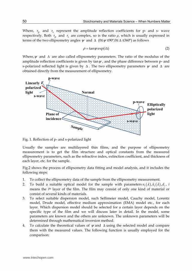
As Fig.1 shows, one beam of linearly polarized light with known wavelength, incident onto the surface of an isotropy sample, the polarization state of the incident light turns to elliptical polarization. This variation in polarization state depends on the parameters that related to the sample and light, such as the incident angle of light, the refractive index of the sample. If the sample is multilayered thin film system, the parameters will include the optical constants and thickness of each layer, etc.
For convenience, the ratio ρ of the Fresnel amplitude reflection coefficients for p- and s-polarized light is introduced and given by
p
s
r
rρ = (1)
www.intechopen.com
Stoichiometry and Materials Science – When Numbers Matter
50
Where, pr and sr represent the amplitude reflection coefficients for p- and s- wave respectively. Both pr and sr are complex, so is the ratio ρ, which is usually expressed in terms of the two ellipsometry angles ψ and Δ (0≤ψ ≤90º,0≤ Δ ≤360º) as follows
tan exp( )iρ ψ= Δ (2)
Where,ψ and Δ are also called ellipsometry parameters. The ratio of the modulus of the amplitude reflection coefficients is given by tanψ , and the phase difference between p- and s-polarized reflected light is given by Δ . The two ellipsometry parameters ψ and Δ are obtained directly from the measurement of ellipsometry.
Normal
Plane of
incidence
E
p-wave
p-wave
s-wave
s-wave
Linearly
polarized
light
Elliptically
polarized
light
Fig. 1. Reflection of p- and s-polarized light
Usually the samples are multilayered thin films, and the purpose of ellipsometry measurement is to get the film structure and optical constants from the measured ellipsometry parameters, such as the refractive index, extinction coefficient, and thickness of each layer, etc. for the sample.
Fig.2 shows the process of ellipsometry data fitting and model analysis, and it includes the following steps:
1. To collect the ellipsometry data of the sample from the ellipsometry measurement. 2. To build a suitable optical model for the sample with parameters ( ) ( ), ,i i in k dλ λ , i
means the ith layer of the film. The film may consist of only one kind of material or consist of several kinds of materials.
3. To select suitable dispersion model, such Sellimeier model, Cauchy model, Lorentz model, Drude model, effective medium approximation (EMA) model etc., for each layer. Which dispersion model should be selected for a certain layer depends on the specific type of the film and we will discuss later in detail. In the model, some parameters are known and the others are unknown. The unknown parameters will be determined through mathematical inversion method.
4. To calculate the theoretical values of ψ and Δ using the selected model and compare them with the measured values. The following function is usually employed for the comparison:
www.intechopen.com

Ellipsometry and Its Applications in Stoichiometry
51
2 2
1
1RMSE ( ) ( )
2 1
ncalc meas calc measi i i i
in m =
= Ψ − Ψ + Δ − Δ − − (3)
Where, the superscripts “meas” and “calc” represent the measured and calculated ellipsometry parameters respectively. In Eq. (3), n and m are the numbers of the measured data points and the analytical parameters, respectively. The unknown parameters in the optical model, such as film thickness or optical constants, are varied and try to produce a “best fit” to the experimental data. The best fitting results will lead to minimum of the RMSE value or a value small enough, and then the physical parameters are obtained once a good fit is achieved.
Measurement (Experimental data)
Model (Theoretical data)
Fit ( Comparison of the Experimental data
and the theoretical data)
Results (n,k,thickness,roughness,etc.)
Fig. 2. Process of ellipsometry data fitting and model analysis
From the above introduction, one may find that ellipsometry is an indirect way to get the optical constants and thicknesses of each layer for a sample. The precision of the extracted parameters by the ellipsometry measurement depends on two aspects:
1. The measurement accuracy of ψ and Δ . 2. The right model and suitable fitting method.
The general iterative algorithm which applied the most is least square method. However, the algorithm must have a suitable initial estimate, or we can not get the reasonable numerical solution. In order to determine the film parameters more quickly and accurately, genetic algorithms, simulated annealing algorithm, artificial neural network algorithm and other optimization algorithms have been gradually applied to the ellipsometric data processing. It has greatly improved the convergence speed of the fitting process.
Here, we only provide a very simple introduction about the measurement principle of ellipsometry. As for the detailed knowledge on this topic, please refer to some excellent books or references [1-7].
www.intechopen.com
Stoichiometry and Materials Science – When Numbers Matter
52
2.2 Types of ellipsometry
2.2.1 Null ellipsometer
In the 19th century and early 20th century, as the only light detector, human eyes can only detect the presence or disappearance of the signal light from a quantitative point of view, so the ellipsometers were based on null ellipsometry at that time [8-10]. The null ellipsometry is usually of PCSA structure, P, C, S and A are the polarizer, the phase compensator, the sample, and the analyzer device respectively. The order of letters shows the order components arranged in the light path along the propagation of light. The operation of null ellipsometry is to rotate the P, C and A, let the incident light intensity on the detector to the smallest, and identify a set of azimuth (P, C, A) combination. The ellipsometry parameters ψ and Δ are calculated from the azimuth combination. Automation technology had not been developed at that time, and the PCA mechanical azimuth adjustment was all manual. In order to obtain accurate azimuth, the measurement time can be up to several minutes, after the azimuth measured, manual calculation should be done based on the principles of polarized light.
In 1960s, in order to reduce the time spending in angle calibration, H. Takasaki [11] used automation servomotor technology to drive polarizer and compensator and set the azimuth of polarizers automatically. However, in this configuration, it was still unavoidable to use human eye in the azimuth reading. Of course, the subsequent ellipsometry data processing was still involved in the human. So this type of ellipsometer was only a semi-automatic ellipsometer.
In 1967, J. L. Ord et al. applied the computer to send pulses to the stepper motors, read the light intensity signals from optical detector through an analog-digital (AD) signal converter, and precisely control and record the azimuths when light intensity comes to zero [12]. The ellipsometry parameters were then calculated by computer program from the measured azimuths.
During the operation of null ellipsometer, it is necessary to change the azimuths of the polarizers or compensator through mechanical rotating of optical devices. Although the application of automation technology has improved the rotary speed, but still subject to the rotation limit of the mechanical components. Besides the mechanical method of changing the polarization state, there is a phase modulated ellipsometry that add an electro-optic modulated device to the polarized device, changing the output light’s polarization state by phase modulation. The speed of changing polarization state depends on the electro-optical effect (about several kHz), which is much higher than that of the mechanical rotation (usually 1 ~ 100Hz). In 1960s, an ADP crystal with a large electro-optic coefficient was used for phase modulation [13, 14]. In the same period, Winterbottom [15] proposed and proved a new method to achieve phase modulation by using magneto-optical Faraday effect to change the polarization state of the output light, and in 1970s H. J. Mathieu made this method come true [16]. With the support of automatic circuit control system, the ellipsometer using Faraday-effect cell obtained higher measurement speed compared with the stepper motor-driven automation null ellipsometer. In addition, in 2004, K. Postava et al. [17] applied the photoelastic modulation (PEM) crystal with photoelastic effect, which have usually been used in the phase modulation photometric ellipsometer, to the null
www.intechopen.com

Ellipsometry and Its Applications in Stoichiometry
53
ellipsometer with PCSA structure, and produced an automatic phase modulation null ellipsometer with high signal to noise ratio, high precision and high sensitivity but also fast measurement speed. However, due to the electro-optic effect and photoelastic effect of the modulator crystal are very sensitive to temperature, the phase-modulated ellipsometer must work under the conditions of constant temperature and the calibration process of coefficient of the crystal phase modulation is relatively complicated.
2.2.2 Photometric ellipsometer
In 1937, C. V. Kent and J. Lawson [18] first reported the photometric instrument with the polarizer and compensator adjusted to produce circularly polarized light on reflection from the sample. The analyzer was rotated at 40 Hz, and the pseudonull condition detected by amplifying the output of the photocell detector and listening to the 80 Hz components on a pair of headphones.
The modern type photometric ellipsometry technique, with the application of the stepper motor, photodetector and computer control system, appeared in early 1970s [19, 20]. This type of ellipsometry technique no longer needs to adjust the polarizers in the light path to a specific azimuth and make the light reach the detector for a particular polarization. One may use computer to precisely set the azimuths of polarizer, analyzer and compensator, and make the polarization state of light reaching the detector changing continuously. The signal of intensity of light with different polarization was changed to experimental data through a linear AD converter and collected by computer. The data were then analyzed based on principles of ellipsometry by computer. The ellipsometry parameters were obtained from the Fourier analysis during the data processing. All the operation (from measurement to data processing) can be performed by computer. Therefore, this photometric ellipsometer represents a fast and fully automatic measurement.
Photometric ellipsometer can be divided into phase modulation type and mechanical rotation type according to the method of continuously changing the light polarization. The phase modulated ellipsometer (PME) [21, 22] is similar to the phase modulated null ellipsometer in principle, but unlike the latter, PME works without mechanical rotation of optical devices. PME has a very high measurement speed with kHz modulation frequency. However, PME also has a fatal flaw same to phase modulated null ellipsometer: as a key component, the modulator crystal is very sensitive to temperature drift, measurement error will significantly increase if not used in constant temperature, and the entire build process is complicated, so the cost is relatively high. Mechanically rotating photometric ellipsometer can divided into rotating polarizer ellipsometer (RPE), rotating analyzer ellipsometer (RAE) [23, 24], rotating polarizer and analyzer ellipsometer (RPAE) [25, 26] and rotating compensator ellipsometer (RCE) [27]. In 1975, P. S. Hauge et al. applied rotating compensator into RCE for the first time. In the situation of fixing the polarizer and analyzer, one can measure all four Stokes vector components through rotating compensator, and this method can be used to measure all polarization states, including the complete polarization and partial polarization state. If the dual rotating compensator [28] structure is used, all sixteen Mueller matrix elements can be measured. Compensator of RCE is a quarter-wave plate, strictly speaking, valid only for a single wavelength, making it restricted in the field of multi-spectral applications once.
www.intechopen.com

Stoichiometry and Materials Science – When Numbers Matter
54
RPE, RAE and RPAE belong to the same kind of photometric ellipsometer, and they have common advantages, such as simple structure, mature, low cost, etc. But they have an obvious disadvantage: when the ellipsometry parameter Δ approaching 0°or 180°, the error of measurement would be significant. Most of the early photometric ellipsometers only rotate one of the three polarizers. RPAE is the latest invention. P and A can rotate at different speed at the same time. The rotation ratio of P to A is flexible and can be 1:2 [25, 26], 1:1 [29], etc. The advantage RPAE has but the other two do not have is that it is not necessary to know the background light intensity. So RPAE can obtain two sets of ellipsometry parameters for the absolute calibration self-consistency, which is unique for RPAE. Because the rotating polarizer is relatively far away from the detector in RPE, any small deviation in installation of polarizer will bring the light spot reaching the detector rotate around a non-central point, tend to increase measurement error. Except the application in parallel measurement, the RPE is not as useful as RAE. In addition to C. V. Kent [18], the first RAE was built in 1962 by W. Budde [23]. In 1969, B. D. Cahan developed the first automated photometric ellipsometer using RAE-based structure [24].
2.2.3 Spectroscopic ellipsometer
It can’t determine the thickness of each layer with ellipsometry parameters of single wavelength for multilayer samples. In order to determine the optical constant exactly, and to get the structure of multilayer films with enough data by ellipsometry, the spectroscopic ellipsometer (SE) has been developed. In 1975, D. E. Aspnes et al. reported an SE system based on RAE for the first time [30]. A Xe lamp and Czerny-Turner grating monochrometer were employed in the SE system. The spectral resolution was 0.2 nm. For single wavelength λ = 400 nm, the total acquisition time was 7 seconds with cycles averaged per data point =1000.
In 1984, R. H. Muller et al. developed an SE system based on Faraday Cell phase self-compensation technique [31]. A special filter with uneven thickness was employed to choose wavelength at different position when white light used as light source. According to interference theory, different point at the filter with different thickness corresponds to different central wavelength of transmittance. This method has low quality of monochromatic light, but it has a high rate for changing wavelength with speed as high as 114 nm/s, and it can take 400 sets of ellipsometry parameters for different wavelength from 370 nm to 720 nm in 3 seconds.
In 1990, Y. T. Kim et al. realized a real time spectrum measurement with the combination of RPE, prism spectrometer, and optical multichannel analyzer (OMA) [32]. It took 40 ms to finish the measurement of 128 sets of ellipsometry parameters over the whole spectrum. In 2003, this group developed a generalized ellipsometer with multichannel detecting using combination of RCE and OMA [33]. The measurement time depends on the rotating frequency of compensation device, and it can take 150 sets of ellipsometry parameters in the energy range of 2 – 5 eV in 0.25 seconds.
The spectral measurement technology has a new development with the combination of multiple gratings and two dimensional array detectors. With the development of densely folded spectral images of a charge-coupled device (CCD) spectrometer [34, 35], it is possible
www.intechopen.com

Ellipsometry and Its Applications in Stoichiometry
55
to obtain the real time spectrum with high accuracy and resolution in the collecting time of CCD without moving of the mechanical devices. H. Y. You et al. realized a fast measurement of ellipsometry parameters in visible light range with the combination of array grating spectrometer and RPAE [36]. Recently, P. H. Mao et al. reported a new type of ellipsometer using an integrated analyzer composed of 12 sub-analyzers with different azimuth angles [37]. The new method having the merits of high speed and reliability in the optical data measurement can be potentially used in the fields of real time process monitoring.
Up to date, diverse of ellipsometry has been developed, such as imaging ellipsometry [38-40], infrared spectroscopic ellipsometry [41-50], Mueller matrix ellipsometry [51-63], etc. Here, we will not make a full introduction about the developments of ellipsometry. As an example, a rotating-polarizer-analyzer ellipsometer (RPAE) will be introduced as follows.
2.3 Example: A rotating-polarizer-analyzer ellipsometer (RPAE)
Here, we take the RPAE as an example to show how an ellipsometer works. An improved spectroscopic ellipsometer by synchronous rotation of the polarizer and analyzer (RPA) was suggested, designed, and constructed many years ago [64, 65]. The configuration of RPAE is shown in Fig. 3, light goes through a fixed polarizer, a rotating polarizer, sample and a rotating analyzer before entering the detector.
Fig. 3. Optical configuration of the RPAE
For a convenient mathematical presentation, assuming that the coordinates s and p are perpendicular and parallel, respectively, to the incident plane, the azimuthal angles of both P and A are related to the s axis. Then the electric field that finally emerges from the analyzer is
[ ]
( )
0
20
0cos sin cos sin 1 0 cos sin 11 0
0sin cos sin cos 0 0 sin cos 0
cos cos sin cos sin
sf
p
s p
rA A P P P PE E
rA A P P P P
r A P r A P P E
− = − − = +
(4)
Therefore the light signal received by the detector is
www.intechopen.com

Stoichiometry and Materials Science – When Numbers Matter
56
( )
2
22 4 2 2 21 1cos cos sin sin 2 tan sin 2 sin 2 cos tan cos
4 2
fI E
A P A P A P Pη ψ ψ
∝
= + + Δ
(5)
where ┟ is an arbitrary number related to light intensity, ψ and Δ are two ellipsometry parameters. If A = 2P= ω0t, then
0 1 0 2 0 3 0 4 0cos cos2 cos3 cos 4I I I t I t I t I tω ω ω ω= + + + + (6)
where
20 b(7 3tan 2 tan cos )
4I I
ηψ ψ= + + Δ + (7a)
1 (3 tan cos )I η ψ= + Δ (7b)
22 (2 tan )I η ψ= − (7c)
3 (1 tan cos )I η ψ= − Δ
(7d)
24 (1 tan 2 tan cos )
4I
ηψ ψ= + − Δ
(7e)
In Eq. (7a), Ib is the dc background signal. Hence
( )
1 21 3 2
01 3
2 2I I I
I Iρ
+ −=
+ (8a)
( )( )
1 31 2
1 3 1 3 2
3cos
2 2
I I
I I I I I
−Δ = + + −
(8b)
or
( )
( )
1 21 3 2
01 2 4
9 22 2 4
I I I
I I Iρ
+ −=
+ + (9a)
( ) ( )
( )( )1 3 2 4
1 21 3 1 3 2
3 4 4cos
8 2
I I I I
I I I I I
+ − +Δ = + + −
(9b)
As for bulk material measured at the incident angle ┠ in the air, the dielectric constant ε of the sample can be calculated directly from the ellipsometry parameters as follows:
2
2 2 21 2
1sin sin tan i
1ρ
ε θ θ θ ε ερ
−= + = +
+ (10)
www.intechopen.com
Ellipsometry and Its Applications in Stoichiometry
57
Where ρ = tanΨ exp(i⦆). ε1, ε2 are the real part and imaginary part of the dielectric constant respectively. The refractive index n and absorption coefficient k can be obtained by:
( )1/21/22 2
1 2 112
n ε ε ε = + + (11a)
( )1/21/22 2
1 2 112
k ε ε ε = + − (11b)
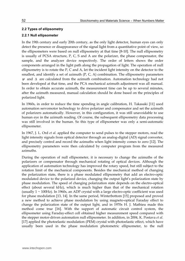
The optical system of RPAE is shown schematically in Fig. 4. A Hilger DU560 high-intensity 0.5-m-grating (1200-line/mm) monochromator produced the quasi-mono-chromatic light with a continuum light source provided by a 100 W quartz halogen filament lamp in the 350-800 nm range. The light from the lamp house was conducted by a fused-silica fiber-optic cable to the monochromator. The analyzer and two polarizers were improved types of Glan-Foucault calcite prisms, which were air-gapped in design so that the spectral response could be extended to the UV range if the short-arc xenon lamp were used. The prisms were specially made and strictly tested to have a center transmitted beam deviation of < 1 min.
Fig. 4. Schematic diagram of the optical and controlling system of the RPAE: 1, light-collimating lens; 2, the first fixed polarizer P0; 3, 4, rotating analyzer and polarizer, respectively, directly mounted on the shafts of the stepping motors; 5, stepping motors with hollow shafts; 6, light-shielding boxes; 7, sample; 8, mirrors that guide the laser beam for sample alignment; 9, rotating table connected to the arm that holds the analyzer and photomultiplier (P.M.T.); 10, rotating table connected to the sample-mounting stage; 11, fused-silica fiber-optic cable.
To have fewer parts and to avoid mechanical transmission problems entirely, the rotating analyzer A and polarizer P were directly mounted onto the motor shafts, which were
www.intechopen.com

Stoichiometry and Materials Science – When Numbers Matter
58
hollow to let light pass through. The outer and inner diameters of the shafts are 9 and 5 mm, respectively. The probe beam size is 3 mm in diameter adjusted by the axis-centered iris diaphragms. In the experiment, the analyzer and polarizer were driven synchronously by two microstepping motors with 104 microsteps/revolution, i.e., with a resolution of 0.036 deg/step, instead of with timing belts. Hence the arm, which holds the analyzer and photomultiplier, can move freely according to the incident angle set by the users. As shown in Fig. 4, the arm holding the two polarizers is fixed. The arm, on which the analyzer and photomultiplier with an S20 response are mounted, is connected to the lower rotating table. The sample stage sits on the upper rotating table. The two rotating tables are concentric. In the experiments both rotating tables are driven by two stepping motors to positions exactly coincident with the incident angle with a computer-controlled resolution of 0.001°. The entire optical system is mounted firmly on an optical vibration-isolation table.
3. Data processing for ellipsometry
Optical constants of samples are determined from the change in the polarization state by reflection (or transmission) in ellipsometry. The ellipsometry parameters (┰, ⦆) represent the amplitude ratio and phase difference between p- and s-polarization. However, ellipsometry parameters generally show complicated variations with changes in optical constants and film thicknesses for the investigated samples. Since the ellipsometry parameters can’t be related to what we interested directly, some mathematical analysis should be done to get information such as dielectric function, film thickness and so on.
3.1 Effective medium approximation
Ellipsometry is very sensitive to sample surface and interface structures. Hence, to incorporate these structures into an optical model for the investigated sample is necessary in ellipsometry data analysis. The effective medium approximation (EMA) [66] has been applied to calculating the complex refractive indices and dielectric constants of surface roughness and interface layers. In addition, the volume fractions in composite materials can be got from ellipsometry analysis using EMA.
A general equation that describes the EMA model is:
j hhj
h j hj
fY Y
ε εε ε
ε ε ε ε
−−=
+ + (12)
Where, εj and fj are the dielectric function and volume fraction, respectively of jth material. The quantities ε and εh are the dielectric functions of the effective medium and the host respectively. Y is a factor related to screening and shape of the inclusion.
According to the above EMA equation structure, the difference of different EMA models depends on the choice of the host material.
For example, the Maxwell-Garnett model just sets the first material which has the largest volume fraction to be the host material (εh=ε1) and then the EMA equation reduces to:
www.intechopen.com

Ellipsometry and Its Applications in Stoichiometry
59
11
1 1
jj
jj
fY Y
ε εε ε
ε ε ε ε
−−=
+ + (13)
The Bruggeman model assumes that the host material is just the EMA dielectric function (εh=ε) which is self-consistent. For the Bruggeman model the EMA equation reduces to:
1
1
0j
j
jj
fY
ε ε
ε ε
−=
+ (14)
The Lorentz-Lorenz model is obtained when the host material is chosen as air or vacuum (εh=1). The EMA equation reduces to:
11 j
j
jj
fY Y
εε
ε ε
−−=
+ + (15)
3.2 Dielectric function models
Optical constants are closely related to the wavelength of incident light, and it is known as the dispersion relation. In the analysis of ellipsometry data, it is an important step to select appropriate dispersion model for the investigated samples if the dielectric function is unknown.
The Lorentz oscillator model is a classical model which is usually used to describe the dispersion relation of semiconductor and crystalline materials. [6, 7, 67, 68] On the basis of this model, the dielectric function is usually expressed as
2 20
( ) 1j
j j j
AE
E E i Eε = +
− − Γ (16)
It assumes that this material is a sum of the j oscillators. In above expression, the Aj is the strength of jth oscillator in unit of eV2, ポ is the damping coefficient in unit of eV, E0j in unit of eV is the jth oscillator resonance energy and E is the energy of the light.
Sellmeier model is another model first proposed by W. Sellmeier in 1871. It is best suited to transparent materials such as SiO2, MgF2, TiO2, BK7 optical glass and so on. It can also be used for germanium, silicon, gallium arsenide, etc. in infrared spectra region. In the Sellmeier model, the dielectric function can be regarded as a special region of Lorentz model whose ε2 is 0. It can be expressed by equations:
2
21 2 2
0
j
j j
Bn A
λε
λ λ= = +
− (17a)
2 0ε = (17b)
Cauchy model is regarded as an approximate function of Sellmeier model. It was an empirical model first proposed by A. L. Cauchy. The equation of the model is expressed as:
www.intechopen.com

Stoichiometry and Materials Science – When Numbers Matter
60
2 4( ) ...
B Cn Aλ
λ λ= + + + , k=0’ (18)
The Drude model is best suited to metallic materials such as Al and Au. It tries to explain the properties of metals with the idea that electrons move free between positively charged ionic cores. The dielectric function can be expressed as:
1
( ) 1 .j
jj
BE
E E iε
= − − Γ (19)
Usually one single term is sufficient for accuracy and the following equation is used:
2
1( )
pE
E E ivε ε∞
= −
− (20)
Where, ε∞ is the high-frequency lattice dielectric constant, Ep=ħ┱p, ┱p is the plasma angular frequency and ν is the electron scattering frequency.
The Forouhi-Bloomer (F-B) theory is first proposed by A. R. Forouhi and I. Bloomer in 1986 [67]. It is applied to parameterize the optical functions of amorphous materials. In their work, they obtained the extinction coefficient k starting from the single electron model with limited excited lifetime. The extinction coefficient k is given by:
2
21
( )( )
qi g
i i i
A E Ek E
E B E C=
−=
− + (21)
Where Ai, Bi, Ci and band gap Eg are fitting parameters. Then the refractive index n determined by Kramers-Kronig integration is as follows:
0 0
21
( ) ( ) i i
q
i i i
B E Cn E n
E B E C=
+= ∞ +
− + (22)
2
20 ,
2i
i ig i g i
i
A BB E B E C
Q
= − + − + (23)
20 ( ) 2 ,
2i
i ig i g i
i
A BC E C E C
Q
= + − (24)
2 1/21(4 ) .
2i i iQ C B= − (25)
The difference between F-B model and classical models is that when E goes large, the k(E) approaches constant and the refractive index n is larger than 1. It is unphysical.
www.intechopen.com

Ellipsometry and Its Applications in Stoichiometry
61
Another model for optical functions of amorphous materials is Tauc-Lorentz (T-L) model which is first proposed by G. E. Jellison et al. in 1996 [68]. The parameterization is obtained as a combination of Tauc expression and Lorentz oscillator model for ε2 of a collection of non-interacting atoms, and ε2(E) is given by
2
02 2 2 2 2 2
0
( )( ) ( ),
[( ) ]
gg
AE E EE E E
E E E Eε
Γ −= Θ −
− + Γ
(26)
Where, E0 is the peak transition energy and ポ is the broadening parameter, Eg is the band gap and A is the prefactor. Θ is the Heaviside Theta function, where Θ(E<0)=0 and Θ(E≥0)=1.
Although the T-L expression is empirical, it is consistent with Kramers-Kronig relations and the known physical phenomena, within the limitation of the model.
3.3 Data analysis procedure
The ellipsometry data analysis procedure consists of the following steps [6,7]:
1. Constructing an optical model. In the data analysis procedure in ellipsometry, an optical model corresponding to the investigated sample structures must be constructed firstly. An optical model is represented by the complex refractive index and layer thickness of each layer, normally, it consists of an air/thin film/substrate structure. It should be decided if any layer is anisotropic at this stage, and whether or not interface layers are to be modeled as a single effective medium approximation, or is a more complicated graded interface to be used for the sample.
2. Selecting the dielectric functions model for each layer. In some cases, the existing data sets or some kind of parameterization are used. However, the dielectric functions of layers are normally not known, and the dielectric function models described in section 3.2 are employed.
3. Fitting the measured (┰, ⦆) spectra and evaluating the fitting error. When the fitting error σ is large, the optical model or dielectric functions are optimized. Finally, from the optical model and dielectric functions that minimize σ, the optical constants and film thicknesses of the sample are obtained.
Since ellipsometry is a model-based technique, therefore, the resulting best-fit model must be evaluated for fit error and physical meaningfulness. Before the data analysis in ellipsometry, it’s necessary and important to make clear the sample structures. In other words, when the optical model or film structures of the investigated sample are not known well, the resulting ellipsometry data analysis must be justified by other characterization methods. There are several techniques, such as scanning electron microscope (SEM), transmission electron microscope (TEM), and atomic force microscope (AFM) have been used to confirm sample structures established in ellipsometry data analysis procedure. This is the disadvantage of the ellipsometry technique. Fortunately, the ellipsometry analysis has a very high-precision, as soon as an analytical method for an investigated sample is established. Moreover, much more reliable ellipsometry results can be obtained, if the ellipsometry data analysis using a data set measured from different incident angles or wavelengths.
www.intechopen.com

Stoichiometry and Materials Science – When Numbers Matter
62
4. Application of ellipsometry in stoichiometry
4.1 Surface and interfaces
Ellipsometry is an optical monolayer-sensitive interface analysis method for the investigation of various aspects of surface and interfaces, including surface stoichiometry, surface roughness, adsorption, desorption, and surface strain, etc. In combination with the availability of microcomputers, SE has been developed and widely used for studies of thin films in the ambient, where parameters such as film thickness, composition, and interface roughness are determined. SE is now a popular tool for in situ growth control and diagnostics of interfaces.
Here, we will see the ellipsometry application in detecting the surface or interface stoichiometry. Aspnes and Theeten applied SE to study the in situ optical properties of the interface between Si and its thermally grown oxide [69]. They found there is an atomically mixed layer of Si and O of average stoichiometry SiO0.4±0.2, and the thickness of the interlayer is (7±2) Å. Fig. 5 shows the average stoichiometry and thickness of the Si-SiO2 interface for various substrate orientations and overlayer thicknesses. The refractive-index at λ=5461 Å for SiO0.4±0.2 has value of 3.2± 0.5. Similar research work by F. Giustino et al. also showed that there exists an off-stoichiometric SiOx(0<x<2) layer of ~ 5-7 Å between the SiO2 layer and Si substrate [70], and the suboxide region (i.e. the region containing the partially oxidized Si atoms) is of higher refractive index in comparison with that of SiO2 [71]. The results given by F. Giustino et al. agree well with those by D. E. Aspnes. The off-stoichiometry interlayer cannot be ignored, especially for ultra-thin film deposited on a substrate. Q. Y. Cai et al. studied the evolution of optical constants of silicon dioxide on silicon from ultrathin films to thick films, and found the refractive indices of ultrathin SiO2 on silicon substrate monotonically increase with decreasing thickness below 60 nm, as shown in Fig. 6 [72]. The increasing of refractive index of ultrathin SiO2 can be understood as the contribution of the off-stoichiometry silicon oxide layer which has larger refractive index.
Another important factor we are focusing on is the surface or interface roughness, which should be considered carefully to determine the measured dielectric properties of "real" materials, particularly as determined by ellipsornetry. The surface roughness layer is an equivalent mixture layer composed of substrate and ambient materials. The volume fraction of the ambient (usually voids) preset within the surface roughness layer is denoted as fvoid. Fig.7 shows the (Ψ, ⦆) spectra of crystalline silicon (c -Si) obtained from calculation by applying EMA with considering different thicknesses of the surface roughness layer (ds) [73]. In this calculation, ds was varied from 0 Å to 50 Å with a step of 10 Å. The incident angle used for the calculation was ┠0= 70°, and fvoid =0.5. The results show that the surface roughness can be detected effectively by measuring the ellipsometry parameters. A more common way to characterize the surface roughness is to employ both ellipsometry and AFM as reported by several authors [74]. Figure 8 shows the relationship between ellipsometry parameters and rms roughness obtained by calculation from AFM images. Compared with AFM, ellipsometry is regarded as a fast and nondestructive method, and can be applied to in-line measurement.
www.intechopen.com

Ellipsometry and Its Applications in Stoichiometry
63
Fig. 5. Average stoichiometry (top) and thickness (bottom) of the Si-SiO2 interface for various substrate orientations and overlayer thicknesses. After Ref. 69. Reprinted with permission from the American Physical Society, Copyright 1979.
Fig. 6. Experimental and formulated refractive indices at 550 nm for the SiO2 films with different thicknesses Loxide. After Ref. 72. Reprinted with permission from IOP Publishing, Copyright 2010.
www.intechopen.com

Stoichiometry and Materials Science – When Numbers Matter
64
Fig. 7. (Ψ, ⦆) spectra of c-Si obtained from different thicknesses of the surface roughness layer (ds). In this calculation, ds was varied from 0 Å to 50 Å with a step of 10 Å. The incident angle used for the calculation is ┠0= 70°. After Ref. 7. Reprinted with permission from John Wiley & Sons, Ltd., Copyright 2007.
Recently, SE has been extensively used for the characterization of organic materials and biomaterials [75, 76]. With the development of ellipsometry, it is now possible to obtain monolayer spectroscopy, e.g. of a protein layer at a solid/liquid interface, also to get the detailed information on the kinetics of layer formation, and monitor the adsorption processes of biomolecules in aqueous solution on a monolayer scale. With respect to organic materials, polymer thin films [77-81], self-assembled layers [82, 83], Langmuir–Blodgett (LB) films [84, 84], and liquid crystals [86, 87] have been studied intensively using spectroscopic ellipsometry. Here, we will briefly overview biomaterial characterization using the ellipsometry technique, as shown in Fig. 9 [88]. The ellipsometric spectra measured before and after protein adsorption in a porous silicon layer are given in Fig. 9a. The information both about the amount of protein adsorbed and about the adsorption depth was contained in the difference between the two spectra. Four-layer model of a porous silicon layer with human serum albumin (HAS) adsorbed in the pores, which had been achieved by analysis using multilayer models and EMA modeling, was shown in Fig.9b.
4.2 Alloys
An alloy is a homogeneous mixture, either in solution or compound, of two or more elements. Unlike chemical compound, which is formed from a chemical reaction, an alloy is formed from a physical mixture of two or more substance. For example, GaAs is obtained
www.intechopen.com

Ellipsometry and Its Applications in Stoichiometry
65
from chemical reaction and it is a compound consisting of Ga atoms bonded to As atoms. So GaAs is not an alloy. However, AlxGa1-xAs is an alloy compound consisting of AlAs and GaAs with a mole ratio of x:(1-x). SixGe1-x(0≤x≤1.0) is an alloy semiconductor, but SiC is not an physical mixture of Si and C atoms and it is a compound. An alloy with two components is called a binary alloy, and those with three, four, five components are called ternary alloy, quaternary alloy and pentanary alloy, respectively. It has different properties from those of the component elements and usually has better performances than those of materials with pure element. Semiconductor alloys provide a natural means of tuning the magnitude of the forbidden gap and other material parameters so as to optimise and widen the application of semiconductor devices. The optical properties of alloys are important parameters for their applications. SE is an excellent technique with which to investigate the optical response of semiconductors and, in particular, to measure the spectral dependence of the dielectric function. The optical properties of alloys vary with their composition, and alloy composition is an important factor used for achieving maximum tunability. The composition-dependence properties of alloys have been extensively studied using SE method. Here, we will give some examples.
Fig. 8. Correlations between ellipsometric parameters and rms roughness; data for the wet etched sample are shown as the solid squares whereas that from the thermally processed samples is shown as the open circles. ⦆vs rms roughness is shown in (a) and Ψ vs rms roughness is shown in (b). Fits to the EMA are shown as lines. After Ref. 74. Reprinted with permission from American Institute of Physics, Copyright 1996.
www.intechopen.com

Stoichiometry and Materials Science – When Numbers Matter
66
(a)
(b)
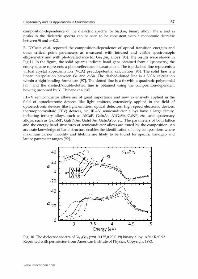
Fig. 9. (a) ⦆ vs. wavelength before (solid curve) and after (dashed curve) adsorption ofhuman serum albumin in a 288-nm thick porous silicon layer. The measurements were done in a citrate-HCl buffer (pH 4) at a protein concentration of 1 mg/ml. The angle of incidence was 68°. (b) Four-layer model of a porous silicon layer with human serum albumin (HAS) adsorbed in the pores. The voids are filled with buffer solution. The numbers to the left are the thicknesses of the sublayers. After Ref. 88. Reprinted with permission from Elsevier, Copyright 2000.
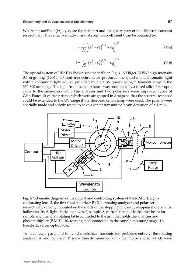
The Si1-xGex binary alloy system has been widely used in high speed heterojunction bipolar transistors (HBT) and has potential use in optoelectronic devices incorporating light sources and/or detectors [89-91]. It is very important to understand the electrical and optical properties of Si1-xGex binary alloy for using it well. The energy band gaps and optical properties of Si1-xGex binary alloy vary with its composition. C. Pickering et. al. applied SE to study thick, relaxed and thin, strained epilayers of Si1- xGex on Si in the range 0 <x <0.25 which is the range of importance for the SiGe HBT[92-94]. In Fig. 10, one may find the
300 400 500 600 700 800 900 1000
20
0
40
60
80
100
120
140
Wavelength (nm)
Del
ta (
deg
ree)
www.intechopen.com
Ellipsometry and Its Applications in Stoichiometry
67
composition-dependence of the dielectric spectra for Si1-xGex binary alloy. The εl and ε2 peaks in the dielectric spectra can be seen to be consistent with a monotonic decrease between Si and x=0.2.
R. D’Costa et al. reported the composition-dependence of optical transition energies and other critical point parameters as measured with infrared and visible spectroscopic ellipsometry and with photoreflectance for Ge1-ySny alloys [95]. The results were shown in Fig.11. In the figure, the solid squares indicate band gaps obtained from ellipsometry; the empty square represents a photoreflectance measurement. The top dashed line represents a virtual crystal approximation (VCA) pseudopotential calculation [96]. The solid line is a linear interpolation between Ge and α-Sn. The dashed-dotted line is a VCA calculation within a tight-binding formalism [97]. The dotted line is a fit with a quadratic polynomial [95], and the dashed/double-dotted line is obtained using the composition-dependent bowing proposed by Y. Chibane et al.[98].
III—V semiconductor alloys are of great importance and now extensively applied in the field of optoelectronic devices like light emitters, extensively applied in the field of optoelectronic devices like light emitters, optical detectors, high speed electronic devices, thermophotovoltaic (TPV) devices, etc. III—V semiconductor alloys have a large family, including ternary alloys, such as AlGaP, GalnAs, A1GaSb, GaNP, etc., and quaternary alloys, such as GaInNP, GaInNAs, GaInPAs, GaInAsSb, etc. The parameters of both lattice and the energy band structures of semiconductor alloys are tuned by the composition. An accurate knowledge of band structure enables the identification of alloy compositions where maximum carrier mobility and lifetime are likely to be found for specific bandgap and lattice parameter ranges [99].
Fig. 10. The dielectric spectra of Si1-xGex (x=0, 0.135,0.20,0.39) binary alloy. After Ref. 92. Reprinted with permission from American Institute of Physics, Copyright 1993.
www.intechopen.com

Stoichiometry and Materials Science – When Numbers Matter
68
Fig. 11. Composition-dependence of the direct gap E0 in Ge1−ySny alloys at room temperature. After Ref. 95. Reprinted with permission from American Physical Society, Copyright 2006.
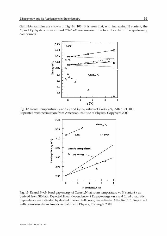
The incorporation of nitrogen into GaAs forms GaAsN, which is promising as active materials for optical-fiber communication networks. M. Schubert et al. invested the nitrogen dependence on the band structure of GaAsN alloy using SE and reported the dependence of the critical points (CPs) energies E1 and E1+⦆1 of GaAs1-yNy (0.1%<y<3.7%) on the nitrogen composition y [100]. The results are shown in Fig. 12. The dotted lines correspond to the strain-only shift of E1 and E1+⦆1. The dashed line is the alloy-only shift of E1. The dash–dotted line is the sum of strain and alloying for E1. Solid lines are linear approximations to the experimental data. With increasing nitrogen composition y, the CP energy E0 showed red shift, and the CPs E1 and E1+⦆1 blue shift. For nitrogen compositions of 0<y<1.65%, the blue shift of the E1 energy was attributed to the sum of the effects of biaxial (001) strain and alloying.
J. Wagner et al. applied SE together with resonant Raman scattering to study the GaAs1-xNx
(0<x<0.033) interband transitions involving localized and extended states. The pseudo-dielectric function spectra of GaAs1-xNx(0<x<0.033) obtained by SE showed a high-energy shift and broadening of the E1 and E1+⦆1 interband transitions with increasing N content[101]. Figure 13 shows the composition-dependence of the E1 and E1+⦆1 band-gap energies, which were determined by the minima in d2<ε2>/dE2. Ignoring strain effects, the experimental data can be fitted, using E1GaN =7.0 eV, by E1GaN =2.901+2.363×10⁻² x+1.74×10-4
x2 (eV) with the N concentration given in %. Similar results have also been reported by other authors [102, 103].
As for III–V–N alloys, taking GaAs1−xNx for an example, the incorporation of N to GaAs will induce the contraction of the lattice parameter and further reduce the bandgap. While the addition of In or Sb to GaNxAs1−x will compensate these effects. So it is possible to grow Ga1−yInyNxAs1−x or GaNxSbyAs1−x−y quaternaries that are lattice-matched to GaAs or InP and the findings are important for using these alloys for a variety of optoelectronic applications [104, 105]. The real and imaginary parts of the bulk dielectric function ε of GaAs and of three
www.intechopen.com
Ellipsometry and Its Applications in Stoichiometry
69
GaInNAs samples are shown in Fig. 14 [106]. It is seen that, with increasing N content, the E1 and E1+⦆1 structures around 2.9–3 eV are smeared due to a disorder in the quaternary compounds.
Fig. 12. Room-temperature E0 and E1 and E1+⦆1 values of GaAs1-yNy. After Ref. 100. Reprinted with permission from American Institute of Physics, Copyright 2000
Fig. 13. E1 and E1+⦆1 band gap energy of GaAs1-xNx at room temperature vs N content x as derived from SE data. Expected linear dependence of E1 gap energy on x and fitted quadratic dependence are indicated by dashed line and full curve, respectively. After Ref. 101. Reprinted with permission from American Institute of Physics, Copyright 2000.
www.intechopen.com

Stoichiometry and Materials Science – When Numbers Matter
70
Fig. 14. Real (εr) and imaginary (εi) parts of the dielectric function in GaInNAs alloys after numerical removal of the influence from the oxide layer: (a) GaAs; (b) x = 0.004, y = 0.07; (c) x = 0.0164, y = 0.05; (d) x = 0.0247, y = 0.08. Curves b, c and d are shifted by 5, 10 and 15, respectively. After Ref. 106. Reprinted with permission from IOP Publishing, Copyright 2002.
The AlGaN system can be used in light emitting diodes (LED), metal-oxide-semiconductor field-effect transistor (MOSFET), solar blind photo detectors, surface acoustic wave devices, etc. It has been reasonably well studied. M. Stutzmann et al. [107] reported on a systematic study of AlGaN alloys deposited by molecular beam epitaxy (MBE) with the aim to obtain a consistent set of data for the structural, optical and electronic properties of these alloys, which covered the entire compositional range from GaN to AlN. A UV ellipsometer at the Berlin synchrotron facility BESSY I was applied to characterize the samples, and the pseudodielectric functions of AlGaN over a wide energy range (3–17 eV) are shown in Fig. 15. In the figure, one may find that E1 and E2 transitions shift to higher energies with increasing Al content, however less pronounced than the fundamental edge transition E0. The spectra of all samples also show a yet unidentified transition at photon energy of about 13 eV. Antoine-Vincent et al. reported optical constants in the 300–600 nm range for several Al compositions of AlxGa1-xN alloy layers grown on (111) Si substrates [108]. An accurate knowledge of the refractive indices of AlGaN alloys will be helpful for effective design of devices.
Metals and their alloys have important application in information storage devices, sensors, medical devices, etc. SE is an excellent tool to measure the dielectric response functions, which contain information on the optical transitions between the occupied and unoccupied electronic band states. K. J. Kim et al. reported ellipsometric study of optical transitions in Ag1-xInx alloys in the 1.2-5.5 eV energy range, and the results are shown in Fig. 16 [109]. As In is added, one can clearly see the splitting of the two transition edges, the strong L3→L′2(EF) (d band to Fermi surface near point L) around 4.1 eV the weak L′2(EF)→L1 (Fermi surface near point L to a higher conduction band) around 3.8 eV, which were not resolved in
www.intechopen.com

Ellipsometry and Its Applications in Stoichiometry
71
pure Ag. With increasing of In concentration, the magnitude of ε2 at low photon energies increases. This can be interpreted in terms of the increased intraband scattering rate of the conduction electrons below the interband absorption edge due to the added impurities.
Fig. 15. Imaginary part of the pseudo-dielectric function measured by UV ellipsometry. After Ref. 107. Reprinted with permission from Elsevier, Copyright 1997.
Fig. 16. The ε2 spectra of various Ag1-xInx alloys. After Ref. 109. Reprinted with permission from American Physical Society, Copyright 1988.
www.intechopen.com

Stoichiometry and Materials Science – When Numbers Matter
72
4.3 Composites
SE with an EMA model is now extensively used to determine the effective refractive index, thickness, and volume fraction of thin nanocomposite films [110-112]. R. Serna et al. investigated the optical properties of Bi:Ge composite thin films using SE [113]. The films, grown on chemically cleaned Si (100) substrates at room temperature and produced by pulse laser deposition (PLD) in vacuum, were formed by Bi nanocrystals embedded in amorphous Ge matrices. The Bi:Ge films were grown with 12, 25, 50, 100, or 200 pulses on the Bi target and constant number of pulses on the Ge target (100 pulses). The SE measurement was taken with a step of 10 nm in the 300–800 nm wavelength range. The measured ellipsometry parameters of the composite films were simulated using the Bruggeman and Maxwell–Garnet EMA models in three dimensional isotropic systems considering spherical particles and a standard regression method. For comparison, the Bi content in the films was also measured by Rutherford backscattering spectrometry (RBS). Then the optical constants could be calculated from the ellipsometry parameters supposing an absorbing film lay on a crystalline silicon substrate with the thickness of thinner films (20-40 nm) determined by RBS.
Figure 17 shows the real (n) and imaginary (k) parts of the complex refractive index as a function of the wavelength for the films grown with 25 and 200 pulses on Bi per layer. Only the values of n and k for the films with 25 and 200 pulses on Bi per layer have been included for clarity. For comparison, the values of n and k for pure PLD a-Ge [114] and Bi [115] films are included in the figure. One may observe that the curves with 200 and 25 pulses on Bi per layer are close to those of pure Bi and pure a-Ge, respectively. The reason may be attributed to the increase of the crystal size [116].
Dielectric composites have potential applications in the design of optical devices or microelectronic devices [117-119]. MgO is a promising low refractive index oxide with nL of about 1.62–1.74 (at λ=550 nm) [117], while TiO2 has a relative high refractive index with nH of about 2.27–2.48 (at λ=550 nm) [118], and thus it is expected to have a tunable refractive index in the MgO–TiO2 composite films by controlling the Mg content. So the performance of the optical devices can be improved with the higher refractive index (nH-nL) and thinner thickness of the two materials [119]. It has been reported that MgO can tune the band gap of ZnO from 3.4 to 7.8 eV depending on Mg content in MgO–ZnO composite films [120]. An accurate knowledge about the properties of the dielectric composite will broaden their better application. SE is proved to be a powerful tool in the study of the optical properties of those materials.
C. Ye et al. reported the optical properties of MgO–TiO2 amorphous composite films using SE [121]. The MgO–TiO2 composite thin films were sputtered on n-type (100) Si and glass substrates at room temperature by radio frequency magnetron co-sputtering. The growth rate of the composite amorphous film increases with increasing Mg content (atomic ratio of MgO/(MgO+TiO2)). A dispersion model depending on the interband absorption of thin film is essential for data analysis. The Tauc-Lorentz model especially suitable for amorphous material [68, 122] was used to characterize dielectric function (ε=εr+iεi) of the amorphous MgO–TiO2 composite film. A three-layer optical model was constructed on Si (100) substrate, i.e., SiO2 interface layer (L1), MgO–TiO2 composite layer (L2), and a surface rough layer (L3) supposing 50% void and 50% MgO–TiO2 material in the surface rough layer and using Bruggeman EMA [123]. The best fitting results of layer thickness, Eg, and the value of
www.intechopen.com

Ellipsometry and Its Applications in Stoichiometry
73
refractive index (at λ=550 nm) were summarized in Table 1. The data in the table show that with the increase of Mg content the thickness of the surface rough layer (L3) and the composite layer (L2) increases, which indicate the increase of growth rate of thin film.
Fig. 17. (a) Real, n and (b) imaginary, k, parts of the complex refractive index as a function of wavelength, for Bi:Ge films with 25 and 200 pulses on the Bi target per layer, and for films of the pure elements (a-Ge and Bi)(see Refs. 114 and 115) grown by PLD under the same conditions for comparison. After Ref. 113. Reprinted with permission from American Institute of Physics, Copyright 1998.
Mg (%) L1(nm) L2(nm) L3(nm) L=(L2+L3)nm
n@550nm Eg(eV)SE
Eg(eV) Abs
20.2% 1.59 50.72 2.36 53.08 2.21 3.36 3.50 41.8% 2.88 54.03 3.32 57.35 2.11 3.42 3.63 51.2% 1.98 57.95 3.91 61.86 2.02 3.48 3.68 62.4% 1.55 95.22 4.61 99.83 1.96 3.80 3.73 77.4% 3.95 135.55 5.44 140.99 1.89 4.05 3.79 85.7% 6.89 197.08 6.42 203.50 1.82 4.08 3.84
Table 1. Best fitting results extracted from the simulation of SE data of MgO–TiO2 composite films with different Mg contents. [After Ref. 121.]
Figure 18a shows the refractive index in the 190–830 nm wavelength range of the composite films with different Mg contents. In the figure the refractive index for all the films first increases with the wavelength until the maximum value and then decreases. The maximum shifts to shorter wavelength with the increase of Mg content (blue shift). This same behavior has also been observed in different materials [124-126]. The inset in Fig. 18 (a) shows the linear relation between the refractive index (at λ=550 nm) and Mg content in the MgO–TiO2
www.intechopen.com

Stoichiometry and Materials Science – When Numbers Matter
74
composite films. The similar results derived from SiO2-TiO2 amorphous thin film, deposited by double electron-beam co-evaporation, show that the refractive index also decreases linearly as the content of SiO2 in the composite increases [127]. Nevertheless, in other composite thin films, such as ZnO–In2O3 and Al2O3-TiO2, there is no simple linear dependence of the refractive index on its component [128, 129]. The refractive index will be influenced by the packing density and the crystalline quality of the film. But at present, the essential reason of linear change for the refractive index is not very clear, and the possible reason might be the amorphous structure of the composite films with atom cluster mixed together to form MgO–TiO2 composite. Figure 18b shows the extinction coefficient (k) of composite films as a function of the wavelength with different Mg contents. The extinction coefficient firstly increases with the wavelength until the maximum and then decreases rapidly to zero when Mg content lower than 61.4%. While for the composite films with Mg content of 61.4% and higher, the extinction coefficient monotonously decreases until zero. Figure 18b also shows that the extinction coefficient is nearly zero at visible light region and decreases with the increase of Mg content except for the wavelength shorter than 260 nm. The wavelength at which the extinction coefficient is zero moves to short wavelength (blue shift) with the increase of Mg content. The behavior is in accord with the shift of the absorption edge which will be described below in Fig. 19. The consistency lies in the direct proportional relationship between the extinction coefficient and absorption coefficient, α=4πk/λ.
Fig. 18. Refractive index (a) and extinction coefficient (b) of MgO–TiO2 composite films with different Mg contents. The inset shows the dependence of the refractive index at 550 nm on Mg content. After Ref.121. Reprinted with permission from American Institute of Physics, Copyright 2007.
www.intechopen.com

Ellipsometry and Its Applications in Stoichiometry
75
Figure 19 shows the absorption spectra of the MgO–TiO2 composite films on glass substrate. It is observed that the absorption coefficient decreases and the absorption edge occurs blue shift with the increase of Mg content. The blue shift might derive from the quantum size effect. The optical band gap (Eg) can be obtained from a plot of (αhν)1/2 versus photon energy (hν), as shown in the inset in Fig. 19. Extrapolation of the linear portion (αhν)1/2 to zero gives value of Eg. The results are also listed in Table 1, which shows that the optical band gap of the composite film increases with the increase of Mg content. Compared with Eg extracted from T-L model in SE simulation (shown in Table 1), there are only a slight difference (less than 0.25 eV) between them. In conclusion, a wide energy band oxide MgO as an additive in TiO2 films can enlarge the optical band gap of the thin films.
Fig. 19. Absorption spectra of MgO–TiO2 composite films with different Mg contents. The inset shows the plot of (αhν)1/2 vs hν for α larger than 104 cm−1. After Ref. 121. Reprinted with permission from American Institute of Physics, Copyright 2007.
5. Conclusions
This chapter introduces the principles, measurement techniques, data analysis procedures for ellipsometry, and provides the related applications of ellipsometry, especially in the field of stoichiometry. As examples, we give an overview of the various ellipsometry applications in stoichiometry for surface and interfaces, alloys and composites, etc. It’s shown that ellipsometry, either alone or in combination with other techniques, is now a mature technique which has been successfully applied to large variety applications. There will be a bright future for ellipsometry as its combine accuracy, speed, and proven reliability with the huge advantage of nondestructive characterization.
6. Acknowledgements
The authors would like to thank the National Science Foundation (NSF) of China with the contract numbers 60778028, 60938004, 60908005, 11174058, the Science and Technology Commission of Shanghai Municipality (STCSM) project of China with the Grant No. 08DZ1204600 and the No.2 National Science and Technology Major Project of China under Contract No. 2011ZX02109-004, for financially support. D. X. Zhang, W. Lin, X. Yu, Z. J. Xu and F. Zhang are gratefully acknowledged for technical support and fruitful discussion.
www.intechopen.com

Stoichiometry and Materials Science – When Numbers Matter
76
7. References
[1] D. E. Aspnes, Spectroscopic ellipsometry of solids, chapter 15 in Optical Properties of Solids : New Developments, edited by B. O. Seraphin, North-Holland publishing company, Amsterdam(1976).
[2] R. M. A. Azzam and N. M. Bashara, Ellipsometry and Polarized Light, North-Holland, Amsterdam (1977).
[3] R. M. A. Azzam, Ellipsometry, chapter 27 in Handbook of Optics, Vol. 2, McGraw-Hill, New York (1995).
[4] H. G. Tompkins and W. A. McGahan, Spectroscopic Ellipsometry and Reflectometry:A User’s Guide, John Wiley & Sons, Inc., New York (1999).
[5] M. Schubert, Infrared Ellipsometry on Semiconductor Layer Structures: Phonons,Plasmons, and Polaritons, Springer, Heidelberg (2004).
[6] H. G. Tompkins and E. A. Irene, Eds, Handbook of Ellipsometry, William Andrew, New York (2005).
[7] H. Fujiwara, Spectroscopic Ellipsometry: Principles and applications, John Wiley & Sons, Ltd (2007).
[8] P. Drude. Über die Gesetze der Reflexion und Brechung des Lichtes an der Grenze absorbierender Kristalle. Ann. Phys., 32 (1887) 584-625.
[9] A. Rothen, The ellipsometer, an apparatus to measure thicknesses of thin surface films, Rev. Sci. Instrum., 16 (1945) 26–30.
[10] W. Paik and J. O’M. Bockris, Exact ellipsometric measurement of thickness and optical properties of a thin light-absorbing film without auxiliary measurements, Surf. Sci., 28 (1971) 61–68.
[11] H. Takasaki. Automatic Ellipsometer. Automatic Polarimetry by Means of an ADP Polarization Modulator III. Appl. Opt., 5( 1966)759-764.
[12] J. L. Ord, and B. L. Wills, A Computer-Operated Following Ellipsometer, Appl. Opt., 6(1967)1673-1677.
[13] H. Takasaki, M. Isobe, T. Masaki, A. Konda, T. Agatsuma, and Y. Watanabe, An automatic retardation meter for automatic polarimetry by means of an ADP polarization modulator, Appl. Opt., 3(1964) 345-350.
[14] H. Takasaki, N. Okazaki, and K. Kida,. An automatic polarimeter. II. Automatic polarimetry by means of an ADP polarization modulator, Appl. Opt., 3(1964)833-837.
[15] A. B. Winterbottom, in: E. Passaglia, R. R. Stromberg, J. Kruger (eds.), Ellipsometry in the Measurement of Surfaces and Thin Films, Washington, D. C.: National Bureau of Standard Miscellaneous Publication, 256(1964) 97.
[16] H. J. Mathieu, D. E. McClure, R. H. Muller, Fast self-compensating ellipsometer, Rev. Sci. Instrum., 45(1974) 798-802.
[17] K. Postava, A. Maziewski, T. Yamaguchi, R. Ossikovski, Š. Višňovský, and J. Pištora, Null ellipsometer with phase modulation, Opt. Express, 12(2004) 6040-6045.
[18] C. V. Kent, and J. Lawson, A Photoelectric Method for the Determination of the Parameters of Elliptically Polarized Light, J. Opt. Soc. Am., 27(1937) 117-119.
[19] P. S. Hauge, F. H. Dill, Design and Operation of ETA, an Automated Ellipsometer, IBM J. Res. Develop., 17(1973) 472-489.
[20] D. E. Aspnes, Fourier transform detection system for rotating-analyzer ellipsometers, Opt. Commun., 8(1973) 222-225.
[21] S. N. Japerson, and S. E. Schnatterly, An Improved Method for High Reflectivity Ellipsometry Based on a New Polarization Modulation Technique, Rev. Sci. Instrum., 40(1969) 761-767.
www.intechopen.com
Ellipsometry and Its Applications in Stoichiometry
77
[22] V. M. Bermudez, and V. H. Ritz, Wavelength-scanning polarization-modulation ellipsometry: some practical considerations, Appl. Opt., 17(1978) 542-552.
[23] W. Budde, Photoelectric Analysis of Polarized Light, Appl. Opt., 1(1962) 201-205. [24] B. D. Cahan, and R. F. Spanier, A high-speed automatic ellipsometer, Surf. Sci.,
16(1969)166-176. [25] L. Y. Chen, and D. W. Lynch, Scanning ellipsometer by rotating polarizer and analyzer,
Appl. Opt., 26(1987) 5221-5228. [26] L. Y. Chen, X. W. Feng, Y. Su, H. Z. Ma, and Y. H. Qian, Design of a scanning
ellipsometer by synchronous rotation of the polarizer and analyzer, Appl. Opt., 33(1994) 1299-1305.
[27] P. S. Hauge, F. H. Dill, A Rotating-Compensator Fourier Ellipsometer, Opt. Commun., 14(1975) 431-437.
[28] P. S. Hauge, Mueller matrix ellipsometry with imperfect compensators, J. Opt. Soc. Am., 68(1978) 1519-1528.
[29] T. M. El-Agez, A. A. El Tayyan and S. A. Taya, Rotating polarizer-analyzer scanning ellipsometer, Thin Solid Films, 518(2010) 5610-5614.
[30] D. E. Aspnes, A. A. Studna. High Precision Scanning Ellipsometer, Appl. Opt., 14(1975) 220-228.
[31] R. H. Muller, and J. C. Farmer, Fast, self-compensating spectral-scanning ellipsometer, Rev. Sci. Instrum., 55(1984) 371-374.
[32] Y. T. Kim, R. W. Collins, and K. Vedam, Fast scanning spectroelectrochemical ellipsometry: In-situ characterization of gold oxide, Surf. Sci., 233(1990) 341-350.
[33] C. Chen, I. An, and R. W. Collins, Multichannel Mueller Matrix Ellipsometry for Simultaneous Real-Time Measurement of Bulk Isotropic and Surface Anisotropic Complex Dielectric Functions of Semiconductors, Phys. Rev. Lett., 90(2003) 217402-1~217402-4.
[34] Y. R. Chen, B. Sun, T. Han, C. H. Xu, P. Zhou, X. F. Li, S. Y. Wang, Y. X. Zheng, and L. Y. Chen, Densely folded spectral images of a CCD spectrometer working in the full 200–1000 nm wavelength range with high resolution, Opt. Express, 13(2005) 10049-10054.
[35] M. H. Liu, S. X. Pan, Y. R. Chen, Y. F. Wu, Q. Y. Cai, P. H. Mao, Y. X. Zheng, and L. Y. Chen, Path-folded infrared spectrometer consisting of 10 sub-gratings and a two-dimensional InGaAs detector, Opt. Express, 17(2009) 14956-14966.
[36] H. Y. You. J. H. Jia, J. K. Chen, T. Han, W. M. Ni, S. Y. Wang, J. Li, R. J. Zhang, Y. M. Yang, L. Y. Chen, and D. W. Lynch, New design of a spectroscopic ellipsometer by using a spectrometer with multiple gratings and a two-dimensional CCD array detector, Thin Solid Films, 455-456(2004)84-89.
[37] P. H. Mao, Y. X. Zheng, Y. R. Chen, Q. Y. Cai, R. J. Zhang, and L. Y. Chen, Study of the new ellipsometric measurement method using integrated analyzer in parallel mode, Opt. Express, 17 (2009) 8641-8650.
[38] G. Jin, R. Jansson, and H. Arwin, Imaging ellipsometry revisited: Developments for visualization of thin transparent layers on silicon substrates, Rev. Sci. Instrum., 67 (1996) 2930–2936.
[39] D. Tanooka, E. Adachi, and K. Nagayama, Color-imaging ellipsometer: high-speed characterization of in-plane distribution of film thickness at nano-scale, Jpn. J. Appl. Phys., 40 (2001) 877–880.
[40] Q. Zhan and J. R. Leger, High-resolution imaging ellipsometer, Appl. Opt., 41 (2002) 4443–4450.
www.intechopen.com

Stoichiometry and Materials Science – When Numbers Matter
78
[41] R. W. Stobie, B. Rao, and M. J. Dignam, Automatic ellipsometer with high sensitivity and special advantages for infrared spectroscopy of adsorbed species, Appl. Opt., 14 (1975) 999–1003.
[42] A. S. Siddiqui and D. M. Treherne, Optical properties of some transition metals at infrared frequencies, Infrared Physics, 17 (1977) 33–42.
[43] A. Roseler, Spectroscopic ellipsometry in the infrared, Infrared Physics, 21 (1981) 349–355.
[44] A. Roseler and W. Molgedey, Improvement in accuracy of spectroscopic IR ellipsometry by the use of IR retarders, Infrared Physics, 24 (1984) 1–5.
[45] A. Roseler, IR spectroscopic ellipsometry: instrumentation and results, Thin Solid Films, 234 (1993) 307–313.
[46] F. Ferrieu, Infrared spectroscopic ellipsometry using a Fourier transform infrared spectrometer: some applications in thin-film characterization, Rev. Sci. Instrum., 60 (1989) 3212–3216.
[47] T. E. Tiwald, D. W. Thompson, J. A. Woollam, S. V. Pepper, Determination of the mid-IR optical constants of water and lubricants using IR ellipsometry combined with an ATR cell, Thin Solid Films, 313–314 (1998) 718–721.
[48] C. Defranoux, T. Emeraud, S. Bourtault, J. Venturini, P. Boher, M. Hernandez, C. Laviron, T. Noguchi, Infrared spectroscopic ellipsometry applied to the characterization of ultra shallow junction on silicon and SOI, Thin Solid Films, 455–456 (2004) 150–156.
[49] R. T. Graf, F. Eng, J. L. Koenig and H. Ishida, Polarization modulation Fourier transform infrared ellipsometry of thin polymer films, Appl. Spectrosc., 40 (1986) 498–503.
[50] A. Canillas, E. Pascual and B. Drevillon, Phase-modulated ellipsometer using a Fourier transform infrared spectrometer for real time applications, Rev. Sci. Instrum., 64 (1993) 2153–2159.
[51] P. S. Hauge, Automated Mueller matrix ellipsometry, Opt. Commun., 17 (1976) 74–76. [52] P. S. Hauge, Mueller matrix ellipsometry with imperfect compensators, J. Opt. Soc. Am.,
68 (1978) 1519–1528. [53] R. M. A. Azzam, Photopolarimetric measurement of the Mueller matrix by Fourier
analysis of a single detected signal, Opt. Lett., 2 (1978) 148–150. [54] R. M. A. Azzam, K. A. Giardina, and A. G. Lopez, Conventional and generalized
Mueller-matrix ellipsometry using the four-detector photopolarimeter, Opt. Eng., 30 (1991) 1583–1589.
[55] D. H. Goldstein, Mueller matrix dual-rotating retarder polarimeter, Appl. Opt., 31 (1992) 6676–6683.
[56] D. A. Ramsey and K. C. Ludema, The influences of roughness on film thickness measurements by Mueller matrix ellipsometry, Rev. Sci. Instrum., 65 (1994) 2874– 2881.
[57] G. E. Jellison, Jr, and F. A. Modine, Two-modulator generalized ellipsometry: experiment and calibration, Appl. Opt., 36 (1997) 8184–8189; G. E. Jellison, Jr, and F. A. Modine, Two-modulator generalized ellipsometry: theory, Appl. Opt., 36 (1997) 8190–8198.
[58] E. Compain, B. Drevillon, J. Huc, J. Y. Parey, J. E. Bouree, Complete Mueller matrix measurement with a single high frequency modulation, Thin Solid Films, 313–314 (1998) 47–52.
[59] J. Lee, J. Koh, and R. W. Collins, Multichannel Mueller matrix ellipsometer for real time spectroscopy of anisotropic surfaces and films, Opt. Lett., 25 (2000) 1573–1575.
www.intechopen.com

Ellipsometry and Its Applications in Stoichiometry
79
[60] For a review, see C. Chen, I. An, G. M. Ferreira, N. J. Podraza, J. A. Zapien, R. W. Collins, Multichannel Mueller matrix ellipsometer based on the dual rotating compensator principle, Thin Solid Films, 455–456 (2004) 14–23.
[61] A. De Martino, E. Garcia-Caurel, B. Laude, B. Drevillon, General methods for optimized design and calibration of Mueller polarimeters, Thin Solid Films, 455–456 (2004) 112–119.
[62] J. N. Hilfiker, B. Johs, C. M. Herzinger, J. F. Elman, E. Montback, D. Bryant, and P. J. Bos, Generalized spectroscopic ellipsometry and Mueller-matrix study of twisted nematic and super twisted nematic liquid crystals, Thin Solid Films, 455–456 (2004) 596–600.
[63] A. Laskarakis, S. Logothetidis, E. Pavlopoulou, and M. Gioti, Mueller matrix spectroscopic ellipsometry: formulation and application, Thin Solid Films, 455–456 (2004) 43–49.
[64] R. M. A. Azzam, A simple Fourier photopolarimeter with rotating polarizer and analyzer for measuring Jones and Mueller matrices," Opt. Commun. 25, (1978) 137-140.
[65] L. Y. Chen and D. W. Lynch, Scanning ellipsometer by rotating polarizer and analyzer, Appl. Opt. 26, (1987) 5221-5228.
[66] D. E. Aspnes, Optical properties of thin films, Thin Solid Films, 89, (1982) 249–262. [67] A. R. Forouhi and I. Bloomer, Optical dispersion relations for amorphous
semiconductors and amorphous dielectrics, Phys. Rev. B, 34 (1986) 7018–7026. [68] G. E. Jellison, Jr. and F. A. Modine, Parameterization of the optical functions of
amorphous materials in the interband region, Appl. Phys. Lett. 69 (3), (1996) 371–373. [69] D. E. Aspnes and J. B. Theeten, Optical Properties of the Interface between Si and Its
Thermally Grown Oxide, Phys. Rev. Lett. 43う1979え1046. [70] F. Giustino, A. Bongiorno and A. Pasquarello, Atomistic models of the Si (100)–SiO2
interface: structural, electronic and dielectric properties, J. Phys.:Condens. Matter, 17 (2005) S2065.
[71] J. A. Moreno, B. Garrido, P. Pellegrino, C. Garcia, J. Arbiol, J. R. Morante, P. Marie, F. Gourbilleau and R. Rizk, Size dependence of refractive index of Si nanoclusters embedded in SiO2,J. Appl. Phys., 98 (2005) 013523.
[72] Q. Y. Cai, Y. X. Zheng, P. H. Mao, R. J. Zhang, D. X. Zhang, M. H. Liu, and L. Y. Chen, Evolution of optical constants of silicon dioxide on silicon from ultrathin films to thick films, J. Phys. D: Appl. Phys., 43(2010)445302.
[73] C. M. Herzinger, B. Johs, W. A. McGahan, J. A. Woollam, and W. Paulson, Ellipsometric determination of optical constants for silicon and thermally grown silicon dioxide via a multi-sample, multi-wavelength, multi-angle investigation, J. Appl. Phys., 83 (1998) 3323–3336.
[74] S. J. Fang, W. Chen, T. Yamanaka,a) and C. R. Helms, Comparison of Si surface roughness measured by atomic force microscopy and ellipsometry, Appl. Phys. Lett. 68, (1996) 2837-2839.
[75] U. Jonsson, M. Malmqvist, and I. Ronnberg, Adsorption of immunoglobulin G, protein A, and fibronectin in the submonolayer region evaluated by a combined study of ellipsometry and radiotracer techniques, J. Colloid. Interface Sci., 103 (1985) 360–372.
[76] F. Tiberg and M. Landgren, Characterization of thin nonionic surfactant films at the silica/wafer interface by means of ellipsometry, Langmuir, 9 (1993) 927–932.
[77] Y.-T. Kim, D. L. Allara, R. W. Collins, K. Vedam, Real-time spectroscopic ellipsometry study of the electrochemical deposition of polypyrrole thin films, Thin Solid Films, 193/194 (1990) 350–360.
www.intechopen.com

Stoichiometry and Materials Science – When Numbers Matter
80
[78] C. L. Bungay, T. E. Tiwald, D. W. Thompson, M. J. DeVries, J. A. Woollam, and J. F. Elman, IR ellipsometry studies of polymers and oxygen plasma-treated polymers, Thin Solid Films, 313–314 (1998) 713–717.
[79] L. A. A. Pettersson, F. Carlsson, O. Inganas and H. Arwin, Spectroscopic ellipsometry studies of the optical properties of doped poly(3,4-ethylenedioxythiophene): an anisotropic metal, Thin Solid Films, 313–314 (1998) 356–361.
[80] C. M. Ramsdale and N. C. Greenham, Ellipsometric determination of anisotropic optical constants in electroluminescent conjugated polymers, Adv. Mater., 14 (2002) 212–215.
[81] M. Schubert, C. Bundesmann, G. Jakopic, H. Maresch, H. Arwin, N. -C. Persson, F. Zhang, and O. Inganas, Infrared ellipsometry characterization of conducting thin organic films, Thin Solid Films, 455–456 (2004) 295–300.
[82] J. P. Folkers, P. E. Laibinis and G. M. Whitesides, Self-assembled monolayers of alkanethiols on gold: comparisons of monolayers containing mixtures of short- and long-chain constituents with CH3 and CH2OH terminal groups, Langmuir, 8 (1992) 1330–1341.
[83] A. C. Zeppenfeld, S. L. Fiddler, W. K. Ham, B. J. Klopfenstein, and C. J. Page, Variation of layer spacing in self-assembled hafnium-1,10-decanediylbis(phosphonate) multilayers as determined by ellipsometry and grazing angle X-ray diffraction, J. Am. Chem. Soc., 116 (1994) 9158–9165.
[84] A. Y. Tronin and A. F. Konstantinova, Ellipsometric study of the optical anisotropy of lead arachidate langumuire films, Thin Solid Films, 177 (1989) 305–314.
[85] B. Lecourt, D. Blaudez, and J. -M. Turlet, Specific approach of generalized ellipsometry for the determination of weak in-plane anisotropy: application to Langmuir–Blodgett ultrathin films, J. Opt. Soc. Am. A, 15 (1998) 2769–2782.
[86] Ch. Bahr and D. Fliegner, Behavior of a first-order smectic-A–smectic-C transition in free-standing liquid-crystal films, Phys. Rev. A, 46 (1992) 7657–7663.
[87] M. Schubert, B. Rheinlander, C. Cramer, H. Schmiedel, J. A. Woollam, C. M. Herzinger and B. Johs, Generalized transmission ellipsometry for twisted biaxial dielectric media: application to chiral liquid crystals, J. Opt. Soc. Am. A, 13 (1996) 1930–1940.
[88] H. Arwin, “Ellipsometry on thin organic layers of biological interest: characterization and applications”, Thin Solid Films 377-378(2000)48-56.
[89] S. S. Iyer, G. L. Patton, J. M. C. Stork, B. S. Meyerson, and D. L. Harame, Heterojunction bipolar transistor using Si-Ge alloys, IEEE Trans. ED 36, (1989) 2043-2064.
[90] D. J. Robbins, P. Calcott, and W. Y. Leong, Electroluminescence from a pseudomorphic Si0.8Ge0.2 alloy, Appl. Phys. Lett. 59, (1991) 1350-1352.
[91] R. P. G. Karunasiri, J. S. Park, and K. L. Wang, Si1-xGex/Si multiple quantum well infrared detector, Appl. Phys. Lett. 59, (1991) 2588-2590.
[92] C. Pickering, R. T. Carline, D. J. Robbins, W. Y. Leong, S. J. Barnett, A. D. Pitt, and A. G. Cullis, Spectroscopic eliipsometry characterization of strained and relaxed Si1−xGex epitaxial layers, J.Appl.Phys.73 (1993)239-250.
[93] C. Pickering and R. T. Carline, Dielectric function spectra of strained and relaxed Si1−xGex alloys (x = 0–0.25), J. Appl. Phys., 75 (1994) 4642–4647.
[94] R. T. Carline, C. Pickering, D. J. Robbins, W. Y. Leong, A. D. Pitt, and A. G. Cullis, Spectroscopic ellipsometry of Si1−xGex epilayers of arbitrary composition 0 ≤ x ≤0.255, Appl. Phys. Lett., 64 (1994) 1114–1116.
[95] Vijay R. D’Costa, Candi S. Cook, A. G. Birdwell, Chris L. Littler, Michael Canonico, Stefan Zollner, John Kouvetakis, and José Menéndez , Optical critical points of thin-film Ge1−ySny alloys: A comparative Ge1−ySny/Ge1−xSix study, Physical Review B 73, (2006) 125207.
www.intechopen.com
Ellipsometry and Its Applications in Stoichiometry
81
[96] R. Ragan and H. A. Atwater, Measurement of the direct energy gap of coherently strained SnxGe1−x/Ge(001) heterostructures, Appl. Phys. Lett. 77, (2000) 3418-3420.
[97] G. He and H. A. Atwater, Interband transitions in SnxGe1−x alloys, Phys. Rev. Lett. 79, (1997) 1937-1940.
[98] K. Brunner, K. Eberl, and W. Winter, Near-Band-Edge Photoluminescence from Pseudomorphic Si1-yCy/Si Quantum Well Structures, Phys. Rev. Lett. 76, (1996) 303-306.
[99] C. B. Geller, W. Wolf, S. Picozzi, A. Continenza, R. Asahi, W. Mannstadt, A. J. Freeman, E. Wimmer, Computational band structure engineering of III–V semiconductor alloys, Appl. Phys. Lett., 79 (2001) 368-370.
[100] G. Leibiger,V. Gottschalch, B. Rheinla¨nder, J. Sik and M. Schubert, Nitrogen dependence of the GaAsN interband critical points E1 and E1+⦆1 determined by spectroscopic ellipsometry, Appl. Phys. Lett. 77, (2000) 1650-1652.
[101] J. Wagner, K. Kohler, P. Ganser, and N. Herres, GaAsN interband transitions involving localized and extended states probed by resonant Raman scattering and spectroscopic ellipsometry, Appl. Phys. Lett., Vol. 77 ( 2000) 3592-3594.
[102] J. Sik, M. Schubert,G. Leibiger and V. Gottschalch,G. Wagner, B and-gap energies, free carrier effects, and phonon modes in strained GaNAs/GaAs and GaNAs/InAs/GaAs superlattice heterostructures measured by spectroscopic ellipsometry, J. Appl. Phys., Vol. 89, (2001) 294-305.
[103] G. Leibiger, V. Gottschalch, B. Rheinla¨nder,J. Sik, M. Schubert, Model dielectric function spectra of GaAsN for far-infrared and near-infrared to ultraviolet wavelengths, J. Appl. Phys. 89, (2001) 4927-4938.
[104] S. R. Kurtz, A. A. Allerman, E. D. Jones, J. M. Gee, J. J. Banas and B. E. Hammons, InGaAsN solar cells with 1.0 eV band gap, lattice matched to GaAs, Appl. Phys. Lett., 74 (1999) 729-731.
[105] A. Wagner, C. Ellmers, F. Höhnsdorf, J. Koch, C. Agert, S. Leu, M. Hofmann, W. Stolz, and W. W. Rühle, (GaIn) (NAs)/GaAs vertical-cavity surface-emitting laser with ultrabroad temperature operation rangeAppl. Phys. Lett. 76 (2000)271-272.
[106] C. Skierbiszewski, Experimental studies of the conduction-band structure of GaInNAs alloys, Semicond. Sci. Technol., 17 (2002) 803–814.
[107] M. Stutzmann, O. Ambacher, A. Cros, M.S. Brandt, H. Angerer, R. Dimitrov, N. Reinacher, T. Metzger, R. Höpler, D. Brunner, F. Freudenberg, R. Handschuh, Ch. Deger, Properties and applications of MBE grown AlGaN, Mat. Sci. Eng., B 50 (1997) 212–218.
[108] N. Antoine-Vincent, F. Natali, M. Mihailovic, A. Vasson, J. Leymarie, and P. Disseix,D. Byrne, F. Semond, and J. Massies, Determination of the refractive indices of AlN, GaN, and AlxGa1-xN grown on (111) Si substrates, J. Appl. Phys. 93, (2003) 5222-5226.
[109] K. J. Kim, L. Y. Chen, and D. W. Lynch, Ellipsometric study of optical transitions in Ag1-xInx alloys, Phys. Rev. B, 38 (1988) 13107-13112.
[110] D. E. Aspnes, in Handbook of Optical Constants of Solids, edited by E. D. Palik, Academic Press, Orlando, FL, Chap. 5, (1985) 89–112.
[111] F. Vega, J. C. G. de Sande, C. N. Afonso, C. Ortega, and J. Siejka, Optical properties of GeOx films obtained by laser deposition and dc sputtering in a reactive atmosphere. Appl. Opt., 33 (1994) 1203-1208.
[112] J. C. de Sande, F. Vega, C. N. Afonso, C. Ortega, and J. Siejka, Optical properties of Sb and SbOx films, Thin Solid Films, 249 (1994) 195-200.
www.intechopen.com

Stoichiometry and Materials Science – When Numbers Matter
82
[113] R.Serna, J. C. G. de Sande, J. M. Ballesteros and C. N. Afonso, Spectroscopic ellipsometry of composite thin films with embedded Bi nanocrystals, J. Appl. Phys., 84(1998) 4509-4516.
[114] J. C. G. de Sande, C. N. Afonso, J. L. Escudero, R. Serna, F. Catalina, and E. Bernabeu, Optical properties of laser-deposited a-Ge films: a comparison with sputtered and e-beam-deposited films, Appl. Opt., 31 (1992) 6133-6138.
[115] J. C. G. de Sande, T. Missana, and C. N. Afonso, Optical properties of pulsed laser deposited bismuth films, J. Appl. Phys., 80 (1996) 7023-7027.
[116] R. Serna, T. Missana, C. N. Afonso, J. M. Ballesteros, A. K. Petford- Long, and R. C. Doole, Bi nanocrystals embedded in an amorphous Ge matrix grown by pulsed laser deposition, Appl. Phys. A, 66 (1998) 43-47.
[117] K. H. Nam and J. G. Han, Microstructure and optical properties of MgO films synthesized by closed-field unbalanced magnetron sputtering with additional electron emission, Surf. Coat. Technol. 171 (2003) 51-58.
[118] H. Poelman, D. Poelman, D. Depla, H. Tomaszewski, L. Fiermans, and R.De Gryse, Electronic and optical characterization of TiO2 films deposited from ceramic targets, Surf. Sci., 482–485 (2001) 940-945.
[119] L. Martinu and D. Poitras, Plasma deposition of optical films and coatings: A review, J. J. Vac. Sci. Technol. A, 18 (2000) 2619-2645.
[120] J. S. Chen, S. Chao, J. S. Kao, H. Niu, and C. H. Chen, Mixed films of TiO2—SiO2 deposited by double electron-beam coevaporation, Appl. Opt., 35 (1996) 90-96.
[121] C. Ye, S. S. Pan, X. M. Teng, and G. H. Li. Optical properties of MgO–TiO2 amorphous composite films. J. Appl. Phys., 102 (2007) 013520.
[122] R. W. Collins, J. Koh, H. Fujiwara, P. I. Rovira, A. S. Ferlauto, J. A. Zapien, C. R. Wronski, and R. Messier, Recent progress in thin film growth analysis by multichannel spectroscopic ellipsometry, Appl. Surf. Sci., 154-155(2000)217-228.
[123] D. A. G. Bruggemann, Berechnung verschiedener physikalischer Konstanten von heterogenen Substanzen. I. Dielektrizitätskonstanten und Leitfähigkeiten der Mischkörper aus isotropen Substanzen, Ann. Phys., 416 (1935) 636-664.
[124] D. Franta, I. Ohlídal, and D. Petrýdes, Optical characterization of TiO2 thin films by the combined method of spectroscopic ellipsometry and spectroscopic photometry, Vacuum, 80 (2005) 159-162.
[125] M. Serenyi, T. Lohner, P. Petrik, and C. Frigeri, Comparative analysis of amorphous silicon and silicon nitride multilayer by spectroscopic ellipsometry and transmission electron microscopy. Thin Solid Films, 515 (2007) 3559-3562.
[126] X. H. Wang, J. L. Shi, Y. Yang, G. J. You, Y. Liu, J. Mi, and S. X. Qian, Synthesis and optical properties of PbS/ZnO composite films, J. Appl. Phys., 95 (2004) 4791-4794.
[127] J. S. Chen, S. Chao, J. S. Kao, H. Niu, and C. H. Chen, Mixed films of TiO2-SiO2 deposited by double electron-beam coevaporation, Appl. Opt., 35 (1996) 90-96.
[128] D. H. Kuo and K. H. Tzeng, Characterization and properties of r.f.-sputtered thin films of the alumina–titania system, Thin Solid Films, 460 (2004) 327-334.
[129] H. EI Rhaleb, A. E. Naciri, R. Dounia, L. Johann, A. Hakam, and M. Addou, Spectroscopic ellipsometry characterization of ZnO-In2O3 systems. Thin Solid Films, 455–456 (2004) 384-387.
www.intechopen.com
Stoichiometry and Materials Science - When Numbers MatterEdited by Dr. Alessio Innocenti
ISBN 978-953-51-0512-1Hard cover, 436 pagesPublisher InTechPublished online 11, April, 2012Published in print edition April, 2012
InTech EuropeUniversity Campus STeP Ri Slavka Krautzeka 83/A 51000 Rijeka, Croatia Phone: +385 (51) 770 447 Fax: +385 (51) 686 166www.intechopen.com
InTech ChinaUnit 405, Office Block, Hotel Equatorial Shanghai No.65, Yan An Road (West), Shanghai, 200040, China
Phone: +86-21-62489820 Fax: +86-21-62489821
The aim of this book is to provide an overview on the importance of stoichiometry in the materials science field.It presents a collection of selected research articles and reviews providing up-to-date information related tostoichiometry at various levels. Being materials science an interdisciplinary area, the book has been divided inmultiple sections, each for a specific field of applications. The first two sections introduce the role ofstoichiometry in nanotechnology and defect chemistry, providing examples of state-of-the-art technologies.Section three and four are focused on intermetallic compounds and metal oxides. Section five describes theimportance of stoichiometry in electrochemical applications. In section six new strategies for solid phasesynthesis are reported, while a cross sectional approach to the influence of stoichiometry in energy productionis the topic of the last section. Though specifically addressed to readers with a background in physical science,I believe this book will be of interest to researchers working in materials science, engineering and technology.
How to referenceIn order to correctly reference this scholarly work, feel free to copy and paste the following:
Yu-Xiang Zheng, Rong-Jun Zhang and Liang-Yao Chen (2012). Ellipsometry and Its Applications inStoichiometry, Stoichiometry and Materials Science - When Numbers Matter, Dr. Alessio Innocenti (Ed.), ISBN:978-953-51-0512-1, InTech, Available from: http://www.intechopen.com/books/stoichiometry-and-materials-science-when-numbers-matter/ellipsometry-and-its-application-in-stoichiometry

© 2012 The Author(s). Licensee IntechOpen. This is an open access articledistributed under the terms of the Creative Commons Attribution 3.0License, which permits unrestricted use, distribution, and reproduction inany medium, provided the original work is properly cited.