elo device management® remote management: elo displays · elo interactive digital signage products...
TRANSCRIPT

Elo Interactive Digital Signage products support technology that greatly simplifies remote management and diagnostics. With appropriate software implementation, it will reduce on-premise support calls and help maintain a consistent user experience.
This application note discusses all local interfaces to the IDS display. Two methods are possible: over the video signal using the VESA DDC/CI protocol and over USB using the MDC protocol. The VESA protocol enables the full functionality found in the Elo Display Device Client while the MDC protocol provides backward compatibility to the 00 series remote management features.
Overview
Elo’s Interactive Digital Signage (IDS) products are available in 32" to 70" and include the thinnest (3-3.5") all-in-one
commercial touch displays on the market.
Touchscreen Signage and Large Format Open Frames
Application Notes
Elo Device Management®Remote Management: Elo Displays
MonitorVESA DDC/Ci RS232 (Multi-Display Channel “MDC”)
HDMI VGA DisplayPort Touch USB cable (Virtual Serial) Y-Cable on VGA Physical Serial Cable
Current IDS Monitors
3202L
Yes Yes Yes
Yes Yes No
4202L Yes Yes No
4602L Yes Yes No
5501LT Yes Yes No
5551L Yes No Yes
5502L Yes Yes No
7001LT Yes Yes No
Large Format Open Frame Monitors
3243L
Yes Yes Yes No No No4243L
4343L
5543L
Discontinued Models
3201L
Yes Yes Yes Yes No No4201L
5501L
7001L
Note: .NET framework is 4.0 or above is required for Microsoft framework.

All Elo Touchscreen Signage support the Eloview MDC protocol. This provides device control/status via the monitor USB interface. For Elo customers who have utilized the IDS 00 series MDC remote management capabilities, this enables seamless backward compatibility with all Elo Touchscreen Signage monitors. Access to the MDC protocol via a virtual com port is provided by the Elo driver. Remote management functions and command set protocols are the same as with the 00 series.
I. MDC Protocol
Elo Touchscreen Signage has a USB connector which allows access to touch, MDC functionality and other peripheral devices (e.g., web cam and RFID reader) connected to the unit. This is implemented through an internal USB hub. MDC functions are implemented on a virtual serial port. If you are using an Elo Computer Module you can skip steps 1 through 3.
Step 1: The Elo VCP driver is required to be loaded. This can be downloaded from http://www.elotouch.com/Support/Downloads/dnld.asp (part of driver pack for IDS Computer Modules ECMG2).
Step 2: Connect the monitor touch USB cable to the host computer.
Step 3: In the On-Screen Display of the IDS monitor, navigate to “MDC Protocol” and select “Virtual Serial”.
Connections and Setup
Step 4: Select the virtual serial port on the Host computer. Procedure for Windows: In Control Panel, open Device Manager. Under the Ports (COM and LPT) group, you will see a “Silicon Labs CP210x USB to UART Bridge (COMXX)” listed. With XX being the available Serial (COM) port number which the ELO VCP driver has been mapped. The application (e.g., content player) that is managing the device should send hardware control commands to this port.
Video Cable
Virtual Serial
Video Cable
Physical Serial Connection
RS232 -VGA - Y-Cable
Native Serial for IDS02
and 7001LT monitors
USB Cable
Serial Cable
RS232 VGA
Application Notes
Summary of Functions Control Monitor
Brightness ✓ ✓Contrast ✓ ✓Audio ✓ ✓Auto Adjust Video ✓Restore Defaults ✓Touch Controls On/Off ✓ ✓Display Power On/Off ✓ ✓Power-on Hours ✓Backlight-on Hours ✓Serial Number ✓Command Set Supported by Device ✓Switch Input Source ✓ ✓Adjust Audio Volume by % ✓ ✓Switch Input Video and Audio Source ✓ ✓Fan Status ✓ ✓System Temperature ✓Alarm ✓

Application Notes
All values are big-endian. The required format to send commands is described below.
Command Set Format
Position 1 2 3 4 5 6 7 8 9
Description: StartHostaddress
LengthTargetAudience
CommandR/W Format
CommandType
Write Value Checksum Stop
Format for Host PC Commands:
Position 1 2 3 4 5 6 7 8 9
Description: StartHostaddress
LengthSlaveAddress
RequestedR/W Format
RequestedType
ReturnData
Checksum Stop
Format for IDS Display Response to a Host PC Read Command:
Position 1 2 3 4 5 6 7 8 9
Description: StartHostaddress
LengthSlaveAddress
Error CodeRequestedCommand
Checksum Stop Stop
Format for IDS Display Response to a Host PC Write Command:
Start
Value: always 02h
Host Address
Value: always 6Eh
Length
Value: variable number that represents the number of bytes
between LENGTH and CHECKSUM (non-inclusive). Range of
allowable values is between 80h and FFh. 80h means 0 bytes
of length, FFh means 127 bytes of length.
Target Audience
Value: Value depends on target.
If the target is all connected IDS displays (for the GET SERIAL
NUMBERS command), the value is FFh.
If the target is one specific IDS display (for all other
commands), the value is 10 ASCII bytes representing that
specific display’s 10-character serial number. For example, if
the serial number of the target display is G10C987654, then the
TARGET AUDIENCE would be: 47h 31h 30h 43h 39h 38h 37h 36h
35h 34h
Write Value
Value: depends if the COMMAND R/W FORMAT is
Read or Write.
If the COMMAND R/W FORMAT is Read, this field does not exist.
If the COMMAND R/W FORMAT is Write, this field exists. See the
COMMAND TYPE description for details of each COMMAND
TYPE’s intended/allowable WRITE VALUE.
Return Data
This field reports variable-length data from a Read command
(representing things like current brightness, on/off status).
See the COMMAND TYPE description for details of each
COMMAND TYPE’s RETURN DATA
Error Code
This field reports a 1-byte error code from a Write command:
04h – No Error
01h – COMMAND TYPE not supported by slave
00h, 02h, 03h, or 05h - Error

Application Notes
Slave Address
From Host to IDS:
If the target is all connected IDS systems, the value is FFh.
If the target is one specific IDS system (for all other
commands), the value is 10 ASCII bytes representing that
specific system’s 10-character serial number. For example, if
the serial number of the target system is G10C987654, then the
TARGET AUDIENCE would be: 47h 31h 30h 43h 39h 38h 37h 36h
35h 34h
From IDS System Response to a Host PC Command:
The value is 10 ASCII bytes representing that specific system’s
10-character serial number.
Command R/W Format
Value: Depends if the command will be a Read or a Write.
If command is a Read, then the value is 01h
If command is a Write, then the value is 04h
See the command section for details
Requested R/W Format
Value: depends if the COMMAND R/W FORMAT is
Read or Write
If the Host PC’s COMMAND R/W FORMAT was Read, the value
is the same as the Host PC’s COMMAND R/W FORMAT.
If the Host PC’s COMMAND R/W FORMAT was Write, this field
does not exist.
Requested Command
Value: depends if the COMMAND R/W FORMAT is Read or
Write
If the Host PC’s COMMAND R/W FORMAT was Read, the value
is the same as the Host PC’s COMMAND R/W FORMAT.
If the Host PC’s COMMAND R/W FORMAT was Write, this field
does not exist.
Checksum
Value: the checksum for the data between the START and
CHECKSUM fields, non-inclusive.
Stop
Value: always 03h
Value: select from the following options:
Command Reference
Function Command Type Value
R/W Options Function (For Writes) WRITE VALUE (For Write Commands RETURN VALUE (For Read Commands)
Recalldefaults
04h WRestores brightness, contrast, volume, and Analog VGA videotiming parameters to factory defaults
01h00h: Recall function not active:no action taken01h: All settings recalled
ChangeBrightness
10h R/W
For Read commands:slave will return its current brightness setting in RETURN DATA
For Write commands: slavewill set its brightness settingaccording to the WRITE VALUE
2 Byte setting:00h 00h (minimum)FFh FFh (maximum)(High Byte of setting – Low Byte of setting)
Returns 4 bytes:2 bytes for max adjustablevalue (high byte followed bylow byte) Followed by2 bytes for current value(high byte followed by low byte)
ChangeContrast
12h R/W
For Read commands: slave willreturn its current contrast settingin RETURN DATA
For Write commands: slave will set its contrast setting according to the WRITE VALUE
2 Byte setting:00h 00h (minimum)FFh FFh (maximum)(High Byte – Low Byte)
Returns 4 bytes:2 bytes for max adjustablevalue (high byte followed bylow byte) Followed by2 bytes for current value(high byte followed by low byte)
PerformAuto-Adjust
1Eh R/W
Automatically adjusts inputAnalog VGA video for optimumdisplay on the display. NOTE: IDSdisplays with Elo IDS ComputerModules use digital HDMI video
N/A – this field does not exist forthis command
00h: auto-adjust not active –no action taken01h: Auto-adjust performed

Application Notes
Value: select from the following options:
Command Reference
Function Command Type Value
R/W Options Function (For Writes) WRITE VALUE (For Write Commands RETURN VALUE (For Read Commands)
SwitchInputsource
60h R/W Switch Input source
0x80: External VGA port0x20: External HDMI port0x10: External HDMI2Note:Data size: From Host to PIDWrite = 16 bytes from S1 to below Byte’ 0Read = 12 bytes from S1 to CMDA possible value is selected by setting thecorresponding bit = 1.Setting more than one bit = 1 is invalidand must be ignored by the display. Usedto select the active video source.Byte' 0:Bit 7 External VGA portBit 6 Reserved, must be ignoredBit 5 External HDMI portBit 4 ECM-HDMI portBits 3→0 Reserved, must be ignored
Data size: From PID reply to HostWrite = 12 bytes from S1 to CMDRead = 16 bytes from S1to below Byte’ 0
Adjust Audiovolume bypercentage
61h R/W
For Read commands: slavewill return its current volumepercentage and max percentage in RETURN DATA
For Write commands: slave will set its volume setting accordingto the WRITE VALUE
2-byte setting:First byte for volume increase or reduce(00h: increase, 01h: reduce) Second bytefor volume percentage, from 1h to 5h
Returns 2 bytes:First byte for max percentage(from 0h up to 64h)Second byte for currentpercentage (from 0h to 64h)
ChangeAudioVolume
62h R/W
For Read commands: slave willreturn its current volume settingin RETURN DATA
For Write commands: slave willset its volume setting accordingto the WRITE VALUE
2-byte setting:00h 00h (minimum)FFh FFh (maximum)(High Byte – Low Byte)
Returns 4 bytes:2 bytes for max adjustablevalue (high byte followed bylow byte) Followed by2 bytes for current value (highbyte followed by low byte)
Switch InputVideo andAudio source
65h R/WSwitch Input video andaudio source
0x80: External VGA port, Audio fromPC line-in0x20: External HDMI port, Audio fromHDMI0x10: ECM-HDMI port, Audio fromECMHDMINote:Data size: From Host to PIDWrite = 16 bytes from S1 to below Byte’ 0Read = 12 bytes from S1 to CMDA possible value is selected by setting thecorresponding bit = 1.Setting more than one bit = 1 is invalidand must be ignored by the display.Used to select the active video source.Byte’ 0:Bit 7 External VGA portBit 6 Reserved, must be ignoredBit 5 External HDMI portBit 4 ECM-HDMI portBits 3→0 Reserved, must be ignored
Data size: From PID reply to HostWrite = 12 bytes from S1 to CMDRead = 16 bytes from S1 tobelow Byte’ 0
System Temp B1h R0: 0 degree C32: 50 degree C64: 100 degree C
Get LifetimeInformation
C0h R
Requests the slave to reporttwo values:1. How many accumulated hoursthe system has been on(includes SLEEP)2. How many accumulatedhours the system’s backlighthas been on.
N/A – this field does not exist forthis command
Returns 4 bytes:2 bytes for accumulated displaypower hours (high byte first,maximum of FFh FFH 65025 hrs)Followed by 2 bytes forbacklight on hours (high bytefirst, maximum of FFh FFH65025 hrs)

Application Notes
Function Command Type Value
R/W Options Function (For Writes) WRITE VALUE (For Write Commands RETURN VALUE (For Read Commands)
Control TouchFunctionality
C7h R/W
For Read commands: slave willreturn whether or not touchfunctionality is turned onFor Write commands: slave willturn touch functionality on or offaccording to the WRITE VALUE
00h (turn touch off)01h (turn touch on)
00h: touch function is off01h: touch function is on
ControlSystem Power
D6h R/W
For Read commands: slave willreturn whether or not the IDSsystem is turned on. For Writecommands: slave will power thesystem on or off according to theWRITE VALUENOTE: This function will notwork if the Host PC is an Elo IDSComputer ModuleNOTE: The system can be an IDSmonitor by itself or an IDSmonitor with integratedComputer Module.
04h (turn display off)01h (turn display on)
04h: display is off01h: display is on
Get SerialNumbers
E2h R
All IDS systems connected tothe bus report their serialnumber. This allows Host PCsoftware to address uniqueIDS systems.
N/A – this field does not exist forthis command
10 ASCII-coded hex bytesrepresenting that specificdisplay’s 10-characterserial number
GetCommandSet
F3h R
Addressable (by serial number)to only one connected systemat a time. The slave reportsthe list of commands that itshardware supports.
N/A – this field does not exist for thiscommand
A list of COMMAND TYPESsupported by the slave,excluding the “Get CommandSet” command.For example, if the slave systemsupports Get Command Set,Get Serial Numbers, ControlSystem Power, and ControlTouch Functionality, then thisfield would return 3 bytes:E2h D6h C7h
The following provides an example transaction between the host PC and IDS display.
Host PC Command:
Get Serial Numbers: 02 6E 83 FF 01 E2 D3 03
IDS Display Response:
Serial Number Response: 02 6E 8D 00 01 E2 48 31 31 43 30 32 31 39 30 32 F9 03
Notes about command timing:
1. After issuing a GET SERIAL NUMBERS command, the Host PC should wait at least 5 seconds before issuing the next command.
This should give all slaves on the bus enough time to respond.
2. After issuing any other command, the Host PC should wait at least 50ms before issuing the next command. This should give the
addressed slave enough time to respond.
Contact the technical support center nearest you for more information on Elo IDS displays:
http://www.elotouch.com/Support/TechnicalSupport/tech.asp
Command Reference

All EloTouchscreen Signage support the Eloview VESA DDC/ CI protocol. This provides device control/status via the monitor digital video interfaces (HDMI, VGA and DisplayPort). This protocol is employed by the Eloview Device Client but it can also be utilized to provide local custom applications as required.
II. VESA DDC/CI Protocol
Summary of Functions Control Monitor
Brightness ✓ ✓Contrast ✓ ✓Sharpness ✓ ✓Select Color Temperature ✓ ✓Adjust Red/Green/Blue Gain ✓ ✓Black Level of Red/Green/Blue ✓ ✓Auto Color ✓ ✓Save Color ✓Sub Contrast ✓Auto Adjustment ✓ ✓Adjust Horizontal/Vertical/Phase Position ✓ ✓
Timing Index ✓ ✓Get Timing Request ✓Adjust Clock ✓ ✓Aspect Ratio ✓ ✓Image Rotation ✓Horizontal/Vertical Frequency ✓Volume ✓ ✓Speaker Select ✓ ✓Audio Mute ✓ ✓New Control Value ✓ ✓Restore Factory Defaults ✓Power Mode ✓ ✓Touch Switch ✓ ✓Input Source ✓ ✓ Ambient Light Sensor ✓ ✓
Summary of Functions Control Monitor
OSD Enable ✓ ✓OSD Language ✓ ✓OSD Display Switch ✓Output Select ✓ ✓Temperature Value ✓Load Color Temperature Value ✓Factory Menu ✓Fan Status ✓ ✓Save User Setting ✓Save Monitor SN ✓Get Monitor SN ✓Get/Save Monitor PN ✓ ✓Get/Save Touch SN ✓ ✓Get Serial Number ✓Get Command Set ✓System Temperature ✓CPU Temperature ✓Display Usage Time ✓Alarm ✓Flat Panel Type ✓Monitor Type ✓Display Controller Type ✓Firmware Revision ✓VCP Version ✓Panel Name ✓GPIO Control ✓ ✓
Video Cable
DDC/Ci can communicate directly over the video channel.
Application Notes

Open the OSD and in the General Settings, select the IIC connection under the MDC protocol in order to use the DDC/Ci commands.
For available commands, refer to the Elo App Note EloView Remote Management:
Any application that can send and receive VESA DDC/Ci commands can be used. Examples are the applications DisplayTune and softMCCS.
OSD Setting
The command set format used follows the VESA (Video Electronics Standards Association) Display Data Channel Command Interface (DDC/CI) Standard Version 2.
Command Set Format
The following table provides Command Code definition with Elo defined data referenced in the description column.
Command Reference
Code Code Name Elo Usage Code Type Description
02h New Control Value New Value R/W
Used to indicate that a display’s user control(s) (excluding power control) has been used to change a control value.
Byte: SL
00h Reserved, must be ignored
01h No new control value(s)
02h One or more new control value(s) has been saved
03h → FEh Reserved, must be ignored
FFh No user controls are present
All changes made using the controls on the display must be reported even if these values have not been saved. The new control value must be reported to a host request for the current control value (i.e. a “GetVCP” command) A value = 02h must only be reset to a value = 01h by a host write operation and not by the display Support of this code is a mandatory requirement for compliance with MCCS standard Version 2 and higher
04h Restore Factory Defaults Recall default W
Restore all factory presets including luminance / contrast, geometry, color and TV defaults. Any non-zero value causes defaults to be restored. A value of zero must be ignored.
05h Restore Factory Luminance/Contrast Defaults Recall Factory Mode W
Restores factory defaults for luminance and contrast adjustments.Any non-zero value causes defaults to be restored.A value of zero must be ignored.
06hRestore Factory GeometryDefaults
Geometry Reset WRestore factory defaults for geometry adjustments.Any non-zero value causes defaults to be restored.A value of zero must be ignored.
07h Get Timing Request Get Timing Request R
Get H Frequency and V Frequency ValueH Frequency’s unit : K HzV Frequency’s unit: HzMHML: H frequencySHSL: V frequencyReturn 0x00 when no active display
Application Notes

Application Notes
Code Code Name Elo Usage Code Type Description
0Eh Clock Adjust Clock R/WIncreasing (decreasing) this value will increase (decrease) the videosampling clock frequency
10h Luminance Brightness R/WIncreasing (decreasing) this value will increase (decrease) the Luminanceof the image.
12h Contrast Contrast R/W
Increasing (decreasing) this value will increase (decrease) the Contrast ofthe image.Notes:1) The actual range of contrast over which this control applies is definedby the manufacturer.2) Care should be taken to avoid the situation where the contrast ratioapproaches 0 … this may be non-recoverable since user will not be ableto see the image.
14h Select Color Preset Select Color Temperature R/W
Select a specified color temperature. This is a 2 byte value, the MH bytedefines the tolerance associated with any preset … this is fixed by thedisplay manufacturer. If no tolerance level is specified, the presets mustbe interpreted as relative values supporting a scale which can move towarmer (lower color temperature) or cooler (higher color temperature).
Byte: MH
00h No tolerance is specific, treat as relative scale.
01h A tolerance of 1% is specified
02h A tolerance of 2% is specified
03h ↓09h No user controls are present
0AH A tolerance of 10% is specified
≥ 0Bh Reserved, must be ignored
SL
If MH byte ≠ 00h If MH byte = 00h
00h Reserved, must be ignored
Reserved, must be ignored
01h sRGB sRGB
02h Display native Display native
03h 4000 K Warmer
04h 5000 K ↑05h 6500 K ↑06h 7500 K |07h 8200 K |08h 9300 K ↓09h 10000 K ↓0Ah 11500 K Cooler
0Bh User 1 User 1
0Ch User 2 User 2
0Dh User 3 User 3
≥ 0EhReserved, mustbe ignored
Reserved, mustbe ignored
16h Video Gain (Drive): Red Adjust Red Gain R/W
Increasing (decreasing) this value will increase (decrease) the luminanceof red pixels.The value returned must be an indication of the actual red gain at thecurrent color temperature and not be normalized.Elo defined: If enter factory menu, maximum value will be 0xFF.
18h Video Gain (Drive): Green Adjust Green Gain R/W
Increasing (decreasing) this value will increase (decrease) the luminanceof green pixels.The value returned must be an indication of the actual green gain at thecurrent color temperature and not be normalized.Elo defined: If enter factory menu, maximum value will be 0xFF.
1Ah Video Gain (Drive): Blue Adjust Blue Gain R/W
Increasing (decreasing) this value will increase (decrease) the luminanceof blue pixels.The value returned must be an indication of the actual blue gain at thecurrent color temperature and not be normalized.Elo defined: If enter factory menu, maximum value will be 0xFF.

The following table provides Command Code definition with Elo defined data referenced in the description column.
Command Reference
Application Notes
Code Code Name Elo Usage Code Type Description
1Eh Auto Setup Auto Adjustment R/W
Perform auto setup function (H/V position, clock, clock phase, A/Dconverter, etc)
Byte: SL
00h Auto setup is not active
01h Perform / performing auto setup
02h Enable continues / periodic auto setup
≥ 03h Reserved, must be ignored
Note: A value of ‘02h’ (when supported) must cause the display to eithercontinuously or periodically (event or timer driven) perform an auto setup.Cancel by writing a value of either ‘01h’ or ‘00h’.
20h Horizontal Position (Phase) Adjust Horizontal Position R/WIncreasing (decreasing) this value moves the image toward the right (left)side of the display.
30h Vertical Position (Phase) Adjust Vertical Position R/W Increasing (decreasing) this value moves the image toward the top (bottom) edge of the display.
3Eh Clock Phase Adjust Phase Position R/WIncreasing (decreasing) this value will increase (decrease) the phase shiftof the sampling clock.
60h Input Source Input Source R/W
A one byte write/read (Byte 0), allows the host to set (write) one and onlyone input as ‘the source’ and identify (read) the current input setting.
Byte: SL
0x01 VGA
0x0F External Display Port
0x10 ECM-DP
0x11 ExternalHDMI-1
0x12 External HDMI-2
0x13 ECM-HDMI
62h Audio: Speaker Volume Volume Adjust R/W R/W
Allows the volume to be adjusted.
Byte: SL
00h Fixed (default) level
01h→FEh Volume level
FFh Mute
Note:The level will increase from a minimum at a value = 01h to a maximum ata value = FEh
63h Speaker Select Speak Select R/W
Allows a “pair” (may be physically more than two speakers) of speakersto be selected.
Byte: SL
00h Fixed (default) level
01h Volume level
02h Mute
03h Center / Sub woofer
04h→FFH Reserved, must be ignored
66h Ambient Light Sensor Ambient Light Sensor R/W
Used to control the action of an ambient light sensor.
Byte: SL Definitions
00h Reserved, must be ignored
01h Ambient light sensor is disabled
02h Ambient light sensor is enabled
≥ 03h Reserved, must be ignored
6Ch Video Black Level: Red Black level of Red R/WIncreasing (decreasing) this value will increase (decrease) the black levelof the red video.
6Eh Video Black Level: Green Black level of Green R/WIncreasing (decreasing) this value will increase (decrease) the black levelof the green video.
70h Video Black Level: Blue Black level of Blue R/WIncreasing (decreasing) this value will increase (decrease) the black levelof the blue video.
87h Sharpness Sharpness R/W
Allows one of a range of algorithms to be selected to suit the type ofimage being displayed and/or personal preference.Increasing (decreasing) the value must increase (decrease) the edgesharpness of image features.
87h Sharpness Sharpness R/W
Allows one of a range of algorithms to be selected to suit the type ofimage being displayed and/or personal preference.Increasing (decreasing) the value must increase (decrease) the edgesharpness of image features.

Code Code Name Elo Usage Code Type Description
8Dh Audio Mute Audio Mute R/W
Provides for the audio to be muted or unmuted.
Byte: SL
00h Reserved, must be ignored
01h Mute the audio
02h Unmute the audio
≥ 03h Reserved, must be ignored
AAh Screen Orientation Image Rotation R
Indicates the orientation of the screen. Byte:
Byte: SL
00h Reserved Shall be ignored
01h 0 degrees The normal landscape mode
02h 90 degreesPortrait mode achieved by clockwise rotation of the display 90 degrees
03h 180 degreesLandscape mode achieved by rotation of the display 180 degrees
04h 270 degreesPortrait mode achieved by clockwise rotation of the display 270 degrees
05h→FEh Reserved Shall be ignored
FFh Not applicableIndicates that the display cannot supply the current orientation
Note: “Clockwise rotation” when viewing the display from user’sviewpoint.
ACh Horizontal Frequency Horizontal Frequency R
Horizontal synchronization signal frequency in Hz as determined by thedisplay.MH = ML = SH = SL = FFh: Indicates that the display cannot determine thefrequency or it is out of range.Example:A reported value of 01h, 21h, 10h indicates a Hz frequency of 74.0KHz(nominal for 1920 x 1200 @ 60Hz reduced blanking)
ADh FAN Status FAN Status R/W
00: Turn off Fan function01: Turn on Fan function with min Fan speed02: Turn on Fan function with Max Fan speedFF: N/A
AEh Vertical Frequency Vertical Frequency R
Vertical synchronization signal frequency in 0.01Hz as determined by thedisplay.MH = ML = SH = SL = FFh: Indicates that the display cannot determine thefrequency or it is out of range.Example:A reported value of 17h, 7Ah indicates a Hz frequency of 60.1Hz.
B0h Setting Save User Setting W
Store / Restore the user saved values for current mode.
Byte: SL
01h Store current settings in the monitor
02hRestore factory defaults for currentmode. If not factory defaults thenrestore user values for current mode
All other values are reserved and must be ignored.
B1h System Temp System Temp R Return the temperature of Video board
B2h Flat Panel sub-pixel Layout Flat Panel Type R
Indicates the type of LCD sub-pixel structure.
Byte: SL
00h Sub-pixel layout is not defined
01h Red / Green / Blue vertical stripe
02h Red / Green / Blue horizontal stripe
03h Red / Green / Blue vertical stripe
04h Red / Green / Blue horizontal stripe
05h Quad - pixel, a 2x2 sub-pixel structure with red at top left, blue at bottom right and green at top right and bottom left
06hQuad-pixel, a 2x2 sub-pixel structure withred at bottom left, blue at top right andgreen at top left and bottom right
07h Delta (triad)
08h Mosaic with interleaved subpixels of different colors
≥ 09h Reserved, must be ignored
B3h CPU Temp CPU Temp W Return the temperature of CPU
Application Notes

Code Code Name Elo Usage Code Type Description
B4h Sourcing Timing Mode Timing Index R/W
Indicates the timing mode being sent by the host.This command has a 5 byte data structure:Byte 0: flags for DMT timing modesByte 1: flags for DTV timing modesBytes 2 – 4: CVT descriptor bytesNote: Only one Timing Mode must be indicated, any combination withmore than a single Timing Mode identified is invalid and must be ignored.Note: ‘RB’ in following table indicates ‘reduced blanking’ as defined bythe VESA CVT standardNote: The aspect ratio (AR) identified in the following table is the physicalaspect ratio of the image.
The following describes the contents of the 3 byte CVT descriptor, this iscorrect at the time of writing but for complete description and to verifyaccuracy the user should verify using the latest revision of the VESAVTBEXT standard. If the CVT descriptor is not being used then the threebytes must be set to 00h.
B6h Display Technology Type Monitor Type R
Indicates the base technology type.Caution: Care should be taken that the information declared by this code is consistent with that provided elsewhere within the same display by DisplayID or EDID.
Byte: SL
00b Reserved, must be ignored
01b CRT (shadow mask)
02b CRT (aperture grill)
03b LCD (Active matrix)
04b LCoS
05b Plasma
06b OLED
07b EL
08b Dynamic MEM eg iMOD
09b Static MEM e.g. iMOD
≥0Ab Reserved, must be ignored
B6h Display Technology Type Monitor Type R
Indicates the base technology type.Caution: Care should be taken that the information declared by this code is consistent with that provided elsewhere within the same display by DisplayID or EDID.
Byte: SH Technology Implementation
00b Reserved, must be ignored
01b Direct View CRT
02b Direct View Flat Panel
03b Projection Rear
04b Projection Front
05b Glasses Mono
06b Glasses Stereo
≥07b Reserved, must be ignored
Byte: ML
>00b Reserved, must be ignored
Byte: MH
>00b Reserved, must be ignored
C0h Display Usage Time Information R
Returns the current value (in hours) of ‘active power on’ timeaccumulated by the display in the ML, SH and SL bytes. The MH byte must be set to 00h.‘Active power on’ time is defined as the period when the emissiveelements(s) of the display – cathodes for a CRT, fluorescent lamps for aLCD, etc – are active.Elo Define:MH/ML: Total on time, from 0 to 65535 hrsSH/SL: Back Light on time, From 0 to 65535 hrs
C7h Touch Switch Touch Switch R/W00: Turn off Touch function01: Turn on Touch function
Application Notes
Code Code Name Elo Usage Code Type Description
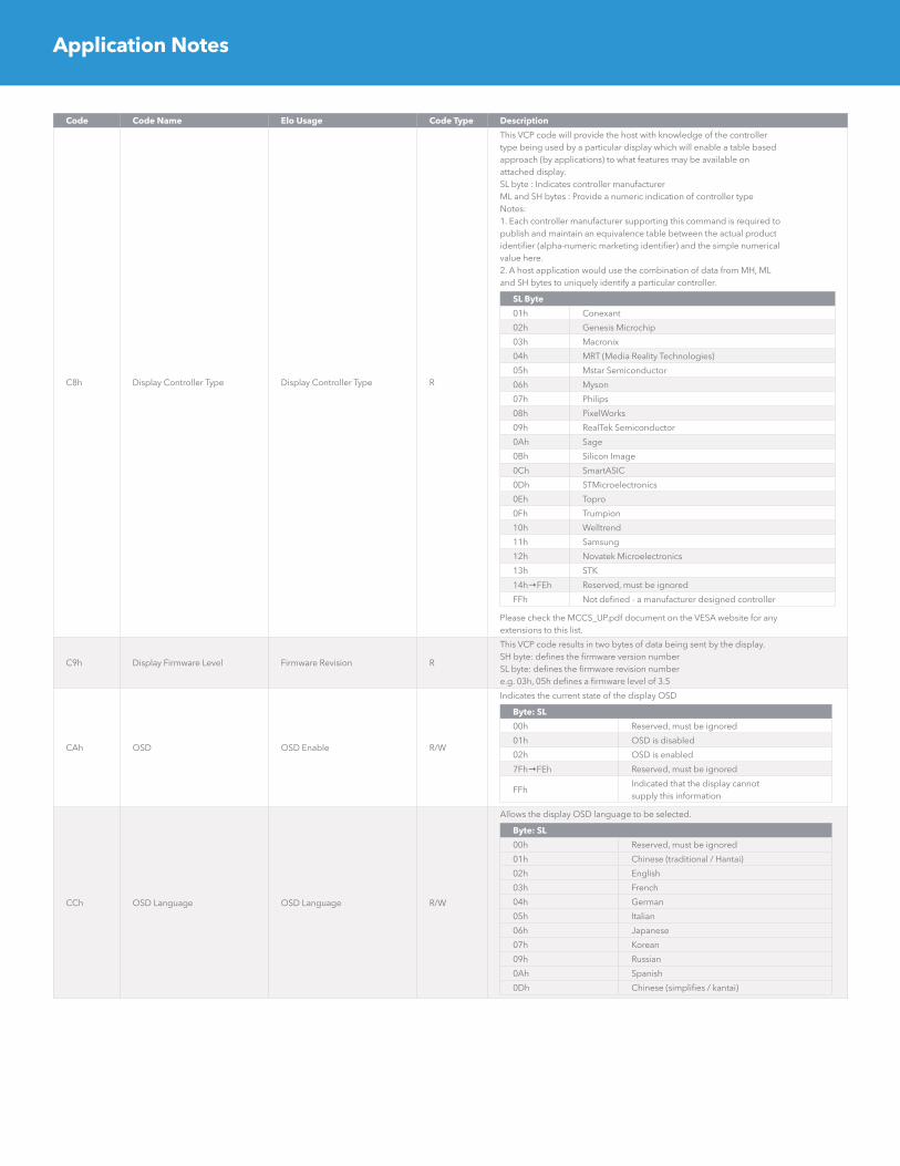
C8h Display Controller Type Display Controller Type R
This VCP code will provide the host with knowledge of the controllertype being used by a particular display which will enable a table basedapproach (by applications) to what features may be available onattached display.SL byte : Indicates controller manufacturerML and SH bytes : Provide a numeric indication of controller typeNotes:1. Each controller manufacturer supporting this command is required topublish and maintain an equivalence table between the actual productidentifier (alpha-numeric marketing identifier) and the simple numericalvalue here.2. A host application would use the combination of data from MH, MLand SH bytes to uniquely identify a particular controller.
SL Byte
01h Conexant
02h Genesis Microchip
03h Macronix
04h MRT (Media Reality Technologies)
05h Mstar Semiconductor
06h Myson
07h Philips
08h PixelWorks
09h RealTek Semiconductor
0Ah Sage
0Bh Silicon Image
0Ch SmartASIC
0Dh STMicroelectronics
0Eh Topro
0Fh Trumpion
10h Welltrend
11h Samsung
12h Novatek Microelectronics
13h STK
14h→FEh Reserved, must be ignored
FFh Not defined - a manufacturer designed controller
Please check the MCCS_UP.pdf document on the VESA website for anyextensions to this list.
C9h Display Firmware Level Firmware Revision R
This VCP code results in two bytes of data being sent by the display.SH byte: defines the firmware version numberSL byte: defines the firmware revision numbere.g. 03h, 05h defines a firmware level of 3.5
CAh OSD OSD Enable R/W
Indicates the current state of the display OSD
Byte: SL
00h Reserved, must be ignored
01h OSD is disabled
02h OSD is enabled
7Fh→FEh Reserved, must be ignored
FFhIndicated that the display cannotsupply this information
CCh OSD Language OSD Language R/W
Allows the display OSD language to be selected.
Byte: SL
00h Reserved, must be ignored
01h Chinese (traditional / Hantai)
02h English
03h French
04h German
05h Italian
06h Japanese
07h Korean
09h Russian
0Ah Spanish
0Dh Chinese (simplifies / kantai)
Application Notes
Code Code Name Elo Usage Code Type Description
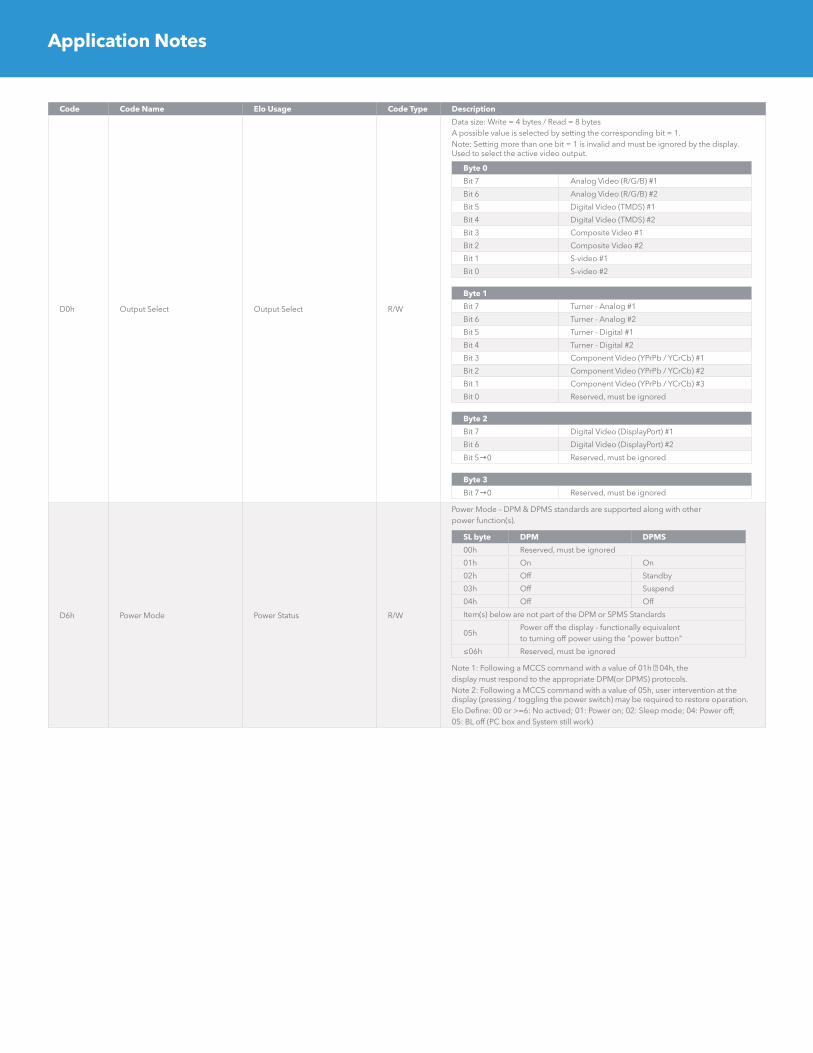
D0h Output Select Output Select R/W
Data size: Write = 4 bytes / Read = 8 bytesA possible value is selected by setting the corresponding bit = 1.Note: Setting more than one bit = 1 is invalid and must be ignored by the display. Used to select the active video output.
Byte 0
Bit 7 Analog Video (R/G/B) #1
Bit 6 Analog Video (R/G/B) #2
Bit 5 Digital Video (TMDS) #1
Bit 4 Digital Video (TMDS) #2
Bit 3 Composite Video #1
Bit 2 Composite Video #2
Bit 1 S-video #1
Bit 0 S-video #2
Byte 1
Bit 7 Turner - Analog #1
Bit 6 Turner - Analog #2
Bit 5 Turner - Digital #1
Bit 4 Turner - Digital #2
Bit 3 Component Video (YPrPb / YCrCb) #1
Bit 2 Component Video (YPrPb / YCrCb) #2
Bit 1 Component Video (YPrPb / YCrCb) #3
Bit 0 Reserved, must be ignored
Byte 2
Bit 7 Digital Video (DisplayPort) #1
Bit 6 Digital Video (DisplayPort) #2
Bit 5→0 Reserved, must be ignored
Byte 3
Bit 7→0 Reserved, must be ignored
D6h Power Mode Power Status R/W
Power Mode – DPM & DPMS standards are supported along with otherpower function(s).
SL byte DPM DPMS
00h Reserved, must be ignored
01h On On
02h Off Standby
03h Off Suspend
04h Off Off
Item(s) below are not part of the DPM or SPMS Standards
05hPower off the display - functionally equivalentto turning off power using the "power button"
≤06h Reserved, must be ignored
Note 1: Following a MCCS command with a value of 01h 04h, thedisplay must respond to the appropriate DPM(or DPMS) protocols.Note 2: Following a MCCS command with a value of 05h, user intervention at the display (pressing / toggling the power switch) may be required to restore operation.Elo Define: 00 or >=6: No actived; 01: Power on; 02: Sleep mode; 04: Power off; 05: BL off (PC box and System still work)
Application Notes

Code Code Name Elo Usage Code Type Description
DBh Image Mode Aspect to Ratio R/W
Controls aspects of the displayed image.Note: This VCP code is intended for use with TV applications.
Byte: SL Name Description
00h No effect
01h Full modeLinear expansion(compression) of theimage on horizontal axis
02h Zoome mode
Linear expansion(compression) of the image on horizontal and vertical axis
03h Squeeze mode
Display all of the imagecontent on visible screen.May result in unused areas a of visible screen... bars at top, bottom or sides.
04h Variable
Display all of the imagecontent by applyingnon-linear expansion(compression) to thehorizontal axis.
≥05h Reserved, must be ignored
Note: a more complete description of these modes may be found in the VESA DI-EXT standard.
DFh VCP Version VCP Version R
Defines the version number of the MCCS standard recognized by the display.SH byte: defines the MCCS version numberSL byte: defines the MCCS revision numbere.g. 03h 00h defines a MCCS level of 3.0 (this standard)Note: Support of this code is a mandatory requirement for compliance with MCCS standard Version 2 and higher.
EAh Alarm Alarm R
00: No alarm01: No support alarm sensor02: Temp over spec03: BL breakdown04: Fan stop
E3h Auto Color Auto Color W/R
01: Do Auto ColorReturn Result Value:Success :6E_51_E3_02_01_ChksumFailure: 6E_51_E3_03_01_Chksum
E5hSave Color TemperatureValue
Save Color TemperatureValue
W
E8h OSD Display on/off OSD Display W01: On00: Off
E6h Load Color Temperature ValueLoad Color TemperatureValue
W
F2h Factory Menu Factory Menu W
F3h Get Command Set Get Command Set R Get Command Set
F4hGet Monitor SN (1-4bytes)VCP String
Get Monitor SN (1-4bytes) RMH & ML : Serial Number 1 byte and 2 byteSH & SL : Serial Number 3 byte and 4 byte
F5hGet Monitor SN (5-8bytes)VCP String
Get Monitor SN (5-8bytes) RMH & ML : Serial Number 5 byte and 6 byteSH & SL : Serial Number 7 byte and 8 byte
F6hGet Monitor SN(9-10bytes) VCP String
Get Monitor SN(9-10bytes)
RMH & ML : Serial Number 9 byte and 10 byteSH & SL : 20h and 20h (ASCII Code: space)
F9h Sub Contrast Sub Contrast W
EC Panel Name Panel Name RMH ML :0x00 0xFFSH SL : 0x00 Panel ID
F0h Save Monitor SN Save Monitor SN W
Save Monitor Serial NumberWrite Monitor SN : 6E_51_8F_F0_Chr1_Chr2_Chr3_..._Chr13_Chr14_Checksum*The length of command depends on how long the SN is, the Maximumlength is 14.
E1h Get/Save Touch SN Get/Save Touch SN W/R
Get Touch Serial NumberSave:6E_51_8F_E1_Chr1_Chr2_Chr3_..._Chr14_Checksum + StopRead:// Get VCP: S_6E_51_82_01_(E1)_CHK_P// Reply: S_6F_6E_90_02_(E1)_Dat1_Dat2_Dat3_Dat4_Dat5_Dat6_Dat7_Dat8_Dat9_Dat10_ Dat11_Dat12_Dat13_Dat14_Chk*The length of command depends on how long the SN is, the Maximumlength is 14.
E2h Get Serial Number Get Serial Number R
Get Serial NumberRead:// Get VCP: S_6E_51_82_01_(E2)_CHK_P// Reply: S_6F_6E_90_02_(E2)_Dat1_Dat2_Dat3_Dat4_Dat5_Dat6_Dat7_Dat8_Dat9_Dat10_ Dat11_Dat12_Dat13_Dat14_Chk*The length of command depends on how long the SN is, the Maximumlength is 14.
Application Notes

Code Code Name Elo Usage Code Type Description
E9h Get/Save Monitor PN Get/Save Monitor PN W/R
Get Touch Serial NumberSave:6E_51_8F_E9_Chr1_Chr2_Chr3_..._Chr7_Checksum + StopRead:// Get VCP: S_6E_51_82_01_(E9)_CHK_P// Reply: S_6F_6E_89_02_(E9)_Dat1_Dat2_Dat3_Dat4_Dat5_Dat6_Dat7_Chk*The length of command depends on how long the SN is, the Maximumlength is 7.
EFh GPIO Control Control the GPIO W
Byte 1
Bit 7 Set GPIO1 as output
Bit 6 Set GPIO1 as input
Bit 5 Output GPIO1 as High level
Bit 4 Output GPIO1 as Low level
Bit 3 Start to do GPIO1 High to Low detection ( It will also clear High to Low records.)
Bit 2 Start to do GPIO1 Low to High detection ( It will also clear Low to High records.)
Bit 1 Reserve for other function.
Bit 0 Reserve for other function.
Byte 2
Bit 7 Set GPIO2 as output
Bit 6 Set GPIO2 as input
Bit 5 output GPIO2 as High level
Bit 4 output GPIO2 as Low level
Bit 3 Start to do GPIO2 High to Low detection ( It will also clear High to Low records.)
Bit 2 Start to do GPIO2 Low to High detection ( It will also clear Low to High records.)
Bit 1 Reserve for other function.
Bit 0 Reserve for other function.
GPIO1
Bit 15 Current GPIO1 has been set as output pin
Bit 14 Current GPIO1 has been set as input pin
Bit 13 GPIO1 current output pin status is High level
Bit 12 GPIO1 current output pin status is Low level
Bit 11 “High to Low” detecting function of GPIO1 is enabled
Bit 10 “High to Low” detecting function of GPIO1 is disabled
Bit 9 “Low to High” detecting function of GPIO1 is enabled
Bit 8 “Low to High” detecting function of GPIO1 is disabled
Bit 7 Bit7 – Bit4 : to read how many times , the “High to Low” status has ever happened on GPIO1.
Bit 6 ( Value range of record: Max.=15 , Min.=0 )
Bit 3 Bit3 – Bit0 : to read how many times , the “Low to High” status has ever happened on GPIO1.
Bit 2 ( Value range of record: Max.=15 , Min.=0 )
GPIO2
Bit 15 Current GPIO2 has been set as output pin
Bit 14 Current GPIO2 has been set as input pin
Bit 13 GPIO2 current output pin status is High level
Bit 12 GPIO2 current output pin status is Low level
Bit 11 “High to Low” detecting function of GPIO2 is enabled
Bit 10 “High to Low” detecting function of GPIO2 is disabled
Bit 9 “Low to High” detecting function of GPIO2 is enabled
Bit 8 “Low to High” detecting function of GPIO2 is disabled
Bit 7 Bit7 – Bit4 : to read how many times , the “High to Low” status has ever happened on GPIO2.
Bit 6 ( Value range of record: Max.=15 , Min.=0 )
Bit 3 Bit3 – Bit0 : to read how many times , the “Low to High” status has ever happened on GPIO2.
Bit 2 ( Value range of record: Max.=15 , Min.=0 )
Application Notes

Application Notes
To find out more about our extensive range of Elo touch solutions, go to elotouch.com, or call the office nearest you.
Elo reserves the right to change or update, without notice, any information contained herein; to change, without notice, the design, construction, materials, processing or specifications of any products; and to discontinue or limit production or distribution of any products. Elo, the Elo logo, are either trademarks or registered trademarks of Elo Touch Solutions, Inc. All other trademarks are the property of their respective owners. © 2017 Elo Touch Solutions, Inc. All rights reserved. 17084AEB00033
North America Tel +1 408 597 8000 Fax +1 408 597 8050 [email protected]
Europe Tel +32 (0)16 70 45 00 Fax +32 (0)16 70 45 49 [email protected]
Asia-Pacific Tel +86 (21) 3329 1385 Fax +86 (21) 3329 1400 www.elotouch.com.cn
Latin America Tel +52 55 2281-6958 [email protected]