elroy, wi 53929 - equipnet silo base instructions ... should your inspection reveal any damage or...
TRANSCRIPT

Copyright © 2007 Walker Stainless Equipment Company, LLC. This document contains confidential and proprietary information. Do not edit or reproduce without the permission of Walker Stainless Equipment Company, LLC
Page 1
Operation and Maintenance / Documentation Manual
Silo Storage Tank With Vertical Agitator Assembly
NIRO, INC. THE DANNON COMPANY, INC.
Walker Project Number – WEP-64435-RJA
Vessel Serial Number – WEP-64435 Customer P.O. Number – 09-701805 Tank designed to meet 3A standard Number 22-08
Date: 11/14/07
902 2nd Main Street Elroy, WI 53929

Copyright © 2007 Walker Stainless Equipment Company, LLC. This document contains confidential and proprietary information. Do not edit or reproduce without the permission of Walker Stainless Equipment Company, LLC
Page 2
Chapter 1 Introduction & Tank Arrival ....................................................................................................... 3
Walker Stainless Equipment..................................................................................................................... 3 Warranty Information..............................................................................................................................3-4 Contact Names.......................................................................................................................................... 5 Arrival Inspection ....................................................................................................................................... 6
Unloading................................................................................................................................................... 6 Unloading Detail Drawing - Wiith Alcove Factory Welded...................................................................... 7 Unloading Detail Drawing - Wiith Alcove Shipped Loose ....................................................................... 8
Anchoring silo tank………………………………………………………………………………………….9 Alternative Anchoring Design (Embed Plates)……………………………………………...…..……....10 Shiming Silo Base Instructions (If Applicable)..………………………………………………………… 11 Warning, Caution & Instruction Decals…………………………………….…………….……………….12 Initial Cleaning Procedures For Stainless Steel Equipment.................................................................. 12
Chapter 2 Cleaning & Components ...................................................................................................... 13 Manway Door .......................................................................................................................................... 13 Manway Detail Drawing .......................................................................................................................... 14
Sample Valve Detail Drawing ................................................................................................................. 15 C.I.P. Procedures .................................................................................................................................... 16
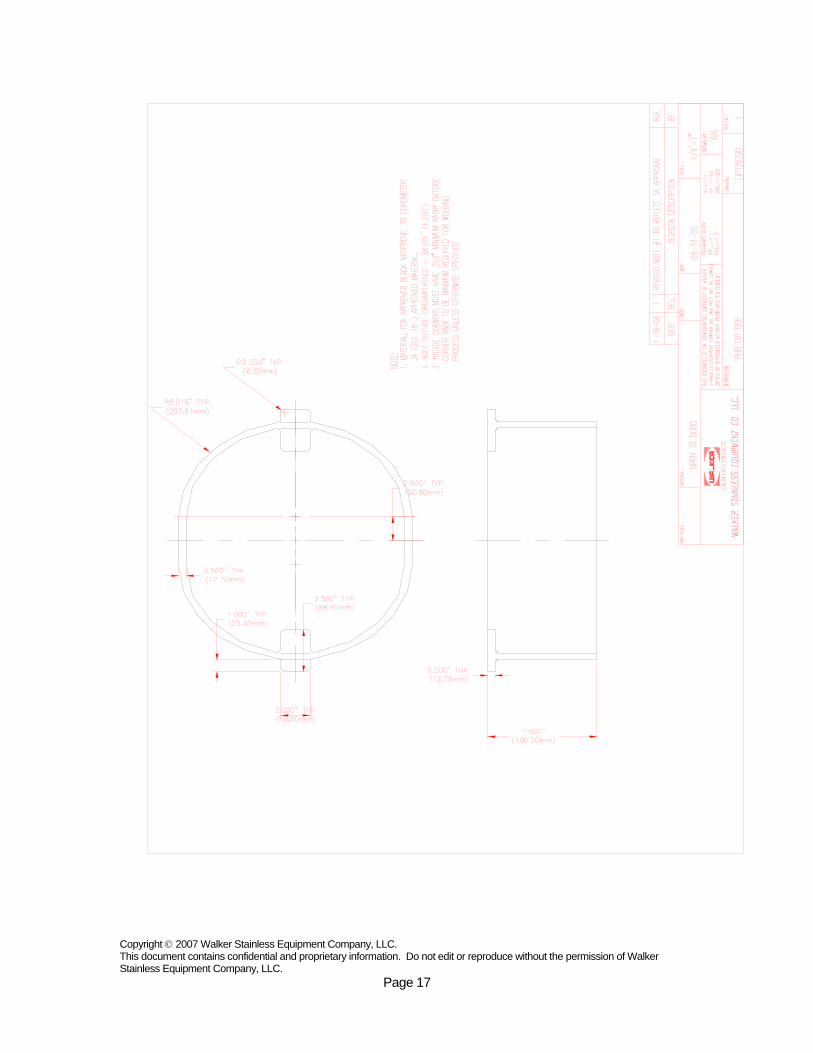
C.I.P. Door Detail Drawing....................................................................................................................... 17 Cleaning................................................................................................................................................... 18 Overfill Warning ....................................................................................................................................... 18 Installing Refrigeration On Coldwall Tanks ............................................................................................ 18 Vertical Agitator Instructions ................................................................................................................... 19 Walker Vertical Agitator Operation & Maintenance............................................................................... 20 Protecting Stainlesss Steel Dairy Equipment - "Life-Giving" Practices .........................................21-27 Heat Tape & Insulation On C.I.P. % Vent Lines (If Applicable) ............................................................ 28 Heat Tape Detail Drawing....................................................................................................................... 29
Chapter 3 Equipment Safety Recomendations ........................................................................................ 30 General Operating safety …………………………………………………………………………….30-31
Confined Space Safety ........................................................................................................................... 31 Pressurized System Safety - Heat Transfer Surface (If Applicable)..................................................... 32 Electrical Safety ..................................................................................................................................32-33 Service And Maintenance Safety ......................................................................................................33-34 Thermal Shock Loading.......................................................................................................................... 34
Chapter 4 General Information............................................................................................................... .35 Common Options .................................................................................................................................... 35 Additional Cleaning Recommendations................................................................................................. 36 Material Data Sheet: Stainless Steel 304 & 304L............................................................................37-40 Material Data Sheet: Stainless Steel 316 & 316L............................................................................41-44 ...................................................................................................................................................................... ……………………………………………………………………………………………………………………………………………………………………………………………………………………………………………………………………………………………………………………………………………………………………………………………………………………………………………………………………………………………………………………………………………………………………………………………

Copyright © 2007 Walker Stainless Equipment Company, LLC This document contains confidential and proprietary information. Do not edit or reproduce without the permission of Walker Stainless Equipment Company, LLC.
Page 3
Chapter 1 Introduction & General Information
Walker Stainless Equipment
Walker Stainless Equipment Company, LLC has been designing and fabricating standard and custom process and storage vessels for the food, beverage, dairy, personal care & pharmaceutical process industries for over six decades. We have worked with numerous companies to provide quality vessels for their processes.
Walker aspires to be the "best choice" for cost effective solutions and to "Meet or Exceed Customer’s Expectations with Quality Products". We are confident that you will feel we have accomplished our mission with this piece of equipment.
The following is the documentation manual for your vessel.
Warranty Information
Walker Stainless Equipment Company, LLC warrants new tanks or equipment manufactured by us to be free from defects in material and workmanship under normal use and service for a period of one (1) year after shipment from the factory. For breach of warranty of any kind, the measure of damages to be recoverable from Walker shall be limited to repair or replacement of the part or equipment which examination discloses to the satisfaction of Seller to be defective, or the payment of the price of making such repair or replacement, at the option of the Seller. This warranty is expressly in lieu of all other warranties, expressed or implied, and all other obligations and liabilities on our part. Any warranty of merchantability is expressly excluded. We neither assume nor authorize any other persons to assume for us any liability in connection with the sale of our products, and no other warranty will be honored unless in writing and signed by an officer of the corporation. This warranty shall not apply to any product of our manufacture which has been repaired or altered outside our factory, or which in our opinion, has been subject to misuse, negligence or accident. Seller will not assume any charges for repairs made during warranty by anyone other than Walker. Also Seller assumes no liability or responsibility for transportation, to and from repair point, nor any loss of time due to repair. This warranty does not cover components of other manufacturers beyond such warranty as is made by such manufacturer. Any such action for breach of warranty shall be commenced within one (1) year of said breach or be forever barred. All information including design details and dimensions contained herein are confidential and proprietary and must not be reproduced, disclosed to others, or used in the production of parts, unless authorized in writing by Walker.
Chapter
1

Copyright © 2007 Walker Stainless Equipment Company, LLC. This document contains confidential and proprietary information. Do not edit or reproduce without the permission of Walker Stainless Equipment Company, LLC
Page 4
Walker Stainless Equipment, LLC has great concern for possible difficulty in paper removal (if applicable), stains, difficulty in passivation, or, any other problems that may occur with materials / finish for tank sitting at our facility, in construction areas, or that have not been placed into service within a timely manner (within a month of fabrication completion date) and will not be held responsible for these issues as conditions are beyond our control.
Walker shall not be responsible for corrosion resistance of equipment or any resulting damages. It is Customer’s (Purchaser’s) responsibility to specify correct material of construction specifications for the intended application(s).
#2B Mill Finish Disclaimer - Light scratches, pits, and stains are common with 2B material finish. No claims will be accepted for light defects that would typically be removed with polish process.

Copyright © 2007 Walker Stainless Equipment Company, LLC This document contains confidential and proprietary information. Do not edit or reproduce without the permission of Walker Stainless Equipment Company, LLC.
Page 5
Contact Names
Project Manager Bob Anderson 902 2nd Main Street Elroy, WI 53929 Phone: (800) 356-5734 ext. 7901 Direct (608) 562-7901 Fax: (608) 562-7902 e-mail: [email protected]
---------------------------------- Sales Sharron Groskreutz 902 2nd Main Street Elroy, WI 53929 Phone: (800) 356-5734 ext. 7915 Direct (608) 562-7915 Fax: (608) 562-7916 e-mail: [email protected]
------------------------------------------ Spare Parts Bruce Ritchart 625 State Street New Lisbon, WI 53950 Phone: (608) 562-3151 Ext. 7585 Fax: (608) 562-7586 e-mail: [email protected]
--------------------------------- Field Service Coordinator Art Slater 625 State Street New Lisbon, WI 53950 Phone: (608) 562-3151 Ext. 7591 Fax: (608) 562-3178 Cell Phone: (608) 553-5863 e-mail: [email protected]

Copyright © 2007 Walker Stainless Equipment Company, LLC. This document contains confidential and proprietary information. Do not edit or reproduce without the permission of Walker Stainless Equipment Company, LLC
Page 6
ARRIVAL INSPECTION
The loading of your tank at the factory has been checked and inspected, but we cannot guarantee safe, undamaged and complete arrival to your destination. Please immediately check items against the Packing List to determine that parts and accessories as listed have been received in complete and satisfactory condition. Should your inspection reveal any damage or loss, notify the freight carrier and Walker Stainless “immediately”. Tank should be inspected for road salt, grease or dirt upon arrival and removed if present.
UNLOADING
Every precaution should be taken when unloading and installing your new Walker equipment. We suggest that you review the customer approved drawing or the copies provided with this manual with your riggers and or installers, before lifting and up-righting the vessel. Caution must be used when raising the tank from a horizontal to a vertical position. Damage could result if incorrect lifting procedures are followed. (See page 7 for factory welded alcove extension or page 8 for shipped loose alcove extension). Here are a few unloading and installation suggestions:
1. Furnish your rigger with pertinent information such as empty tank weight, and over all dimensions of the vessel so the correct moving equipment will be available.
2. The building wall should not place a load onto the alcove extension. We recommend the use of a soft gasket material or caulking next to the alcove sidewalls, and filling in the wall opening with masonry after setting the tank in place.
3. If the tank was ordered with support legs they need to be adjusted so that the vessel is level, and for equal weight distribution.
4. Avoid scratching of painted or stainless steel surfaces when lifting or moving. The use of padded cables or nylon slings is recommended to avoid such damage. Standard prime coat finishes on outer jacket should have finish paint applied as soon as possible (one week max).
5. Your new Walker Tank is equipped with a Vertical Agitator please remove any bracing, and protective coverings from the interior before up righting the vessel (see Manway Operating Instruction on page 12).

Copyright © 2007 Walker Stainless Equipment Company, LLC. This document contains confidential and proprietary information. Do not edit or reproduce without the permission of Walker Stainless Equipment Company, LLC.
Page 7

Copyright © 2007 Walker Stainless Equipment Company, LLC. This document contains confidential and proprietary information. Do not edit or reproduce without the permission of Walker Stainless Equipment Company, LLC.
Page 8

Copyright © 2007 Walker Stainless Equipment Company, LLC. This document contains confidential and proprietary information. Do not edit or reproduce without the permission of Walker Stainless Equipment Company, LLC.
Page 9
ANCHORING SILO TANK:
On Walker silo tanks furnished with hold down lugs / cover plates Walker furnishes a detail drawing (included with drawing approval packet) specifying recommended locations for anchor bolt size. These anchor bolts may be installed in the concrete pad prior to tank arrival or after the tank is set in place. For silos set in place prior to installing anchor bolts, use an epoxy to secure bolts in concrete. Follow details are provided on hold down detail drawing. When installing hold down lugs ~~ HOLD DOWN LUGS MUST NOT CONTACT CONCRETE PAD. Detail drawing indicates a ¼” distance from the bottom of the hold down lug and concrete pad.

Copyright © 2007 Walker Stainless Equipment Company, LLC. This document contains confidential and proprietary information. Do not edit or reproduce without the permission of Walker Stainless Equipment Company, LLC.
Page 10
Alternative anchoring design: For installations where a new concrete pad is to be constructed, Walker offers an alternate design. This design consists of embedded anchor plates installed in base when concrete is poured (embeds are furnish and installed by others). As with hold down lugs, Walker furnishes a detail drawing (included with drawing approval packet) specifying recommended locations for embed plates, size and number of bolts required per embed. The embed plates should be installed at or just below the top of the finished concrete pad. Note: Do not install embed plates above concrete pad.

Copyright © 2007 Walker Stainless Equipment Company, LLC. This document contains confidential and proprietary information. Do not edit or reproduce without the permission of Walker Stainless Equipment Company, LLC.
Page 11
A Walker silo tank is not perimeter supported. The support comes from the “Z” channel supports located under the silo bottom. These “Z” channels run from front to back of silo and are spaced according to tank size and weight requirements. NOTE: CONCRETE BASE MUST BE FLAT AND LEVEL WITHIN 1/8". IF BASE FLATNESS IS IN EXCESS OF THIS TOLERANCE, SHIMS WILL BE REQUIRED BETWEEN TANK SUPPORT BEAMS AND CONCRETE BASE. CHECK CONCRETE BASE FOR COMPLIANCE WITH FLATNESS TOLERANCE PRIOR TO TANK ERECTION. TANK BASE AND SUPPORT “Z” BEAMS HAVE BEEN INSPECTED PRIOR TO SHIPMENT TO INSURE THAT SUPPORT BEAM CONTACT SURFACES ARE WITHIN 1/8" OF PLANE OF SUPPORT. INSPECT TANK BASE PRIOR TO ACCEPTANCE FROM DELIVERING CARRIER TO INSURE THAT THEY HAVE NOT BEEN DAMAGED IN TRANSIT.

Copyright © 2007 Walker Stainless Equipment Company, LLC. This document contains confidential and proprietary information. Do not edit or reproduce without the permission of Walker Stainless Equipment Company, LLC.
Page 12
ALL WARNING, CAUTION, AND INSTRUCTION DECALS LOCATED ON SILO TANK
MUST BE ADHERED TO
INITIAL CLEANING PROCEDURES
FOR STAINLESS STEEL EQUIPMENT
When stainless steel processing vessels and storage equipment are shipped from the factory, a final cleaning is done to remove the manufacturing soils. No soluble oil is applied to the vessel surfaces.
During shipment and plant installation soils are deposited on both the external and internal surfaces, which must be removed before placing vessels into production. Remove all protective coverings (plastic, tape, etc.) that cover the Manway, Vent Screens, Fittings, etc. Then use both manual and CIP procedures for this cleaning, and inspect results. Frequently dullness of stainless steel surfaces is the result of shipping and installation soils. When combined with food soils, this can form a film which sometimes is difficult to remove, may become unsanitary, and could cause corrosion. It is advisable to passivate the vessel(s) after cleaning. Consult a competent chemical supplier for detailed cleaning recommendations and passivation procedure.

Copyright © 2007 Walker Stainless Equipment Company, LLC. This document contains confidential and proprietary information. Do not edit or reproduce without the permission of Walker Stainless Equipment Company, LLC.
Page 13
Chapter 2 Cleaning And Component Information
________________________________________________
MANWAY DOOR The Walker Elliptical Manway Door Assembly is opened by loosening the wingnut, and rotating the locking bar 90 degrees to the right (clockwise) to a horizontal position. Push the door inward, and invert the door so that the inside surface is facing upward and Sample Valve (if furnished) faces down and away from the opening. Carefully swing the door assembly through the opening to the outside, take care not to damage the gasket or the sealing face of the door ring. The “U” shaped Manway Gasket, Manway Door, and Sample Valve (if supplied) are to be manually cleaned. Install the Manway Door Assembly in reverse. Be certain that the Manway Door is centered in the ring with equal amounts of gasket shown in opening. Hand tightening of the Wingnut is all the pressure that is needed to ensure a proper seal. The closing instructions label is located above the door arm hinge for your reference. ***Note: Your Manway Door Assembly has been custom fit at the factory to ensure a proper seal, and is stamped with a serial number exclusive to your tank. You can find the number stamped on the Manway Door Center, Door Arm, and Door Ring. Please do not interchange these parts with other vessels because they are custom fit to ensure a proper seal. When installing the manhole gasket, stretch it over the door edge. Do not roll it on.
Chapter
2

Copyright © 2007 Walker Stainless Equipment Company, LLC. This document contains confidential and proprietary information. Do not edit or reproduce without the permission of Walker Stainless Equipment Company, LLC.
Page 14

Copyright © 2007 Walker Stainless Equipment Company, LLC. This document contains confidential and proprietary information. Do not edit or reproduce without the permission of Walker Stainless Equipment Company, LLC.
Page 15
Copyright © 2007 Walker Stainless Equipment Company, LLC. This document contains confidential and proprietary information. Do not edit or reproduce without the permission of Walker Stainless Equipment Company, LLC.
Page 16
PRECAUTIONS & INSTRUCTIONS FOR USING YOUR NEW WALKER STORAGE TANK
CIP PROCEDURES:
1. Refrigerated tanks having a pressure wall jacket (coldwall)
must have all liquid refrigerant removed from the pressure wall jacket prior to the application of hot pre-rinse or hot cleaning solutions. To protect against the possibility of excessive pressure deforming the coldwall surface, a #150 relief valve must be installed in the system. This is also to comply with the warranty by Walker on this equipment. The liquid refrigerant line must be closed and the compressor operating until all refrigerants has been removed from the coldwall jacket. When completely free of liquid refrigerant, there will be no cold spots on the inner surface, accumulator or connecting piping.
2. Open the Manway Door and swing it completely out of the tank per the Manway Instructions on page 13. This will allow for the large volume of heated air to escape during the cleaning cycles, and the large volume of air entering the tank during the cooling of the tank, thus preventing collapse and/or damage to the liner. Vent Lines alone are not adequate for proper venting during the CIP procedure- the Manway Door must be open. Hand clean the Manway Door, Door Gasket, and Sample Valve (if equipped).
3. Install the CIP Manway Door to conserve cleaning solutions. 4. Remove the Vent Screens in the Alcove and install the CIP
Interlock Manifold. It is designed to catch all CIP solutions from your vent line(s) and prevent any CIP operation without the Manway being open.
5. The tank is now ready for cleaning.
Copyright © 2007 Walker Stainless Equipment Company, LLC. This document contains confidential and proprietary information. Do not edit or reproduce without the permission of Walker Stainless Equipment Company, LLC.
Page 17

Copyright © 2007 Walker Stainless Equipment Company, LLC. This document contains confidential and proprietary information. Do not edit or reproduce without the permission of Walker Stainless Equipment Company, LLC.
Page 18
CLEANING: Please refer to the enclosed sheets covering cleaning of 18-8 Stainless Steel Storage and Transportation Tanks, Protecting Stainless steel Dairy Equipment From Corrosion (Life-Giving Practices).
////////////////////////////////////////////////////////////////////////////////////////////////////////////////////////////////
OVERFILLING: (Applies to Silo Type Storage Tanks)
This silo tank is designed for atmospheric pressure only. Do not expose silo tank to
internal pressure / vacuum. ***Do not overfill Silo Tank***.
Tank damage due to vacuum being created by overfilling will not be warranted.
//////////////////////////////////////////////////////////////////////////////////////////////////////////////////////////////// Installing Refrigeration on Coldwall Tanks:
The Coldwall Surface has been tested and the design working pressure is shown on the tank nameplate. The cooling surface is thoroughly blown out by air pressure and the openings sealed until the refrigeration connections are made. Always install liquid and suction line strainers with either Ammonia or Freon refrigerants. Always install a dehydrator equal to condensing unit capacity with Freon refrigerant. Install a pressure relief valve set at 150 P.S.I.G. in the suction line between the cooling jacket and the shut-off valve. This is necessary for both safety and to comply with Walker warranty.
Copyright © 2007 Walker Stainless Equipment Company, LLC. This document contains confidential and proprietary information. Do not edit or reproduce without the permission of Walker Stainless Equipment Company, LLC.
Page 19
Walker Vertical Agitator Initial Set up Procedure
(shipped loose)
1. The Agitator assembly and other parts are packed in the shipping box. Upon opening the box review the agitator drawing (provided) to identify the parts.
2. Locate the Agitator Shaft Seal and lubricate the “O” Ring seal with a food grade grease. Install with setscrews per the print provided in this booklet.
3. Locate the Shaft Coupling, and slide onto the Motor Output Shaft. Snug up the Set Screws to hold the coupling in place.
4. Install the (4) Mount Bolts into the Mount Plate, leaving them slightly loose. This will facilitate the installation of the Gearmotor. Set the Gearmotor onto the Mount Bolts and loosely install the lock washers and nuts. Tighten Mount Bolts first and then the nuts.
5. The Agitator Shaft with Impeller is located on the inside of the tank. Open the Manway Door per instruction on page 12. Remove all shipping materials (wood bracing, nylon strapping, tape, plastic, etc.). Attach the Agitator Shaft onto the Shaft Coupling by lifting the Shaft and turning to hook the Shaft Adapter to the Shaft Coupling per the drawing provided in this booklet. The bottom of the Shaft/Impeller must remain in the Bottom Guide Bearing during operation.
6. Install the Coupling Guard. 7. The breather plug for the Gearmotor is either already installed or packed in the conduit box on the
motor. For Eurodrive Gearmotors follow the instructions on Breather Plug Location. 8. Read the Operation and Maintenance Instructions carefully before operating!
Vertical Agitator Initial Set up Procedure
(installed) 1. The Agitator Assembly may be installed complete if your tank’s Vertical Agitator is a hollow bore
design (Note: refer to the drawing provided). Open the Manway Door per instruction on page 12. Remove all shipping materials (wood bracing, nylon strapping, tape, plastic, etc.). Verify guards are properly installed.
2. The breather plug for the Gearmotor is either already installed or packed in the conduit box on the
motor. For Eurodrive Gearmotors follow the instructions on Breather Plug Location. 3. Read the Operation and Maintenance Instructions carefully before operating!

Copyright © 2007 Walker Stainless Equipment Company, LLC. This document contains confidential and proprietary information. Do not edit or reproduce without the permission of Walker Stainless Equipment Company, LLC.
Page 20
Walker Vertical Agitator Operation & Maintenance
BEFORE OPERATING YOUR NEW WALKER VERT. AGITATOR: • Set-up your new Vertical Agitator according to the Initial
Setup Procedures (page 18) and the drawing provided. • Read these instructions completely and carefully. Call your
Walker Representative with any question you may have regarding setup and or operation.
DURING NORMAL TANK OPERATION: The Agitator Drive should not be operated when the product level is below the Agitator Impeller. Product level must always cover the lowest Impeller when operating. Operating the Agitator in low product condition could lead to whipping or foaming of the product. Starting the Agitator Drive when the product level is well above the lowest Impeller a Soft Start is recommended to prevent undue stress on the Gearmotor, Coupling (if provided), and Agitator Shaft. Note: However during CIP Operations the Agitator Drive should be running for proper cleaning of the Shaft/Impellers.
PERIODIC INSPECTION:
No equipment or procedures can replace the need for periodic inspection of cleanliness and sanitary conditions. Walker recommends this be done several times during the first few weeks of operation, and on a regular planned basis there-after.

Copyright © 2007 Walker Stainless Equipment Company, LLC. This document contains confidential and proprietary information. Do not edit or reproduce without the permission of Walker Stainless Equipment Company, LLC.
Page 21
PROTECTING STAINLESS STEEL DAIRY EQUIPMENT FROM CORROSION
Installation and Maintenance Cleaning and
“Life-Giving” Practices
Published by
NATIONAL ASSOCIATION OF DAIRY AND FOOD EQUIPMENT MANUFACTURERS
Washington, D.C.

Copyright © 2007 Walker Stainless Equipment Company, LLC. This document contains confidential and proprietary information. Do not edit or reproduce without the permission of Walker Stainless Equipment Company, LLC.
Page 22
Close observance of the practices and recommendations for installation, maintenance, cleaning, and bactericidal treatment of stainless steel equipment stated herein, will result in longer, corrosion-free life for your equipment and should provide a clean, sanitary surface for milk and milk products. Such practices and recommendations are consistent with the provisions of the United States Public Health Service Recommended Milk Ordinance.
NICKEL BEARING STAINLESS STEEL (AISI 300 Series) is resistant to corrosion by milk and other products, that is, under normal operation the milk and other dairy products that come in contact with the stainless steel will not cause corrosion. However, since the advent of circulation cleaning and C.I.P. procedures, corrosion problems in dairy plants have been aggravated. Nickel bearing stainless steel is the best material known to dairy equipment manufacturers for the construction of dairy equipment, but the following procedures must be followed in order to insure preservation of the surfaces of stainless steel equipment. INSTALLATION AND MAINTENANCE OF STAINLESS STEEL DAIRY EQUIPMENT Instructions: 1. The use of dissimilar metals should be minimized in the
fabrication of the product contact surfaces, especially if the equipment is to be placed in a C.I.P. type installation. Wherever possible, use only “AISI 300 Series” stainless steel. “WhiteMetal”, a copper-nickel alloy, should not be used in fabricating product contact surfaces. If possible, “AISI 400 Series” stainless steel should not be used with “AISI 300 series” in fabricating a product contact surface, especially if the equipment is to be used in a C.I.P. type installation.
2. Stainless steel tubing should be insulated from metal pipe hangers with non-absorbent insulation.
3. Gaskets should be non-absorbent materials that are free from iron oxide or other corrosive substances.

Copyright © 2007 Walker Stainless Equipment Company, LLC. This document contains confidential and proprietary information. Do not edit or reproduce without the permission of Walker Stainless Equipment Company, LLC.
Page 23
Reasons: 1. The use of dissimilar metals, even two different series stainless
steels, or “White Metal” for product contact surfaces in the same system may result in discoloration, pitting, or etching.
2. Failure to insulate may result in galvanic or other types of electrolytic corrosion with serious damage to the piping. Absorbent insulation may accumulate moisture and aid in the corrosion of the piping.
3. Chemically active gasketing material may induce corrosion.
Instructions: 4. Leaky gaskets and joints should be promptly replaced or
repaired. The use of different types of fittings in making pipe connections should be avoided, where possible. Properly designed and installed pipe and equipment supports and mountings are necessary to prevent undue mechanical strains and stresses on joints.
5. Welding and polishing should be performed by competent individuals using approved methods and materials. The use of low welding temperatures, appropriate grades of welding rod and parent metal, and iron free polishing wheels and compound is encouraged. Excessive grinding and polishing can leave the surface(s) in a weakened condition.
If any question exists as to the quality of the finished weld and polish, appropriate quality checks such as X-ray or dye-check should be used.
6. When new equipment, and particularly C.I.P. systems are installed, all electrical equipment in the area of the installation should be checked for proper connections, grounding, worn or damaged insulation, or other factors that might lead to stray electrical currents. Periodic “preventive maintenance” checks should be made to insure that this condition does not occur.
7. When installations is complete, and prior to use, the equipment and piping should be thoroughly cleaned, drained, and allowed to air dry, if possible. It should then be subjected to an approved bactericidal treatment just before product is to be processed.

Copyright © 2007 Walker Stainless Equipment Company, LLC. This document contains confidential and proprietary information. Do not edit or reproduce without the permission of Walker Stainless Equipment Company, LLC.
Page 24
Reasons: 4. Product and cleaning material leaking through joints may
promote corrosion if the corrosive material is allowed to remain in the joint area. C.I.P. Installations, where lines are not normally dismantled, are especially susceptible to corrosion in the joint area if leaks occur.
5. The corrosion resistance of even the highest grades of stainless steel may be reduced considerably by the use of excessive welding heat. By the use of low grade welding rod or parent metal; by the incorporation of iron particles during polishing; or from failure to remove weld spatter or fluxing agents.
Pits or voids remaining in the polished weld area should be completely removed since they form natural areas for corrosion to start.
6. A pitting form of corrosion may result if stray electrical current comes in contact with moist stainless steel. Local electrical power companies or electricians should be consulted with regard to detection of such a condition.
7. Thorough cleaning and air drying permits the formation of a protective oxide film, which is the key to placing the system in its most corrosion resistant (passive) condition.
CLEANING AND BACTERICIDAL TREATMENT
Instruction:
1. Use only products of reputable and responsible chemical
manufacturers who are familiar with dairy processing equipment processes and limitations, and who are able and willing to make specific recommendations for cleaning practices.
2. Use the manufacturer’s products in the precise manner in which they are recommended, but only with the concurrence of the equipment manufacturer.
3. Use a suitable water conditioner if the water supply is contaminated with foreign matter which may cause discoloration of the metallic surfaces or undesirable deposits.

Copyright © 2007 Walker Stainless Equipment Company, LLC. This document contains confidential and proprietary information. Do not edit or reproduce without the permission of Walker Stainless Equipment Company, LLC.
Page 25
4. When product processing has been completed, the heat transfer surface should be emptied (if included), and C.I.P. door immediately installed and then the equipment should be rinsed with warm water until the rinse water is clear. Complete circulation or manual cleaning should follow as soon as possible.
5. Use only soft non-metallic brushes, sponges, or pads, when manual cleaning is indicated. An extended period of soaking in the cleaning solution will facilitate removal of stubbornly adhering residues. Extreme care is required when manually brushing to avoid scratching the surface of stainless steel equipment.
Reasons: 1. Responsible chemical manufacturers continuously check the results
obtained with their products on dairy processing equipment, and maintain technically qualified staffs of service personnel.
2. Misuse of normally acceptable cleaning and bactericidal products, in excessive concentrations, temperatures, or exposure times, may cause permanent damage to processing equipment.
3. Deposits or discoloration from a contaminated water supply may counteract the best cleaning practices, and may cause corrosion of the best quality stainless steel equipment.
4. Product deposits are most easily removed while still moist, and considerable amounts of soil can be removed by the initial rinse following processing. Particles of moist soil left on the stainless surfaces may cause pitting at a point beneath the particle.
5. Metal brushes or sponges will scratch the surface of stainless steel equipment and may promote corrosion over an extended period of time. If improperly used, even non-metallic brushes may scratch the surface. Metallic particles from sponges, if allowed to remain on equipment or in pipelines, may cause corrosion.
Instructions: 6. If alkaline and acid cleaners are used alternately in circulation
cleaning, one must be completely rinsed out before the other is introduced into the system. After chemical circulation has been completed, the system must be thoroughly rinsed with warm water, then cool water, before it is shutdown. Whenever possible, the

Copyright © 2007 Walker Stainless Equipment Company, LLC. This document contains confidential and proprietary information. Do not edit or reproduce without the permission of Walker Stainless Equipment Company, LLC.
Page 26
system should be completely drained and opened to allow the metallic surfaces to air dry, so that the corrosion resisting passive film (oxide) may form.
7. Bactericidal treatment with “live steam” is many times only partially effective, and may cause considerable damage to processing equipment. It is not to be recommended.
8. When chemical bactericides are used, extreme caution must be exercised to use them only as prescribed by the chemical manufacturer, in concurrence with the local health authorities and the equipment manufacturer. Specific concentrations, temperatures, and exposure times must be followed as recommended. In addition, the chemical bactericide should be applied just before the equipment is to be used, and in no case should the exposure time exceed twenty (20) minutes.
9. If it is impossible to replace “White Metal” and “AISI 400 Series” stainless steel components from processing systems that are to be circulation cleaned, these parts should be removed from the system during the cleaning cycle and manually brushed, if at all possible.
Reason: 6. If alkaline cleaning solutions and milk residues are not completely
removed, a “milkstone” build-up may occur. If acid solutions are not completely removed, a highly corrosive atmosphere may form which can cause discoloration or pitting. In addition, most chemical bactericides are considerably more corrosive if they are introduced into an acidic medium. A thorough final rinse is of major importance in the prevention of corrosion.
7. Concentrated heat may cause buckling, erosion, or discolorations of stainless steel, and may reduce corrosion resistance in localized areas.
8. Excessive concentrations, exposure times, or temperatures employed during bactericidal treatment with chemicals may cause serious corrosion of the metal surface and premature aging of the sanitary rubber parts in the system. It should be noted that even a few degrees increase in the temperature at which the chemical bactericide is applied would greatly increase the chemical activity, and thus the corrosive effect upon the metallic surfaces and the aging effect upon the rubber

Copyright © 2007 Walker Stainless Equipment Company, LLC. This document contains confidential and proprietary information. Do not edit or reproduce without the permission of Walker Stainless Equipment Company, LLC.
Page 27
surfaces. Therefore, minimum temperatures should be employed when applying chemical bactericides.
9. “White Metal” and “AISI 400 Series” stainless steels are considerably less resistant to chemical attack than the “AISI 300 Series” stainless steel, and they may be readily corroded when cleaned by circulation methods.
/////////////////////////////////////////////////////////////////////////////////////////////////////////////////////////////////////////////////////////////////////////
“LIFE-GIVING” PRACTICES
1. Use only soft fiber brushes, pads, or sponges for manual cleaning. 2. Use a water conditioner if water is high in undesirable foreign
materials (Example, chlorine). 3. Remove weld spatter, fillings, fittings, wrenches, and rubber parts
from wet stainless steel surfaces. 4. Remove all milk residues from stainless steel surfaces. 5. Use chemical cleaners only as directed by the manufacturer, and
thoroughly rinse all alkaline and acid cleaners from stainless steel surfaces with clear water.
6. Apply chemical bactericides only as directed by manufacturer, and in
no case longer than twenty minutes prior to processing. 7. When possible, open equipment and allow to air dry after the final
clear water rinse. 8. Install equipment and piping so that all parts are aligned and well
supported to prevent undue stress or strain on any component. 9. Use only stainless steel of similar series in systems that are to be
cleaned by circulation methods. 10. Allow only qualified personnel, using approved techniques and
materials, to weld and polish stainless steel equipment.

Copyright © 2007 Walker Stainless Equipment Company, LLC. This document contains confidential and proprietary information. Do not edit or reproduce without the permission of Walker Stainless Equipment Company, LLC.
Page 28
Heat Tape & Insulation On C.I.P. And Vent Piping: If Applicable ~~ Silo tanks located in cold weather climate where temperatures drop to or below the freezing mark must be furnished with heat tape and insulation on the C.I.P. and vent piping to prevent lines from freezing. Condensation forming on the inside of the C.I.P. and vent line(s) may / will freeze thus restricting venting capability to the silo. Tank damage will occur once vent line(s) are restricted to the point they can no longer supply inside tank with enough air to compensate for product fill / empty rate thus causing tank damage due to pressure or vacuum. Standard Silo Tanks are designed for – Atmospheric Pressure

Copyright © 2007 Walker Stainless Equipment Company, LLC. This document contains confidential and proprietary information. Do not edit or reproduce without the permission of Walker Stainless Equipment Company, LLC.
Page 29

Copyright © 2007 Walker Stainless Equipment Company, LLC. This document contains confidential and proprietary information. Do not edit or reproduce without the permission of Walker Stainless Equipment Company, LLC.
Page 30
Chapter 3 Equipment Safety Recommendations
________________________________________________
Equipment Safety Recommendations
General Operating Safety • Do not operate this machine until you read and understand
the operating instructions and become thoroughly familiar with the machine and its controls.
• Never operate a machine while a safety device or guard is removed or disconnected.
• Always wear safety grasses, hats, shoes, ear protection or any other required safety equipment.
• Never remove “Warnings” that are displayed on the machine. Torn or worn labels should be replaced.
• Do not start the machine until all other personnel in the area have been warned and have moved outside the operating zone.
• Remove any tools or other foreign objects from the operating zone before starting.
• Absolutely do not have loose clothing, neckties, necklaces or unrestrained long hair near an operating machine.
• Do not wear gloves, rings, watches, bracelets or other jewelry near an operating machine.
• Keep the operating zone free of obstacles that could cause a person to trip or fall towards an operating machine.
• Never sit or stand on anything that might cause you to fall against the machine.
• ‘Horseplay” around a machine at any time is dangerous and prohibited.
Chapter
3
Copyright © 2007 Walker Stainless Equipment Company, LLC. This document contains confidential and proprietary information. Do not edit or reproduce without the permission of Walker Stainless Equipment Company, LLC.
Page 31
• Know the EMERGENCY STOP procedure for the machine.
• Air, hydraulic and electrical power must be off when the machine is not in use. Note: For maximum protection, the power source should be locked out using a lock for which only you have the key. This prevents anyone from accidentally turning on the power while you are servicing the machine.
• Never operate the machine above specified speeds, pressures or temperatures.
• Never manually operate limit switches with power on. • Keep alert and observe indicator lights and warnings that
are displayed on the machine. • Never leave the machine unattended while in operation. • Do not operate faulty or damaged equipment. Make certain
proper service and maintenance procedures have been performed.
• Avoid placing fingers, hands, or any part of your body into the machine or near moving parts when control circuits are energized.
• A safe work surface should be provided, including proper guarding of platform areas and the design and use of ladders.
SPECIAL NOTE - All installation, service, maintenance and operations must be performed in strict accordance with OSHA’s Standard for Control of Hazardous Energy (lockout/tagout) 29 CFR 1910.147.
Confined Space Safety
• Entering any area which meets the definition of a confined space may create a serious hazard for a worker.
• All maintenance and service procedures must be performed in strict accordance with OSHA standard #1910.146 (permit required confined space).

Copyright © 2007 Walker Stainless Equipment Company, LLC. This document contains confidential and proprietary information. Do not edit or reproduce without the permission of Walker Stainless Equipment Company, LLC.
Page 32
Pressurized System Safety –
HEAT TRANSFER SURFACE
(If Provided)
• Never operate a pressurized system unless covers, safety devices and indicators are operating and in place.
• Never operate a pressurized system above the pressure specified.
• Never loosen any fittings/connections when the system is under pressure.
• Never operate a machine that has leaks in the system. • A pressurized system can retain pressure even after the
power is off. Care is required to avoid injury.
Electrical Safety
• All electrical/electronic maintenance and service should be performed by trained and authorized electricians only.
• Always assume that power is on and treat all conditions as live. This practice assures a cautious approach which may prevent an accident or injury.
• To remove the load from circuit or equipment, open disconnect or breaker and lock in open position. Note: For maximum protection the power source should be locked out using a lock for which only you have the key. This prevents anyone from accidentally turning on the power while you are servicing the machine.
• Make certain that the circuit is open by using the proper test equipment. Note: Test equipment must be checked at regular intervals.
• Capacitors must be given time to discharge, otherwise it should be done manually with care.
• There may be circumstances where “trouble-shooting” on
live equipment may be required. Under such conditions, special precautions must be taken as follows:

Copyright © 2007 Walker Stainless Equipment Company, LLC. This document contains confidential and proprietary information. Do not edit or reproduce without the permission of Walker Stainless Equipment Company, LLC.
Page 33
Make certain your tools and body are clear of the ground
Extra safety measures should be taken in damp areas.
Be alert and avoid any outside distractions. • Before applying power to any equipment, make certain that
all personnel are clear of the machine. • Control panel doors should be open only when checking out
the electrical equipment or wiring. After closing the panel door, make certain that (on those panels where applicable) the disconnect handle mechanism is operating properly.
• All covers on junction panels should be closed before leaving any job.
• All electrical apparatus must be properly grounded and overload protected.
• All electrical connections should be protected by confining them within a sealed junction box.
Service and Maintenance Safety
• Do not service a machine until you are thoroughly qualified and familiar with the tasks to be performed.
• Never operate any controls while other persons are performing maintenance on the machine
• Do not bypass a safety device. • Always use the proper tool for the job. • Never open covers that house electrical components when
the power is on. • Only perform maintenance on a machine in motion when
properly trained and required to do so. When directed to make adjustments on machines in motion, extreme care must be taken.
• All air and hydraulic pressure must be relieved before performing maintenance or loosening connection on any pressurized system.

Copyright © 2007 Walker Stainless Equipment Company, LLC. This document contains confidential and proprietary information. Do not edit or reproduce without the permission of Walker Stainless Equipment Company, LLC.
Page 34
• Air, hydraulic and electrical powers are to be turned off unless they are absolutely required for the specific servicing being performed. Note: For maximum protection the power source should be locked out using a lock for which only you have the key. This prevents anyone from accidentally turning on the power while you are servicing the machine.
• Replace fuses only when electrical power is off (locked out). • Do not enter a confined space without first checking for toxic
fumes and providing standby personnel on the site.
Thermal Shock Loading Direct expansion of stainless steel is approximately 9.6x10⁻⁶ inches/inch/temperature differential. This rapid expansion rate, if not controlled, will be detrimental to the weld or material integrity of the vessel and may cause shock loading with results of eventual metal fatigue.
Shock loading is very easy to detect. Especially when the tank begins to make rapid expansion noises (crackling, popping, or hammering sounds). In a heat exchange system these sounds can also occur if air, etc… is not purged before use.
To prevent Shock Loading, whether it be a heat exchange surface or a tank, we recommend not exceeding a 50 F temperature differential when cooling, heating, or cleaning (CIP).
It has been noted, when cooling, that some manufacturers will use tempered solutions while others will allow time for the tank to cool by itself. Both procedures are effective for prevention of shock loading.
A gradual rise or reduction in metal temperature will afford maximum longevity of material.

Copyright © 2007 Walker Stainless Equipment Company, LLC. This document contains confidential and proprietary information. Do not edit or reproduce without the permission of Walker Stainless Equipment Company, LLC.
Page 35
Chapter 4 General Information
________________________________________________
Common Options. 1) If your tank is equipped with heat transfer surface, a relief valve
(typically NOT supplied by Walker) must be installed on the inlet with a rating not greater than the jacket rating on the nameplate. The sizing of this valve must include consideration for over pressurization by thermal expansion and/or any mechanical means possible in the system in which the heat transfer surface is installed. If this vessel is refrigerated by direct expansion, DO NOT use water at temperatures higher than 115 Deg. F. because of danger of developing high refrigerant pressures.
2) If your tank is equipped with C.I.P. sprayballs, caution must be used
when introducing hot cleaning solution into a cold tank. There is potential for vacuum damage to the tank (manway door must be open during C.I.P.. operation) and pressure damage to the cooling surface.
3) If your tank is equipped with insulation and sheathing, a weep hole with a plastic plug has been provided in the tank bottom to allow the insulated area to breathe. This vent should be checked periodically to make sure that it is clean and free of debris. If you notice product or water flowing from this vent plug, call the factory as soon as possible.
Chapter
4

Copyright © 2007 Walker Stainless Equipment Company, LLC. This document contains confidential and proprietary information. Do not edit or reproduce without the permission of Walker Stainless Equipment Company, LLC
Page 36
Additional Cleaning Recommendations
Things To Do Things Not To Do
Contact a competent chemical supplier for detailed cleaning recommendations and
passivation procedure**
Remove any placards, labels or other identification markings.
Refer to manufacturer’s information for the proper use, care and maintenance of all
components.
Wear rings, jewelry or other sharp objects when entering the vessel.
Wear appropriate personal protective equipment for the environment in which you are
working.
Use abrasive cleaners on viewing windows or panels.
Use proper safety precautions (as recommended by the manufacturer) when handling sanitization or cleaning agents.
Use steel wool as particles may become imbedded in the surface and develop rust.
Use water high in iron, salt, or sulphur
Allow foreign matter to adhere to tank
Allow rubber or metal parts, wrenches, or fittings to rest on wet stainless steel surfaces as
this excludes air and prevents drying
Allow bactericides or cleaners to remain on surfaces for over 20 minutes
Use chemical bactericides or cleaners in excess of manufacturer’s instructions as it wastes material and may cause corrosion
Apply pressure in tank unless designed for such services
Use chlorinated solvents on stainless steel surfaces.
** Walker Stainless Equipment highly recommends an onsite passivation prior to placing equipment into service.

Copyright © 2007 Walker Stainless Equipment Company, LLC. This document contains confidential and proprietary information. Do not edit or reproduce without the permission of Walker Stainless Equipment Company, LLC.
Page 37
Material Data Sheet: Stainless Steel 304 and 304L
Chemical Formula Fe, <0.8% C, 17.5-20% Cr, 8-11% Ni, <2% Mn, <1% Si, <0.045% P, <0.03% S Background Grade 304 is the standard "18/8" stainless; it is the most versatile and most widely used stainless steel, available in a wider range of products, forms and finishes than any other. It has excellent forming and welding characteristics. The balanced austenitic structure of Grade 304 enables it to be severely deep drawn without intermediate annealing, which has made this grade dominant in the manufacture of drawn stainless parts such as sinks, hollow-ware and saucepans. For these applications it is common to use special "304DDQ" (Deep Drawing Quality) variants. Grade 304 is readily brake or roll formed into a variety of components for applications in the industrial, architectural, and transportation fields. Grade 304 also has outstanding welding characteristics. Post-weld annealing is not required when welding thin sections. Grade 304L, the low carbon version of 304, does not require post-weld annealing and so is extensively used in heavy gauge components (over about 6mm). Grade 304H with its higher carbon content finds application at elevated temperatures. The austenitic structure also gives these grades excellent toughness, even down to cryogenic temperatures. Key Properties These properties are specified for flat rolled product (plate, sheet and coil) in ASTM A240/A240M. Similar but not necessarily identical properties are specified for other products such as pipe and bar in their respective specifications. Composition Typical compositional ranges for grade 304 stainless steels are given in table 1.
Table 1. Composition ranges for 304 grade stainless steel
Grade C Mn Si P S Cr Mo Ni N
304 min.
max.
-
0.08
-
2.0
-
0.75
-
0.045
-
0.030
18.0
20.0 -
8.0
10.5
-
0.10
304L min.
max.
-
0.030
-
2.0
-
0.75
-
0.045
-
0.030
18.0
20.0 -
8.0
12.0
-
0.10
304H min.
max.
0.04
0.10
-
2.0
-
0.75
-
0.045
-
0.030
18.0
20.0 -
8.0
10.5 -

Copyright © 2007 Walker Stainless Equipment Company, LLC. This document contains confidential and proprietary information. Do not edit or reproduce without the permission of Walker Stainless Equipment Company, LLC.
Page 38
Mechanical Properties Typical mechanical properties for grade 304 stainless steels are given in table 2.
Table 2. Mechanical properties of 304 grade stainless steel
Hardness
Grade Tensile
Strength (MPa) min
Yield Strength 0.2% Proof (MPa) min
Elongation (% in 50mm) min Rockwell
B (HR B) max
Brinell (HB) max
304 515 205 40 92 201
304L 485 170 40 92 201
304H 515 205 40 92 201
304H also has a requirement for a grain size of ASTM No 7 or coarser.
Physical Properties Typical physical properties for annealed grade 304 stainless steels are given in table 3.
Table 3. Physical properties of 304 grade stainless steel in the annealed condition
Mean Coefficient of Thermal Expansion (μm/m/°C)
Thermal Conductivity
(W/m.K) Grade
Density (kg/m3)
Elastic Modulus
(GPa) 0-100°C
0-315°C
0-538°C at
100°C at
500°C
Specific Heat 0-100°C
(J/kg.K)
Electrical Resistivity
(nΩ.m)
304/L/H 8000 193 17.2 17.8 18.4 16.2 21.5 500 720
Grade Specification Comparison Approximate grade comparisons for 304 stainless steels are given in table 4.
Table 4. Grade specifications for 304 grade stainless steel
Old British Euronorm Grade UNS No
BS En No Name
Swedish SS
Japanese JIS
304 S30400 304S31 58E 1.4301 X5CrNi18-10 2332 SUS 304
304L S30403 304S11 - 1.4306 X2CrNi19-11 2352 SUS 304L
304H S30409 304S51 - 1.4948 X6CrNi18-11 - -
These comparisons are approximate only. The list is intended as a comparison of functionally similar materials not as a schedule of contractual equivalents. If exact equivalents are needed original specifications must be consulted.

Copyright © 2007 Walker Stainless Equipment Company, LLC. This document contains confidential and proprietary information. Do not edit or reproduce without the permission of Walker Stainless Equipment Company, LLC.
Page 39
Possible Alternative Grades Possible alternative grades to grade 304 stainless steels are given in table 5.
Table 5. Possible alternative grades to 304 grade stainless steel
Grade Why it might be chosen instead of 304
301L A higher work hardening rate grade is required for certain roll formed or stretch formed components.
302HQ Lower work hardening rate is needed for cold forging of screws, bolts and rivets.
303 Higher machinability needed, and the lower corrosion resistance, formability and weldability are acceptable.
316 Higher resistance to pitting and crevice corrosion is required, in chloride environments
321 Better resistance to temperatures of around 600-900°C is needed…321 has higher hot strength.
3CR12 A lower cost is required, and the reduced corrosion resistance and resulting discolouration are acceptable.
430 A lower cost is required, and the reduced corrosion resistance and fabrication characteristics are acceptable.
Corrosion Resistance Excellent in a wide range of atmospheric environments and many corrosive media. Subject to pitting and crevice corrosion in warm chloride environments, and to stress corrosion cracking above about 60°C. Considered resistant to potable water with up to about 200mg/L chlorides at ambient temperatures, reducing to about 150mg/L at 60°C.
Heat Resistance Good oxidation resistance in intermittent service to 870°C and in continuous service to 925°C. Continuous use of 304 in the 425-860°C range is not recommended if subsequent aqueous corrosion resistance is important. Grade 304L is more resistant to carbide precipitation and can be heated into the above temperature range.
Grade 304H has higher strength at elevated temperatures so is often used for structural and pressure-containing applications at temperatures above about 500°C and up to about 800°C. 304H will become sensitised in the temperature range of 425-860°C; this is not a problem for high temperature applications, but will result in reduced aqueous corrosion resistance.
Heat Treatment Solution Treatment (Annealing) - Heat to 1010-1120°C and cool rapidly. These grades cannot be hardened by thermal treatment.

Copyright © 2007 Walker Stainless Equipment Company, LLC. This document contains confidential and proprietary information. Do not edit or reproduce without the permission of Walker Stainless Equipment Company, LLC.
Page 40
Welding Excellent weldability by all standard fusion methods, both with and without filler metals. AS 1554.6 pre-qualifies welding of 304 with Grade 308 and 304L with 308L rods or electrodes (and with their high silicon equivalents). Heavy welded sections in Grade 304 may require post-weld annealing for maximum corrosion resistance. This is not required for Grade 304L. Grade 321 may also be used as an alternative to 304 if heavy section welding is required and post-weld heat treatment is not possible.
Machining A "Ugima" improved machinability version of grade 304 is available in bar products. "Ugima" machines significantly better than standard 304 or 304L, giving higher machining rates and lower tool wear in many operations.
Dual Certification It is common for 304 and 304L to be stocked in "Dual Certified" form, particularly in plate and pipe. These items have chemical and mechanical properties complying with both 304 and 304L specifications. Such dual certified product does not meet 304H specifications and may be unacceptable for high temperature applications
Applications • Food processing equipment, particularly in beer brewing, milk processing & wine making. • Kitchen benches, sinks, troughs, equipment and appliances • Architectural panelling, railings & trim • Chemical containers, including for transport • Heat Exchangers • Woven or welded screens for mining, quarrying & water filtration • Threaded fasteners • Springs Source: Atlas Steels Australia
Copyright © 2007 Walker Stainless Equipment Company, LLC. This document contains confidential and proprietary information. Do not edit or reproduce without the permission of Walker Stainless Equipment Company, LLC.
Page 41
Material Data Sheet: Stainless Steel 316 and 316L
Chemical Formula Fe, <0.03% C, 16-18.5% Cr, 10-14% Ni, 2-3% Mo, <2% Mn, <1% Si, <0.045% P, <0.03% S Background
Grade 316 is the standard molybdenum-bearing grade, second in importance to 304 amongst the austenitic stainless steels. The molybdenum gives 316 better overall corrosion resistant properties than Grade 304, particularly higher resistance to pitting and crevice corrosion in chloride environments. It has excellent forming and welding characteristics. It is readily brake or roll formed into a variety of parts for applications in the industrial, architectural, and transportation fields. Grade 316 also has outstanding welding characteristics. Post-weld annealing is not required when welding thin sections.
Grade 316L, the low carbon version of 316 and is immune from sensitisation (grain boundary carbide precipitation). Thus it is extensively used in heavy gauge welded components (over about 6mm). Grade 316H, with its higher carbon content has application at elevated temperatures, as does stabilised grade 316Ti.
The austenitic structure also gives these grades excellent toughness, even down to cryogenic temperatures.
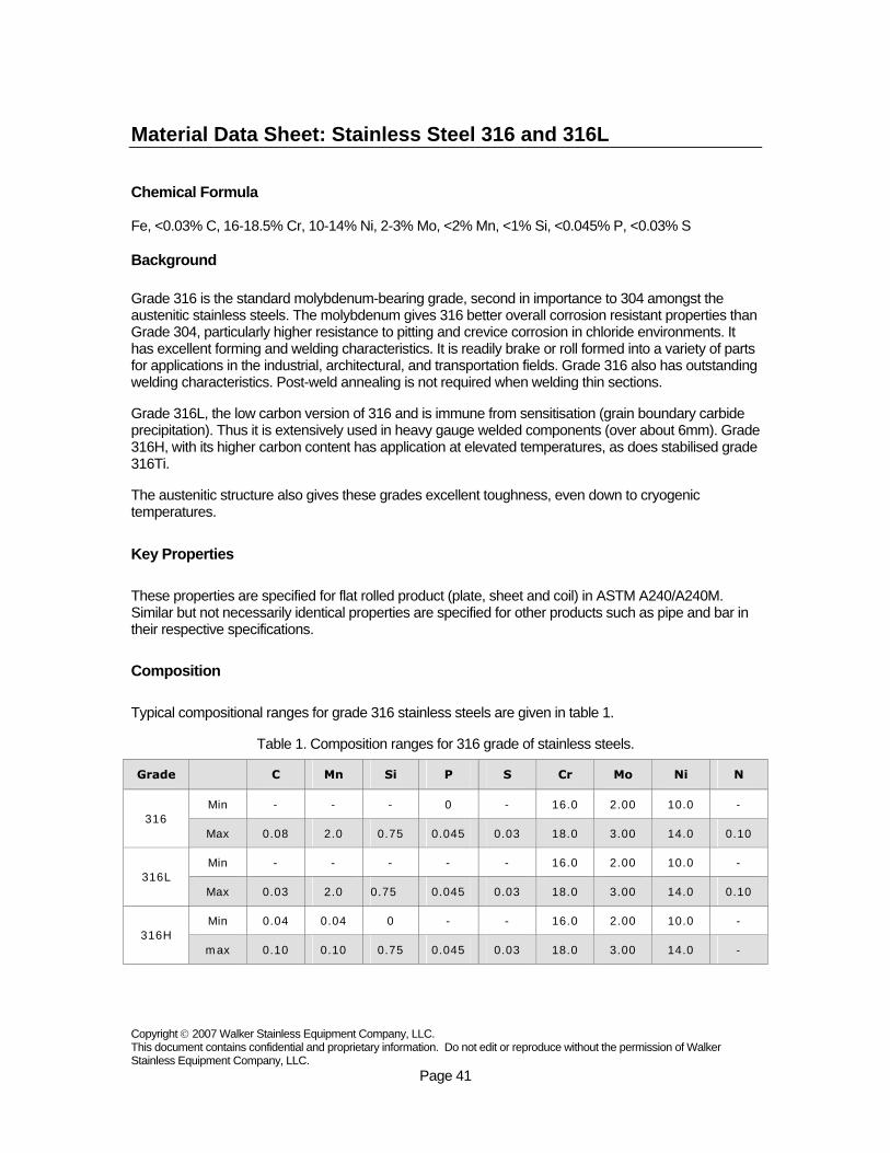
Key Properties These properties are specified for flat rolled product (plate, sheet and coil) in ASTM A240/A240M. Similar but not necessarily identical properties are specified for other products such as pipe and bar in their respective specifications. Composition Typical compositional ranges for grade 316 stainless steels are given in table 1.
Table 1. Composition ranges for 316 grade of stainless steels.
Grade C Mn Si P S Cr Mo Ni N
Min - - - 0 - 16.0 2.00 10.0 - 316
Max 0.08 2.0 0.75 0.045 0.03 18.0 3.00 14.0 0.10
Min - - - - - 16.0 2.00 10.0 - 316L
Max 0.03 2.0 0.75 0.045 0.03 18.0 3.00 14.0 0.10
Min 0.04 0.04 0 - - 16.0 2.00 10.0 - 316H
max 0.10 0.10 0.75 0.045 0.03 18.0 3.00 14.0 -

Copyright © 2007 Walker Stainless Equipment Company, LLC. This document contains confidential and proprietary information. Do not edit or reproduce without the permission of Walker Stainless Equipment Company, LLC.
Page 42
Mechanical Properties Typical mechanical properties for grade 316 stainless steels are given in table 2.
Table 2. Mechanical properties of 316 grade stainless steels.
Hardness
Grade Tensile Str (MPa) min
Yield Str 0.2% Proof (MPa) min
Elong (% in 50mm)
min Rockwell B (HR B) max
Brinell (HB) max
316 515 205 40 95 217
316L 485 170 40 95 217
316H 515 205 40 95 217
Note: 316H also has a requirement for a grain size of ASTM no. 7 or coarser. Physical Properties Typical physical properties for annealed grade 316 stainless steels are given in table 3.
Table 3. Typical physical properties for 316 grade stainless steels.
Mean Co-eff of Thermal Expansion (µm/m/°C)
Thermal Conductivity
(W/m.K) Grade
Density (kg/m3)
Elastic Modulus
(GPa) 0-
100°C 0-
315°C 0-
538°C At
100°C At
500°C
Specific Heat 0-100°C
(J/kg.K)
Elec Resistivity
(nΩ.m)
316/L/H 8000 193 15.9 16.2 17.5 16.3 21.5 500 740
Grade Specification Comparison Approximate grade comparisons for 316 stainless steels are given in table 4.
Table 4. Grade specifications for 316 grade stainless steels.
Old British Euronorm Grade
UNS No
BS En No Name
Swedish SS
Japanese JIS
316 S31600 316S31 58H, 58J 1.4401 X5CrNiMo17-12-2 2347 SUS 316
316L S31603 316S11 - 1.4404 X2CrNiMo17-12-2 2348 SUS 316L
316H S31609 316S51 - - - - -
Note: These comparisons are approximate only. The list is intended as a comparison of functionally similar materials not as a schedule of contractual equivalents. If exact equivalents are needed original specifications must be consulted.

Copyright © 2007 Walker Stainless Equipment Company, LLC. This document contains confidential and proprietary information. Do not edit or reproduce without the permission of Walker Stainless Equipment Company, LLC.
Page 43
Possible Alternative Grades Possible alternative grades to grade 304 stainless steels are given in table 5.
Table 5. Possible alternative grades to 316 stainless steel.
Grade Why it might be chosen instead of 316?
316Ti Better resistance to temperatures of around 600-900°C is needed.
316N Higher strength than standard 316.
317L Higher resistance to chlorides than 316L, but with similar resistance to stress corrosion cracking.
904L Much higher resistance to chlorides at elevated temperatures, with good formability
2205 Much higher resistance to chlorides at elevated temperatures, and higher strength than 316
Corrosion Resistance Excellent in a range of atmospheric environments and many corrosive media - generally more resistant than 304. Subject to pitting and crevice corrosion in warm chloride environments, and to stress corrosion cracking above about 60°C. Considered resistant to potable water with up to about 1000mg/L chlorides at ambient temperatures, reducing to about 500mg/L at 60°C.
316 is usually regarded as the standard “marine grade stainless steel”, but it is not resistant to warm sea water. In many marine environments 316 does exhibit surface corrosion, usually visible as brown staining. This is particularly associated with crevices and rough surface finish.
Heat Resistance
Good oxidation resistance in intermittent service to 870°C and in continuous service to 925°C. Continuous use of 316 in the 425-860°C range is not recommended if subsequent aqueous corrosion resistance is important. Grade 316L is more resistant to carbide precipitation and can be used in the above temperature range. Grade 316H has higher strength at elevated temperatures and is sometimes used for structural and pressure-containing applications at temperatures above about 500°C.
Heat Treatment Solution Treatment (Annealing) - Heat to 1010-1120°C and cool rapidly. These grades cannot be hardened by thermal treatment.
Welding Excellent weldability by all standard fusion methods, both with and without filler metals. AS 1554.6 pre-qualifies welding of 316 with Grade 316 and 316L with Grade 316L rods or electrodes (or their high silicon equivalents). Heavy welded sections in Grade 316 require post-weld annealing for maximum corrosion resistance. This is not required for 316L. Grade 316Ti may also be used as an alternative to 316 for heavy section welding.

Copyright © 2007 Walker Stainless Equipment Company, LLC. This document contains confidential and proprietary information. Do not edit or reproduce without the permission of Walker Stainless Equipment Company, LLC.
Page 44
Machining A “Ugima” improved machinability version of grade 316 is available in round and hollow bar products. This machines significantly better than standard 316 or 316L, giving higher machining rates and lower tool wear in many operations.
Dual Certification It is common for 316 and 316L to be stocked in "Dual Certified" form - mainly in plate and pipe. These items have chemical and mechanical properties complying with both 316 and 316L specifications. Such dual certified product does not meet 316H specification and may be unacceptable for high temperature applications.
Applications • Food preparation equipment particularly in chloride environments. • Laboratory benches & equipment. • Coastal architectural panelling, railings & trim. • Boat fittings. • Chemical containers, including for transport. • Heat Exchangers. • Woven or welded screens for mining, quarrying & water filtration. • Threaded fasteners. • Springs. Source: Atlas Steels Australia