em propagation in jet engine turbines - syntonics€¦ · · 2013-11-09em propagation in jet...
TRANSCRIPT

EM PROPAGATION IN JET ENGINE TURBINES
Eric Walton, Jonathan Young, Jim Moore and Kyle Davis
The Ohio State University ElectroScience Laboratory614 292 5051 [email protected]
AbstractThere is interest in the propagation of EM
signals inside jet engine turbines for a number ofreasons. Applications include radar scatteringphenomenology and jet engine plasma plumeformation studies. In our research, we are interestedin the communication channel characteristics formicro-size wireless sensors attached to the turbineblades that measure parameters such as strain andtemperature.
Propagation measurements were performed onboth F-16 (F-110) and Boeing 747 (CF6-50) turbines.The frequency band extended from 2 to 20 GHz(wavelengths longer than the turbine blades towavelengths shorter than the gap between turbineblades). Signals were propagated with both radialand circumferential polarization. Both transmissionand scattering measurements were made from boththe inlet and the outlet. We also used small probeantennas inserted in boreholes between turbinestages. A range of blade positions were included.
We will show the propagation characteristics as afunction of polarization, frequency and time (UWBtime domain transformations). We will also show theinternal radar reflection characteristics of the turbineas a function of various stator blade rotation angles.Comparisons with a hybrid mathematicalpropagation model will be given.
Keywords: Turbine, RF Propagation, EMMeasurements
1. Introduction
As part of a wireless strain gage project, a series ofexperimental measurements were made of propagation inreal full-scale jet engine turbines. Propagation in engineturbines previously has considered the turbine as an openended cavity [1, 2, and 3]. This model does not includethe complex stator and rotor blade distribution and thenon-uniform cross section of the air passage as the air iscompressed from stage to stage. In this study, thesetheoretical limitations are overcome by a directexperimental measurement program. Experimental
transmission measurements were made from the inlet tothe outlet, from the outlet to the inlet, and from theoutlet to several inspection boreholes in the engines.Reflection measurements were also made, and reflectionsfrom the various stages of the turbine can be identified inthe time domain plots of the data.
We also created a simplified model of the internalpropagation in order to understand the multipathenvironment. Parameters from the experimentalmeasurements can be used to set the parameters of thescattering model.
We will show the measurement data in both thefrequency domain and the time domain. We will showthe model, and comparisons between the model resultsand the measurement results. Overall propagationcharacteristics will be summarized.
2. Experimental Setup
Both a small turbine (F110-GE-100; F16) and a largeturbine (GE CF6-50; Boeing 747) were tested. Figure 1shows a cut-away diagram of the large turbine (typical ofJet engine turbines). Air flows into the large blade (fan)section, where some air is diverted in a bypass chamberoutside of the working air. The compressor section(between the inner shaft and the outer compressor wall)is the region of RF propagation of interest here. Air iscompressed in stages between stator (non-rotating) bladesand rotor blades. The size of the air gaps (and thus ofthe RF propagation duct) decreases from the inlet to thefinal compressor stage.
Propagation was measured by using a network analyzerand UWB ridge waveguide horn antennas (2-12 GHz).Identical antennas were used to transmit and receive thesignal, or a small conical monopole was inserted into theboreholes as a receive antenna. Scattering measurements(S11) were also made.
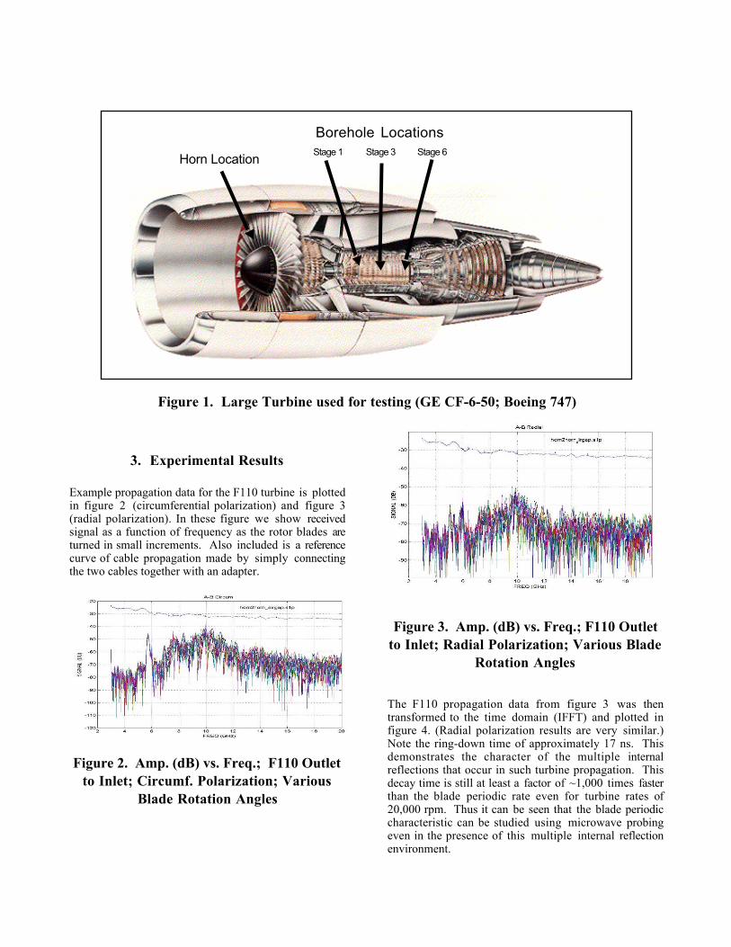
Figure 1. Large Turbine used for testing (GE CF-6-50; Boeing 747)
3. Experimental Results
Example propagation data for the F110 turbine is plottedin figure 2 (circumferential polarization) and figure 3(radial polarization). In these figure we show receivedsignal as a function of frequency as the rotor blades areturned in small increments. Also included is a referencecurve of cable propagation made by simply connectingthe two cables together with an adapter.
Figure 2. Amp. (dB) vs. Freq.; F110 Outlet
to Inlet; Circumf. Polarization; VariousBlade Rotation Angles
Figure 3. Amp. (dB) vs. Freq.; F110 Outlet
to Inlet; Radial Polarization; Various BladeRotation Angles
The F110 propagation data from figure 3 was thentransformed to the time domain (IFFT) and plotted infigure 4. (Radial polarization results are very similar.)Note the ring-down time of approximately 17 ns. Thisdemonstrates the character of the multiple internalreflections that occur in such turbine propagation. Thisdecay time is still at least a factor of ~1,000 times fasterthan the blade periodic rate even for turbine rates of20,000 rpm. Thus it can be seen that the blade periodiccharacteristic can be studied using microwave probingeven in the presence of this multiple internal reflectionenvironment.
Horn LocationStage 1 Stage 3 Stage 6
Borehole Locations
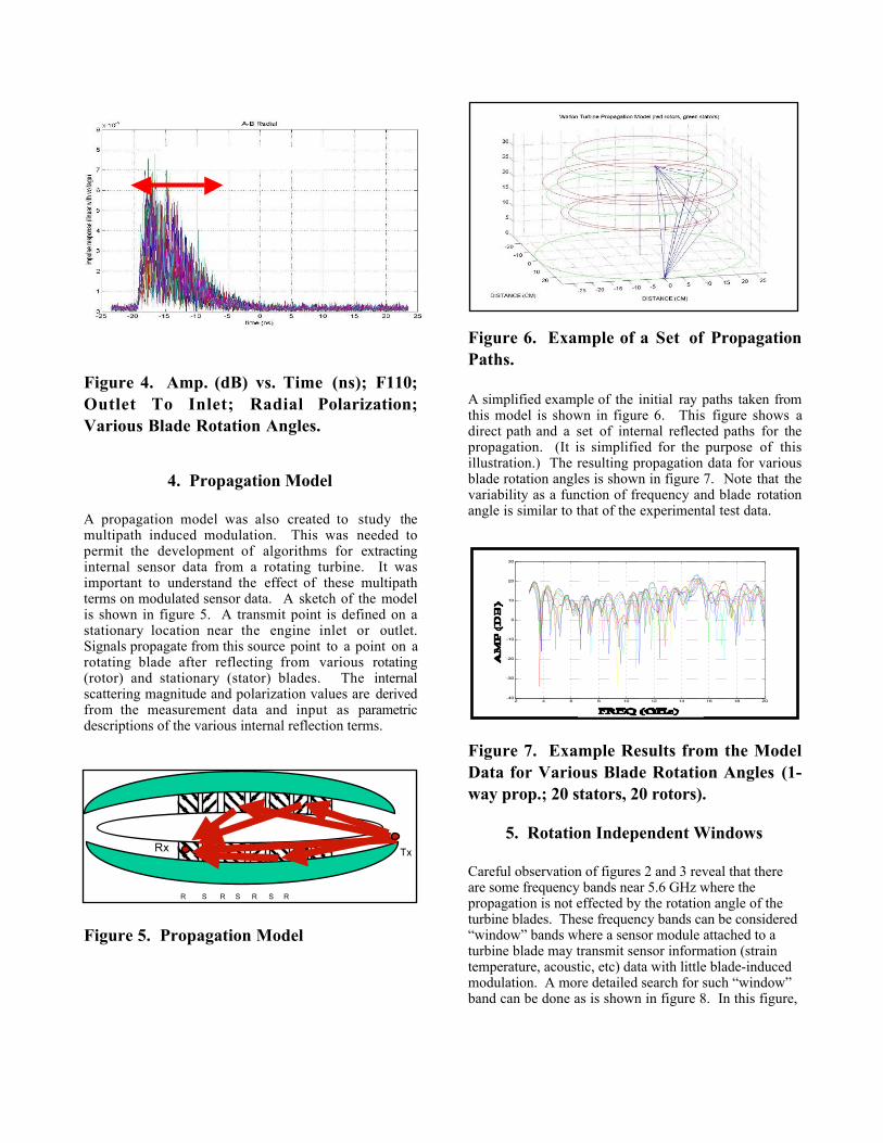
Figure 4. Amp. (dB) vs. Time (ns); F110;Outlet To Inlet; Radial Polarization;Various Blade Rotation Angles.
4. Propagation Model
A propagation model was also created to study themultipath induced modulation. This was needed topermit the development of algorithms for extractinginternal sensor data from a rotating turbine. It wasimportant to understand the effect of these multipathterms on modulated sensor data. A sketch of the modelis shown in figure 5. A transmit point is defined on astationary location near the engine inlet or outlet.Signals propagate from this source point to a point on arotating blade after reflecting from various rotating(rotor) and stationary (stator) blades. The internalscattering magnitude and polarization values are derivedfrom the measurement data and input as parametricdescriptions of the various internal reflection terms.
Figure 5. Propagation Model
Figure 6. Example of a Set of PropagationPaths.
A simplified example of the initial ray paths taken fromthis model is shown in figure 6. This figure shows adirect path and a set of internal reflected paths for thepropagation. (It is simplified for the purpose of thisillustration.) The resulting propagation data for variousblade rotation angles is shown in figure 7. Note that thevariability as a function of frequency and blade rotationangle is similar to that of the experimental test data.
Figure 7. Example Results from the ModelData for Various Blade Rotation Angles (1-way prop.; 20 stators, 20 rotors).
5. Rotation Independent Windows
Careful observation of figures 2 and 3 reveal that thereare some frequency bands near 5.6 GHz where thepropagation is not effected by the rotation angle of theturbine blades. These frequency bands can be considered“window” bands where a sensor module attached to aturbine blade may transmit sensor information (straintemperature, acoustic, etc) data with little blade-inducedmodulation. A more detailed search for such “window”band can be done as is shown in figure 8. In this figure,
RING DOWN TIME
R S R S R S R
TxRx
2 4 6 8 10 12 14 16 18 20-40
-30
-20
-10
0
10
20
30
FREQ bigger f16 Turbine model (with floor bounce)
SIGNAL AMPLITUDE (DB)
ONE-WAY TURBINE PROPAGATION, 20 stators & 20 rotors
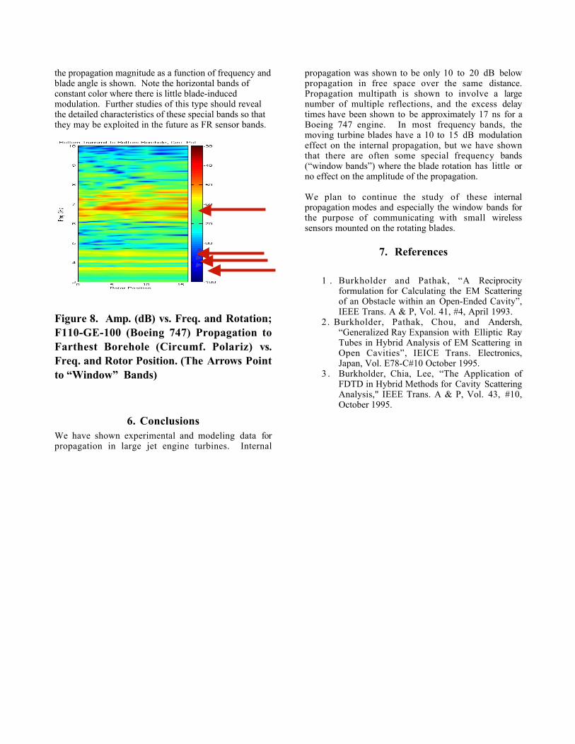
the propagation magnitude as a function of frequency andblade angle is shown. Note the horizontal bands ofconstant color where there is little blade-inducedmodulation. Further studies of this type should revealthe detailed characteristics of these special bands so thatthey may be exploited in the future as FR sensor bands.
Figure 8. Amp. (dB) vs. Freq. and Rotation;F110-GE-100 (Boeing 747) Propagation toFarthest Borehole (Circumf. Polariz) vs.Freq. and Rotor Position. (The Arrows Pointto “Window” Bands)
6. Conclusions We have shown experimental and modeling data forpropagation in large jet engine turbines. Internal
propagation was shown to be only 10 to 20 dB belowpropagation in free space over the same distance. Propagation multipath is shown to involve a largenumber of multiple reflections, and the excess delaytimes have been shown to be approximately 17 ns for aBoeing 747 engine. In most frequency bands, themoving turbine blades have a 10 to 15 dB modulationeffect on the internal propagation, but we have shownthat there are often some special frequency bands(“window bands”) where the blade rotation has little orno effect on the amplitude of the propagation. We plan to continue the study of these internalpropagation modes and especially the window bands forthe purpose of communicating with small wirelesssensors mounted on the rotating blades.
7. References
1 . Burkholder and Pathak, “A Reciprocityformulation for Calculating the EM Scatteringof an Obstacle within an Open-Ended Cavity”,IEEE Trans. A & P, Vol. 41, #4, April 1993.
2. Burkholder, Pathak, Chou, and Andersh,“Generalized Ray Expansion with Elliptic RayTubes in Hybrid Analysis of EM Scattering inOpen Cavities”, IEICE Trans. Electronics,Japan, Vol. E78-C#10 October 1995.
3 . Burkholder, Chia, Lee, “The Application ofFDTD in Hybrid Methods for Cavity ScatteringAnalysis," IEEE Trans. A & P, Vol. 43, #10,October 1995.